Fragmented condensation in Bose-Hubbard trimers with tunable tunnelling
17 (2008) 224–231www.elsevier.com/locate/autcon
Automation in Construction
New generation automated drilling machine for tunnellingand underground mining work☆
Jacek Karliński ⁎, Eugeniusz Rusiński, Tadeusz Lewandowski
Wrocław University of Technology-Institute of Machines Design and Operation, Lukasiewicza 7/9, 50-371 Wroclaw, Poland
Abstract
Selected problems of designing a new generation automated drilling machine for tunnelling and underground mining work are presented. Therequirements needed to build a machine of this class were identified and collected. An original concept of the self-propelled drilling machine wasdeveloped. A virtual model of the machine was created and subjected to different numerical cases of loading. FEM strength calculations of the load-bearing structureswere carried out. All themachine's work operations have been fully automated. The result is a neworiginal automated drillingmachine.© 2007 Elsevier B.V. All rights reserved.
Keywords: FEM; Drilling machine; Mining
1. Introduction
Drilling machines find application in tunnelling and miningexcavation. Such machines must be functional and meet userexpectations. A new original automated modular drillingmachine shown in Fig. 1 is proposed.
Depending on the model, the Self-Propelled MiningMachine can be used to drill shot holes or anchor holes. Allits types and varieties have an identical complete tractor and afront platform (Fig. 1) and differ mainly in the work booms andtheir attachments. The new generation drilling machine'sintended use is roof bolting or (after retooling and hydraulicsystem modification) shot hole boring in tunnelling andunderground mining excavation.
The drilling machine consists of a universal tractor, a frontplatform with an operator protecting structure and a straight-lineboom to which different work tools can be attached. The machinecan fit expansion and adhesive anchors with a length of 1.8–2.6mand a diameter of 28–38 mm and drill shot holes 45–76 mm indiameter and up to 4340 mm long. Thanks to the load-sensinghydraulic system equipped with ergonomic joysticks the work
☆ Paper presented on the 8th International Scientific Conference ComputerAided Engineering, Polanica Zdrój 2006, Poland.⁎ Corresponding author. Tel.: +48 71 3202946; fax: +48 71 3203123.E-mail addresses: [email protected] (J. Karliński),
[email protected] (E. Rusiński),[email protected] (T. Lewandowski).
0926-5805/$ - see front matter © 2007 Elsevier B.V. All rights reserved.doi:10.1016/j.autcon.2007.05.007
tools can be quickly reset and the hydraulic feed can be quicklyadjusted to the power demand of the drifter drills boring shot holesor anchor holes. The modern hydrostatic drive unit allows themachine to negotiate longitudinal elevations at an angle of up to12° in underground excavations and ensures flexible transfer ofdrive from the combustion engine to the road wheels. Meeting allthe noise and exhaust cleanliness the drive unit ensures excellentergonomic conditions for the operator during driving.
Since the operator will work in very difficult environmentalconditions, i.e. at high ambient temperatures (above 35 °C),high humidity (around 95%) and in enclosed areas with limitedair movement (mine faces), the machine should be equippedwith an air-conditioned ergonomic cabin. The machine has anoriginal straight-line boom (Fig. 2) rotatable by 360° whosekinematics enables boring parallel holes in mining excavations35 m2 in cross-section and roof bolting in 7.5 m wide and 7.0 mhigh excavations at one setting of the machine.
Recommendations and guidelines for building the machinewere formulated on the basis of outlet market research.
The first group of recommendations covered the machine'soverall dimensions and parameters:
– transport height: max. 2500 mm;– an optional complete air-conditioned cabin;– the height of excavations for anchoring: max. 6.5 m, thecross-sectional area for drilling: 30÷35 m2;
– the width of excavations for driving: max. 4.5 m;
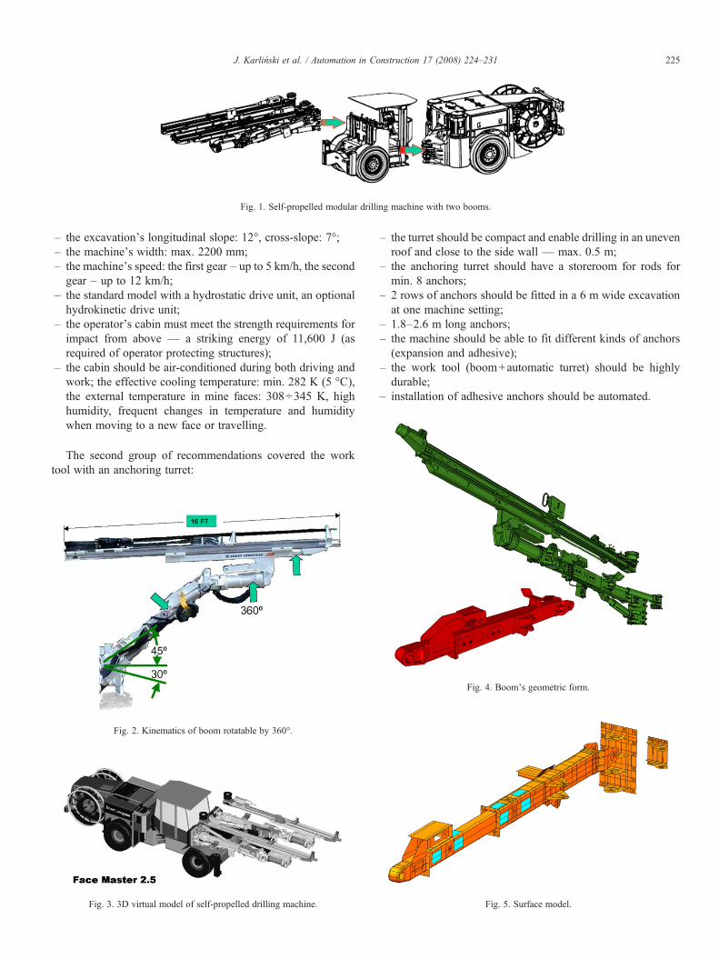
Fig. 1. Self-propelled modular drilling machine with two booms.
225J. Karliński et al. / Automation in Construction 17 (2008) 224–231
– the excavation's longitudinal slope: 12°, cross-slope: 7°;– the machine's width: max. 2200 mm;– the machine's speed: the first gear – up to 5 km/h, the secondgear – up to 12 km/h;
– the standard model with a hydrostatic drive unit, an optionalhydrokinetic drive unit;
– the operator's cabin must meet the strength requirements forimpact from above — a striking energy of 11,600 J (asrequired of operator protecting structures);
– the cabin should be air-conditioned during both driving andwork; the effective cooling temperature: min. 282 K (5 °C),the external temperature in mine faces: 308÷345 K, highhumidity, frequent changes in temperature and humiditywhen moving to a new face or travelling.
The second group of recommendations covered the worktool with an anchoring turret:
Fig. 2. Kinematics of boom rotatable by 360°.
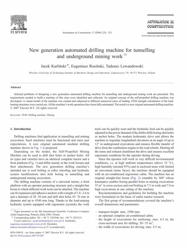
Fig. 3. 3D virtual model of self-propelled drilling machine.
– the turret should be compact and enable drilling in an unevenroof and close to the side wall — max. 0.5 m;
– the anchoring turret should have a storeroom for rods formin. 8 anchors;
– 2 rows of anchors should be fitted in a 6 m wide excavationat one machine setting;
– 1.8–2.6 m long anchors;– the machine should be able to fit different kinds of anchors(expansion and adhesive);
– the work tool (boom+automatic turret) should be highlydurable;
– installation of adhesive anchors should be automated.
Fig. 4. Boom's geometric form.
Fig. 5. Surface model.
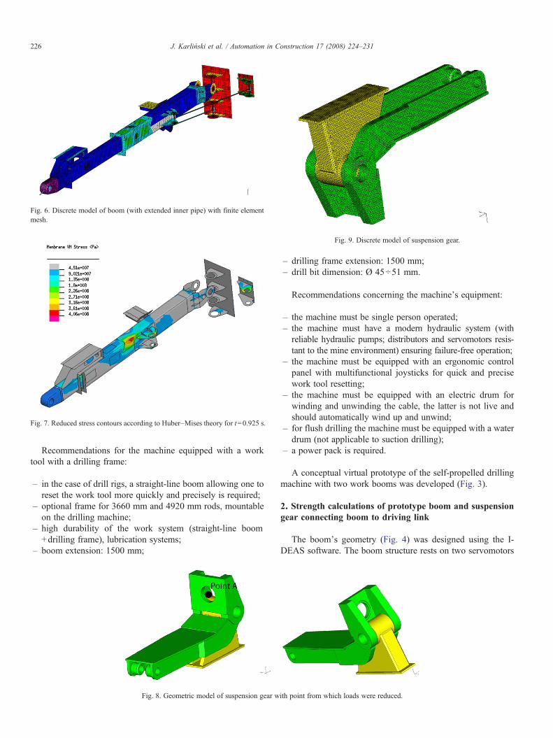
Fig. 6. Discrete model of boom (with extended inner pipe) with finite elementmesh.
Fig. 7. Reduced stress contours according to Huber–Mises theory for t=0.925 s.
Fig. 9. Discrete model of suspension gear.
226 J. Karliński et al. / Automation in Construction 17 (2008) 224–231
Recommendations for the machine equipped with a worktool with a drilling frame:
– in the case of drill rigs, a straight-line boom allowing one toreset the work tool more quickly and precisely is required;
– optional frame for 3660 mm and 4920 mm rods, mountableon the drilling machine;
– high durability of the work system (straight-line boom+drilling frame), lubrication systems;
– boom extension: 1500 mm;
Fig. 8. Geometric model of suspension gear w
– drilling frame extension: 1500 mm;– drill bit dimension: Ø 45÷51 mm.
Recommendations concerning the machine's equipment:
– the machine must be single person operated;– the machine must have a modern hydraulic system (withreliable hydraulic pumps; distributors and servomotors resis-tant to the mine environment) ensuring failure-free operation;
– the machine must be equipped with an ergonomic controlpanel with multifunctional joysticks for quick and precisework tool resetting;
– the machine must be equipped with an electric drum forwinding and unwinding the cable, the latter is not live andshould automatically wind up and unwind;
– for flush drilling the machine must be equipped with a waterdrum (not applicable to suction drilling);
– a power pack is required.
A conceptual virtual prototype of the self-propelled drillingmachine with two work booms was developed (Fig. 3).
2. Strength calculations of prototype boom and suspensiongear connecting boom to driving link
The boom's geometry (Fig. 4) was designed using the I-DEAS software. The boom structure rests on two servomotors
ith point from which loads were reduced.
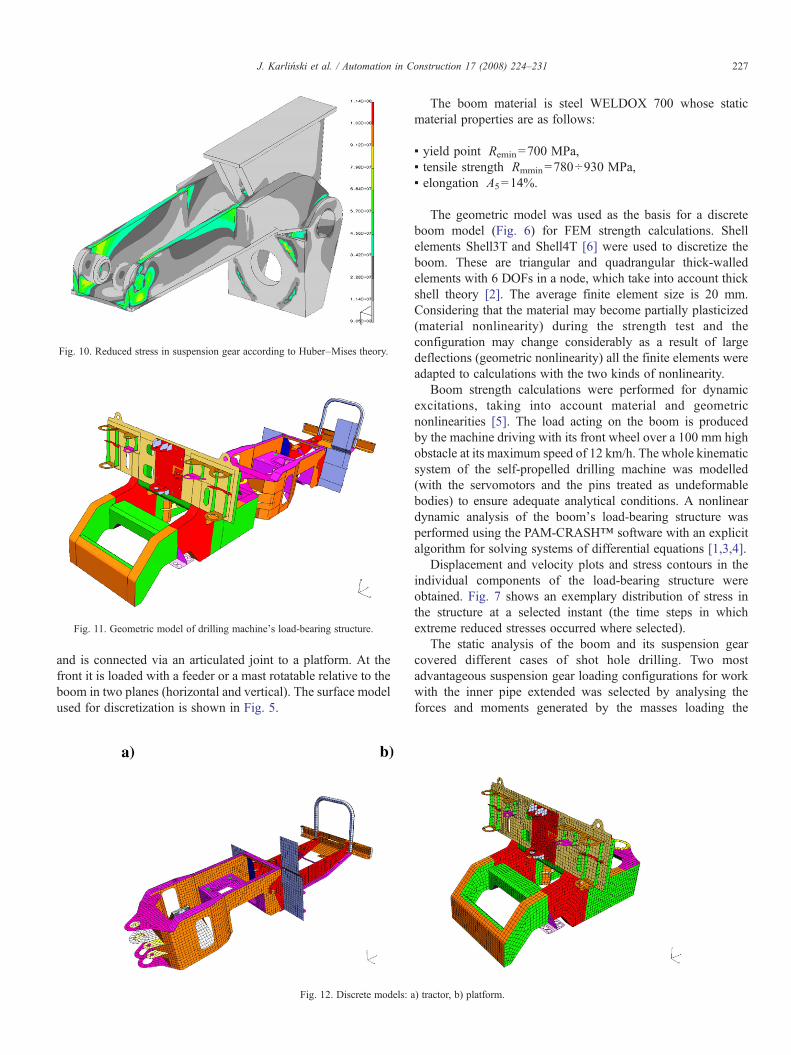
Fig. 10. Reduced stress in suspension gear according to Huber–Mises theory.
Fig. 11. Geometric model of drilling machine's load-bearing structure.
227J. Karliński et al. / Automation in Construction 17 (2008) 224–231
and is connected via an articulated joint to a platform. At thefront it is loaded with a feeder or a mast rotatable relative to theboom in two planes (horizontal and vertical). The surface modelused for discretization is shown in Fig. 5.
Fig. 12. Discrete models: a
The boom material is steel WELDOX 700 whose staticmaterial properties are as follows:
▪ yield point Remin=700 MPa,▪ tensile strength Rmmin=780÷930 MPa,▪ elongation A5=14%.
The geometric model was used as the basis for a discreteboom model (Fig. 6) for FEM strength calculations. Shellelements Shell3T and Shell4T [6] were used to discretize theboom. These are triangular and quadrangular thick-walledelements with 6 DOFs in a node, which take into account thickshell theory [2]. The average finite element size is 20 mm.Considering that the material may become partially plasticized(material nonlinearity) during the strength test and theconfiguration may change considerably as a result of largedeflections (geometric nonlinearity) all the finite elements wereadapted to calculations with the two kinds of nonlinearity.
Boom strength calculations were performed for dynamicexcitations, taking into account material and geometricnonlinearities [5]. The load acting on the boom is producedby the machine driving with its front wheel over a 100 mm highobstacle at its maximum speed of 12 km/h. The whole kinematicsystem of the self-propelled drilling machine was modelled(with the servomotors and the pins treated as undeformablebodies) to ensure adequate analytical conditions. A nonlineardynamic analysis of the boom's load-bearing structure wasperformed using the PAM-CRASH™ software with an explicitalgorithm for solving systems of differential equations [1,3,4].
Displacement and velocity plots and stress contours in theindividual components of the load-bearing structure wereobtained. Fig. 7 shows an exemplary distribution of stress inthe structure at a selected instant (the time steps in whichextreme reduced stresses occurred where selected).
The static analysis of the boom and its suspension gearcovered different cases of shot hole drilling. Two mostadvantageous suspension gear loading configurations for workwith the inner pipe extended was selected by analysing theforces and moments generated by the masses loading the
) tractor, b) platform.
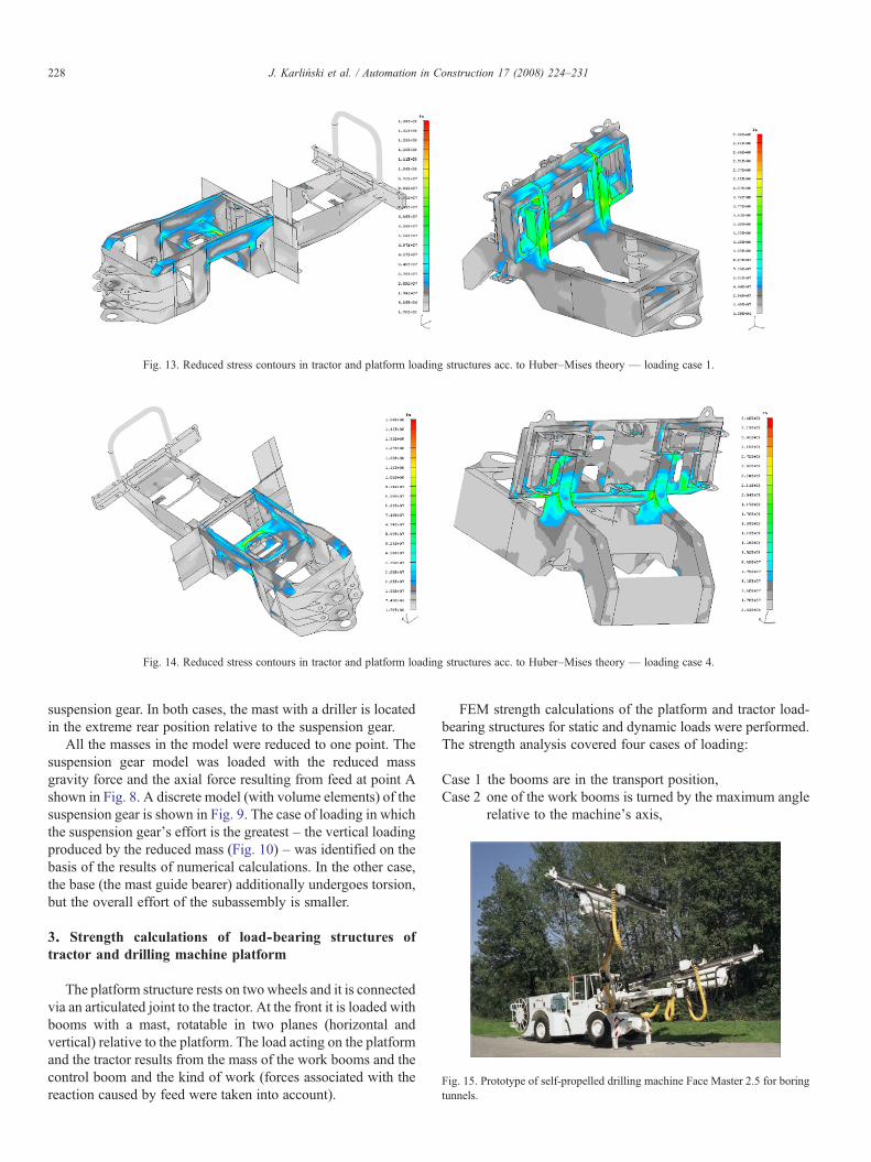
Fig. 13. Reduced stress contours in tractor and platform loading structures acc. to Huber–Mises theory — loading case 1.
Fig. 14. Reduced stress contours in tractor and platform loading structures acc. to Huber–Mises theory — loading case 4.
Fig. 15. Prototype of self-propelled drilling machine Face Master 2.5 for boringtunnels.
228 J. Karliński et al. / Automation in Construction 17 (2008) 224–231
suspension gear. In both cases, the mast with a driller is locatedin the extreme rear position relative to the suspension gear.
All the masses in the model were reduced to one point. Thesuspension gear model was loaded with the reduced massgravity force and the axial force resulting from feed at point Ashown in Fig. 8. A discrete model (with volume elements) of thesuspension gear is shown in Fig. 9. The case of loading in whichthe suspension gear's effort is the greatest – the vertical loadingproduced by the reduced mass (Fig. 10) – was identified on thebasis of the results of numerical calculations. In the other case,the base (the mast guide bearer) additionally undergoes torsion,but the overall effort of the subassembly is smaller.
3. Strength calculations of load-bearing structures oftractor and drilling machine platform
The platform structure rests on two wheels and it is connectedvia an articulated joint to the tractor. At the front it is loaded withbooms with a mast, rotatable in two planes (horizontal andvertical) relative to the platform. The load acting on the platformand the tractor results from the mass of the work booms and thecontrol boom and the kind of work (forces associated with thereaction caused by feed were taken into account).
FEM strength calculations of the platform and tractor load-bearing structures for static and dynamic loads were performed.The strength analysis covered four cases of loading:
Case 1 the booms are in the transport position,Case 2 one of the work booms is turned by the maximum angle
relative to the machine's axis,
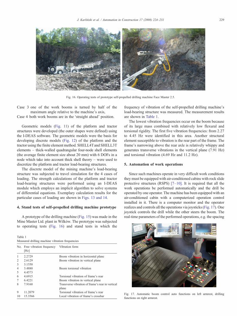
Fig. 16. Operating tests of prototype self-propelled drilling machine Face Master 2.5.
229J. Karliński et al. / Automation in Construction 17 (2008) 224–231
Case 3 one of the work booms is turned by half of themaximum angle relative to the machine's axis,
Case 4 both work booms are in the ‘straight ahead’ position.
Geometric models (Fig. 11) of the platform and tractorstructures were developed (the outer shapes were defined) usingthe I-DEAS software. The geometric models were the basis fordeveloping discrete models (Fig. 12) of the platform and thetractor using the finite element method. SHELL4Tand SHELL3Telements – thick-walled quadrangular four-node shell elements(the average finite element size about 20 mm) with 6 DOFs in anode which take into account thick shell theory – were used todiscretize the platform and tractor load-bearing structures.
The discrete model of the mining machine's load-bearingstructure was subjected to travel simulation for the 4 cases ofloading. The strength calculations of the platform and tractorload-bearing structures were performed using an I-DEASmodule which employs an implicit algorithm to solve systemsof differential equations. Exemplary calculation results for theparticular cases of loading are shown in Figs. 13 and 14.
4. Stand tests of self-propelled drilling machine prototype
A prototype of the drilling machine (Fig. 15) was made in theMine Master Ltd. plant in Wilków. The prototype was subjectedto operating tests (Fig. 16) and stand tests in which the
Table 1Measured drilling machine vibration frequencies
No. Free vibration frequency[Hz]
Vibration form
1 2.2729 Boom vibration in horizontal plane2 2.6129 Boom vibration in vertical plane3 3.15504 3.4880 Boom torsional vibration5 4.45736 4.6915 Torsional vibration of frame's rear7 6.4221 Boom vibration in vertical plane8 7.9160 Transverse vibration of frame's rear in vertical
plane9 11.2079 Torsional vibration of frame's rear10 15.3566 Local vibration of frame's crossbar
frequency of vibration of the self-propelled drilling machine'sload-bearing structure was measured. The measurement resultsare shown in Table 1.
The lowest vibration frequencies occur on the boom becauseof its large mass combined with relatively low flexural andtorsional rigidity. The first five vibration frequencies: from 2.27to 4.45 Hz were identified in this area. Another structuralelement susceptible to vibration is the rear part of the frame. Theframe's narrowing above the rear axle is relatively whippy andgenerates transverse vibrations in the vertical plane (7.91 Hz)and torsional vibration (4.69 Hz and 11.2 Hz).
5. Automation of work operations
Since such machines operate in very difficult work conditionstheymust be equippedwith air-conditioned cabins with rock slideprotective structures (RSPS) [7–10]. It is required that all thework operations be performed automatically and the drill beoperated by one operator. Themachine has been equippedwith anair-conditioned cabin with a computerized operation controlinstalled in it. There is a computer monitor and the operatorrealizes and controls all the operations via joysticks (Fig. 17). Onejoystick controls the drill while the other steers the boom. Thereal-time parameters of the performed operations, e.g. the spacing
Fig. 17. Automatic boom control auto functions on left armrest, drillingfunctions on right armrest.
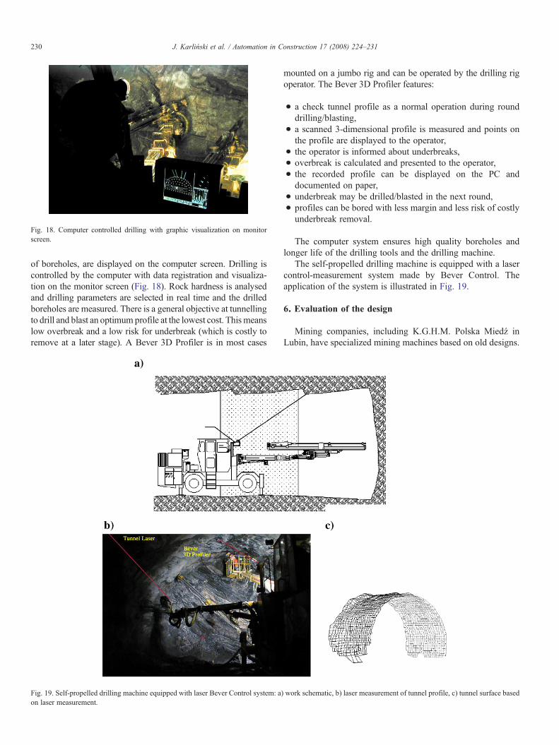
Fig. 18. Computer controlled drilling with graphic visualization on monitorscreen.
230 J. Karliński et al. / Automation in Construction 17 (2008) 224–231
of boreholes, are displayed on the computer screen. Drilling iscontrolled by the computer with data registration and visualiza-tion on the monitor screen (Fig. 18). Rock hardness is analysedand drilling parameters are selected in real time and the drilledboreholes are measured. There is a general objective at tunnellingto drill and blast an optimum profile at the lowest cost. This meanslow overbreak and a low risk for underbreak (which is costly toremove at a later stage). A Bever 3D Profiler is in most cases
Fig. 19. Self-propelled drilling machine equipped with laser Bever Control system: a)on laser measurement.
mounted on a jumbo rig and can be operated by the drilling rigoperator. The Bever 3D Profiler features:
• a check tunnel profile as a normal operation during rounddrilling/blasting,
• a scanned 3-dimensional profile is measured and points onthe profile are displayed to the operator,
• the operator is informed about underbreaks,• overbreak is calculated and presented to the operator,• the recorded profile can be displayed on the PC anddocumented on paper,
• underbreak may be drilled/blasted in the next round,• profiles can be bored with less margin and less risk of costlyunderbreak removal.
The computer system ensures high quality boreholes andlonger life of the drilling tools and the drilling machine.
The self-propelled drilling machine is equipped with a lasercontrol-measurement system made by Bever Control. Theapplication of the system is illustrated in Fig. 19.
6. Evaluation of the design
Mining companies, including K.G.H.M. Polska Miedź inLubin, have specialized mining machines based on old designs.
work schematic, b) laser measurement of tunnel profile, c) tunnel surface based
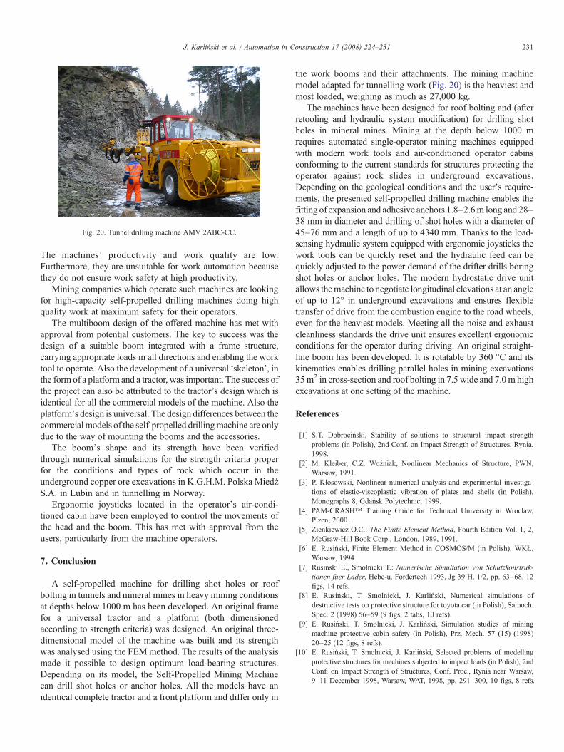
Fig. 20. Tunnel drilling machine AMV 2ABC-CC.
231J. Karliński et al. / Automation in Construction 17 (2008) 224–231
The machines' productivity and work quality are low.Furthermore, they are unsuitable for work automation becausethey do not ensure work safety at high productivity.
Mining companies which operate such machines are lookingfor high-capacity self-propelled drilling machines doing highquality work at maximum safety for their operators.
The multiboom design of the offered machine has met withapproval from potential customers. The key to success was thedesign of a suitable boom integrated with a frame structure,carrying appropriate loads in all directions and enabling the worktool to operate. Also the development of a universal ‘skeleton’, inthe form of a platform and a tractor, was important. The success ofthe project can also be attributed to the tractor's design which isidentical for all the commercial models of the machine. Also theplatform's design is universal. The design differences between thecommercialmodels of the self-propelled drillingmachine are onlydue to the way of mounting the booms and the accessories.
The boom's shape and its strength have been verifiedthrough numerical simulations for the strength criteria properfor the conditions and types of rock which occur in theunderground copper ore excavations in K.G.H.M. Polska MiedźS.A. in Lubin and in tunnelling in Norway.
Ergonomic joysticks located in the operator's air-condi-tioned cabin have been employed to control the movements ofthe head and the boom. This has met with approval from theusers, particularly from the machine operators.
7. Conclusion
A self-propelled machine for drilling shot holes or roofbolting in tunnels and mineral mines in heavy mining conditionsat depths below 1000 m has been developed. An original framefor a universal tractor and a platform (both dimensionedaccording to strength criteria) was designed. An original three-dimensional model of the machine was built and its strengthwas analysed using the FEMmethod. The results of the analysismade it possible to design optimum load-bearing structures.Depending on its model, the Self-Propelled Mining Machinecan drill shot holes or anchor holes. All the models have anidentical complete tractor and a front platform and differ only in
the work booms and their attachments. The mining machinemodel adapted for tunnelling work (Fig. 20) is the heaviest andmost loaded, weighing as much as 27,000 kg.
The machines have been designed for roof bolting and (afterretooling and hydraulic system modification) for drilling shotholes in mineral mines. Mining at the depth below 1000 mrequires automated single-operator mining machines equippedwith modern work tools and air-conditioned operator cabinsconforming to the current standards for structures protecting theoperator against rock slides in underground excavations.Depending on the geological conditions and the user's require-ments, the presented self-propelled drilling machine enables thefitting of expansion and adhesive anchors 1.8–2.6m long and 28–38 mm in diameter and drilling of shot holes with a diameter of45–76 mm and a length of up to 4340 mm. Thanks to the load-sensing hydraulic system equipped with ergonomic joysticks thework tools can be quickly reset and the hydraulic feed can bequickly adjusted to the power demand of the drifter drills boringshot holes or anchor holes. The modern hydrostatic drive unitallows themachine to negotiate longitudinal elevations at an angleof up to 12° in underground excavations and ensures flexibletransfer of drive from the combustion engine to the road wheels,even for the heaviest models. Meeting all the noise and exhaustcleanliness standards the drive unit ensures excellent ergonomicconditions for the operator during driving. An original straight-line boom has been developed. It is rotatable by 360 °C and itskinematics enables drilling parallel holes in mining excavations35m2 in cross-section and roof bolting in 7.5 wide and 7.0m highexcavations at one setting of the machine.
References
[1] S.T. Dobrociński, Stability of solutions to structural impact strengthproblems (in Polish), 2nd Conf. on Impact Strength of Structures, Rynia,1998.
[2] M. Kleiber, C.Z. Woźniak, Nonlinear Mechanics of Structure, PWN,Warsaw, 1991.
[3] P. Kłosowski, Nonlinear numerical analysis and experimental investiga-tions of elastic-viscoplastic vibration of plates and shells (in Polish),Monographs 8, Gdańsk Polytechnic, 1999.
[4] PAM-CRASH™ Training Guide for Technical University in Wroclaw,Plzen, 2000.
[5] Zienkiewicz O.C.: The Finite Element Method, Fourth Edition Vol. 1, 2,McGraw-Hill Book Corp., London, 1989, 1991.
[6] E. Rusiński, Finite Element Method in COSMOS/M (in Polish), WKŁ,Warsaw, 1994.
[7] Rusiński E., Smolnicki T.: Numerische Simultation von Schutzkonstruk-tionen fuer Lader, Hebe-u. Fordertech 1993, Jg 39 H. 1/2, pp. 63–68, 12figs, 14 refs.
[8] E. Rusiński, T. Smolnicki, J. Karliński, Numerical simulations ofdestructive tests on protective structure for toyota car (in Polish), Samoch.Spec. 2 (1998) 56–59 (9 figs, 2 tabs, 10 refs).
[9] E. Rusiński, T. Smolnicki, J. Karliński, Simulation studies of miningmachine protective cabin safety (in Polish), Prz. Mech. 57 (15) (1998)20–25 (12 figs, 8 refs).
[10] E. Rusiński, T. Smolnicki, J. Karliński, Selected problems of modellingprotective structures for machines subjected to impact loads (in Polish), 2ndConf. on Impact Strength of Structures, Conf. Proc., Rynia near Warsaw,9–11 December 1998, Warsaw, WAT, 1998, pp. 291–300, 10 figs, 8 refs.
Copyright © 2022 FDOKUMEN