CS2060 -HIGH SPEED NETWORKS PART-A UNIT I -HIGH SPEED NETWORKS
Upload
khangminh22Category
view
5download
0
NOVEMBER 1976 NETWORKS (File as Card A on Networks)
MANUFACTURED DISCONTINUED
The manufacturer of the following networks has been discontinued and it is not con- sidered necessary to maintain complete information in the catalogue.
For information on codes not listed below see other cards on networks.
northam tclccum
CODE REPLACED BY CODE REPLACED BY
MD9050 NE-425B NE-425BQlA NE-425C NE-425D NE-425E NE-425QlA NE-425QB NE-425QC NE-453QlA type NE-454QlA type
NE-425QlA NE-425E NE-425QC
(a)NE-425QDl (a)NE-425QEl (a)NE-425QFl (a)NE-425QF2 (a)NE-425E2
QNBZAl QNBZAZ QNB3A QNB3Al QNB3Al QNB3A2 QNB6A QNBllC QNB22A QNB34B
(a) Leads for terminating'at the network must be equipped with Pl7A227, P16E525 or P99P816 cord tips for 27 gauge stranded, tinsel or 22 gauge stranded cable, respectively.
P~O~~~~y OF Northern Telecom Limited

JANUARY 1965 NETWORKS MANUFACTURE
(File as Card 1 on Networks) DISCONTINUED
The manufacture of the following networks has been discontinued and it is not considered necessary to maintain complete information in the catalogue.
For information on codes not listed below, see other cards on networks.
Code Replaced by
11A to D 11E 102A (a) 11F to J 12AtoM 13A to N 13P (b) ;c> 13R 13s (d) ;e> 13T (0 (9) 13u 13u 16A 178 to G 17H (3
(a) Balancing network.
Code
175 18A 19A 20A 21A 22A 23A 24A 25A 25B 25C 26A 26B 27A
Replaced by
(4
(i)
102A(a) 102D(a) 102B(a) 102E(a) 102F(a) 103A(a)
Code Replaced b] Code
28A 29A 30A 31A 32A 33A 34A 35A 36A 37A & B 38A 39A 39B 39c
102E(a) 103A(a)
104B(a) 104A(a)
104A(a) 104B(a) 104C(a)
Replaced by
39D 104D(a) 115F 115BL 15OA & B - 151A 157A 158A 159B 160E 167A 176A 178A recom. 177L 181A 177A 181C 177c 181D 177D
Code
181E 181F 1816 181H 1815 181K 181L 182A 183A 183B 184A 185B 186C
Replaced by
177E 177F 177G 177K 1775 177K 177L 178A 179A 179B 185A
185A recom.
(b) Replaced by 115AR plus a 38A bracket and a D-77985 mounting plate. (c) 13P and 17H when used together, replaced by 115AR plus a 38A bracket and a D77985 mounting plate. (d) Replaced by 115AJ plus a 38A bracket and a D77985 mounting plate. (e) 13s and 175 when used together, replaced by 115A.J plus a 38A bracket and a D77985 mounting plate. (f) Replaced by 115AP plus a 38A bracket and a D77985 mounting plate. (g) 13T and 22A when used together, replaced by 115AP plus a 38A bracket and a D77985 mounting plate.

JANUARY 1965 I
Code i
Replaced by
210A 210B 21oc 210D 210E 210F 21OG 21OH 221A 226C 226D 2263 4258 439A 473A 474c h D 700A 7ol.A 702A 703A 703B 704A&B aooc 800D 800E 8OOF
210K
21OL 21w 210N 21OP 210R 210s
226.4
703B (b)
BOOBC 800BD 800BE 800BF
(a) Replaced by 226W filter.
Code Replaced by -_--
8OOG 800H 8003 800K 800T 800M 800AE 800-X 800.4P 8QOAR 8008s 8OOAT 8OOAW 801A 801B 801C BOLD 8OlE 801F 801G 801H 801Y 802G 803C 803F 80s
800BG 800BH 800B.J SOOBK 800BA BOOAU 800AB 8OOAF
8OlAA 8OlAB 801AC 8OlAD BOYLE 80lA.F BOLAG 8OlA.H BOOAF 8OOAG 803u 803AB 808C
NETWORKS HANWAcruxE DE.CONTlNU&D
(File as Card 2 on Networks)
Code
81OA 81s 813A 8i4A 825.4 825B 825C 825D 8253 825F 825G 825H 8255 825K 825T 825U 825W 825Y 825AA 825AB 825AC 825AD 825AE 825AF 825AG 825AE
Replaced by
81OC (4 813C
- 825JB 825JK 82532
825KU 825BS 825KE 825W 825KG 825KL 825.J-M 825EiH 825LA 825LB 825LC 825LD 825LE 825LF 825LG 825LE 825L.J 825LK
Code Replaced by Code Replaced by I
825AJ 825LL 825AK 825IX 825AL 825LN 825AM 825LP 825AN 825LR 825AP 825JG 825AR 82555 825AS 825JA 825AT. 825EU 825AU 825HN 825AY 825HW 825BE 825JN 825BF 825ET 825BG 825HJ 825EK 825IfR 825BM 825KN 825CL 825DA * 825JP 825DH 825KW 825DL 825KR 825DN 825Ks 825DN 825KT 825DT 825LY 825DU 825LU 825EB
825EH 825gI 825W 825BS 82533'1: 825ELI 825EW 825KY 825FA 825FB 825FD 825FE 825FG 825FH 825F.J 825FK 825FL 825pM 825FN 825FP 825FR 825FS 825FU 825FW 825FY
825KY 825LU 825KP 825KIZ 825JC
m 825KB 825KC 825KD 825JR 825KX 825W 825Bo 825KM
- c
82555
- 825JD 825JE 825LS 825LT
825EC l825GB 825JW
(b) NSl4541 network recommended. (c) 812C or D recommended.
a . .

JUNE 1966 NETWORKS (File as Card 3 on NetWorks)
MANUFACTURE
DISCONTINUED
Code Replaced by
825GC 825GD 825GE 825GF 825GG 825G.J 825GK 825GL 825GM 825GN- 825GP
825MB 825HM 825HY 825RA 82553 825K.J
825HL
825HP
Code Replaced by
825GR 825GS 825GT 825GW 825GY 825HB 825HC 825HD 826A 826B
825MC 825JF 825BK 825JT 825JU 825JY 826AA 826AB
Code
826C 826D 8263 826F 8266 826L 826M 8263 826R 826T
Replaced by
826AC 826AD 826AF 826Y 826A.l 826AH 826AG 826AE 826V 826AK
Code Replaced by
826U 826~~ 900A 901A 902A 903A 904A 905A 4010A 4010B 4019N 4019AB 4082D to F

SEPTEMBER 1970 NE-115 TYPE NETWORKS (Card 1)
SEE RATINGS BELOW
FIG I FIG 2 FIG 3
-7
Consists of miscellaneous apparatus enclosed in a metal container provided with a removable cover.
Intended for use with two wire repeaters to balance the impedance of the telephone circujts or apparatus as listed below.
Closest recommended mounting centres are 1.750 inches by 7.000 inches.
Code
Terminal Arrangement
Fig
NE-115A 1 NE-115B 1 NE-115C 1
NE-115D (b)2
Gauge
(a)19 (a) 19 (a)22
Used With
Circuit
CNB-H-135 Cable DNB-H-135 Cable BSA-H-135 Cable
Rating
Standard 11 II
TH, CNB, DNB, 11
BSA and ASM non-loaded Cable 3
(a)19 DNB-H-175 Cable ,I I NE-115E 1 5 125
NE-115G 2 CNB-M-88 BSA-M-88 Cab1es
II
'5 NE-115H 2 CNB-H-88
BSA-H-88 Cab1es .) "
1 (a) Copper conductors. (b) Terminals 2 and 4 are electrically common.

SEPTEMBER 1970
Terminal
NE-115 TYPE NETWORKS (Card 2)
Used With
SEE RATINGS BELOW
Code Arrangement
Fig Gauge Circuit Rating NE-115J NE-115K NE-115L NE-115M NE-115P NE-115R NE-115s NE-115T NE-115U NE-115W NE-115Y
NE-115AA
NE-115AB NE-115AC NE-115AD NE-115AE NE-115AF NE-115AG NE-115AH
1 1 1 1 2 2
Cd (b)3 (b)3 (b)2
(b)3
1 1 1
04: (b)3
2
(4 19 (a) 19 (a> 19 (4 19 (a> 19 (a) 19 (a) 22 (a)104 mils (a)128 mils (a)165 mils (a)104 mils
i (a)128 mils (a)165 mils (a) 19 (a) 16 (a) 19 (a) 16 (a) 19 (a) 19 (a) 19
CNB-B-135 Cable DNB-B-135 Cable CNB-B-88 Cable DNB-B-88 Cable H-88-S Toll Cable H-50-P Toll Cable BSA-B-135 Cable Open Wire-Side-6, 8 or 12 inch spacing Open Wire-Side-6, 8 or 12 inch spacing Open Wire-Side-6, 8 or 12 inch spacing Open Wire-Phantom-12 inch spacing
Open Wire-Phantom-12 inch spacing
H-31-S Toll Entrance Cable H-31-S Toll Entrance Cable H-18-P Toll Entrance Cable H-18-P Toll Entrance Cable B-88-S Toll Cable B-50-P Toll Cable H-44-S Toll Cable
(a) Copper conductors. (b) Terminals 2, 3 and 4 are electrically common.

SEPTEMBER 1970 NE-115 TYPE NETWORKS SEE RATINGS BELOW
(Card 3)
Terminal Used With Arrangement
Code Fig Gauge Circuit Rating
NE-115A.J 2 (a) 19 H-25-P Toll Cable Standard NE-115AK 3 (a) 24 DSM & CSM Non-Loaded Cables 11
NE-115AL 4 (a) 24 CSM-H-88 and DSM-H-88 Cables II
NE-115AM 5 H-172-S Toll Cable H-172-S Toll Cable 1
NE-115AN 5 H-63-P Toll Cable H-63-P Toll Cable I
NE-115AR (b)3 Open Wire-Side-6, 8 NE-115AS (c)3 NE-115AT (b)2 NE-115AW (b)2 NE-115AY (b)2 NE-115BA (b)3 NE-115BB (b)3 NE-115BD (c)3
(a) 80 mils (d)134 mils (d)109 mils (d)109 mils (e)104 mils (e)128 mils (e)104 mils
or 12 inch spacing or 12 inch spacing Open Wire-Phantom-8
Open Wire-Side-12 inch spacing Open Wire-Side-12 inch spacing Open Wire-Phantom-12 inch spacing Open Wire-Side-6, 8 or 12 inch spacing Open Wire-Side-6, 8 or 12 inch spacing Open Wire-Phantom-8 or 12 inch spacing
I, II
NE-115BG 4 (a) 16 H-32-P Toll Cable (a) 19 H-32-P Toll Cable
NE-115BL 3 Subscriber Sets NE-115BM 3 (a) 16 H-44-S Toll Cable NE-115BN 3 (a) 16 H-25-P Toll Cable
I 8,
II II II
(a) Copper conductors. (b) Terminals 2, 3 and 4 are electrically common. (c) Terminals 2, 3 and 4 are electrically common. There are no electrical connections to terminal 6. (d) Steel conductors. (e) Copper-clad steel conductors.

SEPTEMBER 1970 NE-115 TYPE NETWORKS (Card 4)
SEE RATINGS BELOW
Code
NE-115BT
NE-115BU
NE-115BW
NE-115BY
NE-115CA
NE-115CB
NE-115CC
NE-115CD
Terminal Arrangement
Fig
3
2
2
3
2
2
2
2
Gauge
(a)13 (a) 16 (4 19
I
(413 (a)16 (a)19
I
(a)13 (a)16 (a) 19.
I
(a)13 (a) 16 (4 19 (a) 13
I (a) 16 (a) 19 (4 13
I (a) 16 (4 19
I
(a)13 (416 (a)19 (a) 13 (a) 16 (a> 19
Used With
Circuit
H-31-18 Toll Entrance Cable H-31-18 Toll Entrance Cable H-31-18 Toll Entrance Cable 1 H-31-18 Toll Entrance Cable H-31-18 Toll Entrance Cable H-31-18 Toll Entrance Cable H-31-18 Toll Entrance Cable
1
H-31-18 Toll Entrance Cable H-31-18 Toll Entrance Cable 1 H-28-16 Toll Entrance Cable H-28-16 Toll Entrance Cable H-28-16 Toll Entrance Cable 1 H-31-18 Toll Entrance Cable H-31-18 Toll Entrance Cable H-31-18 Toll Entrance Cable 1 H-31-18 Toll Entrance Cable H-31-18 Toll Entrance Cable H-31-18 Toll Entrance Cable 1 H-28-16 Toll Entrance Cable H-28-16 Toll Entrance Cable H-28-16 Toll Entrance Cable 1 H-28-16 Toll Entrance Cable H-28-16 Toll Entrance Cable H-28-16 Toll Entrance Cable 1
Rating
Standard
I,
1,
(a) Copper conductors.

SEPTEMBER 1970 NE-115 TYPE NETWORKS (Card 5)
SEE RATINGS BELOW
Code
Terminal Arrangement
Fig Gauge
Used With
Circuit Rating
NE-115CE 4 (4 26 AST-H-88 Exchange Cable (4 26 BST-H-88 Exchange Cable 1
Standard
(a) Copper conductors.

DECEMBER 1971 NE-153C NETWORK STANDARD
Resistors enclosed in a metal case.
Closest recommended mounting centres are 1.188 inches by 1.50 inches.
J
NE-153C
NE-153A ALSO GENERAL DESIGN AND DIMENSIONS Of NE-l53C
Intended for use as an output bridge in the auxiliary receiving amplifier of the type K carrier telephone system.

DECEMBER 1971 NE-155A NETWORK STANDARD
Capacitors and inductors enclosed in a sheet metal case.
Closest recommended mounting centres are 3.50 inches by 4.50 inches.
Intended for use in the NE-86A filter as a voice repeater balancing network for the NE-85C filter used in the NE-H1 carrier telephone system.

DECEMBER 1971 NE-156A NETWORK STANDARD
Inductors and resistors enclosed in an aluminum case.
Closest recommended mounting centres are 1.00 inches by 1.750 inches.
Intended for use as a phantom balancing network to balance one NE-85C filter or one NE-208F filter in the NE-H1 carrier telephone system.

DECEMBER 1971 NE-162B NETWORK STANDARD
Inductors, capacitors, and resistors enclosed in a metal case.
Closest recommended mounting centres are 3.312 inches by 2.562 inches.
Intended for use in the transmitting amplifiers of the type NE-J carrier telephone system.

FEBRUARY 1972 NE-166A NETWORK STANDARD
Consists of an inductor, resistor, and capacitor potted in a metal case.
Closest recommended mounting centres are 1.750 inches by 3.50 inches.
Intended to operate in a 605 ohm circuit.
Intended for use in the C5 carrier telephone terminal and the 2B carrier pilot channel for building out line sections to a standard length in the type C carrier telephone systems.
Frequency Range Loss
(hertz) (db) at Freq (hertz)
4,900 to 15,700 4 15,000

.JANUARY 1965 Nos. 168A & B NETWORKS SEE RATINGS BELOW
! NOS. 168 A KB
Retardation coils, condensers and resistances enclosed in a metal case.
Each network designed to operate in a 605 ohm circuit. Closest recommended mounting centers are 2-5/8 inches by 3-l/2
inches. Intended for use in the 2B carrier pilot channel in the type “C”
carrier telephone systems, to compensate for variation of line losses due principally to changes in weather conditions.
Code No.
168A 168B
Frequency Losses _~.--. ~~ ..~ ~~~ ~~~. Range (Cycles) (db) at Frcq. (Cycles) Rating
5,000 to 15,400 20 15,000 Standard 16,000 to 28,100 20 28,000 ‘I

FEBRUARY 1972 NE-168 B NETWORK STANDARD
Inductors, capacitors, and resistors enclosed in a metal case.
Designed to operate in a 605 ohm circuit.
Closest recommended mounting centres are 2.625 inches by 3.500 inches.
Intended for use in the 2B carrier pilot channel in the C type carrier telephone systems, to compensate for variation of line losses due principally to changes in weather conditions.
Frequency Range (Hertz)
16,000 to 28,100
Losses
(db) at Freq (Hertz)
20 28,000

DECEMBER 1971 NE-170A NETWORK STANDARD
Capacitors, inductors and a resistor enclosed in a metal case.
A balanced structure for use between 600 ohm impedances.
Closest recommended mounting centres are 2.688 inches by 4.438 inches.
Intended for use at auxiliary repeaters of the type NE-J carrier telephone system to connect together the office sides of the two low-pass line filters.

OCTOBER 1969 NE-I7IA NETWORK STANDARD
Five constant resistance equalizer sections enclosed in a metal case.
Operates over a frequency range of 36000 to 84000 hertz.
Closest recommended mounting centres are 4.375 inches by 6.125 inches.
OCTOBER 1969 NE- 172 TYPE NETWORKS SEE RATINGS BELOW
1 43: I
0 0
NE-172A 8 6.
I
I
NE-l72C
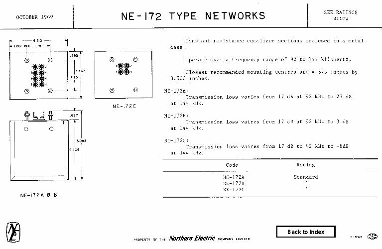
Constant resistance equalizer sections enclosed in a metal case.
Operate over a frequency range of 92 to 144 kilohertz.
Closest recommended mounting centres are 4.375 inches by 3.500 inches.
NE-172A: Transmission loss varies from 17 dB at 92 kHz to 23 dB
at 144 kHz.
NE-172B: Transmission loss vaires from 17 dB at 92 kHz to 3 dB
at 144 kHz.
NE-172C: Transmission loss vaires from 17 dB to 92 kHz to -8dB
at 144 kHz.
Code
NE-172A NE-172B NE-172C
Rating
Standard 11 3,

DECEMBER 1971 NE-177 TYPE NETWORKS SEE RATINGS BELOW
FIG 2
FIG B
WE-,-,,A. ALSO GENERAL DESIGN AND
DIMENSIONS OF ME-177 TYPE.
Consists of one or two capacitors and one or two resistors potted in a metal case.
Intended to reduce sparking at contacts in dial telephone systems.
Terminal letters are stamped on the opposite end of case from terminals.
Closest recommended mounting centres are .50 inch by 1.50 inches.
Capacitors are tested at 500 volts dc between terminals. Suitable for use on continuously applied potentials not exceeding 200 volts dc or inpulse voltages not exceeding 300 volts peak, at a rate not exceeding 50 pulses per second, at operating temperatures not exceeding 49'C.
Consists of Schematic Code Fig Capacitor Resistor Figure Rating
NE-177A 1 1.0 PF 150 Ohms A Standard NE-177B 1 0.1 uF 150 Ohms A ,,
NE-177C 2 0.50 nF 470 Ohms 0.50 PF 470 Ohms I
B NE-177D 1 1.0 I.IF 560 Ohms A 11 NE-177E 1 0.50 nF 150 Ohms A II NE-177F 1 0.50 nF 1000 Ohms A 11 NE-177G 1 0.25 uF 560 Ohms A 11
NE-177H 2 0.50 I.IF 150 Ohms 11 0.50 ~.IF 150 Ohms
1 B
NE-177.J 1 1.0 nF 100 Ohms A 11
NE-177K 2 0.50 ~.IF 100 Ohms 0.50 nF 100 Ohms

DECEMBER 1971 NE-l78A &NE-179 TYPE NETWORKS SEE RATINGS BELOW
NE-179 A% 8
zlLA!v- FIG I
Consists of a capacitor or capacitors and a resistor potted in a metal case.
Intended for use to reduce sparking at the contacts of switches in step-by-step dial telephone systems.
Suitable for use on continuously applied potentials not exceeding 200 volts dc or an impulse voltage not exceeding 300 volts peak, at a rate not exceeding 50 pulses per second at operating temperatures not exceeding 490C.
Capacitors are tested at 500 volts dc between terminals.
Terminal designations are stamped on the end of the case.
Consists of
Code Resistor Cauacitor Schematic Ratine
FIG 2
'NE-178A NE-179A NE-179B
150 ohms Fig 1 Standard 150 Ohms 1 UF Fig 2 II 150 ohms 0.1 uF Fig 2 ,I
NE-17.3A. ALSO GENERAL OESIGN AN0 DIMENSIONS OF NE-179 TYPE

FEBRUARY 1973 NE-180A NETWORK STANDARD
Consists of a 0.30 uF (minimum) capacitor connected in series with a 150 ohm resistor and encased in a block of insulating material.
Suitable for use on impulse voltages not exceeding 350 volts peak at a rate not exceeding 50 pulses per second at operating temperatures not exceeding 660C.
Tested on 800 volts dc between terminals.
Arranged to mount by means of one of the mounting screws furnished with the relays and a nut and washer are provided for this purpose.
Intended for contact protection of relays in NE-5 crossbar systems.

AUGUST 1976 1 NE-185 TYPE 81 NE-186 TYPE NETWORKS 1 SEE RATINGS BELOW
I
Consists of a tubular capacitor connected in series with a resistor contained inside the capacitor. Provided with two tinned wire terminal leads.
Intended for contact protection of relays in telephone
Suitable for use on impulse voltages not exceeding 350 volts peak at a rate not exceeding 50 pulses per second and at operating temperatures not exceeding 660C.
Tested on 800 volts dc between terminals.
NE-185C & NE-186D:
Suitable for use on impulse voltages not exceeding 250 volts peak at a rate not exceeding 50 pulses per second and at operating temperatures not exceeding 66OC.
Tested at 600 volts dc between terminals.
Code
Dimensions (Inches)
"A" "B" Resistance
(Ohms)
Capacitance (uF) at 60 Hertz
Min Max Rating
NE-185A 1.375 0.453 470 11 .15 Standard NE-185C 1.375 0.485 560 :20 .30 II NE-186A 1.875 0.547 120 .30 .40 I, NE-186B 1.875 0.703 1000 .625 II NE-186D 1.875 0.535 270 ,, NE-1860A 1.875 0.750 700 :59705 ,t
rbt northern tclcrcunl
PR~~~~~~ OF Northern Telecom Limited

NOVEMBER 1971 NE-187 TYPE NETWORKS SEE RATINGS BELOW
Each consists of apparatus such as capacitors, resistors and inductors assembled in a metal case.
Intended for use as interstage networks in amplifiers of the L type carrier telephone system.
Closest recommended mounting centres are 2.625 inches by 1.750 inches.
Used in amplifier which supplies a carrier
Code frequency of (kHz) Rating
NE-187A 620 Standard NE-187B 1116 11 NE-187C 1364 11 NE-187D 1612 I, NE-187E 1860 ,, NE-187F 2108 ,I NE-187G 2356 0,
NE-187H NE-187J ;ba; 1, 11
NE-187K 3100 II
(a) Used in an IF amplifier. Network has a frequency range of 312 kHz to 552 kHz.
(b) 420, 468, 516, 564 and 612 kHz.

NOVEMBER 1971 NE-188A NETWORK STANDARD
Consists of an inductor, resistors and capacitors enclosed in a metal case.
Operates over the frequency range of 60 kHz to 108 kHz.
Intended for use as the interstage network of the auxiliary amplifier for the K2 type auxiliary receiving amplifier and L carrier telephone terminals.
Closest recommended mounting centres are 1.750 inches by 2.625 inches.
f

FEBRUARY 1972 NE-189A NETWORK STANDARD
Consists of a resistor, and capacitor combination connected in parallel and bridged across the two terminals of a coaxial jack, thus providing specific values of capacitance and resistance. The sleeve of the jack is grounded to the case in which these components are contained.
Forms part of the 6077A test set.
Intended for use as a primary standard in making periodic adjustments of the in and out capacitances in the 77A test set.

JANUARY 1965 Nos. p!Ad 8c B NETWORKS I
II 11-i
I-
,a “crwc”a”
--+---- -J
SEE RATINGS BELOW
Each network consists essentially of a resistance and con- denser combination connected in parallel and bridged across the two terminals of a coaxial jack, thus provid- ing specific values of capacitance and resistance. The sleeve of the jack is grounded to the can in which these components are contained.
These networks are the same except for the capacitance values.
They are intended for use as primary standards in mak- ing periodic adjustments of the in and out capacitances in the No. VA test set.
Form part of the No, 60’77A test set.
Code No. Rating
189B STANDARD,
8 P R o P E R T Y Northern E/ectric Cornpan y L I M I T E D

NOVEMBER 1971 NE-190 TYPE NETWORKS SEE RATINGS BELOW
Intended for use in the NE-225A and NE-225B filters.
Each consists of an inductor, capacitors and crystal units assembled in a rectangular metal case.
Over-all dimensions are approximately 2.562 inches by 6.250 inches by maximum 3.469 inches high, not including the terminals or studs.
Closest recommended mounting centres are 2.625 inches by 6.375 inches.
Code
NE-190A NE-190B
Rating
Standard II

NOVEMBER 1971 NE-195 TYPE NETWORKS SEE RATINGS BELOW
NE-195A ALSO GENERAL
DESIGN AND DIMENSIONS OF NE-1958
Intended for use in the 568782D and 5687838 amplifiers of the K2 type carrier telephone systems.
Closest recommended mounting centres are 1.500 inches by 2.875 inches.
NE-195A: Consists of an inductor, a resistor and capacitors assembled in a metal case.
NE-195B: Consists of an inductor and resistors assembled in a metal case. Has six
terminals numbered from 1 to 6, inclusive.
Code
NE-195A NE-195B
Rating
Standard II

FEBRUARY 1972 NE-200 TYPE NETWORKS SEE RATINGS BELOW
Each network consists of apparatus such as inductors, capacitors, and resistors assembled in a metal case.
Closest recommended mounting centres are 3.50 inches by 1.750 inches.
NE-ZOOA:
Lattice network designed to operate between 600 ohm impedances.
Intended for use as a predistorting network in broad band carrier program circuits.
NE-ZOOB:
Lattice network designed to operate between 600 ohm impedances.
Intended for use as a restoring network in broad band carrier program circuits.
NE-2OOC & D:
Unbalanced networks each designed to operate between 75 ohm resistance terminations.
Intended for use in building out short repeater sections of coaxial line in type Ll carrier telephone systems. The networks are equivalent to one and two miles, respectively, of 0.270 inch coaxial lines and 1.4 and 2.8 miles, respectively of 0.375 inch coaxial lines.
Code
NE-2OOA NE-2OOB NE-2OOC NE-2OOD
Terminals
1, 2, 3, 4 1, 2, 3, 4
1, 5, 9 1, 5, 9
Rating
Standard I, II II

FEBRUARY 1972 NE-200 TYPE NETWORKS SEE RATINGS
(Card 2) BELOW
NE-ZOOE:
Provides two series circuits each resonant at 2000 hertz and two parallel circuits each resonant at 2000 hertz.
Intended for use in a voice frequency tone signalling unit in automatic toll line switching.
NE-ZOOF:
Provides two series circuits each resonant at 1600 hertz and two parallel circuits each resonant at 1600 hertz.
Intended for use in the J68602-CB voice frequency signalling unit in type EB channel banks.
NE-200G:
Provides two series circuits each resonant at 2600 hertz and two parallel circuits resonant at 2630 and 2600 hertz.
Intended for use in the J68602-CL 2400/2600 hertz single frequency signalling unit.
NE-200H:
Provides two series circuits each resonant at 2400 hertz and two parallel circuits resonant at 2425 and 2400 hertz.
Intended for use in the J68602-CL and J68602-CT 2400/2600 hertz single frequency signalling units.
Code Terminals Rating
NE-2OOE NE-2OOF NE-LOOG NE-200H
1, 2, 3, 4, 9, 10, 11, 12 Standard 1, 2, 3, 4, 9, 10, 11, 12 II 1, 2, 3, 4, 9, 10, 11, 12 11 1, 2, 3, 4, 9, 10, 11, 12 11
FEBRUARY 1972
NE-ZOOJ:
NE-200 TYPE NETWORKS (Card 3)
SEE RATINGS BELOW
Provides four branches resonant at 33.4, 86, 128, and 180 kHz and may be used on either balanced or unbalanced circuits.
Intended to be connected across the paralleled grouping filter of the NE-O type carrier telephone system to simulate the impedance of any group not present.
NE-200K:
Provides three circuits resonant at 33.4, 58, and 91 kHz, and is intended to be used in either balanced or unbalanced circuits.
Intended for use in simulating the impedance of the NE-O type carrier telephone system below and above the OB group and improving the insertion loss characteristic of the NE-530A filter at the crossover frequency of 58 kHz.
NE-ZOOL:
Provides three series circuits resonant at 58, 98, and 138 kHz.
Intended to improve the loop-loss performance of the NE-530A, NE-530B, and NE-530E filters at repeaters in the NE-O type carrier telephone system. This network is used in conjunction with the NE-200J network.
NE-ZOOM, & NE-LOON:
Each provides a series circuit and a parallel circuit, resonant at 2600 hertz for NE-ZOOM and 2400 hertz for NE-200N.
@
Intended for use in the .J68602-CT 2400/2600 hertz single frequency signalling unit.
Code
NE-200J NE-2OOK NE-2OOL NE-ZOOM NE-200N
Terminals Rating
1, 2, 3, 4, 5, 6 Standard 1, 2, 3, 4 11
1, 2, 3, 4, 5 I, 1, 2, 3, 4, 5 11 1, 2, 3, 4, 5 II
~OPERTI or THE Norfbern LT&ric cm.,mw LlM,mo

FEBRUARY 1972
NE-ZOOP, & NE-ZOOR:
NE-200 TYPE NETWORKS (Card 4)
SEE RATINGS BELOW
Intended to improve the loop-loss performance of the NE-530H filter at a crossover frequency of 19 kHz at repeaters in the type OAl carrier telephone system.
Each is intended to be mounting on the J98705N, List 5 or J98705L, List 4, panels for use with the J98705AC repeater amplifier unit.
NE-200S, & NE-2OOT:
Susceptance-simulating networks intended to be connected in parallel with NE-530A, NE-530B, and NE-530E filters to simulate the impedance effects of non-present filters.
Intended for use in the terminal and repeater equipments of the NE-O type carrier telephone system.
Code
.NE-200P NE-2OOR NE-200s NE-200T
Terminals Rating
1, 2, 3, 4 Standard 1. 2, 3, 4 ,I
1, 2, 3, 4, 5, 6 II 1, 2, 3, 4, 5, 6 II

APRIL 1973 NE-205 TYPE NETWORKS SEE RATINGS
BELOW
NE-205 TYPE
Unbalanced networks consisting of capacitors, inductors, and resistors enclosed in a metal case.
Closest recommended mounting centres are 3.50 inches by 3.50 inches.
Nuts and lockwashers are furnished for mounting.
NE-205A:
A constant resistance network intended for use in building out short repeater sections of coaxial line in NE-L1 type carrier telephone systems. The network is equivalent to three miles of the coaxial line.
NE-205C:
Intended for use in the NE-150A filter.
Code Terminals Rating
NE-205A NE-205C
1, 5, 9 Standard 1, 2, 3, 4 II

FEBRUARY 1972 NE-206 TYPE NETWORKS SEE RATINGS BELOW
Balanced networks each consisting of resistors, capacitors, and inductors assembled in a metal case.
Intended to operate between 600 ohm impedances.
Closest recommended mounting centres are 3.50 inches by 5.250 inches.
I.1 * i* 1" *
. . NE-206A: b ~- 5, .
Intended to correct the phase of the auxiliary switching amplifiers in the K2 carrier telephone system over the frequency range of 12 to 60 kHz.
NE-206D:
Intended to provide 1 millisecond delay over the frequency range of 250 to 3000 hertz.
Intended for use in the J68323K 21 millisecond delay unit of the C4 control terminal in radio telephone systems.
Code Terminals
NE-206A 1, 2, 3, 4 NE-206D 1, 2, 3, 4
Rating
Standard II

DECEMBER 1971 NE-207 TYPE NETWORKS SEE RATINGS BELOW
Consists of resistors, capacitors and inductors assembled in a metal case.
Intended to operate over the frequency range of 12 to 60 kHz.
Closest recommended mounting centres are 3.50 inches by 7.0 inches.
L%- -~ 5'" I " _.. ~- ~. ~. - .- ~- 6a Intended for use as a part of the automatic gain regulating apparatus in the twist amplifiers of ;he NE-K2 carrier telephone system.
i
;
Ii
; ,”
I
l-9 !
Code Terminals Ratine
(a)(b)NE-207A 1, 2, 3, 5, 6, 7 Standard (c)NE-207B 1, 2, 5, 6 ,I
(a) There is no electrical connection to terminal 5. (b) Balanced network. (c) Unbalanced network.
NE-207 TYPE FOR NUMBER OF TERMINALS. SEE TEXT

FEBRUARY 1972 NE-210 TYPE NETWORKS (Card 1)
Each consists of apparatus such as capacitors, inductors, and resistors, enclosed in a metal case.
Closest recommended mounting centres are 3.50 inches by 3.50 inches.
FEBRUARY 1972 NE-210 TYPE NETWORKS (Card 2)
SEE RATINGS BELOW
Code
(b)NE-210J NE-21OK NE-210L NE-21OM NE-21ON NE-21OP NE-210R NE-210s NE-210T NE-21OU
Figure ____- 2 1 1 1 1 1 1 1 1 1
Use Rating
(4 (c)NE-225A Filter (c)NE-225B Filter (c)NE-223F Filter (c)NE-223G Filter (c)NE-223H Filter (c)NE-223J Filter (c)NE-223K Filter (c)NE-221Y Filter (c)NE-22lAA Filter
(a) Intended for use as a frequency controlling unit in the carrier supply oscillators for type L carrier telephone systems.
(b) Case is hermetically sealed. (c) Network is designed to simulate the impedance of filter inside
and outside of the transmission band of the filter in terminal equipment of type L carrier telephone systems.

DECEMBER 1971 NE-212A NETWORK STANDARD
6cy' 1‘ Consists of inductors and capacitors assembled in
a metal case.
Designed to connect a NE-225E filter in parallel with a NE-225F filter to provide a band elimination filter which attenuates frequencies from 312 to 552 kHz operated between approximately 70 Ohms unbalanced terminations.
Intended for use in terminal equipment for type NE-L carrier telephone systems.
Closest recommended mounting centres are 7.0 inches by 3.50 inches.
NE-218 TYPE NETWORKS SEE RATINGS
DECEMBER 1971 BELOW
r- 190” DIA.
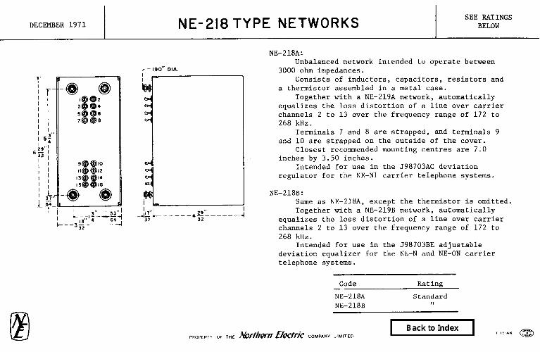
NE-218A: Unbalanced network intended to operate between
3000 ohm impedances. -I Consists of inductors, capacitors, resistors and
a thermistor assembled in a metal case. Together with a NE-219A network, automatically
equalizes the loss distortion of a line over carrier channels 2 to 13 over the frequency range of 172 to 268 kHz.
Terminals 7 and 8 are strapped, and terminals 9 and 10 are strapped on the outside of the cover.
Closest recommended mounting centres are 7.0 inches by 3.50 inches.
Intended for use in the J98703AC deviation regulator for the NE-N1 carrier telephone systems.
I NE-218B: Same as NE-218A, except the thermistor is omitted. Together with a NE-219B network, automatically
equalizes the loss distortion of a line over carrier channels 2 to 13 over the frequency range of 172 to 268 kHz.
Intended for use in the J98703BE adjustable deviation equalizer for the NE-N and NE-ON carrier telephone systems.
Code Rating
NE-218A NE-218B
Standard 11

DECEMBER 1971 NE-219 TYPE NETWORKS SEE RATINGS BELOW
NE-219A: Unbalanced network intended to operate between
3000 ohm impedances. Consists of inductors, capacitors, resistors and
a thermistor assembled in a metal case. Together with a NE-218A network, automatically
equalizes the loss distortion of a line over carrier channels 2 to 13 over the frequency range of 172 to 268 kHz.
Terminals 7 and 8 are strapped, and terminals 9 and 10 are strapped on the outside of the cover.
Closest recommended mounting centres are 7.0 inches by 3.50 inches.
Intended for use in the J98703AC deviation regulator for the NE-N1 carrier telephone systems.
NE-219B: Same as NE-21VA, except the thermistor is omitted. Together with a NE-218B network, automatically
equalizes the loss distortion of a line over carrier channels 2 to 13 over the frequency range of 172 to 268 kHz.
Intended for use in the J98703BE adjustable deviation equalizer for the NE-N and NE-ON carrier telephone systems.
Code Rating
NE-219A NE-219B
Standard 11

FEBRUARY 1972 NE-223 TYPE NETWORKS SEE RATINGS BELOW
I I
Each consists of inductors, capacitors, resistors, etc, assembled in a metal case on both sides of a metal panel arranged for rack mounting.
NE-223A:
Consists of two impedance arms, one being for use with the odd group filters and the other with the even group filters. The network is used to annul the susceptance of each group of paralleled filters, in order that a resistive impedance of approximately 72 ohms may be obtained across the band of each filter.
Intended for use with the group band filter in the L type carrier telephone system.
NE-223D and NE-223E:
Each consists of series resonant circuits in parallel and connects in shunt with the parallel side of the (even for NE-223D and odd for NE-223E) supergroup band filters in order that a resistive impedance of approximately 75 ohms may be obtained across the band of each filter and at the pilot frequencies.
Intended for use with the supergroup band filters in the L type carrier telephone system.
@
NE-223A NE-223D NE-223E
Standard II ,I
Code Rating

FEBRUARY 1972 NE-226 TYPE NETWORKS (Card 1)
4-
r 29/3 I
FIG 1
Each consists of apparatus such as capacitors, inductors, and resistors, mounted in a metal case.
Closest recommended mounting centres are 3.50 inches by 1.750 inches.

FEBRUARY 1972 NE-226 TYPE NETWORKS (Card 2)
SEE RATINGS BELOW
NE-226A: Intended to operate in shunt across the line at the paralleled end of the channel filters in the A2 or A3B
channel bank as an impedance correcting network. Intended for use in the terminal equipment for types .I, K, and L broad band carrier telephone systems.
NE-226B: Intended for use as a restoring network in the 5640818 monitoring ocsilloscope in the television video
transmission system. NE-226F:
Intended to operate between 75 ohm impedances introducing a peak of attenuation at 3.15 MHz. Intended for use in receiving television line of Ll carrier telephone system.
NE-226.J: Intended to operate between 75 ohm resistances at frequencies up to 4.5 MHz. Intended for use as a predistorter in connection with video transmission over the NTD-2 radio system.
NE-226K & NE-226L: Intended to operate between 124 ohm resistances, balanced-to-ground, at frequencies up to 5 MHz in the television
terminals of the NTD-2 radio system. NE-226K:
Intended for use as a restoring network. NE-226L:
Intended for use as a preemphasis network.
Code Figure Rating -
(a)NE-226A 1 NE-226B 3 NE-226F 3
(b)NE-226.J 3 NE-226K 2 NE-226L 2
(a) Hermetically sealed. (b) Unbalanced network.

NOVEMBER 1969 NE- 425Q TYPE NETWORKS (Card 1)
El (G IR I
I I NE-42SQD, ALSO GENERAL DESIGN
AND DIMENSIONS OF NE-4250 TYPE
I I 1 I
NE-425QF TYPE
(OTHERWISE SAME AS NE-425Q TYPE)

NOVEMBER 1969 NE-4250 TYYE NETWORKS
FIG. 3
6

NOVEMBER 1977 NE-4250 TYPE NETWORKS
(card 4) SEE RATINGS
BELOW
NE-425QGl: Same as NE-425QEl except that the 22 ohm resistor to terminal B is omitted. Forms part of TC-1000 transmission circuit when used with an NE-TlQC transmitter
unit and an NE-U1 receiver unit in a ME-804 telephone set.
NE-425QG2: Tropicalized version of the NE-425QGl network.
NE-425QHl: Same as NE-425QGl except that value of capacitor C4 is 0.8 PF.
NE-425QH2: Tropicalized version of the NE-425QHl.
NE-425QJl: For application with TC 1000 Transmission Circuit, using an NE-JAQBA 1.8 microfarad
capacitor. Initial Use: NEI-500DQB and NEI-554BQC Telephone Sets.
NE-425QJ2: Tropicalized version of NE-425QJl in that transformer coil is varnish chipped
and nickel plated screws are used on the terminal plate. For use with TlQC 1000 Transmission circuit in QSKBOOE Telephone Sets.
CODE FIG BATING
NE-425QGl 4 NE-425QG2 4 NE-425QHl 4 NE-425QH2 4 NE-42SQJl 4 NE-425QJ2 4
Standard ,I l, II ,I ,I
P~D~~R~y OF Northern Telecom Limited

NOVEMBER 1969 Nif-4250 TYPE NETWORKS (Card 3)
SEE RATINGS BELOW
Each consists of a transformer, capacitors, resistors and varistors potted in a plastic case.
Intended to provide the transmission circuit elements, including the sidetone balancing network, for an anti-sidetone telephone set. Also provides transmission equalization for varying loop lengths. Includes a ringing capacitor, dial radio interference suppression filter and terminal plate.
NE-425QDl: Forms part of NE-688AN subscriber sets and NE-3C type telephone consoles.
NE-425QEl: Forms part of NE-500 and NE-554 type telephone sets.
NE-425QE2: Tropicalized version of the NE-425QEl network.
NE-425QE3: Same as NE-425QEl except contains two additional capacitors for elimination of radio frequency interference. May be substituted for NE-425QEl network in high radio frequency interference locations.
NE-425QFl: Forms part of NE-500QlA and NE-554QU type telephone sets.
NE-
El
,425QFZ: Tropicalized version of the NE-425QFl network. Forms part of NE-500QB and NE-544QB type telephone sets.
Code Fig. Rating Code Fig. Rating Code Fig. Rating
NE-425QDl 1 Standard NE-425QE2 2 Standard NE-425QFl 3 Standard
NE-425QEl 2 II NE-425QE3 2 II NE-425QF2 3 tt

DECEMBER 1971 NE-426A NETWORK STANDARD
Consists of four toroidal type coils, each wound on a permalloy powder core, capacitors, and resistors potted in a metal case. Has a removable cover permitting access to thirty-six terminals which are for strapping purposes only.
Intended to operate as a balancing network over the voice frequency range.
Closest recommended mounting centres are 1.750 inches by 4.0 inches.
Intended for use in the NE-El telephone repeater, per 598611, for local exchange area circuits.

DECEMBER 1972 NE-430 TYPE NETWORKS SEE RATINGS BELOW
Each consists of apparatus such as transformers, inductors, and capacitors assembled in a metal case and arranged for single side mounting.
Mounting nuts and washers are furnished.
Provision is made for the adjustment of the inductance over a limited range by means of an adjustable magnetic core.
Approximate overall dimensions excluding the terminals and mounting studs are 1.438 inches by 1.562 inches by 2.750 inches high.
NE-43DW & Y:
Intended for use in the 568349B Ll & 2, Channel Initiators for the NTD-2 Radio Relay System.
NE-430AD & AE:
Intended for use in the 564047C receiving unit of the 564047A transmission measuring system.
NE-430AF:
Intended for use in the NE-71C test set.
Code Rating
NE-430W NE-430Y NE-430AD NE-430AE NE-430AF
Standard II 8, II II

FEBRUARY 1972 I NE-435 TYPE NETWORKS
FIG 2
Each consists of apparatus such as resistors, capacitors, and inductors potted in a metal case.
Closest recommended mounting centres are 1.750 inches by 2.625 inches.
Intended for use in amplifiers in the K2 carrier telephone system.

FEBRUARY 1972 NE-435 TYPE NETWORKS (Card 2)
SEE RATINGS BELOW
NE-435A and NE-435B:
Interstage networks for use in line, twist, and transmitting amplifiers.
Intended to operate over the frequency range of 12 to 60 kHz.
NE-435C:
Pilot network for use in the transmitting amplifier.
Intended to operate at a frequency of 60 kHz.
NE-435D:
Pilot supply network for use in the transmitting amplifier.
Intended to operate at a frequency of 60 kHz.
NE-435E:
Interstage network for use in the twist amplifier.
Intended to operate over the frequency range of 12 to 60 kHz.
Code Fig Terminals Rating
NE-435A 1 NE-435B 1 NE-435C 2 NE-435D 2
NE-435E 1
2, 3. 4, 5 Standard 1, 2, 3, 4, 5, 6 ,I 1, 2, 5, 6, 9 11 1, 2, 5, 6, 9, 10 II
2, 3, 4, 5
FEBRUARY 1972 NE-442A NETWORK
-
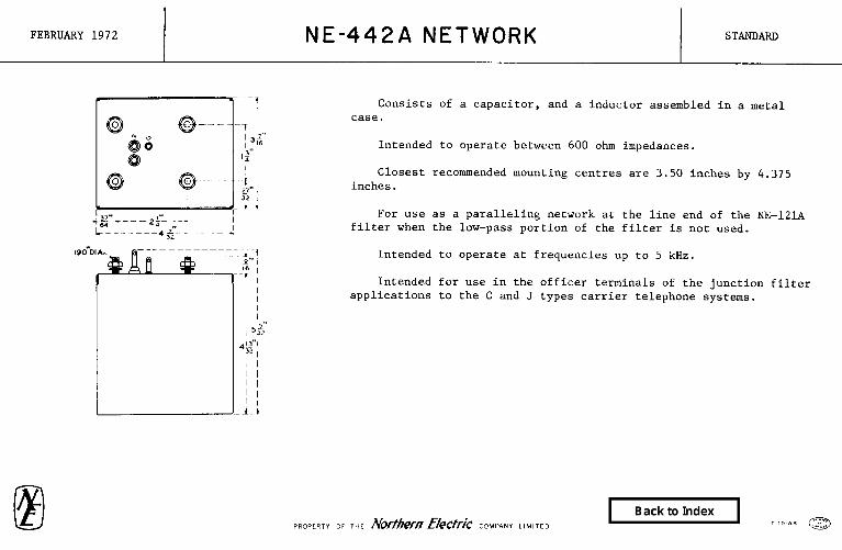
Consists of a capacitor, and a inductor assembled in a metal case.
Intended to operate between 600 ohm impedances.
Closest recommended mounting centres are 3.50 inches by 4.375 inches.
For use as a paralleling network at the line end of the NE-12lA filter when the low-pass portion of the filter is not used.
Intended to operate at frequencies up to 5 kHz.
Intended for use in the officer terminals of the junction filter applications to the C and J types carrier telephone systems.
/ I 1 I 1-L

JANUARY 1965 Nos. 442A & B NETWORKS SEE RATINGS BELOW
Each consists of a condenser and a retardation coil assembled in a metal can.
Intended to operate hctwecn 600 ohm impedances.
Closest recommended mounting centers are 3-l/2 inches by 4-3/8 inches.
Intended for U:X in the office terminals of the junction filter applications to the types C and J carrier telephone systems.
Xo. 442A : Paralleling network for use at the line end of the No. 52A filter when its complementary No. 5lA filter is not used or as a paralleling network at the line end of the No. 141A filter when the low- pass portion of the filter is not used. Intended to operate at frequencies up to 5 KC.
No. 442B : Paralleling network for use at the line end of the No. 34.l filter when its complementary No. 36B filter is not used. Intended to operate at frequencies up to 3 KC.
Code No.
442A 442B
Replaces ---~-~~
Rating
Standard “

DECEMBER 1971 NE-443A NETWORK STANDARD
I3.’ -. .~ _ _ _ ~. -~‘Oz---- ’ 37- *. I ‘&y- 9; Balanced network intended to operate over
f - - --I the frequency range of 4.8 to 145 hertz.
-I Intended to operate as an impedance
correcting network between impedances of 13, 16 or 19 gauge non-loaded entrance cable pairs and the input impedance of a NE-102A filter.
Consists of inductors and capacitors assembled in a metal case.
Closest recommended mounting centres are 10.50 inches by 3.50 inches.
Intended for use in the office terminals of the junction filter applications to the type NE-C and NE-J carrier telephone systems.

DECEMBER 1971 NE-445A NETWORK STANDARD
.164”DI
Paralleling network for use at the line end of the low-pass portion of the NE-12l.A filter when its complementary high-pass portion is not used.
Consists of capacitors and inductors potted in a metal case.
j / I ; I '
Intended to operate over the frequency range of 5 to 150 kHz.
Closest recommended mounting centres are 1.750 inches by 3.50 inches.
Intended for use in the office terminals of the junction filter applications to the type NE-C and NE-J carrier telephone systems.

MAY 1972 NE-451 TYPE NETWORKS SEE RATlNGS BELOW
I (Card 1) I
Each consists of inductors and capacitors assembled in a metal case.
Approximate overall dimensions are 0.781 inches by 1.406 inches by 3.406 inches high, not including the terminals.
NE-451A TO NE-453DK:
Intended for use in the NE-43Al carrier telegraph system.
NE-45lDL TO NE-451DP:
Intended for use in the NE-202E and F filters for use in the Sage project.
Used In Code Network Rating
NE-451A NE-454N Standard NE-451B NE-454N II
NE-451C NE-454N II
NE-451D NE-454N II
NE-451E NE-454P II
NE-451F NE-454P II
NE-451G NE-454P II
NE-451H NE-454P II
NE-451.J NE-454R 1,
NE-451K NE-454R 91
NE-451L NE-454R 0
NE-451M NE-454R II
NE-451N NE-454s II
NE-451P NE-454s ,e
NE-451R NE-454S .I
Used In Code Network Rating
__-
NE-451s NE-454s Standard NE-451T NE-454T I,
NE-454U NE-454T ,I
NE-454W NE-454T II
NE-454Y NE-454T 9,
NE-454AA NE-454U 11
NE-454AB NE-454U II
NE-454AC NE-454U 1,
NE-454AD NE-454U II
NE-454AE NE-453N II
NE-454AF NE-453P ,,
NE-454AG NE-453R 11
NE-454AH NE-453s $1
NE-454AJ NE-453T I,
NE-454AK NE-453U II
Code
NE-451AL NE-451AM NE-451AN NE-451AP NE-451AR NE-451AS NE-451AT NE-451AU NE-451AW NE-451AY NE-451BA NE-451BB NE-451BC NE-451BD NE-451BE
Used In Network
-.- NE-453G NE-453H NE-453s NE-453K NE-453L NE-453M NE-454G NE-454s NE-454G NE-454G NE-454H NE-454H NE-454H NE-454H NE-454.7

MAY 1972 NE-451 TYPE NETWORKS (Card 21
Code
NE-451BF NE-451BG NE-451BH NE-451BJ NE-451BK NE-451BL NE-451BM NE-451BN NE-451BP NE-451BR NE-451BS NE-451BT NE-451BU NE-451BW NE-451BY NE-451CA NE-451CB
Used In Network Rating
NE-454J Standard NE-454.l II
NE-454J II
NE-454K 1,
NE-454K II
NE-454K II
NE-454K II
NE-454L II
NE-454L ,!
NE-454L II
NE-454L ,I
NE-454M 0
NE-454M 1,
NE-454M I*
NE-454M 11
NE-453AD II
NE-453AC II
Used In Code Network Rating
NE-451CC NE-453AB Standard NE-451CD NE-453AA 11
NE-451CE NE-454AD II
NE-451CF NE-454AD 11
NE-451CG NE-454AD II
NE-451CH NE-454AD ,,
NE-451CJ NE-454AC II
NE-451CK NE-454AC II
NE-451CL NE-454AC II
NE-4510~ NE-454AC II
NE-451CN NE-454AB II
NE-451CP NE-454AB II
NE-451CR NE-454AB 4,
NE-451CS NE-454AB 1,
NE-451CT NE-454AA *,
NE-451CU NE-454AA II
SEE RATINGS BELOW
Used In Code Network Rating
NE-451CW NE-454AA Standard NE-451CY NE-454AA 8,
NE-451DA NE-454Y II NE-451DB NE-454Y ,u
NE-451DC NE-454Y I#
NE-451DD NE-454Y ,I
NE-451DE NE-454W 1,
NE-451DF NE-454W ,I
NE-451DG NE-454W 11
NE-451DH NE-454W II
NE-451DJ NE-453Y II
NE-451DK NE-453W II
NE-451DL 11
NE-451DM 1,
NE-451DN II
NE-451DP II

MAY 1972 NE-452 TYPE NETWORKS SEE RATINGS BELOW
I I
Each consists of an inductor assembled in a metal case, and an external capacitor. The core material of the inductor is molybdenum permalloy powder.
Approximate overall dimensions of the case which houses the inductor, not including the terminals, are 0.781 inch by 1.406 inch by 3.406 inch high. The terminals extend the overall height to approximatley 3.781 inches.
NE-452A TO NE-452U:
Intended for use in networks for the 43Al carrier telegraph system.
NE-452W TO NE-452AB:
Intended for use in the NE-202E and NE-202F filters for the sage project.
Code Used In Network Rating Code
Used In Network Rating
NE-452A NE-452B NE-452C NE-452D NE-452E NE-452F NE-452G NE-452H NE-452J NE-452K NE-452L
NE-453N NE-453P NE-453R NE-453s NE-453T NE-453U NE-457G NE-453H NE-453J NE-453K NE-453L
NE-452M NE-452N NE-452P NE-452R NE-452s NE-452T NE-452U NE-452W NE-452Y NE-452AA NE-452AB
NE-453M NE-453AD NE-453AC NE-453AB NE-453AA NE-453Y NE-453W
Standard II 8, ,, 8, 0, ,, ,, II II II

453 TYPE NETW6RKS (Card 1)
Each consists of resistors, capacitors, inductors, transformer, potentiometer and male connector assembled in a metal can.
Each comprises an oscillator network and a band-pass filter which is intended to pass frequencies in the range indicated on card 2. The filter is designed to operate from an electron tube plate impedance of 7500 ohms into a 600 ohm unbalanced circuit.
Terminals 5, 6 and 7 on the terminal strip are intended for strapping purposes only.
Closest recommended mounting centers are l-9/16 inches by 7-15/16 inches.
Intended for use as sending networks in the 43Al Car- rier Telegraph System.

453 TYPE. NETWORKS SEE RATINGS JULY 1968 BELOW
(Card 2)
Code Frequency Range (QPS) Ratfngs Code Frequency Range (CPS) Ratings
4538 453B 453c
453D 453E 453F 453G 4531 4535 453K 4532, 453M
453N 4531 453R
453s
560-630 730-800 900-970
1070-1140 1240-1310 1410-1480
1750-1820 1920-1990 zo9o-2160 2260-2330 2430-2500 2600-2670
3910-3990 4110-4190 4315-4405 4535-4625
453T 453u 453w 453Y 453AA 453AB 453AC 453AD 453AB 453QlAl 453QlA2 453QlA3 453QlA4
453QlA5 4534116
4760-4860 5000-5100 3510-3590 3710-3790 1580-1650 2770-2840 2940-3010 3110-3180
390-460 1290-1430 1630-1770 1970-2110 2310-2450 2650-2790 2990-3130

SEPTEMBER 1966 454 TYPE NETWORKS (Card 1)
1 32
4.656
I
Each consists of resistors, capacitors, inductors, transformer and male connector assembled in a metal can.
Each comprises a discriminator and a band- pass filter which is intended to pass frequenc- ies in the range indicated on card 2. The filter is designed to operate from a 600 ohm unbalanced circuit into a 140,000 olm~ electron tube grid circuit. A 140,000 ohm terminating resistor is provided within the network.
Closest recormnended mounting centers are l-9/16 inches by 7-15/16 inches.
Intended for use as receiving networks in the 43Al Carrier Telegraph System.

JULY 1968 454 TYPE NETWORKS SEE RATINGS (Card 2) BELOW
Code Frequency Range (CPS) Rating Code Frequency Range (U'S) Rating
454A 560-630 Standard 454T 4760-4860 Standard 454B 730-800 1, 454u 5000-5100 ,I 454c 900-970 11 454w 3510-3590 II 454D 1070-1140 II 45471 3710-3790 11 4543 1240-1310 I, 454AA 1580-1650 0, 454F 1410-1480 II 454AB 2770-2840 II 454G 1750-1820 11 454AC 2940-3010 a, 454H 1920-1990 ,I 454AD 3110-3180 tt 4545 2090-2160 11 454AE 390-460 II 454K 2260-2330 1, 4544181 1290-1430 Mfr. Disc. 454L 2430-2500 11 454QlA2 1630-1770 II 454M 2600-2670 11 454QlA3 1970-2110 11 454N 3910-3990 ,I 454QlA4 2310-2450 11 454P 4110-4190 II 454QlA5 2650-2790 II 454R 4315-4405 I, 454QlA6 2990-3130 II 454s 4535-4625 II

DECEMBER 1971 NE-455 TYPE NETWORKS SEE RATINGS BELOW
Unbalanced networks intended to operate between 600 ohm impedances.
Each consists of inductors, capacitors, and resistors assembled in a metal case and terminated in a plug-type connector.
Closest recommended mounting centres are 3.50 inches by 5.250 inches.
Intended for use with NE-201A noise generator.
NE-455A:
Intended to provide 15 kRz program weighting.
Terminals 7 and 8 are electrically common. There are no electrical connections to terminals 2, 3, 4, and 6.
NE-455B:
Intended to provide FlA transmitter weighting.
Terminals 2, 3, 4 and 8 are electrically common. There are no electrical connections to terminals 6 and 7.
Code Rating
NE-455A NE-455B
Standard II

DECEMBER 1971 NE-456 TYPE NETWORKS SEE RATINGS BELOW
I I
?El
pie 0
Ogm-$ 09 I I
;&-------5$:- ------- 4
______ ---6;.l--- ---------
-- T
-4 ,I- ," 2 5 ' 7-L
Unbalanced regulating networks each interlded to operate between 75 ohm impedances at the frequency listed in the table below.
Each consists of a resistor, inductors, and capacitors assembled in a metal case.
1
Closest recommended mounting centres are 1.750 inches
NE - 456 TYPE FOR NUMBER OF TERMINALS,
SEE TEXT
-T. by 7.0 inches.
Intended for use as pilot networks in the 568783A twist amplifier of the NE-K2 cable carrier telephone system.
Code
NE-456A
Terminals Frequency
&Hz)
12
Rating
Standard
NE-456B [i: ;;l~~,411,) 28 ”

DECEMBER 1971 NE-457 TYPE NETWORKS SEE RATINGS BELOW
Unbalanced networks intended to operate between 75 ohm impedances.
Each consists of a capacitor, an inductor and resistors assembled in a metal case. The input is terminated in a NE-470B jack and the output in a coaxial connector which is arranged for use with an NE-477 type jack. The outer contacts of the jack and connector are grounded to the case.
Closest recommended mounting centres are 3.50 inches by 1.750 inches.
Intended to provide predistortion and restoration, respectively, of message channels at interconnections between NE-TD-2 radio systems and NE-L1 carrier telephone equipment.
Code
NE-457A NE-457B
Rating
Standard 11

I Nos.459A, B & C NETWORKS I SEE RATINGS
JANUARY 1965 BELOW
A~.’ ! ‘:
Unbalanced line building-out networks intended to operate between 75 ohm impedances over the frequency range 50 to 3100 KC.
Bach consists of apparatus such as resistances, capacitors and retarda- tion coils assembled in a metal case. Equipped with two No. 724 cables for input and output terminations. The input. cable ,is terminated in a No. 466B jack and the output cable is termmated m a No. 337B plug. The outer contluctor.s of the jack and plug are electrrcally com- mon with the case.
Intended to simulate the ral~le length of .U ?75 inch coaxial cable as indicated in the table.
Closest recommended mounting centers are 3-l/2 inches by 3-l/2 inches. Intended for use in the JG8791 auxiliary repeater equipment of the Ll
carrier telephone system.
Cable Code Length Simulated No. (Miles) __. ~_~ .- --
Replaces - Rptina
45911 .35 459B .7 459c 1.4
NOT MANUFACTURED Standard
NOT MANUFACTURED

FEBRUARY 1972 NE-4596 NETWORK STANDARD
Consists of resistors, capacitors, and inductors assembled in a metal case.
Equipped with two NE-724 cables for input and output terminations. The input cable is terminated in a NE-466B jack and the output cable is terminated in a NE-358A plug. The outer conductors of the jack and plug are electrically common with the case.
Unbalanced line building-out network intended to operate between 75 ohm impedances over the frequency range 50 to 3100 kHz.
Closest recommended mounting centres are 3.50 inches by 3.50 inches.
Intended to simulate .7 mile of the cable length of .375 inch coaxial cable.
Intended for use in the 568791 auxiliary repeater equipment of the Ll carrier telephone system.

DECEMBER 1971 NE-460A NETWORK STANDARD
Consists of a coil and a capacitor assembled in a metal case. The capacitor and coil are connected in parallel across terminals 1 and 3.
Inductance may be varied over a limited range, through a hole in the bottom of the case by means of an adjustable ferrite core.
Nominal inductance is 42.6 microhenries.
Intended for use in the 564037A transmission measuring set in the NE-L.3 carrier telephone system.

DECEMBER 1971 NE-461 A NETWORK STANDARD
Consists of a coil and capacitors assembled in a metal case having a cover of insulating material.
The coil and capacitors are connected in parallel between terminals 1 and 2.
Nominal inductance is 1.34 microhenries.
Inductance may be varied over a limited range, through a hole in one end of the case, by means of an adjustable ferrite core.
Intended for use in the 5640378 transmission measuring set in the NE-L3 carrier telephone system.

DECEMBER 1971 NE-463 C NETWORK STANDARD
Unbalanced variable phase shifter consisting of inductors, capacitors, resistors, and a two-gang variable capacitor assembled in a metal case.
Closest recommended mounting centres are 3.250 inches by 2.50 inches.
Intended to operate between 75 ohm impedances at a frequency of 3.579 MHz.
Intended for use in the J64047C receiving unit of the J64047A transmission measuring system.

MAY 1972 NE-467A NETWORK
Consists of two winding assemblies having ferrite cores and of associated capacitors in a rectangular metal case with a moulded plate assembly as the cover. It is arranged for stud mounting and mounting nuts and washers are furnished. The mounting studs are on the same side as rod type terminals.
Approximate overall dimensions are 1.484 inches by 2.00 inches by 2.188 inches high, not including the mounting studs and terminals.
The nominal inductance, measured at 50 kHz between terminals 1 and 2 and between terminals 3 and 4,‘is 2065 microhenries. Terminal 5 and 6 are centre taps of windings (l-2) and (3-4), respectively.
Intended for use in the NE-522H filter for the L3 carrier system.

DECEMBER 1971 NE-469 TYPE NETWORKS SEE RATINGS BELOW
Inter-stage networks intended to operate between the grid and plate of two 6SJ7 electron tubes.
Each consists of capacitors and an inductor assembled in a metal case.
Closest recommended mounting centres are 1.750 inches by 1.750 inches.
NE-469A differs from NE-469B in that it has an increased capacitance to allow for the absorption in external circuits.
Intended for use in the 564031B transmission measuring set in type NE-K2 carrier telephone systems.
Code Ratine
NE-469A NE-469B
Standard ,t

DECEMBER 1971 NE-472A NETWORK STANDARD
Balanced, impedance matching network, intended to operate between frequencies of 1 kRz and 8 MHz.
Consists of resistors, and capacitors assembled in a metal case and terminated in two NE-470B jacks, the outer contacts of which are electrically connected to the case. The jacks are arranged to accommodate a 5441038 video mounting probe. Also provided with two pairs of pin jacks, each pair of which is arranged to accormnodate a NE-395A plug. The jacks are located on the end opposite the mounting end.
Closest recommended mounting centres are 3.50 inches by 3.50 inches.
Intended to match the 16 PSVL cable terminations in the NE-A2A and NE-A2B video systems.

DECEMBER 1971 NE-474 TYPE NETWORKS SEE RATINGS BELOW
ji
NE.474A ALSO GENERAL DESIGN AND
DIMENSIONS OFNE- 474 TYPE
Each consists of an inductor, a variable capacitor and fixed capacitors assembled in a housing of insulating material and terminated in two plug fingers which are arranged for connection to NS14523 connectors.
Each is intended for use in aligning and checking circuits of the 544105 amplifiers of the NE-A2A and NE-A2B video transmission systems.
Dimensions (Inches)
Code A B Rating
NE-474A 3.50 .750 NE-474B 3.00 .438
Standard II

FEBRUARY 1972 NE-479A 81 NE-480A NETWORKS SEE RATINGS BELOW
FIG I FIG 2
(OTHERWISE SAME AS FIG 11
Balanced networks each intended to operate between a 16 gauge PSVL cable impedance and 4460 ohms over the frequency range of 30 hertz to 4.5 MHz.
Consists of apparatus such as inductors, capacitors, resistors, and a transformer assembled in a metal case. Closest recommended mounting centres are 3.50 inches by 5.250 inches.
NE-479A: Provided with four NS14523 Ll connectors on bottom of case for testing purposes. Intended for use as an output
network in the 5441058 network output amplifier of the A2A video transmission system. NE-480A:
Equipped with two coaxial connectors which are arranged for connection to 16 gauge PSVL cable. Intended for use
as an input network in the 5441056 network input amplifier of the A2A video transmission system.
Code Figure Rating
NE-479A 1 Standard NE-480A 2 II
PRowmY or THE Norrhem E/ictric TYMPANY LIMITED

DECEMBER 1971 NE-483 TYPE NETWORKS SEE RATINGS BELOW
.164”;32 THREAD
nJ LB FIG 2
FIG A Code Fig Capacitor Resistor Figure Rating
.c c-0
NE-~WA.ALSO GENERAL DESIGN FIG B AND DIMENSIONS OF NE -403 TYPE
Each consists of one or two capacitors and one or two resistors potted in a metal case having a cover of insulating material.
Tested on 600 volts dc between terminals. Suitable for use on continuously applied potentials not
exceeding 200 volts dc or impulse voltages not exceeding 300 volts peak, at a rate not exceeding 50 pulses per second, and at operating temperatures between -60°F and +170°F.
Closest recommended mounting centres are .50 inches by 1.50 inches.
NE-483A: Intended for use in the J41611N and J41611Y radio
transmitter panels of the LD-T2 radio system. NE-483C, D, & E:
Intended for use in the 586465 power plants.
Contains Schematic
I
NE-483A 1 1.00 uF 160 Ohms A Standard NE-483C 1 0.50 nF 1000 Ohms A II
(a)NE-483D 2 0.50 nF 510 Ohms II 0.50 nF 510 Ohms B
(a)NE-483E 2 0.50 nF 160 Ohms II 0.50 nF 160 Ohms B
(a) Mounting stud is electrically connected to the case.

FEBRUARY 1972 NE-484 TYPE NETWORKS SEE RATINGS BELOW
I” Balanced networks each consisting of inductors and capacitors assembled in a metal case.
Provided with terminal leads approximately 6 inches
;,jfTy$ i======Tp long* Intended to operate between 600 ohm impedances in
connection with a varistor modulator, a demodulator band filter and a demodulator amplifier to prevent
II 16 mutual interference between voice frequencies and I
,. FIG 2 carrier frequencies. I
c -2 1 ii
I-1 (OTHERikE S&ME
AS FIG.11 Closest recommended mounting centres are 2 inches by 2 inches.
Intended for use in J68734B and J68734C channel modem units for type J, K, and L carrier telephone
FIG I
11" 2ii
--i
systems.
Code
NE-484A NE-484B NE-484D NE-484E NE-484F
Fig
1 1 2 2 2
Channels Used With
1 5 and and 3 7 2 and 4 6 and 8
10 and 12
Rating
Standard II II II 1,

DECEMBER 1971 NE-485A NETWORK STANDARD
71 r 16 r 164’:32 THREAD
Balanced network consisting of inductors and capacitors assembled in a metal case.
Intended to provide impedance correction at the paralleled ends of NE-561A to M filters.
Closest recommended mounting centres are 1.750 inches by 1.750 inches.
Intended for use in the 568853B A5 channel bank multiplex terminal equipment for broadband carrier telephone systems.

DECEMBER 1971 NE-486 TYPE NETWORKS SEE RATINGS BELOW
NE-486A
@
NE- 4868 BCOTHERWISE SAME AS NE-486A
Adjustable networks, consisting of inductors, capacitors, and resistors assembled in a metal case.
Provision is made for tuning to the operating frequency through a hole in the bottom of the case.
Closest recommended mounting centres are 1.750 inches by 2.688 inches.
NE-486A & B:
Intended for use in the amplifer - detector of the SD-95810 identifier of common systems.
NE-486A:
Has a frequency band width of 250 hertz centred at 5800 hertz.
NE-486B:
Has a frequency band width of 130 hertz centred at 5800 hertz.
NE-486C:
Operates at a frequency of 5803 hertz.
Intended for use in the oscillator of the SD-95827 signal generator of the automatic number identification system.
Code
NE-486A NE-486B NE-486C
PROPER,Y OF THE Nortbem Hectric CO~~~~~ LIMITED
Rating
Standard II II

APRIL 1970 NE-487 TYPE NETWORKS
Consists of a coil and a capacitor encapsulated in a case of insulating material.
Closest recommended mounting centres are 1.500 inches by 1.500 inches.
JULY 1970 NE-487 TYPE NETWORKS (Card 2)
SEE RATINGS BELOW
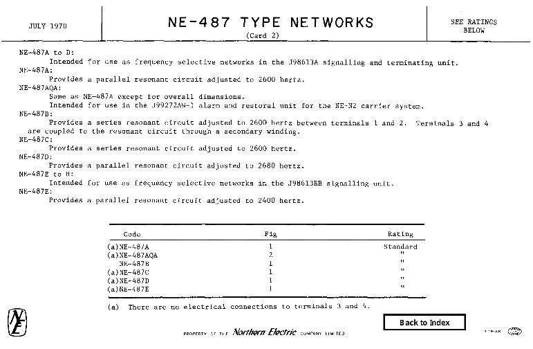
NE-487A to D: Intended for use as frequency selective networks in the 5986138 signalling and terminating unit,
NE-487A: Provides a parallel resonant circuit adjusted to 2600 hertz.
NE-487AQA: Same as NE-487A except for overall dimensions. Intended for use in the J99272AW-1 alarm and restoral unit for the NE-N2 carrier system.
NE-487B: Provides a series resonant circuit adjusted to 2600 hertz between terminals 1 and 2. Terminals 3 and 4
are coupled to the resonant circuit through a secondary winding. NE-487C:
Provides a series resonant circuit adjusted to 2600 hertz. NE-487D:
Provides a parallel resonant circuit adjusted to 2680 hertz. NE-487E to H:
Intended for use as frequency selective networks in the J98613BB signalling unit. NE-487E:
Provides a parallel resonant circuit adjusted to 2400 hertz.
Code Fig Rating
(a)NE-487A 1 Standard (a)NE-487AQA 2 11
NE-487B 1 11 (a)NE-487C 1 II (a)NE-487D 1 11 (a)NE-487E 1 ,a
(a) There are no electrical connections to terminals 3 and 4.

JULY 1970 NE-487 TYPE NETWORKS (Card 3)
SEE RATINGS BELOW
NE-487F: Provides a series resonant circuit adjusted to 2400 hertz between terminals 1 and 2. Terminals 3 and 4
are coupled to the resonant circuit through a secondary winding. NE-487G:
Provides a series resonant circuit adjusted to 2400 hertz. NE-487H:
Provides a parallel resonant circuit adjusted to 2465 hertz. NE-487J:
Same as NE-487B except that the polarity of the secondary winding (terminals 3 and 4) is reversed. Intended for use in the J98613D signalling unit.
NE-487JQA: Same as NE-487J except for overall dimensions. Intended for use in the J99272AW-1 alarm and restoral unit for the NE-N2 carrier system.
NE-487K: Same as NE-487F except that the polarity of the secondary winding (terminals 3 and 4) is reversed. Intended for use in the J98613BE signalling unit.
NE-487L: Same as NE-487A except has a lower conductance. Intended for use in the J99262M1, J99262N1, J99262Pl and J99262Rl order wire and alarm circuits for the
TL radio system.
Code Fig Rating Code Fig Rating
NE-487F 1 Standard NE-487JQA 2 Standard (a)NE-487G 1 11 NE-487K 1 II
(a)NE-487H 1 11 (a)NE-487L 1 ,I NE-487J 1 II
(a) There are not electrical connections to terminals 3 and 4.

JUNE 1971 NE-495A NETWORK STANDARD
Consists of a transformer, capacitors, resistors and varistors potted in a metal case.
Intended to provide the transmission circuit elements, including the sidetone balancing network, for an anti-sidetone telephone set. Also provides transmission equalization for varying loop lengths. Includes a dial radio-interference suppression filter and connecting block.
Forms a part of the NE-701 and NE-711B telephone set.

NO. 496A NETWORK STANDARD JANUARY 1965
km---------------- . .
,g ------- -------*
l ’ I .I
!&~~---------,8; __-~---------_--
I
-* I
I I 1 I
r-.=-F--- , I1

SEE RATINGS AUGUST 1976 BELOW
NE-497 TYPE NETWORKS
Each is an unbalanced 600 ohm plug-in network consisting of capacitors, resistors and inductors mounted on printed wiring boards and potted in a metal shield.
Terminated in a NS16425 L4 connector.
Approximate over-all dimensions are 5.34 inches by 2.80 inches by 1.12 inches.
Choice of weighting characteristic or flat characteristic on NE-497A & NE-497B networks is made by rotating network 180° in the associated connector.
Intended for use in 394003A noise measuring set.
NE-497A: Provides a "message weighting" characteristic similar to the FlA weighting characteristic, and
a "3 kHz flat" characteristic.
NE-497B:
Provides a "program weighting" characteristic and a "15 kHz flat" characteristic.
NE-497E:
Intended for use in the 394006H and J94006HR test sets.
NE-497G:
Intended for use in the 3940068 and J94006HR impulse counters.
CODE RATING
NE-497A Standard NE-49 JB Standard NE-497E Standard NE-497G Standard
PROPERTY Or Northern Telecom Limited

JUNE 1971 NE-498A NETWORK STANDARD
d” ,‘\\\
Consists of capacitors, a diode and a reeistor assembled on a terminal plate and potted in a metal case.
Provides circuit elements for both chime and ringer operation.
Forms part of the QCYlAl and QCYlA2 bell chimes.

DECEMBER 1971 NE-806 TYPE NETWORKS SEE RATINGS BELOW
Each consists of a printed wiring board on which is mounted inductors, capcitors, and resistors.
Each is a single frequency balanced band- pass filter intended to operate between a sending impedance of 600 ohms and a receiving impedance of 120,000 ohms.
NE-806A:
Intended to pass a frequency of 1600 hertz and attenuate all other frequencies.
Intended for use as a timing filter in the JlGOOOG digital data transmitter of the SAGE system.
NE-806B:
Intended to pass a frequency of 1300 hertz and attenuate all other frequencies.
Intended for use as a timing filter in the JlGOOOR digital data transmitter of the SAGE system.
Code Ratine
NE-806A NE-806B
Standard II

DECEMBER 1971 NE-807A NETWORK
Balanced band-pass filter intended to operate between 600 ohm terminations contains a 6 db balanced pad.
Consists of inductors, capacitors, and resistors mounted on a printed wiring board.
Intended to pass a band of frequencies from 800 to 3300 hertz and attenuate all other frequencies.
Intended for use as a noise suppression filter in the JlGOOOG and JlGOOOR digital data transmitters.

DECEMBER 1971 NE-808 TYPE NETWORKS SEE RATINGS BELOW
Each is an unbalanced network intended to operate between 20,000 ohm terminations.
Consists of inductors, capacitors and resistors mounted on a printed wiring board.
NE-808B:
Low-pass filter intended to pass all frequencies below 800 hertz and attenuate all other frequencies.
Intended for use in shaping the tranmission loss characteristics for the 1300 hertz circuit in the JlGOOOR digital data transmitters.
NE-808C:
Low-pass filter intended to pass all frequencies below 800 hertz and attenuate all othe frequencies.
Intended for use in shaping the transmission loss characteristics for the 1600 hertz circuit in the JlGOOOG digital data transmitter.
Code Ratinn
NE-808B NE-808C
Standard 11

DECEMBER 1971 NE-809 TYPE NETWORKS SEE RATINGS BELOW
I I
Each is a low-pass receiving filter intended to operate between 40,000 ohm terminations.
Consists of inductors, capacitors, and resistors mounted on a printed wiring board.
Intended for use in the JlGOOOH digital data receiver.
NE-809A:
Intened to pass frequencies below 900 hertz and attenuate all other frequencies. Approaches a constant resistance at terminals 1-2.
NE-809B:
Intended to pass frequencies below 900 hertz and attenuate all other frequencies.
Code Rating
NE-809A NE-809B
Standard II

DECEMBER 1971 NE-810 TYPE NETWORKS SEE RATINGS BELOW
Each is a balanced equalizer intended to operate between 600 ohm terminations and provide delay equalization over the frequency range of 800 to 2400 hertz.
Consists of inductors, capacitors and resistors mounted on a printed wiring board.
NE-810B:
Intended for use in equalizing the delay characteristics of the 1300 hertz circuit of the JlGOGOR digital data transmitter.
Intended for use in equalizing the delay characteristics of the 1600 hertz circuit of the JlGOOOG digital data transmitter.
Code Rating
NE-810B NE-810C
Standard 8,

NE-811A NETWORK STANDARD
Vestigial sideband band-pass filter intended to operate between 600 ohm terminations.
Consists of inductors, capacitors, and resistors mounted on a printed wiring board.
Intended to pass a band of frequencies from 850 hertz to 2000 hertz and attenuate all other frequencies. Approaches a constant resistance at terminals 1 - 2.
Intended for use in the JlGOOOH digital data receiver.

DECEMBER 1971 NE-812 TYPE NETWORKS SEE RATINGS BELOW
I
Each is an unbalanced band-pass filter intended to operate between 100,000 ohm terminations. Consist of inductor and capacitors mounted on a printed wiring board.
NE-812A. ALSO GENERAL DESK?. -1.1 DIMENSIONS OFNE-812 TYPE
NE-812C & D:
Intended for use as timing filters for the 1600 hertz and 1300 hertz circuits respectively, of the JlGOOOH digital data receiver.
NE-812C:
Will pass a narrow band of frequencies centred at 1600 hertz and attenuate all other frequencies.
NE-812D:
Will pass a narrow band of frequencies centred at 1300 hertz and attenuate all other frequencies.
Code Rating
NE-812C NE-812D
Standard ,,

DECEMBER 1971 NE-813A NETWORK STANDARD
Consists of inductors and capacitors mounted on a printed wiring board.
Consists of two filter units connected in parallel at the 5000 ohm input end. One unit is intended to operate between a sending impedance of 5000 ohms and a receiving impedance of 40,000 ohms and pass a band of frequencies from 300 hertz to 600 hertz and attenuate all other frequencies. The other unit is intended to operate between a sending impedance of 5000 ohms and a receiving impedance of 100,000 ohms and pass a narrow band of frequencies centred at 2000 hertz and attenuate all other frequencies.
Intended for use as a trouble detecting filter in the JlGOOOJl trouble detecting circuit of the SAGE system.

DECEMBER 1971 NE-813C NETWORK STANDARD
Consists of resistors, capacitors, transformers, and
) '7" L ~I~~_ - ~- 4 -y== y_P
; -;
varistors, mounted on a printed wiring board. 64 . 1 -2
d 9"
4;' .I g lx* Intended for use as a part of the JlGOOOJ trouble detector unit.
- 1% - 2;' I,

DECEMBER 1971 NE-8148 NETWORK I STANDARD
N E-WA. ALSO GENERAL DESlGN AN‘, D\WNSlONSOFNE-814 TYPE
Consists of resistors, capacitors, and varistors mounted on a printed wiring board.
Intended for use as part of the digital data receiver circuit SD-lGOOl-01.

DECEMBER 1971 NE-815 TYPE NETWORK SEE RATINGS BELOW
~‘DIA
Each consists of capacitors, resistors, and diodes mounted on a printed wiring board.
Intended for use in NE-Al digital data signalling system.
Code Dimension A (Inches) Rating
NE-815A 1.250 NE-815B 1.250
Standard 11
NE-815C .547 II II NE-815D 1.250 II
NE-815E 1.234 ,I NE-815F 1.234 11 NE-815G 1.234 .391 II
NE-815H
NE-815A. ALSO GENERAL DESIGN AND DIMENSIONS OF NE-815 TYPE

DECEMBER 1971 NE-816 TYPE NETWORKS SEE RATINGS BELOW
I
Each consists of capacitors, resistors, diodes, etc, mounted on
I 5”
i G DIP.
a printed wiring board.. NE-816A:
Intended for use as part of the J98613A ElA signalling wire terminating unit of common systems.
NE-816B: Intended for use as part of the J98613D ElB 2600 hertz
unit for intertoll E and h circuits of common systems. NE-816C:
Intended for use as part of the J98613E ElC signalling wire terminating unit - originating, of common systems.
and four-
signalling
and four-
" NE-816H & .I: Intended for use as a part of the J98613BE transistorized single
frequency signalling unit for intertoll E and M circuits of common systems.
NE-816K: Intended for use as part of the J98613F List 2 ElD signalling and
four-wire terminating unit - terminating, of common systems. NE-816M:
Intended for use as part of the J98613BL ElL signalling and four- wire terminating unit of common systems.
NE-816N: Intended for use as part of the 598613BS ElS signalling and four-
w*re terminating unit or common systems. NE-816A ALSO GENERAL DESIGN AND DIMENSIONS OFNE-816 TYPE
PROPERT
Code Rating Code Rating ,
NE-816A Standard NE-816B II
NE-816C II
NE-816D II
NE-816H II
y OF THE Norfhem E/Qcric CWANY LIMITED
NE-816J NE-816K NE-816M WE-816N

FEBRUARY 1972 NE-818A TO NE-82lA NETWORKS SEE RATINGS BELOW
I I
Intended for use in the NE-756A PBX.
Each consists of capacitors, resistors, etc, mounted on a printed wiring board the terminal end of which is arranged to plug into the associated connector.
Approximate over-all dimensions are 4.0 inches long by 1.578 inches wide by depth as indicated in table,
NE-818A:
Intended for use in the 120 and 600 hertz oscillators of the 586464G transistor low tone supply,
NE-819A:
Intended for use in the voltage divider and modulator of the 586464G transistor low tone supply.
NE-820A:
Intended for use in the amplifier of the J86464G transistor low tone supply.
NE-821A:
Intended for use in the 20 hertz and 60 hertz oscillators of the J86464h transistor 20 hertz supply and the 5864645 transistor 60 hertz supply.
Code
NE-818A NE-819A NE-820A NE-82L4
Approximate Depth (Inch) Rating --- .____~--
.750 Standard
.562 II
.812 ,,
.812 1,

NE-822A TO NE-824A NETWORKS SEE RATINGS BELOW
NE-g22A & NE-823A: Intended for use in the NE-756A PBX. Each consists of capacitors, resistors, etc, mounted on a printed wiring board the terminal end of which is
arranged to plug into the associated connector. Approximate over-all dimensions are 4.00 inches long by 1.578 inches wide by depth as indicated in table.
NE-S22A: Intended for use in the 20 hertz and 60 hertz supplies of the 5864648 transistor 20 hertz supply and the
5864645 transistor 60 hertz supply. NE-823A:
Intended for use in the transfer and alarm equipment of the J86464F transistor transfer and alarm for 20 hertz and 60 hertz supplies.
NE-824A: Consists of varistors, transistors, resistors, etc, mounted on a printed wiring board which is assembled to
a panel of insulating material by means of metal brackets which form a chassis. Terminated in a Winchester Electronics Inc W15 P-4 plug.
Approximate over-all dimensions are 6.250 inches high by 3.50 inches wide by 8.625 inches deep, not including a carrying handle on the panel which extends 1.312 inches beyond the 8.625 inches dimension.
The front panel contains twelve terminals, numbered 1 to 12, which are intended for testing purposes only. Intended for use in the electronic regulator of the 586273 rectifier.
Code Approximate Depth (Inch) Rating
NE-822A NE-g23A NE-a24A
.562
.a12 Standard
II II

JANUARY 1965 I 824B NETWORK
STANDARD
Consists essentially of a printed wiring board (4-13/16” x 8-31/64"), brackets, and a front panel arranged to form a plug-in type chassis which contains apparatus components. is equipped with a carrying handle.
The front panel
The initial apparatus bears the marking "SERIES l", in addition to the code markins. Subsequent changes in the apparatus may result in a change in this number. The series number should not be speci- fied in the order for this apparatus.
Intended for use in the electronic regulator of the J&295 Rectifier.
Does not replace any apparatus.

JUNE 1968 NE-830 TYPE NETWORKS SEE RATINGS BELOW
I Consists of resistors, inductors, transformers, capacitors and
printed wiring boards assembled in moulded blocks of insulating material, provided with four terminal slots which are also used for mounting in the J99253A NE-E6 telephone repeater. NE-830C also contains potentiometers.
Transform line impedance to 900 ohms and 2.14 uF to provide maximum return loss.
Approximate overall dimensions are 4.9 by 3.2 by 1.3 inches. NE-830A:
Intended for use as a line building-out network between the NE-831A network and No. 19, 22 and 24 AWG, H88 loaded, high capacitance cable.
NE-830B: Intended for use as a line building-out network between the
NE-831A network and No. 19 AWG, H88 loaded, low capacitance cable and No. 22 AWG, D88 loaded, high capacitance cable.
NE-830C: Intended for use as a line building-out network between the
NE-831A network and No. 22, 24 and 26 AWG non-loaded cable. Provided with test jacks to accommodate the NE-354A plug of an NE-4097A network during installation and/or adjustment.
NE-830QlA: Intended for use as a line building-out network between the
NE-831A network and No. 19, 22 and 24 AWG, D66 loaded, high capacitance cable.
Code Rating
NE-830A Standard NE-830B 11
NE-830C II
NE-830Q1A II
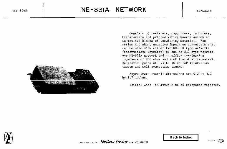
mm 1968 NE-83lA NETWORK STANDARD
Consists of resistors, capacitors, inductors, transformers and printed wiring boards assembled in moulded blocks of insulating material. Has series and shunt negative impedance converters that can be used with either two NE-830 type networks (intermediate repeater) or one NE-830 type network, one NE-832A network and an office terminating impedance of 900 ohms and 2 uF (terminal repeater), to provide gains of 0.5 to 10 db for interoffice tandem and toll connecting trunks.
Approximate overall dimensions are 9.2 by 3.2 by 1.7 inches.
Initial use: in J99253A NE-E6 telephone repeater.

APRIL 1970 NE-832 TYPE NETWORKS SEE RATINGS BELOW
NE-832A
NE-832A: Printed wiring board with four terminals.
Terminals 1 & 3 are electrically common and terminals 2 & 4 are electrically common.
Intended for use in 5992538 E6 telephone repeater when used for terminal application.
NE-832B: Consists of a block of insulating material
provided with a row of four terminal slots. The two inner slots are equipped with terminals connected by an 900 ohm resistor which is encapsulated in epoxy. The outer slots are unequipped. The four terminal slots are also used for mounting.
Code
NE-832A NE-832B
Rating
Standard 11
NE-8320

JULY 1969 NE - 834A NETWORK STANDARD
f I
Consists of apparatus such as capacitors and resistors mounted on a printed wiring board.
Approximate over-all dimensions are 3.25 inches by 2 inches by 0.64 inch deep. Arranged to mount by means of four 0.125 inch diameter holes on 1.625 inch by 2.875 inch centres. Provided with four .112-40 mounting screws and four l/2 inch long spacers.
Intended for use in the .J53009CV.

MAY 1977 NE-835A NETWORK STANDARD
,156’ -lr- -nn
Consists of forty diodes nmmted on a printed circuit board and connected to terminals that are arranged for mechanically wrapped connections.
Provided with rmmting screws.
Intended for use in isolating a signal franc an outgoing trunk mounted on a J67465C 'Bunk Termination Unit of the NIXA & 4M Toll Switching system.
PROPERTY OF Northern Telecom Limited

NOVEMBER 1969 NE- 836 TYPE NETWORKS SEE RATINGS BELOW
I-Q?@ a 2 3
Initial use: In NE-201 type repeaters as line building-out networks for type "DSA" lead-covered cable to provide fixed repeater spacing as specified in the table below.
NE-836A: Consists essentially of a terminal plate with terminals 1 and 2 strapped,
assembled in a plastic case.
NE-836B to M: Bridge "T" networks consisting of apparatus such as capacitors, inductors and
resistors assembled in a plastic case.
Code
NE-8368 NE-836B NE-836C NE-836D NE-836E
Equivalent Cable Length (Feet)
0 500
1000 1500 2000
Rating
Standard II ,I ,, II
WwN~~~RS’ L,.,,,,D ON NE-e.,SA 19 ARE FOR REFERENCE NE-836F 2500 ONLY NE-836G 3000 I,
NE-836H 3500 ,I
NE-8367 4000 ,I NE-836K 4500 8,
NE-836L 5000 II
NE-836M 5500 ,I

MAY 1972 NE-837 TYPE NETWORKS SEE RATINGS BELOW
NE-8378 (OTHERWISE SAME
AS NE-837A)
NE-837C (OTHERWISE SAME
AS NE-837.4)
Each consists of capacitors, inductors, transformers and printed wiring boards assembled in a metal case. Provided with NE-239C jacks for testing, screws for adjusting input capacitance and wire gauge and/or screws for adjusting loop resistance. Two 0.190 inch - 32 studs are provided for mounting on 2.25 inch centres. Four wire wrap terminals extend approximately 0.5 inch beyond the mounting surface.
NE-837A: Intended for use as a line building-out network for 19, 22,
and 24 gauge H88 loaded, high capacitance cable in class 4 or 5 offices and on the office end of a loaded loop.
NE-837B: Intended for use as a line build-out network where the
NE-837A network cannot be used because of insufficient build-out capacity.
NE-837C: Has a potentiometer for making return loss adjustments. Intended for use in conjunction with a 599253 E6 telephone
repeater using an NE-830C network. The NE-037C is connected to the 22, 24 or 26 gauge non-loaded cable at the end remote from the NE-f330C network to provide improved impedance and insertion loss.
Code Rating
NE-837A NE-837B NE-837C
Standard II II

NOVEMBER 1969 NE- 838 TYPE NETWORKS SEE RATINGS BELOW
I
Consists of a modulator, attenuating pads with and without adjustable resistors and a switch.
.I36 -32
.6 THRE*o
The component apparatus is mounted on printed wiring boards and enclosed in a metal case for shielding.
Closest recommended mounting centres are 1.875 inches by 3.625 inches.
NE-838A: Develops 424 kHz from a source of 516 kHz and 92 kHz
and adjusts the level of 92 kHz and 424 kHz to supply calibrating frequencies.
Initial use: 568774P L-carrier group and supergroup pilot-measuring circuits.
NE-838B: Same as NE-838A except develops 424 kHz from a
source of 516 kHz (75 ohms, unbalanced) and 92 kHz (40 ohms, unbalanced).
Initial use: 568774P L-carrier group and supergroup pilot-measuring circuits with 568857 type carrier supplies.
Code Rating
NE-838A NE-838B
Standard 11

OCTOBER 1969 NE-839A NETWORK STANDARD
Consists of component apparatus mounted on a printed wiring board and enclosed in a metal case.
The NE-839A network includes a resistance pad, a double balanced ring demodulator, and a low-pass filter.
It is designed to translate one of five groups in the frequency band 312 to 552 kHz by the use of a carrier to the 60 to 108 kHz band. The upper sideband is suppressed by the low-pass filter.
It is intended for use in the J68858M receiving group amplifier in the NE-L multiplex terminal.

NOVEMBER 1969 NE- 849 TYPE NETWORKS SEE RATINGS BELOW
I-"1 Each consists of resistors
in a metal case, except NE-849C
Provided with a 78-S6M-051 for adjusting loss.
and a transformer on a cast epoxy board and assembled which does not contain a transformer.
Amphenol socket to accommodate an NE-89 type resistor
Terminated in a NS-14524 L9 connector for plug-in mounting.
Tabs are provided on the an NE-602C tool.
front of the case so that the network may be removed by
!I I NE-849A: 7 Intended for use in lieu of a transmitting amplifier where no gain is required
and where the output impedance is 1200 ohms.
NE-849B: Intended for use in lieu of a receiving amplifier where no gain is required
and where the input impedance is 1200 ohms.
NE-849C: Intended for use in lieu of a transmitting or receiving amplifier where no gain
is required and where both input and output impedances are 600 ohms.
Code
NE-849A NE-849B NE-849C
Rating
Standard I, 11

NE - 85lA NETWORK STANDARD
Consists of apparatus such as capacitors and 'transformers mounted on a printed wiring board.
Contains a hybrid circuit for combining odd and even supergroup frequencies in the 60 to 3000 kHz range. Sending and receiving impedance is 75 ohms.
Arranged to mount by means of four 0.166 inch diameter holes on 4.600 by 2.800 inch centres.
Approximate overall dimensions are 3.250 inches wide by 5.000 inches long by 0.712 inches high.
Initial use: J68858F supergroup modulator and filter shelf assembly for NE-L type multiplex equipment.

APRIL 1977 NE-852A NETWORK
rut northom tmcom
Gmsists of apparatus such as a transistor, varistor, diode, capacitor and resistors, munted on a printed circuit board.
Terminated in five printed wiring t erminals in the form of spade type cord tips associated with five .125 inch wide munting slots on .300 inch centres across the 1.75 inch width.
Intended to supplement relay type gain disablers associated with E6 telephone repeaters on certain types of trunks. Where the network is used, reinsertion of the repeater gain is delayed l/4 second following each chain of dial pulses, thereby suppressing singing at audio frequencies.
Over-all dimens ions are 2.66 inches long by 1.75 inches wide by 0.75 inch deep.
Initial use: J99253F, 5992536 and J99253L.
PROPERTY 01 Northern Telecom Limited

OCTOBER 1976 NE-1400 TYP$$TWORKS a
Waveguide networks.
4.312
1
Each consists of one NE-4A junction, one NE-5A junction and two identical filters assembled together.
1.852 2.776
Provided with sixteen cap screws for assembly to associated apparatus.
i‘ 21.0 Intended for use, in conjunction with
- 3.750 .+ 6.000 - modified R.M.A. WR-229BD waveguide components, 1 as radio frequency channel branching networks
for receiving in the TD-2 and NTD-2 radio
northorn tolcrcum
PROPERTY OF Northern Telecom Limited

OCTOBER 1976 NE-1400 TYP$ f’J’J;TWORKS a
Mid-Frequency Code of=)
(a)NE-1400A 3730 (b)NE-1400AQlA 3730 (a)NE-1400B 3770 (b)NE-1400BQlA 3770 (a)NE-1400C 3810 (b)NE-1400CQlA 3810 (a)NE-1400D 3850 (b)NE-1400DQlA 3850 (a)NE-1400E 3890 (b)NE-1400EQlA 3890 (a)NE-1400F 3930 (b)NE-1400FQlA 3930 (a)NE-1400G 3970 (b)NE-1400GQlA 3970 (a)NE-1400H 4010 (b)NE-1400HQlA 4010
(a)NE-1400.J 4050 (b)NE-1400JQlA 4050 (a)NE-1400K 4090 (b)NE-1400KQlA 4090 (a)NE-1400L 4130 (b)NE-1400LQlA 4130 (a)NE-1400M 4170 (b)NE-1400MQlA 4170
<a) Has a light grey finish. (b) Has a metalic green finish.
Code
(a)NE-1400N (b)NE-1400NQlA (a)NE-1400P (b)NE-1400PQlA (a)NE-1400R (b)NE-1400RQlA (a)NE-1400s (b)NE-1400SQlA (a)NE-1hOOT (b)NE-1400TQlA (a)NE-1400U (b)NE-1400LJQlA (a)NE-1400W (b)NE-1400WQlA (a)NE-1400Y (b)NE-1400YQlA (a)NE-1400AA (b)NE-1400&!QlA (a)NE-1400AB (b)NE-1400ABQlA (a)NE-1400AC (b)NE-1400ACQlA (a)NE-1400AD (b)NE-1400ADQlA
SEE RATINGS BELOW
I
Mid-Frequency (MHZ) Rating
3710 Standard 3710 11 3750 ,I 3750 II 3790 1, 3790 11 3830 9, 3830 ,I 3870 11 3870 9, 3910 ,I 3910 11 3950 9, 3950 II 3990 11 3990 11 4030 II 4030 ,I 4070 11 4070 I9 4110 II 4110 ,I 4150 11 4150 II
nit nurthcm tclccom
PRO~EA~Y OF Northern Telecom Limited

/ OCTOBER 1976 NE-1401 TY;f=& t$ETWORKS
462
210
6000 -
Waveguide networks.
Each consists of one NE-4 one NE-5 type junction and two filters assembled together.
Provided with sixteen cap
type junction, NE-1300 type
screws for nssembly to associated apparatus.
Tntended for use in conjunction with modified R.M.A. WR-229BD waveguide components as radio frequency channel branching networks for transmitting in the TD-2 and NTD-2 radio svstems.
nit nutthem tQlQcom PROPtRTl OF Northern Telecom Limited

OCTOBER 1976 NE-1401 TYF$&TWORKS
Code Mid-Frequency
(MHz) Rating --
(a)NE-1401A 3730 (b)NE-140lAQlA 3730 (a)NE-1401B 3770 (b)NE-1401BQlA 3770 (a)NE-1401C 3810 (b)NE-1401CQlA 3810 (a)NE-1401D 3850 (b)NE-1401DQlA 3850 (a)NE-1401E 3890 (b)NE-1401EQlA 3890 (a)NE-14OlF 3930 (b)NE-1401FQlA 3930 (a)NE-1401G 3970 (b)NE-1401GQlA 3970 (a)NE-1401H 4010 (b)NE-1401HQlA 4010 (a)NE-1401J 4050 (b)NE-1401JQlA 4050 (a)NE-1401K 4090 (b)NE-14OlKQlA 4090 (a)NE-1401L 4130 (b)NE-1401LQlA 4130 (a)NE-1401M 4170 (b)NE-1401MQlA 4170
(a) Has a light grey finish. (b) Has a metalic green finish.
nwthcm tchconl
SEE RATINGS BELOW
Mid-Frequency Code (MEZ)
(a)NE-1401N 3710 (b)NE-1401NQlA 3710 (a)NE-1401P 3750 (b)NE-1401PQlA 3750 (a)NE-1401R 3790 (b)NE-140lRQlA 3790 (a)NE-1401s 3830 (b)NE-1401SQlA 3830 (a)NE-1401T 3870 (b)NE-14011'QlA 3870 (a)NE-1401U 3910 (b)NE-14nlUQlA 3910 (a)NE-14OlW 3950 (b)NE-1401WQlA 3950 (a)NE-14OlY 3090 (b)NE-1401YQlA 3990 (a)NE-1401,~ 4030 (b)NE-1401AAQlA 4030 (a)NE-140lAB 4070 (b)NE-140lABQlA 4070 (a)NE-1401AC 4110 (b)h‘E-1401ACQlA 4110 (a)NE-1401AD 4150 (h)"xIF-1 401 ADOlA 4150
Rating
Standard ,*
PROPERiY OF Northern Telecom Limited

FEBRUARY 1972 NE-1402 TYPE NETWORKS SEE RATINGS BELOW
I
Waveguide channel separation networks.
Each consists of two NE-2B junctions, two NE-1306 type filters, and one NE-502A terminations, assembled together.
Intended for use in conjunction with WR90 waveguide components in the TJ radio system.
Code Mid-Frequency
(MHZ) Rating
NE-1402A 10,715 NE-1402B 10,755 NE-1402D 10,835 NE-1402F 10,915 NE-1402G 10,955 NE-1402H 10,995 NE-1402N 11,245 NE-1402P 11,285 NE-1402R 11,325 NE-1402T 11,405 NE-1402U 11,445 NE-1402W 11,485 NE-1402Y 11,525 NE-1402AA 11,565 NE-1402AC 11,645 NE-1402AD 11,685

NE-1405A NETWORK
Dual polarization antenna feed network consisting of a NE-4A transducer and a polarizer assembly. Provides means for transferring all the power from two separate dominant mode rectangular waveguides into two orthogonal polarizations in a circular waveguide.
0
7
@
/
,..
*-- 2;--.
Arranged for connection between two pressurized WR90 size waveguides and one pressurized WC75 size waveguide.
Provided with gaskets, waveguide screws, nuts and lock-washers as shipped loose parts.
Intended for use in the TJ radio system.

NE-1407QA NETWORK STANDARD
Consists of a 1.790 inch square waveguide coupled to a 1.752 inch by 0.872 inch rectangular waveguide by means of a coupling plate having a series of special slots. The square and rectangular waveguides are dominant mode waveguides in the 4 GHz range. The coupling plate serves as a common wall between the two waveguides and is arranged to couple only one polarization in the square waveguide. Arm 1 and Arm 2 are each equipped with a flange which is arranged to connect to an NE-6QA, NE-7QA or NE-29BQA transducer or other waveguide apparatus having a square pressurized flange of the same size. Arm 3 is arranged to connect to pressurized wR229 waveguide apparatus.
Shipped with a protecting cover, gasket, and half the screws, nuts and washers needed for each external flange.
The network extracts one of the 4 GHz polarizations and transmits the other, for the 6 GHz and 11 GHz carrier bands.
and transmits both polarizations When two of these networks are connected in cascade and rotated 90' with
respect to each other, they extract both 4 GHz polarizations and transmit both polarizations for the 6 GHz and 11 GHz carrier bands. For this application, one ~30~076 waveguide is required but is not furnished and must be ordered separately.
Intended for use in the systems separation network for the 4 GHz, 6 GHz and 11 GHz carrier bands.

1409A NBTdORK STANDARD
Tote 1409A network is a special microwave coupler designed to connect to h'R-90 pressurized kmvewde. - __ -. __-.
The over-all dtiensions GY2.875 inches by 2.500 inches ba 5.844 inches long.
~%S??+O~A~i~etwork is i three port device designed to provide complete power transfer from the thru-port (A) to the side-port (B) and to permit water drainage thru a perforated cover connected to the thru-port (C). The return loss of ports (A) and LB) Is 3O-db minimum, and the insertion loss from port (A) to port (B) is 0.2-db maximurn over the frequency range 10.7 to 11.7 kllomegacycles per second.
It Is intended for use iri the ED-59741-30 as part of the TL radio system station equipment.
D3es not replace any apparatus.

DECEMBER 1971 NE-4002A NETWORK STANDARD
2.a64s*
1.469"
,064"
cz : ,152 "
Consists of capacitors and an inductor plotted in a metal case.
Terminal 1 is arranged to mount a commercial 2N43 tube type transistor.
Nominal resonating frequency between terminals 1 and 3 with 9 volts applied is 1000 hertz.
Approximate dc resistance between terminals 1 and 3 is 29 ohms.
Closest recommended mounting centres are 2.125 inches by 3.0 inches.
Intended for use in the J9407l.A & B milliwatt generators.

MARCH 1970
. . -
NE-4011 TYPE NETWORKS SEE RATINGS BELOW
I I
t--- “200 -I
‘200 1 t- .Ooo 1 Stabilized, temperature-compensated precision resistance-
capacitance networks, each having a 2.15% tolerance on the time-constant as shown in table below.
Each consists of a series connected capacitor and resistors potted in a plastic case.
Arranged to mount on printed wiring boards.
Suitable for use over an operating temperature range of -4O'C to +65'C at a maximum voltage of 100 vdc.
Closest recommended mounting centres are 1.719 inches by .937 inch.
,.032 OIA
I
,J I- -
1.250
T 320
l
Code
NE-401lA NE-4011B NE-4011C
Nominal Time-Constant
(uF Ohms]
265.2 212.16 169.73
Bating
Standard 11 II

NE-4013A NETWORK
Consists of twelve NS14338 capacitors, and twelve NS13490 L2 1500 ohm resistors assembled between two terminal boards. The boards are supported by a bracket which is used for mounting.
The capacitors are strapped together to form a common terminal.
Approximate overall dimensions are 4.50 inches long by 0.50 inch wide by 1.156 inches high, not including resistor and capacitor wire terminals which project 0.20 inch from top of board.
Intended for use in the data-phone, 401B receiver in JlD4OlB-Ll to prevent large voltage transients from developing across the associated relay winding.

JUNE 1972 NE-4014A NETWORK STANDARD
Consists of twelve NE-542A capacitors and twelve NS13490 L2 470 ohm resistors assembled between two terminal boards. The boards are supported by a bracket which is used for mounting.
The capacitors are strapped together in groups of four to form three common terminals.
Approximate overall dimensions are 4.50 inches long by 0.890 inch wide by 1.156 inches high not including resistor and capacitor wire terminals which project 0.20 inch from top of board.
Intended for use in the data-phone, 401B receiver in JlD401B-Ll to prevent large voltage transients from developing across the associated relay winding.

NOVEMBER 1970 NE-4015 TYPE NETWORKS SEE RATINGS BELOW
‘BLACK
FIG I
FIG. 2 (OTHERWISE
SAME AS FIG I)
NE-4015A: Consists of a diode and thermostats assembled in a
thermally stable glass flask, enclosed in a cover of insulating material and wired to three resistors and connected to terminals which are part of the mounting bracket. Equipped with six flexible leads approximately 8.00 inches long.
An operating temperature of 120°C within the flask is intended to be maintained by an external transistor circuit, not a part of the network, which is under the control of the thermostats. The starting power required is 8 watts at 48 volts dc. The power required to maintain the network at the operating temperature with an ambient range of O°C to 49OC is 1.5 watts.
Contains nonlinear elements arranged to compress voice signals when used with an NE-4020A network.
Initial use: NE-4020A network.
NE-4015B: Same as NE-4015A except contains
arranged to expand voice signals when network, contains 5 resistors and has leads.
Initial use: NE-4020B network.
nonlinear elements used with an NE-4020B 7 flexible terminal
Code Fig Rating
NE-4015A 1 Standard NE-4015B 2 II
.

APW 1977 NE-4017 TYPE NETWORKS
Each consists of a winding on a permalloy powder core and a capacitor potted in a hermetically sealed metal case.
t ,907" Y
FIG. I
nit northern tchcolll
With 5.5 wits applied between te nninals land 3with terminal 3 and case grounded, the n-1 parallel resonance frequency is shown in the table below.
May comf equipped with a capacitor externally connected across terminals 1 and 3. Termina 1 2 is a centre tap on
FIG 3
(OTHERWISE SAME AS FIG I! winding (l-3).
NE-4017AB:
Closest ret ormmded munting centres are 1.969 inches by 2.500 inches.
.3
@aI@ NE-4017A thru L,P,T,U & W:
The ncminal conductance at resonance is 44.3 micromhos. 1 2 I
I I With 1.1 volts applied between terminals 1 and 2 with ;erminal 2 and case grounded, the nominal parallel resonance
FIG.2 frequency is shown in the table below. (OTHERWISE SAME AS FIG. I1 May cane equipped with a capacitor externally connected
across terminals 1 and 2.
NE-4017N & s: The mximun conductances at resonance are 90.0 and 75.0
micromhos, respectively.
With 1 volt applied between terminals 1 and 3 with tetisl 3 and case grounded, the n aninal parallel resonant frequency is 17,160 Hz and the ncminal conductance is 20 tnicrtios; with terminal 1 connected to terminal 4, the naninal parallel resonant frequency is 14,040 Hz and the ncxninal conductance is 25
mircdnhos.
PHOPERTY OF Northern Telecom Limited T I, rJ.c.Fl. @

APRIL 1977 NE-4017 TYPE NETWORKS (Card?‘)
SEE RATINGS BELm
code
NE-4017A NEk4017B NE-4017c NE-4017D NE-4017E NE-4017F NE-4017G NE-4017H NE-4017J m-4017K NEh4017L NE-4017N NE-4017P NE-4017s NE-4017T NE-4017u NE-4017-v NE-4017AB
Fig. No.
Nominal Parallel Ftesonance Frequency
(Hertz)
697 770 852 941
1209 1336 1477 1633 2050 2150 2250 2600 1017 3699 600
1098 1950
19160 14040
PRO~~~~y OF Northern Telecom Limited

/ MARCH 1975 NE-4019 TYPE NETWORKS SEE RATINGS (Card 1) BELOW
Each consists of apparatus such as resistors, transformers, transistors, diodes, potentiometers, etc., wired to printed wiring obard and assembled in a metal frame. Terminated in two 502AQlA plugs.
Initial Use: NE-T1 carrier telephone system.
NE-40198: Designated XMTG CLK. Provides the source of
digital timing, channel synchronizing, and channel grouping pulses for controlling the 24 channel PCM bank type Dl. NE-4019B:
Designated XMTG CONV SIG. Provides for combining, framing, coding, and signaling pulses in the 24 channel PCM bank type Dl to form a composite unipolar signal. This signal is in turn converted to a bipolar signal for forwarding to the transmission line through the alarm unit. NE-4019C:
Designated XMTG ENC DR. Provides the memory devices for storing information during the transformation of pulse amplitude modulated signals into binary code form in the 24 channel PCM bank type Dl.
Code
NE-4019A NE-4019B NE-4019C
Rating
Standard II 9,

MARCH 1975 NE-4019 TYPE NETWORKS (Card 2)
SEE RATINGS BELOW
NE-4019D: Designated XMTG GTS. Provides for voice-band limiting and periodic sampling under the control of the
transmitting-counter networks of the voice signal to obtain a corresponding pulse amplitude modulated signals. NE-4019E:
Designated XMTG CTR. Provides sampling pulses for controlling the timing of six transmitting gates (one NE-4019D network) in the 24 channel PCM bank type Dl. A channel driving stage for a single group 12 channels and a channel one inhibiting stage are included with this unit.
NE-4019F: Designated XMTG CTR. Provides sampling pulses for controlling the timing of six transmitting gates (one
NE-4019D network) in the 24 channel PCM bank type Dl. NE-4019G:
Designated (RCVG FR). Provides detection of framing and logic information for controlling the receiver digit pulse generator (NE-4019H) in order that the receiver scanning of the 24 channel PCM bank type Dl will maintain synchronism with the transmitter. In the event of a system timing failure, this network also initiates an alarm signal.
NE-4019H: Designated DIG GEN. Provides a repeating series of digital pulses, accurately controlled by the clock
network (NE-4019A), for use in the various timing applications in the 24 channel PCM bank type Dl. NE-4019J:
Designated RCVG CTR. Provides sitching pulses for controlling the timing of six receiving gates (one NE-4019L network) for signal reconstruction in the 24 channel PCM bank type Dl. A channel driving stage for a single group of 12 channels and a channel one inhibiting stage are included with this unit.
Code Rating
NE-4019D NE-4019E NE-4019F NE-4019G NE-4019H NE-4019J
Standard Standard Standard Standard Standard Standard

MARCH 1975 NE-4019 TYPE NETWORKS
(Card 3)
SEE RATINGS BELOW
NE-4019K: Designated RCVG CTR. Provides switching pulses for controlling the timing of six receiving gates (one
NE-4019L network) for signal reconstruction in the 24 channel PCM bank type Dl. NE-4019L:
Designated RCVG GT. Provides for reconstructing the voice signals for the corresponding amplitudes of analog pulses (PAM signals) under the control of the receiving counter (NE-4019J & K) networks.
NE-4019M: Designated RCVG CONV SIG. Converts the incoming composite bipolar signal from the transmission line to
a unipolar signal, and extracts the signaling pulses required for use in the receiving channel of the 24 channel PCM bank type Dl.
NE-4019N: Designated CODE GEN & DET. Provides the equivalent of a test tone which is required for gain adjustment
of the receiving common equipment. Provided with three microswitches for alignment adjustments of Group 1. NE-4019P:
Designated TBL LOC. Permits measurement of pulse heights and pulse rates, and provides a means for connecting and measuring a PAM transmission circuit from compressor to expandor.
NE-4019R: Designated PAM DET. Converts PAM signals to sine waves by extracting the envelope of the PAM signals so
that they may be measured using COnVentiOnal transmission measuring instruments. Provided with a microswitch for
alignment adjustment.
Code Rating
NE-4019K NE-4019L NE-4019M NE-4019N
(a) NE-4019P (a) NE-4019R
Standard 9, 11
Mfr. Disc.; repl. by NE-4019AB Standard
11

NOVEhSER 1977 NE-4019 T’bkP,E,, NETWORKS SEE RATIt
( BELOW
NE-4019u: Designated 1KC PEJ FLT. Provides a means for measuring total harmonic distortion and noise resulting from a fundamental signal of 1000 Hz when applied at the I-wire input of a channel bank. It is also used when checking the system performance after alignment.
NE4019AA: Designated RCVG THRU CONN. Provides through connections for normal Dl channel bank operation in lieu of each test board network.
NE-4019AB : Designated CODE GEN & DET. Provides the equivalent of a test tone which is required for gain ad- justment of the receiving common equipment. Provided with four microswitches for alignment adjustment of Group 1 or Group 2 equipment.
NE-4019AQA: Designated KMTG CLK. When clocked either externally or from internal crystal clock; provides the source of digital timing, channel synchronizing and channel group pulses for controlling the 24 channel PCM bank type Dl.
NE-4019BD: Designated as XMTG GTS TOLL. Provides for voice band limiting to approach toll requirements and provides sampling under the control of the transmitting counter network of the voice signal to obtain a corresponding pulse amplitude modulated signal.
NE-4019BH: Designated DIGIT GENERAMR. Provides a repeating series of digital pulses accurately controlled by the network (NE-4019A) for use in various timing application in the 24 channel PCM bank type Dl.
CODE RATING
nit northern tQhCQm
(a)NE-4019U (a)NE-4019AA (a)NE-4019AB
NE-4019AQA NE-4019BD NE-4019BH
(a) Required for testing applications only.
PROPERTY OF Northern Telecom Limited ..I. ..=.I). CD

DECEMBER 1971 NE-4020 TYPE NETWORKS (Card 1)
?-- --- 8 926” -1
NE-4020A ALSO GENERAL DESIGN AND DIMENSIONS OF NE -4020 TYPE

DECEMBER 1971 NE-4020 TYPE NETWORKS (Card 2)
SEE RATINGS BELOW
Each consists of resistors, transformers, transistors, diodes, potentiometers, etc, wired to two printed wiring boards and assembled in a metal frame. Terminated in two NE-502A plugs.
Initial use: 598711, Dl channel bank equipment.
NE-4020A:
Designated XMTG COMP. Logarithmically compresses the channel voice samples to a range of voltages which are acceptable for injection into the encoder circuit.
NE-4020B:
Designated RCVG EXP. Logarithmically expands decoded voice samples to their original range of loudness, and amplifies the resulting signal to a level which is acceptable for injection into the receiving gate circuit.
NE-4020C:
Designated XMTG ENC NET. Converts each voice sample in a pulse amplitude modulated signal into a seven digit word, binary coded to represent the amplitude, fed in a unipolar pulse code modulated signal to the transmitting converter.
Provides logic information to reset memory devices in the encoder drive.
NE-4020D:
Designated RCVG DEC. Converts each seven digit word in a unipolar pulse code modulated signal from the receiving converter into a pulse of corresponding compressed voice sample amplitude in the pulse amplitude modulated signal delivered to the expandor. Synchronized timing is provided by the receiving digit pulse generator.
Code Rating
Q NE-4020A Standard NE-4020B tt
NE-4020C II
NE-4020D (1
mommY cx THE Non%ern Elk&k ccn.,~mu EMOTED

DECEMBER 1971 NE-4025A NETWORK STANDARD
Impedance compensating network consisting of capacitors, inductors, resistors, and transformers assembled in a metal case.
Intended for paralleling NE-593A to NE-593E filters.
Closest recommended mounting centres are 1.381 inches by 2.740 inches.
Intended for use in the 568858 NE-L type multiplex carrier telephone equipment.

DECEMBER 1969 NE-4027 TYPE NETWORKS SEE RATINGS BELOW
0 I
Each consists of apparatus such as capacitors, diodes, inductors and resistors mounted on a printed wiring board and assembled on a metal frame. Terminated in an NE-502AQlA plug at one end.
Over-all dimensions are 7.248 inches high by 1 inch wide by 7.271 inches long including the plug, but not including connectors.
Initial use: J98710F fault locating set (NE-T1 carrier).
NE-4027A: Provides the circuitry for the unipolar flip-flop, clock and power supply required for the associated digit generator.
The end opposite the NE-502AQlA plug is equipped with a NS-13998 L16 capacitor for calibrating.
NE-4027B & C: The end opposite the NE-502AQlA plug is equipped with two NS-14523 connectors for testing.
NE-4027B: Provides the circuitry for the associated digit oscillators.
NE-4027C: Provides the circuitry for the audio flip-flop, gating and blocking oscillator required for the associated digit generator.
Code
NE-4027A NE-4027B NE-4027C
Rating
Standard ,I 11

JUNE 1972 NE-4030 TYPE NETWORKS SEE RATINGS BELOW
Each consists of apparatus such as capacitors, resistors, and transformers potted in a metal case.
Terminal 1 is identified by means of a black dot. Closest recommended mounting centres are 1.219 inches by 1.625 inches. Initial use: 568858 L type multiplex carrier telephone equipment.
NE-4030A: Unbalanced network containing a 75 + 75 to 75 + 75 ohm hybrid transformer.
Intended to operate over the frequency range of 50 to 3000 kHz. NE-4030B:
Balanced network containing a 135 + 135 to 135 + 135 ohm hybrid transformer. Intended to operate over the frequency range of 60 to 108 kHz.
NE-4030C: Unbalanced network containing a 4000 to 34 + 34 ohm transformer with a 2000
ohm resistor in series with the 4000 ohm winding. Intended to operate between 6000 ohm input and 135 ohm output resistances. There are no electrical connections to terminals 7 & 8.
NE-4030D, E, F, & H: Each contains an unbalanced pad intended to operate between 75 ohm
resistances and have losses of approximately 5.0 dB, 18.1 dB, 12.0 dB, and 15.0 dB, respectively. There are no electrical connections to terminals 5, 6, 7, & 8.
NE-4030G: Unbalanced network intended to operate between 135 ohm resistances. There
are no electrical connections to terminals 2, 3, 6, & 7.
Code Rating Code Rating
NE-4030A NE-4030B NE-4030C NE-4030D
Standard 11 II II
NE-4030E NE-4030F NE-4030G NE-4030H
Standard 71 11 II

DECEMBER 1971 NE-4031 TYPE NETWORKS SEE RATINGS BELOW
Unbalanced networks intended to operate between sending and receiving resistances of 75 ohms.
Each consists of capacitors and inductors mounted on a printed wiring board and assembled in a metal case.
Terminated in a Sealectro Corp No H6112 coaxial connector. Closest recommended mounting centres are 2.750 inches by 5.250 inches. Initial use: 568858.
NE-4031A: Intended to be connected across the paralleling terminals of the odd-numbered (1, 3,
5, 7, 9) super-group filters NE-612A, NE-612B, NE-613C, NE-613E and NE-613G. NE-4031B:
Intended to be connected across the paralleling terminals of the even-numbered (2, 4, 6, 8, 10) super-group filters NE-613A, NE-613B, NE-613D, NE-613F and NE-613H.
NE-4031C: Intended to be connected across the paralleling terminals of the odd-numbered (13, 15,
17, D25, D27) super-group filters NE-612B, NE-613C, NE-613E, NE-613J and NE-613L. NE-4031D:
Intended to be connected across the paralleling terminals of the even-numbered (14, 16, 18, D26, D28) super-group filters NE-613B, NE-613D, NE-613F, NE-613K and NE-613M.
NE-4031E: Intended to be connected across the paralleling terminals of the even-numbered (12,
14, 16, 18, D26, D28) super-group filters NE-613A, NE-613B, NE-613D, NE-613F, NE-613K and NE-613M.
Code
NE-4031A NE-4031B NE-4031C
Rating
Standard 11 11
Code
NE-4031D NE-4031E
Rating
Standard 11

DECEMBER 1971 NE-4032 TYPE NETWORKS SEE RATINGS BELOW
Each consists of a capacitor and inductor potted in a metal case.
Closest recommended mounting centres are 1.093 inches by 1.~5o~ir~V?res; .
Initial use: J99272F
Nominal Conductance Effective Nominal Type Resonance at Resistance At
Inductance of Frequency Resonance Resonance Code (uW Resonance (Hertz) (Micromhos) (Ohms)
NE-4032A 78.23(a) Parallel 4218 6.0 max NE-4032B 230. (b) Series 3030 125 max
(a) Between terminals 1 and 3. There are no electrical connections to terminals 2 and 4.
(b) Between terminals 2 and 3. Capacitor is between terminals 1 and 3. There is no electrical connections to terminal 4.
Code
NE-4032A NE-4032B
Rating
Standard 11

DECEMBER 1971 NF4034A NETWORK STANDARD
Consists of fourteen network units, each unit consisting of a .SuF capacitor and a 470 ohm resistor connected in series, moulded in a cast resin block. The units are divided into three groups, two groups each containing five network units and one group containing four network units. In each group, the capacitor terminals are connected together and terminated at terminal leads 15, 16 and 17. The resistors are terminated at terminal leads 1 to 14 inclusive.
Closest recommended mounting centres are 5.4 by 1.6 inches.
Initial use: JlD401F data set to prevent large voltage transients from developing across the contacts of associated relays.

DECEMBER 1971 NE-4036 TYPE NETWORKS SEE RATINGS BELOW
Each consists of an inductor, a transformer and resistors assembled in a metal case.
Terminals are arranged for mechanically wrapped connections.
Intended to operate over the voice frequency range.
Each has a turns ratio of 1 to 1 between terminals 5 & 6 to 7 & a.
040” DIAe,, Closest recommended mounting centres are 2.0 inches by 2.25
inches.
Initial use: NE-1 electronic switching system.
NE-4036A:
Has an impedance ratio of 600 to 900 ohms between terminals 1&2to3&4.
NE-4036B:
Has an impedance ratio of 900 to 900 ohms between terminals 1&2to3&4.
Approximate dc Resistance (Ohms) Between Terminals
Code l&2 3&4 58x6 7&S Rating
NE-4036A 14 18 2 2 Standard NE-4036B 21 21 2 2 (9

4037A 8 B NETWORKS SEE RATINGS JUNE 1965 BELOW
Each consists of four network units, each unit consisting of varistors and resistors mounted in plastic cavity blocks between two printed wiring boards, assembled in a metal can.
Terminated at one end in a connector for use with a 421A plug. The other end is arranged to connect to a 201A or B repeater.
Intended to provide high-voltage protection for cable pairs associated with the 201A and B repeaters.
40378; Intended for use with the 201A repeater.
4037B: Intended for use with the 201B repeater.
Code Rating
40378 Standard 4037B 18
P R o P E R T Y Norfbern Efecfric Compuny L I M I T E D

DECEMBER 1971 NE-4042 TYPE NETWORKS SEE RATINGS BELOW
I I
Each consists of resistors, capacitors and two NE-1595A inductors assembled in a metal case.
Terminals are arranged for mechanically wrapped connections.
Intended to operate over the voice frequency range.
Closest recommended mounting centres are 1.250 inches by 1.750 inches.
NE-4042A:
Has a turns ratio of 1 to 1 between windings (l-5) to (Z-6) and (3-7) to (4-8).
The approximate dc resistance between terminals 1 & 5, 2 & 6, 3 & 7 and 4 & 8 is 2.4 ohms.
Initial use: Coin zone dialli-ng circuits and four-port conference circuits of NE-1 electronic switching system per SD-lA185- 01 and SD-lA189-01 respectively.
NE-4042B:
Has a turns ratio of 1 to 1 between terminals 1 & 2 to 6 & 7.
The approximate dc resistance of windings (1-Z) and (6-7) is 12 ohms.
Initial use: Multifrequency environment test circuit of NE-l electronic switching system per SD-lA150-01.
NE-4042A NE-4042B
Standard 8,
Code Rating

SEPTEMBER 1973 NE-4043B NETWORK ’ STANDARD
Consists of two transformers assembled in a metal can. One of the transformers is arranged to limit lightning surge currents.
Intended to operate over the voice frequency range.
The turns ratio between windings (l-5),(2-6),(3-4), and (7-9) is 1 to 1 to 4 to 4.
Terminal 8 is a centre tap of winding (7-9).
Inductance of windings is 0.150 henry maximum and 200 Hz applied to winding
Maximum dc resistance
(l-5)(6-2) with 1.0 volt and 200 Hz applied 0.080 henry minimum. With 4.0 volts and
( 7-9) the minimum inductance is 80 henrys.
0 f windings (3-4) and (7-9) at 20°C is 3.2 ohms and 675 ohms, respectively.
Terminal one arranged for mechanically wrapped connections.
Closest recommended mounting centres are 2.00 inches by 2.25 inches.
Initial use: NE-1 ESS Conference Circuits.

FEBRUARY 1972 NE-4044 TYPE NETWORKS SEE RATINGS BELOW
E W
NE-4044A
“4 OL
4 -3
6:_ 2
e-WV-3 E W
NE -4044C
Each consists of apparatus such as an inductor, a varistor, a resistor and capacitors assembled in a metal case having a terminal plate of insulating material.
Provides input and output capacitors, an isolation inductor and a gain control resistor which are required for the NE-151E amplifier when the amplifier is used to amplify transmitter output. Also provides receiver click reduction.
NE-4044A:
Intended for use in the MF646 telephone consoles.
NE-4044C:
Intended for use in the NE-3C2QA and NE-4B2QA telephone consoles.
Code
NE-4044A NE-4044C
Rating
Standard II

MARCH 1975 NE-4053 TYPE NETWORKS SEE RATINGS BELOW
Each consists of an inductor on a square ferrite core, a capacitor and a resistor potted in a hermetically sealed metal case.
With a current as listed below flowing between terminals 1 and 3, with terminal 3 and case grounded, the nominal series resonance frequency and the nominal resistance at resonance is shown in the table below.
May come equipped with a capacitor externally connected across terminals A and B.
Closest recommended mounting centres are 2.86 inches by 1.808 inches.
Nominal Series Nominal Resonance Resistance
Current Freq at Resonance Code (nA) (Hz) (Ohms) Rating
NE-4053A 5.8 693.2 290 Standard NE-4053B 5.8 765.7 290 II
NE-4053C 5.8 847.4 290 II
NE-4053D 5.8 935.9 290 !,
NE-4053E 5.8 1202.3 290 ,I
NE-4053F 5.8 1328.7 290 !,
NE-4053C 5.8 1468.8 290 ,1
NE-4053H 5.8 1624.0 290 It

NOVEMBER 1975 NE-4066 TYPE NETWORKS (Card 1)
SEE RATINGS BELOW
I 00
7.000.
7.500’
0 I-L FIG. I
FIG. 2
FIG. S
FIG. 4
FIG. 5
FIG. 6
FIG. 7
TOP VIEWS (OTHERWISE SAME AS FIG. II
Two-terminal plug-in-type impedance networks. Each consists of apparatus such as resistors, inductors and capacitors mounted on printed circuit boards and contained in a metal case.
NE-4066A: Intended to balance the impedance of telephone circuits using No. 19, 22 and 24 AWG, H-88 loaded cables.
NE-4066B: Intended to balance the impedance of telephone circuits using No. 26 AWG, H-88 loaded lines.
NE-4066C: Provides selection of building out capacitance values from 0.001 UF to 1.0 UF in steps of 0.001 LJF by screw adjustment and/or comprise networks of 600 ohms plus 2 UF or 900 ohms plus 2 UF also by screw adjustment.
NE-4066D: Intended to balance the impedance of telephone circuits using No. 19 AWG toll, H-88 and H-50 loaded cables.
NE-4066E: Intended to balance the impedance of telephone circuits using No. 19 AWG toll, H-44 loaded cables.
Code Figure Rating
NE-4066A 1 NE-4066B 2 NE-4066C 3 NE-4066D 4 NE-4066E 5

NOVEMBER 1975 NE-4066 TV=!=*) NETWORKS SEE RATINGS BELOW
NE-4066F: Intended to balance the impedance of telephone circuits using No. 24 AWG, non-loaded 'cable.
NE-4066G: Provides on impedance balance at Z/4 wire junction of the telephone circuit using non-loaded No. 22, 24 and 26 AWG cable. Must be terminated with an impedance network simulating the impedance which terminates the ac- tual wire circuit being balanced.
NE-4066H: Terminates the NE-4066G network to provide the precision impedance balance of No. 22, 24 and 26 AWG non-loaded cable. Simulates the impedance of the 500 type telephone set and is adjustable for transmitter currents of 20, 42, 50 and 80 mA.
Code Figure Rating
NE-4066F 6 Standard NE-4066G 7 11
NE-4066H 2 ,I
6

DECEMBER 1971 NE-4084A NETWORK STANDARD
Consists of inductors, capacitors, and resistors mounted on two printed wiring boards and assembled in a metal case.
Contains two separate sections. One section contains an unbalanced band-pass filter, which is delay and loss equalized. It is intended to operate between sending and receiving resistances of 2000 ohms and pass frequencies from 650 to 3250 hertz. Terminals 1 and 2 are the input and 2 and 3 are the output terminals.
The other section is an unbalanced delay line, which is intended to operate between a zero sending resistance and a receiving resistance of 4000 ohms at each output. Operates over the frequency range of 650 to 3250 hertz and provides two output signals which have a 90° phase difference. Terminals 4 and 6 are the input, and 6 and 5 and 6 and 7 are the output terminals.
Initial use: JlG-OOOB.G four-phase digital data receiver of the Al digital data signalling system.

FEBRUARY 1972 NE-4086 TYPE NETWORKS
FIG 2 FIG 3 FIG 4 (OTHERWISE SAME (OTHERWISE SAME (OTHERWISE SAME
ASFIG I) AS FIG II AS FIG I) .138’-32 THREAOx
0.29”
7 2.71”
- FIG I

FEBRUARY 1972 NE-4086 TYPE NETWORKS SEE RATINGS BELOW
7)
Each consists of apparatus such as capacitors, inductors, and resistors potted in a hermetically sealed metal case.
Closest recommended mounting centres are 1.563 inches by 1.563 inches.
Initial use: Data units lA1, lB1, and 2Al.
Type of Nominal Nominal Number Tuned Between Frequency Impedance of
Code Figure Circuit Terminals (Hertz) (ohms) Terminals Rating -
NE-4086A 1 Parallel l&3 387 6650 4 Standard
l&3 387 3000 NE-4086B 2 Parallel l&2 387 100 1 5 11
4&5 387 100
NE-4086C 3 387 21,000 5 11 387 50
NE-4086D 3 Parallel 1 & 2(a) 3 & 4(a)
395 397
29,900 29,900 I
Cl& 3 387 3000)
NE-4086E 4 Parallel
I
l&2 4&5 6&8
387 100 387 100 387 6650 1
5
9
(a) With strap between terminals 1 & A removed.

MARCH 1975 NE-4087A NETWORK STANDARD
Consists of a head terminal assembly, 2-470 ohms and 2-100 Kilohms .5 watt Thick Film Resistors and two- LMF capacitor unit assemblies encapsulated in a metal can.
Impedance limit at 15KHz is 446 ohms minimum to 494 ohms maximum. DC resistance between terminals A-C or B-D is 85 Kilohms minimum to 115 Kilohms maximum at 25OC. Maximum operating temperature is 65'C.
.164-32 TH Closest recommended mounting centers are 0.875 inch by 1.500 inches.
460 / Initial IJse: Centrex Telephone system.

APRIL 1977 NE-4097A NETWORK SW
r 3 500”‘- t
1 L ;‘I
Pn inductance adjusmzntnetmrk.
Consists of ten inductors mnmted on a printed circuit board, one NE-597B key, one NS-14721 L14 switch, andoneNE-2KWkeyunitmuntedona in- sulated panel and enclosed in a metal can.
Equipped with two NE-893 cords, tw feet in length, terminated in a NE-354A plug.
Provides adjustable inductance in steps of 0.05 millihenry from 0 to 1.55 millihenry with the key operated in the NE-830C positian, and in steps of 10.0 millihenry frcxn 0 to 310 millihenry with the key operated in the NE-83OE position.
Initial use: Adjusting NE-830C and E Netmrks.
PROPERTY OF Northern Telecom Limited

( MARCH 1975 NE-4142QA NETWORK STANDARD
Consists of an NE-146A Repeating Coil, three resistors mounted on a epoxy glass laminated board,one toggle switch, five connectors and a plug wired and housed in a metal box.
The network is able to perform bridge measurements and terminated measurements on a 135 ohms circuit using a high inpedancr meter with a 600 ohm calibrated scale over the frequencv range of 4KHz to 128KHz.
Intended for use with .I68857 Ml Primary Frequency Supply (LxX2)

SEPTEMBER 1967 QNBIA NETWORK STANDARD
Consists essentially of capacitors, transformers and an inductor mounted on two hinged printed wiring boards and assembled in a cast metal frame.
Overall dimensions are approximately 2.00 inches wide by 4.70 inches high by 9.78 inches long.
Contains two separate identical circuits of three unbalanced band-pass filters in parallel connected to a QTKZA type transformer, with a common unbalanced output. Each filter is intended to operate between a sending impedance of 2000 ohms and a receiving impedance of 600 ohms. The three filters are arranged to pass a band of frequencies between, 12 kHz and 16 kHz, 16 kHz and 20 kHz, and 20 kHz and 24 kHz.
Initial use: MA-1 radio multiplex system.

JANUARY 1965 QNB2AI 8, 2A2 NETWORKS SEE RATINGS
BELOW
fo I I 0
0 -
COMPONENT SIDE
I 7.30
Each consists essentially of capacitors. resistors transistors. diodes, varistors, inductors and trans.- farmers mounLed on a printed wiring board.
Each is a two stage, transformer coupled, flat gain amplifier. Gain of the amplifier is 25db over the frequency range of 36 to 268KC Approximately 23DB of negative feed-back is used Lo obtain low distortion accuracy of gain and prescribed termination impedances.
Varistors :ire used for lightning protection.
Code
QNBZAl QNB2A2
Input Output Impedance Impedance
(Ohms) (Ohs)
100 100 135 135
Rating
Standard 1,

SEPTEMBER 1976 QNB3A TYPE NETWORKS SEE RATINGS BELOW
QNB3A4
(ALSO GENERAL DESIGN OF QNB3A TYPE)
nit northum t&corn
Each consists of a transformer, capacitors, resistors, and varistors assembled on a printed wiring board.
Height of network is approximately 1.25 inches. Intended to provide the transmission circuit elements including
the side tone balancing network, for an anti-sidetone telephone set. Also provides transmission equalization for varying loop lengths. Includes a ringing capacitor and a dial radio interference suppression filter.
QNB3A3: Initial use: NE-1630 type telephone set.
QNB3A4: Initial use: NE-624AlOQA and NE-1623A3QA telephone sets.
QNB3A5: Intial use: QCNlOOA type telephone console.
QNB3A6: Initial use: QSK420A, 421A, 422A & 423A (Candlestick) telephone
sets.
Code Rating
QNB3Al Standard QNB3A2 I,
QNB3A3 11
(a) QNB3A4 11
(b) QNB3A5 II
QNB3A6 $8
(a) Has extra terminals at designations B, GN, Ll, and G for greater wiring capacity.
(b) Has extra terminals at designations B, GN, F, Ll and G for greater wiring capacity.
Northern Telecom Limited
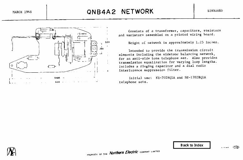
MARCH 1968 QNB4A2 NETWORK I STANIIARB
Consists of a transformer, capacitors, resistors and varistors assembled on a printed wiring board.
Height of network is approximately 1.25 inches.
Intended to provide the transmission circuit elements including the sidetone balancing network, for an anti-side tone telephone set. Also provides transmission equalization for varying loop lengths. Includes a ringing capacitor and a dial radio interference suppression filter.
Initial use: NE-702BQlA and NE-1702BQlA telephone sets.

MAY 1967 QNBSA TYPE NETWORKS SEE RATINGS BELOW
1
iY.zl ,312
i 1.438 1
Each consists of a capacitor and an inductor potted in a bakelite case.
Initial use: forms part of 1 kHz filter on the NE-7A carrier frequency noise measuring set.
Code
QNB5Al QNB5A2
Rating
Standard 11

FEBRUARY 1971 QNB7 TYPE NETWORKS (Card 1)
1
I Each consists of component apparatus mounted on a
1
printed wiring board and enclosed in a metal case.
Unbalanced networks intended to operate between sending and receiving impedances of 75 ohms.
Initial use: LC-1 1200 channel wire entrance link.

FEBRUARY 1971 QNB7 TYPE NETWORKS (Card 2)
SEE RATINGS BELOW
I I
QNB7A, B 6 C: Intended for use as de-emphasis networks over the frequency range specified in the table.
A switch provides switching from network to a resistive pad of 5.60 dB.
QNB7D, E, F, K, L & M: Each contains two circuits designed as stand-by units for the networks indicated in the table.
QNB7G, H & J: Intended for use as pre-emphasis networks over the frequency range specified in the table.
A switch provides switching from network to a resistive pad of 8.5 dB.
Code Fig Channel Capacity
Frequency &Hz)
Insertion Loss (dB) Rating
QNBlA 1 600
QNB7B 1 960
50 0.1 1000 5.6 3000 11.3
10 1.0 2270 5.6
10000 12.6
Standard
II
QNB7C 1
QNB7D 2
1300
1200 or 600
12.25 0.1 2780.00 5.6 1,
12250.00 12.6
Same as QNB7C II
Same as QNB7A
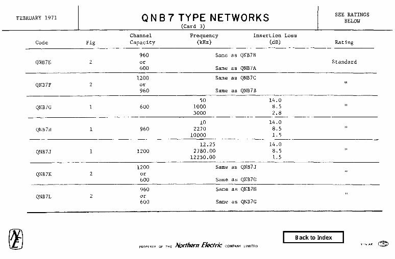
FEBRUARY 1971
Code
QNB7E
QNB7F
QNB7 TYPE NETWORKS SEE RATINGS BELOW
(Card 3)
Channel Frequency Insertion Loss Fig Capacity &Hz) (.dB) Rating
960 Same as QNB7B 2 or Standard
600 Same as QNB7A
1200 Same as QNB7C 2 II or
960 Same as ONB7B
QNB7G 1
QNB7H 1
QNB7.J 1
QNB7K 2
600
960
1200
1200
ZO
50 14.0 1000 8.5 II 3000 2.8
10 14.0 2270 8.5 9,
10000 1.5
12.25 14.0 2780.00 8.5 II
12250.00 1.5
Same as QNB7.1 11
Same as QNB7G
QNB7L 960 Same as QNB7H
2 II or 600 Same as QNB7G

FEBRUARY 1971 QNB7 TYPE NETWORKS (Card 4)
SEE RATINGS BELOW
Code Fig Channel Capacity
Frequency (kHz)
Insertion Loss (dB) Rating
QNB7M 1200 Same as QNB7J
2 ii0
Standard Same as QNB7H

NOVEMBER 1967 QNB8A TYPE NETWORKS (Card 1)
SEE RATINGS BELOW
QNBBAl: Consists essentially of inductors, capacitors and resistors assembled on a printed circuit board and
mounted on a metal casting.
Over-all dimensions are 9.68 inches long by 4.875 inches high by 1.0 inch wide.
De-emphasis network intended to reduce the amplitude of the high frequencies after their detection to restore the frequency to its original relative level over the frequency range of 60 to 1052 kHz.
Initial use: MA type multiplex system.
QNB8A2: Consists essentially of inductors, capacitors, resistors and transformers assembled on a printed
circuit board.
Pre-emphasis network intended to maintain a constant level of signal across the frequency range of 60 to 1052 kHz.
QNB8A3: Consists of one QEB3Al equalizer and one QFB32Al filter assembled on a printed circuit board and
mounted on a metal casting.
Overall dimensions are 9.78 inches long by 4.70 inches high by 2 inches wide.
Code Rating
QNB8Al QNK8A2 ONB8A3
Standard ,, ,I

NOVEMBER 1967 QNB8A Tk’~Pl&NETWORK SEE RATINGS BELOW
QNB8A4: Consists of one QFB32A2 and one QFB32A3 filter assembled on a printed circuit board and mounted
on a metal casting.
Over-all dimensions are 9.78 inches long by 4.70 inches high by 2 inches wide. J
QNB8A5: Consists of one QFB32A7 and one QE'B32A8 filter assembled on a printed circuit board and mounted
on a metal casting.
Over-all dimensions are 9.78 inches long by 4.70 inches high by 2 inches wide.
Code
QNB8A4 QNB8A5
Rating
Standard I,

NOVEMBER 1969 QNBSA TYPE NETWORKS
QNB9A2, 3 & 5: Each consists of apparatus mounted on two printed wiring boards and assembled in a metal frame. Contains fixed and variable elements which simulate electrical characteristics of 16 PSVL cable of
the lengths indicated in table. Intended to operate unbalanced between 75 ohms impedances. Overall dimensions are approximately 9.78 inches long by 4.875 inches high by 1.00 inch wide.
QNB9A4: Consists of apparatus mounted on a printed wiring board and assembled in a metal frame. Provides a balanced output impedance which matches that of the 16 PSVL cable over the frequency range of
8 kHz to 288 kHz. Input to unit presents a balanced or unbalanced 75 ohm input impedance or a balanced 86.6 ohm input impedance, to equipment connected to it. Also provides secondary lighting protection from lighting surges on the line.
Initial use: On wire line entrance links of MA-1 radio multiplex system.
Cable Length Simulated Code (Miles) Rating
QNB9A2 0.5 + 0.6 Standard QNB9A3 1.5 ? 0.6 0
QNB9A4 9,
QNB9A5 0 + 0.6 II

NOVEMBER 1967 QNBII TYPE NETWORKS SEE.RATINGS BELOW
Each consists of inductors, capacitors and resistors potted in a plastic case.
QNBllA: Used on NE-115H network.
QNBllB: Used on NE-115P network.
QNBllC: Used on NE-115R network.
Code
QNBllA QNBllB QNBllC
Rating
Standard 9, II

MARCH 1968 I QNB13A NETWORK I STANDARD
I
Consists essentially of inductors, capacitors and resistors assembled on two printed circuit boards and mounted in a metal frame.
Contains three separate band-pass filters which are intended to operate between sending and receiving impedances of 600 ohms.
Overall dimensions are approximately 2.00 inches wide by 4.70 inches high by 9.78 inches long.
Initial use: CA-2 order wire and alarm system.
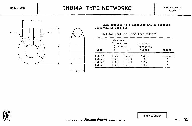
MARCH 1968 QNBI4A TYPE NETWORKS I SEE RATINGS BELOW
Each consists of a capacitor and an connected in parallel.
6
i
Initial use: in QFB6A type filters
inductor
Maximum Dimensions Resonant
(Inches) Frequency Code A B (Hertz) Rating
QNB14A 1.20 1.544 4400 QNB14B 1.20 1.653 3825 QNB14C 1.20 1.653 3854 QNB14D 1.20 1.731 3689
Standard 11 11 II

FEBRUARY 1970 QNBIGA NETWORK STANDARD
Consists of resistors assembled in a metal frame.
Terminated in two NE-470C jacks for coaxial connections.
Zero dB loss network intended to operate unbalanced between 75 ohms impedances.
Intended to complete transmission path when F55122 filter is not required in J68858CB signal connector.

DECEMBER 1969 QNBI7A NETWORK STANDARD
I I
Consists of an inductian coil, capacitors, varistors , and resistors assembled on a printed wiring board.
Height of network is approximately 1.250 inches.
Intended to provide the transmission circuit elements including the sidetone balancing network, for an anti-side tone telephone set. Also provides transmission equalization for varying loop lengths. Includes a ringing capacitor and a dial radio interference suppression filter.
Designed for use as an universal network in that all
i classes of ringing and number identification, including
5 685 - NE-lA, NE-lA1 key telephone systems and NE-3A speakerphone, 6 00 J II can be wired on the network.
Has provision for a modification which will suppress radio broadcast interference in telephone sets which may interfere with telephone conversations in certain locations.
Initial use: NE-702BQlA and NE-1702BQlA telephone sets.

QN618 TV)5 $ETWORKS SEE RATINGS
APRIL 1978 BELOW
r 2.00”
5.08 mm
L
0
0
aI--
QNBIBA SIMILAR TO QNBIB TYPE NETWORKS
RI
RVI
-N--
PRDPLRT” OF Northern Telecom Limited
RV2
I ?I
d R3 c4

APRIL 1978 QN818 TYPE NETWORKS SEE RATINGS
(Card 3) BELOW
Each consists of a QMM TYPE module, QVBlC & D varistors and resistors mounted on a printed wiring board. Electrically equivalent to the NE-425QEl network. Overall dimensions are approximately 3 inches long, 2 inches wide and 1 inch high.
QNB18A:
QNB18B:
QNBlBC:
QNB18D:
QNB18E:
Intended for use in the QSKlOOA type telephone sets.
Same as QNB18A except that it has two additional terminals required for mounting in antique type telephone housings. Intended for use with QSKlO type telephone sets.
Similar to QNB18B except has additional terminating points on the printed circuit board as required for use in the QSKZOO type telephone sets.
Similar to QNB18A, but with a QMM8A module and less a 22 ohm resistor. Intended for use in QSKlOOE for offshore locations.
Similar to QNBlX, instead of a QMMlA module it uses a QM?Jl7A and a QMM18A module.
Intended for use in the NE1 QSKZOO and QSK2200 type telephone sets.
CODE RATING
QNBl8A STANDARD QNB18B ,,
QNBlSC l,
QNB18D 1,
QNBl8E II
PROPERTY or Northern Telecom Limited

APRIL 1970 QNBISA NETWORK STANDARD
Unbalanced network intended to operate between sending and receiving impedances of 75 ohms.
Consists of a transformer assembled in a metal case.
Intended to operate over the frequency range of 60 kilohertz to 1.3 megahertz.
Initial use: LC-2 wire line entrance link.
(a) Terminal numbers are for reference only.

/ MARCH 1975 QNBZO TYPE NETWORKS SEE MTINGS BELOW
__ 3.130--A
These networks are channel filter units mounted on printed circuit boards. 'They are hermetically sealed in a can and terminated in a twelve pin connector.
-7
4940 I
Each channel has four filters, Low Pass Receive, Low Pass Transmit, Rand Pass Receive and Band Pass Transmit. The pass band for hoth the low pass receive and the low Pass transmit, for each channel is .8 KHz to 3.4 KHz. The pass band for the receiver and transmitter band Pass is indicated in table.
Code Pass Band Ratings __-
QNBZOA 12.3 KHZ to 15.8 KHz Standard ONBZOB 16.3 KHz to 19.8 KHz Standard QNB20C 20.3 KHz to 23.8 KHz Standard
Initial Use: MA-5 Channel Equipment.

MARCH 1975 QNBZI TYPE NETWORKS SEE RATINGS BELOW
---3.130 - Passive filters consisting of 44 capacitors and 16
inductors mounted on a printed circuit board and housed in a hermetically sealed can.
Between the two networks they accommodate 12 voice frequencv channels in the frequencv band 60 KHz to 108 KHz. Each network contains two filters in parallel with pass bands as indicated in table.
Code rass Band Rating ___-.
QNBZlA 60 Kllz to 72 Kllz Standard 84 KIlz to 96 KHz
0NBZlB 72 Kllz to 84 KHz 96 KHz to 108 KHz
Standard
Initial Use: YA-5,1 Frequency Division Multiplex.

JUNE 1971 QNB22A NETWORK STANDARD
Consists of a QMMlA moule, resistors, varistors, and an induction coil mounted on a printed wiring board. Electrically equivalent to the QNBl8A network.
Overall dimensions are 3.05 inches long by 2.81 inches wide by 1.125 inches high.
Special Sales Conditions apply.

MAY 1977 QNB24A NETWORK SW
Cmsists of 12 NE-NOA Varistors 12-QI1(44AL3 Transformrs, 12- QIP85A46 and 12-QHP85A47 Inductors, 2k~4446 Diodes and 96 capacitors mmted onaprinted circuit board.
Flat Loss at 1000 Hz is 0.6 db + .1 db.
Overall dimensions are 13.00 inches long by 3.45 inches wide by the height of the apparatus nwunted on the board.
Intended for use in the DE-2 PCM Channel Bank.
PROPERT” OF Northern Telecom Limited

QNB25A NETWORK
Consists of lo-capacitors, 6-inductors, lo-resistors and a trans- former munted on a printed circuit board.
Insertion loss 7.0 k .2 db at 1005 hertz
Pass Eked Ripple + 0.3 from 997 hertz to 1015 hertz
Stop Band Loss is 29 db from 850 Hz to 960 Hz 29 db from 1050 Hz to 1200 Hz
Overall dimensions are 9.90 inches long by 3.40 inches wide by the height of the apparatus mxmted on the board.
Intended for use in the DE-2 PCN Channel Bank.
PRIFLRTI OF Northern Telecom Limited

AUGUST 1976 QNB26 TYPE NETWORKS SEE RATINGS
I.140
1 r
7 4.540
_1
I I 0
inid
Bridge-T unbalance networks an input and output impedance of
intended to operate with 75 ohms.
Each network consists of coils, capacitors and resistors which provides frequency slope attenuation required for the 1260 channel systems.
A switch provides switching from the network to a pad of 5.60 or 8.50 db.
Originally designed for WLEL LCL Systems.
CODE RATING
QNB26A Standard QNB26D Standard QNB26G Standard QNB26K Standard
nit northcrn tQlQCQlll
PROPER,” OF Northern Telecom Limited

OCTOBER 1976 QNB27 TYPE NETWORKS SEE RATINGS BELOW
Channel transmit networks consisting of inductors, capacitors and resistors mounted on a printed circuit board, terminated in a 12 pin Connector and enclosed in a henletically sealed can.
QNB27A: Network consisting of one voice frequency channel (A at 12 kHz) composed of 2 transmit filters, a low-pass transmit and a bandpass transmit with the passband, for the low-pass filter of .8 kHz to 3.4 kHz and a passband for the bandpass filter 12.3 kHz to 15.8 kHz.
QNB27B: Similar to the QNB27A Network except that the voice frequency channel is (B at 16 kHz) and has a passband for the bandpass filter of 16.3 kHz to 19.8 kHz.
QNB27C: Similar to the QNB27A Network except that the voice frequency channel is (C at 20 kHz) and has a passband for the bandpass filter of 20.3 kHz to 23.8 kHz.
Initial Use: MA-5 Split-Channel Multiplex System.
CODE RATING
QNB27A Standard QNB27B Standard QNB27C Standard
PRD~LRTY OF Northern Telecom Limited

OCTOBER 1976 QNB28 TYPE NETWORKS SEE RATINGS BELOW
Channel receive networks consisting of inductors, capacitors and resistors mounted on a printed circuit board, terminated in a 12 pin connector and enclosed in a hermetically sealed can.
QNB28A: Network consisting of one voice frequency channel (A at 12 kHz) composed of two receive filters, a low-pass receive and a bandpass receive, with the passband, for the low-pass filter of .8 kHz to 3.4 kHz and a passband for the bandpass filter of 12.3 kHz to 15.8 kHz.
QNB28B: Similar to the QNB28A Network except that the voice frequency channel is (b at 16 kHz) and has a passband, for the bandpass filter of 16.3 kHz to 19.8 kHz.
QNB28C: Similar to QNB28A Network except that the TToice frequency channel is (c at 20 kHz) and has a passband for the bandpass filter of 20.3 kHz to 23.8 kHz.
Initial Use: MA-5 Split-Channel Multiplex System.
700
,828 CODE RATING ~___ QNB28A Standard QNB28B Standard QNB28C Standard
PROPFRT” OF Northern Telecom Limited

OCTOBER 1976 QNB29 TYPE NETWORKS SEE RATINGS BELOW
Pre-group receive networks consisting of capacitors and inductors mounted on a printed circuit board and enclosed in a hermetically sealed can.
These networks accomodate 12 voice frequency channels on the receive side in the frequency band 60 - 108 kHz.
QNB29A: Consists of two receive filters with passbands of 60 - 72 kHz and 84 - 96 kHz.
QNB29B: Consists of two receive filters with passbands of 72 - 84 kHz and 96 - 108 ktiz.
Initial Use: MA-S Split-Channel Multiplex System.
CODE RATING
QNB29A Standard QNB29B Standard
nit northorn tchcum
PROPERTY OF Northern Telecom Limited

OCTOBER 1976 QNB30 TYPE NETWORKS SEE RATINGS BELOW
;i 700 El= 828
Pre-group transmit networks which accomodate 12 voice frequency channels on the transmit side in the frequency band 60 - 108 kHz.
QNB30A: Consists of two transmit filters with passbands of 60 - 72 kHz and 84 - 96 kHz. These filters contain inductors and capacitors mounted on a P.C.B. and enclosed in a hermetically sealed can.
QNa30a: Similar to QNB3OA except that the passband of the two transmit filters is 72 - 84 kHz and 96 - 108 kHz.
Initial Use: MA-5 Split-Channel Multiplex System.
CODE RATING ___ ~____ QNB30A Standard QNB30B Standard
PHOPEBTY OF Northern Telecom Limited

OCTOBER 1976 QNB31 TYPE NETWORKS SEE RATINGS BELOW
nit northern tclccom
De- and Pre-emphasis networks con- sisting of coils, capacitors and resistors which provide frequency slope attenuation to Western Electric specifications.
A stappable 3 dB attenuator is con- tained in each network. By operating relay K2 the 3 dB attenuator will be added to or disconnected from the network.
Sending and Receiving impedances of 75 ollms.
Initial Use: LC1 system.
CODE RATIh'G
(pGB3lA Standard ()NB?lB Standard
PRI~~~~~Y OF Northern Telecom Limited

JUNE 1977 QNB36 TYrl’ YETWORKS SEERATINGS
Each consists of a QTXOA input equalizer sub-assembly and a ambination of QTX9A, lOA, 1lA or 12A line build-out sub-assemblies. Each assembly is munted on an alumina substrate using thick film resistors, ceramic capacitor chips and ferrite axe tuning inductors mounted in a hermetically sealed metal box equipped with hermetic input ard output 75 oinn coaxial connectors.
Provides pre-emphasis for the QRYIA repeater input signal and simulates a range of lengths of NEIC-375 coaxial cable fmm 0 to 4400 feet.
Initial Use: QRYIA Repeater.
LENGTHOFCABIE CODE SIMUIATEDINFEET RATING
QNB36A (a) Standard QNB36B 200 II @iB36C 400 II QNB36D 600 II QNB36E 800 0 QNB36F 1000 I, W36G 1200 II
(a) This network contains only a QTX8A sub-assembly which reduces the dynamic range of the input signal to the QAC32A pre-amplifier ard partially compensates for the loss of the NEIC-375 coaxial cable.
northcm tdQCclBl
PROPERTY OF Northern Telecom Limited

J-UN!3 1977 QNB36 TYp& YETWORKS SEX RATINGS BEICW
corn LENGIHOFCABLE SIMULA~INFEET
@B36H 1400 QNB36J 1600 QNB36K 1800 QNB36L 2000 QNB36M 2200 QNB36N 2400 QNB36P 2600 W36Q 2800 QNB36R 3000 QNB36S 3200 QNB3GT 3400 QNB3GU 3600 QNB36V 3800 tm33m 4000 QNB36X 4200 QNB36Y 4400
nQrthQrn tQlQCQl?l wwww OF Northern Telecom Limited

JUNE 1977 QNB42 TYPE NETWORKS SE3 RATINGS BELOW
-- 0 9 ---- Each consists of a 2.6 inch by 1.6 inch bv 0.9 inch metal box with 75 oinm input and o&ut corm&&s. A feed-through capacitor supplies the bias voltage through the t33x wall.
Intend to suppress transient voltages due to lightening applied to the signal input connector. Signals less than 6.0 volts in the frequency range 1.0 to 300.0 MHz are not attenuated.
Initial Use: QNB42A - QRY2A DIGITAL REPEATER @JB42N - QRY3A DIGITAL REPEATER
CQDE
cFJB42.A QNB42B
RATING
Standard Standard
nit northorn tctlecum PRO~~~~Y oF Northern Telecom Limited

N4Y 1977 QNB45A NETWORK
nit northern tckclml
Consists of a capacitor mdule (QIMA), tsm 100 ohn resistors, an NXQ8034 Ll diode nmmted on a printed circuit board.
D.C. resistance is 115.0 ohms nmimum between terminals 6-C and D-H.
Provides circuit elenmts for both chim and ringer operation.
Intended for use in the QCYlA Bell C'hixw.
(OMM7A)
6
1
4 G CRI E
PROPER,” 0‘ Northern Telecom Limited

MAY 1977 QNB66 TYPE NETWORKS SEE RATINGS BELOW
Noise reduction type network consisting of an inductor and resistors rmmted on a printed circuit board. The inductor has two 6.0 inch leads with cord tips attached.
QNB66A will work with 1000 elm and 2650 ohm identifying grounds. QNB66B is designed to mrk with 2650 0l-m-1 identifying grounds.
Initial use: To eliminate noise in subscriber lines by providing a balance gromd path at a tip party station when tip party identification service is provided on m-500, NE-554, NE-2500 and NE-2554 Type Telephone Sets.
RATING
Standard Standard
L M
PRC,PtRTY 06 Northern Telecom Limited

FEBRUARY 1970 QNBIISA NETWORK STANDARD
Consists of inductors, resistors and capacitors mounted on a printed wiring board and enclosed in a metal case.
-I
Two-terminal precision balancing network designed for use on 19, 22 and 24 gauge, D66 loaded cable facilities. The unit can be adapted to any of the cable gauges in
,625 circuits where switching is on a four-wire basis. The
-i
network, with impedance pre-set to match the loaded cable, provides precise impedance balancing for making single-
- frequency or echo structural return loss measurements.
i y
7
4 375
5
1 1 -
Intended for use as balancing byhind repeaters or extensions from carrier equipment.

SEPTEMBER 1976 I
QNB145A NETWORK STANDARD
nit notCham tctlocom
Consists of a QMM7A capacitor module, a diode PXAM’IA) and two 100 ohm resistors mounted on a printed circuit
6
“:w board-
@--I-+
0.45qf Provides circuit elements for both chime and
%I 4 ringer operation.
1 fqf prig Forms part of the QCYlA TYPE Ringers.
4 G CRI E
pROPERTy or Northern Telecom Limited
Copyright © 2022 FDOKUMEN