NEAR EAST UNIVERSTY
45
NEAR EAST UNIVERSTY Faculty ofEngineering Department ofElectrical and Electronic Engineering WAILING ALARl\1 SIREN AND TOUCH SWITCH Graduation Project EE400 Ştudent:Ömer Ayhan (20010740) Supervisor :Asst.Professor .Dr.Kadri Bürüncük Lefkoşa-2006
-
Upload
khangminh22 -
Category
Documents
-
view
0 -
download
0
Transcript of NEAR EAST UNIVERSTY
NEAR EAST UNIVERSTY
Faculty of Engineering
Department of Electrical and Electronic
Engineering
WAILING ALARl\1 SIREN AND TOUCH SWITCH
Graduation ProjectEE400
Ştudent:Ömer Ayhan (20010740)
Supervisor :Asst.Professor .Dr .Kadri Bürüncük
Lefkoşa-2006
TABLE OF CONTENTS
ACKNOWLEDGMENT ABSTRACT INTRODUCTON BASIC INSTRUMENTATION SYSTEM CHAPTER 1: ALARMS SYSTEM AND STATEMENT
1. 1 Introduction
1.2 What is a siren?
1.3 Types of siren
1 .4 Why a siren is important?
1.5 What produces the different sound in siren?
1 .5. 1 How does a siren work?
1.5.2 What does the Output Indidacator do?
1.6 How do we prevent siren failure?
1. 7 Importance of different types siren alarms
CHAPTER 2: COMPONENTS OF SIREN SYSTEM
2. 1 The capacitor2. 1. 1 Energy in the capacitor2. 1 .2 Capacitor in series and paralel2. 1.3 The ınductor
2.2 Transistor2.2. 1 Typical basic characteristics2.2.2 Some basic transisor circuits2.2.3 Transistor man2.2.4 Emitter flower2.2.5 Transistor current source
2.3 Resistance2.3.1 What do resistor do?2.3.2 Fixed value resistor2.3.3 Colour code
3
3
3
4
5
5
6
7
7
89
1011
151617181922
24242526
. ~ Operation of 555 monostable circuit
.2 View simulation trigger led alarm
CHAPTER 3: SAMPLE CIRCUIT
3.1 Wailing Alarm Siren
3. 1. 1 Working Principles
3.2 Touch Swicht
3.2.1 Swiching Tecniques
CONCLUSION
REFERENCES
APPENDIX
11
3132
35
36
37
38
39
40
ACKNOWLEDGMENTS
· sh to Express my appreciation and admiration to my supervisor dear Asist. Pro ff. Dr.· Bürüncük for his helpful support and advices on my project from the begining till
final.
Besides that I want to thank my close friends Mr.Volkan Büyükbiçer and Mr Mesut Bulutor their helps and support in my research.
Finally I send my best regards to my family for their support of allowance
111

ABSTRACT
This Project is about Alarm System, their structures, function, types, devolopment," ... and situation importance of alarms in our daily lives.
The desigation and structures of this project is divided into two catogory. These areAlarm and Siren. However siren can be modifed by use of Raid Alarms, PnematicAlarms, and Elecronic Alarms.
The main aim and object of this Project is to research and provide information aboutprincibles and tecnological improvınents of alarm system and being frequented mywonders and interest about alarms system. And have realised the place of alarm systemand siren in our daily life. Such as keeping our assets in safe and taking ourselves insafe.
On the other hand the iner structure of a general alarm system such as wailing alarmsystem there are three main elements consisting ;transistor, 555 timer, some necessaryresistors and capacitors.
Finally the project is finished and designed a wailing alarm system samplecircuit.Then have constructed this sample circuit to the project board after that I haveadded a 8 ohms 3 watts speaker and put all these circuit project and speaker into theproject box. At last I used an open/closed switch in order to open and close thealarmı circuit).
As a result of collection and putting in order these researchment information detailsand sample circuit project, have prepared and finalised this project. However havegiven and mentioned the necessary information about the project such as structure andfunctions of the elements that we use in the circuit, the alarm system types.
ıv
rview
Definition of a sirenParts components and design of a sirenTypes of sirens
- Importance of sirensHow to prevent failure
'\\'hat is a siren? O A siren is an acoustic device producing a loud often wailing sound as a signal or
wanııng.
Parts of a siren O The sirens are composed of:
- a batterycapacitorsresistors
- switchesa chip,transistors
- and a speaker.
Basically the heart of the siren is the chip integrated on the circuit.Some signal is then send as an input which activate the output indicator letting it knowthere is some type of output
how does a siren works?
O When the switch is closed, the siren continuously cycles through a completehigh low oscillation pattern and activates the output indicator.
O The Output Indicator is a sensor that lights up when it senses the siren sendingout a signal to the speaker which produces sound.
Closing the switch will send some signal to output producing sound
1
Types of sirens
O Air Raid Siren- Sirens on emergency service vehicles: Ambulances, police cars, fire
engines.O Pneumatic sirens
- Protecting vehicles passing or turning though an intersectionO Electronic sirens
- Clearing traffic in front of vehicles
Why is Siren important?
O Security- Buildings,- Automobiles- Homes
O Natural disasters- Earth quake- Tomados- Tsunamis
O Emergencies- Ambulance
Police- Fire fighter- War
O Detects if there is failure on equipments- Airplanes: awareness such as flight attitude, altitude, speed, system
performance, and monitoring of offensive and defensive weaponssystem.
How to prevent a siren from failure?
O Have a back up system that feed the power outageO Good maintenanceO DrillsO Protect signal against unauthorized intrusion
Using an on-off key switch lock- Using a small reset switch
2

m and Statement
· ıs one of the physical attributes of the environment for which human beings as
••s animals have developed a special sense. As with the sense of vision and smell
perceive vibration in the air around us. The sound is amplified anatomically and
logically to allow us to know things around us and learn how to recognize them
ediately. Sound can be defined as the series ofpressure changes which are almost
·ays present in any fluid in nature. The same way a sirens produce different type of
sounds when something is intended to be communicated, depending in the organization
trying to inform or to call people's attention letting them know there is an emergency.
1.2 What is a siren?
A siren is an acoustic device producing a loud often wailing sound as a signal or
warning. Sirens are composed of batteries, capacitors, resistors, switches, chips,
transistors and speakers.
1.3 Types of sirens:
Air Raid Siren or the sirens on emergency service vehicles: Ambulances, police cars,
fire engines.
Pneumatic siren: a free aero phone and consist of a rotating disk with holes in it, called
rotor. The material between the holes interrupts a flow air from fixed holes on the
3

f the unit or stator. As holes in the rotating disk alternately prevent and allow
· it alternates compressed and rarefied air pressure (sound). These sirens can
arge amounts of energy.
nic siren: incorporates circuits such as, oscillators, modulators, and amplifiers to
thesize a selected siren tone (wail, saw tooth, bell ring or beebaw) and is played
ugh external speakers. Electronic sirens are better for clearing traffic in front of
·- .... icles, while pneumatic sirens are better at protecting vehicles passing or turning
though an intersection.
1.4 Why a siren is important?
It detects if there is failure in equipments, It saves live letting people know there is a
fire, or a natural disaster, such as earth quake, tornado, war alerting and is also used for
security in buildings, automobiles. Siren and its direct predecessors stem from music
systems that developed in the process music compositions. Sirens were first used for
Musical Application by the French composer Edgard Varese, called the father of the
electronic music for his contribution to advances in technology in today's music.
He led the new way of making music by taking traditional instruments in combination
with sirens. Varese prepared for a career as an engineer by studying mathematics and
science. He studied the notebooks of da Vinci. Pulled towards music, he used his
learned scientific principles to study the science of sound. Today, siren is written for
the Visual Works Smalltalk system, and is still in-progress, but already supports MIDI
I/O as well as sound synthesis and sound file processing. There is even a software
called MODE ( Musical Object Development Environment) using thee siren system for
4
- e ofmusic and sound composition, processing, performing and analysis
.5 "nat produces the different sounds in sirens?
acuteness of hearing come the need to compensate for these wide variations and
-~ a need to make some sense of the many vibrations. That is how the difference
·eensound, noise and signal come to be important
1.5.1 How does a siren work?
_-\ siren uses a perforated disk or drum to alternately block and unblock a stream of air.
The classic siren has a spinning disk with a pattern of holes around its periphery. This
disk is spun in front of a jet of air, producing pressure pulses that we hear as sound. A
more modern siren has a spinning centrifugal fan that propels air radially outward
through a pattern of holes in a drum around the fan. This centrifugal siren is much
louder than the disc siren because the centrifugal system pushes large pulses of air
through many openings at once, whereas the disc siren only has one pulsed source of
aır.
After all components are put together there is some signal send as an input which
activate the output indicator letting it know there is some type of output.
5
"'' "nat does the Output Indicator do?
Output Indicator is a sensor that lights up when it senses the siren sending out a
to the speaker. This provides a quick and easy diagnostic feature to help solve
lems between a siren, speaker, and speaker wiring.
nen sirens are used for security: every security system must include a security
ntroller, a DC battery pack, battery connectors, horn siren, wire nuts, cable ties, quick
splices, door contact switches, spacers, tie mounts, L-brackets, Some Sirens also consist
of a DIP Switch programmability and Face Programmability with User Lock-Out. DIP
switch programmability is an improved method for selecting how a unit will function
over traditional jumpers. A DIP switch allows the installer to easily tum on or off select
functions to semi-customize the unit for the desired environment. Face programmability
with User Lock-out allows the installer to completely customize the unit for their
specific needs through a push of the buttons and then they can lockout users from re
programming in the field.
installation instructions, and warning label. Signal siren must also be protected from
unauthorized use by using either an on-off key switch lock, or a small reset switch. The
on-off key switch lock (which is drilled into the protected equipment) is simply turned
off before the protected service door is opened, and then turned back on when the
machine has been serviced.
6
1.6 How do we prevent siren failure?
One way to approach this problem is to have some sort of back-up system like the one
or places that lack a developed communication infrastructure. Siren failure is likely to
caused by power outages, damage to the siren itself duıing an earthquake or
problems with the mechanism that have gone unnoticed.
1.7 Importance of different types of siren alarms
An option in deciding what type of siren signals to use is to make sirens give several
different levels of warning through the use of different colored flashing lights and/or
different sounding alarms. This, however, greatly increases the probability that people
will be confused and not know to evacuate when they need to. Even if people are taught
the differences between the alarms, differences in sounds can easily be confused or
forgotten. Also, even if people could always distinguish between different warnings,
having the sirens go off in the case of tsunami advisories in addition to warnings will
make people more accustomed to hearing them, fostering complacency. This effect is
similar to that ofhaving too many false alarms; it is like. Considering, that if just one
type of siren is activated in the case of a warning (when evacuation is necessary), as
soon as people hear the siren, there will be no ambiguity as to its meaning. For this
situation it is important to have some back-up way to quickly get out the warning
depending on what resources are available and on local customs.
7
Chapter 2
Components of Siren Systems:
The sirens are composed of:
• capacitors• resistors• transistors• timer• and a speaker.• switches
Basically the heart of the siren is the chip integrated on the circuit.Some signal is then send as an input which activate the output indicator letting it knowthere is some type of output .
2.1 The Capacitor
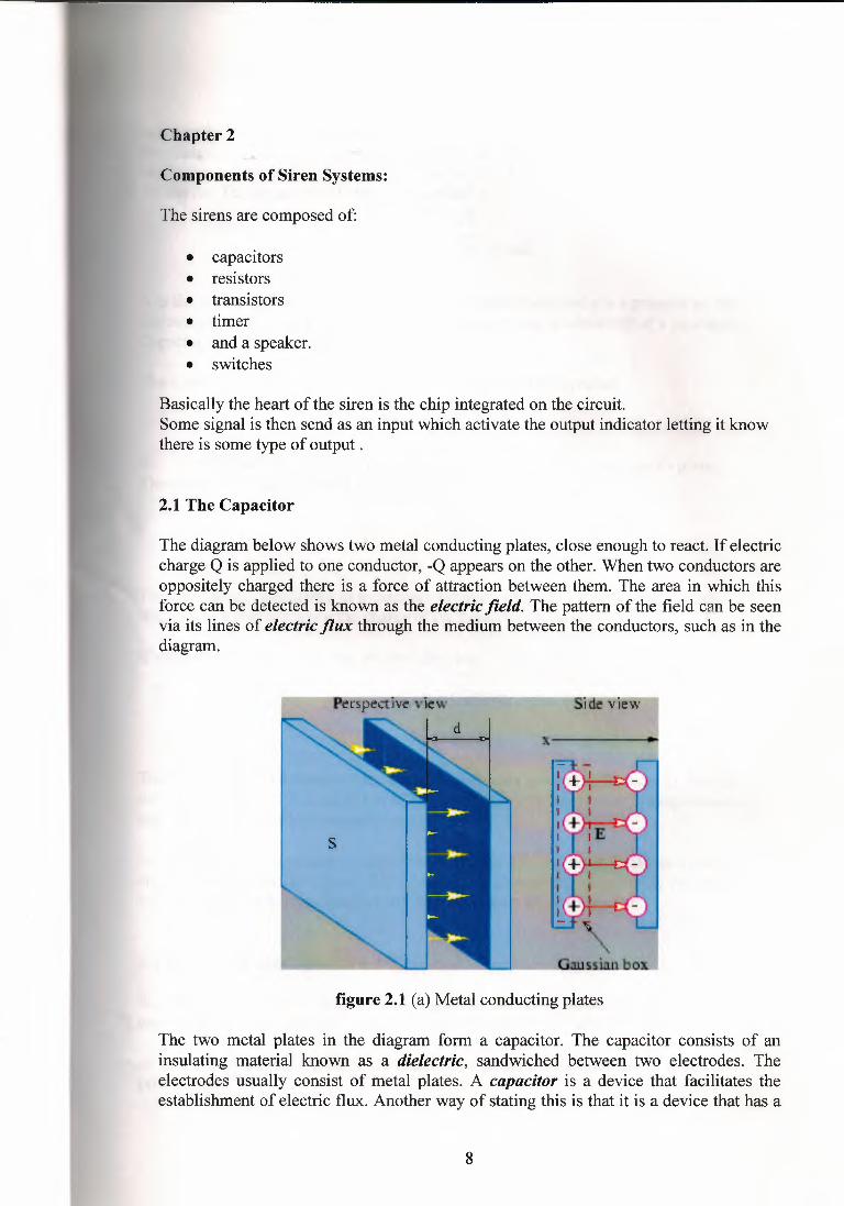
The diagram below shows two metal conducting plates, close enough to react. If electriccharge Q is applied to one conductor, -Q appears on the other. When two conductors areoppositely charged there is a force of attraction between them. The area in which thisforce can be detected is known as the electric field. The pattern of the field can be seenvia its lines of electric flux through the medium between the conductors, such as in thediagram.
figure 2.1 (a) Metal conducting plates
The two metal plates in the diagram form a capacitor. The capacitor consists of aninsulating material known as a dielectric, sandwiched between two electrodes. Theelectrodes usually consist of metal plates. A capacitor is a device that facilitates theestablishment of electric flux. Another way of stating this is that it is a device that has a
8
for storing charge. The lines of electric flux are in fact directly proportional toharge. The amount of electric flux set up or the amount of charge stored dependse size of the electrodes, the properties of the dielectric and the applied voltage toevice. The capacitance is therefore defined as C
A C = &- d farads
A is the area of the plates, d is the separation between them and s is a property of the· lectric known as the permittivity. It is analogous to the conductivity of a conductor.
Capacitance, C, is measured in farads.
The presence of charge gives rise to a voltage V across the capacitor.
Q=CV
~ voltage across the capacitor is linearly proportional to the charge on its plates.Therefore the capacitance of a device can also be defined as follows:
CQV farads
The farad is the capacitance of a capacitor between whose electrodes there is a potentialdifference of one volt when the charge of the capacitor is one coulomb.
If we differentiate Q = CV, we get the following
dQ/dt = C dV/dt=>
i=CdV/dt
The rate at which the charge on the capacitor increases is equal to the current flowinginto the capacitance. A capacitor in a DC circuit will have no current flowing through itand therefore behave like an open circuit.
In texts the ideal capacitor is sometimes referred to. The ideal capacitor retains thestored charge once the source that was used to charge the capacitor is removed. Inreality the charge from a capacitor will leak once the source is removed.
2.1.1 Energy in the Capacitor
As stated already the capacitor stores energy. We can derive an expression for theenergy stored in the capacitor. Suppose a capacitor is initially uncharged.
At t=O, v(t) is applied. Recall the expression for power (introduced during a tutorial)p(t) = v(t)i(t)
9
E J, p(t)dt s:v(t)i(t)dt
E f t dv0
vC dtdt
E f t 1 d 2-C -(v )
o 2 d t
1 2 1 E = 2C[v(t)]- 2C[v(t
o)] 21 2C[v(t)]2
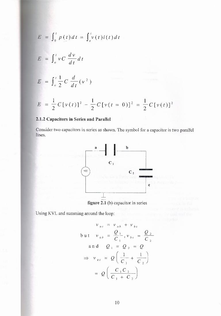
2.1.2 Capacitors in Series and Parallel
Consider two capacitors in series as shown. The symbol for a capacitor is two parallellines.
a b
v(t)
C
figure 2.1 (b) capacitor in series
Using KVL and summing around the loop:
and
10
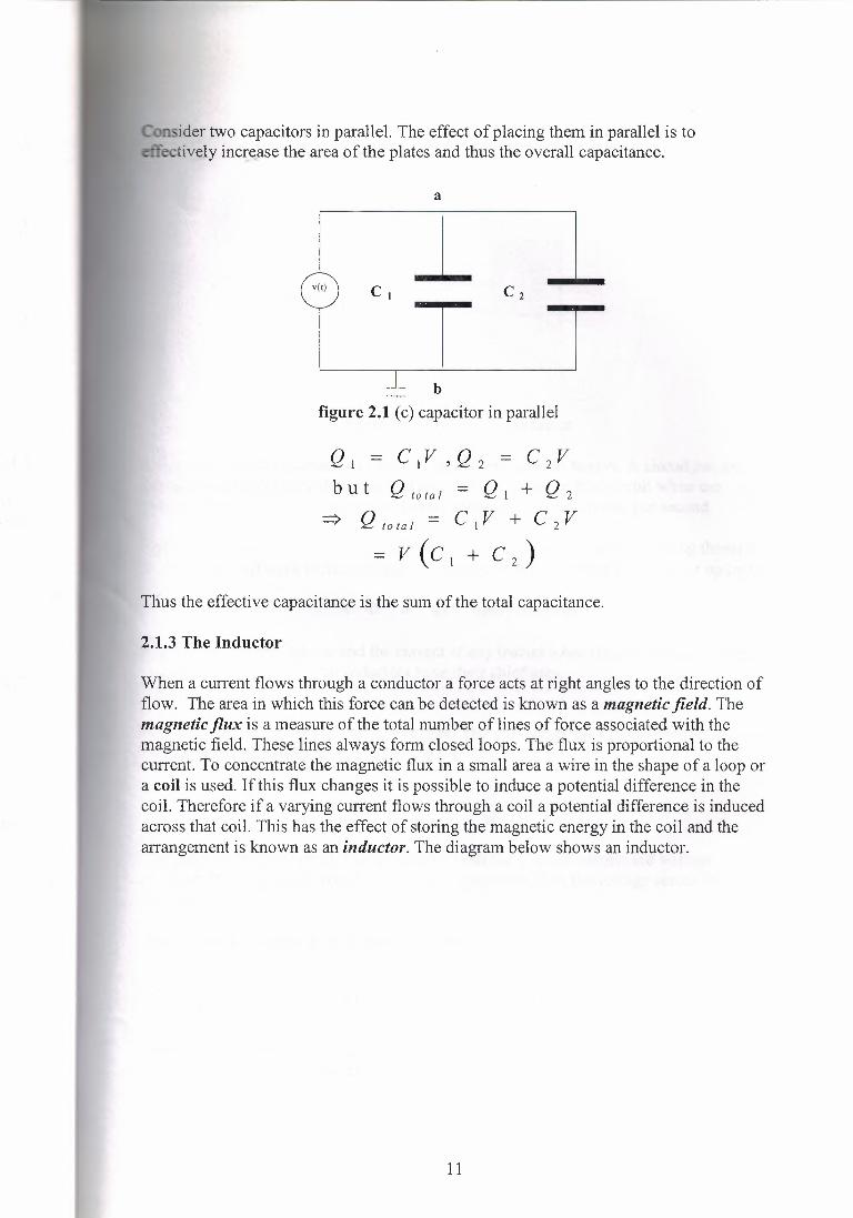
itler two capacitors in parallel. The effect of placing them in parallel is toeffectively increase the area of the plates and thus the overall capacitance.
a
•(<)\ .İ,Cı T c ,
b figure 2.1 (c) capacitor in parallel
QI = CIV ,Q2 = C2Vb U t Q total = Q I + Q 2
=> Q to ta I = C I V + C 2 V
=V(C1+C2)
Thus the effective capacitance is the sum of the total capacitance.
2.1.3 The Inductor
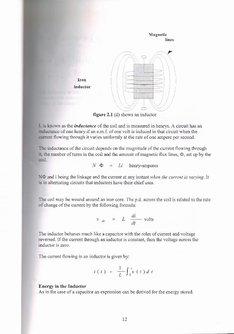
When a current flows through a conductor a force acts at right angles to the direction offlow. The area in which this force can be detected is known as a magnetic field. Themagnetic flux is a measure of the total number of lines of force associated with themagnetic field. These lines always form closed loops. The flux is proportional to thecurrent. To concentrate the magnetic flux in a small area a wire in the shape of a loop ora coil is used. If this flux changes it is possible to induce a potential difference in thecoil. Therefore if a varying current flows through a coil a potential difference is inducedacross that coil. This has the effect of storing the magnetic energy in the coil and thearrangement is known as an inductor. The diagram below shows an inductor.
11
Magneticlines
Iron
inductor
figure 2.1 (d) shows an inductor
· - known as the inductance of the coil and is measured in henrys. A circuit has anuctance of one henry if an e.m.f. of one volt is induced in that circuit when theent flowing through it varies uniformly at the rate of one ampere per second.
e inductance of the circuit depends on the magnitude of the current flowing throughthe number oftums in the coil and the amount ofmagnetic flux lines, <D, set up by the
coil.N <D = Li henry-amperes
~<D and i being the linkage and the current at any instant when the current is varying. Itis in alternating circuits that inductors have their chief uses.
The coil may be wound around an iron core. The p.d. across the coil is related to the rateof change of the current by the following formula:
V ab = L di~ volts
The inductor behaves much like a capacitor with the roles of current and voltagereversed. If the current through an inductor is constant, then the voltage across theinductor is zero.
The current flowing in an inductor is given by:
1 f ıi(t) = - v(t)dtL o
Energy in the InductorAs in the case of a capacitor an expression can be derived for the energy stored.
12
I: p(t)dt f :v(t)i(t)dt
f I di0
L dt i(t)dt
1 2 L i2
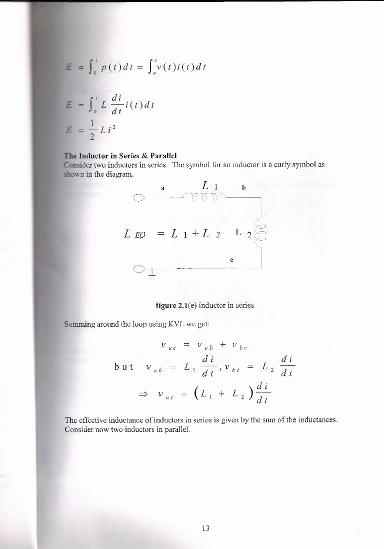
e Inductor in Series & Parallelnsider two inductors in series. The symbol for an inductor is a curly symbol aswn in the diagram.
a Lı b
L EQ L 1 + L 2
figure 2.l(e) inductor in series
umming around the loop using KVL we get:
The effective inductance of inductors in series is given by the sum of the inductances.Consider now two inductors in parallel.
13
o-- J l 1L EQ =~ Lı r L 2 _l_ + _1
L ı L2 I• •o
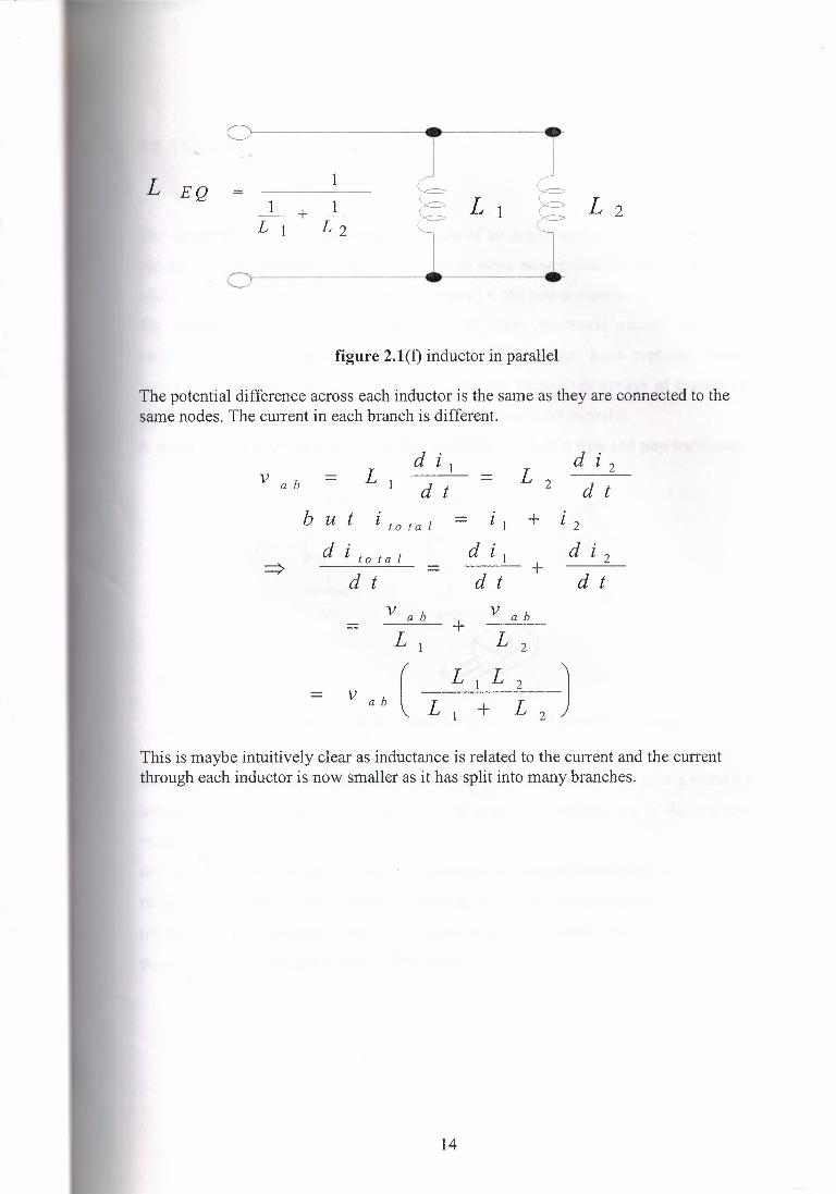
figure 2.l(f) inductor in parallel
The potential difference across each inductor is the same as they are connected to thesame nodes. The current in each branch is different.
Lıd i l
L ıd i 2
V ab - - --d t d t
b u t l total - l I + l 2
d i to tal d i d l 2I +-d t d t d t
V ab + V ab
L, L ı
V ,b ( L ı L 2 )
L ı + L z
This is maybe intuitively clear as inductance is related to the current and the currentthrough each inductor is now smaller as it has split into many branches.
14
Transistor
e transistor is the most important example of an active element. It is a device that
amplify and produce an output signal with more power than the input signal. The
additional power comes from an external source i.e. the power supply.
The transistor is the essential ingredient of every electronic circuit: amplifiers,
oscillators and computers. Integrated circuits (ICs), which have replaced circuits
onstructed from individual, discrete transistors, are themselves arrays of transistors
and other components built as a single chip of semiconductor material.
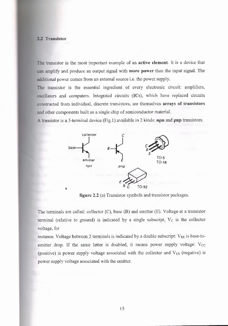
A transistor is a 3-temıinal device (Fig.1) available in 2 kinds: npn and pnp transistors.
T0-5T0-18
npn
~~ B C T0-92
figure 2.2 (a) Transistor symbols and transistor packages.
The terminals are called: collector (C), base (B) and emitter (E). Voltage at a transistor
terminal (relative to ground) is indicated by a single subscript, Vc is the collector
voltage, for
instance. Voltage between 2 terminals is indicated by a double subscript: VBE is base-to
emitter drop. If the same letter is doubled, it means power supply voltage: Vcc
(positive) is power supply voltage associated with the collector and VEE (negative) is
power supply voltage associated with the emitter.
15
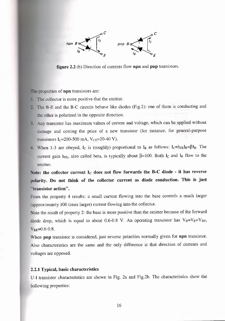
figure 2.2 (b) Direction of currents flow npn and pnp transistors.
operties of npn transistors are:
The collector is more positive that the emitter.
The B-E and the B-C circuits behave like diodes (Fig.2): one of them is conducting and
the other is polarized in the opposite direction.
Any transistor has maximum values of current and voltage, which can be applied without
damage and costing the price of a new transistor (for instance, for general-purpose
transistors le=200-500 mA, VCE=20-40V).
When 1-3 are obeyed, le is (roughly) proportional to lB as follows: le=hFElB=~lB. The
current gain hFE, also called beta, is typically about ~=100. Both le and 18 flow to the
emitter._ •ote: the collector current le does not flow forwards the B-C diode - it has reverse
polarity. Do not think of the collector current as diode conduction. This is just
"transistor action".From the property 4 results: a small current flowing into the base controls a much larger
(approximately 100 times larger) current flowing into the collector.
Note the result of property 2: the base is more positive than the emitter because of the forward
diode drop, which is equal to about 0.6-0.8 V. An operating transistor has VB=VE+VBE,
VBE=0.6-0.8.When pnp transistor is considered, just reverse polarities normally given for npn transistor.
Also characteristics are the same and the only difference is that direction of currents and
voltages are opposed.
2.2.1 Typical, basic characteristicsU-l transistor characteristics are shown in Fig. 2a and Fig.2b. The characteristics show the
following properties:
16
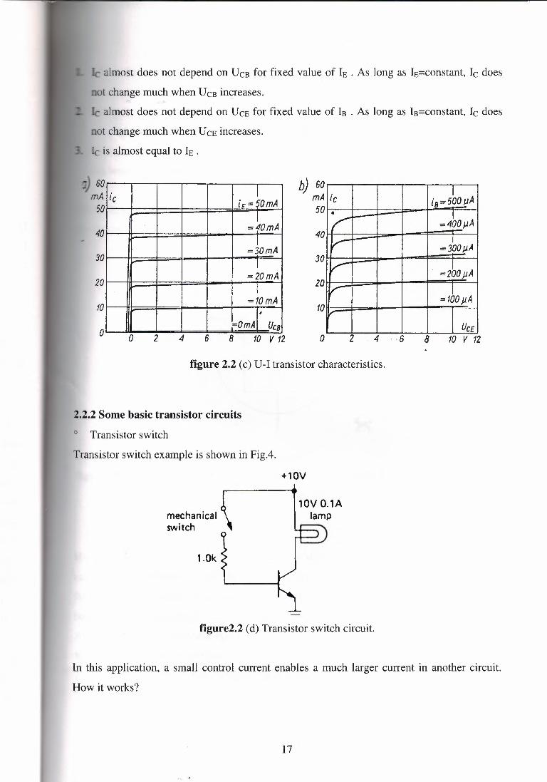
almost does not depend on UCB for fixed value of IE . As long as IE=constant, le does
ot change much when UCB increases.
le almost does not depend on Urn for fixed value of 18 . As long as I8=constant, le does
not change much when Urn increases.
le is almost equal to IE .
'"J 60 mA
50
b) 60 mA 50
40
1ic ic == 50mA I
=40mA I
=30mA l
== 20 mA l
=10mA l
;=OmAl1 Ucs l
6
ic Iia=500 µA
• I/ =400µA
v- I=300µA
V . ='<2bo µA V I
=100µA V
I Uc£
40
30 30
20 20
10 10
o 2 o 4 6 8 o 210 V 12 4 8 10 V 12
figure 2.2 (c) U-I transistor characteristics.
2.2.2 Some basic transistor circuitso Transistor switch
Transistor switch example is shown in Fig.4.
+lOV
mechanical switch
lOV 0.1Alamp
1.0k
figure2.2 (d) Transistor switch circuit.
In this application, a small control current enables a much larger current in another circuit.
How it works?
17
e mechanical switch is opened, there is no base current, therefore (see rule 4)
- no collector current. The lamp is off.
e mechanical switch is closed, the base rises to 0.6 volts (base-emitter diode is
.._~rrıconducting, emitter is at ground voltage level).
ector is more positive than the emitter is (see rule 1) the collector current enables
p to emit light.
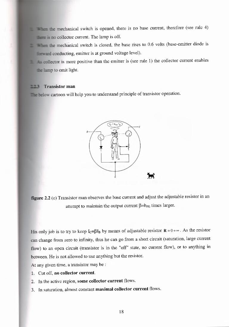
Transistor manow cartoon will help you to understand principle of transistor operation.
C
E
figure 2.2 (e) Transistor man observes the base current and adjust the adjustable resistor in an
attempt to maintain the output current ~=hFE times larger.
His only job is to try to keep Ic=~IBby means of adjustable resistor R =0+00• As the resistor
can change from zero to infinity, thus he can go from a short circuit (saturation, large current
flow) to an open circuit (transistor is in the "off" state, no current flow), or to anything in
between. He is not allowed to use anything but the resistor.
At any given time, a transistor may be :
1. Cut off, no collector current.
2. In the active region, some collector current flows.
3. In saturation, almost constant maximal collector current flows.
18

2.2.4 Emitter follower
Fig.6 shows an example of an emitter follower.
+10V
\
R
figure 2.2 (f) Emitter follower.
_The output voltage (emitter) follows the input voltage (base), less one diode drop:
VE=VB-0.6 volt.
The output is replica of the input, but 0.6 volt less positive. The main features:
ı. Emitter follower has no voltage gain, but it has current gain, therefore it has
power gam.
ıı. The most important feature of emitter follower is that it has input resistance
much larger than its output resistance.
This circuit requires less power from signal source to drive a receiver (a load) that it
would be in case if the signal source drove the receiver (the load) directly.
In general the loading effect causes a reduction of signal (as you have discussed earlier).
19
unloaded
Vin 6~unloaded
~ ~~:·l
loaded
Vout loaded
Rıoad
ground
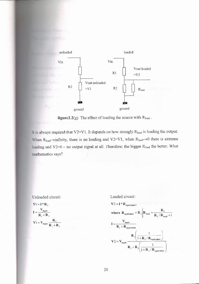
fıgure2.2(g) The effect of loading the source with Rıoad .
Unloaded circuit:
Vl=l*R2
I= V;npuıa, +R2
It is always required that V2=Vl. It depends on how strongly Rıoad is loading the output.
When Rıoad-+infınity,there is no loading and V2=Vl, when Rıoad-+Ü there is extreme
loading and V2=0 - no output signal at all. Therefore: the bigger Rıoad the better. What
mathematics says?
R1
ground
Loaded circuit:
V2 = I -ı, Reqııivalent'
where Requivaıenı =R211Rıoad = R2/:1:.d +l
VinputI=
R1 + Requivalent
R{} + R2 f ~equivalent)V 2 = V;npuı [ 1 )
n, +R2 l+R2 /Requivalent
20
Conclusion: When R,oact ~ ex:;, then Requivaıenı ~ R2 and V2 ~ V1
The emitter follower is the circuit, which has R,0.ct ~ a: .
Emitter follower as voltage regulator
The simplest regulated supply of voltage is a zen er diode. The zener diode is an element
for which the ratio V/I is not constant (as it is for resistance R) but it depends on
particular value of V. It is important to know how the resulting zener voltage will
change with applied current, This is a measure of its "regulation" against changes in
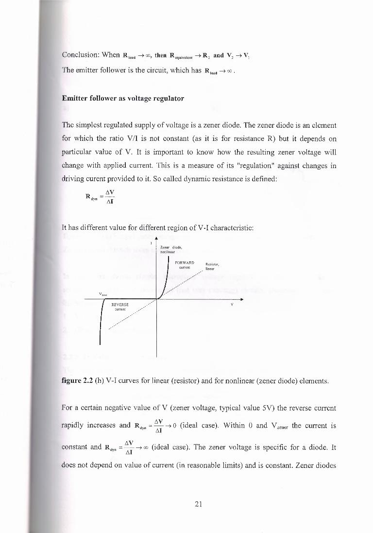
driving curent provided to it. So called dynamic resistance is defined:
R =ı'lVdyn I'll
It has different value for different region ofV-I characteristic:
Zener diode,nonlinear
FORWARD Resistor,linearcurrent
REVERSE _,//current ,,.,..-
/ /
,//,,,/
V
figure 2.2 (h) V-I curves for linear (resistor) and for nonlinear (zener diode) elements.
For a certain negative value of V (zener voltage, typical value 5V) the reverse current
rapidly increases and Rdyn = tıV ~ O (ideal case). Within O and Yzener the current isM
constant and Rctvn = tıv ~ a: (ideal case). The zener voltage is specific for a diode. It- M
does not depend on value of current (in reasonable limits) and is constant. Zener diodes
21
with reverse current are able to keep constant zener voltage even if the reverse current
changes its value.
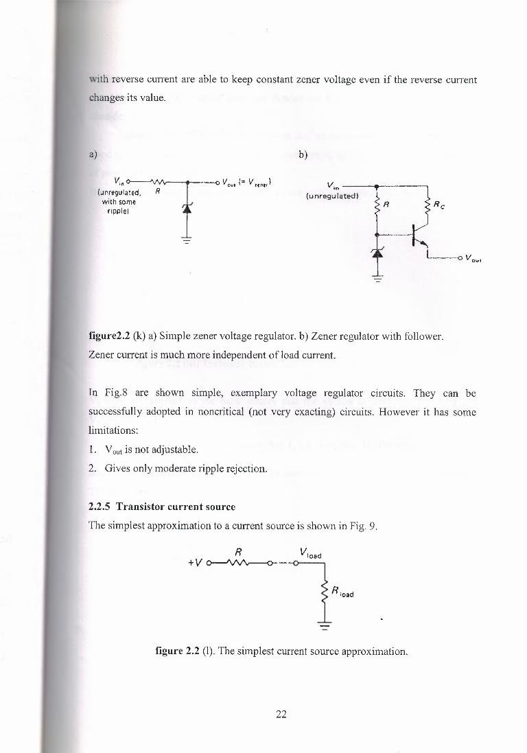
a) b)
Vin~(unregulated, R Vouı (= V mt,)
with someripple)
Vin ---------,
(unregulated)
o vouı
figure2.2 (k) a) Simple zener voltage regulator. b) Zener regulator with follower.
Zener current is much more independent of load current.
In Fig.8 are shown simple, exemplary voltage regulator circuits. They can be
successfully adopted in noncritical (not very exacting) circuits. However it has some
limitations:
1. Vout is not adjustable.
2. Gives only moderate ripple rejection.
2.2.5 Transistor current source
The simplest approximation to a current source is shown in Fig. 9.
Rıoad
figure 2.2 (I). The simplest current source approximation.
22
As long as Rıoact<<R (which means Vıoact<<V) the current I is nearly constant and is
equal to I=V/R. The current does not depend on Rıoa<l therefore the circuit can be
consider as
current source. The simplest solution has an inconvenience: in order to make
good approximation of current source it is necessary to use large voltages. It causes lots
of power dissipation in the resistor.
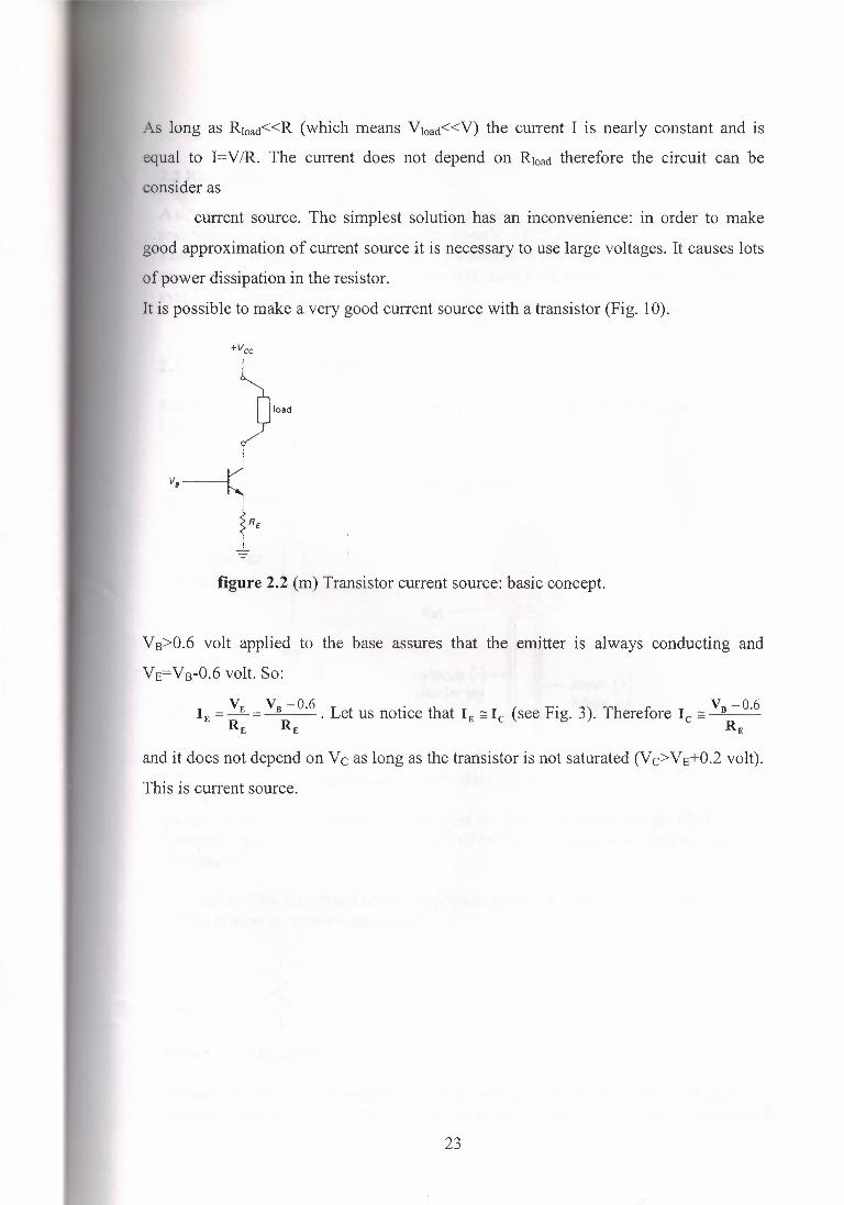
It is possible to make a very good current source with a transistor (Fig. 10).
load
figure 2.2 (m) Transistor current source: basic concept.
VB>0.6 volt applied to the base assures that the emitter is always conducting and
VE=VB-0.6volt. So:
VE VB -0.6 L . h ( F" 3) Th fı VB -0.6IE=-= . et us notıce t at IE~ le see ıg. . ere ore le c::::: ~--RE RE RE
and it does not depend on Ve as long as the transistor is not saturated (Vc>VE+0.2volt).
This is current source.
23
2.3 Resistance
A device that uses electrical energy is called a load. Loads always have someresistance; and a voltage drop across the, since V = E/Q. (If Et, then Vt)Resistance describes the difficulty that electrons have moving through a material.Allmaterials have resistance (except superconductors).Resistance is measured in Ohms,symbol Q (omega).
2.3.1 What do resistors do?
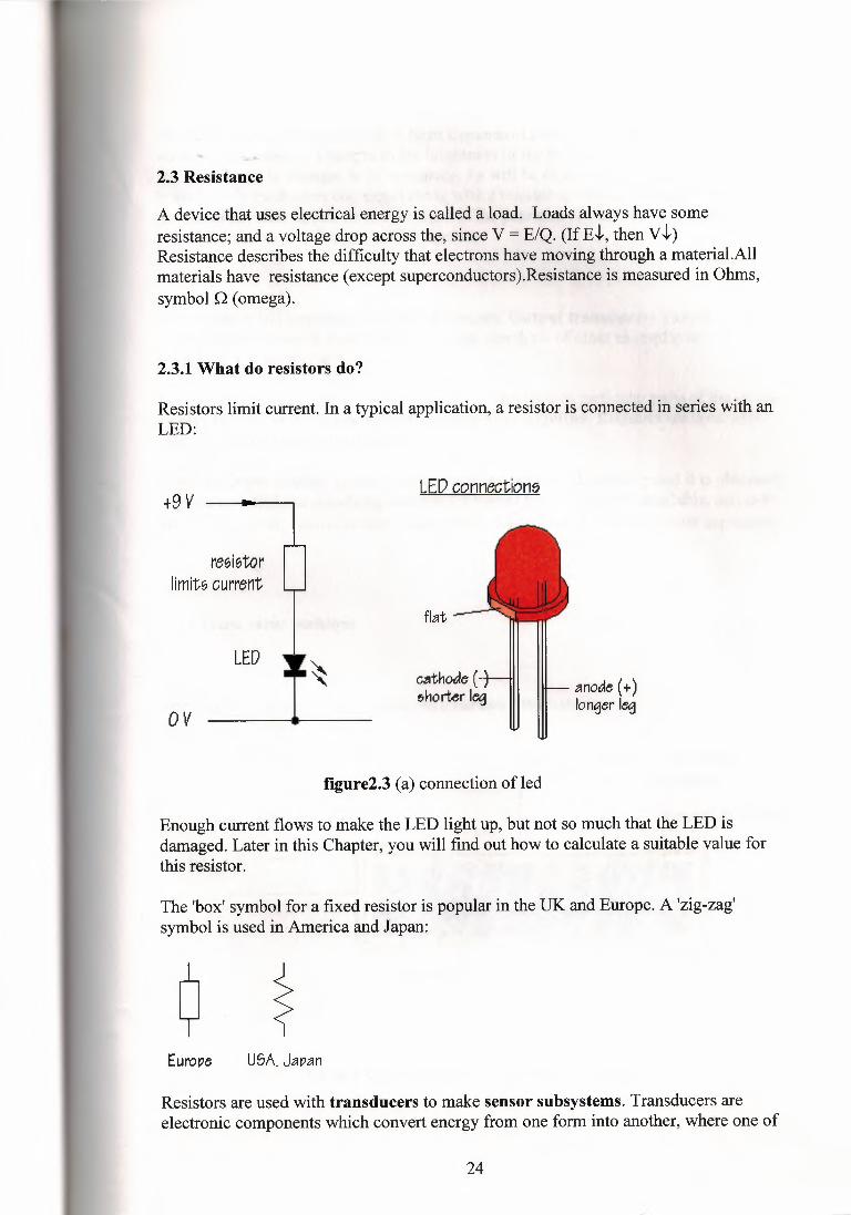
Resistors limit current. In a typical application, a resistor is connected in series with anLED:
+9 V LED connectione
resistorlimits current
flat
LEDcııtnode (ehorter leg anode (+)
longer legov
figure2.3 (a) connection ofled
Enough current flows to make the LED light up, but not so much that the LED isdamaged. Later in this Chapter, you will find out how to calculate a suitable value forthis resistor.
The 'box' symbol for a fixed resistor is popular in the UK and Europe. A 'zig-zag'symbol is used in America and Japan:
Europe USA. Jaı:ıan
Resistors are used with transducers to make sensor subsystems. Transducers areelectronic components which convert energy from one form into another, where one of
24
the forms of energy is electrical. A light dependent resistor, or LDR, is an example ofan input transducer. Changes in the brightness of the light shining onto the surface ofthe LDR result in changes in its resistance. As will be explained later, an inputtransducer is most often connected along with a resistor to to make a circuit called apotential divider. In this case, the output of the potential divider will be a voltagesignal which reflects changes in illumination.
Microphones and switches are input transducers. Output transducers includeloudspeakers, filament lamps and LEDs. Can you think of other examples oftransducers of each type?
In other circuits, resistors are used to direct current flow to particular parts of the circuit,or may be used to determine the voltage gain of an amplifier. Resistors are used withcapacitors to introduce time delays.
Most electronic circuits require resistors to make them work properly and it is obviouslyimportant to find out something about the different types of resistor available, and to beable to choose the correct resistor value, in O, kQ, or MO, for a particular application
2.3.2 Fixed value resistors
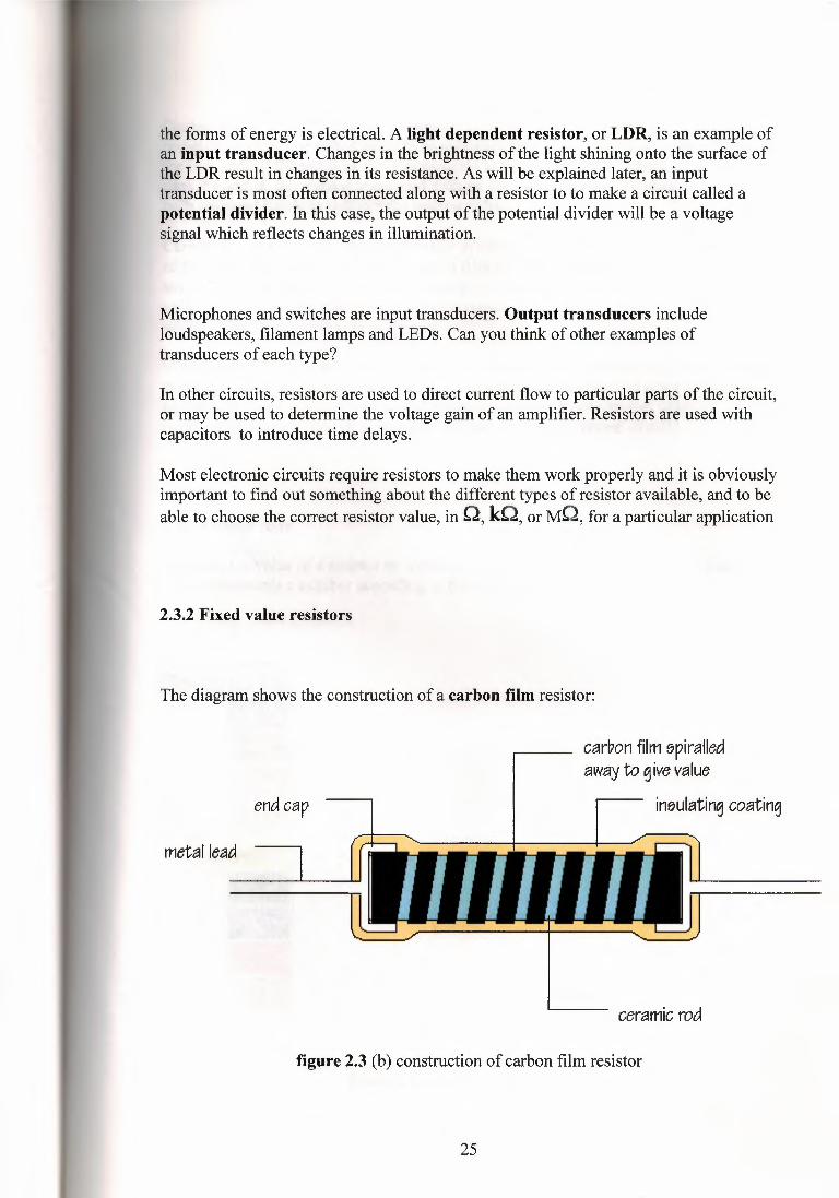
The diagram shows the construction of a carbon film resistor:
carbon film 11piralledaway to give value
in11ulating coatingend cap
metal lead
ceramic rod
figure 2.3 (b) construction of carbon film resistor
25
During manufacture, a thin film of carbon is deposited onto a small ceramic rod. Theresistive coating is spiralled away in an automatic machine until the resistance betweenthe two ends of the rod is as close as possible to the correct value. Metal leads and endcaps are added, the resistor is covered with an insulating coating and finally paintedwith coloured bands to indicate the resistor value.
Carbon film resistors are cheap and easily available, with values within ±10% or ±5%of their marked, or 'nominal' value. Metal fılın andmetal oxide resistors are made in asimilar way, but can be made more accurately to within ±2% or ±1 % of their nominalvalue. There are some differences in performance between these resistor types, but nonewhich affect their use in simple circuits.
Wirewound resistors are made by winding thin wire onto a ceramic rod. They can bemade extremely accurately for use in multirneters, oscilloscopes and other measuringequipment. Some types of wirewound resistors can pass large currents wihtoutoverheating and are used in power supplies and other high current circuits.
2.3.3 Colour code
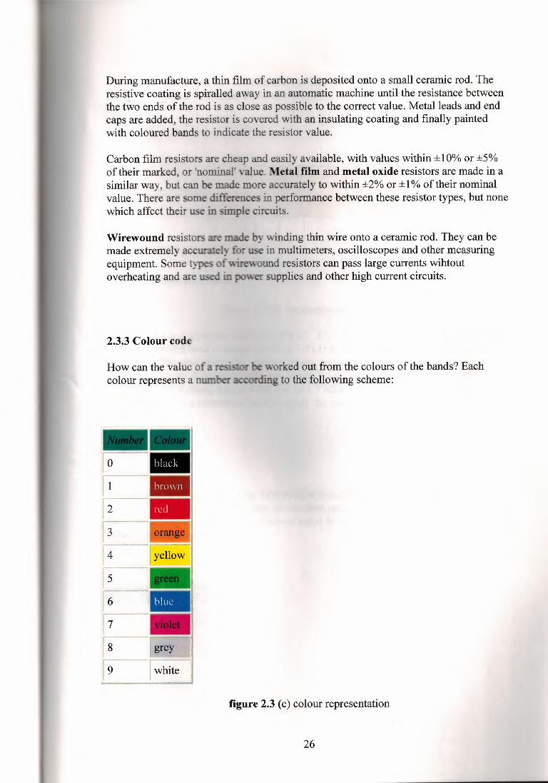
How can the value of a resistorcolour represents a num
worked out from the colours of the bands? Eachording to the following scheme:
o -1 -2
3
4
5
figure 2.3 (c) colour representation
26
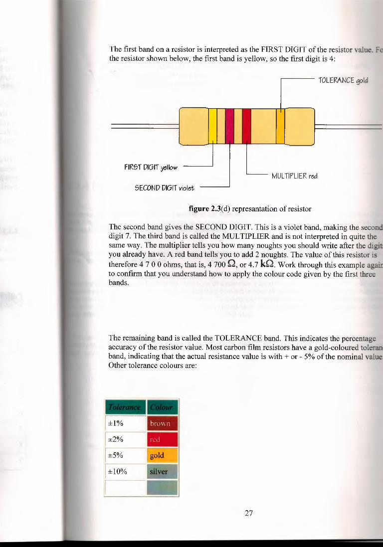
The first band on a resistor is interpreted as the FIRST DIGIT of the resistor value. Fothe resistor shown below, the first band is yellow, so the first digit is 4:
TOLERANCE gold
FIRST DIGIT yellowMULTIPLIER red
SECOND DIGIT violet
figure 2.3(d) represantation of resistor
The second band gives the SECOND DIGIT. This is a violet band, making the seconddigit 7. The third band is called the MULTIPLIER and is not interpreted in quite thesame way. The multiplier tells you how many noughts you should write after the digityou already have. A red band tells you to add 2 noughts. The value of this resistor istherefore 4 7 O O ohms, that is, 4 700 O, or 4.7 kO. Work through this example agairıto confirm that you understand how to apply the colour code given by the first threebands.
The remaining band is called the TOLERANCE band. This indicates the percentageaccuracy of the resistor value. Most carbon film resistors have a gold-coloured toleranband, indicating that the actual resistance value is with+ or - 5% ofthe nominal value.Other tolerance colours are:
[±10%
27
When you want to read off a resistor value, look for the tolerance band, usually gold,and hold the resistor with the tolerance band at its right hand end. Reading resistorvalues quickly and accurately isn't difficult, but it does take practice!
3.4 Resistors
istors, like diodes and relays, are another of the electrical components that should have a section in the installer'sbin. They have become a necessity for the mobile electronics installer, whether it be for door locks, timing circuits,
ote starts, or just to discharge a stiffening capacitor.
istors are components that resist the flow of electrical current. The higher the value of resistance (measured ins) the lower the current will be.
istors are color coded. To read the color code of a common 4 band 1 Kohm resistor with a 5% tolerance, start at thesite side of the GOLD tolerance band and read from left to right. Write down the corresponding number from the
r chart below for the 1st color band (BROWN). To the right of that number, write the corresponding number for theband (BLACK) . Now multiply that number (you should have 1 O) by the corresponding multiplier number of the 3rd
..ldnd (RED)(100). Your answer will be 1000 or 1 K. It's that easy.
a resistor has 5 color bands, write the corresponding number of the 3rd band to the right of the 2nd before youltiply by the corresponding number of the multiplier band. If you only have 4 color bands that include a toleranced, ignore this column and go straight to the multiplier.
28

1 K ohm resistor
I st color band - I ı ı -, - tolerance band2nd color band 3rd color band
The tolerance band is usually gold or silver, but some may have none. Because resistors are not the exact value asindicated by the color bands, manufactures have included a tolorance color band to indicate the accuracy of theesistor. Gold band indicates the resistor is within 5% of what is indicated. Silver= 10% and None= 20%. Others are
shown in the chart below. The 1 Kohm resistor in the example (left), may have an actual measurement any where fron950 ohms to 1050 ohms.
If a resistor does not have a tolerance band, start from the band closest to a lead. This will be the 1st band. If you areunable to read the color bands, then you'll have to use your multimeter. Be sure to zero it out first!
Resistor Color Codes
BancfColorBlackBrown ± 1%
±2 %
10~000Gren 100,000 ± O 5 %
Blue 1.000,000 ± 0.25 %
Vıolet 10,000,000 ± 0.10 %
1100,000,000
White 9 9 9 1,000,000,000
Silvert20%
Gold
None
29
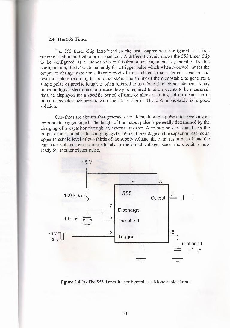
2.4 The 555 Timer
The 555 timer chip introduced in the last chapter was configured as a freerunning astable multivibrator or oscillator. A different circuit allows the 555 timer chipto be configured as a monostable multivibrator or single pulse generator. In thisconfiguration, the IC waits patiently for a trigger pulse which when received causes theoutput to change state for a fixed period of time related to an external capacitor andresistor, before returning to its initial state. The ability of the monostable to generate asingle pulse of precise length is often referred to as a 'one shot' circuit element. Manytimes in digital electronics, a precise delay is required to allow events to be measured,data be displayed for a specific period of time or allow a timing pulse to catch up inorder to synchronize events with the clock signal. The 555 monostable is a goodsolution.
One-shots are circuits that generate a fixed-length output pulse after receiving anappropriate tıigger signal. The length of the output pulse is generally determined by thecharging of a capacitor through an external resistor. A trigger or start signal sets theoutput on and initiates the charging cycle. When the voltage on the capacitor reaches anupper threshold level of two thirds of the supply voltage, the output is turned off and thecapacitor voltage returns immediately to the initial voltage, zero. The circuit is nowready for another trigger pulse.
+5V
4 8I
100 kn ( 555 Output µ_ _JL_
7 - Discharge
1.0 µ= _T. 6Threshold
I 5
--2+5VlJ Trigger
Gnd· (optional)
1 İ_ 0.1 µ'
figure 2.4 (a) The 555 Timer IC configured as a Monostable Circuit
30
The monostable arrangement of components requires only a single resistor andcapacitor. The voltage across the capacitor is sampled on pins 6 and 7. A negativetrigger pulse on pin 2 sends the output (pin 3) high for a time determined by the resistor
and capacitor network. When the capacitor voltage reaches the threshold (2/3 Vcc), theoutput goes low. The on-time Ton is given by
Ton= 1.1 RC.
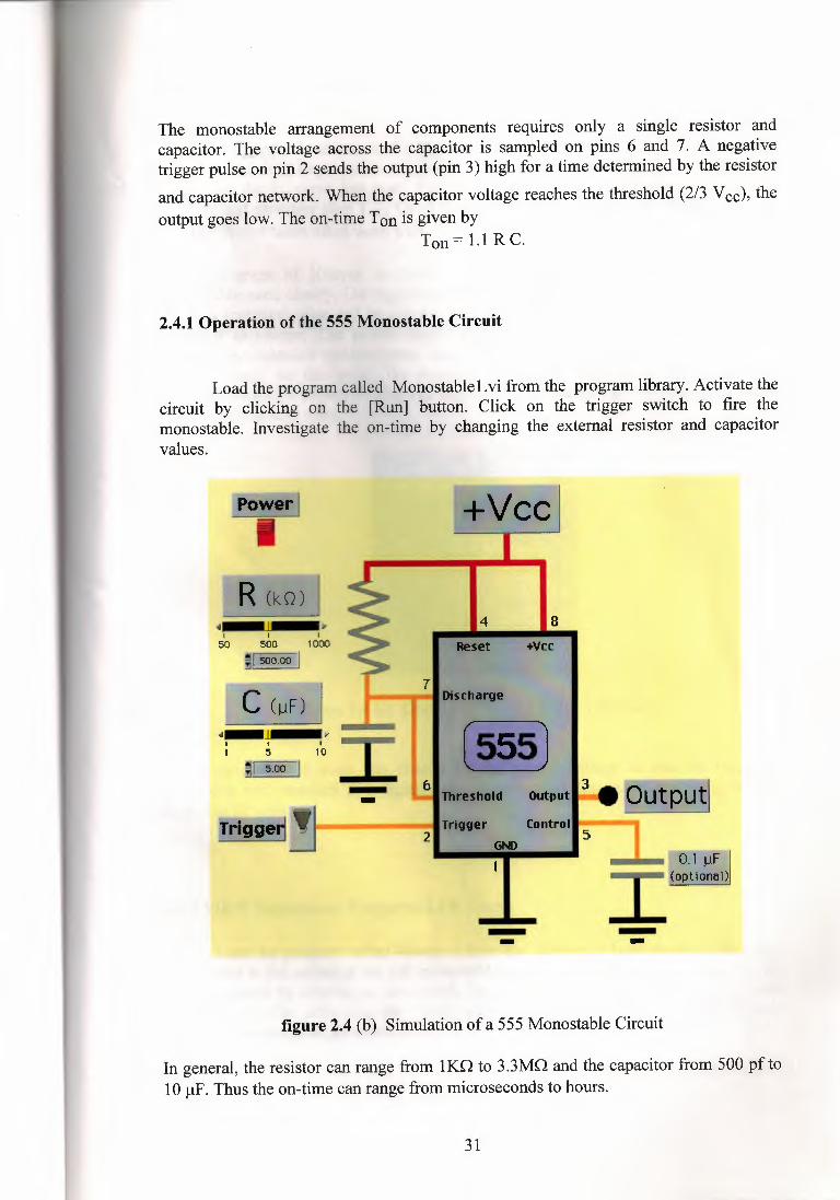
2.4.1 Operation of the 555 Monostable Circuit
Load the program called Monostablel.vi from the program library. Activate thecircuit by clicking on the [Run] button. Click on the trigger switch to fire themonostable. Investigate the on-time by changing the external resistor and capacitorvalues.
+VeePower II
R (kO) l·- ,.I I I50 500 1000
~~I
4 ısReset +Vee
71 Disı:herge
~ '
t>Ithreshold output
Trtııer Control21 G,t>
•••I
--;rrıggerj!J
--figure 2.4 (b) Simulation of a 555 Monostable Circuit
In general, the resistor can range from lKQ to 3.3MQ and the capacitor from 500 pf to10 µF. Thus the on-time can range from microseconds to hours.
31
,-.~~,"ı..~lfo P..
The trigger input is normally high and momentarily bringing it low ~js::,tıretrigger signal. It is important to remember that the trigger input must be brought highagain after the triggered low state. For the 555 timer chip, the trigger pulse must benegative and narrower than Ton· Good design calls for a trigger pulse length about 1/4Ton but shorter times often work well.
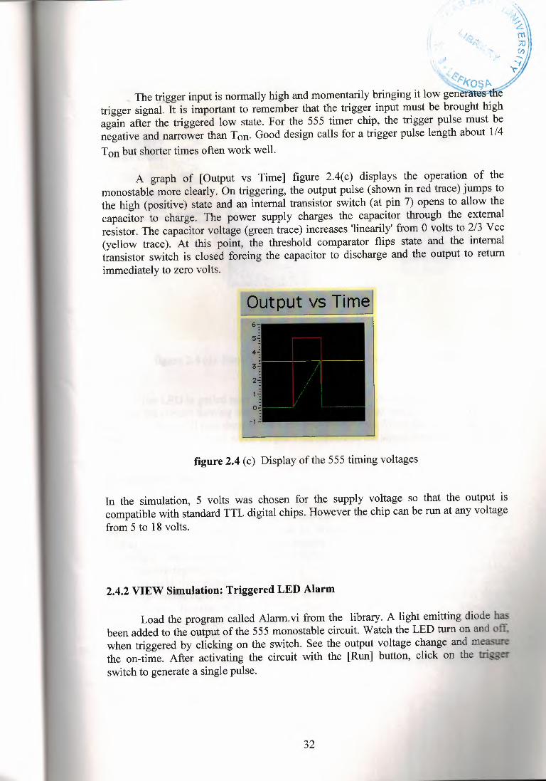
A graph of [Output vs Time] figure 2.4(c) displays the operation of themonostable more clearly. On triggering, the output pulse (shown in red trace) jumps tothe high (positive) state and an internal transistor switch (at pin 7) opens to allow thecapacitor to charge. The power supply charges the capacitor through the externalresistor. The capacitor voltage (green trace) increases 'linearily' from O volts to 2/3 V cc(yellow trace). At this point, the threshold comparator flips state and the internaltransistor switch is closed forcing the capacitor to discharge and the output to returnimmediately to zero volts.
figure 2.4 (c) Display of the 555 timing voltages
In the simulation, 5 volts was chosen for the supply voltage so that the output iscompatible with standard TTL digital chips. However the chip can be run at any voltagefrom 5 to 18 volts.
2.4.2 VIEW Simulation: Triggered LED Alarm
Load the program called Alarm.vi from the library. A light emitting diode hasbeen added to the output of the 555 monostable circuit. Watch the LED tum on and off.when triggered by clicking on the switch. See the output voltage change and measurethe on-time. After activating the circuit with the [Run] button, click on the triswitch to generate a single pulse.
32
R (kO) ,~I
1000
<II
10I
51
~I 1.00 I -~-,, -rlgge~!J
4 8Reset +Vee
7Dlsehorge
Trigger ControlGND
52
O.I µF--· (opt1onııl)
-- --figure 2.4 (d) Simulation of a 555 Monostable with a LED Output
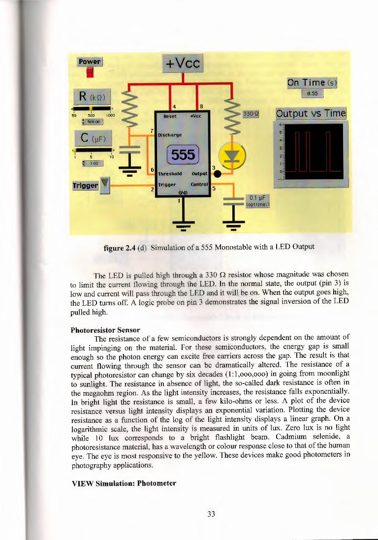
The LED is pulled high through a 330 Q resistor whose magnitude was chosento limit the current flowing through the LED. In the normal state, the output (pin 3) islow and current will pass through the LED and it will be on. When the output goes high,the LED turns off. A logic probe on pin 3 demonstrates the signal inversion of the LEDpulled high.
Photoresistor SensorThe resistance of a few semiconductors is strongly dependent on the amount of
light impinging on the material. For these semiconductors, the energy gap is smallenough so the photon energy can excite free carriers across the gap. The result is thatcurrent flowing through the sensor can be dramatically altered. The resistance of atypical photoresistor can change by six decades (1: l ,000,000) in going from moonlightto sunlight. The resistance in absence of light, the so-called dark resistance is often inthe megaohm region. As the light intensity increases, the resistance falls exponentially.In bright light the resistance is small, a few kilo-ohms or less. A plot of the deviceresistance versus light intensity displays an exponential variation. Plotting the deviceresistance as a function of the log of the light intensity displays a linear graph. On alogarithmic scale, the light intensity is measured in units of lux. Zero lux is no lightwhile 1 O lux corresponds to a bright flashlight beam. Cadmium selenide, aphotoresistance material, has a wavelength or colour response close to that of the humaneye. The eye is most responsive to the yellow. These devices make good photometers inphotography applications.
VIEW Simulation: Photometer
33
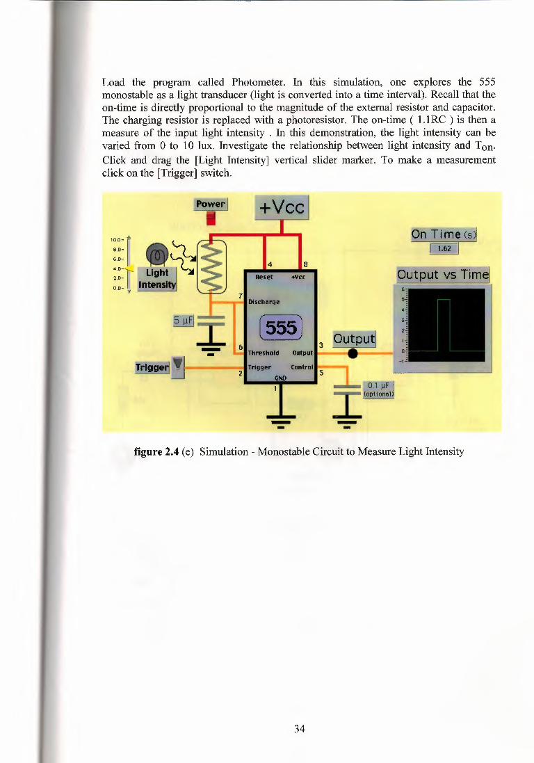
Load the program called Photometer. In this simulation, one explores the 555monostable as a light transducer (light is converted into a time interval). Recall that theon-time is directly proportional to the magnitude of the external resistor and capacitor.The charging resistor is replaced with a photoresistor. The on-time ( l. lRC ) is then ameasure of the input light intensity . In this demonstration, the light intensity can bevaried from O to 1 O lux. Investigate the relationship between light intensity and Ton,Click and drag the [Light Intensity] vertical slider marker. To make a measurementclick on the [Trigger] switch.
Pn Time (s)I~I
4
Reset +Vee ı.,---- I I (555] 15µFJ...,...fıIThreshold Output
Tıiııver Control21 GN)
- -~--~-~--- - -figure 2.4 (e) Simulation - Monostable Circuit to Measure Light Intensity
34
CHAPTER 3:
SAMPLES CİRCUİT
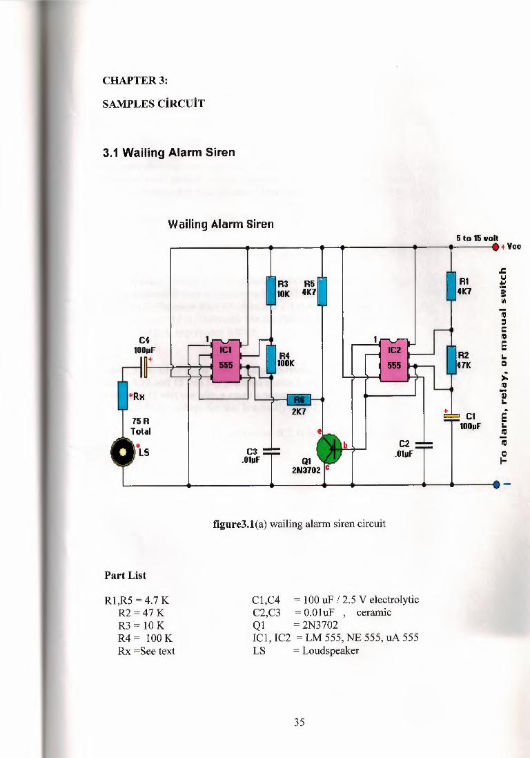
3.1 Wailing Alarm Siren
Wailing Alarm Siren5 to 15 volt
ı ı ı ı • • •+Yee
C4IOOııF
+
*RK
75RTotal
C3.OlııF
R3 R5IOK 4K7
R4IOOK
2K7
Part List
Rl,R5 =4.7 KR2=47KR3 = 10 KR4= 100KRx =See text
C2.Olpf
figure3.l(a) wailing alarm siren circuit
Cl,C4 = 100 uF I 2.5 V electrolyticC2,C3 = O.OluF , ceramicQl = 2N3702ICl, IC2 = LM 555, NE 555, uA 555LS = Loudspeaker
35
RI4K7
R247K
± ClIOOııF
.cu:!:a:"'ıı::ı:ıCıı::ı
Eı.Q.>,.ıı::ı-Illı..Eı.ıı::ı-ıı::ıQı-
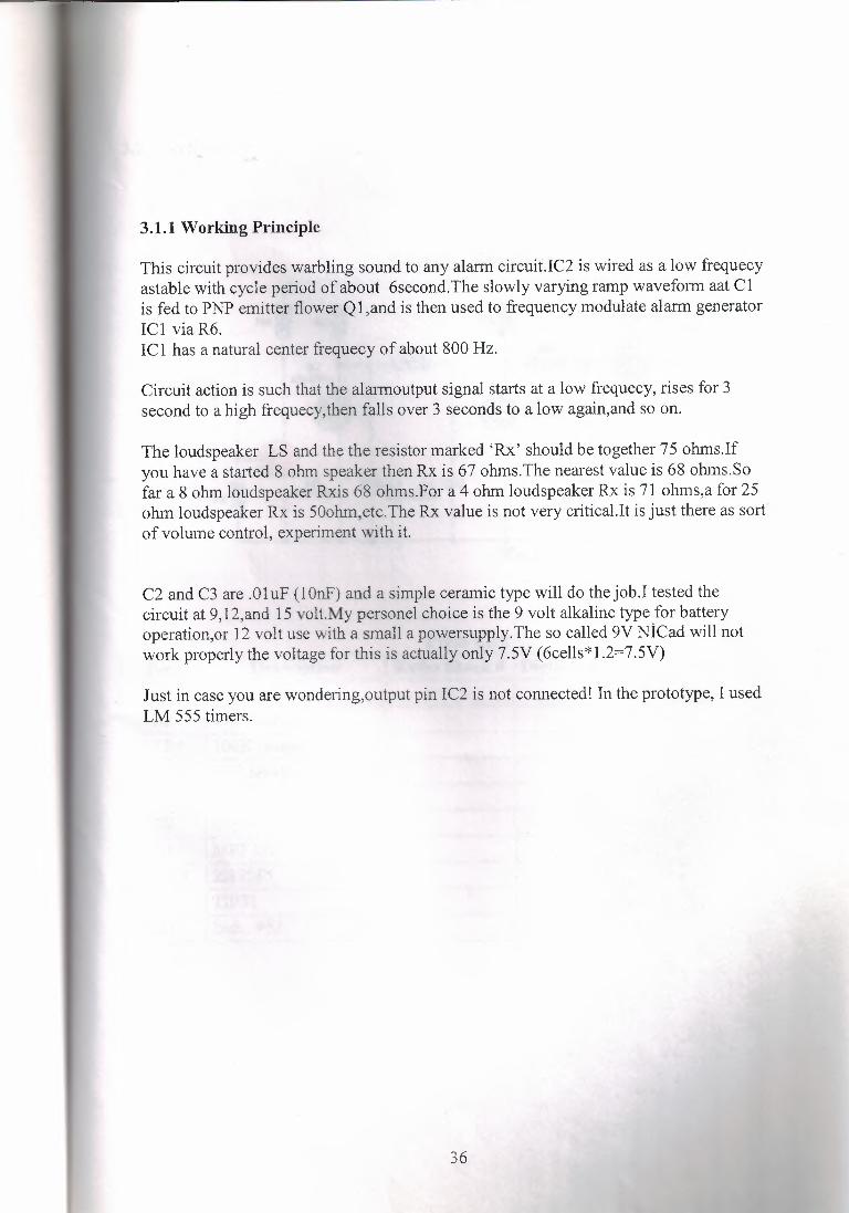
3.1.1 Working Principle
This circuit provides warbling sound to any alarm circuit.IC2 is wired as a low frequecyastable with cycle period of about 6second.The slowly varying ramp waveform aat Clis fed to PNP emitter flower Ql,and is then used to frequency modulate alarm generatorICl via R6.ICl has a natural center frequecy of about 800 Hz.
Circuit action is such that the alarrnoutput signal starts at a low frequecy, rises for 3second to a high frequecy,then falls over 3 seconds to a low again,and so on.
The loudspeaker LS and the the resistor marked 'Rx' should be together 75 ohms.Ifyou have a started 8 ohm speaker then Rx is 67 ohms.The nearest value is 68 ohms.Sofar a 8 ohm loudspeaker Rxis 68 ohms.For a 4 ohm loudspeaker Rx is 71 ohms,a for 25ohm loudspeaker Rx is 50ohm,etc.The Rx value is not very cıitical.It is just there as sortof volume control, experiment with it.
C2 and C3 are .Ol uF (1 OnF) and a simple ceramic type will do the job.I tested thecircuit at 9,12,and 15 volt.My personel choice is the 9 volt alkaline type for batteryoperation,or 12 volt use with a small a powersupply.The so called 9V NİCad will notwork properly the voltage for this is actually only 7.5V (6cells*l.2=7.5V)
Just in case you are wondering,output pin IC2 is not connected! In the prototype, I usedLM 555 timers.
36
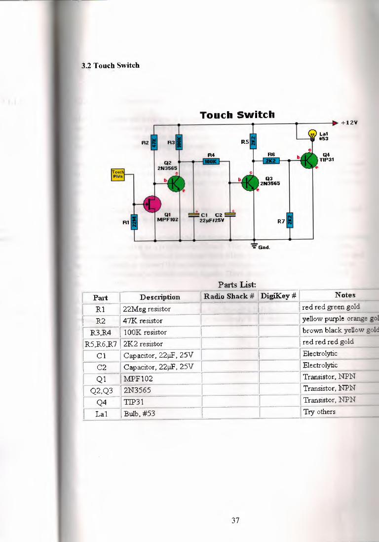
3.2 Touch Switch
Touch Switch
AZ
La1 #53
Q4 TIP31
Q3 ZN3565
R1 Q1
MPF10Z
±_ _l±C1 CZ 22~FIZ5Y R7
":' Gnd.
Parts List:I Part I Description I Radio Shack# I DigiKey # ! NotesI R 1 I 22Meg resistor I red red green goldI R2 I 47K resistor . I yellow purple orange go
I R3,R4 I 100K resistor I brown black yellow gold
IR5,R6,R7 I 2K2 resistor I I I red red red goldI C 1 I Capacitor, 22µF, 25V I ElectrolyticI C2 [ C~pacitor, 22µF, 25V I ElectrolyticI Q 1 I :ıv.ı:PF 102 I Transistor, NPNI Q2,Q3 I 2N3565 I Transistor, NPNI Q4 [ TIP31 I Transistor, NPN
I. La1 I Bulb, #53 I Try others
37
3.2.1 Switching techniques:
Manual switches can have one or a combination of switching actions. In momentary-actionswitches, the operator pushes (pushbutton or toggle) or twists (rotary) the actuating deviceand contacts move to transfer the circuits to the second set of contacts. When the actuatingforce is removed, the actuating device and the contacts return to the original position.
When a maintained-action touch switch is actuated, the contacts move to transfer the circuitsto the second set of contacts. No change takes place until the operator actuates the switch asecond time. Then the touch switch circuit moves to another set of contacts or returns to theoriginal position.
Mechanical-bail switches have separate switching assemblies, which are interlocked so thatactuation of one switch deactivates another.
A capacitive touch switch consists of two conductive layers on opposite sides of an insulatingmaterial such as glass or a printed-circuit board. The touch switch has conductive layers,which create a capacitance that decreases when a layer is touched. Interface circuitry is usedon a touch switch to convert the capacitance and change into a usable switching action todrive logic systems or to switch analog signals. There are several types of touch switchcircuits available.
A membrane touch switch is a simple device in which conductive leads on the underside of aflexible membrane are, at a keystroke, pushed through a hole in a spacer to make contact withconductive leads on a base. Virtually every membrane touch switch can handle loads up toabout 1.5 VA at 5 to 15 V.
38
Conclusion:
Sirens are sound making devices that alert people there is an ec:e:-;;::::.__
is a fire, an earthquake, a tornado, or police, or an ambulance is -
As technology advances some things become absolete, but \\1....,
have the things we have now. Some examples of inventions
technology are how floppy disks, record players, and casse
DVDs, and portable flash drives.
However there are things that only can be improved not rep.ace
sirens which started so long a go and today is even used in tae r_o;.. .•.~_.-J.;.u.._ı__
music. Sirens use different amplitude and frequency to n-rnr.n,
depending in the organization. Sirens are also used for
and automobiles and to make sure equipment are functioniz.g_
I believe that we can improve the functionality of sir
implementing different techniques especially for mo
emergency vehicles with both types of sirens, electro
REFERENCES
[ 1] L.A Geddes, The Direct and the Indirect Measurement of Blood Pressure,Chicago:Year Book Medical Publisher, 1970.
[2] J.G. Webster, Ed., Encyclopedia of Alarm System Devices and Instrumentation,New York: John Wiley
[3] J.Janata, Principles of Electronic Alarm System,New York: Plenum Pres, 1990
[4] B.R Eggins Electronic :An Introduction, Chichester; New York: John Willey 1996
[5] R.Pallas Areny and J.G Webster, Signal and Sensor Conditioning, New York: JohnWilley
[6] W.Göpel, I.Hesse and J.N Zemel, Sensorv; A Comprehensive Survey, Weinheim,Germancy: VCH Verlagsgesellschchaft, 1989
40