NEAR EAST UNIVERSITY Faculty of Engineering
137
- NEAR EAST UNIVERSITY Faculty of Engineering Department of Electrical and Electronic Engineering SHIP ELECTRIC SYSTEMS Graduation Project EE-400 H.Erdem Sayg1 (970575) Ozgiir Cemal Ozerdem Lefkofa-2002
-
Upload
khangminh22 -
Category
Documents
-
view
0 -
download
0
Transcript of NEAR EAST UNIVERSITY Faculty of Engineering
- NEAR EAST UNIVERSITY
Faculty of Engineering
Department of Electrical and Electronic Engineering
SHIP ELECTRIC SYSTEMS
Graduation Project EE-400
H.Erdem Sayg1 (970575)
Ozgiir Cemal Ozerdem
Lefkofa-2002

ACKNOWLEDGEMENTS
First of all, I would like to thank my parents espectially my father for his huge
knowledge and for his endless help. I also wish to thank to Electrical and Electronic
Engineering Department Assistants Mr.Cemal Kavalcioglu for his helps.
I want to thanks seperately first to my supervisor Mr. Ozgur C. Ozerdem for
shearing his experianse with me , to my instructors that during my education they
support me the Dean of Engineering Faculty and Vice-President Prof Dr. Fak:hreddin
MAMEDOV, and everytime from near to me, my dear instructors Chairman of
Electrical and Electronic Department Assoc.Prof.Dr. Adnan Khasman,, Vice Chairman
of Electrical and Electronic Engineering Department Assist. Prof Dr. Kadri
BURUNCUK, Vice-President of University Prof.Dr. Senol BEKTAS, Prof.Haldun
GURMEN, Mr. Mehrdad KHALEDi, Assist. Prof. Dr. Dogan HAKT ANIR
I would like to express my gratitude to the Companies GESAN Ship Electrics
Systems, Group Schneider and, Sanmar Shiping Co. that they gave to me informations and datas about Ship Electrics Systems.
Finally, I want to thanks everybody who helped and supported me come today's and graduated from a University .
.. ~ •
1
·~· 1! ·f
1 l '.,.11 '. !·1\··
J ~(t'': .:~ l •
{}' ~ :·.r
·· ::~ 1 rr.,):
. '•'{~ '
ABSTRACT
One of the most important transportation style is ship transportation. It is the
cheapest way of transporting objects one point to another point. Also the huge amout of
cargo can carryied with this transportation style. But of course there are some rules
which must be agreeds when doing this job. All the countries has their own rules, also it
has a international rules because ships are visiting foreigner countries and these
countries rule's can be different from cur's, at these conditions international rules are valid.
The main thing of these rules mention about safety, because no bady can help
you easly while you are sailling. The second important thing of ship is sea suitability.
We are interesting electrical systems of ships and protection system and devices.
Because even small devices can couse big problems.
In the ships, all the systems must be work in harmoniously, for example fire
alarm system can be control some parts of main electric system, it can be stop the fans
or aircondition etc... or thing about 24 V DC system, it is using accumulator batteries
but batteries are charging with main electric system (generator). These are only small example.
Vessels produce their own electrical power, this can be produce by different
kind of machines ( or technics ), the general they use diesel-electric generators and shaft
generators. The number of generator and power of generator is change according to
ship's diemensions. Some ships can use these generators in parallel operation.
The shaft generators are preferable for big and going far distance vessels.
Because the primary mover of this machine is main engine, and for using shaft
generator revolution of main engine must be stable. We can only get this rpm (rount per
minute) rate while going far distaces or this system is better for picth control ships, to
this system main engine is allways rotating same rpm but propeller's angle is changing.
The energy is disributed with main switchboard, also motors, ligthing system,
air condition etc .. can be able to control from here. Also there is some measurement
device in it like voltmeter, ampermeter, frequency meter, KW meter, we can display
some information with these.
11
. ,,, . \ .. t.~~··1-:;./}
' l..l! ,·j)f5
n1.;'1
d ~ .. ; 73\/i'
· .. -,:·;
.. ,,.
,, ":
•'•.J
. ,;.
INTRODUCTION
This project was talked about rules which must be agreed while constructing the
electrical systems and also safety systems, how the electrical power produce, how the electrical power distribute .
The tests must be done for equipment, which must be done for all the system.
While doing these tests, period and values must be known, next chapters are talking about those things.
This project is 6 chapters and they are explained at the following.
Chapter 1- General Provision; It is talking about short explanation of next
chapters, the capacities of generators, which plans must be submitted, the data's
equipments in the plan, and shortly explanation of basic requirements.
Chapter 2- System Design; this chapter was mentioned about how many
generators will be used and their capacities, shaft generators and their conditions in
stable and variable speed, how will we placing the generators, furthermore emergency
source of electrical power which will operate after failure of other systems.
Chapter 3- Electrical Equipment; this chapter was talked about, the using
equipment in each unity, and giving information of their characteristics.
Chapter 4- Ship Board Installation; this chapter was mentioned about which
equipment must be place where and test of these equipments, furthermore it is giving
information about cables and how can we spread them.
Chapter 5- Special Ships; this chapter was mentioned about special ships, giving
information about these ships, high voltage systems using in the ship and the other systems.
Chapter 6- Explanation of Example Project; with using these information, analysis
the sample ship, which the information was mentioned above chapters, cost analysis of
this ship and some calculations.
The conclusion presents what kind of ship forming at the end of using these
systems, the desires of ship-owners, and future plans for improving these systems.
lll
TABLE OF CONTENTS
·~ .,! X l ·. :t • .
ACKNOWLEDGMENT ABSTRACT INTRODUCTION
1. GENERAL PROVISION
1.1 Organization of Requirements for Electrical Systems
1.2 Applications
1.3 Plans and Data to be Submitted
,,t' I
···'J
1.3.1 System Plan
1.3.2 Installation Plans
1.3.3 Equipment Plans
1.4 Definitions ·')f~.~n:h! i'~
1.4.1 General
1.4.2 Specific
1.5 Basic Requirement
2. SYSTEM DESIGN
2.1 Applications
2.2 Main Source of Electrical Power 2.2.1 Number and Capacity of Generators
2.2.2 Power Supplied by Propulsion Generators
2.2.3 Shaft Generators
2.2.4 Transformer and Converters
2.2.5 Location of Generators
2.2.6 System Arrangement
2.2. 7 Main Switchboard
2.3 Emergency Source of Electrical Power 2.3.1 General
2.3 .2 Location
2.3.3 Emergency Services
2.3 .4 Vessel on Short Duration Voyages
2.3.5 Power Source
2.3.6 Transition Source Power
.)
i .. II ... Ill
1
1
1
1
1
3
4
5
5
5
6
7
7
7
7
8
8
9
9
9
9
10
10
10
11
13
13
15
2.3.7 Emergency Switch Board
2.3.8 Starting Arrangements for Emergency Generator Sets
2.4 Distribution System 2.4 .1 General
2.4.2 Hull Return Systems
2.4.3 Earthed AC Distribution Systems
2.4.4 Cable Sizing
2.4.5 Segregation of Power Circuits
2.4.6 Steering Gear Power Supply Feeders
2.4.7 Lighting System
2.4.8 Ventilation System Circuits
2.4.9 Cargo Space Circuits.
2.4.10 Electric Space Heater Circuits
2.5 System Protection 2.5.1 General
2.5.2 Protection Against Short-Circuit
2.5.3 Protection Against Overload
2.5.4 Coordination of Protective Devices
2.5.5 Load Shedding Arrangement
2.5.6 Protection of Generators
2.5.7 Protection of Feeder Cables.
2.5.8 Protection for Accumulator Batteries
2.5.9 Protection of Motor Circuits
2.5.10 Protection of Transformer Circuit
2.5.11 Protection for Branch Lighting Circuits
2.6 Specific Systems 2.6.1 Shore Connection
2.6.2 Navigation Light System
2.6.3 Interior Communication System
2.6.4 Manually Operated Alarms
2.6.5 Emergency Shutdown Systems
2.6.6 Batery Starting Systems
15
16
17
17
17
17
18
20
20
20
20
21
21
21
21
21
22
23
23
24
25
25
25
27
27
27
27
28
29
30
32
33
3. ELECTRICAL EQUIPMENT 34
3.1 General 34
3.1.1 Applications 34 3.1.2 Standart of Compliance 34 3.1.3 Certification of Equipment 34 3.1.4 Materials and Design 35 3.1.5 Voltage and Frequency Characteristics 35 3.1.6 Enclosures 35 3 .1. 7 Accessibility 35 3 .1. 8 Insulation Material 35 3.1.9 Ambient Tempratures 36
3.2 Rotating Machines 36
3.2.1 Application 36 ,,, I :.<,,r;.; 3.2.2 Definition 36 3.2.3 Rating 37 3.2.4 Overload/Over-Current Capacity 37 3.2.5 Short Circuit Capability 38 3.2.6 Construction 38 3.2.7 Generator Control 40 3.2.8 Testing 42 3.2.9 Certifications 44
3.3 Switchboards, Motor Controllers,etc .. 44
3.3.1 Application 44 3.3.2 Construction, Assembly and Components 44
3.3.3 Main and Emergency Switchboards 46 (\ r I 3.3.4 Motor Controllers 47 3.3.5 Battery Charging Panels 47 3.3.6 Testing and Certification 48
3.4 Transformer and Converters 49
3.4.1 Enclosures 49
3.4.2 Transformer for Essential Services 49 3.4.3 Semiconductor Converters 50
3.5 Cables 51
3.5.1 Standard of Compliance 51
3.5.2 Current Carrying Capacity 51
3.5.3 Flame Retardant Standard 51
3.5.4 Fire Resistant Standart 52
3.5.5 Insulation Temprature Rating 52
3.5.6 Armor for Single Core Cables 52
3.5.7 Fiber Optic Cables 52
3.5.8 Mineral-Insulated Metal Sheathed Cables 52
3.5.9 Test and Certification 52
3.5.10 Cable Splices 52
3.5.11 Cable Junction Boxes 53
3.6 Non-Sparking Fans 53
3.6.1 Design 53
3.6.2 Materials 53
3.6.3 Type Test 54
3. 7 Certified Safe Equipment 54
3.7.1 General 54
3.7.2 Acceptable Types of Certified Safe Equipment 55
3.7.3 Flamable gas Groups and temprature Classes 56
SIDPBOARD INSTALLATION AND TESTS 58
4.1 General 58
4.1.1 Applications 58
4.1.2 Degree of Enclosure 58
4.1.3 Hazardous Areas 58
4.1.4 Inclination 58
4.1.5 Services Required to be Operate Under a Fire Condition 58
4.2 Generators and Motors 59
4.3 Accumulator Batteries 59
4.3.1 General 59
4.3.2 Lead-acid or Alkaline Battery Storage Locations 60
4.3.3 Low-Hydrogen-Emission Battery Storage Locations 61
4.4 Switchboard and Distribution Boards 62
4.5 Motor Controllers and Motor Control Centers 62
4.5.1 Location 62 4.5.2 Disconnecting Arrangements 62 4.5.3 Resistor for Control Apparatus 63
4.6 Lighting Systems 63
4.6.1 General 63 4.6.2 Lighting Installation in cargo Spaces 64
4.7 Ventilating and Heating Equipment 64
4. 7 .1 Electric Radiators 64 4.7.2 Power Ventilation 64
4.8 Magnetic Compasses 64
4.9 Portable Equipment ad Outlets 64
4.10 Power Receptacles 64
4.11 Cable Installation 64
4.11.1 General Requirements 64 4.11.2 Cable Current Carrying Capacity 65
4.11.3 Cable Voltage Drop 65 4.11.4 Single Conductor Cables 65
~ m 4.11.5 Cable Support 66 .~ 4.11.6 Cable Bending Radii 67
4.11. 7 Deck and Bulkhead Penetrations 67
4.11.8 Mechanical Protection for Cables 68 4.11.9 High Fire Risk Area 68 4.11.10 Mineral Insulated Cables 69 4.11.11 Fiber Optic Cables 69
4.11.12 Installation of Cable Splices 69 4 .11.13 Installation of Cable Junction Boxes 70 4.11.14 Cable Termination 70
4.12 Equipment Earthing 71
4 .12.1 General Requirements 71 4.12.2 Earthing Methods 71
4.13 System Earthing 72
4.14 Electrical Equipment in Hazardous Areas 72
4.14.1 General 72
4.14.2 Hazarous Areas 72
4.14.3 Certified Safe Equipment in Hazarous Areas 74
4.14.4 Intrinsically-Safe Systems 75
4.14.5 Cables in Hazarous Areas 75
4.14.6 Lighting Circuits in Hazarous Areas 76
4.14.7 Permanent Notice and Booklet of Certified Safe Equipment 76
4.15 Shipboard Tests 76
4.15.1 General 76
4.15.2 Generators 76
4.15.3 Switchboards 76
4.15.4 Motors 76
4.15.5 Interior Communications System 76
4.15.6 Voltage Drop Measurements 76
4.15.7 Insulation Resistance Measurements 77
4.16 Guidance for Space Parts 77
4.16.1 Spare Parts of Electrical Equipment 77
4.16.2 Measuring Instrument 77
SPECIAL SYSTEM 78
5.1 Application 78
5.2 High Voltage Systems 78
5.2.1 Applications 78
5.2.2 System Design 78
5.2.3 Circuit Protection 79
5.2.4 Equipment Design 80
5.2.5 Cable Installation 83
5.2.6 Equipment Installation 83
5.2.7 Shipboard Installation and Tests 84
5.3 Electric Propulsion Systems 84
5.3.1 Application 84
6.
5.3.2 Plans and Data to be Submitted
5.3.3 Electric Power Supply Systems
5.3.4 Circuit Protection
5.3.5 Protection for Earth Leakage
5.3.6 Propulsion Control
5.3.7 Instrumentation at the Control Station
5.3.8 Equipment Installation and Arrangements
5.3.9 Equipment Requirements
5.3.10 Trials
5.4 Three-Wire Dual Voltage DC Systems 5.4.1 Three-Wire DC Generators
5.4.2 Neutral Earthing
EXPLANATION OF EXAMPLE PROJECT 6.1 General
6.2 Choosing Suitable Ship
6.3 The Ship Specializing
6.4 Dimensions
6.5 Information of Engine
6.6 Planning of Building
6. 7 Main Switchboard
84
85
86
87
88
89
90
91
97
97
97
97
99
99
99
99
99
100
102
102
102
103
103
103
104
104
105
106
107
6. 7.1 Generator Part
6.7.2 Distribution Part
6. 7.3 Emergency Stop Remote Control
6. 7.4 Illumination
6.8 Cost Analysis
6.9 Calculations of Accumulator Batteries
CONCLUSION
REFERENCES
TABLES
PLANS
CHAPTERl
GENERAL PROVISIONS
1.1 Organization of Requirements for Electrical Systems
Requirements for electrical systems are organized shown in Figure I.Chapter 1 deals
with general issues and provides, for example, the required submittals and definitions
for terms used throughout the electrical systems sections. Chapter 2, Chapter 3 and
Chapter 4 provide for system design, equipment design and tests, and shipboard
installation and tests. Chapter 5 provides special requirements for system design,
equipment and installation of high voltage systems and electric propulsion systems.
1.2 Applications Electrical systems and equipment of unrestricted ocean-going vessels are to be
designed, constructed, installed and tested in accordance with applicable requirements
of Chapter 1, Chapter 2, Chapter 3 and Chapter 4. Additional requirements for special
systems, namely, high voltage systems (see definition in 1/1.4.3) and electric propulsion
systems are provided in Chapter 5. For vessels of less than 90 m (297 ft) in length or where the installed aggregate
generator capacity is 75 kW (100 hp) or less, the requirements in Rules for Building and
Classing Steel Vessels under 90 m in Length may be applied. Where generators are not
arranged for parallel operation, the capacity of the largest generator may be taken as the
'aggregate generator capacity'. Arrangements and details that can be shown to comply with other recognized standards
that are notless effective than the Rules may be considered.
1.3 Plans and Data to be submitted
1.3.1 System Plans Three copies of the following plans and data are to be submitted.
1.3.1.1 One Line Diagram One line diagram of main and emergency power distribution systems, to show:
• Generators: kW rating, voltage, rated current, frequency, number of phases,
power factor.
• Motors: kW or hp rating, voltage and current rating.
• Motor controllers: type (direct-on-line, star-delta, etc.), disconnect devices,
1
overload and under-voltage protections, remote stops, as applicable.
• Transformers: kV A rating rated voltage and current, winding connection.
• Circuits: designations, type and size of cables, trip setting and rating of circuit
protective devices, rated load of each branch circuit, emergency tripping and
preferential tripping features.
• Batteries: type, voltage, rated capacity, conductor protection, charging and
discharging panel.
1.3.1.2 Schematic Diagrams
Schematic diagrams for the following systems are to be submitted. Each circuit in the
diagrams is to indicate type and size of cable, trip setting and rating of circuit protective
device, and rated capacity of the connected load.
-General lighting, normal and emergency
-Navigation lights
-Interior communications
-General emergency alarm
-Intrinsically safe systems
-Emergency generator starting
-Steering gear system
-Fire detection and alarm system
1.3.1.3 Shot-circuit Data Maximum calculated short-circuit current values, both symmetrical and asymmetrical
values, available at the main and emergency switchboards and the down stream distribution boards.
Rated breaking and making capacities of the protective devices.
Reference may be made to IEC Publication 60363 Short-circuit Current Evaluation with
Special Regard to Rated Short-circuit Capacity of Circuit Breakers in Installations in Ships.
1.3.1.4 Protective Device Coordination Study This is to be an organized time-current study of all protective devices, taken in series,
from the utilization equipment to the source, under various conditions of short circuit.
The time-current study is to indicate settings of long-time delay tripping, short-time
delay tripping, and instantaneous tripping, as applicable. Where an over-current relay is
provided in series and adjacent to the circuit protective devices, the operating and time
current characteristics of the relay are to be considered for coordination. Typical
2
thermal withstanding capacity curves of the generators are to be included as appropriate.
1.3.1.5 Load Analysis
Electric-plant load analysis is to cover all operating conditions of the vessel, such as
conditions in normal sea going, cargo handling, harbor maneuver, and emergency
operations.
1.3.1.6 Other Information A description of the power management system, including equipment fined with
preferential trips, schedule of sequential start of motors, etc. as applicable.
-Voltage-drop for the longest run of cable of each size.
1.3.2 Installation Plans
The following plans and data as applicable are to be submitted in triplicate for approval
before proceeding with the work.
1.3.2.1 Booklet of Standard Wiring Practice
This is to contain standard wiring practices and installation details. They are to include,
but not limited to, cable supports and retention, typical radii of cable bends, bulkhead
and deck penetrations, cable joints and sealing, cable splicing, earthing details,
watertight and certified safe connections, eating and bonding connections, cable tray
and bunch configurations showing clearance and segregation of cables. For cable
penetrations though watertight, gastight and fire-rated bulkheads and decks, evidence of
penetration design approval is to be submitted. For watertight and gastight cable
penetrations, certificates issued by a competent independent testing laboratory would be
acceptable. For fire-rated cable penetrations, certificates issued by an Administration
signatory to SOLAS 197 4 as amended would be acceptable.
1.3.2.2 Hazardous Area Plan and Equipment Data
The plan is to show hazardous area delineation, along with a list of certified safe
electrical equipment and their locations in the hazardous areas. Particulars of the
equipment are to include manufacturer's names, model designations, rating as to the
type of flammable atmosphere and surface temperature, the degree of protection, any restrictions in their use, and document of certification. A copy of the list of equipment,
as installed and approved, is to be maintained on board.
1.3.2.3 Special Hull Penetrations
Details of hull penetrations for installations such as echo sounder, speed log, and
impressed current cathodic protection system.
3
1.3.2.4 Arrangements of Electrical Equipment
Arrangement plans showing the locations of the following equipment and systems:
-Generators, main switchboard, motor control centers, transformers/converters
-Batteries and battery charging and discharging panels
-Emergency source of power, emergency lights
-Interior communication systems
-Emergency alarm system, public addresses system, fire detection and alarm system
-Locations of cable splices and cable junction boxes
1.3.3 Equipment Plans
The following plans and data as applicable are to be submitted in triplicate for approval
before proceeding with the work.
1.3.3.1 Essential Rotating Machines of 100 kW (135 hp) and Over
Plans showing assembly, seating arrangements, terminal arrangements, shafts, coupling,
coupling bolts, stator and rotor details together with data of complete rating, class of
insulation, designed ambient temperature and temperature rise, degree of protection fir
enclosures, weights and speeds of rotating parts.
1.3.3.2 Essential Rotating Machines of Less Than 100 kW (135 hp)
Complete rating, class of insulation, designed ambient temperature and temperature rise,
and degree of protection for enclosures.
1.3.3.3 Switchboards, Distribution Boards
Plans showing arrangements and details as indicated below are to be submitted for main
and emergency switchboards, battery charging and discharging boards for emergency or
transitional source of power:
-Front view
-Schematic diagram
-Protective device rating and setting
-Emergency tripping and preferential tripping features
-Internal power for control and instrumentation
-Type and size of internal control and instrumentation wiring
-Size, spacing, bracing arrangements, rated current carrying capacity and rated short
circuit current of bus bars and bus bar disconnecting device.
- Written description of automated functions and operations of the electrical plant.
4
1.3.3.4 Motor Controllers
For motor controllers of 100 kW (135 hp) and over for essential services, plans showing
the following particulars are to he submitted: front view, degree of protection for
enclosure schematic diagram, current rating of running protection of motor, and type
and size of internal wiring.
1.3.3.5 Motor Control Centers
For motor control centers with aggregate loads of 100 kW (135 hp) and over for
essential services, plans showing the following particulars are to be submitted: front
view, degree of protection for enclosure, schematic diagram, current rating of naming
protection of motor, and type and size of internal wiring.
1.4 Definitions 1.4.1 General
The definitions of terms used are in agreement with SOLAS 1974, as amended, and IEC
Publication 60092-101, paragraph 1.5, except as provided in 1/4.2.
1.4.2 Specific
The following terms are specifically defined for the purposes of electrical systems
1.4.2.1 Low Voltage
Low voltage in these Rules refers to voltages up to and including I 000 V AC; and 1200
VDC.
1.4.2.2 High Voltage
High voltage in these Rules refers to voltages above 1000 V up to and including 11 kV
AC.
1.4.2.3 Essential Services
Essential services are those considered necessary for:
-Navigation, propulsion and maneuvering of the vessel;
-Emergency services as described in 2/3.3;
-Maintaining a minimum level of safety, such as providing for lighting, ventilation of
propulsion machinery space, interior and radio communications, manually operated
alarms, fire safety systems, bilge and ballast services; and
-Maintaining a minimum level of safety with regard to the cargoes carried, for instance,
the inert gas system of an oil carrier, the ventilation of'ro-ro space, etc.
1.4.2.4 Minimum Comfortable Condition of Habitability
A condition in which at least services such as cooking, heating, domestic refrigeration,
mechanical ventilation, sanitary and fresh water are adequately provided.
5
1.4.2.5 Cascade Protection
The application of protective devices in which the device nearest to the source of power
has short circuit ratings equal to or in excess of the maximum prospective short circuit
current, while devices in succeeding steps further from the source have lower short
circuit ratings.
1.5 Basic Requirements The requirements of electrical systems, as a whole are intended to assure the satisfactory
operation of electrical systems on board a vessel through:
The provision of sufficient number of generators to allow for at least one
standby;
The provision of an emergency source of power and its supply to services
needed in an emergency;
The continuity of supply in the event of an equipment fault or an overload by
means of coordinated & tripping of protective devices, automatic shedding of
non-essential loads, etc;
Observation of electrical safety; such as proper sizing and protection of
electrical cables, fire retarding properties of insulation materials, appropriate
enclosure of equipment, proper installation and tests, etc.; with a view to
minimizing the risks of fire and hazard to personnel.
Design assessment, testing and certification of critical equipment in the systems;
and providing judicious attention to the hazards of the cargoes carried and their
implications or electrical equipment and system design.
CHAPTER2
SYSTEM DESIGN
2.1 Applications
The provisions of this section apply to shipboard electrical power generation and
distribution systems. High voltage systems and electric propulsion systems are subject
additionally to the provisions of chapter 5.For DC systems, unless specifically stated in
this chapter, and chapter 5/4, see IEC Publications 60092-201, 60092-202 and 60092-
301.
2.2 Main Source of Electrical Power 2.2.1 Number and Capacity of Generators
2.2.1.1 General The number and capacity of generating sets is to be sufficient, under normal sea-going
conditions with any one generator in reserve, to carry those electrical loads for essential
services and for minimum comfortable conditions of habitability. See definitions in
chapter 1/ 4.
2.2.1.2 Consideration for Motor Starting Current
In selecting the capacity of a generating set, particular attention is to be given to the
starting current of motors forming part of the system. With any one generator held in
reserve as a standby, the remaining generator sets, operating in parallel and initially
carrying the loads in chapter 2/2.1.1, are to have sufficient capacity with respect to the
largest idle essential motor on the vessel so that the motor can be started and the voltage
drop occasioned by its starting current will not cause any already running motor to stall
or control equipment to drop out. The limits of transient voltage variation under
suddenly applied loads are to be in accordance with chapter 3/2.7.2(c).
For vessels fitted with electric motor driven athwart ship thrusters to assist
maneuvering, the starting and running of this motor may be supported by all the
installed generators, provided arrangements are made such that its starting is conditional
upon the requisite generators being available and that it will not cause inadvertent load
shedding.
7
2.2.1.3 Starting from Dead Ship Condition
Dead ship condition is the condition under which the main propulsion plant, boiler and
auxiliaries are not in operation due to the absence of power. The electrical power
generating plant is to be sized such that with any one generator or its primary source of
power out of operation, the remaining generating set(s) are capable of providing the
electrical services necessary to start the main propulsion plant from a dead ship
condition. The emergency source of electrical power may also be used for this purpose
provided its capacity either alone or combined with other source of electrical power is
sufficient to provide at the same time those services required to be supplied by chapter
2/3.3.1 to 2/3.3.8. Where electrical power is necessary to restore propulsion, the
capacity is to be sufficient to restore propulsion to the ship in conjunction with other
machinery, as appropriate, from a dead ship condition within thirty minutes after
blackout. See also 2/2.6 and 2/2. 7 below.
2.2.2 Power Supplied by Propulsion Generators
For vessels propelled by electric power and having two or more constant voltage
propulsion generating sets, the vessel's service electric power may be derived from this
source. See chapter 5/3.3.1.
2.2.3 Shaft Generators
2.2.3.1 Constant Speed Drive
A generator driven by propulsion machinery capable of operating continuously at a
constant speed, e.g. those fitted with controllable-pitch propellers, may be considered
one of the generators required by chapter 2/2.1, provided that speed and voltage
variations in accordance with 3/2. 7 are met even in the case of severe weather condition.
2.2.3.2 Variable Speed Drive
A generator driven by propulsion machinery not capable of operating continuously at a
constant speed may be fitted in addition to the generators required by chapter 2/2.1.
Arrangements are to be made such that a source of electrical power can be brought on
line automatically within 45 seconds whenever the voltage or frequency of the shaft
generator deviates, for any reason, beyond the prescribed limits. This shaft generator
will not be counted as one of the required generators.
8
2.2.4 Transformers and Converters
Where transformers and/or converters form a part of the vessel's electrical system
supplying to essential services and services necessary for minimum comfortable
conditions of habitability, the number and capacity of the transformers and/or converters
is to be such that, with any one transformer or converter, or any one single phase of a
transformer, out of service, the remaining transformers and/or converters or remaining
phases of the transformer are capable of supplying power to these loads under normal
seagoing conditions.
Each of these transformers or converters is to be located as a separate unit with separate
enclosure or equivalent, and is to be served by separate circuits on the primary and
secondary sides; each primary circuit is to be provided with switchgear protective
devices in each phase. Each of the secondary circuits is to be provided with a multipole
isolating switch.
2.2.5 Location of Generators
At least one generating station ( one or more generators sufficient to supply to essential
services) is to be placed in the same space as the main switchboard ( and transformers, as
applicable) so that, as far as practicable, the occurrence of a fire, flooding or similar
casualty in not more than one space can completely disrupt the normal electrical supply.
An environmental enclosure for the main switchboard such as may he provided by a
centralized control room situated within the main boundaries of the space, is not to be
considered as separating the switchboard from the generators.
2.2.6 System Arrangement
Where the main source of electrical power is necessary for propulsion of the vessel, the
system is to be so arranged that, in the event of the loss of any one of the generators in
service, the electrical supply to equipment necessary for propulsion and steering and to
ensure safety of the vessel will be maintained or restored in no more than 45 seconds.
Load shedding or other arrangements are to be provided to protect the generators
against sustained overload, see also 2/5.5.
2.2. 7 Main Switchboard
Where the main source of electrical power is necessary for propulsion of the vessel, the
main bus bar is to be subdivided into at least two parts which are normally to be
9
connected by circuit breakers or other approved means; so far as is practicable, the
connection of generator sets and other duplicated equipment are to be equally divided
between the parts.
2.3 Emergency Source of Electrical Power
2.3.1 General
2.3.1.1 Basic Requirement
A self-contained emergency source of electrical power is to be provided so that in the
event of the failure of the main source of electrical power, the emergency source of
power will become available to supply power to services that are essential for safety in
an emergency.
2.3.1.2 Scope of Provision
A self-contained emergency source of electrical power includes prime mover and its
starting equipment, generator, fuel tank, emergency switchboard, associated
transforming equipment, if any, transitional source of emergency power, if applicable,
and emergency lighting distribution board and associated transformers, if applicable.
2.3.1.3 Requirements by the Governmental Authority
Attention is directed to the requirements of governmental authority of the country,
whose flag the vessel flies, for emergency services and accumulator batteries required in
various types of vessels.
2.3.2 Location
2.3.2.1 General The self-contained emergency source of electrical power is to be located above the
uppermost continuous deck, outside the machinery casing, and is to be readily
accessible from the open deck. It is not to be located forward of the collision bulkhead.
2.3.2.2 Separation from Machinery Space of Category A
The location of the self-contained emergency source of electrical power in relation to
the main source of electrical power is to be such that a fire or other casualty in the space
containing the main source of electrical power or in any machinery space of category A
will not interfere with the supply, control and distribution of emergency electrical
power. The space containing the self-contained emergency source of electrical power including
10
trunks to such spaces are not to be contiguous to the boundaries of machinery spaces of
category A or those spaces containing the main source of electrical power.
Where it can be shown that the arrangements of the spaces containing the self-contained
emergency source of power in relation to machinery space of category A are in
compliance with the requirements of the governmental authority of the country whose
flag the vessel flies, either of the following may be considered.
i) Contiguous boundaries insulated to A-60 with the insulation extending at least
450mm (18 in.) beyond the boundary of the space containing the self-contained emergency source of power.
ii)Separation by a cofferdam having dimensions as required for ready access and
extending at least 150 mm (6 in.) beyond the boundaries of the space containing the
self-contained emergency source of power. Except for cables feeding services located in
the machinery space, emergency electric cables are not to be installed in such
cofferdams unless the cofferdam is insulated to A-60.
2.3.2.3 Separation from Other Spaces
Spaces containing the emergency sources of electrical power are to be separated from
spaces other than machinery space of category A by fire rated bulkheads and decks.
2.3.3 Emergency Services
The emergency source of electrical power is to be sufficient to supply all those services
that are essential for safety in an emergency, due regard being paid to such services as
may have to be operated simultaneously. Due regard will be given to equipment not
required to draw its rated load in actual service, provided supporting details are submitted.
The emergency source of electrical power is to be capable, having regard to starting
currents and the transitory nature of certain loads, of supplying simultaneously at least
the following services for the period specified hereafter.
2.3.3.1 Emergency Lighting for Survival Craft
For a period of3 hours, emergency lighting:
i) At every muster and embarkation station and over the sides for preparation and
launching the survival craft, and its launching appliance.
ii) For the area of water into which the survival craft is to be launched.
2.3.3.2 Other Emergency Lighting
For a period of 18 hours, emergency lighting:
11
i) In all service and accommodation alleyways, stairways and exits, personnel lift cars
and personnel lift trunks;
ii) In the machinery spaces and main generating stations including their control
positions;
iii) In all control stations, machinery control rooms, and at each main and emergency
switchboard;
iv) At all stowage positions for fireman's outfits;
v) At the steering gear; and
vi) At the emergency fire pump, at the sprinkler pump, and at the emergency bilge
pump, and at the starting positions of their motors.
2.3.3.3 Navigation Lights
For period of 18 hours, the navigation lights and other lights required by the
International Regulation for Preventing Collisions at Sea.
2.3.3.4 Radio Communication
For a period of 18 hours; the radio equipment as required by Chapter IV of SOLAS.
2.3.3.5 Internal Communication
For a period of 18 hours, all internal communication equipment as required m an
emergency, this includes those required by 2/6.3.
2.3.3.6 Navigation Aids
For a period of 18 hours, the navigational aids as below.
i) Magnetic compass
ii) Gyro compass
iii) Radar
iv) Echo-sounder
v) Rudder angle indicator
vi) Propeller revolution counters
vii)Rate of turn indicator, if fitted
2.3.3. 7 Fire Detection and Alarm System
For a period of 18 hours, the fire detection and alarm system.
2.3.3.8 Emergency Signals
For a period of 18 hours, intermittent operation of the daylight signaling lamp, the
vessel's whistle, the manually operated call points, and all internal signals that are
required in an emergency, which includes those in 2/6.4.
2.3.3.9 Fire Pump
12
For period of 18 hours, one of the fire pumps required and fixed pressure water spray
system pump required. If dependent upon the emergency generator for its source of
power.
2.3.3.10 Steering Gear
Steering gear which is required to comply with under this paragraph, for a period of 30
minutes continuous operation on vessels of 10,000 gross tonnage and upwards, and 10
minutes continuous operation on vessels of less than 10,000 gross tonnage, unless an
independent source of power is provided in the steering gear compartment.
(Emergency Power Supply for Steering Gears: Where the required stock diameter is
over 230 mm (9 inc.), an alternative power supply- sufficient at least to supply one
steering gear power unit and also its associated control system and rudder angle
indicator , is to be provided automatically, within 45 seconds, either from the
emergency source of electrical power or from an independent source of power located
in the steering gear compartment. This independent source of power is to be used only
for this purpose.
The steering gear power unit under alternative power supply is to be capable of moving
the rudder from 15° on one side to 15° on the other side in not more than 60 seconds
with the vessel at the summer draft while running at one half the maximum speed ahead
or 7 knots, whichever is the greater.
In every vessel of 10,000 gross tonnage and upwards, the alternative power supply is to
have a capacity for at least 30 minutes of continuous operation and other vessel for at
least 10 minutes.)
2.3.3.11 Remote Propulsion Control and Monitoring System for ACC and ACCU
Notations
For 30 minutes, the remote propulsion control and monitoring system for machinery
spaces intended for centralized control or unattended operation as required.
2.3.4 Vessels on Short Duration Voyages
In a vessel engaged regularly in voyages of short duration and an adequate standard of
safety is attained, a lesser period than the 18 hour period specified in 2/3.3 but not less
than 12 hours may be accepted.
2.3.5 Power Source
Emergency source of electrical power may be a generator, an accumulator battery, or a
13
combination of these.
2.3.5.1 Generator
\Vhere the emergency source of electrical power is a generator, it is to be:
i) Driven by a prime mover with an independent supply of fuel, having a flash point
(closed cup test) of not less than 43°C (110°F); -
ii) Started automatically upon failure of the main source of electrical power supply; and
iii) Automatically connected to the emergency switchboard supplying those services
referred to in chapter 2/3.3 in not more than 45 seconds.
Where the emergency generator as specified above is not provided with automatic
starting, a transitional source of emergency electrical power as specified in section 2/3. 6 is to be fitted.
2.3.5.2 Accumulator Battery
Where the emergency source of electrical power is an accumulator battery it is to be capable of:
i} Automatically connecting to the emergency switchboard in the event of failure of the
main source of electrical power;
ii) immediately supplying at least those services specified in chapter 2/3.6; and
iii) Carrying the emergency electrical load without recharging while maintaining the
voltage of the battery throughout the discharge period within 12% above or below its nominal voltage.
2.3.6 Transitional Source of Power
The transitional source of emergency electrical power where required by chapter 2/3. 5. I
is to consist of an accumulator battery which is to operate without recharging while
maintaining the voltage of the battery throughout the discharge period within 12%
above or below its nominal voltage and be of sufficient capacity and is to be so arranged
as to supply automatically in the event of failure of either the main or the emergency
source of electrical power for half an hour at least the following services if they depend
upon an electrical source for their operation:
i) The lighting required by chapter 2/3.3.1, 2/3.3.2, and 2/3.3.3. For this transitional
phase, the required emergency electric lighting, in respect of the machinery space and
accommodation and service spaces may be provided by permanently fixed, individual,
automatically charged, relay operated accumulator lamps; and
ii) All services required by chapter 2/3.3.4, 2/3.3.5, 2/3.3.7, and 2/3.3.8 unless such
14
services have an independent supply for the period specified from an accumulator
battery suitably located for use in an emergency.
2.3. 7 Emergency Switchboard
2.3. 7.1 Location of Emergency Switchboard
The emergency switchboard is to be installed as near as is practicable to the emergency source of electrical power.
Where the emergency source of electrical power is a generator, the emergency
switchboard is to be located in the same space unless the operation of the emergency
switchboard would thereby be impaired.
No accumulator battery fitted in accordance with chapter 2/3.5.2 or chapter 2/3.6 is to
be installed in the same space as the emergency switchboard. An indicator is to be
mounted on the main switchboard or in the machinery control room to indicate when
these batteries are being discharged. 2.3.7.2 Interconnector Feeder between Emergency and Main Switchboards
The emergency switchboard is to be supplied during normal operation from the main
switchboard by an interconnector feeder which is to be protected at the main
switchboard against overload and short circuit and which is to be disconnected
automatically at the emergency switchboard upon failure of the main source of electrical power.
2.3. 7.3 Feedback Operation
Where the emergency switchboard is arranged for feedback operation, the
interconnector feeder is also to be protected at the emergency switchboard at least
against short circuit, which is to be coordinated with the emergency generator circuit breaker.
In addition, this interconnector feeder protective device is to trip to prevent overloading
of the emergency generator which might be caused by the feedback operation.
2.3.7.4 Non-emergency Services and Circuits
The emergency generator may be used, exceptionally, and for short periods, for
services, such as routine testing (to check its proper operation), deadship start-up,
blackout situations, provided that measures are taken to safeguard the independent
emergency operation as required in chapter 2/3. 5. 1.
For ready availability of the emergency source of electrical power, arrangements are to
be made where necessary to disconnect automatically non-emergency circuits from the
15
emergency generator to ensure that electrical power is available automatically to the
emergency circuits upon main power failure.
2.3. 7.5 Arrangements for Periodic Testing
Provision is to be made for the periodic testing of the complete emergency system and
is to include the testing of automatic starting system.
2.3.8 Starting Arrangements for Emergency Generator Sets 2.3.8.1 General
The emergency generator is to be capable of being readily started in their cold condition
at a temperature of 0°C (32°F). If this is impracticable or iflower temperatures are likely
to be encountered, heating arrangements are to be fitted.
2.3.8.2 Number of Starts
Each emergency generator arranged to be automatically started is to be equipped with
starting devices with a stored energy capability of at least three consecutive starts. The
source of stored energy is to be protected to preclude critical depletion (i.e. not to be
depleted beyond a level where starting by manual intervention is still possible) by the
automatic starting system, unless a second independent means of starting is provided. In
addition, another source of energy is to be provided for an additional three starts within
thirty minutes unless manual starting can be demonstrated to be effective.
2.3.8.3 Stored Energy for Starting
The stored energy for starting the emergency generator set is to he maintained at all times, as follows:
i) Electrical and hydraulic starting systems are to be maintained from the emergency switchboard.
ii) Compressed air starting systems may be maintained by the main or auxiliary
compressed air receivers through a suitable non-return valve or by an emergency air
compressor which, if electrically driven, is supplied from the emergency switchboard.
iii) All of these starting, charging and energy storing devices are to be located in the
emergency generator space; these devices are not to be used for any purpose other than
the operation of the emergency generating set. This does not preclude the supply to the
air receiver of the emergency generating set from the main or auxiliary compressed air
system through the non-return valve fitted in the emergency generator space.
2.3.8.4 Manual Starting
Where automatic starting of the emergency generator in accordance with chapter 2/3. 5 .1
is not required, manual starting is permissible, such as manual cranking, inertia starters,
16
manually charged hydraulic accumulators, or power charge cartridges, where they can
be demonstrated as being effective.
When manual starting is not practicable, the requirements of chapter 2/3.8.2 and chapter
_/3 .8.3 above, shall be complied with except that starting may be manually initiated.
2.4 Distribution System
2.4.1 General
The following are recognized as standard systems of distribution. Distribution systems
other than these will be considered.
~ Two-wire direct current
~ Two-wire single-phase alternating current
4 Three-wire three-phase alternating current
4 Four-wire three-phase alternating current
2.4.2 Hull Return Systems
2.4.2.1 General
A hull return system is not to be used, with the exception as stated below:
4 Impressed current cathodic protection systems;
• Limited locally earthed system, provided that any possible resulting current does
not flow through any hazardous locations;
• Insulation level monitoring devices, provided the circulation current does not
exceed 30mA under all possible conditions.
2.4.2.2 Final Subcircuits and Earth Wires
Where the hull return system is used, all final subcircuits, i.e., all circuits fitted after the
last protective device, are to consist of two insulated wires, the hull return being
achieved by connecting to the hull one of the busbars of the distribution board from
which they originate. The earth wires are to be in accessible locations to permit their
ready examination and to enable their disconnection for testing of insulation.
2.4.3 Earthed AC Distribution System
2.4.3.1 General Earthing Arrangement
For earthed distribution systems, regardless of the number of power source, the neutral
of each power source, including that of the emergency generator where applicable, is to
be connected in parallel and earthed at a single point. Reference should be made to
17
manufacturer-specified allowable circulating currents for neutral-earthed generators.
2.4.3.2 System Earthing Conductor ystem earthing conductors are to be independent of conductors used for earthing of
non-current carrying parts of electrical equipment. See chapter 4/12.2 for installation
details and earth conductor sizing. Four-wire three-phase AC systems having an earthed
neutral are not to have protective devices fitted in the neutral conductors. Multipole
switches or circuit breakers which simultaneously open all conductors, including
neutral, are allowed. In multiple-generator installations, each generator's neutral
connection to earth is to be provided with a disconnecting link for maintenance purpose.
2.4.4 Cable Sizing This Paragraph applies to cables conforming to IEC Publication 60092-353 or IEC
Publication 60092-3. Cables conforming to other standards are to be sized in accordance
with corresponding provisions of that standard. For marine cable standards acceptable
to the Bureau, see chapter 3/5.1.
2.4.4.1 Cable's Current Carrying Capacity 2.4.4.l(a) General. Cable conductor size is to be selected based on the current to be
carried such that the conductor temperature, under normal operating conditions
including any overload condition that may he expected, does not exceed the maximum
rated temperature of the cable insulation material. The selected cable type is to have a
maximum rated temperature at least 1 o'c (18°F) higher than the maximum ambient
temperature likely to exist at the location where the cable is installed.
2.4.4.l(b,) Current carrying capacities. The maximum current carrying capacities of
cables are to be obtained from Table 18. These values are applicable, without correction
factors for cables installed either in single- or double-layer in cable tray, or in a bunch in
cable trays, cable conduits or cable pipes where the number of cables in the bunch does
not exceed six. The ambient temperature is to be 45°C (I 3°F) or less.
2.4.4.l(c) Current carrying capacity correction. Where more than six cables which
may be expected to operate simultaneously are laid close together in a bunch in such a
way that there is an absence of free air circulation around them a reduction factor is to
be applied to the current carrying capacity of the cables; this reduction factor is to be
0.85 for seven to twelve cables in one bunch. The correction factor for cable bunches of
more than twelve cables each is to be specially considered in each case based on cable
type and service duty. 2.4.4.l(d) Voltage drop. Voltage drop is to be taken in to account in determining cable
18
size. The voltage drop in the conductors while carrying the maximum current under
normal steady condition is not to exceed 6% of the nominal voltage at any point of the
installation. For cables connected to batteries with a voltage not exceeding 50 V this
figure may be increased to 10%.
2.4.4.l(e) Minimum conductor sizes. Conductor size is not to be less than those given
in the table I for each application as shown:
2.4.4.2 Generator Cable
Generator cable is to have a current carrying capacity of not less than the rated current
or the rated continuous overload current of the generator.
2.4.4.3 Transformer Cable
Cables provided for primary and secondary circuits of transformers are to have current
carrying capacities not less than the rated primary and secondary currents respectively.
2.4.4.4 Motor Control Center Feeder
Feeder cables supplying to motor control centers are to have a continuous current
carrying capacity not less than 100% of the sum of the rated current of all motors
connected to the motor control center.
2.4.4.5 Distribution Panel Feeder
Feeder cables supplying to distribution panels or to any sub-distribution panels are to
have current-carrying capacity of not less than 100% of the sum of the rated currents of
all connected consumers. Where connected consumers are not operated simultaneously,
feeder cables of lesser current capacity are permitted provided that they are protected in
accordance with chapter 2/5 below.
2.4.4.6 Motor Branch Circuit
A separate circuit is to be provided for each motor having a full-load current of 6 A or
more. The cables are to have a carrying capacity of not less than 100% of the motor full
load current rating. Branch circuit conductor for each motor is not to be less than 1. 5 2 mm.
2.4.4. 7 Lighting Circuits
Cable for branch lighting circuit is to have current carrying capacity of not less than the
sum of the full load currents of the connected lighting fixtures. Where connected
lighting fixtures are not operated simultaneously, feeder cables of lesser current capacity
are permitted provided that they are protected in accordance with chapter 2/5 below.
2.4.4.8 Protection of Feeder Size Reduction
The size of feeder conductors is normally to be uniform for the total length, but may be
19
reduced beyond any intermediate distribution board, provided that the reduced size
section of the feeder is protected by the overload device at the board at which the feeder
size is reduced.
2.4.5 Segregation of Power Circuits
eparate feeders are to be provided for normal vessels service loads and emergency service loads.
2.4.6 Steering Gear Power Supply Feeders
Each electric or electrohydraulic steering gear is to be served by at least two feeders fed
directly from the main switchboard; however, one of the feeders may be supplied
through the emergency switchboard. In the event that the steering gear operates a rudder
with required upper rudder stock diameter of230mm (9 in.) or more (see chapter 4/6.5),
one of these feeders must be supplied through the emergency switchboard.
An electric or electrohydraulic steering gear fitted with duplicated power units is to
have each of these units served by one of the feeders supplying this steering gear. The
feeders supplying an electric or electrohydraulic steering gear are to have adequate
rating for supplying all motors, control systems and instrumentation which are normally
connected to them and operated simultaneously.
The feeders are to be separated throughout their length as widely as is practicable.
2.4. 7 Lighting System
2.4. 7.1 Main Lighting System
A main electric lighting system served by the main source of electric power is to be
provided. This lighting system is to provide illumination throughout the vessel.
2.4. 7.2 System Arrangement
The main lighting system is not to render inoperative the lighting system served by the
emergency source of power (see chapter 2/3.3.1 and 2/3.3.2) in the event of a fire or
other casualty occurring in the space containing the main source of electrical power and
its associated distribution equipment. Conversely, a fire or other casualty occurring in
the space containing the self-contained emergency source of electrical power, including
the emergency lighting switchboard (see chapter 2/3.1), is not to render inoperative the main lighting system.
2.4.8 Ventilation System Circuits
Ventilation fans for cargo spaces are to have feeders separate from those for
accommodations and machinery spaces. In general, power ventilation is to be capable of
being stopped from a location outside the space ventilated as indicated in chapter 2/6.5.
20
See also, chapter 4/7.2.
2.4.9 Cargo Space Circuits All lighting and power circuits for cargo space are to be controlled by multiple-pole
switches situated outside the space. Light indicator or other means is to be provided on
the multi pole-linked switch to show whether the circuit is live.
2.4.10 Electric Space Heater Circuits Each heater is to be connected to a separate final branch circuit. However, a group of
up to 10 heaters with aggregate current not exceeding 16 A may be connected to a
single final branch circuit.
2.5 System Protection 2.5.1 General Each electrical system is to be protected against overload and short circuit by automatic
protective devices, so that in the event of an overload or a short circuit the device will
operate to isolate it from the systems: 4. To maintain continuity of power supply to remaining essential circuits; and
4. To minimize the possibility of tire hazards and damage to the electrical system.
These automatic protective devices are to protect each non-earthed phase conductors
(e.g. multipole circuit breakers or fuses in each phase). In addition, where possibility exists for generators to be overloaded, load-shedding
arrangements are to be provided to safeguard continuity of supply to essential services
The following are exceptions: ~ Where it is impracticable to do so, such as engine starting battery circuits.
• Where, by design, the installation is incapable of developing overload, in which
case, it may be protected against short circuit only.
• Steering circuits; see chapter 2/5.9.5.
2.5.2 Protection Against Short-circuit
2.5.2.1 General Protection against short-circuit is to be provided for each non-earthed conductor
(multipole protection) by means of circuit breakers, fuses or other protective devices.
2.5.2.2 Short Circuit Data In order to establish that protective devices throughout the electrical system ( e.g. on the
main and emergency switchboards and sub-distribution panels) have sufficient short
circuit breaking and making capacities, short circuit data as per chapter 1/3 .1.3 are to be
21
submitted. 2.5.2.3 Rated Breaking Capacity The rated breaking capacity of every protective device is not to be less than the
maximum prospective short circuit current value at the point of installation. For
alternating current (AC), the rated breaking capacity is not to be less than the root mean
square (rms) values of the prospective short-circuit current at the point of installation.
The circuit breaker is to be capable of breaking any current having an AC component
not exceeding its rated breaking capacity, whatever the inherent direct current (DC)
component may be at the beginning of the interruption.
2.5.2.4 Rated Making Capacity The rated making capacity of every circuit breaker which may be closed on short
circuit is to be adequate for the maximum peak value of the prospective short-circuit
current at the point of installation. The circuit breaker is to be capable of closing onto a
current corresponding to its making capacity without opening within a time
corresponding to the maximum time delay required.
2.5.2.5 Backup Fuse Arrangements Circuit breakers having breaking and/or making capacities less than the prospective
short circuit current at the point of application will be permitted provided that such
circuit breakers are backed up by fuses which have sufficient short circuit capacity for
that application. Current-limiting fuses for short circuit protection may be without
limitation on current rating, see chapter 2/5.3.
2.5.2.6 Cascade Protection Cascade protection will be permitted where the combination of circuit protective
devices has sufficient short circuit capacity at the point of application. Where used in
circuits of essential services, such services are to be duplicated and provided with means
of automatic transfer.
2.5.3 Protection Against Overload Circuit breakers and fuses for overload protection are to have tripping characteristics
(over-current trip time) which adequately protects all elements in the system during
normal and overload conditions having regard to overload capacity of each of these
elements. Fuses of greater than 320 A are not to be used for overload protection. However,
current-limiting fuses may be used for short circuit .protection without current rating
limitation.
22
The rating or setting of the overload protective device for each circuit is to be
permanently indicated on or at the location of the protective device.
For earthed AC distribution system, see chapter 2/4.3.2.
2.5.4 Coordination of Protective Devices
2.5.4.1 General Requirements Protective devices are to be selected such that, where considered in series, their tripping
characteristics will allow, in the event of a fault (overload or short circuit), the
protective device nearest to the fault to open first, thus eliminating the faulted portion
from the system. Protective devices upstream of the fault are to be capable of carrying for the necessary
duration the short circuit current and the overload current, without opening, to allow the
device nearest to the fault to open.
Coordination is to be provided for the following:
• Between generator protective device, bus tie, bus feeder protective device, and
feeder protective devices; 9'. Between feeder and branch circuit protective devices for essential services
except for cascade protection in chapter 2/5.2.6; and
• Between protective devices of emergency generator, emergency feeders and
branch circuits. For main and emergency generators, the circuit breakers are to open to prevent the
generators from damage by thermal stress due to the fault current.
2.5.4.2 Coordination Studies For verification of compliance with the above, a protective device coordination study in
accordance with chapter 1/3.1.4 is to be submitted for review.
2.5.5 Load Shedding Arrangements In association with the provision of chapter 2/2.6, and in order to safeguard continuity
of electrical power supply, automatic load-shedding arrangements are to be provided:
i) where only one generating set is normally used to supply the required load, and a
possibility exists that due to the switching on of additional loads, whether manually or
automatically initiated, the total load exceeds the rated capacity of the running
generator, or ii) where upon the failure of one of the parallel running generators, the total connected
load exceeds the total capacity of the remaining generator(s).
Automatic load-shedding arrangements are not to automatically disconnect:
23
- Services that, when disconnect, will cause immediate disruption to navigation,
propulsion and maneuvering of the vessel, or
- Services that will be required or necessary to monitor and control emergency
rtuations (such as fire, flooding, etc.).
2.5.6 Protection of Generators
2. 5. 6.1 Overload Protection Generators are to be protected by circuit breakers providing long-time delay over-
current protection not exceeding 15% above either the full-load rating of continuous
rated machines or the overload rating of special-rated machines. Alternatively
generators ofless than 25 kW (33.5 hp) not arranged for parallel operation may be
protected by fuses.
2.5.6.2 Short Circuit Protection Generators are to be protected for short circuit by circuit breakers provided with short-
time delay trips. For coordination with feeder circuit breakers, the short-time delay trips
are to be set at a suitable current and time which will coordinate with the trip settings of
feeder circuit breakers. Where two or more AC generators are arranged for parallel operation, each generator's
circuit breaker is, in addition, to be provided with instantaneous trip set in excess of the
maximum short-circuit contribution of the individual generator.
For generators of less than 200 kW driven by diesel engines or gas turbines which
operate independently of the electrical system, consideration may be given to omission
of the short-time delay trip if instantaneous and long-time trips are provided.
2.5.6.3 Thermal Damage Protection Generator circuit breakers at the main and emergency switchboard are to have tripping
characteristics and to be set such that they will open before the generator sustains
thermal damages due to the fault current. chapter 2/5.4.
2.5.6.4 Reverse Power Protection A reverse power protection device is to be provided for each generator arranged for
parallel operation. The setting of the protective devices is to be in the range 2 % to 6 %
of the rated power for turbines and in the range 8 % to 15 % of the rated power for
diesel engines.
2.5.6.5 Prime Mover Shutdown The shutting down of the prime mover is to cause the tripping of the generator circuit
breaker.
24
2.5.6.6 Undervoltage Protection
Generators arranged for parallel operation are to be provided with means to prevent the
generator circuit breaker from closing if the generator is not generating, and to open the
same when the generator voltage collapses.
In the case of an undervoltage release provided for this purpose, the operation is to be
instantaneous when preventing closure of the breaker, but is to be delayed for
discrimination purposes when tripping a breaker.
2.5. 7 Protection of Feeder Cables
Each feeder conductor is to be protected by a circuit breaker, or fuse with disconnecting
switchgear, from short circuit and overload at the supply end.
Fuse ratings and rating of time-delay trip elements of circuit breakers are not to exceed
the rated current capacity of the feeder cables except as otherwise permitted for motor
and transformer circuits where starting in-rush current need to be taken into account.
If the standard rating or setting of the overload protective device does not correspond to
the current rating of the feeder cable, the next higher standard rating or selling may be
used provided it does not exceed 150% of the allowable current carrying capacity of the
feeder cable.
2.5.8 Protection for Accumulator Batteries
Accumulator batteries, other than engine starting batteries, are to be protected against
overload and short circuits by devices placed as near as practicable to the batteries.
Fuses may be used for the protection of batteries for emergency lighting instead of
circuit breakers up to and including 320 A rating. The charging equipment, except
rectifiers, for all batteries is to be provided with reverse current protection.
2.5.9 Protection of Motor Circuits
Overload and short circuit protection is to be provided for each motor circuit in
accordance with the following requirements.
2.5.9.1 Motor Branch Circuit Protection
2.5.9.l(a) General. Motor branch circuits are to be protected with circuit breakers or
fuses having both instantaneous and long-time delay trips or with fuses. The setting is to
be such that it will permit the passage of starting currents without tripping. Normally,
the protective device is to be set in excess of the motors full load current but not to be
more than the limitations given in the table 2. If that rating or setting is not available,
the next higher available rating or setting may be used. In cases where the motor branch
circuit cable has allowable current capacity in excess of the motor full load current, the
25
protective device setting may exceed the applicable limitation, but not to exceed that
given in chapter 2/5.7. When fuses are used to protect polyphase motor circuits, they are to be arranged to
protect against single-phasing. 2.5.9.l(b) Short circuit protection only. Where the motor branch circuit is protected
with circuit breaker fitted with instantaneous trip only (e.g. chapter 2/5.7.5), the motor
controller is to have short circuit rating matching at least that of the circuit breaker
instantaneous trip setting, and the motor overload protection (see chapter 2/5.9.2) is to
be arranged to open all conductors.
2.5.9.2 Motor Overload Protection The overload protective devices of motor are to be compatible with the motor overload
thermal characteristics, and are to be set at 100% of the motor rated current for
continuous rated motor. If this is not practicable, the selling may be increased to, but in
no case exceeding, 125% of the motor current. This overload protective device may also
be considered the overload protect of the motor branch circuit cable.
2.5.9.3 Under-voltage Protection Under-voltage protection is to be provided for motors over 0.5 kW (0.7 hp).
2.5.9.4Under-voltage Release Protection For motors of essential and emergency services under-voltage release is to be protected
unless the automatic restart upon restoration of the normal voltage will cause hazardous
conditions. Special attention is to be paid to the starting currents due to a group of
motors with under-voltage-release controllers being restarted automatically upon
voltage resumption after a power blackout. Means such as sequential starting is to be
provided to limit excessive starting current, where necessary.
2.5.9.5 Protection of Steering Gear Circuits 2.5.9.5(a) AC motors. The steering gear feeder is to be provided with short-circuit
protection only, which is to be located at the main or emergency switchboard. However,
overload protection may be permitted if it is set at a value not less than 200% of the full
load current of the motor (or of all the loads on the feeder), and is to be arranged to
permit the passage of the starting current. 2.5.9.5(b) DC motors. The feeder circuit breaker on t4e main switchboard is to be set to
trip instantaneously between 300% and 375% of the rated full-load current of the
steering-gear motor. The feeder circuit breaker on the emergency switchboard may be
set to trip instantaneously between 200% and 3 75%.
26
5.9.5(c) Fuses. The use of fuses for steering gear motor circuits is not permitted.
2.5.10 Protection of Transformer Circuits
2.5.10.1 Protection at Primary Side Only
Each power and lighting transformer along with its feeder is to be provided with short
ircuit and overload protection. The protective device is to be installed on the primary
side of the transformer and is to be set at 100% of the rated primary currents of the
transformer. If this setting is not practicable, it may be increased to, but in no case
exceeding 125% of the rated primary current.
The instantaneous trip setting of the protective device is not to be activated by the in
rush current of the transformer when switching into service.
2.5.10.2 Protection at Both Primary and Secondary Sides
Where the secondary side of the transformer is fitted with a protective device set at not
more than 125% of the rated secondary current, the transformer primary side protective
device may be set at value less than 250% of the rated primary current.
2.5.10.3 Parallel Operation When the transformers are arranged for parallel operation, means are to be provided to
disconnect the transformer from the secondary circuit. Where power can be fed into se
condary windings, short-circuit protection (i.e., short-time delay trips) is to be provided
in the secondary connection.
2.5.11 Protection for Branch Lighting Circuits
Branch lighting circuits are to be protected against overload and short circuit. In
general, overload protective devices are to be rated or set at not more than 30 A The
connected load is not to exceed the lesser of the rated current carrying capacity of the
conductor or 80% of the overload protective device rating or setting.
2.6 Specific Systems 2.6.1 Shore Connection
Where arrangements are made for the supply of electricity from a source on shore or
other external source the following requirements apply.
2.6.1.1. Connection Box and Cable
A shore connection box is to be provided on the vessel for the reception of the flexible
cable from an external source, fixed cables of adequate rating are to be provided
between the shore connection box and the main or emergency switchboard. The cable is
to be protected by fuses or a circuit breaker located at the connection box. Where fuses
27
e used, a disconnecting means is also to be provided. Trailing cable is to be
appropriately fixed to avoid its imposing excessive stress on cable terminal.
2.6.1.2 Interlock Arrangements
An interlocking arrangement is to be provided between all generators, including the
emergency generator, and shore power supply to prevent the shore power from being
inadvertently paralleled with the shipboard power.
2.6.1.3 Instrumentation
An indicator light is to be provided at main or emergency switchboard to which shore
power is connected to show energized status of the cable. Means are to be provided for
checking the polarity (for DC) or the phase sequence (for three-phase AC) of the
incoming supply in relation to the ship's system.
2.6.1.4 Earth Connection
An earth terminal is to be provided for connecting the hull to an external earth.
2.6.1.5 Information Plate
An information plate is to be provided at or near the connection box giving full
information on the system of supply and the nominal voltage ( and frequency if AC) of
the ship's system and the recommended procedure for carrying out the connection.
2.6.2 Navigation Light System
2.6.2.1 Feeder
Navigation lights (mast head, side and stern lights) are to be fed by its own exclusive
distribution board located on the navigating bridge. The distribution board is to be
supplied from the main as well as from the emergency source of power (see chapter
2/3.3.3). A means to transfer the power source is to be fitted on the navigating bridge.
2.6.2.2 Branch Circuit
Each navigation light is to have its own branch circuit and each branch circuit is to be
fitted with a protective device.
2.6.2.3 Duplicate Lamp
Each navigation light is to be fitted with duplicate lamps.
2.6.2.4 Control and Indication Panel
A control and indication panel for the navigation lights is to be provided on the
navigating bridge. The panel is to be fitted with the following functions:
"' A means to disconnect each navigation light. ,I, An indicator for each navigation light.
• Automatic visual and audible warning in the event of failure navigation tight. If
28

a visual signal device is connected in series with the navigation light, the failure
of this device is not to cause the extinction of the navigation light. The audible
device is to be connected to a separate power supply so that audible alarm may
still be activated in the event of power or circuit failure to the navigation tights.
2.6.3 Interior Communication Systems
2.6.3.1 General
Means of communication are to be provided between the navigating bridge and the
following interior locations:
i) Radio room, if separated from the navigating bridge.
ii) Centralized propulsion machinery control station, if fitted.
iii) Propulsion machinery local control position.
iv) Engineers' accommodation, where propulsion machinery space is to be periodically
unattended.
v) Steering gear compartment
vi) Any other positions where the speed and direction of thrust of the propellers may be
controlled, if fitted.
2.6.3.2 Engine Order Telegraph
An engine order telegraph system which provides visual indication of the orders and
responses both in the machinery, space (the centralized control station, if fitted,
otherwise propulsion machinery local control position) and on the navigating bridge is
to be provided.
A means of communication is to be provided between the centralized propulsion
machinery control station, if fitted, and the propulsion machinery local control position.
This can, be a common talking means of voice communication and calling or an engine
order telegraph repeater at the propulsion machinery local control position
2.6.3.3 Voice Communication
Means Of voice communication are to be provided as follows. A common system
capable of serving all the following will be acceptable.
i) A common talking means of voice communication and calling is to be provided
among the navigating bridge, centralized control station if fitted ( otherwise the
propulsion machinery local control position) and any other position where the speed and
direction Of thrust of the propellers may be controlled., Simultaneous talking among
these positions is to be possible at all times and the calling to these positions is to be
always possible even if the line is busy.
29
••••••........... _. •.. ~~~~
ii)A means of voice communication is to be provided between the navigating bridge and
the steering gear compartment. iii) For vessels intended to be operated with unattended propulsion machinery space, the
engineers' accommodation is to be included in the communication system in i).
2.6.3.4 Public Address System A public address system is to be provided to supplement the general emergency alarm
system in section 2/6.4.1, unless other suitable means of communication is provided.
The system is to comply with the following requirements: i) The system is to have loudspeakers 'to broadcast messages to muster stations and to
all spaces where crews are normally present. ii) The system is to be designed fir broadcasting from the navigating bridge and at least
one other emergency alarm control station situated in.at least one other location for use
when the navigating bridge is rendered inaccessible due to the emergency (see 2/6.4.1
ii). The broadcasting stations are to be provided with an override function so that
emergency messages can be broadcast even if any loudspeaker has been switched oft its
volume has been turned down, or the public address system is used for other purposes.
iii) With the ship underway, the minimum sound pressure level for broadcasting
messages in interior spaces is to be 75dB(A) and at least 20dB(A) above the
corresponding speech interference level, which is' to be maintained without action from
addressees. iv) The system is to be protected against unauthorized use.
2.6.3.5 Power Supply The above communication systems are to be supplied with power (not applicable to
sound powered telephones) from the emergency switchboard. The final power supply
branch circuits to these systems are to be independent of other electrical systems.
2.6.4 Manually Operated Alarms
2.6.4.1 General Emergency Alarm System A general emergency alarm system for purpose of summoning crew to the muster
stations is to be provided. The system is to be supplemented by a public address system
in chapter 2/6.3 .4 or other suitable means of communication. Any entertainment sound
system is to be automatically turned off when the general alarm system is activated. The
system is to comply with the following requirements: i) The system is to be capable of, sounding the general emergency alarm signal
30
consisting of seven or more short blasts followed by one long blast on the vessel's
whistle or siren and additionally on an electrically operated bell or klaxon or other
equivalent system, which is to be powered from the vessel's main supply and the
emergency source of power. The system is to be audible throughout all the
accommodation and normal crew working spaces. The alarm is to continue to function
after it has been triggered until it is manually turned off or is temporarily interrupted by
a message on the public address system. ii)(2001) The system is to be capable of operation from the navigating bridge and,
except for the vessel's whistle, also from at least one other strategic location from which
emergency situations are intended to be controlled. Fire control station, muster station,
or cargo control station, etc. are examples of spaces that may be regarded as strategic
locations; provided they we fitted with the means of operating the genera alarm system.
Attention is drawn to the Flag Administration, which may require additional stations.
iii) The minimum sound pressure level for the emergency alarm tone in interior spaces
is to be 80dB (A) and lOdB (A) above ambient noise level existing during normal
equipment operation with the ship underway in moderate weather. In cabins without a
loudspeaker, an electric alarm transducer is to be installed. iv) The sound pressure level at the sleeping position in cabins and in cabin bathrooms is
to be at least 75 dB(A) god at least 10 dB(A) above ambient noise level.
Reference is to be made to IMO Resolutions A.830 (l 9) Codes on Alarms and
Indicators.
2.6.4.2 Engineers' Alarm An engineer's alarm operable at the centralized propulsion machinery control station or
the propulsion machinery local control position is to be provided. It is to be clearly
audible in the engineers' accommodations.
2.6.4.3 Refrigerated Space Alarm Each refrigerated space is to be fitted with means to activate an alarm in a normally
manned control station operable from within such spaces for the protection of
personnel.
2.6.4.4 Elevator's Alarm Each elevator car is to be fitted with means to activate an alarm in a normally manned
control station or with means of voice communication with that station.
31
2.6.4.5 Power Supply
The alarm systems in 2/6.4.2, 2/6.4.3 and 2/6.4.4 are to be supplied with power from
the emergency switchboard. The final power supply branch circuits to the alarm systems
in 2/6.4.1 and 2/6.4.2 are to be independent of other electrical systems.
2.6.5 Emergency Shutdown Systems
2.6.5.1 Ventilation Systems 2.6.5.1 (a) Machinery spaces. Electrical ventilation systems installed in machinery
spaces are to be fitted, with means for stopping the ventilation fan motors in the event of
fire. This stopping means is to be located in the passageway leading to but outside the
space or at the fire fighting station if filled. 2.6.5.l(b) Cargo spaces. Electrical ventilation systems installed in cargo spaces are to
be fitted with remote means of control so that the ventilation fan motors can be stopped
in the event of a fire in the cargo space. These means are to be outside the cargo spaces
and in a location not likely to be cut off in the event of a tire in the cargo spaces.
2.6.5.l(c) Other than machinery and cargo spaces. A control station for all other
ventilation ,systems is to be located on the navigating bridge, in fire fighting station if
fitted, or in an accessible position leading to but outside the space ventilated.
2.6.5.2 Fuel Oil and Thermal Oil Systems Fuel oil transfer pumps, fuel oil unit pumps and similar fuel pumps and thermal oil
circulating pumps are to be fitted with remote means of stopping. These means are to be
located outside the space where these pumps are installed or at the fire fighting station if
filled, so that they may be stopped in the event of a fire arising in that space.
2.6.5.3 Forced-draft Fans Forced- or induced-draft fans for boilers incinerators, thermal oil heaters, and similar
fired equipment are to be fitted with remote means of stopping. These means are to be
located onside The space in which this equipment is located or at the fire fighting
station if fitted, so that the flails may be stopped manually in the event of a fire arising
in That space.
2.6.5.4 Unattended Machinery Spaces For vessels intended to be operated with unattended propulsion machinery space, the
emergency shutdowns of equipment in 2/6.5.1 through 2/6.5.3 associated with the
propulsion machinery space are to be located in The fire-fighting station as required by
4/11.2.
32
6.6 Battery Stating Systems
6.6.1 Propulsion Engine
Where the propulsion engine is ranged for electric starting, at least two separate
batteries (or separate set of batteries) are to he fitted. The arrangement is to be such that
the batteries ( or set of batteries) cannot be connected simultaneously in parallel and
cacti battery ( or set) is to be capable of starting the main engine. The combined capacity
of the batteries is to be sufficient without recharging to provide within 30 minutes the
number of starts of propulsion engines required Cot the starting in 5/5. 3.1 and if
arranged also to supply starting for auxiliary engine, file number of starts require in
6.6.2.
2.6.6.2 Auxiliary Engines
Electric staling arrangements for auxiliary engines arc to have at least two separate
batteries ( or separate set of batteries) or may be supplied by separate circuits from the
propulsion engine batteries when such are provided. Where one auxiliary engine is
arranged for electric starting, one battery (or set) may be accepted in lieu of two
separate batteries (or sets). The capacity of the batteries for starting the auxiliary
engines is to be sufficient for at least three starts for each engine.
2.6.6.3 Miscellaneous· Requirements
The starting batteries ( or set of batteries) arc to be used for starting and for engine's
own control and monitoring purpose only. When the starting batteries are used for
engines own control and monitoring purpose, the aggregate capacity of the batteries is
to be sufficient for continued operation of such system in addition to the required
number of starting capacity. Provisions are to be made to maintain continuously the
stored energy at all times. Battery systems for engine starting may be of the one-wire
type and the earth lead is to be carried to the engine flame.
33
CHAPTER3
ELECTRICAL EQUIPMENTS
3.1 General
3.1.1 Application Provisions of this section apply to all equipment in general. Additional requirements
applicable to high voltage systems and electric propulsion systems are given in chapter
5. For DC systems, unless specifically stated in this chapter and chapter 5/4, see IEC
Publications 60092-201, 60092-202 and 60092-301.
3.1.2 Standard of Compliance In general, electrical equipment is to be designed, constructed and tested to a national,
international or other recognized standard and in accordance with requirements of this
section.
3.1.3 Certification of Equipment The electrical equipment indicated below are required to be certified by the Bureau for
complying with the appropriate provisions of this section (see also Table 24):
• Generators and motors of 100 kW (13 5 hp) and over for essential
services (see definition in chapter 1/4.3). See chapter 3/2.
• Main, propulsion and emergency switchboards. See chapter 3/3.
• Motor controllers of 100 kW (135 hp) and over for essential
services See chapter 3/3.4.
• Motor control centers with aggregate load of 100 kW (135 hr and
over for essential services. See chapter 3/3.4.
• Battery charging and discharging boards for emergence and
transitional source of power. See chapter 3/3.5.
• Propulsion controls, propulsion semiconductors and propulsion
cables. See chapter 3/5 and 5/3.6.3, chapter 5/3.9.9b. and
5/3.9.12, Other items are to be designed, constructed and tested in accordance with established
industrial practices, manufacturer's specifications and applicable requirements in this
chapter. Acceptance will be based on manufacturer's documentation, which is to be
made available upon request and on satisfactory performance after installation. Mass
produced items may, at the discretion of the manufacturers, be certified under the Type
Approval Program, and Table 24.
34
3.1.4 Materials and Design Electrical equipment is to be constructed of durable, flame-retardant, moisture resistant,
materials, which are not subject to deterioration in the marine environment and at the
temperatures to which it is likely to be exposed. Electrical equipment is to be designed such that current-carrying parts with potential to
earth are protected against accidental contact.
3.1.5 Voltage and Frequency Characteristics
The electrical characteristics of electrical equipment supplied from the mam or
emergency systems, other than battery supplies, are to be capable of being operated
satisfactorily under normally occurring variations in voltage and frequency. Unless
otherwise specified, the following variations from rated value are to be assumed in
table3.
3.1.6 Enclosures Electrical equipment is to have a degree of enclosure for protection against the
intrusion of foreign objects and liquids appropriate for the location in which it is
installed. The minimum degree of protection is to be in accordance with Table 14.
For the purpose of defining protection levels used in Table 14, the following
conventions apply. The degree of protection by an enclosure with respect to the
intrusion of foreign particles and water is defined by the designation 'IP' followed by
two digits: the first digit signifies the protection degree against particles, and the second
digit signifies the protection degree against water. For complete details, see Table 12
and Table 13. These designations are identical to that specified in JEC Publication
60529.
3.1. 7 Accessibility Electrical equipment is to be designed and arranged with a view to provide accessibility
to parts requiring inspection or adjustment.
3.1.8 Insulation Material Insulating materials are to be classified by their maximum continuous operating
temperatures in accordance with the table 4: Materials or combination of materials which by experience or accepted tests can be
shown to be capable of satisfactory-operation at temperature over 180°C (3 56°F) will
also be considered. In this regard, supporting background information, reports, tests
conducted, etc. ascertaining their suitability for the intended application and operating
temperature are to be submitted for review.
35
3.1.9 Ambient Temperatures
For purposes of equipment rating, a maximum ambient temperature of 45'C (I 13°F) is
to be assumed for boiler and engine rooms; while 40 'C ( 104°F) may be assumed for all
other locations. However, for rating of electrical rotating machines, a maximum ambient
temperature of 501 (122°F) is to be assumed for boiler and engine rooms. Where
ambient temperatures in excess of these values are expected, the total rated temperature
of the equipment is not to be exceeded. Equipment which has been rated based on
maximum ambient temperatures less than these specified value may be permitted
provided the total rated temperature of the equipment is not exceeded.
3.2 Rotating Machines
3.2.1 Application
All generators and motors of 100 kW (135 hp) and over for essential services are to be
designed, constructed and tested in accordance with the requirements of chapter 3/2.
All other rotating electrical machines are to be designed, constructed and tested in
accordance with established industrial practices and manufacturer's specifications.
Manufacturer's tests are to be in accordance with chapter 3/2.8 and test certificates are
to be made available when requested by the Surveyor. Acceptance of machines will be based on satisfactory performance after installation.
3.2.2 Definitions
3.2.2.1 Periodic Duty Rating
The periodic duty rating of a rotating machine is the rated kW load at which the machine can
operate repeatedly, for specified period (N) at the rated load followed by a specified
period (R) of rest and de-energized state, without exceeding the temperature rise given
in Table 16; where N+R=lO minutes, and cyclic duty factor is given by N/(N+R) %. 3.2.2.2 Short Time Rating
The short time rating of a rotating electrical machine is the rated kW load at which the
machine can operate for a specified time period without exceeding the temperature rise
given in Table 16. A rest and de-energized period sufficient to re-establish the machine
temperature to within 2°C (3.6°F) of the coolant prior to the next operation is to be
allowed. At the beginning of the measurement the temperature of the machine is to be within 51 (9°F) of the coolant.
36
3.2.2.3 Non-periodic Duty Rating The non-periodic duty rating of a rotating electrical machine is the kW loads which the
hine can operate continuously, for a specific period of time, or intermittently under
designed variations of the load and speed within the permissible operating range,
pectively; and the temperature rise, measured when the machine has been run until it
reaches a steady temperature condition, is not to exceed these given in Table 16.
3.2.2.4 Continuous Rating The continuous rating of a rotating electrical machine is the rated kW load at which the
machine can continuously operate without exceeding the steady state temperature rise
given in Table 16.
3.2.3 Rating Generators are to be of continuous rating. Motors are to be of continuous rating unless
utilized on an application which definitely imposes an intermittent duty on the motor.
Ratings of rotating electrical machines are to be based on the maximum expected
ambient temperature to which they are subjected; this temperature is not to be less than
50°C (122°F) for boiler and engine rooms and 45°C (1 13°F) for other locations (see
3/1.9).
3.2.4 Overload/Over-current Capability Overload/over-current capabilities for AC and DC generators and motors are to be in
accordance with IEC Publication 60034-1. For convenience, the following requirements
for AC generators and motors are provided.
3.2.4.1 AC Generators AC generators are to be capable of withstanding a current equal to 1.5 times the rated
current for not less than 30 seconds.
3.2.4.2 AC Motors 3.2.4.2(a) Over-current capacity. Three phase induction motors having rated output
not exceeding 315 kW ( 422 hp) and rated voltage not exceeding 1 kV are to be capable
of withstanding a current equal to 1.5 times the rated current for not less than 2 minutes.
For three phase induction motors having rated outputs above 315 kW (422 lip) the over
current capacity is to be in accordance with the manufacturer's specification.
3.2.4.2(b) Overload capacity for induction motors. Three phase induction motors,
regardless of duty, are to be capable of withstanding for 15 seconds without stalling, or
abrupt change in speed, an excess torque of 60% above the rated torque; the voltage and
37
frequency being maintained at the rated values.
3.2.4.2(c) Overload capacity for synchronous motors. Three phase synchronous
motors, regardless of duty, are to be capable of withstanding an excess torque as
specified below for 15 seconds without falling out of synchronism; the excitation being
maintained at the value corresponding to the rated load:
../ Synchronous (wound rotor) induction motors: 35% excess torque
../ Synchronous ( cylindrical rotor) motors: 3 5% excess torque .
../ Synchronous (salient pole) motors: 50% excess torque.
Synchronous motors fitted with automatic excitation are to meet the same excess torque
values with the excitation equipment operating under normal conditions.
3.2.5 Short Circuit Capability Short circuit capabilities of generators are to be in accordance with IEC Publication
60034-1. Under short circuit conditions, generators are to he capable of withstanding
the mechanical and thermal stresses induced by short circuit current of at least three
times the full load current for at least 2 seconds.
3.2.6 Construction
3.2.6.1 Shafting The design of rotating shaft, hollow shaft, and coupling flange with bolts are to comply
with the following:
Rotor shaft:
Hollow shaft:
Key: Coupling flanges and bolts:
chapter 4/3.2.1 and 4/3.2.2
chapter 2/3 .2
chapter 2/3 .4
chapter 2/3. 10
3.2.6.2 Shaft Circulating Current Means are to be provided to prevent circulating currents from passing between the
journals and the bearings, where the design and arrangement of the machine is such that
damaging current may be expected, due to the unbalance of magnetic fields.
3.2.6.3 Lubrication Rotating machine's shaft bearings are to have the required lubrication at all rated
operating conditions. Where forced lubrication is employed, generators are to be fitted
with means to shut down their prime movers automatically upon failure of the
generator's lubricating system. Each self-lubricating sleeve bearing is to be fitted with a
means for visual indication of oil level.
38
3.2.6.4 Cooling Where water cooling is used, the cooler is to be so arranged to avoid entry of water into
the machine, whether through leakage or condensation in the heat exchanger.
3.2.6.5 Moisture Condensation Prevention When the weight of generator and propulsion motor, excluding the shaft, is over 455 kg
(1000 lb), means are to be provided to prevent moisture condensation in the machine
when idle.
3.2.6.6 Stator Temperature Detection AC propulsion generators and motors rated above 500 kW (670 hp) are to be provided
with means of obtaining the temperatures at each phase of the stationary windings.
3.2.6. 7 Enclosure and Terminal Box Cable terminal boxes are to be fined with means to secure the cables. Enclosures of
rotating machines including the cable terminal boxes are to be such as to eliminate
mechanical injury and the risk of damage from water. oil and shipboard atmosphere.
The minimum degree of protection is to be in accordance with Table 14.
3.2.6.8 Nameplate Data Nameplates of corrosion-resistant material are to be provided and are to indicate at least
the following, as applicable: The manufacturer's serial number (or identification mark)
Type of machine
Rating
The rated voltage
The manufacturer's name
The year of manufacture
Degree of protection by IP code
The rated output
The rated current
The rated speed
The class of insulation
The rated ambient
Number of phase
temperature
The rated power factor
The rated frequency
39
Rated exciter voltage
Type of winding connections
Rated exciter current
3.2. 7 Generator Control
3.2. 7.1 Operating Governors
An operating governor is to be fitted to each prime mover driving main or emergency
generator and is to be capable of automatically maintaining the speed within the
following limits.
3.2.7.1 (a) Steam or gas turbine prime movers:
i)The momentary speed variations when running at full load ( equal to rated output) is to
be within 10% of the rated speed when:
-the full load of the generator is suddenly thrown off;
-50% of the full load of the generator is suddenly thrown on, and
-followed by the remaining 50% after an interval sufficient to restore the speed to steady
state.
In all three cases, the speed is to return to within 1 % of the final steady state speed in
no more than 5 seconds.
ii)The steady state speed variation is to be within 5% of the rated speed at any load
between no load and the full load.
iii)For emergency generators, the requirements of chapter 3/2.7.l(a)i) and 3/2.7. l(a)ii)
above are to be met. However, for purpose of 3/2.7.l(a)i), where the sum of all loads
that can be automatically connected is larger than 50 % of the full load of the
emergency generator, the sum of these loads is to be used.
3.2.7.l(b) Diesel engine prime mover:
i) The momentary speed variations when running at full load (equal to rated output) is to
be within 10% of the rated speed when:
-the full load of the generator is suddenly thrown off;
-50% of the full load of the generator is suddenly thrown on, and
-Followed by the remaining 50% after an interval sufficient to restore the speed to
steady state.
In all three cases, the speed is to return to within 1 % of the final steady state speed in
no more than 5 seconds.
ii) The steady speed variation is to be within 5% of the rated speed at any load between
no load and the full load.
40
iii)For emergency generators, the requirements of 3/2.7.l(b)i) and 3/2.7.l(b)ii) above are
to be met. However, for purpose of 3/2.7. l(b)i), where the sum of all loads that can be
automatically connected is larger than 50 % of the full load of the emergency generator,
the sum of these loads is to be used.
3.2.7.2 Automatic Voltage Regulation System
The following requirements are for AC generators. For DC generators, refer to IEC
Publications 60092-202 and -301.
3.2. 7.2(a) General. An automatic voltage regulator is to be fitted for each generator.
Excitation current for generators is to be provided by attached rotating exciters or by
static exciters deriving their source of power from the machines being controlled.
3.2.7.2(b) Variation from rated voltage- steady state. The automatic voltage regulator
is to be capable of maintaining the voltage under steady conditions within ±2.5% of the
rated voltage for all loads between zero and rated load at rated power factor, taking the
governor characteristics of generator prime movers into account. These limits may be
increased to ±3. 5% for generators for emergency services.
3.2.7.2(c) Variation from rated voltage- transient. Momentary voltage variations are
to be within the range of-15% to +20% of the rated voltage, and the voltage is to be
restored to within ±3% of the rated voltage in not more than 1.5 seconds when:
a toad equals to the starting current of the largest motor or a group of motors, but in any
case, at least 60% of the rated current of the generator, and power factor of O .4 lagging
or less, is suddenly thrown on with the generator running at no load; and a load equal to
the above is suddenly thrown off
3.2.7.2(d) Short circuit condition. Under short circuit conditions, the excitation system
is to be capable of maintaining a steady-state short circuit current for 2 seconds or for
such magnitude and duration as required to properly actuating the electrical protective
devices. See chapter 3/2.5.
3.2. 7.3 Parallel Operation
3.2.7.3(a) General. When it is intended that two or more generators be operated in
parallel, means are to be provided to divide the reactive power equally between the
generators in proportion to the generator capacity.
3.2. 7.3(b) Reactive load sharing. The reactive loads of the individual generating sets
are not to differ from their proportionate share of the combined reactive load by more
than 10% of the rated reactive output of the largest generator, or 25% of the smallest
generator, whichever is the less.
41
3.2.7.3(c) kW load sharing. In the range between 20% and 100% of the sum of the
rated loads of all generators, the load (kW) on any generator is not to differ more than
± 15% of the rated output (kW) of the largest generator or 25% of the rated output (kW)
of the individual generator, whichever is the less, from its proportionate share. The
starting point for the determination of the foregoing toad-distribution requirements is to
be at 75% load with each generator carrying its proportionate share.
3.2.8 Testing
3.2.8.1 Machines to be Tested and Test Schedule Each design of generator and motor of 100 kW ( 13 5 hp) and over intended for essential
services is to be assessed by testing in accordance with the "type tests'' schedule
indicated in Table 15. Each subsequent production unit of an accepted design is to be
tested in accordance with the "routine tests'' schedule indicated also in Table 15.
3.2.8.2 Insulation Resistance Measurement Immediately after the high voltage tests the insulation resistance is to be measured
using a direct current insulation tester between:
i) all current carrying parts connected together and earth; ii) all current carrying parts of different polarity or phase, where both ends of each
polarity or phase are individually accessible. The minimum values of test voltage and insulation resistance are given in the table
below; the temperature at which the insulation resistance is measured is to be near the
operating temperature, or an appropriate method of calculation may be used shown in
table 5;
3.2.8.3 Winding Resistance Measurement The resistance of the machine winding is to be measured and recorded usmg an
appropriate bridge method or voltage and current method.
3.2.8.4 Verification of Voltage Regulation System Tests are to be conducted on generators to verify that the automatic voltage regulation
system is capable of achieving the performance described in 3/2. 7 .2
3.2.8.5 Rated Load Test and Temperature Rise Measurements The temperature rises are to be measured after running at the output, voltage, frequency
and duty for which the machine is rated. The limits of temperature rise are to be as
specified in Table 16.
3.2.8.6 Overload/Over-current Tests Tests are to be conducted on generators and motors to demonstrate that their
42
overload/over-current capabilities are as described in chapter 3/2.4.
3.2.8. 7 Short Circuit Capability Tests Tests are to be conducted on AC generators to demonstrate that the generator and its
automatic voltage regulation system are capable of sustaining without damage, under
steady-state short circuit condition, a current of three times the rated current for 2
seconds. See chapter 3/2.5 and -3/2.7.2(d).
3.2.8.8 Overspeed Test AC generators and, where specified and agree upon between purchaser and
manufacturer, AC motors are to withstand without damage a test run at 1.2 times the
rated speed for 2 minutes. Where specified and agreed upon between purchaser and
manufacturer, DC generators and motors are to withstand without damage for the
following overspeed tests for 2 minutes: it is shown in table 6.
3.2.8.9 Dielectric Strength Test The dielectric strength of all rotating machines is to be tested with all parts assembled
and in a condition equivalent to normal working condition. The test voltage is to be
applied between the windings under test and the frame of the machine, with the
windings not under test and the core connected to the frame. The test voltage is to be a voltage of sinusoidal wave form and a frequency of 25 Hz to
60Hz. It is to be applied continuously for, 60 seconds. The standard test voltage for all
rotating machines is twice the rated voltage plus 1000 V, with a minimum of 1500 V,
except for machine parts specified in the table7. Where temperature rise test is to be performed, such as when performing type tests, the
dielectric strength test is to be carried out immediately after this test. Test voltage for other machines arc to be in accordance with IEC Publication 60034-1,
Clause 17.
3.2.8.10 Running Balance Test Motors are to be operated at no load and at rated speed while being supplied with a
rated voltage and frequency; and in the case of a generator, driven by a suitable means
and excited to give rated terminal voltage. The vibration of the machine and operation
of the bearing lubrication system, where applicable, are to be checked and found
satisfactory.
3.2.8.11 Bearings Upon completion oftests in section3/2.8.10, machines having sleeve bearings are to be
opened to establish that the shaft is properly seated in the bearings.
43
3.2.9 Certification Each generator and motor of 100 kW (135 hp) and over intended for essential services
is to be certified based on design review and type and routine tests performed in
accordance with Table 15 in the presence of a Surveyor. At the option of the manufacturer, each machine design or type may be maintained on
record as design-assessed product in accordance with the provisions. In which case,
each production unit of the type may be certified based only on routine test carried out
to the satisfaction of a Surveyor at the manufacturer's facilities. Further, at the option of the manufacturer, the quality assurance system of the
manufacturing facilities may also be assessed. In which case, and along with approval
of the design, the machine may be deemed type approved, and each production unit may
be certified based on an audit, by a Surveyor, of the quality records maintained by the
manufacturer. The machine may also be listed in the Bureau's publication List of Type
Approved Equipment. 3.3 Switchboards, Motor Controllers, etc.
3.3.1 Application Main and emergency switchboards, power and lighting distribution boards, motor
control centers and motor controllers, and battery charging panels are to be designed,
constructed and tested in accordance with the provisions of this Subsection.
3.3.2 Construction, Assembly and Components
3.3.2.1 Enclosures Enclosures and assemblies are to be constructed of steel or other suitable
incombustible. moisture-resistant materials and reinforced as necessary to withstand the
mechanica~ electromagnetic and thermal stresses which may be encountered under both
normal and short circuit fault conditions. Enclosures arc to be of the closed type. The degree of the protection is to be in
accordance with Table 14. All wearing parts are to be accessible for inspection and be readily renewable.
3.3.2.2 Bus Bars 3.3.2.2(a) General. Bus bars are to be copper; bus bars of other materials will require
special consideration. Bus bars are to be sized and arranged such that the temperature
rise will not affect the normal operation of electrical devices mounted in the
switchboard. The design maximum ambient temperature is to be in accordance with
44
chapter 3/1.9.
3.3.2.2 (b) Bracing of bus bars, Bus bars and circuit breakers are to be mounted,
braced and located so as to withstand thermal effects and magnetic forces resulting from
the maximum prospective short circuit current. 3.3.2.2 (c) Bolted connections. Bolted bus bar connections are to be suitably treated
( e.g. silver plating) to avoid deterioration of electrical conductivity over time. Nuts are
to be fitted with means to prevent loosening. 3.3.2.2 ( d) Cable connections. Soldered connections are not to be used for connecting
or terminating any cable of2.5 mm2 or greater. These connections are to be made by the
use of crimp lugs or equivalent. 3.3.2.2 (e) Clearance and creepage. Minimum clearances and creepage distances
between live parts of different potential, i.e., between phases and between phase and the
ground, are to be in accordance with the table 8.
3.3.2.3 Circuit Breakers 3.3.2.3(a) Compliance with a standard. Circuit breakers are to be designed,
constructed, and tested to IEC Publication 60947-2 or other recognized standard. The
certificates of tests are to be submitted upon request by the Bureau.
3.3.2.3(b) Short circuit capacity. Circuit breakers are to have sufficient breaking and
making capacities as specified in chapter 2/5.2. 3.3.2.3 (c) Removable mounting. Circuit breakers arc to be mounted or arranged in
such a manner that the breakers may be removed from the front of the switchboard,
without first de-energizing the bus bars to which the breakers connect. Draw-out or
plug-in type circuit breakers are acceptable for this purpose. Alternatively, an isolation
switch may be fitted upstream (line or supply side) of the breaker. Consideration will be
given to arrangements where portions may be isolated to allow circuit breaker removal,
provided that this will not interrupt services for propulsion and safety of the vessel.
3.3.2.4 Fuses Fuses are to be designed, constructed and tested in accordance with IEC Publication
60269 or other recognized standard. The certificates of tests are to be submitted upon
request from the Bureau. The requirements of chapter 3/3.2.3(b) and 3/3.2.3(c) are to be complied with. Where
disconnecting means are fitted they are to be on the line or supply side. Where voltage
to earth or between poles does not exceed 50V DC or 50V AC rms, fuses may be
provided without switches. All fuses, except for instrument and control circuits are to be
45
mounted on or accessible from the front of switchboard.
3.3.2.5 Disconnecting Device
The rating of the disconnecting devices is to be equal to or be higher than the voltage
and current ratings of connected load. The device is to have indicator for its open or
closed position.
3.3.2.6 Internal Wiring
3.3.2.6(a) Wires. Internal instrumentation and control wiring is to be of the stranded
type and is to have flame-retarding insulation. They are to be in compliance with a
recognized standard.
3.3.2. 6(b) Protection. In general, internal instrumentation and control wiring is to be
protected by fuse or circuit breaker with the following exception:
generator voltage regulator circuits;
generator circuit breaker tripping control circuits; and
secondary circuit of current transformer.
These circuits, however, except that of the current transformer, may be fitted with short
circuit protection.
3.3.2.6(c) Terminals. Terminals or terminal rows for systems of different voltages are
to be clearly separated from each other and the rated voltage is to be clearly marked.
Each terminal is to have a nameplate indicating the circuit designation.
3.3.2. 7 Circuit Identification
Identification plates for feeders and branch circuits are to be provided and are to
indicate the circuit designation and the rating or settings of the fuse or circuit breaker of
the circuit.
3.3.3 Main and Emergency Switchboards
In addition to the foregoing requirements, main and emergency switchboards are to be
complied with the following requirements.
3.3.3.1 Bus Bars
Generator bus bars are to be designed to meet the maximum generator rating based on
ambient temperature of 45"C (I 13°F). Main bus bars are to be sized to the combined
rated generator current that can flow through. Distribution bus bars and bus-bar
connections are to be designed for at least 75% of the combined full-load rated currents
of all loads they supply, or the combined current of the generators that can supply to
that part of the bus, whichever is less. When a distribution bus bar supplies to one unit
or one group of units in simultaneous operation, it is to be designed for full load.
46
3.3.3.2 Subdivision of Bus Bars
Where the main source of electrical power is necessary for propulsion, the maid bus
bars are to be subdivided into at least two pails which are normally to be connected by
circuit breakers or other approved means. As far as practicable, the connection of
generating sets and any other duplicated equipment is to he equally divided between the
pads.
3.3.3.3 Band Rails
Insulated handrail or insulated handles are to be provided for each front panel of the
switchboard. Where access to the rear is required, insulated handrails or insulated
handles are to be fitted to the rear of the switchboard also.
3.3.3.4 Instrumentation
Equipment and instrumentation are to be provided in accordance with Table 17.
3.3.4 Motor Controllers
In addition to the applicable requirements in chapter 3/3.2, motor controllers are to
complywith the following.
3.3.4.1 Overload and Under-voltage Protection
Overload protection and under-voltage protection where provided in the motor
controllers are to be in accordance with chapter 2/5.9.2 and chapter 2/5.9.3.
3.3.4.2 Disconnecting Means
A circuit-disconnecting device is to be provided for each branch circuit of motor rated
0.5 kW or above so that the motor and the controller may be isolated from the power
supply for main- tenance purposes. However for pre-assembled or ski-mounted unit
having two or more motors ( e.g. fuel oil blender) a single disconnecting device in its
feeder may be accepted in lieu of individual disconnecting devices for the motors,
provided that the full load current of each motor is less than 6 A. The circuit
disconnecting device is to be operable externally. See also chapter 4/5.2.
3.3.4.3 Resistor for Control Apparatus
Resistors are to be protected against corrosion either by rust-proofing or embedding in
a protective material. Where fitted, the enclosure is to be well-ventilated and so
arranged that other electrical equipment and wiring within will not be exposed to a
temperature in excess of that for which they are designed.
3.3.5 Battery Charging Panels
In addition to the applicable requirements in chapter 3/3.2, battery chargers are to
comply with the following.
47
3.3.5.1 Battery Charger
Except when a different charging rate is necessary and is specified for a particular
application, the charging facilities are to be such that the completely discharged battery
can be recharged to 80% capacity in not more than 10 hours.
3.3.5.2 Reversal of Charging Current
An acceptable means, such as reverse current protection, for preventing a failed battery
charger component from discharging the batter', is to he fitted.
3.3.5.3 Instrumentation
The following are to be provided;
i) disconnect switch for power supply to the charge:
ii) indicator light connected to the down stream side of the disconnect switch in a);
iii) means for adjusting the voltage for charging;
iv) voltmeter to indicate the charging voltage;
v) ammeter to indicate the charging current.
vi) current limiting constant vo I tage device.
3.3.6 Testing and Certification
3.3.6.1 Certification
3.3.6.l(a) Essential and emergency services. Switchboards and associated motor
control centers and distribution board, motor controllers of 100 KW and over, and
battery charging panels, where required for essential services and for distribution of
emergency source of power, are to be inspected by, tested in the presence of, and
certified by the Surveyor, preferably at the plant of the manufacturer. Distribution
boards required for similar services may be treated as in chapter 3/3.6. l(b) ..
3.3.6.l(b) Other services. Switchboards, distribution boards, motor controllers, etc.,
where required for services other than essential or emergency, may be tested by the
manufacturers. Test certificates are to be submitted upon request by the Bureau.
3.3.6.2 Insulation Resistance Measurement
The insulation resistance between current-carrying parts and earth and between current
carrying parts of opposite polarity is to be measured at a DC voltage of not less than 500
V before and after the dielectric strength tests. The insulation resistance is not to be less
than IMO.
3.3.6.3 Dielectric Strength Test
The dielectric strength of the insulation is to be tested for 60 seconds by an AC voltage
applied, in accordance with the voltage values given in the table 9 , between each
48
electric circuit, and all other electric circuits and metal parts earthed.
Equipment and apparatus produced in large quantities for which the standard test
voltage is 2500V or less, may be tested for one second with a test voltage 20% higher
than the 60-second test voltage.
3.3.6.4 Operational Tests
Operational tests are to be carried out including but not limited to the testing of
protective devices (over current, under-voltage, and preferential trippings, etc.),
electrical interlocks, synchronization of generators, earth detection, alarms. and
measurement of bus bar temperature rise (see chapter 3/3.2.2 (a)).
3.4 Transformers and Converters 3.4.1 Enclosures
Transformers and converters are to be provided with enclosures with a mirumum
degree of protection as specified in Table 14.
3.4.2 Transformers for Essential Services
Transformers for essential services and for emergency source f power are to be
constructed in accordance with the following requirements. Other transformers,
including auto-transformers for starting motors and isolation transformers may be
constructed in accordance with good commercial practice.
3.4.2.1 Rating
Transformers are to be continuously rated based the maximum expected ambient
temperature to which they are subjected, but not less than 45°C (1 13°F) for boiler and
engine rooms and 40°C (104°F) for other locations.
3.4.2.2 Temperature Rise
The design temperature rise of insulated windings based on an ambient temperature of
40C is not to exceed that in the table 10:
If the ambient temperature exceeds 40°C (1 04°F), the transformer is to be derated so
that the total temperatures based on the table are not exceeded.
3.4.2.3 Cooling Medium
Transformers are to be of the dry and air cooled type. The use of liquid immersed type
transformers will be subject to special consideration. Where forced circulation of
cooling medium is employed, high temperature condition is to be alarmed.
49
3.4.2.4 Testing Single-phase transformers rated 1 kV A and above and three-phase transformers rated 5
kVA and above intended for essential or emergency services are to be tested by the
manufacturer whose certificate of tests will be acceptable and are to be submitted upon
request by the Bureau. The tests are to include at least the following: ,/ Measurement of winding resistance, voltage ratio, impedance voltage, short
circuit impedance, insulation resistance, load loss, no load loss and excitation
current, phase relation and polarity.
,/ Dielectric strength. ,/ Temperature rise (required for transformer of each size and type).
3.4.2.5 Nameplate Nameplates of corrosion-resistant material are to be provided in an accessible position
of the transformer and are to indicate at least the following information:
,/ The manufacturer's name ,/ The manufacturer's serial number (or identification mark)
,/ The year of manufacture
,/ The number of phases
,/ The rated power
,/ The rated frequency ,/ The rated voltage in primary and secondary sides
,/ The rated current in primary and secondary sides
,/ The class of insulation or permissible temperature rise
,/ The ambient temperature
3.4.3 Semiconductor Converters
3.4.3.1 General The requirements in this Paragraph are applicable to static converters for essential and
emergency services using semiconductor rectifying elements such as diodes, reverse
blocking triodes, thyristors, etc. The tests may be carried out by the manufacturer whose
certificate of tests will be acceptable and is to be submitted upon request from the
Bureau. All semiconductor converters will be accepted subject to a satisfactory
performance test conducted to the satisfaction of the Surveyor after installation.
50
3.4.3.2 Cooling Arrangements
Semiconductor converters are preferably to be of a dry and air cooled type. Where
semiconductor converters are of a liquid-immersed type, a liquid over-temperature
alarm and gas over-pressure protection devices are to be provided. If provision is made
for breathing, a dehydrator is to be provided. Where arrangement for the forced cooling
is provided, the circuit is to be designed that power cannot be applied to, or retained, on
converter stacks unless effective cooling is maintained.
3.4.3.3 Accessibility Semiconductor converter stacks or semiconductor components are to be mounted in
such a manner that they can be removed from equipment without dismantling the
complete unit.
3.4.3.4 Nameplate A nameplate or identification is to be provided or semiconductor converter and is to
indicate at least the manufacturer's name and the identification number of the
equipment.
3.5 Cables 3.5.1 Standard of Compliance Electric cables constructed of stranded copper conductors, thermoplastic, elastomeric or
other insulation, moisture-resistant jackets, and, where applicable, armoring and outer
sheathing are to be in accordance with IEC Publication 60092-353, IEEE Std-45 or
other marine standards acceptable to the Bureau.
3.5.2 Current Carrying Capacity Maximum current carrying capacities of cables conforming to LEC Publications
60092-353 are to be in accordance with the values given in Table 18. These values are
applicable for cables installed double-banked on cable trays, in cable conduits or cable
pipes. The values, however, are to be reduced for installations where there is an absence
of free air circulation around the cables. See chapter 2/4.4.1 and Note 4 of Table 18.
3.5.3 Flame Retardant Standard Electric cables are to be flame retardant and complying with any of the following:
i)Depending on the intended installation, cables constructed to IEC Publication 60092
standards are to comply with the flammability criteria of LEC Publication 60332-3,
Category A/F or AIF JR, or iijCables constructed to IEEE Std 45 are to comply with the flammability criteria
51
contained therein.
iii)Cables constructed to other standards, where accepted by the Bureau, are to comply
with the flammability criteria of IEC Publication 60332-3, category AIF or A/FIR
( depending on the intended installation), or other acceptable standards.
Flame retardant marine cables which have not passed the bunched cable flammability
criteria as per IEC Publication 60332-3 may be considered provided that the cable is
treated with approved flame retardant material or the installation is provided with
approved fire stop arrangements. Consideration will be also given to the special types of cables such as radio frequency
cable, which do not comply with the above requirements.
3.5.4 Fire Resistant Standard Where electric cables are required to be fire resistant, they are to comply with the
requirements ofIEC Publication 60331 See also chapter 4/1.5 and chapter 4/11.9.
3.5.5 Insulation Temperature Rating All electrical cables for power and lighting circuits are to have insulation suitable for a
· 0 0 conductor temperature of not less than 60 C ( 140 F).
3. 5. 6 Armor for Single Core Cables The armor is to be non-magnetic for single-conductor alternating-current cables. See
also 4/11.4 for installation arrangements of single conductor cables.
3.5. 7 Fiber Optic Cables Fiber optic cables are to comply with a standard acceptable to the Bureau. The flame
retardant standard for electrical cables is applicable to fiber optic cables also.
3.5.8 Mineral-insulated Metal-sheathed Cables Mineral-insulated cable provided with approved fittings for terminating and connecting
to boxes, outlets and other equipment may be used for any service up to 600 V.
3.5.9 Test and Codification Electric cables are to be tested by the manufacturers in accordance with the standards
of compliance. Records of test are to be maintained and are to be submitted upon
request by the Bureau. Preferably, electric cables are to be type approved. For
propulsion cables, see chapter 5/3.9.12.
3.5.10 Cable Splices Cable splice is to be made of fife resistant replacement insulation equivalent in
electrical and thermal properties to the original insulation. The replacement jacket is to
be at least equivalent to the original impervious sheath and is to assure a watertight
52
splice. Splices are to be made using the splice kit, which is to contain the following:
• Connector of correct size and number
• Replacement insulation
• Replacement jacket
• Instructions for use
All cable splices are to be type- tested and approved.
3.5.11 Cable Junction Boxes Junction box is to be constructed of material as described in chapter 3/1.4. Live parts
within the box are to be provided with suitable clearances and creepage distances, or
with shielding by flame retarding insulation material. Junction boxes having
compartments for different voltage levels are to have each compartment appropriately
identified as to its rated voltage. Cables within the junction boxes are to be well
supported so as not to put stress on the cable contacts. In general, junction boxes are to
comply with a recognized standard or type approved.
3.6 Non-sparking Fans
3.6.1 Design
3.6.1.1 Air Gap The air gap between the impeller and the casing is to be not less than 10% of the shaft
diameter in way of the impeller bearing but, in any case, not to be less than 2 mm (0.08
in). It need not be more than 13 mm (0.5 in.).
3.6.1.2 Protection Screen Protection screens of not more than 13 mm (0.5 in) square mesh are to be fitted in the
inlet and outlet of ventilation ducts to prevent the entrance of object into the fan casing.
3.6.2 Materials 3.6.2.1 Impeller and its Housing Except as indicated in chapter 3/6.2.3, the impeller and the housing in way of the
impeller are to be made of alloys which, by means of appropriate test procedures, are
deemed spark-proof
3.6.2.2 Electrostatic Charges Electrostatic charges both in the rotating body and the casing are to be prevented by the
use of anti-static materials. Furthermore, the installation of the ventilation fan is to
ensue its bonding to the hull.
I I
53
3.6.2.3 Acceptable Combination of Materials
Type tests indicated in chapter 3/6.3 will not be required for fans constructed of the
following combinations of materials: i) impellers and/or housings of nonmetallic material, due regard
being paid to the elimination of static electricity;
ii) impellers and housings of non-ferrous materials;
iii) impellers of aluminum alloys or magnesium alloys and a ferrous
(including austenitic stainless steel) housing on which a ring of
suitable thickness of non-ferrous materials is fitted in way of the
impeller; iv) any combination of ferrous (including austenitic stainless steel)
impellers and housings with not less than 13 mm (0.5 in.) tip
design clearance.
3.6.2.4 Unacceptable Combination of Materials The following impellers and housings are considered as spark-producing and are not
permitted: i) impellers of an aluminum alloy or magnesium alloy and a ferrous
housing, regardless of tip clearance;
ii) housing made of an aluminum alloy or a magnesium alloy and a
ferrous impeller, regardless of tip clearance;
iii) any combination of ferrous impellers and housings with less than
13 mm (0.5 in.) design tip clearance.
3.6.3 Type Test Each model of fan is also to be evaluated based on a type test which is to be performed
in accordance with an acceptable national or international standard. Preferably, non
sparking fans are to be type approved.
3. 7 Certified Safe Equipment
3.7.1 General Certified safe equipment is equipment intended for installation in hazardous areas
where flammable or explosive gases, vapors, or dust are normally or likely to be
present. The equipment is to be type-tested and certified by a competent, independent
testing laboratory for complying with IEC Publication 60079 or equivalent standard,
and rated according to its enclosure and the types of flammable atmosphere in which it
54
is safe to install. If desired, the manufacturer may have such equipment type approved.
3.7.2 Acceptable Types of Certified Safe Equipment
The following type of electrical equipment, expressed in IEC Publication 60079
nomenclature, will be acceptable for installation in hazardous areas identified in the
Rules. Other types as well as equipment complying with an equivalent standard will
also be considered.
3.7.2.1 Intrinsically Safe Equipment- 'Ex ia and 'Ex ib
An intrinsically safe equipment is one which is supplied by a tow energy circuit which
when sparking, produced normally by breaking or making the circuit or produced
accidentally (i.e., by short-circuit or earth-fault), is incapable under prescribed test
conditions of causing ignition of a prescribed gas or vapor.
3.7.2.2 Flameproof (Explosion-proof) Equipment - 'Ex d'
Flameproof equipment is one which possesses an enclosure capable of withstanding,
without damage, an explosion of a prescribed flammable gas or vapor within the
enclosure and prevent the transmission of flame or sparks which would ignite the
external prescribed flammable gas or vapor for which it is designed, and which
normally operates at an external temperature that will not ignite the external prescribed
flammable gas or vapor. A flameproof enclosure may not necessarily or ordinarily be
weatherproof or dustproof
3.7.2.3 Increased Safety Equipment - 'Exe'
Increased safety equipment is designed with a method of protection in which measures
additional to those adopted on ordinary industrial practice are applied, so as to give
increased security against the possibility of excessive temperatures and the occurrence
of areas or sparks in electrical apparatus which does not produce arcs or sparks in
normal service.
3.7.2.4 Pressurized or Purged Equipment- 'Exp
Pressured equipment is designed with an enclosure in which the entry of flammable
gases or vapors is prevented by maintaining the air (or other non-flammable gas) within
the enclosure at a specified pressure above that of the external atmosphere. Purged
equipment is designed with an enclosure in which a sufficient flow of fresh air or inert
gas is maintained through the enclosure to prevent the entry of any flammable gas or
vapor which may be present in the ambient atmosphere.
55
., uro . ~'.) ''-='~,, Ii <r,1 'u' Q: ~.,,
{ "'J.'. 3.7.3 Flammable Gas Groups and Temperature Classes I w 1aR~R'< ·< I -,Z. \_,D
Certified safe equipment is to be rated for the flammable atmosphere in which it js safe »r
to install, Each flammable atmosphere is to be identified with respect to the t1amih~1;J •. - · ' c{
gas, vapor or dust and its self ignition temperature; the latter is used to limit the
maximum permissible external surface temperature of the equipment. The tables 11
show the typical flammable gas groups and the temperature classes as in IEC
Publication 60079-20:
56
CHAPTER4
SHIPBOARD INSTALLATION AND TESTS
4.1 General 4.1.1 Application Provisions of this section apply to all electrical installations on board vessels.
Additional requirements applicable to high voltage systems and electric propulsion
systems are given in chapter 5. Requirements applicable to specific vessel types,
particularly with regard to installations in hazardous areas,
4.1.2 Degree of Enclosure
Electrical equipment is to be protected from the intrusion of foreign mailer during
service. For this purpose the degree of enclosure of electrical equipment is to be
adequate for its location of installation. The minimum degrees of enclosure required for
typical locations on board vessels are given in Table 14 and are to be complied with.
4.1.3 Hazardous Areas
Areas where flammable or explosive gases, vapors, or dust are normally or likely to be
present are known as hazardous areas. Electrical equipment intended for installation in
hazardous areas are to have suitable enclosures or arc to be of the low energy type. see
chapter 4/14.
4.1.4 Inclination
Electrical equipment is to be installed such that its inclination, in both the longitudinal
and athwartship directions, and in static and dynamic operating conditions, will not
exceed that to which it is designed, and in any case, is to operate satisfactorily up to the
inclinations defined as(Machinery installation are to be designed such as to ensure
proper operation under the conditions as shown in Table 25).
4.1.5 Services Required to be Operable Under a Fire Condition (2001)
For the purpose of chapter 4/11. 9.2, services required to be operable under a fire
condition include, but not limited thereto, are the following:
i) Fire and general alarm system
ii) Fire extinguishing system including fire extinguishing medium release
alarms
iii) Fire detection system
iv) Control and power systems for all power operated fire doors and their
58
indicating systems
v] Control and power systems for all power operated watertight doors and
their indicating systems
vi) Emergency lighting
vii) Public address system
4.2 Generators and Motors Generators, motors and other rotating machines are to be installed preferably with their
shafts in a fore-and-aft direction of the vessel. Arrangements are to be made to protect
generator and motors from bilge water. Precautions are also to be taken to preclude any
oil which may escape under pressure from entering machine windings.
4.3 Accumulator Batteries
4.3.1 General
4.3.1.1 Application These requirements are applicable to batteries which emit hydrogen while in use.
Installation design of other battery types is to be submitted for consideration in each
case along with operational hazards of the batteries.
4.3.1.2 Battery Cells Battery cells are to be so constructed as to prevent spillage of electrolyte due to
motions of the vessel at sea. Batteries are to be secured to their frays or shelves to
prevent their movement.
4.3.1.3 Nameplate Nameplates of corrosion-resistant material are to be provided in an accessible position
of the transformer and are to indicate at least the following information:
• The manufacturer's name
• The type designation
• The rated voltage • The ampere-hour rating at a specific rate of discharge
• The specific gravity of the electrolyte
(in the case of a lead-acid battery, the specific gravity when the battery is fully charged).
4.3.1.4 Referenced Requirements The following requirements are also applicable to battery installations:
• Accumulator batteries as emergency source of electrical power, chapter 2/3.5.2
• Accumulator batteries as transitional source of electrical power, chapter 2/3.6
59
• Protection of accumulator batteries, chapter 2/ 5. 8
• Battery starting systems, chapter 2/6.6.
4.3.2 Lead-acid or Alkaline Battery Storage Locations
4.3.2.1 Battery Room 4.3.2.l(a) General. Where a group of accumulator batteries is connected to charging
devices with total output of more than 2 kW, it is to be installed in a battery room
dedicated to batteries only. No other electrical equipment is to be installed in the battery
room except that necessary for operational purposes. Each of such equipment is to be of
a certified safe type for battery room atmosphere.
4.3.2.l(b) Ventilation of battery room. Battery room is to be ventilated to avoid
accumulation of flammable gas. Natural ventilation may be employed if ducts can be
led directly from the top of the battery room to the open air above, with an opening for
air inlet near the floor.
If natural ventilation is impractical, mechanical exhaust ventilation is to be provided
with fan intake at the top of the room. Fan motor is to be of certified safe type, and fan
is to be of non-sparking construction (see chapter 3/6). The fan is to be capable of
completely changing the air in the battery room in not more than two minutes. An
alternative fan capacity may be provided if it is able to maintain the flammable gases
within the battery room to a level below the lower explosive limit (L.E.L.) at the
maximum battery charging current. Where the ventilation capacity is based on low
hydrogen emission type batteries (see also chapter 4/3.3), a warning notice to this effect
is to be displayed in a visible place in the battery room.
4.3.2.l(c) Corrosion protection in battery room. Interior of the battery room
including structural members, shelves, ventilation inlets and outlets are to be coated
with paint resistant to the electrolyte used in the batteries. Shelves for lead acid batteries
are to have watertight lining of sheet \ead not \ess than l.6 mm (l/s i.n) thick, and
carried up not less than 75 mm (3 in.) on all sides; and that for alkaline batteries of sheet
steel not less than 0.8 mm (1/16 in.) thick. Alternatively, the entire battery room may be
fitted with watertight lead pan ( or steel for alkaline batteries), over the entire deck,
carried up not less than 150 mm (6 in) on all sides.
4.3.2.l(d) Battery trays. For purposes of heat dissipation during equalizing charge,
appropriate air spaces are to be provided around each battery. Where placed in trays,
batteries are to be chocked with wood strips or equivalent to prevent movement and
each battery is to be supported in the tray with nonabsorbent insulator on the bottom and
60
at the sides or with equivalent provision to secure air-circulation space all around each
fray.
4.3.2.2 Deck Boxes 4.3.2.2(a) General. Where a group of accumulator batteries is connected to a charging
devices with a total output of 0.2 kW up to and including 2kw, they may be installed in
battery room, or alternatively in deck boxes. Deck boxes may be located in machinery
spaces, or other well ventilated locations. 4.3.2.2(b) Ventilation of deck boxes. Deck boxes are to be provided with a duct from
the top of the box, terminating with a means to prevent entrance of water such as goose
neck or mushroom head. At least two air inlets are to be provided at the lower part and
opposite sides of the deck box. Louvers or equivalent are to be fitted at the air inlets at
the lower part of the box. Where located in the weather, deck boxes including openings
for ventilation are to be weathertight. 4.3.2.2(c) Corrosion protection in deck boxes. Deck boxes are to be fitted with
watertight trays with coaming heights not less than 150mm (6 in.) as in chapter
4/3.2. l(c). 4.3.2.3 Small Battery Boxes Batteries not covered in chapter 4/3.2. l and 4/3.2.2 are to be installed in battery boxes
and may be located as desired, except they are not to be located in sleeping quarters
unless hermetically sealed. Small battery boxes require no ventilation other than
openings near the top to allow escape of gas. For corrosion protection, the boxes are to
be lined to a depth of75mm (3 in.) consistent with the method in chapter 4/3.2. l(c).
4.3.2.4 Batteries for Engine Starting Engine starting batteries are to be installed in the same space where the engine is
installed and are to be located close to the engine.
4.3.2.5 Batteries of Different Electrolyte Where batteries of different types, for which different electrolyte are used, are installed
in the same room, they are to be segregated and effectively identified.
4.3.3 Low-hydrogen-emission Battery Storage Locations A battery is considered low-hydrogen-emission (LHE) if it does not emit more
hydrogen under similar charging condition than a standard lead-acid battery. LHE
batteries connected to charging devices with total output of more than 2 kW may be installed as in chapter 4/3 .2.2 provided calculations are submitted demonstrating that
under similar charging condition hydrogen emission does not exceed that of standard
61
lead-acid batteries connected to a 2 kW charging device. Similarly, LHE batteries
connected to charging device with total output of 2 kW or less may be installed as in
chapter 4/3. 2. 3 provided calculations are submitted demonstrating that under similar
charging condition hydrogen emission does not exceed that of standard lead-acid
batteries connected to charging device of 0.2 kW.
For such installations, a warning-notice is to be displayed to notify maintenance
personnel that additional batteries are not to be installed and any replacement battery is
to be the LHE type.
4.4 Switchboard and Distribution Boards Switchboards are to be located in a dry place, Clear working space of at least 900 mm
(35 in) at the front of the, switchboard and a clearance of at least 600 nun (24 in) at the
rear are to be provided. The clearance at the rear may be reduced in way of stiffeners or
frames so long as they do not impair the operability and serviceability of the
switchboards. For switchboards enclosed at the rear and fully serviceable from the front,
clearances at the rear will not be required except that necessary for cooling.
Non-conducting mats or gratings are to be provided at the front and the rear of
switchboards where operations or maintenance are expected.
Distribution boards are to be installed in accessible locations, but not in such spaces as
bunkers, storerooms, cargo holds or passengers' spaces.
Pipes are not to be routed in the vicinity of switchboards. Where this cannot be
avoided, such piping is to be of all welded joints or means are to be provided to prevent
any joint leakage under pressure to impinge on the switchboard.
4.5 Motor Controllers and Motor Control Centers
4.5.1 Location
Motor control centers are to be located in a dry place. Clear working space is to be
provided around motor control centers to enable doors to be fully opened and equipment
removed for maintenance and replacement.
4.5.2 Disconnecting Arrangements
4.5.2.1 General
A circuit-disconnecting device is to be provided for each branch circuit of motor rated
0.5 kW or above so that the motor and the controller may be isolated from the power
supply for maintenance purposes. However for pre-assembled or skid-mounted unit
having two or more motors ( e.g. fuel oil blender) a single disconnecting device in its
62
;• .;n,,
feeder may be accepted in lieu of individual disconnecting devices for the motors,
provided that the full load current of each motor is less than 6A. See also chapter
3/3.6.2.
4.5.2.2 Location of the Disconnecting Device
The disconnecting device may be in the same enclosure with the controller, in which
case it is to be externally operable. The branch-circuit switch or circuit breaker on the
power-distribution panel or switchboard may serve as the disconnect device if it is
located in the same compartment as the controller. In any case, if the disconnecting
device is not within sight of both the motor and the controller, or if it is more than 15 m
(50 ft) from either, it is to be arranged for locking in the open position. The disconnect
switch, if not adjacent to the controller, is to be provided with an identification plate.
4.5.2.3 Open/Close Indication The disconnect device is to be provided with indication of whether it is open or close.
4.5.2.4 Supply Voltage of Indicating Light Circuit
Where indicating light is fitted to a motor controller to indicate the availability of the
power supply, and if the required disconnecting device does not de-energize the
indicating light circuits, the voltage of indicating light circuits is not to exceed 150 V.
4.5.2.5 Supply Voltage of Indicating Light Circuit
Where indicating light is fitted to a motor controller to indicate the availability of the
power supply, and if the required disconnecting device does not de-energize the
indicating light circuits, the voltage of indicating light circuits is not to exceed 150 V.
4.5.3 Resistors for Control Apparatus Controllers fitted with resistors are to be located in well-ventilated compartments and
are to be mounted with ample clearances (about 300 mm (12 in.)) from vessel structures
and unprotected combustible materials.
4.6 Lighting Systems 4.6.1 General
4.6.1.1 Hot Surfaces
Lighting fixtures are be so installed as to prevent their hot surfaces from damaging
cables and wiring, and from igniting surrounding materials.
4.6.1.2 Referenced Requirements
The following referenced requirements are applicable:
Emergency lighting, chapter 3/3.3.1 and 3/3.3.2
63
chapter 2/ 4. 7 ighting system arrangement,
Cable for branch lighting circuit,
Protection of branch lighting circuit,
.6.2 Lighting Installation in Cargo Spaces Fixed lighting circuits in cargo spaces are to be controlled by multipole-linked switches
chapter 2/ 4 .4. 7
chapter 2/5.11
situated outside the cargo spaces .
. 7 Ventilating and Heating Equipment -
.7.1 Electric Radiators Electric radiators, if used, are to be fixed in position and be so constructed as to reduce
fire risks to a minimum. Electric radiators of the exposed-element type are not to be
used. 4.7.2 Power Ventilation Power ventilation of accommodation spaces, service spaces, cargo spaces, control
stations and machinery spaces is to be capable of being stopped from an easily
accessible position outside the spaces served. This position is not to be readily cut off in
the event of a fire in the spaces served. The means for stopping the power ventilation of
machinery spaces are to be entirely separate from the means provided for stopping
ventilation of other spaces. See section 2/6.5 for details of the requirements.
4.8 Magnetic Compasses Precautions are to be taken in connection with apparatus and wiring in the vicinity of
the magnetic compass to prevent disturbance of the needle from external magnetic
fields. 4.9 Portable Equipment and Outlets Portables apparatus served by a flexible cord is not to be used in car go oil pump rooms
or other hazardous areas.
4.10 Power Receptacles Receptacles and plugs of different voltage systems are not to be interchangeable, e.g.,
receptacles for 230 V system are to be of a type which will not permit attaching 115 V
equipment.
4.11 Cable Installation 4.11.1 General Requirements
4.11.1.1 Continuity Electric cables are to be installed, as far as practicable in continuous lengths between
termination points. Where necessary, the use of cable junction boxes will be permitted;
64
see chapter 4/11.13. Cable splices, (see chapter 4/11.12) will be permitted during
:.onstruction for joining cables between modules, or when extending or truncating the
lengths of cables during repair or alteration.
4.11.1.2 Restricted Locations Cables are to be located with a view to avoiding, as far as practicable, spaces where
excessive heat and flammable gases may be encountered, and also spaces where they
may be exposed to mechanical damage. Where this cannot be avoided, special measures
are to be made for effective protection of cables. See also chapter 4/11. 8.
4.11.1.3 Choice of Insulation The rated operating temperature of the insulating material is to be at least 1 o-c higher than the maximum ambient temperature in the space where the cable is installed.
4.11.1.4 High Voltage Cable Cables serving systems above lkV are not to be bunched with cables serving systems
of 1 kV and below.
4.11.1.5 Signal Cables Except for fiber optic cables, non-shielded signal cables for control, monitoring and
safety systems essential for propulsion and maneuvering of the vessel which may be
affected by electromagnetic interference are not to be run in the same bunch with power
or lighting cables. 4.11.2 Cable current Carrying Capacity Cables sized in accordance with the current carrying capacities of Table 18, where
installed on cable trays, are not to exceed double-banked. Cables sized iii accordance
with the current carrying capacities of Table 18 are to be installed in such a manner as
to provide sufficient air space around each cable to allow for heat dissipation
4.11.3 Cable Voltage Drop Voltage drop at any point of the electrical installation is not to exceed 6% of the
nominal voltage. For supplies from batteries with a voltage not .exceeding 50 V this
figure may be increased to 10%. Where the length of the cable installed is such that,
while the conductors are carrying the maximum current under steady state condition of
service, this voltage drop limit is exceeded, the cable size is to be increased
appropriately reduce the voltage drop. See also chapter 214.4.1.
4.11.4 Single Conductor Cables As far as possible, twin or multi-conductor cables are to be used in AC power
distribution systems. However, where it is necessary to use single-conductor cables in
65
circuits rated more than 20 A, arrangements arc to be made to account for the harmful
effect of electro-magnetic induction as follows:
i) the cable is to be supported on non-fragile insulators;
ii) the cable armoring (to be non-magnetic, see chapter 3/5.6) or any
metallic protection (non-magnetic) is to be earthed at mid span or supply
end only;
iii) there is to be no magnetic circuits around individual cables and no
magnetic materials between cables installed as a group; and
iv) as far as practicable, cables for thee-phase distribution are to be installed
in groups, each group is to comprise cables of the three phases (360
electrical degrees). Cables with runs of 30 m (100 ft) or longer and
having cross-sectional area of 185 mm2 (365,005 circ. mils) or more are
to be transposed throughout the length at intervals of not exceeding 15 m
(50 ft) in order to equalize to some degree the impedance of the three
phase circuits. Alternatively such cables are to be installed in trefoil
formation.
4.11.5 Cable Support
4.11.5.1 General Cables are to be installed and supported in ways to avoid chafing and undue stress in
the cable. Cable supports and associated accessories are to be robust and are to be of
materials that are corrosion-resistant or suitably treated to resist corrosion.
4.11.5.2 Spacing for Cable Support The distance between cable supports are to be suitably chosen according to the type of
cable and the degree of vibration the installation is likely to be subjected to. In general,
cables are to be supported and fixed at an interval not to exceed 400 mm (16 in.). For
horizontal runs where cables are laid on. tray plates, individual support brackets or
hanger ladders, the distance between the fixing points may be up to 900 nm (36 in.),
provided that there are supports with maximum spacing as specified above. This
relaxation however does not apply to cable runs on weather decks where forces from sea
water washing over the deck is expected.
4.11.5.3 Clips, Saddles, Straps
4.11.5.3 (a) Size. Clips, saddles and straps are to have surface area so wide and shaped
that the cables are fixed tight without their covering being damaged.
4.11.5.3(b) Non-metallic materials. Cable clips, saddles or straps made from approved
66
materials other than metal (such as polyamide, PVC) may be used provided that they are
flame-retardant in accordance with IIEC Publication 60092-101. Where used for cables
not laid on top of horizontal cable trays or similar, suitable metal clips or straps are to
be added at regular intervals not exceeding 2 m (6.5 ft) in order to prevent the release of
cables during a fire. This requirement however need not be apply to one or up to a few
small diameter cables connecting to lights, alarm transducers, etc.
4.11.5.4 Non-metallic Conduits Non-metallic conduits, pipes, ducts, cable frays, etc. are to be flame-retardant in
accordance with JEC Publication 60092-101. Where used, they are to be installed and
fixed as in chapter 4/l l.5.3(b).
4.11.6 Cable Bending Radii Cable bending radii may adhere to manufacturer's recommendations or the cable
construction standard. Not withstanding that, the bending radii are to be in accordance
with the table 19. 4.11.7 Deck and Bulkhead Penetrations
4.11.7.1 General Where cables pass through watertight or tire-rated bulkheads or decks, the penetrations
are to be made through the use of approved stuffing tubes, transit devices, or pourable
materials which will maintain the watertight or firetight integrity of the bulkheads or
decks. These devices or materials are not to cause damage to the cable. Where cable conduit pipe of equivalent is carried through decks or bulkheads,
arrangements are to be made to maintain the integrity of the water or gas tightness of the
structure 4.11.7.2 Structural Insulation Cables are not to be installed behind, or imbedded in, structural insulation. They may,
however, pass through such insulation at approximately right angle. The penetration
design is to preserve the insulation rating. Cable conduit or recess integral with B or C
class fire-walls may be used for installing cables for accommodation purposes subject to
the following conditions: i) such fire-walls are of an approved type ( e.g. by an Administration for
meeting SOLAS), and ii) arrangements are made to prevent the propagation of smoke through
the conduit.
67
4.11.7.3 Non-watertight Penetrations When cables pass though non-watertight bulkheads, decks or structural members, the
length of the bearing surface for the cable is to be at least 6.4 mm (0.25 in.). All burrs
and sharp edges are to be removed in way of the penetration.
4.11.7.4 Collision Bulkhead No cable is allowed to penetrate the collision bulkhead.
4.11. 7.5 Refrigerated Spaces For penetration through insulated refrigerated space bulkheads, cables are to be
installed in phenolic pipes or similar heat-insulating material. The pipe may be inserted
through the bulkhead stuffing tube or joined directly to the bulkhead penetration piece.
4.11.8 Mechanical Protection for Cables
4.11.8.1 General Electric cables exposed to risk of mechanical damage during normal operation of the
vessel are to be of the type provided with metallic armor or otherwise be suitably
protected from mechanical injury.
4.11.8.2 Additional Protection Cables installed in locations such as within cargo holds, in way of cargo hatch
openings, open decks subjected to seas, etc., even of the armored type, are to be
protected by substantial metal shields, structural shapes, pipe or other equivalent means,
which are to be of sufficient strength to provide effective protection to the cables.
Metallic protections are to be electrically continuous and earthed to the hull. Non
metallic protections are to be flame retardant. Expansion bellows or similar where fitted
are to be accessible for maintenance.
4.11.8.3 Drainage Cable protective casings, pipes, and similar fixtures are to be provided with drainage.
4.11.9 High Fire Risk Areas (2001)
4.11.9.1 Emergency Feeders Cables emanating from the emergency switchboard and supplying power to equipment
located outside machinery space of category A are not to pass through machinery space
of category A so as to maintain their functionality in the event of fire or other casualty
causing the main source of electrical power in the machinery space of category A to be
unavailable. As far as practicable, such cables, including those for internal
communications and emergency signals, are also to be routed clear of galleys, laundries,
the external boundaries of machinery space of category A and other high fire risk areas.
68
4.11.9.2 Services Necessary under a Fire Condition
4.11.9.2(a) Cables and apparatus for those services required to be operable under a fire
condition (see chapter 4/1.5) including those for their power supplies are to be arranged
so as to minimize the possibility of loss of services due to any localized fire.
4.11.9.2(b) Where cables for such services cannot be routed clear of high fire risk areas
or zones, they are to be fire resistant in accordance with chapter 3/5 .4 where they pass
through high fire risk areas or zones other than those which they serve, unless exempted
by 11.9.2 (c). 4.11.9.2(c) Cables used in systems that are self monitoring, fail safe or duplicated with
cable runs separated as widely as is practicable, may be exempted from the fire resistant
requirement provided the functionality of the system is maintained.
4.11.9.2(d) The fire resistant cables are to extend from the control/monitoring panel, or
for power supply cables from the distribution point within the space containing the
emergency source of electrical power, to the nearest local distribution: panel serving the
relevant area/zone. In all instances, the run of cables is to be as straight as is practicable.
4.11.9.2(e) This paragraph does not alleviate the requirements for emergency feeders in
4.11.9.1.
4.11.lOMineral Insulated Cables
At all points where a mineral-insulated metal-sheathed cable terminates an approval
seal is to be provided immediately after stripping to prevent entrance of moisture into
the mineral insulation and, in addition, the conductors extending beyond the sheath are
to be insulated With an approved insulating material. When a mineral-insulated cable is
connected to boxes or equipment, the fittings are to be approved for the conditions of
service. The connections are to be in accordance with the manufacturers installation
recommendation.
4.11.11 Fiber Optic Cables
The installation of fiber optic cables is to be in accordance with the manufacturer's
recommendations to prevent sharp bends where the fiber optic cables enter the
equipment enclosure. Consideration is to be given to the use of angled stuffing tubes.
The cables are to be installed so as to avoid abrading, crushing, twisting, kinking or
pulling around sharp edges
4.11.12 Installation of Cable Splices
All splices are to be made with approved splice kit, see chapter 3/5.10. No splice is
permitted in hazardous areas, except for cables of intrinsically safe circuits. Neither is
69
splice permitted in propulsion cables. Where permitted, the following installation details
are to be complied with: i) All splices are to be made after the cables are in place and are to be in locations
accessible for inspection. ii) The conductor splice is to be made using a pressure type buff connector by means of
an one-cycle compression tool. iii) Armored cables having splices are not required to have the armor replaced provided
that the armor is made electrically continuous. iv) Splices are to be so arranged that mechanical stresses are not carried by the splice.
Splicing of fiber optic cables is to be by means of mechanical or fusion methods as
recommended by the manufacturer.
4.11.13 Installation of Cable Junction Boxes Junction boxes may be employed to connect cables provided they are of approved
design, see section 3/5 .11. Junction boxes are not to be used in propulsion cables,
however. Where permitted the following installation details are to be complied with: i) The junction box enclosures are to be suitable for the locations of
installation. ./
Junction boxes are to be in locations accessible for inspection.
For low voltage systems (50 V, 110 V, etc. up to 1 kV AC, see chapter
1/4), each voltage level is to be provided with its own junction box or
separated by physical barriers within the same junction box. For high
voltage systems (> lkV) a separate junction box is to be used for
each of the voltage levels. iv) Emergency circuits and normal circuits are not to share the same
ii)
iii)
junction box. v) Armored cables are to have their armoring made electrically continuous.
vi) Cables arranged for connection at a junction box are to be well
supported and fastened so that conductor contacts are not subjected to
undue stress.
4.11.14 Cable Termination Cables stripped of moisture-resistant insulation are to be sealed against the admission
of moisture by methods such as taping in combination with insulating compound or
sealing devices. Cable conductors for connection to terminals are to be fitted with crimp
lugs of corresponding current rating, or equivalent. Soldered lugs are permitted for
70
conductors up to 2.5 mrrr' only. Cables are to be secured to the terminal box or other
sturdy structure in such a manner that stresses are not transmitted to the terminal.
Cable's moisture resistant jacket is to extend through the outermost cable clamp of the
terminal box. Where applicable, other properties of the cable, e.g. flame retarding, fire
resistant, etc. are to be retained through to the terminal box.
4.12 Equipment Earthing 4.12.l General Requirements
4.12.l.l Equipment
For protection against electrical shock, exposed metal parts of electrical machine or
equipment which are not intended to be live but which are liable under fault conditions
to become live are to be earthed unless the machine or equipment is:
i) supplied at a voltage not exceeding 50 V (DC or AC rms)
between conductors ( auto-transformers are not to be used for the
purpose of achieving this voltage); or
ii) supplied at a voltage not exceeding 250 V (AC) by safety
isolating transformers supplying only one consuming device; or
Constructed in accordance with the principle of double insulation. iii)
4.12.1.2 Cables Metallic armor of cables and metallic sheath of mineral-insulated metal-sheathed cables
are to be electrically continuous and are to be earthed to the metal hull at each end of the
run except that final sub-circuits may be earthed at the supply end only.
4.12.1.3 Receptacles Receptacles operating at more than 50 V are to have an earthing pole. Attachment plugs
for non-permanently fitted equipment operating at more than 50 V are to have an
earthing pole and an earthing conductor in the portable cord to earth the dead metal
parts of the equipment.
4.12.2 Earthing Methods
The metal frames or enclosure of permanently installed electrical equipment may be
earthed through metallic contact with the vessel's structure where the arrangement and
method of installation assure positive earthing. Otherwise, they are to be connected to
the hull by a separate conductor as follows: i) Earthing conductor is to be of copper or other corrosion resistant
material. ii) The nominal cross-sectional area of every copper earthing conductor is
71
to be not less than that required by Table 20.
iii) Connection of an earthing conductor to the hull is to be made in an
accessible location, protected from mechanical damage, and secured by a
screw of corrosion-resistant material having cross-sectional area
equivalent to the required earthing conductor but, in any case, not less
than 4mm (0.16 in) in diameter.
4.13 System Earthing System earthing is to be in accordance with chapter 214.3 for low voltage system, and
with chapter 5/2.2.3 for high voltage system. Earthing method as described in chapter
4/12.2 is to be complied with.
4.14 Electrical Equipment in Hazardous Areas 4.14.1 General Hazardous areas are spaces where flammable or explosive gases, vapors, or dust are
normally present, or likely to be present. Hazardous areas are to be classified based on
the likelihood of presence and the concentration and type of flammable atmosphere, as
well as in terms of the extent of the space. Electrical equipment is not to be installed in
hazardous areas unless it is essential for safety or for operational purposes. Where the
installation of electrical equipment in such location is necessary, it is to be selected
based on its suitability for the hazardous area so classified. Such equipment is to be as
specified in the appropriate sections of the Rules as indicated below.
4.14.2 Hazardous Areas
4.14.2.1 General The following spaces are, in general, to be regarded as hazardous areas:
i) Tanks containing flammable liquids having a flash point of 60°C
( 140W) or below. ii) Holds containing solid bulk cargoes liable to release flammable
gases or dust. iii) Holds or enclosed cargo spaces containing cargoes that are likely
to emit flammable gases or vapors, e.g. dangerous goods,
vehicles with fuel in their tanks, etc.
iv) An enclosed or semi-enclosed space:
v) having a direct access or opening into the hazardous areas
defined in i), ii) or iii), through a door, a ventilation opening, etc.;
vi) immediately adjacent to the hazardous areas defined in i); or
72
vii) containing pumps or piping used for conveying liquid described
in i). viii) A defined zone in open space: ix) 3 m (10 ft) from an opening to the hazardous areas defined in i),
ii), iii) or iv), such as a door, a ventilation opening, a tank vent,
etc., unless as otherwise indicated in chapter 4/14.2.2 and
4/14.2.3; x) immediately adjacent to the hazardous area define in i); or xi) in way of pumps or piping used for conveying liquid described in
i).
4.14.2.2 Specific Vessel Types Due to the nature of the cargoes carried, or the types of operation performed at sea,
hazardous areas are defined for the following vessel types in the appropriate sections of
the Rules: i) Oil carriers carrying crude oil or refined oil products having a
flash point of 60°C (140W) or below. ii) Bulk carriers carrying coal or other dangerous cargoes in bulk.
iii) Container carriers or dry cargo vessels carrying dangerous goods
or vehicles with fuel in their tanks. iv) Roll-on/roll-off vessels carrying vehic4es with fuel in their tanks.
v) Liquefied gas carriers carrying flammable gases. vi) Chemical carriers carrying flammable liquid having a flash point
of 60°C or below. vii) Drilling vessels performing exploratory or production drilling of
hydrocarbon deposits. See 4/1.4.2 of Mobile Offshore Drilling
Unit Rules. viii) Floating hydrocarbon production facilities. See Guide for
Floating Production, Storage and Offloading Systems.
4.14.2.3 Miscellaneous Spaces The following spaces are to be regarded as hazardous areas:
i) Paint stores. Within the paint store; open deck area within 1 m (3 ft) from
ventilation inlet and natural ventilation outlet; and open deck area within 3 m
( 10 ft) from power ventilation outlet. Enclosed spaces giving access to the
paint store may be considered as non-hazardous, provided that:
73
a)The door to the paint store is gastight with self-closing devices without
holding back arrangements.
b )The paint store is provided with an acceptable, independent, natural
ventilation system ventilated from a safe area, and
c) Warning notices are fitted adjacent to the paint store entrance stating that
the store contains flammable liquids.
ii) Battery rooms. Within the battery room; open deck area within lm (3 ft)
from natural ventilation outlet, and open area within 3m (10 ft) from power
ventilation outlet. See chapter 4 / 3.2.1
iii) Helicopter refueling facilities. Enclosed space is containing Components
of the refueling pump/equipment; and open deck area within 3 m (10 fl) from
ventilation outlet of enclosed space containing refueling pump/equipment, 3 m
(10 ft) from tank vent outlet, and 3 m from refueling pump/equipment.
iv) Oxygen-acetylene storage rooms. Within due storage room; open deck
area within 1 m (3 fl) from natural ventilation outlet, and open area within 3 m
( 10 ft) from power ventilation outlet.
4.14.3 Certified Safe Equipment In Hazardous Areas
4.14.3.1 General Only electrical equipment of the following types complying with I Ff Publication
60079, or other recognized standards, as described in chapter 3/7 is to be considered for
installation in hazardous areas.
Intrinsically sale type (Ex i)
Flameproof ( explosion-proof) type (Ex d)
Increased safety type (Ex e)
Pressurized or purged type (Ex p)
Consideration is to be given 10 the flammability group and the temperature class of the
equipment for suitability for the intended hazardous area, see BC Publication 60079-20.
4.14.3.2 Paint Stores Electrical equipment installed in paint stores may be any of the types indicated in
chapter 4/14.3. l and is to be at least IEC Publication 60079 group IlB class T3. In
defined hazardous areas on open deck outside paint stores, electrical equipment with IP
55 enclosure or better, whose surfaces do not reach unacceptable high temperature, may
also be accepted.
I
74
4.14.3.3 Battery Room Electrical equipment installed in battery room is to be Ex i or Ex d only and is to be
IEC Publication 60079 group IIC class TI.
4.14.3.4 Oxygen-acetylene Storage Room Electrical equipment installed in oxygen-acetylene storage room is to be Ex i or Ex d
only and is In be lFf Publication 60079 group IC class 12.
4.14.3.5 Helicopter Refueling Facilities Electrical equipment installed in areas defined for helicopter refueling facilities may be
any of the types in chapter 4/14.3.1 and is to be at least IEC Publication 60079 group
IIA class T3.
4.14.3.6 Other Spaces Electrical equipment allowable in hazardous areas defined in chapter 4/14.2.2 is given
in appropriate sections in Part 5 of these Rules and Rules for Mobile Oj5cshore Drilling
Units and Guide for Flowing Production Storage and Offioading Facilities.
4.14.4 Intrinsically-safe Systems 4.14.4.1 Separation from Other Electrical Systems Intrinsically-sale systems are to be completely separated and independent of all other
electric systems. Intrinsically-safe cables are to have shielded conductors or to be
installed a minimum of 50 mm (2 in.) from ether electric cables and are not to occupy
an enclosure (such as junction box or terminal cabinet) with non-intrinsically-safe
circuits.
I
4.14.4.2 Arrangements of Common Enclosure When intrinsically-safe components are located by necessity within enclosures that
contain non-intrinsically-safe systems, such as control consoles and motor starters, such
components are to be effectively isolated in a subcompartment by physical barriers
having a cover or panel secured by bolts, locks, Allen-screws, or other approved:
methods, the physical barrier is not intended to apply to the source of power for the
intrinsically-safe circuit interface. The sub-compartment is to have an identifying nameplate, indicating that the equipment
within is intrinsically-safe and that unauthorized modification or repairs are prohibited.
4.14.5 Cables in Hazardous Areas Cables in hazardous areas ate to be armored or mineral-insulated metal-sheathed.
Where these cables pass through boundaries or such locations, they are lobe in through
gaslight fittings. No splices are allowed in hazardous areas except in intrinsically safe
75
circuits.
4.14.6 Lighting Circuits in Hazardous Areas All switches and protective devices for lighting fixtures in hazardous areas are to
interrupt all poles or phases and are to he located in a non-hazardous area. Pie switches
and protective devices for lighting fixtures are to be suitably labeled for identification
purposes. 4.14.7 Permanent Notice and Booklet of Certified Safe Equipment A booklet containing the list of certified safe equipment as installed, along with the
particulars of the equipment (see chapter 1/3.2.2), is to be maintained on board.
Permanent notices are to be posted in the vicinity of hazardous areas in which such
electrical equipment is installed to advise crew of the availability of die booklet so that
it can he reference during repair or maintenance.
4.15 Shipboard Tests
4.15.1 General Upon completion of the installation, electrical systems are to be tested under working
conditions to the satisfaction of the Surveyor.
4.15.2 Generators Each generator is to be operated for a time sufficient to show satisfactory operation,
individually and in parallel, arid with all possible load combinations.
4.15.3 Switchboards Generator protective devices e.g., over load protection, reverse power protection, under
voltage protection, preferential trip, and auxiliary motor sequential starting, as
applicable are to be tested.
4.15.4 Motors Each motor is to be operated for a time sufficient to show satisfactory performance at
such load as can readily be obtained.
4.15.5 Interior Communications System Satisfactory operation of the interior communications system as required by chapter
2/6.3 is to be demonstrated. Particular attention is to be paid to the voice
communication system for is audibility while the vessel is underway.
4.15.6 Voltage Drop Measurement Voltage drop along power and lighting cables is to be measured. Voltage drop at any
part of the installation is not to exceed the limits specified in chapter 2/4.4. l(d).
' '
76
4.15. 7 Insulation Resistance Measurements
Insulation resistance of power and lighting tables is to be measured. Appliances
connected to the circuits may be disconnected for this test. Each power and each
lighting circuit is to have an insulation resistance between conductors and between each
conductor and card, of not less than the values which shown in table 21.
4.16 Guidance for Spare Parts While spare pals are not required for class, the spare parts listed below are for
unrestricted service and are provided as a guidance to assist in ordering spare parts
which may be appropriate for the intended service. The maintenance of spare parts
aboard each vessel is the responsibility of the owner.
4.16.1 Spare Fans of Electrical Equipment One complete set of bearing for each size and type of generator and motor.
4.16.2 Measuring Instrument A 500 V insulation-resistance measuring instrument (megger).
77
CHAPTERS
SPECIAL SYSTEMS
5.1 Application This section applies to ( a) high voltage systems; (b) electric propulsion systems; and ( c)
three-wire dual-voltage DC systems. Unless stated otherwise, the applicable require
ments of chapter 1 through chapter 4 are to be complied with.
5.2 High Voltage Systems 5.2.1 Application The following requirements in this Subsection are applicable to AC systems with
nominal voltage (phase to phase) exceeding 1 kV and up to 11 kV. For systems with
nominal voltages exceeding 11 kV a recognized relevant standard will be considered.
Unless stated otherwise, the applicable requirements of chapter 1, chapter 2, chapter 3
and chapter 4 are to be complied with.
5.2.2 System Design 5.2.2.1 Standard Voltages and Frequency The nominal standard voltages/frequencies recommended are 3.0 kV, 3.3 kV, 6.0 kV,
6.6 kV, 10 kV and 11 kV at 50 or 60 Hz. Other voltage/frequencies in accordance with a
recognized national standard will be considered provided that the entire system is
designed to that standard.
5.2.2.2 Distribution Systems The following distribution systems may be used:
3 phase 3 wire with insulated neutral, or
3 phase 3 wire with earthed neutral.
Earthed neutral systems are permitted only outside hazardous areas.
5.2.2.3 Earthed Neutral Systems 5.2.2.J(a) Neutral earthing. Where a system with neutral earthed is provided, the
connection to the earth is to be though a resistor or other limiting devices so that in case
of an earth fault the current is not to be greater than the full load current of the largest
generator on the switchboard nor less than three times the minimum current required to
operate any device against an earth fault. Special consideration will be given to directly
earthed neutral or other proposed earthed neutral systems. 5.2.2.3(b) Equipment. Electrical equipment is to withstand the earth fault current for
the time necessary to trip the protective device.
78
5.2.2.3(c) Neutral disconnection. Each generator neutral is to be provided with means
for disconnection for maintenance purposes. 5.2.2.3( d) Hull connection of earthing resistors. All earthing resistors are to be
connected to the hull. Methods of connection ate to be considered with respect to
interference to radio, radar and communication systems. Additionally, the earth resistors
or devices for connection of the neutrals to the hull are to be provided for each section
of the system that can be operated independently. 5.2.2.3(e) Interconnection of neutrals. Generators running in parallel may have a
common neutral conductor to earth provided the third harmonic content of the wave
form is 5% or less. Otherwise, individual resistors are to be provided for neutral
connection to earth of each generator.
5.2.2.4 Earth Fault Detection An earth fault is to be indicated by visual and audible means. Rapid isolation is to be
provided unless the system is designed to operate continuously with an earth fault.
5.2.3 Circuit Protection 5.2.3.1 Protection of Generator Protection against phase-to-phase fault in the cables connecting the generators to the
switchboard and against inter-winding faults within the generator is to be provided. This
is to trip the generator circuit breaker and de-excite the generator.
5.2.3.2 Protection of Power Transformers If the total connected load of all outgoing circuits of the power transformer secondary
side exceeds the rated load, an overload protection or an overload alarm is to be fitted.
When transformers are connected in parallel, tripping of the protective devices at the
primary side is to automatically trip the switch or protective devices connected at the
secondary side. 5.2.3.3 Voltage Transformers for Control and Instrumentation Voltage transformers are to be protected against short-circuit by fuses on the primary
and secondary sides. Special consideration will be given to omitting fuses on the
primary side or to fitting automatic circuit breakers on the secondary side instead of
fuses.
5.2.3.4 Fuses The use of fuses for overload protection is not permitted but may be permitted for
shod-circuit protection
79
5.2.3.5 Over Voltage Protection
Lower voltage systems supplied through transformers from high voltage systems are to
be protected against over-voltages due to loss of insulation between primary and
secondary windings. Direct earthing of the lower voltage system or appropriate neutral
voltage limiters may be fitted. Special consideration will be given to the use of an
earthed screen between the primary and secondary windings of high voltage
transformers. 5.2.3.6 Coordination of Protective Devices Regardless of the neutral arrangement, coordination of protective devices in accordance
with the intent of chapter 2/5.4 is to be provided.
5.3.4 Equipment Design 5.2.4.1 Air Clearance and Creepage Distance 5.2.4.l(a) Air clearance. Phase-to-phase air clearances and phase-to-earth air
clearances between non-insulated parts are to be not less than the minimum as specified
shown in table 22. Where intermediate values of nominal voltages are accepted, the next higher air
clearance is to be observed. Where necessary, these distances are to be increased to
allow for the electromagnetic forces involved. In the ease of smaller distances,
appropriate voltage impulse test is to be applied. 5.2.4.l(b) Creepage distance. Creepage distances between live parts and between live
parts and earthed metal parts are to be adequate for the nominal voltage of the system,
due regard being paid to the comparative tracking index of insulating materials under
moist conditions according to the IEC Publication 60112 and to the transient over-
voltage developed by switching and fault conditions.
5.2.4.2 Circuit Breakers and Switches Where electrical energy or mechanical energy is required for the operation of circuit
breakers and switches, a means of storing such energy is to be provided with a capacity
at least sufficient for two on/off operation cycles of all the components. However, the
tripping due to overload or short-circuit, and under-voltage is to be independent of any
stored electrical energy sources. This does not preclude the use of stored energy for
shunt tripping. At least one independent source of supply for auxiliary circuits of each independent
section of the system is to be provided.
80
5.2.4.3 Rotating Machines 5.2.4.3(a) Protection. Rotating machines are to have a degree of protection as per Table
14 but not less than IP23; for terminal box, IP44; and for motors accessible to
unqualified personnel, IP43. 5.2.4.3(b) Windings. Generator stator windings should have all phase ends brought out.
5.2.4.3(c) Temperature detectors. Rotating machines are to be provided with
temperature detectors in their stator windings to actuate a visual and audible alarm in a
normally attended position whenever the temperature exceeds the permissible limit. If
embedded temperature detectors are used, means are to be provided to protect the circuit
against over-voltage. 5.2.4.3(d) Cooler. Water-air heater exchangers of rotating machines are to be of the
double tube type. In a normally attended position a visual and audible alarm is to be
given to monitor water cooler leakage. 5.2.4.3(e) Space heater. Effective means are to be provided to prevent the accumulation
of moisture and condensation within the machines when they are idle.
5.2.4.4 Switchgear and Control-gear Assemblies Switchgear and control gear assemblies are to be constructed according to the IEC
Publication 60298 and the following additional requirements: 5.2.4.4(a) Protection. Switchgear, control-gear assemblies and converters are to have a
degree of protection in accordance with Table 14 but not less than IP23.
5.2.4.4(b) Mechanical construction. Switchgear should be of metal-enclosed type in
accordance with IEC Publication 60298 or of the insulation-enclosed type in accordance
with IEC Publication 60466. 5.2.4.4(c) Configuration. The main bus bars are to be subdivided into at least two parts
which are to be connected by circuit breakers or other approved means. As far as
practicable, the connection of generating sets and any other duplicated equipment is to
be equally divided between the parts. 5.2.4.4(d) Clearance and creepage distances. For clearance and creepage distances,
see section 5/2.4.1 5.2.4.4(e) Circuit breakers. Circuit breakers are to be of the withdrawable type or
fitted with equivalent means or arrangements permitting safe disconnection whilst the
bus bars are live. 5.2.4.4(t) Locking facilities. Withdrawable circuit breakers and switches are to be
provided with mechanical locking facilities in both service and disconnected positions.
81
For maintenance purposes, key locking of withdrawable circuit breakers, switches and
fixed disconnections are to be possible. Withdrawable circuit breakers, when in the
service position, are to have no relative motion between fixed and moving parts.
5.2.4.4(g) Shutters. The fixed contacts of withdrawable circuit breakers and switches
are to be so arranged that in the withdrawn position the live contacts of the bus bars are
automatically covered. 5.2.4.4(h) Earthing and short-circuiting facilities. For maintenance purposes, an
adequate number of earthing and short circuiting facilities is to be provided to enable
equipment and cables to be earthed or short-circuited to earth before being worked
upon. 5.2.4.5 Transformers 5.2.4.5(a) Protection. Transformers are to have a degree of protection in accordance
with Table 14 but not less than IP44. However, when installed in spaces accessible to
qualified personnel only, the degree of protection may be reduced to IP2X. For
transformers not contained in enclosures, see 5/2.6. 5.2.4.5(b) Space heater. Effective means to prevent accumulation of moisture and
condensation within the transformers (when de-energized) is to be provided.
5.2.4.6 Cables 5.2.4.6(a) Standards. Cables are to be constructed to IEC Publication 60092-3, 60092-
354, or other equivalent standard. See also 3/5. 5.2.4.6(b) Rated voltage. In a system with insulated neutral, the rated phase to earth
voltage (U0) of the cables is to be not less than the nominal voltage of the system. For an
earth neutral system, the rated phase to phase voltage (Un) is to be not less than the
nominal voltage of the system. See IEC Publication 60183.
5.2.4. 7 Miscellaneous Equipment Equipment is to comply with the following IEC standards or equivalent:
i) Circuit Breakers IEC Publication 60056
ii) Switches IEC Publication 60265
iii) Fuses IEC Publication 60282
iv) Contactors IEC Publication 60470
v) Current Transformers IEC Publication 60185
vi) Voltage Transformers IEC Publication 60186
vii) Relay IEC Publication 60255
82
5.2.5 Cable Installation
5.2.5.1 Runs of Cables
High Voltage cables are not to be run through accommodation spaces. If not
practicable, special consideration will be given to such installation.
5.2.5.2 Segregation High voltage cables are to be segregated from cables operating at lower voltages; in
particular, they are not to be run either in the same cable bunch, the same ducts or pipes,
or, in the same box. Other suitable equivalent arrangement may be accepted.
5.2.5.3 Installation Arrangements High voltage cables are to be installed on cable frays or equivalent when they are
provided with a continuous metallic sheath or armor which is effectively bonded to
earth; otherwise they are to be installed for their entire length in metallic ducting or
pipes effectively bonded to earth.
5.2.5.4 Termination and Splices Terminations in all conductors of high voltage cables are to be, as far as practicable,
effectively covered with suitable insulating material. In terminal boxes, if conductors
are not insulated, phases are to be separated from earth and from each other by
substantial bafflers of suitable insulating materials. Precautions are to- be taken to
relieve the electrical stresses where cable insulation is terminated. Terminations and
splices are to be of a type compatible with the insulation and jacket material of the cable
and are to be provided with means to earth all metallic shielding components (i.e. tapes,
wires, etc.)
5.2.5.5 Marking High voltage cables are to be readily identifiable by suitable marking.
5.2.6 Equipment Installation
5.2.6.1 Voltage Segregation Higher voltage equipment is not to be combined with lower voltage equipment in the
same enclosure, unless segregation or other suitable measures are taken to ensure safe
access to lower voltage equipment.
5.2.6.2 Large Equipment Enclosure Where high voltage equipment is not contained in an enclosure but a room forms the
enclosure of the equipment, the access doors are to be so interlocked that they cannot be
opened until the supply is isolated and the equipment earthed down. At the entrance of
such spaces, a suitable marking is to be placed which indicates danger of high voltage
83
and the maximum voltage inside the space. For high voltage equipment installed outside
these spaces, a similar marking is to be provided.
5.2.7 Shipboard Installation and Tests
5.2.7.1 Rotating Machine Tests A high voltage test is to be carried out on the individual coils in order to demonstrate a
satisfactory level of withstanding of the inter -winding tum insulation to steep fronted
switching surges. This test applies to coils for rotating machines to be used for either
earth or insulated systems. The peak test voltage is to be that calculated by: Ut= 2.45
Un, where Un is the nominal voltage of the system. Each coil is to be subject to at least
five impulses. Alternative procedures recommended by the manufacturer will be
considered.
5.2. 7 .2 Switchgear Tests A power frequency voltage test is to be carried out on high voltage switchgear and
control-gear assemblies using the following test voltages in accordance with the
procedures oflEC Publication 60298 or other equivalent standards Table 23.
5.2. 7 .3 Cable Test after Installation After installation, high voltage cables are to be subjected to a voltage test with a DC
voltage of 4.2 Uo + 3.36 kV for cables of up to and including 3.6/6 (7.2) kV, and 4.2 Uo for cables of higher voltage, where Uo is the rated voltage in kV between conductor and
earth (or metallic screen) for which the cable is designed. The voltage is to be applied
for 15 minutes. Test voltage according to other recognized standard may be accepted
5.3 Electric Propulsion Systems
5.3.1 Application The requirements in this Subsection are applicable to electric propulsion systems
Electrical propulsion systems complying with other recognized standard will be
considered. 5.3.2 Plans and Data to be Submitted In addition to the plans and data to be submitted in accordance with chapter J/3 as
applicable, the following plans and data are to be submitted for review. • One-line diagrams of propulsion control system for power
supply, circuit protection, alarm, monitoring, safety and
emergency shutdown systems including list of alarm and
monitoring points.
84
• Plans showing the location of propulsion controls and its
monitoring stations.
• Arrangements and details of the propulsion control console or
panel including schematic diagram of the system therein
• Arrangements and details of electric coupling.
• Arrangements and details of the semiconductor converter
enclosure for propulsion system, including data for
semiconductor converter, cooling system with its interlocking
arrangement.
5.3.3 Electric Power Supply Systems
5.3.3.1 Propulsion Generators 5.3.3.l(a) Power supply. The power for the propulsion equipment may be derived
from a single generator. If a vessel service generator is also used for propulsion
purposes, other than for boosting the propulsion power, such generator and power
supply circuits to propulsion systems are also to comply with the applicable
requirements in this Subsection. See also 212.2. 5.3.3.l(b) Single system. If a propulsion system contains only one generator and one
motor and cannot be connected to another propulsion system, more than one exciter set
is to be provided for each machine. However, this is not necessary for self-exited
generators or for multi-propeller propulsion ships where any additional exciter set may
be common for the ship. 5.3.3.l(c) Multiple systems. Systems having two or more propulsion generators, two
or more semiconductor converters, or two or more motors on one propeller shaft are to
be so arranged that any unit may be taken out of service and disconnected electrically
without preventing the operation of the remaining units. 5.3.3.l(d) Excitation systems. Arrangements for electric propulsion generators are to
be such that propulsion can be maintained in case of failure of an excitation system or
failure of a power supply for an excitation system. Propulsion may be at reduced power
under such conditions where two or more propulsion generators are installed provided
such reduced power is sufficient to provide for a speed of not less than 7 knots or -'2 of
the design speed whichever is the lesser. 5.3.3.l(e) Features for other services. If the propulsion generator is used for other
purposes than for propulsion, such as dredging, cargo oil pumps and other special
85
services, overload protection in the auxiliary circuit and means for making voltage
adjustments are to be provided at the control board. When propulsion alternating-current
generators are used for other services for operation in port, the port excitation control is
to be provided with a device that is to operate just below normal idling speed of the
generator to remove excitation automatically.
5.3.3.2 Propulsion Excitation 5.3.3.2(a) Excitation circuits. Every exciter set is to be supplied by a separate feeder.
Excitation circuits are not to be fitted with overload circuit-interrupting devices except
those intended to function in connection with the protection for the propulsion
generator. In such cases the field circuit breaker is to be provided with a discharge
resistor unless a permanent discharge resistor is provided. 5.3.3.2(b). Field circuits. Field circuits are to be provided with means for suppressing
voltage rise when a field switch is opened. Where fuses are used for excitation circuit
protection it is essential that they do not interrupt the field discharge resistor circuit
upon rupturing. 5.3.3.2(c) Vessel's service generator connection. Where the excitation supply is
obtained from the vessel's service generators, the connection is to be made to the
generator side of the generator circuit breaker with the excitation supply passing
through the overload current device of the breaker.
5.3.3.3 Semiconductor Converters Semiconductor converter circuits are to be able to withstand the transient overcurrents
to which the system is subject during maneuvering. Where semiconductor converters
connected in parallel, the current for each semiconductor converters is to be equally
distributed as far as practicable. If several elements are connected in parallel and a
separate fan is filled for each parallel branch, arrangements are to be made for
disconnecting the circa for which ventilation is not available. Where semiconductor
converters are connected in series, the voltage between the semiconductor devices are to
be equally distributed as hr a practicable. In case of failure of the cooling system, an
alarm is to be given or the current au be reduced automatically.
5.3.4 Circuit Protection
5.3.4.1 Setting Overcurrent protective devices, if any, in the main circuits are to be set sufficiently
high so as not to operate on overcurrents caused by maneuvering or normal operation in
heavy seas or in floating broken ice.
86
5.3.4.2 Direct-current (DC) Propulsion Circuits
S.3.4.2(a) Circuit protection. Direct-current propulsion circuits are not to have fuses.
Each circuit is to be protected by overload relays to open the field circuits or by remote
controlled main-circuit interrupting devices. Provision is to be made for closing circuit breakers promptly after opening.
S.3.4.2(b) Protection for reversal of the rotation. Where separately driven DC
generators an connected electrically in series, means shall be provided to prevent
reversal of the rotation of a generator upon failure of the driving power of its prime mover.
5.3.4.3 Excitation Circuits
An overload protection is not to be provided for opening of the excitation circuit. 5.3.4.4 Reduction of Magnetic Fluxes
Means are to be provided for selective tripping or rapid reduction of the magnetic
fluxes of the generators and motors so that overcurrents do not reach values which may endanger the plant.
5.3.4.5 Semiconductor Converters
S.3.4.5(a) Overvoltages protection. Means are to be provided to prevent excessive
overvoltages in a supply system to which converters are connected. Visual and audible
alarms are to be provided at the control station for tripping of the protective fuses for these devices.
5.3.4.5(b) Overcurrent protection. Arrangements are to be made so that the
permissible current of semiconductor elements cannot be exceeded during normal operation.
5.3.4.5( c) Short-circuit protection. Fuses are to be provided for protection of short
circuit of semiconductor converters. Visual and audible alarms are to be provided at the
control station for tripping of these semiconductor protective fuses. In case of blown
fuse, the respective part of the plants is to be taken out of operation.
5.3.4.5(d) Filter circuits. Fuses are to be provided for filter circuits. Visual and audible
alarms are to be provided at the control station for tripping of the fuse.
5.3.5 Protection for Earth Leakage
5.3.5.1 Main Propulsion Circuits
Means for earth leakage detection are to be provided for the main propulsion circuit
and be arranged to operate an alarm upon the occurrence of an earth fault. When the
fault current flowing is liable to cause damage, arrangements for opening the main
87
propulsion circuit are also to be provided.
5.3.5.2 Excitation Circuits Means are to be provided for earth leakage detection in excitation circuits of propulsion
machines but may be omitted in circuits of brushless excitation systems and of
machines rated up to 500 kW.
5.3.5.3 Alternating-current (AC) Systems Alternating-current propulsion circuits are to be provided with an earthing detector
alarm or indicator. If the neutral is earthed for this purpose, it is to be through an
arrangement which will limit the current at full-rated voltage so that it will not exceed
approximately 20 A upon a fault to earth in the propulsion system. An unbalance relay
is to be provided to open the generator and motor-field circuits upon the occurrence of
an appreciable unbalanced fault.
5.3.5.4 Direct-current (DC) Systems
The earthing detector may consist of a voltmeter or lights. Provision is to be made for
protection against severe overloads, excessive currents and electrical faults likely to
result in damage to the plant. Protective equipment is to be capable of being so set as
not to operate on the overloads or overcurrents experienced in a heavy seaway or when
maneuvenng.
5.3.6 Propulsion Control
5.3.6.1 General Failure of a control signal is not to cause an excessive increase in propeller speed. The
reference value transmitters in the control stations and the control equipment are to be
so designed that any defect in the desired value transmitters or in the cables between the
control station and the propulsion system will not cause a substantial increase in the
propeller speed.
5.3.6.2 Automatic and Remote Control Systems
Where two or more control stations are provided outside the engine room, or where the
propulsion machinery space is intended for centralized control or unattended operation,
the provisions of Part 4, Chapter 9 are to be complied with.
5.3.6.3 Testing and Inspection Controls for electric propulsion equipment are to be inspected when finished and
dielectric strength tests and insulation resistance measurements made on the various
circuits in the presence of the Surveyor, preferably at the plant of manufacture. The
satisfactory tripping and operation of all relays, contactors and the various safety
88
devices are also to be demonstrated.
5.3.6.4 Initiation of Control
The control of the propulsion system can be activated only when the delegated control
lever is in zero position and the system is ready for operation.
5.3.6.5 Emergency Stop
Each control station shall have an emergency stop device which is independent of the control lever.
5.3.6.6 Prime Mover Control
Where required by the system of control, means are to be provided at the control
assembly for controlling the prime mover speed and for mechanically tripping the throttle valve.
5.3.6. 7 Control Power Failure
If failure of the power supply occurs in systems with power-aided control (e.g. with
electric, pneumatic or hydraulic aid), it is to be possible to restore control in a short time.
5.3.6.8 Protection
Arrangements are to be made so that opening of the control system assemblies or
compartments will not cause inadvertent or automatic loss of propulsion. Where steam
and oil gauges are mounted on the main-control assembly, provision is to be made so
that the steam or oil will not come in contact with the energized parts in case of leakage. 5.3.6.9 Interlocks
All levers for operating contactors, line switches, field switches and similar devices are
to be interlocked to prevent their improper operation. Interlocks are to be provided with
the field lever to prevent the opening of any main circuits without first reducing the
field excitation to zero, except that when the generators simultaneously supply power to
an auxiliary toad apart from the propulsion, the field excitation need only be reduced to a low value.
5.3. 7 Instrumentation at the Control Station
5.3. 7.1 Indication, Display and Alarms
The necessary instruments to indicate existing conditions at all times are to be provided
and mounted on the control panel convenient to the operating levers and switches.
Instruments and other devices mounted on the switchboard are to be labeled and the
instruments provided with a distinguishing mark to indicate full-load conditions.
Metallic cases of all permanently installed instruments are to be permanently earthed.
89
The following instruments, where applicable, are to be provided.
i) For AC systems: ammeter, voltmeter, indicating wattmeter and
field ammeter (not required for brushless generators) for each
propulsion generator and for each synchronous motor.
ii) For DC systems: an ammeter for each main circuit and one or
more voltmeters with selector switches for reading voltage on
each propulsion generator and motor.
iii) For electric slip couplings: an ammeter for the coupling
excitation circuit.
5.3. 7.2 Indication of Propulsion System Status
The control stations of the propulsion systems are to have at least the following
indications for each propeller:
i) "Ready for operation": power circuits and necessary auxiliaries
are in operation.
ii) ''Faulty": propeller is not controllable.
iii) ''Power limitation": in case of disturbance, for example, in the
ventilators for propulsion motors, in the converters, cooling water
supply or load limitation of the generators.
5.3.8 Equipment Installation and Arrangements
5.3.8.1 General
The arrangement of bus bars and wiring on the back of propulsion-control assemblies is
to be such that all parts, including the connections, are accessible. All nuts and
connections are to be fitted with locking devices to prevent loosening due to vibration.
Clearance and creepage distances are to be provided between parts of opposite polarity
and between live parts and earth to prevent arcing; see chapter 3/3.2.2 for low voltage
systems and 3/3. 4.1 for high voltage systems.
5.3.8.2 Accessibility and Facilities for Repairs
5.3.8.2(a) Accessibility. For purposes of inspection and repair, provision is to be made
for access to the stator and rotor coils, and for the withdrawal and replacement of field
coils. Adequate access is to be provided to permit resurfacing of commutators and slip
rings, as well as the renewal and bedding of brushes.
5.3.8.2(b) Facility for supporting. Facilities are to be provided for supporting the shaft
to permit inspection and withdrawal of bearings.
90
5.3.8.2(c) Slip-couplings. Slip-couplings are to be designed to permit removal as a unit
without axial displacement of the driving and driven shaft, and without removing the
poles.
5.3.8.3 Semiconductor Converters Converters are to be installed away from sources of radiant energy in locations where
the circulation of air is not restricted to and from the converter and where the
temperature of the inlet air to air-cooled converters will not exceed that for which the
converter is designed. Immersed-type converters are to use a non-flammable liquid.
Where forced cooling is utilized, the circuit is to be so designed that power cannot be
applied to or retained on converters unless effective cooling is maintained. Convener
stacks are to have at least 1P22 protection and mounted in such a manner that they may
be removed without dismantling the complete unit.
5.3.8.4 Propulsion Cables Propulsion cables are not to have splices or joints except terminal joints and all cable
terminals are to be sealed against the admission of moisture or air. Similar precautions
are to be taken during installation by sealing all cable ends until the terminals are
permanently attached. Cable supports are to be designed to withstand short- circuited
conditions. They are to be spaced less than 900 mm (36 in.) apart and are to be arranged
to prevent chafing of the cable. See chapter 4/21.9.2 for cable hangers and cable straps.
5.3.9 Equipment Requirements
5.3.9.1 Material Tests The following materials intended for main propulsion installations are to be tested in
the presence of a Surveyor: thrust shafts, line shafts, propeller shafts, shafting for
propulsion generators and motors, coupling bolts, and in the case of direct-connected
turbine-driven propulsion generators, fan shrouds, centering and retaining rings. Major
castings or built-up parts such as frames, spiders and end shields are to be surface
inspected and the welding is to be in accordance with the requirements of Part 2,
Chapter 4 in ABS booklet.
5.3.9.2 Temperature Rating When generators, motors or slip-couplings for electric propulsion are fitted with an
integral fan and will be operated at speeds below the rated speed with full-load torque,
full-load current, or full-load excitation, temperature rise limits according to Table 16
are not to be exceeded.
5.3.9.3 Protection Against Moisture Condensation
91

Means for preventing moisture condensation as specified in chapter 3/2.6.5 is
applicable for rotating machines and converters regardless of the weight of the
machines.
5.3.9.4 Prime Movers
5.3.9.4(a) Capability. The prime mover rated output is to have adequate overloading
and build-up capacity for supplying the power which is necessary during transitional
changes in operating conditions of the electrical equipment. When maneuvering from
full propeller speed ahead to full propeller speed astern with the ship making full way
ahead, the prime mover is to be capable of absorbing a proportion of the regenerated
power without tripping due to overspeed.
5.3.9.4(b) Speed control. Prime movers of any type are to be provided with a governor
capable of maintaining the pre-set steady speed within a range not exceeding 5% of the
rated full-load speed for load changes from full-load to no-load.
5.3.9.4(c) Manual controls. Where the speed control of the propeller requires speed
variation of the prime mover, the governor is to be provided with means for local
manual control as well as for remote control. For turbines driving AC propulsion
generators, where required by the system of control, the governor is to be provided with
means for local hand control as well as remote adjustment from the control station.
5.3.9.4( d) Parallel operation. In case of parallel operation of generators, the governing
system is to permit stable operation to be maintained over the entire operational speed
range of the prime movers.
5.3.9.4(e) Protection for regenerated power. Braking resistors or ballast consumers
are to be provided to absorb excess amounts of regenerated energy and to reduce the
speed of rotation of the propulsion motor. These braking resistors or ballast consumers
are to be located external to the mechanical and electric rotating machines.
Alternatively, the amount of regenerated power may be limited by the action of the
control system.
5.3.9.5 Rotating Machines for Propulsion
The following requirements are applicable to propulsion generators and propulsion
motors.
5.3.9.5(a) Ventilation and protection. Electric rotating machines for propulsion are to
be enclosed ventilated or be provided with substantial wire or mesh screen to prevent
personnel injury or entrance of foreign matter. Dampers are to be provided in ventilating
air duets except when recirculating systems are used.
92
5.3.9.S(b) Fire-extinguishing systems. Electric rotating machines for propulsion
which are enclosed or in which the air gap is not directly exposed are to be fitted with
fire-extinguishing systems suitable for fires in electrical equipment. This will not be
required where it can be established that the machinery insulation is self-extinguishing.
5.3.9.5(c) Air coolers. Air cooling systems for propulsion generators are to be in
accordance with piping systems. 5.3.9.5( d) Temperature sensors. Stator windings of AC machines and interpole
windings of DC machines, rated above 500 kW, are to be provided with temperature
sensors.
5.3.9.6 Propulsion Generators Excitation current for propulsion generators may be derived from attached rotating
exciters, static exciters, excitation motor-generator sets, or special purpose generating
units. Power for these exciters may be derived from the machine being excited or from
any ship service, emergency, or special purpose generating units.
5.3.9. 7 Direct-current (DC) Propulsion Motors
5.3.9.7(a) Rotors. The rotors of DC propulsion motors are to be capable of
withstanding overspeeding up to the limit reached in accordance with the characteristics
of the overspeed protection device at its normal operational setting.
5.3.9.7(b) Overspeed protection. An overspeed protection device is to be provided to
prevent excessive overspeeding of the propulsion motors due to light loads, loss of
propeller, etc.
5.3.9.8 Electric Couplings 5.3.9.S(a) General. Couplings are to be enclosed ventilated or be provided with wire or
mesh screen to prevent personnel injury or the entrance of foreign material. All
windings are to be specially treated to resist moisture, oil and salt air.
5.3.9.S(b) Accessibility for repairs. The coupling is to be designed to permit removal
as a unit without moving the engine. See also chapter 5/3.8.2(a).
5.3.9.S(c) Temperature rating. The limits of temperature rise are to be the same as for
alternating-current generators given in Table 16, except that when a squirrel-cage
element is used, the temperature of this element may reach such values as are not
injurious. Depending upon the cooling arrangements, the maximum temperature rise
may occur at other than fill-load rating so that heat runs will require special
consideration; for this purpose, when an integral fan is fitted, the coupling temperatures
are not to exceed the limits in Table 16 when operated continuously at 70% of fill-load
93
rpm, fill excitation and rated torque. Temperature rises for insulation materials above 1
SOT will be considered provided they are in accordance with a recognized standard.
5.3.9.S(d) Excitation. Excitation is to be provided as required for propulsion
generators. See chapter 5/3.9.6. 5.3.9.S(e) Control equipment. Electric-coupling control equipment is to be combined
with the prime mover speed and reversing control and is to include a two-pole
disconnect switch, short-circuit protection only, ammeter for reading coupling current,
discharge resistor and interlocking to prevent energizing the coupling when the prime
mover control levers are in an inappropriate position. 5.3.9.S(t) Nameplates. Nameplates of corrosion-resistant material are to be provided in
an accessible position of the electric coupling and are to contain the following typical
details: manufacturer's name, serial number and frame designation
rated output and type of rating
ambient temperature range rated voltage, speed and temperature rise
rated exciter voltage and current
5.3.9.9 Semiconductor Converters for Propulsion 5.3.9.9 (a) General. Converter enclosures and other parts subject to corrosion are to be
made of corrosion-resistant material or of a material rendered corrosion resistant.
Ambient air temperature is to be in accordance with section 3/1.9. In the case of water
cooled converters, the inlet cooling water temperature is assumed to be 30°C (86°F),
unless otherwise approved. In all cases, the temperature rise under all conditions is to be
limited to such a value as will permit the converter to meet the specified performance
criteria. Schematic and one-line diagrams are to be submitted for review. 5.3.9.9(b) Testing and inspection. Semiconductor converters for propulsion systems
are to be tested in the presence of and inspected by the Surveyor, preferably at the plant
of the manufacturer. Duplicate units of previously tested semiconductor converters are
to be tested only as deemed necessary by the Surveyor to demonstrate successful
operation. 5.3.9.9(c) Insulation test. The insulation of semiconductor converters is to be tested
with all the parts completely assembled not withstanding previous tests carried out b
the manufacturer on individual parts. The dielectric strength is to be tested bv the
94
continuous application for 60 seconds of an alternating voltage having a crest value
equal to '12 times the specified test voltage and a frequency of 20 Hz to 60 Hz. The
standard test voltage is to be twice the normal voltage of the circuit to which it is
applied plus 1000 V except that where the secondary circuit operates below 60 V, the
test voltage is to be 600 V rms. and where in the range of 60 'V to 90 V, the test voltage
is to be 900 V rms. The dielectric test voltage is to be applied between each circuit and
earthed metal pans. Alternative test procedures will be considered where the above
requirement could result in damage to sensitive components.
5.3.9.9(d) Design data. The following limiting repetitive peak voltages, URM, are to be
used as a base for the semiconductor device: • when connected to a supply specifically for propeller drives:
URM=l.5 Up; • when connected to a common main supply:
URM= 1.8 Up; where Up is the peak value of the rated voltage at the input of the semiconductor
converter. If the semiconductors are connected in series, the above values may be
increased by 10%. 5.3.9.9(e) Watertight enclosures. Convener units having a watertight enclosure are to
meet successfully the insulation test specified in chapter 5/3.9.9(e) after being subjected
to a stream of water from a nozzle not less than 25 mm (1 in) in diameter under a head
of 10. 5 m (3 5 ft), played on the enclosure for at least 15 minutes from a distance of 3 m
(10 ft). 5.3.9.9(t) Terminals. The alternating current terminals are to be marked with the letters
AC. The direct current terminals are to be marked with a plus ( +) on the positive
terminal and a minus (-) on the negative terminal. 5.3.9.9(g) Nameplates. Nameplates of corrosion-resistant material are to be provided
in an accessible position of the semiconductor converter or its enclosure and are to
indicate at least the following information: manufacturer's name and serial number
type (silicon, copper oxide, etc.)
rated AC and DC voltages and amperes
number of phases and frequency
ambient temperature range and cooling medium
95
5.3.9.10 Reactors and Transformers for Semiconductor Converters
5.3.9.lO(a) General. Interphase reactors and transformers used with semiconductor
converters are to conform with the requirements of chapter 3/4 and the following.
5.3.9.lO(b) Voltage regulation. Means to regulate transformer output voltage are to be
provided to take care of increase in converter forward resistance and in addition to
obtain the necessary performance characteristics of the converter unit in which the
transformer is used. 5.3.9.lO(c) High temperature alarm. Interphase reactors and transformers used with
the semiconductor converters for main and auxiliary, propulsion systems are to be
provided with high temperature alarm at the switchboard or the propulsion control
station. The setting value of the alarm is to be determined by their specific insulation
class and is not to exceed the temperature corresponding to the limit listed in chapter
3/4.2.2.
5.3.9.11 Switches 5.3.9.ll(a) General design. All switches are to be arranged for manual operation and
so designed that they will not open under ordinary shock or vibration; contactors,
however, may be operated pneumatically, by solenoids, or other means in addition to
the manual method which is to be provided unless otherwise approved.
5.3.9.ll(b) Generator and motor switches. Switches for generators and motors are
preferably to be of the air-break type but for alternating-current systems, where they are
to be designed to open full-load current at full voltage, oil-break switches using
nonflammable liquid may be used if provided with leak-proof, nonspilling tanks.
5.3.9.ll(c) Field switches. Where necessary, field switches are to be arranged for
discharge resistors unless discharge resistors are permanently connected across the field.
For alternating-current systems, means are to be provided for de-energizing the
excitation circuits by the unbalance relay and earth relay.
5.3.9.12 Propulsion Cables 5.3.9.12(a). Conductors. The conductors of cables external to the components of the
propulsion plant, other than cables and interconnecting wiring for computers, data
loggers or other automation equipment requiring currents of very small value, are to
consist of not less than seven strands and have a cross-sectional area of not less than 1. 5
mm' (2,960 circ. mils). 5.3.9.12(b)lnsulation materials. Ethylene-propylene rubber, cross-linked polyethylene,
or silicone rubber insulated cables arc to be used for propulsion power cables except
96
that polyvinyl chloride insulated cables may be used where the normal ambient
temperature will not exceed 50°C (122°F).
5.3.9.12(c) Impervious metallic sheath. Impervious metallic sheaths will be
considered but are not to be used with single-conductor alternating-current cables.
5.3.9.12(d) Inner wiring. The insulation of internal wiring in main control gear,
including switchboard wiring, shall be of flame-retardant quality.
5.3.9.12(e) Testing. All propulsion cables, other than internal wiring in control gears
and switchboards, are to be subjected to dielectric and insulation tests in the presence of
the Surveyor.
5.3.10 Trials Complete tests are to be carried out including duration runs and maneuvering tests
which should include a reversal of the vessel from full speed ahead to full speed astern,
tests for operation of all protective devices and stability tests for control. All tests
necessary to demonstrate that each item of plant and the system as a whole are
satisfactory for duty are to be performed. Immediately prior to trials, the insulation
resistance is to be measured and recorded.
5.4 Three-wire Dual-voltage DC Systems
5.4.1 Three-wire DC Generators
Separate circuit-breaker poles are to be provided for the positive, negative, neutral and
also for the equalizer leads unless protection is provided by the main poles. When
equalizer poles art provided for the three-wire generators, the overload trips are to be of
the algebraic type. No overload trip is to be provided for the neutral pole, but it is to
operate simultaneously with the main poles. A neutral overcurrent relay and alarm
system is to be provided and set to function at a current value equal to the neutral rating.
5.4.2 Neutral Earthing
5.4.2.1 Main Switchboard The neutral of three-wire dual-voltage direct-current systems is to be solidly earthed at
the generator switchboard with a zero-center ammeter in the earthing connection. The
zero-center ammeter is to have a full-scale reading of 150% of the neutral...current
rating of the largest generator and be marked to indicate the polarity of earth. The earth
connection is to be made in such a manner that it will not prevent checking the
insulation resistance of the generator to earth before the generator is connected to the
bus. The neutrals of three-wire DC emergency power systems are to be earthed at all
97
times when they are supplied from the emergency generator or storage battery. The
earthed neutral conductor of a three-wire feeder is to be provided with a means for
disconnecting and is to be arranged so that the earthed conductor cannot be opened
without simultaneously opening the unearthed conductors.
5.4.2.2 Emergency Switchboard No direct earth connection is to be provided at the emergency switchboard; the neutral
bus or buses are to be solidly and permanently connected to the neutral bus of the main
switchboard. No interrupting device is to be provided in the neutral conductor of the
bus-tie feeder connecting the two switchboards.
5.4.2.3 Size of Neutral Conductor The capacity of the neutral conductor of a dual-voltage feeder is to be 100% of the
capacity of the unearthed conductors.
98
CHAPTER6
EXPLAINATION OF EXAMPLE PROJECT
6.1 General I was mention about rules of ship electric systems in chapter 1, chapter 2, chapter 3,
chapter 4, and for special vessels chapter 5. These are theoretical informations, and
those datas taking from the most famous company of the world. This is ABS (American
Bureau of Shipping), it decide rules about sea suitablelity and safety systems.
6.2 Choosing Suitable Ship After presenting these informations. I try to find a small ship for understanding ship
electric systems more. In this shipping project which I want to explain, I choose a small ship. Because the
bigger and more detailed projects are a little bit difficult to explain, drawings are need to
much space, and we haven't got to enough pages for this process.
I was mention that the rules are changing according to ships dimensions and ship type,
if how much dimension is ship big, the rules are be coming more complex. It is valid for
ship's function too. If ship is been how much danger (fuel oil tankers, chemical tankers,
passenger ships and special cargo ships) the rules which it wants by ABS are change
and be comes more difficult to construct . If example is necessary, the number of
generator is change, fire system is change and sea water resistively level is change etc ...
I will try to explain more things about fire system in next topics.
6.3 The Ship Specialties I want to explain a ship which is 25m length and it is not carrying cargo or passenger,
it is rescue boat (tug boat) and it is constructed by ocean conditions. This tug boat is
constructing in shipyard which is in Turkiye/Istanbul/Tuzla.
6.4 Dimensions The full dimensions and power of ship is in following.
• Length overall (hull) =25,25m
• Length WL
• Beam(MLD)
• Depth (MLD)
• Draft (max)
=24,0 m
= 8,6 m
= 4,0 m
= 3,1 m
99
• Power = 2*1078 kW
There are three floors, machinery floor, main deck and bridge deck but there is one
more floor under the machinery floor and the function of this floor is getting a balance
to a ship. They are called balance tanks.
6.5 Information of Engines If we give a little bit more information. The main engines are Caterpillar and it have
two engines, every one is 1078 kW. The generators are Stanford (74 kV A 112A 3*380 V and 50 Hz) and it have two
generators and addition of generators there is a shore connection, which it have all
ships. Because ships are not always travel (sailing) some time they are approach the
seaports or they can be tug to the docks, at that time the working of generator be comes
an expensive. Up to here we talk about how and where to get energy to the ships. Know we star! to
talk about how to use this energy. The one of the speciallity of ship is; they are producing energy for selling, they are
producing energy for their needs. How much amount of energy are they need, they
produce that much energy. If one generator is not enough to satisfy this power the
others are connecting to line parallel. The addition of diesel oil generator some ships which are going to far distance, they
use shaft generator. It is connecting between main engine and propeller, the primary
mover is main engine, at that time ship is not spend extra fuel oil. The ship can have 24 V de devices, also emergency lighting and fire alarm system use
24V de. Some devices are feed by generators (by using redresser and rectifier ) and
some system are feed by accumulator batteries. These batteries can work independently
from a general system. The devices; motors lighting system which we must supply an energy are shown
below. ( oily water pump, black water pump, Anchor windlass, compressors, air condition (in
the air condition device; compressor cooling water pump, 3 heater and 3 fan motor),
diesel oil transfer pump, 2 fans, fresh water hydrafore, capstain windlass and of course
main lighting system.) Air condition device, diesel oil transfer pump and two fans must have emergency stop
100
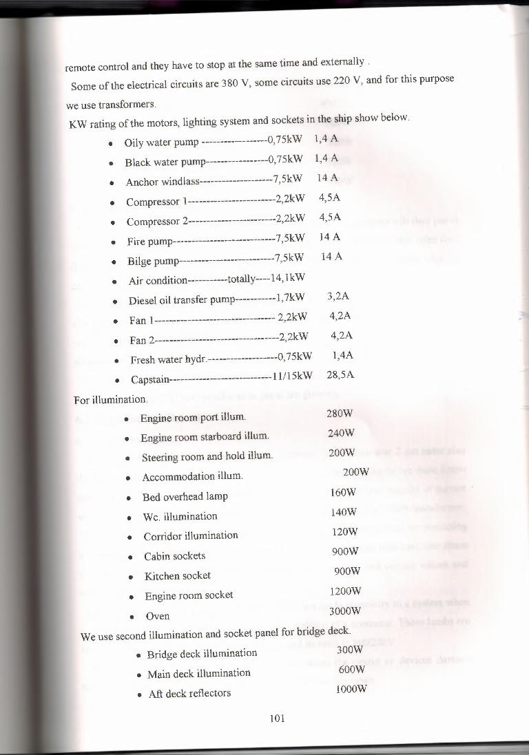
remote control and they have to stop at the same time and externally .
Some of the electrical circuits are 380 V, some circuits use 220 V, and for this purpose
we use transformers. KW rating of the motors, lighting system and sockets in the ship show below.
• Oily water pump ------------------0,75kW 1,4 A
• Black water pump-----------------0,75kW 1,4 A
• Anchor windlass-------------------- 7, SkW 14 A
• Compressor 1------------------------2,2kW 4,SA
• Compressor 2------------------------2,2kW 4,SA
• Fire pump----------------------------7,SkW 14 A
• Bilge pump--------------------------7,SkW 14 A
• Air condition-----------totally----14, lkW
• Diesel oil transfer pump-----------l,7kW 3,2A
• Fan 1--------------------------------- 2,2kW 4,2A
• Fan 2----------------------------------2,2kW 4,2A
• Fresh water hydr.-------------------0,75kW 1,4A
• Capstain----------------------------11/1 SkW 28,SA
For illumination.
• Engine room port ilium.
• Engine room starboard illum.
• Steering room and hold illum.
• Accommodation ilium.
• Bed overhead lamp
• W c. illumination
• Corridor illumination
• Cabin sockets
• Kitchen socket
• Engine room socket
280W
240W
200W
200W
160W
140W
120W
900W
900W
1200W
• Oven 3000W
We use second illumination and socket panel for bridge deck.
• Bridge deck illumination 300W
• Main deck illumination
• Aft deck reflectors
600W
1000W
101
• Frw. Deck reflectors
• Projector 1
• Projector 2
• Clear view screen
500W
2000W
IOOOW
300W
350W
720W
930W
• Wheel house illumination
• Nav. light reft. Supply
• Window wiper
6.6 Planning of Building
At first ship construction engineer is decide which kinds of equipments will they put in
to the ship according to ABS rules (ship type and ship dimension), from this rules they
find number of generators, capacity of pump and the other pumps, etc ... Some addition
can be including, for example air condition.
They send those data to the electric company. At the same time they must send the
ships plans to this company. Because they constitute the allocation plan. All the plans
must be harmony. For example pipe allocation plan, machinery allocation plan. If they
allocate their own equipment at the same place, they can cause some confusion.
When the electric company takes those datas, they can start to process. At first electric
plans are drawing, and than the allocation plans are drawing.
6. 7 Main Switch Board
6.7.1 Generator Part
We are produce electricity by generators. Generator 1 and generator 2 are same also
the circuit connections are exactly same. When we produce electricity we must know
the quantity of current, voltage, power, and frequency. We reduce the amount of current
when we measure, we use a current transformer for this job. It is 150/5 transformer.
Also we must read voltages of each phase , we must put a automatic fuse for protecting
a voltmeter selector switch. This device choose phase and they can read only one phase
voltage at the same time. KW meter is taking taking voltage and current values and
calculating power.
lMCB is the main contactor of generator 1. We can apply electricity to a system when
it is on position. lLl, 1L2 lambs are shows the position of a contactor. These lambs are
feed by 220V. It is supply by 1 T2 transformer and its ratio is 380/220V.
lBB is a busbar breaker. It is generally close when the circuit or devices damage
between lBB and generator 1 this is opened and devices are repair.
102
lKl controls the position of lambs (lLl and 1L2) and also we see it controls the
other parts U main contactor coil.
The second part is the same of the first generator part. The main think of this ships
electric system is every supply (Generator 1, Generator 2, and shore connection) worhs
alone; it means they can not use parallel connection.
At the end of this drawing we see 4TR transformer and a signal lamb, it show us is
there any voltage in busbar or not.
6. 7 .2 Distribution Part
When we analyze this plan they were use 13 motors, these are oily water pump, black
water pump, Anchor windlass, compressor 1 and compressor 2,fire pump, bilge pump,
air condition, diesel oil transfer pump,fanl,fan 2, fresh water hydrafore, capstain
windlass. Each one of them is control by 2 contacts, one of them is in the main switch
board and the other is near the device, the first one is using as afuse the second one is
using as on/off shalter.(The second switches are showing as Sin the box.)
6. 7 .3 Emergency Stop Remote Control
According to the ABS rules, some devices must be emergency stop externally. These
are air conditions, fans and diesel oil transfer pump. For example if there is a fire in a
room and air condition or fans flows air in a room and fire is grown. Same think is valid
for diesel oil transfer pump. Emergency stop button must be a different place from the
devices. Because fire may be near to these devices.
6. 7.4 Illumination
6.7.4.1 Transformer There is one more connection for illumination. We use a transformer for drop to
voltage ratio 380/220 V and its connection style delta-delta (6.-~). The advantage of this
connection is no phase shift associated with it and no problems with unbalanced load
harmonics.
6. 7 .4.2 Lighting Panel
There are 2 lighting panels. (Ll, L2) L 1 panel is control engine port illumination, engine room starboard illumination,
steering room and hold illumination, accommodation illumination, bed overhead lamb,
W c. illumination, corridor illumination, cabins sockets, kitchen sockets, engine room
sockets, oven and one more for spare. L2 panel is control bridge deck illumination, main deck illumination, aft deck
reflectors, Frw. Deck reflector, projector 1, projector 2, clear view screen, wheel house
103
illumination, nav. light reflector, window viper and one more spare.
For carrying cable one place to another place we use cable trays it is connecting
sealing or walls. While we spread cable on the trays we must agree with the rules. The
rules say that if a one tray has 10 cables, we can not put any more on it. We must spread
a new tray behind first one and it must have a 10 cm distance between two trays for air
circulation. Because cables can get warm when it is using.
When cables pass the steel wall if it is in below deck it must be water resistive. We
can get this condition with special equipment which is shown in figure 2.
6.8 Cost Analysis
At the end of the project I'm research the prize of the equipment which we are using
in the main switchboard end the other panels. They are only equipment prizes. All cost
of constructing this panels including worker's pay is nearly 25,000$. This prize levels
are taken from the GESAN Electric Company. They can not send us cable information,
only they can say that we are using MGG type of cable inside the panels, and MCGC
type of cable for lighting.
The equipment's prizes are shown in table 26, table 27, table 28, table 29 and table 30.
6.9 Calculations of Accumulator Batteries
All ships must use batteries for emergency conditions, while we are calculating the
magnitude of batteries; we have to know all emergency equipment's powers. We are
multiply by this value with quantity and we find total power. With using P=V*I we
can find all equipment's current's. We are multiplying this value with working time
demand factor we get the required A/h value. We are assuming the battery power fact
% 5 5. These calculations are shown in table 31.
104
CONCLUSION
One of the most important problem of the ship owner's is electrical problems,
when their ships are at the sailing. For decreasing those problems, the authorities have
been making investigations for long years. These investigations was occurred some
rules and all the ship electric firms have to attend them. These rules were improved for
sailing fewer problems and the most important thing for human safety. At nowadays
which the technology is improved so quickly, and the rules became more secure and
more comfortable.
Certainly one of the important reason is costs. If the number of the crews becomes
less, this is more economic for ship owners. Futures technology will give permeation to
create ships with minimum human been or without any human been.
This project was mentioned how to follow ship's electrical system from top to
end, the rules which must be attend and the necessary tests for equipment.
The sample ship's electrical system is AC, also for emergency conditions there is
a 24V DC circuit. At this ship there are two caterpillar generators. Each generator is 74
KVA and 3-phase 380V. These are connected to busbar after measuring their voltage,
current, frequency, and kilowatt ratings. From the busbar, it is distributed to the
necessary equipments like; pumps, fans, air condition and lighting circuits.
The important thing which always have to be remembered, the cables is become
hot when the current flows inside from it. For this purpose all the cables could not
spread at the same point, there must be a space between them for feeder cables, but not
for lighting circuit, because lighting circuits needs fewer power.
Ship electric technology is very convenient to improve. The contactors can be
easily control by PLC. Of course the inputs and the outputs must be modificated for
large current. Later the navigation systems can be adapted to the PLC and ships will
control without human. But totally humanless ships are only dream, because when the
system is failure some ones must be repair them.
105
REFERENCES
[l] ABS booklet for Electrical Engineers
(Rules for building and classing (STEEL VESSELS 2001))
[2] ABS home page http://www.eagle.org
[3] For electrical equipments http://www.schneider-electric.com.tr
106
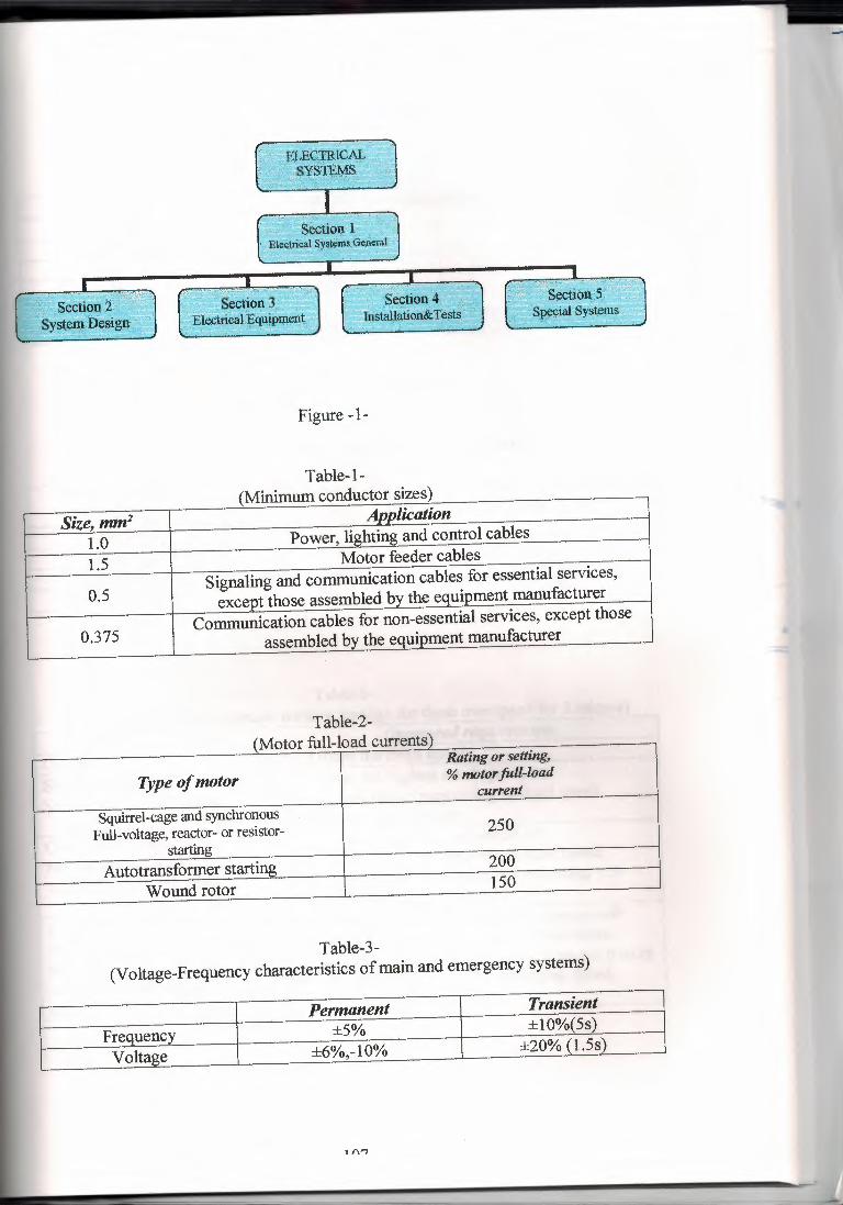
Figure -1-
Size, mm2 Aootication
1.0 Power, lighting and control cables
1.5 Motor feeder cables
0.5 Signaling and communication cables for essential services, except those assembled by the equipment manufacturer
0.375 Communication cables for non-essential services, except those
assembled by the equipment manufacturer
Table-1- {Minimum conductor sizes)
Table-2- llV101Ur 1u11-1uau ~uin,iu..:>J
Rating or setting,
Type of motor % motor fidl-load current
Squirrel-cage and synchronous Full-voltage, reactor- or resistor- 250
starting Autotransformer starting 200
Wound rotor 150
Table-3- (Voltage-Frequency characteristics of main and emergency systems)
Permanent Transient
Frequency ±5% ±10%(5s)
Voltage ±6%,-10% ±20% (1.5s)
1 f\"7
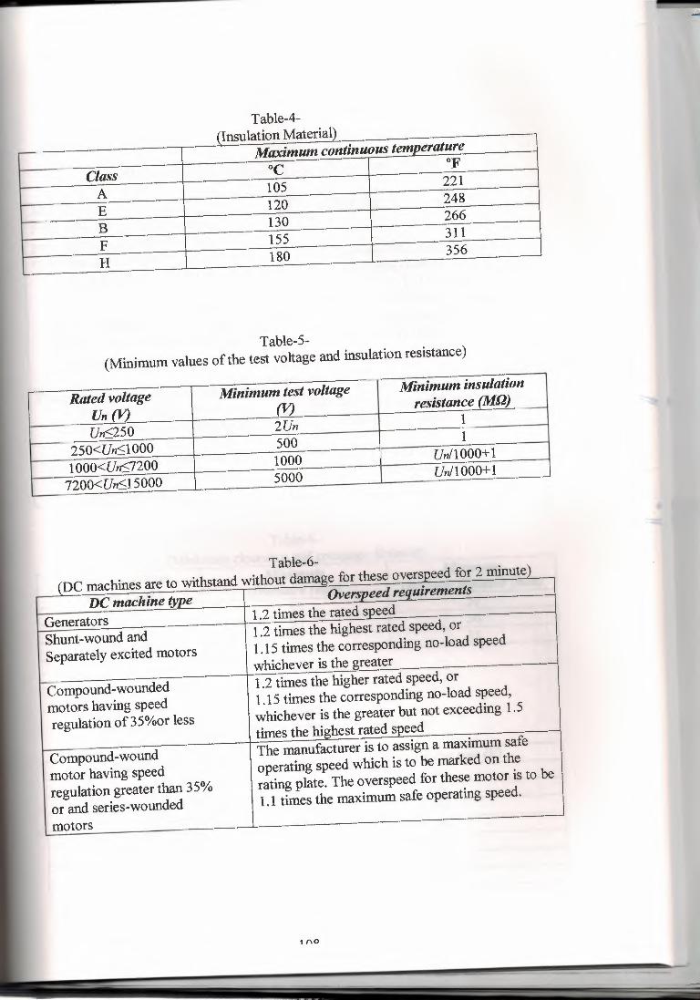
Table-4- (Insulation Matena11
Maximum continuous temperature
Class oc OF
A 105 221
E 120 248
B 130 266
F 155 311
H 180 356
Table-5- (Minimum values of the test voltage and insulation resistance)
Rated voltage Un (J1
Minimum test voltage (V)
Minimum insulation resistance (M_!JJ
Un~250 2Un 1
250<Un~l 000 500 1
1 ooo<Un~7200 1000 Un/1000+1
7200<Un~l 5000 5000 Un/1000+1
Table-6- _(DC machines are to withstand without damage for these overspeed for 2 minute) '---
DC machine type Overspeed requirements
Generators 1.2 times the rated speed
Shunt-wound and 1.2 times the highest rated speed, or
Separately excited motors 1.15 times the corresponding no-load speed whichever is the greater
Compound-wounded 1.2 times the higher rated speed, or
motors having speed 1.15 times the corresponding no-load speed,
regulation of35%or less whichever is the greater but not exceeding 1.5 times the highest rated speed
Compound-wound The manufacturer is to assign a maximum safe
motor having speed operating speed which is to be marked on the
regulation greater than 35% rating plate. The overspeed for these motor is to be
or and series-wounded 1.1 times the maximum safe operating speed.
motors
1 (\0
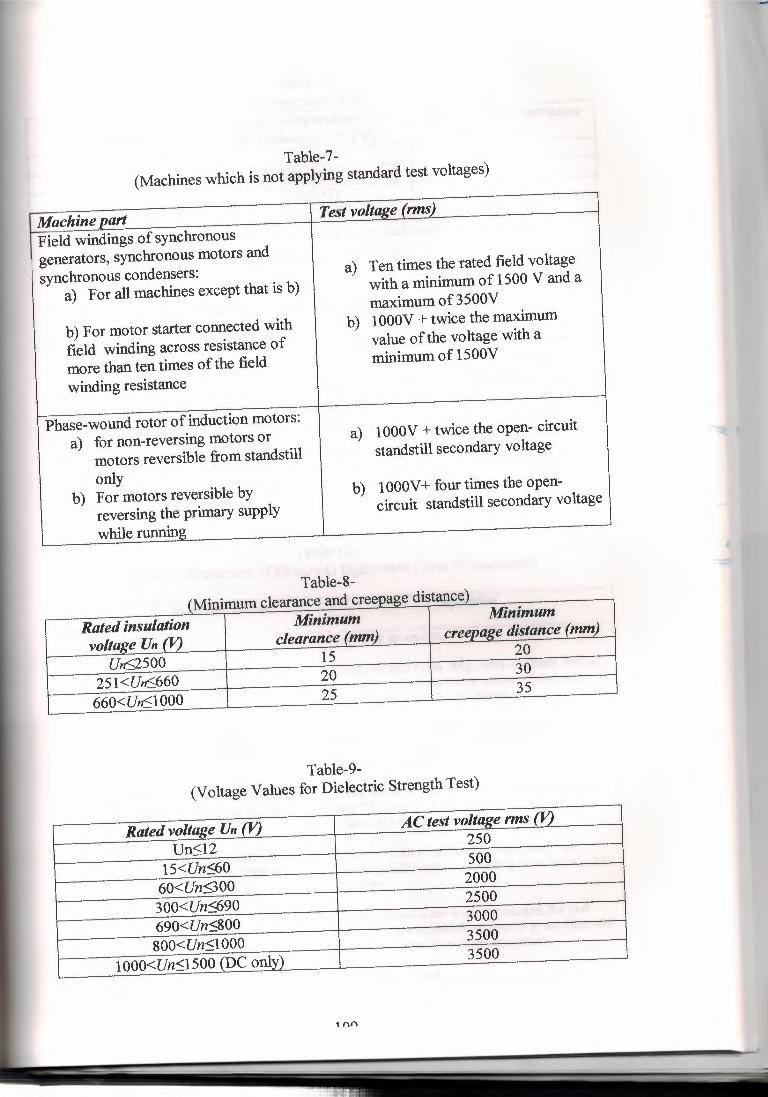
Machine part Test voltage (rms)
Field windings of synchronous generators, synchronous motors and synchronous condensers:
a) Ten times the rated field voltage
a) For all machines except that is b) with a minimum of 1500 V and a maximum of 3500V
b) For motor starter connected with b) 1 OOOV + twice the maximum
field winding across resistance of value of the voltage with a
more than ten times of the field minimum of 1500V
winding resistance
Phase-wound rotor of induction motors: a) for non-reversing motors or a) lOOOV + twice the open- circuit
motors reversible from standstill standstill secondary voltage
only b) For motors reversible by b) lOOOV+ four times the open-
reversing the primary supply circuit standstill secondary voltage
while running
Table-7- (Machines which is not applying standard test voltages)
.•...••. .a..... ••. ------ - _. .••. -- •.... ~-
Rated insulation Minimum Minimum
voltage Un (V,) clearance (mm) creeoaee distance (mm)
Un<2500 15 20
251 <U,6660 20 30
660<Un<l 000 25 35
{M'. 1, Table-8-
d d' l
Table-9- (Voltage Values for Dielectric Strength Test)
Rated voltaee Un (V,) AC test voltage rms (V,)
Un<l2 250
15<Un<60 500
60<Un900 2000
300<Un<690 2500
690<Un<800 3000
&OO<Un<l 000 3500
lOOO<Un<l500 (DC onlv) 3500
1 '"'
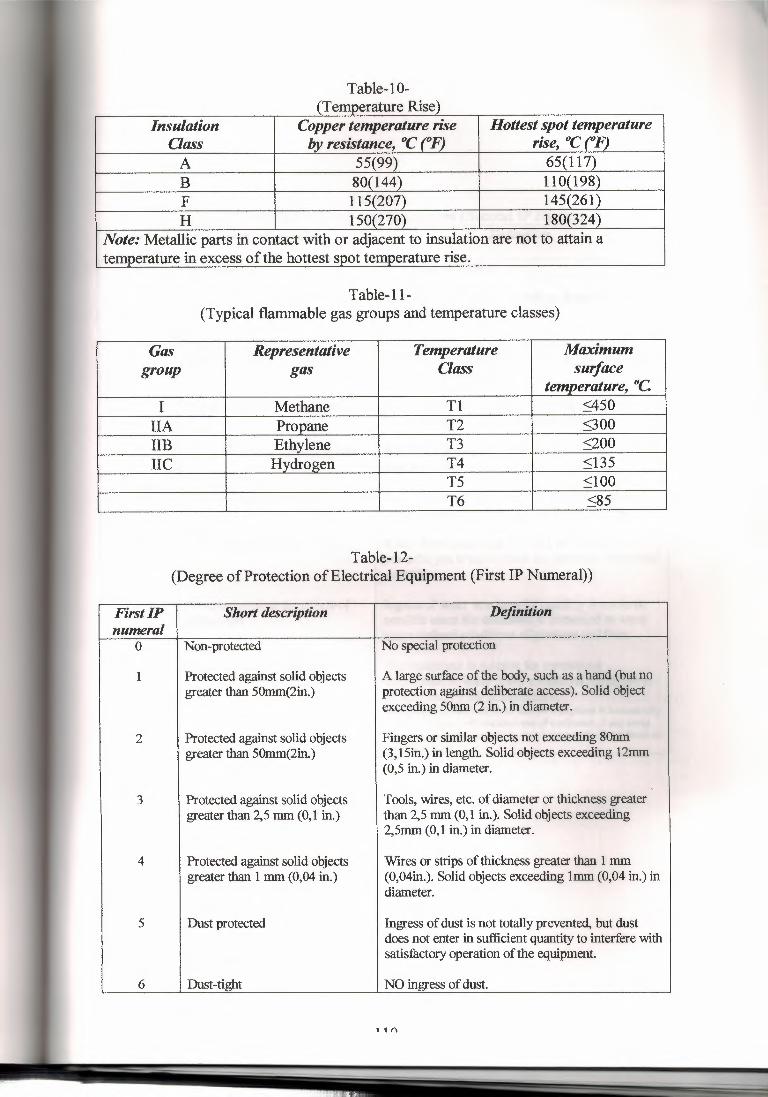
Table-10- {Temper~ture Rise)
Insulation Copper temperature rise JloUestspottemperature Oass by resistance, °C (0F) rise, °C (°F) A 55(99) 65(117) B 80(144) 110(198) F 115(207) 145(261) H 150(270) 180(324)
Note: Metallic parts in contact with or adjacent to insulation are not to attain a temperature in excess of the hottest spot temperature rise.
Table-11- (Typical flammable gas groups and temperature classes)
Gas Representative Temperature Maximum group gas Class surface
temperature, °C I Methane Tl <450
IIA Propane T2 <300 IIB Ethylene T3 <200 IIC Hydrogen T4 <135
TS :Sl 00 T6 :S85
Table-12- (Degree of Protection of Electrical Equipment (First IP Numeral))
First IP Short description Definition numeral
0 Non-protected No special protection
1 Protected against solid objects A large surface of the body, such as a hand (but no greater than 50mm(2in.) protection against deliberate access). Solid object
exceeding 50nm (2 in.) in diameter.
2 Protected against solid objects Fingers or similar objects not exceeding 80nm greater than 50mm(2in.) (3,15in.) in length. Solid objects exceeding 12mm
(0,5 in.) in diameter.
3 Protected against solid objects Tools, wires, etc. of diameter or thickness greater greater than 2,5 mm (0, 1 in.) than 2,5 mm (0,1 in.). Solid objects exceeding
2,5mm (0,1 in.) in diameter.
4 Protected against solid objects Wires or strips of thickness greater than 1 mm greater than 1 mm (0,04 in.) (0,04in.). Solid objects exceeding Imm (0,04 in.) in
diameter.
5 Dust protected Ingress of dust is not totally prevented, but dust does not enter in sufficient quantity to interfere with satisfactory operation of the equipment.
6 Dust-tight NO ingress of dust.
1 1 f\
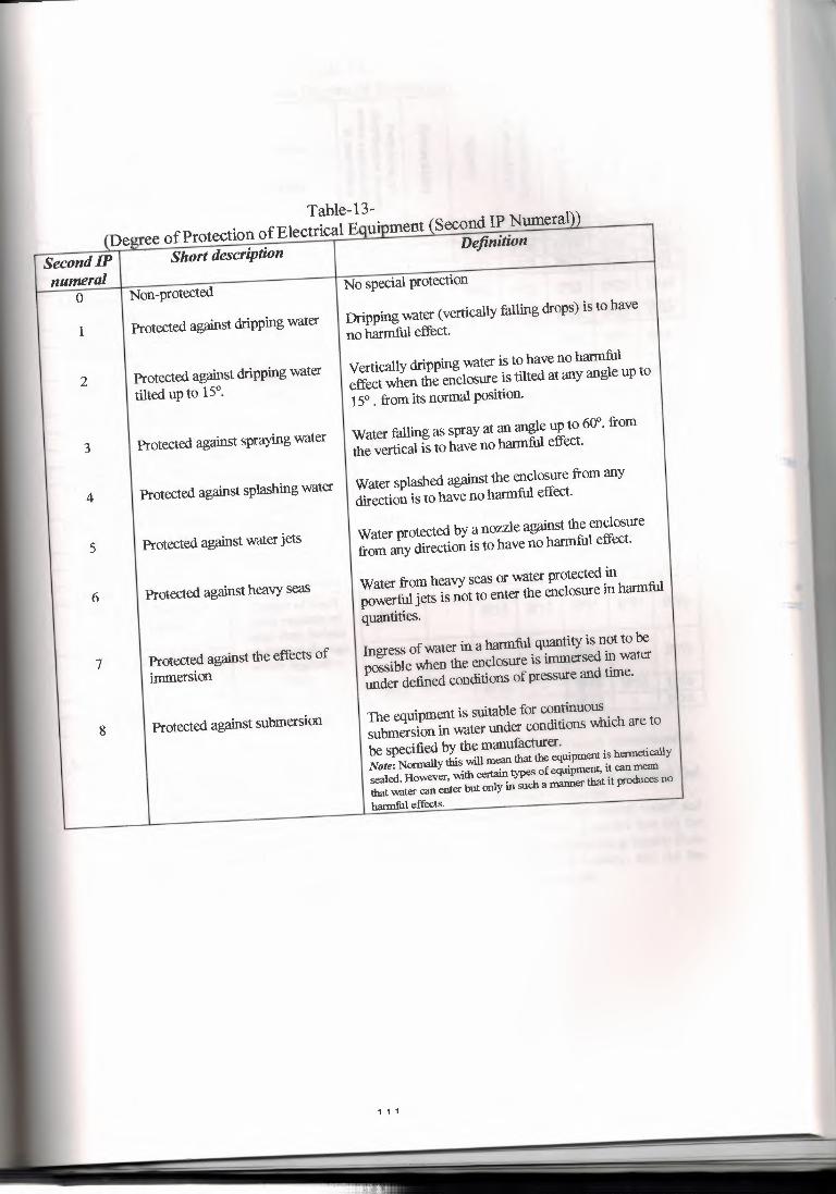
Table-13- {Degree of Protection of Electrical Equipment{Second IP Numeral))
Second IP I Short description I Definition
numeral Non-protected
No special protection 0
1 Protected against dripping water
2 Protected against dripping water tilted up to 15°.
3 Protected against spraying water
4 Protected against splashing water
5 Protected against water jets
6 Protected against heavy seas
7 Protected against the effects of immersion
8 Protected against submersion
Dripping water (vertically falling drops) is to have no harmful effect.
Vertically dripping water is to have no harmful effect when the enclosure is tilted at any angle up to 15° . from its normal position.
Water falling as spray at an angle up to 60°. from the vertical is to have no harmful effect.
Water splashed against the enclosure from any direction is to have no harmful effect.
Water protected by a nozzle against the enclosure from any direction is to have no harmful effect.
Water from heavy seas or water protected in powerful jets is not to enter the enclosure in harmful quantities.
Ingress of water in a harmful quantity is not to be possible when the enclosure is immersed in water under defined conditions of pressure and time.
The equipment is suitable for continuous submersion in water under conditions which are to be specified by the manufacturer. Note: Normally this will mean that the equipment is hermetically sealed. However, with certain types of equipment, it can mean that water can enter but only in such a manner that it produces no
harmful effects.
1 1 1
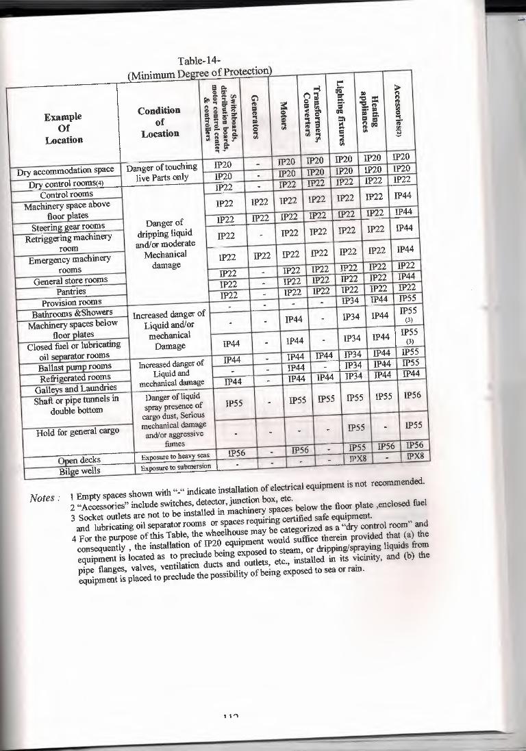
Table-14- (Minimum Degree of Protection)
e =- ~ t"" Qi,;· -· ~ R-lS.f ~ ~"1 iJCI 11D 1:1"
Example Condition •••••• Cl' = fl> ~ e 11D :::. 'C = n
e ea ... = = ~ = 'i. " " of
a. a. !" :r' " a ~ S' iJCI •• IID ~
Of ..•..• = g' "1 ~~ Q
&a,~ 11D ~
:l. "1 ::a "1
Location Location s " e i n = ;· $8•=- "1 l ~
" iJCI ~ ti.I
ti.I
= ..• !" !fl "1 ~ ;: e, " ..• - ti.I
Dry accommodation space Danger of touching IP20 - IP20 IP20 IP20 IP20 IP20
Dry control roomS(4) live Parts only JP20 . IP20 IP20 IP20 IP20 IP20
Control rooms IP22 . IP22 IP22 IP22 IP22 IP22
Machinery space above IP22 IP22 IP22 IP22 IP22 IP22 IP44
floor plates Steering gear rooms Danger of IP22 IP22 IP22 IP22 IP22 IP22 IP44
Retriggering machinery dripping liquid IP22 - IP22 IP22 IP22 IP22 IP44
room and/or moderate
Emergency machinery Mechanical IP22 IP22 IP22 IP22 IP22 IP22 IP44
rooms damage
General store rooms IP22 - IP22 IP22 IP22 IP22 IP22
Pantries IP22 - IP22 IP22 IP22 IP22 IP44
Provision rooms IP22 - IP22 IP22 IP22 IP22 IP22
Bathrooms &Showers Increased danger of - - - - IP34 IP44 IP55
Machinery spaces below Liquid and/or - - IP44 - IP34 IP44 IP55
floor plates mechanical
(3)
Closed fuel or lubricating Damage IP44 - IP44 - IP34 IP44 IP55
oil separator rooms
(3)
Ballast pump rooms Increased danger of IP44 - IP44 IP44 IP34 IP44 IPS5
Refrigerated rooms Liquid and - - IP44 - IP34 IP44 IP55
Galleys and Laundries mechanical damage IP44 - IP44 IP44 IP34 IP44 IP44
Shaft or pipe tunnels in Danger ofliquid double bottom spray presence of IP55 - IP55 IP55 IP55 IP55 IP56
cargo dust, Serious
Hold for general cargo mechanical damage and/or aggressive - - - - IP55 - IP55
fumes
Open decks Exposure to heavy seas IP56 - IP56 - IP55 IP56 IP56
Bilee wells Exposure to submersion - - . - IPX8 - IPX8
Notes : 1 Empty spaces shown with"·" indicate installation of electrical equipment is not recommended. 2 "Accessories" include switches, detector,junction box, etc. 3 Socket outlets are not to be installed in machinery spaces below the floor plate ,enclosed fuel and lubricating oil separator rooms or spaces requiring certified safe equipment. 4 For the purpose of this Table, the wheelhouse may be categorized as a "dry control room" and consequently , the installation of IP20 equipment would suffice therein provided that (a) the equipment is located as to preclude being exposed to steam, or dripping/spraying liquids from pipe flanges, valves, ventilation ducts and outlets, etc., installed in its vicinity, and (b) the equipment is placed to preclude the possibility of being exposed to sea or rain.
1 1 ,i
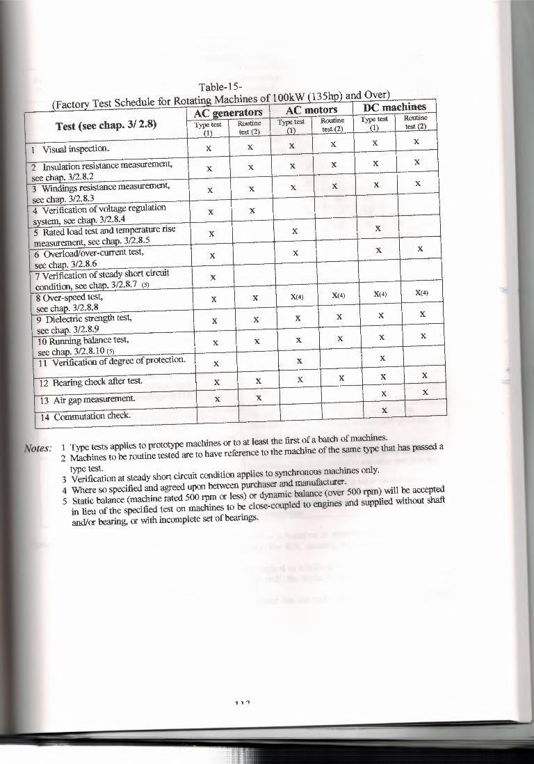
Table-15- (Factorv Test Schedule for Rotatmg Macmnes or 1 vv1'. n , • .,., •• ., -··- . - -
AC generators AC motors DC machines Test (see chap. 3/ 2.8) Type test Routine Type test Routine Type test Routine
(1) test (2) (1) test (2) (1) test (2)
1 Visual inspection. X X X X X X
2 Insulation resistance measurement, X X X X X X
see chap. 3/2.8.2 3 Windings resistance measurement, X X X X X X
see chap. 3/2.8.3 4 Verification of voltage regulation X X system, see chap. 3/2.8.4 5 Rated load test and temperature rise X X X
measurement, see chap. 3/2.8.5 6 Overload/over-current test, X X X X
see chap. 3/2.8.6 7 Verification of steady short circuit X condition, see chap. 3/2.8.7 (3) 8 Over-speed test, X X X(4) X(4) X(4) X(4)
see chap. 3/2.8.8 9 Dielectric strength test, X X X X X X
see chap. 3/2.8.9 10 Running balance test, X X X X X X
see chap. 3/2.8.10 (S) 11 Verification of degree of protection. X X X
12 Bearing check after test. X X X X X X
13 Air gap measurement. X X X X
14 Commutation check. X
Notes: 1 Type tests applies to prototype machines or to at least the first of a batch of machines. 2 Machines to be routine tested are to have reference to the machine of the same type that has passed a type test. 3 Verification at steady short circuit condition applies to synchronous machines only.
4 Where so specified and agreed upon between purchaser and manufacturer. 5 Static balance (machine rated 500 rpm or less) or dynamic balance (over 500 rpm) will be accepted in lieu of the specified test on machines to be close-coupled to engines and supplied without shaft and/or bearing, or with incomplete set ofbearings.
1 1 'l
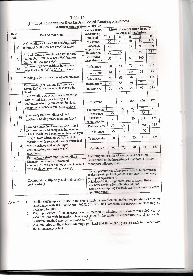
...__ - -- -- ~ (1)
Item Temperature Limit of temperature fuse, °C
No. Part of machine measuring For class of insulation
method A E B F H
A.C windings of machines having rated Resistance 50 - 70 90 115
a) output of5,000 kW (or kV A) or more Embedded 55 - 75 95 120 temp. detector
A.C windings of machines having rated Resistance 50 65 70 95 115
1 b) output above 200 kW (or kVA) but less Embedded than 5,000 kW (or kVA) temp. detector 55 - 80 100 120
c) A.C windings of machines having rated Resistance 50 65 70 95 115 outputs of200 kW (or kVA) or less c2)
Thermometer 40 55 60 75 95
2 Windings of armatures having commutators Resistance 50 65 70 95 115
Field windings of AC and D.C machines Thermometer 40 55 60 75 95
3 having D.C excitation, other than those in Resistance 50 65 70 95 115 item4 Field winding of synchronous machines
a) with cylindrical rotor having D.C excitation winding embedded in slots, Resistance - - 80 100 125
excent synchronous induction motors Thermometer 40 55 60 75 95
b) Stationary field windings of A.C Resistance 50 65 70 95 115
machines having more than one layer Embedded temo, detector - - 80 100 125
4 Low resistance field winding of A.C and Thermometer 50 65 70 90 115
c) D.C machines and compensating windings 50 ofD.C machines having more than one layer Resistance 65 70 90 115
Single-layer windings of A.C and D.C Thermometer 50 70 80 100 125 machines with exposed bare or varnished
d) metal surfaces and single layer compensating windings ofD.C Resistance 50 70 80 100 125
machines» 5 Permanently short-circuited windings The temperature rise of any parts is not to be
Magnetic cores and all structural detrimental to the insulating of that part or to any
6 components, whether or not in direct contact other part adjacent to it. with insulation ( excluding bearings) The temperature rise of any parts is not to be detrimental
to the insulating of that part or to any other part or to any
Commutators, slip-rings and their brushes other part adjacent to it
7 and brushing Additionally, the terq,eraiure is not to exceed that at which the combination of brush grade and commutators/slip-ring materials can handle over the entire ,.~. range.
Table-16- (Limit of Temperature Rise for Air Cooled Rotating Machines)
Amblent tf'mnerature = 50°C
Notes: 1 The limit of temperature rise in the above Table is based on an ambient temperature of 50°C in accordance with IEC Publication 60092-101. For 40°C ambient, the temperature rises may be increased by 10°C.
2 With application of the superposition test method to windings of machines rated 200 kW (or kVA) or less with insulation classes A,E,B or F, the limits of temperature rise given for the resistance method may be increased by 5°C.
3 Also includes multiple layer windings provided that the under layers are each in contact with the circulating coolant.
1 1 A
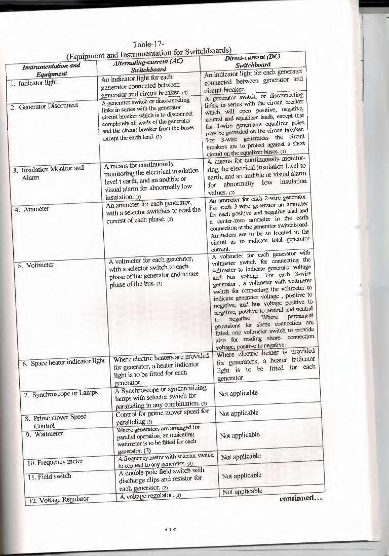
Table-17- (Euuioment and Instrumentation tor :,wn:cnuua.Lu.,,,
Instrumentation and Alternating-cullent (AC) Direct-cullent (DC)
Eauipment Switchboard Switchboard
1. Indicator light An indicator light for each
An indicator light for each generator
generator connected between connected between generator and
generator and circuit breaker. (3) circuit breaker.
2. Generator Disconnect A generator switch or disconnecting
A generator switch, or disconnecting
links in series with the generator links, in series with the circuit breaker
circuit breaker which is to disconnect which will open positive, negative,
completely all leads of the generator neutral and equalizer leads, except that
and the circuit breaker from the buses for 3-wire generators equalizer poles
except the earth lead. (1) may be provided on the circuit breaker. For 3-wire generators the circuit breakers are to protect against a short circuit on the eoualizer buses. (1)
3. Insulation Monitor and A means for continuously A means for continuously monitor-
Alarm monitoring the electrical insulation
ring the electrical insulation level to
level t earth. and an audible or earth, and an audible or visual alarm
visual alarm for abnormally low for abnormally low insulation
insulation. (3) values. (3)
4. Ammeter An ammeter for each generator,
An ammeter for each 2-wire generator.
with a selector switches to read the For each 3-wire generator an ammeter
current of each phase. (3) for each positive and negative lead and a center-zero ammeter in the earth connection at the generator switchboard. Annneters are to be so located in the circuit as to indicate total generator current.
5. Voltmeter A voltmeter for each generator,
A voltmeter for each generator with
with a selector switch to each voltmeter switch for connecting the
phase of the generator and to one voltmeter to indicate generator voltage
phase of the bus. (3) and bus voltage. For each 3-wire generator , a voltmeter with voltmeter switch for connecting the voltmeter to indicate generator voltage , positive to negative, and bus voltage positive to negative, positive to neutral and neutral to negative. Where pennanent provisions for shore connection are fitted, one voltmeter switch to provide also for reading shore- connection voltage, oositive to ne!!fttive
6. Space heater indicator light Where electric heaters are provided Where electric heater is provided
for generator, a heater indicator for generators, a heater indicator
light is to be fitted for each light is to be fitted for each
generator. generator.
7. SynchroscopeorLamps A Synchroscope or synchronizing lamps with selector switch for Not applicable
paralleling in any combination. (3)
8. Prime mover Speed Control for prime mover speed for Not applicable
Control paralleling (3)
9. Wattmeter Where generators are arranged for parallel operation, an indicating Not applicable wattmeter is to be fitted for each generator. (3)
10. Frequency meter A frequency meter with selector switch Not applicable to connect to anv generator. (3)
11. Field switch A double-pole field switch with discharge clips and resistor for Not applicable
each generator. (2)
12. Voltage Regulator A voltage regulator. (3) Not applicable continued ...
1 1 t:
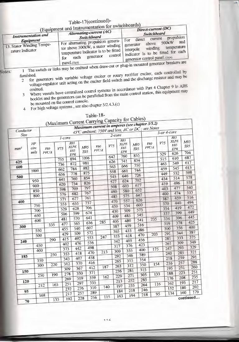
\cQu1µu..1vu• -~- --- _ 1entat1on for sw1tchooarus J
Instrumentation and Altemating-cu"ent (AC)
Direct-cu"ent (DC)
Eauipment Switchboard
Switchboard
13. Stator Wmding Tempe- For alternating propulsion genera- For direct current propulsion
rature Indicator tor above 500kW, a stator winding generator above 500kW and
temperature indicator is to be fitted interpole winding temperature
for each generator control indicator is to be fitted for each
panel.(3)( 4) generator control P3D:el. (3X4)
Table-17( continued)-
. totes: 1 The switch or links may be omitted when draw-out or plug-in mounted generator breakers are
furnished. 2 for generators with variable voltage exciter or rotary rectifier exciter, each controlled by voltage-regulator unit acting on the exciter field switch and the discharge resistor and may be
omitted. 3 Where vessels have centralized control systems in accordance with Part 4 Chapter 9 in ABS booklet and the generators can be paralleled from the main control station, this equipment may
be mounted on the control console. 4 For high voltage systems, see also chapter 5/2.4.3.(c)
------- - -~ --· • _J - ""I-'---- •..
Conductor Maximum cu"ent in amperes (see chapter 3/5.2)
Size 45°C ambient; 750V and less, AC or DC; see Notes
I-core 2-core
3-or 4-core
1()3 R85 R85
R85
mm2 circ V60 V75 XLPE M95 V60 V75 XLPE M95 V60 V75 XLPE M95
mils PVO'A F,85 S95 PVO'A F,85 S95 PVC/A
F,85 S95
EPR EPR
EPR
625 755 894 1006 642 760 855 529 626 704
600 736 872 981 626 741 834 515 610 687
1()00 662 784 882 563 666 750 463 549 617
500 656 778 875 558 661 744 459 545 613
950 641 760 854 545 646 726 449 532 598
900 620 734 826 527 624 702 434 514 578
850 598 709 797 508 603 677 419 496 558
800 576 682 767 490 580 652 403 477 540
400 571 677 761 485 575 647 400 474 533
750 553 655 737 470 557 626 387 459 516
700 529 628 706 450 534 600 370 440 494
650 506 599 674 430 509 573 354 419 472
600 481 570 641 409 485 545 337 399 449
300 335 477 565 636 285 405 480 541 235 334 396 445
550 455 540 607 387 459 516 319 378 425
500 429 509 572 365 433 486 300 356 400
240 290 415 492 553 247 353 418 470 203 291 344 387
450 402 476 536 342 405 456 281 333 375
400 373 442 498 317 376 423 261 309 349
185 250 353 418 470 213 300 355 400 175 247 293 329
350 343 407 458 292 346 389 240 285 321
300 220 312 370 416 265 315 354 218 259 291
150 309 367 412 187 263 312 350 154 216 257 288
250 190 278 330 371 236 281 315 195 231 260
120 269 319 359 162 229 271 305 133 188 223 251
212 165 251 297 335 213 252 285 176 208 235
95 232 276 310 140 197 235 264 116 162 193 217
168 217 257 289 184 218 246 152 180 202
70 135 192 228 256 115 163 194 218 95 134 160 179
{M C Table-l8- C::1rrving C for Cable~
continued ...
1 1 C.
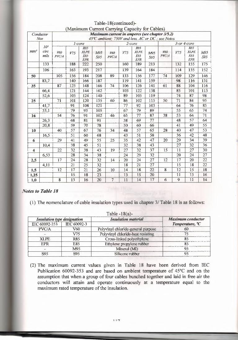
Table-18( continued)-
Conductor Maximum current in amperes (see chapter 3/5.2) Size 45°C ambient; 750V and less, AC or EC; see Notes
I-core 2-core 3-or 4-core ]03 R85 R85 R85
mm2 circ V60 V75 XLPE M95 V60 V75 XLPE M95 V60 V75 XLPE M95 mils PVC/A E85 S95 PVC/A E85 S95 PVC/A E85 S95
EPR EPR EPR 133 188 222 250 160 189 213 132 155 175 106 163 193 217 139 164 184 114 135 152
50 105 156 184 208 89 133 156 177 74 109 129 146 83,7 140 166 187 119 141 159 98 116 131
35 87 125 148 166 74 106 126 141 61 88 104 116 66,4 121 144 162 103 122 138 85 101 113 52,6 105 124 140 89 105 119 74 87 98
25 71 101 120 135 60 86 102 115 50 71 84 95 41,7 91 108 121 77 92 103 64 76 85 33,1 79 93 105 67 79 89 55 65 74
16 54 76 91 102 46 65 77 87 38 53 64 71 26,3 68 81 91 58 69 77 48 57 64 20,8 59 70 78 50 60 66 41 49 55
10 40 57 67 76 34 48 57 65 28 40 47 53 16,5 51 60 68 43 51 58 36 42 48
6 29 41 49 55 25 35 42 47 20 29 34 39 10,4 38 45 51 32 38 43 27 32 36
4 22 32 38 43 19 27 32 37 15 11 27 30 6,53 28 34 38 24 29 32 20 24 27
2,5 17 24 28 32 14 20 24 27 12 17 20 22 4,11 21 25 32 18 21 27 15 18 22
1,5 12 17 21 26 IO 14 18 22 8 12 15 18 1,25 15 18 23 13 15 20 11 13 16 1,0 8 13 16 20 7 11 14 17 6 9 11 14
Notes to Table 18
(1) The nomenclature of cable insulation types used in chapter 3/ Table 18 is as follows:
Table -18{<.l}- ' -
Insulation type designation Insulation material Maximum conductor IEC 60092-353 IEC60092-3 Temperature, °C
PVC/A V60 Polyvinyl chloride-general purpose 60 - V75 Polyvinyl chloride-heat resisting 75
XLPE R85 Cross-linked polyethylene 85 EPR E85 Ethylene propylene rubber 85 - M95 Mineral (MI) 95
S95 S95 Silicone rubber 95
(2) The maximum current values given in Table 18 have been derived from IEC Publication 60092-353 and are based on ambient temperature of 45°C and on the assumption that when a group of four cables bunched together and laid in free air the conductors will attain and operate continuously at a temperature equal to the maximum rated temperature of the insulation.
1 1 "7
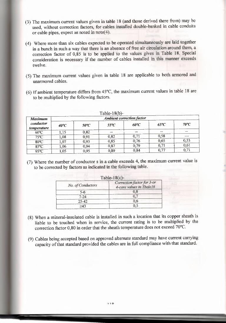
(3) The maximum current values given in table 18 (and those derived there from) may be used, without correction factors, for cables installed double-banked in cable conduits or cable pipes, expect as noted in note( 4).
(4) Where more than six cables expected to be operated simultaneously are laid together in a bunch in such a way that there is an absence of free air circulation around them, a correction factor of 0,85 is to be applied to the values gives in Table 18. Special consideration is necessary if the number of cables installed in this manner exceeds twelve.
(5) The maximum current values given in table 18 are applicable to both armored and unarmored cables.
( 6) If ambient temperature differs from 45°C, the maximum current values in table 18 are to be multiplied by the following factors.
----- --,-,, Maxi11111m Ambient correction factor conductor 40°c 50°C src 60°C 65°C 70°c temperature
60°C 1,15 0,82 -- -- -- -- 15°c 1,08 0,91 0,82 0,71 0,58 --- 80°C 1,07 0,93 0,85 0,76 0,65 0,53 85°C 1,06 0,94 0,87 0,79 0,71 0,61 95°c 1,05 0,95 0,89 0,84 0,77 0,71
(7) Where the number of conductor s in a cable exceeds 4, the maximum current value is to be corrected by factors as indicated in the following table.
,
No. of Conductors Correction factor for 3-or 4-core values in Tbalel8
5-6 0,8 7-24 0,7 25-42 0,6 >43 0,5
(8) When a mineral-insulated cable is installed in such a location that its copper sheath is liable to be touched when in service, the current rating is to be multiplied by the correction factor 0,80 in order that the sheath temperature does not exceed 70°C.
(9) Cables being accepted based on approved alternate standard may have current carrying capacity of that standard provided the cables are in full compliance with that standard.
1 1 0
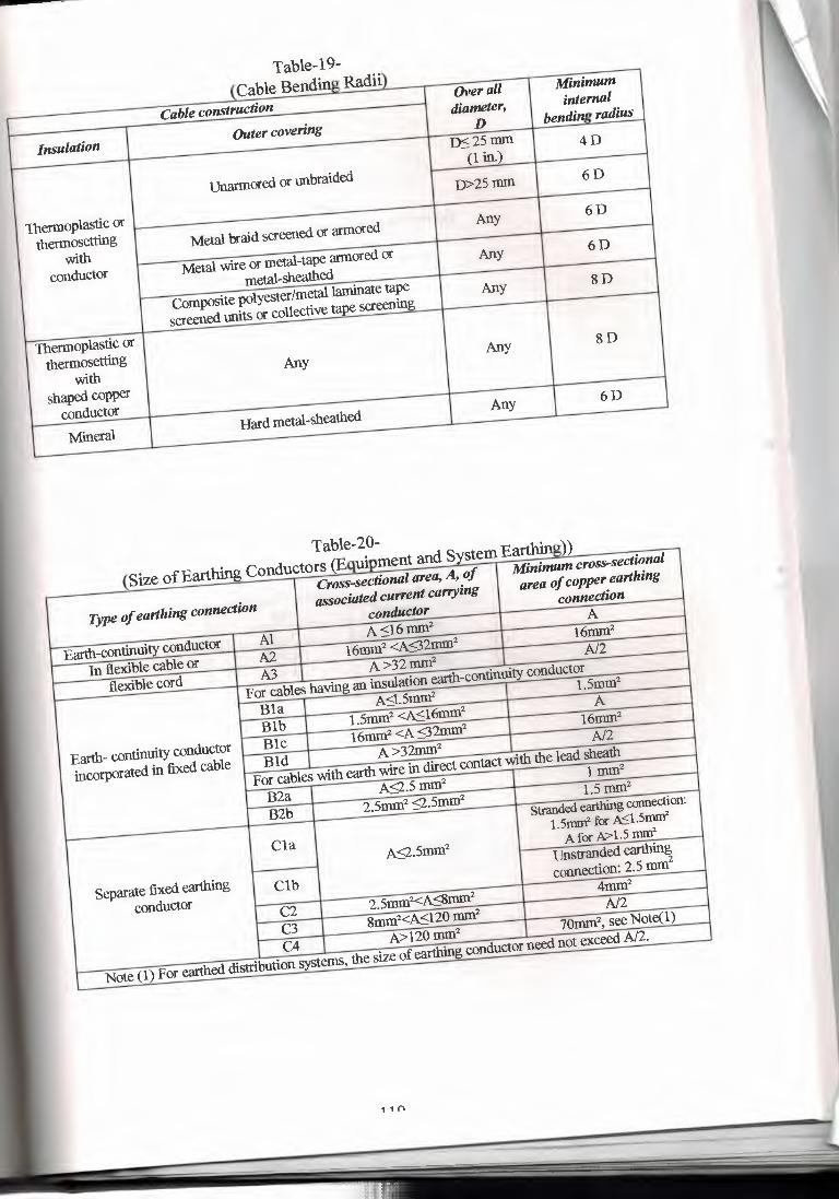
l vav•v ----- u Radii)
Cable construction Overall Minimum
Insulation Outer covering
diameter, internal
D bendinl! radius
~25mm 4D
unarmored or unbraided
(1 in.)
D>25tnm 6D
Thermoplastic or thermosetting Metal braid screened or armored
Any 6D
with conductor
Metal wire or metal-tape armored or Any 6D
metal-sheathed Composite polyester/metal laminate tape Any 8D
screened units or collective tape screening
Thermoplastic or thermosetting
with Any
Any 8D
shaped copper conductor Mineral
Hard metal-sheathed Any 6D
Table-19-
-- - - -- - ,q uHh••---- - J~--
Cross-sectional area, A, of Minimum cross-sectional
Type of earthing connection associated current carrying
area of copper earthing
conductor connection
Earth-continuity conductor Al
A <16tnm2
A
In flexible cable or A2
16tnm2 <A<32tnm2
16mrn2
flexible cord A3 A>32mm2
A/2
For cables having an msulation earth-continuity conductor
Bla A<l.5mm2
L5mm2
Blb l.5mm2 <A<l6tnm2
A
Earth- continuity conductor Blc
16tnm2 <A <32mm2 16mm2
incorporate4 in fixed cable Bld A>32tnm2
A/2
For cables with earth wire in direct contact with the lead sheath
B2a A<2.5 mrn2
l mm2
B2b 2.smrn2 <2.5mm2
1.5 mrn2 Stranded earthing connection:
Cla
1.smnr for ~1.smnr
A9.5rorn2
A for A> 1.5 nn:n2
Separate fixed earthing Clb
Unstranded earthing
conductor
connection: 2.5 mm'
C2 2.5mm2<A<8mm2
4rom2
C3 stnm2<A<120 mrn2
A/2
C4 A>12omrn2
70mm2, see Note(l)
Note (I) For earthed distribution systems, the size of earthing co,ductor need not exceed A/2.
(S' fEarthinl! Cond
Table-20- (E dS Earthing))
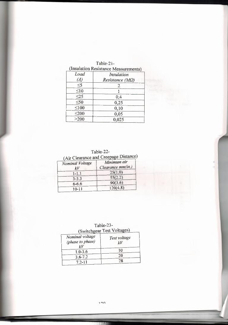
Table-21- (In~ulation Resistance Measurements 2 -
Load Insulation (A) Resistance (MQ) ~5 2 ~10 1 ~25 0,4 <50 0,25 <100 0,10 <200 0,05 >200 0,025
Table-22- Air Clearance and Creepage Distance)
- -- • 1 Minimum air I Clearance mm(inJ
Nominal Voltage kV 1-1.1 25(1.0 3-3.3 55£2.2_} 6-6.6 90{3.~ 10-11 120{4.8)
Table-23- \ 0 VV 1.\.\,,,/1.i~"'u..i. ...._ _........ •
___ .. _ Nominal voltage Test voltage (phase to phase) kV
kV 1.0-3.6 10 3.6-7.2 20 7.2-11 28
1 "(\
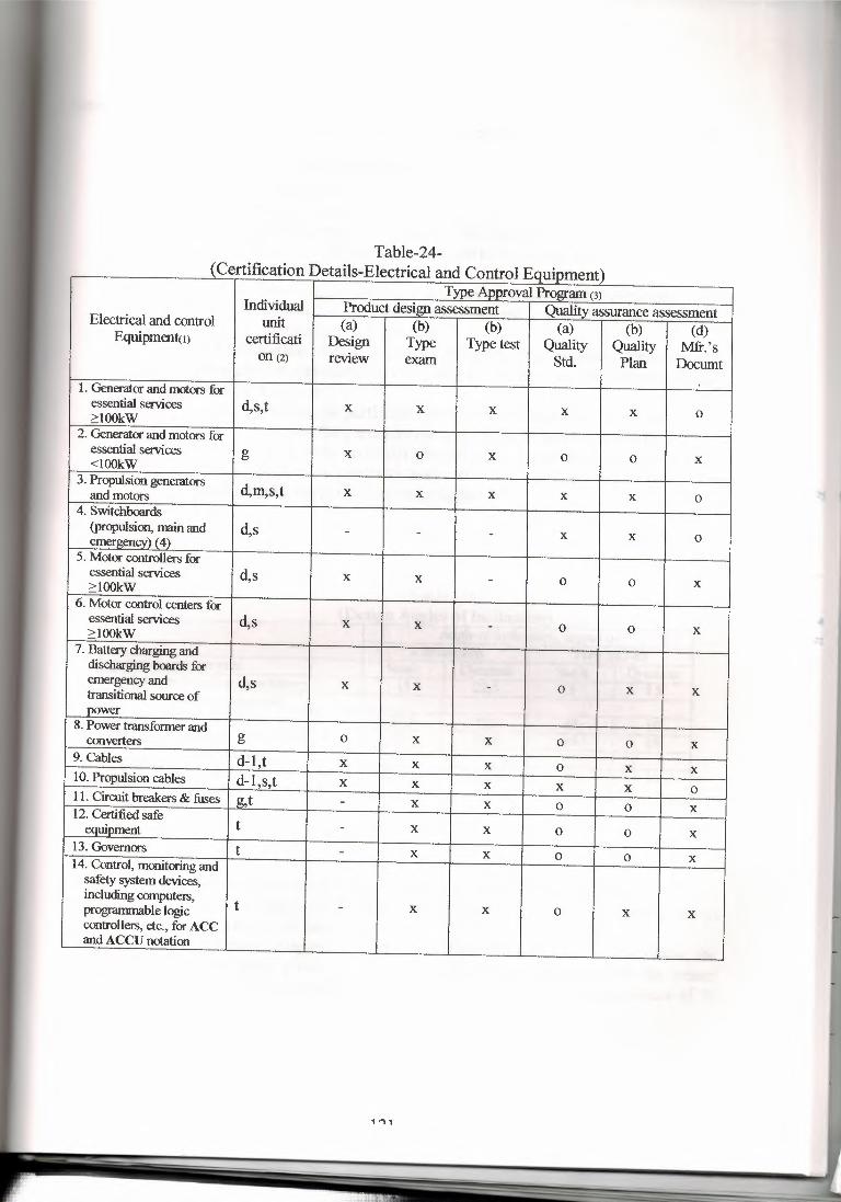
-- ·1.- ------·,,
Type Approval Program (3) Individual Product design assessment Quality assurance assessment Electrical and control unit (a) (b) (b) (a) (b) (d) Equipmentm certificati Design Type Type test Quality Quality Mfr.'s on (2) review exam Std. Plan Documt
1. Generator and motors for essential services d,s,t X X X X X 0 >lOOkW
2. Generator and motors for essential services g X 0 X 0 0 X <lOOkW
3. Propulsion generators d,m,s,t X X X X X 0 and motors
4. Switchboards (propulsion, mun and d,s - - - X X 0 emerzencvi ( 4)
5. Motor controllers for essential services d,s X X - 0 0 X >lOOkW
6. Motor control centers for essential services d,s X X - 0 0 X >lOOkW
7. Battery charging and discharging boards for emergency and d,s X X - 0 X X transitional source of now er
8. Power transfonner and converters g 0 X X 0 0 X
9. Cables d-1,t X X X 0 X X 10. Propulsion cables d-1,s,t X X X X X 0 11. Circuit breakers & fuses g,t - X X 0 0 X 12. Certified safe t equipment - X X 0 0 X
13. Governors t - X X 0 0 X 14. Control, monitoring and safety system devices, including computers,
t - X X 0 X X programmable logic controllers, etc., for ACC and ACCU notation
{Certifi Table-24-
Details-Electrical and C lE 2
1,., 1
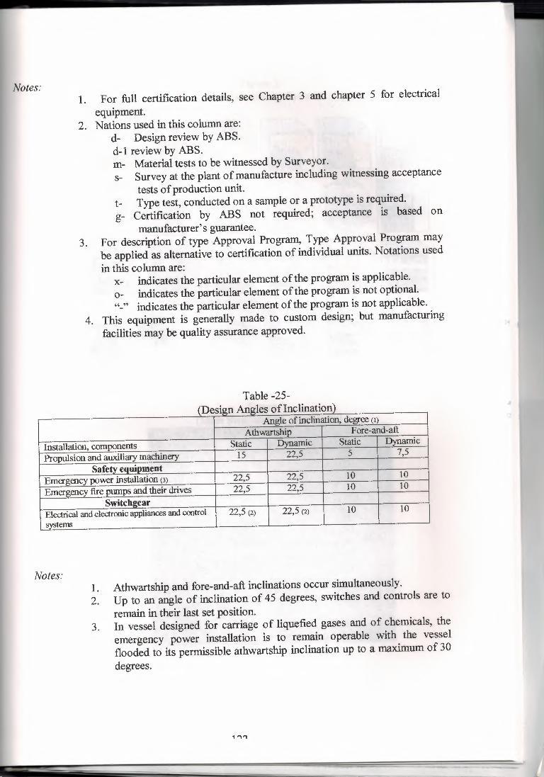
Notes: 1. For full certification details, see Chapter 3 and chapter 5 for electrical
equipment. 2. Nations used in this column are:
d- Design review by ABS. d-I review by ABS. m- Material tests to be witnessed by Surveyor. s- Survey at the plant of manufacture including witnessing acceptance
tests of production unit. t- Type test, conducted on a sample or a prototype is required. g- Certification by ABS not required; acceptance is based on
manufacturer's guarantee. 3. For description of type Approval Program., Type Approval Program. may
be applied as alternative to certification of individual units. Notations used in this column are:
x- indicates the particular element of the program. is applicable. o- indicates the particular element of the program. is not optional. "-" indicates the particular element of the program. is not applicable.
4. This equipment is generally made to custom design; but manufacturing facilities may be quality assurance approved.
Table -25- \ i.J,.,,..j,,,Jl.115..a..a .•...••••. .l~ •• -.., _. - ---- ----- -
Angle of inclination, degree (1) Athwartship Fore-and-aft
Installation, components Static Dynamic Static Dynamic
Propulsion and auxiliary machinery 15 22,5 5 7,5
Safety equipment Emergency power installation (3) 22,5 22,5 10 10
Emergency fire pumps and their drives 22,5 22,5 10 10
Switchaear Electrical and electronic appliances and control 22,5 (2) 22,5 (2) 10 10
systems
Notes: 1. Athwartship and fore-and-aft inclinations occur simultaneously. 2. Up to an angle of inclination of 45 degrees, switches and controls are to
remain in their last set position. 3. In vessel designed for carriage of liquefied gases and of chemicals, the
emergency power installation is to remain operable with the vessel flooded to its permissible athwartship inclination up to a maximum of 30 degrees.
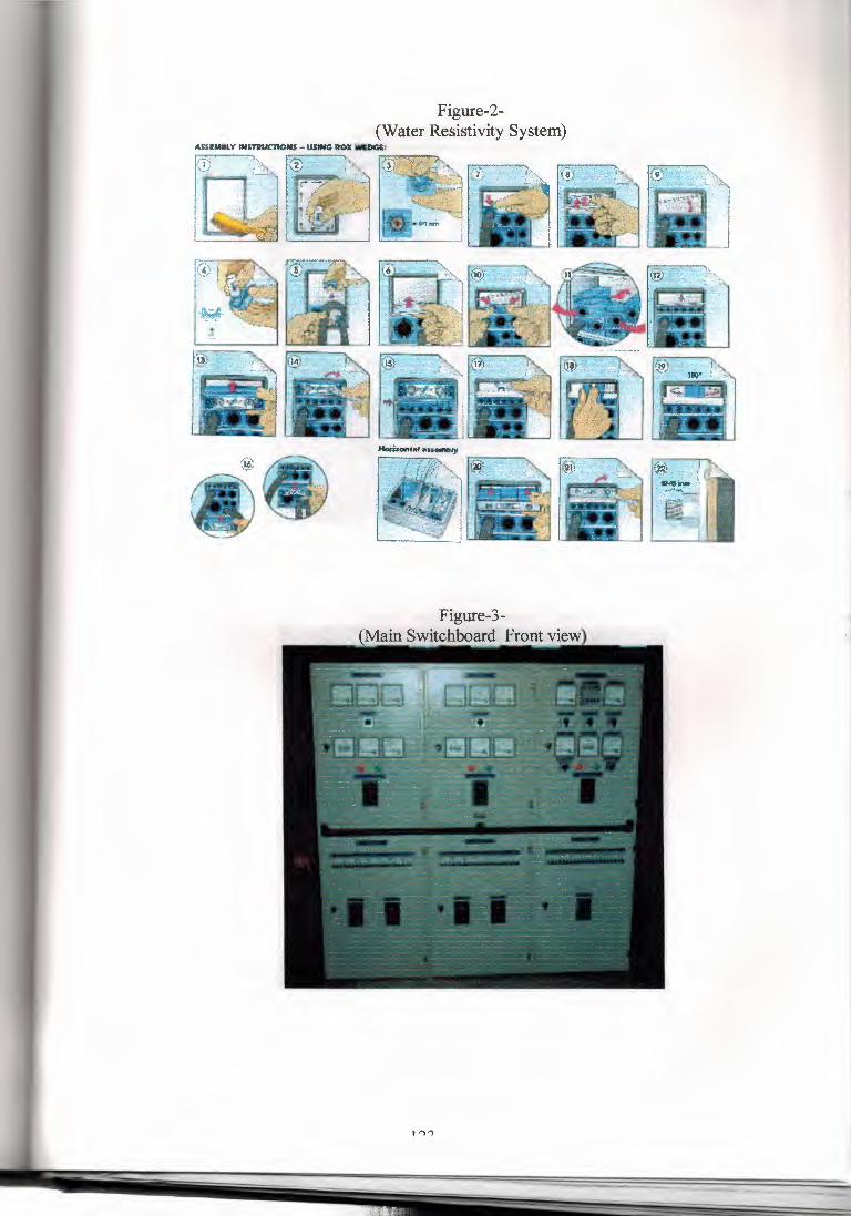
Figure-2- (Water Resistivity System)
ASS:lliM8LY IN$Tllllt:JtOHS - USING ROX __ ,
Figure-3- (¥ainS>Yitchboard ):rout view
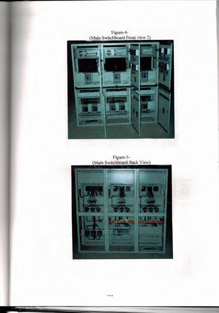
Figure-4- (Main Switchboard Front view 2
Figure-5- Main Switchboard Back View
_J 1 ., . , .
1,.., ,t
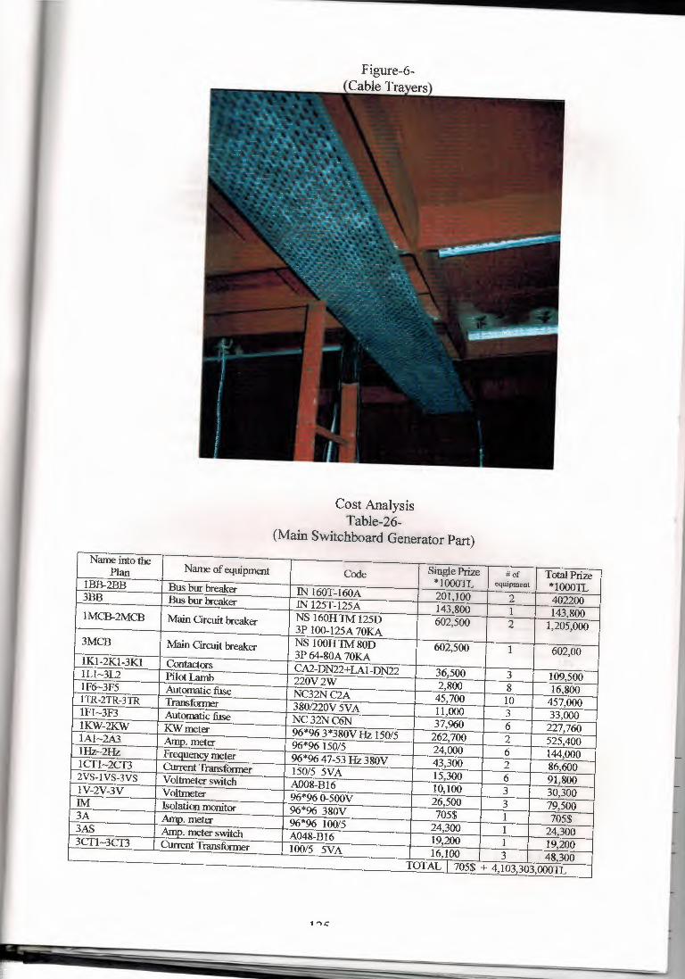
Cost Analysis Table-26-
(Main Switchboard Generator Part) Name into the
Name of equipment Code Single Prize #of Total Prize Plan *100011., equipment *10001L 1BB-2BB Bus bur breaker IN 160T-160A 201,100 2 402200 3BB Bus bur breaker IN 125T-125A 143,800 1 143,800 1MCB-2MCB Main Circuit breaker NS 160H1M 125D 602,500 2 1,205,000 3P 100-125A 70KA
3MCB Main Circuit breaker NS lOOH 1M 80D 602,500 1 602,00 3P 64-80A 70KA 1Kl-2Kl-3Kl Contact ors CA2-DN22+LA1-DN22 36,500 3 109,500 lLl-312 Pilot lamb 220V2W 2,800 8 16,800 1F6-3F5 Automatic fuse NC32NC2A 45,700 10 457,000 11R-2TR-31R Transfonner 380/220V 5VA 11,000 3 33,000 1Fl-3F3 Automatic fuse NC32NC6N 37,960 6 227,760 1KW-2KW KW meter 96*96 3*380V Hz 150/5 262,700 2 525,400 1Al-2A3. Amo. meter 96*96150/5 24,000 6 144,000 1Hz-2Hz Frequency meter 96*96 47-53 Hz 380V 43,300 2 86,600 1CTI-2CT3 Current Transforrner 150/5 5VA 15,300 6 91,800 2VS-I VS~3VS Voltmeter switch A008-Bl6 10,100 3 30,300 1V-2V-3V Voltmeter 96*96 0-500V 26,500 3 79,500 IM Isolation monitor 96*96 380V 705$ 1 705$ 3A Amo. meter 96*96 100/5 24,300 1 24,300 3AS Amo. meter switch A048-Bl6 19,200 1 19,200 3CT1-3CT3 Current Transfonner 100/5 5VA 16,100 3 48,300 TOTAL I 705$ + 4,103,303,000JL
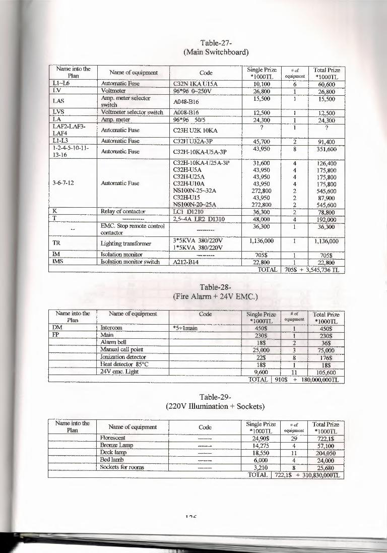
Table-27- (Main Switchboard)
Name into the Name of equipment Code Single Prize #of Total Prize Plan *10001L equipment *10001L
Ll-L6 Automatic Fuse C32N lKA Ul5A 10,100 6 60,600 LV Voltmeter 96*% 0-250V 26,800 1 26,800 LAS Amp. meter selector A048-Bl6 15,500 1 15,500
switch LVS Voltmeter selector switch A008-Bl6 12,500 1 12,500 LA Amo. meter 96*96 50/5 24,300 1 24,300 LAF2-LAF3- ? 1 ? LAF4 Automatic Fuse C23H U2K lOKA
Ll-L3 Automatic Fuse C32H U32A-3P 45,700 2 91,400 1-2-4-5-10-11- Automatic Fuse C32H-1 OKA-U5A-3P 43,950 8 351,600 13-16
C32H-1 OKA-U25A-3P 31,600 4 126,400 C32H-U5A 43,950 4 175,800 C32H-U25A 43,950 4 175,800
3-6-7-12 Automatic Fuse C32H-UlOA 43,950 4 175,800 NS100N-25-32A 272,800 2 545,600 C32H-Ul5 43,950 2 87,900 NS100N-20-25A 272,800 2 545,600
K Relav of contactor LCl Dl210 36,300 2 78,800 T ____ ..,_ 2 5-4A LR2 D1310 48,000 4 192,000
EMC. Stop remote control 36,300 1 36,300 - contact or ------- TR Lighting transformer 3*5KVA 380/220V 1,136,000 1 1,136,000
1*5KVA 380/220V IM Isolation monitor ------ 705$ 1 705$ IMS Isolation monitor switch A212-B14 22,800 1 22,800
TOTAL 705$ + 3,545,736 JL
Table-28- (Fire Alarm+ 24V EMC.)
Name into the Name of equipment Code Single Prize # of Total Prize Plan *10001L equipment *10001L
DM Intercom *5+lmain 450$ 1 450$ FP Main 230$ 1 230$
Alarm bell 18$ 2 36$ Manual call point 25,000 3 75,000 Ionization detector 22$ 8 176$ Heat detector 85°C 18$ 1 18$ 24V emc. Li!ilit 9,600 11 105,600
TOTAL I 910$ + 180,000,000JL
Table-29- (220V Illumination+ Sockets)
Name into the Name of equipment Code Single Prize # of Total Prize Plan *10001L equipment *10001L
Florescent ----- 24,90$ 29 722,1$ Bronze T amn ------ 14,275 4 57,100 Decklamo --- 18,550 11 204,050 Bed lamb ----- 6,000 4 24,000 Sockets for rooms --- 3,210 8 25,680
TOTAL I 722,1$ + 310,830,000JL
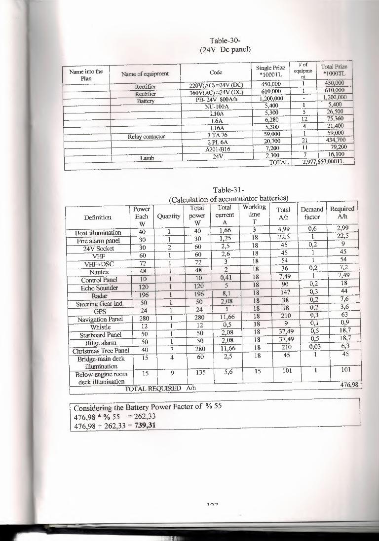
Table-30- (24V De panel)
Name into the Single Prize #of Total Prize Name of equipment Ccxle equipme
Plan *lOOOTI.. nt *lOOOTI..
Rectifier 220V(AC) ~4V (DC) 450,000 1 450,000
Rectifier 360WAC) ~4V (T)C) 610,000 1 610,000
Batterv PB- 24V 800Alh 1,200,000 - 1,200,000 NU-lOOA 5,400 1 5,400 LIOA 5,300 5 26,500 L6A 6,280 12 75,360 L16A 5,300 4 21,400
Relav contactor 3TA76 59,000 1 59,000 2PL6A 20,700 21 434,700 A201-Bl6 7,200 11 79,200
lamb 24V 2,300 7 16,100 TOTAL 2,977 ,660,000TI..
Power Total Total Working Total Demand Required Definition Each Quantity power current time AJh factor AJh
w w A T
Boat illumination 40 1 40 1,66 3 4,99 0,6 2,99
Fire alarm panel 30 1 30 1,25 18 22,5 1 22,5
24VSocket 30 2 60 2,5 18 45 0,2 9
VHF 60 1 60 2,6 18 45 1 45
VHF+DSC 72 1 72 3 18 54 1 54
Nautex 48 1 48 2 18 36 0,2 7,2
Control Panel 10 1 10 0,41 18 7,49 1 7,49
Echo Sounder 120 1 120 5 18 90 0,2 18
Radar 196 1 196 8,1 18 147 0,3 44
Steering Gear ind. 50 1 50 2,08 18 38 0,2 7,6
GPS 24 1 24 1 18 18 0,2 3,6
Navigation Panel 280 1 280 11,66 18 210 0,3 63
Whistle 12 1 12 0,5 18 9 0,1 0,9
Starboard Panel 50 1 50 2,08 18 37,49 0,5 18,7
Bilge alarm 50 1 50 2,08 18 37,49 0,5 18,7
Christmas Tree Panel 40 7 280 11,66 18 210 0,03 6,3
Bridge-main deck 15 4 60 2,5 18 45 1 45
illurnination Below-engine room 15 9 135 5,6 15 101 1 101
deck ilhnnination TOT AL REQUIRED AJh 476,98
Table-31- ( Calculation of accumulator batteries)
Considering the Battery Power Factor of % 55 476,98 * % 55 = 262,33 476,98 + 262,33 = 739,31