
Near East University Docs
108
1988 N%AR %AST UNIV%RSITY FACULTY OF %NGIN%%RING D%PARTl\ıI%NT OF %L%CTRICAL AND %L%CTRONICS %NGIN%%RING DIGITAL SAT%LLIT% COMMUNICATION SYST%M (BASIC CONC%PTS. ARCHIT%CTUR%) GRADUATION PROJ%CT- "%%-400" B.SC. %NGIN%%RING PROJ%CT SUBMITT%D BY Ali HASHMI (970976) SUP%RVIS%D BY Prof. Dr. FaKhreddin MA~I%DOV NICOSIA- 2000 (JANUARY) \ ----:-_-..::::;:.:;..
-
Upload
khangminh22 -
Category
Documents
-
view
2 -
download
0
Transcript of Near East University Docs

1988
NEAR EAST UNIVERSITY
FACULTY OF ENGINEERING
DEPARTl\ıIENT OF ELECTRICAL ANDELECTRONICS ENGINEERING
DIGITAL SATELLITE COMMUNICATIONSYSTEM
(BASIC CONCEPTS. ARCHITECTURE)
GRADUATION PROJECT- "EE-400"
B.Sc. ENGINEERING PROJECT
SUBMITTED BY
Ali HASHMI (970976)
SUPERVISED BY
Prof. Dr. Fakhreddin MA~IEDOV
NICOSIA- 2000 (JANUARY)
\
----:-_-..::::;:.:;..

.
ACKNOWLEDGEMENT
One of the pleasures of authorship isacknowledging the many people whosenames may not appear on the cover butwithout whose efforts; co-operation andencouragement a work of this scope neverhave been completed.
I am much indebted to
Prof. Dr. Fakhreddin MAMEDOV
For his kind supervision, generousadvice, clarifying suggestions and supportduring the whole scope of this work.
In the end, I would like to thank my familyfor their support during my education.

ABSTRACT
DURING the past few years, the importance of Digital SatelliteCommunication, has increased rapidly. The accumulation of a vast body ofengineering literature in the various technical journals has accompanied thedesign and development of digital system, and launch of satellite. There areseveral objectives of this project; which are as fellows :
• Realising in details all about the History Of Digital SatelliteCommunications.
• Understanding how to fix a satellite in its accurate orbit which is at aconstant distance from the earth.
• Covering the concepts of multiple access techniques.
• Dealing with the whole systems of Satellite Communications, such asEarth Stations, Satellite Link, available antennas in this field andSatellite Transponders, ETC.
• Studying several Digital Communication Techniques.
• Studying Time Division Multiple Access in details.

CONTENTS
CHAPTER 1: HISTORY OF SATELLITE COMMUNICATION
1.1 History .l
1.2 Satellite Communication Architecture 2
CHAPTER 2: BASIC CONCEPTS OF SATELLITE COMMUNICATION
2.1 Introduction 4
2.2 Satellite Orbits 4
2.3 Antennas .17
2.4 Launchers and Launching 21
CHAPTER3: DIGITAL COMMUNICATIONS & MULTIPLE ACCESS
3.1 Introduction 26
3.2 Digital Radio 26
3.3 Frequency and Time Division Multiplexing. 27
3.4 Multiple Access 29

CHAPTER 4: SATELLITE TRANSPONDER
4.1 Introduction 34
4.2 Space Craft Subsystem 34
4.3 The Electrical Power Supply 47
4.4 Antenna Sub-System 54
4.5 Satellite System Link Models 61
CHAPTER 5: EARTH STATION-
5.1 Introduction 64
5.2 Design Consideration 66
5.3 General Configuration 67
5.4 Characteristics of Earth Station 74
CHAPTER 6: TDMA ACESS
6.1 Introduction 77
6.2 The System Concept and Configuration 78
6.3 System Timing 80
6.4 TDMA Frame Rates and Formats 91
6.5 TDMA System Efficiency 95
6.6 TDMA Carrier Recovery Using Frame-Frame Coherence 96
6.7 Deleted Reference Carrier Recovery for TDMA. .100
11

CHAPTER! HISTORY OF SATELLITE COMMUNICATIONS
1.1 HISTORY
In 1945 ARTHUR CLARK wrote that satellite with a circular equatorial orbit at a correct
altitude of 35,786 km would make one revolution every 24 hour ;that is, it would rotate at
the same angular velocity as the earth. An observer looking at such a geostationary satellites
powered by solar energy could provide world wide communications for all possible types of
services. The "space race" and a sustained effort followed the 1957 launch of SPUTNIK 1
by the United States to catch up with the USSR. The first communications satellites to draw
widespread popular interest (because on clear nights they were visible to the naked eye)
were ECHO-I and II, launched by AT&T on August 12, 1960, and January 25,1964. These
were orbiting balloons 100 ft in diameter, which served as passive reflectors. As such, they
had no transponder batteries to run down, and they did not require a strict frequency
channellingof up-link signals to accommodate transponder input bands. On the other hand,
they operated like radar reflectors and incurred path losses that were proportional to the
fourth power of path length rather than to the square of path length as is the case with active
satellites. This as well as the available launch vehicles limited the ECHO's to very low orbits
with periods of 118 min for ECHO 1 and 108.8 min for ECHO 11. Low orbits meant that an
ECHO was in view of two widely separated earth stations for only a few minutes on each
pass. Power and antenna requirements were severe; a typical ECHO link from Bell
Laboratories in New Jersey to the Jet Propulsion Laboratory in California used 10 kW
transmitter at ends, an 85 ft dish in California, and a 60 ft dish in New Jersey. Typical
frequencieswere 960 MHz westbound and 2390 MHz eastbound.
In 1963 Congress passed the Communications Satellite Act.; establishing the
CommunicationsSatellite Co-operation (Comsat) and barring the Bell System from further
direct participation in satellite communications.While we will not go into the many
conflictingreasons why this should or should not have been done (the authors have friends
who are involved on all sides ofmatter), this caused considerable bitterness in the Bell
1

System. Which had invested substantial resources in the ECHO and TELSTAR programs.
The Bell· engineers involved felt that, once their company proved that communications
satellites would work, the opportunity to profit by their investment was taken away and
given to someone else. Unhappiness over this situation persisted well into 1970s and the
restriction ultimately was lifted.
The first commercial geosynchronous satellite was INTELSAT 1 (first called EARLY
BIRD), developed by Comsat for Intelsat. launched April6, 1965, it remained active until
1969. Routine operation between the United States and Europe began on June 28, 1965, a
date that should be recognised as the birthday of commercial satellite communications. The
spacecraft had two 25 MHz bandwidth transponders with up-links centered at 6301 MHz
for Europe and 6390 MHz for the United States. U. S. receivers operated with a 4081 MHz
center frequency and the European down-links band was centered at 4161 MHz . With this
spacecraft the modern era of Satellite communications had begun.
1.2 SATELLITE COMMUNICATIONS EXPERIMENTS
Among other fields space activity at this time, the USA carried out a series of
communication satellite experiments, involving NASA or the US Army, using passive
reflectors in space, such as the Echo and West Ford projects, and active relaying satellites,
such as Score and Courier. This programme, using active satellites, was continued by NASA
with the six satellites of Applications Technology Satellites (ATS) series with launching
running through the 1960s and was recently revived by the launch of Advanced
Communications Technology Satellite (ACTS) in 1993.
Syncom was another important early project, designed primarily to develop and refine
techniques for launching satellites into the GSO. The Hughes Aircraft Company supplied
three satellites. Syncom 1 was launched on 14 February 1963 into an orbit that was
approximately geosynchronous, with an orbital inclination of 3 3. 5° , but its communication
system failed in the final stages of orbit adjustment. Syncom 2 was launched on 26 July 1963
2

into a more accurate geosynchronous orbit, its inclination was 33. l 0, and its communications
system remained functional. Syncom 3 was' highly successful being launched on 19 August
1994 into an almost geostationary orbit, approximately circular, its orbital period almostexactly equal lo one Side real day and its inclination a mere O. I 0.
IC'le·::sıorıu,-.ııınıılıcııı
\,11Pllı\ı:\
l~l.-.:1,o,rl,.ıl,,xylırn,ıd,a<.ııııy
(nud- 19ao,ı I"-..._,Fixı?d
cornmunica tıonsaud lıroadcasling
saiellite.s
Tel<"Con1DFS
(198Usl ~
DTI 1 ~:~~'1'.:~; newE·u.le ls at ~ bro.ı c . ·aıııed
ı ~ spec,/\stra· Dir ec t Tv / systems(rrnd·1930~ Hol Uird
-- Ectros tar ~(mid.\ 990s)lıxed __
cornmurıi_f.ı1lıor -s.aıel!ılC'S
radio
mutupur povecornrnunıc- o nons
~ s.ncn.rcs
OıiooP,-ınAnı\at
dı~,111\Juı,oıı
(\ <J~(h) Woı ldSp,1<-f"
lixcı.J ,ıpplıcJtıoııs (200th) ! tımı.:
ıııobi1ı• .,pplu:.,ıtıoıı\··-- - - - - - - - - - - - - ,..
mobrlo vo«,v'l,ıtelliln
()II(' \'V,)y
uplınk
-·----·-1lricJiuııı /ICQ
[I Globals ı ar ~.
//~ !:~(J'.:·,ı_
or-sGLONJ\SS
IIP\I'/
~JlP(ialı,ı-::>d<;y~l('ın\
\ ırıohılC>\ (0111nıurnc..ıln:.1ı,'i
\ ),1\(111\l")
/lrun ar s a t
(ınır_1. \ ':-'~)()ı,)
-,I
Or Uc.oının \,,..~ .
,.•T.1,I .J':".lCJ)
DTI I = direct tu Iıuıııc
FIGURE 1.1
3

CHAPTER2 SATELLITE COMMUNICATIONS
2.1 INTRODUCTION
Satellites (spacecraft) which orbit the earth follow the same laws that govern the motion
of the planets around the sun. From early times much has been learned about planetary
motion through careful observations. From these observations Johannes Kepler
(1571-1630) was able to derive empiricallythree laws describing planetary motion.
Later, in 1665, Sir Isaac Newton (1642-1727) was able to derive Kepler's laws from his
own laws of mechanics and develop the theory of gravitation. Kepler's laws apply quite
generally to any two bodies in space which interact through gravitation. The more
massive of the bodies is referred to as the primary, the other the secondary, or satellite.
• Satellite Communications networks are one of the most major telecommunicationssystem.
• Satellites have a unique capability for providing coverage over large geo-graphicalareas.
• The resulting interconnectivity between communications sources provides major
advantages in applications such as:
Telephone exchange , Mobile communications, Television and sound broadcasts directlyto the public.
•
2.2 SATELLITE ORBITS
2.2.1 Geo-synchronous and Geo-stationary Orbits
a. Basic Orbital Characteristics
The Earth's sidereal period of rotation, that is, the time taken for one complete rotation
about its center of mass relative to the stellar background, is one sidereal day,
approximately 23 hours 6 minutes 4 seconds. If a satellite has a direct, circular orbit and
its period of revolution measured as above, is equal to one sidereal day, it will keep pace
with the turning Earth; that is, it is a geo-synchronous satellite. The radius of its orbit (rg)
will be 42164 km and its height above the earth's surface will be about 3 5786 km. If this
satellites daily Earth track (that is, the locus of the points on the earth's surface that are
verticallybelow the satellite at any instant) is traced, it will show a figure of eight pattern
4

5
as sketched in Figure 2.1 (a)
3o•N-=---..:_---~
---~ı I ı~-- o .• -
(a) (h)
FIGURE 2.1
The maximum extent of the pattern in degrees of latitude, north and south of the
equator, is equal to the angle of inclination of the orbit. Provided that the orbit is indeed
circular, the north-going track crosses the equator at the same longitude as the south
going track and the pattern is symmetrical about that central lino of longitude. However,
if the orbit is elliptical, the cross- over point of the north-going and south-going tracks is
no longer located in the equatorial plane and the pattern becomes asymmetrical; see for
example, Figure 2.1 (b).
The maximum spread of the pattern, east and west of the central line of longitude is
given by
Maximum spread =±arcsine (sin" 'hi I cos" 'hi )
The Geo-stationary satellite orbit (GSO), like other orbits, is unstable. There are orbital
perturbations that are tending all the time to change its period, inclination and shape from
the Geo-stationary parameter set.
lJ. Advantages
The GSO is better for the most communication systems than any other orbit. The reasons
for this are:
1. Above all, one satellite can provide continuous links between earth stations. An
inclined gee-synchronous satellite can do this also, although the gee-graphical area that
can be served is more limited if the angle of inclination is large.
The disadvantages of using satellites with an orbital period of less than one sidereal day

for systems that are required to provide continuous connections.
2. The gain and radiation pattern of satellite antennas can be optimized, so that the geo
graphical area illuminated by the beam, called the footprint, can be matched accurately to
the service area, yielding significant benefits .
3. The geo-graphical area visible from the satellite, and therefore potentially accessible
for communication, is very large; see Figure 2.2 the diameter of the area with in which
the angle of elevation a of a geo-stationary satellite is greater than 5° is about 19960
km.
4. If the orbit is accurately geo-stationary, earth station antennas of considerable gain can
be used without automatic satellite tracking reducing equipment cost and minimizing the
operational attention required.
5. The frequency assignment used in different geo-stationary satellite networks can be
coordinated efficiently, the satellite footprints can be matched to the service areas, and
earth station antennas usually have high again.
•
c. Disadvantages
1. A satellite link from earth to station via a geo-stationary satellite is very long.
2. As can be seen from Figure 2.2 the angle of elevation of the satellite as seen from
earth stations in high latitudes is quite low, leading at times to degraded radio
propagation and possible obstruction by hills, buildings, and so on.
FIGURE 2.2
6

d. Perturbations Of Geo-stationary Orbits
The drag of the atmosphere on a satellite in a 24-hour circular orbit is negligible.
However, there are three kinds of orbital perturbation, which tend to move the
parameters of the orbit of geo-stationary satellite away from the nominal values. They
are the gravitational effect of irregularities of the Earth's figure, the gravitational
attraction of the Sun and Moon and solar radiation pressure.
2.2.2 Inclined Elliptical Orbits
a. Basic Orbital Characteristics
The shape of an ellipse is characterized by its eccentricity €, where:
E = (1- b2 I a") Y,
and a and b are the semi- major and semi-minor axes of the ellipse. There are two foci
located on the major axis and separated from the origin of the ellipse by distance c,
where
•
For an Earth satellite with an elliptical orbit, one of the foci is located at Q, the center of
mass of the Earth. The points on the orbit where the satellite is most and least distance
from the Earth are called the apogee and the perigee respectively. The greatest and least
distances from the surface of the earth, the altitudes of apogee and perigee ha and hp, are
given by
ha = a( I + E ) - RE
and
hr = a( 1- E) - RE
E = (1- b2/a2ta, b are semi - major and semi-minor axes of the ellipse .1 These various terms are
illustrated in Figure 2.3
7
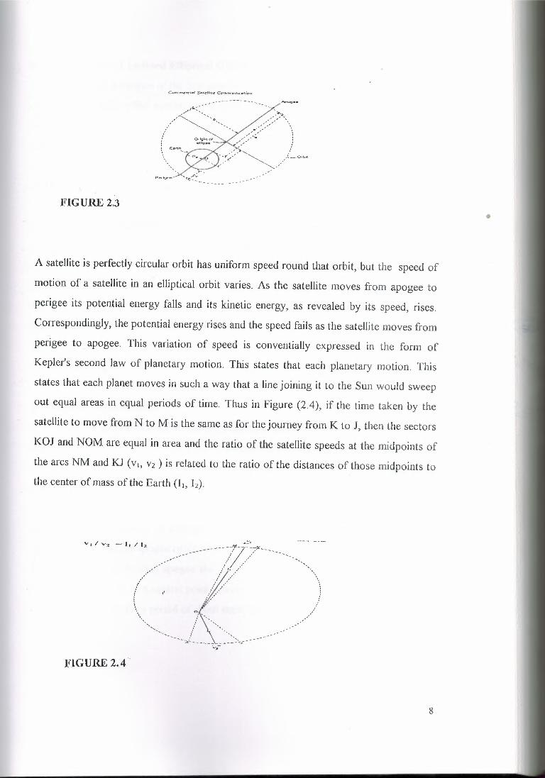
FIGURE2.3
A satellite is perfectly circular orbit has uniform speed round that orbit, but the speed of
motion of a satellite in an elliptical orbit varies. As the satellite moves from apogee to
perigee its potential energy falls and its kinetic energy, as revealed by its speed, rises.
Correspondingly, the potential energy rises and the speed fails as the satellite moves from
perigee to apogee. This variation of speed is conventially expressed in the form of
Kepler's second law of planetary motion. This states that each planetary motion. This
states that each planet moves in such a way that a line joining it to the Sun would sweep
out equal areas in equal periods of time. Thus in Figure (2.4), if the time taken by the
satellite to move from N to M is the same as for the journey from K to J, then the sectors
KOJ and NOM are equal in area and the ratio of the satellite speeds at the midpoints of
the arcs NM and KJ (vı, vs ) is related to the ratio of the distances of those midpoints to
the center of mass of the Earth (L, h).
FIGURE 2.4
8
•

9
b. Perturbations Of Inclined Elliptical Orbits
The gravitational attraction of the Sun and the Moon and the pressure of solar radiation
on the satellite body affect satellites with inclined elliptical orbits in much time the same
way as they affect geo-stationary satellites. However, these effects are small compared
with the effect of the oblateness of the Earth on the argument of perigee . Moreover,
some elliptical orbits, having a quite small height at perigee, suffer considerable orbit
modification through aerodynamic drag.
c. The Earth Coverage Of Satellites In Elliptical Orbits
Satellite in orbits of substantial eccentricity spend most of each orbital period at a high
altitude, close to the height of their apogee, from which they can cover a large footprint.
In general they are of little use at low altitude, near to perigee. The systems that might
find such orbits ofvalue are national or regional in coverage rather than global. Thus it is
necessary to choose an orbital period and to control precession of the argument of
perigee to stabilize the Earth track, to ensure that the point on the Earth directly beneath
the apogee should be consistently located at an appropriate point in the service area.
d. High Latitude Coverage
A point on the surface of the Earth sweeps through right ascension at a constant rate of
approximately 3600 /24 = 15° per hour. A satellite in a direct elliptical orbit with period
of T (hours) sweeps through right ascension in the same direction as the earth and at an
average rate of 360°/ T per hour, although the rate will be considerably less than the
average near apogee and more than the average near perigee . The Earth track of the
Molniya orbit, centered as an example on longitude 0°, is sketched in Figure 2.5 . The
satellite passes through apogee twice each day, at about the same location in the celestial
frame of reference. At each apogee the satellite is seen from the Earth's surface to be
within a few degrees of a central point around latitude 60° N and, for this Example, at
longitude 0° or 180° for a period of about eight hours.

63.4N' A,2 A1
Sou1if0 edge_ , of ar:- cove,ed-------<" fr mA,
,·--...... ~ I __..,,,.,.,.,,
63.4 S ~~ :~---ı
ıoo 90W OLongitude (degıccs)
<,>OE
•FIGURE 2.5
e. Short Orbital Period
Satellite in circular orbits with height above the Earth of 8000 km have an orbital period
of 4. 7 hours; 12 satellites in phased orbits might be needed to provide continuous
coverage of a service area that is continental in extent. A satellite with an elliptical orbit
having a period of two hours might also have a height above the Earth's surface at
apogee of 8000 km, depending on the eccentricity of its orbits.
f. Medium- Altitude Orbits
Geo-stationary satellites have great advantages for communications applications where
polar coverage is not required. In the early days of satellite communication, it was feared
that one-way transmission times exceeding 250 ms might be an unacceptable impediment
to telephone conversation. Geo-stationary satellite seems likely to continue to dominate
satellite communications with high- capacity links between fixed points. However, there
has recently been a revival of interest in using medium-altitude orbits for serving mobile
Earth stations, because, compared with the GSO, the transmission loss is lower.
It is fortunate that the GSO has been found acceptable for trunk telecommunications.
because tile use of lower orbits such as MEO's for this purpose would involve major
additional problems and costs.
IO

11
2.2.3 Orbital Perturbations For MEO's And LEO's
Satellite in medium-altitude or low circular orbits is, of course, subject to ORBITAL
PERTURBATIONS. For very low orbits, the aerodynamic drag is likely to be
significant. However, some of the other perturbations, such as precession of the
argument of perigee, resolve to zero if the orbit is circular or polar. In general, a
perturbation is unlikely to have a serious effect on the operation of a multi-satellite
constellation since it will usually affect all the satellites of the constellation in equal
measure.
2.2.4 Low Earth Orbits(LEO) Systems
Satellite with altitudes in the approximate range of 100-1000 miles is referred to as Low
Earth Orbit (LEO). They circle the earth every few hours. In the following pages we are
going to show two examples of satellite mobile service systems, Iridium and Global-Star
systems, which are considered as LEO systems.
2.2.5 The Iridium System
Engineers at Motorola's satellite communication division in 1987 originated the iridium
concept. Originally envisioned as consisting of 77 satellites in low earth orbit, the name
Iridiumwas adopted by analogy with the element Iridium, which has 77 orbital electrons.
Further studies led to a revised constellation plan requiring only 66 satellites. Because of
the international character of satellite communications, an international consortium of
telecommunications operator and industrial companies, called Iridium Inc., was formed
to implement and manage the Iridium system .
Description Of The System
The system consists of six orbital planes, each containing 11 active satellite. The orbits
are circular at height of 783 km. Pro-grade orbits are used, the inclinationbeing 86°. The
11 satellites in any given plane are uniformly spaced, the normal spacing being 32.7°. An
in-orbit spare is availablefor each plane at an orbit 130 km lower in orbital plane.

12
FIGURE 2.6
The satellite travels in co-rotating planes that they travel up one side of the earth cross
over near the north pole, then travel down the other side . Since there are 11 equi-spaced
satellites in each plane, it will be seen that the entire earth is continuously covered. The
satellites in adjacent plane travel out of phase Figure (2.6), collision avoidance is built
into the orbital planning, and the closest approach between satellites is 223 km. Satellites
in planes 1,3 and 5 cross the equator in synchronizationwhile satellites in plane 2,4 and 6
also cross in synchronizationbut of phase with those in planes 1. 3 and 5. The separation
between planes is 31.6°, which allows 22° separation between the first and last planes.
The closer separation is needed because the earth coverage under the counter rotating
"seam" is not as efficient as it under the co-rotating seams. There are two-way
communication links between satellites as shown in Figure (2.6), ahead and front, and to
the satellites in adjacent planes. The up/down links between subscribers and satellites
take place in the L-band. A 48-beam antenna pattern is used from each satellite. with
each beam under separate control. The orbital period is approximately 100 min., and
taking an average value of 6371 km for the earth's radius. the surface speed is 2x 6371x
n/100 ~ 400 km/min or just over the 15,000 mile/hour. The 48 cell pattern and earth
coverage is shown in Figure (2.8).

13
·~-- 1
----···
---------.
. I \.[_ ____.__FIGURE 2.7 FIGURE 2.8
2.2.6 The Global Star System
Loral Qualcomm Satellite Services company develop the Global-Star system at 1944.
The first group is supposed launched in mid 1997, service will begin in mid 1998, and full
service will be in 1999. Global-Star use of:MMA technology allows users to connect to
multiple satellites, improves signal quality, eliminates interference, and disconnects cross
talk and loss of data.
a. The Space Segment
A space segment consists of a constellation of 48 satellites in eight planes (6 satellites I
plane plus 8 satellites on standby) inclined at 52° relative to the equator will be deployed
as shown in figure (2.9). In this system the operating frequencies are 1. 6 GHz & 2.5 Hz
instead of 800-900 grams used by terrestrial systems for mobiles & C-band for
gateways. The frequency plan is shown in figure (2.1 O), which illustrates the link
between the Mobil, and the gateway in both forward and return links. Satellites at a
height of 1410 Km (750 nautical mile.), provide coverage areas as great as 5000 Km
(2600 nautical mile) in diameter compared to 20 Km provided by terrestrial system
employing20 m high towers.

=======:;;;..;;c...:.;··:=· ·=-- GLOBALSTAR'S
ı CO~TELl...A,.IOH ARClttTECTUf?':E I~ BATELUTE9 IN. ORBIT PLAN( S
eae ORBITAL INCUNA'TION.9 WITHSATELLITES 1"4 7S0 N.. MJ Of\DITS
HtOH-CAPAClfY MVl.TTPLE SJ\TELlllECOV£RAOE BETWEEN .t,:o0 LAT1tuoe
FIGURE 2.9
l THE.-GLOBALSl'.AA. SYSTEM I• U91!!!1~Xl5TINO TE.LECOMMUNCCI\TIONS
INFRAST,..UCTtJ,:te
MOBfLl!:•TO-MOBfl..l! CALJ..9:EACH US'ER CONNECT!I TO ASATELI..ITE ~O A OATEWAY
b. The User Segment
Handheld & mobile unites are similar to standard cellular telephones hut operate in dual
mode with the local cellular system or through Global-Star. Dual mode means that some
mobile terminals will be able to operate in a cellular network and in the Global-Star
network, but singlemode means that these operate only with the Global-Star system.
c. The Ground Segment
Global-Star system is comprised of gateways-earth terminals throughout the world that
connect the Global-Star satellite constellation to the land-based switching equipment of
terrestrial and cellular telecommunications service providers. Certain gateways also
manage the Global-Star communication networks for call verification, billing as well as
monitor and control each satellites performance.
d. Technical Details
i. Frequency Reuse
The satellitesutilize simplefrequency translating repeaters. The received signals from the
users in the 1. 6 GHz range are converted to the 7 GHz range for retransmission to the
Gateways, and signals from the Gateways at about 5 GHz are converted to signals at
about 2.5 GHz for retransmission to the users, see figure (2. 1 O).
14

FIGURE 2.10
ii. Active phased Array Satellites Antennas
Active phased array satellite antenna have been developed for Global-Star which use
LNA's for the receive and use HPA's for every antenna elements as shown in figure
(2.11). Global-Star satellite payload block diagram consists of 2 parts as shown in figure
(2.1 1 ) the first of figure (2 .11) contains the return link between the mobile and the
gateways where the relevant beam forming network (1) contains the phased array
antenna. Where the second part contains the forward link between the mobile and the
gateways. The relevant beam forming network (2) contains the phased array antenna
and also the LAN's. The receiver antenna is identical to the transmiter one except that
LAN's are substituted by HPA's beam. The total power consumption of each satellite
varies from 600 W to 2000 W.
15

FIGURE 2.11
2.2. 7 The Orboccomm System
The orbital communication co-operation (ORBOCCO:MM)is a law earth orbital (LEO)
satellite system intended to provide two way message and data communication services
and position determination. The first two satellite of ORBOCCOMM launched at April
1995. October 1995 was the time to make the service available to customers. In Feb.
1996 the production subscriber communication equipment became available.
Orboccomm covers 67 countries and about two-third of the earth's population. This is
served by a total of 36 satellites in the Orboccomm constellation, 26 of which will be
launched by the end of 1997. During the interval until the constellation is completed, the
licenses will be building their own ground stations, and beginning their own service.
Offered in Europe and most ofLatin American beginning in 1997. Full global availability
is projected for 1999. Figure(2.12) illustrates a map of service planned and
underdevelopment.
16

FIGURE 2.12
2.3 ANTENNAS
Type ofAntennas
1- Wire Antennas
2- Aperture Antennas
3- Array Antennas
4- Reflector Antennas (Parabolic Reflector )
5- Lens Antennas
2.3.1 Wire Antennas:
Wire Antennas are familiar to the Layman because they are seen vertically everywhere.
In automobiles, building, ships aircraft, and so on. There are various shapes of wire
Antennas such as a straight wire (dipole), loop, and helix, which are like the below
figure:
Jl
e e ı Oipol,e lhJ Circulıııı (ı.<111.3.ıc-) loop
·IFIGURE 2.13
Loop Antennas need not only be circular. They may take the form of rectangular, square,
17

ellipse, or any other configuration. The circular loop is the most common because of its
simplicity in construction.
2.3.2 Aperture Antennas
Aperture Antennas may be more familiar to layman today than in the past because of the
increasing demand for most sophisticated forms of antennas and utilization of higher
frequencies. Some forms of aperture antennas are shown as in Figure 2. 14:
(a) f"yn,uTl.ida\ horn
{h} Conical t-crrn
---~
FIGURE 2.14
Antennas of this type are very useful for aircraft or spacecraft applications, because they
can be very conveniently flush mounted on the skin of aircraft or spacecraft. In addition,
they can be covered with a dielectric material to protect them from hazardous conditions
of environment.
2.3.3 Array Antennas
Many applications require radiation characteristics that may not be achievable by a single
element. It may, however, be possible that an aggregate of radiating elements in an
electrical and geo-metrical arrangement (an array) will result in the desired radiation
18

19
characteristics. The arrangement of the array may be such that the radiation from the
element adds up to give a radiation maximum a particular directions, minimumin others,
or other wise as desired. Typical examples of arrays are shown in Figure 2. 15:R~tl.cclQn.
I I~ I I I I IFIGURE 2.15 (a)
Usually the term array is reserved for an arrangement in which the individual radiators
are separate as shown in Figures 2. 15 (a) and b). However the same term is also used to
describe an assembly of radiators mounted on a continuous structure shown in Figure
2. 16(c):
.••... .••.... .•.... .••... •......•.... .••.... ..._ ......'"~:)
..._',_) ~ '-....) ~ ~.••... .••... ...• ...... .••... .•••... .••......_ ...... ...... ...... .••......... <) ~
..._ ---::::ı '-:::)...... ,_) ~
<b) A.pcrcurc •ıı-ra~
<c:) Sle>C.lec::1-w:aveguid,c .arr.ay
Typica.1 wı.-e an-Cl .aperture array c~tigv~ation:s.
FIGURE 2.15 (b),(c)
2.3.4 Reflector Antennas
The success in the exploration of outer space has resulted in advancement of antenna
theory, because of the need to communicate over great distances, sophisticated forms of
antennas had to be used in order to transmit and receive signals that had to travel
millions of miles. A very common antenna form such in application is a parabolic
reflector shown in below (a) and (b). Antennas of this type have been built with diameter
as large as 305 m. Such large dimensions are needed to achieve the high gain required to
transmit or receive signals after millionof miles of travel.

•.•..... ~
\....;) Co,.-~,c,r .•.. cn,e,c•-or
Yyp,-cat .-etı.-ctor c,o.nfig'-'i'61ions.
FIGURE 2.16
2.3.5' Lens Antennas
Lenses are primarily used to collimate incident divergent energy to prevent it from
spreading in undesired directions. By properly shaping the geo-metrical configuration
and choosing the appropriate material of the lenses, they can transform various forms of
divergent energy into plane waves. They can be used in most of the same applications as
are the parabolic reflectors, especiallyat higher frequencies. Their dimensions and weight
become exceedinglylarge at lower frequencies. Lens antennas are classified according to
the material from which they constructed, or according to their geo-metrical shape.
Some forms are shown in Figure bellows. In summary, an ideal antenna is one that will
radiate all the power delivered to it from the transmitter in a desired direction or
directions. In Practice, however, such ideal performances cannot be achieved but may be
closely approached. Various types of antennas are available and each type can take
different forms in order too achieve the desired radiation characteristics for the particularapplication.
20

21
(on~c.• -pfarı"Coıı•t'l'.-cıııınıq• Co ncave-conc.ıve
c,ı Lc:,ı~ arııtrınJ~ ,,.·ııh ı,ı.~,·, o( 11:tı;ı,1:ı,on" > Il\ıl I.en~ ;rnltıııı~s wiıh inJn ot rcıııc•.v.ır1ıı .-.:: I
FIGURE 2.17
2.4 LAUNCHERS AND LAUNCHING
2.4.1 Introduction
A satellite may be launched into orbit by either a multi-stage expendable launch vehicle
or a manned or unmanned reusable launcher. Additional rocket motors (perigee and
apogee kick motors) nay also be required. The process of launching a satellite is based
mainly on launching into equatorial circular orbits, and in particular he GSO, but broadly
similar processes are used for other orbits. There we two techniques for launching a
satellite into an orbit of the desired altitude, namely by direct ascent or by a Hohmann
transfer ellipse. In the direct ascent method. the thrust of the launch vehicle is used to
place the satellite in a trajectory, the turning point of which is marginally above the
altitude of the direct orbit. Apogee kick motor (AKM) is often incorporated into the
satellite itself, where other thrusters are also installed for adjusting the orbit or the
satellites attitude throughout its operating lifetime in space. The Hohmann transfer ellipse
method enables a satellite to be laced in an orbit at the desired altitude using the
trajectory that quires the least energy. In practice it is usual for the direct ascent method
to be used to inject a satellite into a LEO and for the Hohmann transfer ellipse method to
be used for higher orbits.
2.4.2 Expandable Launch Vehicle:
a. Description And Capabilities:
Launch vehicle and their nose fairing impose mass and dimensional constraints on the
satellites that can be launched. However, a number of different types of launcher are

22
availablefor commercial use and the satellite designer ensures that the satellite will meet
the constraints and capabilitiesof one of them, or preferably more than one.
AKMt,um
--ooın \P ••.,"" orbit •-:......:ci<=l•c>--7'
,,,,,,,,,,
''I:I
\'''' ''
'
--------
FIGURE 2.18
A brief description of the major expendable currently used for launching commercial
satellite follows in this section. It should be noted that a few of them have the capability
off placing satellite directly into a high circular orbit; with the others, use is made of a
Hohmann transfer elliptical orbit. When the objective is the GSO, the transfer orbit is
called a Geo-synchronous or Geo-stationary Transfer Orbit (GTO). All of these vehicles
consist of several stages, mostly fuelled by bi-properlane liquids, and solid racket
boosters strapped on to the first stage assist some of them. The dimensional constraint
on the launcher payload, consisting of one or more satellites, is determined by the size
and shape of the nose fairing which protects the payload while the launcher is within the
atmosphere. Several different fairing are available for most launchers, accommodating
satellites of different sizes and shapes after they have been prepared for launching by
foldingback such structures as solar arrays and large antennas.

Apogee lnJoction
I3rd or 51h apogeecııe,.. ~ /..,-- ----::-,,..----;( ,/ r-./ •~""" oo_, / I \o~ to •• """ """" •• • •• •• ' 'la =mo '"""" . . . . .. ""''"' I' o,,~, ••• ,-~-"Launch phaso '"-- : ortıH Into apogee '•
_.- / Bttl\Udıı/,.._ I •• • /lh)/,,,.. "--••..... .... .• ...:.-"O.--- -~teoıtııt -
,, and attitude ./ detenninatıon_,,...- ıındT&C
ınj&Ctlon irıto I,transl er orbtt·,, ...•,!/
FIGURE 2.19
b. Satellite launch industry
According to a study Of Euro consult entitled launch service market survey worldwide
prospects, 1996-2006, the launch service industry are currently undergoing a radical
change in size. Structure and operations. Between 1987 and 1996, an average of 3 6
satellites were launched each year worldwide (excluding the Commonwealth of
Independent States CIS ). At least three times more are scheduled Per year over the next
ten years. Similarly the annual average mass launched into various orbits is expected to
double from 69000 to 150000 kg while demand for both the Geo-stationary Satellite
Orbit (GEO) and Medium Earth Orbit (MEO) Low Earth Orbit (LEO) will peak over the
next five years, potentially saturating launch capacities. This period will also see the
FIGURE2.20
commercial introduction of several new vehicles, therefore enlarging competition in the
different market segments. As a result of growing competition and decreasing launch
demand, anticipated around 2005, a buyer's market could well develop.
23

Distribution Of Launch Market By Orbit and Type Of Satellite Operator, 1997-2006.
Jıılıilboıı(!O":.,}
9bi!liorı(21%)
military0.7bi!rıorı
IB'll
o,H Q)governmental2JbiJ~o;.
(25%)
commercial61:ıiUioııJtı]~) civil
governmental7.6b;n;orı
ilJ'I,)
FIGURE2.21
FIGURE 2.23
eommerdal16Jbıllion
178'll
- faK'<1g r ~P,ıio,dSpacıçtd -No« falrtng
Second ,ıao,5-ıd ~--- _......,.bıte<ıtıge-!11111~
I IFirststsge
'\I I !I _...,Frst""9" 1111 I WW___.Frn""9'ccrnrnerciel2l.9biUiorı
(66%)
ıaı (bl (C)
GBOOfa/ views of the /a) Zeni! 2 and /c) Zenff 3 launclıers a!ld. at
FIGURE 2.22
P,<>IM.. ,. Proton0-11-
FIGURE 2.24
24
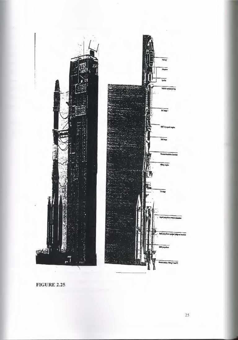
FIGURE 2.25
25

CHAPTER3 DIGITAL COMMUNICATIONS & MULIPLE ACCESS
3.1 IntroductionThe term digital communications covers a broad area of communications techniques,
including digital transmission and digital radio. Digital transmission is the transmittal of
digital pulses between two or more points in a communications system. Digitai radio is
the transmittal of digitally modulated analog carriers between two or more points in a
communications system. Digital transmission systems require a physical facility
between the transmitter and receiver. such as a metallic wire pair, a coaxial cable, or an
optical fiber cable. In digital radio systems, the transmission medium is free space or the
earth's atmosphere.
Figure 3. 1 shows simplified block diagrams of both a digital transmission system and a
digital radio system.
'i' c: I!.':'.= ..rı..JL-r1.. T T .,.-ı_rı_n_ ~...!. .....ını-ı... I t Q ••• ea- .•• . -..ı,pvt
~ ·~-lıNlon, ":". '~ .r,__r-ı_n_ ::.I I
~ca,.k •• -oda4oıbl.: --c,,ptk: •• ··~_..... :-·- ı· ·ı -·--- '" " .ı.,n..._fcıın
--..._r· l"-==~"··ı r1....ıL ~ ~ rLrL1--~-1 J'. . ..0•••••• I O l; 0
.,..,...-- ~ I ~ _rı_nn .,._.._..._•~ • T ~':'~,- 1:' ~
t '.I I
. -:z_ •-: er> !,.,___ . h=~ C ~··Son ; ~=..~..,.,.., (,...J,,..,o.ı.•..~•ı I m \ ~ ·-=-\o;,,,,.,., I ....,...,.
...f""'. ~ - ~ ~ :. n ...rt. -rt- .._rı
FIGURE3.1
3.2 Digital RadioThe property that distinguishes a digital radio system from a conventional AM, FM, or
PM radio system is that in a digital radio system the modulating and demodulated
signals are digital pulses rather than analog waveforms.Digital radio uses analog carriers
26

3.3 I?REQUENCY AND TIME DIVISION MULTIPLEXING
3.3.1 FDM Systems
Much of the earlier development and usage of a satellite links was concerned with
telephony in which the analogue voice channels were multiplied using FDM techniques.
FDM is still very widely used and Figure (3 .2) shows the basic blocks making up the
earth station transmitter and receiver circuits when employing FDM.
just as conventional systems do. Essentially, there are three digital modulation
techniques that are commonly used in digital radio system
Frequency shift keying (FSK), phase shift keying (PSK), and quadrature amplitude
modulation (QAM).
27
loooo--- o .MultJplexer ~tno Uo..conveıter
CompositeFOMmuHlplned r FMout:rMıt.signıl, ı.g. 900dıınntılt, •botıC70MHt.bfndwidth J08 kHt to 4.028 MHZ berıctwidtf1
c..;;......ı 52-eeMI-Lt
p.....,,ımollfiw
ıno,.,t:irdividuılrl9nol.,_.... ll!ANSMITTER UPUNK
70MHıe,ırrie< 6 GHı: microw•\'euofoık carrier '.
: !'t
~:-··~·T ,-~--inoMdo.. CorrıposiıeFOMthınnetı multıpl••edsignal
70MH.t1F ,- -_- _ -:_-_J Down-c;:ooYCf"Cer
Transistoramplifier
-----·
=ı70MHı: FM modulatedcanief'. bandwidth Sc-00 MHı: 4GH:rlout
oscillııııor
C REC£1VEl1OOWNUNK ]
FIGURE3.2
3.3.2 TDM Systems
Figure (3.3) illustrates the basic principle of the time division multiplexing of signals.
The channels carrying different signals are sampled in turn on a regular respective basis
and only during the sampling instants is given channel connected to the common
transmission medium. In this way the channel samples can share the common medium
on a time basis . The channel samples are interleaved and transmitted as a sequence of
pulses-each pulse representing the signal of a given channel at instant of sampling.

6
For successful operation of a TDM system, exactly the same criterion applies as in
PCM/PAM. 'The number of samples per second for all channel signals must be at least
twice the maximum frequency contained in the signal, i. e.
- Sampling frequency = 2x maximum frequency in signal. - For example, for voice
channel band limited to 4 kHz Sampling frequency = 2x4=8 kHz
- For video Channel, band width 5 MHz, Sampling frequency 2x 5 =10 MHz
The samples are organized into frames, one complete frame containing one sample fromeach channel.
In a practical system a frame would also contain synchronizing pulses to ensure that
multiplexers remain synchronized so that the samples, after propagating through thecommon medium are routed
Mulliplıncer Demull1plexar
Chınnel1
3
lrınım~;'.7:,~\.---------.t
J
4
Ch•nnl!ll 1
5
SımploemplUudı
._.__1s\ hıme..-ı--1-.-2nd Ieame ..:.....- 1.......,.._Jrd fq,'me-..-1
:1 4 : ~ J : 3 s:~ ı~nnn n\ I nııtını! L_~ Time
Sımpff!s tn,nımlıted for chenmıl t signal
(b} Each cf,•nnt,I $tımpled In lurn oN tt!gulttr b:ısiır.S8~plı1t11 shtJr9 common fransmb,IJN med;vm on limt!fba!ls. Mulıiı,re"erldemulılplexrtr mu"§I be s--yııdıton;scdre ensurewı,mplfl6•r• fr-ecAed to flırıir rfSfJ~ctivecl,onntrl r:le.sıln~llon
Strımte fDM systom
FIGURE3.3
to their respective channels outputs. The frame time T1and the sampling frequency fsare related:
TrVfs
For example , for speech where fs 8 kHz, the frame time:
Tı= 118000= 125 msec.
28

3.4 MULTIPLE ACCESSES
3.4.1 Introduction
Multiple access is the ability for a large number of earth stations to simultaneously
interconnect their respective communication channels, e.g. voice, data, or TV, using a
given satellite, Multiple access provides the means by which the very wide geographical
coverage capability of a satellite may be more fully exploited and its capacity optimized
for a much greater and wider variety of different users.
There are essentially three multiple access techniques:
1- Frequency Division Multiple Access (FDMA).
2- Time Division Multiple Access (TDMA).
3- Code Division Multiple Access (CDMA).
FDMA and TDMA systems are widely employed by commercial users; CDMA ıs
almost exclusively used by the military.
In FDMA, all users may utilize the satellite at the same time, but access it using
different frequency carriers. In an FDMA network, see Figure 3.4, each station is
assigned at least one carrier frequency and a specialized bandwidth may be allocated
several carriers whilst light traffic stations may employ only one. Each station
modulates its carrier (s) with its traffic signals and this information is transmitted via the
satellite to every station in the network. Filter circuits in the earth station receiver
circuits select the wanted carrier signals and reject all others.
looao- o r
Muftloı'eur ~tar UD-ctınv.nerComı,<W'4 FOM,n.,11iplexed FMOU1l)V(.ıign•I,a.g.900dıtooets. tbcxıt70MHı.bıı~J081d-lt!04.028MH% ı,,..-,
- _.:;;·,1 I S2-UMHz
p,,_..ımoHfiw
lllAHSMITTERUPUNI( 70MHıdlni.r d GH..ı: mienh¥a"'euoıintcarriff ': ~
I
t
m N r··-···ı o Fl Tn""'""'o.,,,.,ıripluor o-o.ıuı.ıo< ~~=: I =..,, ,mpıır..,
°"'- t 70 MHıFM mod<JiıtednJiMdoıl Comı,os.he FOM c::ırrl.-r. b•ndwidttı 5.-88 Mttt 'G~ ~thırwwu ınuftJP'4ıır:.dsi9nat oscıllator
FIGURE 3.4
29

30
'Each TDMA frame contains a reference burst to establish an absolute time reference for
the network and a series of traffic bursts. One for each station. Each of the individual
traffic bursts contains a preamble. Which contains synchronization and signalling
information and identifies the transmitter. And this is followed by the message bits. The
individual bursts are amplified by the satellite transponder and retransmitted in the
down link beam, which is received by all stations in the network. The stations can then
select and extract the signal information destined for them.
In code Division Multiple Access, also referred to as Spread Spectrum. Multiple
Access, the earth stations in the network transmit continuously encoded signals, spread
in frequency, but occupying the same frequency band. Each station is allocated its own
transmissio~ code, and transmission between any pair is effected by the transmitter
station modulating its carrier with the correct code allocated to the destination station.
Afb+stations receive the combined coded transmissions from the satellite and use
decoding techniques to extract the signal addressed to them. For example, Figure 3. 5
demonstrates a frequency hopping CDMA scheme. Each station in the network
transmits with a given pseudo-random frequency pattern, maintaining a carrier
frequency for only a very short time, normally the order of a bit time before hopping to
another one in the coded sequence ..
At present CDMA is not being used in commercial satellite links, but is employed by
the military for interconnecting small groups of mobile stations.
FrequencyOrder or I-bit time- -
Pseudorendom !equonce foreach ol four sıatlons
_L~~~~~~~~~~~---Tlme
FIGURE3.5

3.5.2 BLOCK DIAGRAM or FDM AND TDl\ıl
Ch•nn11ı1
Oe,rıulılpht><tırMulılple,o:ef ________..,....~---~ Con-ırno11H•r1tınlsılo11 m1trHVm,e.g-.••temıe 11,ık,. tefuuıri•I L..-.------'mk:towav~. s:ubm•rln• cıbl•,co•tc:lıı1topllc;ı1 Ubt•
_ Prlncip/,, of mul(ipfıudng: U6tJof ı, con1mcn nıııdlum lo ,,...nsmilSf!IV'ftral~lgnaf chıırmel~ sımuııeııeoustv
Figure 3.31
~~--$lt,,•ıı4.:t " •••••• M-69 "'-'--ıııı.tı,u,,...,
tı--p•nrı., ••.• ,ıı,~111+1,
l'igurc 3.32
Calll!r"o icesignal
Ch~nnı,Igıı:te-ı
Hybridtransformer
n
~eceivedvoicecuıcvt
TflANSMIT
Channelgates
RECc!VE ·Chann.ıgating pulses
FIGURES 3.6 & 3.7
Framealignmen~siçna;
t
'••
Ouantiıerplu!.eneocer
Oigiıalcombiner
s;gn,iııforı
31
Transmitclock. Signallir
intö rmat
Timingrecovervc:

---------------One· fı eme: I2S ıısec ....,_
s 11 1 ıı Is 1,o 111112113114115p s111pıı 1,s12012 ı12212312.ı1a12012112012s13o13, 1.-------------- ~limo ılolı 1-15Voice chıınnels
Time ıloı, 17-31Voice channels
lııuıoı OrılnfremeJınmentiormellon11111)
Tlmsslol 16c11rrles slonıılllnulntormaucn (8 bltsl
30 voice ctıennels uch carrying 8 blls coding 2• (256) amplitude levels1111111.LJ- -BIi stet, 488 nsec
lı,dividual channel lime slotı 25132- J.90025 µsec
Euch lr•m 1 conslsls ol J2 chorınel• numlıerud O lo JI£•clı cl,91rnol ·1a11,µlocf8000 ılmes/ıec, givl11gıı fronıo ı hue
ol ııeooo sec - 12s µne'lime ıloı ·'oreech channel - 125/32- 3.9 µıecEech charı ,et ılol comprises B blıı. so i.,11 ılme slot
ls.J.90613 µsec - 468 nsecGross bil reıe lı
Channels >< Semples/sec x 8 bits -32 x 8000 x e - 2.048 Mblı/sec
Freme stnrcture for JO-channel TOM-PCM system (CC/TT A-lowysrern, recommendation G732.
FIGURE 3.8
u , ••, ••..,,. ••n_,;h•nnel lnpvt
Ptirn11ry PCMmultiplt!:ıt.
JO~Second..orderdigitalmultiplex,120voicı,channel$Primary PCM
multiplex.
JO~
120PCMrnu!ılpraxedtelı,pllomıchannels
3()
Primary PCMmoıtiplex,JOchınn•ls
. {j2JOchacınels
JO
Fimorder(prlmıry)digiıalmuttiplex
Se-condorderdigiuıtmultiplex
Thirdorderdigitalmultfplex
fourthorderdlgiıatmultiplex
Rhhordecd;gitatmuUioltx 56-0
768
Each charın~64kbitlte:c
2.048 Mbitls&c(120ctııı.nnelsl
9.448 Mbit/see(480 channe/JJ
34.368 Mb;u,ocl19Z0chan~sl
JJ9.4 MbiVsec11920 ct,annelsJ
(b} Multiplı,xing /ı,ye/s of TOM~PCMl:i,,rarchies
FIGURE 3.9
32

)-108kl-ltınowitl!h
Sı:ıc.:ınd ~roupcattler. 468 XHt
FIGURE3.10
Fir~t sucer group:5 x ı ı -60 menner~Sarıdwidıh 312-552 kHı
Second $Up~rgrovocar,,er
60 cbarıııeıs
l gro,un - ı ı.. or,•rsr>Qıııl ,up,r 9roup • 5 group,ı - 60ch•n"els
1S ,uper groups - 900 chıınnels - 1 M;ısıu Gıoup
Arsr.,upergroup c.,rrier
Modu!aıo,
Modul•tor
Modul.Jıor
Fi~oı?,.;ıhsunugroup carrier
1-- -------~-~
60~
Ono CCIIT MH1<Group carrier15-"ô-O • :100 er-.=Janowicıtı JOO~
.•.c
33

CHAPTER4 SPACE TRANSPONDER
ı.ı INTRODUCTION
::::ommunicationssatellites are designed to have an operating life time of 5 to 1 O years. The
operator of the system hopes to recover the initial and operating costs well within the
expected life time of the spacecraft, and the designer must provide a satellite that can survive
he hostile environment of the outer space for that long. In order to support the
ıommunicatiorıssystem, the spacecraft must provide a stable platform on which to mount
he antennas, be capable of station keeping, provide the required electrical power for the
.ommunication system and also provide a controlled temperature environment for the
ıommunicationselectronics. In this chapter we discuss the sub-systems needed on spacecraft
o support its primary mission of communications. We also discuss the communications sub
ıystemit self in some detail, and other problems such as reliability.
t.2 SPACECRAFT SUBSYSTEMS
[he major sub-systemsfor spacecraft are as following:
t.2.1 Attitude and Orbit Control System (AOSC)
[his sub-system consists of rocket motors that are used to move the satellite back to the
.orrect orbit when external forces cause it to drift off station and gas jets or inertial devices
hat control the attitude of the spacecraft.
ı, Attitude Control
[he attitude of a satellite refers to its orientation in space. Much of the equipment carried
ıboard a satellite is necessary, for the purpose of controlling its attitude. Attitude control is
ıecessary, for example, to ensure that directional antennas point in the proper directions. In
he case of earth environmental satellites, the earth - sensing instruments must cover the
·equired regions of the earth, which also requires attitude control. A number of forces,
·eferred to as disturbance torque's, can alter the attitude, some examples being the
34
gravitational fields of the earth and the moon, solar radiation, and meteorite impacts.
Attitude control must not be confused with station keeping, which is the term used for
maintaining a satellite in its correct orbital position, although the two are closely related.
Controlling torque's may be generated in a number of ways. Passive attitude control refers
to the use of mechanisms which stabilize the satellite without putting a drain on the satellite's
energy supplies; at most, infrequent use is made of these supplies, for example when thruster
jets are impulses to provide corrective torque. Examples of passive attitude control are spin
stabilization and gravity gradient stabilization. The other form of attitude control is active
control. With active attitude control there is no overall stabilizing torque present to resist the
disturbance torque's. Instead, corrective torque's are applied as required in response to
disturbance torque's. Methods used to generate active control torque's include momentum
wheels, electromagnetic coils, and mass expulsion devices such as gas jets and ion thrusters.
The electromagnetic coil works on the principle that the earth's magnetic field exerts a
torque on a current carrying coil, and that this torque can be controlled through control of
the current. However, the method is of use only for satellites relatively close to the earth.
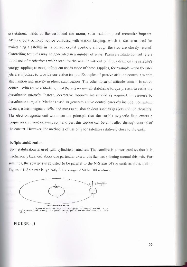
lı, Spin stabilization
Spin stabilization is used with cylindrical satellites. The satellite is constructed so that it is
mechanically balanced about one particular axis and is then set spinning around this axis. For
satellites, the spin axis is adjusted to be parallel to the N-S axis of the earth as illustrated in
Figure 4.1. Spin rate is typically in the range of 50 to 100 rev/min.
G,ec:,."$t:;ı1:ionnry ort:ıi"[
Spin stabiliz.at:ion in t.OE:g eo e ce t.ı o rı cov ort,; c. "Theepin a.xis lies along the pitch .ax!s, -pa r a.f LeI lot.he· e::ı~th·s N-S,a___·~js_ -
FIGURE 4. 1
35

.------..-ELEN'IE'TAYA!"\:D CO.frı..'itA.O.NOA~,-E.Nr.ı,,:....
In the absence of disturbance torque's, the spinning satellite would maintain its correct
attitude relative to the earth. Disturbance torque's are generated in a number of ways, both
external and internal to satellite. Solar radiation gravitational gradients and meteorite,
impacts are all examples of external forces, which can give, rise to disturbance torque's. The
overall effect is that the spin rate will decrease and the direction of the angular spin axis will
change. Nutation, which is a form of wobbling can occur as result of; the disturbance
torque's and I or from misalignmentor unbalance of the control jets. This Nutation must be
damped out by means of energy absorbers known as Nutation dampers.
A.N"'l''ENNA. •REFLEC'T<>A ------------<
TH.ERIVIALA.ADI ATOR ----1
PROPEl.LA.N'TTANK,.<t
t I
. i ı : r : ~ ;i!,,;,~,~t:
FIGURE 4.2
Figure 4.2 shows the Hughes Hs 376 satellite in more detail. The antenna sub-system
consists of a parabolic reflector and feed horns mounted on the despun itself, which also
carries the communications repeaters (transponders). The antenna feeds can therefore be
connected directly to the transponders without the need for radio-frequency (RF) rotaryjoints. While the complete platform is despun.
36

c. Three-axis Stabilization( Body Stabilization)
In three-axis stabilization. as the name suggests, there are stabilizingelements for each of the
three axes, roll, pitch, and yaw. Because the body of the satellite remains fixed relative to the
earth, three-axis stabilization is also known as body stabilization. Active attitude control is
used with three-axis stabilization. This may take the form of control jets (mass-expulsioncontrollers ) fired to correct the attitude of the satellite.'Reaction wheels can also be used. A
reaction wheel is a fly wheel which is normally stationary but reacts when a disturbance
torque tend to shift the spacecraft orientation, by gathering momentum until it absorbs the
effect off the disturbance torque. In practice various combinations of wheels and
mass-expulsion.devices are used Figure (4.3).
Roll/yaw Pitchcontrol thruners
Roll
Directionof flight
tDcwn
Ro\\ woee ı
Yaw w-heeldesaturation
electromagnet
desaturationthrusters
lb) (cl
FIGURE 4.3
37

d. Orbit Control
For communications satellite to accomplish its rnıssıon, it must first acquire and then
maintain its specified orbit with in close limits. The orbital perturbations which make
subsequent corrections of the parameters of the orbit necessary. The final stages of the
launching process and all of the in service orbital corrections are carried out by firing
thrusters on board the satellite in appropriate directions to obtain the desired incremental
velocity vectors. While the satellite is on station and operating, it must also be correctly
oriented, so that its antennas and its solar arrays can function as intended; this orientation of
the satellite attitude in space also facilities the adjustment of the orbital parameters. In order
to maintain the satellite orbit inclination at zero, the gravitational forces due to the Sun and
the Moon should be counteracted by the North-South Station- Keeping (NSSK) propulsion
system,which provides thrust to the north or the south at the appropriate phase of the orbit.
The inclusion of the NSSK system and its fuel on board a satellite carries a mass penalty,
which can be as high as 15 percent of the spacecraft mass when conventional hydrazine
technology is used; the penalty may be even larger if a very long life time in orbit is foreseen.
Utilization of an electric propulsion system can reduce the mass penalty to about 7 percent
for a 7-year geo-stationary orbit mission. The forces arising due to the triaxiality of the
Earth and solar radiation pressure act along the plane of the orbit, resulting in a relative east
west satellite motion. operating thrusters in easterly or westerly direction can provide a
correction. The propellant mass required for east-west station keeping is normally in range
of 3 to 1 O percent of the mass of the satellite, depending on the satellite configuration andthe correction strategy employed.
4.2.2 Telemetry, Tracking, and Command {TT&C)
This systems are partly on the satellite and partly at the controlling earth station. The
telemetry system sends data derived from many sensors on the spacecraft, which monitor the
spacecraft's "health"via a telemetry link to the controlling earth station. The tracking system
is located at this earth station and provides information on the range and the elevation and
azimuth angles of the satellite. Repeated measurement of these three parameters permits
38
computation of orbital elements, from which changes in the orbit of the satellite can be
detected. Based on telemetry data received from the satellite and orbital data obtained from
the tracking system, the control system is used to correct the position and attitude of the
spacecraft. It is also used to control the antenna pointing and communication system
configuration to suit current traffic requirements, and to operate switches on the spacecraft.
Telemetry, tracking and command (TT &C ) systems support the function of spacecraft
management. These functions are vital for successful operation of all satellites and are
treated separately from communication management. In communication satellites the TT&C
system is normal independent of the payload. An Omni-directional antenna provides the
necessary coverage for telemetry and command information to be exchanged between the
ground and the satellite irrespective of the attitude of the latter.
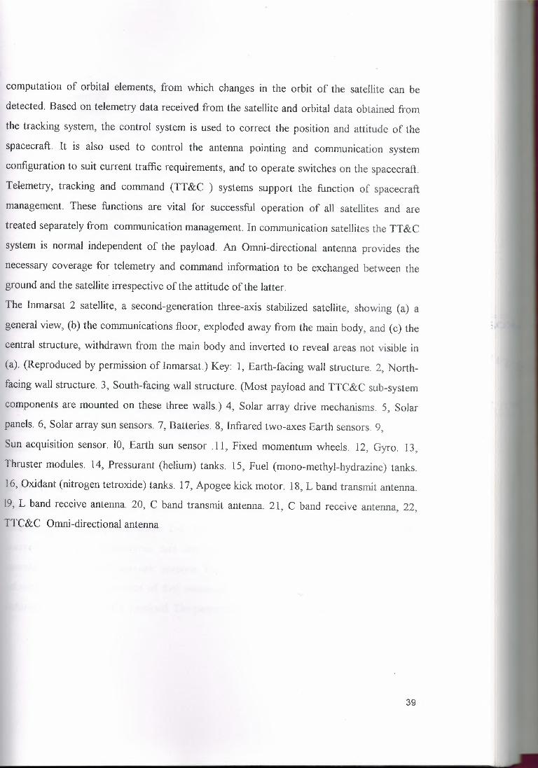
The Inmarsat 2 satellite, a second-generation three-axis stabilized satellite, showing (a) a
general view, (b) the communications floor, exploded away from the main body, and (c) the
central structure, withdrawn from the main body and inverted to reveal areas not visible in
(a). (Reproduced by permission of Inmarsat.) Key: 1, Earth-facing wall structure. 2, North
facing wall structure. 3, South-facing wall structure. (Most payload and TTC&C sub-system
components are mounted on these three walls.) 4, Solar array drive mechanisms. 5, Solar
panels. 6, Solar array sun sensors. 7, Batteries. 8, Infrared two-axes Earth sensors. 9,
Sun acquisition sensor. 10, Earth sun sensor .11, Fixed momentum wheels. 12, Gyro. 13,
Thruster modules. 14, Pressurant (helium) tanks. 15, Fuel (mono-methyl-hydrazine) tanks.
16, Oxidant (nitrogen tetroxide) tanks. 1 7, Apogee kick motor. 18, L band transmit antenna.
19, L band receive antenna. 20, C band transmit antenna. 21, C band receive antenna, 22,
TTC&C Omni-directional antenna
39

The Main Function Of a TT& C System are to
a. Monitor the performance of all satellite sub-systems and transmit the monitored data to
the satellite control center;
b. Support the determination of orbital parameters;
c. Provide a source to earth stations for tracking ;
ct. Receive commands from the control center for performing various functions of the
satellite .
:ı
-22
FIGURE 4.4
a. Telemetry Sub-System
I'he function is to monitor various spacecraft parameters such as voltage, current,
emperature and equipment status and to transmit the measured values to the satellite
.ontrol center. The telemetered data are analyzed at the control and used for routine
ıperational and failure diagnostic purpose. For example, the data can be used to provide
nformation about the amount of fuel remaining on the satellite. A need to switch to a
edundant chain or an HP A overload. The parameters most commonly monitored are:
40

41
Voltage, current and temperature of all major sub-system;
Switch status of communication transponders;
Pressure of propulsion tanks;
Outputs from attitude sensors;
Reaction wheel speed.
igure 4.5 shows the main elements of a telemetry sub-system. The monitored signals are all
ıultiplexed and transmitted as a continuous digital stream. Several sensors provide analog
gnals whereas others give digital signals. Analog signals are digitally encoded and
ıultiplexed with other digital signals.
Digital outputs
~
Ranging signal
~Sensoroutputs
AIDconverter
formattor Modulator
Telemetrysional
FIGURE 4.5
vpical telemetry data rates are in the range 150 -100 bps. For low- bit rate telemetry a sub
rrier modulated with PSK or FSK is used before RF modulation. PSK is the most
ımmonly used at RF. The telemetry signal is commonly used as a beacon by ground
ıtions for tracking. Distributed telemetry systems are increasingly being, favored. In this
mfiguration, digital encoders are located in each sub-system of all the satellite and data
ım each encoder are sent to a central encoder via a common, time-shared bus. This
heme reduces the number of wire connections considerably. This type of modulator

design also permits easy expansion of the initial design and facilities testing during assembly
of the satellite.
b. Command Sub-System
The command system receives commands transmitted from the satellite control center,
verifies reception and executes these commands. Example of common commands are:
• Transponder switching
• Switch matrix configuration
• Antenna pointing control
• Controlling direction speed of solar array drive
• Batteıy reconditioning
• Thruster firing
• Switchingheaters of the various sub-system
Typically, over 300 different commands could be used on a communication satellite. From
the example listed above, it can be noted that it is vital that commands be decoded and
executed correctly. Consider the situation where a command for switching off an active
thruster is mis-interpreted the thruster remains activated the consequence would be
depletion of station keeping fuel and possibly loss of the satellite as the satellite drifts away
from its nominal position. A fail- safe has to be achieved under low carrier-to- noise
conditions (typically 78 dB). A commonly used safety feature demands verification of each
command by the satellite control center be execution. To reduce the impact of high bit error
rate, coding and repetition of data are employed . further improvements can be obtained by
combining the outputs of two receive chains. The message is accepted only when both
outputs are identical.
42

Command Verification corndecoder ı----- process exec
Vcrifıcation
I I .
data
Commandreccıver
mand•...utıon
Rangıng
Base band] To telemetry
TransmitterExtraction------------~
FIGURE 4.6
Figure (4.6) shows the block diagram of a typical command system. The antennas used
during the orbit-raising phase are near Omni-directional to maintain contact for possible
orientations of the sat. During critical maneuvers. The receiver converts RF signals to base
band. Typical bit rate are I 00 bps. A command decoder decodes commands. This is
followed by a verification process which usually involves the transmitter of the decoded
commands back too the sat. control center via the telemetry carrier. The command system
hardware is duplicated to improve the reliability . The command is stored in a memory and is
executed only, after verification. The Tele-command receiver also provides the base-band
output of ranging tone. This base band is modulated on the telemetry beacon and transmitted
back to the satellite control system.
c. Tracking Satellite Position
To maintain a sat. ln it's assigned orbital slot and provide look angle information to earth
stations in the network it is necessary to estimate the orbital parameters of a sat. regularly.
These parameters can be obtained by tracking the communication sat. from the ground and
measuring the angular position and range of the sat. During orbit raising when the sat. is a
non-gee-stationary orbit, a network of ground stations distributed through out the globe is
43
'ı

used for obtaining the orbital parameters. The most commonly used method far angular
tracking is the mono-pulse technique. Angular positions measured though a single station
taken over a day are adequate for the determination of orbital parameters. The range of a
sat. can be obtained by measuring the roundtrip time delay of a signal. This is achieved by
transmitting a signal modulated with a tone. The signal is received at the spacecraft and
modulated in command receiver, the tone is then re-modulated and transmitted back to the
ground on the telemetry carrier. The time delay is obtained by measuring the phase
difference between the transmitted and received tones shows the main blocks of a multi
tone ranging system. In practice, the phase difference between the transmitted & received
tones can be more than 360°, leading to errors in multiple tones of tone time period. To
resolve the ambiguity, multiple tones are transmitted . Lower frequencies resolve the
ambiguity and the high tone frequencies provide the desired accuracy. Consider a total
phase shift in degrees <D>360°:
<I> = 360 n + ~<I> where n= unkown integer~<I> = measured phase shift
• The range of R is then given byR = ı... n + (~$/ 360°).A. , where A.=wave length
Stable reference Tone Transmitter
~source ~ generator-;
,ı,Phase coınposition Fromand data processing receiver
Range
FIGURE 4.7
44

ıl. Low -Noise Amplifiers (LNA)
The satellite and the earth station receivers are handling very low level signals. We have to
put a (LNA) low noise amplifier to do amplification for signal without amplifying the noise.
e. High-Power Amplifiers (UPA)
The high amplifier is a wide band device (500 MHZ to 6 GHZ) and it carı be used lo amplify
a number of carriers within that bandwidth although if more ılıan one carrier is used the
output power must be reduced in order to inter-modulation effects.
Low noise amplifier Frequency range Typical noise temp, Comments(GI iz) (K)
Parametric amplifier 3.7-4.2 30 Thermo-electriccooled l 1-12 90 coolingParametric amplifier 3.7-4.2 40 Temperature ofuncooled 11-12 JOO enclosure controlled
Thermo clcctricallvGtı\s FET cooled 3.7-4.2 so Typically, first stage
11-12 125 GaAs FET cooledThermo- clectricallv
Gı.ı\s FET uncooled J.7-4.2 75l l-12 170
f. Down-Converter
It is change High frequency lo Low value. In our transponders we use down convener lo
reduce the output frequency froın LNA lo Suitable frequency.
g. Up-Converter
lt does the opposite function of down converter. lt convert Low frequency lo High
frequency.
h. Band Pass Filter
This filler used for limits the signal and it's characleristics diagram Frequency Bandpass
Filter characteristics as shown in figure.
45

Frequency
sertion loss (dB)
FIGURE 4.7 B.P.F
t2.3 Power System
ı\11 communications satellites derive their electrical power from solar cells. The power is
.ısed by the communication system, mainly in its transmitters. and also by all other electrical
systemson the spacecraft. The latter use is termed housekeeping, since these sub-systems
serveto support the communications system.
t2.4 Communications Sub-Systems
The Communications Sub-Systems is the major component of a communications satellite,
md the remainder of the spacecraft is there solely to support it. Frequently, the
communicationsequipment is only a small part of the weight and volume of the whole
spacecraft.It is usually composed of one or more antennas, which receive and transmit over
wide bandwidth at. microwave frequencies, and a set of receivers and transmitters that
unplify and transmit the incoming signals. The receiver-transmitter units are known as
ransponders.
t2.5 Spacecraft Antennas
Although these form part of the complete communication system, they can be considered
separatelyfrom the transponders. On advanced satellites such as INTELSATV, the antenna
46

systems are very complex and produce beams with shapes carefully tailored to match the
areas on the earth's surface served by the spacecraft.
4.3 The Electrical Power Supply
4.3.1 Energy Sources And Power Systems
The power requirement of a geo-stationary satellite may be as high as 5 kW. most of the
communicationspayload. The supply of electric power in a spacecraft involves several basic
elements. There must be a primary source of energy and means for converting that energy
into electrical energy. A device is needed for storing the electrical energy to meet peak
demands and to provide power during eclipses. Finally a system is required for conditioning,
regulating and distributing the electrical energy at the required levels.
Only two primary sources are suitable for missions with life times in space measured in
years, namely radiation from the sun and the spontaneous decay of radioactive material. The
radioactivity option is preferred where the power requirement is high, perhaps 1 O kW or
more, or when an interplanetary mission takes the spacecraft too far from the sun. But solar
radiation, converted to electrical power by an array of photo voltaic cells, is always chosen
for Earth satellites used for telecommunications. Rechargeable batteries are used for storing
electricalpower during the sunlit portion of the orbit., to provide power during eclipses and
at peak demand periods. A simplified diagram of a typical satellite power sub-system is
shown in Figure 4.8. primary electrical power is generated by the main solar panel and it is
supplied to the power utilization loads through the main distribution bus. Bus voltage
limiters ensure that bus voltages do not exceed the maximum voltage rating of the
consuming sub-systems.Limiter resistors energized by the bus load limiters provide variable
shunt loads to stabilize the bus voltage when the solar panel output voltage rises or the
power utilization loading decrease. The spacecraft batteries charge I discharge control
functions are provided by a battery controller device. When the distribution bus voltage is
reduced to a predetermined level due to decreased solar panel output, the battery discharge
regulator is activated to provide a minimum regulated bus voltage from the battery. The
47

20-3G VPC
battery voltage needs to be greater that the bus voltage for two main reasons. The discharge
regulator has certain impedance, causing a voltage drop across its terminals. And the
maximum battery voltage required for full recharge is considerably higher than the battery
discharge output voltage. Usually a small area of solar paııel connected iıı series with the
main panel provides the required recharging voltage boost and limits the maximum recharge
current. This simplifies the charge control functions of the controller to the simple on- off
and rate chaııge switching shown in Figure 4. 8
Solarpanel lorbattery
ctuırging-r-
Malıı
FIGURE 4.:s,
tII
V
PJGURE 4.9
4.3.2 Solar Cells
A solar or photo-voltaic cell converts incident solar radiation into electric energy by the
48

photo-voltaic as illustrated in Figure 4. 9. The current versus Voltage characteristics of a
solar cell. When it is dark is shown in Figure 4.10. The curve of the non- illuminated solar
cell indicates that it behaves as a power sink like any other semiconductor diode; its
resistance is low when the current flows in the forward direction and high wlıen if flows in
the reverse direction. When the solar cell is illuminated, incident photons are absorbed,
ıonızıng the atoms of the semiconductor material and producing electrons I hole pairs.
Electric current is generated when the electrons & holes reach the junction beforerecombining.
Power sourcequadrant Power sink
quadrantiI
I Diode
op'¢J'. n U i Vo
,,/
/
---·-----·---·-·-~~,¥-------·/.-------v-
Dark J _,----1-llu-,~;;;L;d
Powersinjquadrant Power source
quadrant
Ji'lGURE 4.10
Maximum powerp.oint
FIGURE 4.11
Illumination results in the voltage I current curve being shifted in the minus-current direction
in proportion to the strength of the incident illumination. The characteristic I /V output
49

graph shown in Figure 4. 11 is obtained by inverting the power source quadrant of Figure 3.
1 O. The output voltage of a silicon cell under typical load conditions is about 0.5V.
The solar cells of a gee-stationary satellite may be cycled in temperature between 1 1 O and
340 K. The efficiency of solar cells reduces with increasing temperature, so their
temperature has to be kept as low as possible in order to obtain the maximum power output.
The variation of efficiency with temperature for gallium arsenate, germanium and silicon
solar cells is shown in Figure 4. 12. The efficiency of solar cells in space also decreases with
the passage of time. This is due to the damage caused to the cell semiconductor material,
due mainly to solar flare protons and the trapped electrons of the Van Allen radiation belts.
Typically, the power output is reduced by 1 O per cent in the first years. Placing a glass cover
over each solar cell considerably reduces radiation damage caused by the lower- energy
particles. The amount of radiation failing on the cell is reduced as the thickness of the glass
employed is increased. However, the cover glass also acts as a filter, which reduces the total
energy absorbed by the cell, thus reducing its operating temperature and diminishing
somewhat the loss of power output caused by the presence of the cover. The cover glass is
usually made of quartz, sapphire, or silica doped with cerium.
20
~ga,
"OEw
10
FIGURE 4.12
4.3.3 Solar Arrays
The power output of a single solar cell is very low and the individual cells must be
50

connected in a series- parallel matrix as shown in fig. 4~ 13 to satisfy the voltage, current &
power requirements of the space-craft. The solar cell matrices are mounted on light weight
honey comb or fibre-glass substrates to form solar arrays. Satellites utilize either dual-spin or
three-axis attitude stabilization. In the dual-spin configuration ılıe spiııniııg druınis covered
with solar cells. ln the three-axis stabilized configuration cells are mounted on deployable
flat panel appendages which are continuously oriented to obtain maximum exposure to solar
radiation. lnspin-stabilized satellites the individual cells are usually arranged ııı a
series-parallel configuration of whiclı tlıe series strain can typically vary fronı 66 to 71 cells.
Mo_çiules are constructed with three strings in parallel connected together in series- parallel
network as shown in figure 4. l3(ii). This arrangement minimizes the power loss resultingfrom the failure of a single sell.
A solar array drive mechanism is employed, first to acquire an orbit and tlıen lo track the
sun, maintaining the face of the array approximately normal to the solar radiation as tlıe
satellite moves around its orbit. The drive mechanism also includes means for transmitting
power from the rotating arrays( one revolution per orbit) to the equipment in the spacecraft
body. The deployable solar arrays of the Intelsat Vlll satellite. in the launch and thedeployed configuration, are shown in Figure 4 .14.
(i)
-=-/cc::J- ---,, - . ----;'·--· -- - -'·ı,--=-----'----
L~f,_=ı _ ç·_ı '\.-- f__ f __JL.--1_ I _- -l , L_: I--x=)_ . -_;ı__ - .../\.,- -l.
ı~J -- L~J I,-··'f.- -, r-=";-_IL_' ___f '------ - - ..L·----. ·---==L_ ·[=---ı __ J I_ I
---<.:.--- ·--- -.::--. --(ıı)
FIGURE 4.13
51

Ccnrı nıc rciat Sat ct t ıre (.,"otn,nun:icntinn
Stowan r.ol..ıır;.,ı.rr&)'
(a)
/>··>·-- ..__- ·----~ ~~? _.,?-·-. ----- ..-<-::/'"
üeployed &;.;.:..· "'""'Y-
(t.>)
FIGURE 4.14
4.3.4 Energy Storage
Storage batteries are used to provide power during eclipse and to satisfy peak power
demands, which may be much greater than the average available solar power. In the GS
there are two eclipse seasons per annum, centered on the vernal and autumnal respectively;
each eclipse period lasts for 45 days with a maximum shadow time of 1 .2 hours as shown in
Figure 4. 15 . For satellites in lower orbits, the number of eclipses is greater .
There are many types of storage battery commerciallyavailable but only four namely silver
zinc, silver-cadmium, nickel-cadmium and nickel-hydrogen, have been qualified for space
applicationsto date.
52

JAN.
IIIII
FEB. II MARCH
Ma,cimum ou-anon70 minutes at equina)(
MAY JUNE
NOV. DEC.JULY
FIGURE 4.15
AUGUST J SEPT.
42 days
In general the main requirements of the storage batteries for space application are:
1. To receive and deliver power at high rates. These enables the spacecraft to utilize the
extra power delivered by the solar cells when the satellite comes out of eclipse and to
provide the extra power needed at peak periods.
2. To survive a large number of charge-discharge cycles under various conditions. There are
90 charge-discharge cycles per year in the GSO where the battery is being charged during
the orbital day and discharge during the orbital night.
3. High recharge efficiency.
4. Leakage-free seals, able to withstand a large number of extreme thermal and pressure
changes.
5. Capability of operating in a gravity- free environment in all positions.
6. High usable energy capacity for low per-unit weight and volume.
7. Stability under long-term overcharge conditions.
8. Ability to withstand the stresses of the launch and in -orbit environments
9. High reliability.
1 O. Long life.
53

4.3.5 Power Conditioning And Control
The Power Conditioning And Control System (PCCS.) ensures that the output of the solar
array and the storage battery satisfy the power requirements of the various sub-systems. The
PCCS also controls the battery charge-discharge function. which is essential in order to
maximize the battery life time. In essence. the PCCS is an assembly of various types of
regulators, DC-to-DC or DC-to-AC converters and control circuits.
PCCSs can be classified into two main categories; dissipative and non-dissipative systems
the power requirement of the satellite is less than the output of the solar arrays, the unused
power being dissipated by the system. In non-dissipative systems almost all the power
provided by the solar arrays is used to satisfy the operational needs of the spacecraft.
Dissipative systems can be categorized according to whether the bus voltage is regulated or
unregulated. In general, the different voltage levels and regulation profiles, which are
required at different points of the spacecraft sub-systems differ from the ones, provided by
the bus. The bus voltage therefore needs to be further regulated, increased, decreased or
inverted by utilizingregulators and DC-to-DC and DC-to-AC converters.
4.4 Antenna Sub-System
Directional beams are usually produced by means of reflector type antennas, the
paraboloidal reflector being the most common. As the gain of the paraboloidal reflector,
relativeto an isotropic radiator. is given by
G = nı (1tDl1ı,)2
Where 1ı, is the wavelength of the signal, D is the reflector diameter, and ru is the aperture
efficiencyA typical value for rıı is 0.55. The -3 dB beam-width is given approximately by:
03dB= 70 A ID degrees
The ratio Dl 1ı, is seen to be the key factor in these equations, the gain being directly
proportional to (Dl ıı,)2 and the beam width inversely proportional to Dl A. Hence the gain
can be increased, and the beam-width made narrower. by increasing the reflector size or
decreasing the wavelength. The largest reflectors are those for the 614GHz band.
54
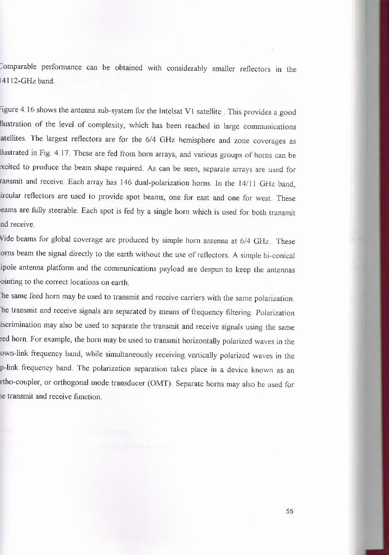
:::omparable performance can be obtained with considerably smaller reflectors in the
l4112-GHz band.
'igure 4.16 shows the antenna sub-system for the Intelsat VI satellite. This provides a good
llustration of the level of complexity, which has been reached in large communications
:atellites. The largest reflectors are for the 6/4 GHz hemisphere and zone coverages as
llustrated in Fig. 4.17. These are fed from horn arrays, and various groups of horns can be
xcited to produce the beam shape required. As can be seen, separate arrays are used for
ransmit and receive. Each array has 146 dual-polarization horns. In the 14/11 GHz band,
.ircular reflectors are used to provide spot beams, one for east and one for west. These
ıeams are fully steerable. Each spot is fed by a single horn which is used for both transmit
rıd receive.
Vide beams for global coverage are produced by simple horn antenna at 6/4 GHz .. These
ıorns beam the signal directly to the earth without the use of reflectors. A simple bi-conical
lipole antenna platform and the communications payload are despun to keep the antennas
ıointing to the correct locations on earth.
'he same feed horn may be used to transmit and receive carriers with the same polarization.
'he transmit and receive signals are separated by means of frequency filtering. Polarization
iscrimination may also be used to separate the transmit and receive signals using the same
eed horn. For example, the horn may be used to transmit horizontally polarized waves in the
own-link frequency band, while simultaneously receiving vertically polarized waves in the
p-link frequency band. The polarization separation takes place in a device known as an
rtho-coupler, or orthogonal mode transducer (OMT). Separate horns may also be used for
ıe transmit and receive function.
55
"

s.c,oorı ,,..,,~ P••• of <tf- •- -r-
I~1.o l"l/"11 o~o,,.,,~ •-,c--,ı-,·-......... •.•. -~ ••• ıı..••••••
I.O..,..(1.1!1' •n>
~-· ·-- -
E M<t:IU,t••••.•ol •• :ııo-- -. ••.••ı •• AOfl
TJ~~ un _ _t..4.!nn.n .su_bYysteı.n !'or the Jııtelso.t VJ sııt.aellit~.
FIGURE 4.16
c=) 614 OH.ı: >-'"'c=.J 6/-4 GHa •o•-:~ !..-4/11 ~·• ~•: alngle-pq,la,l:ııatlon
S..telllıe luc;.aılo,,.3.35,.&,•ı:
FIGURE 4.17
The satellite uses three types of antennas
i. Spot beams dish antennas, steerable antennas to, adjust the area the beam cover on earth,
56

.. -·
ii. Receiving and transmitting earth coverage antennas fixed position, where horn antennas
are used for global coverage.
iii. A non-directional antenna for receıvıng commands to the satellite and transmitting
telemetry data to earth. The data rate use with this antenna is very low, and so its low gain is
acceptable. Wire antennas, which are monopoles and dipoles are used. Figure (4-18) shows
three types of antennas mounted on INTELSAT l V satellites: There are two types of beams,
spot beams & global beams as shown iıı Figure (4 .19)
(.),n •. ı;,ı;,'l"•:f;o:>n.ol ıınt•..-H1,:, ,o, ror<•lvi:ı,g ı::o.rn,.,,.w,d~.- •. ,d ,..-.n,w.mı,ııncı l•l-n,e.ı, v d,0111
\
_ -,-....,ı"' dl•h •nıı.enr,.ıı, .•. SO ;ncrıcs indi••n~ce,· . ..,.,,ch ;nc;ı,-...+dv•llı,,11,...,.,....,.,,ı~. ın•vlng ı,ıı 4.~ ·"q>Ol ~_,,..,
J?IGURE 4 . .ıs
b.
füGURE 4.19
4.4.1 Global lleaııı in Satellite Down-link
Figure (4-20 ) shows the parameters used to calculate the beam-width for a certain coverage
area.
57

'or a global beam of a satellite at a geo-stationary orbit, H=36000Km
.nd a= 63 70 Km . The global Beamwidth can calculated as follows :
l.W/2 = tarı" (a/ H+a)
= tan" (6370/42370) = 9°
l.W = 18° B.W
. Spot Beams in Satellite Down-link:
lpot beams increasing satellite EUUJ by using narrower beams, so as to concentrate power
ıto areas smaller than covered by global beams. In this way the reception of wide band
ıformatiorı in small earth stations with low g/T0 values will be improved. Spot beams
ıcrease CNR within the beam, but reduce the coverage area .
'he transmission technique can be separated by the use of dual polarization within a spot
earn as shown in figure (4.2 I )
Multipleopot benms
Verticalpolaıjzation
(a) (b)
FIGURE 4.21
ome earth stations use only horizontal polarization others use vertical polarization .Some
earnwidth, earth coverage diameter of the beam footprint & effective EIRP (effective
otropic radiation power) are the spot beam parameters where :
IRP = 1 O log( PT Gr)
PT = transmitter power
58

GT = Gain of the transmitting antenna
.t is noted that the ELRP per beam increases as the spot is reduced, but number of spots
ıeeded to cover a fixed area also increases. This have, the disadvantage of using multiple
ıntenna beams from the satellite, increase the complexity & structure of the spacecraft &
ıeam pointing is more critical with the narrower beams. This can be shown in table (3- 1)
ısing the following relation:
an (B.W/2 )=( a/H+ a)
ıVhere, H = 3 6000 Km.
\.=Earth coverage diameter.
l'able-l.Z : Spot Beam Parameters
,pot Beamwidth Earth coverage EIRP (dB)
Diameter00 3921 5.1;,70 2235 9.9:.80 1117 16. 1.Oo 392 . 25.0ı.57° 223 29.9
ı. Multiple Beams:
'here are basic ways to produce multiple beams from a satellite :
. Using of separates antennas for each beam.
. Single reflector or microwave lens using multiple feeds.
. Phased antenna arrays.
. Disadvantage In Forming Spot Beams With Arrays
The size of the array ( number of elements ) becomes large when it is forming a small spot.
. The Beam width decreases with the number of elements of the array. (Narrow spot beam
rrays require an increase in both the array size and the numbers of phase-shift feeder
59
,,,I

elements at the Satellite ).
d. Advantage of Spot Beam
To achieve the advantage of spot beams is by using hopping beams as follows and sketched
figure (4.22). A single spot can be moved in sequence from one point to another. The wide
coverage is achieved with a single beam, but only on a shared time basis. Only one spot
antenna assembly is needed, but must repositioning sequentially, which is achieved by
gimbals control where the antenna assembly is mechanical re-pointed in each desired
direction.
Beam footprintat hop 1
Beam to o tp r+rıal hop 2
,I
'hop 4 tıap 3
FIGURE 4.22
FIGURE4.23
60

s....~m.-n•ı__..,.
~ - . Elnom.,;.: le) ,..,r,ot..;{t.,J 70n<.ıl; !cl O(:'Orth
f?IGURE 4.24
ı.s SATELLITE SYSTEM LINK MODELS
3-ssentially, a satellite system consists of three basic sections: an up-link, a satellite
ransponder, and a Down- link.
t.5.1 Up-Link Model
I'he primary component within the up-link section of a satellite system is the earth station
.ransmitter. A typical earth station transmitter consists of an lF modulator, an lF-to-RF
nicrowave up-converter, a high power amplifier (HPA), and some means of band limiting
he final output spectrum (i.e. an output bandpass filter). Figure 4.25 shows the block
iiagram of a satellite earth station transmitter. The IF modulator converts the input
ıaseband signals to either an FM, a PSK, or QAM modulated intermediate frequency. The
ıp-converter ( mixer and band-pass filter) convert the IF to an appropriate RF carrier
requency .The HPA provides adequate input sensitivity and output power to propagate the
ıignal to satellite transponder. HP As commonly used are klystons and traveling-wave tubes.
To ~totteıtıt.,.t•l'lnaı,ond.,,.
Up-conve•>o• J_...,,--V-: - - -:
B"""b"nd in Modvlotor lF l nr- ;COM o,~ <FM, PSK. -BPF ---C~···' B+f'F ' EJ,,, ...PCMrroM or OAM> t ,. '
[ RF ll :: ~~?ı;~~e(~t~;r !! j
FIGURE 4.25
61

From s~tellitetranspondı:ır
Oowr'l-convortor
ı.ow-ooteeanıplifler Mixer
DemoduloıortFM, PSK.orOAM)
Baaeband outFDMorPCM/TOM
LNA
RF
MW generator4 GHz or 12GHz
Satellite down-link made!
FIGURE4.26
4.5.2 Down-link ModelAn earth station receiver includes an input BPF, an LNA, and an Rf -to- IF down converter.
Figure 4.26 shows a block diagram of a typical earth station receiver. Again the BPF limits
the input noise power to the LNA. The LNA is a highly sensitive, low-noise device such as a
tunnel diode amplifieror a parametric amplifier. The RF-to-IF down- converter is a mixer I
bandpass filter combinationwhich converts the received RF signal to an IF frequency.
4.5.3 Cross-LinksOccasionally,there is an application where it is necessary to communicate between satellites.
This is done using satellite crosslinks or satellite links (ISLs), shown in Figure 4.27. A
disadvantage of using an ISL is that both transmitter and receiver are space-bound.
Consequently,both the transmitter's output power and receiver's input sensitivityare limited
62

Cross-link
\ Up-link/down-link Up-link/down-link rEarth
lntersatellite link
FIGURE 4.27
63

CHAPTERS EARTH STATION
5.1 INTRODUCTION
The earth segment of a satellite communication system consists of the transmit and receive
stations. The simplest of these are the home TV Receiver-Only (TYRO) systems, and the
most complex are the terminal stations used for international communication networks.
Also included in the earth segment are those stations, which are on ships at sea, and
commercial and military land and aeronautical mobile stations.
Earth stations, which are used exclusively for logistic support of satellites, such as those
providing the telemetry, tracking, and command (TT &C) functions, are considered as part
of the space segment.
Definitions
Earth - Orbiting Satellites
· Apogee The point farthest from earth. Apogee height is shown as ha in Fig. 5 .1
· Perigee The point of closest approach to earth. The perigee height is shown as hp in Fig.
5. 1
· Line of upsides The line joining the perigee and apogee through the center of the earth.
· Ascending node The point where the orbit crosses the equatorial plane going from south
to north.
· Descending node The point where the orbit crosses the equatorial plane going from north
to south.
· Line of nodes The line joining the ascending and descending nodes through the center of
the earth.
· Inclination The angle between the orbital plane and earth's equatorial plane. It is measured
at the ascending node from the equator to the orbit, going from east to north. The
inclination is shown as in Fig. 5.2 . It will be seen that greatest latitude, north or south, is
equal to the inclination.
· Pro-grade orbit As orbit in which the satellite moves in the same direction as the earth, s
rotation, as shown in Fig 5.2. The pro-grade orbit is also known 90°. Most satellites are
,1
64

Launched in a pro-grade orbit because the earth's rotational velocity provides part of the
orbital velocity with a consequent saving in launch energy.
FIGURE 5.1
,I
Pr<>9r•deor-bit
_..,
Progrndc u1ıd -r·~tı-ogrn.d-e orbit..°"'.
FIGURE 5.2
· Rectrograde orbit As orbit in the satellite moves in the direction counter to the earth's
rotation, as shown in Fig 5.2. The inclination of a retrograde orbit always lies between 90°
and 180°.
· Argument of perigee The angle from ascending node to perigee, measured in the orbital
plane at the earth's center, in the direction of satellite motion. The argument of perigee is
shown in Fig. 5.3
65

.Mean anomaly Mean anomaly M gives an average value of the angular position of the
satellite with reference to the perigee . For a circular orbit, M gives the angular position of
the satellite in the orbit. For an elliptical orbit, the position is much more difficult to
calculate, and M is used as an intermediate step in the calculation .
.True anomaly The true anomaly is the angle from perigee to the satellite position,
measured at the earth's center. This gives the true angular position of the satellite in orbit as
a function of time.
EquatorA;-.fı::Han"'
FIGURE 5.3
;,2 EARTH STATIONS DESIGN CONSIDERATION
[he design of an earth station depends on a number of factors. Some of these are:
;.2.1 Type of service: Fixed Satellite Service, Mobile Satellite Service or Broadcast
;atellite Service.
;.2.2 Type of communication requirements: telephony , data, television, etc.
;.2.3 Required base-band signal quality at the destination.
i.2.4 Traffic requirements: number of channels, type of traffic continuous or bursty.
i.2.5 Cost reliability: Two broad stages may be identified in the design process. The first
tage is based on the overall system requirements from which the required earth station
ıarameters such as G/T, transmit power, access scheme, etc, and emerge. An earth station
lesigner then engineers the most cost-effective configuration to achieve these specifications.
66
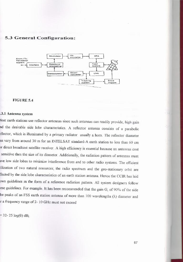
5_3 General Configuration:
Modulato, Upconvertel'
HPA ı::rom/ToTerrestr-i.atsys.tam
lnterfece
Oemodu••to~ Dowl°\converte<
l.,NA
'Tracl,(ing
~Drivemo-ıors
-. ---..______
FIGURE 5.4
:.3.1 Antenna system
fost earth stations use reflector antennas since such antennas can readily provide, high gain
nd the desirable side lobe characteristics. A reflector antenna consists of a parabolic
eflector,which is illuminatedby a primary radiator usually a horn. The reflector diameter
an vary from around 30 m for an INTELSAT standard-A earth station to less than 60 cm
ır direct broadcast satellite receiver. A high efficiencyis essential because an antennas cost
. sensitive then the size of its diameter. Additionally, the radiation pattern of antennas must
ave low side lobes to minimize interference from and to other radio systems. The efficient
tilization of two natural resources; the radio spectrum and the geo-stationary orbit are
fected by the side lobe characteristics of an earth station antenna. Hence the CCIR has laid
own guidelines m the form of a reference radiation pattern. All system designers follow
ıese guidelines.For example. It has been recommended that the gain G, of 90% of the side
be peaks of an FSS earth station antenna of more than 100 wavelengths (A) diameter and,r a frequency range of 2- 1 O GHz must not exceed
= 32- 25 log(O)dBı
67

V'here 8 = off-axis angle with respect to the antenna bore-sight (off-axis angle is limited to
.ithin 3 ° of the geo-stationary arc)
0:::;; 8:::;; 200
'he reference pattern given by equation above was based on the available data of earth
:ationantennas of the 1960s. This pattern has recently been modified to (CCIR), 1986)
i= 29- 25 log(S) dBr
he effect of this change is a reduction in interference caused or received by an earth station.
he main purpose of the change was to increase the effective utilization of the geo
:ationary orbit, effected by a reduction in the interference caused/ received to /from
djacent satellite systems. Thus the improved specification has permitted adjacent spacing to
e reduced from about 3° to~ 2°
or practical reasons the CCIR reference antenna pattern for antenna diameters D , less than
00% is modified to
r= 52- 1 O log (D/)ı.) - 25 log (8) dBi
imilar reference patterns have been suggested for other services such as BSS. Earth
ations can have either axi-syrnmetric or asymmetric (also called offset) antenna
»ıfigurations based on their geometry.
68

Satellite Cornr>ıunicuıio,ıs Sysı,en-,s
Not~ ••homE•ulı
\ rıao!lır~-~ave front
ı4 --~ .ı,1 '••d:- ~·~- o, •••••••.••••••••ı~~A:;~::;;" ~~ ~ ...: Focus.
Mnln ~'- L _retl<eclor -~ ı
Oh-,ctlonof Earth
FIGURE5.5
Oiroction of rn'!ıiolıoıım
r,
FIGURE5.6
---··---·----------
s>• ıor-ro.-ryfood
FIGURE5_7
69

Elevation
7 --=1--- ( ·--:1 .. Vc'Y-axi'$.0
{al lb)
(2) An a.zi.ınuıh-eJevaıion n,ount. (b) Ao .ı,·__y rnounr.
FIGURE 5.8
5.3.2 Feed System
I'he primary feed system used in existing earth stations performs a number of functions.
Depending on the type of earth station, these
unctions may be:
. to illuminate the main reflector;
i. to separate the transmit and receive band;
ii. to separate and combine polarization in a dual polarized system;
v. to provide error signals for some types of satellite tracking system .
i.3.3 Tracking System
'racking is essential when the satellite drift, as seen by an earth station antenna, ıs a
igniflcarıt fraction of an earth station's antenna beam-width .
• Satellite Acquisition
lefore communication can be established it is necessary to "acquire" a satellite. One method
: to program the antenna to perform a scan around the predicted position of satellite. The
utornatic tracking system is switched on when the received signal strength is sufficient to
70

71
:k the tracking receiver to the beacon. In simplest form, a satellite can be acquired by
ıving the antenna manuallyaround the expected satellite position.
Automatic Tracking
:er acquisition a satellite needs to be tracked continuously. The automatic tracking system
en called an auto-track system) performs this function. Auto-track systems are closed -
p control systems and are therefore highly accurate. This tracking mode is preferred
ıfigurationwhen accuracy is the dominant criterion. The most commonly used techniquesdiscussed in a subsequent sections.
~anual Track
avoid a total loss of communication due to a failure in tracking system, earth stations
erally also have a manual mode. In this mode an antenna is moved through manualnmands.
~rogramTrack
his tracking mode the antenna is driven to the predicted satellite position by a computer.
: satellite position predictions are usually supplied by the satellite operators. In earlier
s of satellite communications this method was used commonly, but now this facility is
fined to expensive earth stations and satellite control stations. It may be noted that since
·ogramtrack system is an open-loop control system, its accuracy is mainly governed byprediction data.
4 Main Functional Elements
ıre 5.9 shows the main functional elements of a satellite tracking system

p.oai~ioq
Co-rrections
E9ti.-nat:edpc.:sition
I ~=1
~ Beacon
--
An'l:enna•• ~d
fa«td sys'l:,en-ıı
Auı-o--t:rnck.recei...,e.-
A.n~-f"l'nadrive
An'tıorı.nscon-ıroısvs,em
Prog.-o~ "tr...,c:ıı,c.-ds,t:a
t..ılan'LII~\ '-.-oc\ı<-.da't.a
FIGURE 5.9
ı the manual mode, An operator sets the desired angles for each axis on a control console.
his position is compared with the actual antenna position, obtained through shaft encoders,
ıd the difference: signal is used to drive the antenna. In the program track mode the desired
ıtenna position is obtained from a computer . The difference in the actual and the desired
ıtenna positions constitutes the error md is used to drive the antenna.
3.5 Auto- Track System
here are three main types of auto-track system which have been commonly used for
tellite tracking:
72

I
FIGURE 5.10
Acrıplitude
(b)
FIGURE 5.11
73

Carriers{..ıll types}
~
F dsysıemf=I l~T':'_.,.'.'e•HPA
(Standby}
la) Matchedtorminations
Narrow-bandcarıier
Co_2_1 ~INER
To Feed av s t e rr;
Wide-bandcı,rrlor
HPA
HPA
(Stnndby)
(bl
FIGURE 5.12
5.4 CHARACTERISTICS OF EARTH STATION
Two types of earth stations are considered :
A large earth station and veıy small terminal earth station .
Fixed satellite service earth stations
Two types of FSS earth station are described- a large earth station of lNTELSAT standard
A type and a YSAT.
a. Large Earth Stations
The antennas used in large earth stations are of the reflector type. Various types of Case
grain antenna systems have been used. Because of the advantages offered by the Beam wave
guide feed Case grain system, this type of configuration is being used increasingly. An
attempt is made to choose a low noise amplifier having a noise temperature of at least equal
to or less than the antenna noise temperature. It is of interest to note that sky noise
74

nperature above 1 O GHz are higher than at 4 GHz because of atmospheric effects. Several
ıes of low noise amplifier are available now. The function of the transmit communication
uipment is to process and modulate the base band and convert the IF signal to an RF level
itable for amplification and subsequent transmission. In the receive path, the output from
! LNA is , amplified, down conveıted and demodulated to the base band. Depending on
! transmission requirements, several types of communication equipment are possible:
f.?M/FDM telephony and television
SCPC
a. fixed assigned
b. demand assigned
, TDMA IDST or DNI
Very small aperture terminal (VSAT)
SATsdispersed throughout a coverage region access the satellite through a random access
otocol. The earliest VSATs were operated in the C band and employed the spread
ectrum technique to counter interference in this heavily congested band. The current trend
to utilize the less congest Ku band which also permits the use of small antennas. Mobile
tellite service earth station: The main features in design optimization of an MSS earth
ıtion are:
limitedmounting space impliesthat the antenna size on mobiles is severely restricted;
minimizationof earth station cost is important for service uptake since the terminal cost is
ared by relativelyfew users-especially in land mobiles;
traffic flow through the earth station is low (typically, a single channel is
equate).Typical examples of mobile earth station are standard-A and standard C terminals
ruse in the Ti-TMARSAT network.
75

ole 5. · Primary characteristics of INMARST standard-A earth station,,.._.,....._ ·-·----········
'?r.ıtcırnel-et· Vl\lur. Coınrr ,e.nf :3Receive band 1535.0-1543.5 MHz
Receive GIT >-4 dB/K Clear sky conditions5o elevation
EIRP ( nominal ) 36dBW
Telephony 1 channel FM/SCPC( multi-channelversions available )
Telegraphy 1200 bit/s TOM stream( receive) BPSKTelegraphy 1 channel TDMA(transmit) 4800 bit/s
BPSKRequest 2 channels Either one selected
Via random access
Modulator I Uı>-converter___J
l~ıL::Modulaıor ı If ( 1 , I C I ~L___
~;:"~'" j rl ~ ı-+ı u;----ı .l~HIIPA
converterl!tıtnrHıy)
Feedsystem-..--
To/fromTıııres!riııılsysıem
INTERFACE
IFD,moauı"°'j ~2 V
~Io
. '• R
oI
n-fOM-I O.nıodul•tm f.• --8-1 Down 1-lo/hom•II ıub·fYIIIHnS
1ııı111J)horıy
lllCPSignab
ToLHCPLNA
To ınıenn,
Oılvemoıors
lıacllng&:__---------------1 antınn,To sub·sysuıms ~
EnoineıırinoHf'YÔCt
Airctındiıioning~
Po.,...ıırsupply
Control &
~
Figure 5 .13 A general configuration of a large FSS earth station
FIGURE 5.13
76

B Rll
CHAPTER6 TTh'lE DIVISION MULTIPLE ACCESS
6.1 INTRODUCTION
FIGURE 6.1
Time Division Multiple Access (TDMA) is a multiple access protocol in which many
earth station in a satellite communications for transmission via each satellite transponder
on a time divisionbasis. All earth stations operating on the same transponder are allowed
to transmit traffic bursts in a, periodic time frame-the TDMA frame. Over the length of
the burst, each earth station has the entire transponder bandwidth available to it for
transmission. Transmit the timing of the bursts is carefully synchronized so that all the
bursts arriving at the satellite transponder from a community of earth stations in the
network are closely spaced in time but do not overlap. The satellite transponder receives
one burst at a time, amplifies it, and retransmits it back to earth. Thus every earth station
in the satellite beam served by the transponder can receive the entire burst stream and
extract the bursts intended for it. A simplifieddiagram of a TDMA operation is shown in
Figure 6. 1.
6.1.1 Traffic BurstThe traffic bursts (TBs) transmitted by the traffic stations carry digital information. Each
station accessing a transponder may transmit one or more traffic bursts per TDMA frame
and may position them anywhere in the frame according to a burst time plan that
77

coordinates traffic between stations. The length of the traffic burst depends on the
amount of information it carries and can be changed if required. The location of the
traffic bursts in a frame is referenced to the time of occurrence of the primary reference
burst. By detecting the primary reference burst, a traffic station can locate and extract the
traffic bursts or portions of traffic bursts intended to it. Also, it can derive the transmit
timing of its bursts precisely, so that they arrive at the satellite transponder within their
allocated positions in the TDMA frame and avoid overlapping with bursts from other
stations.
6.1.2 Guard TimeA short guard time is required between bursts originating from several stations that
access a common transponder to ensure that the bursts never overlap when they arrive at
the transponder. The guard time must be long enough to allow differences in transmit
timing accuracy and in the range rate variation of the satellite. The guard time is normally
equal to the time interval used to detect receive the timing pulse marking the start of
receive a TDMA frame at a station. There is no transmission of information during the
guard time.
6.2 THE SYSTEM CONCEPT AND CONFIGURATIONTime-division multiple access (TDMA) is a multiple-access technique that permits
individual earth terminal transmissions to be received by the satellite in separate non
overlapping time slots, thereby avoiding the generation of inter-modulation products in a
nonlinear transponder. Each ground terminal must determine satellite system time and
range so that the transmitted signals are timed to arrive at the satellite in the proper time
slots. Signal timing and details of signal formats are discussed later.
Figure 6.2 illustrates the typical configuration of a TDMA network in which each high
velocity burst of RF energy, typically quadriphase modulated, arrives at the satellite in its
assigned time slot. There is little or no inter-modulation caused by instantaneous non
linearity, because only one signal enters the satellite transponder at a time. Note that the
bit rates of the transmitted . bursts are generally many times higher than that of the
continuous input bit streams to the ground terminal.
78

Time-division multiple access permits the output amplifier to be operated in full
saturation, often resulting in a significant increase in useful power-output. IM-product
degradation is largely avoided by transmitting each signal with sufficient guard time
between time slots to accommodate any timing inaccuracies, while preventing the "tails"
of the pulsed previous and next signal from causing significant interference in the present
time slot. The amplitude of these tails depends, of course, on the transient response and,
in turn, on the amplitude , and phase response of the filters, both in the satellite
transponder receive section and in the earth-terminal transmit filters.
If the transponder is operated in the "hard-limiting" mode and limits on noise input alone,
the output envelope is essentially constant, even during the guard-time interval (Fig. 6.3).
Typically, guard times can be made sufficiently small that the total guard-time frame
consumes less than I O percent of the useable signal power and the transponder is utilized
to greater than 90 % efficiency.
ı',r
/r'.•.
.İI
;'I
,/l
Iri'.'
'/
,/./
,/.....
/../
,./'_.,
xlcctabl"' .,data rat - / ,ı'. es i i i
,,/ \~./ ,.•../~: 1':> ___,,ıt'it-
comı,nuoıJS _,,.fli'",......-~/ · 3 · ·ı_mıltı-ple __
1.,....7... 2 ·· ,
b. · ,;,,,e,,., 1 11'!üU ·ı t etrcerns "' - - r..cJ !Jtrrrıı n;ıl
FIGURE 6.2
79

\ ..
ou;ıtd t iıırn/ \
,r '.
/
t:imitcd nobcand d iipıa-md~ıJrıal
(-
FIGURE 6.3
6.3 SYSTEM TIMING
Each TOMA earth station has parallel input digital bit streams, or analog streams that are
digitized at the earth station, which are addressed to separate receiving earth stations
(Figs. 6.4 and 6.5). The signals addressed to separate receive terminals are allocated
separate portions of the transmit TOMA burst following the TOMA burst preamble. The
TOMA receiver demodulates each of the TDMA bursts from separate transmit terminals
and multiplexers, then demultiplexes the appropriate portions of them into separate serialbit streams.
TOMA system timing is such that if all earth stations transmitted at the beginning
(epoch) of their respective frames, all signals would arrive simultaneously at the satellite.
lf the frame rate is.fr= 1/TF, all input data ratesJ:ı; must be exact integral multiples off;.
that is, ./di = rı;Jr. Otherwise, an integral number of bits could not be transmitted during
each frame (or super-frame) - The burst rate }bi is usually integrally related to the frame
rate because J,ı; Tr data bits are in each burst, and each burst duration is a natural fraction
of the frame duration. Ordinarily, the burst rate should be the largest rate permitted by
the satellite ERP and the G/-3 (antenna gain/noise temperature) of the receiving ground
station. 1f desired, the burst rate in one portion of the burst from a given terminal can
differ from that used in other portions by some multiple of the frame rate.
Figure 6.6 is a simplified block diagram of a TOMA earth-station terminal. Parallel voice
channels are PCM encoded at a clock rate synchronous with the TOMA frame rate. If
there is a multiplicity of voice channels at the particular terminal, then this PCM
80

FIGURE 6.4
,..:_,E
t
G'::,"i
~
\.::,.,:.<··
81
':"':l(D~ .j ··---~--- ·-tı-
r·ı ,_
~!~
~
2:o""..,~ Ü,.:..:,
.
s2·

~, m
.~E ıtm ·s:.i ~<' C,(!) > :-:::: ,....+-:,J
·~ ffi E ö C :.t/ J'ffi .. -0"S; ~ _g :-L {: ::: (.)
---L~----- - ----T"' -ç;_:~1
~V~'1~'·-'föı;;.:ı.ı:ı,
"' z::....,~•.....
"'](yu
FIGURE 6.5
82

·-------------·----
FIGURE 6.6
83

technique can take advantage of the loading factor of voice, which is less than 50 percent
because of pauses in speech. Voice activity can he sensed and channel sharing used for
the active channels as in the Time-Assigned Speech Interpolation [TASI; Fraser et al.,
1962, 1439-1454]. Thus, benefits similar to those described earlier for single Channel
Per-Carrier Demand-Assigned-Multiple-Access (SCPC-DAMA) can be obtained in
addition to the other TDMA advantages.
Figure 6.6 also shows parallel PCM bit streams, which must be multiplexed together at a
rate synchronous to the TDMA frame rate. Thus, pulse-stuffing multiplexing or elastic
buffers usually must be employed to synchronize the bit streams.
The coded serial bit streams are then fed to compression buffers, where hits stored
during one frame are burst out in the appropriate time slot. Frame timing is controlled by
a separate timing unit, which may utilize the initial portion of the frame for
ranging/timing transmissions. Timing within the frame, or within TDMA burst, is
controlled by the synchronization burst generator and synch-burst control unit in Fig.
6.6.
6.3.1 TOMA Buffers and Timing ControlSince the incomingbit streams are continuous while the output of the TDMA modulator
is a periodic burst of RF energy, the TDMA modem must contain a data buffer This
buffer stores the data hits received from one frame until the next. The total storage
required is M bits for N input bit streams of bit rate fdi and frame period 'tr where
N
M = Lfdi'fi=I
(6.1)
and the products fdi 'tr are integersThe techniques employed for TDMA buffering depend on the formats of received signals
(Fig. 6.5), the use of coding or data scrambling at the terminal, and the data and burst
rates required. F or example, redundant bits introduced by coding can be introduced after
buffering, thus reducing buffer storage requirements.
TDMA timing at an earth station can be slaved either to an actual clock onboard the
satellite or to an earth terminal clock at a terminal designated as the master. The master
84

earth station generates a clock signal which is relayed by the satellite appears as if
generated by the satellite.
ı:m:rthterminal ; . ,, Lclock '·,.._ 'l'. t = tıı"'' fı; {[,, ı/, h... _.· /// , , ,pulses "'- /_.., .ı
--ıı-------·-·· -~~~~---· .. ,. .;I .ı ...,i;'ı I', .ı.: I I:,; it ! I,
i ' ' ı ',,
1•. -rl.tl I ';
i \ ·t··· I \ı ı·...+-... ¥~.. ı ·,.; ··,, . t :;; t i ' . f ::: I -r· r · ( I ';' I _.~~ t . o ı. .···" . l (i . I 'I .· •. I·-··----- ·-·-·-· +------ . ,; --------·--···..-: ,,, ' :;.,,~·-··--· -· -.: .'" '
--ı,,, I . ı~- -;ı,,-• .•... I -4- ...• ...,--... j -~ı,,...I l I ' ·. · ---~
,,.. . ıı--. ·-.. ,. ; , I' I .. fi , t T ·~ J [ IH. if' J I ·ı1,[,~ 'I'"l r I ~. . l(·-~· ı
C I İ· l i-+--·,.,I{ ı---J··,
r?.:lt" t rı:l(1i]I :t.l I ı. ·
t . (tJI
-HI 1L1
. .•...•
FIGURE 6.7only one 1tvord~t:Or:':J.Ylil n1-qu I rad
i, . . ,·,n<·ı< ~to IF'TOı'vlA, ,r ., .
IJU ner · ııvxtuıa,or ·
~- ~~ı ~rnµIM . ._..., gat,.ı, ıi;tnval<..'1'.)g
cab IM I j c-on trol .. . . . ..•. 1 -~ t'_.:r.u_ riı::nıit fr:ırna ti rnı.) ~ndı . urne corı tr o ~.. '"·,:ıoc;I(1rn,n I !}MA1 to,-mınaJ .. .. · tinıir,r.ı rcınqinq unit
ar'1al·c.:ıg İnput.1!I
LL--- ·, ....______I A/LJ
co rrvert
--t,ı~ svnc ""HJ p,:ı~:,;ıoıet!nor corr11etıon,:1Jç...ç.il-; C(ffıtı'. _ı;;cıı.ıJ'f:,·:> .tııt U-ula .1 u-t..:
___ ıdnt::ıı~··'; , ... _ .. ,_,.,...ı.,~<>r· ,1).,/D .--·...,....... .1' / . · : . TO·/vl/\nr '1\,11,IX ---L---+ / . • bı,U<?r _..._t[-fll'''KJ f ! , I '•--·•j '" ~-
! I ı1 nı-od,ıt.'"] ~· ,, f-··,, ~ ;-IJ:S-t:r A/D ---- -~--. · ·- .......••... r 1 : _1 Dl\ıV-\ --ıı--- ı
t"l'f' ,•••. 'l Ll X ·-' " I b~Jffer -..." -·- ,..,··1 •• _•. .,...... ; le<rninal ·'::·.:·:··. l J1;1H~ l"!·ı1Jr_.tc.ı(.H!
1 ntıcı·o•Navo tJdt.t1
'liıdı.. ı-11:ıı,~ cu,ı~rrJI _:::.=:.tr..ln~ıl"'ıi t {rc-rı.ca,,.d clock
c)
tr;:ın:.n,it frAn,t:
and clock
FIGURE 6.8 85

Figure 6. 7 illustrates the timing at the satellite and at the earth station slaved to the
satellite clock where the earth terminal is assumed to be precisely slaved to the satellite
clock. The satellite clock is -c(t), the earth terminal clock at station i is 1 (t), and "true" or
universal time is t. The first satellite clock pulse shown in Fig. 6.7 occurs at t = to. The
earth terminal slaves its clock and ·transmissions so that they arrive at the satellite in
synchronismwith the satellite frame clock pulses spaced by i 'tf (t) sec. Thus, the earth
terminal clock pulses must really be transmitted earlier by Ri(t)/c, where Ri(t) is the
propagation distance between earth terminal and satellite, and c is the velocity of light.
Thus the first pulse in Fig. 6.6 is emitted from the earth terminal at true time t = to
Ri(to)/ c since the pulse arrival time at the satellite is t = to. The earth terminal clock is
slaved to the satellite and since the range Ri(t) is, in general, varying with time, Ti (t)
cannot be a fixed constant frequency pulse rate. Thus the second pulse is emitted at time
t = to +Tf (to) - Ri[to + Tf(to)]/c. Hence the frame duration at each earth terminal varies
with time.After one has assured that an integer number of bits arrive in each frame one must also
store these data bits and transmit them to the TDMA modulator for transmission to the
satellite at the burst rate }ij (t) for that transmission from terminal i to terminal j. Note
that not all receive terminals in the TDMA network may be the same size. Hence, the
burst rate for transmission to terminal j may not be the same as that to terminal k because
the G/3 of the receive terminals, and hence their receive bit rate capabilities,may differ.
TDMA transmit and receive timing may differ in phase as well as rate. The earth terminal
TDMA transmit clock is slaved to arrive in synchronism with the satellite clock. The
earth terminal receive clock, on the other hand, is slaved to the arrival time of clock
pulses generated at the satellite. Thus these two earth terminal clocks differ by the round
trip propagation time. Since the propagation path may be varying with time, the earth
terminal transmit and receive clocks can differ in both phase and frequency. The more
precise TDMA receive bit-timing clocks are generated from the TDMA demodulator bit
synchronizer.During this earth terminal frame time interval, precisely lli bits of data must be
transmitted, where lli represents the total number of data bits to be transmitted in a
frame. The actual average transmit bit rate fi* over a frame varies with time by a small
86

fractional amount (< 1 O), and there must be some means for accommodating the
difference between this rate and the actual input rate fi(t) received at the terminal by the
user. Possible techniques for this purpose include:
1. Place a non-synchronous multiplexer or pulse-stuffing buffer at the earth terminal to
increase the actual input rate.fi(t) to the TDMA transmit rate-.fi *(t): then.fi (t) - .fi(t) is
the pulse stuffingrate of the buffer
2. Transmit the TDMA clock.fi*(t) or a clock-correction signal back to the users, or to
the user multiplexers, so that received user bit streams arrive at the earth terminal TDMA
transmitter in synchronismwith the T DMA transmit clock.
3. Sample input analog waveforms at the earth terminal in synchronismwith the TDMA
transmit clock.
This approach, of course, assumes that the analog signals are in fact available at the earth
terminal and that the sampling and quantizing are part of the TDMA equipment
operation. This approach places only minimal requirements on the TDMA buffers if the
TDMA frame rate is a multiple of or equal to the desired sampling rate. In this situation
one can sample and quantize each of the analog input waveforms at the time that the
TDMA transmit burst is to contain the bits from that input channel. The slight non
uniformity in sampling rate has negligible impact on the analog quantizing and
reconstruction operation.
The three TDMA user interface techniques described above are illustrated in the
simplifiedblock diagrams of Fig. 6.8. In Fig. 6.8a, the analog waveform itself is used
essentially to store information (for example, analog voice) until the time arrives in the
frame for those data bits to be transmitted. If necessary, a sample-hold circuit can be
employed to store the analog waveform. Variations in the sampling rate ~ 1 in 103 do not
usually affect quality of the analog transmission when the transmit clock rate slowly
changes because of satellite motion and clock drifts.
In Fig. 6.8b the transmit data streams arrive at the earth terminal in digital form, perhaps
in a bipolar form. In many cases, this data stream can be phase locked to a multiple of the
TDMA transmit frame rate by comparing the phase of the received bit stream with that
of the TDMA transmit clock at the earth terminal. Any timing'error can be fed back to
the data clock at the source as a frequency or phase correction. Thus we have a remote
87

phase-locked oscillator. If data streams to and from the users are in bipolar format, the
clock or clock correction can be transmitted as a modulated carrier in the spectral null at
the clock frequency of a bipolar waveform.
In Fig. 6.8c the received data streams are at some nominal value less than the TDMA
data rate for that channel. The data streams are multiplexed together using pulse suturing
or word stuffing. Forward error-correction coding at the TDMA earth terminal can be
used with TDMA buffers in at least three different forms:
1. Each data channel can be independently coded and decoded at the data channel level.
(See Fig. 6.8(b).) If rate 1/2 coding is used, the data buffers must then double in size
compared to those with no coding. Also, a separate coder/decoder is required for each
data channel. For example, if there are N = 1 O channels of 64 kbps each, then 1 O coder/
decoders are required, and ( 10 x 64 x 103) x 2 =1.28 x 105 bits must be stored in high
speed burst buffers. Clearly a rate 3/4 code
2. The coder/decoder operates at burst rate and is placed between the burst buffer and
the modulator/demodulator. It must operate at a high speed (perhaps 40 Mbps to 100
Mbps), and the TDMA burst may have to transmit the preamble and tail of the code (or
the complete block) in addition to coded data bits. Only a single coder/decoder is
required here, and the TDMA buffer storage is no greater than that for no coding. Only
the burst rate and burst timing must change when coding is introduced. For some types
of decoders, however, the required burst rate speed may be beyond the state of the art or
too costly.
3. The coder can also be operated at the average or aggregate rate of n bits/frame. Low
rate buffering is used to insert each separate data channel at a separate non-overlapping
time interval in each TDMA frame into a coder/decoder operating at the average or
aggregate rate (Fig. 6.9). The aggregate coded output is then increased to the TDMA
burst rate by a burst rate buffer. This aggregate-rate approach was first discussed by
Jacobs [1971].
The aggregate rate coder/decoder operates at a duty factor much higher than the duty
factor of the TDMA burst transmissions from this terminal. In fact, the coder/decoder
duty factor can approach 100 percent, and the coder operating speed therefore can be
substantially less than the TDMA burst rate and approaches a rate as low as the sum
88

total input data rate. If there are 1 O channels at 64 kbps data rate each, the coder
operates at an output rate just above 1 O x 64 x 103 x 2 = 128 kbps for rate 1/2 coding.
Note that a second TDMA buffer is needed at the coder output to increase the coder
output rate from the aggregate rate to the burst rate.r ~'ı Le I I} r,., l(Jterminal k r ·~t~ r a I~ ·t- (' '1/°' .w I.) ' 1J 'j 'k· > ı1
l'~ '" -.,,_ı, rı-ıu ~-~>---r-"--- / i/" !
a\,Br(19~r.:ır.ob·.ıffur
ck-ck 1-····-· iirrnı rn:Hrc/_.ı,.....,..1-••-- TDMı:l..1 ...-. .ı -- Lım;n~J
to term inal I atr::ıte n, ı';.1
FIGURE 6.9
6.3.2 Elastic Buffers
If stable clocks are used for the data sources and sinks at each terminal in a TDMA
network and the frame rate at the synchronous satellite transponder is held constant, it is
possible to avoid the use of pulse-stuffing buffers altogether. An elastic buffer of varying
fullness level can be used to accommodate the finite changes in the path delay caused by
satellite motion. The path delay is in essence a variable length bit storage delay line. An
elastic buffer simply stores data bits as they enter until they are called for by the transmit
clock; hence, there are no pulse-stuffing inefficiencies. However, buffer size must be
sufficient to prevent overflow or underflow. Typically, an elastic buffer must be reset
periodically to accommodate clock drifts in imperfect earth terminal
clocks.
A synchronous satellite is not peıfectly stable relative to earth terminals , since there is a
nonzero eccentricity* and nonzero orbital inclination in any realistic orbit. Thus, the
number of bits in transit varies diurnally with time. The elastic buffer is fed by a constant
bit stream, and fills and empties relative to a nominal halt' filled state, depending on the
number of bits stored in transit (Fig. 6.10). The number of bits in transit appears in effect
as a "piston" storage buffer, which always fills and empties at a constant hit rate that
89

corresponds to the frame rate at the satellite transponder. Figure 6.11 shows alternate
frame timing techniques: the frame rate ishı! Uıl·~Uırry,Jqhrrampondı'ff
avnrJ~Jetli.ll l').ll!i-1.
bit (il tııf ((~ 1 t t.f) l
u!>':=iııpu·l~·- .. ·· ..... L,r.r:• · .. ·L.;;tr.:ı ~--_·.·_-.--.··· .....~ .. uc crnutputrfite ı-· --B. · · r·:,f.;>f, ·----:-:-,:'" l · . · ı- : . ,:. : . . ·: .... ·.. :· · ..
····.· .. ,· -- . •. /.,.: lıuıı:t t t · · · ·fullnı,s~ıevrı
rate
b1W<B1
bi ıs inır~ıı~.11'.ır to
trnrımorıdıff
bits inrıaımni r fromıran spo ıı der
B,
FIGURE 6.10
ı.~:ırit..11:,112 p;;ıth del ~vr-,,
t x~d tr;Jrnt'f:J.ltı;~t. s.a t elluu
!._ ") .• ~ l t
' L, r'ç.on1ro, ternircül c=--;~ ı/ ,-··-·,'.· ı-~,'h:•.. cd · ] I1r;:,n.f-! · !r.ıte jI
!
~l: Iı I
LJr n pı, t Iı-', Iı ri_.l
IJtlth \uul;ı•,ı s=:ttellit2 bufft!!r pa1.hdeleı
ra ıe
t rarısr+itb.ı'fe,ı
b.
FIGURE 6.11
An equatorial station observes a ±e (H + re) change in path delay for an orbit of
eccentricity e and altitude H. Fore= O.Ol and H =19,300 nm, the variation is ±228 nm.
constant at the control terminal (Fig. 6.11 a), and all other terminals are slaved to that
rate; or the frame rate is held constant at the satellite itself (Fig. 6.11 b), and all other
terminals are slave to that rate.
Define the TDMA signal frame rate as.fdrames/sec. Each earth terminal transmits (or
receives) ııi bits/frame. If the path delay then changes by ± ~Ti sec, the elastic buffer
capacity for that terminal must exceed
90

2/rrıi L1Ti bits when/F 1/ T, (6.2)
If the satellite orbital inclinationdrifts to an angle I rad relative to the equatorial plane,
then the diurnal change in path delay L1T to an observer at the pole (worst case) at the
same longitude as the mean sub-satellite longitude is given by
(~T) ~ H(h+r.)' +r' -2r,(ı,+r, )co{~+ ı)J-H(ıı+r.)' +r,' + 2r, (h+r.)co{ ~)]
where his the satellite altitude, re is the earth's radius, and c is the velocity oflight. The
satellite is assumed to have a circular orbit in this calculation. Then
(L1T) = 2re (h + r.)[2 sin I]= 4re (h + r.)C C
(6.4.)
and if<< I
(L1T) = 4I(h + re )re I c = Alr, I c~(h+re)2 +re2
Thus if 41= 0.1 rad, then (L1T)c = 344 nm= 2.09 x 106 ft, or L1T = 2.1 msec peak-to-peak
(6.5)
variation.For any frame duration less than 2 msec, the storage-capacity requirement of this elastic
buffer dominates the storage requirements of the burst buffer.
6.4 TDMA FRAME RATES AND FORMATS
6.4.1 Frame FormatThe format of a TDMA transmission can have many variations within the basic structure
shown in Fig. 6.12. A superframe ofN (perhaps 2) frames can be used to allow for some
very iow data-rate users desiring to transmit at a rate below the frame rate. The frame
rate, for example, might be 1200 frames/sec, and a user at terminal i who desires to
transmit at 150 bits/sec would transmit on the average of one bit per 8 frames- or 8 bits
per superframe of 64 frames. However, most users transmit one data burst per frame
plus perhaps a timing burst used for synchronization.
Each TDMA burst is subdivided into a preamble for receiver synchronization followed
by data bits addressed to various receive earth stations. The TDMA burst concludes with
91

a postamble that identifies the end of the burst, and can be used to resolve carrier phase
and frequency ambiguities.
_..., .. , .....~-------------·----~-u pi~rfr(lmcp,1ri od.-----·----------·-····----·········----- •..._______,..,. ,_.,
r-. , .. 1" :,l t rcrnc ı ~i_ _....,,,__.,,........,,..........,. .._.,... _......,.
! ,~:::_ ,, ---·-··-----------·---· fnı me per i t)d ···------------·---- -- '-----------~:···[rr~· . -f:-l. I '.it:.Jliuıı -:;tı:ıliuı·ıf; \ ,.t\ ':ı [J'.:;~ l I . •1 ı bu rut burs:, .. ... .•. .__ -------·-· ·--·.-·· ... ···----·· ...
/ 1t,:,ıı fr;J4 Iİ
tiırıing löoJI- irirnirm
(b)
Iı--- -----·-------·j .ı u1.ı;.ıd ı::urıf'!r ;rnıi clock\ tirne r<')covı~rı"uattern
'--~------~........ı~~_J
. bı.n,;t st ar ı a.nd ~nJ,Hıd(ı.rıttlıc.JtıorıcorJewc,rd ! wıre
j-,...---.-~-.:----------·-........---....-ı.,....,.-,------------·--rt-+-·----ı(cl
FIGURE 6.12
The time slots shown for central and local timing represent one method of obtaining
TOMA timing. ln this method, one station is assigned as a central timing reference for
each satellite. The "local" stations transmit their own timing signal in the adjacent time
slot and receive both central timing and their own timing signal as relayed from the
satellite. Each timing signal can be a time-gated PN-coded signal. Timing is successfully
accomplished when the terminals have properly placed the timing of their own signals so
that the two signals (central and local) arrive in relative synchronism.
Each TDMA frame is subdivided typically into unit intervals, perhaps 213 = 8192 unit
intervals, so that the time slot allocated to a given user can be identified by two integers,
the start and stop times as measured in unit intervals. Table 6-2 lists the number of unit
intervals needed for various input data bit rates and output burst rates.
92

TABLE 6.1 NUMBER OF UNIT INTERVALS
-··-····---·-ı-·-···--·--·-- ·-·-··-
~
Dcı.rn ffrıı-.-: ( :\}• p.,) 7 5 > 2. •. I r.JUüBur«: Rıııe . -- -·-· ·--· -·-- -
(,\·ti,,:,) .<I 7(i,;·{ I J:;i).6 · JOı.Z 614.4 ıL:.:~;, . J.:.\~7{, 4'/f' :'
·-·
73
_ o- -~" ~ 9 l_ .. 1 tı. ·····c ." _Ln --F"I .ı .~..~Pıi=~= ıs J ~16==--, .,~·rr · I I · '\V-·· ••. ·' f I I <.. .
..... : --·· l 5 I ıf,4 . .1 'Z:H 2.56 ı 5 l 2--·- --- ~ ··-·····-·- ----1------··---ı- --1--·-·--1--------"
--~---.-._-----·--
4.9132.nı 0= [(j
9_g:n,,1nı ·= i 7
s I:, l IÜ ''·------' ı-- '-' ~--ı-- ~-· ; \ -----·....
_ ı_ı; J >2_J_ 64 _ i_._113._J_ 15ı:, -l s 1.1 _J_,1_02 ı--f- 20,r::: _
H I 1,j I 32 l 64 I I !8 I 256 I 51 2 I l 0~4
Jl 64 .Z.56
19.6(,0.gn t ,_...18
l5ü 5 L~-·------+ I· ·•------
256
,v -~· Lı.::ı:ıgtLı ,_,r ıi,ııc ~lu4 n.:ı.ııı..ıirnJ(in unu 'inte-r:vaJ;s) !'o.r ,ıu~ı-ı:ı ,= .:.1.:. subiııte,ıı~ıı,:, ,,r. .. , . . . . . !'D:rt:t :·:ne , ., .. 7'.i ·, 2" •
:ıpcc.ıh.c;ıJI)',', ~-, i:',ı.ı.ınhct' ol un ı ; IJl(Ç!';ı]:, 10.:l!Ull<::U='\i'.,-----·--·--·)..\tf90 "" ., ----:,;- 21•· ·,otırsl .n.uı.:.. J s .··· ..:..··1
The preamble interval comprises a number of elements that accomplish functions listed
in Table 6-3. The postamble identifies the end of the message and is used also to assure
that the carrier recovered is the correct carrier frequency, not a sideband of the carrier
that has been offset by an odd multiple of the frame rate. Periodic time gating of the
carrier of course generates spectral lines spaced at odd multiples of the frame rate.
Transponder filter transient response affects TDMA guard-time requirements in that the
tail of the previous time slot posıaınble can overlap the preamble and even
93

Table 6·2 FUNCTIONS OF THE TDMA PREAMBLE
Preamble Element Function
Guard time Tg Prevent overlap of adjacent bursts from different ground
terminals. This guard time* must be sufficient to account for
system timing inaccuracies and tails from adjacent bursts caused
by finite filter-response times.
Carrier recovery Provide a preamble sequence of consecutive "1 s" or an alternate
pattern to permit coherent carrier recovery for a synchronous
demodulator. Carrier recovery can be accomplished either by
rapidity acquiring carrier on each new carrier burst, or by using
the frame-frame coherence in consecutive bursts from the same
transmit terI;llnal in a narrow bandwidth carrier recovery loop.
Bit timing This bit synchronization function can be accomplished with one
or more transitions in the preamble bit stream. This function is
accomplished after and during carrier synchronization.
Burst start
identification
and I The burst start symbol identifies the last bit in the preamble or
the first bit of actual data. The identification symbol identifies
the address of the data and the transmitting terminal. In some
applications, this address information is redundant because the
users know by way of parallel order wires which time slots are
allocated to which users-that is, the time slots are, in effect, the
addresses.
Order wire This order wire is for terminal-terminal communications-for
example, for setting up the TDMA time slots power levels.
the data bits of the present time slot. This effect is accentuated if the previous burst is
significantly larger in amplitude than the present burst and can cause data bit errors in the
initial portion of the time slot.
94

6.4.2 Frame Rate Selection
The TDMA frame rate affects several important system parameters and should be
selected with care. Some specific factors bearing on frame-rate selection are :
1. Primary data rates are limited to integral multiples of the frame rate (unless superframe
multiplexing is used). Thus, the lower the frame rate, the greater the flexibility in data
rates.
2. Long frame periods lead to greater efficiency relative to a given guard time Tg and a
fixed preamble duration.
3. An increase in the frame period decreases the frame-frame coherence o f the carrier.
This decrease in coherence introduces added phase noise in the demodulation process
when frame-frame coherent carrier recovery is used. This efficient method of carrier
recovery is degraded by too large a frame period or too much carrier phase noise.
4. Increasing the frame period Tf causes the buffer storage requirement to increase since
buffer storage memory is directly proportional to frame period (with the exception of
overhead functions). Hence, increasing the frame period adds to the memory cost.
5. Increasing the frame period beyond 125 µsec (8 kHz sampling rate) makes it more
difficultto use analog storage-that is, let the waveform remain analog until needed, then
sample the analog waveform at the burst transmission time and transmit the quantized
samples as described in Sec. 6-3.
6. An increase in the frame period beyond O. 1 sec introduces a significant added delay to
the transmission in addition to the satellite round trip delay of 025 sec. Nevertheless, the
use of long frame times may have advantages for some applications where data are being
transmitted at low rate rather than voice, and the simplifications in system timing
associated with longer frame times outweigh the increased buffer storage costs.
6.5 TDMA SYSTEM EFFICIENCY
The power efficiency of the satellite transponder with TDMA inputs and hard limiting
depends on the guard times between the transmissions Tgi of each terminal, the preamble
and postamble time, used for example to provide addressing and carrier recovery, the
addressing time required for each transmit/receive terminal pair Taij the time utilized for
95

the timing-ranging function TR- and the frame duration Tf. The maximum efficiency for
all terminals fully occupying the frame is
1'1max =rr(rR + ~(r,, + ~T",1 )J
Tı(6.6)
where i is summed over all N terminals in the network and j is summed over all N-1
which can be addressed by terminal. The preamble and postamble are included in Taij. If
all guard times and address times are identical then the efficiencyis
TJF -[NTR +N(N-l)TJ1'1max = T
f
where it is assumed that all terminals are communicating with all other terminals and the
frame is fully utilized. Since TR and Tg tend to be approximately constant for a given
channelbandwidth, efficiencyincreases as Tf increases.
Increasing T f improves efficiency,but beyond a certain point it causes other difficulties
as described in the preceding section. An example efficiencyfor a 125 µsec frame and N= 5 users is
125-[2+5(0,1)+20(0,025)]= 125-3 =97,6 percent1'1max = ·--
for TR= 2 µsec, Tg = Q. l µsec, Ta= O.Ol µsec. Clearly, the actual efficiencyis less than
this because the data to be transmitted rarely just fill the total frame space available. A
data channel to be transmitted may require more space than available, and it may be
impossible to transmit only a fraction of that data channel. Hence a portion of the frame
may go unused. In addition there are the possible inefficiencies of time division
multiplexingthe data channels together prior to entering the TDMA modulator
6.6 TDMA CARRIER RECOVERY USING FRAME-FRAME COHERENCE
The TDMA carrier bursts destined for a given receive terminal during one frame are
received from many transmit terminals (Fig. 6.13). Each of these carrier bursts received
from separate terminals has an independent carrier phase since the carrier phase at the
satellite is not synchronizedfrom one transmitting terminal to another.
96

Carrier recovery of these TDMA bursts of PS K signal can proceed in at least two
different ways:
1. Use a rapid-acquisition carrier recovery phase-locked loop or narrow-band filter which
is able to respond accurately to burst-to-burst phase transients. One carrier recovery loop
can then handle bursts from all earth terminals. However, the carrier recovery noise
bandwidth must be relatively wide to provide a rapid transient response within the
preamble time.
2. Use multiple time-gated carrier recovery loops or a single time-multiplexed phase
locked loop with phase memory from frame to frame. This approach permits the use of
relatively narrow bandwidth carrier recovery loops which operate on the main spectral
line component of a time-gated carrier.
!;· -...-·--·-·--,.·~-. .•• "- ~ 0- -- -- I ,. t 1"1rn n rı~ r;ı:ıd------- ..... ---· ·-- ...•....... .,_ ........•..... -~ I
FIGURE 6.13
In method (2) one must avoid the potential falselock on to a sideband line component
Fig. 6.14) in the periodically time-gated carrier preamble spectrum. In addition, the
carrier phase stability must be sufficiently good to provide phase coherence from frame
to frame. Otherwise the phase stored in memory during the previous frame may differ
substantially from that in the next frame even though it has been linearly extrapolated
using the frequency estimate as a basis for extrapolation. The frame-frame coherent
approach operates as shown in the simplified carrier recovery loop of Fig. 6. 14. One
carrier recovery loop can be used for each received carrier burst, or a single loop with n
loop fılter/VCOs can be time multiplexed for each carrier burst as shown. (There is a
simple digital filter/NCO equivalent of Fig. 6. 14)
97

In order fur the frame-frame coherent carrier recovery loop to operate satisfactorily, the
carrier phase difference for a single transmit terminal caused by oscillator phase noise
from one frame to the next must be small; that is,ı,,
\¢(t)- ¢(t -TI)\ =i~¢(t)i<< ır IN
for N phase PS K and where the constant frequency part of the phase has been removed
from <j>(t). Satellite accelerations are usually negligible over these short frame durations
and satellite doppler is tracked. The relationship ~<!> to oscillator phase-noise statistics is
discussed.
n;:ı:rrow~b,mdwid.thcarrier
r· ·-- -· - - -- -- ,.. -- - - ·-··
t..:.:- co+ıcrc rtd,ı,no~lub lor,
j
FIGURE 6.14
The side bands of a pulsed preamble of pure carrier used for carrier tracking are shown
in Fig. 6.15. If a carrier tracking loop attempts to track the fundamental frequency of the
carrier but instead tracks the carrier sideband at 1/-cr f frequency offset, the carrier will be
in phase at the middle of the carrier preamble Tc 12 sec after the beginning of the carrier
(Fig. 6. 16). Ak-th order offset carrier causes the cross correlation between reference and
actual carrier to decrease at the edge of the burst to
[[ J l [ J2
Znk T l Znk , r
cos -;; (r, -f) =ı-2 -;;7, forTc«Ts, kfs«Tf (6.10)
where Ts is the total width of the time slot of RF energy and Tc is the duration of the
TDMA preamble. The frequency offset is k/T, and the time offset at the end of the signal
burst is Ts - Tc/2. Clearly, if the order kof the sideband is sufficiently large for a given
98

puı·,·,:~r
';H) X 1-'J'IV!'!l opeX
i r. (
·c ı '" fr arrıı-) ti meT. "'carrier pre.arni)le d ur a ti orı(;) - cnr r icr lr~{,u>cl ney
FIGURE 6.15
-------<·--·-------
ifhıırc.t:,~ı
I
I hıw;ııil
..._--froıııı~ i
FIGURE 6.16
32 bit:;pra:Jınblı:ı
\\
I \ ~--·-------{l,lti'i-----1 .,.. __ pı:ı~t.,m,f1i,!J cııaımeı lol 1 ! - . lol
I ı I----1 '
I _jO channel l~
t --- ••.
FIGURE 6.17
99
Ts, sideband lock can cause a substantial degradation in performance which could be
reduced or eliminated by sensing correlation using a burst postamble and returning the
carrier recovery loop if necessary.
Figure 6.17 shows a possible burst configuration for the in phase and quadrature
channels of a quadri-phase burst. The "O" represents a sequence öf 16 serial zeros
followed by a, 1 representing 16 "ones". Multiplication in the receiver by an alternate b, 1
sequence of 16 bits each can then convert the preamble into a pure carrier of 32 bits
duration. The postamble contains a sequence of consecutive zeros.
6.7 DELAYED REFERENCE CARRIER RECOVERY FOR TDMA
It is possible to shorten the carrier recovery portion of the TDMA burst preamble while
still performing the carrier recovery on a burst-to-burst basis [Nosaki, 1970, 425-434].
Suppose that carrier recovery requires 02 µsec and that ordinarily a 0.2 µsec preamble is
required just for carrier acquisition in addition to the other portions of the preamble used
for station addressing and bit synchronization. If the first 0.2 µsec, portion of the
preamble is deleted, carrier recovery can still be obtained by operating on the remaining
portion of the preamble and the data modulation itself Because pure carrier is not
availableduring the data transmittal time, the carrier recovery circuit must operate on the
modulated signal and may take somewhat longer, say, 0.3 µsec.
The entire preamble and data modulation can still be recovered, however, if the
modulated carrier is delayed by T.1 = 0.3 µsec in parallel with the carrier recovery
operation as shown in Fig. 6.8. The cable delay TL:1 corresponds to the carrier recovery
acquisition time. When a TDMA burst begins, one of the two alternating carrier recovery
loops is switched to that burst and the acquisition operation begins. The TDMA burst at
IF frequency is being stored in a delay cable during that acquisition interval. At the end
of TL1 sec, the TDMA carrier recovery circuit for that burst switches to the coherent
detector in coincidence with the TDMA burst exiting the delay cable. The carrier
recovery circuit holds the phase of the recovered carrier until To sec after the end of the
received TDMA burst. Time multiplexed carrier recovery loops are shown so that while
one is acquiring carrier for a new TDMA burst. the other can be holding the phase of the
100

previous burst. The alternate carrier recovery loop then is switched to the coherent phase
detector, and the demodulation of the next TDMA burst begins.
In principle, therefore, no preamble is required for TDMA acquisition. In practice.
however, one must also account for several other effects, including:
1. The delay Tö of the delay cable must be an integer number of IF cycles and must
remain constant over the expected temperature fluctuations of the environment. Phase
stabilized cable may be required to hold the carrier phase shift to less than ±£0 over the
expected temperature range.
2. Doppler frequency changes or long-term frequency drifts must be sufficiently small
that the phase change is also small from that cause. If the frequency drift is öf± I 04 Hz
and the delay is Tö =O. 3 µsec, then the phase shift is öf Tö = ± 104 x O. 3 x 1 o-6 = ±3 x
103 cycles, or öcp = öITö x 360° = ± 1.08°, an effect which would usually be negligible.
3. The delay cable itself must be sufficiently distortion-less to the IF modulated carrier
that it does not degrade performance. If T is large compared to the inverse RF bandwidth
W, and TW >>I, then this effect can be a problem.
This reduction in preamble duration requires the use of additional circuitry, an additional
carrier recovery loop, and the delay cable and driver amplifiers. For some applications,
however, it may be a desirable approach.
carrıeır-1' f; C/JV'f!(';
lü<Jp
TDMA hıırc;;tat IF
çarrier ~J"r~c,:ıv,cryIo-op
FIGURE 6.18
101

CONCLUSION:
1. Digital Satellite Communication networks are one of the most majorTelecommunication system.
2. Satellite have a unique capability for providing coverage over large geographicalareas. The resulting interconnectivity between Communication sources providemajor advantage in Telephone Exchange, Mobile Communications, Television &sound broadcasts directly to the public.
3. Multiplexing is sending more than one signal over a single channel. At receivingend, the signals are demultiplexed, or separated & sent on to separate terminals. Amultiplexer acts as a electronic switch. We can send two signals together, in shorttime.
4. Time Division Multiple Access is a primary alternate to Frequency DivisionMultiple Access. TDMA can achieve efficiencies in satellite power utilization of 90percent or more compared to 3 to 6 dB loss in power efficiency in FDMA.
5. TDMA permits the output amplifier to be operated in full saturation, often resultingin a significant increase in useful power output. Forward Error Correction Coding atTDMA earth terminal can be used with TDMA Buffers in at least 3 different forms
6. Each TDMA frame contain a reference burst to establish an absolute time referencefor network & a series of traffic burst. One for each station . Each of the Individualtraffic bursts contains a preamble. Which are amplified by satellite transponder &received in down-link beam, which is received by all stations.
7. Which means that TDMA is a protocol in which among earth station in a SatelliteCommunications for transmission via each satellite transponder on a Time Divisionbasis.
REFERENCES
1. Meadows, R .G .& Parsons , A . J ., " Satellite Communications ", Hutchinsoneducation, 1989.
2. Pascal, Stephan C. & Withers, David J., "Commercial SatelliteCommunications", Focal Press, 1997.
3. Pratt, Timothy & Bostian, Charles W.," Satellite Communications", John Wiley&Sons,Inc., 1986.
4. Richaria, M ., "Satellite Communications Systems, Design Principles", Mac MilanPres LTD., 1995.
5. Roddy, Dennis, "Satellite Communications", Second Edition, Mc Graw Hill, Inc .,1996.
6. Balanis, Constantine A.," Antenna Theory, Analysis And Design", John Wiley &Sons., Inc., 1982.
7. United State Naval Observatory (U.S.N.O.)," Global Position SystemInformation", Automated Data Service (A.D.S.).
8. Collins, Stephanie," Global Positioning System Overview", from Internet, 1998.
9. J.J.Spike, "Digital Communication By Satellite", Prentice Hall, New Jersey.
10. Collins, Stephanie, "INMARSAT System And Services, and lnmarsat's Role in theGMDSS".