ContextCapture - Bentley Docs
275
ContextCapture User Guide Last Updated: April 09, 2021
-
Upload
khangminh22 -
Category
Documents
-
view
1 -
download
0
Transcript of ContextCapture - Bentley Docs

ContextCapture
User Guide
Last Updated: April 09, 2021

Notices
TRADEMARK NOTICEBentley and the “B” Bentley logo are registered or non-registered trademarks of Bentley Systems, Incorporated.All other marks are the property of their respective owners.
COPYRIGHT NOTICECopyright (c) 2021 Bentley Systems, Incorporated. All rights reserved.Including software, file formats, and audiovisual displays; may only be used pursuant to applicable softwarelicense agreement; contains confidential and proprietary information of Bentley Systems, Incorporated and/orthird parties which is protected by copyright and trade secret law and may not be provided or otherwise madeavailable without proper authorization.
RESTRICTED RIGHTS LEGENDIf this software is acquired for or on behalf of the United States of America, its agencies and/or instrumentalities(“U.S. Government”), it is provided with restricted rights. This software and accompanying documentation are“commercial computer software” and “commercial computer software documentation”, respectively, pursuant to48 C.F.R. 12.212 and 227.7202, and “restricted computer software” pursuant to 48 C.F.R. 52.227-19(a), asapplicable. Use, modification, reproduction, release, performance, display or disclosure of this software andaccompanying documentation by the U.S. Government are subject to restrictions as set forth in this Agreementand pursuant to 48 C.F.R. 12.212, 52.227-19, 227.7202, and 1852.227-86, as applicable.Contractor/Manufacturer is Bentley Systems, Incorporated, 685 Stockton Drive, Exton, PA 19341-0678.Unpublished - rights reserved under the Copyright Laws of the United States and International treaties.
HEADQUARTERSCorporate Headquarters International Headquarters Asia Headquarters
Bentley Systems, Incorporated
685 Stockton DriveExton, PA 19341-0678 USAPhone: (1) 610 458-5000Fax: (1) 610 458-1060WWW: http://www.bentley.com/
Bentley Systems InternationalLimited
2 Park PlaceUpper Hatch StreetDublin 2IrelandPhone: +353 1 436 4600Fax: +353 1 416 1261
Bentley Engineering SoftwareSystems
Unit 1402-06, Tower 1China Central Place, Beijing 100022CHINAPhone: (86) 10 5929 7000Fax: (86) 10 5929 7001WWW: https://www.bentley.com/zh
ContextCapture 2 User Guide

Table of Contents
Chapter 1: Welcome .................................................................................................................. 7What's New? ......................................................................................................................................................................................................... 7Installation ...........................................................................................................................................................................................................10Configuration ...................................................................................................................................................................................................... 11Licensing ..............................................................................................................................................................................................................12Useful concepts .................................................................................................................................................................................................. 15Chapter 2: Preparing the Imagery Dataset .............................................................................. 17Photo acquisition .............................................................................................................................................................................................. 17Input data file formats .................................................................................................................................................................................... 19Positioning data .................................................................................................................................................................................................20Chapter 3: ContextCapture ..................................................................................................... 21Principle ...............................................................................................................................................................................................................21
Capturing close range - mid range subjects .........................................................................................................................22Mapping large-scale urban or natural environments .....................................................................................................22
Architecture .........................................................................................................................................................................................................23Workflow .............................................................................................................................................................................................................25System Requirements .................................................................................................................................................................................... 25
About Remote desktop connection ......................................................................................................................................... 26About Windows session ............................................................................................................................................................... 26About paths with non-ASCII characters ................................................................................................................................ 26
Performance .......................................................................................................................................................................................................26Software Editions .............................................................................................................................................................................................27Interoperability ................................................................................................................................................................................................ 28
CAD/3D Software ........................................................................................................................................................................... 282D/3D GIS software ....................................................................................................................................................................... 29
3D Visualization .................................................................................................................................................................................................29Web publishing .................................................................................................................................................................................................. 29Chapter 4: ContextCapture Master .......................................................................................... 30Project ....................................................................................................................................................................................................................31
General ................................................................................................................................................................................................. 32Options .................................................................................................................................................................................................34Reference manager .........................................................................................................................................................................35Basemap manager ...........................................................................................................................................................................38Free Up Disk Space ........................................................................................................................................................................ 45
Block ...................................................................................................................................................................................................................... 45General ................................................................................................................................................................................................. 47Photos ...................................................................................................................................................................................................48Point clouds ...................................................................................................................................................................................... 54Surveys ................................................................................................................................................................................................58Block 3D view ....................................................................................................................................................................................72Additional data ................................................................................................................................................................................. 86
ContextCapture 3 User Guide

Aerotriangulation ............................................................................................................................................................................87Process on the cloud ...................................................................................................................................................................100Import video frames ....................................................................................................................................................................100Import photo positions .............................................................................................................................................................. 102Import blocks ................................................................................................................................................................................. 108Import surveys data ................................................................................................................................................................... 109Split block .........................................................................................................................................................................................109Extract block ................................................................................................................................................................................... 112Export ................................................................................................................................................................................................ 114Share on ProjectWise ContextShare ....................................................................................................................................117Load/unload blocks .....................................................................................................................................................................117Merge blocks ...................................................................................................................................................................................118BlocksExchange XML/XMLZ format .....................................................................................................................................119MS Excel block definition .......................................................................................................................................................... 127ATExport XML format .................................................................................................................................................................128Camera database ...........................................................................................................................................................................129
Reconstruction ................................................................................................................................................................................................ 134General .............................................................................................................................................................................................. 136Spatial framework ........................................................................................................................................................................137Geometry constraints ................................................................................................................................................................. 141Reference model .......................................................................................................................................................................... 142Processing settings ...................................................................................................................................................................... 144Touchup ............................................................................................................................................................................................ 149Reset ...................................................................................................................................................................................................154Inter-tile color equalization ..................................................................................................................................................... 155Tile selection ...................................................................................................................................................................................156
Production ........................................................................................................................................................................................................158Creating a new production ....................................................................................................................................................... 159Production processing ................................................................................................................................................................161Output formats ............................................................................................................................................................................. 161Extent ................................................................................................................................................................................................175Share ...................................................................................................................................................................................................175Geometry constraints/Surface water detection (Technology preview) ............................................................. 175Process on the cloud ...................................................................................................................................................................176General .............................................................................................................................................................................................. 176Properties ........................................................................................................................................................................................ 1783D View ............................................................................................................................................................................................178
Job Queue Monitor ........................................................................................................................................................................................179ContextCapture cloud processing service ........................................................................................................................................... 180Web publishing .............................................................................................................................................................................................. 181
Share on ProjectWise ContextShare ....................................................................................................................................181Publish with ContextCapture Web Viewer ........................................................................................................................ 183Publish to Cesium or ContextCapture Web Viewer 2.0 ................................................................................................185Publish to Sketchfab .................................................................................................................................................................... 186
Retouching ....................................................................................................................................................................................................... 187Spatial reference system ............................................................................................................................................................................. 192
Spatial reference system database ........................................................................................................................................192Vertical coordinate system .......................................................................................................................................................194User defined system .................................................................................................................................................................... 195
Chapter 5: ContextCapture Engine ......................................................................................... 198
ContextCapture 4 User Guide

Chapter 6: ContextCapture Viewer ........................................................................................ 200Chapter 7: ContextCapture Web Viewer ............................................................................... 202Chapter 8: Convert 3MX to Scalable Mesh ............................................................................ 204Chapter 9: ContextCapture S3C Composer ............................................................................ 205ContextCapture S3C Composer Main Interface ................................................................................................................................206Export instant loading scene file ............................................................................................................................................................. 208Chapter 10: ContextCapture Target Creator .......................................................................... 212Chapter 11: ContextCapture .................................................................................................. 214Chapter 12: Job Monitoring .................................................................................................. 215Chapter 13: ContextCapture camera model ........................................................................... 217About this document ................................................................................................................................................................................... 217Equations of the camera models ............................................................................................................................................................. 217
Perspective camera model ........................................................................................................................................................217Fisheye camera model ................................................................................................................................................................219
Chapter 14: ExportUniqueMesh: post-processing tool for generating city-scale 3D models withcomplete level-of-detail structure .......................................................................................... 221Introduction ......................................................................................................................................................................................................221
Summary .......................................................................................................................................................................................... 221About this document ..................................................................................................................................................................221
Motivation ......................................................................................................................................................................................................... 221Usage ....................................................................................................................................................................................................................222
Example Usage ...............................................................................................................................................................................222Command-line syntax and allowed options .....................................................................................................................222Documentation .............................................................................................................................................................................. 224
Output ................................................................................................................................................................................................................ 225Formats ............................................................................................................................................................................................. 225Level of Detail Structure ............................................................................................................................................................ 226Legacy format .................................................................................................................................................................................227
Chapter 15: 3MX Web Deployment .......................................................................................229How to produce for web viewing ............................................................................................................................................................ 229
The web format ............................................................................................................................................................................. 229The production options ............................................................................................................................................................. 230The production reference system ......................................................................................................................................... 231The production result ................................................................................................................................................................. 232
How to configure the web application and scene ............................................................................................................................ 234Configuring the 3MX ....................................................................................................................................................................235Configuring the web viewer .....................................................................................................................................................237
How to deploy the production ..................................................................................................................................................................241How to view locally .....................................................................................................................................................................241Deploy on the internet ................................................................................................................................................................242
The ContextCapture Web Viewer Interface ........................................................................................................................................244Navigation ........................................................................................................................................................................................244Rendering .........................................................................................................................................................................................247Measurements and GIS positioning ...................................................................................................................................... 248
ContextCapture 5 User Guide

Link to the model ..........................................................................................................................................................................251More information ..........................................................................................................................................................................253
Appendix A: View the ContextCapture Web application locally ................................................................................................253Change local files security policy ........................................................................................................................................... 254Run local server .............................................................................................................................................................................255
Chapter 16: 3D multiresolution Mesh eXchange format (3MX) .............................................. 2573D multiresolution Mesh eXchange format (3MX) Introduction .............................................................................................. 257Level of detail principles .............................................................................................................................................................................2573MX format ....................................................................................................................................................................................................... 260
3MX file ............................................................................................................................................................................................. 2603MXB file .......................................................................................................................................................................................... 263
Current implementation ............................................................................................................................................................................. 2683MX Export ......................................................................................................................................................................................2693MXB export ................................................................................................................................................................................... 269
About Spatial Reference System ..............................................................................................................................................................270Pointclouds Technical Specifications ................................................................................................................................................... 270
ContextCapture 6 User Guide

1Welcome
ContextCapture is developed by Bentley Systems, the leading company dedicated to providing comprehensivesoftware solutions for sustaining infrastructure.ContextCapture is a registered trademark of Bentley Systems, Incorporated. All Rights Reserved.
ContextCapture Basic Edition automatically reconstructs objects, buildings, man-made or natural landmarks,from imagery datasets of up to 50 gigapixels. Most suited for, but not limited to, UAS /UAV/drone operators, thisedition allows the production of high resolution 3D models as well as the generation of digital surface models(DSM) and true orthophoto.
What's New?Update 18• Job Queue: possibility to change AT and Reconstruction jobs priority from the user interface and from the
SDK.
ContextCapture 7 User Guide

• Job Queue: job queue management API no longer requires a license.• Aerotriangulation: unified AT engine combining the legacy standard engine and legacy alternate engine.• Aerotriangulation: new preset to trigger legacy standard engine and legacy alternate engine.• Aerotriangulation: improved support of GCPs to avoid breaks in the AT.• Production: new Spatial 3D Model (S3M) format for compatibility with Supermap GIS software.• Reconstruction: orthophoto engine is 20% faster.• Reconstruction: Support of LAS version 1.3 & 1.4.• Insights: ContextInsights automatic detection capabilities using Machine Learning are now integrated in
ContextCapture.• Insights: ContextInsights annotations are displayed in the 3D view.• Interface: thermal and resolution measurements on mesh now displayed in the new 3D view.• Interface: survey point names are now displayed in the 3D view.• Interface: scan names are now displayed in the 3D view.• Interface: ContextCapture Cloud Processing Console installer is no longer embedded in ContextCapture
installation.• Interface: icon to tell if survey points are user-tie points, GCPs or check points.Update 17• Speed up of reconstruction (20% to 40% speed gain depending on projects).• Aerotriangulation: use positioning metadata during matching to improve robustness.• Aerotriangulation: improved robustness for rig setups.• Aerotriangulation: improved handling of disconnected components.• Upload/Download point clouds as PWCS ScanCollection.• JobQueue revamp: improved job queue performance (now based on a database).• Block 3D view/touchup UI measurement tools update/improved UX.• Add the possibility to use point clouds in orthophotos.Update 16• New Touchup tools.• New alternate AT engine available as Preset.• New 3Dmesh format "OpenCities Planner".• New Block Export to Orbit 3DSM.• New function to merge tiled orthophotos and DSM.• Quality Control UI now available in ContextCapture edition.• New Reference Manager. Enabling cloud synchronization of Image Collections and updated reference
manager UI.• Optimized reconstruction for vertical structure captured following orbit path.• Speed up of reconstruction (average 20% speed gain).Update 15• New orthophoto workflow based on dedicated reconstruction type, including a new texturing algorithm that
greatly improves the visual quality.• New aerotriangulation positioning mode management; enhanced control over adjustment and rigid
registration steps.• Revamped block 3D view with new user interface and tools, including lock on photo, quality metrics, editing
tools for tie points, full resolution photo display, grid display, etcetera.
WelcomeWhat's New?
ContextCapture 8 User Guide

• Automatic detection and generation of water constraints, available in a dedicated production (Technlologypreview).
• Block Import tool extended to ProjectWise ContextShare.• SDK now included in the ContextCapture edition.• New capability of merging point clouds into a unique LAS or POD file.• Automatic control point registration extended to include compact tags.Update 14• ContextCapture Cloud Processing Console embedded in the installer.• New function "Process on the cloud" to ease project migration on the cloud.• Processing time report on productions.• New Share dialog to manage publication to ProjectWise ContextShare, and new formats supported for
sharing (OBJ, LAS/LAZ, FBX, POD, Orthophoto/DSM, DGN, ESRI SLPK).Update 13• Scan import now supports scans with unknown unique source position (auto detection of source position)
and POD format.• New types of tags supported for target autodetection: Chili Tags and April Tags.• New quality metrics in block 3D view (camera and survey points colorization according to error, distance to
input position).• Improved performance and robustness of multipass aerotriangulation (now by default).• Other bug fixes and improvements.• ContextCapture Insights EAP.Update 12• Splats: new textured 3D representation of tiepoints; available in a block after aerotriangulation.• New compressed block exchange format XMLZ.• Added support for mobile scan format NavVis PLY.• Support of local coordinate system with known unit (for all production workflow from scale constraint,
control points, etcetera.).• Photo Navigation, a new block 3D view mode.• Grid computing now supported in ContextCapture edition (limited to 2 computers).Update 11• New licensing system based on Bentley CONNECT licensing.• Upgraded internal component Bentley Powerplatform.Update 10• Hybrid registration photos/point clouds: new aerotriangulation positioning modes to register photos using
point clouds.• New Surveys user interface with enhanced ergonomics and user assistance.• Multi-scale constraints.• Coverage map (Quality report).Update 9• Production clipping based on region of interest• New MasterKernel SDK packaging with python wheel
WelcomeWhat's New?
ContextCapture 9 User Guide

• New block type "Orbit" to optimize processing of scenes made of orbital views around a thin structure (celltower, pylon, wind turbine, etc.)
• Improved quality report/acquisition report (side views, distance to input positions, uncertainty ellipses,color flags, expandable sections...)
• New reconstruction setting: texture source priority• New production option: texture sharpening• Surveys: new import wizard, added support of Propeller format• Region of interest import from DGN format• New web application ContextCapture Web• Viewer 2.0 for Cesium productionsUpdate 8• Photo multiselection in the block's 3Dview (shift/ctrl keys, rectangle, by tie point).• Faster Aerotriangulation and reconstruction.• Measurements in US survey feet (new unit system settings).• Survey points multiselection (for deletion/edition).• New camera orientation option for block XML export.• Enhanced aerotriangulation report.• Extended/improved LOD production across tiles: now supports any kind of tiling (3D, adaptive tree,
etcetera).• New reconstruction settings to use only point clouds for geometry.• Surveys data import/export including control and user tie points with measurements and positioning
constraints.[beta] New Aerotriangulation preset dedicated to fine structures (eg. telecom towers, pylons).• Spatial reference system support for touchup and reconstruction constraints.• New production 3D view tab.• Surface/Volume measurement.• Export of 3D mesh with texture and level-of-detail to GoogleEarth KML.• Export of orthophoto to KML super-overlay.• Interoperability with Bentley platform: Pointools POD, 3MX support in MicroStation Connect.• Block merging (ability to merge two existing blocks from the user interface).For more details, view the full changelog (doc/ContextCapture ChangeLog.txt) in ContextCapture installationdirectory.
InstallationContextCapture does not require administrator rights to run, however you must have administrator rights toinstall the application.To make sure you have the latest version go to www.bentley.com and log in to gain access to the installerdownloads. If you have not done so before, you will need to register on the website when prompted.Once you have downloaded the installer, simply double-click on the downloaded package and follow theinstallation instructions.Once you have downloaded the latest installer, simply double-click on the downloaded package and follow theinstallation instructions.
WelcomeInstallation
ContextCapture 10 User Guide

For cluster users: please make sure to install the same version of your ContextCapture edition on all PCs ofyour cluster in order to avoid unsupported conflicts.
Installing a new version may break job compatibility. Jobs submitted before the installation of the newversion may fail. You can simply re-submit the corresponding processings from ContextCapture Master to solvethis issue.
ConfigurationJob queue
ContextCapture Master and ContextCapture Engine use a master-worker pattern which is based on jobsubmissions in a job queue directory.ContextCapture Settings allows to set the job queue directory on a computer. When ContextCapture Enginestarts, it reads this setting and dedicates to the corresponding job queue directory. When ContextCapture Masterstarts, it reads this setting and assigns the corresponding job queue directory to the new projects. Please notethat the job queue directory of existing projects is not affected by ContextCapture Settings. Instead, it can bemodified from the Options (on page 34) tab in ContextCapture Master.Managing the job queue (on page 215).Internet access
ContextCapture requires internet access to activate your license and your account, manage software updates, toaccess Bentley Geocoordination Services, or to directly publish 3D models on the web.You can configure the connection according to your proxy settings.
System information
From ContextCapture Settings, you can get a system information summary from the System information tab.In case of technical problems with the software, the technical support team may ask you for information aboutyour system. Use this tool to get a system report and send it to the technical support team.
WelcomeConfiguration
ContextCapture 11 User Guide

Figure 1: System information in ContextCapture Settings
LicensingContextCapture licensing is based on Bentley CONNECT licensing.
CONNECT licensing is Bentley's improved licensing model that is being implemented for enhanced security andoptimized value for an organization's Bentley Subscriptions. It will not only give organizations more options tomonitor and manage their usage but also provide new, advanced licensing features that enhance digitalworkflows.CONNECT Licensing integrates the new licensing system with Bentley's Identity Management System (IMS) andthe Bentley CONNECT technology platform to allow near-real-time reporting of usage, improved notification andmessaging to the user and increased administrative capabilities for organization administrators.The highlight of CONNECT licensing is the ability to give end users near-real-time alerts, if continuing to start theproduct will likely generate a term license (also known as overage). If an overage situation is detected, the userwill be given an alert and have the option to quit the application before a license is used or to acknowledge that aterm license will be generated and proceed with opening the product.However, this alerting is not a feature that will be enabled by default but, instead, will need to be enabled by anorganization's license administrator. Those organization administrators can also grant or deny access to a userfor a particular product and to configure other restrictions such as disabling offline usage which would benecessary if the organization is intent on limiting term license generation.ContextCapture Users will have to sign in to CONNECTION Client with a valid IMS ID associated with theiraccount to access Bentley products and features. By signing into CONNECTION Client users can also find theirorganization's projects, download software updates, receive relevant notifications, and track their usage.
WelcomeLicensing
ContextCapture 12 User Guide

Used to step through the product activation process. After a product is installed, you must obtain a license andthen activate that license.Bentley Licensing ToolOpen Bentley Licensing Tool to manage your license (Start menu > Programs > CONNECTION Client > BentleyLicensing Tool).
Figure 2: Bentley Licensing Tool
• Entitlements: Allows you to view the products you have entitlement to and related information like date ofexpiration of license, whether it is reserved or not, type of license and so on.
• Reserve License: Allows you to reserve a license if you want to use the product in offline mode for more thanthe seven days. You have to sign-in to CONNECTION Client to use the product for the first time. For anysubsequent use you can use it in offline mode for a period not more than seven days after which you have tosign-in again or reserve a license.
• Product Status: Shows the list of products you are entitled to and information about their version, duration itis enabled for and so on.
CONNECT License Client Activation Dialog
You can access this dialog from the Bentley Licensing Tool dialog: menu Tools > Activation Wizard.Used to activate any products. You can pre-activate the products that you wish to use in this dialog, reserve aproduct of a specific period of time or import a policy file. You can also view which products you do or do nothave access to, in this dialog.Select the method of activation:
WelcomeLicensing
ContextCapture 13 User Guide

Figure 3: Selection of a method of license activation
• Activate One or More Products: Allows you to pre-activate products you wish to work on.• Reserve a License: Allows you to reserve a license for a specific period of time.Select products to activate:
Figure 4: Selection of products to activate
Add or remove products to the list and click Next.Check the Product activation summary:
WelcomeLicensing
ContextCapture 14 User Guide

Figure 5: Product activation summary
Check the product activation list and click Close.Note: If you are using an evaluation license of ContextCapture , your license will be valid for a 30-day period andwatermarks will be applied to the texture of all produced 3D models.Please read carefully the End User License Agreement in the ContextCapture installation directory.
Useful conceptsAn advanced use of ContextCapture requires to know a few concepts of photogrammetry and geodesy.The interior orientation - or intrinsic parameters - of a camera refers to some internal properties of the camera:the size of the camera sensor, the focal length of the lens, the position of the principal point in the image plane,and the distortion of the lens.We call photogroup a set of photographs with identical interior orientation. In the sequel, photogroup propertieswill refer to the interior orientation shared by all photos of a photogroup.
In practice, interior orientation is unique to one physical camera with all its settings fixed. Even for twocameras of the same model with same settings, their respective photographs do not constitute a singlephotogroup.The exterior orientation - or pose - of a camera refers to the 3D position of the optical center of the camera andthe 3D rotation of the coordinate system of the sensor in the world coordinate system.To perform 3D reconstruction from photographs, ContextCapture must know very accurately the photogroupproperties of each input photogroup and the pose of each input photograph. If you ignore these properties, or ifyou do not know them with sufficient accuracy, ContextCapture can automatically estimate them through aprocess called aerotriangulation - or aerial triangulation - sometimes abbreviated to AT.One important step of aerotriangulation is to determine pixels in two or more different photographs whichcorrespond to the projections of a same physical point in the scene:• If the 3D position of the physical point is not known a priori, the photo correspondences form a tie point.
ContextCapture can automatically generate a large number of tie points.
WelcomeUseful concepts
ContextCapture 15 User Guide

• If the 3D position of the physical point is prescribed, the photo correspondences and the 3D position form acontrol point. When control points are present, the result of aerotriangulation can be accuratelygeoreferenced. Whereas tie point generation is fully automated in ContextCapture , control points requiresome manual intervention to enter their 3D coordinates and their accurate projections in photographs.
When poses of photographs are georeferenced, ContextCapture uses the Earth Centered Earth Fixed (ECEF)spatial referential system. ECEF is a standard global Cartesian coordinate system. Please refer to http://en.wikipedia.org/wiki/ECEF for a complete definition.Whereas ContextCapture uses ECEF for photo poses, it uses a local East North Up (ENU) spatial coordinatesystem for the 3D reconstruction process. ENU is a Cartesian coordinate system with a local origin, orientedalong the WGS84 ellipsoid, with axes pointing to East (X), North (Y) and Up (Z) directions. ENU allows a moreconvenient manipulation of 3D models than ECEF, because its Z axis coincides with the up vector. However,please note that 3D models produced by ContextCapture can later be reprojected to any coordinate system.
In other circumstances, ContextCapture describes georeferenced positions using two geographic (longitude,latitude) or two projected (X, Y) coordinates, complemented with ellipsoidal height, which is the height abovethe reference ellipsoid (usually WGS84, but it may be a different ellipsoid, e.g. GRS80, for some spatial referencesystems). Ellipsoid height differs from orthometric height, which is closer to the popular height above sea level.ContextCapture uses ellipsoidal height instead of orthometric height, because the former has a simple andunambiguous mathematical definition, whereas the latter is based on a geoid height grid subject to sampling andaccuracy issues.
WelcomeUseful concepts
ContextCapture 16 User Guide

2Preparing the Imagery Dataset
Photo acquisition
Overlap
Each part of the subject should be photographed from at least three distinct - but not radically different -viewpoints. The overlap between consecutive photographs should typically exceed two thirds. Differentviewpoints of the same part of the subject should be less than 15 degrees apart.For simple subjects, you can achieve this by taking approximately 30-50 evenly spaced photographs all aroundthe subject.For aerial photography, a longitudinal overlap of 80% and lateral overlap of 50% or more are recommended. Toachieve best results, acquire both vertical and oblique photographs, in order to simultaneously recover buildingfacades, narrow streets and courtyards. ContextCapture is remarkably robust for unstructured acquisition. Youmay however prepare a flight plan for more systematic acquisitions.
Camera models
ContextCapture supports a wide range of cameras: mobile phone, compact digital, DSLR, fisheye,photogrammetric, and multi-camera systems. It can process still photographs or extracted video frames fromdigital video cameras. It does not support linear pushbroom cameras. It does not support rolling shutter camerasunder fast motion.Although ContextCapture does not require a minimum camera resolution, a higher resolution camera allowsacquisition of a subject at a given precision with fewer photographs, and thus more quickly, than a lowerresolution camera.ContextCapture needs to know the width of your camera's sensor. If your camera model is not already listed inour database, you will be asked to enter this information. If you are unsure of your camera's specifications, youcan consult your camera owner's manual or the Digital Photography Review website: http://www.dpreview.com/products.
Projected Pixel Size
In the sequel, the projected pixel size means the extension of the classical ground resolution to a more general,possibly not aerial, acquisition configuration.
ContextCapture 17 User Guide

The resolution and precision of the generated 3D model is directly related to the projected pixel size on thesubject. In order to achieve a desired projected pixel size, you must adopt a proper combination of focal lengthand distance to the subject, as defined by the formula below:projected pixel size × focal length × photo's largest dimension = sensor width × distance to the subject
[m / pixel] [mm] [pixel] [mm] [m]Uniform projected pixel size across the entire image is not required since ContextCapture will automaticallypropagate variations in projected pixel size to the resolution and precision of the generated 3D model.ContextCapture is unable, however, to join together photographs of radically different projected pixel sizes. If awide range is required, photographs with intermediate values should be used to create a smooth transition.
Focal Length
Using a fixed focal length throughout the acquisition process is recommended.To achieve a non-uniform projected pixel size, vary the distance to the subject. If you cannot avoid several focallength settings, e.g., if the distance to the subject is constrained, shoot several series of photographs, each with afixed focal length.When using a zoom lens, make sure its position remains fixed over a series of photographs. You can use a pieceof adhesive tape with a manual zoom lens to keep it in place.Wide-angle or fish-eye lens can be used if the suited camera model type is specified, ContextCapture canautomatically estimate extreme lens distortion.Do not use digital zoom.
Exposure
Select exposure settings that will avoid the motion blur, defocus, noise, and over or under-exposure that canseriously alter 3D reconstruction.Manual exposure reduces the likelihood of color discrepancies in the texture map of the generated 3D model andis therefore recommended for those with the necessary photography skills and under fairly stable and uniformlighting conditions. Otherwise, automatic exposure may be used.
Turning off optical or digital image stabilization is recommended.
Lighting
Ambient, constant lighting is preferable to direct and/or time-varying lighting, since the latter increases the riskof overexposure and underexposure. For indoor acquisition, fixed lights are preferable to flash, and for outdooracquisition, clouds (high-altitude cirrus clouds, no rain) are preferable to sun. If photos must be taken on asunny day, take them around noon to minimize shadow areas.Please note that correctly-exposed shadows do not affect the performance of ContextCapture , but will appear inthe texture map of the generated 3D model.
Photo Retouching
Before inputting photographs into ContextCapture , do not manipulate them, by resizing, cropping, rotating,denoising, sharpening or adjusting brightness, contrast, saturation or hue. Make sure to deactivate yourcamera's auto-rotate feature.
Preparing the Imagery DatasetPhoto acquisition
ContextCapture 18 User Guide

ContextCapture does not support stitched panoramic photographs. It requires the original photographs whichwere used to create the panorama.
Photogroups
For optimal precision and performance, ContextCapture must group all photos taken by the same physicalcamera with identical focal length and dimensions (identical interior orientation) in one photogroup.ContextCapture can automatically determine relevant photogroups if photos are organized in subdirectoriesaccording to the cameras used to shoot them: photos taken by different physical cameras (even if they are thesame model) should be placed in separate subdirectories. Conversely, all photos taken by the same physicalcamera should be placed in the same subdirectory.
Masks
A mask can be associated to a photo to cause specific parts of the image (e.g., moving obstacles, reflections) to beignored in the workflow. A valid mask is a black and white TIFF image with the same dimensions as the photo.Pixels of the photo corresponding to black pixels of the mask will be ignored during aerotriangulation andreconstruction.Masks are associated to input photographs through their file name:• Associate a mask to one photo: for a photo named "fileName.ext", the mask file must be named
"fileName_mask.tif" and placed in the same directory as the corresponding photo.Example: for a photograph "IMG0002564.jpg", the corresponding mask should be "IMG0002564_mask.tif"
• Associate a mask to an entire directory (requires photos of same dimensions): if present in a directory, thefile "mask.tif" is used as a mask for all photos contained in this directory.Masks can also be assigned to photos from the user interface once photos are loaded.
Input data file formatsContextCapture natively supports photographs in JPEG and TIFF formats. It can also read some of the morecommon RAW formats. ContextCapture uses Exif metadata if present.Supported file formats:• JPEG• Tag Image File Format (TIFF)• Panasonic RAW (RW2)• Canon RAW (CRW, CR2)• Nikon RAW (NEF)• Sony RAW (ARW)• Hasselblad (3FR)• Adobe Digital Negative (DNG)• JPEG 2000• ECW• PNGContextCapture can also import frames from video files in the following formats:
Preparing the Imagery DatasetInput data file formats
ContextCapture 19 User Guide
• Audio Video Interleave (AVI)• MPEG-1/MPEG-2 (MPG)• MPEG-4 (MP4)• Windows Media Video (WMV)• Quicktime (MOV)Point cloud file formatsContextCapture supports two common point cloud formats able to store scan positions:• ASTM E57 file format (.e57)• Cyclone point cloud export format (.ptx)
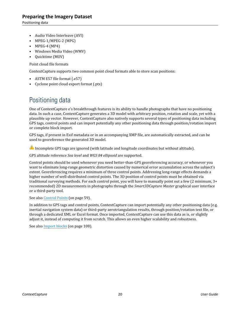
Positioning dataOne of ContextCapture e's breakthrough features is its ability to handle photographs that have no positioningdata. In such a case, ContextCapture generates a 3D model with arbitrary position, rotation and scale, yet with aplausible up vector. However, ContextCapture also natively supports several types of positioning data includingGPS tags, control points and can import potentially any other positioning data through position/rotation importor complete block import.GPS tags, if present in Exif metadata or in an accompanying XMP file, are automatically extracted, and can beused to georeference the generated 3D model.
Incomplete GPS tags are ignored (with latitude and longitude coordinates but without altitude).GPS altitude reference Sea level and WGS 84 ellipsoid are supported.Control points should be used whenever you need better-than-GPS georeferencing accuracy, or whenever youwant to eliminate long-range geometric distortion caused by numerical error accumulation across the subject'sextent. Georeferencing requires a minimum of three control points. Addressing long-range effects demands ahigher number of well-distributed control points. The 3D position of control points must be obtained viatraditional surveying methods. For each control point, you will have to manually point out a few (2 minimum, 3+recommended) 2D measurements in photographs through the Smart3DCapture Master graphical user interfaceor a third-party tool.See also Control Points (on page 59).In addition to GPS tags and control points, ContextCapture can import potentially any other positioning data (e.g.inertial navigation system data) or third-party aerotriangulation results, through position/rotation text file, orthrough a dedicated XML or Excel format. Once imported, ContextCapture can use this data as is, or slightlyadjust it, instead of computing it from scratch. This allows an even higher scalability and robustness.See also Import blocks (on page 108).
Preparing the Imagery DatasetPositioning data
ContextCapture 20 User Guide

3ContextCapture
PrincipleContextCapture takes as input a set of digital photographs of a static subject, taken from different viewpoints.Various additional input data may be provided: camera properties (focal length, sensor size, principal point, lensdistortion), positions of photos (GPS), rotations of photos (INS), control points, ...Without manual intervention and within a few minutes/hours of computation time depending on the size of theinput data, ContextCapture outputs a high resolution textured triangular mesh.The output 3D mesh constitutes an accurate visual and geometric approximation of the parts of the subjectadequately covered by input photographs.Suitable Subjects
ContextCapture 21 User Guide

ContextCapture 's versatility allows to seamlessly reconstruct subjects of various scales, ranging fromcentimeters to kilometers, photographed from the ground or from the air. There is no limit in the precision ofthe resulting 3D model, other than the resolution of the input photographs.ContextCapture performs best for geometrically-complex textured matte surfaces, including but not limited tobuildings, terrain and vegetation.Surfaces with no color variation (e.g. solid color walls/floors/ceilings), or with reflective, glossy, transparent orrefractive materials (e.g. glass, metal, plastic, water, and to a lesser extent, skin) may cause holes, bumps or noisein the generated 3D model.ContextCapture is intended for static subjects. Moving objects (people, vehicles, animals), when not dominant,can be handled at the price of occasional artifacts in the generated 3D model. Human and animal subjects shouldremain still during acquisition, or should be photographed with multiple synchronized cameras.
Capturing close range - mid range subjects
This is a common bottleneck in many sectors: architecture, engineering & construction; manufacturing; media &entertainment; e-commerce; scientific analysis; cultural heritage. ContextCapture dramatically enhancesproductivity and opens new business opportunities in these different sectors, as illustrated by the examplebelow.
Figure 6: Autun Cathedral: Tympanum (courtesy of On-Situ)
Mapping large-scale urban or natural environments
ContextCapture goes beyond the photo-realistic flyovers, generated from tightly-controlled aerial imagery,offered by some popular online map services. It allows, in a completely automated manner, to turn variousimage sources (aircraft, helicopter, UAV, street-level) into a consistent and accurate real-3D modelencompassing all scales, from large-scale relief to finer details of man-made constructions and objects andnatural landmarks.
ContextCapturePrinciple
ContextCapture 22 User Guide

Figure 7: Paris (courtesy of InterAtlas)
Figure 8: Street 3D model (courtesy of V3D)
ArchitectureThe two main ContextCapture modules are ContextCapture Master and ContextCapture Engine. They follow amaster-worker pattern:• ContextCapture Master (on page 30) is the master module of ContextCapture . Through a graphical user
interface, it allows you to define input data and processing settings, to submit processing tasks, to monitor
ContextCaptureArchitecture
ContextCapture 23 User Guide

the progress of these tasks, to visualize their results, etc. The Master does not perform the processing tasks.Instead, it decomposes tasks into elementary jobs which it submits to a job queue.
• ContextCapture Engine (on page 198) is the worker module of ContextCapture . It runs on a computer in thebackground, without user interaction. When it is not busy, the Engine takes a pending job in the queue,depending on its priority and date of submission, and executes it. A job usually consists of processingaerotriangulation or 3D reconstruction, using various computationally intensive algorithms (keypointextraction, automatic tie point matching, bundle adjustment, dense image matching, robust 3Dreconstruction, seamless texture mapping, texture atlas packing, level-of-detail generation, ...).
For automation needs, ContextCapture Master interface can also be replaced by calls to a Python API. See alsoContextCapture ContextCapture (on page 214).Thanks to this master-worker pattern, ContextCapture supports grid computing. You can dramatically reduceprocessing time simply by running multiple ContextCapture engines on several computers, and associate themto a same job queue.ContextCapture 's grid computing ability is based on the operating system's native file sharing mechanism. Thisallows ContextCapture to transparently handle a SAN, a NAS or a shared standard HDD. No specific gridcomputing architecture needs to be deployed.
• ContextCapture Viewer (on page 200) is ContextCapture 's free lightweight visualization module. It isoptimized for ContextCapture 's native format, which handles level-of-detail, paging and streaming, thusallowing visualization of terabytes of 3D data, locally or online, with a smooth frame rate. You can useContextCapture Viewer in conjunction with ContextCapture Master to control production quality all along theworkflow. You can also use it to navigate final results.
• ContextCapture Installation (on page 10): to manage configuration of ContextCapture .• License Management Tool: to manage licensing of ContextCapture .
ContextCaptureArchitecture
ContextCapture 24 User Guide

Workflow
Figure 9: ContextCapture workflow
From the ContextCapture Master user interface, one operator (in some cases, there may be several operatorsworking in parallel) define input data and processing settings, and submits the corresponding 3D reconstructiontask to the job queue. One or several ContextCapture engines, when available, process the different elementaryjobs, and store the results at the location defined by the operator in the ContextCapture Master user interface.From this interface, the operator can also directly monitor the status and progress of these jobs (Learn moreabout Job Monitoring (on page 215). After the jobs are completed, the output 3D model is ready.Retouching
In most cases, the automatically generated 3D model can be used as is. But for some specific applications, anoperator may prefer to fix the occasional geometric defects of the automatically generated 3D model in somethird-party software, input this retouched 3D geometry in the ContextCapture Master user interface, and submita novel 3D reconstruction task. In this case, the output 3D model is updated accordingly by automaticallymapping texture to the retouched 3D geometry.Learn more about Retouching (on page 187).
System RequirementsContextCapture natively runs under Microsoft Windows 8/10 64-bit.It requires at least 8 GB of RAM and NVIDIA or AMD graphics card, or Intel-integrated graphics processorcompatible with OpenGL 3.2 with at least 1 GB of dedicated memory.
ContextCaptureWorkflow
ContextCapture 25 User Guide

For specific Annotation jobs leveraging artificial intelligence, minimum GPU requirement are higher. A 4.0GBNVIDIA device with up-to-date drivers is the minimum we require.Both desktop and rack-mounted computers are supported. Even multimedia or gaming laptops can be used,though with a significantly lower performance.As of January 2020, the following configuration is recommended: a recent desktop computer running underMicrosoft Windows 8/10 64-bit with 64 GB of RAM, an 8+core i9-CPU and an NVIDIA GeForce RTX 2080 Tigraphics card. Please contact the technical support team to design more powerful configurations (GeForceTITAN RTX, SSD Drives, etcetera.).Input, working and output data should preferably be stored on fast storage devices (fast HDD, SSD, SAN). For filesharing, we recommend a >1-Gigabit Ethernet network.
About Remote desktop connection
ContextCapture Engine cannot work through a Remote Desktop Connection because hardware acceleration isdisabled. However, you can use VNC or a remote administration software like TeamViewer.
About Windows session
Switching Windows user while ContextCapture Engine is running will cause running computations to failbecause hardware acceleration is disabled when the user is not connected.
About paths with non-ASCII characters
ContextCapture does not support paths with non-ASCII characters. All specified input and output file pathsmust use only ASCII characters.
PerformanceContextCapture exploits the power of general purpose computation on graphics processing units (GPGPU),yielding 50-times faster processing for some operations (image interpolation, rasterization, z-buffering). It alsouses multi-core computing to speed up some CPU-intensive parts of the algorithms.ContextCapture can process 10 to 20 gigapixels per day and per ContextCapture Engine on average, dependingon the hardware configuration, for the production of a textured 3D mesh with Extra precision. For input pointcloud datasets, ContextCapture can process about 250 million of points per day and per ContextCapture Engine.You can dramatically reduce processing time with grid computing, simply by running multiple ContextCaptureengines on several computers, and associate them to a same job queue.Example: for vertical + 4-oblique aerial datasets with a ground resolution of 10-15 cm and a typical overlap, wehave observed an average production rate of 30-50 km² per day on a cluster of 4 ContextCapture Engines.Regarding memory use, one ContextCapture Engine with 8 GB of RAM can handle up to 1 gigapixel of input dataand 10 million output triangles in one job.
ContextCapturePerformance
ContextCapture 26 User Guide

Software EditionsContextCapture edition
ContextCapture automatically reconstructs objects, buildings, man-made or natural landmarks, from imagerydatasets of up to 300 gigapixels, or point clouds up to 3 billion points and a batch processing ability through ajob queue. Most suited for, but not limited to, UAS /UAV/drone operators, this edition allows the production ofhigh resolution 3D models as well as the generation of digital surface models (DSM) and true orthophoto.ContextCapture Center edition
ContextCapture Center is dedicated to larger-scale 3D surveying and mapping. It can handle an unlimitednumber of photographs without any limitation in size, and allows computations to be parallelized on a cluster of3D reconstruction engines. It can import complex positioning data (example, inertial navigation system data),third-party aerotriangulation results and surface constraints. Consequently, it is adapted to massive 3D contentproduction, like entire 3D cities from the air or from a mobile mapping system.It can be customized to customer needs, for a seamless integration into the most demanding 3D productionpipelines.Compare ContextCapture editions
Features ContextCapture ContextCapture Center
Input imagery datasets ≤ 300 gigapixels Unlimited
Input point cloud datasets ≤ 3 billion points Unlimited
Automatic aerial triangulation /calibration
Automatic true 3D reconstruction(3D TIN)
Georeferencing
True orthophoto / DSM generation(GeoTIFF, JPG...)
Dense point cloud generation (LAS,POD, LAZ)
CAD interoperability (OBJ, FBX,Collada, STL, DGN...)
ContextCaptureSoftware Editions
ContextCapture 27 User Guide

Features ContextCapture ContextCapture Center
3D GIS interoperability (Agency9CityPlanner, Eternix Blaze Terra,Google Earth, Skyline TerraBuilder,SpacEyes3D Builder, Supermap GIS,DIGINEXT VirtualGEO...)
Annotations (2D/3D objects,segmentation)
Free Viewer / web publishing
Unlimited tiling
Task queuing / backgroundprocessing
SDK / Python scripting
Grid computing ≤ 2 computers Unlimited
Reconstruction constraints (watersurfaces…)
Quality control
Warning: Project file compatibility between ContextCapture editions is restricted. Reading of project filescreated from a higher edition is not permitted.
InteroperabilityContextCapture is fully interoperable with 2D/3D GIS and CAD solutions through dedicated formats or vianeutral formats.ContextCapture can also export accurate camera properties, positions, orientations in various exchange formats.See also Export (on page 114) and Output formats (on page 161).
CAD/3D Software
With the standard Wavefront OBJ, Collada DAE, and FBX formats, 3D models generated by ContextCapture canbe exported to a vast majority of CAD and 3D solutions including Bentley MicroStation, Autodesk 3ds Max,Autodesk AutoCAD, Rhinoceros 3D, Autodesk Maya, Autodesk Mudbox, Autodesk MeshMixer, MeshLab.
ContextCaptureInteroperability
ContextCapture 28 User Guide

ContextCapture can generate 3D meshes with multiple level of detail (LOD) to ease integration of large datasetsinto 3D solutions supporting this optimization.For very large 3D models - such as cities - using the above formats can prove challenging, even with the LODsystem. In this case, the 3MX format can be used to export the model to Bentley MicroStation.
2D/3D GIS software
Georeferenced 3D models can be produced in any coordinate system ( ContextCapture includes more than 4000spatial reference systems and can be extended with user-defined ones) and in custom tiling systems compliantwith GIS applications.ContextCapture can produce 3D mesh models with level-of-detail and paging directly compatible with severalleading 3D GIS software: TerraExplorer (Skyline), SpacEyes3D Builder, CityPlanner (Agency9), VirtualGeo(DIGINEXT), Blaze Terra (Eternix), Supermap GIS, Google Earth, Cesium and more to come.ContextCapture can generate true - orthophotos and DSM compatible will all standard GIS tools.ContextCapture can export dense point clouds in ASPRS LASer (LAS) and Pointools POD format with colorinformation on each point, that can be used in most point cloud analysis and classification software.
3D VisualizationContextCapture includes ContextCapture Viewer, a free downloadable lightweight 3D visualization applicationworking locally or online, under Windows.3D visualization
ContextCapture Viewer is optimized for ContextCapture 's native 3MX, which handle level-of-detail, paging andstreaming, thus allowing visualization of terabytes of 3D data with a smooth frame rate.ContextCapture Viewer integrates 3D measurement tools (3D position in a configurable Spatial referencesystem, 3D distance and height difference, surface and volume computation) and tile selection tools.You can use ContextCapture Viewer in conjunction with ContextCapture Master to control production quality allalong the workflow. You can also use it to navigate final results and generate fly-through animations.Free and downloadable on http://www.bentley.com, ContextCapture Viewer offers an instant solution forpublishing 3D models in ContextCapture 3MX and S3C formats.
Web publishingContextCapture users have several options for publishing their original 3D content on the Internet.• Share images, scans, orientations and productions on ProjectWise ContextShare.• Publish 3MX production with ContextCapture Web Viewer 1.0.• Publish 3D Tiles to Cesium or to ContextCapture Web Viewer 2.0.• Share S3C productions online.• Publish to Sketchfab (OBJ format)Learn how to share and publish ContextCapture contents.
ContextCapture3D Visualization
ContextCapture 29 User Guide

4ContextCapture Master
The ContextCapture Master is the master module of ContextCapture . Through a graphical user interface, itallows you to:• Import the data sets,• Define the processing settings,• Submit tasks,• Monitor the progress of submitted tasks,• Visualize results, etc.The Master does not perform the processing tasks. Instead, it decomposes tasks into elementary jobs which itsubmits to a job queue.ContextCapture Master 's main interface manages the different steps of the ContextCapture workflow through aproject.A project is organized along a tree structure. It contains items of different types, corresponding to each step ofthe workflow:• Project (on page 31): A project manages all data relative to a scene processed by ContextCapture . It
contains one or several blocks as sub-items.• Block (on page 45): A block manages a set of input photos and their properties (photogroup properties:
sensor size, focal length, principal point, lens distortion / pose: position, rotation), based on which one orseveral reconstructions can be created. These reconstructions are represented as sub-items of the block inthe tree structure.
• Reconstruction (on page 134): A reconstruction manages a 3D reconstruction framework (spatial referencesystem, region-of-interest, tiling, retouching, processing settings), based on which one or several productionscan be launched. These productions are represented as sub-items of the reconstruction in the tree structure.
• Production (on page 158): A production manages the generation of a 3D model, with error feedback,progress monitoring and notifications about updates of the underlying reconstruction (e.g. retouching).
A project can contain multiple items corresponding to a same step of the workflow, which allows complexversioning and/or variant management. This is very useful to experiment on a same scene with different inputdata and different processing settings.The main interface is in the form of a project explorer from which you can browse all the items of a project.
ContextCapture 30 User Guide

Figure 10: ContextCapture Master main interface
You can navigate in the project from the project tree view:• The project tree view provides a direct access to any item in the project and provides an overview of the
project (it includes a preview of the status of each project item).The central area (project item view) manages data and actions relative to the active item. Its content depends onthe type of the active item (project, block, reconstruction or production).For some specific actions, the interface guides you through the workflow using dedicated modal dialogs orwizards.ContextCapture Master submits jobs to ContextCapture Engine through a job queue. The Job Queue Monitor (onpage 179) panel displays an overview of the job queue status and progress.
ProjectThe Project item manages all data relative to a scene processed by ContextCapture .
ContextCapture MasterProject
ContextCapture 31 User Guide

Figure 11: Project item interface
The project item is defined by a list of blocks and project options, managed from two tabs:• The General (on page 32) tab manages the list of project blocks.• The Options (on page 34) tab allows to set some options useful for computer clusters.For the project, the Reference manager (on page 35) allows to check resources, and to repair or update links.The Basemap manager (on page 38) is used to manage basemap layers accessible from project 3D views.Project file compatibility between ContextCapture editions is restricted. Reading of project files created from ahigher edition is not permitted. See Software Editions (on page 27).
General
The project General tab displays project dashboard and manages the list of project blocks.
ContextCapture MasterProject
ContextCapture 32 User Guide

Figure 12: The project General tab
DashboardThe General tab may display contextual information about the project status.
Figure 13: Example of project dashboard
BlocksThe project manages a list of Block (on page 45). You can create new blocks in different ways, or removeexisting ones.
Create a new block from photos.
Creating a new block starts the ContextCapture workflow from scratch.
Import blocks from XML or XLS file.
Imports complete or partial blocks definitions from a BlocksExchange XML file or from MS Excel file.See Import blocks (on page 108).
Divide block into several parts (available only for a georeferenced aerial block).
ContextCapture MasterProject
ContextCapture 33 User Guide

See Split block (on page 109).
Extract region from block (available only for a georeferenced aerial block).
See Extract block (on page 112).
Remove block from project.
Remove all the block content including reconstructions and productions.
Options
The project Options tab enables UNC paths definition and job queue management, helping cluster computing.
Figure 14: The project Options tab
UNC pathsWhen using ContextCapture on a cluster, Universal Naming Convention (UNC) paths are required for distantaccess to input, project, and output files.Warn when a non-UNC path is used (advised when using a computer cluster)
This option activates warnings in the user interface when a non-UNC path is used:• for the project file location,• for photo files,• for the job queue directory,• for the production output directory.Use proxy UNC path for the project file
Even if UNC paths are used everywhere in a project file, if the project is opened from a local location (forinstance double-click on the CCM file in the local directory), non-UNC paths may be introduced in jobs and causethe computer cluster to fail.To avoid this common cause of error, the proxy UNC path allows to define the UNC project file path used byContextCapture , independently of the location the project is opened from.
ContextCapture MasterProject
ContextCapture 34 User Guide

Job queueDefines the directory where jobs must be submitted for processing by ContextCapture Engine.This option allows to modify the job queue directory of a project. The job queue directory of a new project isinitialized to the default value set by ContextCapture Settings (see Installation (on page 10) and Configuration(on page 11)).
ProjectWise projectYour ContextCapture project can be associated to a ProjectWise project.
Figure 15: ProjectWise project chooser
Simply select a ProjectWise project to be associated with your work. See the ProjectWise Project Chooserdocumentation for more details on the various capabilities of this window. When associated, all use of theproject in the current product is associated with the ProjectWise project.
Reference manager
Check resources, repair or update links.ContextCapture projects refer to several external resources: input photos and masks, as well as outputdirectories. The reference manager interface allows you to check, repair or update corresponding links.Some resources may be synchronized with the cloud. The reference manager dialog allows to check and controlthe synchronization.
ContextCapture MasterProject
ContextCapture 35 User Guide

Figure 16: The reference manager interface
Note: If the project contains unloaded blocks, the reference manager will temporary load them in order tomanage project references properly (see also Load/unload blocks (on page 117)).Check resources status with Update status. Repair or update links with the Replace in paths tool, or editingresources paths directly.Changes appear in bold characters in the resources table and are actually applied only when you click on Applychanges.
FilterFilter resource table.
Use the filter to quickly find resources from their location.Filter supports simple wildcard matching (?, *, etc.)
Update StatusCheck access to resources and update the status column accordingly.
Replace in pathsMake changes in file paths.
ContextCapture MasterProject
ContextCapture 36 User Guide

Figure 17: Replace in path dialog Enter the text to replace in Find what and the new text in Replace with.
Enter the text to replace in Find what and the new text in Replace with.Look in: select All items to apply replacement to all the items of the current filter result, or Selected item to limitthe replacement to the corresponding selection.Find options: enable Match case or Use regular expression to perform advanced replacement operations.
Management at resource levelRight click on a resource to display the resource context menu.
Figure 18: Resource context menu
Apply changesApply pending changes (in bold).
Changes are applied only when you actually click on Apply changes.
ContextCapture MasterProject
ContextCapture 37 User Guide

Depending on project complexity, applying path changes may take a significant time.
Cancel changesCancel all changes which are not applied yet (in bold), and restore initial values.
Basemap manager
The basemap manager is used to manage basemap layers accessible from project 3D views.A basemap is a 3D representation of geospatial data used in project 3D views as context or as reference data. It ismade of a Digital Terrain Model and a georeferenced image.Your project must be georeferenced to be able to add basemaps.ContextCapture can create basemaps from terrain and image data downloaded directly from Bentley’sGeoCoordination Services or from local terrain and image files.About Bentley GeoCoordination Services
GeoCoordination Services is a geospatial data indexation service that allows you to easily find and downloadavailable data on your project area. It allows you to request the list of available data on the area, and get aselection of data for your project.GeoCoordination Services proposes data on the following countries: USA, Canada. More countries will becovered in future versions.GeoCoordination Services if a service reserved to Bentley CONNECT users. You must be logged in with BentleyCONNECT Edition to use it.Notes: The GeoCoordination Services URL can be changed from ContextCapture Options. By default the followingURL is used: “https://connect-contextservices.bentley.com/v2.3/Repositories/IndexECPlugin--Server/”.To open the basemap manager:• from the project menu: select Basemap manager• from the block 3D view, or from the reconstruction 3D view: click on the Layers button and select• Basemap manager in the layers menu.
ContextCapture MasterProject
ContextCapture 38 User Guide

Opening the basemap manager from the block 3D view layers menu.
ContextCapture MasterProject
ContextCapture 39 User Guide

The basemap manager windowTo add a new basemap, click on Add in the Basemap manager window, or directly select Add basemap from thelayers menu in the 3D views.Name
Basemap aliasEnter your preferred name for the basemap to be added.
ContextCapture MasterProject
ContextCapture 40 User Guide

Adding basemap: the name pageThe name can also be changed later from the basemap manager dialog.Region of interest
Select the bounding rectangle of the basemap to create. The region of interest is used to request data fromGeoCoordination Services, and to crop the selected input data to the area of interest.
ContextCapture MasterProject
ContextCapture 41 User Guide

Adding basemap: the region of interest pageFor blocks with existing photo positions, the initial region of interest is automatically set to contain all thepositions with a margin. To change it you can edit bounds in the coordinate system you want, or import a KMLpolygon.Data selection
Select the list of data used to build the basemap.The list of data contains spatial layers found by GeoCoordination Services on the given region of interest,
ContextCapture MasterProject
ContextCapture 42 User Guide

Adding basemap: the data selection pageClick on More details to get on overview of the selected data.
ContextCapture MasterProject
ContextCapture 43 User Guide

Selected dataset detailsYou can also add local terrain or image files.Supported local files are:For terrain: raster DTM with known registered coordinate system in the following file format: GeoTiff, IMG. ASC.For imagery: Image file with known registered coordinate system in the following file format: GeoTiff, JPEG2000,JPG, ECW.Options:Discard data outside the region of interest (default: activated): if disabled all the selected input data will be kept.Height reference for input terrain file (default: Mean Sea Level): select the height reference for input terrain files.Most terrain files are based on Mean Sea Level, however we recommend to use terrain file based on the WGS84ellipsoid to avoid precision loss when importing heights.Select the list of layers to use to create the basemap, and click on Download and import to proceed.ContextCapture starts by downloading data from remote servers if required, then process the 3D terrain modelcache for rendering. Operation time will depend on the quantity and size of the data.
ContextCapture MasterProject
ContextCapture 44 User Guide

Example of a basemap created from GeoCoordination Services data
Free Up Disk Space
This tool allows to cleanup project temporary files to save disk space.
BlockA Block item manages a set of input data used for 3D reconstruction: photos and/or point clouds. The block itemmanages photos and their properties (photogroup properties: sensor size, focal length, principal point, lensdistortion / pose: position, rotation), and optional point clouds.Based on the block item, one or several reconstructions can be created.A photo can be used for 3D reconstruction if it is complete. A photo is complete if it fulfills the followingconditions:• Its image file is in a supported file format (see Input data file formats (on page 19)) and is not corrupted,• Its photogroup properties and pose (see Useful concepts (on page 15)):
• Are known accurately,• Are consistent with the ones of other photos.
ContextCapture MasterBlock
ContextCapture 45 User Guide

To achieve the two above conditions, photogroup properties and photo poses must result from a jointoptimization of the different photos of the block. The set of consistently optimized photos constitutes the maincomponent of the block.You can obtain a set of complete photos by two main methods:• By adding photos to the block, with only a coarse guess of photogroup properties, and then by using
ContextCapture 's aerotriangulation to estimate complete and accurate photogroup properties and photoposes.
• By importing photos with complete and accurate photogroup properties and photo poses (e.g., from third-party aerotriangulation software) from an XML file (see Import blocks (on page 108)).
Figure 19: Block item interface
The block item is defined by the following properties:• Photos (on page 48): the photos you imported or added, and their associated photogroup properties and
photo poses (computed by Aerotriangulation (on page 87), or imported).• Point clouds (on page 54): imported from point cloud files.• Control Points (on page 59): Control points or user tie points entered manually, or imported. Survey points
are optional.• Tie points (on page 64): automatically extracted by ContextCapture , or imported.• Surveys: Positioning Constraints (on page 66): position/orientation/scale priors based on user tie points.• Additional data (on page 86) additional knowledge on the acquisition used to help aerotriangulation.• List of reconstructions based on the block.The block General (on page 47) tab manages the block dashboard and block reconstructions.
ContextCapture MasterBlock
ContextCapture 46 User Guide

For convenience, a block with some known 3D data (photo poses, control points, point clouds) can be displayedin 3D in the Block 3D view (on page 72) tab.For a block, the following features are proposed:• Import blocks (on page 108): import blocks from XML file.• Export (on page 114): block can be exported to various file formats.• Split block (on page 109): divide a large aerial block into several parts.• Extract block (on page 112): extract region from block.• Load/unload blocks (on page 117): load/unload blocks from the active project.• Merge blocks (on page 118): merge a selection of blocks into one new block.• Share on ProjectWise ContextShare (on page 117): share images and orientations on Share on ProjectWise
ContextShare (on page 117).Note: Once a reconstruction is created, properties are read-only. You can clone the block to get a new editableblock initialized with the same properties.
General
The block General tab manages the block dashboard and the list of reconstructions of the block.
Figure 20: Block General tab
DashboardThe block General tab gives an overview of the block and possible actions in the workflow.At any time, clicking on Submit Aerotriangulation (on page 87) will start processing a new block with completeor adjusted photogroup properties and/or photo poses processed locally with ContextCapture Engine or on thecloud (see Process on the cloud).While the aerotriangulation of a new block is in progress, the block General tab is instead dedicated tomonitoring.
ContextCapture MasterBlock
ContextCapture 47 User Guide

ReconstructionsManages the list of reconstructions of the block.
Create a new reconstruction framework.
Remove the selected reconstruction from block.
See also Reconstruction (on page 134).
Photos
The Photos tab is used to manage the set of photos and the associated properties.Note: Once the block contains one or several reconstructions, the Photos tab is read-only.
Figure 21: Block photos tab
Adding PhotosFor optimal performance, photographs must be divided into one or more photogroups. Photogroups arehomogeneous sets of photographs, all taken with the same physical camera with identical interior orientation(image dimensions, sensor size, focal length,...). If the photos are organized in subdirectories according to thecamera used to shoot them, ContextCapture can automatically determine relevant photogroups.
ContextCapture MasterBlock
ContextCapture 48 User Guide

See also Input data file formats (on page 19).The size of the imagery dataset may be limited according to your edition. See Software Editions (on page 27).
Add a selection of photo files.
Use Shift or Ctrl to perform a multi-selection.
Add all photos of a given directory (recursively or not).
This command browses the chosen directory and adds all the photos found in this directory that are in asupported format.
Download and add photos from image collections on ProjectWise ContextShare.
This command allows to select image collections from the cloud, download them, and add them to the block.See also Input data file formats (on page 19).
Extract frames from a video file and add them to the block.
See Import video frames (on page 100).
Remove photos or photogroups selected in the table.
Use Shift or Ctrl to perform a multi-selection.
PhotogroupsPhotogroup properties
Photogroup properties define the interior orientation of the camera. Accurate estimates of photogroupproperties are required for 3D reconstruction. These estimates can either:• Be automatically estimated by ContextCapture by aerotriangulation, starting from some coarse estimates
derived from EXIF metadata or using the ContextCapture camera database.• Be imported (when importing a block, or from the camera database, or from an OPT file).• Or entered manually.Multi-camera rig
Specifies if the photogroup defines a camera device that is part of a multi-camera rig. The supported options areNone or Main. For a multi-camera rig setup to be valid, all the photogroups of the block must belong to it and allof them must fulfill the requirements of such setup.Camera model type
Two camera model types are supported:
ContextCapture MasterBlock
ContextCapture 49 User Guide

• Perspective: perspective projection combined with a classical Brown's distortion model, suited for rectilinearlens or lens with low distortion.
• Fisheye: Suited for wide-angle or fish-eye lens with extreme lens distortion.For more information about ContextCapture camera models, see doc/ContextCapture camera model.pdf.Camera model band
Two camera model band are supported:• Visible: standard RGB camera capturing visible colors.• Thermal: Far Infra Red camera capturing temperature.Sensor size
ContextCapture may need to know the size of your camera's sensor. The needed sensor size is the sensor'slargest dimension. If your camera model is not already listed in our database, you will be asked to enter thisinformation. If you are unsure of your camera's specifications, you can consult the Digital Photography Reviewor contact Bentley Systems technical support.Note: When a camera model is not listed in our database, the interface proposes to send a request to BentleySystems. We will reply to your email in a timely manner, and we will include the missing camera model in thedatabase of the next ContextCapture release.
Note: An undefined sensor size may be acceptable in some specific cases, e.g. if the 35mm-equivalent focal lengthis known from EXIF metadata.Focal length
For a newly created photogroup, ContextCapture can generally extract a coarse guess of the focal length in mmfrom EXIF metadata. Otherwise, you will be asked to enter this initial guess. Later, ContextCapture canautomatically estimate the focal length more accurately by aerotriangulation.We recommend to specify sensor size and/or focal length for each photogroup. If these properties are missing,ContextCapture will assume that the 35 mm equivalent focal length equals to 50 mm. If the correct focal lengthvalue differs significantly, the aerotriangulation may fail. In such cases it is required to specify initial cameraproperties manually.For fisheye camera models, the focal length is ignored as soon as a fisheye focal matrix is defined (see below).Fisheye focal matrix
For the camera model type Fisheye, the fisheye focal matrix overrides the focal length property to modelasymmetric fisheye focals.Not used for perspective camera models.Principal point
For a newly created photogroup, ContextCapture considers that the principal point is by default at the center ofthe image. Later, ContextCapture can automatically estimate the principal point more accurately byaerotriangulation.Distortion
For a newly created photogroup, ContextCapture considers that there is by default no lens distortion. Later,ContextCapture can automatically estimate lens distortion more accurately by aerotriangulation.Not used for fisheye camera models.
ContextCapture MasterBlock
ContextCapture 50 User Guide

Fisheye distortion
Distortion model for the fisheye camera models.Not used for perspective camera models.Aspect ratio/Skew
Properties used when pixels are not square.• Skew: coefficient defining the angle between x and y pixel axes.• Aspect ratio: different from 1 if the pixel are not square.Manipulating a photogroup
Get from the camera database/add to the camera database
The camera model of photogroup can be added to or obtained from the camera database.
Figure 22: Accessing the camera database from a photogroup
See also Camera database (on page 129).Export/import optical properties
The properties of a photogroup (including sensor size, focal length, distortion, and principal point) can beexported and re-imported to/from an OPT file.This feature can be used to re-use a camera calibration.To import or export the optical properties, right click on a photogroup and choose Export optical properties orImport optical properties from the context menu.Ungroup/group photogroups
In some specific cases, the interior orientation of the camera must be estimated independently for each photo:for example, if photos were taken by a camera rig, or if the focal length varied slightly from one photo to theother during acquisition (zoom lens).In such case, we recommend to prepare the dataset before adding photos in ContextCapture by placing eachphoto in a different subdirectory, to conform to Photo acquisition (on page 17). However, it is also possible to
ContextCapture MasterBlock
ContextCapture 51 User Guide

add photos as is and use the Ungroup function: select all photogroups in the table, right click and chooseUngroup from the context menu to get one photogroup per photo.See also Photo acquisition (on page 17).
Photo propertiesImage
Each photo references an image file.To edit references use the Reference manager (on page 35).Pose (position/rotation)
Photo position and rotation define the estimates of the photograph pose. Accurate estimates of photo poses arerequired for 3D reconstruction. These estimates can either:• Be automatically computed from scratch or adjusted by ContextCapture by aerotriangulation,• Be initialized from pose metadata (see below),• Or entered manually.Pose metadata (position/rotation)
Metadata position and rotation define the known pose of the photograph. This metadata can be imported fromGPS tags, third-party data, or during block import.Component
Another property of a photo is its component. Only the photos belonging to the main component of the block, i.e.photos resulting from a joint optimization, e.g. by aerotriangulation in ContextCapture or in third-party software,can be used for 3D reconstruction.Mask
A mask can be associated to a photo to cause specific parts of the image to be ignored in the workflow. A validmask is a black and white TIFF image with the same dimensions as the photo. Pixels of the photo correspondingto black pixels of the mask will be ignored during aerotriangulation and reconstruction.Masks are associated to input photographs through their file name:• Associate a mask to one photo: for a photo named "fileName.ext", the mask file must be named
"fileName_mask.tif" and placed in the same directory as the corresponding photo.Example: for a photograph "IMG0002564.jpg", the corresponding mask should be "IMG0002564_mask.tif"• Associate a mask to an entire directory (requires photos of same dimensions): if present in a directory, the
file "mask.tif" is used as a mask for all photos contained in this directory.Masks can also be assigned to photos from the user interface once photos are loaded: right click on a selection ofphotos to set or to clear the attached mask.See also Photo acquisition (on page 17).Manipulating photos
Use image GPS tags
GPS tags, if present in Exif metadata, are automatically extracted, and can be used to georeference the generated3D model.
ContextCapture MasterBlock
ContextCapture 52 User Guide

Incomplete GPS tags are ignored (with latitude and longitude coordinates but without altitude).After adding photos with complete GPS tags, you are notified that GPS altitude has been interpreted using sealevel as reference. Click on Modify to change the GPS altitude reference for the last added photos (Sea level orWGS 84 ellipsoid).See also Positioning data (on page 20).Import image positions and rotations from a text file
Import photo positions and rotations from a text file
Use this option to set image positions and rotations from 3rd party data stored in text format. This import is analternative to importing the entire block in XML or Excel format.The Import positions button is enabled only if the block is not empty, since the aim of this tool is to pair eachblock photo with a line in the text file that indicates that photo's position.For more details, please refer to the dedicated chapter Import photo positions (on page 102).Set the displayed Spatial reference system
For georeferenced blocks, use this option to change the spatial reference system used to display positioncoordinates. This is a display option which does not affect block properties.See also Spatial reference system (on page 192).Downsample photos
Define a downsampling rate
Downsampling photos reduces the quantity of information to process and affects the quality of results. It may beused to quickly produce a draft 3D model or to allow to process a large imagery dataset on a computer with alow hardware configuration and/or with a limited software edition.Applying photo downsampling does not modify input photos.Downsampling is defined by entering the percentage of original.
Photo downsampling affects the quality of results.Check image files
Check the integrity of image files
This tool tests all block photos in order to identify missing or corrupted image files.Two checking mode are proposed: Check image file header only (faster) , and Load the entire image file (slower).
For convenience, if invalid image files are found, you are proposed to remove them from the block.Preview an image
Select a photo and click on View to visualize the photo with the integrated Image viewer.
ContextCapture MasterBlock
ContextCapture 53 User Guide

Figure 23: Image viewer
About image quality
Depending on image size, the image viewer may use a compressed cached copy of the image. Press the 'O' key toload the original image.About image preview
ContextCapture Master generates photo thumbnails in the background to accelerate preview display.For very large images or when images are accessed from a remote location, preview creation may slow down theinterface. In such case, it is advised to disable the preview.
Point clouds
The Point clouds tab allows you to edit or display the set of input point clouds attached to a block.Note: Once a reconstruction is created in a block, the Point clouds tab is read-only.Importing point clouds
Limitation: ContextCapture only supports point clouds with known scan source positions. Moreover, if scansource positions specified in the imported point cloud are incorrect, it will adversely affect the 3D reconstructionor even cause a completely incorrect 3D reconstruction.
ContextCapture MasterBlock
ContextCapture 54 User Guide

The size of the imagery dataset and of the point cloud dataset may be limited according to your edition. See Software Editions (on page 27).Static scans
Point clouds can be imported from static scans in the following file formats:• ASTM E57 file format (.e57).• Cyclone point cloud export format (.ptx).• LAS/LAZ file format (.las, .laz).• POD Bentley point cloud format (.pod).When importing a georeferenced point cloud file, please specify the spatial reference system when importing thefile. Multiple files can be imported at once.The scanner position must be known to allow 3D reconstruction with ContextCapture. When it's not accessiblein the input file, the scanner position can be specified manually or detected automatically by ContextCapture bychecking the corresponding options. Be careful in this case that the input file corresponds to one scan acquiredfrom one unique position. To be able to automatically detect the scanner position, the scan must contain onlyscanner position that is clearly defined by an ellipse of high-density points on the ground. If you are importingmultiple files at once, the autodetect feature is still available and will detect one position per file.See also Pointclouds Technical Specifications (on page 270).Mobile scans
Point clouds can be imported from mobile scans in the following file formats:• ASTM E57 file format (.e57) with trajectory files.• LAS/LAZ file format (.las, .laz) with trajectory files.• NavVis PLY format (.ply).According to the format, the trajectories must be provided as separated text files (.txt or .csv) describingsuccessive scanner positions associated with time. ContextCapture integrates a text file import wizard to extracttrajectory data for various text formats.3D points of the provided point clouds must also include time data to be attached properly to the trajectories.See also Pointclouds Technical Specifications (on page 270).
ContextCapture MasterBlock
ContextCapture 55 User Guide

Figure 24: Import point cloud from mobile scans
Input files
Define the input point clouds and trajectory files.Trajectories and point clouds are linked through the time stamp in both sets of files.File format
Define how the trajectory files must be read.You can adjust the import parameters, so that each column in the Data preview table contains meaningfulinformation:• Number of lines to ignore at the beginning of the file: defines the length of the file header, and ignores it
during import.• Delimiters: defines the column separators. Several characters can be specified.
The option Combine consecutive delimiters can be required, for instance when sequences of white spaces areused as delimiter.
• Decimal separator: dot (123.456) or comma (123,456).Data properties
When importing a georeferenced point cloud file from mobile scans, please specify the suited spatial referencesystem. Note that the point clouds and the trajectories must be in the same spatial reference system.Fields
Specify role of columns for the trajectory data.You must associate each input column with its respective role.X (easting), Y (northing), Z (height/altitude) and time are required.
ContextCapture MasterBlock
ContextCapture 56 User Guide

Figure 25: Example of point clouds imported from aerial lidar scans
Import Scan Collections from ProjectWiseContextShare
Download and add point clouds from scan collections on ProjectWiseContextShare.This command allows to select scan collections from the cloud, download them, and add them to the block.Managing point clouds
Point clouds are made of a set of scans corresponding to various scan sources with distinct positions ortrajectories.
Figure 26: Point Clouds tab
Imported point clouds and scan positions are displayable in the block's 3D view tab.
ContextCapture MasterBlock
ContextCapture 57 User Guide

Figure 27: 3D display with scan sources of an imported point cloud file
Color mode
With this property you can select the color source for point cloud 3D display and texturing of the reconstructed3D model according to the available attributes in the imported point cloud:• Use color: use RGB color values.• Use intensity: use intensity value and map it to gray scale.• None: do not use point color.
Surveys
The Surveys tab allows you to edit or display the survey data attached to a block: Survey points and positioningconstraints.Note: Once a reconstruction is created in a block, the Surveys tab is read-only.
ContextCapture MasterBlock
ContextCapture 58 User Guide

Figure 28: The Survey tab
Survey points are optional positioning data used during the aerotriangulation of the block.Two types of survey points can be added:• Control points - allow to enter known 3D coordinates of one point located on photos and are used to register
the 3D scene.• Tie points - allow to identify one point on photos and are used to create positioning/scaling constraint, or to
stitch photos.Survey points can also be used after the aerotriangulation to identify positions on photos and to perform Qualitycontrol (on page 141).Positioning constraints are position/orientation/scale priors based on user tie points. They are used duringthe aerotriangulation of the block.Surveys data can be optionally extracted from photos in an automatic way using targets. (See Aerotriangulation).
Control PointsThe Surveys tab allows you to edit or display the survey data attached to a block: Survey points and positioningconstraints.Control points are registered in 2D-images and correspond to a same physical point with known 3D-coordinate.Note: Once a reconstruction is created in a block, the Control points tab is read-only.Control points can be added manually or can be imported from a columned file. See also Importing controlpoints (on page 61).UsageAdding control points to a block enables accurate geo-referencing and avoids long-range metric distortion.
ContextCapture MasterBlock
ContextCapture 59 User Guide

A set of control points can be used by aerotriangulation if it consists of 3 or more control points, each of themwith 2 or more image measurements.See also Aerotriangulation.Adding a control point1. Click on Add Survey Point.
2. Define Name.
In the Survey Point dialog, select Type “Control Point”.3. Enter 3D Coordinates
Select the input coordinate system in the combo-box, and the known 3D coordinates."Local coordinate system" system can be used to enter non-georeferenced control points with arbitrary unitsor with known units.
4. Click on CreateThe new Control point appears in the list.
5. You can set additional control point options (category, accuracy, check point, etc.) from the item properties(page 62).
6. Place the survey point on photos.Select a photo displaying the survey point, define its position in the photo with the yellow marker and clickAccept position (alternatively, use Shift+Click to set directly the position on the photo).
ContextCapture MasterBlock
ContextCapture 60 User Guide

Figure 29: Defining positions on photos
Repeat the sequence of operations above to set the position in several photos.
Importing control pointsThere are two ways to import control points:• With the block import: control points can be part of the block definition. See also Import blocks (on page
108)• With a control points text file imported from the Surveys tab (Import button).
Supported formats are TXT/CSV and ContextCapture Surveys (XML).A basic example of supported control points files is a simple TXT file listing control points 3D positions with XYZcoordinates separated by a space.Control points text file sample:GCP_A 315796.627695945 4869916.09237971 627.8GCP_B 315332.029686681 4870703.80261219 738.9GCP_C 315483.66078491 4870210.48269584 833.2GCP_D 315399.200463097 4871212.13895964 906.5
Thanks to the import wizard, you can import a custom text format with delimiter-separated-values, includingadvanced property like accuracy.When importing control points, please ensure you have selected the right spatial reference system (SRS) (See Spatial reference system (on page 192)).
ContextCapture MasterBlock
ContextCapture 61 User Guide
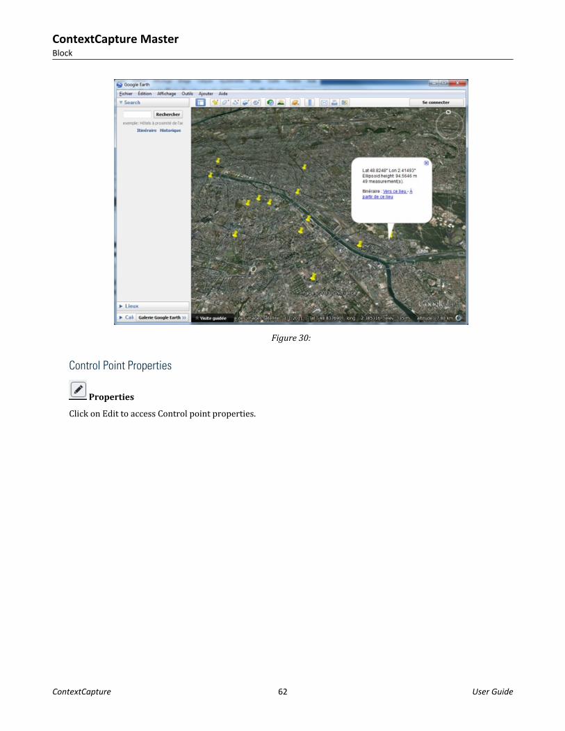
Figure 30:
Control Point Properties
Properties
Click on Edit to access Control point properties.
ContextCapture MasterBlock
ContextCapture 62 User Guide

Figure 31: Control point properties
NameControl point alias.
CoordinateWarning: for georeferenced control points, you must specify ellipsoidal height, and not the height above sealevel, if your spatial reference system does not specifically include an orthometric vertical datum. For the WGS84 reference system, for example, you must enter ellipsoidal heights; if your system is WGS 84 + NAVD 88 geoidheight, then you must use heights above sea level.For more information, please refer to Useful concepts (on page 15).Edit the control point 3D position in the corresponding fields. Coordinate units depend on the chosen coordinatesystem:• Local coordinate system: same unit for X, Y and Z (known unit or arbitrary unit).• WGS 84: latitude and longitude in degrees, ellipsoidal height in meters.• Other: X, Y and height in meters (according to the selected coordinate system).
Check pointEnable this option if you want to use the control point for checking only. In such case the control point will notbe considered during the aerotriangulation.
ContextCapture MasterBlock
ContextCapture 63 User Guide

Category
• Full: XYZ coordinates will be used (default).• Horizontal: only X and Y coordinates will be used.• Vertical: only Z coordinates will be used.
Horizontal accuracyEnter the given accuracy for the X and Y coordinates of the control point.Control points with a higher accuracy will have more weight in the aerotriangulation.
Vertical accuracyEnter the given accuracy for the Z coordinates of the control point.Control points with a higher accuracy will have more weight in the aerotriangulation.
Tie points
Note: Once a reconstruction is created in a block, the Tie points tab is read-only.Tie points are 2D correspondences corresponding to a same physical point with unknown coordinate.The survey tab manages only user tie point ie. tie point defined manually by the user. Note than ContextCapturecan automatically generate a large number of automatic tie points during the aerotriangulation process. SeeAutomatic Tie points.Tie points can be added manually or can be imported. See also Importing tie points (on page 66).
Usage
Used during the aerotriangulation of a block, user tie points can improve aerotriangulation accuracy and helpthe aerotriangulation in case of large baseline and ambiguous pattern. In most cases, user tie points are notrequired, because ContextCapture can cope with using only automatically generated tie points. User tie pointsshould be used only to solve aerotriangulation issues. In all cases, before acquiring user tie points, werecommend to run a first aerotriangulation.
Improve photo positionSome repetitive elements in photos can cause a photo to not be properly positioned.By defining points that represent the same position in different photos, you can guide the aerotriangulationprocess towards to correct photo positioning.
Group aerotriangulation componentsSometimes the aerotriangulation cannot connect all the photos due to a too large baseline or scale differencebetween some images.With user tie points defined across the picture set, the multi-pass aerotriangulation mode is able to stitch thepictures together. To enable aerotriangulation multi-pass mode, from aerotriangulation settings, set"Component construction mode" to "Multi-pass".
ContextCapture MasterBlock
ContextCapture 64 User Guide

At least 3 user tie points must be defined in 4 images (2 measures in each component that you want to fuse). Adding user tie points increases components connection chances, but the connection is never guaranteed.
Add positioning constraintsPositioning constraints are priors based on user tie points to provide scene origin/scale/orientation. Positioningconstraints are used to perform a rigid registration of the block during aerotriangulation.See also Geometry constraints (on page 141).
Label positionsYou can create user tie points to extract 3D-coordinates of points of interest. Once the scene is calibrated (afterAerotriangulation), ContextCapture can estimate accurately the 3D coordinates from 2D-pointing and can exportthis information (See Survey export).
Adding user tie points
1. Click on Add Survey Point.
2. Define Name.Note: We recommend to use an explicit name for each tie point to ease the identification of an individual usertie point (for the constraint definition, etcetera).
3. Select Type Tie Point.4. Click on Create.
The new Tie point appears in the list.5. Place the tie point on photos.
Select measurement photo displaying the point, define its position in the photo with the yellow marker andclick Accept position (alternatively, use Shift+Click to set directly the position on the photo).
ContextCapture MasterBlock
ContextCapture 65 User Guide

Repeat the sequence of operations above to set the position on several photos.
Importing tie points
There are two ways to import tie points:• With a ContextCapture Surveys file (XML) imported from the survey tab (Import button).• With the block import: user tie points can be part of the block definition. See also Import blocks (on page
108).
Surveys: Positioning ConstraintsPositioning constraints are position/orientation/scale priors based on user tie points. They are used to performa rigid registration of the block during aerotriangulation.
Positioning constraints are used only when using "Use positioning constraints on user tie points" mode duringaerotriangulation.You can set the origin and/or the scale and/or the orientation (either on axis or a plane).
ContextCapture MasterBlock
ContextCapture 66 User Guide

Figure 32: Example of a list of positioning constraints
Origin constraint
Add constraint type > Origin constraint
You cannot add an origin constraint if another origin constraint exists. Select the point corresponding to theOrigin O=(0,0,0).
Scale constraint
Add constraint type > Scale constraint
Select two points A and B and specify the distance between them.Select the distance unit if you know it, or use "units (arbitrary)" if it is not defined.You can add several scale constraints.
Axis constraint
Add constraint type > Axis constraint Orientation
constraint based on an axis.Select two points A and B and an axis, line AB being this axis (increasing values from A to B).
ContextCapture MasterBlock
ContextCapture 67 User Guide

You cannot add an axis constraint if another orientation constraint exists (axis or plane constraint).
Plane constraint
Add constraint type > Plane constraint Orientation
Constraint based on a plane
Select three points and two axes to specify a plane. You cannot add a plane constraint if another orientation constraint exists (axis or plane constraint).
Export Surveys
Click on the Export button to export Surveys in various file formats.
Figure 33: Export Surveys dialog
KML file
Georeferenced control points or tie points (if ContextCapture can estimate the 3D position) can be exported to aKML file; you then can use this file to visualize the points in a standard GIS tool or in Google Earth.
ContextCapture MasterBlock
ContextCapture 68 User Guide

Figure 34: Control points KML export displayed in Google Earth
Text file
Control points or tie points (if ContextCapture can estimate the 3D position) can be exported to a simple text filewith Name and coordinate (X, Y and Z).Survey points text file sample:GCP_A 315796.627695945 4869916.09237971 627.8
GCP_B 315332.029686681 4870703.80261219 738.9
ContextCapture Surveys file (XML)
All surveys data (including survey point properties, position on photos and positioning constraints) can beexported to XML format.
ToolsContextCapture provides various tools to ease the survey points acquisition: filters or sorts, display hints,etcetera.Photos filter
Use these options to apply filters on the list of photos.Status filters
ContextCapture MasterBlock
ContextCapture 69 User Guide

This filter allows to select photos according to their status for the selected Survey point.
All
Display all photosDisables filtering according to status for the selected survey point.Potential Matches
Display only recommended photos, on which the selected survey point may be placed.It uses the available positioning data of the block to find the photos.Note: In some cases, it may be interesting to process a first aerotriangulation with an approximategeoreferencing based on GPS tags or on few control points to be able to take advantage of the selection modebased on block orientation, and then acquire the entire control point set more easily.
Note: Potential Matches filter works for photos with known photogroup properties and pose.Incomplete block photos are not handled when using this selection mode.
ContextCapture takes advantage of the available block data, including the current survey data to improvepotential matches estimation: on a calibrated scene, potential matches become more relevant after adding thefirst survey points (typically from the 4th).In UseDisplay only photos where a position is already registered for the selected survey point.Sort
Two sorting modes are available:• Alphabetical: photos are sorted by name, alphabetically.• Distance from point: for a control point, closest photos are displayed first (ignoring rotation).Filter by nameAllow to select photos by name.
Image display optionsThese options allow to control the content of the image view.
Show/hide all potential positionsShow the potential position of all survey points on the current photo.For the selected survey point, the potential position is displayed with the placement marker (in yellow).For other surveys points, the potential positions are displayed with orange markers.
ContextCapture MasterBlock
ContextCapture 70 User Guide

Show/hide potential position of the current pointEnable epipolar lines display to highlight the potential matching region, or to check the survey point quality.Note: We recommend to process a first aerotriangulation, to be able to take advantage of the selection modebased on block orientation. This will greatly ease the process of defining user tie points.
Note: The display photo filter based on block orientation works for photos with known photogroup propertiesand pose.
Quality controlAfter aerotriangulation you can use the control point editor in order to control the positioning quality or toidentify errors.You can get statistics for each point, for each measurement or for each photo, or global statistics.You can get global statistics from the Survey Report.
Survey point itemsYou can get statistics for each survey point item, and for each measurement item: item border is coloredaccording to the reprojection error (see Reprojection error).Additional statistics are available from the item tooltip.
Quality metrics on a survey point item (colored border and tooltip)
Survey reportClick Report to display the Survey report.
ContextCapture MasterBlock
ContextCapture 71 User Guide

Quality metricsReprojection error
Reprojection error in pixels.All items are colored according to this value (or to the RMS of this value), with the following rules:
3D error
Distance in meters (or units) between the given 3D position and the estimated 3D position.Horizontal error
Horizontal distance in meters (or units) between the given 3D position and the estimated 3D position.Vertical error
Vertical distance in meters (or units) between the given 3D position and the estimated 3D position.
Block 3D view
The 3D view tab allows the user to visualize and control block's 3D data.
ContextCapture MasterBlock
ContextCapture 72 User Guide

Figure 35: Block 3D view
After aerotriangulation, the 3D model is enriched with generated tie points and splats. See also Splats.Use the mouse buttons to navigate the 3D scene.Double-click to focus the navigation on any point of the 3D scene. Click on the photos to display details.
Contents
Block 3D view content depend on the available data of the block. Content display can be controlled from theDisplay Styles drawer.
PhotosOnly photos with known position are displayed in the 3D view.Photos with complete pose (known position and rotation) are displayed with their oriented view frustum,selecting them allows to display their approximated field of view in 3D.
Photos are colored according to their calibration status and to the RMS of reprojection of their tie points.Color Reprojection error (px) Calibration status
< 1px Calibrated
ContextCapture MasterBlock
ContextCapture 73 User Guide

[1 px, 3px[ Calibrated
> 3 px Calibrated
Unknown Not calibrated (in a non-calibratedblock)
Unknown Not calibrated (in a calibratedblock)
Unknown Calibrated*
(*) May occur for imported photos without tie points
Survey pointsSurvey points symbols allows to identify the survey point type (user tie points or survey points, check point):Color Reprojection error (px)
Control point (used for calibration)
Control point "Check point" (not used for calibration)
User tie point (used for calibration)
User tie point "Check point" (not used for calibration)
Control points are located in the 3D view according to their actual 3D position; user tie points are located ontheir estimated 3D position.Survey points are colored according to the RMS of reprojection error of their measurements in input photos:Color Reprojection error (px)
< 1px
[1 px, 3px[
> 3 px
Unknown error
ContextCapture MasterBlock
ContextCapture 74 User Guide

Invalid survey point*
(*) Not enough measurementsYou can control camera size from the Display Styles drawer.Generated Tie points
Colored tie points generated by aerotriangulation.You can control point size from the Display Styles drawer.
SplatsSplats are an alternative representation of the tiepoints that adds textured surfaces to each point to provide abetter understanding of the 3D context (represented scene). Each tie point is depicted as a flat square covered bypart of a photo seeing the point.Splats are processed by default during the aerotriangulation step. However, processing also can be startedmanually from the block general tab.Show and hide splats from the Layers menu, and control splats size using the dedicated slider.
Figure 36: Generated tie points and corresponding splats representation
Please note that splats do not reflect the quality of the Reality Mesh and are meant only to help understanding tiepoints positioning.You can control splats size from the Display Styles drawer.Point clouds
Block's point clouds imported from scans.
ContextCapture MasterBlock
ContextCapture 75 User Guide

You can control point size from the Display Styles drawer.
3D MeshAllows to display a 3D mesh produced from this block.Display Styles:• Source: select which mesh to display among supported block productions (supported formats: 3MX, 3SM).• Style: select a predefined style to set wireframe and texture combination.• Backface culling: hides sides of the model facing away from the camera, it may be used to ease navigation in
interior scenes.
AnnotationsAnnotations are a specific production type extracting automatically information from reality data usingContextInsights AI technology.Several types of annotations exist but all of them cannot be viewed in 3D:• 2D Objects• 3D-Objects• 2D Segmentation• Segmented meshare the annotation-types viewable in the 3D-view.
Figure 37: 2D Objects
Figure 38: 3D Objects
ContextCapture MasterBlock
ContextCapture 76 User Guide

Figure 39: 2D Segmentation
Figure 40: Segmented Mesh
In 3D-View, Annotations can be shown, hidden or filtered by class using the display style tab. It is also possible tooverlay3D-objects annotations onto a mesh that would be part of the same reconstruction.
Grid/AxisBase grid and axis can be used to check roughly scene scale and alignment.
ContextCapture MasterBlock
ContextCapture 77 User Guide

Figure 41: Example of grid and axis
BasemapBasemaps allows to add reference 3D contents in the 3D view.You can also add and manage basemap layers with the Basemap manager. (See also Basemap manager on page37.)
Figure 42: Example of basemap created from local data
Photo NavigationUse this command to activate Photo Navigation.See also Photo Navigation.
ContextCapture MasterBlock
ContextCapture 78 User Guide

View Layout
Block view layout includes 3D view, thumbnails and photo panel. Use the view layout commands to switchbetween the proposed modes.
View layout menu
3D viewMain view, it can be combined with thumbnails and photo panel.Use the Display Styles drawer to control the 3D view contents.
ThumbnailsList all block photos and point clouds, including items not represented in the 3D view (photo without poses,etc.).Thumbnails view can be maximized with the Only Thumbnails mode, to ease photos browsing.
Photo PanelFull resolution display of a selected photo.
Selection Tools
Selection tools allow to select 3D objects to apply various actions.Use the single selection tool to select one item, or the rectangle tool to select a set of objects.You can control the type of object to select with the selection filter.Selectable objects and corresponding actions are:• Photos: display properties, enable view frustrum display, zoom on item, delete.• Tie points: display/select associated cameras and delete.• Survey points: display/select associated cameras and deleteSelection can be also extended or modified with Shift or Ctrl keys.
ContextCapture MasterBlock
ContextCapture 79 User Guide

Navigation Modes
Shift between Orbit and Pan mode to select how to control the camera with mouse buttons.Lock on Photo
This mode activates an immersive view of the scene through a selected photo.Photo is aligned on the scene thanks to photo and photogroup parameters (pose and optical properties).Navigation is locked on photo viewpoint.Use Photo overlay settings to change image plane depth and opacity.Lock on photo shows simultaneously 3D objects and photographs in a same space. Using photos aligned on 3Dmodel allows to cross-compare 3D data with reference data (quality control, etc.), and enhances 3D views withreliable context and details.Example of applications:• Understand acquisition/scene.• Check 3D data alignment with photos: scan, tie points, mesh, etcetera.• Identify/understand reality mesh misconstructions.• Enhance 3D view inspection: details, context, etcetera.Photo Navigation
Use this mode to link the 3D models and the photos. You can navigate through the photos and see the fit tocorresponding viewpoints in the 3D model.
Figure 43: Photo Navigation mode
Enable the photo panel from the View Layout menu for a better user experience.Click on the 3D model or on the photo panel to specify a target point, get the best photos viewing this point in thebottom ribbon, and locate the target simultaneously on the 3D model and on the photo.
ContextCapture MasterBlock
ContextCapture 80 User Guide
The selected photo on the right fits to the selected target in the 3D view. Use the auto-sync photo panel mode tosynchronize photo when target is moved in the 3D view.View point in the 3D view fits the selected target in the photo. Use the auto-sync 3D view mode to synchronize3D display when target is moved on the photo. Use the Zoom on photo button to reset initial view point in the 3Dview on the selected target in the photo.Thumbnails show the photos actually viewing the target and sorted by preference. Disabling the target restoresall photos.Enable Fast Filtering mode to ignore occlusion for photo filtering and sorting.In Photo Navigation mode you also can display a 3D model previously produced from this block if the format issupported. You can select the displayed 3D mesh from the Display Styles drawer.Filter Tools
Filter photos by name or by camera device (photogroup).Display Styles
The drawer controls the visibility and display style of the 3D view items.Some options may be disabled according to the displayed data.See also chapter Block 3D view > Contents.Basemaps
Basemaps drawer allows you to add and manage basemap layers. (See also Basemap manager (on page 38).)Measurement Tools
MeasurementsOpens the measurement tool.The following measurements are available:• Location: get accurate 3D coordinates of a point in a given coordinate system.• Distance: get 3D distance and height difference between two points.• Area: get polygon area and contour length.• Volume: get volume measurement between the 3D model and a reference plane in a polygon.Quality Metrics
The Quality Metrics allows a quick 3D analysis of aerotriangulation result. A variety of metrics are proposed,ranging from scene coverage to position uncertainty for photos and survey points.
Access the metrics by clicking on the "Quality Metrics" button: .Subsequently, click on the metric thumbnail to access the entire list of metrics.
ContextCapture MasterBlock
ContextCapture 81 User Guide

Click on the metric thumbnail to access the entire list of metrics.The Quality Metrics dialog, with the current metric and the list of all available metrics.Proposed metrics:1. Scene
• Coverage: indicates the number of photos that potentially see each area. Note: occlusions are ignored,points that are hidden by other parts of the scene are considered as visible if they are in the field of viewof the photo.
• Height: colors the generated tie points according to their vertical position.• Resolution: displays the ground resolution (in 3D units/px) for each generated tie point.
2. Surveys• Position uncertainty: exposes a visual representation of how certain are the image positions of each
survey point. Transparent spheres around the survey points indicate how uncertain is the position (scaledfor readability). Colored ellipses show the most uncertain direction and its magnitude. Note: onlyavailable if surveys are present in the scene.
• Control point distribution: indicates how far from a control point are the generated tie points. To calculatethis distance, we consider the photos and the link between photos. Note: only available if control pointsare present in the scene.
3. Photos• Position uncertainty: illustrates to what point the ContextCapture optimization is certain of the estimated
photo positions. Transparent spheres around photos indicate the position uncertainty (scaled forreadability). Colored ellipses show the most uncertain direction and its magnitude.
• Number of tie points: colors the photos according to the number of tie points linked to them.• Distance to input positions: shows the offset between the input positions and the computed photo
positions. Colors indicate the magnitude, and lines indicate the direction of the change in position. Note:only available if input positions are provided.
ContextCapture MasterBlock
ContextCapture 82 User Guide

• Distance to input rotations: illustrates the difference between the input rotations and the computed photorotations. Colors indicate the angle difference. Note: only available if input rotations are provided.
• Connection graph: displays links between photos; two photos are paired together if they have tie points incommon.
4. Tie Points• Number of observing photos: represents the number of photos that have been used to define each point,
smoothed over the set of photos seeing the point. The averagemean value is used in order to provide acomprehensive information about the scene and filter noisy data.
• Reprojection error: considers the pixel reprojection error for each tie point.• Position uncertainty: indicates the individual tie point position uncertainty, averaged over the photos
seeing the point. This metric illustrates how well placed can we expect the generated tie point to be afterthe ContextCapture optimization.
Lock on Photo
This mode activates an immersive view of the scene through a selected photo.Photo is aligned on the scene thanks to photo and photogroup parameters (pose and optical properties).Navigation is locked on photo viewpoint.Use Photo overlay settings to change image plane depth and opacity.Lock on photo shows simultaneously 3D objects and photographs in a same space. Using photos aligned on 3Dmodel allows to cross-compare 3D data with reference data (quality control, etc.), and enhances 3D views withreliable context and details.Example of applications:• Understand acquisition/scene.• Check 3D data alignment with photos: scan, tie points, mesh, etcetera.• Identify/understand reality mesh misconstructions.• Enhance 3D view inspection: details, context, etcetera.
Photo Navigation
Use this mode to link the 3D models and the photos. You can navigate through the photos and see the fit tocorresponding viewpoints in the 3D model.
ContextCapture MasterBlock
ContextCapture 83 User Guide

Figure 44: Photo Navigation mode
Enable the photo panel from the View Layout menu for a better user experience.Click on the 3D model or on the photo panel to specify a target point, get the best photos viewing this point in thebottom ribbon, and locate the target simultaneously on the 3D model and on the photo.The selected photo on the right fits to the selected target in the 3D view. Use the auto-sync photo panel mode tosynchronize photo when target is moved in the 3D view.View point in the 3D view fits the selected target in the photo. Use the auto-sync 3D view mode to synchronize3D display when target is moved on the photo. Use the Zoom on photo button to reset initial view point in the 3Dview on the selected target in the photo.Thumbnails show the photos actually viewing the target and sorted by preference. Disabling the target restoresall photos.Enable Fast Filtering mode to ignore occlusion for photo filtering and sorting.In Photo Navigation mode you also can display a 3D model previously produced from this block if the format issupported. You can select the displayed 3D mesh from the Display Styles drawer.
Filter Tools
Filter photos by name or by camera device (photogroup).
Display Styles
The drawer controls the visibility and display style of the 3D view items.Some options may be disabled according to the displayed data.See also chapter Block 3D view > Contents.
ContextCapture MasterBlock
ContextCapture 84 User Guide

Basemaps
Basemaps drawer allows you to add and manage basemap layers. (See also Basemap manager (on page 38).)
Measurement Tools
MeasurementsOpens the measurement tool.The following measurements are available:• Location: get accurate 3D coordinates of a point in a given coordinate system.• Distance: get 3D distance and height difference between two points.• Area: get polygon area and contour length.• Volume: get volume measurement between the 3D model and a reference plane in a polygon.
Quality Metrics
The Quality Metrics allows a quick 3D analysis of aerotriangulation result. A variety of metrics are proposed,ranging from scene coverage to position uncertainty for photos and survey points.
Access the metrics by clicking on the "Quality Metrics" button: .Subsequently, click on the metric thumbnail to access the entire list of metrics.
Click on the metric thumbnail to access the entire list of metrics.
ContextCapture MasterBlock
ContextCapture 85 User Guide

The Quality Metrics dialog, with the current metric and the list of all available metrics.Proposed metrics:1. Scene
• Coverage: indicates the number of photos that potentially see each area. Note: occlusions are ignored,points that are hidden by other parts of the scene are considered as visible if they are in the field of viewof the photo.
• Height: colors the generated tie points according to their vertical position.• Resolution: displays the ground resolution (in 3D units/px) for each generated tie point.
2. Surveys• Position uncertainty: exposes a visual representation of how certain are the image positions of each
survey point. Transparent spheres around the survey points indicate how uncertain is the position (scaledfor readability). Colored ellipses show the most uncertain direction and its magnitude. Note: onlyavailable if surveys are present in the scene.
• Control point distribution: indicates how far from a control point are the generated tie points. To calculatethis distance, we consider the photos and the link between photos. Note: only available if control pointsare present in the scene.
3. Photos• Position uncertainty: illustrates to what point the ContextCapture optimization is certain of the estimated
photo positions. Transparent spheres around photos indicate the position uncertainty (scaled forreadability). Colored ellipses show the most uncertain direction and its magnitude.
• Number of tie points: colors the photos according to the number of tie points linked to them.• Distance to input positions: shows the offset between the input positions and the computed photo
positions. Colors indicate the magnitude, and lines indicate the direction of the change in position. Note:only available if input positions are provided.
• Distance to input rotations: illustrates the difference between the input rotations and the computed photorotations. Colors indicate the angle difference. Note: only available if input rotations are provided.
• Connection graph: displays links between photos; two photos are paired together if they have tie points incommon.
4. Tie Points• Number of observing photos: represents the number of photos that have been used to define each point,
smoothed over the set of photos seeing the point. The averagemean value is used in order to provide acomprehensive information about the scene and filter noisy data.
• Reprojection error: considers the pixel reprojection error for each tie point.• Position uncertainty: indicates the individual tie point position uncertainty, averaged over the photos
seeing the point. This metric illustrates how well placed can we expect the generated tie point to be afterthe ContextCapture optimization.
Additional data
The Additional data tab allows you to edit or display additional knowledge on the acquisition which is used tohelp aerotriangulation.Note: Once a reconstruction is created in a block, the Additional tab is read-only.
ContextCapture MasterBlock
ContextCapture 86 User Guide

Figure 45: The Additional data tab
Block typeThis advanced option allows you to specify some typical acquisition types:• Generic (default): advised for most image datasets.• Vertical views only: advised for any aerial image dataset made of vertical views only (pointing toward the
bottom).Also named Nadir block type.
• Structured aerial dataset: advised for structured aerial image datasets only, with vertical and oblique viewsacquired with a regular sweep of the area in parallel lines, and sensors with fixed lever arm angles.Also named Aerial block type.
• Orbit around thin vertical structure: advised for dataset made of orbital views around a thin structure oraround a thin vertical subject of interest in the foreground (telecommunication tower, pylon, wind turbine,etc.).Also named Orbit block type.
Minimum/maximum viewing distanceAllows to specify a rough estimate of the viewing distance:• Minimum viewing distance• Maximum viewing distanceIf your knowledge about the viewing distance is approximative, please take an appropriate margin (reduce theminimum viewing distance and increase the maximum viewing distance accordingly).When the photo positions are known, the minimum and maximum viewing distances can be used duringaerotriangulation to discard inadequate pairs of photos and improve performance.
Aerotriangulation
To perform the 3D reconstruction from photographs, ContextCapture must know very accurately thephotogroup properties of each input photogroup and the pose of each input photograph. If you ignore theseproperties, or if you do not know them with sufficient accuracy, ContextCapture can automatically estimate themby a process called aerotriangulation - or aerial triangulation - sometimes abbreviated to AT.The aerotriangulation starts from an input block, and produces a new block with computed or adjustedproperties.
ContextCapture MasterBlock
ContextCapture 87 User Guide

The aerotriangulation can take into account current camera positions (e.g., initialized from GPS), or controlpoints for georeferencing.Although ContextCapture can compute an aerotriangulation without initial information about the pose of inputphotographs, it is not recommended for a very large number of photos; in this case the aerotriangulationwithout any input positioning is unlikely to give satisfying results. Massive datasets should preferably includeapproximate pose information (e.g. INS) and should be Aerotriangulation (on page 87). ContextCapture can thenadjust a very large imported block by aerotriangulation, the only limit in block size being computer memory.
Creating a new block by aerotriangulationFrom the block General tab or from the context menu of the Project tree view, click on Submit aerotriangulationto create a new block by aerotriangulation.
Process a new block with completed or adjusted parameters.
Output block nameChoose the name and the description of the aerotriangulation output block.
ContextCapture MasterBlock
ContextCapture 88 User Guide

ComponentsSelect photos to consider for the aerotriangulation according to their component.
This page is enabled only if the block contains photos belonging to different components.Select photos to consider for the aerotriangulation:• Use all photos: Include photos not belonging to the main component in the aerotriangulation. This may be
useful to incorporate in the main component photos which were newly added to the block, or photos whichwere discarded by a previous aerotriangulation.
• Use only photos of the main component: photos outside of the main component will be ignored by theaerotriangulation. This may be useful to perform a new accurate adjustment on the set of photos successfullymatched by a previous aerotriangulation.
ContextCapture MasterBlock
ContextCapture 89 User Guide

Figure 46: Aerotriangulation components selection
Positioning/georeferencingChoose how the aerotriangulation should adjust and orient the block.
ContextCapture MasterBlock
ContextCapture 90 User Guide

Figure 47: Aerotriangulation positioning/georeferencing parameters
Positioning modes are enabled according to input block properties.Aerotriangulation can work with positioning constraints but in this case, block position and orientation arearbitrary.
Adjustment constraints:
• Control points (need a valid control point set): The block is accurately adjusted to control points (advisedwhen control points accuracy is consistent with the resolution of input photos).
• Photo positioning metadata (available only if the input block has at least 3 photos with positioningmetadata): the block is accurately adjusted according to the photo positions from the pose metadata (advisedwith accurate metadata).
• Point clouds (scans).
Final rigid registration:
• Positioning constraints on user tie points (available only if the input block has positioning constraints): theblock is rigidly place/oriented/scaled thanks to the predefined constraints.
• Photo positioning metadata for rigid registration (available only if the input block has at least 3 photos withpositioning metadata): the block is rigidly registered to photo positions from pose metadata (advised withinaccurate metadata).
• Control points (need a valid control point set): The block is rigidly registered to control points withouthandling long range geometric distortion (advised for inaccurate control points).
• Point clouds (scans).
ContextCapture MasterBlock
ContextCapture 91 User Guide

Use targets (QR Codes, AprilTags or ChiliTags)Allows to register block with positioning constraints or control points from targets extracted from photos.Current survey data is also used.For positioning modes using control points, a valid control point set is needed on selected photos: at least 3control points with more than 2 measurements each.Learn more about targets creation ContextCapture ContextCapture Target Creator (on page 212) [page 189].
SettingsChoose aerotriangulation estimation methods and advanced settings.
Figure 48: Aerotriangulation settings
Presets
Presets manage all settings accessible in the user interface and may include low level settings used to controlaccurately aerotriangulation algorithms.Presets can be used to save and load user settings or to setup predefined configurations.
ContextCapture MasterBlock
ContextCapture 92 User Guide

Figure 49: Activating the alternate aerotriangulation engine
Default engine
Use this preset to activate the latest ContextCapture engine.Legacy engine
Use this preset to activate the engine of previous updates.Complete incremental engine
Use this preset to allow the engine to start from the current result, if any, to save missing photos or connectsome existing components.Keypoints density
Keypoints density value can be changed to manage a specific dataset:• Normal: advised for most datasets.• High: increase the number or keypoints, advised to match more photos in cases where the subject has
insufficient texture or the photos are small. This setting makes the aerotriangulation processing slower.We recommend you to try the Normal mode first.Target extraction
Defines the type of targets to be extracted from the images.• Disabled: no target will be extracted.• QR Codes: Regular QR codes and ContextCapture User Tie Point QR codes will be used to create user tie
points. ContextCapture Control Point QR codes will be used to create control points.• April Tags: will be used to create user tie points or to mark an existing control point.• Chili Tags: will be used to create user tie points or to mark an existing control point.
Pair selection mode
Tie points pairs may be computed using different selection algorithms:• Default: selection is based on several criteria, among which similarity between images.• Similar images only: estimate relevant pairs by keypoint similarity. It gives good results with a reasonable
computation time when image similarity is discriminative enough.• Exhaustive: use all possible pairs, advised in cases where the overlap between photos is limited (e.g., for a
camera rig). Exhaustive selection computation is a lot more intensive (quadratic rather than linear), so itshould be reserved to a small number of photos (a few hundreds).
• Sequence: use only neighbor pairs within the given distance, advised for processing a single sequence ofphotos if the Default mode has failed. The photo insertion order must correspond to the sequence order.
ContextCapture MasterBlock
ContextCapture 93 User Guide

• Loop: use only neighbor pairs within the given distance in a loop, advised for processing a single loop ofphotos if the Default mode has failed. The photo insertion order must correspond to the sequence order.
We recommend you to try the Default mode first.Component construction mode
The component construction algorithm can be changed to manage specific datasets:• One-pass: advised for most datasets.• Multi-pass: advised only if the One-pass mode fails to include a large proportion of photos in the main
component. The Multi-pass mode takes significantly more computation time.We recommend to try the One-pass mode first. This mode is only available when using the legacy engine.Blockwise color equalization
If enabled, an automatic color equalization will be computed for all input photographs during theaerotriangulation step. This equalization calculates the best way of ensuring consistency of appearance betweenall photographs, even in cases with great radiometric differences between images.Note that this is a two-step process, needing both:1. Activating the blockwise color equalization during the aerotriangulation.2. Choosing "Blockwise" as the color equalization mode in the Reconstruction step.For more details and an example result, please see the Reconstruction Processing Settings.Splats
If enabled, splats will be processed during aerotriangulation. Splats enrich the block representation in the 3Dviews. See also 3D view.Estimation methods
Estimation policy can be selected for the different block properties according to available data in the block.Possible estimation behaviors for the different properties involved in the aerotriangulation are:• Compute: estimate without using any input estimate,• Adjust: estimate by adjusting the input estimate (according to the adjusted property, additional options can
be proposed to manage the degree of freedom),• Adjust within tolerance: estimate by adjusting the input estimate while staying close to the input estimate up
to a user-defined tolerance,• Keep: use the input estimate as is.Optical properties estimation mode
We recommend to try the One-pass mode first. The Multi-pass mode is useful when AT fails because the initialparameters are far from real values (e.g. unknown focal length or unknown large distortion). It takessignificantly more computation time. If possible, prefer the faster and more robust method consisting in Photos(on page 48) estimated with some reference dataset.Estimation groups
Set this option to ignore the photogroup structure and estimate camera properties for each photo.May be required for image acquisition with varying zoom/focal length, or with a multi-camera system (camerarig).This option affects aerotriangulation accuracy if used unnecessarily.
ContextCapture MasterBlock
ContextCapture 94 User Guide

Using this option will result in an output block with one photogroup per photo.Rig Synchro
If a rig has been defined, an additional "Rig Synchro" entry is displayed. Use "Strict" if the synchronizationbetween the different cameras of the rig is perfect, otherwise use "Loose".
Low-level settings
Low-level settings can be set only through loaded presets. They can control directly all aerotriangulationprocessing settings.Aerotriangulation presets may be provided by the technical support team to solve specific issues.
Aerotriangulation processingIn the last page of the Aerotriangulation definition wizard, click on Submit to create the output block and submitthe aerotriangulation job.
Create the output block and submit the aerotriangulation job.
Once the aerotriangulation is submitted, the output block is created waiting for the aerotriangulation result.Note: The aerotriangulation is processed on Engine side. If there is no engine currently listening to the jobqueue, you must run an engine now or later to process the aerotriangulation.
During aerotriangulation, the block is being created: the interface is dedicated to monitoring theaerotriangulation job.Note: You can continue working with ContextCapture Master or even close the interface while theaerotriangulation is pending or running: the job will remain in the queue and computation will be performed onthe engine side.During aerotriangulation, the number of lost photos is displayed. If too many photos are lost, you can cancel theaerotriangulation and remove the block to perform a new aerotriangulation with different settings.
ContextCapture MasterBlock
ContextCapture 95 User Guide

If a potential issue is detected during the computation, an intermediate acquisition report is available. Thisreports helps to diagnose issues related to the input data by providing information on the disconnectedcomponents and lost photos.
In case of insufficient overlap or inappropriate input data, the aerotriangulation may fail.
Aerotriangulation resultThe aerotriangulation result is the output block: computed or estimated properties can be displayed throughblock properties, aerotriangulation report and acquisition report.
Figure 50: Example of block dashboard after an aerotriangulation
A successful aerotriangulation is supposed to compute positions and rotations for every photo. All photos mustbe included in the main component for future reconstruction steps.Photos may be lost by the aerotriangulation in case of insufficient overlap or inappropriate input data. In suchcase, you can either:• Go back to the input block, modify its properties if needed, and try a new aerotriangulation;• Or use the output block as an intermediate result, and try a new aerotriangulation from this block to compute
missing properties.In some cases, even if all photos are successfully included in the main component of the output block, the lattercan be further improved by a new aerotriangulation. For instance, new control points may be introduced in theoutput block and used in a new aerotriangulation to georeference the block.
Result displayTo overview the aerotriangulation result in 3D, use the 3D view tab of the output block. It allows you to visualizethe position, rotation and field of view of photos, and the 3D position and color of tie points.
ContextCapture MasterBlock
ContextCapture 96 User Guide

Use the Quality Metrics available in the 3D view for advanced scene analysis.
Figure 51: Example of aerotriangulation result displayed in the 3D view tab
Use the Photos tab to identify missing photos and to check estimated properties.
Quality reportClick on the link View quality report to display aerotriangulation statistics.The report displays the aerotriangulation main properties and statistics.
ContextCapture MasterBlock
ContextCapture 97 User Guide

Figure 52: Example of aerotriangulation quality report
Acquisition report
Click on the link View acquisition report to display information about the potential issues related to the inputdata. The report displays the several disconnected components identified by the aerotriangulation and givedetails on potential links between the lost photos and the result. It also provides details about the positioningmode requested and the actual mode used by the engine.
ContextCapture MasterBlock
ContextCapture 98 User Guide

Automatic tie points checkingAutomatic tie points can be checked from the Automatic tie points navigator to perform quality control or toidentify errors (see Tie points (on page 64)).
Control points checkingWhen using control points, the Control Points (on page 59) can be used to perform quality control or to identifyerrors.
TroubleshootingIn case of trouble with the aerotriangulation, the technical support team may ask you to export theaerotriangulation log file; you can export it from the block context menu in the project tree view: choose Export |Export log file for technical support.Note: The log file is dedicated to technical support.
ApplicationsThe aerotriangulation result can be used in several ways:• It is useful in itself to understand the spatial structure of the scene and of the photos,• It can be exported to an XML or a KML file to use in third party software,• It can be used in ContextCapture to perform 3D reconstruction.
ContextCapture MasterBlock
ContextCapture 99 User Guide

Process on the cloud
Project processing can run on the cloud with ContextCapture cloud processing service.A ContextCapture Cloud Processing Console project is created from the block contents to allow cloud processingsubmission.Learn more about cloud ContextCapture cloud processing service (on page 180).
Import video frames
The Import video frames dialog allows you to extract frames from a video file and add them to the block.
To extract frames from a video, enter the input video file and select the import settings:• Start time/end time: allows you to import only a section of the input video (by default all the video will be
imported).• Extract a photo every: sampling interval, in seconds. This defines the number of photos that will be extracted
from the input video sequence.• Photo output directory: directory where the extracted photos are created.Please select the video sampling interval to ensure a correct overlap between photos.
ContextCapture MasterBlock
ContextCapture 100 User Guide

Figure 53: Import video frames dialog
Focal length variations are not supported.All imported frames are added in one unique photogroup; ContextCapture assumes that the same camera model(with the same optical properties) is used during all the imported sequence. If the zoom varies during the videosequence, please use the start/end settings in our import to split the video in sections of constant zoom and toimport each section separately.Click on Import to extract and add the video frames.Once imported, extracted photos can be inspected individually from the block's Photos page.Frames imported from a video files have an unknown camera model. We recommend you to define thephotogroup's main optical properties (sensor size, focal length and camera model type) before starting anaerotriangulation. One option for doing this is to search for a suitable camera model in the camera database (Camera database (on page 129)). See also Photos (on page 48).In case no camera model in the database fits your camera, you can find your camera model attributes by usingthe self-calibration property of ContextCapture 's aerotriangulation. For optimal results, we recommend you touse a 360° video of a highly textured and geometrically complex object. The camera parameters obtained afterself-calibration can be stored in the camera database and reused for your more complex projects.
ContextCapture MasterBlock
ContextCapture 101 User Guide
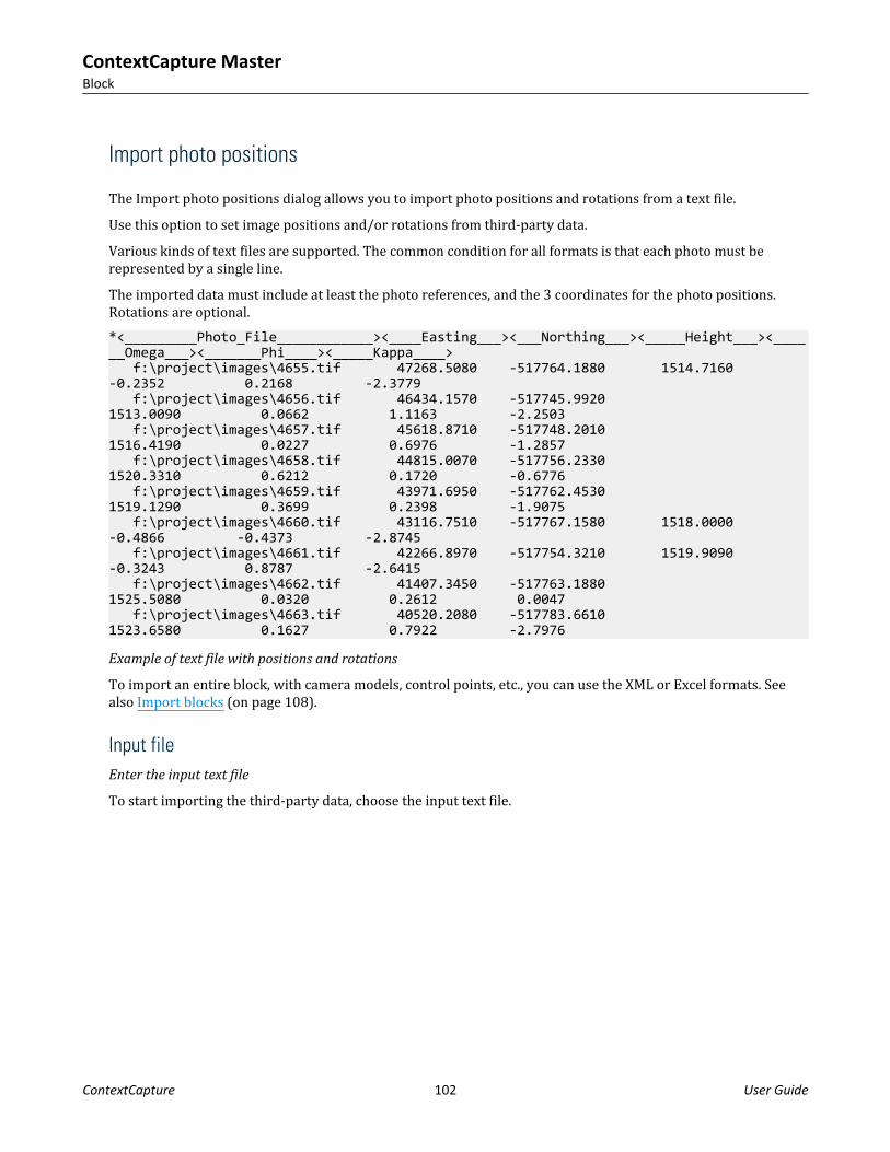
Import photo positions
The Import photo positions dialog allows you to import photo positions and rotations from a text file.Use this option to set image positions and/or rotations from third-party data.Various kinds of text files are supported. The common condition for all formats is that each photo must berepresented by a single line.The imported data must include at least the photo references, and the 3 coordinates for the photo positions.Rotations are optional.*<_________Photo_File____________><____Easting___><___Northing___><_____Height___><______Omega___><_______Phi____><_____Kappa____> f:\project\images\4655.tif 47268.5080 -517764.1880 1514.7160 -0.2352 0.2168 -2.3779 f:\project\images\4656.tif 46434.1570 -517745.9920 1513.0090 0.0662 1.1163 -2.2503 f:\project\images\4657.tif 45618.8710 -517748.2010 1516.4190 0.0227 0.6976 -1.2857 f:\project\images\4658.tif 44815.0070 -517756.2330 1520.3310 0.6212 0.1720 -0.6776 f:\project\images\4659.tif 43971.6950 -517762.4530 1519.1290 0.3699 0.2398 -1.9075 f:\project\images\4660.tif 43116.7510 -517767.1580 1518.0000 -0.4866 -0.4373 -2.8745 f:\project\images\4661.tif 42266.8970 -517754.3210 1519.9090 -0.3243 0.8787 -2.6415 f:\project\images\4662.tif 41407.3450 -517763.1880 1525.5080 0.0320 0.2612 0.0047 f:\project\images\4663.tif 40520.2080 -517783.6610 1523.6580 0.1627 0.7922 -2.7976
Example of text file with positions and rotations
To import an entire block, with camera models, control points, etc., you can use the XML or Excel formats. Seealso Import blocks (on page 108).
Input fileEnter the input text file
To start importing the third-party data, choose the input text file.
ContextCapture MasterBlock
ContextCapture 102 User Guide

Figure 54: Page Input file
File formatDefine how the input file must be read
Once the input file loaded, ContextCapture tries to make a first guess on the content of this file.You can adjust the import parameters, so that each column in the Data preview table contains meaningfulinformation:• Number of lines to ignore at the beginning of the file: defines the length of the file header, and ignores it
during import.• Delimiters: defines the column separators. Several characters can be specified.
The option Combine consecutive delimiters can be required, for instance when sequences of white spaces areused as delimiter.
• Decimal separator: dot (123.456) or comma (123,456).
ContextCapture MasterBlock
ContextCapture 103 User Guide

Figure 55: Page File format
Note: Empty lines are ignored.
Data propertiesDefine the imported data
Define the spatial reference system of imported positions and optional rotation parameters.
ContextCapture MasterBlock
ContextCapture 104 User Guide

Figure 56: Page Data properties
ContextCapture MasterBlock
ContextCapture 105 User Guide

Spatial Reference SystemSpecify the coordinate system of the imported data
For data that does not have georeferenced positions, choose Local coordinate system (with known or arbitraryunit).
Input File RotationDefine optional rotation properties.
Check this option and choose the rotation properties if the input file contains photo rotations.Rotation properties are:• Angles: angles types: Omega, Phi, Kappa, Yaw, Pitch, Roll or Heading, Pitch, Roll (deprecated).• Rotations given in a matrix form are not supported here.• Camera orientation: specification of the xy-axis of the camera sensor for pose rotation.
Possible values are: X right Y down (default), X right Y up (more frequent in photogrammetry), X left Y down, Xleft Y up, X down Y right, X down Y left, X up Y right, X up Y left.
ContextCapture MasterBlock
ContextCapture 106 User Guide

• Angle units: Degrees or Radians.
OptionsAdditional data properties options.• Set pose metadata only: Keep actual 3D pose information unchanged. This option can be used to ensure that
the imported positions and rotations will only affect the photos pose metadata property and will conservethe current pose information if any. The default behavior is to update both the photos pose property andpose metadata information with the imported positions and rotations.
FieldsSpecify columns corresponding to the imported data
You must associate each input column with its respective role.The list of possible roles adapts to the input data type. For example, if the data does not contain rotations, noangles will be proposed as a possible data type.
Figure 57: Page fields
ContextCapture MasterBlock
ContextCapture 107 User Guide

Once each data type is associated with a unique column, you can proceed to the import. ContextCapture will thentry to match each line to a photo in the block, and apply the photo details to the matched photo. If unsuccessful,an error or a warning message will alert you of the problem, and you can choose to cancel the operation.Note: The "Import positions and rotations" method can match a photo of the block with its corresponding line oftext only if the line contains the full photo name.For example, for a photo named img_0.tif , the corresponding photo reference needs to be either img_0 , orimg_0.ext , where ext is an arbitrary extension.
Import blocks
Import complete or partial blocks definition from files or from a server.Note: Importing complete block definition is the only way to handle a very large number of photos withContextCapture .The following sources are supported:• BlocksExchange XML/XMLZ format: an open exchange format specified by Bentley to import/export block
definition.BlocksExchange XML/XMLZ format (on page 119).
• MS Excel XLS format: a block definition based on Microsoft Excel XLS file.MS Excel block definition (on page 127)
• ContextCapture Orientations from ProjectWise ContextShare portal. An ATExport XML export file cannot be re-imported in ContextCapture .
ContextCapture MasterBlock
ContextCapture 108 User Guide

Figure 58: Example of imported block
Import surveys data
Import control points, user tie points and positioning constraints in the block from Surveys Data XML format.See also: Export surveys data.
Split block
Splitting a block into several sub-blocks is needed to handle imported block of aerial imagery containing a largenumber of photos (typically > 5000).
ContextCapture MasterBlock
ContextCapture 109 User Guide
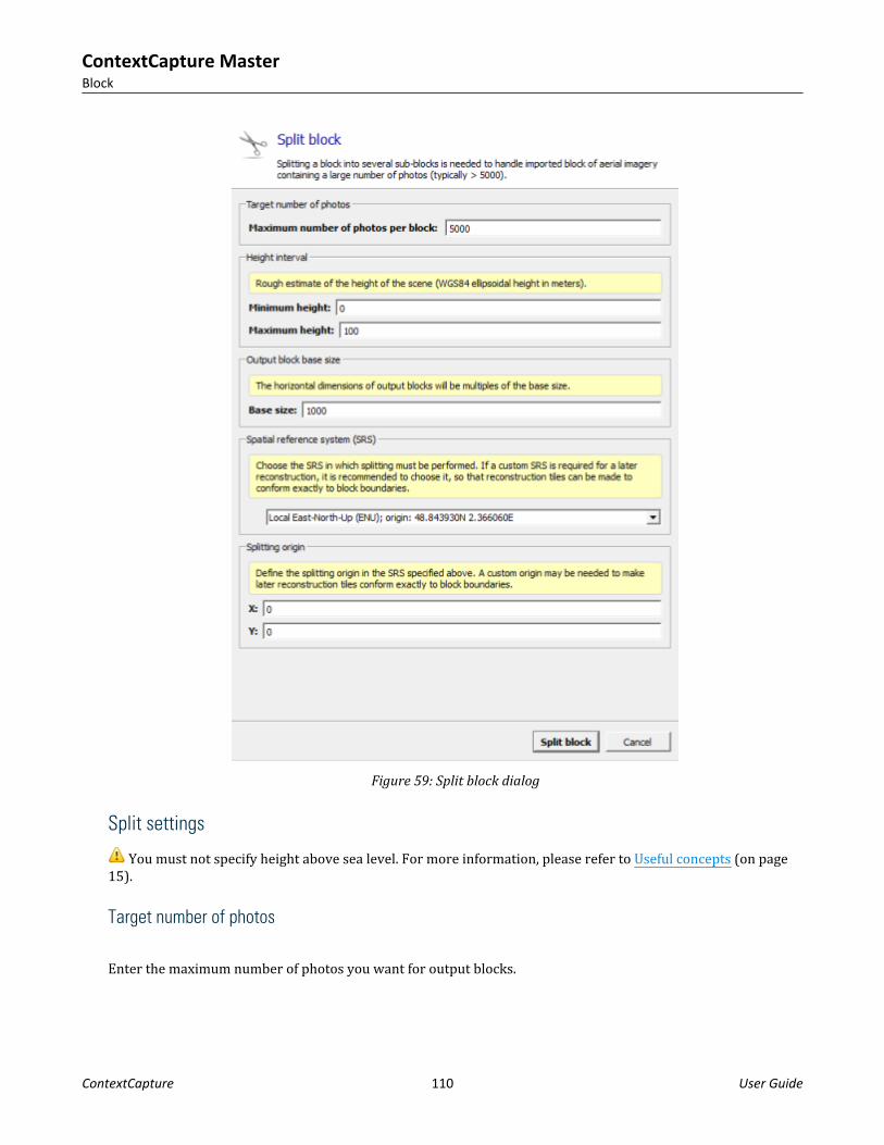
Figure 59: Split block dialog
Split settings
You must not specify height above sea level. For more information, please refer to Useful concepts (on page15).
Target number of photos
Enter the maximum number of photos you want for output blocks.
ContextCapture MasterBlock
ContextCapture 110 User Guide

Height intervalEnter the rough estimate of the scene ellipsoidal height interval.
Output block base sizeEnter the base size of output blocks. Actual dimensions of output blocks will be multiple of this base size.For instance:Base size: 500
The actual output block size may be: 500, 1000, 1500... depending on the scene contents and other split settings.
Spatial reference system (SRS)Choose the SRS in which splitting must be performed.By default, use a Local East-North-Up system with an origin set at the centroid of input block's photo positions.If a custom SRS is required for a later reconstruction, it is recommended to choose it, so that reconstruction tilescan be made to conform exactly to block boundaries.
Splitting originDefine the splitting origin in the specified SRS.A custom origin may be needed to make later reconstruction tiles conform exactly to block boundaries.
Split processingClick on Split block to start the split processing.Split divides the aerial block into several parts according to a regular 2D grid.To perform a reconstruction of all parts, you must take care on further reconstruction spatial frameworksettings in order to get compatible tiles and coordinate system.When defining a reconstruction for one block part, please define the spatial framework as follows:• Use the same SRS to define all reconstructions spatial framework.• Use regular planar grid as tiling mode• Use a tile size that divides the block size.• Use (0 ; 0), or multiples of the block size, as custom tiling origin coordinates.• Use the region of interest corresponding to the block part.Adequate reconstruction spatial framework settings are reminded in the split report and recalled in thedescription of each block part.Note: Once split, the parent block may be unloaded to save memory and loading/saving time (right click >Unload). See also Load/unload blocks (on page 117).The split process also generates a KML file useful to get an overview of computed sub-block regions.The KML file is accessible in the project folder: myBlock - sub-block regions.kml.
ContextCapture MasterBlock
ContextCapture 111 User Guide

Figure 60: Sub-block regions overview in Google Earth
Extract block
Extract a sub-block which covers a given region.
ContextCapture MasterBlock
ContextCapture 112 User Guide
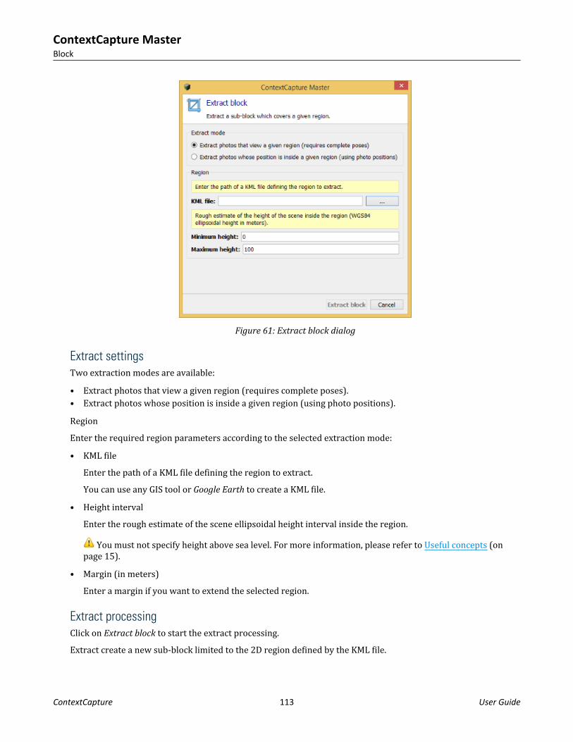
Figure 61: Extract block dialog
Extract settingsTwo extraction modes are available:• Extract photos that view a given region (requires complete poses).• Extract photos whose position is inside a given region (using photo positions).RegionEnter the required region parameters according to the selected extraction mode:• KML file
Enter the path of a KML file defining the region to extract.You can use any GIS tool or Google Earth to create a KML file.
• Height intervalEnter the rough estimate of the scene ellipsoidal height interval inside the region.
You must not specify height above sea level. For more information, please refer to Useful concepts (onpage 15).
• Margin (in meters)Enter a margin if you want to extend the selected region.
Extract processingClick on Extract block to start the extract processing.Extract create a new sub-block limited to the 2D region defined by the KML file.
ContextCapture MasterBlock
ContextCapture 113 User Guide

Note: Once extracted, the parent block may be unloaded to save memory and loading/saving time (right click >Unload).See also Load/unload blocks (on page 117).
Export
Export blockMenu Block > Export > Export block
Export block properties in various formats.
Figure 62: The export block dialog
Select the output format, output file and options; and click on Export block to create the XML file.The following output formats are supported:
• BlocksExchange XML/XMLZ format: an open exchange format specified by Bentley to import/export blockdefinition. BlocksExchange XML/XMLZ format (on page 119).XMLZ format is an extension of XML format adding file compression for convenience (zip).
• ATExport XML format: Basic export of block main properties in XML format. ATExport XML format (on page128).
The ATExport XML format is a simplified format made for exporting to 3rd party software only. You mustuse the BlocksExchange XML format if you want to later re-import blocks in ContextCapture.
Google Earth KML: Export photo positions and some other properties to a KML file.
ContextCapture MasterBlock
ContextCapture 114 User Guide

The exported KML file is suited to visualize the photo positions in a standard GIS tool or in Google Earth.• TREND-ONE XML: custom block format dedicated to TREND-ONE.According to the selected format and to block properties, following options are available:• Spatial reference system: select the coordinate system used to write 3D positions and rotations (only for a
georeferenced block).• Rotation format: select how rotations are written, Rotation matrix or Omega, Phi, Kappa angles (only for
blocks with known rotations).• Camera orientation: select the axis convention for rotations (only for blocks with known rotations).• Include automatic tie points: include automatic tie points in the export.
Exporting automatic tie points may produce heavy XML files.• Export photos without lens distortion: photos are undistorted according to the block's distortion data and
exported to JPG files in a sub-directory. Exporting photos without lens distortion may produce heavy files.
Figure 63: Example of block KML export displayed in GoogleEarth
Export surveys
Menu Block > Export > Export surveys
ContextCapture MasterBlock
ContextCapture 115 User Guide

Export control points, user tie points and constraints to various formats.• ContextCapture Surveys File: XML format is suited for exchanging surveys between blocks or projects
(including control points and user tie points with measurements and positioning constraints).• Text File [Name X Y Z]• KML file (for georeferenced blocks only): format suited to visualize the photo positions in a standard GIS tool
or in Google Earth.
Figure 64: Export surveys dialog
Export to Orbit 3DM
Create a Mapping Run for Orbit 3DM from block imagery and productions.
ContextCapture MasterBlock
ContextCapture 116 User Guide

Figure 65: Export to Orbit 3DM dialog
Select the items to include and click 'Export' to proceed.
Share on ProjectWise ContextShare
ProjectWise ContextShare is the Bentley platform to publish, manage and share reality data. You need to besigned up with your Bentley CONNECT account.A ContextCapture block is composed of three types of data:• Image collection: set of input image files for this block.• Scan collection: set of point clouds for this block.• Orientation: defining positions, rotations and optical properties of the images part of the image collection.To learn more about sharing on ProjectWise ContextShare, see Web publishing, Share on ProjectWiseContextShare (on page 181).
Load/unload blocks
Load/unload blocks from the current project.
You can make blocks temporarily unavailable within a project, and later restore them.Unload block allows to save memory and to reduce project loading time.
ContextCapture MasterBlock
ContextCapture 117 User Guide

To unload blocks from a projectIn the project tree view, select a block that you want to unload from the current project.In the block context menu (right click on the block), choose Unload.
Figure 66: Unload block from block context menu
The block is now displayed as unloaded, and its icon in the project tree view is grayed out.
To load blocks into a projectIn the project tree view, select a block that is unloaded.In the block context menu, choose Load.
The block is now available for use in the current project.
Merge blocks
Merge a selection of blocks into one new block.Define the input blocks by performing a multi-selection in the project tree view using Shift or Ctrl keys.From the selection context menu (right click), call Merge blocks.You can merge several blocks only if they use a compatible positioning level (for example, if all selected blocksare georeferenced).
ContextCapture MasterBlock
ContextCapture 118 User Guide

Figure 67: Merging a selection of blocks
BlocksExchange XML/XMLZ format
The BlocksExchange XML format is an open exchange format specified by Bentley to import/export blocksdefinition in ContextCapture Master.The XML file can include properties of one or several blocks.XMLZ format is an extension of XML format adding file compression for convenience (zip).
Format specifications<?xml version="1.0" encoding="utf-8"?><BlocksExchange version="2.1"> <!-- Definition of one or several useful spatial reference systems (SRS). --> <!-- Here, we need the French Lambert 93. --> <SpatialReferenceSystems> <SRS> <!-- In the sequel, the SRS is referred to by this ID. --> <Id>0</Id> <!-- User-friendly SRS name. --> <Name>Lambert 93</Name> <!-- The spatial reference system definition can be either a Well Known Text definition (e.g. WGS84), "EPSG: ", a PROJ.4 definition, or the path to a file containing such a definition. --> <Definition>EPSG:2154</Definition> </SRS> </SpatialReferenceSystems> <!-- Optional: a path to prefix image paths when they are not absolute (default: use the directory of the exchange file). --> <BaseImagePath>D:\data\Paris2012sample\Images</BaseImagePath> <!-- Block definition. A single file can define several blocks. --> <Block> <!-- Block name and description are optional. --> <Name>Paris2012</Name> <Description>Small sample of the Paris 2012 dataset</Description> <!-- The type of block is optional. Supported types are: Aerial, Nadir and Orbit. --> <Type>Aerial</Type> <!-- Photo downsampling rate can be optionally provided with <PhotoDownsamplingRate> tag --> <!-- Minmum and maximum viewing distance can be optionally provided with <MinimumViewingDistance> and <MaximumViewingDistance> tags --> <!-- ID of the base SRS used in the block. By default, the spatial reference system is assumed to be a local Cartesian coordinate system. -->
ContextCapture MasterBlock
ContextCapture 119 User Guide

<SRSId>0</SRSId> <Photogroups> <!-- All photos taken using the same physical camera, with identical focal length and dimensions must be gathered in a photogroup. --> <Photogroup> <!-- Optionally, a different spatial reference system can be specified for each photogroup with the <SRSId> tag. By default, the SRS of the block is assumed. --> <!-- Optionally, a name with the <Name> tag, and a description with a <Description> tag. --> <Name>UCX</Name> <!-- Image dimensions, in pixels. --> <ImageDimensions> <Width>9420</Width> <Height>14430</Height> </ImageDimensions> <!-- Optional camera model type Perspective or Fisheye (Perspective type is used if this tag is unspecified). --> <CameraModelType>Perspective</CameraModelType> <!-- Optional camera model band Visible or Thermal (Visible type is used if this tag is unspecified). --> <CameraModelBand>Visible</CameraModelBand> <!-- Sensor's largest dimension, in millimeters. --> <!-- Sensor's pixel size, in millimeters, can be substituted for this field. --> <!-- For this dataset, it would be: --> <!-- <PixelSize>0.0072</PixelSize> --> <SensorSize>103.896</SensorSize> <!-- Focal length, in millimeters. This can be either the nominal specification or a closer estimate. --> <FocalLength>100.735601903992</FocalLength> <!-- Optionally, focal length, in pixels. Can replace FocalLength and SensorSize data. --> <!-- For this dataset, it would be: --> <!-- <FocalLengthPixels>13991.05582</FocalLengthPixels> --> <!-- Optionally, specification of the xy-axis of the camera sensor for pose rotation and for any position given in millimeter (i.e. <PrincipalPoint> and <Measurement> when using <xmm> and <ymm>) --> <!-- Possible values: XRightYDown (default), XRightYUp (more frequent in photogrammetry), XLeftYDown, XLeftYUp, XDownYRight, XDownYLeft, XUpYRight, XUpYLeft --> <CameraOrientation>XRightYDown</CameraOrientation> <!-- Principal point, with respect to the sensor center. This field is optional: by default, the sensor center is used as an initial estimate of the principal point. --> <PrincipalPoint> <!-- 2D image position of the principal point, in pixels. The origin is the center of the upper-left image pixel, the x-axis is oriented to the right side of the image, and the y-axis is oriented to the bottom of the image. --> <x>4683.755692</x> <y>7223.0141002</y> <!-- Alternatively, a 2D position with respect to the sensor center can be specified, in millimeters. In this case, the xy-axis are oriented according to CameraOrientation. --> <!-- For this dataset, it would be: -->
ContextCapture MasterBlock
ContextCapture 120 User Guide

<!-- <xmm>-0.1853590176</xmm> --> <!-- <ymm>0.06130152144</ymm> --> </PrincipalPoint> <!-- Lens distortion coefficients. This field is optional: by default, no distortion is assumed as an initial estimate. --> <!-- Distortion coefficients correspond to the classical Brown's distortion model, as described in http://en.wikipedia.org/wiki/Distortion_(optics). --> <Distortion> <K1>-0.0010041516639</K1> <K2>0.0056007056563</K2> <K3>-0.009874171117100001</K3> <P1>0</P1> <P2>0</P2> </Distortion> <!-- Fisheye focal matrix used only for the camera model type Fisheye. --> <FisheyeFocalMatrix> <M_00>1960</M_00> <M_01>0</M_01> <M_10>0</M_10> <M_11>1960</M_11> </FisheyeFocalMatrix> <!-- Fisheye distortion coefficients used only for the camera model type Fisheye. --> <FisheyeDistortion> <P0>0</K1> <P1>1</K2> <P2>0</K3> <P3>0</P1> <P4>0</P2> </FisheyeDistortion> <Photo> <!-- The ID of a photograph must be unique over the whole block (in other words, even across other photogroups). --> <Id>146</Id> <!-- Path of the image. If not absolute, it is considered to be relative to BaseImagePath if defined, or otherwise to the directory of the exchange file. --> <ImagePath>071_2810.jpg</ImagePath> <!-- Optional path of the image mask. If not absolute, it is considered to be relative to BaseImagePath if defined, or otherwise to the directory of the exchange file. --> <!-- <MaskPath>071_2810_msk.jpg</MaskPath> --> <!-- Exterior orientation of the camera, as estimated by navigation devices or aerotriangulation. This field is optional. --> <!-- Optional component Id: 1 is the main component (default), 0 is no component. Photos with incomplete pose cannot belong to the main component --> <!-- <Component>1</Component> --> <Pose> <!-- 3D rotation of the camera in the spatial reference system defined above. --> <!-- It defines the rotation matrix transforming world
ContextCapture MasterBlock
ContextCapture 121 User Guide

coordinates (in the specified SRS) into camera coordinates (with axes defined by the CameraOrientation of the photogroup). --> <!-- The rotation is optional: the pose can be limited to the 3D position of the camera center (e.g. when GPS position only is available). --> <Rotation> <!-- It can be specified in one of the four representations below: --> <!-- 1. A 3x3 matrix, using the <M_ij> tags, where M_ij denotes the coefficient of the (i+1)th row and the (j+1)th column of the rotation matrix. --> <M_00>-0.9999982912233401</M_00> <M_01>-0.001636319085375301</M_01> <M_02>-0.0008602425863163225</M_02> <M_10>-0.001631068695467463</M_10> <M_11>0.9999802528616577</M_11> <M_12>-0.00606906089589293</M_12> <M_20>0.0008701565192966738</M_20> <M_21>-0.006067647409696231</M_21> <M_22>-0.9999812130648239</M_22> <!-- 2. Omega/Phi/Kappa angles, in degrees, using the <Omega>, <Phi>, <Kappa> tags. Please refer to the formula in the camera model document. --> <!-- For this dataset, it would be: --> <!-- <Omega>179.6523471469934</Omega> --> <!-- <Phi>0.04985630236313049</Phi> --> <!-- <Kappa>179.9065465708369</Kappa> --> <!-- 3. Heading/Pitch/Roll angles, in degrees using the <Heading>, <Pitch>, <Roll> tags. Please refer to the formula in the camera model document. --> <!-- 4. Yaw/Pitch/Roll angles, in degrees using the <Yaw>, ,Pitch>, <Roll> tags. Please refer to the formula in the camera model document. --> </Rotation> <!-- 3D position of the camera center in the spatial reference system defined above. --> <!-- Depending on the SRS, x/y may stand either for longitude/latitude, for map projection coordinates, or for something else. --> <!-- Depending on the SRS, z may stand either for a geoid height, for an orthometric height, or for something else. --> <Center> <x>651999.7159189156</x> <y>6863073.633923346</y> <z>1318.897690166719</z> </Center> </Pose> <!-- Optional depth information can be provided with <NearDepth>, <MedianDepth>, and <FarDepth> tags --> <!-- Optional Exif data (each exif data property is optional) --><!-- <ExifData> <ImageDimensions> <Width>4000</Width> <Height>3000</Height>
ContextCapture MasterBlock
ContextCapture 122 User Guide

</ImageDimensions> <PixelDimensions> <Width>0.02</Width> <Height>0.02</Height> </PixelDimensions> <GPS> <Latitude>45.5686684</Latitude> <Longitude>2.6551104</Longitude> <Altitude>1589.5469</Altitude> </GPS> <FocalLength>24</FocalLength> <FocalLength35mmEq>36</FocalLength35mmEq> <Make>FUJIFILM</Make> <Model>FinePix S3Pro</Model> <LensModel>FinePix S3Pro</LensModel> <DateTimeOriginal>2015-04-29T06:40:26</DateTimeOriginal> </ExifData> --> </Photo> ... </Photogroup> </Photogroups> <!-- Control points are highly recommended for accurate positioning. --> <ControlPoints> <!-- Optionally, a different spatial reference system can be specified with the <SRSId> tag. By default, the SRS of the block is assumed. --> <ControlPoint> <!-- Control point name and description are optional. --> <Name>Control point #1</Name> <!-- Optionally, a different spatial reference system can be specified for each control point with the <SRSId> tag. By default, the SRS of the control points container is assumed. --> <!-- 3D position of the control point in the active spatial reference system. --> <!-- Depending on the SRS, x/y may stand either for longitude/latitude, for map projection coordinates, or for something else. --> <!-- Depending on the SRS, z may stand either for a geoid height, for an orthometric height, or for something else. --> <Position> <x>652788.0525588237</x> <y>6863015.362218254</y> <z>78.07000000122935</z> </Position> <!-- Image measurements. --> <Measurement> <!-- ID of the photo where the measurement is taken. The measurements of a control point must have different photo IDs. --> <PhotoId>151</PhotoId> <!-- 2D image position of the measurement, in pixels. The origin is the center of the upper-left image pixel, the x-axis is oriented to the right side of the image, and the y-axis is oriented to the bottom of the image. --> <!-- Alternatively, a 2D position with respect to the principal point, in millimeters. In this case, the xy-axis are oriented according to the CameraOrientation of the corresponding photogroup. -->
ContextCapture MasterBlock
ContextCapture 123 User Guide

<!-- For this dataset, it would be: --> <!-- <xmm>18.6231910176</xmm> --> <!-- <ymm>-4.48973352144</ymm> --> <x>7270.31</x> <y>6599.44</y> </Measurement> ... </ControlPoint> <ControlPoint> <Name>Control point #2</Name> <Position> <x>652123.2211166573</x> <y>6863245.976366176</y> <z>80.07999999914318</z> </Position> <!-- If specified, a control point may be a check point (default: false)--> <CheckPoint>true</CheckPoint> <!-- If specified, a control point may have accuracies --> <HorizontalAccuracy>0.01</HorizontalAccuracy> <VerticalAccuracy>0.10</VerticalAccuracy> <Measurement> <PhotoId>146</PhotoId> <x>3296.56</x> <y>9253.75</y> </Measurement> ... </ControlPoint> <ControlPoint> <Name>Control point #3</Name> <!-- If specified, a control point might be Full (default), Horizontal or Vertical --> <Category>Horizontal</Category> <Position> <!-- no z position --> <x>652365.1205012415</x> <y>6863549.148163618</y> </Position> <HorizontalAccuracy>0.01</HorizontalAccuracy> <!-- no vertical accuracy --> <Measurement> <PhotoId>95</PhotoId> <x>3178.26</x> <y>4020.21</y> </Measurement> ... </ControlPoint> ... </ControlPoints> <!-- Known tie points may be used to refine an aerotriangulation. --> <!-- Uncomment this section before import to get a single tie point in the imported block. Please note that a reconstruction created from a such block will fail. --> <!--<TiePoints> --><!-- Optionally, a different spatial reference system can be specified with the <SRSId> tag. By default, the SRS of the block is assumed. --><!-- <TiePoint> --><!-- Tie point name and description are optional. --><!--
ContextCapture MasterBlock
ContextCapture 124 User Guide

--><!-- Optionally, a different spatial reference system can be specified for each tie point with the <SRSId> tag. By default, the SRS of the tie points container is assumed. --><!-- --><!-- Optional 3D position of the tie point in the active spatial reference system. --><!-- --><!-- Depending on the SRS, x/y may stand either for longitude/latitude, for map projection coordinates, or for something else. --><!-- --><!-- Depending on the SRS, z may stand either for a geoid height, for an orthometric height, or for something else. --><!-- <Position> <x>652119.8871409688</x> <y>6863304.305716386</y> <z>87.79328384995461</z> </Position> --><!-- Optional tie point color. --><!-- <Color> <Red>0.59</Red> <Green>1.0</Green> <Blue>0.0</Blue> </Color> --><!-- Image measurements. --><!-- <Measurement> --><!-- Optional measurement type User or Automatic (Automatic type is used if this tag is unspecified). --><!-- <Type>Automatic</Type> --><!-- ID of the photo where the measurement is taken. The measurements of a tie point must have different photo IDs. --><!-- <PhotoId>146</PhotoId> --><!-- 2D image position of the measurement, in pixels. The origin is the center of the upper-left image pixel, the x-axis is oriented to the right side of the image, and the y-axis is oriented to the bottom of the image. --><!-- --><!-- Alternatively, a 2D position with respect to the principal point, in millimeters. In this case, the xy-axis are oriented according to the CameraOrientation of the corresponding photogroup. --><!-- <x>3324.26001</x> <y>9930.269531</y> </Measurement> <Measurement> <PhotoId>158</PhotoId> <x>9079.006836000001</x> <y>9902.772461000001</y> </Measurement> <Measurement> <PhotoId>162</PhotoId> <x>6240.366211</x> <y>9896.118164</y> </Measurement> </TiePoint> </TiePoints>--> <!-- Optional block's positioning constraints based on user tie point (0
ContextCapture MasterBlock
ContextCapture 125 User Guide

based indices). --> <!-- Each constraint is optional. --> <!--<PositioningConstraints> <OriginConstraint> <O>2</O> </OriginConstraint> <ScaleConstraint> <A>0</A> <B>3</B> <DistanceAB>56.350</DistanceAB> </ScaleConstraint> <AxisConstraint> <A>0</A> <B>3</B> <AxisAB>z</AxisAB> --><!-- x, y, or z --><!-- </AxisConstraint> <OrientationConstraint> <A>0</A> <B>3</B> <C>2</C> <AxisAB>z</AxisAB> --><!-- x, y or z --><!-- <AxisSideC>upperX</AxisSideC> --><!-- lowerX, upperX, lowerY, upperY, lowerZ, or upperZ --><!-- </OrientationConstraint> </PositioningConstraints>--><PointClouds> <PointClouds> <PointCloud> <Name>PointCloud name</Name> <Description>Description of the pointcloud</Description> <Path>Absolute or relative path to the POD pointcloud file</Path> <CreatedDateTime>2017-05-26T15:59:08</CreatedDateTime> <SRS>SRS definition</SRS> (can be empty) <BoundingBox> <XMin></XMin> <XMax></XMax><YMin></YMin> <YMax></YMax> <ZMin></ZMin> <ZMax></ZMax> </BoundingBox><MinResolution>0.0232077879728498</MinResolution> <MedResolution>0.0480807854162596</MedResolution> <MeanResolution>0.0779783209951879</MeanResolution> <MaxResolution>4.71837838822922</MaxResolution><ColorMode></ColorMode><!-- UseIntensity or UseColor or None --><Scans> <Scan> <Name>Scan name</Name> <NumPoints>320519</NumPoint> <Attributes>2</Attributes> <!-- If static scan --> <SourcePosition> <x>0.05</x> <y>18.59</y> <z>58.369</z> </SourcePosition>
ContextCapture MasterBlock
ContextCapture 126 User Guide

<!-- If mobile scan --> <Trajectories> <Trajectory> <Point> <x>0.05</x> <y>18.59</y> <z>58.369</z> </Point> … </Trajectory> <Trajectories> </Scan></Scans </PointCloud> </PointClouds></Block></BlocksExchange>
You can find the above example and specification file in ContextCapture installation directory:For more information about ContextCapture camera model, see also ContextCapture camera model (on page217).
MS Excel block definition
Blocks definition can be provided in MS Excel documents according to a format specified by Bentley.This format is provided for convenience to ease block import from pre-existing MS Excel documents in XLS orXLSX format. However, we recommend you to use the more flexible BlocksExchange XML/XMLZ format (on page119) in the general case.In an MS Excel file, the block definition can be partial or complete, and data can be provided in different form.You can find an example and a template in ContextCapture installation directory:• doc/BlockImportSample.xls• doc/BlockImportTemplate.xls
Data worksheetsIn the MS Excel file, the data is provided in several worksheets.
XLS format is limited to 16384 rows, use XLSX format instead if you want to import larger dataset.Photogroups
List of photogroups with corresponding parameters:• Name: unique name of this Photogroup (mandatory)• Width, Height: image size in pixels (mandatory)• FocalLength: focal length in mm (mandatory)• SensorSize or PixelSize: in mm (mandatory)• PrincipalPointX, PrincipalPointY: principal point position in pixels (optional)• PrincipaPointlXmm, PrincipalPointYmm: principal point position in mm (optional)• CameraOrientation: camera orientation reference, see BlocksExchange XML/XMLZ format (on page 119)
(optional)
ContextCapture MasterBlock
ContextCapture 127 User Guide

• K1, K2, K3, P1, P2: lens distortion coefficients (optional)Photos
List of photos with corresponding parameters:• Name: file name (mandatory)• PhotogroupName: name of the attached camera (mandatory)• Directory: base directory (optional)• Extension: file suffix (optional)• Longitude, Latitude, Height or Easting, Northing, Height: 3D position (optional)• Omega, Phi, Kappa or Yaw, Pitch, Roll, or Heading, Roll, Pitch: rotation, in degrees or radians according to
options (optional)Photo Name can be an absolute path, a relative path, or a file name:The actual photo path is built using optional option BaseImagePath, optional photo Directory, photo Name, andoptional Extension .ControlPoints
List of control points with name and 3D position.To provide control points measurements, use the BlocksExchange XML/XMLZ format (on page 119) instead.Options
Options used to interpret the MS Excel file.SRS
Spatial reference system used to interpret 3D positions and rotations.
Supports EPSG code ("EPSG:XXX"), PROJ.4 or WKT definition.InRadians
Specify that orientation angles are provided in radians rather than in degrees.BaseImagePath
Optional base directory used to build photos absolute path.BlockType
Optional block type.
ATExport XML format
The ATExport XML format contains interior and exterior orientation data for each photo:• ImagePath: image file path,• ImageDimensions: image width and height in pixels,• CameraModelType: Perspective or Fisheye,• FocalLength: focal length in pixels,• FisheyeFocalMatrix: focal matrix in pixels used only for the camera model type Fisheye,• AspectRatio: image aspect ratio,• Skew: image skew,• PrincipalPoint: principal point position in the image in pixels,
ContextCapture MasterBlock
ContextCapture 128 User Guide

• Distortion: lens distortion coefficients used only for the camera model type Perspective,• FisheyeDistortion: lens distortion coefficients used only for the camera model type Fisheye,• Rotation: photo rotation (if georeferenced, given in ECEF),• Center: photo position (if georeferenced, given in ECEF).• Skew: skew coefficient defining the angle between x and y pixel axes.• Aspect ratio: different from 1 if the pixel are not square.
The ATExport XML format is made for exporting to 3rd party software only. You must use the BlocksExchange XML/XMLZ format (on page 119) if you want to later re-import blocks in ContextCapture.
Camera database
The camera database manages the list of camera models that ContextCapture applies automatically when addingphotos, or that you can explicitly apply on photogroups.
Figure 68: The camera database dialog
The camera database contains two kinds of items:• ContextCapture items are default camera models provided by ContextCapture . These items are read-only
and the item list is updated daily by the ContextCapture support team.• User items are camera models you added or imported on your computer.Each camera model is made of a name (alias), a date (last modified), various (optional) optical properties, andsearch/matching criteria.For more information about the optical properties, see Photogroups (on page 49).
ContextCapture MasterBlock
ContextCapture 129 User Guide

Figure 69: The camera model dialog
Apply a camera model from the database
Apply a camera model automatically when adding photosWhen adding photos from the block's Photos tab, ContextCapture automatically uses the camera database to getthe best camera model for the added photos.ContextCapture uses input photos properties (Exit data and image dimensions) to find the best camera model inthe database according to its properties and matching criteria.Note: More recent items and user items are used in priority.
Apply a camera model manually to a photogroupSee Apply a camera model manually to a photogroup (on page 130) for additional information.
Apply a camera model manually to a photogroup
Once photos are added, it is also possible to get a camera model manually from the database for a givenphotogroup:1. Right click on the photogroup and call Get camera model from the database.
ContextCapture MasterBlock
ContextCapture 130 User Guide

Figure 70: Accessing the camera database from a photogroup2. In the Camera database dialog, use the provided filters to search for a suitable camera model.
ContextCapture MasterBlock
ContextCapture 131 User Guide

Figure 71: Searching a camera model in the camera database dialog3. Click on OK to apply the selected camera model to the photogroup.
Manage the user camera databaseThere are two ways of accessing and managing the user camera database:• At photogroup level, from the block's Photos tab. This access mode allows you to quickly add the
photogroup's camera model to the database.• At application level, from the ContextCapture options: menu Options > Manage camera database. This mode
can be used for more complex operations, such as edition or deletion of previously added camera models.
ContextCapture MasterBlock
ContextCapture 132 User Guide

Figure 72: Importing/exporting user camera database
Adding the camera model of a photogroupSee Adding the camera model of a photogroup (on page 133) for additional information.
Editing the camera databaseThe camera database dialog can be accessed from the ContextCapture options: menu Options > Manage cameradatabase. Using this dialog, new user items can be added, and existing items can be edited or deleted.Please note that ContextCapture items are not editable.
Import/export user camera databaseTo save your customized items, or to move them to another computer, you can use the import/export functionsavailable from the tool menu.
Adding the camera model of a photogroup
1. Right click on the photogroup and call Add camera model to the database.
ContextCapture MasterBlock
ContextCapture 133 User Guide

Figure 73: Adding a photogroup camera model to the database2. Check the optical properties and enter an appropriate name (alias).
3. Click on OK to add the camera model to the user camera database.User-added camera models are automatically used by ContextCapture when adding new photos taken with thesame camera. For this, ContextCapture relies on the camera model's matching criteria.
ReconstructionA Reconstruction item manages a framework to create 3D reconstruction or orthophoto/DSM (spatial referencesystem, region-of-interest, tiling, constraints, retouching, processing settings). Based on the reconstruction item,one or several productions can be launched.
ContextCapture MasterReconstruction
ContextCapture 134 User Guide

Two reconstruction types are available:• 3D reconstruction: true 3D model suited for reality mesh and by-products creation.• Orthophoto/DSM: simplified 2.5D model dedicated to high quality orthophoto and DSM creation from
photos.
Figure 74: The reconstruction interface
The reconstruction is defined by the following properties:• Spatial framework (on page 137) defines spatial reference system, region of interest and tiling. It also
includes resolution settings for an orthophoto/DSM.• Geometry constraints (on page 141) allows the use of existing 3D data to control the reconstruction and to
avoid reconstruction errors.• Reference model (on page 142) is the reconstruction sandbox, it stores a model in native format which is
progressively completed as productions progress. This reference model is the model to which retouches andreconstruction constraints are applied, and from which future productions are derived.
• Processing settings (on page 144) sets geometric precision level (high, extra, etcetera) and otherreconstruction settings.
• List of productions.Note: Spatial framework and processing settings must be edited before starting the production. Once theproduction is started the Spatial framework tab is read-only. In this case, you can clone the reconstruction to geta new fully editable reconstruction framework.
ContextCapture MasterReconstruction
ContextCapture 135 User Guide

General
The General tab manages the reconstruction dashboard and the list of productions.
DashboardThe dashboard provides information on the status of the reconstruction as well as on the main spatialframework settings.
Figure 75: Reconstruction dashboard
ProductionsList of productions of the reconstruction.
Figure 76: Reconstruction productions
Several productions can be generated from a same reconstruction. They will share same reconstruction settings(SRS, tiling, region of interest, processing settings, ...).Some operations can be executed from the reconstruction General tab:
Submit a new production on ContextCapture Engine or on ContextCapture Cloud service.
See Creating a new production (on page 159) and Process on the cloud (on page 100).
Remove production from the list.
ContextCapture MasterReconstruction
ContextCapture 136 User Guide

This only removes references to the production from the project. The output files of the production, if any, arenot affected.See Production (on page 158) also for more details on productions.
Spatial framework
The Spatial framework tab is dedicated to the definition of the reconstruction 3D workspace, including spatialreference system, region of interest and tiling.Note: The Spatial framework must be edited before starting the production. Once the production is started, theSpatial framework tab is read-only.
Spatial reference system (SRS)Available only for georeferenced project, defines the coordinate system used by the Spatial framework, for bothRegion of interest and Tiling.
Any well-known SRS definition can be entered, see Spatial reference system (on page 192).By default, the reconstruction uses a Local East-North-Up (ENU) system with an origin set on the center of themodel.Some SRS define both the coordinate system and tiling. It is the case for Spatial framework (on page 137).For non-georeferenced projects, the reconstruction uses the block local coordinate system.The reconstruction Spatial reference system is used as reference for region of interest and tiling, whereas output3D model coordinates of productions depend on another Spatial reference system, which you can select atproduction level.
Resolution (orthophoto/DSM)
ContextCapture MasterReconstruction
ContextCapture 137 User Guide

For a reconstruction of type n orthophoto/DSM reconstruction-type, defines the target resolution for thereference orthophoto/DSM.
Region of interestDefines the maximum area of the reconstruction.
The Region of Interest is set thanks to an axis-aligned 3D box in the spatial reference system of thereconstruction.By default, the region of interest automatically focuses on areas of significant resolution: in each photograph,statistics on the resolution of the block tie points are computed, and points in the core of the distribution areselected. The region of interest is defined as the bounding box of these selected block tie points. The Resetbounds… button allows to reset the region of interest to the above default settings (Smart mode), or to thebounding box of the block tie points, obtained after rejecting gross outliers only (Maximal mode). The Maximalmode is likely to include distant background areas in the region of interest and to require some manualadjustment of the region of interest.
Edit region of interest
Click on this button to edit the region of interest interactively in the 3D view.Move bounding box faces to set the region of interest.
ContextCapture MasterReconstruction
ContextCapture 138 User Guide

Figure 77: Interactive edition of the region of interest
An extruded polygon can be used to define the area more precisely from a DGN or from a KML file (ifreconstruction is georeferenced). Click on the button Import from polygon to specify the region of interest froma KML or a DGN file. The polygon file only defines a 2D polygon: top and bottom height can be defined from theinterface.Note: It is sometimes relevant to define a region of interest which is smaller than the default bounding box (forexample, to discard distant background areas from the reconstruction, when the Smart mode does not detectthem automatically). However, in some cases, notably when the block tie points do not cover some interestingparts of the scene (for instance, a high isolated building), it is useful to enlarge the default region of interest.
TilingSelect how to divide the reconstruction task.
3D models generated by ContextCapture can span entire cities and hence may not fit in your computer's memoryin one piece. Thus, it is often necessary to divide them into tiles.
ContextCapture MasterReconstruction
ContextCapture 139 User Guide

Four tiling modes are available:• No tiling: Do not subdivide reconstruction.• Regular planar grid: Divide reconstruction into square tiles along the XY plane.• Regular volumetric grid: Divide reconstruction into cubic tiles.• Adaptive tiling: Adaptively subdivide reconstruction into boxes to meet a target memory usage. This is
particularly useful to reconstruct a 3D model with a highly non uniform resolution, e.g. when reconstructinga city from aerial images and ground images of a few landmarks. In such a case, it is not possible to find aregular grid size adequate for all areas.
Tiling optionsWhen using a tiling other than an adaptive tiling, select tile size and tiling origin (click on Advanced options)depending on your needs.Tiling is aligned to the selected spatial reference system. Tiles are discarded if they are completely outside of theregion of interest, or if they do not contain any block tie point.By default, tiles not containing any tie point are discarded from the tiling, enable the option Discard empty tilesto keep all tiles in the specified region of interest.Note: To preview the tiling in the 3D view, choose Tiling in the Show combo-box.For georeferenced reconstructions, tiling can be exported in KML format (menu Reconstruction > Tiling > Exportto KML ...) to get an overview of the spatial framework in a standard GIS tool or in Google Earth.
ContextCapture MasterReconstruction
ContextCapture 140 User Guide

Figure 78: Tiling overview in Google Earth
Bing Maps Tile SystemContextCapture allows to perform reconstruction following the Bing Maps Tile System.Select a Bing Maps spatial reference system to setup a reconstruction using a Bing Maps coordinate system andtiling for a given level.
Geometry constraints
The Geometry constraints tab allows the use of existing 3D data to control the reconstruction and avoidreconstruction errors.
Geometry constraints are available only in ContextCapture Center Edition. See Software Editions (on page 27).In some cases, the automatic reconstruction may have reconstruction errors that need to be fixed. It may occurfor instance on unseen areas, on reflective parts or on water surfaces.Rather than fixing problems after the reconstruction with a 3rd party tool (refer to Retouching (on page 187)),ContextCapture can consider existing 3D data to help the reconstruction process on areas where photos are notsufficient.
ContextCapture MasterReconstruction
ContextCapture 141 User Guide

Figure 79: Reconstruction constraints tab
You can define geometry constraints at any time during the workflow. If the reference model already exists, tilesoverlapping the reconstruction constraint will be reset: they will be recomputed in later productions, by takinginto account the new geometry constraints.ContextCapture can use geometry constraints defined from:• A KML or a DGN file containing 3D polygons (only for georeferenced reconstructions),• An OBJ or a GDN file containing a 3D mesh.
For georeferenced project, the imported file can use any spatial reference system. Please select the spatialreference system and the origin accordingly.For non georeferenced projects, the spatial reference system of the input file must correspond to that of theinternal reconstruction.
ContextCapture uses this data as a soft constraint in the reconstruction process: a reconstruction constraint isused only if there is no other reliable data in the area: wherever reliable 3D information can be inferred frominput photos, it will override the reconstruction constraint.Note: It is often much more efficient to create constraints in a GIS software (based on an existing ortho-image forinstance) than to fix errors of the automatically produced 3D model in a 3D modeling software.
Reference model
The Reference model tab manages the internal model of the reconstruction. It allows you to control modelquality, to apply retouches or reset the reconstruction.
ContextCapture MasterReconstruction
ContextCapture 142 User Guide

Figure 80: Reference 3D model tab
The reference model is the reconstruction sandbox. It stores internally a model which is progressivelycompleted as productions progress, to which retouches can be applied, and from which future productions arederived.The reference model is managed tile by tile, and each tile can be controlled individually.An Unprocessed tile without retouch becomes Completed as soon as a production including this tile is complete.
Model contentsFor a 3D reconstruction, a tile is made of a textured 3D mesh in native format ; for an orthophoto/DSM, a tile ismade of a DSM file and and orthophoto file in TIF format.Tiles of a 3D reconstruction may be displayed individually in ContextCapture Viewer: from the tile context menu(right click), choose Open tile with ContextCapture Viewer.
Figure 81: Tile context menu
Note: To ease quality control of a 3D reconstruction, it is advised to perform a first complete production in 3MXor S3C formats: 3MX and S3C formats include dynamic level-of-detail and paging and allows you to smoothlynavigate the entire reconstruction in ContextCapture Viewer or in the integrated Quality control interface.To manage the reference model, the following features are proposed:• Touchup (on page 149): Fix the current reference model with retouches.• Reset (on page 154) Clear a selection of the reference model, so that it is recomputed by later productions.
ContextCapture MasterReconstruction
ContextCapture 143 User Guide

• Software Editions (on page 27): Inspect and tag reference model tiles.• Inter-tile color equalization (on page 155).
Processing settings
The Processing settings tab allows you to choose reconstruction processing settings, including geometricprecision and advanced settings.Note: Processing settings must be edited before starting the production. Once the production is started theProcessing settings tab is read-only.
Figure 82: Processing settings tab
Selection of matching pairsThis advanced option allows you to optimize the matching pair algorithm for your particular input imagedataset:• Generic (default): advised for most image datasets.• For structured aerial flight: advised for structured aerial image datasets only, acquired with a regular sweep
of the area in parallel lines, and sensors with fixed lever arm angles.• Focus on ROI: advised for vertical structure captured following orbit path.
Photos used for geometry
This advanced option allows you to choose the input data used for reconstructing geometry.• Exclude thermal imagery: advised when thermal imagery resolution is not sufficient for photogrammetry. In
this case, only photos with visible colors band are used for geometry. This is the default whenever photoswith visible colors are available.
ContextCapture MasterReconstruction
ContextCapture 144 User Guide

• Include thermal imagery: geometry will use all available photos.• None: geometry will use only point clouds (available only if input block has point clouds).
Geometric precisionThis option specifies the tolerance level in input photos, which results in more or less detail in the computed 3Dmodel:• Ultra: ultra high precision. Warning: highly memory and computation time consuming, not recommended for
large areas.• Extra (default): extra precision, larger file size (tolerance of 0.5 pixel in input photos).• High: high precision, smaller file size (tolerance of 1 pixel in input photos).• Medium: medium precision, best suited for Orthophoto/DSM productions (tolerance of 2 pixels in input
photos). The fastest and most memory-efficient mode.
Computation time and memory requirementsHigh and Extra modes are similar in terms of computation time and memory consumption.Ultra mode is 4 times slower, and takes 4 times more memory than High or Extra mode.Medium mode is 2-3 times faster, and takes 4 times less memory than High or Extra mode.
Hole-fillingThis option gives you control over the hole-filling algorithm:• Fix small holes only (default): advised for most datasets.• Fix all holes except at tile boundaries: reinforce the hole-filling algorithm to minimize the number of holes in
the mesh. With this option, the algorithm tries to enforce a closed surface.Note: This last option may create aberrant geometry to fill large holes. However, retouching these aberrantparts may be easier than filling unwanted holes.
Geometric simplification• Standard (default): standard geometric simplification based on mesh decimation.• Planar: geometric simplification based on plane detection.
This algorithm strives to find planar surfaces (like walls and roofs) and ensures they remain planar duringthe reconstruction and simplification stages.The planar simplification is based on a tolerance threshold:If provided in pixels, the tolerance is defined in pixels in input photos: the simplification depends on inputphotos resolution.If provided in meters (or units for non-georeferenced blocks), the tolerance is defined in the 3D coordinatespace: the simplification is uniform over the 3D model.
ContextCapture MasterReconstruction
ContextCapture 145 User Guide

3D reconstruction of an area, without (top) and with (bottom) planar simplification.
Color equalization modeContextCapture generates the 3D model texture from various input photos that may have been acquired indifferent lighting conditions.To reduce radiometric differences between input photos in the 3D model texture, ContextCapture proposes twoways to automatically perform color equalization on the input photos.This color equalization mode option lets you change the color equalization algorithm used to process thetexture:• Standard: the default advanced ContextCapture automatic color equalization performed on each tile
independently.• Blockwise: a new color equalization algorithm, generally more flexible than the standard algorithm, and able
to deal with greater radiometric differences between images. Note that this automatic equalization is
ContextCapture MasterReconstruction
ContextCapture 146 User Guide

computed during the aerotriangulation for all input photos. This dispenses with the need for a second, inter-tile color equalization, sometimes needed in the Standard method.To have this option activated, you need to enable Blockwise color equalization in the aerotriangulationsettings.
• Standard (including thermal): This mode will apply the standard color correction on the thermal photos also.Warning: This will change the input temperature values, and might result in incorrect output data.
• Blockwise (including thermal): this mode will apply the blockwise color correction on the thermal photosalso.Warning: This will change the input temperature values, and might result in erroneous output data.
• None: disable color equalization. Initial color of input photos will be kept in the generated texture.This option should be used only if input photos have been acquired with constant and homogeneous lighting.
Example result when the input photos have different exposures: (left or top) Standard Mode; (right or bottom)Blockwise mode.
ContextCapture MasterReconstruction
ContextCapture 147 User Guide

Untextured regions representationIn some cases, even if parts of the scene are not seen by input photos, ContextCapture is able to create geometryconforming to neighboring parts.You can choose how ContextCapture will texture them:• Inpainting completion (default): fill small and medium untextured regions by image inpainting. This method
is not applicable for large untextured regions: the latter are filled with the color you have selected foruntextured regions.
• Uniform color: fill all untextured regions with the color you have selected.• Untextured regions color: custom color used to fill untextured regions.
3D reconstruction of an area with untextured regions, without (left or top) and with (right or bottom) inpaintingcompletion.
ContextCapture MasterReconstruction
ContextCapture 148 User Guide

Texture source priority
When the input block contains both photos and point clouds, this option allows to select the texturing sourcepriority:• Smart: ContextCapture will select the best source locally, according to the resolution.• Point clouds first: Point clouds color will override photos.• Photos first: photos will override point clouds color.
Resolution Limit
By default, ContextCapture generates a 3D model with a resolution automatically adapted to the resolution ofthe input photographs. However, some applications may require to control the output resolution more tightly.The resolution limit setting allows to clamp the resolution of the output 3D model to a user-specified limit inmeters (or in units for non-georeferenced reconstructions). If the resolution of the input photos is finer than thelimit in some areas, the 3D model will be generated with a resolution equal to the specified limit in these areas.By default, the resolution limit is set to zero, so that the resolution is never clamped.
Low-level settings
Low-level settings can be set only through loaded presets. They can control directly all reconstructionprocessing settings.Reconstruction presets may be provided by Bentley System's technical support team to solve specific issues.
Touchup
Fix the current reference 3D model with retouches.
Retouches consist of modifying tiles including geometry and/or texture which are used to replace theautomatically generated model by ContextCapture .To perform retouches, you must:1. Produce tiles in any format (preferably OBJ for retouching).2. Apply tile corrections with ContextCapture Touchup Tools or with some third-party software (Refer to
Retouching (on page 187)).3. Import retouched tiles (if done in third party tool).Two levels of retouching are possible:• Geometry: the retouched model replaces the geometry of the reference 3D model (texture of the retouched
model is ignored). The texture of the reference 3D model will be re-processed in further productions whereasgeometry will be preserved.
• Texture and geometry: the retouched model becomes the reference 3D model, including texture andgeometry. Texture and geometry will be kept as is in further productions.
ContextCapture MasterReconstruction
ContextCapture 149 User Guide

Touchup Tools
Modify the geometry of selected tiles within ContextCapture.ContextCapture embeds a dedicated user interface to fix common defects on reference model tiles. Only thegeometry can be modified with this tool.Select a completed tile, and click Touchup Tools to open it in the Touchup user interface.
Figure 83: Touchup user interface: control and fix reference model geometry.
There are two ways to proceed to touchup within this interface:1. Select faces and apply fixes.
Many tools - from basic rectangle to smart selection - are provided to allow accurate facet selection.Two fixes are possible: Delete faces, or Erase and Fill.
2. Use the Mesh Cleaning tool: this tool automatically detects various kind of defects -Holes and Smallcomponents- and allow to fix them automatically.
Selection
Rectangle and LassoDraw a rectangle or an arbitrary region to select the underlying faces.Brush
Use a 3D brush to select faces with topology constraints.Smart Selection
Draw strokes on areas that are in/out your targeted selectionModify the selection
The selection can be modified with the commands accessible from the Selection menu.
ContextCapture MasterReconstruction
ContextCapture 150 User Guide
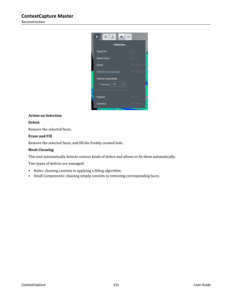
Action on Selection
Delete
Remove the selected faces.Erase and Fill
Remove the selected faces, and fill the freshly created hole.Mesh Cleaning
This tool automatically detects various kinds of defect and allows to fix them automatically.Two types of defects are managed:• Holes: cleaning consists in applying a filling algorithm.• Small Components: cleaning simply consists in removing corresponding faces.
ContextCapture MasterReconstruction
ContextCapture 151 User Guide

Figure 84: Mesh Cleaning panel
Mesh cleaning works in 3 steps:1. Detect: Select the type of targeted defects and click on Start detection.2. Filter: Filter the detected defects according to various criteria.3. Control and fix: browse and review detected defects, and choose to fix or ignore them.
Figure 85: Example of small component detected with mesh cleaning tool
ContextCapture MasterReconstruction
ContextCapture 152 User Guide

Touchup with a 3rd party software
Fix the current reference 3D model with retouches created with 3rd party software.To perform retouches, you must:1. Produce tiles for retouching.2. Apply tile corrections with some third-party software (Refer to Retouching).3. Import retouched tiles.
Figure 86: Import retouched tiles dialog
To import retouched tiles, click on Add retouched tiles directory in the selected retouch level section, and clickon Import retouched tiles to proceed.The following options are also proposed:• Spatial reference system: for georeferenced projects you can choose to import retouched tiles produced in a
custom spatial reference system.When importing retouched tiles, this option is automatically set if a metadata file is detected.Click on Edit Spatial reference system to select the appropriate reference system for your retouched dataset.
• Tag policy for modified tiles: a tag policy can be set to change tags of modified tiles.
ContextCapture MasterReconstruction
ContextCapture 153 User Guide

For retouched tiles to be successfully imported, their tile directory and filename must respect theContextCapture naming convention and must be the same as the ones of the production used for retouching.Example of valid retouched tile path:/Tile_xxx_yyy/ Tile_xxx_yyy.objSee also Retouching.
Reset
Clear a selection of the reference 3D model, so they are recomputed by later productions.
Note: Resetting all tiles and deleting all productions from the list allow you to re-edit all reconstruction settingsincluding Spatial framework and Processing settings.
Figure 87: Reset tiles dialog
To reset tiles, select the list of tiles to reset and click on Reset.See also Tile selection (on page 156).The following options are proposed:• Reset mode: reset can be applied on texture only or on both texture and geometry (default),• Tag policy for modified tiles: a tag policy can be set to change tags of modified tiles.
ContextCapture MasterReconstruction
ContextCapture 154 User Guide

Inter-tile color equalization
Apply inter-tile color equalization to limit color differences between tiles.
Note: This option is only available when the reconstruction has been done using the Standard color equalizationmode.ContextCapture generates the 3D model texture from various input photos that may have been acquired indifferent lighting conditions.In order to reduce radiometric differences between input photos in the 3D model texture, ContextCaptureautomatically proceeds to an advanced color equalization.However, in the case of tiled model reconstruction, ContextCapture performs color equalization independentlyon each tile. This implies that tiled reconstructions include color differences that need to be fixed.Once the reference 3D model with texture has been processed, an inter-tile color equalization can be computedto reduce radiometric differences between tiles.
Figure 88: The inter-tile color equalization dialog
New color equalizationCompute a new color equalization on available textured tiles.
ContextCapture MasterReconstruction
ContextCapture 155 User Guide

The inter-tile color equalization algorithm considers all processed tiles with texture and computes a globalequalization which will be used for later productions.Color equalization resets the reference 3D model texture. The changes will be applied to any new production.
Warning: textured tiles processed before version 3 will have to be recomputed to benefit from the new colorequalization feature. Reset the textures (Texture only mode) and perform a new production to upgrade them.See also Reset (on page 154).Note: Tiles with texture imported from retouched files (ie. tiles with retouching level Texture and Geometry) arenot taken into account in the color equalization computation.
Delete color equalizationRemove the existing color equalization and restore the initial color settings.
Deleting color equalization also resets the reference 3D model texture. A new production is needed to restorethe texture.
Building facade reconstruction, without (left) and with (right) inter-tile color equalization: color differencesbetween tiles are drastically reduced.
Tile selection
For a reconstruction using a tiling, tile selection may be needed for several operations in the workflow: to reset aset of tile, to produce a set of tiles, etc.
ContextCapture MasterReconstruction
ContextCapture 156 User Guide

Figure 89: The tile selection area
Check or uncheck tiles to define the selection.
Select all/Unselect all tiles/Invert selectionBasic management of the selection.
Add tagged tiles to selectionIf tags have been added to the reconstruction using the quality control interface, this command allows to usethem to select tiles. See also Quality control (on page 71).
Define selection from KML or DGNFor georeferenced reconstructions, the selection can be set from 2D polygons read from a KML or a DGN file. Anytile intersecting 2D polygons defined in the input file will be selected.
Select from 3D viewYou can select tiles interactively in a 3D view.
ContextCapture MasterReconstruction
ContextCapture 157 User Guide

Figure 90: Selection from 3D view dialog
Click on the model to select or deselect tiles. Use SHIFT or CTRL to perform multi-selection.Click on OK to validate the selection.For more information, see also Quality control (on page 71).
Load/save selectionTile selection may be loaded from / saved to a basic text format.Example of tile selection text file:Tile_+000_+001_+001Tile_+001_+002_+000Tile_+001_+001_+002
If needed, tile selection files can easily be created with a third-party tool.
ProductionA Production item manages the generation of a model, with error feedback, progress monitoring andnotifications about updates of the underlying reconstruction (example, retouching).
ContextCapture MasterProduction
ContextCapture 158 User Guide

Figure 91: Production item interface
Productions are defined in ContextCapture Master, but are processed by ContextCapture Engine.A production is defined by the following properties:• Output format and options,• Spatial reference system and extent,• Destination.Productions are used to process both the reconstruction reference model and to generate exported models invarious formats: 3D meshes, point clouds, orthophotos/DSM.Geometry constraints productions, available as Technology preview can automate geometry constraints creationon scene water surfaces to improve reconstruction.
Creating a new production
In the Reconstruction tab, click on Submit new production to create a new production.
NameEnter production name and description.PurposeSelect the purpose of the production to submit:
ContextCapture MasterProduction
ContextCapture 159 User Guide

• 3D mesh: Produce a 3D model optimized for visualization and analysis in third-party software.• 3D point cloud: Produce a colored point cloud for visualization and analysis in third-party software.• Orthophoto/DSM: Produce interoperable raster layers for visualization and analysis in third party GIS/CAD
software or image processing tools.• 3D mesh for retouching: Produce a 3D model which can be edited in a third-party software then imported
back into ContextCapture for later productions. An overlap between tiles is specially included. See also Retouching (on page 187).
• Reference 3D model only: Produce a 3D model which can be used only inside ContextCapture Master, forquality control and as cache for later productions. The reference 3D model is mandatory prior to process anyorthophoto/DSM productions.
• Annotations: Execute ContextInsights technology leveraging artificial intelligence to automatically extractinformation from your reality data. This information will be delivered under various possible formats: imageannotations, regular 3D-boxes, segmented meshes, point clouds or orthophotos.
Mesh and point cloud productions produce also the reference 3D model for internal use (reconstruction Reference model (on page 142)).Format and optionsChoose the output format and corresponding options.Proposed output formats and options depend on reconstruction properties and on the production purpose.For more details about proposed formats, see Output formats (on page 161).Spatial reference systemFor georeferenced reconstructions, choose the target coordinate system. See also Spatial reference system (onpage 192).Advanced options (according to format) : define the origin of the output coordinates in the production spatialreference system.For a 3D mesh, by default, the automatic origin is set close to the model in order to avoid very large 3D modelcoordinates, causing loss of accuracy in some third-party software.Height offsetSome formats allow to define a height offset. The height offset can be used to ease the integration of theproduction with existing data (ie. separate the produced 3D mesh from an existing terrain model).Please note that the height offset alters the production positioning.ExtentDefine the production extentFor 3D mesh or point cloud production, select the tiles you want to produce (enabled only for reconstructionwith several tiles).Several selection tools are proposed (KML import, etc.). See also Tile selection (on page 156).For Orthophoto/DSM, select the geographic extent to produce. A KML file can also be imported to define theextent.DestinationChoose the production location.According to the format, select the output directory (select an empty directory) or the base url where to createthe output production.
ContextCapture MasterProduction
ContextCapture 160 User Guide
Production processing
In the last page of the Production definition wizard, click on Submit to create the new production and submit thereconstruction job.
Create the new production and submit the reconstruction job.Once the production is submitted, the production item is created and manages monitoring of the reconstructionprocessing.
The reconstruction is processed on ContextCapture Engine side. If there is no engine currently listening tothe job queue, you must run an engine now or later to process the reconstructionNote: You can continue working with ContextCapture Master or even close the interface while the production ispending or running: the job will remain in the queue and computation will be performed on engine side.For more details about production monitoring, see General (on page 176).
Output formats
Proposed output formats and options depend on the reconstruction properties and on the production purpose.Note: On demand, Bentley Systems can develop exports to other 3D formats, for seamless integration with alarge majority of third-party 3D visualization and processing software.
3D meshProduce a 3D model optimized for visualization and analysis in third-party software.
Output formatsProposed 3D mesh formats are:
Note: Refer to Software Editions table to verify what output formats are the supported specifically by youredition.• 3MX format: an open format that we propose in order to facilitate the distribution of ContextCapture data. It
can be used for:• Web publishing, by using our free ContextCapture Web Viewer, you can publish or embed 3D models in
your web site.• Interoperability with other Bentley Systems products, such as ContextCapture Web Viewer and
MicroStation.• Interoperability with third-party applications (3D GIS).For more details about the 3MX format, see the format specifications in the ContextCapture installationdirectory.
ContextCapture MasterProduction
ContextCapture 161 User Guide

• Bentley Scalable Mesh (3SM): file format suitable for display, analysis and editing of large 3D meshes inBentley design applications.3SM 3D Tiles format can be directly displayed online in a 3D web viewer once published to ProjectWiseContextShare. See Share on ProjectWise ContextShare (on page 181).
• Smart3DCapture S3C (deprecated): Legacy format of ContextCapture , with compression, dynamic level-of-detail and paging.S3C format is optimized for local or online navigation of entire reconstructions in real time withContextCapture Viewer.S3C scenes can be edited with ContextCapture ContextCapture S3C Composer (on page 205).
• OBJ wavefront format: A portable 3D format that can be loaded by most CAD and 3D software.In this format, a single-level high resolution 3D mesh is proposed by default, but ContextCapture cangenerate level of detail if needed.OBJ productions can also be published to Sketchfab. See Publish to Sketchfab (on page 186).
• Bentley DGN: Native 3D format of MicroStation and other Bentley CAD application.• Collada DAE: Interchange file format for interactive 3D applications.• Autodesk FBX: 3D exchange format for Autodesk applications.• Stereolithography STL: Geometry format widely used for 3D printing (does not support texture).• ESRI i3s scene database: ESRI Indexed 3d Scene format for ArcGIS Scene Service.
This format is used to stream 3D GIS data to ESRI mobile, web and desktop clients. It's supported fromArcGIS Server version 10.3.1, ArcGIS Pro version 1.1 and ArcGIS SceneViewer version 3.7/10.3.1.It is recommended to produce with default options. Once the production is completed, Create a scene package(SLPK file) to get a single file easy to use with ESRI applications.
• Cesium 3D Tiles format, suitable for display in Cesium. More information on Cesium.• Google Earth KML: Hierarchical file format suited for real-time 3D display of very large datasets in Google
Earth.• OpenSceneGraph binary (OSGB): The native format of the open source OpenSceneGraph library, with
dynamic level-of-detail and paging.Best suited for SuperMap GIS.
• SuperMap S3M: Best suited for SuperMap GIS Software.• OpenCities Planner LodTree: Interoperability format for OpenCities Planner, based on XML files and 3D
models in Collada format.• LOD tree export: a level-of-detail tree exchange format, based on XML files and 3D models in Collada DAE
format.Best suited for Eternix Blaze Terra, Agency9 CityPlanner, Skyline TerraBuilder, DIGINEXT VirtualGeo.For more details about the LOD tree export format, see the format specifications in the ContextCaptureinstallation directory ( ).
• SpacEyes3D Builder layer: SpacEyes3D Builder layer file based on OSGB format.Best suited for SpacEyes3D Builder.A generic SpacEyes3D Builder GVW project file is also created.
Note: City-scale 3D models are split into tiles when using ContextCapture , and our level-of-detail (LOD)structure is generated for each tile independently. This leads to an incomplete level-of-detail structure and lowloading performance if the model contains a large number of tiles. As a solution to this problem, Bentley Systems
ContextCapture MasterProduction
ContextCapture 162 User Guide

has developed a post-processing tool capable of creating the entire LOD structure. This tool is accessible throughthe LOD option 'Quadtree across tiles'.
Options
Enabled options for 3D mesh depend on the chosen format:
• Include texture maps: include the texture or not (texture files and uv coordinates).• Color source:
• Visible colors: texture with photos with visible colors band.• Thermal: texture with photos with thermal band. Note: use 3D View or ContextCapture Viewer
Measurements tool to display temperature values on the resulting mesh.• Resolution: texture with a color scale showing resolution of input data (either photos or point clouds).
Note: use 3D View or ContextCapture Viewer Measurements tool to display resolution values on theresulting mesh.
• Texture compression: choose the JPEG quality level (50%, 75%, 90%, 100%).• Texture sharpening: enhance mesh texture by applying a sharp filter (enabled by default), this option can be
disabled to keep the initial image sharpness.• Level of detail (LOD): include levels of detail.
Type: type of LOD structure: simple levels, quadtree, octree, adaptive tree or Bing Maps Tiling System (onlyfor reconstruction based on Bing Maps SRS).Scope: Tile-wise (default) or Across tiles. See below.Node size: depending on the application, a larger number of lighter LOD nodes may be more advantageousthan a smaller number of heavier LOD nodes. This option allows to vary the size of LOD nodes, when using aquadtree, a octree or an adaptive tree.
• Skirt: the skirt is an additional border included around each geometry node and around each tile, to avoidcracks between the different parts of the mesh.The skirt is not tangent to the 3D model: it lies in the boundary of the 3D region of the node, and it is orientedtowards the interior of the 3D model. For example, the skirt between two side-by-side mesh nodes iscomposed of thin vertical strips. As the skirt length is given in pixels in input photos, it adapts to the localdataset resolution.
• Tile overlap: on reconstructions with tiling, an overlap between tiles is included to avoid cracks.The overlap is given in meters (or units for non-georeferenced blocks): the overlap is uniform over the 3Dmodel.
About the LOD Scope option 'Across tiles'The 3D models produced by ContextCapture are divided into tiles. In its current version, ContextCapture cangenerate a level-of-detail structure for each tile taken independently, but only the scope option 'Across tiles' willproduce global level-of- detail structure (e.g., a quadtree) for an entire reconstruction.Such a global LOD tree is desirable for real-time 3D rendering of a wide area without constraints on viewingaltitude or tilt angle. This requires the manipulation of very low resolution versions of large parts of the model,the extreme case being one small 3D mesh to represent the entire model at very low resolution.The LOD Scope option 'Across tiles' is based on the external command line tool "ExportUniqueMesh". See alsoExportUniqueMesh.
ContextCapture MasterProduction
ContextCapture 163 User Guide

A production with LOD Scope option 'Across tiles' is made in two steps:1. Production of reference 3D model.
This steps is managed as usual by ContextCapture Engines.2. LOD generation.
This step must be started manually once the first step is finished:• Either from the production interface with the command "Run LOD generation",
In this case, the LOD generation happens on this computer.Note: The LOD generation is not managed as usual jobs by ContextCapture Engine, but in a dedicatedcommand line tool running in a command prompt.
• Or with the command script 'generateLOD.bat' available in the production's output directory.In this case, the LOD generation can be started and processed from any computer, and even from severalcomputers in parallel (on computers equipped with ContextCapture Engine).
3D point cloudProduce a colored point cloud for visualization and analysis in third-party software.
Output formatsProposed 3D point cloud formats are:
• ASPRS LASer (LAS): public file format for interchange of 3-dimensional point cloud data.• Pointools POD file format: Point-cloud format for use within Bentley Pointools and any MicroStation-based
application.Note: When using tiling, point clouds productions generate one file per tile. You can use the command Mergepoint clouds (available once ContextCapture production is complete) to create one unique point cloud file.
Options• Point sampling: sampling distance option (LAS format only).
If provided in pixels, the sampling distance is defined in pixels in input photos: the sampling depends oninput photos resolution.if provided in meters (or units for non-georeferenced blocks), the sampling distance is defined in the 3Dcoordinate space: the sampling is uniform over the 3D model.
• Compression: LAZ (for LAS format only).If activated, produces zipped LAS with .laz file extension.
ContextCapture MasterProduction
ContextCapture 164 User Guide

Orthophoto/DSMProduce interoperable raster layers for visualization and analysis in third-party GIS/CAD software or imageprocessing tools.Note:
When using tiling, orthophoto/DSM productions generate one file per tile. You can use the command Mergeorthophoto parts (available once ContextCapture production is complete) to create a single merged file for theorthophoto and for the DSM.
DSM output formats• TIFF/GeoTIFF: standard raster format with georeferencing information.• ESRI ASCII raster/ASC: common ASCII format for grid exchange.• XYZ: basic ASCII format with 3 columns, each line containing the X, Y and Z coordinates.
The reference 3D model geometry must be available to process DSM.
Orthophoto output formats• TIFF/GeoTIFF: standard raster format with georeferencing information.• JPEG: standard compressed image format.• KML Super-overlay: hierarchical image file format suited for real-time 3D display of very large orthophotos
in Google Earth.
Options• Sampling distance: sampling distance option. Unit depends on the selected Spatial reference system.• Maximum image part dimension (px): define the maximum tile size for the resulting raster file.• Projection mode: define how the 2D data layer is processed from the 3D model (Highest point or Lowest
point).• Orthophoto/DSM: enable or disable the corresponding production.• Color source:
Optimized computation (visible colors): the best photos with visible colors band are selected according to theactual projection.Optimized computation (thermal): the best photos with thermal band are selected according to the actualprojection.Reference 3D model visible color: keep the internal reference 3D model with visible colors as is (mush faster).Reference 3D model (thermal): keep the internal reference 3D model with thermal band as is (mush faster).
• No data: pixel value or color representing no information. The reference 3D model texture and geometry must be available to process orthophoto.
Annotation DetectorsFirst thing to set is the annotation type. Then, unless for specific cases described hereafter, when a user importshis own source, annotations will result from a processing involving a detector. Detectors have been trained on
ContextCapture MasterProduction
ContextCapture 165 User Guide

specific data and will be optimized/limited to run on the same kind of data (same nature, same environment,same data quality and resolution). Below are the various types of detector you will be able to use for annotationprocessing:• Image - object detector• Image - segmentation detector• Pointcloud - segmentation detector• Orthophoto detector• Orthophoto + DSM detectorDetector types are designed to run on specific annotation types. Example, an orthophoto detector will not beapplicable in a 3D-segmentation job. A series of detector is available on dedicated Bentley Communitieswebpage.This page is accessible from ContextCapture Master Annotations page (Format/Options).
In case no detector is fitting your purpose, you are invited to submit a help request via your personal portal anddescribe your needs.
Annotation type2D Objects
This will detect objects in the images composing the block. Rectangular boxes will automatically be drawnaround objects of interest in your images. These rectangular boxes can be viewed in Photo view and arerecorded as a structured XML file in your production directory.
ContextCapture MasterProduction
ContextCapture 166 User Guide

Objects of interest are the ones your detector has been trained to recognize. The path to this detector must bedefined as below.
Only image-object detectors can be used to run this type of job.2D Segmentation
Each image of your dataset will be classified according the detector you use. Classes of interest will beautomatically extracted. It creates a PNG mask for each of your input images. Each pixel of this mask gets a class(unique pixel value) attributed. The series of masks is recorded in your production directory and linked to yourblock images by a single XML file. 2D Segmentation results can be reviewed in Photos tab. Classes of interest arethe ones defined during your detector's training.
ContextCapture MasterProduction
ContextCapture 167 User Guide

Only image-segmentation detectors can be used for this purpose.3D ObjectssIt delivers regular 3D-objects (boxes) around elements of interest. Elements of interest are the ones defined byyour detector or the 2D-annotations you chose to import. 3D objects are recorded in XML format and can beexported to DGN. Tie-points and point clouds (if available) can be used to better identify individual neighborinstances. The minimum number of views defines the amount of unique 2D-detection required so an annotationbecomes a 3D object.
3D Objects can be displayed in the 3D-view after processing and overlay an existing mesh-production.
ContextCapture MasterProduction
ContextCapture 168 User Guide

Only image-object detectors can be used for this purpose.3D Segmentation
This will execute a classification of 3D point cloud. Either the one usually processed by ContextCapture Engine(Reconstruction Reference Mesh) or the one that was imported in the block (Block Point Clouds). The raw resultfor this annotation job is a classified pointcloud. This classification is obtained after executing an appropriatedetector or after importing annotation in XML format. The resulting classified pointcloud can be exported in LASformat but cannot be displayed in ContextCapture Master 3DView. ContextCapture Editor can manage resultingclassified LAS file.
Out of 3D Segmentation, it is also possible to export individual 3D-objects. These 3D-objects are created basedon 3D-pointcloud classification: neighbor points of same class derive 1 individual object. 3D individual objects
ContextCapture MasterProduction
ContextCapture 169 User Guide

are recorded as XML (see 3D Objects) and can be exported as DGN or OBJ files. 3D Objects derived from 3DSegmentation can be displayed in ContextCapture Master 3D-View.
The part of the classified pointcloud composing a 3D-object can also be exported as individual LAS filesIndividual 3D-object identification can be improved by computing additional 2D-Objects detection or byimporting 2D-Object annotation. In such case, resulting annotation is still a classified point cloud, possibly joinedby individual 3D-objects that have been optimized using 2D-objects detection from images. Only image-segmentation and pointcloud-segmentation detectors can be used for this type of job. Image-object detector willalso be usable but limited to an assistance role to optimize neighbor objects separation.Segmented orthophotos
The result of this job is a series of orthophotos (and DSM if selected) paired with a series of PNG masks.Orthophotos are traditional ContextCapture orthophotos and production settings are described in dedicatedsection. PNG masks are the result of a classification driven by the user-defined detector. PNG masks are geo-registered and overlaying RGB-orthophotos. Each pixel of the PNG masks has unique value corresponding to aclass defined by the detector.
ContextCapture MasterProduction
ContextCapture 170 User Guide

Detector must be defined at job submission stage. Following classification of PNG masks, a vectorization ispossible as a Shapefile export. This transforms the class overlays in continuous polygon for optimized datamanagement in GIS software.
Only orthophoto and orthophoto+DSM detectors will be usable for this type of job. The role of DSM is tooptimize classification according to the height of the target elements. An example is building footprints: theirextraction will be more accurate if the detector has been trained and is submitted on an orthphoto+DSM caserather than a single orthophoto.Segmented orthophotos cannot be viewed in ContextCapture Master 3DView.Segmented mesh
The result from segmented mesh is a traditional ContextCapture mesh for which the texture is fused with lightcolor corresponding to detected elements. As a traditional mesh production, settings will be defined by the user:format, LOD, texture size, etc… and an additional setting will be defined for annotations.
Either a detector will be executed or an existing annotation will be imported as XML file to produce a mesh on-boarding class information in its texture. Minimum views to vote define the amount of detected occurrencesrequired to turn RGB-texture into classified texture.
ContextCapture MasterProduction
ContextCapture 171 User Guide

Segmented mesh can be viewed in ContextCapture Master 3DView (depending on the mesh format) as well as2DSegmentation result if any.Only image-segmentation and pointcloud-segmentation detectors can be used for this type of job.Mesh patches
Mesh patches will execute the same job as segmented mesh but will allow vectorization of all the areas of themesh's texture considered as classified. Each segmented texture patch will be exported as an OBJ file. Allmaterial contained within these OBJ files can be exported as a pointcloud.
Only image-segmentation and pointcloud segmentation detectors can be used for this type of job. Mesh patchescannot be viewed in ContextCapture Master 3DView
About LOD naming convention3D mesh productions with LOD use a specific naming convention for node files according to tile name, level ofdetail resolution, and node path (for LOD trees).For a node file "Tile_+000_+003_L20_000013.dae", the meaning is the following:
ContextCapture MasterProduction
ContextCapture 172 User Guide

• Tile_+000_+003: tile name.• L20: normalized level of detail which is related to ground resolution.
Table 1: Level of detail and ground resolution correspondence table (sample)
Level of detail Ground resolution (meter/pixel or unit/pixel)12 1613 814 415 216 117 0.518 0.2519 0.12520 0.0625
• 000013: optional node path, only included for LOD tree.Each digit of the node path corresponds to a child index (zero-based) in the tree. For quadtree and octreeproductions, the child index unambiguously indicates the quadrant/octant of the child node.
ContextCapture MasterProduction
ContextCapture 173 User Guide

Table 2: Example of node files for a production with LOD of type simple levels
ContextCapture MasterProduction
ContextCapture 174 User Guide

Table 3: Example of node files for a production with LOD of type quadtree
Extent
Defines the area of the production.The extent defines a clipping region for the production.By default, the production extent covers the whole region-of-interest of the reconstruction.The extent can be defined roughly by editing production bounds.An extruded polygon can be used to define the area more precisely from a DGN or from a KML file (if thereconstruction is georeferenced). Click on the button Import from polygon to specify the region of interest froma KML or a DGN file. The polygon file only defines a 2D polygon: top and bottom height can be defined from theinterface.For mesh productions using a tiling, you can limit the production to a subset of tiles. By default, ContextCapturewill select all the tiles necessary to cover the given extent.
Share
Most output formats can be published to ProjectWise ContextShare. See Publish to ProjectWise ContextShare.
Geometry constraints/Surface water detection (Technology preview)
ContextCapture MasterProduction
ContextCapture 175 User Guide

This technology preview involves advanced AI algorithms to automate detection of water surfaces which can beused as geometry constraints for reconstruction.The process requires photos, georeferenced positioning level, regular planar grid and AI compatible GPU.The process generates 3D meshes in OBJ format that can be used as geometry constraints for reconstruction.
Process on the cloud
Project processing can run on the cloud with ContextCapture cloud processing service.A ContextCapture Cloud Processing Console project is created from the block contents to allow cloud processingsubmission.Learn more about cloud ContextCapture cloud processing service (on page 180).
General
The production General tab manages the production processing.
Figure 92: Production General tab
DashboardThe dashboard allows to monitor production processing.
Restart processing of cancelled or failed jobs.
ContextCapture MasterProduction
ContextCapture 176 User Guide

Restart processing of jobs requiring update.
The existing output directory will be overwritten. When the reference 3D model is updated with retouched or reset tiles, existing productions are notified and
corresponding jobs are marked as requiring update.
Cancel processing or running or pending tiles.
Share the production on ProjectWise ContextShare. See Web publishing.
DetailsThe production is performed job by job, click on More details to get details about the production status of jobsand to monitor each job individually.Production processing can be controlled at job level from the job context menu.
Figure 93: Production job context menu
Troubleshooting
If the production of a job fails, our technical support team may ask you to export the log file of the job; you canexport it from the job context menu in the job table: choose Export log file for technical support.Note: The log file is only dedicated to our technical support team and is not human readable.
Production resultProduced job results appear in the selected output directory as soon as they are processed.Click on the link Open output directory to open the production folder in Windows Explorer.Note: For productions in 3MX format, you can display the output production with ContextCapture Viewer bydouble clicking the 3MX file.
ContextCapture MasterProduction
ContextCapture 177 User Guide

Figure 94: Example of production result displayed with ContextCapture Viewer
Properties
The Properties tab provides a summary of main production settings.
Figure 95: Production Properties tab
3D View
ContextCapture MasterProduction
ContextCapture 178 User Guide

The 3D view tab allows the user to visualize and control production output.
Job Queue MonitorThe Job queue monitor is an independent panel displaying the current status of the job queue.
Job queue monitor
Open the Job queue monitor panel.
Figure 96: The Job queue monitor panel
Job queue selection
If a Job queue different from the default one has been set for the active project, the monitor allows to shift from aJob queue to another: in the Job queue combo-box, select the Job queue you want to display.
Job queue status
The monitor displays a summary of the Job queue status:• Engine(s): displays the number of engines currently listening to the Job queue.• Pending job(s): displays the numbers of jobs which are waiting to be processed.• Running job(s): displays the number of jobs being currently processed by an engine.• Failed job(s): displays the number of jobs that have been rejected by an engine after an error.
Job queue management
Jobs are managed using database files in the job queue directory.The job queue cannot be managed directly, it can be done:
ContextCapture MasterJob Queue Monitor
ContextCapture 179 User Guide

• Per project from ContextCaptureMaster interface: aerotriangulation jobs and productions jobs can be simplymonitored from the user interface.
• From ContextCapture Master Kernel SDK: the SDK allows to monitor the job queue programmatically eitherper project, either globally with the dedicated Job Queue monitoring API.
Click on Open job queue directory to access the Job queue directory.
ContextCapture cloud processing serviceContextCapture can process aerotriangulation and 3D reconstruction jobs using ContextCapture Engine, but atany time processing can also run on the cloud using ContextCapture cloud processing service.From a block or from a reconstruction, simply click on the Submit button and choose Process on the cloud tocontinuerun processing withon ContextCapture cloud processing service.
Figure 97: Process on the cloud dialog
A ContextCapture Cloud Processing Console project is created from the project contents to allow cloudprocessing submission.
ContextCapture MasterContextCapture cloud processing service
ContextCapture 180 User Guide

Figure 98: ContextCapture Cloud Processing Console interface.
Please consult ContextCapture Cloud Processing Console user manual to learn more about cloud processing.
Web publishingContextCapture users have several options for publishing their original 3D content on the Internet.
Share on ProjectWise ContextShare
ProjectWise ContextShare is the Bentley platform to publish, manage and share reality data.From ContextCapture, you can directly share images, scans and orientations, or productions.Reality data can be shared and managed after being uploaded to ProjectWise ContextShare:1. From the block or from the production General tab, click on Share.
ContextCapture MasterWeb publishing
ContextCapture 181 User Guide

2. Associate a ProjectWise project if necessary not done yet.3. Click the Upload button to start uploading data.
4. Define publication name.5. Click on Upload.The upload time can significantly vary, depending on the size of the block and on your internet bandwidth.Typical upload time is about a few minutes.
Internet access is required for ProjectWise ContextShare uploads. You may have to define proxy settings ofyour internet connection. See Installation (on page 9), Licensing (on page 10), and Configuration (on page 9).Once reality data is uploaded, it is online and you can manage it from the CONNECT portal.To access published data, note that users must be signed-in under a Bentley CONNECT account with the rightpermissions.
ContextCapture MasterWeb publishing
ContextCapture 182 User Guide

Publish with ContextCapture Web Viewer
ContextCapture Web Viewer is made to publish or embed on a website the 3D models produced in 3MX formatwith ContextCapture .3MX productions can be visualized online in any web site using our free ContextCapture Web Viewer (on page202). Our web viewer is a cross-platform WebGL 3D viewer, suitable for desktops, tablets and smartphones. Itworks within any browser supporting webGL, without the use of plug-ins, and it can be embedded easily in anyweb page. You only need to upload your 3MX productions to your Web server (or to an online file storage webservice / content delivery network such as Azure Blob or Amazon S3/CloudFront) to publish or embed your 3Dmodels in your own web site.For web publishing your 3D model in 3MX format, the following method is the simplest:• Step 1: Produce your model in the 3MX format, with the WebGL ready option checked.• Step 2: Upload the entire Production folder (including both the Scene and App sub-folders) to your Web
server.• Step 3: Access the model by the address http://your_server/your_production/App/index.html.
Figure 99: Producing the 3MX format for web publishing.
Online file storage web services / content delivery networks such as Azure Blob/CDN or Amazon S3/CloudFrontare also supported.You can also customize your model visualization, by inserting your logo, for example, or by adding a modeldescription that viewers will be able to see.
ContextCapture MasterWeb publishing
ContextCapture 183 User Guide

The web visualization can be configured simply by editing the master 3MX file with a text editor.For more details, see Chapter 15, 3MX Web Deployment (on page 229).
Figure 100: Example of a 3MX production embedded in a web page with ContextCapture Web Viewer. Customizedscene settings are used to setup the logo and the description.
Note: City-scale 3D models are split into tiles when using ContextCapture , and the level-of-detail (LOD)structure used by the 3MX format is generated for each tile independently. This leads to an incomplete level-of-detail structure and low loading performance if the model contains a large number of tiles. As this is especiallyvisible in a web environment, BentleySystems has developed a post-processing tool capable of creating theentire LOD structure. This tool, called ExportUniqueMesh, is currently in its beta version. To find out more aboutExportUniqueMesh, please refer to the documentation included in your doc folder:
ContextCapture MasterWeb publishing
ContextCapture 184 User Guide

Publish to Cesium or ContextCapture Web Viewer 2.0
ContextCapture can generate 3D models with level-of-detail in the Cesium 3D Tiles format, for streaming anddisplay in Cesium web applications. Optionally, ContextCapture can generate a base Cesium or ContextCaptureWeb Viewer 2.0 application which can be published directly to the Web. Cesium is purely client-based, so theCesium 3D Tiles data and the Cesium application can be hosted on a static Web server.Online file storage web services/content delivery networks such as Azure Blobs/CDN or Amazon S3/CloudFrontare also supported.You can publish a 3D model to a Cesium or ContextCapture Web Viewer 2.0 application with the following steps:1. Produce your model in the Cesium 3D Tiles format, with the Generate base Cesium application (or
ContextCapture Web Viewer 2.0 application) option checked. For Cesium application, obtain a Bing Maps APIkey at https://www.bingmapsportal.com to be able to use Bing Maps as a source of imagery for the Cesiumglobe and enter the Bing Maps API key at the top of the app_cesium/main.js file of the production. ForContextCapture Web Viewer 2.0 application this step is not necessary.
2. Upload the entire Production folder (including both the Scene and App sub-folders) to your Web server.3. Access the Cesium app at the address http://your_server/your_production/App/index.html.Optionally, before steps 3 and 4, you can customize the base application.• For Cesium application, in a few lines of Javascript, you can add your credits/logo, mix the 3D model
generated by ContextCapture with other 3D models, raster or vector GIS data. Please refer to the Cesiumtutorials to get started.
• For ContextCapture Web Viewer 2.0 application, optionally before step 3, you can edit the configuration fileresources/config.json to change basic application settings:• unit: unit system for measurements, metric or imperial.• title: web page title.
ContextCapture MasterWeb publishing
ContextCapture 185 User Guide

Figure 101: Example of 3D model of Orlando published in Cesium 3D Tiles format to a Cesium Web application. Ittook about a hundred lines of JavaScript code to add vector and POI data to the Cesium base application generated
by ContextCapture .
Publish to Sketchfab
Sketchfab is a platform to publish, share and embed 3D models, you can sign up for free on sketchfab.com.To publish to Sketchfab, you must first produce your reconstruction in OBJ format.OBJ productions made of several tiles or with LOD are not supported.1. From the OBJ production General tab, click on Publish to Sketchfab.
Figure 102: OBJ production General tab.
ContextCapture MasterWeb publishing
ContextCapture 186 User Guide

2. Define your Sketchfab model properties, and your API token.You can find your API token in your Sketchfab registration confirmation email, or in your Sketchfab settings.
Figure 103: Publish to Sketchfab dialog3. Click on Publish to upload your model to Sketchfab.
The publishing time can significantly vary, depending on the size of the 3D model and on your internetbandwidth. The typical publishing time is of a few minutes.
Internet access is required for publishing to Sketchfab. You may have to define proxy settings of your internetconnection. See Installation (on page 10).Once your model is published, it is online and you can manage it from the Sketchfab website.Note: For a better result, we recommend to set the scene Shading to Shadeless from Sketchfab 3D settings.
RetouchingIn some cases, the output 3D models may include misconstructions that need to be fixed (unseen areas,reflective parts, water area...).Output 3D models may be fixed in a third party software at the end of, or during the ContextCapture process bymodifying the reconstruction reference 3D model.Retouching the ContextCapture reconstruction reference 3D model allows to benefit from ContextCaptureautomatic texturing and/or output formats.
ContextCapture MasterRetouching
ContextCapture 187 User Guide

Important notice: Retouching process may be avoided by managing Geometry constraints (on page 141).
Touch up workflow
In most cases, the advised process is the following:1. Identify the tiles where retouching is needed.
You must first produce the model in 3MX format and visualize it in ContextCapture Viewer. When defects aredetected, select the corresponding tiles (Menu > Tools > Tile selection) and export the list of tiles to retouch ina .TXT file.
2. Create production for retouching.Submit a new production with the purpose 3D model for retouching from the active reconstruction:• Name: as you want.• Description: optional.• Selection:
1. Manually select the desired tiles by checking the corresponding boxes.2. You can alternately load a tile selection file including the list of tiles with the Load selection button.3. Or you can automatically select tiles by loading a KML file with the Define selection from KML button.
All tiles included in / crossed by the polygon described in the KML will be selected.• Purpose: choose 3D mesh for retouching.• Format: DGN (default) or OBJ wavefront (default).• Options: include or not the texture (it is recommended to include texture as it helps interpretation during
retouching).Optional: change the color of non-textured faces.
• Directory: choose directory where files will be generated (see below).See also Production (on page 158).
You should preserve the file structure of the production to be able to later import retouched tiles intoContextCapture Master.
3. [Optional] Save a copy of the reference 3D model before retouching.If you want to keep track of all different stages of the retouching process, f or each tile, make a copy of thedirectory which contains the tile ready for retouching:• Keep this copy as the original tile automatically generated by ContextCapture .• Use the main version for saving the changes made to the tile during retouching. In case of multiple tiles,
this procedure can of course be applied to the parent directory containing all tiles.4. Edit tiles with a 3D application
Edit the tile with a third-party modeler like Bentley Descartes, Autodesk 3ds Max, Rhinoceros 3D, AutodeskMaya, Autodesk Mudbox , Autodesk MeshMixer , MeshLab ...
5. Import retouched tiles into ContextCapture MasterIn ContextCapture Master: at the reconstruction level, in the Reference 3D model tab, click on Importretouched tiles.Add the directory containing the modified tiles with the Add retouched tiles directory button in the tableGeometry touchup or Texture and geometry touchup, depending on the type of modification that wasperformed.
ContextCapture MasterRetouching
ContextCapture 188 User Guide

Click the Import retouched tiles button to close the dialog.See also Reference model (on page 142).It is recommended to check the imported tiles in ContextCapture Viewer: at the Reconstruction level, in theReference 3D model tab, right click on a tile and choose Open tile with ContextCapture Viewer.See also Reference model (on page 142).
6. Restart production Retouching a tile turns the entire productions that include it into the state requiring update.
You can update your production either by:• Updating the production(s) that include(s) the modified tiles: press the Submit update button at
production level to allow the modifications to be taken into account in a production.• Submit (ting) a new production that will take into account the modified tile(s).Note: In case you want to cancel modifications that were made to tiles outside ContextCapture Master, clickthe Reset tiles button at the reconstruction level in the Reference 3D model tab. It will open a dialog where youcan select the tiles that you want to reset and compute again. See also Reference model (on page 142).
ContextCapture MasterRetouching
ContextCapture 189 User Guide

Figure 104: Example of retouching on texture and geometry
Workflow diagram
Simple method without version managementThe smoothest process, but with no possibility to compare different versions.
ContextCapture MasterRetouching
ContextCapture 190 User Guide

With version managementMore elaborate, but allows to keep track of every version.
ContextCapture MasterRetouching
ContextCapture 191 User Guide

Spatial reference systemGeoreferenced projects will require to define a cartographic system by selecting a Spatial Reference System (SRS)at the reconstruction (Spatial framework) and production levels.The interface used for Spatial reference system choice proposes a default selection adapted to the context, a listof recent choices, and a direct access to the Spatial reference system database for more choice.
Figure 105: Spatial reference system choice
Spatial reference system database
In the spatial reference system list, click on More: Spatial reference system database to access the database.
ContextCapture MasterSpatial reference system
ContextCapture 192 User Guide

The database proposes more than 4000 spatial reference systems and is extensible with custom user definitions.Spatial reference systems are sorted by type:• Cartesian systems: 3D cartesian coordinate systems, including ECEF (geocentric) and Local East-North-Up
(ENU) coordinate system.• Geographic systems: coordinate systems based on a spheroid, for instance the WGS 84 latitude/longitude
coordinate system.• Projected systems: map projections sorted by projection type (UTM, Lambert Conformal Conic, etc.).
Projected systems also include the specific Web map projection Bing Maps system.• User defined systems: custom user definition.
Figure 106: Selection of a Spatial reference system from the database
ContextCapture MasterSpatial reference system
ContextCapture 193 User Guide

Use the filter to quickly find an existing Spatial reference system in the database and select an item in the filteredtable.For specific types of systems you may be asked to enter additional parameters:• Local East-North-Up (ENU): needs latitude and longitude of the origin. See also Useful concepts (on page 15).• Bing Maps system: needs level of detail from 1 to 23. See also http://msdn.microsoft.com.• User defined system: needs name and definition (see after).
Exporting Spatial reference systemProjected, geographic or user defined spatial reference systems can be exported in standard PRJ files includingthe WKT definition.Right-click on an item and choose Export to create a PRJ file.
Figure 107: Export of SRS definition
Exporting SRS allows to adjust a SRS definition externally or export a user defined SRS to another computer.
Vertical coordinate system
Geographic and projected systems use the datum on which they are based as height reference (ellipsoidalheight).For convenience you can override the vertical coordinate system to use another reference for heights.
Some vertical coordinate system definitions are based on geoid approximation subject to sampling andinterpolation, resulting in loss of vertical accuracy.Click on Override vertical coordinate system to select a new reference for heights.
ContextCapture MasterSpatial reference system
ContextCapture 194 User Guide

Figure 108: Overriding vertical coordinate system
Upon confirmation of your choice, a new user defined system is created with the overridden vertical coordinatesystem.Note: Ellipsoid height may be confusing compared to traditional mapping data using orthometric height or meansea level (MSL) as reference.Using EGM96 geoid as vertical coordinate system allows to get a good approximation of mean sea level (MSL)heights.
User defined system
Create custom spatial reference systems (on page 196)To find a spatial reference system, you can visit http://www.spatialreference.org/.PROJ.4
PROJ.4 declaration allows to enter a custom projection system (for instance "+proj=utm +zone=11+datum=WGS84").See also http://trac.osgeo.org/proj/wiki/GenParms.Well Known Text (WKT)
ContextCapture MasterSpatial reference system
ContextCapture 195 User Guide

OpenGIS Well Known Text format for coordinate systems can be provided in an attached PRJ file. In such case,enter the projection file path as SRS definition (for instance "C:\projections\myProjection.prj").Example of WKT definition contained in a PRJ (.prj) file:GEOGCS["WGS 84", DATUM["WGS_1984", SPHEROID["WGS 84",6378137,298.257223563, AUTHORITY["EPSG",7030]], TOWGS84[0,0,0,0,0,0,0], AUTHORITY["EPSG",6326]], PRIMEM["Greenwich",0,AUTHORITY["EPSG",8901]], UNIT["DMSH",0.0174532925199433,AUTHORITY["EPSG",9108]], AXIS["Lat",NORTH], AXIS["Long",EAST], AUTHORITY["EPSG",4326]]
Additional data
Some spatial reference systems use external dependencies which, prior to their use, must be installed in the"data\gdal" subdirectory of ContextCapture installation directory.For instance, a spatial reference system with a custom vertical coordinate system may use a GTX grid toapproximate the geoid.
Create custom spatial reference systemsYou can create custom spatial reference systems in three steps:1. Select the item Define new user system to start the creation of a new spatial reference system.
Figure 109: Starting the creation of a new user defined system2. Click on Edit to define the new spatial reference system.
ContextCapture MasterSpatial reference system
ContextCapture 196 User Guide

3. Enter a display name and the definition of the new user defined system.Any well known SRS definition can be entered, which includes PROJ.4 declarations, Well Known Text (WKT),or the name of a PRJ file containing a definition.
To find a spatial reference system, you can visit www.spatialreference.org.
ContextCapture MasterSpatial reference system
ContextCapture 197 User Guide

5ContextCapture Engine
ContextCapture Engine is the worker module of ContextCapture . It runs on a computer in the background,without user interaction. When it is not busy, the Engine takes a pending job in the queue, depending on itspriority and date of submission, and executes it. A job usually consists of an aerotriangulation or 3Dreconstruction process, using various computationally intensive algorithms (keypoint extraction, automatic tiepoint matching, bundle adjustment, dense image matching, robust 3D reconstruction, seamless texture mapping,texture atlas packing, level-of-detail generation, ...).ContextCapture Engine makes an extensive use of general-purpose computation on graphics processing units(GPGPU). Each Engine can exploit a single GPU.
Starting/ending the engineClick on the ContextCapture Engine desktop shortcut to start the engine.
Figure 110: ContextCapture Engine window
Once running, ContextCapture Engine listens to the Job queue directory which is configured thanks toContextCapture Settings (Refer to Installation (on page 10)).To close ContextCapture Engine, simply close the engine console. Any running Job will be moved back into thejob queue, with a pending status and its original priority. Pending jobs will remain in the Job queue , waiting tobe processed by a next execution of ContextCapture Engine.
ContextCapture 198 User Guide

ContextCapture Engine specializationBy default, ContextCapture Engine processes both aerotriangulation and reconstruction jobs.On a computer cluster, it may be useful to specialize engines to process only a specific type of job.To specialize ContextCapture Engine, run it with the following commands:• Aerotriangulation jobs only:
CCEngine --type AT• TileProduction and RasterProduction jobs only:
CCEngine --type "TileProductionRasterProduction"
Limiting the number of threadsSet the environment variable CC_MAX_THREADS to define the maximum number of parallel threads executingContextCapture Engine.This advanced setting may be useful to preserve responsiveness of other applications running on the samecomputer (e.g. leave one core for ContextCapture Master if it is installed on the same computer).
RestrictionsRemote Desktop Connection
ContextCapture Engine cannot work through a Microsoft Remote Desktop Connection because hardwareacceleration is disabled. However you can use VNC or a remote administration software like TeamViewer.Windows session
Switching Windows user while ContextCapture Engine is running will cause running computations to failbecause hardware acceleration is disabled when the user is not connected.
ContextCapture EngineContextCapture Engine specialization
ContextCapture 199 User Guide

6ContextCapture Viewer
ContextCapture Viewer is ContextCapture 's free lightweight visualization module. It is optimized forContextCapture 's 3MX format, which handle level-of-detail, paging and streaming, thus allowing visualization ofterabytes of 3D data, locally or online, with a smooth frame rate. You can use ContextCapture Viewer inconjunction with ContextCapture Master to control production quality all along the workflow. You can also use itto navigate final results.ContextCapture Viewer is integrated with ContextCapture , but it can also be installed separately as a stand-alonedesktop application. You can freely download the installer of its latest version from http://www.bentley.com/.ContextCapture Viewer is available for Windows 64-bit.
Figure 111: ContextCapture Viewer
ContextCapture 200 User Guide

ContextCapture Viewer can read the following 3D formats: 3MX, 3SM, S3C, A3D ( ContextCapture Master internalformat), OBJ, FBX, PLY, OSGB.Please consult the ContextCapture Viewer User Manual for more information.
Scene compositionContextCapture S3C Composer allows editing an existing S3C model to re-compose the 3D scene or add credits.ContextCapture S3C Composer (on page 205).
ContextCapture ViewerScene composition
ContextCapture 201 User Guide

7ContextCapture Web Viewer
The ContextCapture Web Viewer is the visualization software that allows users to view and navigateContextCapture 3MX models directly in a web browser.ContextCapture Web Viewer is a cross-platform WebGL 3D viewer, suitable for desktops, tablets andsmartphones. The Web Viewer can be embedded easily in any web page. It works within any browsersupporting webGL, without the use of plug-ins.3D models are loaded and displayed using level-of-detail (LOD), paging and streaming, and users can measuredistances and pick GPS coordinates.
ContextCapture 202 User Guide

Figure 112: Example of a 3MX production embedded in a web page with ContextCapture Web Viewer.
For more details, see Chapter 15, 3MX Web Deployment (on page 229).
ContextCapture Web Viewer
ContextCapture 203 User Guide

8Convert 3MX to Scalable Mesh
Menu Tools | Convert 3MX to Scalable MeshUse this tool to convert existing 3MX models to Scalable Mesh format (3SM).Limitation: The conversion does not support 3MX models including nodes with several texture maps. It mayhappen on 3MX models produced without LOD, on 3MX models produced with small maximum texture size, oron standard 3MX models in very rare cases.
For convenience, this tool is also available on any completed 3MX production.
ContextCapture 204 User Guide

9ContextCapture S3C Composer
ContextCapture S3C Composer is dedicated to the preparation of projects in S3C format for visualization inContextCapture Viewer.Warning: This tool is deprecated, to open it, launch bin/CC_S3CComposer.exe from ContextCapture ’s installationdirectory.ContextCapture S3C Composer allows editing of an existing S3C scene file produced by ContextCapture in orderto re-compose the 3D scene or add credits.
ContextCapture S3C Composer interface allows to:• Edit the list of models included in the scene,• Add title and logo,• Modify the reference coordinate system,
ContextCapture 205 User Guide

• Choose navigation and motion constraints,• Setup a S3C scene for web publishing,• Edit advanced options.
ContextCapture S3C Composer Main Interface
Figure 113: ContextCapture S3C Composer main interface
Models
Edit the list of models included in the scene.
An S3C scene is composed of tiles. You can add or remove tiles to/from the model.It is possible to add tiles coming from a different production if its coordinate system is compatible.External OBJ or FBX models can also be included in the scene.
Large OBJ or FBX files may slow down 3D navigation, because they do not feature level-of-detail.Use the preview function available in the context menu (right-click) to get a quick preview of a selection ofmodels in ContextCapture Viewer.
Information
Set the scene title and credits information.
Title
A title can be added and will appear at the top right corner of the ContextCapture Viewer interface.
ContextCapture S3C ComposerContextCapture S3C Composer Main Interface
ContextCapture 206 User Guide

Logo
A logo can be added, it will appear at the bottom right corner of the ContextCapture Viewer interface.PNG or JPG files are imported into a .a3d file (proprietary format) and copied next to the S3C scene file.Logo dimensions are limited to 300x300 pixels. Larger images are automatically reduced.
Coordinate system
Check georeferencing and coordinate system.
Model position
Displays the scene coordinate system.
Navigation
Choose navigation mode and motion constraints.
Minimum/Maximum height constraint
Enable a constraint on the height of the camera.Choose the height mode Relative to ground to set the height constraint relative to the ground.Maximum oblique viewing angle constraint
Enable a constraint on the angle between the vertical direction and the camera direction.Navigation mode
Select the default navigation mode.
The navigation mode of the scene can later be changed in ContextCapture Viewer.
Web publishing
Setup a S3C scene for a remote access to a Web server.
Web server
Base URL: Select the base URL on the Web server.
ContextCapture S3C ComposerContextCapture S3C Composer Main Interface
ContextCapture 207 User Guide

ContextCapture Viewer resolves relative paths of the different tiles specified in the S3C scene to a full URL, usingthis setting.Transfer settings
Maximum number of connections.
ContextCapture Viewer downloads the different nodes of the 3D scene using several simultaneous connections,in order to reduce latency. The number of simultaneous connections cannot exceed this setting.See also Web publishing (on page 29).
Advanced
Define advanced scene options.
Edit command line
Menu Tools > Edit command line
To allow scripting, the scene can also be composed through a command line.
Preview with ContextCapture Viewer
Menu Tools > Preview with ContextCapture Viewer
Preview the defined scene with ContextCapture Viewer.
Export instant loading scene fileMenu File > Export instant loading scene file
ContextCapture S3C ComposerExport instant loading scene file
ContextCapture 208 User Guide

Export instant loading scene file is available only in ContextCapture Center Edition. See Software Editions(on page 27).For very large datasets (with several hundred tiles), the default scene structure is not suited for efficient 3Dvisualization: loading and display performances may be affected, especially on the web.Exporting instant loading scene file allows to generate an instant loading scene format including additional dataand specific motion constraints which are suited for very large dataset visualization.The exported scene file integrates a symbolic representation of tiles which is used before their actual loading, aspecific LOD structure, and motion constraints on viewing angle and height.
Figure 114: 3D visualization of an instant loading scene file (at the beginning of loading).
This tool is suited only for scenes composed of a 2D tiling with a large number of tiles (typically >50).
ContextCapture S3C ComposerExport instant loading scene file
ContextCapture 209 User Guide

Figure 115: Exporting instant loading scene file
Output file
Enter the name of the new S3C scene file to create.The output file must be saved in the same directory as the input scene.Note: The output file is created with an associated A3D file which is also needed for the 3D visualization.Options
Skip lowest LOD
Define the lowest level-of-detail to use for the representation.Skipping lowest LODs allows to optimize loading time of relevant levels (and to avoid display of irrelevantsimplification levels that may affect perception of model quality).
ContextCapture S3C ComposerExport instant loading scene file
ContextCapture 210 User Guide

Warning: ignoring too many LODs may affect display performance.The starting LOD must be set according to the available level-of-details in scene tiles (eg. L16 corresponds to thefile "Tile_+000_+000_ L16 _00.a3d"). See also Output formats (on page 161)Disable this option to use the lowest level-of-detail available.Minimum height constraint
Motion constraint on the minimal height of the camera.A minimum height allows to forbid close-up views that may highlight insignificant details.Distance/angle constraints
Specific navigation constraints can be enabled to limit the allowed range of viewing distance and viewing angle,in order to avoid displaying too much data at a time, and hence to ensure optimal performance.Enter the minimum scene height to consider in the input model, and the maximum viewing distance to adjust themotion constraint, it also impacts the distance threshold for displaying a symbolic representation of tiles.
Known limitations: display policy and motion constraints of instant loading scene files are not suitedfor areas including large variations in relief.
ContextCapture S3C ComposerExport instant loading scene file
ContextCapture 211 User Guide

10ContextCapture Target Creator
ContextCapture Target Creator is a tool for creating printable targets based on QR codes or compact targets Chilitags and April tags. Targets can be automatically extracted from photos by ContextCapture to automate surveydata creation.Three types of surveys data can be created from target:• User Tie Point: : For QR Codes, user should specify a name and an optional description.• Control Points (QR Code only): it will be used for automatic rigid registration of the scene if at least 3 of these
targets are detected. User should specify a name for the control point. Predefined 3D coordinates with aspatial reference system can be attached for automatic geo-registration. Coordinates can also remain blankand be defined afterwards by the user in the input block using a control point with the exact same name.
• Constraint (QR code only): it will be used as automatic constraint. There are four types of constraints:• Origin: set the Origin (0,0,0) at the middle of the QR point.• Scale: set a distance between 2 QR points.• Axis: set X, Y or Z axis along the two QR codes.• Plane: set X, Y or Z axis along the two first QR codes, and orient the assigned axis along the third QR code.
Note that Axis and Plane constraints cannot be used in the same scene, and two similar constraints cannot beused in the same scene either. For more information, consult the Surveys: Positioning Constraints section.
ContextCapture 212 User Guide

ContextCapture Target Creator
ContextCapture 213 User Guide

11ContextCapture
ContextCapture MasterKernel SDK is a software development kit including a Python module, that allowsprogrammatic access to all the features of ContextCapture Master. This module acts in the place of the userinterface for full project creation, edition and monitoring.ContextCapture MasterKernel SDK is available only in ContextCapture Center Edition. For more information onthe editions please check Software Editions (on page 27).The ContextCapture MasterKernel Python module, CCMasterKernelPy, allows the development of customizedContextCapture applications in a simple manner thanks to Python scripts, like customized and/or automated 3Dreconstruction processes.The module API (Application Programming Interface) allows the control of all items used in a ContextCaptureMaster project (CCM file):• Project: creation, saving, edition, option settings, project tree management.• Block: import (Excel/XML), export (KML, XML, unwrapped photos), split, extract, photos/photogroup
creation and edition including camera properties and 3D position/rotation, control points creation andedition (3D positions and image measurements), user tie points creation and edition.
• AT (Aerotriangulation): components, positioning modes, settings, job submission and monitoring/control,export of the aerotriangulation report.
• Reconstruction: spatial framework (SRS, region of interest, tiling), reconstruction constraints, reference 3Dmodel (import/export retouches, color equalization), processing settings, export tiling to KML.
• Production: control of all parameters (purpose, format, options, extent and destination), jobs submission andmonitoring/control.
• Job queue monitoring.• Application settings: license checking, version control, software update checking on the internet.The API also includes various tools for data exchange (property tree, geometry), and geodesic computations.For more details about the SDK and the Python module API, please refer to ContextCapture SDK documentationin the ContextCapture installation directory.
ContextCapture 214 User Guide

12Job Monitoring
Project monitoring from ContextCapture MasterContextCapture Master includes monitoring features to manage jobs related to the active project.There are several types of jobs:• An Aerotriangulation job is created when submitting block aerotriangulation. Aerotriangulation job
monitoring is done from the General (on page 47).• TileProduction or RasterProduction jobs occur when submitting production. Production job monitoring is
done from the General (on page 176).The ContextCapture Master interface allows to submit, cancel, or resubmit jobs, only for jobs related to theactive project.ContextCapture Master also includes a Job Queue Monitor (on page 179) that allows to check job queue status.
Managing the job queueManaging the job queue allows to control all submitted jobs, from all projects and operators.
Managing the job queue, is only possible programmatically through ContextCapture MasterKernel SDK.See ContextCapture MasterKernel SDK documentation to learn more.Job priorities can be changed in contextual menu of AT Jobs or Production jobs and drive the priorities betweenjobs in a same job queue.AT jobs are set to "High" by default.
Reconstruction production are set to "Normal" by default.
ContextCapture 215 User Guide

Select "Urgent" or "High" if you need specific jobs to take advantage over others in the queue.Select "Pause" to pause the selected job, (note that the current task of the job will be finished first).
Job MonitoringManaging the job queue
ContextCapture 216 User Guide

13ContextCapture camera model
About this documentInformation in this document is subject to change without notice and is provided «as is» with no warranty.Bentley Systems makes no warranty of any kind with regards to this material, including, but not limited to, theimplied warranties of merchantability and fitness for a particular purpose. Bentley Systems shall not be liablefor errors contained herein or for any direct, indirect, special, incidental or consequential damages in connectionwith the use of this material.
Equations of the camera models
Perspective camera model
The world-to-image projection is given by:
where: is a 3D column vector representing the position of the scene point in the world spatial reference system, is a 2D column vector representing the position of the image point, in pixels. The origin is the center of the
upper-left image pixel, the x-axis is oriented to the right side of the image, and the y-axis is oriented to thebottom of the image.
is a 3D column vector representing the position of the camera center. is a 3 × 3 rotation matrix representing the rotation of the camera, which maps the axes of the world spatial
reference system to the camera axes defined by camera orientation. can specified either from:
Its coefficients:
ContextCapture 217 User Guide

Omega/Phi/Kappa angles:
Heading/Roll/Pitch angles:
Yaw/Pitch/Roll angles:
with:(Y, P, R) = (0, 0, 0) meaning that the camera is looking horizontally in the Y direction (X axis on the right, Z axisup).Yaw angle being the clockwise rotation around Z axis.Pitch angle being the counter clockwise rotation around X axis.Roll angle being the clockwise rotation around Y axis.
is a 3 × 3 rotation matrix bringing the camera axes defined by camera orientation to the canonical cameraaxes (x-axis oriented to the right side of the image, y-axis oriented to the bottom of the image, and z-axisoriented to the front of the camera):"XRightYDown":
"XLeftYDown":
"XLeftYUp":
"XRightYUp":
ContextCapture camera modelEquations of the camera models
ContextCapture 218 User Guide

"XDownYRight":
"XDownYLeft":
"XUpYLeft":
"XUpYRight":
is the perspective projection function defined by:
is the distortion function defined by:
(Please note that, in some other conventions, the roles of and are reversed).
is the focal matrix, where is the focal length of the camera in pixels, the skew parameterand the pixel ratio.
is a 2D column vector representing the position of the principal point of the camera, in pixels. The origin isthe center of the upper-left image pixel, the x-axis is oriented to the right side of the image, and the y-axis isoriented to the bottom of the image.
Fisheye camera model
The world-to-image projection is given by:
where:
ContextCapture camera modelEquations of the camera models
ContextCapture 219 User Guide

, , , and are defined as in the perspective camera model. is the fisheye projection and distortion function defined by:
•
• being distortion coefficients
•
is the fisheye focal matrix, set to when thesymmetric mode is chosen, being the focal length of the camera, in pixels.
ContextCapture camera modelEquations of the camera models
ContextCapture 220 User Guide

14ExportUniqueMesh: post-processing tool for
generating city-scale 3D models with completelevel-of-detail structure
Introduction
Summary
This document describes the motivation, the usage and the output format of ExportUniqueMesh, a post-processing tool developed by Bentley Systems to generate city-scale 3D models with complete level-of-detailstructure from a 3D reconstruction produced with ContextCapture standalone solution.Note: From ContextCapture update 5, ExportUniqueMesh access is made easier through the LOD type 'Quadtreeacross tiles' on mesh productions. See Production 3D mesh options.
About this document
Information in this document is subject to change without notice and is provided «as is» with no warranty.Bentley Systems makes no warranty of any kind with regards to this material, including, but not limited to, theimplied warranties of merchantability and fitness for a particular purpose. Bentley Systems shall not be liablefor errors contained herein or for any direct, indirect, special, incidental or consequential damages in connectionwith the use of this material.
MotivationThe 3D models produced by ContextCapture are divided into tiles. In its current version, ContextCapture cangenerate a level-of-detail structure for each tile taken independently, but is not able by default to generate aglobal level-of-detail structure (e.g., a quadtree) for an entire city.Such a global level of detail structure is desirable for real-time 3D rendering of an entire city without constraintson viewing altitude or tilt angle. This requires the manipulation of very low resolution versions of large parts ofthe city, the extreme case being one small 3D mesh to represent the entire city at very low resolution.
ContextCapture 221 User Guide

Bentley Systems has developed a post-processing tool called ExportUniqueMesh to fulfill this requirement. Thesame functionality is available through ContextCapture by submitting a production with "LOD Across Tiles" asthe LOD scope setting.
Usage
Example Usage
ExportUniqueMesh "D:/ ContextCapture /Stockholm_140604.txt" -o "D:/ ContextCapture /out" --cache "D:/ContextCapture /Cache" --scene "Stockholm" --format 3SM --lodType Adaptive --tileOverlap 1.5 --tilingSRS"EPSG:3011" --outputSRS "D:/ ContextCapture /SWEREF99 18 00 (EPSG_3011) + RH2000 height(EPSG_5613).prj" --textureSize 2048
Command-line syntax and allowed options
ExportUniqueMesh -i ... -o ... --tilingSRS ... --outputSRS ... [options]-i path of the input tile list (mandatory)-o path of the output directory. By default, use the
working directory--cache path of the cache directory. By default, use the "cache"
subdirectory of the working directory--scene output scene name. Default: "scene"--help, -h produce help message--tilingSRS definition of the tiling SRS, or path to its definition
(mandatory)--tileSize tile size, in the unit of the tiling SRS (mandatory)--heightRange height of the tiling in the tiling SRS, in "zmin zmax"
format (mandatory)--textureSize maximum texture size. Default value is 8192.
Minimum accepted value for the texture size is 1024.--textureQuality texture quality used for texture map compression
between 0 and 100. Default: 75--textureSharpening level of texture sharpening. Default: 100
ExportUniqueMesh: post-processing tool for generating city-scale 3D models withcomplete level-of-detail structureUsage
ContextCapture 222 User Guide

--textureColorSource color source used for texturing: Visible or Thermal.Default: Visible
--fill fill color for untextured facets, in RGB format (default:"128 128 128")
--tileOverlap size of the overlap added around each input tile(absolute unit value). Default: 0
--nodeOverlap size of the overlap added around the LOD nodes,relatively to the LOD scale
--skirtLength length of the skirts added at the boundary of LODnodes, relatively to the LOD scale (read more below).Default: 0 (no skirts)
--format output format. See below the list of possible values.Default is the 3MX format
--lodType type of LOD tree. Can be one of: Unary, Quadtree,Octree, Adaptive, BingMaps
--nodeSize relative size of level-of-detail nodes (read morebelow). Default: 1
--outputSRS definition of the output SRS, or path to its definition(mandatory)
--outputOrigin 3D position in the output SRS used as the origin ofmesh coordinates. By default, an automatic origin ischosen
--generateWebApp generate web application for formats supporting it(3MX and Cesium 3D Tiles)
--convertToWebReadyScalableMesh for 3SM format, convert the output to a Web-ReadyScalable Mesh
--omp Maximum number of CPU cores used for computation.Default: all CPU cores
Skirt: the skirt is an additional border included around each geometry node, to avoid cracks between thedifferent parts of the mesh. The skirt is not tangent to the 3D model: it lies in the boundary of the 3D region ofthe node, and it is oriented towards the interior of the 3D model. For example, the skirt between two side-by-side mesh nodes is composed of thin vertical strips. The skirt length depends of the resolution of each node.
ExportUniqueMesh: post-processing tool for generating city-scale 3D models withcomplete level-of-detail structureUsage
ContextCapture 223 User Guide

Documentation
Input tile list
The tile list must be in ASCII (UTF8 can cause problems). The tile list must contain paths to the tiles of thereference 3D model and extents of the corresponding tiles, in xmin ymin zmin xmax ymax zmax format, withcoordinates expressed in the tiling SRS..For example:l:\3381_Stockholm3D\Stockholm3D\Projectfiles\Block_19\Reconstruction_1\Productions\Production_22\Tile_+1349_+65882\438212 4602471 146438362.5 4602597.5 208The tile list can contain tiles from several reconstructions, provided the reconstructions have compatible tilings(same tiling SRS, tiles of the different reconstructions correctly partitioning space).No tile must be listed twice or more in the tile list.
Compatibility with older versions of ContextCapture
The --v2 parameter allows to process reference 3D models of ContextCapture version < 3.0.
Description of the source tiling structure
The structure of the level-of-detail tree is controlled by the extent of the input tiles and by the –lodType and --nodeSize parameters.The --nodeSize parameter controls the size of nodes. For a default value of 1, the leaf nodes cover about 400pixels of ground resolution, and every level-of-detail node covers about 400 times the resolution of the node.The depth of the level-of-detail tree is not uniform. It is adaptive to the resolution of the input tiles.The output SRS and origin must be specified and can be chosen independently of the settings of theContextCapture project.The fill color setting is similar to the "Color of untextured regions" setting of a reconstruction in ContextCaptureMaster.
Description of the output quadtree structure
The structure of the quadtree is controlled by the extent of the input tiles, by the --nodeSize parameter and bythe --resolution parameter.The --nodeSize parameter controls the size of nodes. For a default value of 1, the leaf nodes cover about 400pixels of ground resolution, and every level-of-detail node covers about 400 times the resolution of the node.The --resolution parameter sets the resolution of the leaf nodes, in meters. This resolution must be set to theresolution of the reference 3D model. In the current version of ExportUniqueMesh, the quadtree has a uniformdepth. In other words, it is assumed that all input tiles have the same resolution.
ExportUniqueMesh: post-processing tool for generating city-scale 3D models withcomplete level-of-detail structureUsage
ContextCapture 224 User Guide

The output SRS and origin must be specified and can be chosen independently of the settings of theContextCapture project.The fill color setting is similar to the "Color of untextured regions" setting of a reconstruction in ContextCaptureMaster.
Processing
The program does not use GPU computing. Any available computer with a powerful CPU can be used.Only one instance of the program should run on one computer, because one instance of the program uses all theprocessor cores of the computer.Thanks to the files written in the cache directory, the process can be resumed from its current progress if it isinterrupted by a computer failure, simply by running the program again with the same parameters. Inconsistentresults will be obtained if the program is run with different parameters after an interruption without clearingthe cache directory.The program can run on several computers in parallel. The same parameters (tile list, tiling structure, outputformat/options, etc) and the same - or an equivalent - output and cache directories must be given to the differentcomputers.Even if the program is run on several computers in parallel, only one computer writes the output files in the lastprocessing step: the first computer where the program was started. It is recommended to choose the computerwith more I/O performance for the output directory.Increasing the number of computers too much will lead to an I/O bottleneck. Using more than 10 computers tocreate a same 3D model is unlikely to be useful.
Licensing
The program requires activation by a ContextCapture license, allowing the Engine component.
OutputThe files created in the cache directory are for internal use only (resuming and parallelization capabilities). Theoutput 3D model database is created in the output directory.
Formats
The --format parameter can be chosen among the values below:• Formats natively supporting level-of-detail:
• "3SM" (Bentley Scalable Mesh and Web-Ready Scalable Mesh)• "3MX" (ContextCapture 3MX)• "Cesium 3D Tiles"• "ESRI i3s" (ESRI i3s scene database)• "Google Earth KML"• "SpacEyes3D" (SpacEyes3D Builder layer)
ExportUniqueMesh: post-processing tool for generating city-scale 3D models withcomplete level-of-detail structureOutput
ContextCapture 225 User Guide

• "OSGB" (OpenSceneGraph binary)• "LODTreeExport"• "S3C" (Smart3DCapture S3C)
• Formats only supporting single-resolution meshes:• "OBJ" (OBJ wavefront)• "FBX" (Autodesk FBX)• "Collada"• "STL" (StereoLithography)• "OpenFlight"• "Legacy" (Collada and XML files, read more below)
To know more about the different formats, please refer to the ContextCapture User Manual.For formats only supporting single-resolution meshes, the level-of-detail structure is materialized by the filestructure described below.
Level of Detail Structure
No matter the output format, the structure of the output database is the same. The nodes of the quadtree will benamed with a "key" text string indicating their level and their position in the tree in a very concise way.For example, for a quadtree, at each level,• 0 means the south-west child quadrant,• 1 the south-east child quadrant,• 2 the north-west child quadrant and• 3 the north-east child quadrant.For octrees and adaptive trees, there can be up to 8 children for each node of the level-of-detail tree.A directory level is added every three levels of the LOD tree to limit the number of files in a same directory.Hence, the names of the output files will be as follows ( .ext denotes the format-specific extension):root.extData/0.extData/1.extData/2.extData/3.extData/00.extData/01.ext...Data/000.ext...Data/000/0000.extData/000/0001.ext
ExportUniqueMesh: post-processing tool for generating city-scale 3D models withcomplete level-of-detail structureOutput
ContextCapture 226 User Guide

Data/000/0002.extData/000/0003.ext...Data/333/3333.ext...An example for a node at level 11 of the quadtree: Data/012/321/220/01232122023.extFor some formats, the nodes having a same parent node are stored in a single file. For example, Data/10t3.extcontains the four children of node 1.For some formats (for example, 3MX), the root node is saved in the Data subdirectory and the output directorycontains a format-specific scene file containing relevant metadata (e.g., SRS) and a reference to the root node.Warning: ExportUniqueMesh does not produce all nodes of the level-of-detail tree: it omits to save the emptynodes, if these nodes have an empty subtree.
Legacy format
This format is maintained only for compatibility with older versions of ExportUniqueMesh. We recommend touse other formats for your new work. Each node consists of three files:• a .dae file representing a 3D mesh in Collada format, with vertex and texture coordinates.Vertex coordinates of the 3D mesh are expressed in the output spatial reference system specified by the --outputSRS option, relatively to the origin given in the .xml metadata file described below.• a . jpg file containing the texture map of the Collada mesh.There is exactly one texture map for each 3D mesh. The size of the texture map can be different for differentnodes. The typical size of the texture map largely depends on the parameters of the output quadtree structure.• a .xml file, in XML format, containing some metadata of the 3D mesh.An example of this XML file is given below:
<Node> <Min> <x>152801.431926</x> <y>6578301.25849</y> <z>-3.76320197071</z> </Min> <Max> <x>154597.742193</x> <y>6580000.81617</y> <z>65.7186735891</z> </Max> <Origin> <x>153699.58706</x> <y>6579151.03733</y> <z>30.9777358092</z> </Origin> </Node>
ExportUniqueMesh: post-processing tool for generating city-scale 3D models withcomplete level-of-detail structureOutput
ContextCapture 227 User Guide

The Origin tag indicates the position in the output spatial reference system relatively to which 3D meshcoordinates are expressed.The Min and Max tags indicate the extent of the 3D mesh, in the output spatial reference system.Warning: the extent of the 3D mesh may exceed the theoretical extent of the node in the quadtree, because the3D mesh includes some small overlap and/or skirts to hide cracks in the 3D model between regions renderedwith different level-of-detail.
ExportUniqueMesh: post-processing tool for generating city-scale 3D models withcomplete level-of-detail structureOutput
ContextCapture 228 User Guide

153MX Web Deployment
How to produce for web viewingIf you wish to produce a scene for web viewing, you have to choose 3MX as the export format. You can do this inthe Production dialog of ContextCapture Master (see image below).
Figure 116: Choosing the web format at production time.
The web format
The 3MX format is the format dedicated to web publishing, but not only. The intended usage of 3MX is threefold:• Online distribution, by using our new ContextCapture Viewer.• Interoperability with other Bentley Systems products, such as MicroStation.• Interoperability with 3rd party applications (3D GIS).Since web publishing is not the only possible use of a 3MX production, certain options not suited for web aremade available at the production level. You should choose the most appropriate configuration for your purpose;see the next section for more details.
ContextCapture 229 User Guide
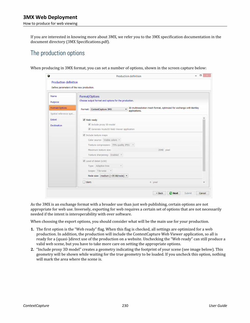
If you are interested in knowing more about 3MX, we refer you to the 3MX specification documentation in thedocument directory (3MX Specifications.pdf).
The production options
When producing in 3MX format, you can set a number of options, shown in the screen capture below:
As the 3MX is an exchange format with a broader use than just web publishing, certain options are notappropriate for web use. Inversely, exporting for web requires a certain set of options that are not necessarilyneeded if the intent is interoperability with over software.When choosing the export options, you should consider what will be the main use for your production.1. The first option is the “Web ready” flag. When this flag is checked, all settings are optimized for a web
production. In addition, the production will include the ContextCapture Web Viewer application, so all isready for a (quasi-)direct use of the production on a website. Unchecking the “Web ready” can still produce avalid web scene, but you have to take more care on setting the appropriate options.
2. “Include proxy 3D model” creates a geometry indicating the footprint of your scene (see image below). Thisgeometry will be shown while waiting for the true geometry to be loaded. If you uncheck this option, nothingwill mark the area where the scene is.
3MX Web DeploymentHow to produce for web viewing
ContextCapture 230 User Guide

3. The “Generate ContextCapture Web Viewer application” option produces the ContextCapture web applicationnext to the 3D scene in 3MX format. The application is used to display the scene in a browser, as described inthe “ How to deploy the production (on page 241)” section.
4. If “Include texture maps” is checked, the model textures will be generated, and a single texture will be at mostof the “maximum texture” size. If “Include texture maps” is unchecked, no texture will be generated for themodel. For web viewing, it is important that textures should not surpass 2048 pixels in size (either width orheight).
5. “Keep untextured regions” will generate geometry for areas that were reconstructed, but with no texturerecovered from the images. If unchecked, the untextured regions will be replaced by holes.
6. The “Level of detail” technology permits the decrease in the complexity of the scene as it moves away fromthe viewer. If this option is checked, simplified versions of the scene are generated alongside the most refinedreconstruction. Moreover, the geometry is split into parts that are faster to load. The node size indicates howbig a geometry part should be.
7. Lastly, the “Skirt” option adds an additional border around each geometry node and around each tile, to avoidcracks between the different parts of the mesh. The skirt is not tangent to the 3D model: it lies in theboundary of the 3D region of the node, and it is oriented towards the interior of the 3D model.
The production reference system
3MX Web DeploymentHow to produce for web viewing
ContextCapture 231 User Guide

For a georeferenced project, choosing the spatial reference system is important for the web application. Thespatial reference system impacts the 3D visualization and the coordinates’ management in the web application.You must select a spatial reference system with metric coordinates, appropriate for 3D visualization. Werecommend to use ENU systems, or standard UTM/WGS 84 projections.For coordinates’ management, the ContextCapture web application has its own, fairly limited, spatial referencesystem (SRS) database. The web viewer SRS database is limited to ENU systems and standard EPSG projections,and does not handle vertical datum. The Z value will be displayed as is in the web application, in the general caseusing the ellipsoid as reference.If you want the web application to display orthometric heights, you should produce the 3MX with a spatialreference system with a suited vertical datum (eg. EGM96).
The production result
When using the default settings, a 3MX production is a web-ready production. In this case, the production resultis split in 2 parts.First, the scene in 3MX format is in the Scene folder, as you can see in Figure 3. The scene is organized in a tree-like structure, very similar to the native S3C scene. The root of the scene is the Scene/YourProductionName.3mxfile. In Figure 3, the production is called WebGL, so the root 3MX file is Scene/WebGL.3mx. If you wish to knowmore about the 3MX organization, we refer you the 3MX specification documentation.
A second folder is included in a default 3MX production: the App folder. This contains the ContextCapture webapplication. Note that the App folder exists only if the option "Generate WebGL application" is checked atproduction time.The files you need to care about in the App folder are:• The index.html file. It is the root file for the application• The config.json file. This file points to the Scene/YourProductionName.3mx file, so the ContextCapture web
viewer knows what scene to load.
WarningIf you double click on index.html file, you will not see the application. Your preferred browser should open thefile and display a warning message like the one shown in the image below. This is due to browser securitysettings.
3MX Web DeploymentHow to produce for web viewing
ContextCapture 232 User Guide
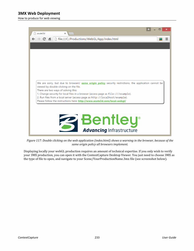
Figure 117: Double clicking on the web application (index.html) shows a warning in the browser, because of thesame origin policy all browsers implement.
Displaying locally your webGL production requires an amount of technical expertise. If you only wish to verifyyour 3MX production, you can open it with the ContextCapture Desktop Viewer. You just need to choose 3MX asthe type of file to open, and navigate to your Scene/YourProductionName.3mx file (see screenshot below).
3MX Web DeploymentHow to produce for web viewing
ContextCapture 233 User Guide

Figure 118: Opening a 3mx file in ContextCapture Desktop Viewer
If you do however need to open the ContextCapture Web Viewer locally, please see " Appendix A: View theContextCapture Web application locally (on page 253)" for step-by-step instructions.
How to configure the web application and sceneA default webGL production contains 2 different sets of data, each in a separate folder:• The produced scene, in 3MX format, is in the Scene folder• The webGL application, used to render the scene in a browser, is in the App folder.
3MX Web DeploymentHow to configure the web application and scene
ContextCapture 234 User Guide

Configuring the 3MX
There are 4 scene-specific pieces of data used by the web application, and that you should take care to define:• Your logo, which will be displayed by the 3D viewer.• A placeholder image that is shown by the web viewer whenever the 3D display is deactivated or there is an
error. This image should represent the 3MX scene.• The scene name and description, contained by the Scene/YourProduction.3mx and shown in the web viewer.• The default navigation modeAll 4 pieces of data are contained in the Scene folder.
Add your logo
Your logo will be displayed by the ContextCapture Web Viewer. To add it, you need to replace the image logo.pngcontained in the Scene folder with your own logo. You should preserve the name of the image, and use a small-sized logo, as the ContextCapture Web application does not resize your logo.
Add the scene image
The scene image is shown by the web viewer whenever the 3D display is deactivated or there is an error. Thisimage should represent the 3MX scene. To add it, you need to replace the image placeholder.jpg contained in theScene folder with your own logo. Note that you should preserve the name of the image.
Add the scene description
The scene name and description are shown in the ContextCapture Web viewer. The scene name and descriptioncan both be defined in the Scene/YourProduction.3mx file. You can open the file with a text editor, and replacethe name and description tag.For example, a production called “YourProduction” will have the default root YourProduction.3mx look like this:{"3mxVersion": 1,"name": " YourProduction","description": "Scene generated by ContextCapture, copyright <a href='http://www.bentley.com' target='_blank'>Bentley</a>",
3MX Web DeploymentHow to configure the web application and scene
ContextCapture 235 User Guide

"logo": "logo.png","sceneOptions": [{"navigationMode":"PAN"}],"layers": [{"type": "meshPyramid","id": "mesh0","name": "YourProduction","description": "Model generated by ContextCapture, copyright <a href='http://www.bentley.com' target='_blank'>Bentley</a>","SRS": "– given SRS –","SRSOrigin": [0,0,0],"root": "Data/YourProduction.3mxb"} ]}
To customize the message shown in the web viewer, you have to modify the name and description tags, shown inbold characters. The web application supports html tags in the scene description. For example, this tag:"description": "Scene generated by ContextCapture, ©<a href='http://www.bentley.com'target='_blank'>Bentley</a>",will be shown in the application like this:
3MX Web DeploymentHow to configure the web application and scene
ContextCapture 236 User Guide

Note: be careful with quotation marks. Because they signal the end of a tag, quotation marks should not be usedinside a scene description. For example, this code will produce an error:Error: "description": "Scene generated by ContextCapture, copyright <a href="http://www.bentley.com"target="_blank">Bentley</a>"If you do wish to use quotation marks in your description, please use either ' or \":OK: "description": "Scene generated by ContextCapture, copyright <a href=\"http://www.bentley.com\" target=\"_blank\">Bentley</a>"
Set the default navigation mode
The 4th setting you can define for a scene is the navigation mode. Just as the scene name and description, thenavigation mode is defined in the root 3MX: ../Scene/YourProduction.3mx file. You can open the file with a texteditor.To define the default navigation, you need to modify the tag sceneOptions. The line"sceneOptions": [{"navigationMode":"PAN"}]
sets the default navigation to PAN. The other option you can use is:“ORBIT”
Configuring the web viewer
The web viewer can be open in any browser − please see " How to deploy the production (on page 241)" for thenecessary settings. The browser should show something similar to the image below:
3MX Web DeploymentHow to configure the web application and scene
ContextCapture 237 User Guide

Figure 119: webGL viewer shown in a browser, by using a local server.
Address bar parameters
The first way of configuring the web viewer is through address bar parameters. The address bar is the placewhere we type the address for a chosen website, as indicated in the image above.3 options can be passed to the web viewer by using the address:• Add a play button to the screen. The application waits for the button to be pressed before showing the 3D
scene.• Set the 3D scene to be loaded• Camera viewpoint
Add a play button to the screenThe play button screen option is turned on by adding playBtn=on to the browser address. The application waitsfor the button to be pressed before showing the 3D scene. An example of how to do this is shown below:
3MX Web DeploymentHow to configure the web application and scene
ContextCapture 238 User Guide

The background image shown under the play button is the scene placeholder image. You can define this image asdescribed in "Configuring the 3MX".
Set the 3D scene to loadThe second option you can define in the address bar is the 3D scene to load. By default, the web viewer isattached to a webGL production and stores as scene to load the production scene. But you can change the sceneby giving the web viewer the web address of a 3mx file. In the example below, the Quarry scene is loaded fromthe local server by setting the option:scene=http://localhost/Quarry.3mx
3MX Web DeploymentHow to configure the web application and scene
ContextCapture 239 User Guide

Please note that the address parameter string is preceded by the character ? and the 2 options in the address areseparated by the character &.By exploiting the scene parameter, you can use the same copy of the web application with all your productions.We encourage you to do this for your deployment on the web.To make easier the access to various scenes, the list of available scenes can all be defined in the web viewerfolder, and accessed via aliases. This is done through to the 2nd method of parametrizing the web application —parameters given in the config.json file.
Set the camera viewpointIf you want to share with your clients a particular view of your 3D model, special camera parameters in theaddress bar allow you to do this.To obtain the current view's camera parameters, you can use the ContextCapture Web Viewer's Link option.Please go to the web viewer's interface section " Link to the model (on page 251)" to see more.
Configuration file parameters
The config.json file is found in the App folder, where App is the web application. The file can be used to definethe list of available scenes. A scene can then be accessed via an alias using the address bar scene parameter.
3MX Web DeploymentHow to configure the web application and scene
ContextCapture 240 User Guide

By default, the App folder is created during a webgl-ready production, and is stored next to the production’s 3Ddata. In this case, config.json contains the relative address of the 3D data, and will look something similar to this: { "URLs": [ { "alias":"YourProduction", "scene":"../Scene/YourProduction.3mx" } ] }
The configuration file is in JSON format. It indicates that there is a single 3MX scene the application can access,with the path to the root 3MX indicated by the “scene” tag. The alias is used to identify the scene by a name.To create the list of available scenes, you need to modify the file config.json, by adding the web address and analias for each scene. For example, the file below points to 2 scenes; the first scene is stored on the same server asthe web application, while the 2nd one is stored on CloudFront:{ "URLs": [ { "alias": "Quarry", "scene": "../DATA_3D/Quarry/Scene/Quarry.3mx" }, { "alias": "Marseille ", "scene": "http://deh9aqlpmcj1j6.cloudfront.net/Marseille/Scene/Marseille.3mx" } ]}
To switch between one scene or another in the web application, it is sufficient to give the alias as sceneparameter in the address bar. For example,• http://www.acute3d.com/s3c_resources/s3w-viewer/?scene=Quarry will show the Quarry scene above, and• http://www.acute3d.com/s3c_resources/s3w-viewer/?scene=Marseillewill show the Marseille scene stored
on CloudFront.If you modify the config.json, you should make sure your modifications can be read by the web application byvalidating the JSON format of the file. You can do this by copy-pasting the entire content of the file in a JSONvalidator, such as: http://jsonformatter.curiousconcept.com/
How to deploy the productionBoth local and remote 3MX productions can be seen in the ContextCapture Desktop Viewer. This sectiondescribes how to set up the web viewer and how to visualize your 3D scenes in a browser.
How to view locally
Due to browsers' same origin policy security restrictions, loading from a file system will fail with a securityexception, as in the screen capture below.
3MX Web DeploymentHow to deploy the production
ContextCapture 241 User Guide

Bypassing this warning and viewing the ContextCapture Web application locally requires an amount of technicalexpertise. We recommend you to use ContextCapture Desktop viewer to visualize your scenes locally, and to useyour web server for the ContextCaptureD Web application.However, if you do wish to view the ContextCapture Web application directly from your local disk, you can referto the “ Appendix A: View the ContextCapture Web application locally (on page 253)” instructions.
Deploy on the internet
There are 2 main options for you to deploy your productions on the internet:• Use your own server to host both the webGL application and your productions.• Use a cloud hosting service for your productions, and only use your own server for the webGL application.
Use your own server to host everything
In this case, the production folder can be used without change, if you took care to check the webGL exportoptions when producing your 3MX scene.It should be sufficient then to:
3MX Web DeploymentHow to deploy the production
ContextCapture 242 User Guide

• Copy the production folder on the server, at the appropriate location (next to your webpage index.html file,for example)
• Access the application by going to your_site/your_production_folder_path/App• If the page cannot be accessed, it might be necessary for you to change the access rights for
your_production_folderThe case described above is the simplest use-case, but it also results in the webGL application being copied everytime you create a new production.Alternatively, you can use the same webGL application for all your productions. It is sufficient to change itsconfiguration options, as described in the " Configuring the web viewer (on page 237)" section.In both cases, the setup should be very similar to your local server setup, if you chose to use one. It is sufficientto copy your data from the local to the remote server, in the same format.Just remember that the config.json file in your application has to contain relative, and not absolute paths. Inother words, scene paths like this: "../Scene/Production.3mx" will work for both the local and remote server. Butscene paths like this: "localhost/Scene/Production.3mx" will only work for the localhost.
Use cloud services for hosting your production
For large scenes, you might wish to host the productions on dedicated cloud servers, such as Azure Blob orAmazon S3. This is entirely possible, and your customers will still be able to access your demos using your siteaddress.To do this, you need to:• Load only the production scene onto a cloud server, making sure you enable cross-origin resource sharing for
the data.• Copy the webGL application on your own server, at the appropriate place.• Change the config.json file of the application to access the scene hosted on the cloud.• The demo will be accessible just as before, through your_site/your_application_folder address.We describe below how to publish the 3MX scene using Amazon S3.
Hosting on Amazon S3 (cloud front)
Create a dedicated bucket for webGL, because the bucket needs to have special read/access rights. Make surethat the bucket name is in lowercase if you want to deploy it to the CloudFront.• Go to bucket Permissions > Edit bucket settings and make the bucket public.
3MX Web DeploymentHow to deploy the production
ContextCapture 243 User Guide

• Change the Bucket policy, written in JSON, as follows (making sure the Resource has the correct Bucket ARN):{ "Version": "2012-10-17", "Statement": [ { "Sid": "AllowPublicRead", "Effect": "Allow", "Principal": { "AWS": "*" }, "Action": "s3:GetObject", "Resource": "YOUR_Bucket_ARN/*" } ]}
Any data in this bucket will be public. If the App folder was loaded together with the Scene, using the URLvisible when navigating to the App/index.html file should work:
The ContextCapture Web Viewer InterfaceThe ContextCapture Web Viewer is the visualization software that allows users to view and navigateContextCapture models directly on the web. 3D models are loaded and displayed using level-of-detail (LOD),paging and streaming, and users can measure distances and pick GPS coordinates.
Most of the viewer's options can be accessed by clicking on the Main menu .
Navigation
There are 2 types of 3D navigation in our web viewer: orbit and pan. You can switch between the 2 modes bygoing to Menu → Navigation mode (see screen capture below).
3MX Web DeploymentThe ContextCapture Web Viewer Interface
ContextCapture 244 User Guide

Orbit mode navigationMouse action Event
Left click + drag
Rotate
Right click + dragAlso works with CTRL + Left click + drag, or Mousewheel scroll
Zoom
Middle click + dragAlso works with SHIFT + Left click + drag
Pan
Double click
Bring the clicked point to the center of the screen
3MX Web DeploymentThe ContextCapture Web Viewer Interface
ContextCapture 245 User Guide

Touch action Event
One finger drag
Rotate and tilt
Two finger pinch
Zoom
Two finger drag, same direction
Pan
Two finger rotate
Rotate left and right
Double tap
Bring the tapped point to the center of the screen
Pan mode navigationMouse action Event
Left click + drag
Rotate
Right click + dragAlso works with CTRL + Left click + drag, or Mousewheel scroll
Zoom
3MX Web DeploymentThe ContextCapture Web Viewer Interface
ContextCapture 246 User Guide

Mouse action Event
Middle click + dragAlso works with SHIFT + Left click + drag
Pan
Double click
Bring the clicked point to the center of the screen
Touch action Event
One finger drag
Rotate and tilt
Two finger pinch
Zoom
Two finger drag, same direction
Pan
Two finger rotate
Rotate left and right
Double tap
Bring the tapped point to the center of the screen
Rendering
Rendering options can be accessed by going to Menu → Rendering mode (see screen capture below). Thewireframe mode can be turned on and off using these options.
3MX Web DeploymentThe ContextCapture Web Viewer Interface
ContextCapture 247 User Guide

Measurements and GIS positioning
To measure distances and determine point positions, open the Measurements window by using the Menu →Measurements option.
3MX Web DeploymentThe ContextCapture Web Viewer Interface
ContextCapture 248 User Guide

If the model is georeferenced, then GPS coordinates are shown in the selected spatial reference system, as wellas altitude, and distances are indicated in meters; otherwise distances and positions will be relative to thespatial reference system of the 3D model.
3MX Web DeploymentThe ContextCapture Web Viewer Interface
ContextCapture 249 User Guide

You can change the spatial reference system by clicking on the Measurements window options, and by choosing“Reference System …” (see screenshot below).
3MX Web DeploymentThe ContextCapture Web Viewer Interface
ContextCapture 250 User Guide

Link to the model
If you want to share with your clients a particular view of your 3D model, you can do this in the ContextCaptureWeb Viewer by going to Menu → Link. This will open up a window with 2 links: one for sharing, and one forembedding.The share link contains the current viewpoint for your scene, so you can send the 3D model in your chosenposition to your clients and partners.If you wish to include the 3D model inside your webpage, you only need to copy the embed code and paste it intothe source code of your website or blog.
3MX Web DeploymentThe ContextCapture Web Viewer Interface
ContextCapture 251 User Guide
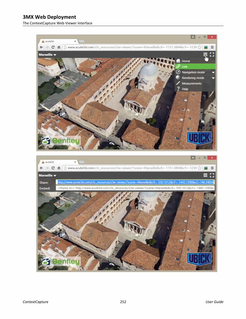
3MX Web DeploymentThe ContextCapture Web Viewer Interface
ContextCapture 252 User Guide

More information
You can find extra information about the navigation in the Help window, accessed via Menu → Help.The information about the 3D scene is found by clicking on the model title, in the upper left corner.
Appendix A: View the ContextCapture Web application locallyDue to browsers' same origin policy security restrictions, loading from a file system will fail with a securityexception, as in the screen capture below.
3MX Web DeploymentAppendix A: View the ContextCapture Web application locally
ContextCapture 253 User Guide

There are two ways of solving this:• Change security for local files in a browser (access page as file:///example)• Run files from a local server (access page as http://localhost/example)If you use option 1, be aware that you may open yourself to some vulnerabilities if using the same browser for aregular web surfing. You may want to create a separate browser profile / shortcut used just for localdevelopment to be safe. Because of these security issues, we strongly recommend you to use option 2.If you plan on regularly producing scenes for web viewing, using option 2 will not only be the secure way ofvisualizing the data, but it will also be less time consuming. The local server setup only needs to be done once,and then it will be ready for use every time you wish to view a new production.
Change local files security policy
Firefox:• Go to about:config (type the address in the Firefox navigation bar)• Find security.fileuri.strict_origin_policy parameter• Set it to false
3MX Web DeploymentAppendix A: View the ContextCapture Web application locally
ContextCapture 254 User Guide

Chrome:• Close all running Chrome instances first. The important word here is ‘all’. On Windows, you may check for
Chrome instances using the Windows Task Manager. Alternatively, if you see a Chrome icon in the systemtray, then you may open its context menu and click ‘Exit’. This should close all Chrome instances.
• Start a command prompt / terminal. On Windows, type Command Prompt in the Search box, and then, in thelist of results, double-click Command Prompt.
• Find the Chrome executable folder. On Windows, search for the file chrome.exe in a Navigator windows.• In the command prompt terminal, start the Chrome executable with a command line flag: path_to_chrome/
chrome --allow-file-access-from-files
Internet ExplorerTheoretically, Internet Explorer allows changes in the local files security policy. However, in our tests theoptions had no effect under Windows 8.0.
Safari• Enable the develop menu using the preferences panel, under Advanced → "Show develop menu in menu bar".• Then from the Safari "Develop" menu, select "Disable local file restrictions".• If you are editing & debugging using Safari, it is advisable to also select the "Disable caches" option in the
same menu.
Run local server
There are several options to choose from when installing a local server, for example Apache, Wamp, or nginx. Weare only going to suggest one, which has the advantage of being a zero-configuration server: http-server.
Installation• Install Node.js by using one of the installers from https://nodejs.org/.• Start a command prompt / terminal. On Windows, type Command Prompt in the Search box, and then, in the
list of results, double-click Command Prompt.• Make sure the last version of npm is installed by running this command in the terminal: sudo npm install
npm –g. In Windows, you can drop the sudo keyword, but you should run the command prompt asadministrator.
• Run in command prompt / terminal: npm install http-server –g• Create a folder where you wish to store all your server data, including the 3MX data.
Use• Place your 3MX data and your web viewer copy inside your server folder (the folder you created in the
Installation phase)• Start a command prompt / terminal. On Windows, type Command Prompt in the Search box, and then, in the
list of results, double-click Command Prompt• In the terminal, go to your server folder• Type http-server
3MX Web DeploymentAppendix A: View the ContextCapture Web application locally
ContextCapture 255 User Guide

• You can now access the server in any browser by typing http://localhost:8080. Navigate to the web viewerfolder to visualize your productions. You can check the “ Configuring the web viewer (on page 237)” sectionto see how to use the same web viewer for all your scenes.
3MX Web DeploymentAppendix A: View the ContextCapture Web application locally
ContextCapture 256 User Guide

163D multiresolution Mesh eXchange format (3MX)
3D multiresolution Mesh eXchange format (3MX) IntroductionThis document specifies the 3D multiresolution Mesh eXchange format (3MX). In designing 3MX, the goal was tocreate a lightweight open format that facilitates the distribution of our ContextCapture data, both online andtoward 3rd party applications.The intended usage of 3MX is:• Online distribution, by using our new WebGL viewer.• Interoperability with other Bentley Systems products, such as MicroStation.• Interoperability with 3rd party applications (3D GIS).3MX relies on a multi-resolution approach to achieve fast retrieval of very large 3D mesh data. Together with themesh compression used by the format, this makes data streaming possible for 3D rendering. Presently, bothContextCapture native viewer and our new WebGL viewer are able to read 3MX, locally or from a server.The 3MX format was conceived with extensibility in mind. ContextCapture currently produces 3MX data using asingle mesh compression type (OpenCTM), and a unique type of texture (JPG). However, the 3MX specificationputs no limits on the representation types for either meshes or images.All this said, the main characteristics of 3MX are:• Web friendly: easy to load in browsers• Compactness• Optimized for streaming: fast display possible.• Extensible• Multi-resolution representation: for handling very heavy data.The multi-resolution approach used in 3MX relies on a set of principles, described in the next section.
Level of detail principlesThe Level of detail (LOD) format allows the loading and visualization of very large 3D models. It does so by:• Decreasing the complexity of the representation as it moves away from the viewer.• Only loading the parts of the model that are visible from the current point of view.The LOD uses a tree structure, where the topmost node is a very coarse geometry, and the children are of aprogressively finer geometry. The leaf nodes are the finest granularity of the 3D representation.
ContextCapture 257 User Guide

Below is an example of a LOD tree, where each node contains geometry and texture. Different from a point cloudLOD representation, the child contains a full mesh specification that completely replaces the parent mesh.
The Level 2 node, for example, is split into 2 children, each containing half of the model, but at a finer scale thanthe parent. When showing Level 3 nodes, Level 2 should be hidden.The nodes are shown according to their proximity to the screen. Reverting to our example, when we are faraway from the screen, node A (Level 1) is shown. As we get closer and closer, the nodes are replaced by theirchildren. Node B will replace node A, for example, and nodes C and D will replace node B. If we zoom on the nodeC, it might be that node C will be replaced by level 4 nodes E and F, while its sibling, node D, remains unchanged.In the process of replacing nodes by their children, it might be the case that the node needs to disappear, withoutany geometry replacing it. Or mesh simplification can reduce so much a node geometry that the parent holds notriangle. Both situations require an empty node. Empty nodes are sometimes possible in our LOD representation,and they should be considered.At any given time, only one node from a possible tree path is shown. In our LOD example, if the node B is shown,then the Level 1 node is not shown, and neither are any of node B’s descendants.The question now is, when is a certain node “close enough” to be shown on the screen? For this, theContextCapture (Viewer or Web Viewer) approach is to consider how big the node appears on the screen (inpixels). To speed up calculations, the node’s bounding sphere is used as a proxy. The projection of the boundingsphere on the screen is a circle of diameter d. The diameter d is used as the measure of how big the node is onthe screen.Each node has attached a pixel maximum screen diameter. This value represents the maximum value of theprojected bounding sphere diameter d for which the node should be visible. Once this value is surpassed, thenode should be replaced by its children.
3D multiresolution Mesh eXchange format (3MX)Level of detail principles
ContextCapture 258 User Guide

In the example above, node A is shown for as long as its bounding sphere is projected onto the screen as a circleof a diameter less than 40 pixels. When the bounding sphere projection becomes too large, node B is loaded andshown.As we get closer to the model, we advance in the tree structure towards higher resolution nodes, but only forvisible areas! This means that only a small portion of the tree will be loaded in the memory at high resolution.In our example, nodes E and F become invisible when the camera zooms in on node D. So, while the D part of themodel is needed at a high resolution, nodes C, E and F are not useful anymore. To minimize memoryconsumption, they should be deleted.In general, a node is deleted when it has been invisible for a certain period of time. The nodes are not deletedimmediately after becoming invisible, because they have a high likelihood of becoming visible again when thecamera moves slightly. The delay in deleting the nodes ensures that the nodes are unlikely to be needed soon.Nodes are not deleted if any of the children are still needed.To resume, the principal ideas in LOD visualization of ContextCapture (Viewer or Web Viewer) data are:• Only one node from a path from root to leaf is seen at any given time.• A node is seen when its projection on the screen is within a predefined range (in pixels).• A node is loaded only when needed (when the parent is reaching the maximum projection area on screen).
3D multiresolution Mesh eXchange format (3MX)Level of detail principles
ContextCapture 259 User Guide

• Nodes that are unseen for a certain period of time are deleted.
3MX formatThe 3MX format consists of 2 types of file: one master file in JSON format and a tree of sub-folder/sub-files inbinary format. The single master file contains the scene metadata, and it is identified by the 3MX extension. Thebinary files contain the geometry, and are of type 3MXB (3MX binary). The 3MXB files typically describe oneunique 3D textured pyramidal mesh.Figure 3 shows an example of folder organization for a 3MX scene. The scene file is found in the root folder. Themesh description is split in multiple files, organized in a tree structure. Sub-folders represent subtrees of someintermediary node in the LOD structure described in the previous section.
Figure 120: Example of 3MX scene folder organization
3MX file
The 3MX contains general information about the scene, in JSON format. The JSON format was chosen because itis easy to handle and parse by web clients.A file in 3MX format holds:
3D multiresolution Mesh eXchange format (3MX)3MX format
ContextCapture 260 User Guide

• 3mxVersion – The file’s version number (float number)• name – The scene name (utf-8 string)• description – A description of the scene (utf-8 string).• It can contain HTML tags, but it should not contain new lines.• logo – Logo of the owner of the scene, as a relative path to an image (JPG or PNG).• sceneOptions – A collection of display options for the scene.• layers – One or several layers, containing different types of data. The geometry present in a scene is
described in such layers.The sceneOptions tag is reserved for the displaying application; custom fields can be added to define application-related options.In the layers collection, each layer has to have an ID and a type. Type-dependent data can be added to a layerdescription.Figure 4 shows a schema of the 3MX organization.
Figure 121: 3MX scene file format
For now, 3MX declares a single type of layer: meshPyramid. The meshPyramid layer describes a unique 3Dtextured pyramidal mesh, in the 3MXB form.
3D multiresolution Mesh eXchange format (3MX)3MX format
ContextCapture 261 User Guide

Figure 122: Mesh pyramid layer
A layer of type meshPyramid contains the following set of tags:id The layer's ID (utf-8 string).type: meshPyramid The layer type.name The layer name (utf-8 string).description A description of the layer (utf-8
string).SRS The spatial reference system (utf-8
string). Only needed forgeoreferenced data. See also AboutSpatial reference systems.
SRSOrigin: [O0, O1, O2] The model origin, in the specifiedSRS (array of float32). A point'scorrect coordinates in the specifiedSRS are P = Pmesh + SRSOrigin.Optional.
root The relative path to the root 3MXBfile (utf-8 string).
As an example, here is a full 3MX scene file:{"3mxVersion": 1,"name":"Marseille","description":"Marseille was generated using InterAtlas‘ oblique imagery system. ","logo":"interatlas_logo.png","sceneOptions":[{"navigation_mode":"PAN"}],"layers": [ {
3D multiresolution Mesh eXchange format (3MX)3MX format
ContextCapture 262 User Guide

"type":"meshPyramid","id":"mesh0","name":"Marseille","description":"This is a description of the model. It should be between quotation marks.","SRS": "EPSG:32631","SRSOrigin": [692625,4798280,0],"root": "Data/Marseille.3mxb" } ]}
Using the root contained in the scene layers, the geometry can be loaded, starting with the root 3MXB file.
3MXB file
3MXB geometry format respects the LOD principles described in the first section. It is organized as a treestructure, where children are a higher-resolution representation of the parent node.A 3MXB file is written in binary format. It packs or references all the data needed by a node or by a set of nodes,including all the textures and all the geometry. A single 3MXB file can represent several nodes in the LOD tree; inthis case, all the nodes are siblings, children of the same lower-resolution node.The 3MXB format has the following structure:
Figure 123: 3MBX file format
A 3MXB file starts with the magic number “3MXBO”. Following it is SH – the size of the file’s header in bytes; SHis a number in binary format (uint 32).The file header comes immediately after SH. The header is a string of size SH, in JSON format, made up of:version: 1
3D multiresolution Mesh eXchange format (3MX)3MX format
ContextCapture 263 User Guide

nodes: [node_data0, …., node_data m] array of sibling data, one for eachsibling.The content of the node datawill be specified in a dedicated section.
resources: [resource_data0, …., resource_data p]
array of resource metadata, one foreach resource (texture or geometry)needed by the nodes. The resourcedata is detailed further below.
The 3MXB file finishes with a number of binary buffers:Buffer0: a binary data buffer. The buffer type and its other
properties are specified in the header's resources.Buffern: a binary data buffer.
Node data
The node data contained in the header holds all the metadata for a single node included in the file:
id: the id of the sibling. It is unique inthe file, but not unique over theentire tree structure.
bbMin: [min0, min 1, min2] the smallest corner point of thebounding box. The bounding box isthe axis-aligned minimumbounding box of the node'sgeometry.
bbMax: [max0, max 1, max2] the largest corner point of thebounding box. The bounding box isthe axis-aligned minimumbounding box of the node'sgeometry.
maxScreenDiameter: dmax the maximum diameter, in pixels,for which this node should bevisible. Once passed this size onscreen, the node should be replacedby its children, if it has any.
3D multiresolution Mesh eXchange format (3MX)3MX format
ContextCapture 264 User Guide

children: [file_name0, …. ,file_namep] list of files (relative path) thatcontain the node's children.
resources: [geometry_ID0, …. ,geometry_IDr] list of the geometries forming thenode. The ID points to a resource inthe header's resources collection.
Note that the node’s resources array can be empty, defining in effect an empty node. Empty nodes are sometimespossible in the 3MX format, and they should be considered. They indicate that the parent geometry has to bemade invisible, without it being replaced by another geometry. The absence of children indicates, on thecontrary, that the node remains visible always, even if its screen projection surpasses its maxScreenDiameterparameter.
Resource dataThe header's resources collection describes all the resources needed to complete the definition of the entire setof nodes contained by the 3MXB file. For each resource, the data is organized as follows:
The resource ID is used to link nodes and resources together. For example, the ID is used to attach the geometryto the correct node, and to link the geometry to the corresponding texture.Four types of resources are possible:• textureBuffer, where the texture is included in the 3MXB file.• geometryBuffer, that describes a mesh as a binary buffer in the 3MXB file.• textureFile, where the texture is an external file.• geometryFile, where the mesh is an external file.For the buffer types, the binary data is included after the header, in one of the buffer objects. The buffers appearin the same relative order in the resource collection and in the buffer collection.1. textureBuffer
The texture buffer JSON data is organized as follows:{ "type":"textureBuffer", "id": "tex0", "format": "jpg", "size":1513, }
3D multiresolution Mesh eXchange format (3MX)3MX format
ContextCapture 265 User Guide

The " id" identifies the texture in a unique way in the file, but the id is not unique over the entire treestructure.The "format" tag indicates the type of the texture image. The image in a texture buffer is saved as a binarybuffer in the 3MXB file. The size of the binary data is indicated by the "size" value.
2. geometryBufferThe geometry buffer metadata is:{ "type":"geometryBuffer", "id": "geometry1", "format": "ctm", "size":835, "bbMin": [-1243.69,-314.572,52.6138], "bbMax": [1243.69,314.572,52.6138], "texture": "tex0" }
The "id" identifies the geometry in a unique way in the file, but the id is not unique over the entire treestructure.The "texture"tag is optional, and it appears only if the geometry has a texture. In this case, the texture isidentified by its ID. In the example above, the geometry uses the "tex0" texture defined in the "Texturebuffer" section.The "bbMin" and "bbMax" values describe the geometry's bounding box, in the same way as in the node data.
3. textureFileThe texture file JSON description is very similar to the texture buffer, except that instead of the size of abuffer, it indicates the path to an external file containing the image.{"type":"textureFile", "format": "jpg","id": "tex1","file": "subfolder/SomeTexture.jpg", }
4. geometryFileLike the texture file, the geometry file JSON contains the "file" tag, which points to an external geometry file.{"type":"geometryFile", "format": "obj","id": "geometry1","file": "subfolder/SomeMesh.obj","texture": "tex1" }
References by ID
The 3MXB file includes several resources, all of which have to be matched together. As mentioned before, theresource ID is used to link nodes and resources together.The first correspondence is between the node and its geometry. The node data includes a resources array,enumerating the IDs of every geometry resource belonging to the node. The header's resource array lists all the
3D multiresolution Mesh eXchange format (3MX)3MX format
ContextCapture 266 User Guide

resources needed by at least one node in the file. By matching the node's resource IDs with the header resourceIDs, the node's geometry can be reconstructed.In the image below, Node 0 has Resource 0 and Resource 1 as geometries. While Resource 0 is of type geometryfile, Resource 1 is of type geometry buffer, and the mesh is packed in Buffer 0. Node 1 is defined by the Resource2 geometry, found in Buffer 1. The order of resource appearance in the header is preserved for the buffers, so theattribution of Buffer 1 to Resource 2 is done automatically.
Figure 124: Resource attribution in 3MXB. The green color represents binary data, and the blue nuances representstring data.
A geometry belongs to a single node, but a node can have zero, one or several geometry meshes. The reasons forthe node having more than one geometry are twofold. In the first place, a single node can have textured and un-textured data or data textured with several images. In this case it is convenient to separate the geometry inseveral buffers, each corresponding to a single texture. In the second place, certain systems impose a geometrybuffer of at most MAX_USHORT length. For instance, when produced for the WebGL viewer, the geometry is splitinto buffers no larger than MAX_USHORT (65,535). This can be adapted to the targeted viewer.The second correspondence is between the geometry mesh and the corresponding texture. The resource ID isagain used for the matching. A geometry mesh can have either a single texture or none at all. If a texture isneeded, the "texture" tag is present in the geometry description. The indicated texture ID should be the ID of oneof the texture resources listed in the header’s resource collection.A texture can be used in different nodes, and by several geometries. In our example above, Resource 0 andResource 2 both share the texture in Resource p.A header complete example, in JSON format:{ "version":1, "nodes":[ { "id":"node0", "bbMin":[28.7803, -12.6859, 17.3977], "bbMax":[30.7065, -2.68368, 28.2069],
3D multiresolution Mesh eXchange format (3MX)3MX format
ContextCapture 267 User Guide

"maxScreenDiameter":118.819, "children": [ "Tile_p000_p000_p001_L20_00.3mxb"], "resources":[ "geometry0"] } ], "resources":[ { "type":"textureBuffer", "format":"jpg", "id":"texture0", "size":1665 }, { "type":"geometryBuffer", "format":"ctm", "id":"geometry0", "texture":"texture0", "bbMin":[28.7803, -12.6859, 17.3977], "bbMax":[30.7065, -2.68368, 28.2069], "size":1233 } ]}
Current implementationCurrently, ContextCapture exports the 3MX format with a number of fixed parameters, resulting in a particularversion of the 3MX format.One particularity of the ContextCapture export is that all the children of a node are stored in a single 3MXB file.This is done to speed-up loading, and to reduce the used memory. If we revert to our example from the Level ofdetail principles section, the exported 3MX scene will look like this:
3D multiresolution Mesh eXchange format (3MX)Current implementation
ContextCapture 268 User Guide

where the square areas represent a 3MXB file.
3MX Export
The 3MX scene currently exported is limited to one unique 3D textured pyramidal mesh. This means that asingle layer is generated, of type meshPyramid. Other data, such as OBJ meshes or labels attached to the 3Dmesh, are not considered in the present implementation.Aside from the single layer, the exported 3MX file has a single scene option in the sceneOptions collection. Thisoption is navigationMode, and it can be either "ORBIT" or "PAN". This option can be used to initialize the way theuser interacts with the scene.
3MXB export
The exported 3MXB files each contain a siblinghood in the LOD tree, packed in a single binary file. The produced3MXB will therefore only have resources of type texture buffer and geometry buffer. Resources of type texturefile or geometry file are not being generated by ContextCapture.1. textureBuffer
Currently, only the jpg format is supported by the ContextCapture export. The jpg is packed inside a filebuffer, without modifications.
2. 2geometryBufferA geometry buffer is currently only an OpenCTM file (http://openctm.sourceforge.net/), saved as a binarybuffer in the 3MXB file.
3D multiresolution Mesh eXchange format (3MX)Current implementation
ContextCapture 269 User Guide

The OpenCTM format includes:positions [v0, … , vn] array of vertex positions. vi = [p0, p1, p2]normals [n0, … , nn] array of vertex normal.
Optional, and currently not included.texture coordinates: [uv0, … , uvn] array of vertex texture coordinates. uvi = [u, v].
Only valid when the geometry has an attachedtexture.
triangle indices: [i0, … , it] array of vertex indices, ix = an array position in thevertex array.The indices, takes by 3, form the triangles.
About Spatial Reference SystemThe spatial reference system is defined with a single definition string, which is commonly an EPSG definition, ora Well Known Text (WKT) string. Some specific custom definitions may also be used.EPSG codesMost EPSG definitions corresponding to standard projection cartographic systems are supported.The syntax is “EPSG:CODE” to define a cartographic system with its EPSG code (for instance “EPSG:32651”).Non metric systems are not used (eg. geographic systems).Well Known Text (WKT)OpenGIS Well Known Text format for coordinate systems can be provided in as is.Other definitionsThe following syntax may be used to define local East-North-Up (ENU) systems: “ENU:LAT,LON” (for instance“ENU:41.57231,2.26157”).
Pointclouds Technical SpecificationsPTX
General
ContextCapture supports PTX format from Leica Cyclone.All PTX point clouds are considered to have intensity information and so point clouds will always have theintensity attribute. Color information is detected if a point line has seven elements.Static
Header length and point list lengths must be reliable. A missing line in the header or a missing point betweentwo headers leads to a failed importation. However, a corrupted point line will be ignored.
3D multiresolution Mesh eXchange format (3MX)About Spatial Reference System
ContextCapture 270 User Guide

Point coordinates is computed using scanner registered position as scanner location and the transformationmatrix.If the scanner position is provided from the user interface, the transformation matrix in the PTX header is stillused to compute point coordinates. Autodetect position feature is not available for PTX.LAS
General
ContextCapture supports LAS format 1.0, 1.1 and 1.2.Color information is detected based on LAS Point data record format used. Point clouds will have a colorattribute if the point format used is 2 or 3. Intensity attribute is detected if at least one point doesn’t have anintensity set to 0.Static
LAS format doesn’t support scanner position information. When importing a static LAS, the user must provide ascanner location from the user interface or use the autodetect feature.Mobile
The point clouds and the trajectory data are linked using timestamps. Therefore, LAS point data record formatmust be 1 or 3.E57
General
ContextCapture support E57 format 1.0 and Leica E57 timebounds.Color information is detected based on the E57 file header. If in the header, the point fields of blue color, redcolor and green color are set to true, the pointcloud will have color attribute. For intensity, the point field ofintensity is used to set the intensity attribute.Static
The position of scanners is read from the pose information of each E57 scans. If this information is missing,ContextCapture assumes the pose is set to the identity. Georeferenced static scans must have a pose information,as an identity pose doesn’t make sense for georeferenced point clouds.If the scanner position is provided from the user interface or is autodetected, the pose information in the E57scans is still used to compute point coordinates.Mobile
The point clouds and the trajectory data are linked using timestamps. Therefore, at least one E57 scan must havea timestamp field. If the E57 scan as an acquisitionStart structure, the value is used as an offset for thetimestamp stored for each point. If the E57 has a timeBounds structure and a timeMinimum structure, thetimeMinimum value is used as an offset for the timestamp stored for each point, overriding the acquisitionStartstructure.Trajectory data
Trajectory information is required to import mobile scans. A trajectory file must contain a list of the scannerpositions associated with timestamps. The positions must be provided in the same spatial reference system thanthe point cloud coordinates, and trajectory timestamps must overlap with points timestamps.Trajectory example:Time;X;Y;Z189321.10;15.96;-52.12;133.68
3D multiresolution Mesh eXchange format (3MX)Pointclouds Technical Specifications
ContextCapture 271 User Guide

189321.20;15.21;-51.21;134.01189321.30;14.75;-50.37;134.35189321.40;14.10;-49.50;134.31189321.10;13.78;-48.69;134.43...
PLY
General
ContextCapture supports general PLY format and NavVis PLY format.In ContextCapture, PLY format is considered a mobile format. No trajectory data is needed, but a normalinformation is required for each point.Property names for normal must be nx, ny, nz. Property names for color must be red, green, blue.POD General
ContextCapture supports POD format, the Bentley pointcloud format. Currently it is only possible to import it forstatic scans with a unique source.Static
The user must specify the location of the scan for a specific POD file, or use the autodetect feature in order forthe import to be successful.
3D multiresolution Mesh eXchange format (3MX)Pointclouds Technical Specifications
ContextCapture 272 User Guide

Index
Numerics2D/3D GIS software 293D multiresolution Mesh
eXchange format 2573D view 723D Visualization 293MX Export 2693MX file 2603MX format 2603MX Web Deployment 2293MXB export 2693MXB file 263
AAbout paths with non-ASCII
characters 26About Remote desktop
connection 26About Spatial Reference System
270About this document 217, 221About Windows session 26Add the scene description 235Add the scene image 235Add your logo 235Adding Photos 48Adding the camera model of a
photogroup 133Adding user tie points 65Additional data 86, 87Address bar parameters
238–240aerotriangulation
Result display 96Aerotriangulation
Aerotriangulation report 97Aerotriangulation processing 95aerotriangulation result
Troubleshooting 99Aerotriangulation result 96
Appendix AView the ContextCapture
Web applicationlocally 253
Applications 99Apply a camera model from the
database 130Apply a camera model manually
to a photogroup 130Architecture 23ATExport XML format 128Automatic tie points checking
99Axis constraint 67
BBasemap manager 38Bing maps tile system 139–141Block 45BlocksExchange XML format
119
CCAD/3D software 28Camera database 129capturing 22Change local files security policy
254, 255Color equalization mode 146Command-line syntax and
allowed options 222Compatibility with older
versions ofContextCapture 224
Components 89Configuration 11Configuration file parameters
240Configuring the 3MX 235Configuring the web viewer 237
ContextCapture 21ContextCapture camera model
217ContextCapture Engine 198, 199ContextCapture Master 30ContextCapture MasterKernel
SDK 214ContextCapture S3C Composer
205ContextCapture Viewer 200,
201ContextCapture Web Viewer
202Control Point Properties 62–64Control points 59Control points checking 99Creating a new block by
aerotriangulation 88Creating a new production 159Current implementation 268
DDelete color equalization 156deploy on the internet 242Description of the output
quadtree structure 224Description of the source tiling
structure 224
EExample usage 222Export block 114Export instant loading scene file
208Export to XML 114ExportUniqueMesh 221Extract block 112, 113
ContextCapture 273 User Guide

FFields 107Fisheye camera model 219Formats 225
GGeneral Block tab 47, 48General Reconstruction Tab 136Geometric simplification 145
HHow to configure the web
application and scene234
How to deploy the production241
How to produce for webviewing 229
how to view locally 241
IImport blocks 108import photo positions
Data properties 104, 106,107
File format 103Input file 102
Import photo positions 102Import retouches 149Import video frames 100Importing control points 61Input data file formats 19Input tile list 224Installation 10Inter-tile color equalization 155interoperability 29Interoperability 28Introduction 257
JJob Monitoring 215Job Queue Monitor 179
LLegacy format 227Level of detail principles 257Licensing 12, 225Link to the model 251Load/unload blocks 117, 118
MManage the user camera
database 132, 133mapping 22Measurements and GIS
positioning 248Merge blocks 118More information 253Motivation 221MS Excel block definition 127
Nnatural environments 22Navigation 244–246New color equalization 155Node data 264
OOptions 34, 35Origin constraint 67Output 225output block name 88output formats
3D mesh 161, 1633D point cloud 164Orthophoto/DSM 165, 166,
172Output formats 161
PPerformance 26Perspective camera model 217Photo acquisition 17–19Photo properties 52Photogroups 49Photos 48Photos display options 69, 70
Plane constraint 68Point clouds 54Positioning Constraints 66Positioning data 20Positioning/georeferencing
90–92Preparing the Imagery Dataset
17Principle 21Processing 225processing settings
Low-level settings 149Processing settings
Hole-filling 145processing settings tab
Geometric precision 145Production 158Production General 176, 177Production processing 161Project 31Project General 32, 33Properties 178Publish to Cesium 185Publish to Sketchfab 186Publish with ContextCapture
Web Viewer 183
QQuadtree structure 226Quality control 71, 72
Rrange subjects 22Reconstruction 134Reconstruction constraints 141Reference 3D model 142, 143Reference manager 35–38References by ID 266Region of interest 138Rendering 247Reset 154Resolution Limit 149Resource data 265Retouching 187, 188, 190Run local server 255
ContextCapture 274 User Guide

SS3C Composer Main Interface
206–208Scale constraint 67Selection of matching pairs 144Set the default navigation mode
237Settings 92Software Editions 27spatial framework 137Spatial framework 137Spatial reference system 192Spatial reference system (SRS)
137Spatial reference system
database 192, 194Split block 109Split processing 111Split settings 110, 111
Summary 221System Requirements 25
TThe ContextCapture Web
Viewer Interface 244The production options 230The production reference
system 231The production result 232The web format 229Tie Points 64Tile selection 156–158Tiling 139–141
UUntextured regions
representation 148
urban environments 22Use cloud services for hosting
your production 243Use your own server to host
everything 242Useful concepts 15User defined system 195
VVertical coordinate system 194
WWeb publishing 29Welcome 7What's New? 7Workflow 25
ContextCapture 275 User Guide