
English Translation of Professor August Pieper's Paper "Quo propior Luthero, eo melior theologus"
Upload
khangminh22Category
view
1download
0
Page 1 of 30
Title: Structural Analysis of PXIE Cryostat
Calculation No.: NE-EO-2013-003 Revision Number: 0
CALCULATION COVER SHEET
Supersedes Calculation No.:
Total Number of Attachments:
Analyzed System:
PXIE HWR162
Purpose of Revision: Initial Issue
PREPARER
Richard L. Fischer
Print Name Signature Date
REVIEWER
Print Name Signature Date
VENDOR APPROVER (if vendor-supplied calculation)
n.a.
Print Name Signature Date
FINAL APPROVER
Print Name Signature Date
Page 2 of 30
Title: Structural Analysis of PXIE Cryostat
Calculation No.: NE-EO-2013-003 Revision Number: 0
TABLE OF CONTENTS
COVER SHEET 1
TABLE OF CONTENTS 2
LIST OF EFFECTIVE PAGES 3
1. Objectives ........................................................................................................................... 4
2. Scope ................................................................................................................................... 4
3. Background ......................................................................................................................... 4
4. Methodology ....................................................................................................................... 4
5. Overview of Analysis ......................................................................................................... 4
6. Assumptions ........................................................................................................................ 5
7. Geometry............................................................................................................................. 5
8. Material Properties .............................................................................................................. 7
9. Boundary Conditions .......................................................................................................... 7
10. Solution and Results ........................................................................................................... 9
11. Discussion ......................................................................................................................... 26
12. Conclusions ....................................................................................................................... 26
13. References ......................................................................................................................... 27
14. Software ............................................................................................................................ 27
APPENDICES
Appendix 1 - General Checking Criteria Sheet………………………………………………….33
Page 3 of 30
Title: Structural Analysis of PXIE Cryostat
Calculation No.: NE-EO-2013-003 Revision Number: 0
LIST OF EFFECTIVE PAGES
Pages Revision
1 to 30 0
Page 4 of 30
Title: Structural Analysis of PXIE Cryostat
Calculation No.: NE-EO-2013-003 Revision Number: 0
1. Objectives The objective of this analysis was to determine compliance of the PXIE Cryomodule vacuum vessel with both the Argonne Pressure Systems Safety Manual (APSSM) and the Fermi National Accelerator Laboratory Environmental Safety and Health Manual (FESHM) when subjected to normal service loads.
2. Scope The scope of this analysis was limited to the PXIE Cryomodule vacuum vessel. The cavities, strongback and any appended equipment or componentry are not included in this analysis.
3. Background Project-X is a high intensity proton accelerator project intended to support a world-leading high-energy physics program at FermiLab. The Project-X Injector Experiment (PXIE) will be an integrated systems test for the front-end systems of the Project-X accelerator and will demonstrate the technology required for successful operation. A major subsystem of PXIE is a low-beta superconducting cryomodule that contains eight 162.5 MHz half wave resonators optimized for beta = 0.11 and eight magnet packages each integrating a 6 T solenoid with x-y dipole steering magnets. The cryostat vacuum vessel is the object of this analysis.
4. Methodology This vacuum vessel is designed to comply with both the Argonne Pressure Systems Safety Manual (APSSM; Ref. 1) and the Fermilab Environmental Safety and Health Manual (FESHM; Ref. 2). Both the APSSM and FESHM require vessels with static pressure gradients of less than 15 psi to have their allowable working pressures established by accepted engineering practice. The ASME Boiler and Pressure Vessel Code (Ref. 3) is not mandatory but it recommended and is used here for this purpose. Here, Design by Analysis outlined in Section VIII, Division 2, Part 5 (Ref. 2) is used. This method utilizes finite element analysis. A finite element model of the PXIE cryostat vacuum vessel was created with the Ansys finite element program and subjected to high vacuum, gravity and appurtenance loadings, and analyzed to find component stresses. These stresses were then compared to allowables defined per the BPVC.
5. Overview of Analysis A total of six analyses were conducted and are summarized in Table 1.
Page 5 of 30
Title: Structural Analysis of PXIE Cryostat
Calculation No.: NE-EO-2013-003 Revision Number: 0
Analysys
Case
Failure
ModeCriteria
Load
Cases
Analysis
Tool
Material
Model
A Plastic Collapse BPVC Sect. VIII, Div. 2, Part 5.2.3 1 FEA Elastic, Perfectly Plastic
B Local Failure BPVC Sect. VIII, Div. 2, Part 5.3.2 1 FEA Linear Elastic
C Collapse from Buckling BPVC Sect. VIII, Div. 2, Part 5.4.1.2.a 1 FEA Linear Elastic
D Ratcheting BPVC Sect. VIII, Div. 2, Part 5.5.6.1 1 FEA Linear Elastic
E Fatigue BPVC Sect. VIII, Div. 2, Part 5.5.2.3 - Spreadsheet -
F Weld Analysis AWS D1.6 1 FEA, Spreadsheet Linear Elastic Table 1
Analysis Overview
6. Assumptions This analysis is based on the following assumptions:
1. Loads are steady state (no fatigue or inertial effects).
2. All components operate at room temperature.
3. Material response is constant with time (no effects of aging, creep, etc).
4. Materials are isotropic and homogeneous.
5. Residual stresses are not included.
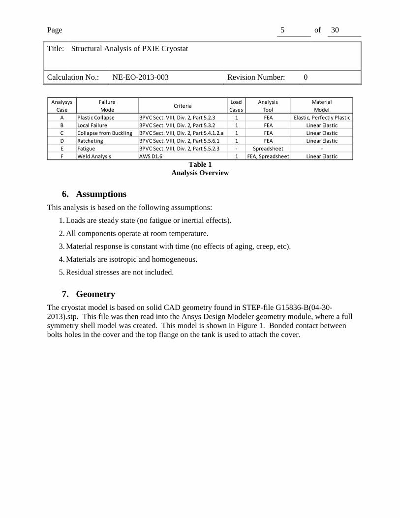
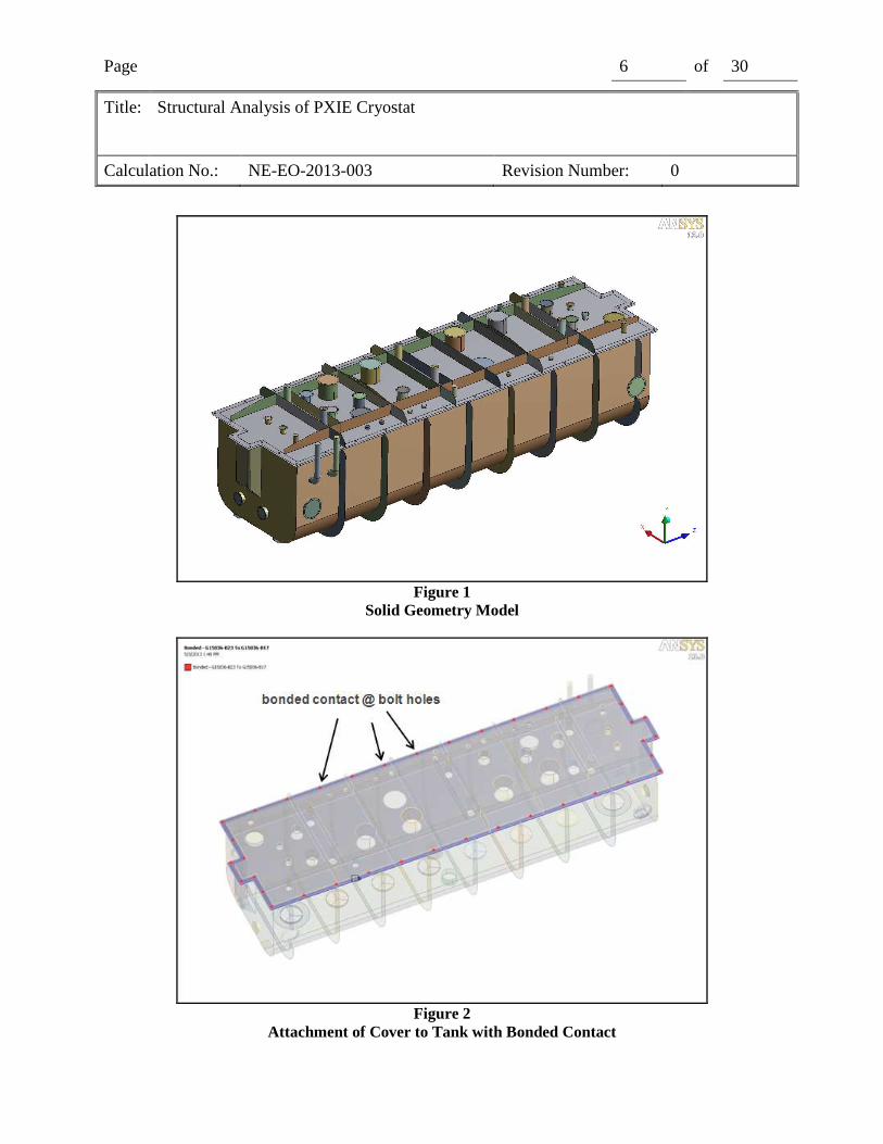
7. Geometry The cryostat model is based on solid CAD geometry found in STEP-file G15836-B(04-30-2013).stp. This file was then read into the Ansys Design Modeler geometry module, where a full symmetry shell model was created. This model is shown in Figure 1. Bonded contact between bolts holes in the cover and the top flange on the tank is used to attach the cover.
Page 6 of 30
Title: Structural Analysis of PXIE Cryostat
Calculation No.: NE-EO-2013-003 Revision Number: 0
Figure 1
Solid Geometry Model
Figure 2
Attachment of Cover to Tank with Bonded Contact
Page 7 of 30
Title: Structural Analysis of PXIE Cryostat
Calculation No.: NE-EO-2013-003 Revision Number: 0
8. Material Properties The cryostat is fabricated from 304L stainless steel that is certified to 304 stainless steel mechanical properties. Material properties used in this analysis are given in Table 2.
Property Value Source
ρρρρ (lb/in3) 0.286 Ref. 5
E(psi) 29.0 x10⁶
Ref. 5
νννν 0.27 Ref. 5
Su (psi) 70,000 Ref. 4
Sy (psi) 30,000 Ref. 4
S (psi) 20,000 Ref. 4
Sps (psi) 60,000 Ref. 2, 5.5.6.1.d Table 2
Material Properties Multiples of these values are used throughout this report and are tabulated below.
Sy (psi) Su (psi) S (psi) 1.5S (psi) 2Su (psi) 3S (psi) 4S (psi)
30,000 70,000 20,000 30,000 60,000 60,000 80,000 Table 3
Multiples of Material Properties
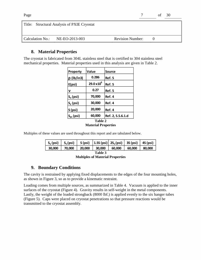
9. Boundary Conditions The cavity is restrained by applying fixed displacements to the edges of the four mounting holes, as shown in Figure 3, so as to provide a kinematic restraint.
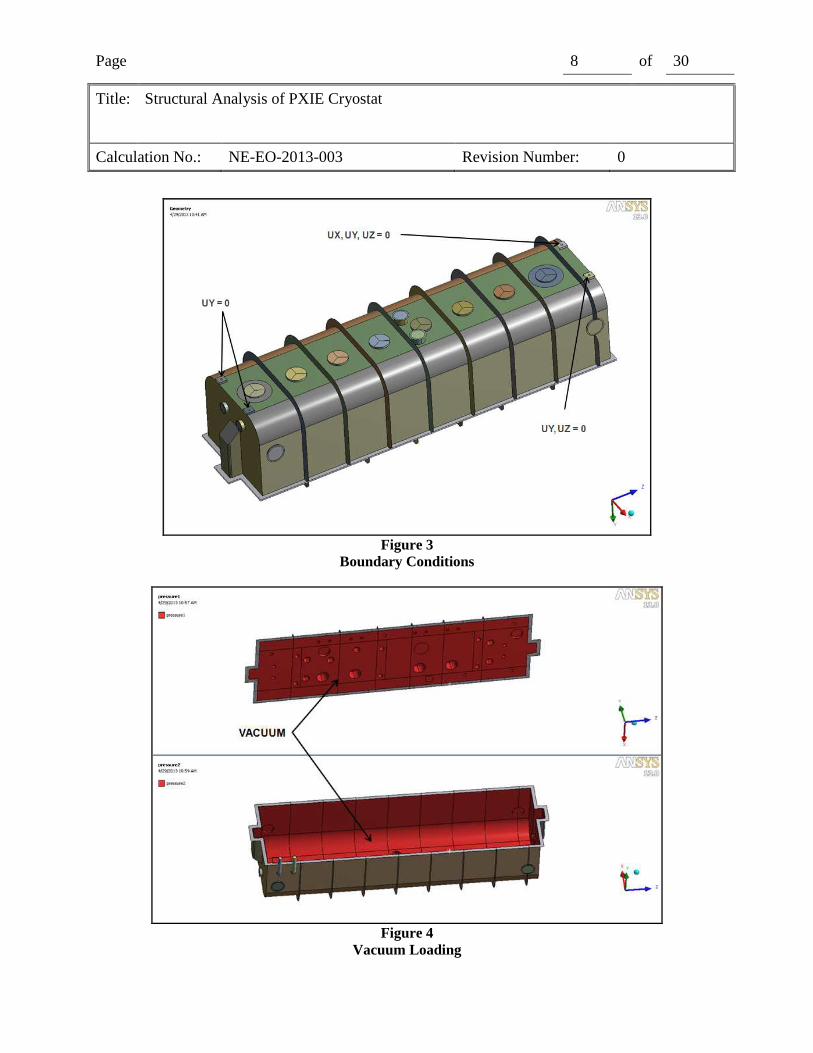
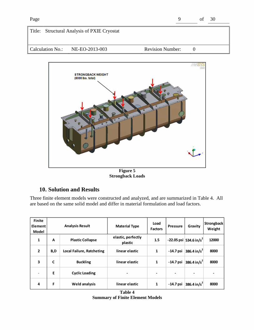
Loading comes from multiple sources, as summarized in Table 4. Vacuum is applied to the inner surfaces of the cryostat (Figure 4). Gravity results in self-weight in the metal components. Lastly, the weight of the loaded strongback (8000 lbf.) is applied evenly to the six hanger tubes (Figure 5). Caps were placed on cryostat penetrations so that pressure reactions would be transmitted to the cryostat assembly.
Page 8 of 30
Title: Structural Analysis of PXIE Cryostat
Calculation No.: NE-EO-2013-003 Revision Number: 0
Figure 3
Boundary Conditions
Figure 4
Vacuum Loading
Page 9 of 30
Title: Structural Analysis of PXIE Cryostat
Calculation No.: NE-EO-2013-003 Revision Number: 0
Figure 5
Strongback Loads
10. Solution and Results Three finite element models were constructed and analyzed, and are summarized in Table 4. All are based on the same solid model and differ in material formulation and load factors.
Finite
Element
Model
Material TypeLoad
FactorsPressure Gravity
Strongback
Weight
1 A Plastic Collapseelastic, perfectly
plastic1.5 -22.05 psi 534.6 in/s
212000
2 B,D Local Failure, Ratcheting linear elastic 1 -14.7 psi 386.4 in/s2
8000
3 C Buckling linear elastic 1 -14.7 psi 386.4 in/s2
8000
- E Cyclic Loading - - - - -
4 F Weld analysis linear elastic 1 -14.7 psi 386.4 in/s2
8000
Analysis Result
Table 4
Summary of Finite Element Models
Page 10 of 30
Title: Structural Analysis of PXIE Cryostat
Calculation No.: NE-EO-2013-003 Revision Number: 0
A. Protection Against Plastic Collapse
The limit load method was used to check for plastic collapse. This analysis checks for structural instability due to gross plastic deformation. An elastic perfectly plastic material model is used, a factored load is applied, and structural stability is indicated if the solution converges. This method is outlined at 5.2.3 in Ref. 3.
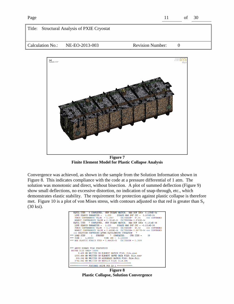
The finite element model 1 in Table 4 was used for this analysis. The shell model was meshed with 112,759 6-node shell elements. This finite element model is shown in Figure 7. The analysis load case is based on load case combinations given in Table 5.4 in Ref. 3. This table specifies five factored load combinations, but in the absence of temperature, snow, wind, seismic and live loads, the last four load case combinations reduce to the first. The factored loads used for this analysis load case are shown in Table 4 .
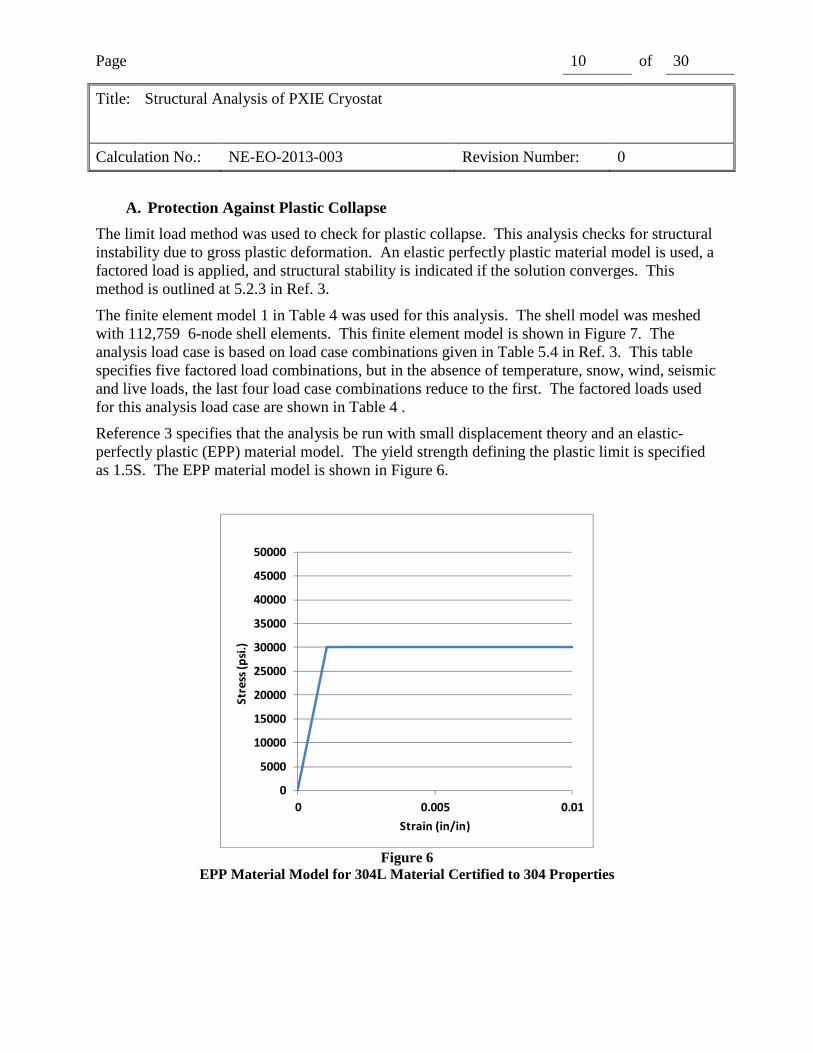
Reference 3 specifies that the analysis be run with small displacement theory and an elastic-perfectly plastic (EPP) material model. The yield strength defining the plastic limit is specified as 1.5S. The EPP material model is shown in Figure 6.
0
5000
10000
15000
20000
25000
30000
35000
40000
45000
50000
0 0.005 0.01
Str
ess
(p
si.)
Strain (in/in)
Figure 6
EPP Material Model for 304L Material Certified to 304 Properties
Page 11 of 30
Title: Structural Analysis of PXIE Cryostat
Calculation No.: NE-EO-2013-003 Revision Number: 0
Figure 7
Finite Element Model for Plastic Collapse Analysis
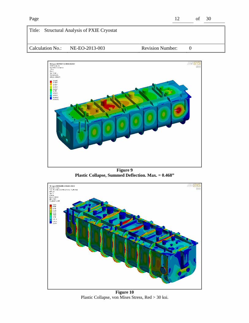
Convergence was achieved, as shown in the sample from the Solution Information shown in Figure 8. This indicates compliance with the code at a pressure differential of 1 atm. The solution was monotonic and direct, without bisection. A plot of summed deflection (Figure 9) show small deflections, no excessive distortion, no indication of snap-through, etc., which demonstrates elastic stability. The requirement for protection against plastic collapse is therefore met. Figure 10 is a plot of von Mises stress, with contours adjusted so that red is greater than Sy (30 ksi).
Figure 8
Plastic Collapse, Solution Convergence
Page 12 of 30
Title: Structural Analysis of PXIE Cryostat
Calculation No.: NE-EO-2013-003 Revision Number: 0
Figure 9
Plastic Collapse, Summed Deflection. Max. = 0.468”
Figure 10
Plastic Collapse, von Mises Stress, Red > 30 ksi.
Page 13 of 30
Title: Structural Analysis of PXIE Cryostat
Calculation No.: NE-EO-2013-003 Revision Number: 0
B. Protection Against Local Failure
Protection from local failure was demonstrated with the Elastic Analysis method in 5.3.2 for Ref. 3. This method is based on a linear elastic model, and the acceptance criterion is that the sum of the three principal stresses be less than 4S.
The finite element model used for the Plastic Collapse analysis was copied and modified to use only linear elastic materials. This is finite element model 2 in Table 4. The analysis load case used in this analysis is shown in Table 4 and is based on Table 5.3 in Ref. 3. This table specifies eight load case combinations, but in the absence of temperature, snow, wind, seismic and live loads, the last seven load case combinations reduce to the first.
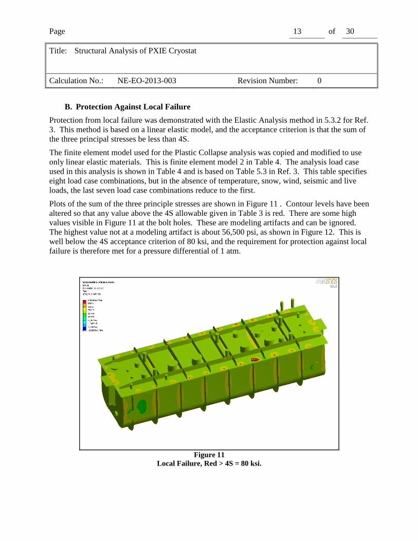
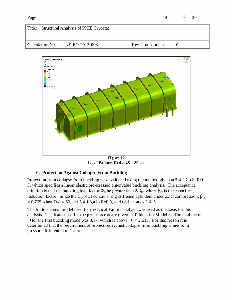
Plots of the sum of the three principle stresses are shown in Figure 11 . Contour levels have been altered so that any value above the 4S allowable given in Table 3 is red. There are some high values visible in Figure 11 at the bolt holes. These are modeling artifacts and can be ignored. The highest value not at a modeling artifact is about 56,500 psi, as shown in Figure 12. This is well below the 4S acceptance criterion of 80 ksi, and the requirement for protection against local failure is therefore met for a pressure differential of 1 atm.
Figure 11
Local Failure, Red > 4S = 80 ksi.
Page 14 of 30
Title: Structural Analysis of PXIE Cryostat
Calculation No.: NE-EO-2013-003 Revision Number: 0
Figure 12
Local Failure, Red > 4S = 80 ksi
C. Protection Against Collapse From Buckling
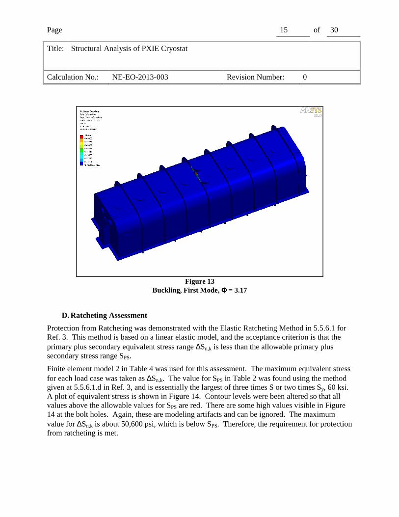
Protection from collapse from buckling was evaluated using the method given at 5.4.1.2.a in Ref. 3, which specifies a linear elastic pre-stressed eigenvalue buckling analysis. The acceptance criterion is that the buckling load factor Φb be greater than 2/βcr, where βcr is the capacity reduction factor. Since the cryostat contains ring-stiffened cylinders under axial compression, βcr = 0.765 when Do/t = 53, per 5.4.1.3,a in Ref. 3, and Φb becomes 2.615.
The finite element model used for the Local Failure analysis was used as the basis for this analysis. The loads used for the prestress run are given in Table 4 for Model 3. The load factor Φ for the first buckling mode was 3.17, which is above Φb = 2.615. For this reason it is determined that the requirement of protection against collapse from buckling is met for a pressure differential of 1 atm.
Page 15 of 30
Title: Structural Analysis of PXIE Cryostat
Calculation No.: NE-EO-2013-003 Revision Number: 0
Figure 13
Buckling, First Mode, ΦΦΦΦ = 3.17
D. Ratcheting Assessment
Protection from Ratcheting was demonstrated with the Elastic Ratcheting Method in 5.5.6.1 for Ref. 3. This method is based on a linear elastic model, and the acceptance criterion is that the primary plus secondary equivalent stress range ∆Sn,k is less than the allowable primary plus secondary stress range SPS.
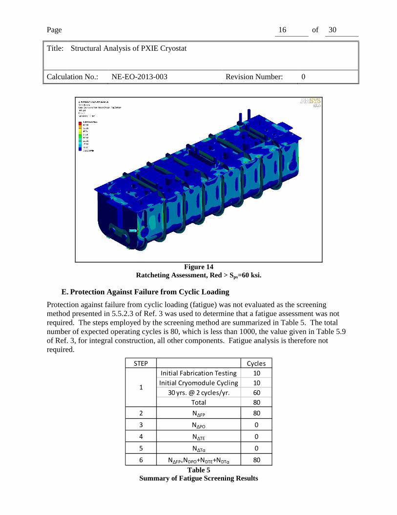
Finite element model 2 in Table 4 was used for this assessment. The maximum equivalent stress for each load case was taken as ∆Sn,k. The value for SPS in Table 2 was found using the method given at 5.5.6.1.d in Ref. 3, and is essentially the largest of three times S or two times Sy, 60 ksi. A plot of equivalent stress is shown in Figure 14. Contour levels were been altered so that all values above the allowable values for SPS are red. There are some high values visible in Figure 14 at the bolt holes. Again, these are modeling artifacts and can be ignored. The maximum value for ∆Sn,k is about 50,600 psi, which is below SPS. Therefore, the requirement for protection from ratcheting is met.
Page 16 of 30
Title: Structural Analysis of PXIE Cryostat
Calculation No.: NE-EO-2013-003 Revision Number: 0
Figure 14
Ratcheting Assessment, Red > Sps=60 ksi.
E. Protection Against Failure from Cyclic Loading
Protection against failure from cyclic loading (fatigue) was not evaluated as the screening method presented in 5.5.2.3 of Ref. 3 was used to determine that a fatigue assessment was not required. The steps employed by the screening method are summarized in Table 5. The total number of expected operating cycles is 80, which is less than 1000, the value given in Table 5.9 of Ref. 3, for integral construction, all other components. Fatigue analysis is therefore not required.
STEP Cycles
Initial Fabrication Testing 10
Initial Cryomodule Cycling 10
30 yrs. @ 2 cycles/yr. 60
Total 80
2 N∆FP 80
3 N∆PO 0
4 N∆TE 0
5 N∆Tα 0
6 N∆FP+NDPO+NDTE+NDTα 80
1
Table 5
Summary of Fatigue Screening Results
Page 17 of 30
Title: Structural Analysis of PXIE Cryostat
Calculation No.: NE-EO-2013-003 Revision Number: 0
F. Weld Analysis
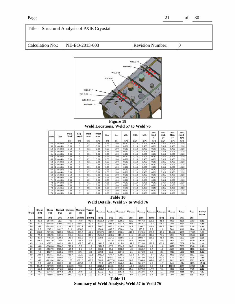
A weld schedule was not available at the time of this analysis, so weld configurations were determined by the analyst. Welds were selected for evaluation by inspecting plots of von Mises stress and deflection, and selecting representative welds in high stress and high deflection locations. Symmetry considerations were used to eliminate redundant calculations.
To evaluate these welds, the weld reactions were found by summing the nodal reactions of the nodes at the weld interface and finding their moments about the weld centroid. These reactions were then used to calculate normal and shear stresses, using the methods outlined in Ref. 4. These stresses were then compared to an allowable value determined per Ref. 5. The weld filler to be used for construction has not been determined, so the filler specified in Table 3.3 in Ref. 5 was used for this analysis.
Welds 1 through 86 are double-sided fillet skip welds. All weld sizes started at a nominal ¼” and were increased as needed to get an acceptable safety factor, providing that the weld size did not exceed the thickness of the thinnest plate in the weld. The throat dimension was taken as 0.707 times the weld size. All stresses were treated as shear stresses, per Ref. 7, so the normal and shear components were combined with the square-root-sum-of-squares method to get a single value for comparison to the allowable.
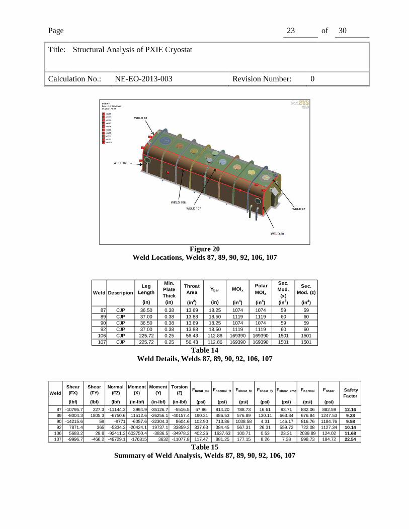
Welds 87 through 92, 106 and 107 are continuous complete joint penetration groove welds. All weld sizes are equal to the thickness of the thinnest plate in the weld, and the throat dimension was taken as the weld size. The first principal stress and maximum shear stress were derived from the calculated weld stress and compared to the allowables in Ref. 7.
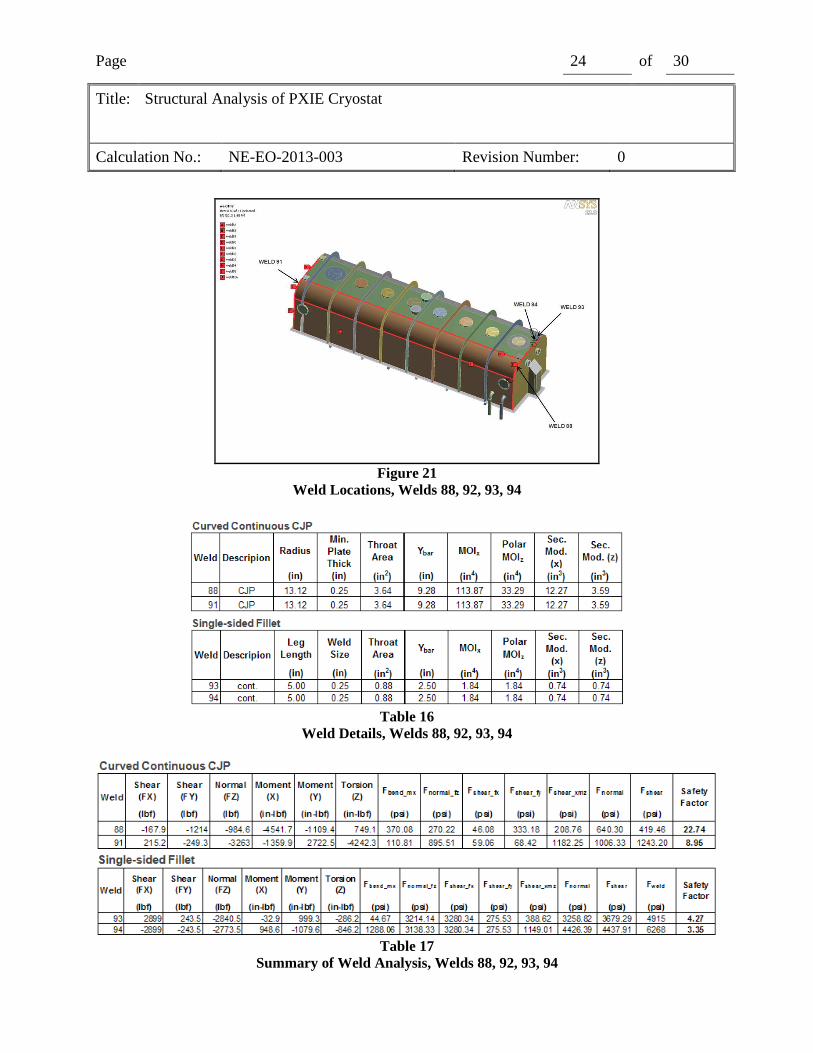
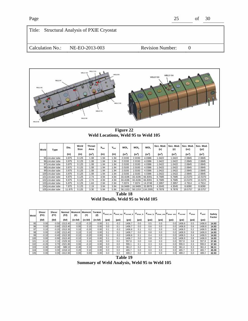
Welds 93 through 105 are continuous single-sided fillet welds. Welds 93 and 94 attach one of the mounting channels. The weld size for these welds is ¼”, based on the thickness of the channel flange. The remaining welds are at penetrations made from round tubing with a 0.120” wall, so the weld size was set to 1/8”. Again, the throat dimension was taken as 0.707 times the weld size. All stresses were treated as shear stresses, so the normal and shear components were combined by SRSS to get a single value for comparison to the allowable.
Weld locations are identified in Figure 15 through Figure 21. Weld details and weld analysis result summaries are given in Table 6 through Table 19. All weld results show a factor of safety greater than 1 at a pressure differential of 1 atm.
Page 18 of 30
Title: Structural Analysis of PXIE Cryostat
Calculation No.: NE-EO-2013-003 Revision Number: 0
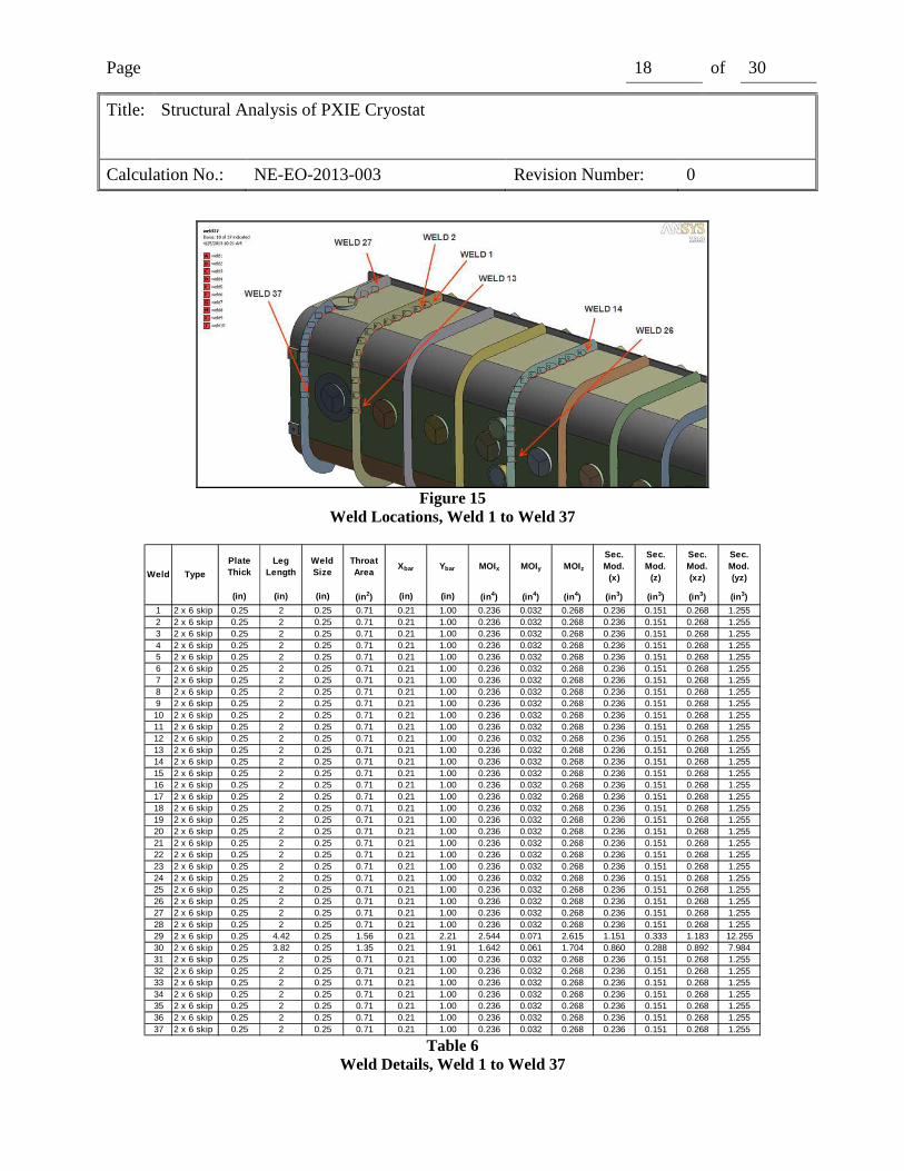
Figure 15
Weld Locations, Weld 1 to Weld 37
Plate Thick
Leg Length
Weld Size
Throat Area
Xbar Ybar MOIx MOIy MOIz
Sec. Mod.
(x)
Sec. Mod.
(z)
Sec. Mod. (xz)
Sec. Mod. (yz)
(in) (in) (in) (in2) (in) (in) (in4) (in4) (in4) (in3) (in3) (in3) (in3)
1 2 x 6 skip 0.25 2 0.25 0.71 0.21 1.00 0.236 0.032 0.268 0.236 0.151 0.268 1.2552 2 x 6 skip 0.25 2 0.25 0.71 0.21 1.00 0.236 0.032 0.268 0.236 0.151 0.268 1.2553 2 x 6 skip 0.25 2 0.25 0.71 0.21 1.00 0.236 0.032 0.268 0.236 0.151 0.268 1.2554 2 x 6 skip 0.25 2 0.25 0.71 0.21 1.00 0.236 0.032 0.268 0.236 0.151 0.268 1.2555 2 x 6 skip 0.25 2 0.25 0.71 0.21 1.00 0.236 0.032 0.268 0.236 0.151 0.268 1.2556 2 x 6 skip 0.25 2 0.25 0.71 0.21 1.00 0.236 0.032 0.268 0.236 0.151 0.268 1.2557 2 x 6 skip 0.25 2 0.25 0.71 0.21 1.00 0.236 0.032 0.268 0.236 0.151 0.268 1.2558 2 x 6 skip 0.25 2 0.25 0.71 0.21 1.00 0.236 0.032 0.268 0.236 0.151 0.268 1.2559 2 x 6 skip 0.25 2 0.25 0.71 0.21 1.00 0.236 0.032 0.268 0.236 0.151 0.268 1.25510 2 x 6 skip 0.25 2 0.25 0.71 0.21 1.00 0.236 0.032 0.268 0.236 0.151 0.268 1.25511 2 x 6 skip 0.25 2 0.25 0.71 0.21 1.00 0.236 0.032 0.268 0.236 0.151 0.268 1.25512 2 x 6 skip 0.25 2 0.25 0.71 0.21 1.00 0.236 0.032 0.268 0.236 0.151 0.268 1.25513 2 x 6 skip 0.25 2 0.25 0.71 0.21 1.00 0.236 0.032 0.268 0.236 0.151 0.268 1.25514 2 x 6 skip 0.25 2 0.25 0.71 0.21 1.00 0.236 0.032 0.268 0.236 0.151 0.268 1.25515 2 x 6 skip 0.25 2 0.25 0.71 0.21 1.00 0.236 0.032 0.268 0.236 0.151 0.268 1.25516 2 x 6 skip 0.25 2 0.25 0.71 0.21 1.00 0.236 0.032 0.268 0.236 0.151 0.268 1.25517 2 x 6 skip 0.25 2 0.25 0.71 0.21 1.00 0.236 0.032 0.268 0.236 0.151 0.268 1.25518 2 x 6 skip 0.25 2 0.25 0.71 0.21 1.00 0.236 0.032 0.268 0.236 0.151 0.268 1.25519 2 x 6 skip 0.25 2 0.25 0.71 0.21 1.00 0.236 0.032 0.268 0.236 0.151 0.268 1.25520 2 x 6 skip 0.25 2 0.25 0.71 0.21 1.00 0.236 0.032 0.268 0.236 0.151 0.268 1.25521 2 x 6 skip 0.25 2 0.25 0.71 0.21 1.00 0.236 0.032 0.268 0.236 0.151 0.268 1.25522 2 x 6 skip 0.25 2 0.25 0.71 0.21 1.00 0.236 0.032 0.268 0.236 0.151 0.268 1.25523 2 x 6 skip 0.25 2 0.25 0.71 0.21 1.00 0.236 0.032 0.268 0.236 0.151 0.268 1.25524 2 x 6 skip 0.25 2 0.25 0.71 0.21 1.00 0.236 0.032 0.268 0.236 0.151 0.268 1.25525 2 x 6 skip 0.25 2 0.25 0.71 0.21 1.00 0.236 0.032 0.268 0.236 0.151 0.268 1.25526 2 x 6 skip 0.25 2 0.25 0.71 0.21 1.00 0.236 0.032 0.268 0.236 0.151 0.268 1.25527 2 x 6 skip 0.25 2 0.25 0.71 0.21 1.00 0.236 0.032 0.268 0.236 0.151 0.268 1.25528 2 x 6 skip 0.25 2 0.25 0.71 0.21 1.00 0.236 0.032 0.268 0.236 0.151 0.268 1.25529 2 x 6 skip 0.25 4.42 0.25 1.56 0.21 2.21 2.544 0.071 2.615 1.151 0.333 1.183 12.25530 2 x 6 skip 0.25 3.82 0.25 1.35 0.21 1.91 1.642 0.061 1.704 0.860 0.288 0.892 7.98431 2 x 6 skip 0.25 2 0.25 0.71 0.21 1.00 0.236 0.032 0.268 0.236 0.151 0.268 1.25532 2 x 6 skip 0.25 2 0.25 0.71 0.21 1.00 0.236 0.032 0.268 0.236 0.151 0.268 1.25533 2 x 6 skip 0.25 2 0.25 0.71 0.21 1.00 0.236 0.032 0.268 0.236 0.151 0.268 1.25534 2 x 6 skip 0.25 2 0.25 0.71 0.21 1.00 0.236 0.032 0.268 0.236 0.151 0.268 1.25535 2 x 6 skip 0.25 2 0.25 0.71 0.21 1.00 0.236 0.032 0.268 0.236 0.151 0.268 1.25536 2 x 6 skip 0.25 2 0.25 0.71 0.21 1.00 0.236 0.032 0.268 0.236 0.151 0.268 1.25537 2 x 6 skip 0.25 2 0.25 0.71 0.21 1.00 0.236 0.032 0.268 0.236 0.151 0.268 1.255
Weld Type
Table 6
Weld Details, Weld 1 to Weld 37
Page 19 of 30
Title: Structural Analysis of PXIE Cryostat
Calculation No.: NE-EO-2013-003 Revision Number: 0
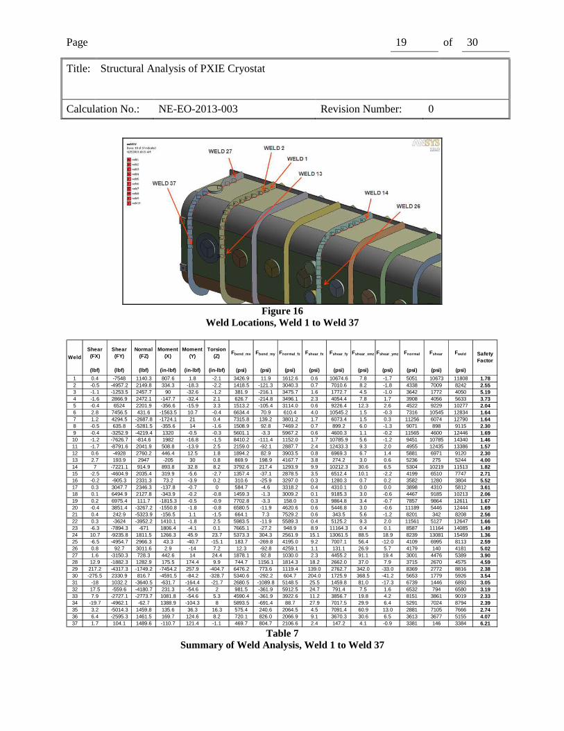
Figure 16
Weld Locations, Weld 1 to Weld 37
Shear (FX)
Shear (FY)
Normal (FZ)
Moment (X)
Moment (Y)
Torsion (Z)
Fbend_mx Fbend_my Fnormal_fz Fshear_fx Fshear_fy Fshear_xmz Fshear_ymz Fnormal Fshear Fweld
(lbf) (lbf) (lbf) (in-lbf) (in-lbf) (in-lbf) (psi) (psi) (psi) (psi) (psi) (psi) (psi) (psi) (psi) (psi)
1 0.4 -7548 1140.3 807.6 1.8 -2.1 3426.9 11.9 1612.6 0.6 10674.6 7.8 -1.7 5051 10673 11808 1.782 -0.5 -4957.2 2149.8 334.3 -18.3 -2.2 1418.5 -121.3 3040.3 0.7 7010.6 8.2 -1.8 4338 7009 8242 2.553 -1.1 -1253.5 2457.7 90 -32.6 -1.2 381.9 -216.1 3475.7 1.6 1772.7 4.5 -1.0 3642 1772 4050 5.194 -1.6 2866.9 2472.1 -147.7 -32.4 2.1 626.7 -214.8 3496.1 2.3 4054.4 7.8 1.7 3908 4056 5633 3.735 -0.4 6524 2201.9 -356.6 -15.9 3.3 1513.2 -105.4 3114.0 0.6 9226.4 12.3 2.6 4522 9229 10277 2.046 2.8 7456.5 431.6 -1563.5 10.7 -0.4 6634.4 70.9 610.4 4.0 10545.2 1.5 -0.3 7316 10545 12834 1.647 1.2 4294.5 -2687.8 -1724.1 21 0.4 7315.8 139.2 3801.2 1.7 6073.4 1.5 0.3 11256 6074 12790 1.648 -0.5 635.8 -5281.5 -355.6 14 -1.6 1508.9 92.8 7469.2 0.7 899.2 6.0 -1.3 9071 898 9115 2.309 -0.4 -3252.9 -4219.4 1320 -0.5 -0.3 5601.1 -3.3 5967.2 0.6 4600.3 1.1 -0.2 11565 4600 12446 1.6910 -1.2 -7626.7 -814.6 1982 -16.8 -1.5 8410.2 -111.4 1152.0 1.7 10785.9 5.6 -1.2 9451 10785 14340 1.4611 -1.7 -8791.6 2041.9 508.8 -13.9 2.5 2159.0 -92.1 2887.7 2.4 12433.3 9.3 2.0 4955 12435 13386 1.5712 0.6 -4928 2760.2 446.4 12.5 1.8 1894.2 82.9 3903.5 0.8 6969.3 6.7 1.4 5881 6971 9120 2.3013 2.7 193.9 2947 -205 30 0.8 869.9 198.9 4167.7 3.8 274.2 3.0 0.6 5236 275 5244 4.0014 7 -7221.1 914.9 893.8 32.8 8.2 3792.6 217.4 1293.9 9.9 10212.3 30.6 6.5 5304 10219 11513 1.8215 -2.5 -4604.9 2035.4 319.9 -5.6 -2.7 1357.4 -37.1 2878.5 3.5 6512.4 10.1 -2.2 4199 6510 7747 2.7116 -0.2 -905.3 2331.3 73.2 -3.9 0.2 310.6 -25.9 3297.0 0.3 1280.3 0.7 0.2 3582 1280 3804 5.5217 0.3 3047.7 2346.3 -137.8 -0.7 0 584.7 -4.6 3318.2 0.4 4310.1 0.0 0.0 3898 4310 5812 3.6118 0.1 6494.9 2127.8 -343.9 -0.2 -0.8 1459.3 -1.3 3009.2 0.1 9185.3 3.0 -0.6 4467 9185 10213 2.0619 0.2 6975.4 111.7 -1815.3 -0.5 -0.9 7702.8 -3.3 158.0 0.3 9864.8 3.4 -0.7 7857 9864 12611 1.6720 -0.4 3851.4 -3267.2 -1550.8 -1.8 -0.8 6580.5 -11.9 4620.6 0.6 5446.8 3.0 -0.6 11189 5446 12444 1.6921 0.4 242.9 -5323.9 -156.5 1.1 -1.5 664.1 7.3 7529.2 0.6 343.5 5.6 -1.2 8201 342 8208 2.5622 0.3 -3624 -3952.2 1410.1 -1.8 2.5 5983.5 -11.9 5589.3 0.4 5125.2 9.3 2.0 11561 5127 12647 1.6623 -6.3 -7894.3 -671 1806.4 -4.1 0.1 7665.1 -27.2 948.9 8.9 11164.3 0.4 0.1 8587 11164 14085 1.4924 10.7 -9235.8 1811.5 1266.3 45.9 23.7 5373.3 304.3 2561.9 15.1 13061.5 88.5 18.9 8239 13081 15459 1.3625 -6.5 -4954.7 2966.3 43.3 -40.7 -15.1 183.7 -269.8 4195.0 9.2 7007.1 56.4 -12.0 4109 6995 8113 2.5926 0.8 92.7 3011.6 2.9 -14 7.2 12.3 -92.8 4259.1 1.1 131.1 26.9 5.7 4179 140 4181 5.0227 1.6 -3150.3 728.3 442.6 14 24.4 1878.1 92.8 1030.0 2.3 4455.2 91.1 19.4 3001 4476 5389 3.9028 12.9 -1882.3 1282.9 175.5 174.4 9.9 744.7 1156.1 1814.3 18.2 2662.0 37.0 7.9 3715 2670 4575 4.5929 217.2 -4317.3 -1749.2 -7454.2 257.9 -404.7 6476.2 773.6 1119.4 139.0 2762.7 342.0 -33.0 8369 2772 8816 2.3830 -275.5 2330.9 816.7 -4591.5 -84.2 -328.7 5340.6 -292.2 604.7 204.0 1725.9 368.5 -41.2 5653 1779 5926 3.5431 -18 1032.2 -3640.5 -631.7 -164.4 -21.7 2680.5 -1089.8 5148.5 25.5 1459.8 81.0 -17.3 6739 1446 6893 3.0532 17.5 -559.6 -4180.7 231.3 -54.6 2 981.5 -361.9 5912.5 24.7 791.4 7.5 1.6 6532 794 6580 3.1933 7.9 -2727.1 -2773.7 1081.8 -54.6 5.3 4590.4 -361.9 3922.6 11.2 3856.7 19.8 4.2 8151 3861 9019 2.3334 -19.7 -4962.1 -62.7 1388.9 -104.3 8 5893.5 -691.4 88.7 27.9 7017.5 29.9 6.4 5291 7024 8794 2.3935 3.2 -5014.3 1459.8 135.6 36.3 16.3 575.4 240.6 2064.5 4.5 7091.4 60.9 13.0 2881 7105 7666 2.7436 6.4 -2595.3 1461.5 169.7 124.6 8.2 720.1 826.0 2066.9 9.1 3670.3 30.6 6.5 3613 3677 5155 4.0737 1.7 104.1 1489.6 -110.7 121.4 -1.1 469.7 804.7 2106.6 2.4 147.2 4.1 -0.9 3381 146 3384 6.21
WeldSafety Factor
Table 7
Summary of Weld Analysis, Weld 1 to Weld 37
Page 20 of 30
Title: Structural Analysis of PXIE Cryostat
Calculation No.: NE-EO-2013-003 Revision Number: 0
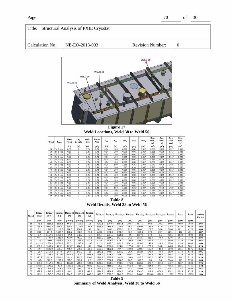
Figure 17
Weld Locations, Weld 38 to Weld 56
Plate Thick
Leg Length
Weld Size
Throat Area
Xbar Ybar MOIx MOIy MOIz
Sec. Mod.
(x)
Sec. Mod.
(z)
Sec. Mod. (xz)
Sec. Mod. (yz)
(in) (in) (in) (in2) (in) (in) (in4) (in4) (in4) (in3) (in3) (in3) (in3)38 2 x 6 skip 0.50 2 0.25 0.71 0.34 1.00 0.236 0.081 0.317 0.236 0.239 0.317 0.93639 2 x 6 skip 0.50 2 0.25 0.71 0.34 1.00 0.236 0.081 0.317 0.236 0.239 0.317 0.93640 2 x 6 skip 0.50 2 0.25 0.71 0.34 1.00 0.236 0.081 0.317 0.236 0.239 0.317 0.93641 2 x 6 skip 0.50 2 0.25 0.71 0.34 1.00 0.236 0.081 0.317 0.236 0.239 0.317 0.93642 2 x 6 skip 0.50 2 0.25 0.71 0.34 1.00 0.236 0.081 0.317 0.236 0.239 0.317 0.93643 2 x 6 skip 0.50 2 0.25 0.71 0.34 1.00 0.236 0.081 0.317 0.236 0.239 0.317 0.93644 2 x 6 skip 0.50 4 0.25 1.41 0.34 2.00 1.885 0.162 2.047 0.943 0.478 1.024 6.05045 2 x 6 skip 0.50 4 0.25 1.41 0.34 2.00 1.885 0.162 2.047 0.943 0.478 1.024 6.05046 2 x 6 skip 0.50 2 0.25 0.71 0.34 1.00 0.236 0.081 0.317 0.236 0.239 0.317 0.93647 2 x 6 skip 0.50 2 0.25 0.71 0.34 1.00 0.236 0.081 0.317 0.236 0.239 0.317 0.93648 2 x 6 skip 0.50 2 0.25 0.71 0.34 1.00 0.236 0.081 0.317 0.236 0.239 0.317 0.93649 2 x 6 skip 0.50 4 0.25 1.41 0.34 2.00 1.885 0.162 2.047 0.943 0.478 1.024 6.05050 2 x 6 skip 0.50 2 0.25 0.71 0.34 1.00 0.236 0.081 0.317 0.236 0.239 0.317 0.93651 2 x 6 skip 0.50 2 0.25 0.71 0.34 1.00 0.236 0.081 0.317 0.236 0.239 0.317 0.93652 2 x 6 skip 0.50 2 0.25 0.71 0.34 1.00 0.236 0.081 0.317 0.236 0.239 0.317 0.93653 2 x 6 skip 0.50 4 0.25 1.41 0.34 2.00 1.885 0.162 2.047 0.943 0.478 1.024 6.05054 2 x 6 skip 0.50 2 0.25 0.71 0.34 1.00 0.236 0.081 0.317 0.236 0.239 0.317 0.93655 2 x 6 skip 0.50 2 0.25 0.71 0.34 1.00 0.236 0.081 0.317 0.236 0.239 0.317 0.93656 2 x 6 skip 0.50 2 0.25 0.71 0.34 1.00 0.236 0.081 0.317 0.236 0.239 0.317 0.936
Weld Type
Table 8
Weld Details, Weld 38 to Weld 56
Shear (FX)
Shear (FY)
Normal (FZ)
Moment (X)
Moment (Y)
Torsion (Z)
Fbend_mx Fbend_my Fnormal_fz Fshear_fx Fshear_fy Fshear_xmz Fshear_ymz Fnormal Fshear Fweld
(lbf) (lbf) (lbf) (in-lbf) (in-lbf) (in-lbf) (psi) (psi) (psi) (psi) (psi) (psi) (psi) (psi) (psi) (psi)38 -71.2 -3236.6 -2675.5 -952.4 -325.2 18 4041.3 -1359.4 3783.8 100.7 4577.3 56.9 19.2 6466 4599 7935 2.6539 -25.6 -4362.7 236.1 810.3 -236.5 57.9 3438.3 -988.6 333.9 36.2 6169.8 182.9 61.9 2784 6236 6829 3.0840 8.1 -1941.8 1113.7 226.5 130.2 55 961.1 544.2 1575.0 11.5 2746.1 173.7 58.8 3080 2811 4170 5.0441 23.2 -261.5 1407.7 176.7 370.9 27.8 749.8 1550.4 1990.8 32.8 369.8 87.8 29.7 4291 417 4311 4.8742 6.7 1157.6 1858.3 27.2 372.7 -5.4 115.4 1557.9 2628.1 9.5 1637.1 17.1 -5.8 4301 1632 4600 4.5643 66.7 2780.8 1221.3 -620.5 451.2 -70.1 2633.0 1886.0 1727.2 94.3 3932.7 221.4 -74.9 6246 3871 7348 2.8644 1122.2 -660 -1295.7 409 1055.6 437.6 433.9 2206.2 916.2 793.5 466.7 427.5 72.3 3556 1335 3799 5.5345 2321.3 -1751.1 -2011.9 -577.2 2145.9 -147 612.3 4485.0 1422.6 1641.4 1238.2 143.6 -24.3 6520 2159 6868 3.0646 121.6 1563.6 -229.1 -225.2 766.3 88 955.6 3203.2 324.0 172.0 2211.3 277.9 94.0 4483 2349 5061 4.1547 72.7 1831.9 351.9 445.4 746.9 -36.8 1890.0 3122.1 497.7 102.8 2590.7 116.2 -39.3 5510 2561 6076 3.4648 -18.7 2710.2 1473 -269.4 141.7 -56 1143.1 592.3 2083.2 26.4 3832.8 176.9 -59.8 3819 3778 5372 3.9149 1361 2335.3 -522.9 -1478.3 979 -503.9 1568.2 2046.1 369.7 962.4 1651.3 492.3 -83.3 3984 2139 4522 4.6450 130.7 -302.4 -256.3 412.4 702.3 136.2 1749.9 2935.7 362.5 184.8 427.7 430.2 145.6 5048 841 5118 4.1051 14.5 218.3 1287.3 305.3 629.2 2.8 1295.5 2630.1 1820.5 20.5 308.7 8.8 3.0 5746 313 5755 3.6552 124.3 1157.4 417.6 -835.8 789.5 -104.4 3546.5 3300.2 590.6 175.8 1636.8 329.7 -111.6 7437 1607 7609 2.7653 1366.6 -1045.8 -40.4 1892.1 1013.6 403.3 2007.2 2118.5 28.6 966.3 739.5 394.0 66.7 4154 1581 4445 4.7254 -23.8 -1548.4 1018.4 -359.3 249.2 54.5 1524.6 1041.7 1440.2 33.7 2189.8 172.1 58.2 4007 2257 4599 4.5755 189.2 -1812.8 -1363.7 -642 1133.7 -99.3 2724.2 4738.9 1928.6 267.6 2563.7 313.6 -106.1 9392 2525 9725 2.1656 1852 -1745.5 -2646.2 264.8 1680.6 -867.2 1123.6 7025.0 3742.3 2619.1 2468.5 2739.0 -926.8 11891 5576 13133 1.60
WeldSafety Factor
Table 9
Summary of Weld Analysis, Weld 38 to Weld 56
Page 21 of 30
Title: Structural Analysis of PXIE Cryostat
Calculation No.: NE-EO-2013-003 Revision Number: 0
Figure 18
Weld Locations, Weld 57 to Weld 76
Plate Thick
Leg Length
Weld Size
Throat Area
Xbar Ybar MOIx MOIy MOIz
Sec. Mod.
(x)
Sec. Mod.
(z)
Sec. Mod. (xz)
Sec. Mod. (yz)
(in) (in) (in) (in2) (in) (in) (in4) (in4) (in4) (in3) (in3) (in3) (in3)57 2 x 6 skip 0.50 2 0.31 0.88 0.36 1.00 0.292 0.113 0.406 0.292 0.315 0.406 1.12858 2 x 6 skip 0.50 2 0.31 0.88 0.36 1.00 0.292 0.113 0.406 0.292 0.315 0.406 1.12859 2 x 6 skip 0.50 2 0.31 0.88 0.36 1.00 0.292 0.113 0.406 0.292 0.315 0.406 1.12860 2 x 6 skip 0.50 2 0.31 0.88 0.36 1.00 0.292 0.113 0.406 0.292 0.315 0.406 1.12861 2 x 6 skip 0.50 2 0.31 0.88 0.36 1.00 0.292 0.113 0.406 0.292 0.315 0.406 1.12862 2 x 6 skip 0.50 2 0.31 0.88 0.36 1.00 0.292 0.113 0.406 0.292 0.315 0.406 1.12863 2 x 6 skip 0.50 2 0.31 0.88 0.36 1.00 0.292 0.113 0.406 0.292 0.315 0.406 1.12864 2 x 6 skip 0.50 2 0.31 0.88 0.36 1.00 0.292 0.113 0.406 0.292 0.315 0.406 1.12865 2 x 6 skip 0.50 2 0.31 0.88 0.36 1.00 0.292 0.113 0.406 0.292 0.315 0.406 1.12866 2 x 6 skip 0.50 2 0.31 0.88 0.36 1.00 0.292 0.113 0.406 0.292 0.315 0.406 1.12867 2 x 6 skip 0.50 2 0.31 0.88 0.36 1.00 0.292 0.113 0.406 0.292 0.315 0.406 1.12868 2 x 6 skip 0.50 2 0.31 0.88 0.36 1.00 0.292 0.113 0.406 0.292 0.315 0.406 1.12869 2 x 6 skip 0.50 2 0.31 0.88 0.36 1.00 0.292 0.113 0.406 0.292 0.315 0.406 1.12870 2 x 6 skip 0.50 2 0.31 0.88 0.36 1.00 0.292 0.113 0.406 0.292 0.315 0.406 1.12871 2 x 6 skip 0.50 2 0.31 0.88 0.36 1.00 0.292 0.113 0.406 0.292 0.315 0.406 1.12872 2 x 6 skip 0.50 2 0.31 0.88 0.36 1.00 0.292 0.113 0.406 0.292 0.315 0.406 1.12873 2 x 6 skip 0.50 2 0.31 0.88 0.36 1.00 0.292 0.113 0.406 0.292 0.315 0.406 1.12874 2 x 6 skip 0.50 2 0.31 0.88 0.36 1.00 0.292 0.113 0.406 0.292 0.315 0.406 1.12875 2 x 6 skip 0.50 2 0.31 0.88 0.36 1.00 0.292 0.113 0.406 0.292 0.315 0.406 1.12876 2 x 6 skip 0.50 2 0.31 0.88 0.36 1.00 0.292 0.113 0.406 0.292 0.315 0.406 1.128
Weld Type
Table 10
Weld Details, Weld 57 to Weld 76
Shear (FX)
Shear (FY)
Normal (FZ)
Moment (X)
Moment (Y)
Torsion (Z)
Fbend_mx Fbend_my Fnormal_fz Fshear_fx Fshear_fy Fshear_xmz Fshear_ymz Fnormal Fshear Fweld
(lbf) (lbf) (lbf) (in-lbf) (in-lbf) (in-lbf) (psi) (psi) (psi) (psi) (psi) (psi) (psi) (psi) (psi) (psi)57 45.8 -3548.6 1127 738 76.9 91.6 2525.4 243.9 1285.3 52.2 4047.2 225.8 81.2 4055 4138 5793 3.6258 -53.4 -3488.5 1260.7 -243.5 -188.7 -30.1 833.3 -598.6 1437.8 60.9 3978.7 74.2 -26.7 1673 3954 4293 4.8959 -13 -2020.8 810.1 169.7 -201.8 -16.6 580.7 -640.1 923.9 14.8 2304.7 40.9 -14.7 864 2291 2448 8.5860 2.3 -746.1 901.7 51.6 -138.3 -1.1 176.6 -438.7 1028.4 2.6 850.9 2.7 -1.0 766 850 1144 18.3561 438.3 -5374.5 3709.2 3254.6 352.3 44.5 11137.2 1117.6 4230.4 499.9 6129.6 109.7 39.5 16485 6199 17612 1.1962 74.3 -6852.5 2801.3 -751.8 365.9 88.5 2572.7 1160.7 3194.9 84.7 7815.3 218.2 78.5 6928 7900 10507 2.0063 32.9 -4461.8 2366.6 148.9 326.2 47.3 509.5 1034.8 2699.1 37.5 5088.7 116.6 41.9 4243 5133 6660 3.1564 -16.3 -1447.6 1960 64.6 141.2 -4.5 221.1 447.9 2235.4 18.6 1651.0 11.1 -4.0 2904 1647 3339 6.2965 -121.9 -6773 802.3 851.7 -73.7 -70.1 2914.5 -233.8 915.0 139.0 7724.6 172.8 -62.1 3596 7669 8470 2.4866 -8.8 -6369.6 2906.3 752.4 -5.6 -1.8 2574.7 -17.8 3314.7 10.0 7264.6 4.4 -1.6 5872 7263 9340 2.2567 -0.9 -3567.9 3505.9 157.4 9.5 -1.1 538.6 30.1 3998.5 1.0 4069.2 2.7 -1.0 4567 4068 6116 3.4368 4.5 -1027.4 3215.2 -84.9 19.1 -3.5 290.5 60.6 3667.0 5.1 1171.8 8.6 -3.1 4018 1169 4185 5.0269 -280.4 -5035.1 1138.2 721.7 -212.7 -29.5 2469.7 -674.7 1298.1 319.8 5742.6 72.7 -26.2 3093 5730 6511 3.2370 -97 -4883.8 1659.4 -11.1 -458.4 -80.9 38.0 -1454.1 1892.6 110.6 5570.0 199.5 -71.7 476 5507 5528 3.8071 -16 -2814.4 1263.4 175 -371.3 -26.6 598.9 -1177.8 1440.9 18.2 3209.8 65.6 -23.6 862 3187 3302 6.3672 3.9 -890.6 1262.6 22 -275.9 -1.9 75.3 -875.2 1440.0 4.4 1015.7 4.7 -1.7 640 1014 1199 17.5173 104.5 -4078.9 2319.7 2460.5 70.8 3.5 8419.8 224.6 2645.6 119.2 4652.0 8.6 3.1 11290 4657 12213 1.7274 13.8 -5352.2 2442.9 -358.1 77 -6.9 1225.4 244.3 2786.1 15.7 6104.2 17.0 -6.1 4256 6098 7436 2.8275 -0.2 -3346.3 1546.5 181.5 25.5 -1.9 621.1 80.9 1763.8 0.2 3816.5 4.7 -1.7 2466 3815 4542 4.6276 -4.3 -1150 1546.8 50.1 -19.3 -2.3 171.4 -61.2 1764.1 4.9 1311.6 5.7 -2.0 1874 1310 2287 9.18
WeldSafety Factor
Table 11
Summary of Weld Analysis, Weld 57 to Weld 76
Page 22 of 30
Title: Structural Analysis of PXIE Cryostat
Calculation No.: NE-EO-2013-003 Revision Number: 0
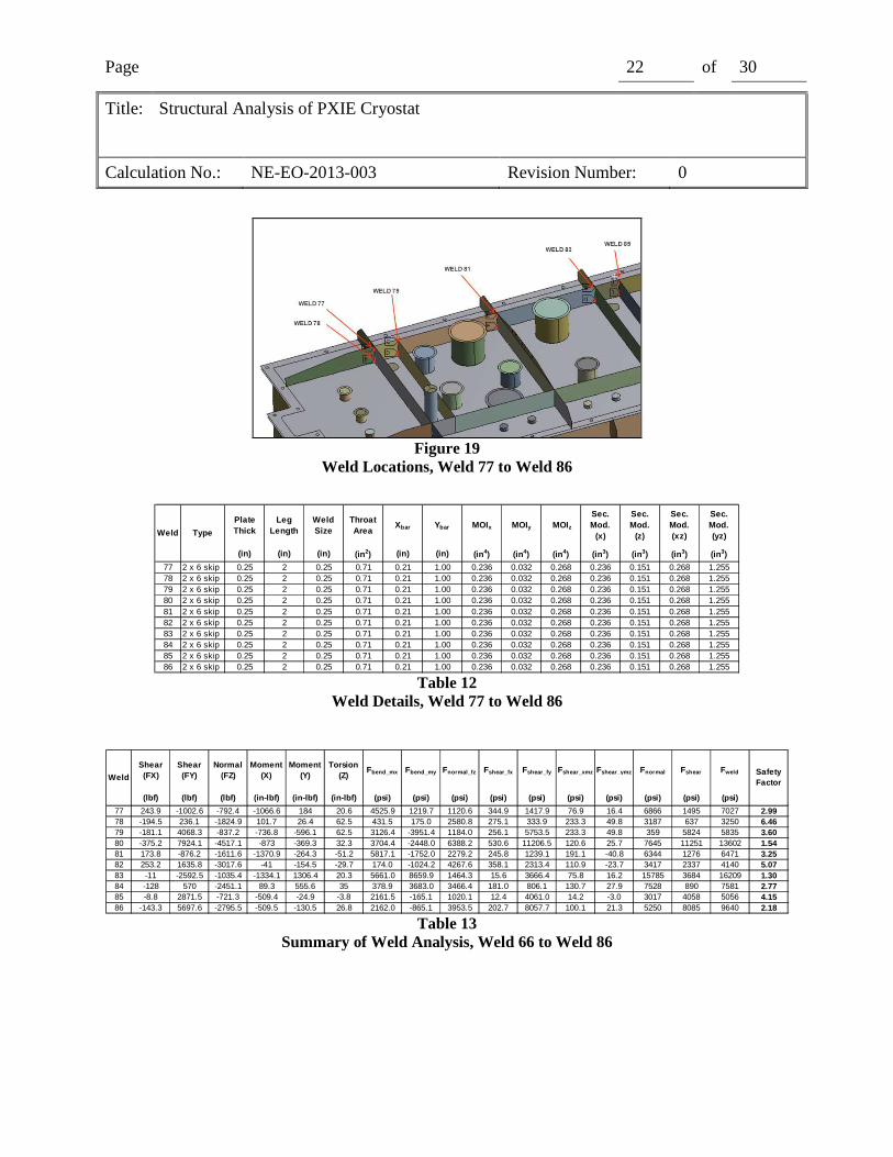
Figure 19
Weld Locations, Weld 77 to Weld 86
Plate Thick
Leg Length
Weld Size
Throat Area
Xbar Ybar MOIx MOIy MOIz
Sec. Mod.
(x)
Sec. Mod.
(z)
Sec. Mod. (xz)
Sec. Mod. (yz)
(in) (in) (in) (in2) (in) (in) (in4) (in4) (in4) (in3) (in3) (in3) (in3)
77 2 x 6 skip 0.25 2 0.25 0.71 0.21 1.00 0.236 0.032 0.268 0.236 0.151 0.268 1.25578 2 x 6 skip 0.25 2 0.25 0.71 0.21 1.00 0.236 0.032 0.268 0.236 0.151 0.268 1.25579 2 x 6 skip 0.25 2 0.25 0.71 0.21 1.00 0.236 0.032 0.268 0.236 0.151 0.268 1.25580 2 x 6 skip 0.25 2 0.25 0.71 0.21 1.00 0.236 0.032 0.268 0.236 0.151 0.268 1.25581 2 x 6 skip 0.25 2 0.25 0.71 0.21 1.00 0.236 0.032 0.268 0.236 0.151 0.268 1.25582 2 x 6 skip 0.25 2 0.25 0.71 0.21 1.00 0.236 0.032 0.268 0.236 0.151 0.268 1.25583 2 x 6 skip 0.25 2 0.25 0.71 0.21 1.00 0.236 0.032 0.268 0.236 0.151 0.268 1.25584 2 x 6 skip 0.25 2 0.25 0.71 0.21 1.00 0.236 0.032 0.268 0.236 0.151 0.268 1.25585 2 x 6 skip 0.25 2 0.25 0.71 0.21 1.00 0.236 0.032 0.268 0.236 0.151 0.268 1.25586 2 x 6 skip 0.25 2 0.25 0.71 0.21 1.00 0.236 0.032 0.268 0.236 0.151 0.268 1.255
Weld Type
Table 12
Weld Details, Weld 77 to Weld 86
Shear (FX)
Shear (FY)
Normal (FZ)
Moment (X)
Moment (Y)
Torsion (Z)
Fbend_mx Fbend_my Fnormal_fz Fshear_fx Fshear_fy Fshear_xmz Fshear_ymz Fnormal Fshear Fweld
(lbf) (lbf) (lbf) (in-lbf) (in-lbf) (in-lbf) (psi) (psi) (psi) (psi) (psi) (psi) (psi) (psi) (psi) (psi)
77 243.9 -1002.6 -792.4 -1066.6 184 20.6 4525.9 1219.7 1120.6 344.9 1417.9 76.9 16.4 6866 1495 7027 2.9978 -194.5 236.1 -1824.9 101.7 26.4 62.5 431.5 175.0 2580.8 275.1 333.9 233.3 49.8 3187 637 3250 6.4679 -181.1 4068.3 -837.2 -736.8 -596.1 62.5 3126.4 -3951.4 1184.0 256.1 5753.5 233.3 49.8 359 5824 5835 3.6080 -375.2 7924.1 -4517.1 -873 -369.3 32.3 3704.4 -2448.0 6388.2 530.6 11206.5 120.6 25.7 7645 11251 13602 1.5481 173.8 -876.2 -1611.6 -1370.9 -264.3 -51.2 5817.1 -1752.0 2279.2 245.8 1239.1 191.1 -40.8 6344 1276 6471 3.2582 253.2 1635.8 -3017.6 -41 -154.5 -29.7 174.0 -1024.2 4267.6 358.1 2313.4 110.9 -23.7 3417 2337 4140 5.0783 -11 -2592.5 -1035.4 -1334.1 1306.4 20.3 5661.0 8659.9 1464.3 15.6 3666.4 75.8 16.2 15785 3684 16209 1.3084 -128 570 -2451.1 89.3 555.6 35 378.9 3683.0 3466.4 181.0 806.1 130.7 27.9 7528 890 7581 2.7785 -8.8 2871.5 -721.3 -509.4 -24.9 -3.8 2161.5 -165.1 1020.1 12.4 4061.0 14.2 -3.0 3017 4058 5056 4.1586 -143.3 5697.6 -2795.5 -509.5 -130.5 26.8 2162.0 -865.1 3953.5 202.7 8057.7 100.1 21.3 5250 8085 9640 2.18
WeldSafety Factor
Table 13
Summary of Weld Analysis, Weld 66 to Weld 86
Page 23 of 30
Title: Structural Analysis of PXIE Cryostat
Calculation No.: NE-EO-2013-003 Revision Number: 0
Figure 20
Weld Locations, Welds 87, 89, 90, 92, 106, 107
Leg Length
Min. Plate Thick
Throat Area
Ybar MOIx Polar MOIz
Sec. Mod.
(x)
Sec. Mod. (z)
(in) (in) (in2) (in) (in4) (in4) (in3) (in3)
87 CJP 36.50 0.38 13.69 18.25 1074 1074 59 5989 CJP 37.00 0.38 13.88 18.50 1119 1119 60 6090 CJP 36.50 0.38 13.69 18.25 1074 1074 59 5992 CJP 37.00 0.38 13.88 18.50 1119 1119 60 60
106 CJP 225.72 0.25 56.43 112.86 169390 169390 1501 1501107 CJP 225.72 0.25 56.43 112.86 169390 169390 1501 1501
DescripionWeld
Table 14
Weld Details, Welds 87, 89, 90, 92, 106, 107
Shear (FX)
Shear (FY)
Normal (FZ)
Moment (X)
Moment (Y)
Torsion (Z)
Fbend_mx Fnormal_fz Fshear_fx Fshear_fy Fshear_xmz Fnormal Fshear
(lbf) (lbf) (lbf) (in-lbf) (in-lbf) (in-lbf) (psi) (psi) (psi) (psi) (psi) (psi) (psi)
87 -10795.7 227.3 -11144.3 3994.9 -35126.7 -5516.5 67.86 814.20 788.73 16.61 93.71 882.06 882.59 12.1689 -8004.3 1805.3 -6750.6 11512.6 -26256.1 -40157.4 190.31 486.53 576.89 130.11 663.84 676.84 1247.53 9.2890 -14215.6 59 -9771 -6057.6 -32304.3 8604.6 102.90 713.86 1038.58 4.31 146.17 816.76 1184.76 9.5892 7871.4 365 -5334.3 -20424.1 19737.1 33859.2 337.63 384.45 567.31 26.31 559.72 722.08 1127.34 10.14
106 5683.2 29.8 -92411.3 603750.4 -3836.5 -34978.2 402.26 1637.63 100.71 0.53 23.31 2039.89 124.02 11.68107 -9996.7 -466.2 -49729.1 -176315 3632 -11077.8 117.47 881.25 177.15 8.26 7.38 998.73 184.72 22.54
Safety Factor
Weld
Table 15
Summary of Weld Analysis, Welds 87, 89, 90, 92, 106, 107
Page 24 of 30
Title: Structural Analysis of PXIE Cryostat
Calculation No.: NE-EO-2013-003 Revision Number: 0
Figure 21
Weld Locations, Welds 88, 92, 93, 94
Table 16
Weld Details, Welds 88, 92, 93, 94
Table 17
Summary of Weld Analysis, Welds 88, 92, 93, 94
Page 25 of 30
Title: Structural Analysis of PXIE Cryostat
Calculation No.: NE-EO-2013-003 Revision Number: 0
Figure 22
Weld Locations, Weld 95 to Weld 105
Dia.Weld Size
Throat Area
Xbar Ybar MOIx MOIy MOIz Sec. Mod.
(x) Sec. Mod.
(z) Sec. Mod.
(xz) Sec. Mod.
(yz)
(in) (in) (in2) (in) (in) (in4) (in4) (in4) (in3) (in3) (in3) (in3)
95 circular tube 3.875 0.125 1.08 1.94 1.94 2.0193 2.0193 4.0386 1.0422 1.0422 2.0845 2.084596 circular tube 3.875 0.125 1.08 1.94 1.94 2.0193 2.0193 4.0386 1.0422 1.0422 2.0845 2.084597 circular tube 3.875 0.125 1.08 1.94 1.94 2.0193 2.0193 4.0386 1.0422 1.0422 2.0845 2.084598 circular tube 3.875 0.125 1.08 1.94 1.94 2.0193 2.0193 4.0386 1.0422 1.0422 2.0845 2.084599 circular tube 3.875 0.125 1.08 1.94 1.94 2.0193 2.0193 4.0386 1.0422 1.0422 2.0845 2.0845
100 circular tube 3.875 0.125 1.08 1.94 1.94 2.0193 2.0193 4.0386 1.0422 1.0422 2.0845 2.0845101 circular tube 9.875 0.125 2.74 4.94 4.94 33.4196 33.4196 66.8391 6.7685 6.7685 13.5370 13.5370102 circular tube 9.875 0.125 2.74 4.94 4.94 33.4196 33.4196 66.8391 6.7685 6.7685 13.5370 13.5370103 circular tube 5.875 0.125 1.63 2.94 2.94 7.0374 7.0374 14.0748 2.3957 2.3957 4.7914 4.7914104 circular tube 7.875 0.125 2.19 3.94 3.94 16.9489 16.9489 33.8978 4.3045 4.3045 8.6090 8.6090105 circular tube 11.875 0.125 3.30 5.94 5.94 58.1153 58.1153 116.2305 9.7878 9.7878 19.5757 19.5757
Weld Type
Table 18
Weld Details, Weld 95 to Weld 105
Shear (FX)
Shear (FY)
Normal (FZ)
Moment (X)
Moment (Y)
Torsion (Z)
Fbend_mx Fbend_my Fnormal_fz Fshear_fx Fshear_fy Fshear_xmz Fshear_ymz Fnormal Fshear Fweld
(lbf) (lbf) (lbf) (in-lbf) (in-lbf) (in-lbf) (psi) (psi) (psi) (psi) (psi) (psi) (psi) (psi) (psi) (psi)
95 0.00 -0.50 -1513.40 -0.10 -0.20 0.00 0.1 -0.2 1406.7 0.0 0.5 0.0 0.0 1406.6 0.5 1406.6 14.9396 0.00 -0.60 -1513.40 0.00 0.10 0.00 0.0 0.1 1406.7 0.0 0.6 0.0 0.0 1406.8 0.6 1406.8 14.9397 0.10 -0.20 -1513.30 0.10 -0.20 0.00 0.1 -0.2 1406.6 0.1 0.2 0.0 0.0 1406.5 0.2 1406.5 14.9398 0.00 -0.90 -1513.40 0.10 0.10 0.00 0.1 0.1 1406.7 0.0 0.8 0.0 0.0 1406.9 0.8 1406.9 14.9399 -0.10 -0.40 -1513.30 -0.10 -0.20 0.00 0.1 -0.2 1406.6 0.1 0.4 0.0 0.0 1406.5 0.4 1406.5 14.93
100 0.00 -0.90 -1513.40 -0.10 0.10 0.00 0.1 0.1 1406.7 0.0 0.8 0.0 0.0 1406.9 0.8 1406.9 14.93101 -0.10 2.10 -1529.30 0.10 0.10 0.00 0.0 0.0 557.8 0.0 0.8 0.0 0.0 557.8 0.8 557.8 37.65102 -0.20 0.70 -1521.80 0.00 -0.10 0.00 0.0 0.0 555.1 0.1 0.3 0.0 0.0 555.0 0.3 555.0 37.83103 -0.30 -0.30 -589.10 -0.40 0.10 0.00 0.2 0.0 361.2 0.2 0.2 0.0 0.0 361.4 0.3 361.4 58.11104 0.00 0.00 -1018.10 0.20 0.10 0.00 0.0 0.0 465.7 0.0 0.0 0.0 0.0 465.7 0.0 465.7 45.09105 0.00 0.00 -1612.90 0.00 0.00 0.00 0.0 0.0 489.2 0.0 0.0 0.0 0.0 489.2 0.0 489.2 42.93
WeldSafety Factor
Table 19
Summary of Weld Analysis, Weld 95 to Weld 105
Page 26 of 30
Title: Structural Analysis of PXIE Cryostat
Calculation No.: NE-EO-2013-003 Revision Number: 0
11. Discussion The goal of this analysis was to confirm compliance with the APSSM and the FESHM, which categorize vacuum systems based on the maximum static differential operating pressure that the system might experience. It was determined that this system qualifies as Category II vessel per the APSSM Mandatory Appendix M, which includes vacuum vessels “that can be protected from pressurization exceeding 15 psi through such engineering controls as pressure relief devices.” This vacuum system is so protected. CGA 341 (Ref. 8) states in section 6.4.2 that vacuum vessels must be relieved with devices of discharge area “at least 0.00024 in2 per pound of water capacity of the liquid container.” The LHe volume of the eight HWRs, eight magnet packages, LHe manifold, and LHe manifold lines is < 20 ft3 amounting to < 1250 lb of water equivalent. This results in a required relief area of 0.3 in2. The vacuum vessel is relieved via two spring-loaded ISO-80 flanges each with 3.5” bore and 1” of travel, each provides a relief area of 11 in2, well in excess of this requirement ensuring that the interior pressure of the vacuum vessel will never exceed atmospheric pressure (14.7 psia).
Per Ref. 1, Category II vacuum systems are not required to comply with the ASME pressure vessel code, but states that “vacuum vessels may be designed in accordance with the applicable sections of the ASME Code.” The intent was to utilize finite element analysis to check this design, so the provisions of Section VIII, Division 2, covering Design by Analysis, were used to guide this analysis.
The assumption of steady loads seems justified by Ref.3. Using Method A for Fatigue Analysis Screening(5.5.2.3, Ref 2), the total number of full or partial pressure cycles, and the total number of temperature cycles with full or partial pressure was estimated to be no more than 80. This is less than any of the limiting criteria given in Ref. 3 Table 5-9. If this estimate is valid, then fatigue is not an issue. The last assumptions must be judged on their own merits. The assumption of room temperature operation is based on the fact that the cryostat contains a vacuum that insulates the equipment inside, and that thermal leak paths are limited. The assumption of no material degradation over time seems reasonable considering the room temperature operation and the laboratory environment. The assumptions of isotropic and homogeneous response and no residual stress are common engineering assumptions.
12. Conclusions The results of this analysis presented above show that the requirements for Protection Against Plastic Collapse, Protection Against Local Failure, Protection Against Collapse From Buckling, Protection From Ratcheting, Protection Against Failure from Cyclic Loading, per the ASME BPVC, have been met for the loading conditions. Also, all welds meet the requirements of AWS D1.6. Based on this, the following conclusions are drawn:
1. The PXIE Cryostat is in compliance with the Fermi National Accelerator Laboratory Environmental Safety and Health Manual when subjected to an internal vacuum load not to exceed 15 psi as described in this analysis.
Page 27 of 30
Title: Structural Analysis of PXIE Cryostat
Calculation No.: NE-EO-2013-003 Revision Number: 0
13. References 1. Argonne Pressure Systems Safety Manual, Argonne National Laboratory, Lemont, IL,
2012.
2. Fermilab Environment, Safety and Health Manual, Fermi National Accelerator Laboratory, Batavia, IL, 2013
3. ASME Boiler and Pressure Vessel Code, Section VIII, Division 2, Part 5, American Society of Mechanical Engineers, New York, NY 2010.
4. ASME Electronic Stress Tables, Table 1A, page 18, Line 874, www.est.asme.org/knovel2/asme,
5. Metallic Materials Properties Development and Standardization, DOT/FAA/AR-MMPDS-01, Office of Aviation Research, Washington DC, 2003.
6. Shigley, J. E. and Mitchell, L. D. Mechanical Engineering Design, Fourth Edition, McGraw Hill, New York, 1983, Chapter 7.
7. Structural Welding Code - Stainless Steel, AWS D1.6:1999, American Welding Society, Doral, FL, 1999.
8. Standard for Insulated Cargo Tank Specification for Nonflammable Cryogenic Liquids, CGA-341, Compressed Gas Association, 1995.
14. Software
• Ansys Mechanical, Version 13, Build date 11/2/2009, Ansys Inc, Pittsburg, PA.
• Microsoft Windows XP Professional x64, Version 2003, Service Pack 2, Microsoft Corporation, Redmond WA.
• Microsoft Office Excel 2007, (12.0.6654,5003) SP3 MSO (12.0.6607.1000), Microsoft Corporation, Redmond WA.

Page 28 of 30
Title: Structural Analysis of PXIE Cryostat
Calculation No.: NE-EO-2013-003 Revision Number: 0
APPENDIX 1 GENERAL CHECKING CRITERIA SHEET
ANALYSIS CHECKLIST Yes No N/A Comments
Are analytical methods appropriate?
Are assumptions appropriate?
Is the analysis complete?
Is the source of the input geometry documented?
Is the source of material properties documented?
Are the boundary conditions clearly explained?
Was an applicable and valid computer program used?
Are the conclusions supported by the results?
Do the results seem reasonable?
Page 29 of 30
Title: Structural Analysis of PXIE Cryostat
Calculation No.: NE-EO-2013-003 Revision Number: 0
Copyright © 2022 FDOKUMEN