NB 5 / NB 9 / NB 20 USER'S MANUAL - Frederiksen Scientific
21
NÜVE SANAYİ MALZEMELERİ İMALAT VE TİCARET A.Ş. NB 5 / NB 9 / NB 20 WATER BATHS USER’S MANUAL Z14.K 25 255 Rev. No: 11 Rev. Date: 07/2017
-
Upload
khangminh22 -
Category
Documents
-
view
0 -
download
0
Transcript of NB 5 / NB 9 / NB 20 USER'S MANUAL - Frederiksen Scientific

NÜVE SANAYİ MALZEMELERİ İMALAT VE TİCARET A.Ş.
NB 5 / NB 9 / NB 20
WATER BATHS
USER’S MANUAL
Z14.K 25 255 Rev. No: 11 Rev. Date: 07/2017

2
Dear Nüve User,
We would like to take this opportunity to thank you for preferring this Nüve product. Please read the operating instructions carefully and keep them handy for future reference.
Please detain the packing material until you see that the unit is in good condition and it is operating properly. If an external or internal damage is observed, contact the transportation company immediately and report the damage. According to ICC regulations, this responsibility belongs to the customer.
While you are operating the instrument please;
1. obey all warning labels,
2. do not remove warning labels,
3. do not operate damaged instrument,
4. do not operate instrument with a damaged cable,
5. do not move instrument during operation.
In case of a problem contact your Nüve agent for an authorized service or maintenance.
The validity of the guarantee is subject to compliance with the instructions and precautions described in this manual.
Nüve reserves the right to improve or change the design of its products without any obligation to modify previously manufactured products.
Information contained in this document is the property of Nüve. It may not be duplicated or distributed without our permission.
Lifetime of the device is 10 years.
NÜVE SANAYİ MALZEMELERİ İMALAT VE TİCARET A.Ş.
Saracalar Mah. Saracalar Kümeevleri No: 4/2 Akyurt 06750 Ankara / TURKEY Tel : (90.312) 399 28 30 (pbx) Fax : (90.312) 399 21 97 Sales : [email protected] Technical Service: [email protected]

3
WARRANTY CERTIFICATE
1. Nüve warrants that the equipment delivered is free from defects in material and workmanship. This warranty is given for a period of two years. The warranty period begins from the delivery date.
2. Warranty does not apply to parts normally consumed during operation or general maintenance or any adjustments described in the operating instructions provided with the instrument.
3. Nüve does not accept any liability in case where the goods are not used in accordance with their proper intent.
4. The warranty may not be claimed for damages incurred during the shipment, for damages resulting from improper handling or use, abuse, fire, liquid spillage, tampering or unauthorized repairs by any persons, use of defective or incompatible accessories, exposure to abnormally corrosive conditions, use of the product in non-standard environmental conditions, including but not limited to failure to meet requirements of ambient temperature, lubrication, humidity or magnetic field influences, from the defects in maintenance, negligence, bad functioning of auxiliary equipment, in the case of force majeure or accident and incorrect power supply.
5. Any injury, loss or damage caused; due to a failure resulting from negligence of the instructions given in this manual; is beyond the scope of the warranty conditions.
BEFORE OPERATING THE INSTRUMENT THIS MANUAL SHOULD BE READ CAREFULLY.
THE VALIDITY OF THE GUARANTEE IS SUBJECT TO THE OBSERVATION OF THE INSTRUCTIONS AND PRECAUTIONS DESCRIBED IN THIS MANUAL.
INFORMATION CONTAINED IN THIS DOCUMENT IS THE PROPERTY OF NÜVE. IT MAY NOT BE DUPLICATED OR DISTRIBUTED WITHOUT PERMISSION.
PLEASE REGISTER ONLINE TO VALIDATE YOUR WARRANTY:
To register your warranty online, please visit our webpage www.nuve.com.tr and fill in the “Warranty Registration Form”.

4
CONTENT Page
CONTENT ……………………………………………………………………………………………………………………………………………….. 4
1. INTRODUCTION ……………………………………………………………………………………………………………………………… 5
1.1 USE AND FUNCTION ……………………………………………………………………………………………………………….. 5
2. TECHNICAL SPECIFICATIONS ………………………………………………………………………………………………………….. 6
2.1 TECHNICAL SPECIFICATIONS TABLE ………………………………………………………………………………………… 6
2.2 OPTIONAL ACCESSORIES ………………………………………………………………………………………………………… 6
3. PRECAUTIONS AND LIMITATIONS ON USE …………………………………………………………………………………….. 7
4. SYMBOLS AND LABELS ………………………………………………………………………………………………………………….. 7
5. INSTALLATION ……………………………………………………………………………………………………………………………….. 8
5.1 ENVIRONMENTAL CONDITIONS ……………………………………………………………………………………………… 8
5.2 HANDLING AND TRANSPORTATION ………………………………………………………………………………………… 8
5.3 UNPACKING …………………………………………………………………………………………………………………………… 8
5.4 MAINS SUPPLY ……………………………………………………………………………………………………………………….. 8
5.5 POSITIONING ………………………………………………………………………………………………………………………….. 8
5.6 GENERAL PRESENTATION ……………………………………………………………………………………………………….. 9
5.7 CONTROL PANEL ………………………………………………………………………………………………………………….. 10
5.7.1 Explanations and Functions for Display and Control Panel ……………………………………………. 10
5.8 PRIOR TO OPERATION …………………………………………………………………………………………………………… 11
5.8.1 FILLING THE TANK …………………………………………………………………………………………………………. 12
6. OPERATING PRINCIPLES ………………………………………………………………………………………………………………. 12
6.1 PREPARATION OF USER SETTINGS ……………………………………………………………………………………….. 12
6.1.1 oP Operator Menu Parameters …………………………………………………………………………………….. 13
6.2 PROGRAMMING SUMMARY …………………………………………………………………………………………………. 14
6.3 COMPLETION OF OPERATION ……………………………………………………………………………………………….. 17
7. PERIODIC MAINTENANCE AND CLEANING ……………………………………………………………………………………. 18
7.1 PERIODIC MAINTENANCE ……………………………………………………………………………………………………… 18
7.2 CLEANING …………………………………………………………………………………………………………………………….. 18
8. DISPOSAL MANAGEMENT CONCEPT ……………………………………………………………………………………………. 18
9. TROUBLESHOOTING …………………………………………………………………………………………………………………… 18
9.1 ERROR CODES EXPLANATIONS ……………………………………………………………………………………………… 19
9.2 FUSE REPLACEMENT ……………………………………………………………………………………………………………… 20
10. ELECTRICAL CIRCUIT DIAGRAM …………………………………………………………………………………………………. 21
10.1 NB 5 / NB 9 / NB 20 ELECTRICAL CIRCUIT DIAGRAM …………………………………………………………. 21

5
1. INTRODUCTION 1.1 USE AND FUNCTION NB 5, NB 9 and NB 20 Water Baths accurately control the temperatures of samples and commonly used in microbiology, research and industrial laboratories. They offer excellent temperature control of liquid producing a uniform and stable heating environment for the applications. They provide temperatures between 5°C above the ambient temperature and 99.9°C for procedures where temperature uniformity and stability are important. The homogeneous temperature distribution in the tank is ensured by means of the heaters which are placed around chamber.
The baths are equipped with the timer and they are controlled by a PID microprocessor controlled system to ensure precise temperature control. Two digital displays situated on the user-friendly control panel display the temperature and time values.
Microprocessor control system will shut down the temperature sensor and in case of malfunctions that may occur in the control system, alarm system will be activated and the user is warned visually and audibly. The study data are recorded in the memory and can be transferred to external USB memory. At the same time, unauthorized persons have been blocked permission to change parameters with improved password menu.
All components which are exposed to liquid are made of high grade stainless steel to resist corrosion.
The NB Series Water Baths are manufactured according to the following standards: EN 61010-1, EN 61326-1, EN 50419. This device is in compliance with WEEE Regulation.
If the warnings mentioned in this manual are not considered, NUVE will not be responsible from their results.

6
2. TECHNICAL SPECIFICATIONS
2.1 TECHNICAL SPECIFICATIONS TABLE
TECHNICAL SPECIFICATIONS NB 5 NB 9 NB 20
Temperature Range Ambient temperature + 5°C / 99.9°C
Temperature Sensor Fe–Const.
Control System N-PrimeTM
Temperature Set and Display Sensitivity
0.1°C
Temperature Uniformity (<40°C) ± 0.2°C
Temperature Fluctuation ± 0.1°C
Timer 1 min – 99.9 hours + Hold position
Delayed Start Timer 1 min – 99.9 hours
Memory 3000 data*
Power Supply 230 V, 50 / 60 Hz
Power Consumption 600 W 800 W 1600 W
Tank Volume (Liters) 6 9.5 21
Useful Volume (Liters) 4 7 15
Internal Material Stainless Steel
External Material Epoxy-Polyester Coated Steel
Internal Dimensions (WxDxH) (mm) 150x300x150 240x300x150 500x300x150
External Dimensions (WxDxH) (mm) 240x400x275 325x400x275 595x400x275
Net / Packed Weight (kg) 7 / 8 8 / 9 11 / 13 * Shows the number of lines for each work done. Temperature, time and if there is error code consist of 1 line.
2.2 OPTIONAL ACCESSORIES K 04 290 Plexiglass lid for NB 5 (resists up to 60°C) K 52 010 Stainless steel lid for NB 5 K 04 286 Plexiglass lid for NB 9 (resists up to 60°C) K 52 007 Stainless steel lid for NB 9 K 04 289 Plexiglass lid for NB 20 (resists up to 60°C) K 52 003 Stainless steel lid for NB 20 K 52 008 Lid with 4 holes for NB 9 (Hole dia 95 mm) K 52 005 Lid with 4 holes for NB 20 (Hole dia 95 mm) K 52 006 Lid with 6 holes for NB 9 (Hole dia 95 mm) K 52 014 Lid with 8 holes for NB 9 (Hole dia 95 mm) A 08 051 Tube rack 52xØ13 mm, wide 70 mm A 08 050 Tube rack 30xØ16 mm, wide 70 mm A 08 021 Tube rack 27xØ18 mm, wide 70 mm A 08 049 Tube rack 12xØ30 mm, wide 70 mm

7
3. PRECAUTIONS AND LIMITATIONS ON USE
The user shall pay attention to the following:
Do not operate the instrument for purposes other than its main purpose.
The instrument should only be used by authorized and trained staff after the instruction manual has been read carefully. Only authorized technical staff can handle the product in case of a failure.
Only original spare parts and original accessories supplied by Nüve should be used.
Electricity line is suitable for the power of device and correctly grounded power supply should be used.
The set temperature should not destroy the structure of the samples without user’s notice.
The boiling points of the samples should be higher than the set temperature.
The samples which may liquefy and expand should not be in a sealed container.
Liquids which may expand during heating should not overflow from their containers.
The materials which will be subject to heating should not be combustible, explosive, heat susceptible, flammable, adhesive and fusible.
Ensure that the vapors and gases generated during the operation are not harmful to human health and flammable or explosive.
4. SYMBOLS AND LABELS
Symbol in the operating instructions:
Attention, general hazard area.
This symbol refers to safety relevant warnings and indicates possibly dangerous situations.
The non-adherence to these warnings can lead to material damage and injury to personal.
Symbol in the operating instructions:
This symbol refers to important circumstances.
Labels on the product:

8
NB 5 Fuse (2x4A) NB 9 Fuse (2x5A) NB 20 Fuse (2x10A)
Earthed Wall Sockets
5. INSTALLATION 5.1 ENVIRONMENTAL CONDITIONS The instrument is designed to operate safely under the following conditions:
Indoor use only
Ambient temperature: 5°C to 40°C
Maximum relative humidity for temperature up to 31°C: 80%
Maximum altitude: 2000 m
Temperature for maximum performance: 15°C / 25°C
5.2 HANDLING AND TRANSPORTATION All handling and transportation must be carried out by using proper equipment and experienced staff. The instrument must be supported underneath and never be turned upside down. 5.3 UNPACKING Remove the cardboard box packing and the second nylon wrapping around the instrument. Ensure that no damage has occurred during transportation. The below mentioned are provided with the instrument, please check them;
1 ea. user’s manual and warranty
1 ea. electrical cable
1 ea. perforated grid
5.4 MAINS SUPPLY The instrument requires 230 V, 50 / 60 Hz.
Please make sure that the supplied mains matches the required power ratings which are written on the name of plate of the instrument located at the back of the instrument.
Always plug-in the instrument to correctly grounded sockets.
A supply fitted with a circuit breaker should be used for protection against indirect contact in case of isolation fault.
5.5 POSITIONING
Check that the positioning is suitable for the users.
Check that the instrument is stable on its four pedestals.
Check that the user will be able to follow up the operation even when he deals with something else.

9
Check that the positioning of the device prevents interference with other equipment in the near surrounding.
5.6 GENERAL PRESENTATION
Figure 1
Figure 2
Figure 3
DISPLAY AND CONTROL PANEL
SUPPLY INPUT AND FUSES
WATER DISCHARGE LINE
INPUT USB
ON/OFF SWİTCH
TANK
TEMPERATURE SENSOR
GRID

10
5.7 CONTROL PANEL
Figure 4
1. Temperature display 6. “Operating the program” lamp 11. Back / Alarm mute button
2. Time display 7. Data transfer lamp
3. Encoder button 8. Alarm led
4. Start / Stop button 9. “End of the program” lamp
5. Heating lamp 10. Usb lamp
5.7.1 Explanations and Functions for Display and Control Panel
01-Temperature Display
This display shows
Sterilization chamber temperature during “stand-by” and during the operation (thermometer position),
During program preparation, the temperature setting values or the alarm setting values,
Failure codes,
EoF warning when power is interrupted,
The set temperature values and alarm values.
02-Time Display
This display shows the values set for time during program preparation. Also; this display shows he time values in the control of the settings.
10
11
03-Encoder Button
The encoder button has two physical movements. The button turn clockwise and anticlockwise to increase or decrease the temperature and time values of the program. Also, the button press for select / confirm.
04-Start / Stop Button
Used button to start the device to operating at set values or to stop the operation.
05-Heating Lamp
The led is “on” during heating, it indicates that the heating process is carried out.
06-“Operating The Program” Lamp
A lamp indicating that the program is running as soon as the device is started.
07-Data Transfer Lamp
The lamp indicates that the records are transferred in the memory or the file is transferred during software update.
08-Alarm Led
This led flashes when there is a warning or error on the device.
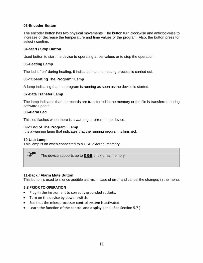
09-“End of The Program” Lamp It is a warning lamp that indicates that the running program is finished. 10-Usb Lamp This lamp is on when connected to a USB external memory.
The device supports up to 8 GB of external memory.
11-Back / Alarm Mute Button This button is used to silence audible alarms in case of error and cancel the changes in the menu.
5.8 PRIOR TO OPERATION
Plug-in the instrument to correctly grounded sockets.
Turn on the device by power switch.
See that the microprocessor control system is activated.
Learn the function of the control and display panel (See Section 5.7 ).

12
5.8.1 FILLING THE TANK
Fill the tank with distilled water or liquid up to the maximum line MAX (see Figure 5). Undesired problems may occur if you fill up to the level lower than the max level.
Figure 5
Make sure that the filled liquid is not flammable or explosive at the operation temperature.
Do not run the device unless distilled water or liquid is fılled up to max line.
Add distilled water if the level drops below the “MAX” line during the operation
6. OPERATING PRINCIPLES
6.1 PREPARATION OF USER SETTINGS
The device has a password protected menu. The password is set to “000” when the device first starts. Follow the below steps to change the password, update current date / time information and access the operator's menu where other settings are made.
MAX. Line

13
Wait by pressing the encoder button.
Lift your hand when you see "oP" on the temperature display and again press the encoder button. If the device has a menu protection password, password screen “oPS” will come on the temperature display.
You enter the set password to turn the encoder button right and left. ( The password will not be asked if the device is newly installed.) Confirm the password by pressing the encoder button. Observe that the parameter numbers on the temperature display change with each pressing the encoder button. For operator menu parameter descriptions (see section 6.1.1). You can set the parameter values by turning the encoder button right or left on time display.
Again press the encoder button and confirm the set value. Press the back button to return the work screen.
6.1.1 oP Operator Menu Parameters
1: Recording Period: This time is recording period of temperature and error information.
2: Lid Alarm Time: Not used for all NB models.
3: Lid Alarm Range: Not used for all NB models.
4: Timer Set Band: When the read temperature reaches the "Set Temperature - TIMER SET BAND" value, the time starts counting backwards.
5: Buzzer ON/OFF: The alarm sound on/off 0: OFF 1: ON
6: Date Setting - Year: Two digits are displayed the year information of date. If updating is necessary, change.

14
7: Date Setting - Month: The month information of date is displayed. If updating is necessary, change.
8: Date Setting - Day: The day information of date is displayed. If updating is necessary, change.
9: Time Setting - Hour: The hour information of time is displayed. If updating is necessary, change.
A: Time Setting - Minute: The minute information of time is displayed. If updating is necessary, change.
B: Time Setting – Second: The second information of time is displayed. If updating is necessary, change.
C: Date / Time Update: 0: No change 1: Update date / time according to the entered values. The entered values are considered as current Date / Time information when 5, 6, 7, 8, 9, A parameters are changed and B parameter is set to 1.
D: Password: The password used to enter the operator parameters. This password used when you want to change the set values. No password if 0 is selected.
6.2 PROGRAMMING SUMMARY
You can set the steam sterilizer on stand-by. Follow the below steps to set and save the values.
Push the encoder button
By pushing the encoder button select SET menu.
See that second LED flashes in the temperature display, again push the encoder button.

15
See the parameter flashing on the temperature display.
By turning the encoder button set operating temperature value.
Push the encoder button and save set value.
See the parameter flashing on the temperature display.
By turning the encoder button set operating Set alarm value. If the temperature is out of Set alarm value, audible and visual alarm will be activated.
Push the encoder button and save set value.
Turn the encoder button to the right.

16
See that second LED flashes in the time display, again push the encoder button.
See the parameter flashing on the time display.
By turning the encoder button set operating time value (01 minute to 99 hours 54 minutes or Hold).
Push the encoder button and save set value. See 'dLY' in the temperature display.
By turning the encoder button set operating delay time value. If 'Off' is selected, heating will start without delay. If any numerical value is selected; After pressing Start, it starts heating after the set delay time (01 minute to 99 hours 54 minutes).
.
Push the encoder button and save set value.
Push ‘the start button’ and start the program.

17
In order to display the set values during the operation, push the encoder button once. The values set on the temperature display and the time display of the device will appear for 5 seconds.
During the operation of the program, the time starts to count up after the instrument has reached to the set temperature
6.3 COMPLETION OF OPERATION
Ensure that the program is over (See “End” and “End of the program lamp”).
Take the samples out at the end of the operation.
Take precautions while handling the samples after the operation as they can be hot.
Remove the undesirable effects occurred during the operation after the tank has been completely emptied.
You may leave the bath at stand-by or switch it off.
Operating records are transferred to the usb port attached a USB memory.
Check the liquid level in the tank during long operations and refill to the max line if necessary.
The usb led and the data transfer led on the control panel turn on during transfer of data in memory and the transfer process starts automatically. Do not remove external memory from usb port without the data transfer led turn off and the audible alarm finished.
Records are transferred to external memory when external memory is connected to the Usb port.

18
7. PERIODIC MAINTENANCE AND CLEANING 7.1 PERIODIC MAINTENANCE The instrument does not require any periodical maintenance. 7.2 CLEANING
Clean the device when the chamber is at room temperature after disconnecting the power cable.
Clean the device with a damp cloth to remove dirt and dust.
Use liquid detergent to remove tough dirt.
Take precautions while handling chemical cleaners. Please be aware of the undesirable effects of the chemicals and be careful while applying them.
Check the external condition of the device regularly and ensure any rust spots that may develop are removed.
8. DISPOSAL MANAGEMENT CONCEPT The currently valid local regulations governing disposal must be observed. It is in the responsibility of the user to arrange proper disposal of the individual components. All parts which may comprise potentially infectious materials have to be disinfected by suitable validated procedures (autoclaving, chemical treatment) prior to disposal. Applicable local regulations for disposal have to be carefully observed. The instruments and electronic accessories (without batteries, power packs etc.) must be disposed off according to the regulations for the disposal of electronic components. Batteries, power packs and similar power source have to be dismounted from electric/electronic parts and disposed off in accordance with applicable local regulations.
9. TROUBLESHOOTING If the device fails to operate, please check the followings:
The power switch is on;
The fuse is not blown;
The plug is plugged-in properly;
The plug is not defective;
The mains supply is present.

19
9.1 ERROR CODES EXPLANATIONS
Er1
The temperature sensor endings are broken. The error code flashes on the temperature display and an audible alarm sounds.
Er2
An electronic failure occurs in the microprocessor. The error code flashes on the temperature display and an audible alarm sounds.
Er3
The temperature sensor measures a temperature higher than 147°C.The error code is shown on the temperature display and an audible alarm sounds.
Er4
The temperature sensor endings are connected in reverse. The error code flashes on the temperature display and an audible alarm sounds.
EoF
This error code appears if any probable power cut causes when the sterilization phase “EoF” flashes and the audible alarm sounds on the temperature display.
IN CASE OF ANY ERROR, THE PROGRAM İS STOPPED AUTOMATİCALLY AND IMMEDIATELY.
If an error occurs, please contact with an authorized Nüve agent to seek technical help.

20
9.2 FUSE REPLACEMENT The fuses shall always be replaced by the authorized personnel.

21
10. ELECTRICAL CIRCUIT DIAGRAM
10.1 NB 5 / NB 9 / NB 20 ELECTRICAL CIRCUIT DIAGRAM