N05616_ver1.7 Multidrop Combi User Manual.pdf
119
Thermo Scientific Multidrop Combi User Manual Rev. 1.7, Cat. no. N05616
-
Upload
khangminh22 -
Category
Documents
-
view
2 -
download
0
Transcript of N05616_ver1.7 Multidrop Combi User Manual.pdf

Thermo Scientific Multidrop Combi User Manual
Rev. 1.7, Cat. no. N05616
Copyright Copyright 2019 Thermo Fisher Scientific Inc. All rights reserved. First edition published in 2005. Reproduction of the accompanying user documentation in whole or in part is prohibited. Trademarks “FILLit” is a trademark and “Microtiter”, “Multidrop” and “Nunc” are registered trademarks of Thermo Fisher Inc. and its subsidiaries. “Decon” is a registered trademark of Decon Laboratories Limited. “Excel” and “Microsoft” are registered trademarks of Microsoft Corporation in the United States and other countries. “Fluka” and “Tween” are trademarks of Sigma-Aldrich GmbH, registered in the US and other countries. “Microside SQ” is a registered trademark of Global Biotechnologies, Inc. “Virkon” is a registered trademark of E.I. du Pont de Nemours and Company or its affiliates. All other trademarks and registered trademarks are the property of their respective holders. Disclaimer Thermo Fisher Scientific reserves the right to change its products and services at any time to incorporate technological developments. This manual is subject to change without prior notice as part of continuous product development. Although this manual has been prepared with every precaution to ensure accuracy, Thermo Fisher Scientific assumes no liability for any errors or omissions, nor for any damages resulting from the application or use of this information. This manual supersedes all previous editions. Remarks on screenshots The version number displayed in screenshots may not always be the one of the currently released version. Screenshots are only replaced if the content related to the application has changed. No liability for consequential damages Thermo Fisher Scientific shall not be liable for any indirect or consequential damages whatsoever arising out of the use or inability to use this product. Power failure The system requires uninterrupted power supply in order to operate correctly. Thermo Fisher Scientific has no responsibility whatsoever for system malfunctions arising from power failures. Manufacturer Life Technologies Holdings Pte. Ltd. (a part of Thermo Fisher Scientific Inc.) 33, Marsiling Industrial Estate Road 3, #7-06, Singapore 739256

Thermo Fisher Scientific Thermo Scientific Multidrop Combi User Manual 3
About This User Manual
This user manual is written for the actual end user (for example, laboratory technician) and provides information on the Thermo Scientific Multidrop Combi, including the installation and operating instructions.
This user manual is designed to give you the information to:
l Review safety precautions
l Setup the Multidrop Combi
l Use the Multidrop Combi internal software
l Carry out dispensing procedures
l Perform basic cleaning and maintenance procedures
l Troubleshoot the instrument performance
This user manual also describes all the features and specifications of the Multidrop Combi instrument as well as ordering information.
Read the manual in its entirety before operating the instrument.
Keep the user manual for future reference. The user manual is an important part of the instrument and should be readily available.
For PC software-related issues, refer to the Thermo Scientific FILLit Software for Multidrop Combi User Manual (Cat. no. N017561).
For the latest information on products and services, visit our websites at:
http://www.thermoscientific.com http://www.thermoscientific.com/multidrop
In our efforts to provide useful and appropriate documentation, we would appreciate any comments you may have on this user manual to your local Thermo Fisher Scientific representative.
Intended users
How to use this user manual
For more information

About This User Manual Safety symbols and markings
4 Thermo Scientific Multidrop Combi User Manual Thermo Fisher Scientific
These symbols are intended to draw your attention to particularly important information and alert you to the presence of hazards as indicated.
The following symbols and markings appear on the type label and the instrument itself.
Power ON s
Power OFF s
Serial number s
Catalog number s
Date of manufacture s
Consult instructions for use s
WEEE symbol This product is required to comply with the European Union’s Waste Electrical & Electronic Equipment (WEEE) Directive 2012/19/EU. s
Safety symbols and markings
Safety symbols and markings used on
the Multidrop Combi
About This User Manual Safety symbols and markings
Thermo Fisher Scientific Thermo Scientific Multidrop Combi User Manual 5
The following symbols and markings appear in this user manual.
Warning Risk of electric shock. s
Warning Biohazard risk. s
Warning Risk of injury to the user(s). s
Caution Risk of damage to the instrument, other equipment or loss of performance or function in a specific application. s
Note Marks a hint, important information that is useful in the optimum operation of the system, or an item of interest. s
Warning and other markings used in
the documentation
About This User Manual Instrument safety and guidelines for use
6 Thermo Scientific Multidrop Combi User Manual Thermo Fisher Scientific
l Always follow basic safety precautions when using the Multidrop Combi to reduce the risk of injury, biohazardous contamination, fire, or electrical shock.
l Read this user manual in its entirety prior to operating the instrument. Failure to read, understand, and follow the instructions in the manual may result in damage to the instrument, injury to laboratory and operating personnel or poor instrument performance.
l Observe all “Warning”, “Caution”, and “Note” statements as well as safety symbols and markings on the instrument and in the documentation.
l The Multidrop Combi is intended for laboratory research use only. Observe proper laboratory safety precautions, such as wearing protective clothing and following approved laboratory safety procedures.
l Use of the Multidrop Combi in ways other than those described in the documentation supplied with the equipment may result in injury to persons or damage to the property. Avoid unintended use of the equipment, for example, using incompatible materials, making unauthorized modifications, using incompatible or damaged parts, using unapproved auxiliary equipment or accessories, or operating equipment in excess of maximum ratings.
l Preventative maintenance instructions should be followed closely to keep the instrument in the best condition for maximum reliability. A poorly maintained instrument will not give the best results.
Instrument safety and guidelines
for use

Thermo Fisher Scientific Thermo Scientific Multidrop Combi User Manual 7
Contents Intended users ................................................................................... 3 How to use this user manual ............................................................. 3 For more information ....................................................................... 3 Safety symbols and markings ............................................................. 4
Safety symbols and markings used on the Multidrop Combi .......... 4 Warning and other markings used in the documentation ............... 5
Instrument safety and guidelines for use ............................................ 6
Introduction to the Multidrop® Combi ..................................................... 13 Intended use .................................................................................... 13 Principle of operation ...................................................................... 13 Advantages of using Multidrop Combi............................................ 15
Functional Description ............................................................................... 16 Instrument layout............................................................................ 16
Front view .................................................................................... 16 Back view ..................................................................................... 17
Installation .................................................................................................... 18 Delivery check ................................................................................. 18
Checking delivery ......................................................................... 18 Unpacking ................................................................................... 18
Requirements .................................................................................. 19 Precautions and limitations ............................................................. 19 Installation setups ............................................................................ 20
Releasing the transport lock .......................................................... 20 Fastening the transport lock ......................................................... 21
Operational check ........................................................................... 22
Routine Operation ........................................................................................ 23 Priming vessel ................................................................................. 23 Dispensing cassettes ........................................................................ 23
Installing the cassette .................................................................... 25 Control panel .................................................................................. 30
Keyboard ...................................................................................... 30 Keys .......................................................................................... 30
Display ......................................................................................... 31 Navigating ................................................................................... 32
Dispensing ...................................................................................... 34 Three key selections to start dispensing ........................................ 35
Using internal software .................................................................... 36 Dispensing parameters .................................................................... 36
Plate type ..................................................................................... 36
Chapter 1
Chapter 2
Chapter 3
Chapter 4

Contents
8 Thermo Scientific Multidrop Combi User Manual Thermo Fisher Scientific
Dispensing cassette and volume.................................................... 38 Column selection ......................................................................... 39
Protocol settings .............................................................................. 42 Dispensing speed .......................................................................... 42 Dispensing offset .......................................................................... 43 Dispensing height ........................................................................ 44 Predispensing volume ................................................................... 45 Dispensing direction .................................................................... 46
Running a protocol ......................................................................... 48 Save and edit protocol .................................................................. 49 Select protocol .............................................................................. 52 Delete protocol ............................................................................ 52
Instrument options .......................................................................... 54 Computer interface ...................................................................... 54 Remote mode ............................................................................... 55 Start-up protocol .......................................................................... 55 Buzzer .......................................................................................... 57
Accept/Save symbol ................................................................... 57 Cassette calibration ...................................................................... 58
Dispensing cassette with SMART option .................................. 59 Screen saver ..................................................................................... 60 Shutdown........................................................................................ 60 Emergency situations ...................................................................... 61
Maintenance ................................................................................................. 62 A) Instrument maintenance ............................................................. 62
Regular and preventive maintenance ............................................ 62 Disposal of materials ....................................................................... 63 Decontamination procedure ............................................................ 63 Packing for service ........................................................................... 65 Service contracts .............................................................................. 65 Disposal of the instrument .............................................................. 66 B) Dispensing cassette maintenance ................................................ 66
Washing the dispensing cassette ................................................... 66 Cleaning the tips .......................................................................... 67 Cleaning the metal tips................................................................. 67 Autoclaving the dispensing cassette .............................................. 68
Changing the tubing set .................................................................. 69 Changing the tip band ................................................................. 69 Fitting the new tubing set step by step ......................................... 70
Disposal of the dispensing cassette................................................... 77
Calibration of the Dispensing Cassette ................................................... 78 Verifying and recalibrating the dispensing cassette .......................... 78
Accuracy verification (gravimetric) ............................................... 78 Materials and equipment needed for accuracy verification ......... 78 Accuracy verification procedure ................................................. 79 Accuracy verification worksheet................................................. 80
Precision verification (photometric) ............................................. 82
Chapter 5
Chapter 6
Contents
Thermo Fisher Scientific Thermo Scientific Multidrop Combi User Manual 9
Materials and equipment required for precision verification ...... 82 Precision verification procedure ................................................. 82
Calibration (gravimetric) .............................................................. 84 Material and equipment required for calibration ....................... 84 Calibration procedure ............................................................... 84
Technical Specifications ........................................................................... 89 General specifications ...................................................................... 89 Safety specifications ......................................................................... 90
Live parts ..................................................................................... 90 In conformity with the requirements ............................................... 90 Remote control to Multidrop Combi .............................................. 92
Frequently Asked Questions ...................................................................... 93 Q&As ............................................................................................. 93
Troubleshooting Guide ............................................................................... 97 Error and warning codes ................................................................. 97 Hazards ........................................................................................... 99
Electrical ...................................................................................... 99 Mechanical ................................................................................... 99 Environmental ........................................................................... 100 Defects and abnormal stresses ..................................................... 100
Ordering Information ................................................................................. 101 Multidrop Combi ......................................................................... 101 Dispensing cassettes ...................................................................... 101 List of accessories .......................................................................... 102
References .................................................................................................. 103 Literature ...................................................................................... 103
6–48-Well Plate Dispensing Instructions ............................................. 104 6-well plate settings ....................................................................... 106 12-well plate settings ..................................................................... 107 24-well plate settings ..................................................................... 108 48-well plate settings ..................................................................... 109
Certificate of Decontamination ............................................................... 110
Chapter 7
Chapter 8
Chapter 9
Chapter 10
Chapter 11
Appendix A
Appendix B
Figures
10 Thermo Scientific Multidrop Combi User Manual Thermo Fisher Scientific
Figures Figure 1–1. Multidrop Combi microplate dispenser ...................................... 14 Figure 2–2. Multidrop Combi front view ........................................................ 16 Figure 2–3. Close-up of the Multidrop Combi keyboard and display ............ 17 Figure 2–4. Multidrop Combi back view ........................................................ 17 Figure 3–5. Transport lock and transport lock tag present ........................... 20 Figure 3–6. Transport lock fastened .............................................................. 20 Figure 3–7. Transport lock storage ................................................................ 21 Figure 3–8. Inserting the priming vessel ....................................................... 22 Figure 4–9. Priming vessel inserted into place ............................................. 23 Figure 4–10. Parts of a dispensing cassette.................................................. 25 Figure 4–11. Inserting the dispensing cassette ............................................ 25 Figure 4–12. Inserting the lower part of the dispensing cassette into its slots .................................................................................................................. 26 Figure 4–13. Inserting the upper part of the dispensing cassette ................ 26 Figure 4–14. Lower and upper parts of the dispensing cassette inserted evenly into their slots ...................................................................................... 27 Figure 4–15. Correct placement of all the dispensing cassette tubes ......... 27 Figure 4–16. Pulling the tip protection off from the dispensing cassette .... 28 Figure 4–17. Removing the tubing weight protection and rubber holder ..... 28 Figure 4–18. Cassette with the tip and tubing weight protections removed28 Figure 4–19. Rest position of the dispensing cassette ................................. 29 Figure 4–20. Pulling the rotor cover over the rotor ....................................... 29 Figure 4–21. Keyboard of the Multidrop Combi ............................................ 30 Figure 4–22. Main view on the display of the Multidrop Combi .................. 31 Figure 5–23. Pressing liquid through the tip.................................................. 68 Figure 5–24. Removing the cover plate of the lower part of the dispensing cassette ............................................................................................................ 69 Figure 5–25. Removing the old tip band ........................................................ 69 Figure 5–26. Tip band removed ..................................................................... 69 Figure 5–27. New tip band............................................................................. 70 Figure 5–28. New tubing set with the tip band attached ............................. 70 Figure 5–29. Inserting the tip manifold into the lower part of the dispensing cassette ............................................................................................................ 70 Figure 5–30. Pressing the tube fasteners into place ..................................... 71 Figure 5–31. New tubing inserted into the lower part of the dispensing cassette ............................................................................................................ 71 Figure 5–32. Tension limiting wires attached ............................................... 71 Figure 5–33. Replacing the lower part cover of the dispensing cassette .... 71 Figure 5–34. Parts belonging to the upper part of the dispensing cassette. 72
Figures
Thermo Fisher Scientific Thermo Scientific Multidrop Combi User Manual 11
Figure 5–35. Placing the sight window ......................................................... 72 Figure 5–36. Pressing the tubing identification plate into place.................. 72 Figure 5–37. Pressing the tube fasteners into place .................................... 73 Figure 5–38. Fastening the calibration screws ............................................. 73 Figure 5–39. Calibration screws fastened .................................................... 73 Figure 5–40. Replacing the cover of the upper part of the dispensing cassette ........................................................................................................... 74 Figure 5–41. Ensuring the tubing does not get trapped ............................... 74 Figure 5–42. Fastening the cover retaining screws ...................................... 74 Figure 5–43. Inserting the cover on the calibration screws ......................... 75 Figure 5–44. Lower and upper part of the dispensing cassette fitted ......... 75 Figure 5–45. Dispensing cassette before calibration ................................... 75 Figure 5–46. Precalibrating the dispensing cassette .................................... 76 Figure 5–47. Dispensing cassette precalibrated........................................... 76 Figure 5–48. Inserting the tubes into the PEEK tubing weight ..................... 76 Figure 6–49. Removing the filled microstrip to be weighed ......................... 86 Figure 6–50. Screwing a calibration screw according to the calibration results .............................................................................................................. 87 Figure 6–51. Screwing the calibration screws according to the calibration results .............................................................................................................. 88 Figure 11–52. Tube order in the dispensing cassette ................................. 105 Figure A–53. Columns and channels for a 6-well plate setup ................... 106 Figure A–54. Columns and channels for a 12-well plate setup ................. 107 Figure A–55. Columns and channels for a 24-well plate setup ................. 108 Figure A–56. Columns and channels for a 48-well plate setup ................. 109

Tables
12 Thermo Scientific Multidrop Combi User Manual Thermo Fisher Scientific
Tables Table 4–1. Main types of Thermo Scientific Multidrop Combi dispensing cassettes .......................................................................................................... 24 Table 4–2. Icons in the main view ................................................................. 33 Table 4–3. Default parameter values for different plate types .................... 37 Table 4–4. Dispensing volumes of the cassettes .......................................... 38 Table 4–5. Dispensing speeds ....................................................................... 43 Table 4–6. Total usage of cassettes .............................................................. 60 Table 6–7. Volume conversion factor ............................................................ 80 Table 6–8. Example of an accuracy verification measured with a small tube cassette at 22°C .............................................................................................. 81 Table 6–9. Accuracy verification results ....................................................... 81 Table 6–10. Precision verification procedure data ........................................ 82 Table 6–11. Photometric test data ................................................................. 84 Table 7–12. General specifications ............................................................... 89 Table 9–13. Error messages reported ............................................................ 97 Table 10–14. Instrument catalog number .................................................... 101 Table 10–15. Codes for dispensing cassettes ............................................. 101 Table 10–16. Codes for accessories ............................................................ 102 Table A–17. Channel and column settings for a 6-well plate..................... 106 Table A–18. Channel and column settings for a 12-well plate................... 107 Table A–19. Channel and column settings for a 24-well plate................... 108 Table A–20. Channel and column settings for a 48-well plate................... 109
Thermo Fisher Scientific Thermo Scientific Multidrop Combi User Manual 13
Chapter 1 Introduction to the Multidrop® Combi
The available models of the Multidrop Combi are:
l 5840300 Multidrop Combi, 100–240 V 50/60 Hz
l 5840320 Multidrop Combi with SMART 2 , 100-240 V 50/60 Hz
Each Multidrop Combi comes with a sample of different dispensing cassettes, including both small and standard tube cassettes. The included cassettes can cover the whole volume area, which then immediately enables full use of the instrument.
The Multidrop Combi microplate dispenser is intended for professional research use by trained personnel. The instrument is intended for automated dispensing of up to eight different reagents simultaneously into a variety of microplates and strips in 96, 384 or 1536-well plate format. Use for self-testing is excluded.
The Multidrop Combi (Figure 1–1) is an automatic, programmable, eight-channel microplate bulk reagent dispenser for microvolume dispensing. It has a peristaltic pump for rapid and continuous dispensing of liquids into various microplates. It can dispense 1 to 8 different reagents from external liquid reservoirs into different rows and can be used in several applications, for example, in drug discovery/high-throughput screening, genomic, proteomic and cell-based assays, and ELISA.
Multidrop Combi with SMART option is equipped with an inbuilt tracking system that counts the exact lifetime of the dispensing cassette.
With a volume range of 0.5 to 2500 µl for 96, 384 and 1536-well plates with plate heights from 5 to 50 mm, the Multidrop Combi offers outstanding flexibility for a wide range of applications. Also 6 to 48-well plates as well as tubes in a 96-channel rack can be used. The Multidrop Combi is lightweight, transportable and compact on a laboratory bench. It can dispense 1 µl into the entire 384-well microplate in 5 seconds or 1 µl into the entire 1536-well microplate in 14 seconds. An additional feature is that each column can be programmed to have individual volumes. Note that the whole
Intended use
Principle of operation

Introduction to the Multidrop® Combi Principle of operation
14 Thermo Scientific Multidrop Combi User Manual Thermo Fisher Scientific
microplate does not have to be filled. Refer to “Column selection” on page 39.
The Multidrop Combi uses detachable and autoclavable dispensing cassettes. The dispensing cassette contains eight individual tubes. Each reagent can have a separate dispensing cassette to avoid mixing of reagents. Alternatively, the same dispensing cassette can be used with several reagents if the dispensing cassette is washed in between use. Refer to “Dispensing cassettes” on page 23. All eight reagent lines can be back flushed to the reagent bottle to minimize the loss of expensive reagents.
Figure 1–1. Multidrop Combi microplate dispenser
With the 96-well plate selection, the columns with 8 wells are filled starting from column 1 according to the selected columns, after which the plate carrier returns to the home position and the pump lifting mechanism to the up position. Row wise and column wise dispensing show no differences in 96-well plate dispensing.
With the 384-well plate selection, the columns with 16 wells are filled in two phases: first every other row (A, C, E, G, ... O) starting from the first column or the columns selected and then the pump carrier shifts sideways so that the remaining rows (B, D, F, H, ... P) are filled in the opposite order. If column wise dispensing is used, it shifts the pump carrier first sideways filling 16 wells and then the plate carrier moves dispensing over the next column.
With the 1536-well plate selection, the columns with 32 wells are filled in four phases: first every fourth row (A, E, I, M … AC) and then the pump carrier shifts sideways above the rows (B, F, J, N … AD), which are then filled in the opposite order. After three shifts the remaining rows (D, H, L, P … AF) are filled. Column wise dispensing shifts the pump carrier sideways three times filling 32 wells and then the plate carrier moves the dispensing head over the next column.
In 384 and 1536-well plate mode, row wise and column wise dispensing can be effectively used.
Introduction to the Multidrop® Combi Advantages of using Multidrop Combi
Thermo Fisher Scientific Thermo Scientific Multidrop Combi User Manual 15
The Multidrop Combi can be used as a stand-alone instrument or controlled with a PC via an RS-232 or an USB serial port as part of a robotic system.
The Multidrop Combi microplate dispenser provides several advantages relating mainly to the principle of operation in that it has:
l Flexible volume range of 0.5–2500 µl
l Flexible plate height of 5–50 mm
l Superior precision covering the whole volume range
l Easy-to-use visual user interface
l Dispensing of column-specific volumes
l Backflush feature
l High-speed dispensing of microvolumes
l Robot compatibility and versatile remote control commands
l Autoclavable and detachable dispensing cassette and priming vessel
l Cassette lifetime monitoring with Multidrop Combi SMART
Advantages of using Multidrop
Combi

Thermo Fisher Scientific Thermo Scientific Multidrop Combi User Manual 16
Chapter 2 Functional Description
This section shows the front and back views of the Multidrop Combi instrument.
The front view of the Multidrop Combi instrument is shown in Figure 2–2.
Figure 2–2. Multidrop Combi front view
Instrument layout
Front view
Display
Rotor cover
Pump body
Plate carrier Priming vessel
Keyboard

Functional Description Instrument layout
Thermo Fisher Scientific Thermo Scientific Multidrop Combi User Manual 17
The close-up of the Multidrop Combi keyboard and display is shown in Figure 2–3.
Figure 2–3. Close-up of the Multidrop Combi keyboard and display
The back view of the Multidrop Combi instrument is shown in Figure 2–4.
Figure 2–4. Multidrop Combi back view
Back view
Display
Keyboard
Mains switch
Serial connector
USB
Mains connector
Instrument label
WEEE symbol
Thermo Fisher Scientific Thermo Scientific Multidrop Combi User Manual 18
Chapter 3 Installation
This section covers the relevant procedures to be carried out on receipt of the instrument.
Check the enclosed packing list against order. In case of any deviations, contact your local Thermo Fisher Scientific representative.
Visually inspect the transport package, the instrument and the accessories for any possible transport damage.
If the carton has been damaged in transit, it is particularly important that you retain it for inspection by the carrier in case there has also been damage to the instrument.
Neither the manufacturer nor its agents can be held responsible for any damage incurred in transit, but the manufacturer will make every effort to help obtain restitution from the carrier. Upon receipt of the carrier's inspection report, arrangements will be made for repair or replacement.
If any parts are damaged, contact your local Thermo Fisher Scientific representative.
Move the packed instrument to its site of operation. Unpack the Multidrop Combi instrument and accessories carefully with the arrows on the transport package pointing upwards. The following notes and instructions are sent with the instrument and are immediately available when you open the package:
l Packing instructions/Packing list
l Transportation discrepancy report
Retain the original packaging and packing material for future transportation. The packaging is designed to assure safe transport and minimize transit damage. Use of alternative packaging materials may invalidate the warranty. Also retain all instrument-related documentation provided by the manufacturer for future use.
Delivery check
Checking delivery
Unpacking
Installation Requirements
Thermo Fisher Scientific Thermo Scientific Multidrop Combi User Manual 19
When you set up your Multidrop Combi, avoid sites of operation with excess dust, vibrations, strong magnetic fields, direct sunlight, draft, excessive moisture or large temperature fluctuations.
l Make sure the working area is flat, dry, clean and vibration-proof and leave additional room for accessories, cables, reagent bottles, and so on.
l Make sure the ambient air is clean and free of corrosive vapors, smoke and dust.
l Make sure the ambient temperature range is between +10°C (50°F) and +40°C (104°F).
l Make sure relative humidity is between 10% and 80% (non-condensing).
Leave sufficient space (at least 10 cm, 3.9 in.) on both sides and at the back of the unit to allow adequate air circulation.
The Multidrop Combi does not produce operating noise at a level that would be harmful. No sound level measurements are required after installation.
Place the instrument on a normal laboratory bench. The net weight of the entire equipment is approx. 9.1 kg (15.7 lbs.) and the dispensing cassette 128 g (0.3 lb.).
The instrument operates at voltages of 100–240 Vac and a frequency range of 50/60 Hz.
l Always ensure that the local supply voltage in the laboratory conforms to that specified on the rating label on the back of the instrument (Figure 2–4).
l Do not smoke, eat or drink while using the Multidrop Combi.
l Wash your hands thoroughly after handling test fluids.
l Observe normal laboratory procedures for handling potentially dangerous samples.
l Wear proper protection clothing, such as disposable gloves, laboratory coats, and so on according to good laboratory practice.
l Ensure that the working area is well ventilated.
l Never spill fluids in or on the equipment.
Requirements
Precautions and limitations

Installation Installation setups
20 Thermo Scientific Multidrop Combi User Manual Thermo Fisher Scientific
This section describes the installation setups that you must carry out before operating or relocating the instrument.
Warning Ensure that the mains switch (Figure 2–4) at the left of the back panel is in the OFF position. Also ensure that the mains supply cable is disconnected. s
The instrument has a transport lock (Figure 3–5).
Make sure the red transport lock is released before operating the instrument.
Figure 3–5. Transport lock and transport lock tag present
1. Unscrew the two screws marked 1 and 2 of the transport lock with the hexagonal screwdriver supplied (Figure 3–6) so that the track mechanism is loosened.
Figure 3–6. Transport lock fastened
Installation setups
Releasing the transport lock
Screw 2
Screw 1
Installation Installation setups
Thermo Fisher Scientific Thermo Scientific Multidrop Combi User Manual 21
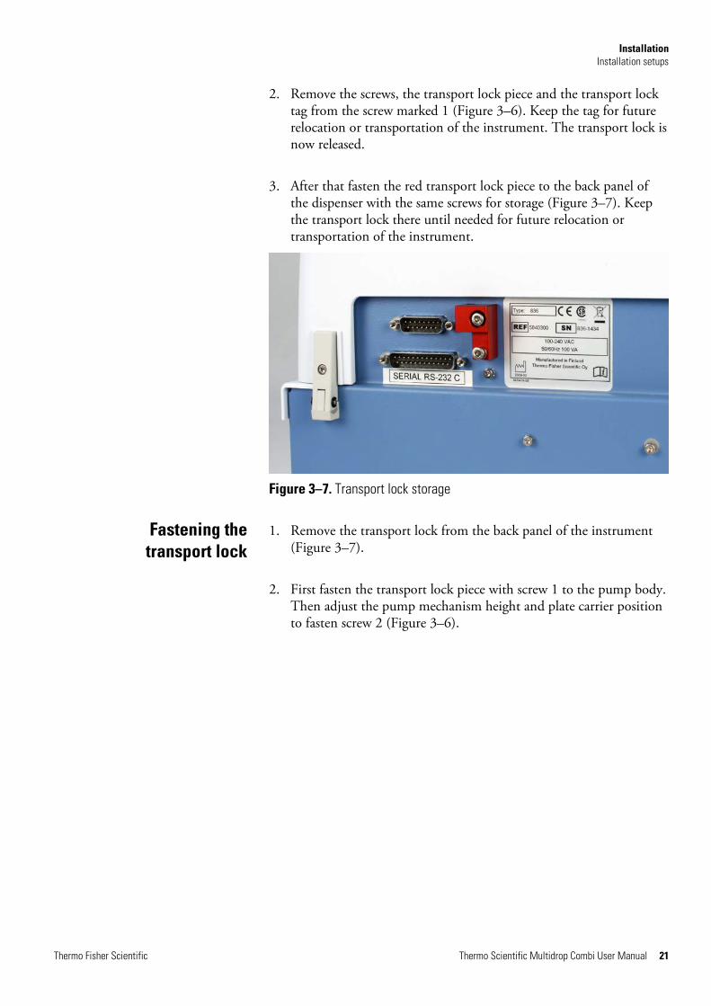
2. Remove the screws, the transport lock piece and the transport lock tag from the screw marked 1 (Figure 3–6). Keep the tag for future relocation or transportation of the instrument. The transport lock is now released.
3. After that fasten the red transport lock piece to the back panel of the dispenser with the same screws for storage (Figure 3–7). Keep the transport lock there until needed for future relocation or transportation of the instrument.
Figure 3–7. Transport lock storage
1. Remove the transport lock from the back panel of the instrument (Figure 3–7).
2. First fasten the transport lock piece with screw 1 to the pump body. Then adjust the pump mechanism height and plate carrier position to fasten screw 2 (Figure 3–6).
Fastening the transport lock

Installation Operational check
22 Thermo Scientific Multidrop Combi User Manual Thermo Fisher Scientific
Complete the following procedure without the dispensing cassette to confirm the correct functioning of the dispenser prior to normal use.
1. Connect the mains supply cable and switch the instrument on using the mains switch (Figure 2–4).
l If the instrument starts properly:
l The display lights up.
l The plate carrier moves to the home position and the pump lifting mechanism to the up position.
2. Install the priming vessel pressing it over a snap lock (Figure 3–8).
Figure 3–8. Inserting the priming vessel
3. Pull the rotor cover over the rotor (Figure 4–20).
4. Press PRIME.
l The lifting mechanism is lowered and the pump rotates as long as you press PRIME.
5. Press START.
l The dispensing protocol selected with the user interface is started.
If the protocol or predispense is not started, follow the instructions on the display or check Chapter 9: “Troubleshooting Guide”.
Operational check

Thermo Fisher Scientific Thermo Scientific Multidrop Combi User Manual 23
Chapter 4 Routine Operation
Ensure that the priming vessel is inserted correctly into its slot on the left of the plate carrier. You have fastened it correctly when you slide it over a snap lock. Make sure you have a tube assembly or a cap inserted into the drain of the priming vessel (Figure 4–9) or a vessel underneath the drain.
Figure 4–9. Priming vessel inserted into place
The Multidrop Combi can be used with dispensing cassettes with different tubing sizes.
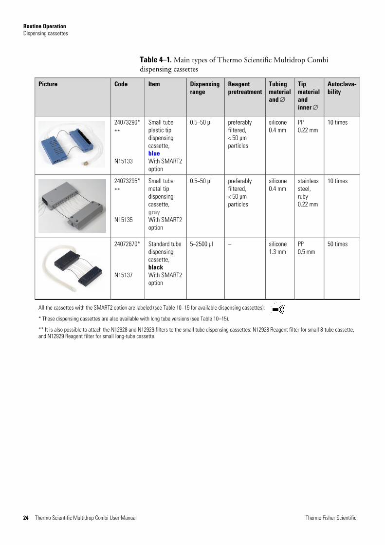
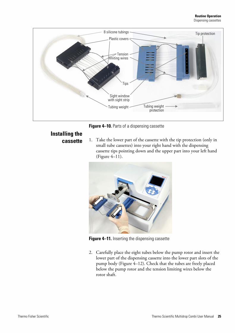
The different dispensing cassettes of the Multidrop Combi are presented below. Refer to Table 4–1, Figure 4–10 and Table 10–15.
Caution With small tube cassettes, ensure that the liquid or reagent does not contain any particles > 50 µm and that the liquid container is covered. Avoid dust or any particles > 50 µm when operating with the dispensing cassette. s
Note Do not touch the dispensing cassette tips or the tubing inlet to ensure trouble-free dispensing. Thermo Fisher Scientific assumes no liability for the use of third-party dispensing cassettes. s
Priming vessel
Dispensing cassettes
Priming vessel – with a crest in the middle where the priming liquid is aimed at to avoid splashing and a drain
Safety grooves – designed to slope and prevent fluid from entering the instrument
Routine Operation Dispensing cassettes
24 Thermo Scientific Multidrop Combi User Manual Thermo Fisher Scientific
Table 4–1. Main types of Thermo Scientific Multidrop Combi dispensing cassettes
Picture Code Item Dispensing range
Reagent pretreatment
Tubing material and ∅
Tip material and inner ∅
Autoclava-bility
24073290*
**
N15133
Small tube plastic tip dispensing cassette, blue With SMART2 option
0.5−50 µl preferably filtered, < 50 µm particles
silicone 0.4 mm
PP 0.22 mm
10 times
24073295*
**
N15135
Small tube metal tip dispensing cassette, gray With SMART2 option
0.5−50 µl preferably filtered, < 50 µm particles
silicone 0.4 mm
stainless steel, ruby 0.22 mm
10 times
24072670* N15137
Standard tube dispensing cassette, black With SMART2 option
5−2500 µl – silicone 1.3 mm
PP 0.5 mm
50 times
All the cassettes with the SMART2 option are labeled (see Table 10–15 for available dispensing cassettes):
* These dispensing cassettes are also available with long tube versions (see Table 10–15).
** It is also possible to attach the N12928 and N12929 filters to the small tube dispensing cassettes: N12928 Reagent filter for small 8-tube cassette, and N12929 Reagent filter for small long-tube cassette.
Routine Operation Dispensing cassettes
Thermo Fisher Scientific Thermo Scientific Multidrop Combi User Manual 25
Figure 4–10. Parts of a dispensing cassette
1. Take the lower part of the cassette with the tip protection (only in small tube cassettes) into your right hand with the dispensing cassette tips pointing down and the upper part into your left hand (Figure 4–11).
Figure 4–11. Inserting the dispensing cassette
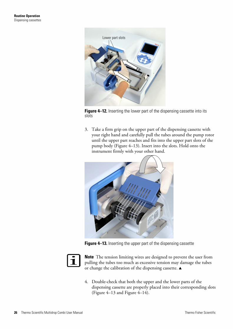
2. Carefully place the eight tubes below the pump rotor and insert the lower part of the dispensing cassette into the lower part slots of the pump body (Figure 4–12). Check that the tubes are freely placed below the pump rotor and the tension limiting wires below the rotor shaft.
Installing the cassette
Tip protection
Tubing weight protection
Plastic covers
Sight window with sight strip
8 silicone tubings
Tubing weight
Tips
Tension limiting wires
Routine Operation Dispensing cassettes
26 Thermo Scientific Multidrop Combi User Manual Thermo Fisher Scientific
Figure 4–12. Inserting the lower part of the dispensing cassette into its slots
3. Take a firm grip on the upper part of the dispensing cassette with your right hand and carefully pull the tubes around the pump rotor until the upper part reaches and fits into the upper part slots of the pump body (Figure 4–13). Insert into the slots. Hold onto the instrument firmly with your other hand.
Figure 4–13. Inserting the upper part of the dispensing cassette
Note The tension limiting wires are designed to prevent the user from pulling the tubes too much as excessive tension may damage the tubes or change the calibration of the dispensing cassette. s
4. Double-check that both the upper and the lower parts of the dispensing cassette are properly placed into their corresponding slots (Figure 4–13 and Figure 4–14).
Lower part slots

Routine Operation Dispensing cassettes
Thermo Fisher Scientific Thermo Scientific Multidrop Combi User Manual 27
Figure 4–14. Lower and upper parts of the dispensing cassette inserted evenly into their slots
5. Ensure that all the tubes are evenly placed on the rotor needles (Figure 4–15), four tubes on each half of the pump rotor.
Figure 4–15. Correct placement of all the dispensing cassette tubes
6. Ensure that the tension limiting wires have a loose fit around the rotor shaft.
7. With small tube cassettes, pull the tip protection off from the dispensing cassette once the dispensing cassette has been installed (Figure 4–16).
8. Remove the tubing weight protection by removing the rubber holder and pulling the tubing weight out of the tubing protection tube (Figure 4–17 and Figure 4–18).
Upper part slots

Routine Operation Dispensing cassettes
28 Thermo Scientific Multidrop Combi User Manual Thermo Fisher Scientific
Figure 4–16. Pulling the tip protection off from the dispensing cassette
Figure 4–17. Removing the tubing weight protection and rubber holder
Figure 4–18. Cassette with the tip and tubing weight protections removed
9. Place the tubing weight into the reagent vessel, and always ensure that there is sufficient liquid present to run the protocol.
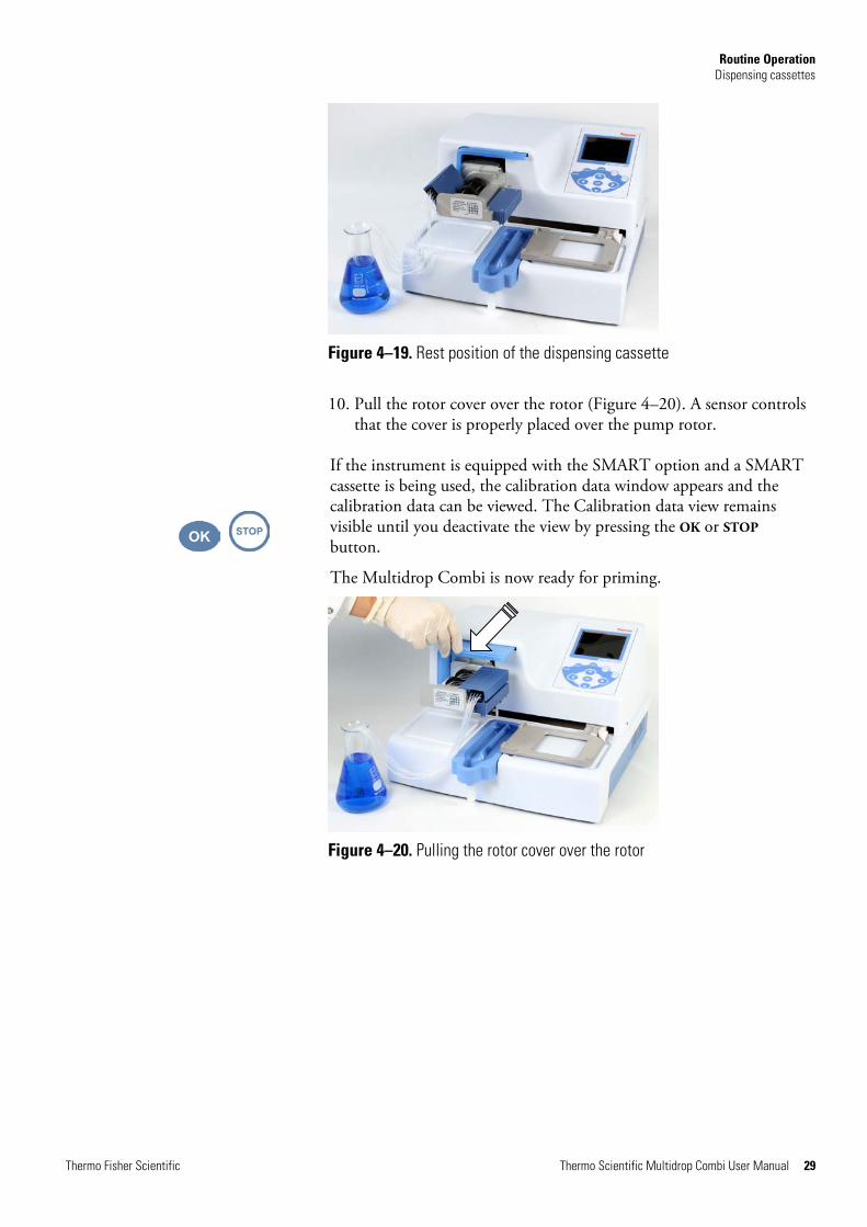
During prolonged standby, keep the cassette in its rest position (Figure 4–19).
Routine Operation Dispensing cassettes
Thermo Fisher Scientific Thermo Scientific Multidrop Combi User Manual 29
Figure 4–19. Rest position of the dispensing cassette
10. Pull the rotor cover over the rotor (Figure 4–20). A sensor controls that the cover is properly placed over the pump rotor.
If the instrument is equipped with the SMART option and a SMART cassette is being used, the calibration data window appears and the calibration data can be viewed. The Calibration data view remains visible until you deactivate the view by pressing the OK or STOP button.
The Multidrop Combi is now ready for priming.
Figure 4–20. Pulling the rotor cover over the rotor
Routine Operation Control panel
30 Thermo Scientific Multidrop Combi User Manual Thermo Fisher Scientific
This section describes the Multidrop Combi control panel and internal software.
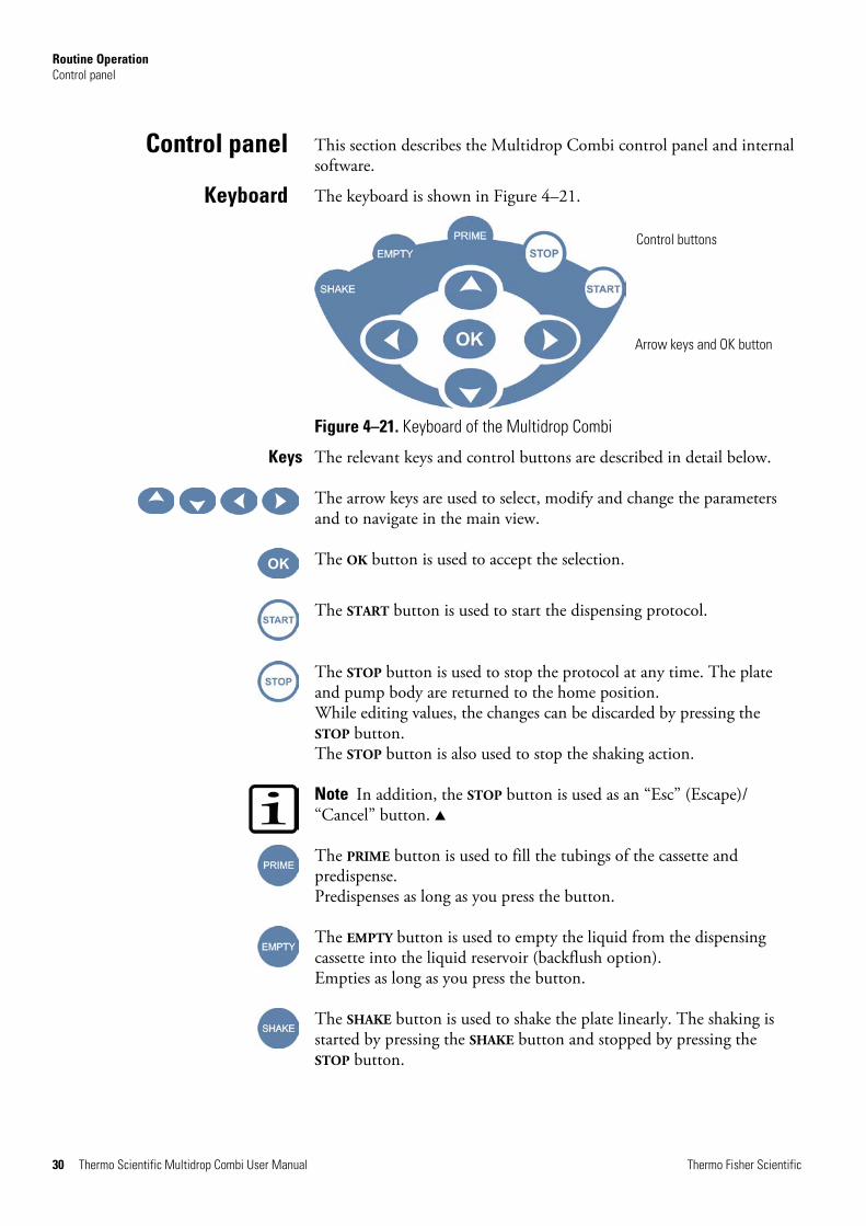
The keyboard is shown in Figure 4–21.
Figure 4–21. Keyboard of the Multidrop Combi
The relevant keys and control buttons are described in detail below.
The arrow keys are used to select, modify and change the parameters and to navigate in the main view.
The OK button is used to accept the selection.
The START button is used to start the dispensing protocol.
The STOP button is used to stop the protocol at any time. The plate and pump body are returned to the home position. While editing values, the changes can be discarded by pressing the STOP button. The STOP button is also used to stop the shaking action.
Note In addition, the STOP button is used as an “Esc” (Escape)/ “Cancel” button. s
The PRIME button is used to fill the tubings of the cassette and predispense. Predispenses as long as you press the button.
The EMPTY button is used to empty the liquid from the dispensing cassette into the liquid reservoir (backflush option). Empties as long as you press the button.
The SHAKE button is used to shake the plate linearly. The shaking is started by pressing the SHAKE button and stopped by pressing the STOP button.
Control panel
Keyboard
Keys
Control buttons
Arrow keys and OK button

Routine Operation Control panel
Thermo Fisher Scientific Thermo Scientific Multidrop Combi User Manual 31
The main view in the display is shown in Figure 4–22.
Figure 4–22. Main view on the display of the Multidrop Combi
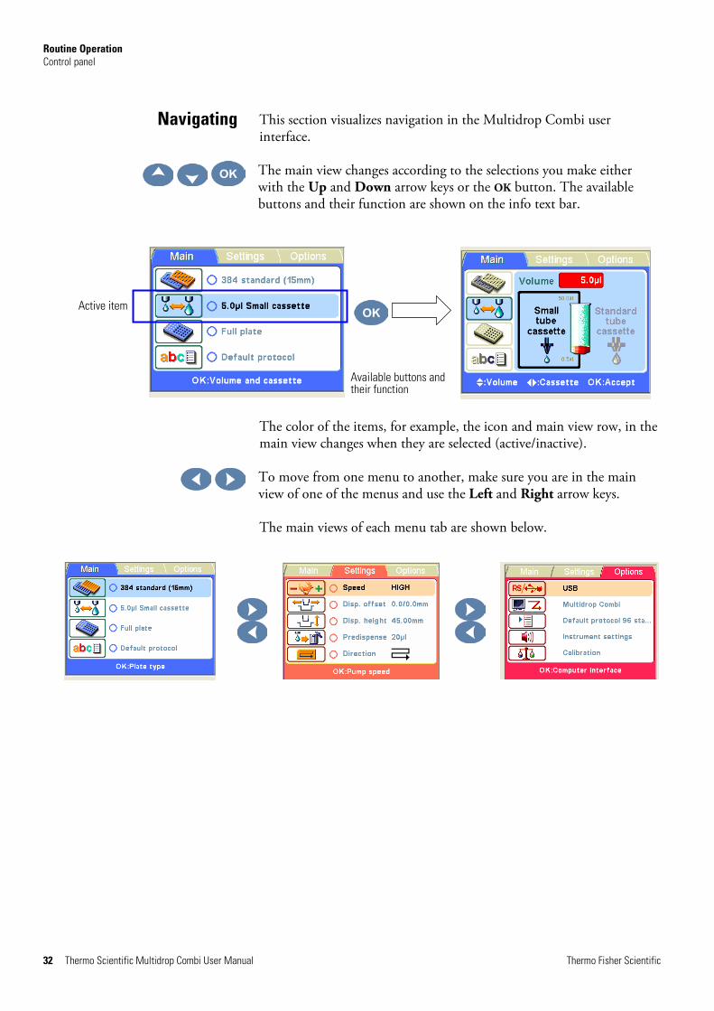
There are three menu tabs in the Multidrop Combi user interface: Main, Settings and Options. In routine use you mainly navigate in the Main menu. In advanced level options there are two extra levels, Settings and Options. You can navigate between these three menu levels using the Left and Right arrow keys.
The main view row is either colored (active) or uncolored (inactive).
All the descriptive icons used in the main view are shown in Table 4–2 below.
The info text bar shows explanatory information on how to proceed and which keys to use.
Display
Menu tabs
Info text bar
Main view row Icon
Routine Operation Control panel
32 Thermo Scientific Multidrop Combi User Manual Thermo Fisher Scientific
This section visualizes navigation in the Multidrop Combi user interface.
The main view changes according to the selections you make either with the Up and Down arrow keys or the OK button. The available buttons and their function are shown on the info text bar.
The color of the items, for example, the icon and main view row, in the main view changes when they are selected (active/inactive).
To move from one menu to another, make sure you are in the main view of one of the menus and use the Left and Right arrow keys.
The main views of each menu tab are shown below.
Navigating
Active item
Available buttons and their function

Routine Operation Control panel
Thermo Fisher Scientific Thermo Scientific Multidrop Combi User Manual 33
Table 4–2. Icons in the main view
Menu tab Icon Function
“Plate type” on page 36
“Dispensing cassette and volume” on page 38
“Column selection” on page 39
“Save and edit protocol” on page 49
“Dispensing speed” on page 42
“Dispensing offset” on page 43
“Dispensing height” on page 44
“Predispensing volume” on page 45
“Dispensing direction” on page 46
“Computer interface” on page 54
“Remote mode” on page 55
“Start-up protocol” on page 55
“Buzzer” on page 57
“Cassette calibration” on page 58
Routine Operation Dispensing
34 Thermo Scientific Multidrop Combi User Manual Thermo Fisher Scientific
You can immediately start dispensing by following the quick start guidelines below. Routine dispensing only requires to key in a few buttons.
1.
Power ON the instrument.
2.
Insert the correct dispensing cassette and the priming vessel. Close the rotor cover.
3.
Make sure you are in the Main menu.
4.
Select the plate type and insert the plate.
5.
First select the cassette type and then the dispensing volume.
6.
Keep the PRIME button down until the tubings are completely filled.
7.
Press the START button to start the protocol. The instrument dispenses the plate.
8.
Press the EMPTY button to empty the dispensing tubing.
9.
During prolonged standby, keep the cassette in its rest position.
Remove the cassette when the maximum amount of plates is dispensed or you want to change the cassette type in use. Make sure you wash the cassette properly.
10.
Power OFF the instrument.
Dispensing

Routine Operation
Thermo Fisher Scientific Thermo Scientific Multidrop Combi User Manual 35
After the instrument is turned on, make the following selections to start dispensing when you are in the Main menu: plate type, dispensing volume and cassette, and number of columns. For more information, refer to “Dispensing parameters” on page 36.
1 – Plate type; see Step 3 on p. 34.
If the plate type is correct, press
If you want to change the plate type, press
Select the plate type with
To accept, press
2 – Volume and cassette; see Step 4 on p. 34.
If the volume and the cassette are correct, press
If you want to change the volume, press
Select the appropriate cassette with
Set the needed volume with
To accept, press
3 – Columns; see Step 5 on p. 34.
If you intend to fill the whole plate, you can start dispensing after priming the instrument. If you intend to fill only part of the columns, press
and
To select the columns, navigate with
and to confirm each selection, press
Last, select Accept with When the Accept box is highlighted, press
You are now ready to start after filling the tubes through predispense.
Three key selections to start
dispensing
Selected column(s) = red

Routine Operation Using internal software
36 Thermo Scientific Multidrop Combi User Manual Thermo Fisher Scientific
This section describes procedures related to the Multidrop Combi internal software.
Multidrop Combi can also be controlled with PC software, Thermo Scientific FILLit Software for Multidrop Combi (Cat. no. 5188009). For more information, refer to Thermo Scientific FILLit Software for Multidrop Combi User Manual (Cat. no. N17561).
This section describes the relevant dispensing parameters required to create and edit a protocol. All these parameters are set in the Main menu.
Note Make the plate type selection first because all the other parameters are dependent on the plate type. s
Caution Make sure the plate lid (if used) is removed before dispensing. s
Go to the Main menu.
Press OK.
Using internal software
Dispensing parameters
Plate type
Routine Operation Dispensing parameters
Thermo Fisher Scientific Thermo Scientific Multidrop Combi User Manual 37
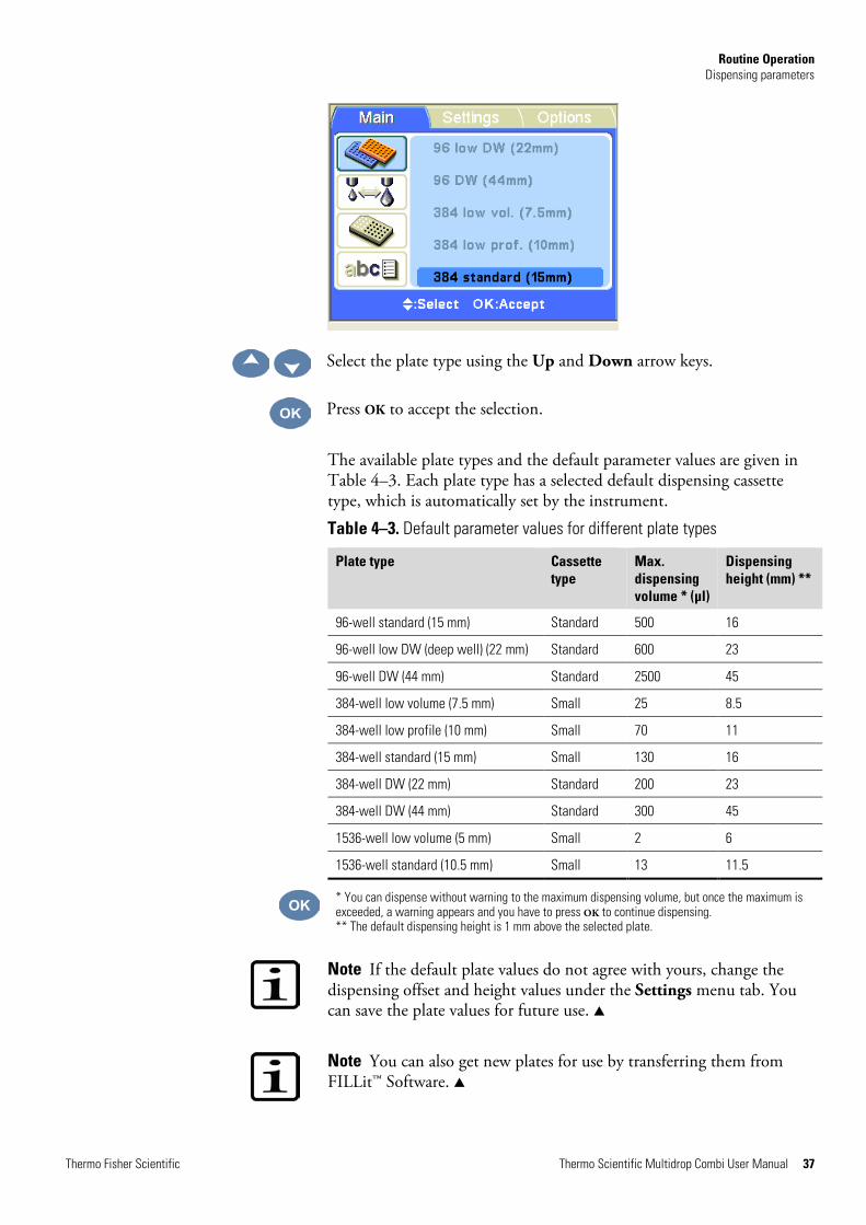
Select the plate type using the Up and Down arrow keys.
Press OK to accept the selection.
The available plate types and the default parameter values are given in Table 4–3. Each plate type has a selected default dispensing cassette type, which is automatically set by the instrument.
Table 4–3. Default parameter values for different plate types
Plate type Cassette type
Max. dispensing volume * (µl)
Dispensing height (mm) **
96-well standard (15 mm) Standard 500 16
96-well low DW (deep well) (22 mm) Standard 600 23
96-well DW (44 mm) Standard 2500 45
384-well low volume (7.5 mm) Small 25 8.5
384-well low profile (10 mm) Small 70 11
384-well standard (15 mm) Small 130 16
384-well DW (22 mm) Standard 200 23
384-well DW (44 mm) Standard 300 45
1536-well low volume (5 mm) Small 2 6
1536-well standard (10.5 mm) Small 13 11.5
* You can dispense without warning to the maximum dispensing volume, but once the maximum is exceeded, a warning appears and you have to press OK to continue dispensing. ** The default dispensing height is 1 mm above the selected plate.
Note If the default plate values do not agree with yours, change the dispensing offset and height values under the Settings menu tab. You can save the plate values for future use. s
Note You can also get new plates for use by transferring them from FILLit™ Software. s

Routine Operation Dispensing parameters
38 Thermo Scientific Multidrop Combi User Manual Thermo Fisher Scientific
There are two types of dispensing cassettes available, Small tube cassette (either plastic tip or metal tip) and Standard tube cassette. Refer to “Dispensing cassettes” on page 23 and Table 10–15. Each dispensing cassette type covers a specific volume area.
Go to the Main menu. Select the Volume and cassette row.
Press OK. The default cassette type and dispensing volume for the selected plate type are shown.
First select the cassette type using the Left and Right arrow keys.
Then select the dispensing volume using the Up and Down arrow keys. You can speed up the selection by holding down the arrow key continuously.
The minimum and maximum dispensing volumes are displayed in the Volume and cassette window. Refer to Table 4–4 below.
Table 4–4. Dispensing volumes of the cassettes
Cassette Volume range (µl) Increment (µl)
Small tube cassette 0.5…50 0.5
Standard tube cassette 5…2500 5
Dispensing cassette and volume
Max. volume
Min. volume
Routine Operation Dispensing parameters
Thermo Fisher Scientific Thermo Scientific Multidrop Combi User Manual 39
The default cassette types and dispensing volumes for different plate types are given in Table 4–3.
Accept the selections using the OK button.
Ensure that the cassette selection corresponds to the installed cassette.
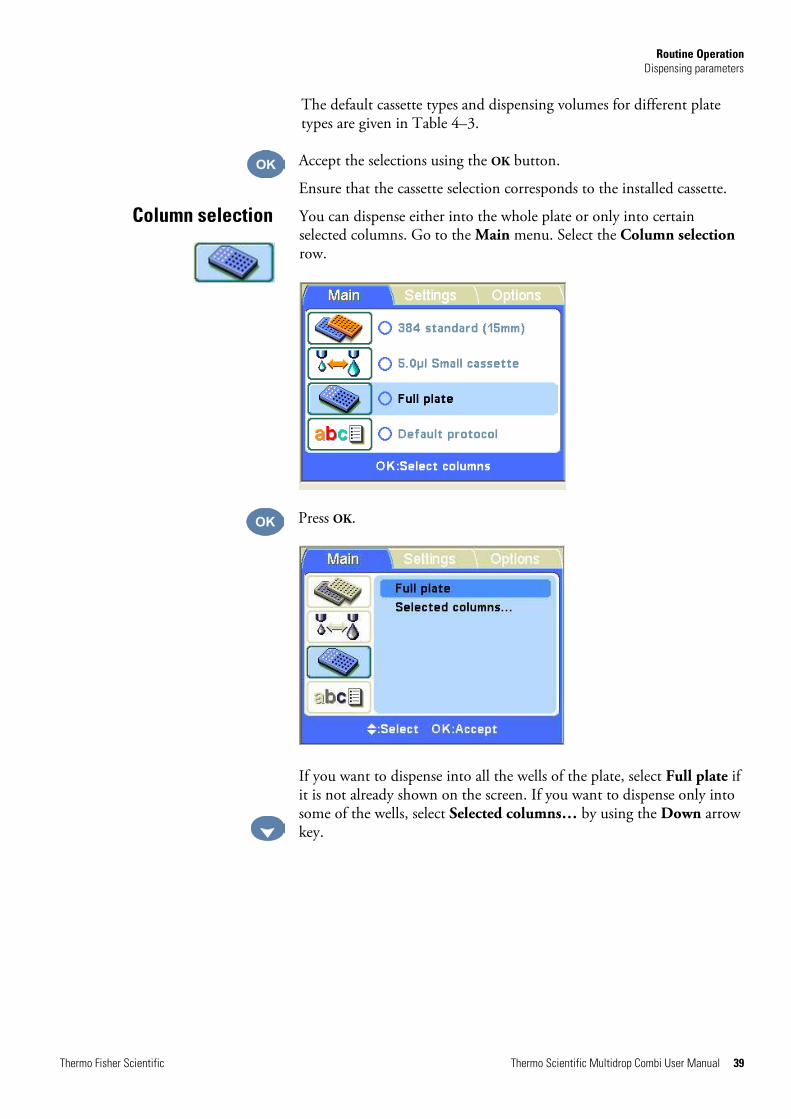
You can dispense either into the whole plate or only into certain selected columns. Go to the Main menu. Select the Column selection row.
Press OK.
If you want to dispense into all the wells of the plate, select Full plate if it is not already shown on the screen. If you want to dispense only into some of the wells, select Selected columns… by using the Down arrow key.
Column selection
Routine Operation Dispensing parameters
40 Thermo Scientific Multidrop Combi User Manual Thermo Fisher Scientific
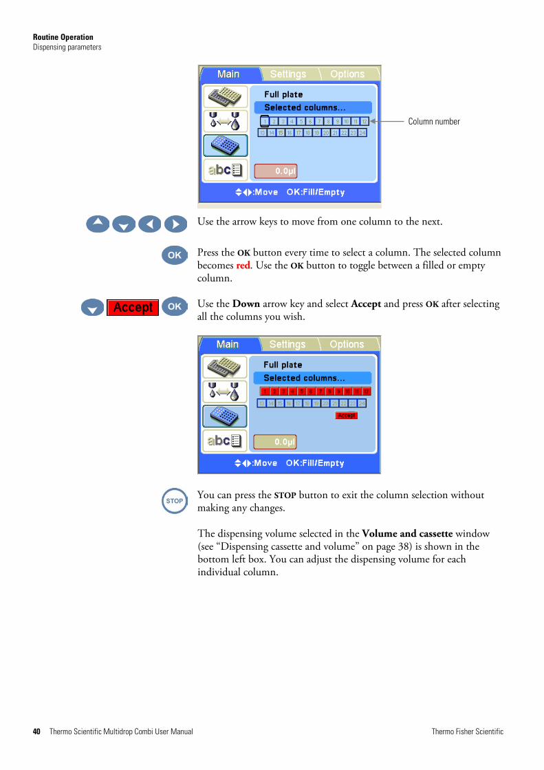
Use the arrow keys to move from one column to the next.
Press the OK button every time to select a column. The selected column becomes red. Use the OK button to toggle between a filled or empty column.
Use the Down arrow key and select Accept and press OK after selecting all the columns you wish.
You can press the STOP button to exit the column selection without making any changes.
The dispensing volume selected in the Volume and cassette window (see “Dispensing cassette and volume” on page 38) is shown in the bottom left box. You can adjust the dispensing volume for each individual column.
Column number

Routine Operation Dispensing parameters
Thermo Fisher Scientific Thermo Scientific Multidrop Combi User Manual 41
Press the OK button for 0.5 seconds. The Volume value box is now activated (bright red). Adjust the dispensing volume of the column where the cursor is located using the Up and Down arrow keys.
Press OK after selecting the desired volume.
You can press the STOP button to exit the volume selection without making any changes.
Volume value box
Routine Operation Protocol settings
42 Thermo Scientific Multidrop Combi User Manual Thermo Fisher Scientific
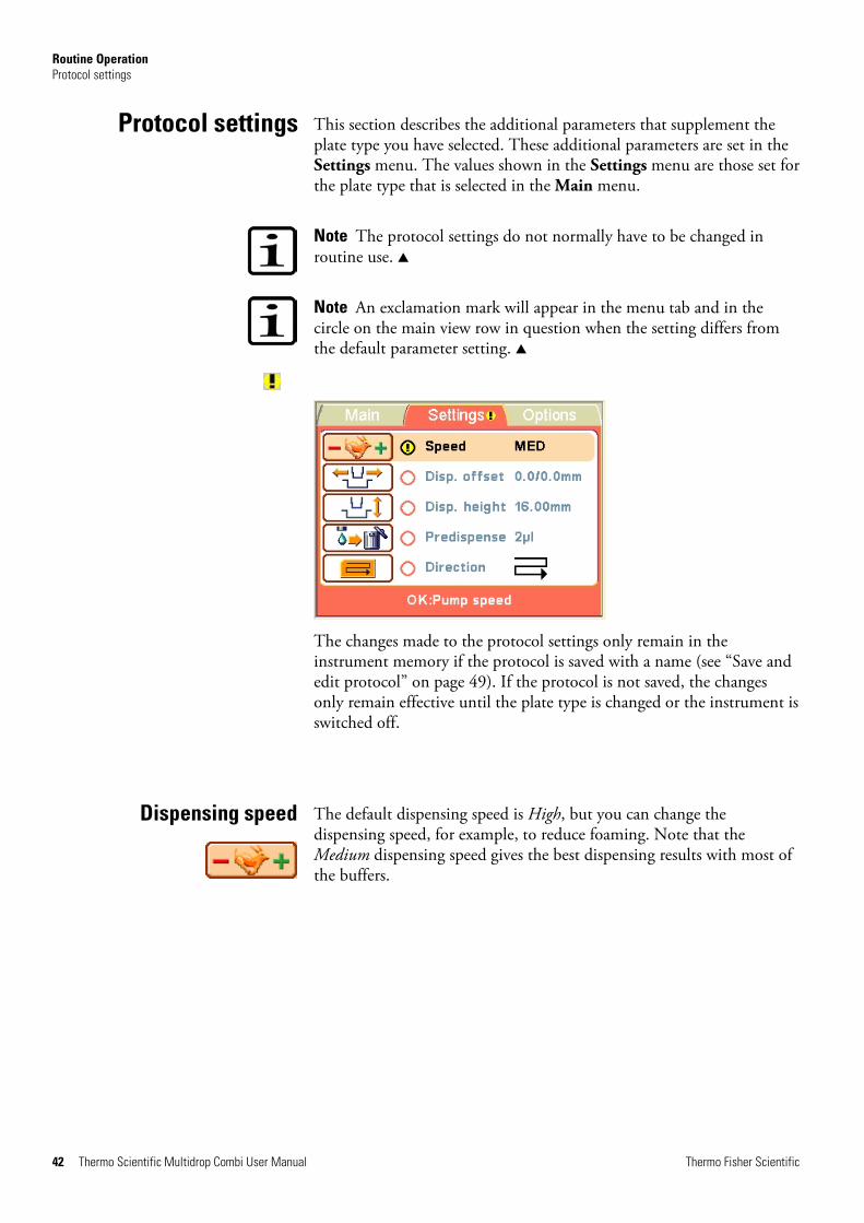
This section describes the additional parameters that supplement the plate type you have selected. These additional parameters are set in the Settings menu. The values shown in the Settings menu are those set for the plate type that is selected in the Main menu.
Note The protocol settings do not normally have to be changed in routine use. s
Note An exclamation mark will appear in the menu tab and in the circle on the main view row in question when the setting differs from the default parameter setting. s
The changes made to the protocol settings only remain in the instrument memory if the protocol is saved with a name (see “Save and edit protocol” on page 49). If the protocol is not saved, the changes only remain effective until the plate type is changed or the instrument is switched off.
The default dispensing speed is High, but you can change the dispensing speed, for example, to reduce foaming. Note that the Medium dispensing speed gives the best dispensing results with most of the buffers.
Protocol settings
Dispensing speed

Routine Operation Protocol settings
Thermo Fisher Scientific Thermo Scientific Multidrop Combi User Manual 43
Go to the Settings menu. Select the Pump speed row.
Press OK.
Use the Up and Down arrow keys to select the pump speed. The available settings are High, Med (medium) and Low. The default speed is High.
Press OK.
Table 4–5. Dispensing speeds
Speed Small tube cassette (rpm) Standard tube cassette (rpm)
HIGH 900 285
MED 733 255
LOW 567 225
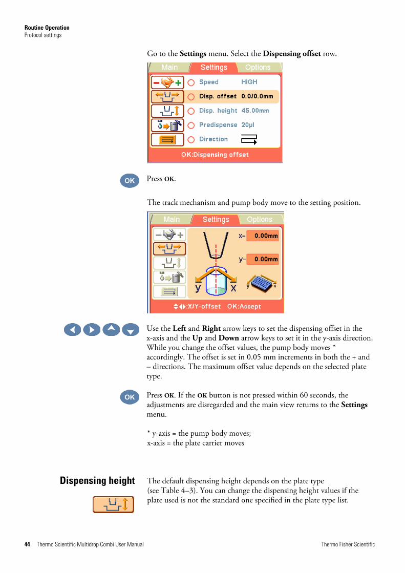
The default dispensing offset is 0.0/0.0 mm. You can change the x- and y-axis offset values if the plate used is not the standard one specified in the plate type list (see Table 4–3).
Dispensing offset
Routine Operation Protocol settings
44 Thermo Scientific Multidrop Combi User Manual Thermo Fisher Scientific
Go to the Settings menu. Select the Dispensing offset row.
Press OK.
The track mechanism and pump body move to the setting position.
Use the Left and Right arrow keys to set the dispensing offset in the x-axis and the Up and Down arrow keys to set it in the y-axis direction. While you change the offset values, the pump body moves * accordingly. The offset is set in 0.05 mm increments in both the + and – directions. The maximum offset value depends on the selected plate type.
Press OK. If the OK button is not pressed within 60 seconds, the adjustments are disregarded and the main view returns to the Settings menu.
* y-axis = the pump body moves; x-axis = the plate carrier moves
The default dispensing height depends on the plate type (see Table 4–3). You can change the dispensing height values if the plate used is not the standard one specified in the plate type list.
Dispensing height

Routine Operation Protocol settings
Thermo Fisher Scientific Thermo Scientific Multidrop Combi User Manual 45
Go to the Settings menu. Select the Dispensing height row.
Press OK.
The track mechanism and pump body move to the setting position.
Use the Up and Down arrow keys to set the dispensing height. While you change the height, the pump body moves accordingly. The height is set in 0.05 mm increments in both the up and down directions. The minimum height value depends on the selected plate type (see Table 4–3). The default dispensing height is 1 mm above the selected plate.
Press OK. If the OK button is not pressed within 60 seconds, the adjustments are disregarded and the main view returns to the Settings menu.
You can change the predispensing volume – the volume that is automatically dispensed before the start of plate filling, if necessary. Some more viscose solutions used may sometimes require extra predispensing.
Predispensing volume
Routine Operation Protocol settings
46 Thermo Scientific Multidrop Combi User Manual Thermo Fisher Scientific
Go to the Settings menu. Select the Predispense (Prime) row.
Press OK.
Use the Up and Down arrow keys to set the predispensing volume. The volume ranges from 2 (small tube cassettes)/10 (standard tube cassette) to 10000 µl in 1 µl increments. For default predispensing values for different plate types, refer to Table 4–3.
Press OK.
The row wise dispensing direction is default for each plate type. However, you may change the dispensing direction, if necessary.
Dispensing direction

Routine Operation Protocol settings
Thermo Fisher Scientific Thermo Scientific Multidrop Combi User Manual 47
Go to the Settings menu. Select the Dispensing direction row.
Press OK.
Use the Up and Down arrow keys to set the dispensing direction, row wise or column wise. Note that the whole action is only effective when 384 or 1536-well plate types are selected.
Press OK.
With the 96-well plate selection, the columns with 8 wells are filled starting from column 1 according to the selected columns, after which the plate carrier returns to the home position and the pump lifting mechanism to the up position. Row wise and column wise dispensing show no differences in 96-well plate dispensing.
With the 384-well plate selection, the columns with 16 wells are filled in two phases: first every other row (A, C, E, G, ... O) starting from the columns selected and then the pump carrier shifts sideways so that the remaining rows (B, D, F, H, ... P) are filled in the opposite order. If column wise dispensing is used, it shifts the pump carrier first sideways filling 16 wells and then the plate carrier moves dispensing over the next column.
With the 1536-well plate selection, the columns with 32 wells are filled in four phases: first every fourth row (A, E, I, M … AC) and then the
Column wise direction
Row wise direction
Routine Operation Running a protocol
48 Thermo Scientific Multidrop Combi User Manual Thermo Fisher Scientific
pump carrier shifts sideways above the rows (B, F, J, N … AD), which are then filled in the opposite order. After three shifts the remaining rows (D, H, L, P … AF) are filled. Column wise dispensing shifts the pump carrier sideways three times filling 32 wells and then the plate carrier moves the dispensing head over the next column.
In 384 and 1536-well plate mode, row wise and column wise dispensing can be effectively used.
To run a dispensing protocol, follow the steps below.
Note Do not dispense extensively without any liquid.
l Check that there is always enough liquid in the reservoir and ensure that all the tube ends are below the liquid level. Use the PEEK tubing weight supplied.
l Check after each dispensing that the priming vessel is not filled up. s
1.
Make sure you are in the Main menu.
2.
Select the plate type. The protocols are listed according to each plate type.
3.
Select the dispensing protocol from the protocol list.
4.
Keep the PRIME button down until the tubings are completely filled.
5.
Press the START button to start the protocol.
Running a protocol
Routine Operation Running a protocol
Thermo Fisher Scientific Thermo Scientific Multidrop Combi User Manual 49
Go to the Main menu. Select the Save and Edit Protocol row.
Press OK.
Press the Right arrow key to name/edit the name of your protocol.
Enter the name of your protocol.
Use the arrow keys to choose the character you want.
Press OK to enter the said character.
Save and edit protocol

Routine Operation Running a protocol
50 Thermo Scientific Multidrop Combi User Manual Thermo Fisher Scientific
... , ... ,
, ,
The available characters are: a to z, 0 to 9, hyphen (-), underline (_), and space.
Note Use max. 20 characters, including the space character. Some of the characters are broader than the others, whereby some of the names you edit will display less than 20 characters in the protocol list, shown as three dots at the displayed name. The protocol name is automatically capitalized. s
To remove characters, use the Backspace button. Use the Down arrow key (and if needed, the Left and Right arrow keys) to select the Backspace button and then the OK button to remove the character(s).
Use the Down arrow key to select the Save button and then press the OK button to save the edited protocol name.
Backspace button
Routine Operation Running a protocol
Thermo Fisher Scientific Thermo Scientific Multidrop Combi User Manual 51
The sandglass window will appear while the Save action is in progress.
The protocol name is now shown on the Save and Edit Protocol row.
You can create a maximum of 100 protocols, including the factory defined protocols.
When you save the protocol, all the following parameters are saved:
Routine Operation Running a protocol
52 Thermo Scientific Multidrop Combi User Manual Thermo Fisher Scientific
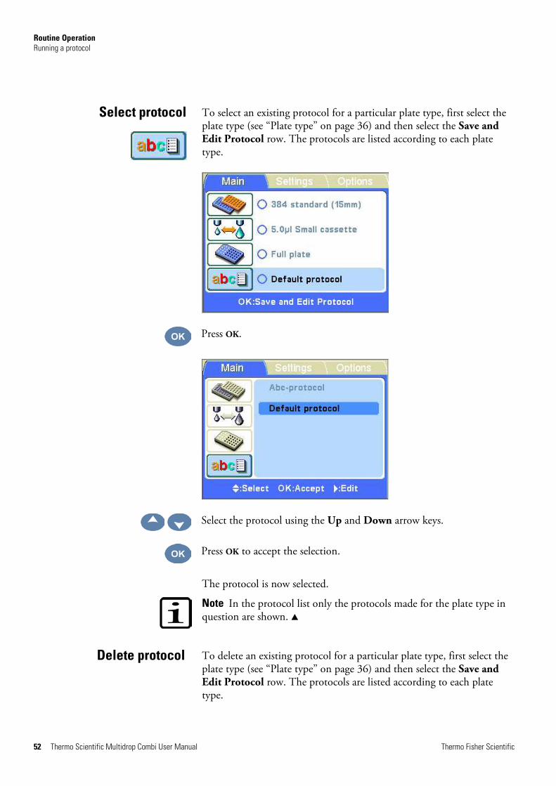
To select an existing protocol for a particular plate type, first select the plate type (see “Plate type” on page 36) and then select the Save and Edit Protocol row. The protocols are listed according to each plate type.
Press OK.
Select the protocol using the Up and Down arrow keys.
Press OK to accept the selection.
The protocol is now selected.
Note In the protocol list only the protocols made for the plate type in question are shown. s
To delete an existing protocol for a particular plate type, first select the plate type (see “Plate type” on page 36) and then select the Save and Edit Protocol row. The protocols are listed according to each plate type.
Select protocol
Delete protocol

Routine Operation Running a protocol
Thermo Fisher Scientific Thermo Scientific Multidrop Combi User Manual 53
Press OK.
Select the protocol using the Up and Down arrow keys.
Press the Right arrow key to enter the edit mode.
To delete the protocol, use the Delete button. Use the Down arrow key (and if needed, the Left and Right arrow keys) to select the Delete button and then the OK button to delete the protocol. You cannot delete default protocols (the Delete button is not activated). Also, if you have selected a protocol to be a start-up protocol, it cannot be deleted.
The protocol is now deleted.
Delete button
Routine Operation Instrument options
54 Thermo Scientific Multidrop Combi User Manual Thermo Fisher Scientific
This section describes the instrument parameters. All these parameters are set in the Options menu. The values shown in the Options menu remain in the instrument memory and are instrument specific, not protocol specific.
Note You do not normally have to change the instrument options in routine use. s
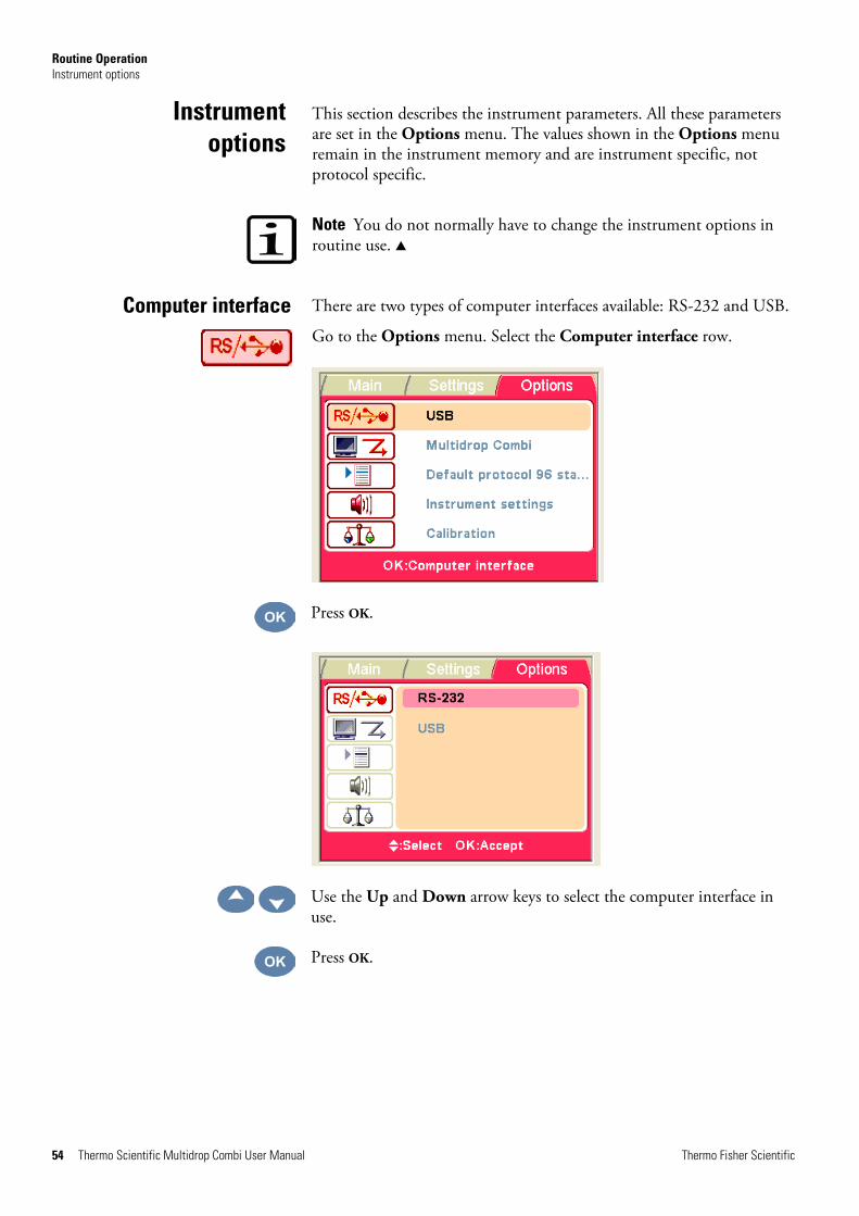
There are two types of computer interfaces available: RS-232 and USB.
Go to the Options menu. Select the Computer interface row.
Press OK.
Use the Up and Down arrow keys to select the computer interface in use.
Press OK.
Instrument options
Computer interface

Routine Operation Instrument options
Thermo Fisher Scientific Thermo Scientific Multidrop Combi User Manual 55
The Multidrop Combi can emulate the Thermo Scientific Multidrop 384 and Thermo Scientific Multidrop Micro command sets when in remote use. Thus it enables replacement of an old Multidrop unit with a Multidrop Combi. Select the dispenser in remote mode in question. Refer to “Remote control to Multidrop Combi” on page 92.
Go to the Options menu. Select the Remote mode row.
Press OK.
Use the Up and Down arrow keys to select the remote mode in use.
Press OK.
You can set which protocol is automatically selected in the Main menu when the Multidrop Combi is powered on.
Remote mode
Start-up protocol

Routine Operation Instrument options
56 Thermo Scientific Multidrop Combi User Manual Thermo Fisher Scientific
Go to the Options menu. Select the Start-up protocol row.
Press OK.
Use the Up and Down arrow keys to select the start-up protocol. The protocols are listed grouped and indented under each plate type.
Press OK.
The protocol name is appended with the plate type.
When the instrument is started up the next time, the plate type and the protocol are those just selected.
Routine Operation Instrument options
Thermo Fisher Scientific Thermo Scientific Multidrop Combi User Manual 57
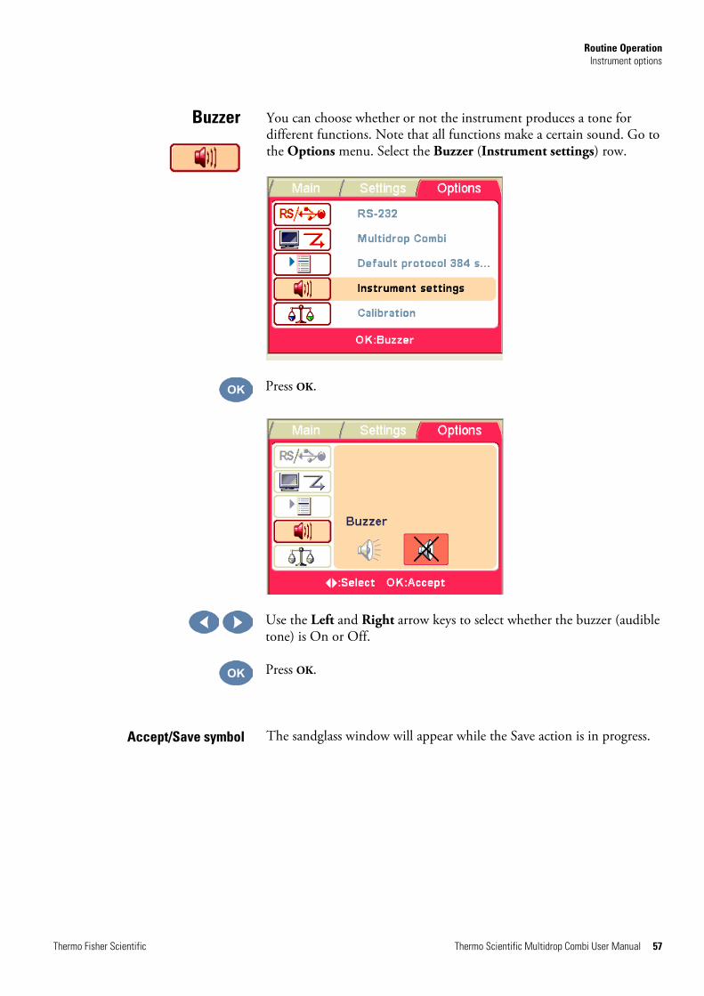
You can choose whether or not the instrument produces a tone for different functions. Note that all functions make a certain sound. Go to the Options menu. Select the Buzzer (Instrument settings) row.
Press OK.
Use the Left and Right arrow keys to select whether the buzzer (audible tone) is On or Off.
Press OK.
The sandglass window will appear while the Save action is in progress.
Buzzer
Accept/Save symbol

Routine Operation Instrument options
58 Thermo Scientific Multidrop Combi User Manual Thermo Fisher Scientific
It is possible to calibrate the cassettes for different fluids with the Gravimetric calibration tool (see “Verifying and recalibrating the dispensing cassette” on page 78).
Go to the Options menu. Select the Calibration row.
Press OK.
Use the Up and Down arrow keys to select the calibration mode. If a SMART cassette is used, the calibration data can be viewed.
Press OK.
Cassette calibration

Routine Operation Instrument options
Thermo Fisher Scientific Thermo Scientific Multidrop Combi User Manual 59
The SMART dispensing cassette has an RFID tag incorporated that contains the information when the cassette was last calibrated, the cassette type, how much the cassette has been used for dispensing and the total usage. Refer to antenna, RFID and RFID tag in the glossary.
The Multidrop Combi equipped with SMART option calculates the usage of the cassette by incrementing rotations of the pump. The number of rotations is then compared to the specified lifetime value of each cassette.
You can check the SMART cassette calibration data either by pulling the rotor cover over the rotor or by selecting Options > QC cassette values > OK.
For instance, the small tube cassette lifetime specification is 1000 plates of 384 wells @ 5 µl. This equals 60 000 rotations of the peristaltic pump. One 384-well plate @ 5 µl equals 60 rotations which is 0.1% of the total usage.
The Since last calibration percentage value will turn to zero every time the cassette is calibrated. The Total usage value will follow the lifetime of the cassette. Refer to the Calibration data display below.
If the total usage exceeds 100%, that is, is in the red, the cassette in question should be changed to ensure secure dispensing performance. However, the cassette can be further used, but in this case the user has to monitor the cassette tube wearing with care.
The serial number of the cassette is shown on the info text bar.
Press OK to exit.
Dispensing cassette with SMART option
Routine Operation Screen saver
60 Thermo Scientific Multidrop Combi User Manual Thermo Fisher Scientific
Table 4–6. Total usage of cassettes
Small tube cassette * Standard tube cassette
100% usage
1000 pcs of 384-well plates @ 5 µl
100% usage
3000 pcs of 96-well plates @ 100 µl
50% usage
500 pcs of 384-well plates @ 5 µl
50% usage
1500 pcs of 96-well plates @ 100 µl
25% usage
250 pcs of 384-well plates @ 5 µl
25% usage
750 pcs of 96-well plates @ 100 µl
* If you dispense 1 µl into 1536-well plates with the small tube cassette, then the 100% usage equals approximately 1200 plates.
The Multidrop Combi screen saver shown below appears when the instrument has not been used for 20 minutes. You can deactivate the screen saver and return to the previous display by pressing any key.
To shut down the Multidrop Combi, follow these steps:
Warning Remove any microplates still on the instrument. Dispose of all microplates and strips as biohazardous waste. s
1. After all the plates have been dispensed, press the EMPTY button to
return the reagent or liquid from the tubes to the reservoir.
2. If there is only a break of a few minutes in dispensing, no washing
or cleaning of the tubes is necessary. However, after pressing the EMPTY button, release the tubing tension by pulling the upper part of the dispensing cassette from its slots and place it into its rest position slots located on the left-hand side of the rotor (Figure 4–19).
Screen saver
Shutdown

Routine Operation Emergency situations
Thermo Fisher Scientific Thermo Scientific Multidrop Combi User Manual 61
3. If there is a longer break (for example, a day), wash the dispensing cassette by priming it with deionized distilled water or with special washing detergent if necessary.
4. After washing and emptying, store the dispensing cassette in the rest position (Figure 4–19).
5. Switch the Multidrop Combi off by pressing the mains switch (Figure 2–4) at the left of the back panel of the instrument into the OFF position.
6. Wipe the instrument surfaces with a soft cloth or tissue paper moistened with deionized distilled water, a mild detergent (SDS, sodium dodecyl sulfate) or soap solution.
7. If you have spilled infectious agents on the dispenser, disinfect with 70% alcohol or some other disinfectant (see “Decontamination procedure” on page 63).
Note Keep the dispensing cassette in the rest position when the dispensing cassette is not in use (Figure 4–19). s
In case there is any abnormal situation during operation, such as fluids spilling inside the instrument, follow these steps:
1. Switch OFF the instrument (Figure 2–4).
2. Unplug the instrument immediately from the power supply.
3. Carry out appropriate corrective measures. However, do not disassemble the instrument.
4. If the corrective measures taken do not help, contact authorized technical service or your local Thermo Fisher Scientific representative.
Emergency situations

Thermo Fisher Scientific Thermo Scientific Multidrop Combi User Manual 62
Chapter 5 Maintenance
This section describes issues related to maintenance of the instrument.
For reliable daily operation, keep the instrument free of dust and liquid spills. To prevent unnecessary wear or hazards, follow the routine and service procedures described below at the frequency with which they should be applied.
Clean the outside of the instrument periodically with a cloth dampened with water or a mild detergent or 70% ethanol when necessary. Immediately wipe away spilled saline solutions, solvents, acids or alkaline solutions from outer surfaces to prevent damage.
Abrasive cleaning agents are not recommended, because they are likely to damage the plastic instrument cover.
Caution The surfaces can be cleaned with most laboratory detergents. Dilute the cleaning agent as recommended by the manufacturer. Do not expose the surfaces to concentrated acids or concentrated alcohols for prolonged periods of time as damage may occur. s
It is recommended to service the instrument at least yearly. Refer to “Service contracts” on page 65.
If you believe that liquid has entered the Multidrop Combi, first switch the instrument off (Figure 2–4) and unplug the instrument. Carry out corrective measures. Refer to “Emergency situations” on page 61 and “Decontamination procedure” on page 63 for aid. If necessary, contact your local Thermo Fisher Scientific service representative. Refer to “Packing for service” on page 65.
Warning If any surfaces are contaminated with biohazardous material, a mild sterilizing solution should be used. s
Caution Do not use alcohol for cleaning the rotor, use water instead. s
Caution Do not autoclave any part of this instrument except the priming vessel and the dispensing cassettes. s
A) Instrument maintenance
Regular and preventive
maintenance

Maintenance Disposal of materials
Thermo Fisher Scientific Thermo Scientific Multidrop Combi User Manual 63
Follow laboratory and country-specific procedures for biohazardous or radioactive waste disposal. Refer to local regulations for the disposal of infectious material.
Warning The samples can be potentially infectious. Dispose of all used dispensing cassettes, plates, strips, priming vessels, disposable gloves, syringes, disposable tips, and so on as biohazardous waste. s
If you have spilled infectious agents, carry out the decontamination procedure.
Decontamination should be performed in accordance with normal laboratory procedures. Any decontamination instructions provided with the reagents used should be followed.
It is strongly recommended to perform the complete decontamination procedure before relocating the instrument from one laboratory to another.
Example of decontaminants:
l Ethanol 70%
l Virkon solution 1–3%
l Glutaraldehyde solution 4%
l Chloramine T
l Microcide SQ 1:64
l Decon 90 min. 4%
Caution If local or laboratory regulations prescribe regular decontamination, it is not advisable to use formaldehyde, since even small traces of formaldehyde negatively affect the enzyme being used in EIA tests resulting in inconsistent test results. s
Warning The decontamination procedure should be performed by authorized trained personnel in a well-ventilated room wearing disposable gloves, protective glasses and clothing. s
1. Prepare the decontaminant: for example, 1–3% Virkon solution, or 200 ml 4% glutaraldehyde solution (or another agent recommended by your safety officer).
2. Empty the reagent container. Ensure that you are wearing disposable gloves.
Disposal of materials
Decontamination procedure

Maintenance Decontamination procedure
64 Thermo Scientific Multidrop Combi User Manual Thermo Fisher Scientific
3. Switch OFF the power (Figure 2–4) and disconnect the mains supply cable.
4. Disinfect the outside of the instrument using a cloth dampened with 70% ethanol.
5. Place the dispensing cassette, for example, in 1–3% Virkon solution or 4% glutaraldehyde solution for 10 minutes and rinse it with deionized distilled water. The dispensing cassette can alternatively be autoclaved.
6. Place the instrument in a large plastic bag.
7. Place a cloth soaked in the prepared solution into the bag. Ensure that the cloth does not come into contact with the instrument.
8. Close the bag firmly and leave the instrument in the bag for at least 24 hours.
9. Remove the instrument from the bag.
10. Clean the instrument using a mild detergent.
11. Remove any stains using 70% ethanol.
12. Flush the fluid path of the instrument with deionized distilled water using the predispensing procedure.
13. Wash and disinfect the reagent containers.
14. After performing this decontamination procedure, enclose a signed and dated Certificate of Decontamination both inside the transport package and attached to the outside of the package (see Appendix B: “Certificate of Decontamination”).

Maintenance Packing for service
Thermo Fisher Scientific Thermo Scientific Multidrop Combi User Manual 65
To pack for service, follow the guidelines presented below.
Caution It is important that the instrument is thoroughly decontaminated before it is removed from the laboratory or any servicing is performed on it. s
When you ship the instrument for service, remember to:
l Inform about the use of hazardous materials.
l Decontaminate the instrument beforehand. Empty the tubings of the dispenser and remove any loose items from the plate carrier, for example, plates and priming vessels before decontamination.
l Install the transport lock of the instrument. Refer to “Fastening the transport lock” on page 21.
l Pack the instrument according to the enclosed packing instructions.
l Use the original packaging to ensure that no damage occurs to the instrument during shipping. Any damage incurs additional labor charges.
l Enclose a dated and signed Certificate of Decontamination (see Appendix B: “Certificate of Decontamination”) both inside and attached to the outside of the package, in which you return your instrument (or other items).
l Enclose the return authorization number (RGA) given by your local Thermo Fisher Scientific representative.
l Indicate the fault after contacting your local Thermo Fisher Scientific representative or the Thermo Fisher Scientific technical service department.
Refer to “General specifications” on page 89 for details on storage and transportation temperatures.
It is recommended to maintain and service the instrument regularly every 12 months on a contract basis by the manufacturer's trained service engineers. This ensures that the product is properly maintained and gives trouble-free service. Contact the Thermo Fisher Scientific service representative for more details.
Packing for service
Service contracts
Maintenance Disposal of the instrument
66 Thermo Scientific Multidrop Combi User Manual Thermo Fisher Scientific
If the Multidrop Combi has to be disposed of, follow the guidelines below.
Warning Decontaminate the instrument before disposal. Refer to “Decontamination procedure” on page 63. s
Follow laboratory and country-specific procedures for biohazardous or radioactive waste disposal.
Dispose of the instrument according to the legislation stipulated by the local authorities concerning take-back of electronic equipment and waste. The proposals for the procedures vary by country.
Pollution degree 2 (see “Safety specifications” on page 90) Method of disposal Electronic waste Contaminated waste
(Infectious waste)
Regarding the original packaging and packing materials, use the recycling operators known to you.
For more information, contact your local Thermo Fisher Scientific representative.
This section describes issues related to maintenance of the dispensing cassettes.
To wash the dispensing cassette, follow these steps:
1. Wash the tubes by predispensing them with deionized distilled water. Make sure all the tubes are washed properly.
2. If cleaning with water is insufficient, use a mild laboratory detergent and then predispense with large amounts of deionized distilled water.
3. Empty the tubings of the dispensing cassette. The dispensing cassette can be dried at room temperature.
4. After washing, store the dispensing cassette in the rest position (Figure 4–19).
Disposal of the instrument
B) Dispensing cassette maintenance
Washing the dispensing cassette

Maintenance B) Dispensing cassette maintenance
Thermo Fisher Scientific Thermo Scientific Multidrop Combi User Manual 67
5. If the instrument is not used for a couple of hours, insert the dispensing cassette into the rest position (Figure 4–19). Refer to “Shutdown” on page 60. Handle the dispensing cassette with great care so that you do not damage the tubes and dispensing tips. These factors affect the useful life of the dispensing cassette.
Caution With small tube cassettes, ensure that the liquid or reagent does not contain any particles > 50 µm and that the liquid container is covered. Avoid dust or any particles > 50 µm when operating with the dispensing cassette. s
The following instructions are valid for the Small tube plastic tip dispensing cassette and the Standard tube dispensing cassette. If the tip(s) are clogged, you can first try the following alternative procedures to remove the blockage.
1. Press the EMPTY button for a few seconds. Then press the PRIME
button for a few seconds.
2. Place a liquid reservoir filled with deionized distilled water under
the cassette tips so that the tips are submerged in liquid and press the EMPTY button.
3. Clean the tips according to the procedure described below (gray metal tip cassette only). Use the cleaning tool provided.
Note To avoid particles re-entering the reagent, place the tubing end weight into a separate vessel while you empty the tubing. s
The following cleaning instructions are only valid for the Small tube metal tip dispensing cassette.
1. Unfasten the four screws of the cover.
2. Detach the tubing from the tips and remove the tip holder from the Small tube metal tip dispensing cassette (Cat. no. 24073295). Avoid touching the inlet of the tip.
Cleaning the tips
Cleaning the metal tips

Maintenance B) Dispensing cassette maintenance
68 Thermo Scientific Multidrop Combi User Manual Thermo Fisher Scientific
3. Fill the 20 ml syringe (provided with the cassette) with deionized distilled water, ethanol or another suitable liquid.
4. Attach the syringe with a round filter unit (provided) and then attach the pink adapter with the short piece of tubing (provided) onto the filter unit.
5. Press liquid through the syringe to wash out any particles from the tubing.
6. Attach the short tubing onto the outlet of the tip and press liquid through the syringe (Figure 5–23).
Figure 5–23. Pressing liquid through the tip
7. To verify the cleaning, remove the tubing from the tip outlet and attach it to the inlet. Press the liquid through the tip and inspect the jet coming through the tip outlet with the small orifice.
8. Insert the tubing back onto the tips and place the tip holder back into the cassette. Ensure that the tubing does not twist. Avoid touching the tip inlets.
9. Close the cover by fastening the four screws.
Both small tube cassettes can be autoclaved 10 times and the standard tube cassette 50 times depending on the reagent used.
The autoclaving conditions of the dispensing cassettes are as follows: 1 bar pressure at 121°C for 20 minutes.
Warning After autoclaving, the dispensing cassette must cool down at least 2 hours to room temperature before use. s
Autoclaving the dispensing cassette

Maintenance Changing the tubing set
Thermo Fisher Scientific Thermo Scientific Multidrop Combi User Manual 69
With the Standard tube dispensing cassette the tubing set can be changed according to the instructions below. First the tip band is changed and then the new tubing set is fitted.
1. Place the dispensing cassette onto the laboratory bench with the dispensing tips pointing down.
2. Unfasten the four cover retaining screws of the lower part of the dispensing cassette (Figure 5–24).
Figure 5–24. Removing the cover plate of the lower part of the dispensing cassette
3. Remove the tip manifold, the tube fasteners and the rest of the tubing from the lower part of the dispensing cassette. Then detach the tip band from the tubing by pulling the tubes away from the tip band (Figure 5–25).
Figure 5–25. Removing the old tip band
4. Replace the tip band (Figure 5–26). The tips of the tip band must be clean to function correctly (Figure 5–27).
Figure 5–26. Tip band removed
Changing the tubing set
Changing the tip band
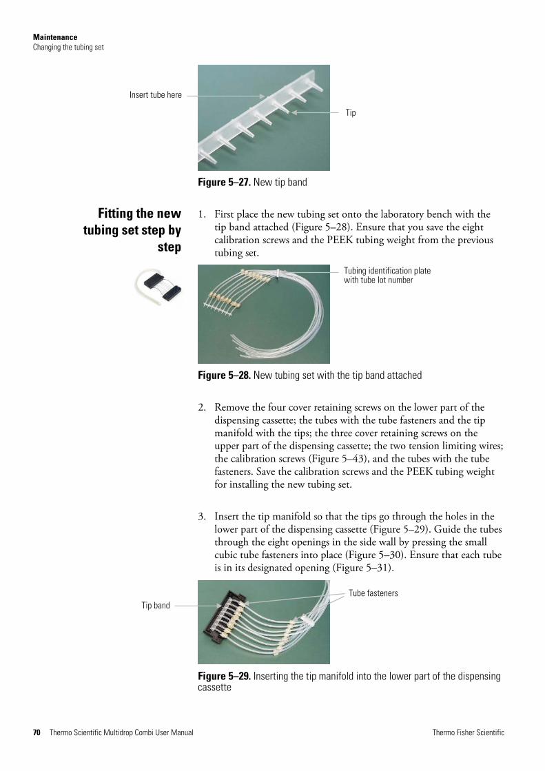
Maintenance Changing the tubing set
70 Thermo Scientific Multidrop Combi User Manual Thermo Fisher Scientific
Figure 5–27. New tip band
1. First place the new tubing set onto the laboratory bench with the tip band attached (Figure 5–28). Ensure that you save the eight calibration screws and the PEEK tubing weight from the previous tubing set.
Figure 5–28. New tubing set with the tip band attached
2. Remove the four cover retaining screws on the lower part of the dispensing cassette; the tubes with the tube fasteners and the tip manifold with the tips; the three cover retaining screws on the upper part of the dispensing cassette; the two tension limiting wires; the calibration screws (Figure 5–43), and the tubes with the tube fasteners. Save the calibration screws and the PEEK tubing weight for installing the new tubing set.
3. Insert the tip manifold so that the tips go through the holes in the lower part of the dispensing cassette (Figure 5–29). Guide the tubes through the eight openings in the side wall by pressing the small cubic tube fasteners into place (Figure 5–30). Ensure that each tube is in its designated opening (Figure 5–31).
Figure 5–29. Inserting the tip manifold into the lower part of the dispensing cassette
Fitting the new tubing set step by
step
Tip
Insert tube here
Tubing identification plate with tube lot number
Tube fasteners Tip band
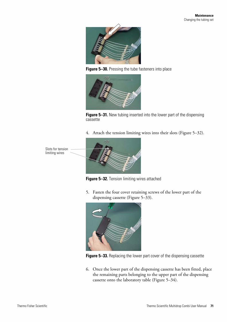
Maintenance Changing the tubing set
Thermo Fisher Scientific Thermo Scientific Multidrop Combi User Manual 71
Figure 5–30. Pressing the tube fasteners into place
Figure 5–31. New tubing inserted into the lower part of the dispensing cassette
4. Attach the tension limiting wires into their slots (Figure 5–32).
Figure 5–32. Tension limiting wires attached
5. Fasten the four cover retaining screws of the lower part of the dispensing cassette (Figure 5–33).
Figure 5–33. Replacing the lower part cover of the dispensing cassette
6. Once the lower part of the dispensing cassette has been fitted, place the remaining parts belonging to the upper part of the dispensing cassette onto the laboratory table (Figure 5–34).
Slots for tension limiting wires
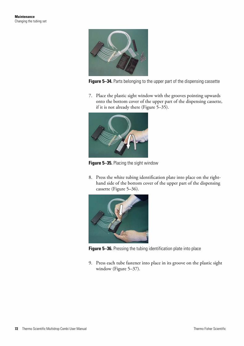
Maintenance Changing the tubing set
72 Thermo Scientific Multidrop Combi User Manual Thermo Fisher Scientific
Figure 5–34. Parts belonging to the upper part of the dispensing cassette
7. Place the plastic sight window with the grooves pointing upwards onto the bottom cover of the upper part of the dispensing cassette, if it is not already there (Figure 5–35).
Figure 5–35. Placing the sight window
8. Press the white tubing identification plate into place on the right-hand side of the bottom cover of the upper part of the dispensing cassette (Figure 5–36).
Figure 5–36. Pressing the tubing identification plate into place
9. Press each tube fastener into place in its groove on the plastic sight window (Figure 5–37).
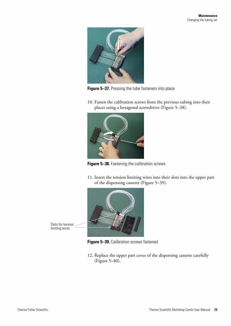
Maintenance Changing the tubing set
Thermo Fisher Scientific Thermo Scientific Multidrop Combi User Manual 73
Figure 5–37. Pressing the tube fasteners into place
10. Fasten the calibration screws from the previous tubing into their places using a hexagonal screwdriver (Figure 5–38).
Figure 5–38. Fastening the calibration screws
11. Insert the tension limiting wires into their slots into the upper part of the dispensing cassette (Figure 5–39).
Figure 5–39. Calibration screws fastened
12. Replace the upper part cover of the dispensing cassette carefully (Figure 5–40).
Slots for tension limiting wires

Maintenance Changing the tubing set
74 Thermo Scientific Multidrop Combi User Manual Thermo Fisher Scientific
Figure 5–40. Replacing the cover of the upper part of the dispensing cassette
13. Ensure that you do not get the tubing trapped or bent between the bottom and upper cover of the upper part of the dispensing cassette (Figure 5–41).
Figure 5–41. Ensuring the tubing does not get trapped
14. Fasten the three cover retaining screws of the upper part of the dispensing cassette, leaving the front screw slightly open (Figure 5–42).
Figure 5–42. Fastening the cover retaining screws
15. Insert the calibration screw cover easier by lifting or bending the upper cover slightly (Figure 5–43).
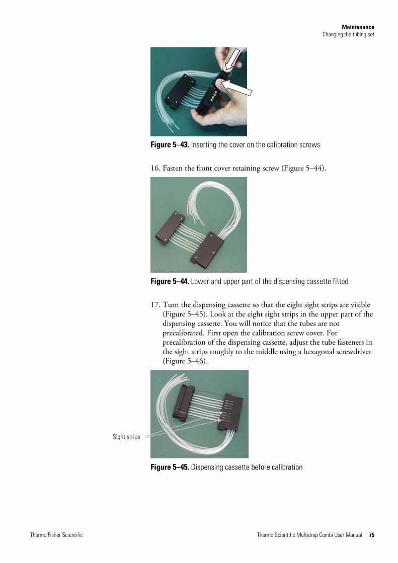
Maintenance Changing the tubing set
Thermo Fisher Scientific Thermo Scientific Multidrop Combi User Manual 75
Figure 5–43. Inserting the cover on the calibration screws
16. Fasten the front cover retaining screw (Figure 5–44).
Figure 5–44. Lower and upper part of the dispensing cassette fitted
17. Turn the dispensing cassette so that the eight sight strips are visible (Figure 5–45). Look at the eight sight strips in the upper part of the dispensing cassette. You will notice that the tubes are not precalibrated. First open the calibration screw cover. For precalibration of the dispensing cassette, adjust the tube fasteners in the sight strips roughly to the middle using a hexagonal screwdriver (Figure 5–46).
Figure 5–45. Dispensing cassette before calibration
Sight strips
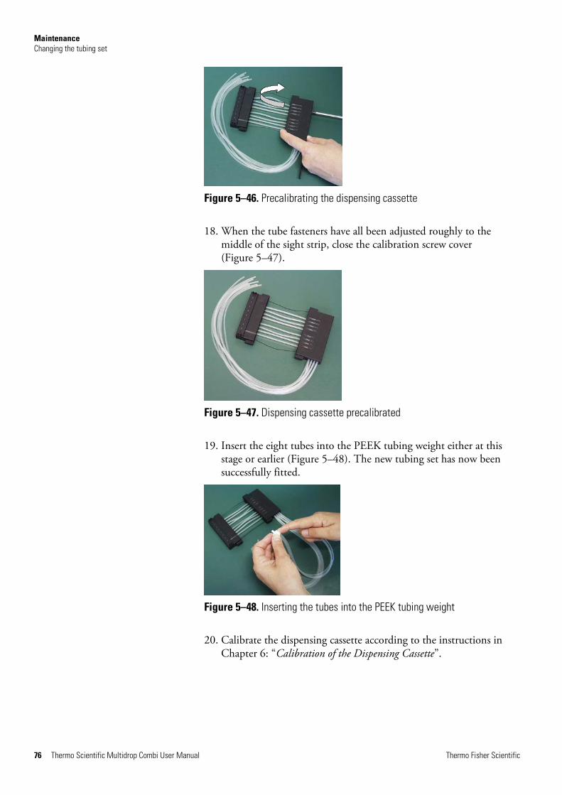
Maintenance Changing the tubing set
76 Thermo Scientific Multidrop Combi User Manual Thermo Fisher Scientific
Figure 5–46. Precalibrating the dispensing cassette
18. When the tube fasteners have all been adjusted roughly to the middle of the sight strip, close the calibration screw cover (Figure 5–47).
Figure 5–47. Dispensing cassette precalibrated
19. Insert the eight tubes into the PEEK tubing weight either at this stage or earlier (Figure 5–48). The new tubing set has now been successfully fitted.
Figure 5–48. Inserting the tubes into the PEEK tubing weight
20. Calibrate the dispensing cassette according to the instructions in Chapter 6: “Calibration of the Dispensing Cassette”.
Maintenance Disposal of the dispensing cassette
Thermo Fisher Scientific Thermo Scientific Multidrop Combi User Manual 77
Dispose of the dispensing cassette according to the legislation stipulated by the local authorities concerning take-back of the above-mentioned materials. The proposals for the procedures vary by country.
Warning The dispensing cassette may contain biohazardous materials depending on the use of the cassette. It consists of: PEEK, silicone, stainless steel, PA (polyamide), and PP (polypropylene). s
Disposal of the dispensing cassette

Thermo Fisher Scientific Thermo Scientific Multidrop Combi User Manual 78
Chapter 6 Calibration of the Dispensing Cassette
The verification and recalibration instructions cover the following three sections using the methods mentioned: accuracy verification (gravimetric); precision verification (photometric), and calibration (gravimetric).
The dispensing cassette has been calibrated by the manufacturer with deionized distilled water at 22°C ± 2°C. It is recommended to recalibrate the dispensing cassettes at least monthly, depending on the frequency of use and the liquids used. It is recommended that you recalibrate the dispensing cassette if you forget the cassette in the Multidrop Combi under tension for prolonged periods, for example, a weekend or longer. You should also check the calibration when liquid types other than water are used.
For accuracy verification, use the example table (Table 6–8) as a model when you fill out the results in the enclosed empty table (Table 6–9) in the accuracy verification worksheet.
The volume conversion factor (Z) for water to change the weights into volumes at different temperatures is presented in Table 6–7.
The gravimetric method of accuracy verification requires you to weigh each individual strip that contains water to be dispensed from the Multidrop Combi. The analytical balance that you use should be well maintained, calibrated with an appropriate set of certified weights, and capable of reading with a resolution of at least 0.1 mg, preferably 0.01 mg. The gravimetric method also requires a thermometer that should be calibrated and readable to 0.5°C.
The following materials and equipment are required for accuracy verification:
l Multidrop Combi with the dispensing cassette to be verified inserted
l Analytical balance (resolution at least 0.1 mg, preferably 0.01 mg)
l Calibrated thermometer (readable to 0.5°C)
l 96-well plate with 8 x 12 well microstrips
Verifying and recalibrating the
dispensing cassette
Accuracy verification
(gravimetric)
Materials and equipment needed for accuracy
verification

Calibration of the Dispensing Cassette Verifying and recalibrating the dispensing cassette
Thermo Fisher Scientific Thermo Scientific Multidrop Combi User Manual 79
l Disposable gloves
l High-purity water (deionized distilled water)
l Photocopy of the accuracy verification worksheet from this manual (p. 80)
1. Install the dispensing cassette (see “Installing the cassette” on page 25).
2. Pull the rotor cover over the rotor.
3. Ensure that the priming vessel is installed.
4. Set the Multidrop Combi parameters as follows (see “Dispensing parameters” on page 36):
Plate type: 96 standard (15mm) Dispensing volume and cassette: 10 µl (small tube cassette)/100 µl (standard tube cassette) Selected columns: 1−10
5. Mark and weigh each strip separately beforehand (Tare column). Use disposable gloves when handling and weighing the strips. Refer to Table 6–9.
6. Place the 96-well plate with the 8 x 12 well microstrips into the plate carrier of the Multidrop Combi.
7. Use high-purity water. Press the PRIME button until all eight
channels are dispensing continuously into the priming vessel.
8. Press the START button to start the first dispensing. Wait until all
10 columns have been dispensed. Repeat this step until dispensing has taken place 5 times in all with the small tube cassette (final volume per well ~ 50 µl) or once with the standard tube cassette (final volume per well ~ 100 µl).
9. Weigh each dispensed strip (Gross column) immediately after dispensing to avoid evaporation. The water that you use in the gravimetric method may be subject to evaporation depending on the environmental conditions during accuracy verification. Refer to Table 6–7.
Accuracy verification procedure
Calibration of the Dispensing Cassette Verifying and recalibrating the dispensing cassette
80 Thermo Scientific Multidrop Combi User Manual Thermo Fisher Scientific
10. Calculate the net weights of the dispensed strips (Net column), the dispensed volume per well in mg (Dispensed weight per well (mg) column), the dispensed volume per well in µl (Measured volume (µl) column), and the inaccuracy percentage (Inaccuracy % column) as in the example table. Refer to Table 6–8. If desired, you can also calculate the average dispensed volume and inaccuracy percentage for the whole plate.
11. Depending on the results obtained, perform the calibration described below (“Precision verification (photometric)” on page 82). Refer to Chapter 7: “Technical Specifications”.
Date:
Temperature:
Dispensing cassette sn:
Table 6–7. Volume conversion factor
Water volume conversion factor (Z) with pressure of 1013 mbar
Water temperature °C Conversion factor
16.0 1.0021
18.0 1.0025
20.0 1.0029
22.0 1.0033
24.0 1.0038
26.0 1.0043
28.0 1.0048
Accuracy verification worksheet

Calibration of the Dispensing Cassette Verifying and recalibrating the dispensing cassette
Thermo Fisher Scientific Thermo Scientific Multidrop Combi User Manual 81
Table 6–8. Example of an accuracy verification measured with a small tube cassette at 22°C
Channel/ Strip
Strip weight (g) Dispensed weight of one dispense per well (mg)
Measured volume (µl)
Inaccuracy %
Tare Gross Net Strip Net x 1000 10 x 5
Weight per well x conversion factor (Z)
(Measured volume – Set volume) x 100 / Set volume
A 3.8707 4.3876 0.5169 10.3383 10.37 3.72
B 3.8699 4.3832 0.5133 10.2667 10.30 3.01
C 3.8623 4.3752 0.5129 10.2583 10.29 2.92
D 3.8643 4.3925 0.5282 10.5633 10.60 5.98
E 3.8635 4.3848 0.5213 10.4250 10.46 4.59
F 3.8717 4.3911 0.5194 10.3883 10.42 4.23
G 3.8718 4.3861 0.5143 10.2850 10.32 3.19
H 3.8722 4.3972 0.5250 10.5000 10.53 5.35
Mean (whole plate)/Average of channels A – H 10.41 4.12
Table 6–9. Accuracy verification results
Channel/ Strip
Strip weight (g) Dispensed weight of one dispense per well (mg)
Measured volume (µl)
Inaccuracy %
Tare Gross Net Strip Net x 1000 10 x 5 (small cassette)/10 x 1 (standard cassette)
Weight per well x conversion factor (Z)
(Measured volume – Set volume) x 100 / Set volume
A
B
C
D
E
F
G
H
Mean (whole plate)/Average of channels A – H

Calibration of the Dispensing Cassette Verifying and recalibrating the dispensing cassette
82 Thermo Scientific Multidrop Combi User Manual Thermo Fisher Scientific
This section describes the materials and steps needed for precision verification.
The following materials and equipment are required for precision verification:
l Microplate photometer set to measure absorbance at 540 nm (measurement range 0–2 Abs, resolution 0.001 Abs)
l Two 96-well plates, for example 96-well NUNC 96F Untreated w/o Lid (Cat. no 260836)
l Ponceau S reagent (BDH product # 341362T or equivalent); you will need 0.4% and 0.08% (small tube cassette)/0.004% and 0.008% (standard tube cassette) stock solutions (absorbance approximately 1 at 540 nm) (see Table 6–10). Use filtered and preferably fresh reagent.
Note With small tube cassettes, ensure that the dispensed liquid does not contain particles > 50 µm. s
l A 0.02% v/v solution of Tween (Fluka or equivalent) in deionized distilled water
Perform the following procedure at two test volumes of 2 µl and 10 µl (small tube cassette)/20 µl and 100 µl (standard tube cassette) (Table 6–10).
Table 6–10. Precision verification procedure data
Cassette type Ponceau S stock solution concentration (w/v)
Ponceau S stock solution Volume dispensed per well
Tween (0.02% v/v) Volume dispensed per well
Small tube cassette 0.4% 0.08%
2 µl 10 µl
200 µl 190 µl
Standard tube cassette 0.04% 0.008%
20 µl 100 µl
180 µl 100 µl
1. Install the dispensing cassette into the working position so that the lower and upper parts of the dispensing cassette are inserted into their slots.
2. Pull the rotor cover over the rotor.
3. Ensure that the priming vessel is installed.
Precision verification
(photometric) Materials and equipment
required for precision verification
Precision verification procedure

Calibration of the Dispensing Cassette Verifying and recalibrating the dispensing cassette
Thermo Fisher Scientific Thermo Scientific Multidrop Combi User Manual 83
4. Set the Multidrop Combi to deliver Ponceau S solution by inserting all eight channel tubes into the first Ponceau S stock solution vessel of the two.
5. Set the Multidrop Combi to dispense the first Ponceau S volume. Select the 96 standard (15mm) plate.
6. Press the PRIME button to predispense the tubes.
7. Insert the first empty, 96-well plate (Microplate A) into the plate carrier. Dispense the first volume into each well of the plate.
8. Empty the tubing of the first stock solution and insert all eight channel tubes into the second Ponceau S stock solution vessel.
9. Set the Multidrop Combi to dispense the second Ponceau S
volume. Press the PRIME button to predispense the tubes. Insert the second empty, 96-well plate (Microplate B) into the plate carrier. Dispense the second volume into each well of the plate (Table 6–11).
10. Predispense the Multidrop Combi with Tween (0.02% v/v). Dispense the Tween solution into each well of both microplates. Use the Low dispensing speed in this step to reduce foaming. Dispense the appropriate volume according to Table 6–10. Note that the maximum volume with the small tube cassette is 50 µl. You must dispense appropriate aliquots several times. If you use the standard tube cassette, you can dispense the whole volume in one go.
11. Shake the plate 15 seconds before measurement in the microplate reader or Multidrop Combi. Measure Abstest, the absorbance of each well at 540 nm, in both microplates using a microplate photometer with a measurement range of 0 to 2 Abs and a resolution of 0.001 Abs. Attach a table of the Abstest values to Table 6–11.
12. Calculate the average absorbance for each of the two microplates:
Absmean = mean absorbance of each well = ∑ Abstest ÷ 96
13. Record the value of Absmean for each of the two microplates in Table 6–11.

Calibration of the Dispensing Cassette Verifying and recalibrating the dispensing cassette
84 Thermo Scientific Multidrop Combi User Manual Thermo Fisher Scientific
14. Calculate the standard deviation results obtained for each microplate by using the following equation, or the STDEVP function in Microsoft Excel or the σ function in a scientific calculator, and record the results in Table 6–11.
Standard Deviation= √ (( ∑ (Abstest - Absmean )2 / 96 )
15. Calculate the coefficient of variation, CV%, for the Standard Deviation obtained for each microplate, and record the results in Table 6–11. Compare the CV% values to the criteria in Table 6–10.
CV% = (Standard Deviation Abstest / Absmean) x 100
Table 6–11. Photometric test data
Microplate A: Volume 1 Microplate B: Volume 2
Set dispense volume: µl µl
Mean absorbance / well (Absmean):
Standard Deviation (SD) of Abstest values:
CV% = (SD Abstest / Absmean) x 100:
If necessary, calibration is carried out after performing the accuracy verification described above.
Note It is recommended to let the dispensing cassette rest for a minimum of 10 hours before recalibration depending on the reagent used. s
The following materials and equipment are required for calibration:
l Multidrop Combi with the dispensing cassette to be verified inserted
l Analytical balance (resolution at least 0.1 mg, preferably 0.01 mg)
l Calibrated thermometer (readable to 0.5°C)
l 96-well plate with 8 x 12 well microstrips
l Disposable gloves
l High-purity water (deionized distilled water)
1. Install the dispensing cassette into the working position so that the lower and upper parts of the dispensing cassette are inserted into their slots (Figure 4–14).
Calibration (gravimetric)
Material and equipment required for calibration
Calibration procedure
Calibration of the Dispensing Cassette Verifying and recalibrating the dispensing cassette
Thermo Fisher Scientific Thermo Scientific Multidrop Combi User Manual 85
2. Pull the rotor cover over the rotor. If the instrument is equipped with the SMART option and a SMART cassette is being used, the calibration data window appears and the calibration data can be viewed.
Press the OK or STOP button to deactivate the calibration data window.
3. Ensure that the priming vessel is installed.
4. Set the Multidrop Combi parameters as follows (see “Dispensing parameters” on page 36):
Plate type: 96 standard (15mm) Dispensing volume and cassette: 10 µl (small tube cassette)/100 µl (standard tube cassette) Selected columns: 1−10
5. Select Options > Calibration > Gravimetric.
Press OK.
Press STOP.
Calibration of the Dispensing Cassette Verifying and recalibrating the dispensing cassette
86 Thermo Scientific Multidrop Combi User Manual Thermo Fisher Scientific
6. Open the calibration screw cover (Figure 6–49) on the upper part of the cassette.
7. Use high-purity water. Place the tube of channel A (Figure 11–52 on page 105) into the reservoir with water at room temperature (working temperature).
8. Press the PRIME button until the channel is dispensing continuously
into the priming vessel.
9. Tare an analytical balance to 0 with one empty, dry 1 x 12 well microstrip. Use disposable gloves when handling and weighing the strips.
10. Place the microstrip into the microplate frame on the row corresponding to the channel to be recalibrated (from A to H).
11. Press the START button to start dispensing.
12. Weigh the filled microstrip (Figure 6–49). The balance should now read 100 mg ± 5 mg (small tube cassette)/1000 mg ± 20 mg (standard tube cassette).
Figure 6–49. Removing the filled microstrip to be weighed
13. If the balance reads < 100 mg (small tube cassette)/< 1000 mg (standard tube cassette), turn the calibration screw counterclockwise, one turn corresponding to approximately 0.1 µl (small tube cassette)/1 µl (standard tube cassette). If the balance reads > 100 mg, turn in the opposite direction (Figure 6–50). Recheck the delivery after each adjustment using steps 8 to 10. Three acceptable calibrations must be obtained.

Calibration of the Dispensing Cassette Verifying and recalibrating the dispensing cassette
Thermo Fisher Scientific Thermo Scientific Multidrop Combi User Manual 87
Figure 6–50. Screwing a calibration screw according to the calibration results
14. Continue in the same way with each channel until all eight channels have been recalibrated and close the calibration screw cover.
15. Continue to set the calibration date.
Select Calibration > Gravimetric > OK.
Use the Left and Right arrow keys to select the day, month or year.
Use the Up and Down arrow keys to enter the real-time calibration date.
Press OK.
Now the cassette contains the new calibration date, the Since last calibration shows 0%, but the Total usage remains unchanged and is always summed up.
Calibration of the Dispensing Cassette Verifying and recalibrating the dispensing cassette
88 Thermo Scientific Multidrop Combi User Manual Thermo Fisher Scientific
Figure 6–51. Screwing the calibration screws according to the calibration results
Calibration screw cover opened
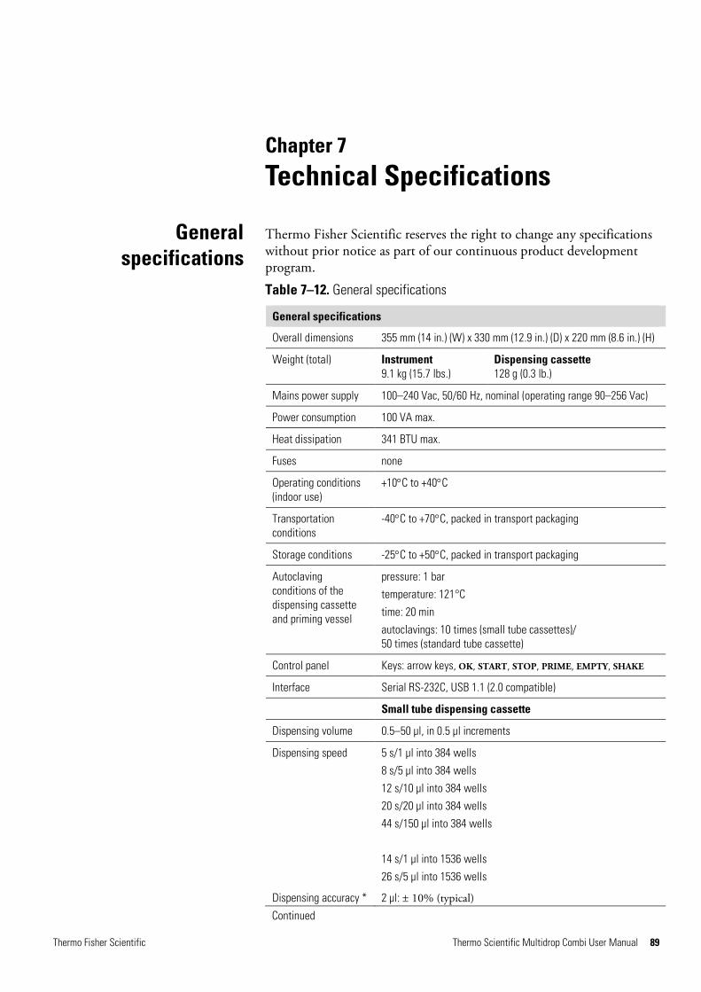
Thermo Fisher Scientific Thermo Scientific Multidrop Combi User Manual 89
Chapter 7 Technical Specifications
Thermo Fisher Scientific reserves the right to change any specifications without prior notice as part of our continuous product development program.
Table 7–12. General specifications
General specifications
Overall dimensions 355 mm (14 in.) (W) x 330 mm (12.9 in.) (D) x 220 mm (8.6 in.) (H)
Weight (total) Instrument 9.1 kg (15.7 lbs.)
Dispensing cassette 128 g (0.3 lb.)
Mains power supply 100–240 Vac, 50/60 Hz, nominal (operating range 90–256 Vac)
Power consumption 100 VA max.
Heat dissipation 341 BTU max.
Fuses none
Operating conditions (indoor use)
+10°C to +40°C
Transportation conditions
-40°C to +70°C, packed in transport packaging
Storage conditions -25°C to +50°C, packed in transport packaging
Autoclaving conditions of the dispensing cassette and priming vessel
pressure: 1 bar
temperature: 121°C
time: 20 min
autoclavings: 10 times (small tube cassettes)/ 50 times (standard tube cassette)
Control panel Keys: arrow keys, OK, START, STOP, PRIME, EMPTY, SHAKE
Interface Serial RS-232C, USB 1.1 (2.0 compatible)
Small tube dispensing cassette
Dispensing volume 0.5–50 µl, in 0.5 µl increments
Dispensing speed 5 s/1 µl into 384 wells
8 s/5 µl into 384 wells
12 s/10 µl into 384 wells
20 s/20 µl into 384 wells
44 s/150 µl into 384 wells
14 s/1 µl into 1536 wells
26 s/5 µl into 1536 wells
Dispensing accuracy * 2 µl: ± 10% (typical)
General specifications
Continued

Technical Specifications Safety specifications
90 Thermo Scientific Multidrop Combi User Manual Thermo Fisher Scientific
General specifications 10 µl: ± 5% (typical) > 10 µl: ± 5% (typical)
Dispensing precision * 0.5 µl: CV ≤ 10%
2 µl: CV ≤ 5%
10 µl: CV ≤ 3%
> 10 µl: CV ≤ 3%
Standard tube dispensing cassette
Dispensing volume 5–2500 µl, in 5 µl increments
Dispensing speed 3 s/10 µl into 96 wells
4 s/20 µl into 96 wells
10 s/100 µl into 96 wells
20 s/300 µl into 96 wells
5 s/5 µl into 384 wells
6 s/10 µl into 384 wells
9 s/20 µl into 384 wells
Dispensing accuracy * 5 µl: ± 3% (typical) 20 µl: ± 2% (typical) 100 µl: ± 1% (typical) > 100 µl: ± 1% (typical)
Dispensing precision * 5 µl: CV ≤ 10%
20 µl: CV ≤ 1.5%
100 µl: CV ≤ 1%
> 100 µl: CV ≤ 1%
* Dispensing accuracy and precision are valid at 22°C ± 2°C with deionized distilled water.
This section describes the safety specifications for the Multidrop Combi instrument.
The instrument is safe to operate with the covers fitted and these must not be removed during operation. The covers protect the user from live parts and they should only be removed after switching the instrument off and disconnecting the mains supply cable, and only by suitably qualified maintenance and repair personnel.
Warning The instrument uses voltages dangerous for human beings. Before removing any covers, disconnect the instrument from the power supply. s
Multidrop Combi bears the following markings:
Type 836
100–240 Vac, 50/60 Hz, 100 VA
CE mark
CSA monogram
Safety specifications
Live parts
In conformity with the
requirements
Cont.
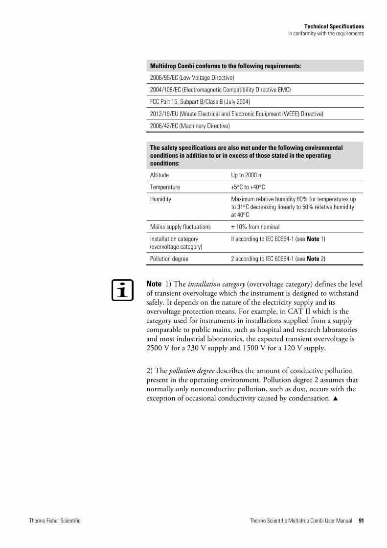
Technical Specifications In conformity with the requirements
Thermo Fisher Scientific Thermo Scientific Multidrop Combi User Manual 91
Multidrop Combi conforms to the following requirements:
2006/95/EC (Low Voltage Directive)
2004/108/EC (Electromagnetic Compatibility Directive EMC)
FCC Part 15, Subpart B/Class B (July 2004)
2012/19/EU (Waste Electrical and Electronic Equipment (WEEE) Directive)
2006/42/EC (Machinery Directive)
The safety specifications are also met under the following environmental conditions in addition to or in excess of those stated in the operating conditions:
Altitude Up to 2000 m
Temperature +5°C to +40°C
Humidity Maximum relative humidity 80% for temperatures up to 31°C decreasing linearly to 50% relative humidity at 40°C
Mains supply fluctuations ± 10% from nominal
Installation category (overvoltage category)
II according to IEC 60664-1 (see Note 1)
Pollution degree 2 according to IEC 60664-1 (see Note 2)
Note 1) The installation category (overvoltage category) defines the level of transient overvoltage which the instrument is designed to withstand safely. It depends on the nature of the electricity supply and its overvoltage protection means. For example, in CAT II which is the category used for instruments in installations supplied from a supply comparable to public mains, such as hospital and research laboratories and most industrial laboratories, the expected transient overvoltage is 2500 V for a 230 V supply and 1500 V for a 120 V supply.
2) The pollution degree describes the amount of conductive pollution present in the operating environment. Pollution degree 2 assumes that normally only nonconductive pollution, such as dust, occurs with the exception of occasional conductivity caused by condensation. s
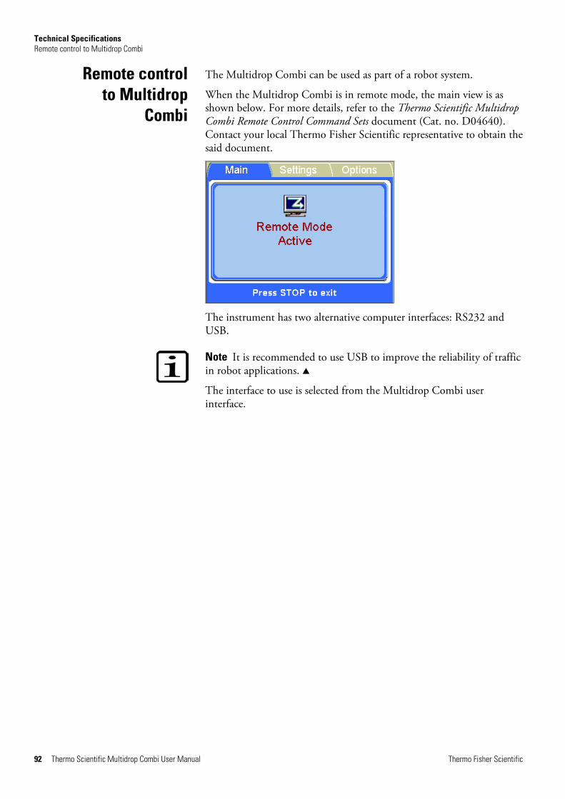
Technical Specifications Remote control to Multidrop Combi
92 Thermo Scientific Multidrop Combi User Manual Thermo Fisher Scientific
The Multidrop Combi can be used as part of a robot system.
When the Multidrop Combi is in remote mode, the main view is as shown below. For more details, refer to the Thermo Scientific Multidrop Combi Remote Control Command Sets document (Cat. no. D04640). Contact your local Thermo Fisher Scientific representative to obtain the said document.
The instrument has two alternative computer interfaces: RS232 and USB.
Note It is recommended to use USB to improve the reliability of traffic in robot applications. s
The interface to use is selected from the Multidrop Combi user interface.
Remote control to Multidrop
Combi
Thermo Fisher Scientific Thermo Scientific Multidrop Combi User Manual 93
Chapter 8 Frequently Asked Questions
Q: How many times can the Multidrop Combi dispensing cassettes be autoclaved?
A: Either 10 times (small tube cassettes, Cat. no. 2407390 and 2407395) or 50 times (standard tube cassette, Cat. no. 24072670).
Q: Can the dispensing cassettes of the Multidrop Combi be used in the Multidrop 384 and Thermo Scientific Multidrop DW?
A: Yes, the dispensing cassettes are interchangeable. The standard tube cassette (Cat. no. 24072670) can be used in the Multidrop 384 and Multidrop DW. The small tube cassettes (Cat. no. 2407390 and 2407395) can be used in the Multidrop Micro.
Q: Can the Dispensing cassette, machined covers (Cat. no. 24070300) be used in the Multidrop Combi?
A: No, it cannot be used.
Q: How many times can the Multidrop Combi dispensing cassettes be autoclaved?
A: Either 10 times (small tube cassettes, Cat. no. 2407390 and 2407395) or 50 times (standard tube cassette, Cat. no. 24072670).
Q: Can the dispensing cassettes with the SMART option be autoclaved?
A: Yes, as many times as the cassettes without the RFID tag.
Q: What are the autoclaving conditions for the dispensing cassettes?
A: The autoclaving conditions are as follows: 1 bar pressure at 121°C for 20 minutes.
Q&As

Frequently Asked Questions Q&As
94 Thermo Scientific Multidrop Combi User Manual Thermo Fisher Scientific
Q: What is the dead volume of the dispensing cassettes of the Multidrop Combi with 40 cm tubing?
A: The dead volume is about 1.0 ml with the small tube cassettes. However, the dead volume is < 7 ml for the standard tube cassette. Note that it is possible to empty the reagent back to the original reservoir to avoid losing expensive reagent.
Q: Does the dispensing cassette of the Multidrop Combi include a calibration certificate?
A: Yes, all dispensing cassettes include a factory calibration report.
Q: What liquid is recommended to be used for washing the Multidrop Combi tubes?
A: It is recommended that you use deionized distilled water and/or detergent solutions, for example, 0.2–1% Tween followed by deionized distilled water.
Q: When do you have to calibrate the dispensing cassettes of the Multidrop Combi?
A: It is recommended that you recalibrate at least monthly, depending on the frequency of use and the liquids used.
Q: Can the dispensing cassettes of the Multidrop Combi be recalibrated?
A: Yes, they can.
Q: What is the tip inner diameter of the dispensing cassettes of the Multidrop Combi?
A: The tip inner diameter is either 0.22 mm (Small tube plastic tip dispensing cassette, Cat. no. 24073290, and Small tube metal tip dispensing cassette, Cat. no. 24073295), or 0.5 mm (Standard tube dispensing cassette, Cat. no. 24072670).
Q: Do particles in the reagent affect dispensing?
A: Possibly. It is recommended that you ensure that there are no particles > 50 µm in the reagent to avoid blockage of the tips, especially when working with small tube cassettes.
Frequently Asked Questions Q&As
Thermo Fisher Scientific Thermo Scientific Multidrop Combi User Manual 95
Q: What materials come into contact with liquids to be dispensed?
A: The Small tube plastic tip dispensing cassette, Cat. no. 24073290, and the Standard tube dispensing cassette, Cat. no. 24072670, are made of: PEEK, silicone, and PP (polypropylene).
The Small tube metal tip dispensing cassette, Cat. no. 24073295, is made of: PEEK, silicone, ruby, and stainless steel.
Q: What should you do if the liquid foams during dispensing?
A: Some liquids foam more easily than others. One option is to reduce the pump rotor speed. There are three dispensing speeds available: High, Med (medium), and Low.
Q: Do you need specific plate adapters for the Multidrop Combi?
A: No, the Multidrop Combi has a fixed plate adapter and does not use any external plate adapters.
Q: What is the material of the Multidrop Combi priming vessel?
A: The Multidrop Combi priming vessel (Cat. no. N05640) is made of blue polypropylene (PP).
Q: Can the Multidrop Combi priming vessel be autoclaved?
A: Yes, it can be autoclaved.
Q: Where can you see the Multidrop Combi internal software version number?
A: When the instrument is powered on, the version number only appears on the bottom of the screen during the startup animation.
Q: Can the SMART cassettes with RFID tags be used with the standard Multidrop Combi without SMART option or vice versa?
A: Yes, but then the calibration data cannot be viewed and the information about the cassette is not updated. Also standard cassettes can be used with the Multidrop Combi with SMART option.
Q: What is the tubing length of standard tube dispensing cassettes and small tube dispensing cassettes?
A: The tubing length is 40 cm.
Frequently Asked Questions Q&As
96 Thermo Scientific Multidrop Combi User Manual Thermo Fisher Scientific
Q: What is the tubing length of Long standard tube dispensing cassettes and Long small tube dispensing cassettes?
A: The tubing length is 200 cm.
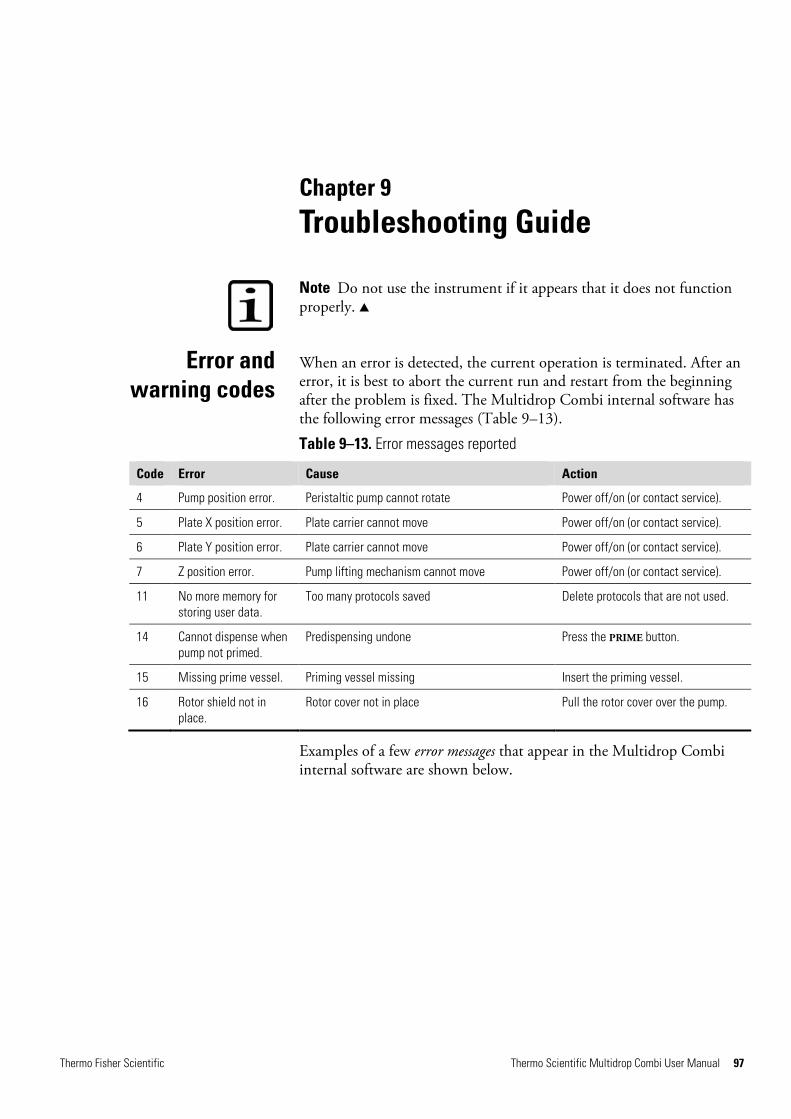
Thermo Fisher Scientific Thermo Scientific Multidrop Combi User Manual 97
Chapter 9 Troubleshooting Guide
Note Do not use the instrument if it appears that it does not function properly. s
When an error is detected, the current operation is terminated. After an error, it is best to abort the current run and restart from the beginning after the problem is fixed. The Multidrop Combi internal software has the following error messages (Table 9–13).
Table 9–13. Error messages reported
Code Error Cause Action
4 Pump position error. Peristaltic pump cannot rotate Power off/on (or contact service).
5 Plate X position error. Plate carrier cannot move Power off/on (or contact service).
6 Plate Y position error. Plate carrier cannot move Power off/on (or contact service).
7 Z position error. Pump lifting mechanism cannot move Power off/on (or contact service).
11 No more memory for storing user data.
Too many protocols saved Delete protocols that are not used.
14 Cannot dispense when pump not primed.
Predispensing undone Press the PRIME button.
15 Missing prime vessel. Priming vessel missing Insert the priming vessel.
16 Rotor shield not in place.
Rotor cover not in place Pull the rotor cover over the pump.
Examples of a few error messages that appear in the Multidrop Combi internal software are shown below.
Error and warning codes
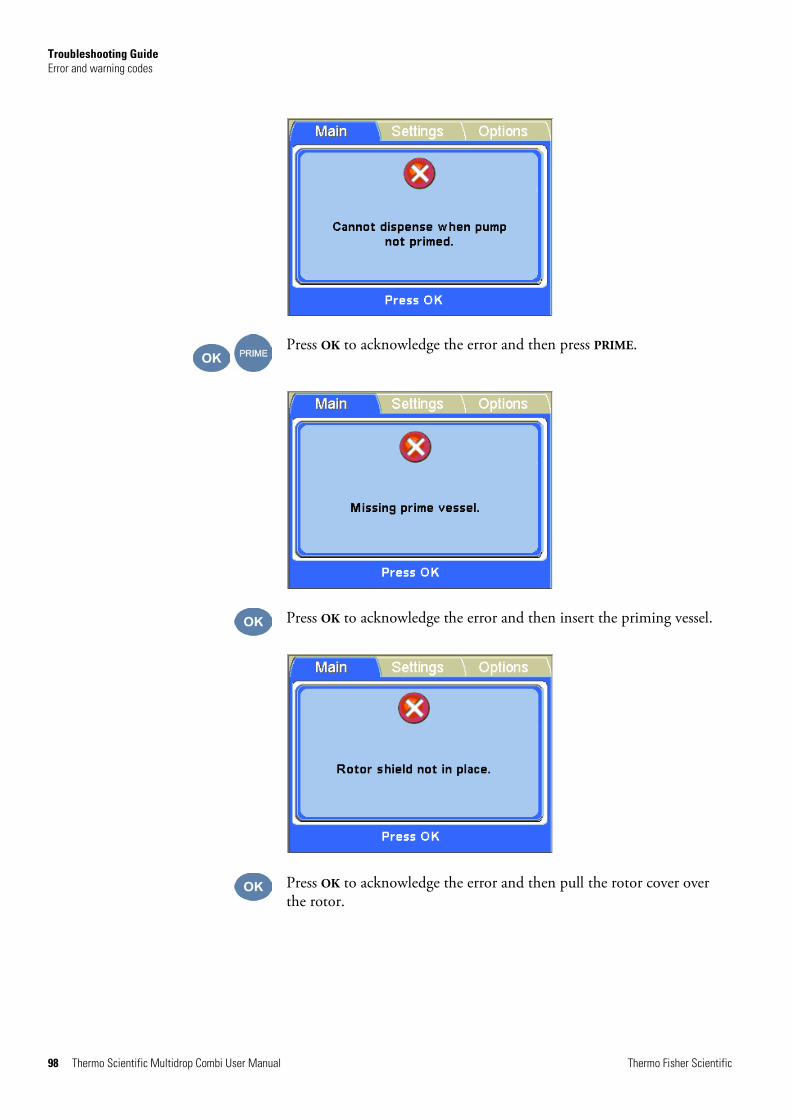
Troubleshooting Guide Error and warning codes
98 Thermo Scientific Multidrop Combi User Manual Thermo Fisher Scientific
Press OK to acknowledge the error and then press PRIME.
Press OK to acknowledge the error and then insert the priming vessel.
Press OK to acknowledge the error and then pull the rotor cover over the rotor.

Troubleshooting Guide Hazards
Thermo Fisher Scientific Thermo Scientific Multidrop Combi User Manual 99
An example of a warning message that appears in the main view of the Multidrop Combi internal software is shown below.
Press OK to acknowledge the warning and continue dispensing or press STOP to cancel and then reselect the dispensing volume.
This instrument is designed to provide full user protection. When correctly installed, operated and maintained, the instrument will present no hazards to the user.
The following recommendations are given to ascertain added user safety.
Ensure that the mains supply cable supplied with the unit is always used.
The mains plug should only be inserted into a socket outlet provided with a protective ground contact.
Warning There are no user-replaceable parts inside the instrument. The user should not remove the cover from the Multidrop Combi. s
The same precautions applicable when using any electrical equipment should be observed with this instrument. Do not touch switches or electrical outlets with wet hands. Switch the instrument off before disconnecting it from the mains supply.
The dispensing cassette is a free-moving mechanical device controlled by the instrument and not directly by the operator. It is designed for “hands-off” operation and should be used as such. Never reach into the work space, while the instrument is performing a dispensing cycle.
Hazards
Electrical
Mechanical

Troubleshooting Guide Hazards
100 Thermo Scientific Multidrop Combi User Manual Thermo Fisher Scientific
If it is necessary to stop the operation of the equipment, press the STOP button on the control panel.
Infectious samples and corrosive fluids are commonly used with this equipment. The “hands-off” nature of the system allows the user to dispense into the reaction wells without getting into direct contact with these fluids. However, the wells that have been in contact with potentially hazardous fluids must be handled with utmost care. Always wear hand and eye protections as well as corrosive resistant laboratory coats.
Warning Observe normal laboratory procedures for handling potentially hazardous samples. s
Whenever it is likely that the protection against safety hazards has been impaired, make the instrument inoperative and secure against any unintended operation.
The protection is likely to be impaired if, for example, the instrument:
l Shows visible damage.
l Fails to perform the intended functions.
l Has been subjected to prolonged storage under unfavorable conditions.
l Has been subjected to severe transport stresses.
Environmental
Defects and abnormal stresses

Thermo Fisher Scientific Thermo Scientific Multidrop Combi User Manual 101
Chapter 10 Ordering Information
Contact your local Thermo Fisher Scientific representative for ordering and service information.
Table 10–14. Instrument catalog number
Code Instrument / System
5840300 Multidrop Combi, 100−240 V, 50/60 Hz
5840310 Multidrop Combi with SMART 2 option, 100−240 V, 50/60 Hz
Table 10–15. Codes for dispensing cassettes
Code Item
STANDARD TUBE DISPENSING CASSETTES
24072670 Standard tube dispensing cassette
24072671 Standard tube dispensing cassette 5-pack
24072671S Standard tube dispensing cassette 5-pack, Irradiated
24072672 Standard tube dispensing cassette 10-pack
24072677 Long standard tube dispensing cassette
SMALL TUBE DISPENSING CASSETTES
24073290 Small tube plastic tips dispensing cassette
24073291 Small tube plastic tips dispensing cassette 5-pack
24073291S Small tube plastic tip dispensing cassette 5-pack, Irradiated
24073295 Small tube metal tip dispensing cassette
24073296 Small tube metal tip dispensing cassette 5-pack
24073296S Small tube metal tip dispensing cassette 5-pack, Irradiated
24073293 Long small tube plastic tip dispensing cassette
24073298 Long small tube metal tip dispensing cassette
SMART 2 DISPENSING CASSETTES FOR MULTIDROP COMBI SMART 2 INSTRUMENTS WITH SERIAL NUMBER 836-2846SM ONWARDS
N15133 SMART 2 small tube plastic tip dispensing cassette, new RFID tag
N15134 SMART 2 small tube plastic tip dispensing cassette 5-pack, new RFID tag
N15135 SMART 2 small tube metal tip dispensing cassette, new RFID tag
N15136 SMART 2 small tube metal tip dispensing cassette 5-pack, new RFID
Multidrop Combi
Dispensing cassettes
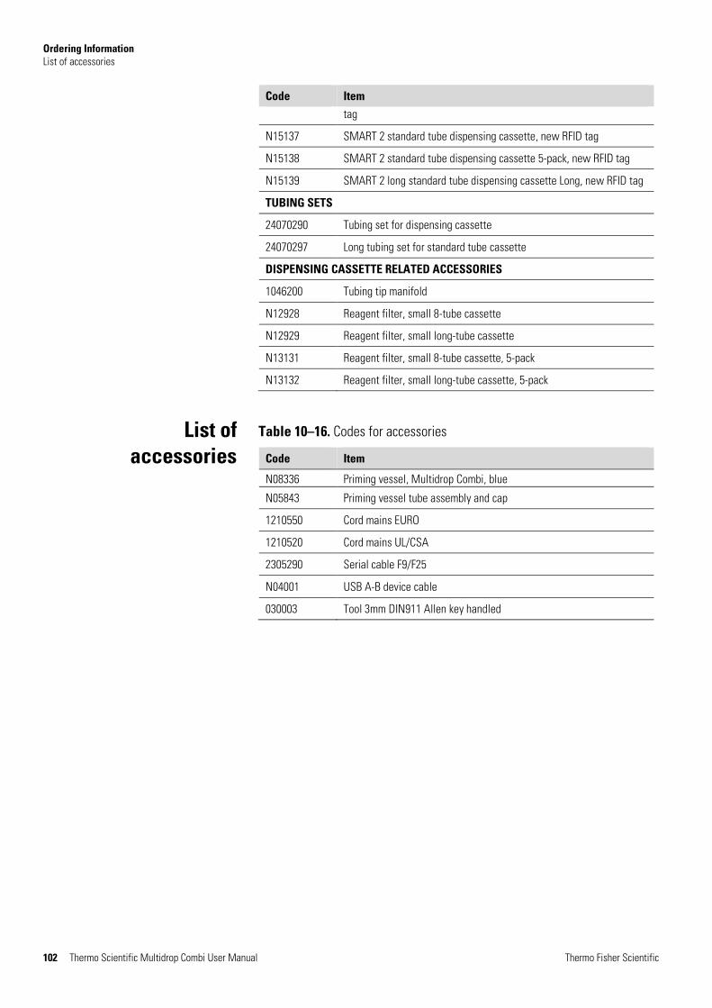
Ordering Information List of accessories
102 Thermo Scientific Multidrop Combi User Manual Thermo Fisher Scientific
Code Item tag
N15137 SMART 2 standard tube dispensing cassette, new RFID tag
N15138 SMART 2 standard tube dispensing cassette 5-pack, new RFID tag
N15139 SMART 2 long standard tube dispensing cassette Long, new RFID tag
TUBING SETS
24070290 Tubing set for dispensing cassette
24070297 Long tubing set for standard tube cassette
DISPENSING CASSETTE RELATED ACCESSORIES
1046200 Tubing tip manifold
N12928 Reagent filter, small 8-tube cassette
N12929 Reagent filter, small long-tube cassette
N13131 Reagent filter, small 8-tube cassette, 5-pack
N13132 Reagent filter, small long-tube cassette, 5-pack
Table 10–16. Codes for accessories
Code Item
N08336 Priming vessel, Multidrop Combi, blue
N05843 Priming vessel tube assembly and cap
1210550 Cord mains EURO
1210520 Cord mains UL/CSA
2305290 Serial cable F9/F25
N04001 USB A-B device cable
030003 Tool 3mm DIN911 Allen key handled
List of accessories
Thermo Fisher Scientific Thermo Scientific Multidrop Combi User Manual 103
Chapter 11 References
Editorial (2004): Multidrop bulk reagent dispenser family from Thermo Electron; precise dispensing in the microliter area allowing assay miniaturization. Innovations in Pharmaceutical Technology 4 (14), 36.
Falconer M. et al. (2002): High-Throughput Screening for Ion Channel Modulators. Journal of Biomolecular Screening 7 (5), 460–465.
Kiger A. A. et al. (2003): A functional genomic analysis of cell morphology using RNA interference. Journal of Biology 2, 27.
Tanaka M. et al. (2005): An unbiased cell morphology-based screen for new, biologically active small molecules. PLoS Biology 3 (5), e128.
Yarrow J. C. et al. (2004): A high-throughput cell migration assay using scratch wound healing, a comparison of image-based readout methods. BMC Biotechnology 4, 21.
Literature
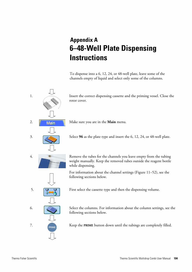
Thermo Fisher Scientific Thermo Scientific Multidrop Combi User Manual 104
Appendix A 6–48-Well Plate Dispensing Instructions
To dispense into a 6, 12, 24, or 48-well plate, leave some of the channels empty of liquid and select only some of the columns.
1.
Insert the correct dispensing cassette and the priming vessel. Close the rotor cover.
2.
Make sure you are in the Main menu.
3.
Select 96 as the plate type and insert the 6, 12, 24, or 48-well plate.
4.
Remove the tubes for the channels you leave empty from the tubing weight manually. Keep the removed tubes outside the reagent bottle while dispensing.
For information about the channel settings (Figure 11–52), see the following sections below.
5.
First select the cassette type and then the dispensing volume.
6.
Select the columns. For information about the column settings, see the following sections below.
7.
Keep the PRIME button down until the tubings are completely filled.
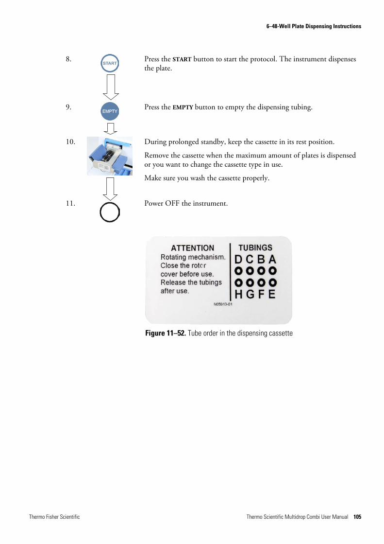
6–48-Well Plate Dispensing Instructions
Thermo Fisher Scientific Thermo Scientific Multidrop Combi User Manual 105
8.
Press the START button to start the protocol. The instrument dispenses the plate.
9.
Press the EMPTY button to empty the dispensing tubing.
10.
During prolonged standby, keep the cassette in its rest position.
Remove the cassette when the maximum amount of plates is dispensed or you want to change the cassette type in use.
Make sure you wash the cassette properly.
11.
Power OFF the instrument.
Figure 11–52. Tube order in the dispensing cassette
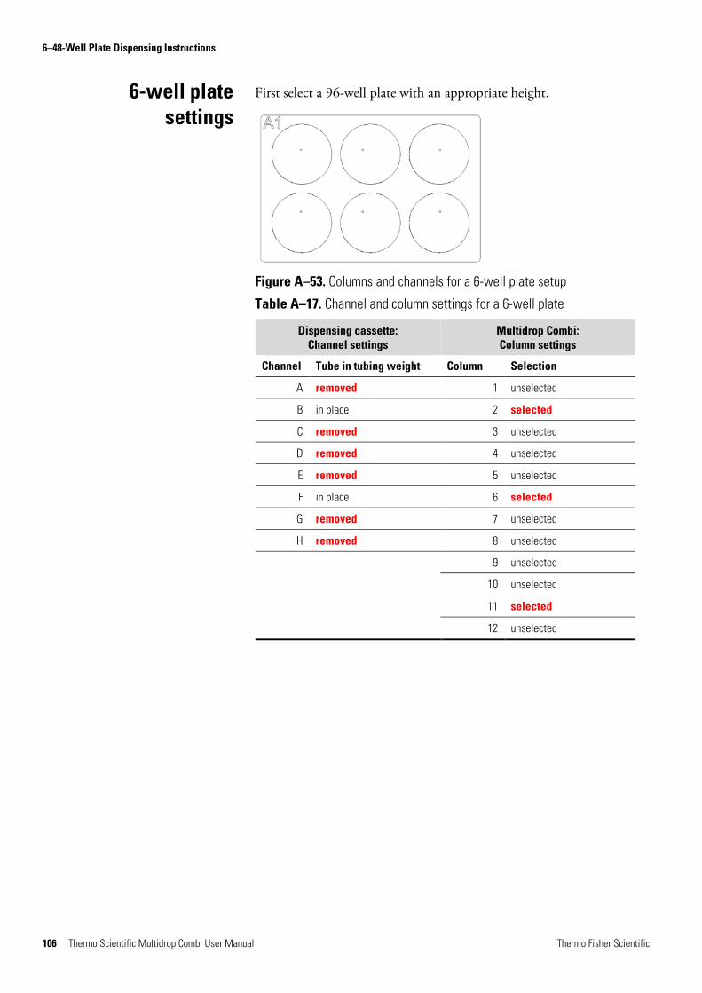
6–48-Well Plate Dispensing Instructions
106 Thermo Scientific Multidrop Combi User Manual Thermo Fisher Scientific
First select a 96-well plate with an appropriate height.
Figure A–53. Columns and channels for a 6-well plate setup
Table A–17. Channel and column settings for a 6-well plate
Dispensing cassette: Channel settings
Multidrop Combi: Column settings
Channel Tube in tubing weight Column Selection
A removed 1 unselected
B in place 2 selected
C removed 3 unselected
D removed 4 unselected
E removed 5 unselected
F in place 6 selected
G removed 7 unselected
H removed 8 unselected
9 unselected
10 unselected
11 selected
12 unselected
6-well plate settings

6–48-Well Plate Dispensing Instructions
Thermo Fisher Scientific Thermo Scientific Multidrop Combi User Manual 107
First select a 96-well plate with an appropriate height.
Figure A–54. Columns and channels for a 12-well plate setup
Table A–18. Channel and column settings for a 12-well plate
Dispensing cassette: Channel settings
Multidrop Combi: Column settings
Channel Tube in tubing weight Column Selection
A removed 1 unselected
B in place 2 selected
C removed 3 unselected
D in place 4 unselected
E removed 5 selected
F removed 6 unselected
G in place 7 unselected
H removed 8 selected
9 unselected
10 unselected
11 selected
12 unselected
12-well plate settings
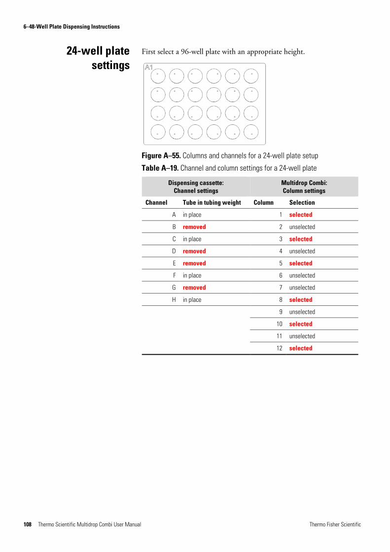
6–48-Well Plate Dispensing Instructions
108 Thermo Scientific Multidrop Combi User Manual Thermo Fisher Scientific
First select a 96-well plate with an appropriate height.
Figure A–55. Columns and channels for a 24-well plate setup
Table A–19. Channel and column settings for a 24-well plate
Dispensing cassette: Channel settings
Multidrop Combi: Column settings
Channel Tube in tubing weight Column Selection
A in place 1 selected
B removed 2 unselected
C in place 3 selected
D removed 4 unselected
E removed 5 selected
F in place 6 unselected
G removed 7 unselected
H in place 8 selected
9 unselected
10 selected
11 unselected
12 selected
24-well plate settings

6–48-Well Plate Dispensing Instructions
Thermo Fisher Scientific Thermo Scientific Multidrop Combi User Manual 109
First select a 96-well plate with an appropriate height.
Figure A–56. Columns and channels for a 48-well plate setup
Table A–20. Channel and column settings for a 48-well plate
Dispensing cassette: Channel settings
Multidrop Combi: Column settings
Channel Tube in tubing weight Column Selection
A in place 1 selected
B in place 2 unselected
C removed 3 selected
D in place 4 selected
E in place 5 unselected
F removed 6 selected
G in place 7 selected
H in place 8 unselected
9 selected
10 selected
11 unselected
12 selected
48-well plate settings
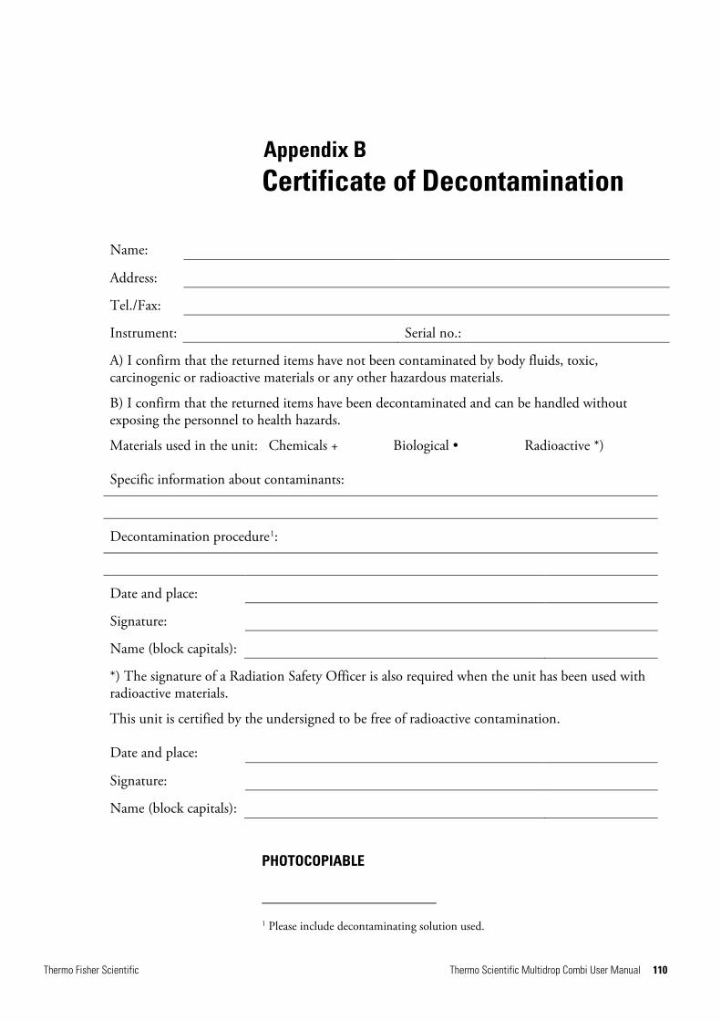
Thermo Fisher Scientific Thermo Scientific Multidrop Combi User Manual 110
Appendix B Certificate of Decontamination
Name:
Address:
Tel./Fax:
Instrument: Serial no.:
A) I confirm that the returned items have not been contaminated by body fluids, toxic, carcinogenic or radioactive materials or any other hazardous materials.
B) I confirm that the returned items have been decontaminated and can be handled without exposing the personnel to health hazards.
Materials used in the unit: Chemicals + Biological • Radioactive *)
Specific information about contaminants:
Decontamination procedure1:
Date and place:
Signature:
Name (block capitals):
*) The signature of a Radiation Safety Officer is also required when the unit has been used with radioactive materials.
This unit is certified by the undersigned to be free of radioactive contamination.
Date and place:
Signature:
Name (block capitals):
PHOTOCOPIABLE
1 Please include decontaminating solution used.

Thermo Fisher Scientific Thermo Scientific Multidrop Combi User Manual 111
Glossary
antenna The tag antenna is the conductive element that enables the tag to send and receive data. The RF energy from the reader antenna is “harvested” by the antenna and used to power up the microchip, which then changes the electrical load on the antenna to reflect back its own signals. See RFID and RFID tag.
back flush (empty) The operation of discharging the contents of the tubing of fluid.
calibration screw The eight screws under the calibration screw cover that will adjust the length of the tube during calibration of the dispensing cassette (Figure 6–50).
CE marking "Conformité Européene" = European Conformity. CE Marking on a product is a manufacturer's declaration that the product complies with the essential requirements of the relevant European health, safety and environmental protection legislations, the product may be legally placed on the market and thus the CE Marking ensures the free movement of the product within EU.
decontamination Removal or neutralization of radiologic, bacteriological, chemical or other contamination.
dispense To distribute (pipette) liquid into the wells of the preselected strips or microplate.
dispensing cassette The dispensing cassette contains eight individual tubes. The dispensing cassette is detachable and disposable.
dispensing height The tip position on top of the microplate. The distance between the bottom surface of the plate carrier to the tip of the dispensing tip (Table 4–3).
EIA Enzyme immunoassay.
emulation mode Running mode imitating the function of Multidrop 384 or Multidrop Micro.
EN European Norm.
EU European Union.
home position The plate carrier is positioned to the furthest right of the transfer rails.
IEC International Electrotechnical Commission.
PEEK Abbreviation for polyetheretherketone. It is a plastic material.
predispense The operation of filling a pump intake with fluid to expel the air.
predispensing (priming) Completely filling the dispenser tubing with bubble-free fluid to allow sustained, reproducible dispensing action. The air in an unpredispensed line acts as a spring, adversely affecting accuracy and precision.
remote control Running mode allowing a remote computer to operate the dispenser.
RFID Radio frequency identification, or RFID, is an automatic identification method, relying on storing and remotely retrieving data using devices called RFID tags or transponders. An RFID tag is a small object that can be attached to or incorporated into a product. RFID tags contain silicon chips and antennas to enable them to receive and respond to radiofrequency queries from an RFID transceiver. See antenna and RFID tag.
RFID tag A microchip attached to an antenna that is packaged in a way that it can be applied to an object. The tag picks up and sends signals to a reader. The tag contains information, such as a serial number and parameters related to the product where the tag is attached. Tags come in many forms, such smart labels that can have a barcode printed on it, or the tag can simply be mounted inside a carton or embedded in plastic. See antenna and RFID.

Glossary: tension limiting wire
112 Thermo Scientific Multidrop Combi User Manual Thermo Fisher Scientific
tension limiting wires The tension limiting wires (Figure 4–10 and Figure 5–32) are designed to prevent the user from pulling the tubes too much as excessive tension may damage the tubes
or change the calibration of the dispensing cassette.
USB Universal serial bus.

Thermo Fisher Scientific Thermo Scientific Multidrop Combi User Manual 113
Index
1 1536-well plates, 13, 14, 48, 60
3 384-well plates, 13, 14, 47, 59, 60
6 6 – 48-well plate dispensing instructions, 104
9 96-well plates, 14, 47, 60, 78, 79, 82, 83, 84
A accessories, 6, 18, 19, 102 accuracy verification, 78, 79, 80, 81, 84 advantages of using Multidrop Combi, 15 alibration, 57 antenna, 59, 111 application, 2 autoclaving the dispensing cassette, 68
B backflush, 15, 30, 111
C calibration, 26, 29, 33, 57, 58, 59, 70, 73, 74, 75, 76, 78, 80,
84, 85, 86, 87, 88, 94, 95, 111, 112 date, 87 screw, 70, 73, 74, 75, 76, 86, 87, 88, 111
CE Marking, 111 cleaning the tips, 67 column selection, 14, 33, 39, 40 command set, 55 computer interface, 33, 54, 92 contrast and buzzer, 33, 57 control panel, 30, 89, 100
D dead volume, 94 decontamination, 61, 62, 63, 64, 65, 66, 110, 111 default, 37, 38, 39, 42, 43, 44, 45, 46, 47, 53
protocols, 53 values, 37
deleting a protocol, 52, 97 dispensing, 3, 13, 14, 15, 19, 22, 23, 24, 25, 26, 27, 28, 29,
30, 33, 34, 35, 36, 37, 38, 39, 40, 41, 42, 43, 44, 45, 47, 48, 59, 60, 61, 62, 63, 64, 66, 67, 68, 69, 70, 71, 72, 73, 74, 75, 76, 77, 78, 79, 80, 81, 82, 83, 84, 85, 86, 89, 90, 93, 94, 95, 97, 99, 100, 101, 103, 104, 105, 106, 107, 108, 109, 111, 112 accuracy, 89, 90 direction, 33, 47 height, 33, 37, 44, 45, 111 offset, 33, 37, 44 parameters, 35, 36, 79, 85 precision, 90 range, 24 speed, 15, 33, 38, 42, 43, 83, 89, 90, 95 volume, 34, 35, 37, 38, 39, 40, 41, 79, 84, 85, 89, 90, 99,
104 disposal of, 63, 65, 77
dispensing cassette, 77 instrument, 65 materials, 63
disposal of dispensing cassette, 77 disposal of instrument, 65 disposal of materials, 63
E editing a protocol, 33, 36, 42, 49, 50, 51, 52, 53 EIA, 63, 111 empty, 30, 34, 40, 60, 61, 63, 65, 66, 67, 78, 83, 86, 89,
104, 105, 111 emulation mode, 111 EN, 111 environmental requirements, 19 error messages, 97 EU, 111
114 Thermo Scientific Multidrop Combi User Manual Thermo Fisher Scientific
G glossary, 59, 111 guidelines for use, 6
H hazards, 4, 62, 99, 100, 110 home position, 14, 22, 30, 47 how to install the Multiskan FC, 91
I icons, 32, 33 IEC, 111 info text, 31, 32, 59 installation, 3, 18, 19, 20, 22, 25, 65, 70, 79, 82, 84, 91
category, 91 intended use, 3, 13 internal software, 3, 30, 36, 95, 97, 99
K keyboard and display, 17, 30, 89
M maintenance, 3, 6, 62, 65, 66, 90 markings, 111
N navigating, 30, 31, 32, 35
O operational check, 22
P packing instructions, 18, 65 packing list, 18 plate, 13, 14, 15, 21, 22, 23, 30, 33, 34, 35, 36, 37, 38, 39,
42, 44, 45, 46, 47, 48, 52, 56, 57, 59, 60, 63, 65, 69, 72, 78, 79, 80, 81, 82, 83, 84, 85, 86, 95, 97, 104, 105, 106, 107, 108, 109, 111 carrier, 14, 21, 22, 23, 44, 47, 48, 65, 79, 83, 97, 111 type, 33, 34, 35, 36, 37, 38, 39, 42, 44, 45, 46, 47, 48,
52, 56, 57, 79, 85, 104 precalibration, 75, 76 precautions and limitations, 19 precision verification, 78, 80, 82
predispense, 22, 30, 35, 46, 66, 83, 111 predispensing, 33, 46, 64, 66, 97, 111
volume, 33, 46 prime, 22, 30, 33, 34, 35, 46, 48, 64, 66, 67, 79, 83, 86, 89,
97, 98, 104, 111 priming vessel, 15, 22, 23, 34, 48, 62, 63, 65, 79, 82, 85, 86,
89, 95, 97, 98, 102, 104 priming volume, 33, 46 principle of operation, 13, 15 protocol settings, 42 pump, 13, 14, 21, 22, 25, 26, 27, 29, 30, 43, 44, 45, 47, 48,
59, 95, 97, 111 lifting mechanism, 14, 22, 47, 97 rotor, 22, 25, 26, 27, 29, 34, 59, 60, 79, 82, 85, 95, 97,
98, 104 speed, 15, 33, 38, 42, 43, 83, 89, 90, 95
R reagent pretreatment, 24 recalibrating the dispensing cassette, 78 releasing the transport lock, 20 remote control, 15, 55, 92, 111 remote mode, 33, 55, 92 rest position, 28, 29, 34, 60, 61, 66, 67, 105 RFID, 59, 93, 95, 111
tag, 20, 21, 59, 93, 95, 111 robotic, 15 rotor, 22, 25, 27, 29, 34, 59, 60, 79, 82, 85, 95, 97, 98, 104
cover, 22, 29, 34, 59, 79, 82, 85, 97, 98, 104 needles, 27 shaft, 25, 27
running a protocol, 48
S saving a protocol, 33, 37, 42, 49, 50, 51, 52, 57, 70 selecting a protocol, 51 selecting columns, 14, 33, 39, 79, 85 service, 61, 62, 65, 97, 101
contracts, 62, 65 shutdown, 60, 67 specifications, 3, 65, 66, 80, 89, 90, 91 speed, 15, 38, 43, 83, 89, 90, 95 startup, 33, 53, 55, 56, 95 start-up protocol, 33, 53, 55, 56 symbols and markings, 4, 5, 6
Thermo Fisher Scientific Thermo Scientific Multidrop Combi User Manual 115
T technical specifications, 80, 89 tension limiting wires, 25, 26, 27, 70, 71, 73, 112 tip, 24, 25, 27, 28, 38, 67, 68, 69, 70, 94, 95, 111
manifold, 69, 70 material, 24
transport, 18, 20, 21, 64, 65, 89, 100 lock, 20, 21, 65 package, 18, 64
troubleshooting, 22, 97 tubing, 23, 24, 27, 28, 34, 48, 60, 67, 68, 69, 70, 71, 72, 73,
74, 76, 83, 94, 104, 105, 106, 107, 108, 109, 111 material, 24
U unpacking, 18
USB, 15, 54, 89, 92, 102, 112 using the keyboard and display, 17, 30, 89, 100
V volume, 13, 15, 33, 35, 37, 38, 40, 41, 46, 78, 79, 80, 81,
82, 83, 84, 85, 89, 90, 94, 99, 104 conversion factor, 78, 80 range, 13, 15, 38, 46
W warning messages, 99 warranty, 18 washing the dispensing cassette, 66 WEEE, 4, 91

116 Thermo Scientific Multidrop Combi User Manual Thermo Fisher Scientific

Thermo Fisher Scientific Thermo Scientific Multidrop Combi User Manual 117
Notes

118 Thermo Scientific Multidrop Combi User Manual Thermo Fisher Scientific
Notes

Thermo Fisher Scientific Thermo Scientific Multidrop Combi User Manual 119
Notes