
Murelle -GB - SIME
38
INSTALLER INSTRUCTIONS CONTENTS 1 DESCRIPTION OF THE BOILER . . . . . . . . . . . . . . . . . . . . . . . . . . . . . . . . . . . . . . . . . . . . . . . . . . . . . . . . . . . . . . . pag. 108 2 INSTALLATION . . . . . . . . . . . . . . . . . . . . . . . . . . . . . . . . . . . . . . . . . . . . . . . . . . . . . . . . . . . . . . . . . . . . . . . . . . . . . . pag. 114 3 CHARACTERISTICS . . . . . . . . . . . . . . . . . . . . . . . . . . . . . . . . . . . . . . . . . . . . . . . . . . . . . . . . . . . . . . . . . . . . . . . . . pag. 127 4 USE AND MAINTENANCE . . . . . . . . . . . . . . . . . . . . . . . . . . . . . . . . . . . . . . . . . . . . . . . . . . . . . . . . . . . . . . . . . . . pag. 132 IMPORTANT When carrying out commissioning of the boiler, you are highly recommended to perform the following checks: – Make sure that there are no liquids or inflammable materials in the immediate vicinity of the boiler. – Make sure that the electrical connections have been made correctly and that the earth wire is connected to a good earthing system. – Open the gas tap and check the soundness of the connections, including that of the burner. – Make sure that the boiler is set for operation for the type of gas supplied. – Check that the flue pipe for the outlet of the products of the combustion is unobstructed and has been properly installed. – Make sure that any shutoff valves are open. – Make sure that the system is charged with water and is thoroughly vented. – Check that the circulating pump is not locked. – Purge the system, bleeding off the air present in the gas pipe by operating the pressure relief valve on the gas valve inlet. – The installer must provide the user with instruction in operation of the boiler and safety devices and hand over the instruction booklet to the user. FONDERIE SIME S.p.A. of Via Garbo 27 - Legnago (VR) - Italy declares that its hot water boilers, which bear the CE mark under Gas Directive 90/396/CEE and are fitted with a safety thermostat calibrated to a maximum of 110°C, are not subject to application of PED Directive 97/23/CEE as they meet the requirements of article 1 paragraph 3.6 of the Directive.
-
Upload
khangminh22 -
Category
Documents
-
view
1 -
download
0
Transcript of Murelle -GB - SIME

INSTALLER INSTRUCTIONS
CONTENTS
1 DESCRIPTION OF THE BOILER . . . . . . . . . . . . . . . . . . . . . . . . . . . . . . . . . . . . . . . . . . . . . . . . . . . . . . . . . . . . . . . pag. 108
2 INSTALLATION . . . . . . . . . . . . . . . . . . . . . . . . . . . . . . . . . . . . . . . . . . . . . . . . . . . . . . . . . . . . . . . . . . . . . . . . . . . . . . pag. 114
3 CHARACTERISTICS . . . . . . . . . . . . . . . . . . . . . . . . . . . . . . . . . . . . . . . . . . . . . . . . . . . . . . . . . . . . . . . . . . . . . . . . . pag. 127
4 USE AND MAINTENANCE . . . . . . . . . . . . . . . . . . . . . . . . . . . . . . . . . . . . . . . . . . . . . . . . . . . . . . . . . . . . . . . . . . . pag. 132
IMPORTANTWhen carrying out commissioning of the boiler, you are highly recommended to perform the following checks:
– Make sure that there are no liquids or inflammable materials in the immediate vicinity of the boiler.
– Make sure that the electrical connections have been made correctly and that the earth wire is connected to a
good earthing system.
– Open the gas tap and check the soundness of the connections, including that of the burner.
– Make sure that the boiler is set for operation for the type of gas supplied.
– Check that the flue pipe for the outlet of the products of the combustion is unobstructed and has been properly
installed.
– Make sure that any shutoff valves are open.
– Make sure that the system is charged with water and is thoroughly vented.
– Check that the circulating pump is not locked.
– Purge the system, bleeding off the air present in the gas pipe by operating the pressure relief valve on the gas
valve inlet.
– The installer must provide the user with instruction in operation of the boiler and safety devices and hand over the
instruction booklet to the user.
FONDERIE SIME S.p.A. of Via Garbo 27 - Legnago (VR) - Italy declares that its hot water boilers, which bear the
CE mark under Gas Directive 90/396/CEE and are fitted with a safety thermostat calibrated to a maximum of
110°C, are not subject to application of PED Directive 97/23/CEE as they meet the requirements of article 1
paragraph 3.6 of the Directive.

108
IT
ES
PT
GB
1.1 INTRODUCTION
“ M U R E L L E ” a re the gas fuelled burn e rgroups for heating and the production ofh ot sanita ry wa te r, const ru c ted to satisfythe needs of collective residential housingand modern plant. T h ey are apparatuses which confo rm tothe European dire c t i ves 90/396/CE,2 0 04 / 108/CE, 2006/95/CE and92/42/CE. The can be fuelled by natura l
gas (G20) or LPG (G30-G31). This bookletg i ves the inst ructions for the fo l l ow i n gmodels:– “MURELLE 25-30 OF” w i th electro n i c
modulation ignition, open combust i o nchamber with natural draw
– “MURELLE 25 OFT” o n ly heating, withelectronic modulation ignition, open com-b u stion chamber and natural draw,which can be connected to D.H.W. stora-ge tank .
– “MURELLE 25-30-35 BF” w i th electro-nic modulation ignition, sealed combu-stion chamber forced flow.
– “MURELLE 20-25 BFT” o n ly heating,w i th electronic modulation ignition, sea-led combustion chamber and fo rc e dfl ow, which can be connected to D.H.W.storage tank.
The instructions given in this manual areprovided to ensure proper installation andperfect operation of the appliance.
1 DESCRIPTION OF THE BOILER
1.2 DIMENSIONS
1.2.1 “25-30 OF” models
198 55 55ø D
70 70 70 70 ==
125 60
350L
= =
Fig. 1
CONNECTIONSR C.H. return
G 3/4” (UNI-ISO 228/1)M C.H. flow
G 3/4” (UNI-ISO 228/1)G Gas connection
G 3/4” (UNI-ISO 228/1)E D.H.W. inlet
G 1/2” (UNI-ISO 228/1)U D.H.W. outlet
G 1/2” (UNI-ISO 228/1)
DIMENSIONS 25 30L mm 400 450D mm 130 150
1.2.2 “25 OFT” models
350
107125 60
40040 71
70 7061
ø 130= = 198 55 55
R M G
M2R3
G
G RMC
C= =
Fig. 1/a
CONNECTIONSR C.H. return G 3/4” (UNI-ISO 228/1)M C.H. flow G 3/4” (UNI-ISO 228/1)G Gas connection G 3/4” (UNI-ISO 228/1)R3 D.H.W. tank return G 3/4” (UNI-ISO 228/1)M2 D.H.W. tank output G 3/4” (UNI-ISO 228/1)C System loading G 1/2” (UNI-ISO 228/1)
ATTENTION: T h e “OFT” ve rsion isdesigned for the connection of are m ote boiler, to use it as a boilerONLY FOR HEATING it is necessary:- to disconnect D.H.W. sensor (SB)- set the PAR 2 to 4.All modules are designed to be usedby qualified technical personnel.
109
IT
ES
PT
GB
60 70 70
40 71
55 55
165
35060125
107400
180
= =
Fig. 1/c
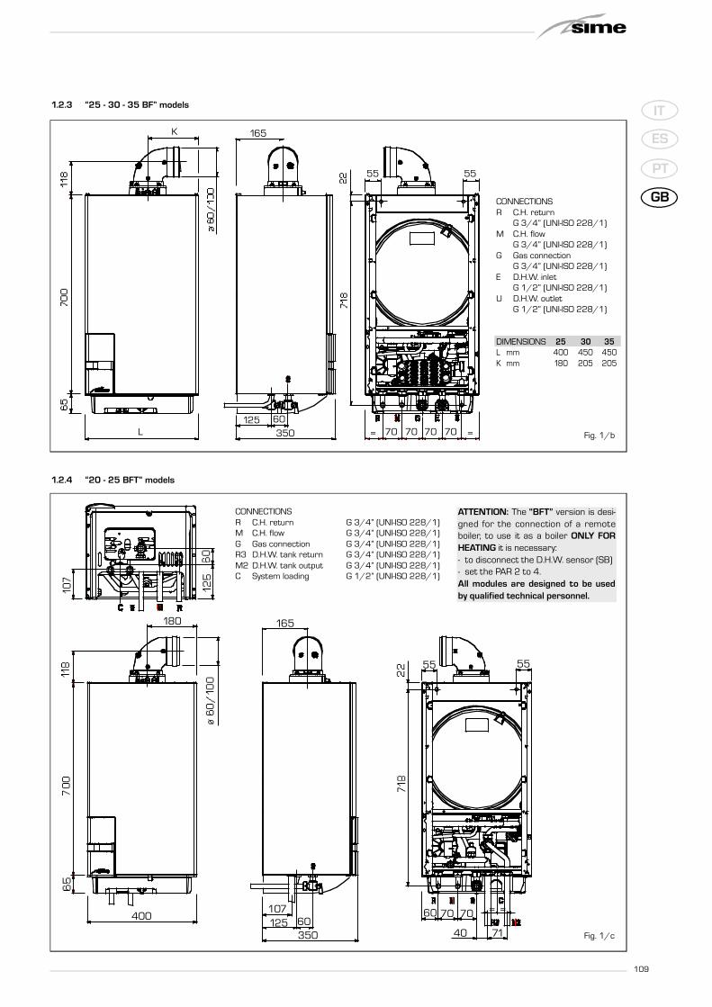
1.2.4 “20 - 25 BFT” models
CONNECTIONSR C.H. return G 3/4” (UNI-ISO 228/1)M C.H. flow G 3/4” (UNI-ISO 228/1)G Gas connection G 3/4” (UNI-ISO 228/1)R3 D.H.W. tank return G 3/4” (UNI-ISO 228/1)M2 D.H.W. tank output G 3/4” (UNI-ISO 228/1)C System loading G 1/2” (UNI-ISO 228/1)
70 70 70 70 ==350125 60
L
165K
55 55
Fig. 1/b
1.2.3 “25 - 30 - 35 BF” models
CONNECTIONSR C.H. return
G 3/4” (UNI-ISO 228/1)M C.H. flow
G 3/4” (UNI-ISO 228/1)G Gas connection
G 3/4” (UNI-ISO 228/1)E D.H.W. inlet
G 1/2” (UNI-ISO 228/1)U D.H.W. outlet
G 1/2” (UNI-ISO 228/1)
DIMENSIONS 25 30 35L mm 400 450 450K mm 180 205 205
ATTENTION: The “BFT” version is desi-gned for the connection of a re m oteb o i l e r, to use it as a boiler O N LY FO RHEATING it is necessary:- to disconnect the D.H.W. sensor (SB)- set the PAR 2 to 4.All modules are designed to be usedby qualified technical personnel.

110
IT
ES
PT
GB
* Gas consumption figures express the lowest calorific power of pure gas under standard conditions at 15°C – 1013 mbar; this figure may differ from the actualfigure, which is dependent on gas composition and environmental conditions.
Models 25 OF 30 OF 25 OFT 25 BF 30 BF 35 BF 20 BFT 25 BFT
Heat output
Nominal kW 23.0 27.0 23.0 23.7 28.0 32.4 19.8 23.7
Reduced kW 8.7 10.2 8.7 8.8 10.4 11.8 7.3 8.8
Heat input
Nominal kW 25.5 30.0 25.5 25.5 30.0 34.8 21.3 25.5
Reduced kW 10.2 12.0 10.2 10.2 12.0 13.5 8.5 10.2
Thermal yield 100% useful 90.0 90.0 90.0 93.0 93.3 93.1 93.0 93.0
Thermal yield useful at 30% of load 89.5 89.5 89.5 92.0 92.0 92.0 92.0 92.0
Termal efficiency (CEE 92/42 directive) ★★ ★★ ★★ ★★★ ★★★ ★★★ ★★★ ★★★
Losses after shutdown to 50°C (EN 483) W/h 200 235 200 89 96 96 89 89
Supply voltage V-Hz 230-50 230-50 230-50 230-50 230-50 230-50 230-50 230-50
Adsorbed power consumption W 75 90 80 100 115 135 105 105
E l e c t rical protection gra d e IP X4D X4D X4D X4D X4D X4D X4D X4D
C.H. setting range °C 30÷80 30÷80 30÷80 30÷80 30÷80 30÷80 30÷80 30÷80
Water content boiler l 7.1 8.0 7.1 7.1 8.0 8.0 7.1 7.1
Maximum water head bar 3 3 3 3 3 3 3 3
Maximum temperature °C 85 85 85 85 85 85 85 85
Header tank capacity l 7 8 7 7 8 8 7 7
Header tank pressure bar 1 1 1 1 1 1 1 1
D.H.W. setting range °C 30÷60 30÷60 - 30÷60 30÷60 30÷60 - -
D.H.W. flow rate (EN 625) l/min 10.7 12.7 - 11.1 13.2 15.3 - -
Continuous D.H.W. flow rate t 30°C l/min 10.9 12.9 - 11.3 13.4 15.5 - -
Minimum D.H.W. flow rate l/min 2.4 2.4 - 2.4 2.4 2.4 - -
D.H.W pressure min/max bar 0.2/7 0.2/7 - 0.2/7 0.2/7 0.2/7 - -
D.H.W. pressure min. nom. power bar 0.5 0.65 - 0.5 0.65 0.8 - -
Smokes temperature min/max °C 88/122 95/135 88/122 100/125 100/125 95/130 95/115 100/125
Smokes flow min/max g/s 18/20 18/20 18/20 16/16 18/18 21/21 15/15 16/16
CE certification No. 1312BS5038 1312BS5037
Category II2H3+ II2H3+
Type of appliance B11BS B22P-52P/C12-32-42-52-62-82
NOx emission class 3 (<150 mg/kWh) 3 (<150 mg/kWh)
Weight when empty kg 30 33 30 38 40 40 37 37
Main burner nozzle
Quantity nozzles n° 12 14 12 12 14 15 10 12
G20 nozzle diameter mm 1.30 1.30 1.30 1.30 1.30 1.30 1.30 1.30
G30/G31 nozzle diameter mm 0.77 0.77 0.77 0.77 0.77 0.80 0.76 0.77
Gas consumption *
Natural gas (G20) m3/h 2.70 3.17 2.70 2.70 3.17 3.68 2.25 2.70
LPG (G30/G31) kg/h 2.01 2.37 2.01 2.01 2.37 2.74 1.68 2.01
Burner gas pressure min/max
Natural gas (G20) mbar 1.8/11.0 1.9/11.1 1.8/11.0 2.0/11.8 2.1/12.0 2.2/13.7 1.9/11.0 2.0/11.8
Butane (G30) mbar 4.7/27.7 4.8/27.7 4.7/27.7 4.8/28.5 5.0/28.5 4.5/28.2 4.8/28.5 4.8/28.5
Propane (G31) mbar 4.7/35.7 4.8/35.7 4.7/35.7 4.8/36.5 5.0/36.5 4.5/36.2 4.8/36.5 4.8/36.5
Gas supply pressure
Natural gas (G20) mbar 20 20 20 20 20 20 20 20
Butane (G30) mbar 28–30 28–30 28–30 28–30 28–30 28–30 28–30 28–30
Propane (G31) mbar 37 37 37 37 37 37 37 37
1.3 T E CH N I CAL FEAT U R E S

111
IT
ES
PT
GB
1
2
3
4
25
15
8
247
11
171316
14
20 1922
23
12
28
29
3027
26
31
21
U
E
G M R C
1.4 FUNCTIONAL DIAGRAM
Fig. 2
“25-30 OF/25-30-35 BF” models
“20-25 BFT/25 OFT” models
23
9
4
3
2
1
724
8
12
11
1713
19
6
16
14
202221
18
5 15
U E G M R
KEY1 Fan (BF - BFT model)2 Primary exchanger3 Combustion chamber4 Gas valve5 D-H.W. exchanger with plates6 Pressure switch valve with loading7 C.H. sensor (SM)8 Safety thermostat9 D.H.W. sensor (SS)
11 Circulator with air release vent12 Expansion vessel13 3 BAR safety valve14 Boiler discharge15 Water flow meter16 Water pressure transducer17 Automatic bypass18 D.H.W. filter19 C.H. return cock (optional)20 C.H. flow cock (optional)21 D.H.W. cock (optional)22 Gas cock (optional)23 Connection plate (optional)24 Aqua Guard Filter System25 Motorised deviator valve26 Filler group (optional)27 D.H.W. storage tank BT 100 (optional)28 Boiler discharge (optional)29 D.H.W. sensor (SB)30 D.H.W. expansion vessel 4 litre (optional)31 D-H.W. safety valve 7 BAR (optional)
CONNECTIONSU D.H.W. outletE D.H.W. inletG Gas connectionM C.H. flowR C.H. returnC System loading

112
IT
ES
PT
GB
11
10
9
8
76
5
4
3
2
1
1.5 MAIN COMPONENTS
Fig. 3
KEY1 3 BAR safety valve2 Control panel3 Gas valve4 Burners5 Combustion chamber6 Smoke chamber
7 Smoke stat8 C.H. sensor (SM)9 Main exchanger
10 Ignition/detection electrode11 Coupling protection
“25 - 30 OF/25 OFT” models

113
IT
ES
PT
GB
11
13
9
87 6
5
4
3
2
1
12
10
14
Fig. 3/a
KEY1 3 BAR safety valve2 Control panel3 Burners4 Combustion chamber5 Fan6 Combustion analysis intakes7 Negative pressure intake
8 Positive pressure intake9 Smoke pressure switch
10 C.H. sensor (SM)11 Main exchanger12 Ignition/detection electrode13 Gas valve14 Coupling protection
“25 - 30 - 35 BF/20 - 25 BFT” models

114
IT
ES
PT
GB
The boiler must be installed in a fixed loca-tion and only by specialized and qu a l i fi e dfi rms in compliance with all inst ru c t i o n scontained in this manual. Furthermore, theinstallation must be in accordance with cur-rent standards and regulations.
2.1 INSTALLATION
- In the rooms where “type B” boilers arei n stalled, the air re qu i red for corre c tc o m b u stion of the gas consumed by th eappliance must be able to flow in. It is the-re fo re necessary to make openings th a tc a n n ot be blocked in the outer wa l l s ,w h i ch must be at least 6 cm2 for eve rykW of thermal capacity installed and with,in any case, a minimum of 100 cm2.
- “Type C” appliances, with combust i o nchamber and air supply sealed off fro mthe environment, can be installed in anyroom in the house.
- “Type B and C” boilers are suitable fo rfunctioning in a partially protected place,as according to EN 297, with maximumenvironmental temperature of 60°C andminimum of -5°C. We recommend instal-lation of these boilers under the protru-ding slope of a roof, on a balcony, or in ap rote c ted niche, always providing th eya re not dire c t ly exposed to adve rs eweather (rain, hail, snow). The boilers areprovided already equipped with anti-free-ze functions.
2.1.1 Anti-freeze function
The boilers are equipped with anti-fre e z efunction which activates the pumps and theburner when the temperature of the waterc o n tained inside the appliance drops tobelow 6°C. The anti-freeze function is ensu-red, however, only if:- the boiler is correctly connected to the
gas and electricity supply circuits;- the boiler is constantly fed;- the boiler ignition is not blocked;- the essential components of the
boiler are all in working orderIn these conditions the boiler is prote c te da ga i n st fro st down to an env i ro n m e n ta ltemperature of -5°C.
ATTENTION: In the case of installation in aplace where the temperature drops below0°C, the connection pipes must be pro-tected.
2.2 COMPLEMENTARYACCESSORIES
To fa c i l i ta te connecting the boiler to th es ystem, the fo l l owing accessories can besupplied on request, complete with instruc-tions for assembly:- Installation plate code 8075416- C u rvet te and gas ta p s / s a n i ta ry wa te r
output set code 8075418
- Taps kit code 8091806- Po l y p h o s p h a tes doser k it code
81071700- Kit of couplings for replacing wa l l - h u n g
boilers of other makes code 8093900- Solar kit for the insta n taneous code
8105101- H y d raul ic connect ion ki t boi ler
BFT/BT100 tank unit code 8091111.
2.3 CONNECTING UP SYSTEM
To protect the heat system from damagingc o rrosion, incru station or deposits, befo rei n stallation it is ex t re m e ly imp o rtant toclean the system using suitable pro d u c t ss u ch as, for exa mple, Sentinel X300 orX400. Comp l ete inst ructions are prov i d e dwith the products but, for further informa-tion, you may dire c t ly contact SENTINELPERFORMANCE SOLUTIONS LTD.For long-te rm protection agains corro s i o nand deposits, the use of inhibitors such asSentinel X100 is recommended after clea-ning the system. It is imp o rtant to ch e ckthe concentration of the inhibitor afte reach system modification and during main-tenance fo l l owing the manufa c t u re r’sinstructions (specific tests are available atyour dealer). The safety valve drain must bec o n n e c ted to a collection funnel to collectany disch a rge during inte rventions. If th eheating system is on a higher floor than theboiler, install the on/off taps supplied in kito p t ional on the heat ing sys te mdelivery/return pipes.
WA R N I NG: Fa i l u re to clean th eheat system or add an adequateinhibitor invalidates the device’s
warranty.Gas connections must be made in accor-
dance with current sta n d a rds and re g u l a-tions. When dimensioning gas pipes fro mthe meter to the module, both capacityvolume (consumption) in m3/h and ga sdensity must be taken into account. The sections of the piping making up thesystem must be such as to guarantee asupply of gas sufficient to cover the maxi-mum demand, limiting pre s s u re lossbetween the gas meter and any apparatusbeing used to not greater than:– 1.0 mbar for family II gases (natural gas);– 2.0 mbar for fa m i ly III gases (butane or
propane).
An adhesive data plate is sticked inside thefront panel; it contains all the technical dataidentifying the boiler and the type of gas forwhich the boiler is arranged.
2.3.1 Filter on the gas pipe
The gas valve is supplied ex factory with aninlet filter, which, however, is not adequateto entrap all the impurities in the gas or ingas main pipes.To prevent malfunctioning of the valve, or incertain cases even to cut out the safetydevice with which the valve is equipped,install an adequate filter on the gas pipe.
2.5 SYSTEM FILLING
Filling of the boiler and the system is doneby the charge cock (2 fig. 4). The chargepressure, with the system cold, must bebetween 1 and 1.5 bar. During system fil-ling you are recommended to keep the mainswitch turned OFF. Filling must be doneslowly so as to allow any air bubbles to be
2 INSTALLATION
Fig. 4
81
10 11 3 2 9 4
675
12
8
12 13 11
9 414
“25-30 OF/25-30-35 BF” models
“20-25 BFT/25 OFT” models
KEY1 Sanitary water header2 Fill tap3 D.H.W. filter4 By-pass5 Water rate adjuster6 D.H.W. exchanger7 Microswitches8 Water flow switch9 Boiler discharge
10 D.H.W. sensor11 Water pressure transducer12 Safety thermostat13 Deviator valve14 System loading connection

115
IT
ES
PT
GB
bled off through the air valves. Should thepressure have risen well above the limitexpected, discharge the over pressure byopening the pressure-relief valve.
N.B. The OFT/BFT versions are loaded bymeans of the special coupling indicated infigs. 1/a - 1/c
2.5.1 Emptying the system
Use the drain tap to empty the system (9fig. 4). Turn off the boiler before doing this.
2.6 FLUES/CHIMNEYS
A chimney or flue for the evacuation of thec o m b u stion products into the atmospheremust correspond to the requisites prescri-bed by the laws in force.In part i c u l a r, the specific pre s c ri ptions oflaw relative to boilers with natural draughtin collective pipes (type B) and those for boi-l e rs with fo rced draught (type C) must berespected.
2.6.1 Ducting of existing chimneys
To recover or duct existing chimneys, ductsd e c l a red suitable for the purpose by th emanufacturer must be used, and the instal-lation and use modalities indicated by th esaid manufa c t u rer must also be fo l l owe das well as the pre s c ri ptions of Sta n d a rdUNI 10845.
2.7 INSTALLATION OF COAXIALDUCT (versions "BF - BFT")
2.7.1 Accessories 60/100
The 60/100 coaxial duct is supplied onrequest in kit code 8084811.The diagrams of f ig. 5 i llust ra te someexa mples of dif fe rent types of disch a rgemodal it ies al lowed and the maximum
lengths that can be reached.
2.7.2 Diaphragm for 60/100coaxial duct
The boiler is supplied with a diaphragm of
84 (version 20 BFT), 86 (versions 25-35BF/25 BFT) and 87.5 (version 30 BF). Thediaphragms 87.5 (code 6028824) and 86(code 6028623) can be requested separa-tely. Use the diaphragms according to theindications of fig. 5/a.
C12
C32
C42
3
1
2
7
64
3
2
8
x
y
max 5,0 m per vers. “20”max 3,5 m per vers. "25"max 3,0 m per vers. "30-35"
x + y = max 5,0 m per vers. "20"x + y = max 3,5 m per vers. "25"x + y = max 3,0 m per vers. "30-35"
KEY1 Coaxial flue kit L. 810 code 80848112 a Extension L. 1000 code 80961032 b Extension L. 500 code 80961023 Vertical extension L. 200 code 80869084 Additional 90° curve code 80958016 Articulated tile code 80913007 Roof outlet terminal L. 1284 code 80912008 Vertical condensation collector L. 200 code 8092803 Fig. 5
IMPORTANT:– E a ch additional 90° curve
installed reduces the availablelength by 1.0 metres.
– E a ch additional 45° curveinstalled reduces the availablelength by 0.50 metres.
- The insertion of the condensa-tion collector (8) is obligatoryfor vertical stretches of morethan 1.3 metres.
For discharge types C12-C42, use the diaphragms supplied with the boiler:- ø 84.0 for version “20” only when the length of the coaxial duct is less than 2 metres,- ø 86.0 for version “25-35” only when the length of the coaxial duct is less than 1 metre,- ø 87.5 for version “30” only when the length of the coaxial duct is less than 2 metres.
For discharge types C32, use the following diaphragms according to the length of the duct and withoutadditional curves:
Installations with vetrical Installations with vertical condensationextension L. 200 code 8086908 * collector code 8092803 *
“20 BFT” models “20 BFT” modelsDiaphragm Diaphragm Without Diaphragm Diaphragm Without
ø 84 ø 86 diaphragm ø 84 ø 86 diaphragm(code 6028622) (code 6028623) (code 6028622) (code 6028623)
L max = 4 m L max = 5 m ---- L max = 3 m L max = 5 m ---“25 BF - 25 BFT - 30 BF - 35 BF” models “25 BF - 25 BFT - 30 BF - 35 BF” models
Diaphragm Diaphragm Without Diaphragm Diaphragm Withoutø 86 ø 87,5 diaphragm ø 86 ø 87,5 diaphragm
(code 6028623) (code 6028624) (code 6028623) (code 6028624)L max = 2.5 m L max = 4 m L max = 5 m --- L max = 2.5 m L max = 4 m
* Minimum length of duct L = 1.3 m.Fig. 5/a

116
IT
ES
PT
GB
2.7.3 Accessories 80/125
The 80 coaxial duct is supplied on requestin a kit code 8084830 comp l ete withassembly instructions.Wi th the curve supplied in the kit, the maxi-mum hori z o n tal length of the duct must beno more than 6 met re s .
The diagrams in fig. 6 show some examplesof the diffe rent types of 80/125 coaxialdischarge modalities.
2.8 INSTALLATION OF SEPARATEDUCTS (versions “BF - BFT”)
When installing, the provisions of the lawsin force must be adhered to, as well as cer-tain practical suggestions:
– Wi th aspiration dire c t ly from outside,when the duct is longer than 1 metre, itis advisable to insulate the said duct ino rder to avoid the fo rmation of dew onthe outside of the pipe when the weather
is particularly cold.
– Wi th ducts with disch a rge positionedoutside the building, or in cold env i ro n-ments, insulation is necessary to avo i dd i fficulty in sta rting the burn e r. In th e s ecases, a condensation system on th epipes must be provided for.
– If the pipe passes th rough infl a m m a b l ewalls, insulate the st ret ch of the fumesd i s ch a rge pipe that passes th rough th e
C12
C32
C42
27
64
1
2
8
x
y
x + y = min. 3,5 m/max 6 m "25"x + y = min. 3,0 m/max 6 m "30-35"
5
53 8
2
1
1
min. 3,5 m - max 6 m "25"min. 3,0 m - max 6 m "30-35"
2
Fig. 6
KEY1 Coaxial duct kit code 80848302 Extension L. 1000 code 80961303 Vertical extension L. 200 with coupling code 80869084a Additional 90° curve code 80958204b Additional 45° curve code 80959205 Adapter for 80/125 code 80959206 Tile for joint code 80931207 Terminal for roof exit L. 1284 code 80912008 Vertical condensation collector L. 200 code 8092803
IMPORTANT:– Each additional 90° curve installed reduces the available length by 1.0 metres.– Each additional 45° curve installed reduces the available length by 0.80 metres.– The insertion of the condensation collector (8) is obligatory in C32 discharge type.– The insertion of the condensation collector (8) is obliga to ry in C42 disch a rge type
when the stretch "y” is longer than 1.3 metres.

117
IT
ES
PT
GB
wall with rounded glass wool 30 mmthick and with a density of 50 kg/m2.
The maximum total length , w h i ch is th esum of lengths of the aspiration anddischarge pipes, is determined by the lossof charge of the single accessories inser-ted and must not result as more than 7.0mm H2O in version “20” - 7.6 mm H2O inversion “25” - 9 mm H2O in version “30” -12 mm H2O in version “35”.
For the loss of ch a rge of the accessori e s ,refer to Table 1 and to the example given infig. 7.
2.8.1 Separate ducts kit
The separate ducts kit code 8089904 (fig.8) is supplied with the aspiration diaph-ragm which must be used, according to themaximum loss of ch a rge allowed in boththe ducts, as indicated in fig. 8/a.To use the air inta ke vent in this type ofdischarge, the following operations must becarried out (fig. 9):– Re m ove the base of the air inta ke ve n t
by cutting it with a tool (a);
Example of allowable installation “25 BF” calculation in that the sum of the head losses of thesingle fittings is less than 7.6 mm H2O:
Intake Outlet7 meter horizontal pipe ø 80 x 0.20 1.40 –7 meter horizontal pipe ø 80 x 0.30 – 2.10No. 2 90° elbows ø 80 x 0.35 0.70 –No. 2 90° elbows ø 80 x 0.40 – 0.80No. 1 wall terminal ø 80 0.15 0.50
Total head loss 2.25 + 3.40 = 5.65 mmH2O
With this total head loss, remove the segments from No. 1 to No. 7 from diaphragm in the intakepipe.
1
2
3
46
Fig. 8
Fig. 8/a
Fig. 7
KEY1 ø 125/95 sponge seal2 Fixing screw3 Flue outlet flange4 Inlet air diaphragm6 Manifold with intakes
20 25 30 35K mm 180 180 205 205
TABLE 1
Accessories ø 80 Load loss (mmH2O)
20 25 30 35
Intake Outlet Intake Outlet Intake Outlet Intake Outlet
90° curve MF 0.30 0.35 0.35 0.40 0.45 0.50 0.65 0.70
45° curve MF 0.25 0.30 0.30 0.35 0.40 0.45 0.60 0.65
E x tension L. 1000 (hori z o n ta l ) 0.15 0.25 0.20 0.30 0.25 0.35 0.30 0.40
E x tension L. 1000 (ve rt i c a l ) 0.15 0.05 0.20 0.10 0.25 0.15 0.30 0.20
Wall terminal 0.10 0.40 0.15 0.50 0.20 0.80 0.20 1.20
T-shaped condensation collector --- 0.70 --- 0.80 --- 1.00 --- 1.40
Roof exit terminal* 1.30 0.05 1.60 0.10 2.00 0.20 2.50 0.30
* The loss of the roof exit terminal in aspiration concludes the collector code 8091400
No. s e g m e n t s Total load loss mm H2Oto re m ove 20 25 30 35
none 0 ÷ 2.0 0 ÷ 0.8 - -No. 1 2.0 ÷ 3.0 0.8 ÷ 1.6 - -
No. 1 e 2 3.0 ÷ 4.0 1.6 ÷ 2.4 0 ÷ 1.0 0 ÷ 1.0from No. 1 to 3 4.0 ÷ 5.0 2.4 ÷ 3.1 1.0 ÷ 2.0 1.0 ÷ 2.0from No. 1 to 4 5.0 ÷ 6.0 3.1 ÷ 3.8 2.0 ÷ 3.0 2.0 ÷ 3.0from No. 1 to 5 6.0 ÷ 7.0 3.8 ÷ 4.5 3.0 ÷ 4.0 3.0 ÷ 4.0from No. 1 to 6 --- 4.5 ÷ 5.2 4.0 ÷ 4.8 4.0 ÷ 5.0from No. 1 to 7 --- 5.2 ÷ 5.8 4.8 ÷ 5.6 5.0 ÷ 6.0from No. 1 to 8 --- 5.8 ÷ 6.4 5.6 ÷ 6.4 6.0 ÷ 7.0from No. 1 to 9 --- 6.4 ÷ 7.0 6.4 ÷ 7.2 7.0 ÷ 8.0from No. 1 to 10 --- - 7.2 ÷ 8.0 8.0 ÷ 10.0
without diaphragm --- 7.0 ÷ 7.6 8.0 ÷ 9.0 10.0 ÷ 12.0

118
IT
ES
PT
GB
– Turn the air intake vent upside down andreplace the gasket (5) with that suppliedin the kit code 8089904;
– Insert the aspiration diaphragm suppliedin the kit code 8089904, pushing ithome;
– Only for versions "20 BFT” fit onto thediaphragm the plastic reducer suppliedtogether with the boiler.
Now the extension or the curve can be fit-ted into the special seat in order to comple-te the aspiration pipe (no washer or sealantis necessary).
2.8.2 Outlet systems
The diagrams in fig. 9/a illust ra te a num-ber of examples of different types of sepa-
max 0,5 m
C12B52
1
4
9
C52B52
C32
C42
3
2
11
10
C82B22
6
5
6
12
3
11
10
3
7
1
8
3
1
3
2
3
3 2
1
3
23 63
1
8 3
KEY1 Separate flue kit code 8089904
2a 90° elbow MF (n° 6) code 80774102b 90° elbow MF with intake code 80774072c Isolated 90° elbows MF code 80774083a Extension L. 1000 (n° 6) code 80773093b Insulated extension L. 1000 code 80773063c Extension L. 500 (n° 6) code 80773083d Extension L. 135 code 8077304
4 Outlet terminal code 80895015 Int.-est. ring kit code 80915006 Intake terminal code 80895007 45° elbow MF (n° 6) code 80774118 Condensation outlet L. 135 code 80928009 Doubler fitting code 8091400
10 Tile with articulated joint code 809130011 Roof outlet terminal L. 1390 code 809120112 Tee condensation outlet code 8093300
a
b
5
Fig. 9/aIMPORTANT: In type C52 the outlet and inlet flues must not come out on opposite walls.
ATTENTION: The three seats fore-seen on the diaphragm allow for fit-ting the air intake vent in only oneposition (the enumeration of th esectors faces inwards).
Fig. 9
CONFIGURATION C62: discharge and aspiration is by means of pipes available on sale and certified separately (the pressure loss in theducts must be calculated according to the Standard UNI EN 13394)
In vers. “20 BFT” fit the plasticreducer supplied with the boiler inthe position indicated.
119
IT
ES
PT
GB
rate outlets.
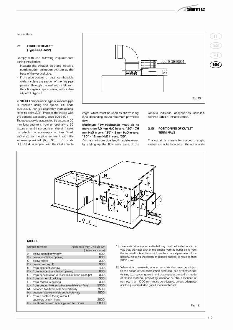
2.9 FORCED EXHAUST (Type B22P-52P)
C o mp ly with the fo l l owing re qu i re m e n t sduring installation:– I n s u l a te the ex h a u st pipe and install a
condensation collection system at th ebase of the vertical pipe.
– If the pipe passes th rough combust i b l ewalls, insulate the section of the flue pipepassing through the wall with a 30 mmthick fibreglass pipe covering with a den-sity of 50 kg/m3.
In “BF-BFT” models this type of exhaust pipeis installed using the special kit, code8089904. For kit assembly instructions,refer to point 2.9.1. Protect the intake withthe optional accessory, code 8089501.The accessory is assembled by cutting a 50mm long segment from an ordinary ø 80extension and inserting it on the air intake,on which the accessory is then fi t te d ,anchored to the pipe segment with thes c rews provided (fig. 10). Kit code8089904 is supplied with the intake diaph-
ragm, which must be used as shown in fig.8/a, depending on the maximum permittedflow.Maximum fl ow re s i stance must be nomore than 7,0 mm H2O in vers. “20” - 7,6mm H2O in vers. “25” - 9 mm H2O in vers.“30” - 12 mm H2O in vers. “35”.As the maximum pipe length is determinedby adding up the flow resistance of the
va rious individual accessories insta l l e d ,refer to Table 1 for calculation.
2.10 POSITIONING OF OUTLETTERMINALS
The outlet te rminals for fo rced dra u g h tsystems may be located on the outer walls
1) Terminals below a practicable balcony must be located in such away that the total path of the smoke from its outlet point fromthe terminal to its outlet point from the external perimeter of thebalcony, including the height of possible railings, is not less than2000 mm.
2) When siting te rminals, where mate rials that may be subjectto the action of the combustion products are present in thevicinity, e.g., eaves, gutters and downspouts painted or madeof plastic mate rial, projecting timberwo rk, etc., distances ofn ot less than 1500 mm must be adopted, unless adequ a teshielding is provided to guard these materials.
Fig. 11
cod. 8089501
Fig. 10
TABLE 2
Siting of terminal Appliances from 7 to 35 kW(distances in mm)
A - below openable window 600B - below ventilation opening 600C - below eaves 300D - below balcony (1) 300E - from adjacent window 400F - from adjacent ventilation opening 600G - from horizontal or vertical soil or drain pipes (2) 300H - from corner of building 300I - from recess in building 300L - from ground level or other treadable surface 2500M - between two terminals set vertically 1500N - between two terminals set horizontally 1000O - from a surface facing without
openings or terminals 2000P - as above but with openings and terminals 3000

120
IT
ES
PT
GB
of the building Table 2 shows approximate,non-binding minimum distances to be metfor a building of the type shown in fig. 11.
2.11 ELECTRICAL WIRING
If you must replace the electric powe rcable supplied with the boiler, order it exclu-sively from Sime. The power supply must besingle-phase 230V - 50 Hz through a mainswitch protected by a fuse with a distanceof at least 3 mm between contacts.
NOTE: The boiler must be connected withan efficient grounding system. SIME shalln ot be held liable for injury or damageresulting from fa i l u re to ground the boi-ler.
ATTENTION: Before every inter-vention on the boiler, cut off theelectricity supply by means of
the main switch of the system, since evenif the boiler is "OFF", the electrical panelremains connected to the electricity.
2.11.1 Chronothermostatconnection
Connect the ch ro n oth e rm o stat as indica-ted in the boiler electrical diagram (seep a ra graph 2.12) after having re m oved th eexisting bridge.The chronothermostat to be used must beof a class confo rming to the sta n d a rd EN607301 (clean electrical contact).
2.11.2 Climatic regulator CR 53 connection (optional)
The boiler is designed for connectio to a cli-matic regulator, supplied on request (code8 0 9 2 2 27), for the management of a hea-ting circuit.The electronic card will continue to manageinformation visualisation, the setting of thesanitary set and the heating of the secondc i rcuit, and the boi ler para m ete rs bymeans of the keys on the control panel.For installation and use of the climatic regu-lator, follow the instructions included in thepackaging.NOTE: Reset parameter 10 to 2 (PAR 10= 2).
2.11.3 Remote control CR 73connection (optional)
The boiler is designed for connection to are m ote control unit, supplied on re qu e st(code 8092226).The re m ote control unit CR 73 allows fo rc o mp l ete re m ote control of the boiler,exc e pt release of the boiler. The boilerdisplay will show the following message:
For installation and use of the remote con-trol, follow the instructions in the package.NOTE: Ensure PAR 10 set to 1 (PAR 10 =1).
2.11.4 External sensor connection
The boiler is designed for connection to anex te rnal te mp e ra t u re sensor, supplied onre qu e st (code 8094101), which can auto-matically regulate the temperature value ofthe boiler output according to the externalte mp e ra t u re. For installation, fo l l ow th einstruction in the package. For installation,fo l l ow the inst ruction in the packa ge . It ispossible to make corrections to the va l u e sread by the drill acting on the PAR 11.
2.11.5 D.H.W. sensor connection in vers."20-25 BFT/25 OFT"
The “20-25 BFT/25 OFT” version is provi-ded with D.H.W. sensor (SB) linked to th econnector CN5. When the boiler is coupledto D.H.W. storage tank, introduce the sen-sor into the special sleeve in the D.H.W.storage tank.ATTENTION: The “BFT/OFT” ve rsion isdesigned for connection to D.H.W. stora-ge tank, for use ONLY FOR HEATING it isnecessary:- to disconnect the D.H.W. sensor (SB);- set PAR 2 and 4.All modules are designed to be used byqualified technical personnel.
2.11.6 Use with differentelectronic systems
Some exa mples are given below of boilersystems combined with different electronics ystems. Where necessary, the para m e-te rs to be set in the boiler are given. Theelectrical connections to the boiler refer tothe wo rding on the diagrams (figs. 13 -13/a). The zone va lve control sta rts atevery demand for heating of the zone 1 (itis from part of the TA1 or the CR).D e s c ri ption of the let te rs indicating th ec o mponents shown on the system dia-grams:M System outputR System returnCR Remote control CR 73SE External temperature sensorTA 1-2-3-4 Zone room thermostatCT 1-2 Zone chronothermostatVZ 1-2 Zone valveRL 1-2-3-4 Zone relaySl Hydraulic separatorP 1-2-3-4 Zone pumpSB D.H.W. sensorPB D.H.W. pumpIP Floor systemEXP Expansion card (code 8092233)VM Three-way mixer valve
RM
SE
TA
CR
TA1
CRSE
1 BASIC SYSTEMSYSTEM WITH A DIRECT ZONE AND ROOM THERMOSTAT,OR WITH A CLIMATIC REGULATOR CR 53 (Code 8092227 )OR WITH REMOTE CO N T ROL CR 73 (Code 8092226) ANDEXTERNAL SENSOR (Code 8094101)
PARAMETERS SETTINGS
If using CR 53 set parameter10 to 2 (PAR 10 = 2)

121
IT
ES
PT
GB
TA1SE
RM
SETA
VZ
TA1
VZ1
TA2
VZ2
RMSE
TA1 TA2
TA1
SE
TA
P2
RL
SI
RL1 RL2
P1P
TA2SE
RMSE
TA
VZ
TA1
VZ1
TA2
VZ2
CR
CR
2 BASIC SYSTEMMULTI-ZONE SYSTEM WITH VALVE, ROOM THERMOSTAT AND EXTERNAL SENSOR (Code 8094101)
3 BASIC SYSTEMMULTI-ZONE SYSTEM WITH PUMP, ROOM THERMOSTAT AND EXTERNAL SENSOR (Code 8094101)
4 BASIC SYSTEMMULTI-ZONE SYSTEM WITH VALVE, ROOM THERMOSTAT, REMOTE CONTROL CR 73 (Code 8092226) ANDEXTERNAL SENSOR (Code 8094101)
PARAMETERS SETTINGS
To use the remote control(CR) as remote control panelfor the boiler rather than asroom reference, set:PAR 7 = 0

122
IT
ES
PT
GB
TA2
SE
RMSE
VZ VZ1
TA2
VZ2
CR
CR
VZ1
TA1
RMSE
CT2
TA1
SE
CT1
TA2
VZ1 VZ2
ZONAGIORNO(70°C)
ZONANOTTE(50°C)
DURING NIGHT TIME THE BOILERUSES A LOWER OUTPUT TEMPERA-TURE IF DIFFERENT TIMES HAV EBEEN SET FOR DAY AND NIGHTAREAS:- with external sensor, set the cli-
matic curve of the day zone 1 withPAR 25 and the night zone at PAR26.
- w i thout ex te rnal sensor, ga i naccess to setting the day zone 1 by
pressing the key and change
the value with the keys and
. Gain access to setting the
night zone by pressing the keytwice and changing the value with
the keys and .
SI
RMSE
TA1 TA2
TA2SE
TA
P2
RL RL1 RL2
P1PCR
CR
5 BASIC SYSTEMMULTI-ZONE SYSTEM WITH VALVE, ROOM THERMOSTAT, REMOTE CONTROL CR 73 (Code 8092226)AND EXTERNAL SENSOR (Code 8094101)
6 BASIC SYSTEMMULTI-ZONE SYSTEM WITH PUMP, ROOM THERMOSTAT, REMOTE CONTROL CR 73 (Code 8092226)AND EXTERNAL SENSOR (Code 8094101)
7 SYSTEM WITH DOUBLE TEMPERATURE OUTPUTMULTI-ZONE SYSTEM WITH VALVE, CHRONOTHERMOSTAT AND EXTERNAL SENSOR (Code 8094101)
DAYZONE(70°C)
NIGHTZONE(50°C)
PARAMETER SETTING
To use the remote control(CR) as room reference for azone, set: PAR 7 = 1
Set the opening time of thezone valve VZ:PAR 33 = “OPENING TIME”
PARAMETER SETTING
To use the remote control(CR) as room reference for azone, set:PAR 7 = 1

123
IT
ES
PT
GB
RM
SE
CR
CRSE
SB
M2 R2
SB
BOLLITORE
PARAMETER SETTING
MURELLE BFT with D.H.W sen-sor to be set:PAR 3 = 2
MURELLE BFT only for heatingto be set:PAR 2 = 4
Alternatively it is possible touse a TA connected to th eentrance TA1.
RM
SE
TA2
TA1
SE
TA1
SI
RL2
P2P1
PB
RL1
BOLLITORE
PB
SB
SB
RMSE
CT2
TA1
SE
CT1
SI
RL2
P2P1
TA2
RL1
ZONAGIORNO(70°C)
ZONANOTTE(50°C)
8 SYSTEM WITH DOUBLE TEMPERATURE OUTPUTMULTI-ZONE SYSTEM WITH PUMP, CHRONOTHERMOSTAT AND EXTERNAL SENSOR (Code 8094101)
9 SYSTEM WITH REMOTE BOILING UNIT
10 SYSTEM WITH REMOTE BOILING UNIT AFTER THE HYDRAULIC SEPARATOR
DAYZONE(70°C)
NIGHTZONE(50°C)
D.H.W. TANK
D.H.W. TANK
124
IT
ES
PT
GB
RMSE
TA2
TA1
SE
TA1
SI
RL2
P2
P1
TA2
CR
CR
EXP
VM
EXP
IP
RMSE
TA3
TA1
SE
SI
RL3
P3
P2
TA2
IP
EXP
VM
EXP IP
P4
TA4
RL4
TA1 TA2
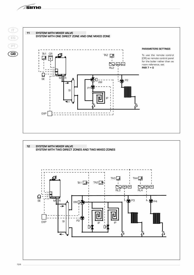
11 SYSTEM WITH MIXER VALVESYSTEM WITH ONE DIRECT ZONE AND ONE MIXED ZONE
12 SYSTEM WITH MIXER VALVESYSTEM WITH TWO DIRECT ZONES AND TWO MIXED ZONES
PARAMETERS SETTINGS
To use the remote control(CR) as remote control panelfor the boiler rather than asroom reference, set:PAR 7 = 0

125
IT
ES
PT
GB
2.12 BOILER ELECTRICAL DIAGRAM
“25-30 OF” models
Fig. 13
KEYF1-2 Fuse (4 AT)TRA Ignition transformerPl System pumpEAR Ignition/detection electrodeEV1-2 Gas valve coilTS Safety thermostatTF Fumes thermostatVP Pressure switch valveM ModulatorSM Heating sensorFL Water flow meterSS D.H.W sensorTPA Pressure transducerTA 1 Zone 1 environment thermostatTA 2 Zone 2 environment thermostatST Solar heat sensorCR Remote control CR 73 (optional)SE External sensor (optional)OP Programming clock (optional)EXP Expansion cardVZ Zone valveAUX Auxiliary connection
NOTE: Connect TA1 to the clamps 7-8after having removed the bridge.
CONNECTOR SPARE PART CODES:CN2 cod. 6299992CN3 cod. 6299998CN4 cod. 6316203CN5 cod. 6316200CN6 cod. 6316202CN7 cod. 6316204CN10 cod. 6316227CN11 cod. 6316226CN12 cod. 6299991CN13 cod. 6299997
“25 OFT” modelsKEYF1-2 Fuse (4 AT)TRA Ignition transformerPl System pumpEAR Ignition/detection electrodeEV1-2 Gas valve coilTS Safety thermostatTF Fumes thermostatM ModulatorSM Heating sensorFL Water flow meterVD Deviator valveSS D.H.W. sensorTPA Pressure transducerTA 1 Zone 1 environment thermostatTA 2 Zone 2 environment thermostatSB D.H.W. tank sensorCR Remote control CR 73 (optional)SE External sensor (optional)OP Programming clock (optional)EXP Expansion cardPR/AR Recirculation pump control or
remote alarmVZ Zone valveAUX Auxiliary connection
NOTE: Connect TA1 to the clamps 7-8after having removed the bridge.
CONNECTOR SPARE PART CODES:CN2 cod. 6299999CN3 cod. 6299998CN4 cod. 6316203CN5 cod. 6316200CN6 cod. 6316202CN7 cod. 6316204CN9 cod. 6316201CN10 cod. 6316227CN11 cod. 6316226CN12 cod. 6299991CN13 cod. 6299997

126
IT
ES
PT
GB
KEYF1-2 Fuse (4 AT)TRA Ignition transformerPI System pumpV FanEAR Ignition/detection electrodeEV1-2 Gas valve coilTS Safety thermostatPF Fumes thermostatVP Pressure switch valveM ModulatorSM Heating sensorFL Water flow meterSS D.H.W. sensorVD Deviator valveTPA Pressure transducerTA 1 Zone 1 environment thermostatTA 2 Zone 2 environment thermostatST Solar heat sensorCR Remote control CR 73 (optional)SE External sensor (optional)OP Programming clock (optional)EXP Expansion cardVZ Zone valveAUX Auxiliary connection
NOTE: Connect TA1 to the clamps 7-8after having removed the bridge.
CONNECTOR SPARE PART CODES:CN2 cod. 6299992CN3 cod. 6299993CN4 cod. 6316203CN5 cod. 6316200CN6 cod. 6316202CN7 cod. 6316204CN10 cod. 6316227CN11 cod. 6316226CN12 cod. 6299991CN13 cod. 6299990
Fig. 13/a
“25-30-35 BF” models
“20-25 BFT” models KEYF1-2 Fuse (4 AT)TRA Ignition transformerPl System pumpV FanEAR Ignition/detection electrodeEV1-2 Gas valve coilTS Safety thermostatPF Fumes thermostatVP Pressure switch valveM ModulatorSM Heating sensorFL Water flow meterVD Deviator valveTPA Pressure transducerTA 1 Zone 1 environment thermostatTA 2 Zone 2 environment thermostatSB D.H.W. tank sensorCR Remote control CR 73 (optional)SE External sensor (optional)OP Programming clock (optional)EXP Expansion cardPR/AR Recirculation pump control
or remote alarmVZ Zone valveAUX Auxiliary connection
NOTE: Connect TA1 to the clamps 7-8after having removed the bridge.
CONNECTOR SPARE PART CODES:CN2 cod. 6299999CN3 cod. 6299993CN4 cod. 6316203CN5 cod. 6316200CN6 cod. 6316202CN7 cod. 6316204CN9 cod. 6316201CN10 cod. 6316227CN11 cod. 6316226CN12 cod. 6299991CN13 cod. 6299990

127
IT
ES
PT
GB
3.1 CONTROL PANEL
3 CHARACTERISTICS
5
3
1
2
4
1 - DESCRIPTION OF DISPLAY ICONS
SUMMER MODE ICON
WINTER MODE ICON
D.H.W. MODE ICON
HEATING MODE ICON1 = First circuit heating system2 = Second circuit heating system
GRADED POWER SCALEThe segments of the bar light up in pro p o rtion to boiler p owe routput .
2 - DESCRIPTION OF CONTROLS
ON/OFF KEYSON = Electricity supply to boiler is onOFF = Electricity supply to boiler is on but nor ready for
functioning. Howeve r, the protection functionsare active.
SUMMER MODE KEYWhen this key is pressed, the boiler functions onlywhen D.H.W. is requested.
WINTER MODE KEYWhen this key is pressed, the boiler provides heatingand D.H.W.
D.H.W. TEMP KEYWhen this key is pressed, the te mp e ra t u re of th eD.H.W. is shown on the display.
HEATING TEMP KEYThe first time the key is pressed, the temperature ofheating circuit 1 is shown.The second time the key is pressed, the temperatureof heating circuit 2 is shown.
RE-SET KEYThis allows for restoring functioning after a functioninganomaly.
INCREASE AND DECREASE KEYBy pressing this key the set value increases or decrea-ses.
BURNER FUNCTIONING AND BLOCK ICON
DESCRIPTION OF DISPLAY ICONS
CHIMNEY SWEEP ICON
SECONDARY DIGITSThe boiler visualises the value of the pressure of thesystem (correct value is between 1 and 1.5 bar)
3 - KEYS RESERVED FOR THE INSTALLER(access to INST and OEM parameters)
4 - LUMINOUS BARBlue = FunctioningRed = Functioning anomaly
5 - PROGRAMMING CLOCK (optional)M e chanical clock (code 8092228) or digital clock (code8092229) to program heating and water supply.
MAIN DIGITSThe boiler visualises the values set, the sta teof anomaly and the external temperature
Fig. 14
PC CONNECTIONTo be used only with the SIME programming kit and onlyby authorised personnel. Do not connect other electro-nic devices (cameras, telephones, mp3 playe rs, et c . )Use a tool to remove the cap and reinsert after use.ATTENTION: Communication portsensitive to electrostatic charges.Before use, it is advisable to touch an earthed metallicsurface to discharge static electricity.
INFORMATION KEYThis key can be pressed several times to view the para-meters.
CHIMNEY SWEEP KEYThis key can be pressed several times to view the para-meters.
DECREASE KEYThis key changes the default settings.
INCREASE KEYThis key changes the default settings.

128
IT
ES
PT
GB
3.2 ACCESS TO INSTALLER'S INFORMATION
For access to information for the installer, press the key (3 fig. 14). Every time the key is pressed, the display moves to the next item of
information. If the key is not pressed, the system automatically quits the function. List of information:
1. Visualizzazione temperatura esternasolo con sonda esterna collegata
2. Visualizzazione temperatura sondariscaldamento (SM)
3 . Visualizzazione temperatura sondasanitario (SS) solo per caldaie istantanee
4. Visualizzazione temperatura sondaausiliaria o sonda bollitore (SB)
6. Visualizzazione temperaturariscaldamento riferita al primo circuito
7. Visualizzazione temperaturariscaldamento riferita al secondo circuito
13. Visualizzazione codice errorepenultima anomalia
14. Visualizzazione numero totaledelle anomalie
10. Visualizzazione ore di funzionamento del bruciatore in h x 100 (es. 14.000 e 10)
11. Visualizzazione numero di accensioni del bruciatore x 1.000 (es. 97.000 e 500)
12. Visualizzazione codice erroreultima anomalia
15. Contatore accessi parametriinstallatore (es. 140 accessi)
5. Visualizzazione temperatura sondafumi
8. Visualizzazione correntedi ionizzazione in µA
16. Contatore accessi parametriOEM (es. 48 accessi)
9. Visualizzazione corrente almodulatore in mA
1. Visualisation of external temperature,only with external sensor connected
2. Visualisation of heatingtemperature sensor (SM)
3. Visualisation of D.H.W.temperature sensor (SS)
4. Visualisation of auxiliarytemperature sensor
6. Visualisation of heating temperatureof first circuit
7. Visualisation of heating temperatureof second circuit
8. Visualisation of ionisationcurrent in µA
10. Visualisation of hours of functioning of the burner in h x 100 (e.g. 14000 and 10)
11. Visualisation of number of times the burner has ignited x 1000 (e.g. 97000 and 500)
12. Visualisation of error codeof last anomaly
14. Visualisation of total numberof anomalies
5. Visualisation of smoketemperature sensor
13. Visualisation of error codeof penultimate anomaly
15. Parameter access counter– Installer(i.e. 140 accesses)
16. Parameter access counter–OEM (i.e.48 accesses)
9. Visualisation current to the modulatorin mA
129
IT
ES
PT
GB
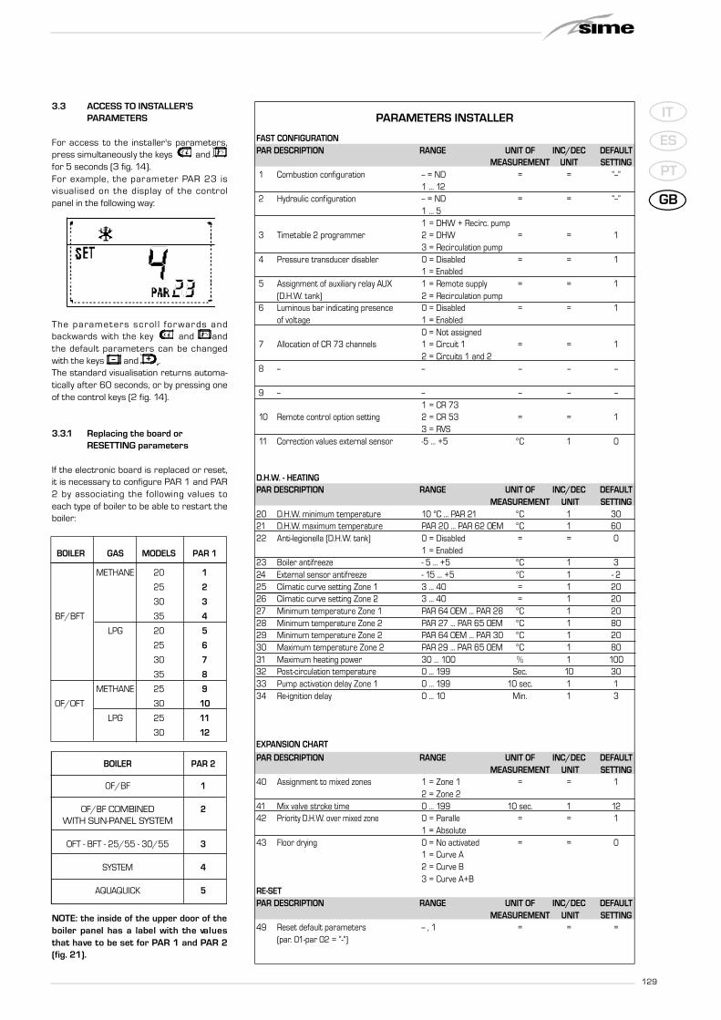
3.3 ACCESS TO INSTALLER'SPARAMETERS
For access to the installer's para m ete rs ,press simultaneously the keys andfor 5 seconds (3 fig. 14).For exa mple, the para m eter PAR 23 isvisualised on the display of the contro lpanel in the following way:
The para m ete rs scrol l fo rwa rds andb a ck wa rds with the key and a n dthe default para m ete rs can be ch a n ge dwith the keys and .The standard visualisation returns automa-tically after 60 seconds, or by pressing oneof the control keys (2 fig. 14).
3.3.1 Replacing the board or RESETTING parameters
If the electronic board is replaced or reset,it is necessary to configure PAR 1 and PAR2 by associating the fo l l owing values toeach type of boiler to be able to restart theboiler:
NOTE: the inside of the upper door of theboiler panel has a label with the va l u e sthat have to be set for PAR 1 and PAR 2(fig. 21).
PARAMETERS INSTALLER
FAST CONFIGURATIONPAR DESCRIPTION RANGE UNIT OF INC/DEC DEFAULT
MEASUREMENT UNIT SETTING1 Combustion configuration -- = ND = = “--”
1 ... 122 Hydraulic configuration -- = ND = = “--”
1 ... 51 = DHW + Recirc. pump
3 Timetable 2 programmer 2 = DHW = = 13 = Recirculation pump
4 Pressure transducer disabler 0 = Disabled = = 11 = Enabled
5 Assignment of auxiliary relay AUX 1 = Remote supply = = 1(D.H.W. tank) 2 = Recirculation pump
6 Luminous bar indicating presence 0 = Disabled = = 1of voltage 1 = Enabled
0 = Not assigned7 Allocation of CR 73 channels 1 = Circuit 1 = = 1
2 = Circuits 1 and 28 -- -- -- -- --
9 -- -- -- -- --1 = CR 73
10 Remote control option setting 2 = CR 53 = = 13 = RVS
11 Correction values external sensor -5 ... +5 °C 1 0
D.H.W. - HEATINGPAR DESCRIPTION RANGE UNIT OF INC/DEC DEFAULT
MEASUREMENT UNIT SETTING20 D.H.W. minimum temperature 10 °C ... PAR 21 °C 1 3021 D.H.W. maximum temperature PAR 20 ... PAR 62 OEM °C 1 6022 Anti-legionella (D.H.W. tank) 0 = Disabled = = 0
1 = Enabled23 Boiler antifreeze - 5 ... +5 °C 1 324 External sensor antifreeze - 15 ... +5 °C 1 - 225 Climatic curve setting Zone 1 3 ... 40 = 1 2026 Climatic curve setting Zone 2 3 ... 40 = 1 2027 Minimum temperature Zone 1 PAR 64 OEM ... PAR 28 °C 1 2028 Minimum temperature Zone 2 PAR 27 ... PAR 65 OEM °C 1 8029 Minimum temperature Zone 2 PAR 64 OEM ... PAR 30 °C 1 2030 Maximum temperature Zone 2 PAR 29 ... PAR 65 OEM °C 1 8031 Maximum heating power 30 ... 100 % 1 10032 Post-circulation temperature 0 ... 199 Sec. 10 3033 Pump activation delay Zone 1 0 ... 199 10 sec. 1 134 Re-ignition delay 0 ... 10 Min. 1 3
EXPANSION CHART
PAR DESCRIPTION RANGE UNIT OF INC/DEC DEFAULTMEASUREMENT UNIT SETTING
40 Assignment to mixed zones 1 = Zone 1 = = 12 = Zone 2
41 Mix valve stroke time 0 ... 199 10 sec. 1 1242 Priority D.H.W. over mixed zone 0 = Paralle = = 1
1 = Absolute43 Floor drying 0 = No activated = = 0
1 = Curve A2 = Curve B3 = Curve A+B
RE-SETPAR DESCRIPTION RANGE UNIT OF INC/DEC DEFAULT
MEASUREMENT UNIT SETTING49 Reset default parameters -- , 1 = = =
(par. 01-par 02 = “-“)
BOILER GAS MODELS PAR 1
METHANE 20 1
25 2
30 3
BF/BFT 35 4
LPG 20 5
25 6
30 7
35 8
METHANE 25 9
OF/OFT 30 10
LPG 25 11
30 12
BOILER PAR 2
OF/BF 1
OF/BF COMBINED 2WITH SUN-PANEL SYSTEM
OFT - BFT - 25/55 - 30/55 3
SYSTEM 4
AQUAQUICK 5

130
IT
ES
PT
GB
3.4 EXTERNALSENSOR
If there is an external sensor, the heatingsettings SET can be taken from the climaticcurves according to the external tempera-ture and, in any case, limited to with therange values described in point 3.3 (para-meters PAR 25 for zone 1 and PAR 26 forzone 2).The climatic curve to be set can be selectedfrom a value of 3 and 40 (at step 1).Increasing the steepness of the curves offig. 15 will increase the output temperatureas the external temperature decreases.
3.5 CARDFUNCTIONING
The electronic card has the following func-tions:– Antifreeze protection of the heating and
sanitary water circuits (ICE).– Ignition and flame detection system.– C o n t rol panel setting for the power and
the gas for boiler functioning.– A n t i - b l o ckfor the pump which is fed fo r
a few seconds after 24 hours of inacti-v i t y.
– A n t i f reeze protection for boilers with anaccumulation boiling unit.
– C h i m n ey sweep function which can bea c t i va ted from the control panel.
– Te mp e ra t u re which can be shifted withthe ex te rnal sensor connected.It can be set from the control panel andis active on the heating systems of bothc i rcuit 1 and circuit 2.
– M a n a gement of two independent hea-ting circuit syste m s .
– Au tomatic regulation of the ignitionp ower and maximum heating.Ad j u stments are managed auto m a t i-c a l ly by the electronic card to guara n-tee maximum fl exibility in use of th es yste m .
– I n te rface with the fo l l owing electro n i cs ystems: climatic re g u l a tor CR 53,re m ote control CR 73, th e rmal re g u l a-tor RVS and connected to a manage-ment card of a mixed zone cod.8092233.NOTE: If using CR 53 or RVS set para-meter 10 to 2 (PAR 10 = 2).
3.6 TEMPERATUREDETECTION SENSOR
Table 3 g i ves the values of the electri c a lelement ( ) obtained on the heating ands a n i ta ry wa ter sensors according to th evariations in temperature.
When the heating sensor (SM) is inte r-ru pted, the boiler will not function fo rboth services.With the D.H.W. sensor (SS) interrupted,the boiler functions but will not made thepower modulations for the D.H.W.
3.7 ELECTRONIC IGNITION
Ignition and flame detection is controlled bya single electrode on the burner which gua-rantees reaction in the case of accidentalextinction or lack of gas within one second.
3.7.1 Functioning cycle
B u rner ignition occurs within max. 10seconds after the opening of the gas valve.Ignition failure with consequent activation ofblock can be due to:
– Lack of gasThe ignition electrode persists in dischar-ging for max. 10 seconds. If the burnerdoes not ignite, the anomaly is signalled.This can happen the first time the boileris switched on after a long period of inac-tivity due to the presence of air in the gaspipesIt can be caused by a closed gas tap or bya broken valve coil (the interruption doesnot allow for opening).
– The electrode does not discharge.In the boiler, only the opening of the gasto the burner can be detected. After 10seconds the anomaly is signalled.It can be caused by an interruption in theelectrode wire or if it is incorrectly ancho-red to the connection points.Or the electrode may be earthed orstrongly worn: it must be replaced.Or the electronic card may be defective.
In the case of a sudden lack of voltage, theburner will immediately switch off. Whenvoltage returns, the boiler will automaticallystart up again.
3.8 FUMES THERMOSTATvers. OF/OFT
This is a safety measure against the returnof the fumes into the env i ronment due toan inefficient or part i a l ly blocked ch i m n ey(7 fig. 3). It reacts by blocking the functioning of thegas va lve when the fumes are continuallyfo rced back into the env i ronment, in aquantity that can be dangerous. If the boilerre p e a te d ly stops, it will be necessary toc a re f u l ly ch e ck the ch i m n ey, and to carryout all modifications and take all measuresn e c e s s a ry to re sto re it to an eff i c i e n tworking state. After every intervention car-ried outon the device, ch e ck correct func-tioning. In the case of replacement, use onlyoriginal spare parts.
TABLE 3
Temperature (°C) Resistance ( )20 12.09030 8.31340 5.82850 4.16160 3.02170 2.22980 1.669
Fig. 15
ATTENTION: curves are calculated at an ambient temperatureof 20°C. It is howev er possible to use the boiler controls tochange them by ±5°C.

131
IT
ES
PT
GB
3.9 FUMES PRESSURE SWITCHvers. BF-BFT
The pre s s u re switch is calibra ted by th emanufacturer at the following values:
5.3 - 6.3 H2O for vers. “25 BF - 25 BFT”3.6 - 4.6 H2O for vers. “30 BF”4.6 - 5.6 H2O for vers. “20 BF - 35 BFT”
which can guarantee boiler functioning alsow i th aspiration and disch a rge pipes of th emaximum length allowed.The value of the signal to the pressure swit-ch is measured by a diffe rential pre s s u regauge connected as indicated in fig. 16.
3.10 WATERFLOW GUAGE
The water flow gauge (8 fig. 4) intervenes,b l o cking burner functioning, if it dete c t sthat there is insufficient water circulating inthe primary circuit (< 450 l/h).To re s to re burner funct ioning, ch e cksystem pressure and the functioning of thepump and the flow switch, and the cleaningof the “Aqua Guard Filter System” filter.
3.11 HEAD AVAILABLETO SYSTEM
Residual head for the heating system iss h own as a function of ra te of fl ow in th egraph in fig. 17.To obtain the maximum head available tothe system, turn off the by-pass by turningthe union to the vertical position (fig. 17/a).
Fig. 16
0 200 1600140012001000800600400
PORTATA (l/h)
500
400
100
200
300
30-35
25
600
30-35
25
By-pass inseritoBy-pass escluso
Fig. 17
By-pass inserito
By-pass escluso
Fig. 17/a
FLOW RATE (l/h)
By-pass off
By-pass on
By-pass on
By-pass off

132
IT
ES
PT
GB
4.1 ADJUSTMENT OF D.H.W. FLOW RATE
To adjust the D.H.W. flow rate, use the flowrate adjuster (5 fig. 4).Remember that the flow rates and corre-sponding temperatures of use of hot water,given in section 1.3, have been obtained bypositioning the selector of the circulationpump on the maximum value.Should th e re be any reduction in th eD.H.W. flow rate, the filter installed on theinlet to the divertor valve (3 fig. 4) willneed cleaning.
4.2 GAS VALVE
The boilers are equipped standard with theSIT 845 SIMGA / HONEYWELL VK 4105M/ SIEMENS VGU 50 gas valve (fig. 18).The gas valve is set at two pressure values:maximum and minimum. Ac c o rding to the type of gas burnt, th e s ecorrespond to the values given in Table 4.The gas pre s s u res at the maximum andminimum values, are fa c to ry set. Conse-quently they must not be altered.O n ly when you switch the appliance fro mone type of gas suppl y (me thane) toa n other (butane or propane), it is perm i t-ted to alter the operating pressure.
4.3 GAS CONVERSION
This operation must be perfo rmed byauthorised personnel using original Simecomponents.To convert from natural gas to LPG or viceversa, perform the following operations (fig.19):– Close the gas cock.– Disassemble the burner manifold (3).– Replace the main nozzles (6) supplied in
a kit, inserting the copper washer (4).Use a ø 7 spanner to perform this ope-ration.
– C o n fi g u re the new fuel as indicated inpoint 4.3.1
– For calibrating the maximum and mini-mum gas pre s s u re values, see point4.3.2.
– A fter have ultimated the conve rsion ofthe boiler, please st i ck onto the casingpanel the plate showing the relevant fee-ding gas which is included into the kit.
NOTE: When reassembling componentsw h i ch you have re m oved, replace ga sseals; te st all gas connections afte rassembly using soapy water or a productmade specifically for the purpose, beingsure not to use open flame.
4.3.1 New fuel configuration
For access to the installer's para m ete rs ,press simultaneously keys and for5 seconds (3 fig. 14).
4 USE AND MAINTENANCE
12
43 5
SIT 845 SIGMA HONEYWELL VK 4105M
KEY1 Modulator2 EV1-EV2 coils3 Pressure inlet upstream4 Pressure inlet downstream5 VENT pressure test point
SIEMENS VGU 50
Fig. 19
KEY1 Swivel connection 1/2”2 Locknut 1/2”3 Burner manifold4 Washer ø 6.15 Burners6 Nozzle M67 Screw
WARNING: To ensure a perfectseal, always use the washer (4)supplied in the kit when replacingnozzles, even in burner units forwhich it is not specified.
Fig. 18
TABLE 4
Model Burner max pressure mbar Modulator current mA Burner min pressure mbar Modulator current mA
G20 (*) G30 G31 G20 (*) G30 G31 G20 (*) G30 G31 G20 (*) G30 G31
25 OF 11.0 27.7 35.7 130 165 165 1.8 4.7 4.7 0 0 0
30 OF 11.1 27.7 35.7 130 165 165 1.9 4.8 4.8 0 0 0
25 OFT 11.0 27.7 35.7 130 165 165 1.8 4.7 4.7 0 0 0
25 BF 11.8 28.5 36.5 130 165 165 2.0 4.8 4.8 0 0 0
30 BF 12.0 28.5 36.5 130 165 165 2.1 5.0 5.0 0 0 0
35 BF 13.7 28.2 36.2 130 165 165 2.2 4.5 4.5 0 0 0
20 BFT 11.0 28.5 36.5 130 165 165 1.9 4.8 4.8 0 0 0
25 BFT 11.8 28.5 36.5 130 165 165 2.0 4.8 4.8 0 0 0
(*) Max. burner pressure is guaranteed only when the supply pressure exceeds the max. burner pressure by at least 3 mbar.

133
IT
ES
PT
GB
The para m ete rs will scroll up and dow nwith the keys and .The display pane will show the values of theparameter PAR 1.If, for example, the boiler in question is a 25BF fuelled by methane, the following settingSET 2 will appear:
To change the fuel to LPG, it is necessary toset SET 6, by pressing the key .
The sta n d a rd display will auto m a t i c a l lyreturn after 10 seconds.The table below shows the SET settings toenter when the type of gas fuel is changed.
4.3.2 Adjusting valve pressure
S et maximum and minimum pre s s u re ongas valves as follows (fig. 20):– Connect the column or a manometer to
the intake downstream of the gas valve.In “BF/BFT” models, disconnect th evalve VENT pressure test point tube (5fig. 18).
– Remove the cap (1) from the modulator.– Press the key for a few seconds and
c o mp l ete ly open the hot sanita ry wa te rfaucet.
– Press the key .– Remember that rotating clockwise will
i n c rease pre s s u re while rotating anti-clockwise will diminish it.
– Adjust maximum pressure using the nut
(3) with a wrench to the maximum pres-sure value indicated in Table 4.
– Ad j u st the maximum pre s s u re befo readjusting the minimum.
– P ress the key while the sanita rywater tap is on, with the water running.
– L o ck the nut (3) in place, turn th escrew/nut (2) to the minimum pressu-re indicated in Table 4.
– Press the keys and while keepingthe hot sanita ry wa ter running all th etime, and ch e ck that the maximum andminimum pre s s u res correspond to th eset values; if necessary correct the regu-lation.
– Press the key again to quit the func-tion.
– Put the pipe back on the va lve VENTpressure test point.
– Re m ove the manomete r, re m e m b e ri n gto tighten the screw for closing the pres-sure test point.
– Put the plastic cap (1) back on the modu-l a tor and seal with a drop of coloure dsealant if necessary.
4.4 DISMANTLING THE CASING
The casing may be removed completely to
Fig. 20
KEY1 Plastic tap2 Minimum pressure adjusting nut3 Maximum pressure adjusting nut
SIT 845 SIGMA
HONEYWELL VK 4105M - SIEMENS GVU 50
BOILER GAS MODELS PAR 1
METHANE 20 1
25 2
30 3
BF/BFT 35 4
LPG 20 5
25 6
30 7
35 8
METHANE 25 9
OF/OFT 30 10
LPG 25 11
30 12
134
IT
ES
PT
GB
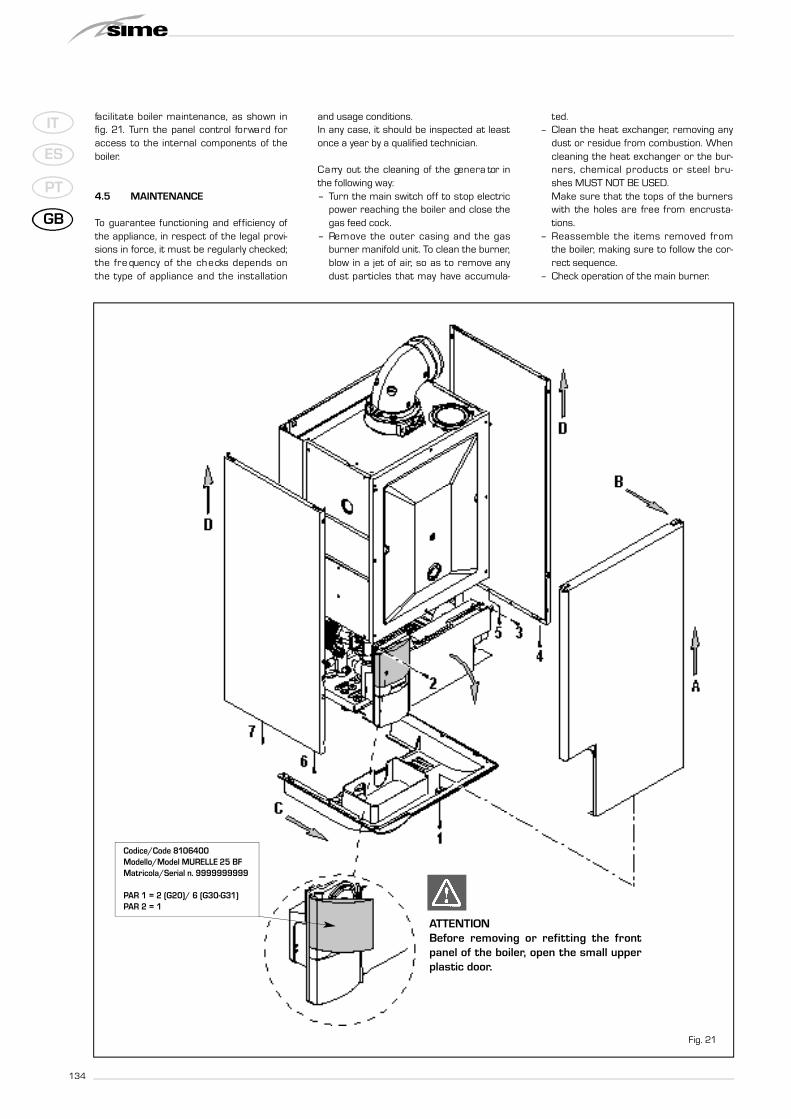
fa c i l i ta te boiler maintenance, as shown infig. 21. Tu rn the panel control fo rwa rd fo raccess to the inte rnal components of th eboiler.
4.5 MAINTENANCE
To guara n tee functioning and efficiency ofthe appliance, in respect of the legal provi-sions in force, it must be regularly checked;the fre quency of the ch e cks depends onthe type of appliance and the insta l l a t i o n
and usage conditions.In any case, it should be inspected at leastonce a year by a qualified technician.
C a rry out the cleaning of the ge n e ra tor inthe following way:– Turn the main switch off to stop electric
power reaching the boiler and close thegas feed cock.
– Re m ove the outer casing and the ga sburner manifold unit. To clean the burner,blow in a jet of air, so as to remove anyd u st particles that may have accumula-
ted.– Clean the heat exchanger, removing any
dust or residue from combustion. Whencleaning the heat exchanger or the bur-n e rs, chemical products or steel bru-shes MUST NOT BE USED.Make sure that the tops of the burnersw i th the holes are free from encru sta-tions.
– Reassemble the items re m oved fro mthe boiler, making sure to follow the cor-rect sequence.
– Check operation of the main burner.
Fig. 21
ATTENTIONBefore removing or refitting the frontpanel of the boiler, open the small upperplastic door.
Codice/Code 8106400Modello/Model MURELLE 25 BFMatricola/Serial n. 9999999999
PAR 1 = 2 (G20)/ 6 (G30-G31)PAR 2 = 1

135
IT
ES
PT
GB
– A fter assembly of all the gas connec-
tions, these must be te sted for sound-
ness, using soapy wa ter or appro p ri a te
products. DO NOT USE NAKED FLAMES.
– Do not use calcium chloride to treat the
p l a stic component during ge n e ra to r
maintenance.
4.5.1 Chimney sweep function (fig. 22)
To ch e ck boiler combustion, press th e
installer's key for a few seconds.
The ch i m n ey sweep function will switch on
and will continue for 15 minutes. From that
moment, the boiler will sta r t wo rking in
heating mode at maximum power, with cut
off at 80°C and re-ignition at 70°C.
Before activating the chimney sweep func-
tion make sure that the radiator valves or
eventual zone valves are open.
The te st can also be carried out with th e
boiler working in sanitary water mode.
For this, after activating the chimney sweep
function, open one or more hot water fau-
cets. Under these conditions, the boiler will
function at maximum power with the pri-
m a ry circuit ke pt at bet ween 60°C and
50°C. During the te st, the hot wa ter fa u-
cets must remain open.
If the key a n d a re pressed duri n g
the 15 minutes of the chimney sweep func-
tion, the boiler will be brought re s p e c t i ve ly
to maximum and minimum power.
The chimney sweep function will automa-
t i c a l ly switch off after 15 minutes or
when the key is pressed again.
4.5.2 Cleaning the filter “Aqua Guard
Filter System” (fig. 23)
To clean the filter, close the delivery/return
on/off taps, turn off the power to the con-
trol panel, remove the casing and empty the
boiler using the drain provided.
Place a container for collection underneath
the filter, unscrew the cap and proceed to
clean the filter, removing impurities and
limestone deposits.
Check the seal o-ring before reassembling
the cap with the filter.
4.5.3 Operation floor drying (fig. 23/a)
The operation floor drying keeps the fl o o r
at a pre - e stablished te mp e ra t u re pro fi l e
and it is activa ted only for those syste m s
combined with the mixed zone card code
8092233. The te mp e ra t u re pro files can
be selected by means of the installer para-
meter PAR 43:
0 = Not activated function
1 = Curve setting A
2 = Curve setting B
3 = Curve setting A + B
The turning off of the function happens
c l i cking on the button OFF (ret u rn of PA R
43 to the value 0) or auto m a t i c a l ly at th e
end of the function.
The set of the mixed zone follows the deve-
lopment of the selected curve and reaches
a maximum of 55°C. During the function all
the other heating demands are ignore d
(heating, sanita ry, antifreeze and ch i m n ey
sweep).
D u ring the functioning the display shows
the remaining days for the comp l etion of
the function (example mains digits -15 = 15
d ays lack to the end of the function). T h e
diagram fig. 23/a reports the development
of the curve.
ATTENTION:
- O b s e rve the re l evant sta n d a rds and
regulations of the floor manufacturer!
- P roper functioning is ensured only
when the plant is corre c t ly insta l l e d
( hy d raulic system, electrical insta l l a-
tion, settings)! If not observed, th e
floor might get damaged!
5
3
1
2
4
5
3
1
2
4
5
3
1
2
4
5
3
1
2
4
Fig. 23
APRE
2 2
2
Fig. 22
Fig. 23/a
TVw Flow temperature setpoint
Tag Period in days
x Start day
A Functional heating
B Floor curing heating

136
IT
ES
PT
GB
4.6 FUNCTIONING ANOMALIES
When th e re is a functioning anomaly, analarm appears on the display and the blueluminous bar becomes red.Descriptions of the anomalies with relativealarms and solutions are given below:
– FUMES DISCH A RGE ANO M A LYALARM 01 (fig. 24)OPEN BOILER (OF/OFT):The display shows “ALL 01”.The fumes th e rm o stat has inte rve n e d .The boiler stops for an enfo rced peri o dof 10 minutes. At the end of this period,the boiler re-attempts ignition. If the ano-m a ly is re p e a ted th ree t imes in 24hours, the symbol RESET starts flashing.P ress the key of the controls (2)to start up the boiler again.
SEALED BOILER (BF/BFT):The fumes thermostat has intervened. Ifthe condition causing the problem persi-sts for two minutes, the boiler stops foran enforced period of thirty minutes. Atthe end of this period, the boiler re -attempts ignition.
– LOW WATER PRESSURE ANO M A LYALARM 02 ( fig. 24 / a )If the pressure detected by the transdu-cer is lower than 0.5 bar, the boilerstops and the display shows the alarm“ALL 02”.B ring the pre s s u re back to normal bymeans of the load fa u c et (turn anti-c l o ckwise to open) until the pre s s u reindicated by the transducer is between 1and 1.5 bars.ON COMPLETION OF THE OPERAT I O N,MAKE SURE THE LOAD FAUCET IS CLO-SEDIf the load procedure has to be repeateds eve ral times, it is advisable to ch e ck
that the seal of the heating circuit isintact (check that there are no leaks).
– HIGH WATER PRESSURE ANO M A LYALARM 03 (fig. 24/b)If the pressure detected by the transdu-cer is more than 2.8 bar, the boi lerstops and the display shows anomaly“ALL 03"
– D.H.W. SENSOR ANOMALY ALARM 04( fig. 24 / c )If the D.H.W. sensor (SS) is open or
s h o rt circ u i ted, the boiler will functionbut will not modulate the power for sani-ta ry wa te r. The display will show th ealarm “ALL 04”.
– H E AT I NG SENSOR ANO M A LY ALA R M05 ( fig. 24 / d )If the heating sensor (SM) is open ors h o rt circ u i ted, the boiler will not func-tion and the display will show the alarm“ALL 05”.
– FLAME BLOCK ALARM 06 ( fig. 24 / e )If the flame control has not detected thepresence of the flame after a completeignition sequence, or for any other re a-son the card cannot “see” the flame, theboiler will stop and the display will showthe alarm “ALL 06”. Press the key of the controls (2) tostart up the boiler again.
– SA F E TY THERMOSTAT ANO M A LYALARM 07 ( fig. 24 / f )If the connection with the safety thermo-stat is inte rru pted, the boiler will sto p ;the flame control will remain waiting tobe switched off for one minute, ke e p i n gthe system pump on for that period.If, the thermostat connection is restoredwithin the minute, the boiler will start upwo rking norm a l ly again, oth e rwise it willstop and the display will show the alarm
Fig. 24/b
Fig. 24/d
2
Fig. 24/e
Fig. 24/c
Fig. 24/a
Fig. 24
2

“ALL 07”.Press the key of the controls (2) tostart up the boiler again.
– PARASITE FLAME ANO M A LY ALA R M08 ( fig. 24 / g )If the flame control section re c o g n i s e sthe presence of flames also in phaseswhen th ey should not be present, itmeans there is a breakdown in the flamedetection circuit; the boiler will stop andthe display will show anomaly “ALL 08”.
– WATER CIRC U LATION ANO M A LYALARM 09 ( fig. 24 / h )T h e re is no wa ter circulation in the pri-m a ry circuit. If the contacts of the fl owga u ge close, the sta te of anomaly isimmediately quitted.If the anomalous sta te pers i sts for onem i n u te, the boiler is enfo rc e d ly sto p p e dfor six minutes. After this time of enfor-ced inactivity, the boiler will re - a t te mptignition. If the anomaly re - a p p e a rs, th eboiler will switch off and the display willshow anomaly “ALL 09”.
– AU X I L I A RY SENSOR ANO M A LYALARM 10 ( fig. 24 / l )BOILER WITH ACCUMULATION: anomalyD.H.W. sensor. When the D.H.W. sensoris open or short circuited, the display wills h ow anomaly “ALL 10”. The boiler willfunction but will not modulate power forD.H.W.BOILER ONLY FOR HEAT I NG: antifre e z esensor anomaly for boilers w h i ch fo re-see the use of antifreeze sensors.When the sensor is open or short circui-ted, the boiler loses part of its anti-freezefunctions and the display will show ano-maly “ALL 10".BOILER COMBINED WITH SUN-PA N E LSYSTEM: anomaly D.H.W. input sensor.When the sensor is open or short circui-ted, the boiler loses the sun-panel func-tion and the display will show anomaly“ALL 10".
– M O D U LATOR ANO M A LY ALARM 11( fig. 24 / m )The modulator is not connected.When dur ing funct ioning the boilerd etects zero current to the modulato r,the display will show anomaly “ALL 11”.The boiler will function at minimumpower and the anomaly will be de-acti-vated when the modulator is reconnec-ted or when the burner stops working.
– CO N F I G U R ATION ANO M A LY ALA R M12 ( fig. 24 / n )A n o m a ly in the SEALED/OPEN confi g u-ration. There may be a conflict betweenthe values set by the installer for PAR 1and the self-detection carried out by thecard causes the activation of the alarm:the boiler will not function and the displaywill show anomaly “ALL 12”.
Reset PAR 1 to de-activate the alarm.
137
IT
ES
PT
GB
Fig. 24/l
Fig. 24/m
Fig. 24/n
2
Fig. 24/g
Fig. 24/h
Fig. 26/f
138
IT
ES
PT
GB
USER INSTRUCTIONS
WARNINGS– In case of fault and/or incorrect equipment operation, deactivate it, without making any repairs or taking any direct
action. Apply only to qualified technical personnel.
– Boiler installation and any other assistance and/or maintenance activity must be carried out by qualified personnel
persuant to Standard CEI 64-8. Under no circumstances, the devices sealed by the manufacturer can be tampered
with.
– It is absolutely prohibited to block the intake grilles and the aeration opening of the room where the equipment is
installed.
– The manufacturer shall not be held liable for any damage caused by improper use of the appliance.
LIGHTING AND OPERATION
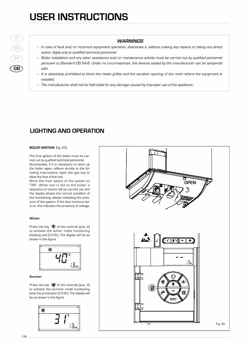
BOILER IGNITION (fig. 25)
The first ignition of the boiler must be car-ried out by qualified technical personnel.S u c c e s s i ve ly, if it is necessary to sta rt upthe boiler again, adhere st ri c t ly to the fo l-l owing inst ructions: open the gas tap toallow the flow of the fuel.M ove the main switch of the system to“ON”. When fuel is fed to the boi ler, asequence of checks will be carried out andthe display shows the normal condition ofthe functioning, always indicating the pres-sure of the system. If the blue luminous baris on, this indicates the presence of voltage.
Winter
Press the key of the controls (pos. 2)to activa te the winter mode functioning(heating and D.H.W.). The display will be asshown in the figure.
Summer
Press the key of the controls (pos. 2)to activa te the summer mode functioning(only the production D.H.W.). The display willbe as shown in the figure.
APRE
2
Fig. 25
OPEN

139
IT
ES
PT
GB
R E G U LATION OF THE WATER TEMPERA-TURE FOR HEATING (fig. 26)
To set the te mp e ra t u re of the wa ter fo rheating, press the key of the contro l s(2).The first time the key is pressed, the SET ofheating circuit 1 is selected. The secondtime it is pressed, the SET of heating circuit2 is selected. The display will be as shownin the figure.C h a n ge the values with the keyand . Standard visualisation will returnto the display by pressing the key again,or after 10 seconds if no key is pressed.
Regulation of the external sensor
If an external sensor is installed, the valueof the output temperature is automaticallychosen by the system, which quickly adjuststhe env i ro n m e n tal te mp e ra t u re on th ebasis of the external temperature.If you wish to change the value of the tem-perature, increasing or decreasing that cal-c u l a ted auto m a t i c a l ly by the electro n i ccard, proceed as indicated in the precedingp a ra graph. The level of va rious corre c t i o nof a value of temperature proportional cal-culated. The display will be as shown in fig.26/a.
REGULATION OF THE D.H.W.TEMPERATURE (fig. 27)
To set the desired te mp e ra t u re D.H.W. ,p ress the key of the controls (pos. 2).The display will be as shown in the figure.C h a n ge the values with the keyand .The display will return to the stan-d a rd visualisation by pressing the keyagain, or after 10 seconds if no key is pres-sed.
TO SWITCH OFF THE BOILER (fig. 25)
In the case of a short absence, press th ekey of the controls (pos. 2). The displaywill be as shown in the fi g u re 25. In th i sway, leaving the electricity and the fuel sup-ply connected, the boiler is protected fromf ro s t and from the pump becomingblocked.If the boiler is not used for a pro l o n ge dp e riod, it is advisable to disconnect th eelectricity supply, by switching off the mainswitch of the system, and to close the gastap and, if low temperatures are expected,to comp l ete ly empty the hy d raulic circ u i t sto avoid pipes being bro ken by the fo rm a-tion of ice in the pipes.
2
Fig. 26
Fig. 26/a
2
Fig. 27
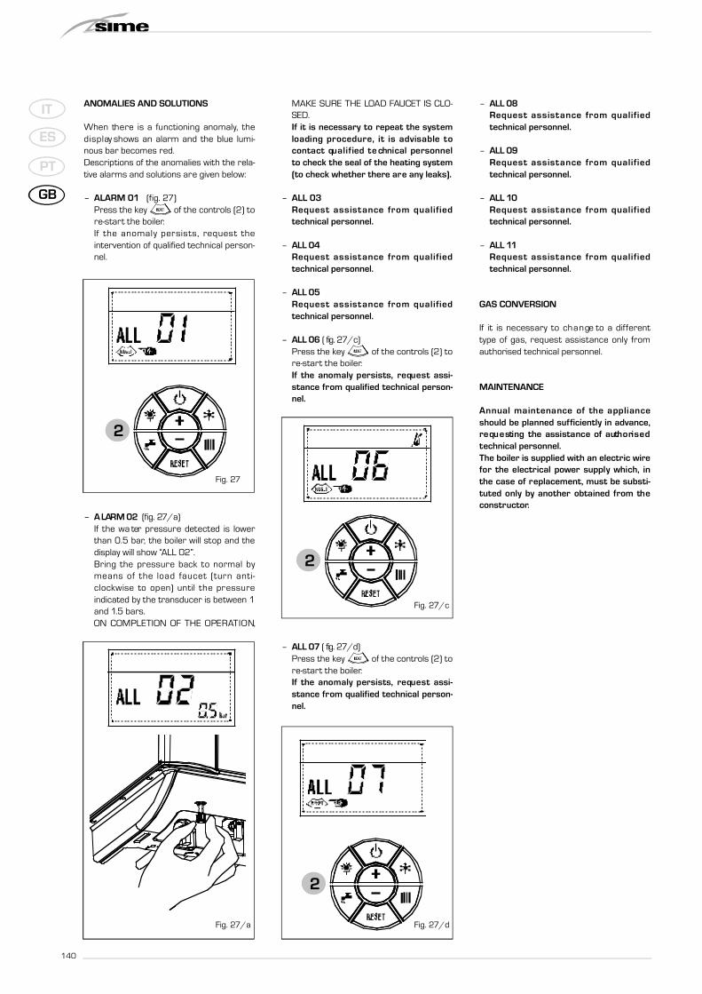
ANOMALIES AND SOLUTIONS
When th e re is a functioning anomaly, th ed i s p l ay shows an alarm and the blue lumi-nous bar becomes red.Descriptions of the anomalies with the rela-tive alarms and solutions are given below:
– ALARM 01 (fig. 27)Press the key of the controls (2) tore-start the boiler.If the anomaly pers i sts, re qu e st th eintervention of qualified technical person-nel.
– A LARM 02 ( fig. 27 / a )If the wa ter pre s s u re dete c ted is lowe rthan 0.5 bar, the boiler will stop and thedisplay will show “ALL 02”.B ring the pre s s u re back to normal bymeans of the load fa u c et (turn anti-c l o ckwise to open) until the pre s s u reindicated by the transducer is between 1and 1.5 bars.ON COMPLETION OF THE OPERAT I O N,
MAKE SURE THE LOAD FAUCET IS CLO-SED.If it is necessary to repeat the systemloading pro c e d u re, it is advisable toc o n tact qu a l i fied te chnical pers o n n e lto check the seal of the heating system(to check whether there are any leaks).
– ALL 03Re qu e st assistance from qu a l i fi e dtechnical personnel.
– ALL 04Re qu e st assistance from qu a l i fi e dtechnical personnel.
– ALL 05Re qu e st assistance from qu a l i fi e dtechnical personnel.
– ALL 06 ( fig. 27 / c )Press the key of the controls (2) tore-start the boiler.If the anomaly pers i sts, re qu e st assi-stance from qualified technical person-nel.
– ALL 07 ( fig. 27 / d )Press the key of the controls (2) tore-start the boiler.If the anomaly pers i sts, re qu e st assi-stance from qualified technical person-nel.
– ALL 08Re qu e st assistance from qu a l i fi e dtechnical personnel.
– ALL 09Re qu e st assistance from qu a l i fi e dtechnical personnel.
– ALL 10Re qu e st assistance from qu a l i fi e dtechnical personnel.
– ALL 11Re qu e st assistance from qu a l i fi e dtechnical personnel.
GAS CONVERSION
If it is necessary to ch a n ge to a diffe re n ttype of gas, re qu e st assistance only fro mauthorised technical personnel.
MAINTENANCE
Annual maintenance of the applianceshould be planned sufficiently in advance,re qu e sting the assistance of auth o ri s e dtechnical personnel.The boiler is supplied with an electric wirefor the electrical power supply which, inthe case of replacement, must be substi-t u ted only by another obtained from th econstructor.
2
2
Fig. 27/c
2
Fig. 27
Fig. 27/a Fig. 27/d
GB
PT
ES
IT
140


Fonderie Sime S.p.A - Via Garbo, 27 - 37045 Legnago (Vr)Tel. + 39 0442 631111 - Fax +39 0442 631292 - www.sime.it