
DLX - DLXB MF/M - Etatron GB
29
DLX - DLXB MF/M UNI EN ISO 9001-2008 www.etatronds.com NORME DI INSTALLAZIONE, USO E MANUTENZIONE OPERATING INSTRUCTIONS AND MAINTENANCE IT UK
-
Upload
khangminh22 -
Category
Documents
-
view
0 -
download
0
Transcript of DLX - DLXB MF/M - Etatron GB

DLX - DLXB MF/M
UNI EN ISO 9001-2008
www.etatronds.com
NORME DI INSTALLAZIONE, USO E MANUTENZIONE
OPERATING INSTRUCTIONS AND MAINTENANCE
IT
UK
• 28 •
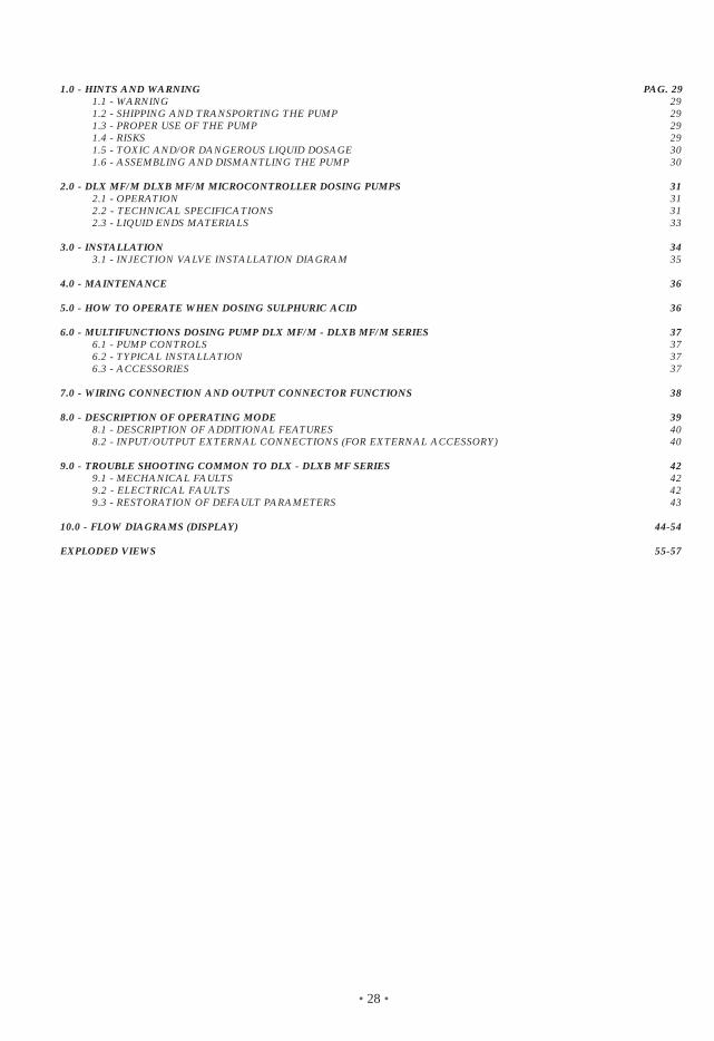
1.0 - HINTS AND WARNING PAG. 291.1 - WARNING 291.2 - SHIPPING AND TRANSPORTING THE PUMP 291.3 - PROPER USE OF THE PUMP 291.4 - RISKS 291.5 - TOXIC AND/OR DANGEROUS LIQUID DOSAGE 301.6 - ASSEMBLING AND DISMANTLING THE PUMP 30
2.0 - DLX MF/M DLXB MF/M MICROCONTROLLER DOSING PUMPS 312.1 - OPERATION 312.2 - TECHNICAL SPECIFICATIONS 312.3 - LIQUID ENDS MATERIALS 33
3.0 - INSTALLATION 343.1 - INJECTION VALVE INSTALLATION DIAGRAM 35
4.0 - MAINTENANCE 36
5.0 - HOW TO OPERATE WHEN DOSING SULPHURIC ACID 36
6.0 - MULTIFUNCTIONS DOSING PUMP DLX MF/M - DLXB MF/M SERIES 376.1 - PUMP CONTROLS 376.2 - TYPICAL INSTALLATION 376.3 - ACCESSORIES 37
7.0 - WIRING CONNECTION AND OUTPUT CONNECTOR FUNCTIONS 38
8.0 - DESCRIPTION OF OPERATING MODE 398.1 - DESCRIPTION OF ADDITIONAL FEATURES 408.2 - INPUT/OUTPUT EXTERNAL CONNECTIONS (FOR EXTERNAL ACCESSORY) 40
9.0 - TROUBLE SHOOTING COMMON TO DLX - DLXB MF SERIES 429.1 - MECHANICAL FAULTS 429.2 - ELECTRICAL FAULTS 429.3 - RESTORATION OF DEFAULT PARAMETERS 43
10.0 - FLOW DIAGRAMS (DISPLAY) 44-54
EXPLODED VIEWS 55-57

• 29 •
1.0 - HINTS AND WARNINGS
Please read the warning notices given in this section very carefully, because they provide important informationregarding safety in installation, use and maintenance of the pump.• Keep this manual in a safe place, so that it will always be available for further consultation.• The pump complies with EEC directives No.89/336 regarding "electromagnetic compatibility" and No.73/23regarding "low voltages", as also the subsequent modification No.93/68.
N.B. The pump has been constructed in accordance with best practice. Both its life and it electrical andmechanical reliability will be enhanced if it is correctly used and subjected to regular maintenance.
1.1 - WARNING: Any intervention or repair to the internal parts of the pump must be carried out by qualified and authorizedpersonnel. The manufacturers decline all responsibility for the consequences of failure to respect this rule.
GUARANTEE: 1 year (the normal wearing parts are excluded, i.e.: valves, nipples, tube nuts, tubing, filterand injection valve). Improper use of the equipment invalidates the above guarantee. The guarantee is ex-factory or authorized distributors.
1.2 - SHIPPING AND TRANSPORTING THE PUMPThe pump should always be moved in a vertical (and never in a horizontal) position. No matter what the meansof transport employed, delivery of the pump, even when free to the purchaser's or the addressee's domicile, isalways at the purchaser's risk. Claims for any missing materials must be made within 10 (ten) days of arrival,while claims for defective materials will be considered up to the 30th (thirtieth) day following receipt. Return ofpumps or other materials to us or the authorized distributor must be agreed beforehand with the responsiblepersonnel.
1.3 - PROPER USE OF THE PUMP• The pump should be used only for the purpose for which it has been expressly designed, namely the dosingof liquid additives. Any different use is to be considered improper and therefore dangerous.The pump should nottherefore be used for applications that were not allowed for in its design. In case of doubt, please contact ouroffices for further information about the characteristics of the pump and its proper use.The manufactures cannot be held responsible for damage deriving from improper, erroneous or unreasonableuse of the pump.
1.4 - RISKS• After unpacking the pump, make sure it is completely sound. In case of doubt, do not use the pump and con-
tact qualified personnel. The packing materials (especially bags made of plastics, polystyrene, etc.) shouldbe kept out of the reach of children: they constitute potential sources of danger.
• Before you connect the pump, make sure that the voltage ratings, etc., correspond to your particular powersupply. You will find these values on the rating plate attached to the pump.
• The electrical installation to which the pump is connected must comply with the standards and good prac-tice rule in force in the country under consideration.
• Use of electrical equipment always implies observance of some basic rules: In particular:1 - do not touch the equipment with wet or damp hands or feet;2 - do not operate the pump with bare feet (Example: swimming pool equipment);3 - do not leave the equipment exposed to the action of the atmospheric agents;4 - do not allow the pump to be used by children or unskilled individuals without supervision;• In case of breakdown or improper functioning of the pump, switch off, but do not touch. Contact our techni-
cal assistance for any necessary repairs and insist on the use of original spares. Failure to respect this con-dition could render the pump unsafe for use.
• When you decide to make no further use of an installed pump, make sure to disconnect it from the powersupply.
Before carrying out any service on the item, check:1. Disconnect the pins from the mains or by means of a two poles switch with 3 mm minimum distance
between the contacts. (Fig. 4).2. Relieve all the pressure from the pump head and injection tube.3. Drain or flush all dosing liquid from the pump head. This operation can also be done with the pump dis-
connected from the plant by turning the pump upside-down for 15 to 30 seconds and without connectingthe tubing to the nipples: if this operation is not possible, dismount and remount the pump head usingthe four mounting screws.
In event of possible losses in the hydraulic system of the pump (breakage of the "O" ring gasket, the valvesor the hoses) the pump should immediately be brought to a stop, emptying and depressurizing the deliveryhose while taking all due safety precautions (gloves, goggles, overalls, etc.).
EN
GLIS
H

• 30 •
1.5 - TOXIC AND/OR DANGEROUS LIQUID DOSAGETo avoid risk from contact with the hazardous liquids or toxic fumes, always adhere to the notes in this instruc-tion manual: • Follow the instructions of the dosing liquid manufacturer. • Check the hydraulic part of the pump and use it only if it is in perfect condition. • Use only the correct materials for the tubing, valves and seals to suit the liquid to be dosed; where possible
shield the tubing with PVC conduit. • Before disconnecting the metering pump, make sure to flush out and neutralize the pump head with the
proper reagent liquid.
1.6 - ASSEMBLING AND DISMANTLING THE PUMP
1.6.1 - ASSEMBLYAll metering pumps are normally supplied fully assembled. For greater clarity, please consult the exploded viewof the pump appended at the end of the manual, which shows all the pump details and a complete overview ofall the pump components. These drawings are in any case quite indispensable whenever defective parts haveto be re-ordered. For the same purpose, the appendix also contains other drawings showing the hydraulic parts(pump head and valves).
1.6.2 - DISMANTLEMENTProceed as follows before you dismantle the pump or before performing any other operation on it:1. Disconnect the pins from the mains or by means of a two poles switch with 3 mm minimum distance between
the contacts. (Fig. 4).2. Relieve all the pressure from the pump head and injection tube.3. Drain or flush all dosing liquid from the pump head. This operation can also be done with the pump discon-
nected from the plant by turning the pump upside-down for 15 to 30 seconds and without connecting thetubing to the nipples: if this operation is not possible, dismount and remount the pump head using the fourmounting screws. (Fig. 10).
This operation calls for special attention, and you should therefore consult the drawings in Appendix andChapter 1.4“RISKS” before you commence work.
Electrical and Electronic Equipment (EEE) can contain materials harmful to health and the environment, and therefore issubject to separate waste collection: it must be disposed of at appropriate waste collection points or returned to thedistributor against purchase of new equipment of similar type or having the same functions.The directive mentioned above, to which make reference for further details, provides for punitive actions in caseof illegal disposal of such waste.
(UK) WASTE OF ELECTRICAL AND ELECTRONIC EQUIPMENT DIRECTIVE (WEEE, RAEE in Italy) 2002/96/ECAND SUBSEQUENT AMENDMENT 2003/108/ECThe marking shown below indicates that the product cannot be disposed of as part of normal household waste.
• 31 •
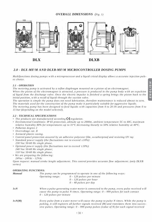
OVERALL DIMENSIONS (Fig. 1)
2.0 - DLX-MF/M AND DLXB-MF/M MICROCONTROLLER DOSING PUMPS
Multifunctions dosing pumps with a microprocessor and a liquid cristal display allows a accurate injection puls-es choice.
2.1 - OPERATIONThe metering pump is activated by a teflon diaphragm mounted on a piston of an electromagnet.When the piston of the electromagnet is attracted, a pressure is produced in the pump body with an expulsionof liquid from the discharge valve. Once the electric impulse is finished a spring brings the piston back to theinitial position, with a recall of liquid through the suction valve.The operation is simple the pump does not need lubrication, therefore maintenance is reduced almost to zero.The materials used for the construction of the pump make it particularly suitable for aggressive liquids.The metering pump has been designed to feed liquids with capacities from 0 to 20 l/h and pressures from 0 to15 bar (depending on the model selected).
2.2 - TECHNICAL SPECIFICATIONS• The products are manufactured according regulation.• Enviromental Conditions: IP 65 protection, altitude up to 2000m, ambient temperature 5C to 40C, maximum
relative humidity 80% for temperatures up to 31°C decreasing linearly to 50% relative humidity at 40°C.• Pollution degree 2• Overvoltage cat. II• Antiacid plastic casing.• Control panel protection assured by an adhesive polyester film, weatherproof and resisting UV ray• Standard power supply (the fluctuations not to exceed ±10%):
230 Vac 50-60 Hz single phase.• Optional power supply (the fluctuations not to exceed ±10%):
240 Vac 50-60 Hz single phase;110 Vac 50-60 Hz single phase.
• We are preparing the following:24Vac - 24Vdc - 12Vdc
Upon request: manual stroke lenght adjustment. This control provides accurate flow adjustment. (only DLXBseries)
OPERATING FUNCTIONS:Manual The pump can be programmed to operate in one of the following ways:
Operating range: 0 – 120 pulses per minute0 – 120 pulses per hour0 – 48 pulses per day
1xN When a pulse generating water meter is connected to the pump, every pulse received willcause the pump to pulse N times. Operating range: 0 – 999 pulses for each contact0 – 120 pulses per minute
1xN(M) Every pulse from a water meter will cause the pump to pulse N times. While the pump ispulsing, it still registers all further signals received (M) and translates them into succes-sive pulses. Operating range: 0 – 999 pump pulses (value of N) for each signal received
EN
GLIS
H
DLX DLXB

• 32 •
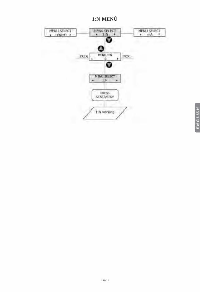
1 : N Every N number of signals received on the connector, the pump supplies an injection0-999 pulses for each contact
mA The pump doses in proportional way to the power signalOperating range: 0 – 20 mA pulses per minute
0-120 pump pulses per minuteMinimum and maximum cutoff points are adjustable: Stop/Continue dosing
PPM The pump can dose directly in PPM. User can set the following parameters:Water meter liter/contacts 0.1, 0.25, 0.5, 1, 2.5, 5, 10, 25, 50, 100, 250, 500, 1000. cc/injec-tion 0.00 - 20.00 Concentration of solution (%) - PPM 0.1 – 20.000
ACCESSORY FUNCTIONS:
FLOW ALARM The pump controls by mean of a device called flow sensor if the injection are really done and will worn the user in case of the selected conditions are not achived. The user will see a yellow led light-on and the intervention of the service relay and the sound of thebuzzer.Reference injections 0-100; Max injection difference 0-100.
LOSS OF POWER In case of loss of power for a period not above 24 hours, in which the internal battery will remane charged, the internal circuit will show such condition with a yellow led light and the intervention of the of the service relay.
ALARM FOR TOO During functions 1xN(M) and PPM the pump controls the number of injection that must be done.MANY INCOMING In case that, the number of injections are higher then 4xN (N are the number of pulses toPULSES be done for every incoming signal) the pump will generate an alarm wich will light on the
yellow led and operates the service relay.
OUTPUT SERVICE This relay will be closed when a loss of power and/or an excessive amount of pulses willRELAY be present or flow alarm will arrive.
Characteristic: 1 pole - 250V a.c. 5A (resistive load)
BUZZER Audible alarm for missed pump pulses can be Enabled / Disabled
CLOCK Date and timeday/month/yearhour/minutesClock holds its settings in the case of power failure of up to 2 hours. Prior to initial use,pump should be powered for 12 Hrs to precharge internal battery
REMOTE CONTROL Ability to control the pump (START / STOP) from normal or reversed polarity remote loca-tion
TIMER Built-in weekly and daily timer 8 cycles of daily on/off operation. Setting to the minute
LANGUAGE Menu languages choice: Italian / English
Serial line This connector (Pos. 4 - see chapter 7.0) is used only to update the software, although it RS232 has an input to totally reset the pump only if it goes to permanent block.
Pulses characteristic• Pulse duration mSec.:80 (user can not change it)• Max pulses frequency / minute: 120• Max pulses frequency / hour: 120• Max pulses frequency / day: 48
Input connectors characteristic• Min contact duration mSec.:10• Max contact number / second:40
“mA” characteristic / function• Ampere meter accuracy: 0,1 mA• Setting mA (1) SET 1: 4,0 mA

• 33 •
• Setting mA (2) SET 2: 20,0 mA• Pulses/minute (1) SET 1: 0• Pulses/minute (2) SET 2: 100÷120• Below mA (1) SET 1: Stop• Above mA (2) SET 2: Stop
Remote control: Closing /opening delay contact: 3 seconds - Polarity: Normal
2.3 - LIQUID ENDS MATERIALS- DIAPHRAGM: PTFE- PUMP HEAD: Polypropylene; upon request: PVC, 316 Stainless Steel, PTFE, PVDF. - NIPPLES: polypropylene- FILTER: polypropylene- INJECTION NIPPLE: polypropylene- SUCTION HOSE: PVC - flexible- DISCHARGE HOSE: polyethylene- VALVES: “lip”type FPM (Viton®) upon request available in EPDM (Dutral®), NBR, Silycon.- “Ball Check” VALVES upon request type in SS 316 and Glass PYREX. Available with Spring Return and
“KALREZ”Valve.- SEALS: FPM (Viton®) upon request EPDM (Dutral®), NBR, Silycon, PTFE only for ball checks valves
The diagrams of fig. 3 indicate max metering pump flow variation in relation to the working pressure in theplant; the diagrams also include injection valve losses. I.V.P.Due to production requirements the technical characteristics of our equipment at maximum ratings can varywith a tolerance of 5% which must be taken into account when choosing the type of pump.
Fig. 3
MAIN FEATURESTipo Type
Portata maxMax flow
Pressione maxMax press
Max imp./min.Max imp./min.
Dosaggio per imp.Output per stroke
CorsaStroke
Altez. aspiraz.Suction height
Aliment. elettr. standardStandard power supply
Potenza ass.Power comp.
Corrente ass.Current comp.
Peso nettoNet weight
l/h bar ml mm m Volts - Hz Watts Ampere kg
1-15 1 15 120 0.14 0.80 2.0 230 V 50-60 Hz 37 0.16 2.3
2-10 2 10 120 0.28 0.80 2.0 230 V 50-60 Hz 37 0.16 2.3
5-7 5 7 120 0.69 1.00 2.0 230 V 50-60 Hz 37 0.16 2.3
5-12 5 12 120 0.69 1.00 2.0 230 V 50-60 Hz 58 0.25 2.9
8-10 8 10 120 1.11 1.40 2.0 230 V 50-60 Hz 58 0.25 2.9
15-4 15 4 120 2.08 2.20 2.0 230 V 50-60 Hz 58 0.25 2.9
2-20 2 20 120 0.28 1.00 2.0 230 V 50-60 Hz 58 0.25 2.9
EN
GLIS
H
i.v.p.
bar20
10
15
5
00 5 10 15 20 l/h
2-10
5-7
2-20
5-12
8-10
15-420-3
1-15
20-3 20 3 120 2.60 2.20 2.0 230 V 50-60 Hz 58 0.25 2.9
Fig. 2
viola.massimiliano
viola.massimiliano
viola.massimiliano
viola.massimiliano
viola.massimiliano
Tipo Type Portata max Max flow Pressione max Max press Max imp./min. Max imp./min. Dosaggio per imp. Output per stroke Corsa Stroke Altez. aspiraz. Suction height Aliment. elettr. standard Standard power supply Potenza ass. Power comp. Corrente ass. Current comp. Peso netto Net weight l/h bar ml mm m Volts - Hz Watts Ampere kg 1-15 1 15 120 0.14 0.80 2.0 230 V 50-60 Hz 37 0.16 2.3 2-10 2 10 120 0.28 0.80 2.0 230 V 50-60 Hz 37 0.16 2.3 5-7 5 7 120 0.69 1.00 2.0 230 V 50-60 Hz 37 0.16 2.3 5-12 5 12 120 0.69 1.00 2.0 230 V 50-60 Hz 58 0.25 2.9 8-10 8 10 120 1.11 1.40 2.0 230 V 50-60 Hz 58 0.25 2.9 15-4 15 4 120 2.08 2.20 2.0 230 V 50-60 Hz 58 0.25 2.9
viola.massimiliano
viola.massimiliano
viola.massimiliano
viola.massimiliano
viola.massimiliano
viola.massimiliano
viola.massimiliano
viola.massimiliano
viola.massimiliano
viola.massimiliano
viola.massimiliano
viola.massimiliano

• 34 •
3.0 - INSTALLATION
a. - Install the pump in a dry place and well away from sources of heat and, in any case, at environmental tem-peratures not exceeding 40°C. The minimum operating temperature depends on the liquid to be pumped,bearing in mind that it must always remain in a liquid state.
b. - Carefully observe the regulations in force in the various countries as regards electrical installations (Fig.4).When the supply cable is devoid of a plug, the equipment should be connected to the supply mains bymeans of a two-poles switch having a minimum distance of 3 mm between the contacts. Before access-ing any of the electrical parts, make sure that all the supply circuits are open.
Fig. 4
c.- Locate the pump as shown in fig. 5 bearing in mind that it may be installed either below or above the levelof the liquid to be dosed, though the level difference should not exceed 2 meters. When the process plant inwhich the pump is installed is operating at atmospheric pressure (no back pressure) and the chemical tankis situated above the plant (Fig. 6), the condition of the injection valve should be checked at regular inter-vals, because excessive wear and tear could cause additive to drip into the plant even when the pump is shutdown. If the problem persist, install a properly calibrate counter-pressure valve (C) between injection pointand the valve. In the case of liquids that generate aggressive vapours, do not install the pump above thestorage tank unless the latter is hermetically sealed.
d. - The discharge nipple will always remain in the upper part of the pump. The suction nipple, which serves toattach the hose (with filter) leading into the chemical tank, will therefore always be situated in the lower partof the pump.
Fig. 7
e. - Remove the protection caps from the two nipples, slide the hoses over the connectors, pushing them righthome, and then fix them with appropriate tube nuts. (Fig. 7).
Fig. 6Fig. 5
C
BLUE
BROWN
YELLOW/GREEN

• 35 •
Fig. 8Whenever the pump is dismantled from the pipework, you will be well advised to replace the caps on theconnectors to avoid residual liquid being spilled. Before attaching the delivery hose to the plant, prime themetering pump by going through the sequence shown in Fig. 8. Before finalizing the installation of the dis-charge hose, make sure that the pump strokes will not cause it to move and bump into rigid bodies. In caseof priming difficulties, use a normal syringe to suck liquid from the discharge nipple while the pump is inoperation, continuing until you actually see the liquid rise in the syringe. Use a short length of suction hoseto connect the syringe to the discharge nipple. In case of a pump equipped with an air bleed valve, unscrewthe air relief valve B up to all the air in the pump head will be out.
f. - Try to keep both the suction and discharge hose as straight as possible, avoiding all unnecessary bends.g. - Select the most appropriate injection point on a pipe of the plant to be treated and there fit a 3/8" female gas
thread connector (similar to BSPm). This connector is not supplied with the pump. Screw the injection valveto the gas connector, inserting a gasket as shown in Fig. 9. Then connect the discharge hose to the conicalconnector on the injection valve and fix it with the supplied tube nut G. The injection valve also acts as noreturn valve by means of a cylinder sleeve (elastomer, standard supplied in Viton).
N.B. The sleeve D must not be removed.
3.1 - INJECTION VALVE INSTALLATION DIAGRAM Fig. 9
A - Pipework C - Injection valveM - Conical connector for attaching the
discharge hoseN - 3/8" female steel gas thread connectorG - Hose tube nutT - Polyethylene hoseD - Cylinder sleeve (no return valve)
B B B
Fig. 9
3.2 - MANUAL STROKE LENGHT ADJUSTMENT - (upon request only for DLXB)
- press and turn the knob (1) up to the stroke lenght adjustement required.
1
EN
GLIS
H

• 36 •
4.0 - MAINTENANCE
1. Periodically check the chemical tank level to avoid the pump operating without liquid. This would not dam-age the pump, but may damage the process plant due to lack of chemicals.
2. Check the pump operating condition at least every 6 months, pump head position, screws, bolts and seals;check more frequently where aggressive chemicals are pumped, especially:- pulse and power L.E.D.;- the additive concentration in the pipework; a reduction of this concentration could be caused by the wear-ing of the valves, in which case they need to be replaced (Fig. 10) or by the clogging of the filter which thenhas to be cleaned as in point 3 here below.
Fig. 10
3. The Company suggests periodically cleaning off the hydraulic parts (valves and filter). We cannot say howoften this cleaning should be done as it depends on the type of application, we also cannot suggest whatcleaning agent to use as this will depend on the additive used.
Operating suggestions when dosing sodium hypochlorite (most frequent case):a - disconnect the pins from the mains or by means of a onnipolar switch with 3 mm minimum distance betweenthe contact.b - disconnect discharge hose from pipework; c - remove the suction hose (with filter) from the tank and dip it into clean water;d - switch on the metering pump and let it operate with water for 5 to 10 minutes;e - switch OFF the pump, dip the filter into a hydrochloric acid solution and wait until the acid finishes
cleaning; f - switch ON the pump again and operate it with hydrochloric acid for 5 minutes in a closed-circuit, with
suction and discharge hose dipped into the same tank;g - repeat the operation with water;h - re-connect the metering pump to the pipework.
5.0 - HOW TO OPERATE WHEN DOSING SULPHURIC ACID (50% MAX FOR STD PUMP)
In this case it is essential to bear in mind the following:1. replace PVC crystal suction hose with polyethilene discharge hose; 2. empty any residual water from the pump head beforehand.Warning: if the water mixes with sulphuric acid it can produce a large quantity of gas with consequent over-heating of the area causing damage to valves and pump head.This operation can also be done with the pump disconnected from the plant by turning the pump upside-downfor 15 to 30 seconds and without connecting the hose to the nipples; if impossible, dismount and remount thepump head (Fig. 10) using the four mounting screws.
WARNING: to tightening the four screws, use
wrench to 1,8N x m.a dynamometric screw driver, set the torque

Fig. 11
6.0 - MULTIFUNCTIONS DOSING PUMP DLX MF/M; DLXB MF/M SERIESMultifunctions dosing pump with a microcontroller and a LCD (liquid cristal display) allows an accurate injectionpulses choice.
6.1 - PUMP CONTROLS (Fig. 11)1 - Increasing values button - movement in the programming menu2 - "Next program" button3 - Decreasing values button - movement in the programming menu4 - "Yellow" LED flow sensor alarm/max allowed pulse difference5 - "Red" LED injection pulse flashing6 - "green/red" LED pump fed/stand by7 - LCD display8 - "Previous program" button9 - Activation/Deactivation metering button
6.2 - TYPICAL INSTALLATION (Fig.12)A Injection valveB Power supplyC FilterD Floating level switchF Water meter connector - mA inputG Level switch connector - flow alarm K Water meterI Chemical tankM Relay output connectorO RS232 - Reset connectorQ Flow alarmV Process tank
6.3 - ACCESSORIES• 1 flexible PVC suction hose,
transparent crystal type, length 2 m;• 1 semirigid polyethylene hose,
white, length 2 m;• 1 injection valve 3/8 BSP m;• 1 filter;• 1 instructions/operating booklet.
Fig. 12
DLX-MF/M • DLXB-MF/M
123
4
5
6
7
8
9
• 37 •
EN
GLIS
H

• 38 •
7.0 - WIRING CONNECTION AND OUTPUT CONNECTOR FUNCTIONS
Female service connector wire assembly Functions and technical informations
Relay service output connection(valid only power is on)Configuration:Pin 1 = Normally open
“ 2 = Normally closed“ 3 = Common
= Not connected
Level probe connection - remote control;Flow sensorConfiguration :Pin 1 = Flow sensor
“ 2 = Flow sensor“ 3 = Level probe wire (remote control)“ 4 = Level probe wire (remote control)
Pulse emitting water meter connection - mA inputConfiguration :Pin 1 = (+) mA signal
“ 2 = (-) mA signal“ 3 = Water meter signal wire“ 4 = Water meter signal wire
RS 232 - Reset connectionConfiguration :Pin 1 = tx - transmit
“ 2 = rx - receive“ 3 = gnd - ground“ 4 = Reset
The external connector pos. 4 is used only to update the software but it has input to totally reset the equipment. This isinfact protected by external problems of such entity which could compromise its proper working.Only in such situation the pump could go in protection (permanent block) but it is possible to reset its working by linkingfor a while, connector Pins 3 and 4. Any damage can be stand by the microcontroller as it is protected by (over writing) acci-dental caused by such problems.
• 39 •
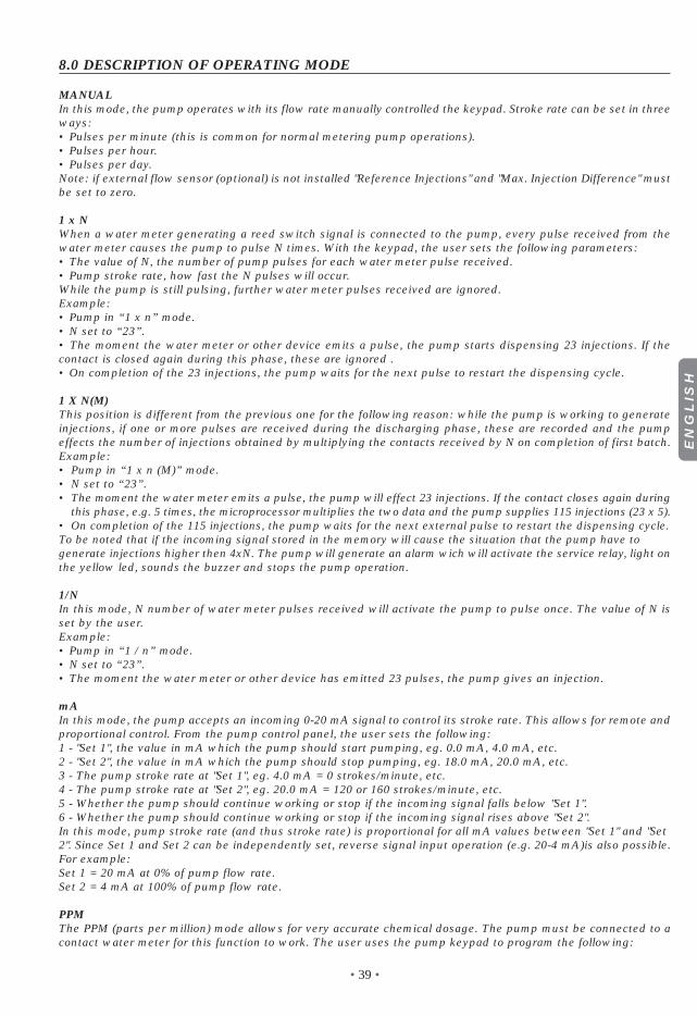
8.0 DESCRIPTION OF OPERATING MODE
MANUALIn this mode, the pump operates with its flow rate manually controlled the keypad. Stroke rate can be set in threeways:• Pulses per minute (this is common for normal metering pump operations).• Pulses per hour.• Pulses per day.Note: if external flow sensor (optional) is not installed "Reference Injections" and "Max. Injection Difference" mustbe set to zero.
1 x NWhen a water meter generating a reed switch signal is connected to the pump, every pulse received from thewater meter causes the pump to pulse N times. With the keypad, the user sets the following parameters:• The value of N, the number of pump pulses for each water meter pulse received.• Pump stroke rate, how fast the N pulses will occur.While the pump is still pulsing, further water meter pulses received are ignored.Example:• Pump in “1 x n” mode.• N set to “23”.• The moment the water meter or other device emits a pulse, the pump starts dispensing 23 injections. If thecontact is closed again during this phase, these are ignored .• On completion of the 23 injections, the pump waits for the next pulse to restart the dispensing cycle.
1 X N(M)This position is different from the previous one for the following reason: while the pump is working to generateinjections, if one or more pulses are received during the discharging phase, these are recorded and the pumpeffects the number of injections obtained by multiplying the contacts received by N on completion of first batch.Example:• Pump in “1 x n (M)” mode.• N set to “23”.• The moment the water meter emits a pulse, the pump will effect 23 injections. If the contact closes again during
this phase, e.g. 5 times, the microprocessor multiplies the two data and the pump supplies 115 injections (23 x 5).• On completion of the 115 injections, the pump waits for the next external pulse to restart the dispensing cycle. To be noted that if the incoming signal stored in the memory will cause the situation that the pump have togenerate injections higher then 4xN. The pump will generate an alarm wich will activate the service relay, light onthe yellow led, sounds the buzzer and stops the pump operation.
1/NIn this mode, N number of water meter pulses received will activate the pump to pulse once. The value of N isset by the user.Example:• Pump in “1 / n” mode.• N set to “23”.• The moment the water meter or other device has emitted 23 pulses, the pump gives an injection.
mAIn this mode, the pump accepts an incoming 0-20 mA signal to control its stroke rate. This allows for remote andproportional control. From the pump control panel, the user sets the following:1 - "Set 1", the value in mA which the pump should start pumping, eg. 0.0 mA, 4.0 mA, etc.2 - "Set 2", the value in mA which the pump should stop pumping, eg. 18.0 mA, 20.0 mA, etc.3 - The pump stroke rate at "Set 1", eg. 4.0 mA = 0 strokes/minute, etc.4 - The pump stroke rate at "Set 2", eg. 20.0 mA = 120 or 160 strokes/minute, etc.5 - Whether the pump should continue working or stop if the incoming signal falls below "Set 1".6 - Whether the pump should continue working or stop if the incoming signal rises above "Set 2".In this mode, pump stroke rate (and thus stroke rate) is proportional for all mA values between "Set 1" and "Set2". Since Set 1 and Set 2 can be independently set, reverse signal input operation (e.g. 20-4 mA)is also possible.For example:Set 1 = 20 mA at 0% of pump flow rate.Set 2 = 4 mA at 100% of pump flow rate.
PPMThe PPM (parts per million) mode allows for very accurate chemical dosage. The pump must be connected to acontact water meter for this function to work. The user uses the pump keypad to program the following:
EN
GLIS
H
• 40 •
• Input of contact water meter details in litres per pulse: 0.1, 0.25, 0.5, 1, 2.5, 5, 10, 25, 50, 100, 250, 500 or 1,000litres per pulse.
• The volume per pump pulse, from 0.01 to 20.00 cc. Our pumps have cc/pulse ratings, but for greater accuracydue difference in liquid properties, the user would need to calibrate the volume of each pump pulse at site,using a measuring cylinder.
• Concentration of the chemical solution being pumped (% solution), eg. 5% Sodium Hydroxide, 98% SulphuricAcid, etc.
• PPM desired, from 0.1 to 20,000 p.p.m.Using the information above, the microprocessor in the pump will calculate accurately the number of pumppulses per volume of water which passes through the water meter.
8.1 DESCRIPTION OF ADDITIONAL FEATURESFLOW ALARM WITH FLOW SENSOR (OPTIONAL)Should the pump fail to pulse for any reason, an alarm buzzer sounds to warn the user. The pump then stops byitself and a yellow warning LED comes on, signaling that it needs the user's attention. The relay output (con-nector no. 1) is activated. The tolerance limit for the activation of this alarm to be activated can be set by theuser (the number of missed pulses before the alarm comes on).Reference pulses: periodic break between a control and the following one.Max count diff.: maximum pulses to which does not correspond liquid injection from the pump.Example:a) Reference value set by user = 100 pulses.b) Maximum allowed variance = 12 pulses.c) Actual pulses detected by the pump = X pulses.If 100 - X > or = 12, then the pump will produce an audible alarm (buzzer). At the same time, the output relaywill also be energized.
RELAY SERVICE OUTPUTAny time the pump is in alarm status generated by loss of injection sensed by the flow-sensor either from lossof power or from too many pulses in the mode 1xN(M) the service relay will be activated. Such condition will bepresent on the external connector and can be used. Such condition must be neutralized by touch the enter push-button with pump-working. Such condition is show on paragraph 7.0.
REMOTE CONTROLThis function allows the user to activate or de-activate the pump from a maximum distance of 100 meters away,using a contact switch. Two different polarities are available.
BUZZERThe pump is fitted with an acoustic alarm to warn the user (see paragraph 3.1, Flow Alarm). This sound alarmcan be manually disabled if so desired.
CLOCKAn on-screen clock is standard. This gives additional functions to the pump (eg. timer - see paragraph 3.5). Theclock shows the following information:- Time in hh:mm (hours:minutes) format- Day- Date- Month- Year
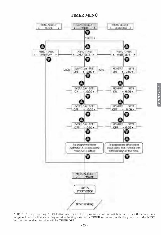
TIMERAn in-built timer allows the user to program dosing cycles as follows:• Timer Disabled: Pump works in manual mode without timer influence.• Daily Timer: The user can program up to 8 start/stop cycles per day.• WEEKLY TIMER: The user can program up to 8 start/stop cycles per week.
8.2 INPUT/OUTPUT EXTERNAL CONNECTIONS (FOR EXTERNAL ACCESSORY)As shows on paragraph 7.0 the four connectors are used for connecting the accessories.Namely the accessories are:- Level control switch;- Flow sensor;- Water meter output (Reed switch type);- Signal 4-20 mA from any device.One extra connector is used to sense the operation of the service relay (output relay).It is very important to disconnect the power from the pump when connecting the accessories. It is also veryimportant to protect the unutilized connectors with male connectors supplied witht he pump.

• 41 •
Such operation will protect the internal circuitry from unwanted shorts and/or the power surge either from theoperator or from different sources. There will be no accessible contacts after installation is completed.It is imperative that the accessories will be supplied by the factory to avoid unwanted mismatched situationsand/or furthed possible damage (wich in this this case will be no covered by the warranty).Further more cables and accessories must be idoneus and rated for the proper voltage and type of insulation.
SUMMARY OF TYPE OF CONNECTIONS1. OUTPUT SERVICE RELAY: such relay utilize the pins #1-2-3 (connecctor #1 paragraph 7.0) wich areactivated in case of alarm status.It must be noted that the operation of such relay are as follows:- when the power of the pump is not present the relay is relaxed: contact closed pin 1 and 3;- when the pump is operational -no alarm condition- the relay is energized: contact closed pin 2 and 3;- in case of alarm the relay is deenergized: contact closed pin 1 and 3; (such condition is the same of pump not
powered.
2. INPUT LEVEL SWITCH: as shown on paragraph 7.0 the pins #3-4 from position 2 are dedicated to the opera-tion of the level sensor. Such operation is activated by a float containing one magnet if the liquid is below theposition or completely absent the flow will slide down activating a reed switch.
3. INPUT FLOW SENSOR: as shown on paragraph 7.0 the pins #1-2 from position 2 are dedicated to the opera-tion of the flow sensor .
4. INPUT FROM WATER METER: to clarify for operator our pump can be connected to a water meter generatingreed switch signal proportional to a certain quantity of water passing through out. It must be clear that such sig-nal are only of ohmic nature and they do not carring any power.Connecting to the pump a different type of water meter generating any voltage will irrevocably damage thepump thus avoiding any warranty.
5. INPUT mA SIGNAL: as shown on paragraph 7.0 to the pins #1-2 from position 3 can be applied one signal 0-20 mA. Keeping in mind to connect the positive to pin #1.
6. RS 232 e RESET: the pins #1-2-3 of the connector #4 are dedicated to the updating of the internal software ofpump. Further more the pins #3 and 4 can be shorted out, for one second, generating the RESET condition of thepump.
EN
GLIS
H

• 42 •
9.0 - TROUBLE-SHOOTING COMMON TO DLX - DLXB MF SERIES
9.1 - MECHANICAL FAULTSAs the system is quite robust there are no apparent mechanical problems. Occasionally there might be a loss ofliquid from the nipple because the tube nut has loosened, or more simply the discharge tubing-has broken.Very rarely there may be losses caused by the breakage of the membrane, or by the membrane seals in whichcase they have to be replaced by disassembling the four screws of the pump head fig. 10), when re-mountingthe pump head ensure that the screws are replaced properly, along with “O” ring.After repair, the metering pump will need to be cleaned of additive residues which can damage the pump cas-ing.
❶ - THE METERING PUMP GIVES PULSES BUT THE ADDITIVE IS NOT INJECTED
a. Dismount the suction and discharge valves, clean them and replace, see position (fig. 10). Should the valvesbe swollen, check valves material against our chemical resistance compatibility chart and fit correct valves.Standard valves are Viton. Upon request Silicon, EPDM (Dutral), Nitryl and valves, ball check valve, K valvecan be supplied.
b. Check clogging of the filter.
ATTENTION: When removing the metering pump from the plant, be careful as there might be some residualadditive in the discharge hose.
9.2 - ELECTRICAL FAULTS
❶ DISPLAY OFF, NO LED LIGHT ON
a. Check power supply line (AC plug, power cord, fuse and connections). If not working please contact the near-est distributor
❷ DISPLAY ON, RED LED (POWER/STAND BY) ON, PUMP NOT OPERATIONAL
a. Check whole programming data previously inserted or push the Start/Stop button.
❸ PUMP PULSES ARE NOT CONSTANT
a. Check that supply voltage is within +/- 10% of rated voltage
❹ PUMP MEMORY NOT WORKING
a. Power up the pump for 12 hours at least to allow the internal battery to charge up (this is especially impor-tant during first start-up). If problem persist contact the nearest distributor.
❺ FLOATING SWITCH (TANK LEVEL SENSOR) NOT WORKING
a. Check that the connection between level probe and pump is securely fastened.b. If problem persists make a short connection between pin #3 and pin #4 on the second connector at the pump
body. In case the pump turns on the alarm, replace level probe. If problem persists, contact distributor.
❻ PUMP NOT WORKING WHEN WATER METER MODES 1XN, 1XN(M) AND 1/N ARE SELECTED
a. Check that the connection between the water meter cable and pump is securely fastened.b. This function can be tested by selecting the 1 x N mode (choose a value of N), removing the water meter
cable, then short-circuiting pins #3 and #4 on the pump connector for one second. If the pump pulses N timesit is necessary to check the water meter. If problem persists, contact distributor.
❼ PUMP ALARM NOT WORKING WHEN CONNECTED WITH FLOW-SENSING DEVICE
a. Check that the connection between the flow-sending device and pump is securely fastened.b. Ensure the pump is primed - the pump head should be filled with liquid.c. Start the pump again. If the alarm persist use a spring loaded on/off switch (the one with normally open con-
tact) connect to #2 pump connector (pin #1 and #2) than follow instruction in section d.d. Select the manual mode on the menu screen. Set 30 pulses/minute; subsequently in the alarm menu set 4
reference pulses of and 1 the max difference therefore press start/stop: the pump will start working in man-ual way (turned on green led and flashing red led of the pulses). For every pump pulses press the on/offswitch button to simulate the flow sensor: if the pump doesn't put itself in alarm, replace the flow sensor. Inthe case in which the pump goes in alarm simulating the flow sensor with the button to turn please contactdistributor.

• 43 •
❽ THE PUMP JUST SWITCHED ON GIVE TWO OR THREE INJECTION AND THEN STOP
Check the Remote Control Menù and the Alarm Menù for proper setting. If setting are correct, reset the pump follow-ing the procedure described in chapter 9.3.
➒ IN CASE THE ADDITIVE LEVEL IS BELOW THE LEVEL PROBE AND THE LEVEL ALARM IS STILL OFF
Check the level switch connection, short circuit poles connector (Section 7.0 pos. 2), in case the alarm is on, repla-ce the switch; if the alarm is off, contact manufacturer customer service, dealer or distributor.
9.3 RESTORATION OF DEFAULT PARAMETERSIf for any reasons the user wants to erase all the parameters and re-start the pump to the default setting, press theSTART/STOP (9) button and contemporarily press PREVIOUS (8) and NEXT (2) arrows.When START/STOP button is pressed the pump will reset to default setting.This will cancel all set parameters.
EN
GLIS
H

• 44 •
MAIN MENÙ

• 45 •
MANUAL MENU
EN
GLIS
H

• 46 •
1xN MENÙ
1xN (M) MENÙ
• 47 •
1:N MENÙ
EN
GLIS
H

• 48 •
mA MENÙ

• 49 •
P.P.M MENÙ
EN
GLIS
H

• 50 •
ALARM MENÙ
REMOTE CONROL MENÙ

• 51 •
BUZZER MENÙ
EN
GLIS
H

• 52 •
CLOCK MENÙ
• 53 •
TIMER MENÙ
NOTE 1: After pressuring NEXT button user can set the parameters of the last function which the access hashappened. At the first switching on after having entered in TIMER sub menu, with the pressure of the NEXTbutton the recalled function will be TIMER OFF.
EN
GLIS
H

• 54 •
LANGUAGE MENÙ

Via dei Ranuncoli, 53 - 00134 ROMA - ITALYHEAD OFFICE - ITALY
Phone +39 06 93 49 891 - Fax +39 06 93 43 924e-mail: - web: [email protected]
Via Ghisalba, 1320021 Ospiate di Bollate(MI) ITALYPhone +39 02 35 04 588Fax +39 02 35 05 421
ITALY (BRANCH OFFICE)ETATRON D.S.
Techniques CentreSingapore 408560Republic of SingaporePhone +65 67 43 79 59Fax +65 67 43 03 97
ASIA ETATRON D.S.(Asia-Paci�c) PTE Ltd67 Ubi Crescent, #03-05
Rua Vidal de Negreiros, 108Bairro Canindé - CEP 03033-050SÃO PAULO SPBRASILPhone/Fax +55 11 3228 5774
BRASILETATRON do Brasil
ETATRON FRANCE1 Mail Gay Lussac95000 Neuville Sur OiseTel: +33 (0)1 34 48 77 15Fax: +33 (0)1 78 76 73 95
3-rd Mytishenskaya, 16/2129626 MoscowRUSSIAPhone +7 495 787 1459Fax +7 495 787 1459
RUSSIAN FEDERATIONDOSING SYSTEMS
1642 McGaw AvenueIrvine, CA 92614USAPhone +1 949 251 8700Fax +1 949 752 7867
USA - CANADA - MEXICOETATRON AMERICA
Soborna Street, 446Rivne, 33024 Rivne RegionUKRAINEPhone +380 36 26 10 681Fax +380 36 26 22 033
UKRAINE000 ETATRON - UKRAINE Etatron GB
Lindum Business ParkStation Road North HykehamLincoln, LN6 3QX UKPhone +44 (0) 1522 85 23 97Fax +44 (0) 1522 50 03 77
UNITED KINGDOM
Avda. Letxumboro 83Pabellón 6Irún (20305) ESPAÑAPhone +34 902 09 93 21Fax +34 943 09 03 12www.etatron.es
ESPAÑA - ETATRON DOSIFICACION Y MEDICION S.L.
COD. DMU 00023ML1-A (11-2005)
A B C D