principles GB. - Celduc relais
20
celduc ® Proud to serve you All technical characteristics are subject to change without previous notice. Caractéristiques sujettes à modifications sans préavis. r e l a i s S/GEN/PRINCIPES/B/23/11/1999 page 1/ 18 F SOLID STATE RELAY (SSR) PRINCIPLES A - General page 2 B - Constitution of a solid state relay page 2 1- Input circuit page 2 2- Adaptation circuit page 3 2-1 - Zero cross control page 3 2-2 - Instantaneous control page 3 2-3 - Peak voltage control page 3 2-4 - Control for upgraded solid state relays page 3 3- Power switching component page 3 3-1 - Types et caractéristiques page 3 3-2 - Thermal page 4 3-2-1 Voltage drop at on state page 4 3-2-2 Cooling and choice of heatsink page 4 a) reminder of ohm’s law page 4 b) Modules without heatsinks page 5 c) Relays with base plate page 5 c-1 : Determination by calculation l page 5 c-2 : Using the thermal curves page 5 d) Mounting without heatsink on backplate page 6 e) Mounting several relays on the same backplate page 6 f) Using ready-to-use relays page 7 g) Precautions for mounting page 7 4- Protection circuit page 7 4-1 Protection by RC network page 7 4-2 Protection by VDR page 7 C — Other important characteristics page 8 1- Peak voltage page 8 2- Insulation page 8 3- Leakage current page 8 4- Nominal current page 8 5- Surge current page 9 6- Merging integral or I2t page 9 7- Protecting solid state relays from short-circuits of the load page 9 7-1 Protection by fuses page 10 7-2 Protection by circuit-breaker page 10 7-3 Choice of circuit-breaker page 10 D — Special relays page 11 1- Relays for direct current page 11 2-Interface modules page 12 3- Upgraded relays page 12 4- Special and power electronic relays page 12 E — Reliability and conformity page 12 1- Technology (DCB) page 12 2- Tests page 12 3- Lifetime and MTBF page 13 4- Standards and "CE" marking page 14 5- Specific point on EMC page 15 5-1 Main EMC standards adapted to solid state relays page 16 5-1-1 Immunity page 16 a) EN61000-4-2 and EN61000-4-3 page 17 b) EN61000-4-4 and EN61000-4-5 page 18 5-1-2 Emission page 18
-
Upload
khangminh22 -
Category
Documents
-
view
6 -
download
0
Transcript of principles GB. - Celduc relais

celduc®PPPPrrrroooouuuudddd ttttoooo sssseeeerrrrvvvveeee yyyyoooouuuu
All technical characteristics are subject to change without previous notice.Caractéristiques sujettes à modifications sans préavis. r e l a i s
S/GEN/PRINCIPES/B/23/11/1999
page 1/ 18 F
SSOOLLIIDD SSTTAATTEE RREELLAAYY ((SSSSRR))PP RR II NN CC II PP LL EE SS
A - General page 2B - Constitution of a solid state relay page 2 1- Input circuit page 2 2- Adaptation circuit page 3 2-1 - Zero cross control page 3 2-2 - Instantaneous control page 3 2-3 - Peak voltage control page 3 2-4 - Control for upgraded solid state relays page 3 3- Power switching component page 3 3-1 - Types et caractéristiques page 3 3-2 - Thermal page 4 3-2-1 Voltage drop at on state page 4 3-2-2 Cooling and choice of heatsink page 4 a) reminder of ohm’s law page 4 b) Modules without heatsinks page 5 c) Relays with base plate page 5 c-1 : Determination by calculation l page 5 c-2 : Using the thermal curves page 5 d) Mounting without heatsink on backplate page 6 e) Mounting several relays on the same backplate page 6
f) Using ready-to-use relays page 7
g) Precautions for mounting page 7
4- Protection circuit page 7
4-1 Protection by RC network page 7
4-2 Protection by VDR page 7C — Other important characteristics page 8
1- Peak voltage page 8
2- Insulation page 8
3- Leakage current page 8
4- Nominal current page 8
5- Surge current page 9
6- Merging integral or I2t page 9
7- Protecting solid state relays from short-circuits of the load page 9
7-1 Protection by fuses page 10
7-2 Protection by circuit-breaker page 10
7-3 Choice of circuit-breaker page 10
D — Special relays page 11
1- Relays for direct current page 11
2-Interface modules page 12
3- Upgraded relays page 12
4- Special and power electronic relays page 12
E — Reliability and conformity page 12
1- Technology (DCB) page 12
2- Tests page 12
3- Lifetime and MTBF page 13
4- Standards and "CE" marking page 14
5- Specific point on EMC page 15
5-1 Main EMC standards adapted to solid state relays page 16
5-1-1 Immunity page 16
a) EN61000-4-2 and EN61000-4-3 page 17
b) EN61000-4-4 and EN61000-4-5 page 18
5-1-2 Emission page 18

celduc
r e l a i sRue Ampère B.P. 4 42290 SORBIERS - FRANCE E-Mail : [email protected] +33 (0) 4 77 53 85 51 Service Commercial France Tél. : +33 (0) 4 77 53 90 20 Sales Dept.For Europe Tel. : +33 (0) 4 77 53 90 21 Sales Dept. Asia : Tél. +33 (0) 4 77 53 90 19
www.celduc.com
S/GEN/PRINCIPES/B/23/11/1999
page 2/18 F
A-GENERAL
Solid state relays are switching devices made from electronic components. The term "Relay" is used as in electromechanical relays which are
separated galvanically from the control circuit and switched circuit and "solid state" confirming that there are no moving parts.
Thanks to electronics, these relays have three essential characteristics :
- Amplification : very low control power directly adapted in terms of voltage and current with the logic outputs of electronic systems, giving rise
to an extremely simplified control circuit with no relay coils that always tend to generate "interference".
- Rapidity and the possibility of choosing the switching moment : zero cross tripping on resistive loads (or another mode of control suited to the
load) and zero-current switching preventing sharp instantaneous variations of interference-generating current. This is an essential factor with the
new European directives pertaining to electromagnetic compatibility (EMC) both in terms of conducted and radiated disturbances.
- No moving parts giving rise to a practically unlimited operating life, no arcs (explosion-proof), fully moulded
therefore ideal for polluted atmospheres (dust, gas, etc), noiseless, resistant to shocks and vibrations.
Alternatively, electronic relays must be suitably cooled since the voltages and currents must not exceed the values specified
and the output in blocked state has a minimum leakage current.
celduc manufactures an extensive range of solid state power relays up to 125 Amperes, single or three phase, input/output
interface modules and a range of upgraded solid state relays designed for improved control of certain loads when it comes to power,
speed, starting or rotation direction control.
B- CONSTITUTION DES RELAIS STATIQUES .
A solid state relay is made up of 4 major parts ( figure 1)
1 / INPUT AND INSULATION CIRCUIT :
This circuit provides the galvanic insulation between the input circuit and
the rest of the mounting. It is made up of an optical control called an opto-
coupler (figure 2).
The input current, limited by the resistor R , proportional to the
control voltage, is applied to a light-emitting diode (LED) . The light acts
on a photosensitive component which transmits information to the
output.As the operating current is usually 2 to 3mA , the power required for
the control is therefore very low. As the LED takes currents from 2 to
30mA , the control voltage can generally be between 4V and 30VDC. A
diode serial or anti-parallel
mounted on the LED protects it from a reversed polarity input connection.
For an alternating voltage control, a rectifier bridge, a filter and a resistor
are fitted (figure 3). So, the control of the LED of the photocoupler is
unchanged.
The tolerance on the current similarly allows for deviations from 17 to
80VAC or 90 to 240VAC. A certain amount of celduc relays also have a
built-in LED displaying the state of the input.
The optocouplers used in the celduc relays comply with the VDE0805
standard have an input/output insulation > 3750VRMS , a very low
input/output capacity with a very high immunity level : >10 000V/ s .
R
RFig. 2
Input circuit
Fig. 3Input circuit for
alternating control
Photosensitive component.
Input circuit
Adaptation circuit
Power switching component
Protective circuit
Insulation
Entrée
Control voltage
fig. 1 . Constitution of a solid state relay .
Network
load
Phase
Neutral
load

celduc
r e l a i sRue Ampère B.P. 4 42290 SORBIERS - FRANCE E-Mail : [email protected] +33 (0) 4 77 53 85 51 Service Commercial France Tél. : +33 (0) 4 77 53 90 20 Sales Dept.For Europe Tel. : +33 (0) 4 77 53 90 21 Sales Dept. Asia : Tél. +33 (0) 4 77 53 90 19
www.celduc.com
S/GEN/PRINCIPES/B/23/11/1999
page 3/18 F
2 / ADAPTATION CIRCUIT :This circuit receives the control signal and transmits it to the switching component.
According to the type of relay, the making moment can take place at different
levels of mains voltage. There are therefore different categories of relays.
2 - 1 -/Zero cross relays:The power switching only takes place at the start of the half-cycle following
the application of the control. Indeed, the switching of the power component
is only permitted in the area around the zero crossing .
This area is still called the "zero crossing window"or sometimes the "zero
crossing level". celduc solid state relays have a very low zero crossing level
(usually <10 Volts ). This control prevents sharp variations in current on all the
RESISTIVE loads ( Fig. 4 ) : lamps,
heating elements,...... and prolongs the lifetime of these components.
This control is also suited to control capacitive loads with a few extra precautions
(special application note available on request)
celduc solid state relays can also be used on inductive loads, even
though the zero cross control is not optimised.
2 - 2 /Instantaneous control or random relays:The power switching takes place from the application of the control voltage
(100 s) . This control is most suited to all the CONDUCTIVE type controls
due to the dephasing between the current and voltage. ( Fig. 5)
2 - 3 /Voltage peak control or peak starting relays :(SCP)The power switching only takes place at the voltage peak of the half-cycle following
the application of the control. This control is particularly suited to the control of
TRANSFORMER type inductive saturating loads.
This prevents the transformer from being saturated and also significant
magnetising current peaks ( Fig. 6 ). Special application note on request.
2 - 4 /Upgraded solid state relays :Models incorporating more sophisticated or specific interfacing functions :
* soft start motor control,
* light or speed control (phase angle controllers : fig 7)
* heating power control (standard "syncopated" full wave pulse controllers)
: fig 8
* suitable for the switching of loads supplied with DIRECT CURRENT
* suitable for INTERFACING electronic circuits with power
circuits, both INPUT and OUTPUT.
* using the celduc " SOFTLIFE" technology combining the assets of
solid state relays : reliability, lifetime, noiseless with those of
electromechanical relays : compact, no heating.
load voltage
0t
Fig. 6transformer load peak
relay
load voltage
t
current load
relay control voltage
0t
Zero-crossing
windowFig.4resistive load
zero cross
relay
load voltage
0 t
load voltage
0t
Fig. 5induction load random relay
load current
0 t
Fig. 7Phase angle
controller
relay
Fig. 8Full wave
pulse controller
relay
0-10V or 4-20mA analog input relay
relais à entrée tout ou rien
Fig. 9 Back-to-back thyristors Fig. 10 Triac
3 — POWER SWITCHING COMPONENT.
3-1 TYPES AND CHARACTERISTICSThe switching components of solid state relays for alternating networks are thyristors or triacs. Thyristors are control gate diodes.
They are conductors in one direction only. Two thyristors should be mounted back to back to transmit the 2 half-cycles of the mains
(figure 9). Triacs are semiconductors controlled by the gate capable of conduction in both directions. One single triac can switch
the 2 half-cycles of an alternating network (figure 10).

RELAY VOLTAGE
celduc
r e l a i sRue Ampère B.P. 4 42290 SORBIERS - FRANCE E-Mail : [email protected] +33 (0) 4 77 53 85 51 Service Commercial France Tél. : +33 (0) 4 77 53 90 20 Sales Dept.For Europe Tel. : +33 (0) 4 77 53 90 21 Sales Dept. Asia : Tél. +33 (0) 4 77 53 90 19
www.celduc.com
S/GEN/PRINCIPES/B/23/11/1999
page 4/18 F
There are 2 other ways to make these power components conduct but do however hinder
the use and are to be warned against :
- Arcing by dv/dt (static) : With the component in the blocked state (not controlled), if a
sudden variation of voltage is applied across its terminals, the Anode / Gate parasite
capacity generates a gate current (i = Cdv/dt) likely to lead to the conduction of the
semiconductor during a mains half-cycle.
-Arcing by PEAK VOLTAGE. If a significant voltage higher than the maximum
allowable voltage (MAX PEAK VOLTAGE) is applied, there is an avalanche effect on the
semiconductor and it becomes conductive. This arcing can be destructive if it is followed
by a significant current.
Standard triacs also have another disadvantage : when a triac is conductive, at the time
where the current is cancelled, a voltage must not be reapplied too quickly across its
terminals as this may stop it from blocking.
When switching OFF on an inductive load (whatever the type of relay), the mains voltage
is reapplied quickly when the current is stopped due to the dephasing between the current
and voltage. The resistance of a triac on this reapplication of voltage called dv/dt on the
switching ((dv/dt)c) greatly depends on the slope of the current at the time of blocking
((di/dt)c). (fig. 11). This is why triacs are only used for small currents.
These various components have a function in common :
-They only conduct provided the suitable current is applied to the control electrode (gate). Once the
conduction is made, it is maintained, even if there is no gate current, up to ZERO, or up to at least a current
value less than its HOLDING CURRENT (usually 50mA). In a solid state relay this holding current is sometimes indicated. It is only useful if
the relay is pulse controlled and is not to be mixed up with the MINIMUM WORKING CURRENT of a solid state relay. Indeed, when the
control is applied permanently, if the current is less than the holding current, it is the pilot control circuit of the power component which provides
the conduction of the current of the load.
On the other hand, the majority of the power components used by celduc have a static dv/dt > 500v/ s (compared to the 200v/ s
standard). For peak voltage resistance celduc has generalised 600V for the 110 and 230VAC relays and 1200V for the 400VAC relays
and offers 1600V relays. For additional protection see the protection ⁄. For the immunity of products see the EMC ⁄.
0t
Fig. 11switching OFF
inductive load
relay voltage
tload current
0
OFF control
(di/dt)c
(dv/dt)c
3-2-1 VOLTAGE DROP AT ON STATE
At on state, solid state relays have residual voltage. This drop in voltage at
the on state is in phase with the current and takes on the form shown in figure 12 :
Va : ARCING VOLTAGE or minimum voltage required to send a correct control to the
power component (appears on each zero crossing of the current). This voltage has been
reduced by a maximum on the celduc solid state relays (usually 7 to 8V instead of 20V :
which reduces the deformations of the mains sine wave and the level of conducted emission
(EMC) . This voltage (not to be confused with the zero cross voltage which only takes places
on the half-cycle after the application of the control (⁄3-2)) calls for a minimum working
voltage of the solid state relays : usually 12 VAC .
Vt : Threshold voltage due to the junction of the semiconductor : usually 0.8 to 1 V .
(This voltage drops with the temperature : approx. 2mV/¡C).
rt : resistance at the on state of the semiconductor and connections :
usually 5 to 30µΩ according to the rating of the relay.
0t
Fig.12voltage drop at on state
(A precise measurement can only be made
with an oscilloscope).
0 t
LOAD CURRENT
Va
rt x Im
Vt
3-2 THERMAL
3-2-2 COOLING AND CHOICE OF HEATSINK :The switching component must be suitably cooled so that the junction temperature does not exceed the values specified :
usually 110 or 125¡C .
a) REMINDER OF OHM'S LAW : ∆T = Rth x PD whereAT = Difference of temperature between the junction and the ambient air
Rth = Junction/ambient air thermal resistance. It can be made up of several serial mounted thermal resistors ( Rth ).
PD = Power dissipated by the relay. Expressed in Watts (joules per second), corresponds to the thermal current or
the calories to be discharged from the relay, mainly depends on the current crossing the relay.
In order to overcome these disadvantages, celduc uses more efficient components as opposed to standard triacs :
-LOW POWER: Use of new generation triacs with high switching characteristics : SNUBBERLESS TRIACS
or HIGH LEVEL SWITCHING.
-MEDIUM POWER : Use of ALTERNISTORS which are practically 2 thyristors diffused over the same silicon chip.
-HIGH POWER: Use of BACK-TO-BACK THYRISTORS.
celduc relays have a high switching performance.

celduc
r e l a i sRue Ampère B.P. 4 42290 SORBIERS - FRANCE E-Mail : [email protected] +33 (0) 4 77 53 85 51 Service Commercial France Tél. : +33 (0) 4 77 53 90 20 Sales Dept.For Europe Tel. : +33 (0) 4 77 53 90 21 Sales Dept. Asia : Tél. +33 (0) 4 77 53 90 19
www.celduc.com
S/GEN/PRINCIPES/B/23/11/1999
page 5/18 F
b) MODULES (without external heatsink) : It is the case, the resin, the internal heatsink which act as a dissipator to
discharge the calories .
In an SK type case, the junction/ambient air thermal resistance is in the region of 20 to 25 ¡/W
=> max PD = (Max. junction temperature — Ambient temperature)/20 max PD = (110 - 30 ) /20 = 4 Watts hence max rms I at 30¡C = 4
Amperes. ( see 5 A). For the modules, a curve specifies the maximum current according to the ambient temperature.
c) RELAYS WITH BASE PLATE (MACROMODULES) MOUNTED ON HEATSINK : The heatsink can be determined either by calculation or directly from the curves provided by celduc.
c-1) Determination by calculation :To simplify things and presuming that the relay is mounted correctly i.e.
mounting with thermal conductive grease (silicon grease or thermal interface
proposed by celduc) , that the relay/heatsink contact as well as the tightening
of the fastening screws are correct, the thermal mounting resistance can be
ignored (usually 0.1¡/w).
In general, the known elements are the power to be dissipated ( PD) :
Pd = 0.9xVtxI + rtxIxI (determined according to the RMS current crossing
the relay) and the ambient temperature (Tamb) .The max junction temperature
(Tjmax) and junction / case thermal resistance values (Rth j/b or Rthj/c) are
given in the celduc specifications.
Rth < T / PD
∆T
j/a
JUNCTION
HEATSINK
THERMAL GREASE
AMBIENT AIR
Rth j/b
Rth
HE
AT
SINK
fig.10 : HEATSINK
On the other hand, the temperature of the relay, therefore, the heatsink must be limited to max Tcase (90 or 100¡C) specified in the specifications Rth heatsink < (max Tcase —ambientT) / PD
Example : RMS I = 20A ------> PD = 24Watts (for a relay with Vt = 1V and rt = 15 µΩ ) Max ambient T = 30¡C
Si Rth j/c =1,1°/W, Tj max = 125°C , T case max =90°C ∑Rth < (125-30)/24 =3,9°/w -------->Rth radiateur <3,9-1,1 =2,8°/W Rth radiateur < (90-30)/24 = 2,5°/W Le choix se portera sur un radiateur de Rth <2,5°/W --------> standard celduc 2°/W c-2) using the curves given by celduc (fig 13):
1
2
2
1
max T case(°C)
125
0
5
0 5 10 15 20 25 30 35 40
10
15
20
25
30
35
40
45
50
55
60
0 10 20 30 40 50 60 70 80 90 100 110 120
0,4°C/W
0,7°C/W
0,9°C/W
1°C/W1,2°C/W1,5°C/W
2°C/W
0°C/W
85
75
65
90°C
Pdmoy (W)
I (A)
ambT (°C)
WITHOUT HEATSINK
4°C/W
fig 13: THERMAL CURVES
P2P1
Pd=f(I
)
P3
P4
duty cycle = 0,5

celduc
r e l a i sRue Ampère B.P. 4 42290 SORBIERS - FRANCE E-Mail : [email protected] +33 (0) 4 77 53 85 51 Service Commercial France Tél. : +33 (0) 4 77 53 90 20 Sales Dept.For Europe Tel. : +33 (0) 4 77 53 90 21 Sales Dept. Asia : Tél. +33 (0) 4 77 53 90 19
www.celduc.com
S/GEN/PRINCIPES/B/23/11/1999
page 6/18 F
The type of heatsink to be used can be determined directly according to the switched currrent and the ambient temperature.
previous example with RMS I = 20Amperes and max. ambient temperature = 30¡C
Operating mode /fig 13:
- identify the current to be switched on the abscissa of the left hand curve.
-plot a vertical line from this point up to the curve Pd=f(I) (the power to be dissipated can be read on the ordinate).
-from the point obtained ( P1), a horizontal line is plotted to the right hand curve.
-identify the ambient temperature on the abscissa of the right hand curve.
-plot a vertical line from this point until you meet the horizontal line previously plotted. This point (P2) determines the type
of heatsink to the used.
- choose the heatsink corresponding to the curve located above this point. In the example 2¡/W
You can see that with a heatsink of 2¡/W and 20Amperes, the ambient temperature should not exceed 43¡C (P3).
with a heatsink of 2¡/W and an ambient temperature of 30¡C the maximum current could reach 25 Amperes (P4).
It is to be pointed out that this determination is performed when permanent operation is involved. For intermittent uses : duty cycle < 1 , you
can take the mean power dissipated or use the "Power dissipated" curve with the suitable duty cycle ( in the above example : duty cycle =
0.5). This is only true if the duty cycle remains greatly inferior to the thermal constant of the heatsink. You must watch out for the
preheating time of machines which may correspond to permanent operation.
The ordinate of the right hand curve gives the maximum case temperature of the relay ( max Tcase) according to the power dissipated.
Example : for mean Pd = 40watts --> Tcase must not exceed 85¡C
d) Mounting without heatsink or mounting on backplate of cabinetA curve without heatsink is given for the SC or SG type solid state relays.
When mounted on the backplate of a cabinet, the relay/plate contact must be correct.
An aluminium backplate of the correct thickness of 150mm x 150mm corresponds to approximately 4¡/W
An aluminium backplate of the correct thickness of 300mm x 300mm corresponds to approximately 2¡/W
In all cases, you are advised to perform a test and measure the heating. A steel plate will have greater thermal
resistance,........
e) Mounting several relays on one heatsink (fig 14) Thermal constant notion.
A lot of solid state relays are mounted on the backplates of cabinets on one heatsink.
This solution has the advantage of optimising the heatsink which has a good
thermal capacity at the time of heating of the machine (preheating) when all the
solid state relays are called upon permanently. The value of the thermal constant of
the celduc heatsinks is specified. This Cth value ( figure 15 ) corresponds to the time of the
rise in temperature of the heatsink : Cth = 67% the time that the heatsink takes to stabilise (Ts
value given in still air)
In control mode this mounting gives rise to an optimum distribution of the calories over the
whole heatsink.
32A
15 minutes duty cycle = 0,5
heatsink temperature
thyristor temperature
Cth
Ts
67% Ts
To determine the heatsink, add all the powers dissipated for each relay. Redo the thermal resistance
calculation required : Rth = T/ Pd . The best solution is to carry out a thermal test in the worst operating conditions and to check that the temperature of the heatsink does not exceed the maximum specified.
fig 14
fig 15
celduc
r e l a i sRue Ampère B.P. 4 42290 SORBIERS - FRANCE E-Mail : [email protected] +33 (0) 4 77 53 85 51 Service Commercial France Tél. : +33 (0) 4 77 53 90 20 Sales Dept.For Europe Tel. : +33 (0) 4 77 53 90 21 Sales Dept. Asia : Tél. +33 (0) 4 77 53 90 19
www.celduc.com
S/GEN/PRINCIPES/B/23/11/1999
page 7/18 F
g) Precautions and tips:- The values of the power dissipated according to the current crossing the relay are
given for permanent operation on the celduc curves. In the case of
intermittent operation, some curves give the power rating with a
duty cycle = ton/toff <1 . These values are only valid for short periods,
less than the thermal time constants of the heatsinks.
- The thermal resistance of a heatsink is defined in determined conditions
of use : vertical mounting ( fig 17), ........ In the case of use in a severer
atmosphere (cabinet with no aeration), include a safety coefficient ( 20 to
30%).
- The Thermal resistance values of the celduc heatsinks are given
in natural convection, in the vertical position and in an enclosed housing.
Forced ventilation around the SSR and its heatsink (fan) can allow for the size
to be reduced significantly :
The thermal resistance of a heatsink is divided by 2 with an air speed of 1.5 m/sand by 4 with an air speed of 5m/s.
The use of an oversized heatsink boosts the reliability and lifetime ofsolid state relays.
f - : Using ready-to-use relays (fig 16)
celduc proposes a range of ready-to-use relays which
can be directly DIN rail mounted or screwed on.
The values of the switching current are directly given
in compliance with the European standards, i.e.
corresponding to limited temperature rises.
- max 50¡C for heatsink
- max 50¡C for cover fig 16
vertical mounting
Air 20mm minimum
20mm minimum
thermal
grease or
interface
fig 17
4-1 ) PROTECTION BY RC NETWORK OR SNUBBERLimits sudden variations of voltage : dv/dt and (dv/dt)c (fig 18)
These can arise :
- on switching on.
-on switching inductive loads.
-on mains interference.
The celduc relays have been improved in terms of resistance to these factors enabling the RC network to be reduced
substantially or practically eliminated.
--> celduc guarantees its relays for immunity in keeping with the standard EN61000-4-4 which corresponds to
quick transients (see EMC ⁄ ). The majority of relays are guaranteed with resistances without arcs at 2kVolts (even 4 kVolts) whereas the test
is performed with rising times to within a nano second.
dv/dt 4 - PROTECTION CIRCUIT :
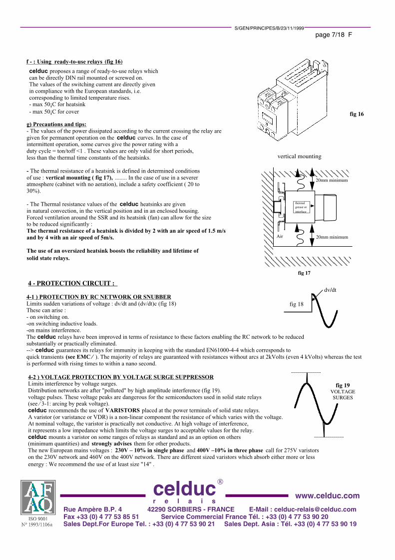
4-2 ) VOLTAGE PROTECTION BY VOLTAGE SURGE SUPPRESSORLimits interference by voltage surges.
Distribution networks are after "polluted" by high amplitude interference (fig 19).
voltage pulses. These voltage peaks are dangerous for the semiconductors used in solid state relays
(see ⁄ 3-1: arcing by peak voltage).
celduc recommends the use of VARISTORS placed at the power terminals of solid state relays.
A varistor (or varistance or VDR) is a non-linear component the resistance of which varies with the voltage.
At nominal voltage, the varistor is practically not conductive. At high voltage of interference,
it represents a low impedance which limits the voltage surges to acceptable values for the relay.
celduc mounts a varistor on some ranges of relays as standard and as an option on others
(minimum quantities) and strongly advises them for other products.
The new European mains voltages : 230V – 10% in single phase and 400V –10% in three phase call for 275V varistors
on the 230V network and 460V on the 400V network. There are different sized varistors which absorb either more or less
energy : We recommend the use of at least size "14" .
fig 19VOLTAGE SURGES
fig 18

celduc
r e l a i sRue Ampère B.P. 4 42290 SORBIERS - FRANCE E-Mail : [email protected] +33 (0) 4 77 53 85 51 Service Commercial France Tél. : +33 (0) 4 77 53 90 20 Sales Dept.For Europe Tel. : +33 (0) 4 77 53 90 21 Sales Dept. Asia : Tél. +33 (0) 4 77 53 90 19
www.celduc.com
S/GEN/PRINCIPES/B/23/11/1999
page 8/18 F
1 ) PEAK VOLTAGE :
--> In power electronics, the general rule is to have semiconductors with a voltage withstanding double that of the peak
voltage of the network. This is why celduc recommends 600Vpeak relays on 12-280VAC networks ; 1200Vpeak relays on
24-520VAC networks and 1600V for networks up to 600VAC.
It is to be pointed out that some loads : capacitive, motors, etc., may generate voltage surges. In this case the peak voltage of the relay must account for these surges. celduc proposes relays of 600V, 1200V and 1600volts as standard. See solid state relay selection guide .
2 ) INSULATION :--> All the celduc relays have an insulation voltage between input and output of 4000VAC .
The output/heatsink insulation is from 2500VAC to 4000AVC depending on the models, in compliance with the
European and international standards.
The standard IEC947-1 (or EN60947) specifies the voltage assigned to shock resistance = Uimp . The majority of celduc products are specified
at Uimp=4000V and are defined for a degree of pollution 2 as per IEC664-1.
C - OTHER IMPORTANT CHARACTERISTICS :
AS A GENERAL RULE :* The celduc solid state relays suitable for resistive loads : SC9, SGT9 series have a high immunity level as per EN61000-4-
4 ==> an RC is not necessary. It is strongly advised to use a voltage surge suppressor.
* The celduc solid state relays suitable for all loads : SC8, SGT8 series and the celduc random solid state relays : SC7,
SGT7 series have a very high immunity level as per EN61000-4-4 and are fitted with an internal RC network. It is
strongly advised to use a voltage surge suppressor which is often integral in the SV products.
4 ) NOMINAL CURRENTThe current which flows in the relay must not exceed the maximum current of the power component during
permanent operation. This current is directly proportional to the size of the silicon chip mounted in the solid state relay
and depends on the cooling.
celduc usually uses well-sized chips with respect to the maximum current stated. To find out the actual size
of the chips used by relay manufacturers, it is interesting to compare the surge values ( Itsm and I2t ) which arethe values directly proporiontal to the size of the semiconductors (see next ⁄) .
The celduc range is 4A- 12A-25A-50A-75A-95A-125A. However, this maximum current may only be reached provided
the temperature of the power component does not exceed the maximum allowable value (usually 125¡C - see ⁄ : thermal).
IN THE CHOICE OF CURRENTS/TYPE OF LOADS, REFER TO THE APPLICATIONS PART where thecategories of use are defined : AC-51 ; AC-53;..............
THERMAL FATIGUE phenomenon : Electronic power components which withstand many hot/cold thermal cycles,
(which can be the case for solid state relays with on/off operation) undergo a THERMAL FATIGUE phenomenon
likely to affect the lifetime of the component (see LIFETIME ⁄).
=> AS A GENERAL RULE, SOLID STATE RELAYS SHOULD ALWAYS BE OVERSIZED.IT IS ADVISED TO DULY COOL SOLID STATE RELAYS.
3 LEAKAGE CURRENT
A solid state relay in the blocked state does not have an infinite impedance across its terminals. A low residual current
circulates in the load called the leakage current.
This is due to :
-the leakage current of the switching component. This exponentially varies with the junction temperature. It stays very low
if the junction temperature remains reasonable.
-the internal circuits acting as an interface and pilot controlling the power. The celduc new generation relays have seen
this current go from 2.5mA to less than 0.2mA.
-the RC protection networks : The improvement of the characteristics of the celduc relays means that this RC can be
minimised. This gives rise to a maximum reduction in this current leakage due to the RC and which depends on the mains
voltage and the frequency of the network. Ic = 6.28 x U x C x F .
This leakage circuit may be harmful in pilot controlling very low loads (small solenoid valves, etc) as this current may
suffice to maintain the load supplied.
As opposed to a lot of solid state relays, the celduc solid state relays have a reduced leakage current and can operate
without problem on very small loads.
Given the existing leakage current in a solid state relay, the terminals must be considered as being permanently live.

celduc
r e l a i sRue Ampère B.P. 4 42290 SORBIERS - FRANCE E-Mail : [email protected] +33 (0) 4 77 53 85 51 Service Commercial France Tél. : +33 (0) 4 77 53 90 20 Sales Dept.For Europe Tel. : +33 (0) 4 77 53 90 21 Sales Dept. Asia : Tél. +33 (0) 4 77 53 90 19
www.celduc.com
S/GEN/PRINCIPES/B/23/11/1999
page 9/18 F
5) SURGE CURRENT : ITsm (maximum surge)The semiconductor components used can accept brief surges. This peak current ITsm : ACCIDENTAL NON REPETITIVE
SURGE CURRENT AT ON-STATE is given for a mains half-cycle for triac type output relays, i.e. for a duration of 10ms in 50hertzs and
a mains cycle for thyristor type output relays, i.e. for a duration of 20ms in 50hertzs . This peak
current is in general 10 times the nominal current.
celduc gives the characteristics of the value Itsm =f(t) with 2 different curves ( fig 21):
1 : Itsm value without voltage reapplied : this curve corresponds to the values not to be exceeded when a short-circuit
occurs without the risk of destroying the semiconductor. The temperature of the silicon rises above 200¡C and the relay
loses its switching capacity. It is the protection circuit (fuse, circuit-breaker) which ensures the switching. This constraint is
not repetitive, i.e. limited in the number of times in the life of the product (<100 times)
2: surge value with voltage reapplied : this curve corresponds to the value not to be exceeded to ensure the relay keeps
its switching capacity. These curves are generally given for an initial junction temperature of 70¡C. The current surge
then gives rise to an instantaneous rise in temperature of the chip limited to the acceptable value for the semiconductor
(generally 125 or 150¡C).
This constraint can be repetitive. For inrush currents on starting :
- INCANDESCENT LAMPS (8 to 10 IN)
- CAPACITIVE LOADS
- MOTORS (4 to 8 IN)
- THERMAL HEATING ELEMENTS (1.4 In).
- TRANSFORMERS (up to 100In)
The repetitive curve Itsm checking the influence on the life time (see LIFETIME ⁄) must be used.
SURGE CURRENT Itsm (A peak) = f(t) : model with Itsm =550A
1 1010,10,010
200
400
600
0
t (s)
Itsm
(A
peak
)
Itsm (Apeak) repetitive=f(t) with voltage reapplied . Initial Tj =70°C
Itsm (Apeak) non repetitive =f(t) without voltage reapplied
fig 21
6) I2t or MELTING INTEGRAL :Used for very brief surges (<10ms) . This value corresponds to the constraint current value not to be exceeded for a
brief time so as not to destroy the power semiconductor (melting). This short time surge occurs during a short-circuit
of the load. This value corresponds to the non repetitive Itsm for 10ms .
Example : relay with I2t of 5000 A2s ----> Imax = 1000A for 10ms
t10mS
i Icc : presumed short-circuit current
Waveform obtained
behind the protection device
t0 tp tt
Fig 22
i2 dt qui est la somme de l'I2t de préarc et de et de l'I2t d'arc.t0
tt
t0
tt
t0
tt
7 ) PROTECTING SOLID STATE RELAYS FROM SHORT-CIRCUITS OF THE LOAD :During a short-circuit, the line must be protected according to the standards in force ( NFC15100 & CEI 364 ) and
therefore have a device capable of stopping the current within a reduced period of time thereby protecting
persons and equipment.
This cut-off device must be all the more rapid if it is associated to a conventional thyristor or triact type solid
state relay as these components can only withstand a limited peak current.
During a short-circuit on the line, the waveform obtained
(fig 22) depends on the presumed short-circuit current of the line
(Icc inrush current and reached if there is no protection device).
The rapidity of the protection device is characterised by the quantity
i2 dt which is the sum of of the pre-arc I2t and and the arc I2t.
This I2t value called thermal constraint, is used to
verify that the components of the circuit are duly
protected. This I2t characteristics is only valid
if the duration of the surge is of a short duration (<10ms) .
Beyond this the RMS value of the current must be considered.


celduc
r e l a i sRue Ampère B.P. 4 42290 SORBIERS - FRANCE E-Mail : [email protected] +33 (0) 4 77 53 85 51 Service Commercial France Tél. : +33 (0) 4 77 53 90 20 Sales Dept.For Europe Tel. : +33 (0) 4 77 53 90 21 Sales Dept. Asia : Tél. +33 (0) 4 77 53 90 19
www.celduc.com
S/GEN/PRINCIPES/B/23/11/1999
page 10/18 F
The I2t values of the celduc relays are the most efficient on the market with :
6-6) PROTECTION BY FUSES :
celduc recommends fuses adapted to the solid state relays for each type of load,:
- resistive load : use of FERRAZ GRB or GRC fuses
- on motor : use of standard "am" fuses with adaptation of the rating of the relay.
As a general rule, a correct safety margin of fuse I2t value would be <1/2 I2t relay.
An important factor must be taken into account : the thermal fatigue of the fuse. This is why all the
associations proposed by celduc have been tested in the FERRAZ laboratory.
6-7) PROTECTION BY CIRCUIT-BREAKERS :
celduc is currently working on self-protected solid state relays, however with the current technology self protection is put to the detriment
of the drop in voltage at on-state, therefore a bigger heatsink and added costs which remain high.
--> THE SOLUTION : SOLID STATE RELAY ASSOCIED TO A HIGH-SPEED CIRCUIT-BREAKER :
Mechanical circuit-breakers have made a great deal of progress. Very compact modular type circuit-breakers can now be found with thermal
and magnetic tripping meaning they are capable of breaking on a surge but also on a short-circuit. Their breaking capacity is more and more
efficient and reaches 15 to 25 kA in Icu current (ultimate current for which it is preferable to change them) and 10 to 20 kA in Ics current
(Operating switching current).
The magnetic tripping depends on the type of circuit-breaker.
The new high speed circuit-breakers of the "Z curve" type trip at a current corresponding to 2 to 3 In . These circuit-breakers (ABB,
MERLIN GERIN, KLOCKNER & MOELLER, ...) are in fact "short-circuit current limiters" . They are designed to limit the breaking time
and the value of the short-circuit current in order to simultaneously reduce the two factors of the on-state thermal stress (I2t on-state) .
The short-circuit current limitation value and the breaking time are of prime importance in protecting downstream circuits against the damage
incurred by short-circuits of the loa
6-8) CHOICE OF CIRCUIT-BREAKER ASSOCIATED TO SOLID STATE RELAY :
In order to determine the circuit-breaker, you must know the presumed short-circuit current (called Icc or Ip), calculated at the point where it
is installed. Fitters usually know this presumed short-circuit current at a given point of the installation, however, you
can ask celduc for the specific application note. The circuit-breaker must have a breaking capacity at least equal to Icc at the point where it
is installed in compliance with the NF C standard 15-100/434-2-1 (CEI364) .
It is the residual short-circuit current which must be taken into account to determine the degree of coordination
and selectivity.
The value of the residual short-circuit currrent and its breaking time depend on this residual short-circuit
current Icc and the type of circuit-breaker.
I2t (A2s) (<10ms)
RELAY RATING 12A 25A 40A 75A
72 312 610 5000
celduc RANGE
95A
11000
125A
20000
45/50A
1500

celduc
r e l a i sRue Ampère B.P. 4 42290 SORBIERS - FRANCE E-Mail : [email protected] +33 (0) 4 77 53 85 51 Service Commercial France Tél. : +33 (0) 4 77 53 90 20 Sales Dept.For Europe Tel. : +33 (0) 4 77 53 90 21 Sales Dept. Asia : Tél. +33 (0) 4 77 53 90 19
www.celduc.com
S/GEN/PRINCIPES/B/23/11/1999
page 11/18 F
Solid state relays are generally fitted after a series of protection and isolating devices and the cross sections of the wires are already reduced
which limits the short-circuit current to values under 5000 Amperes. Given these conditions, the I2t values obtained using "Z curve" high-
speed circuit-breakers in the event of short-circuits of the load can be accepted by the celduc high I2t solid state relays. To verify the level
of protection, just refer to the manufacturers’ curves which give :
o The tripping curves ----> to check the surge protection (thermal)
example : A 16A circuit-breaker will trip with a surge of 30A in a maximum of 20 seconds.
oThe dynamic stress curve ----> to see the limiter effect of these circuit-breakers.
example : RMS Icc = 4000A ----> max ID on-state =2400 Amperes for a 16 A circuit-breaker.
oThe thermal stress curve I2t ----> to determine the max I2t accepted by the circuit-breaker and that goes
through the solid state relay on a short-circuit according to the Icc of the line at the point of installation .
example : Icc = 2000A circuit-breaker rating = 16 A I2t max = 3200A2s
Icc = 4000A circuit-breaker rating = 25 A I2t max = 10000A2s
These values are the maximum given by the manufacturer. It is, nonetheless, to be pointed out that when using
zero cross solid state relays associated with circuit-breakers, controlling the zero cross relay limits the thermal
stress.
celduc has developed high I2t relays in the same standard cases for the use of these circuit-breakers :
Relay 45/50A : I2t >1500A2s (typ >2000A2s)Relay 75A : I2t >5000A2s ( typ >7000A2s)Relay 95A : I2t >11000A2s ( typ >12500A2s)Relay 125A : I2t >20000A2s( typ >21000A2s)
A certified certificate from the ABB laboratory has been drawn up in association with the celduc solid state
relays giving the presumed short-circuit current limit values for the relay ratings corresponding to high speed circuit-breakers of the brand.
Ratings tested by the ABB laboratory :
Note : other associations are possible as, in general, the presumed short-circuit currents are lower.
celduc has many applications where the association of 50A relays with 5000A2s with a Z16 circuit-breaker
operates perfectly.
Limits of presumed short-circuit current (Icc) or prospective current (Ip)
2000A
4000A
3000A
7000A
RELAY RATING
50A - 5000A2s
95A - 11000A2s
125A -20000A2s
circuit-breaker Z16 circuit-breaker Z50
5000A 3000A
1 — RELAYS FOR DIRECT CURRENT These are relays designed for switching direct currents. They have a structure identical to alternating relays. The switching
components is a BIPOLAR or MOS (or IGBT) transistor according to the models working in saturated or blocked state.
The protection on these relays is generally a parallel mounted "free wheel" diode on the load if it is inductive.
The heatsinks are determined in the same way as for alternating current.
The celduc range of DC relays is currently limited to 100V 60 A or 200V 20A( see specifications of DC relays).
Alternatively, celduc engineers special relays to specifications adapted to each use : Automotive relays, DC motor controls (speed and
rotation) — MAKE ENQUIRIES WITH celduc .
D : SPECIAL RELAYS :

celduc
r e l a i sRue Ampère B.P. 4 42290 SORBIERS - FRANCE E-Mail : [email protected] +33 (0) 4 77 53 85 51 Service Commercial France Tél. : +33 (0) 4 77 53 90 20 Sales Dept.For Europe Tel. : +33 (0) 4 77 53 90 21 Sales Dept. Asia : Tél. +33 (0) 4 77 53 90 19
www.celduc.com
S/GEN/PRINCIPES/B/23/11/1999
page 12/18 F
2 — INTERFACE MODULE RELAYSThese relate to input and output modules are designed for control interfaces. There are mainly 4 On/Off types available :
AC OUTPUT MODULES
DC OUTPUT MODULES
AC INPUT MODULES
DC INPUT MODULES
The new generations are fully compatible with commercial electromechanical relays. They have the advantageof replacing them along with all the assets of solid state relays.For instance, the new SP/ST range compatible with siemens/schrack/finder relays : RP/RT type( see specific documentation )
3 — UPGRADED RELAYScelduc engineers more sophisticated relays as standard equipment. For instance : PROPORTIONAL CONTROLLED
RELAYS (FULL WAVE PULSE CONTROLLERS), MOTOR STARTING RELAYS ( SOFT START ), ROTATION REVERSING
RELAYS, FLASHING, "SOFT-LIFE" technology relays ( built-in by—pass ),.............
( see specific documentation )
4 — SPECIAL AND POWER ELECTRONIC RELAYS
Thanks to its structure and long-standing experience in the field (>20 years ) celduc has the special asset of being able to
meet with its customers’ requirements hence the development of special relays. A few examples being :
CURRENT CONTROL RELAY: the relay is controlled by the current (eg 6ARMS) instead of a voltage control.
AC/DC RELAYS
SELF-PROTECTED RELAYS (short-circuit , temperature and DIAGNOSTIC)
BATTERY CHARGER CHOPPERS,
POWER CHOPPERS UP TO 600kW , etc.....................
Do not hesitate to make enquiries with us for all your electronic functions.
E — RELIABILITY AND CONFORMITY
1 -TECHNOLOGY :celduc uses the most modern of technology for these solid state relays : CMS ,
POWER HYBRIDS with traditional technology and now DCB ( Direct
Copper Bonding: FIG 23) , which reduces the thermal impedances, with reduced
mechanical stresses due to a low difference in temperature between the junction and
the heatsink giving rise to an increase in the lifetime.
The optimisation of cases, the technology and the thermal dissipation allow for a
maximum POWER/DIMENSION RATIO on the celduc products.
The future of power cases (MACROMODULES) is promising thanks to the ability to
integrate THE ELECTRONIC FUNCTION ON DEMAND with the advantage
of a strong, moulded case.
The use of this technology along with ASIC technology or microcontrollers make
electronic selector switches progress to so-called "INTELLIGENT" functions
at least capable of self-protection, giving a DIAGNOSTIC and dialoging with the
peripheral equipment.
2- TESTSAll the celduc solid state relays undergo 2 tests : 1 before potting and one on the finished product with a check of all the
characteristics. On the other hand, reliability tests (by spot checking) are performed on all the sensitive components used in the relays and
temperature tests (BURN-IN TEST) are conducted on the majority of the celduc relays.
base plate of relay
FIG 23 : DCB TECHNOLOGY :The thyristor chips are brazed on
the DCB substrate formed by a ceramic (1)
insulating material and a layer of copper
on each side (2) . This copper is
applied by a diffusion technique
penetrating the ceramic giving rise
to a very thermal homogeneous material.
21

celduc
r e l a i sRue Ampère B.P. 4 42290 SORBIERS - FRANCE E-Mail : [email protected] +33 (0) 4 77 53 85 51 Service Commercial France Tél. : +33 (0) 4 77 53 90 20 Sales Dept.For Europe Tel. : +33 (0) 4 77 53 90 21 Sales Dept. Asia : Tél. +33 (0) 4 77 53 90 19
www.celduc.com
S/GEN/PRINCIPES/B/23/11/1999
page 13/18 F 3 — LIFETIMEThe lifetime of a relay is very high. If the relay is used in correct operating conditions : adherence to the voltage, current,
characteristics. The lifetime is mainly related to the thermal fatigue (---> GOOD SIZING of the relay and heatsink)
and ageing of the optocoupler .
celduc only uses high quality optocouplers :
MTBF of a SIEMENS optocoupler : MTBF > 2 x 10E6 hours i.e. 228 years .
With regard to the thermal fatigue, celduc has extensive experience in the power field and provides a curve of the
number of switching operations according to the variation in temperature. The technology used is of importance so that
the temperature of the junction is as close to the temperature of the heatsink. Depending on the types of load, 2 types of
operations are mainly to be found :
1 : on resistance load in temperature control : (fig 24)
In this type of application, 2 operating modes are to be noted :
* on starting with a preheating period (DT1)
* in control ( DT2)
DT2 is usually low and DT1 rare
2 : on charge with current peaks on starting : motors,
lamps : (fig 25)
In this type of application : DT1 is low and DT1 is more
important and depends on the number of starts
∆T 1
∆T 2
HEATSINK
THYRISTOR
∆T 1
∆T 2
heatsink
Junction temperature
celduc gives the curve of the number of switching operations
according to the variation in temperature ( fig 26) . For the
majority of applications , the variations in temperature
(particularly in control mode) are low : DT
<15¡C with a high number of switching operations.
On loads with repeated surges, an oversized relay rating is
sometimes preferred.
With this in mind, we provide two selection tables for
our motor control relays.
Fig 26 : Number of cycling for ∆T(K)
0 20 40 60 80 1000
1000
10 000
100 000
1 000 000
10 000 000
100 000 000
Num
ber
of c
ycle
s
fig 24
fig 25

celduc
r e l a i sRue Ampère B.P. 4 42290 SORBIERS - FRANCE E-Mail : [email protected] +33 (0) 4 77 53 85 51 Service Commercial France Tél. : +33 (0) 4 77 53 90 20 Sales Dept.For Europe Tel. : +33 (0) 4 77 53 90 21 Sales Dept. Asia : Tél. +33 (0) 4 77 53 90 19
www.celduc.com
S/GEN/PRINCIPES/B/23/11/1999
page 14/18 F 4 — STANDARDS AND "CE" MARKING.All the celduc products are manufactured and designed in keeping with an ISO 9001 process guaranteeing optimum
QUALITY.
The "CE" marking is an exclusively administrative procedure aimed at guaranteeing the free circulation of products within
the European Community. It should be affixed to the product or its packaging and/or the documents enclosed with the
product.
In order to have the "CE" mark, the product must be covered by one or more directives :
The following directives may apply :
* EMC directive
* Low voltage directive
* Directive ............
The directive lays down the major requirements making reference to harmonised standards aimed at a
one product = one standard objective.
The certificate of conformity therefore calls upon a standard reference system.
The standard reference system for the celduc products is as follows :
The celduc reference system is not limited to the European standards but all the international standards too,
including UL and CSA.
With regard to "safety " , the celduc products and specifications account for the requirements of the different
standrds, particularly concerning preheating :
example : maximum rise in temperature of the parts which can be touched = 50¡C for permanent operation of 8 hours.
This data is important when compared to the characteristics given by the different manufacturers.
10102
CE markingenabling the free circulation of products within
the European Community
LOW VOLTAGE DIRECTIVESafety of persons,
animals and goods.
01/01/97
EMC DIRECTIVEElectromagnetic compatibility
and goods. 01/01/96

celduc
r e l a i sRue Ampère B.P. 4 42290 SORBIERS - FRANCE E-Mail : [email protected] +33 (0) 4 77 53 85 51 Service Commercial France Tél. : +33 (0) 4 77 53 90 20 Sales Dept.For Europe Tel. : +33 (0) 4 77 53 90 21 Sales Dept. Asia : Tél. +33 (0) 4 77 53 90 19
www.celduc.com
S/GEN/PRINCIPES/B/23/11/1999
page 15/18 F
5 - SPECIFIC POINT ON EMC :
Domestic, commercial , or light industries : Installations
directly connected to the public network.
Conducted interference : The interference is
transmitted through the wires
celduc
INDUSTRY IN GENERAL : Installations connected to the public
network through a transformer
1 : the type of interference : 2 : the area where the product is placed
celduc
Radiated interference :The interference is transmitted in the air
Electromagnetic compability for celduc solid state relays :The European directive specifies :
* A product must not be disturbed by the environment : IMMUNITY
* A product must not disturb the environment : EMISSION
The requirements depend on :
Reminder of the EMC standards with standards of immunity and emission tests according to the type of application :
EN50081-1 EN50082-1
MAIN STANDARDS TO BE ADHERED TO
2- IMMUNITY
EN50082-2
1- EMISSION :
EN50081-2
celduc EN61000-4-2 Electrostaticdischarges
EN61000-4-3Resistance to electromagnetic
fields
celduc
EN61000-4-4 Quick bursts with
dv/dt celduc
EN61000-4-5High energy shock waves
Limits laid down by generic standards
EN55022/14 class B
Main standards
EN55011
Limits laid down by thegeneric standards
Main standards
EN61000-4-.............

celduc
r e l a i sRue Ampère B.P. 4 42290 SORBIERS - FRANCE E-Mail : [email protected] +33 (0) 4 77 53 85 51 Service Commercial France Tél. : +33 (0) 4 77 53 90 20 Sales Dept.For Europe Tel. : +33 (0) 4 77 53 90 21 Sales Dept. Asia : Tél. +33 (0) 4 77 53 90 19
www.celduc.com
S/GEN/PRINCIPES/B/23/11/1999
page 16/18 F
It can be presumed that the majority of solid state relays are "components", therefore, not concerned by the
EMC directive. This simply puts the problem onto our customers, so, as soon as the Europeans directives
pertaining to EMC were set up, celduc got down to tackling these problems. All our products have been
tested in specialised laboratories and we are equipped with testing equipment capable of performing the main
tests required for our products.
All our solid state relays are guaranteed with a high immunity level, very high compared to the levels required
in industry in general :
EN610004-4 ;EN610004-5,............: the levels are guaranteed in our specifications.
A standard solid state relay may have a conducted emission level greater than the level accepted by the
standards. This level is linked to the type of load (mainly resistive) and the current level, celduc proposes conformity solutions and has
developed SOFTLIFE technology products allowing for an emission level which
is much lower than the levels accepted in the most severe environments : domestic applications.
It is, however necessary to point out : extract of the standard IEC60947-4-3/ EN60947-4-3
It is the responsibility of the producer of the system to ensure that the systems containing controllers andcontactors meet with the requirements of all the rules and regulations applicable in terms of systems.Solid state relays are generally designed for the device class A (Industry). The use of products in domestic environments may produce radio interference. In this case, the user may be called to use additional reduction means.
5-1) MOST FREQUENTLY USED EMC STANDARDS FOR SOLID STATE RELAYS
LOAD
réseau230VAC
Radio-frequency amplifier
electrostatic discharge :discharge level :
4kV direct contact8kV in air
performance criteria 2
aerial
5-1-1- IMMUNITY :
a - EN61000--4-2 : eletrostatic discharge and EN61000-4-3 : sensitivity to electromagnetic fields.
electromagnetic field :10V/m /26Mhz to 1Ghz performance criteria 1

celduc
r e l a i sRue Ampère B.P. 4 42290 SORBIERS - FRANCE E-Mail : [email protected] +33 (0) 4 77 53 85 51 Service Commercial France Tél. : +33 (0) 4 77 53 90 20 Sales Dept.For Europe Tel. : +33 (0) 4 77 53 90 21 Sales Dept. Asia : Tél. +33 (0) 4 77 53 90 19
www.celduc.com
S/GEN/PRINCIPES/B/23/11/1999
page 17/18 F b- EN61000-4-4 : immunity to bursts and EN61004-5 : immunity to shock waves :
15msU
Time300ms
repetition frequency: 5kHz
U
Time
Up
Up/2
1,2µs
50µsshock wave resistance
(EN61000.4.5)
Time
Up
Up/2
5ns
50ns
detail of a pulse
Quick bursts (EN61000.4.4)
The EN61000-4-4 test corresponds to a high dv/dt test. The celduc relays have a very good immunity level on this test.
See dv/dt ⁄.
The EN61000-4-5 test corresponds to a high energy voltage surge. We recommend the use of varistors .
The celduc relays are specified in terms of these 2 tests.
5-1-2- EMISSION :
All the celduc solid state relays have been tested in accordance with the main standards :
Electromagnetic noise conducted or radiated :
* EN55022 for residential applications: class B
* EN55011 for industrial applications.
For a solid state relay, the level of radition is lower than the levels accepted by the standards.
--> Conducted emission test diagram :
NETWORK
load
Network of Line stabiliser
impedance (RSIL)
spectrum analyser
C1 :capacity of filter to be added
type X2
Conducted emission test as per
EN55022 et EN55011

celduc
r e l a i sRue Ampère B.P. 4 42290 SORBIERS - FRANCE E-Mail : [email protected] +33 (0) 4 77 53 85 51 Service Commercial France Tél. : +33 (0) 4 77 53 90 20 Sales Dept.For Europe Tel. : +33 (0) 4 77 53 90 21 Sales Dept. Asia : Tél. +33 (0) 4 77 53 90 19
www.celduc.com
S/GEN/PRINCIPES/B/23/11/1999
page 18/18 F
Limits of the standard :The test is performed over the frequency range of 150khz to 30Mhz .
The value measured is expressed in dB V.
The values measured must be less than the measurement template of the
figure opposite.
The limit @150khz for domestic applications is 66dB V.
The limit @150khz for industrial applications initially at
79dB V was raised in the new EN60947-4-2 and EN60947-4-3
standards to 100dB V.
celduc recommends the following for domestic applications :
- to add a filter at the mains for resistive loads :
a simple X2 type capacitor (see test diagram below : C)
is required to overcome the problem. A parallel mounted discharge
resistor is required on this capacity (rd) .
- The use of low noise " SGL " relays.
The conducted interference of a solid state relay is due tominimum operating voltages (see ⁄ 3-2 ) .These arcing voltages are very reduced in the celduc solid staterelays, however, the levels measured highly dependon the load and may, in some cases, exceedthe levels permitted by the standards :
Relay rated characteristics
Caractéristiques du relais Class A Industrial : EN50081-2
12A/230V/Charge-load:12AAC1
25A/230V/Charge-load:25AAC1
40-50A/230V/Charge-load:40-50AAC1
12A/400V/Charge-load:12AAC1
25A/400V/Charge-load:25AAC1
40-50A/400V/Charge-load:40-50AAC1
75A/400V/Charge-load:75AAC1
125A/400V/Charge-load:125AAC1
Class B Domestic : EN50081-1
No - Aucun @ 100dBµV 1µF / 275V / X2
2,2µF / 275V / X2
3,3µF / 275V / X2
1,5µF / 440V / X2
2,2µF / 440V / X2
4,7µF / 440V / X2
Consult us / Nous consulter
Consult us / Nous consulter
Filtering capacitor C values - Valeurs des capacités de filtrage C
--> In the event of use of a filter : celduc recommends the following values on pure resistances (cos ¿ =1) :
The best solution is to check the overall level of the machine. In general, motor type loads remain at a level
lower than the standard in industrial applications. Please consult us.
- The use of "SOFT-LIFE " technology relays particularly for "domestic" applications "when the level accepted is lower,
and where the addition of a filter is problematic.
Load - charge
Filtering capacitorCapacité de filtrage 23
0/40
0VRd=1MΩ/0,5W
Frequence (MHz)
Emission conduite exprimée en dBµV
150kHz30MHz
Mode différentiel mode commun
1MHz
valeur mesurée
limite de la norme79dBµV
66dBµV
No - Aucun @ 100dBµV
No - Aucun @ 100dBµV
No - Aucun @ 100dBµV
No - Aucun @ 100dBµV
No - Aucun @ 100dBµV
No - Aucun @ 100dBµV
No - Aucun @ 100dBµV