Early Pacemaker Implantation after Transcatheter Aortic Valve ...
MoD
RMA
V
Otp
Bg
MgtgoMM
RwMppl
CicpA
Tho
FBtSth
MA
J A C C : C A R D I O V A S C U L A R I N T E R V E N T I O N S V O L . 3 , N O . 1 1 , 2 0 1 0
© 2 0 1 0 B Y T H E A M E R I C A N C O L L E G E O F C A R D I O L O G Y F O U N D A T I O N I S S N 1 9 3 6 - 8 7 9 8 / $ 3 6 . 0 0
P U B L I S H E D B Y E L S E V I E R I N C . D O I : 1 0 . 1 0 1 6 / j . j c i n . 2 0 1 0 . 0 9 . 0 1 0
ultislice Computed Tomography for Predictionf Optimal Angiographic Deployment Projectionsuring Transcatheter Aortic Valve Implantation
onen Gurvitch, MBBS, David A. Wood, MD, Jonathon Leipsic, MD, Edgar Tay, MBBS,ark Johnson, MBBS, Jian Ye, MD, Fabian Nietlispach, MD, Namal Wijesinghe, MD,nson Cheung, MD, John G. Webb, MD
ancouver, British Columbia, Canada
bjectives This study assessed whether multislice computed tomography (MSCT) could predict op-imal angiographic projections for visualizing the plane of the native valve and facilitate accurateositioning during transcatheter aortic valve implantation (TAVI).
ackground Accurate device positioning during TAVI depends on valve deployment in angio-raphic projections perpendicular to the native valve plane, but these may be difficult to determine.
ethods Twenty patients underwent MSCT before TAVI. Using a novel technique, multiple an-iographic projections accurately representing the native valve plane in multiple axes were de-ermined. The accuracy of all predicted projections was determined post-procedure using an-iography according to new criteria, based on valve perpendicularity and the degree of strutverlap (defined as excellent, satisfactory, or poor). The accuracy of valve deployment usingSCT was compared with the results of 20 consecutive patients undergoing TAVI without suchSCT angle prediction.
esults Correct final deployment projections were more frequent in the MSCT-guided comparedith non–MSCT-guided group: excellent or satisfactory projections (90% vs. 65%, p � 0.06). TheSCT angle prediction was accurate but dependent on optimal images (optimal images: 93% ofredicted angles were excellent or satisfactory, suboptimal images: 73% of predicted angles wereoor). A “line of perpendicularity” could be generated with optimal projections across the right-to-eft anterior oblique plane by adding the correct cranial or caudal angulation.
onclusions Pre-procedural MSCT can predict optimal angiographic deployment projections formplantation of transcatheter valves. An ideal deployment angle curve or “line of perpendicularity”an be generated. Understanding and applying these principles improves the accuracy of valve de-loyment and may improve outcomes. (J Am Coll Cardiol Intv 2010;3:1157–65) © 2010 by themerican College of Cardiology Foundation
d3Izsf
Tpv
ranscatheter aortic valve implantation (TAVI)as become a reproducible technique for treatmentf severe aortic stenosis (1,2). Procedural success
rom St Paul’s Hospital, University of British Columbia, Vancouver,ritish Columbia, Canada. Drs. Webb, Ye, and Cheung are consultants
o Edwards Lifesciences, Inc. Drs. Leipsic and Cheung are on thepeakers’ Bureau for Edwards Lifesciences, Inc. Dr. Webb is a consul-ant for Phillips and Siemens. All other authors have reported that theyave no relationships to disclose.
tanuscript received August 16, 2010; revised manuscript receivedugust 24, 2010, accepted September 3, 2010.
epends on precise valve positioning in the-dimensional space of the aortic annulus and root.ncorrect positioning may result in valve emboli-ation, severe aortic regurgitation, coronary ob-truction, heart block, or impaired left ventricularunction (3–5).
To achieve accurate device positioning duringAVI, specific angiographic deployment angleserpendicular or orthogonal to the native aorticalve plane need to be used. Many possible projec-
ion angles can correctly represent the native aortic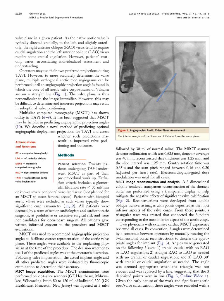
vtocrou
Tppwapbi
um(a
oaasdsnwe
apsuFaeMpkH
fdwt0(mMvam(oitc
rb3poowwwedG
Aa
C
L
Mc
R
Tv
J A C C : C A R D I O V A S C U L A R I N T E R V E N T I O N S , V O L . 3 , N O . 1 1 , 2 0 1 0
N O V E M B E R 2 0 1 0 : 1 1 5 7 – 6 5
Gurvitch et al.
MSCT to Predict TAVI Deployment Projections
1158
alve plane in a given patient. As the native aortic valve isypically directed cranially, to the left, and slightly anteri-rly, the right anterior oblique (RAO) views tend to requireaudal angulation and the left anterior oblique (LAO) viewsequire some cranial angulation. However, patients’ anat-my varies, necessitating individualized assessment andnderstanding.Operators may use their own preferred projections during
AVI. However, to more accurately determine the valvelane, multiple orthogonal aortic root angiograms can beerformed until an angiographic projection angle is found inhich the base of all aortic valve cusps/sinuses of Valsalva
re on a straight line (Fig. 1). The valve plane is thuserpendicular to the image intensifier. However, this maye difficult to determine and incorrect projections may resultn suboptimal valve positioning.
Multislice computed tomography (MSCT) has showntility in TAVI (6–9). It has been suggested that MSCTay be helpful in predicting angiographic projection angles
10). We describe a novel method of predicting optimalngiographic deployment projections for TAVI and assess
whether such predictions mayresult in improved valve posi-tioning and outcomes.
Methods
Patient selection. Twenty pa-tients undergoing TAVI under-went MSCT as part of theirpre-procedural work up. Exclu-sion criteria included a glomer-ular filtration rate � 35 ml/min
r known severe peripheral vascular disease (not planned forn MSCT to assess femoral access). Patients with bicuspidortic valves were excluded as such valves typically showignificant cusp asymmetry (11,12). All patients wereeemed, by a team of senior cardiologists and cardiothoracicurgeons, at prohibitive or excessive surgical risk and wereot candidates for open-heart surgery. All patients gaveritten informed consent to the procedure and MSCT
valuations.MSCT was used to recommend angiographic projection
ngles to facilitate correct representation of the aortic valvelane. These angles were available to the implanting phy-ician at the time of the procedure. The decision whether tose 1 of the predicted angles was at the operator’s discretion.ollowing valve implantation, the actual implant angle andll other predicted angles were evaluated by fluoroscopicxamination to determine their accuracy.SCT image acquisition. The MSCT examinations wereerformed on 2 64-slice scanners (GE Healthcare, Milwau-ee, Wisconsin). From 80 to 120 ml of iodixanol 320 (GE
bbreviationsnd Acronyms
T � computed tomography
AO � left anterior oblique
SCT � multisliceomputed tomography
AO � right anterior oblique
AVI � transcatheter aorticalve implantation
ealthcare, Princeton, New Jersey) was injected at 5 ml/s r
ollowed by 30 ml of normal saline. The MSCT scanneretector collimation width was 0.625 mm, detector coverageas 40 mm, reconstructed slice thickness was 1.25 mm, and
he slice interval was 1.25 mm. Gantry rotation time was.35 s and the scan pitch ranged between 0.16 and 0.20adjusted per heart rate). Electrocardiogram-gated doseodulation was used for all cases.SCT image reconstruction and analysis. A 3-dimensional
olume-rendered transparent reconstruction of the thoracicorta was performed using a transparent display to helpitigate the negative effects of significant valve calcification
Fig. 2). Reconstructions were developed from doubleblique transverse images with points deposited at the mostnferior aspects of the valve cusps. From these points, ariangular trace was created that connected the 3 pointsorresponding to the most inferior aspect of the aortic cusps.
Two physicians with extensive cardiac MSCT experienceeviewed all cases. By convention, 3 angles were determinedy a consensus between operators by manually rotating the-dimensional aortic reconstructions to discern the appro-riate angles for implant (Fig. 3). Angles were generatedn the following 3 axes: 1) cranial-caudal with no RAOr LAO angulation; 2) straight RAO to LAO as neededith no cranial or caudal angulation; and 3) LAO 30°ith cranial or caudal angulation as needed. The angleas deemed appropriate when the triangle was not
vident and was replaced by a line, suggesting that the 3eposited points were in line (Fig. 3, Online Video 1).iven the early nature of the work and significant aortic
Figure 1. Angiographic Aortic Valve Plane Assessment
The inferior margins of the 3 sinuses of Valsalva form the valve plane.
oot/valve calcification, these angles were recorded with a

ct
1
2
3
FttPapi
am(eo
gpee
mg
le in
J A C C : C A R D I O V A S C U L A R I N T E R V E N T I O N S , V O L . 3 , N O . 1 1 , 2 0 1 0 Gurvitch et al.
N O V E M B E R 2 0 1 0 : 1 1 5 7 – 6 5 MSCT to Predict TAVI Deployment Projections
1159
onfidence and image quality consensus Likert score of 1o 3, defined as:
. Suboptimal—Evaluation is limited by motion, calcification,poor contrast opacification, and/or gating. Image qualitylimits confident angle prediction (Online Video 2).
. Adequate—The images show minimal valve plane deg-radation due to calcification, motion, or contrast issues.Angle of implant prediction can be performed withreasonable confidence.
. Excellent—The aortic valve plane is very well visualizedwithout limitations in discerning the valve cusps. Motionand calcification do not degrade image quality. Angleprediction is performed with a high degree of confidence.
or patients with differing scores, the operator endeavoredo use a prediction angle with the highest Likert score forhe actual valve implantation.ost-valve implantation angiographic evaluation. Detailedngiographic evaluation of the implanted valves waserformed in all cases. Alignment of the stent in the
Figure 2. Stepwise Approach to Construction of a 3-Dimensional Volume R
A 3-dimensional volume-rendered projection of the aorta in an 85-year-old woof the aortic cusps. The aorta is bisected from a routine coronal projection (A)orthogonal projection of the aortic root (C) is acquired using the standard oblcusps on the orthogonal projection of the root, points are deposited on thesevolume-rendered image of the ascending aorta is then created with the triang
mplanted and other predicted angles was assessed by p
nalyzing the implanted valve stent frame and deter-ining the degree of overlap of the superior cell struts
Fig. 4). The angiographic projection was defined asxcellent, satisfactory, or poor, depending on the degreef overlap as outlined here (Fig. 4):
Excellent—Gap between superior valve struts is withinhalf a cell height.
Satisfactory—Gap between superior valve struts is be-tween half to a whole cell height.
Poor—Gap between superior valve struts is greater thanthe height of a full cell.
To assess the accuracy of MSCT angle prediction, angio-raphic evaluation was performed in each projection angleredicted by MSCT, allowing for post-implant assessment ofach of the 3 predicted angles in all 20 patients (60 anglesvaluated).
To determine the accuracy of the actual final deploy-ent angle, the deployment angle in the MSCT-guided
roup was compared with the proceeding 20 consecutive
ed Image of the Aortic Root
ith aortic stenosis is reconstructed with points denoting the inferior marginate a sagittal oblique multiplanar reformat (B). From the sagittal oblique, anorkstation tool. After scrolling to the most inferior margins of the aorticinferior margins and linked in a triangular fashion (D). A 3-dimensionalplace.
ender
man wto creique wmost
atients who underwent TAVI without angle prediction
uctDtcLpuiA
mscW
Dieppi
the a
J A C C : C A R D I O V A S C U L A R I N T E R V E N T I O N S , V O L . 3 , N O . 1 1 , 2 0 1 0
N O V E M B E R 2 0 1 0 : 1 1 5 7 – 6 5
Gurvitch et al.
MSCT to Predict TAVI Deployment Projections
1160
sing MSCT (non–MSCT-guided group). In the latterases, only orthogonal aortic root angiography was usedo assess the aortic valve plane before implantation.etermining an ideal deployment angle curve using CT:he “line of perpendicularity.” To determine the averageranial or caudal angulations required across the RAO-to-AO axis to result in correct perpendicular valve implantrojections, a retrospective analysis of patients who hadndergone MSCT or DynaCT imaging after TAVI at ournstitution was performed. In cases using DynaCT (SiemensG, Erlangen, Germany), the angiographic C-arm using a
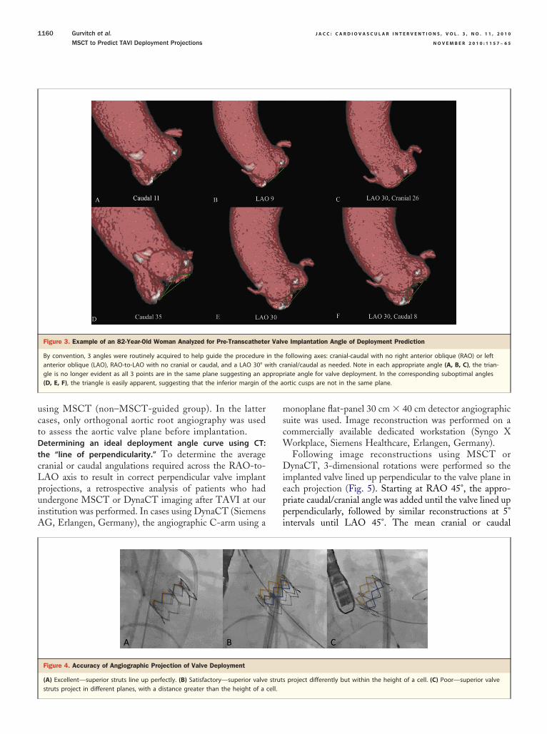
Figure 3. Example of an 82-Year-Old Woman Analyzed for Pre-Transcathete
By convention, 3 angles were routinely acquired to help guide the procedureanterior oblique (LAO), RAO-to-LAO with no cranial or caudal, and a LAO 30° wgle is no longer evident as all 3 points are in the same plane suggesting an ap(D, E, F), the triangle is easily apparent, suggesting that the inferior margin of
Figure 4. Accuracy of Angiographic Projection of Valve Deployment
(A) Excellent—superior struts line up perfectly. (B) Satisfactory—superior valve
struts project in different planes, with a distance greater than the height of a cell.onoplane flat-panel 30 cm � 40 cm detector angiographicuite was used. Image reconstruction was performed on aommercially available dedicated workstation (Syngo X
orkplace, Siemens Healthcare, Erlangen, Germany).Following image reconstructions using MSCT orynaCT, 3-dimensional rotations were performed so the
mplanted valve lined up perpendicular to the valve plane inach projection (Fig. 5). Starting at RAO 45°, the appro-riate caudal/cranial angle was added until the valve lined uperpendicularly, followed by similar reconstructions at 5°ntervals until LAO 45°. The mean cranial or caudal
e Implantation Angle of Deployment Prediction
following axes: cranial-caudal with no right anterior oblique (RAO) or leftanial/caudal as needed. Note in each appropriate angle (A, B, C), the trian-iate angle for valve deployment. In the corresponding suboptimal anglesortic cusps are not in the same plane.
project differently but within the height of a cell. (C) Poor—superior valve
r Valv
in theith crpropr
struts

psSmiuasauv
R
Be(gTntnCpitpoodPc
2o(bToRsp3
and s
J A C C : C A R D I O V A S C U L A R I N T E R V E N T I O N S , V O L . 3 , N O . 1 1 , 2 0 1 0 Gurvitch et al.
N O V E M B E R 2 0 1 0 : 1 1 5 7 – 6 5 MSCT to Predict TAVI Deployment Projections
1161
rojection needed at each point along the RAO to LAOpectrum was then determined and plotted.tatistical analysis. Continuous variables are described asean � SD when normally distributed or as medians with
nterquartile ranges (IQR) when not. Normality was testedsing the Shapiro-Wilk goodness-of-fit test. Categorical vari-bles are described by frequencies and percentages. Compari-on of categorical variables was performed using a chi-squarenalysis. Comparisons of continuous variables were performedsing Student t tests. Analyses were performed using SPSSersion 17.0 (SPSS Inc., Chicago, Illinois).
esults
aseline characteristics. There were no significant differ-nces between the 2 groups (Table 1). The mean ageMSCT-guided: 83.2 � 5.2 years vs. non–MSCT-uided: 84.6 � 5.8 years, p � 0.68), the mean Society ofhoracic Surgery risk score (MSCT-guided: 8.6 � 3.4% vs.on–MSCT-guided: 8.4 � 3.6%, p � 0.45), and propor-ion of transfemoral procedures (MSCT-guided 80% vs.on–MSCT-guided: 70%, p � 0.47) were all similar.linical outcomes. Forty patients underwent TAVI. Overallrocedural success was 100% (Table 2). There was no
n-hospital mortality. There were no cases of valve emboliza-ion or coronary obstruction. There were similar rates ofost-procedural aortic incompetence, all of which were trivialr mild. There were no cases of worsening mitral regurgitationr mitral valve impingement. No patients suffered renal failureue to the contrast load from the MSCT scan.redicting valve plane orientation using MSCT. In the
Figure 5. Post-Implant CT Evaluation to Determine the Line of Perpendicula
Example of an 81-year-old man after transcatheter implantation of a 26-mm bvalve in projections RAO 30°/caudal 30°, posterior-anterior–caudal 10° and strapendicularity at projections RAO 30°/cranial 20°, posterior-anterior–caudal 45°,
ranial-caudal axis, the median predicted angle was caudal
0° (IQR: 7° to 40°). In the straight RAO-LAO (no cranialr caudal) axis, the median predicted angle was LAO 14°IQR: 9° to 24°). In the LAO 30° � cranial/caudal axis, allut 4 patients required the addition of cranial angulation.hree patients had a predicted cranial-caudal axis projectionf caudal �45°, and 1 patient had a predicted straightAO-LAO projection LAO �45°. The latter patient had
evere spinal kyphoscoliosis and an unfolded aorta withredicted cranial-caudal axis angle of caudal 43° and LAO0° � cranial/caudal axis angle of LAO 30°/caudal 14°.
expandable valve. The top 3 images show optimal perpendicularity of theAO 10°. In the same case, the bottom 3 rows show suboptimal valve per-traight LAO 40°. CAUD � caudal; other abbreviations as in Figure 3.
Table 1. Baseline Characteristics
No MSCT AnglePrediction(n � 20)
With MSCT AnglePrediction(n � 20)
pValue
Age, yrs 84.6 � 5.8 83.2 � 5.2 0.68
Male 55 50 0.75
Transfemoral procedure 70 80 0.47
Coronary artery disease 65 70 0.72
Prior thoracotomy 20 30 0.47
Pulmonary disease 25 25 1.00
Cerebrovascular disease 30 25 0.72
Peripheral vascular disease 35 20 0.29
GFR �60 ml/min 65 70 0.72
Ejection fraction �50% 35 35 1.00
Mitral regurgitation � moderate 10 15 0.63
Baseline NYHA functional class III/IV 90 95 0.55
STS score, % 8.4 � 3.6 8.6 � 3.4 0.45
Values are mean � SD or %.
GFR � glomerular filtration rate; MSCT � multislice computed tomography; NYHA � New York
rity
alloonight L
Heart Association; STS � Society of Thoracic Surgeons.

Upi4wcw3apMI2MiMoi
uaAwfsepIacpsLae
aw
J A C C : C A R D I O V A S C U L A R I N T E R V E N T I O N S , V O L . 3 , N O . 1 1 , 2 0 1 0
N O V E M B E R 2 0 1 0 : 1 1 5 7 – 6 5
Gurvitch et al.
MSCT to Predict TAVI Deployment Projections
1162
se of MSCT-predicted angles during TAVI. An angiographicrojection angle as predicted by MSCT was used as the finalmplant angle by the TAVI operator in 16 cases (80%). Of
cases where predicted angles were not used, in 3 the valveas deployed in a satisfactory or excellent projection, and in 1
ase the projection was poor. The Likert scores in these 4 casesere generally low (only 2 of 12 predicted angles with Likert), indicating poor MSCT image quality. Of the 12 predictedngles in these 4 patients, 58.3% were subsequently assessed asoor. In the case where deployment was in a poor projection,SCT predicted 2 excellent angles and 1 poor.
mpact of MSCT angle prediction on valve deployment. The0 patients who underwent TAVI with pre-proceduralSCT angle prediction were compared with the proceed-
ng consecutive cohort of 20 patients that had TAVI withoutSCT angle prediction. When MSCT was used, an excellent
r satisfactory final valve implant projection angle was achievedn 18 cases (90%) versus 13 cases (65%) when MSCT was not
Figure 6. Accuracy of Valve Deployment Without Versus With MSCTAngle Prediction
When multislice computed tomography (MSCT) was used, an excellent orsatisfactory final valve implant projection angle was achieved in 90% of
Table 2. Procedural Characteristics
No MSCT
Procedural success
In-hospital mortality
Aortic mean gradient pre-procedure, mm Hg 4
Aortic mean gradient post-procedure, mm Hg 1
AVA pre-procedure, mean cm2
AVA post-procedure, mean cm2
Aortic regurgitation � moderate
Mitral regurgitation grade increase �1
New permanent pacemaker
Valve embolization
Coronary vessel occlusion
Values are n (%), n, or mean � SD.
AVA � aortic valve area; other abbreviations as in Table 1.
cases versus 65% of cases when MSCT was not used (p � 0.06).
sed (p � 0.06) (Fig. 6). The reduction in poor projectionngles was from 35% to 10% (p � 0.06).ccuracy of MSCT angle prediction. Angiographic imagesere obtained in all the different MSCT-predicted angles
or each patient after valve implantation. The accuracy wasimilarly determined by the perpendicularity of the valve inach of the predicted angle projections. Overall, MSCTredicted an excellent or satisfactory angle in 75% of cases.mpact of optimal MSCT images. The accuracy of MSCTngle prediction was analyzed according to the Likertonfidence scale. Likert confidence scores were 1 for 15redictions, 2 for 14, and 3 for 31. In those with Likertcore of 1, 73% of predicted angles were poor. In those withikert score 2, 57% were excellent, 29% were satisfactory,nd 14% were poor. In those with Likert score 3, 74% werexcellent, 20% were satisfactory, and 6% were poor (Fig. 7).
The Likert score was generally similar for all 3 predictedngles in any given patient. In 95% of cases, all Likert scoresere either the same or within 1 score for all projections.
Figure 7. Accuracy of Prediction Angle According to the LikertConfidence Score
If multislice computed tomography is of high quality, the predictive accu-
Prediction0)
With MSCT Angle Prediction(n � 20) p Value
0) 20 (100) 1.00
0 N/A
5.5 44.4 � 18.4 0.44
.5 10.7 � 3.1 0.42
.2 0.6 � 0.2 0.45
.3 1.5 � 0.4 0.81
0 N/A
0 N/A
1 0.55
0 N/A
0 N/A
racy is high. If the quality is low, the predictive accuracy is low.
Angle(n � 2
20 (10
0
0.1 � 1
1.8 � 4
0.7 � 0
1.5 � 0
0
0
2
0
0

Dopu1rat
rtTgL
D
Tpatiiafpw
appIaatOtn“cd
ppvphApipntc
J A C C : C A R D I O V A S C U L A R I N T E R V E N T I O N S , V O L . 3 , N O . 1 1 , 2 0 1 0 Gurvitch et al.
N O V E M B E R 2 0 1 0 : 1 1 5 7 – 6 5 MSCT to Predict TAVI Deployment Projections
1163
etermination of the line of perpendicularity: the spectrumf angiographic projections resulting in valve implantationerpendicular to the valve plane. Twenty-seven patientsnderwent CT evaluation following TAVI (15 had MSCT and2 had DynaCT). The resulting mean caudal or cranial angulationequired at each angle across the RAO-to-LAO spectrum followscurve crossing the cranial-caudal axis at caudal 10° � 14°, and
he RAO-to-LAO axis at LAO 10° � 14° (Fig. 8).In the RAO projection, caudal angulation is usually
equired to obtain the correct perpendicular projection. Inhe LAO projection, cranial angulation is usually needed.he amount of caudal angulation needed at RAO 45° isreater than the amount of cranial angulation needed atAO 45° (RAO 45°/caudal 40° vs. LAO 45°/cranial 27°).
iscussion
he present study demonstrates that MSCT can correctlyredict angiographic projection angles perpendicular to theortic valve plane and help guide TAVI procedures. Predic-ion is best when MSCT image quality is optimal, resultingn greater accuracy of valve deployment, with a reduction inmplantation at nonperpendicular angles. The MSCT andngiographic 3-dimensional reconstructions (DynaCT) per-ormed after implantation also demonstrate the average “line oferpendicularity,” showing that valves may be deployed in aide range of RAO or LAO projections as long as the
Figure 8. Line of Perpendicularity
The graph represents the mean caudal or cranial angulation needed at the sp
perpendicularity to the X-ray beam. Abbreviations as in Figures 3 and 5.ppropriate caudal or cranial angulation is added—with RAOrojections generally needing caudal angulations and LAOrojections needing cranial angulations.mportance of determining the correct valve plane. As theortic valve and root are 3-dimensional structures viewed on2-dimensional screen during TAVI, correct evaluation of
he aortic valve plane is necessary for a successful procedure.perators need to choose an implant projection in which
he implanted valve is perpendicular or orthogonal to theative valve plane. If 1 or more of the aortic leaflets isoff-axis,” accurate positioning is difficult to achieve, in-reasing the risk of malposition, embolization, and proce-ural complications.Evaluation of the native aortic valve plane is generally
erformed by angiographic root angiograms in differentrojections until the valve cusps line up such that the nativealve plane is perpendicular to the image intensifier. In someatients, this may be difficult to achieve, as the presence ofeavily calcified leaflets may obscure the remaining cusps.dditional contrast is often required to find an acceptablerojection. An advantage of MSCT lies in the ability to acquiremages before the procedure and then analyze off-line to helplan the procedure. Peripheral vasculature/femoral access, an-ular dimensions, extent and distribution of leaflet calcifica-ion, and coronary artery position and relationship to bulkyalcified leaflets can be assessed concurrently (6–9).
of right-to-left anterior oblique projections (5° intervals) to achieve valve
ectrum
Ugogovampm
aawstttpameadoaRpcdso
ia3puaiac
togeIt(grds
scMt
torevfiartaLdlptcpRvdcocaitsoocSupeaptasspvptdcp
J A C C : C A R D I O V A S C U L A R I N T E R V E N T I O N S , V O L . 3 , N O . 1 1 , 2 0 1 0
N O V E M B E R 2 0 1 0 : 1 1 5 7 – 6 5
Gurvitch et al.
MSCT to Predict TAVI Deployment Projections
1164
tility of MSCT angle prediction. Patients with MSCT-uided TAVI had more frequent implantation in excellentr satisfactory projections compared with non–MSCT-uided procedures (aortography alone). The comparison isne of MSCT prediction in conjunction with aortographyersus aortography alone. Multislice CT is additive toortography, especially in circumstances where the latteray be inadequate in confidently determining the valve
lane. Eventually, real-time 4-dimensional coregistered CTay reduce the need for aortic root angiography.We chose to predict 3 angles, but unlimited reformations
nd angle combinations can be achieved. Our choice ofxes—cranial-caudal with no RAO or LAO, RAO-LAOith no cranial or caudal, and LAO 30 � cranial/caudal—
tems from prior experience and practical considerations inhe catheterization laboratory. Future groups using thisechnology may choose different axes or angles with whichhey are more familiar, with any point along the line oferpendicularity of a given patient being potentially appropri-te. Practical considerations with regard to radiation equip-ent and ergonomics are also important to consider. For
xample, if in the cranial-caudal axis, a very steep caudalngle (�40°) is predicted for a given patient, this may beifficult to achieve given the constraints of the patient’s bodyn the table. Adding LAO may result in less caudalngulation being required. Similarly, very steep LAO orAO angles may be impractical for the operator given thehysical position of the image intensifier or detector. Anglehoice may differ for transfemoral versus transapical proce-ures for similar reasons, with transfemoral operators pos-ibly preferring straight or LAO projections and transapicalperators preferring RAO (�caudal) projections.Recent studies have highlighted the potential role of MSCT
n TAVI (6–9). Kurra et al. (10) compared imaging of theortic root by X-ray angiographic planar imaging and-dimensional CT, suggesting the latter can aid in pre-rocedural planning. Our study further extends the clinicaltility of MSCT in the context of TAVI by demonstrating thebility to predict accurate deployment angles, resulting inmproved valve deployment accuracy and reduction of incorrectngle choices, and providing operators with the average cranial oraudal angulations needed for a given RAO or LAO projection.
Our center has a large experience with TAVI. Despitehis experience, MSCT was able to improve the frequencyf correct angle choice. Multislice CT may have an evenreater impact on the results of groups beginning theirxperience with TAVI.mportance of optimal MSCT images. We found our predic-ions to be most accurate when the MSCT images were idealwith a high Likert confidence grade). When the confidencerade was poor, 73% of the predicted angles would haveesulted in suboptimal deployment angles. When the confi-ence grade was high, �90% of angles were excellent or
atisfactory. This has important implications for the wide- tpread use of such technology, especially during the learningurve of each center. TAVI operators should be aware that
SCT-generated predicted angles should be used with cau-ion when the source MSCT images are suboptimal.
During reconstruction of the aortic root, particular atten-ion must be paid to determining the most inferior marginf each aortic cusp from the orthogonal projection of theoot. By linking these points in a triangular fashion, withach cusp represented by a point of the triangle, the correctalve plane can be determined even in patients with un-olded, horizontal, or vertical aortas. By rotating the imagen 3 dimensions using the triangle for the valve plane, eachngiographic projection in which the triangle “disappears”epresents perpendicularity to the valve plane. However, ifhe inferior margin is chosen erroneously for 1 or moreortic cusps, the valve plane chosen may be incorrect.ine of perpendicularity. Our post-implant CT analysisemonstrates that the average line of perpendicularity fol-
ows a curve across the RAO-LAO spectrum. A line oferpendicularity can be generated for each patient beforehe procedure, with essentially infinite angles along it thatould achieve perpendicularity to the valve plane in a givenatient. Given the typical plane of the native aortic valve,AO views tend to require caudal angulation and LAO
iews some cranial angulation. Operators may choose anyegree of RAO to LAO as long as the appropriate cranial oraudal angulation is added. For the average patient, the linef perpendicularity runs from a RAO-caudal projection,rosses the posterior-anterior projection at about 10° caudalnd the straight LAO at about 10°, and then continues withncreasing cranial requirements for steeper LAO projec-ions. Consequently, if we are unable to perform MSCTecondary to significant renal dysfunction, we routinely dour initial screening aortogram at either straight caudal 10°r LAO 10° and make small adjustments accordingly. Thisan decrease both contrast and radiation exposure.pecial considerations. Some patients will require steep andnusual projections to achieve perpendicularity to the valvelane. This is particularly so in patients with musculoskel-tal abnormalities, kyphoscoliosis, or horizontal or unfoldedortas, and here lies a particular advantage of MSCT anglerediction. In such patients, even if image quality is subop-imal, MSCT will allude to the need for an unusual anglend demand closer scrutiny. For example, in 1 patient withevere kyphoscoliosis and an unfolded aorta, an unusuallyteep LAO caudal angle was needed. In this case, MSCTredicted an angle of LAO 30°/caudal 14° (Likert 1). Thealve was deployed in this angle and resulted in poorrojection (just over 1 cell width) according to our defini-ions. However, this was not far from an excellent perpen-icular projection, which was determined at LAO 45°/audal 14° after implant. When viewed in posterior-anteriorrojection with no caudal or cranial and no RAO or LAO,
he valve was “down the barrel”; thus, had we used such a
phanaOudhWtpsriSwdoPifssraSpcpwicdir
Tcak
leLbtu
C
Pm
ivdsg
RPb
R
1
1
1
1
Kg
J A C C : C A R D I O V A S C U L A R I N T E R V E N T I O N S , V O L . 3 , N O . 1 1 , 2 0 1 0 Gurvitch et al.
N O V E M B E R 2 0 1 0 : 1 1 5 7 – 6 5 MSCT to Predict TAVI Deployment Projections
1165
rojection, achieving correct positioning would have beenighly unlikely. Hence, even though MSCT did not predictperfect angle in this case, it highlighted an unusual angleeed, and brought us within 15° of a perfect projection, andvoided possible malposition.ther technologies to aid valve positioning. New systemssing progress in image acquisition, angiographic 3-imensional reconstructions, and software developmentave recently been applied to assist with valve positioning.hereas DynaCT was used only for post-implant evalua-
ion in the current study, this modality may also be usedre- or periprocedurally to evaluate deployment anglesimilar to pre-procedural scanning with MSCT. Aorticeconstructions and image interrogations are available rap-dly during the procedure. The Shina Systems (Shinaystems Ltd., Caesarea, Israel) aortic valve assistance soft-are can also be used to help integrate 3-dimensional CTata with angiograms and live fluoroscopy and help predictptimal valve plane orientation. Our center has also used theaieon C-THV (Paieon Inc., Rosh Ha’ayin, Israel), which
s an image acquisition and processing system designed toacilitate TAVI. This stand-alone, real-time system is de-igned to assist with valve positioning, selection of valveize, and post-implant evaluation (13). Further evaluation isequired to determine whether similar results can bechieved using these modalities.tudy limitations. Despite multiple predicted angles of de-loyment for each patient in the MSCT group, the finalhoice of angiographic projection or whether to use 1 of theredicted angles was left at the operator’s discretion. Thisas required given the early nature of the work, because
ncorrectly predicted MSCT angles may have resulted in direlinical outcomes. In the 4 cases where the operator chose aifferent angle, this was largely due to suboptimal MSCT
mages. As the technique is improved over time, greatereliance and trust in the predicted angles will be possible.
The MSCT scans were not performed at the same time asAVI, thus unusual patient positioning during either pro-
edure may have led to inaccurate angle assessment. Tovoid this, we developed protocols to ensure all patients areept supine during both their diagnostic tests and TAVI.The similarity of clinical outcomes may be viewed as a
imitation of this study. However, our center is highly experi-nced in TAVI with excellent clinical outcomes as a whole.arger numbers are likely to be required to show clinicalenefits in experienced hands, although centers commencingheir TAVI experience may find use of this technology partic-larly beneficial earlier in the learning curve.
onclusions
re-procedural MSCT predicts optimal angiographic deploy-
ent projections in which transcatheter valves should be Fmplanted. Using such predictions improves the accuracy ofalve deployment and may reduce malposition. An idealeployment angle curve or line of perpendicularity that tran-itions from RAO to LAO and caudal to cranial can beenerated.
eprint requests and correspondence: Dr. John G. Webb, St.aul’s Hospital, 1081 Burrard Street, Vancouver, British Colum-ia V6Z 1Y6, Canada. E-mail: [email protected].
EFERENCES
1. Webb JG, Altwegg L, Boone RH, et al. Transcatheter aortic valveimplantation: impact on clinical and valve-related outcomes. Circula-tion 2009;119:3009–16.
2. Tamburino C, Capodanno D, Mule M, et al. Procedural success and30-day clinical outcomes after percutaneous aortic valve replacementusing current third-generation self-expanding CoreValve prosthesis.J Invasive Cardiol 2009;21:93–8.
3. Al Ali AM, Altwegg L, Horlick EM, et al. Prevention and manage-ment of transcatheter balloon-expandable aortic valve malposition.Catheter Cardiovasc Interv 2008;72:573–8.
4. Masson JB, Kovac J, Schuler G, et al. Transcatheter aortic valveimplantation: review of the nature, management, and avoidance ofprocedural complications. J Am Coll Cardiol Intv 2009;2:811–20.
5. Wong DR, Ye J, Cheung A, Webb JG, Carere RG, Lichtenstein SV.Technical considerations to avoid pitfalls during transapical aortic valveimplantation. J Thorac Cardiovasc Surg 2010;140:196–202.
6. Leipsic J, Wood D, Manders D, et al. The evolving role of MDCT intranscatheter aortic valve replacement: a radiologists’ perspective. AJRAm J Roentgenol 2009;193:W214–9.
7. Ng AC, Delgado V, Van der Kley F, et al. Comparison of aortic rootdimensions and geometries before and after transcatheter aortic valveimplantation by 2-and 3-dimensional transesophageal echocardiogra-phy and multislice computed tomography. Circ Cardiovasc Imaging2010;3:94–102.
8. Tops LF, Wood DA, Delgado V, et al. Noninvasive evaluation of theaortic root with multislice computed tomography implications fortranscatheter aortic valve replacement. J Am Coll Cardiol Img 2008;1:321–30.
9. Wood DA, Tops LF, Mayo JR, et al. Role of multislice computedtomography in transcatheter aortic valve replacement. Am J Cardiol2009;103:1295–301.
0. Kurra V, Kapadia SR, Tuzcu EM, , et al. Pre-procedural imaging ofaortic root orientation and dimensions: comparison between X-rayangiographic planar imaging and 3-dimensional multidetector com-puted tomography. J Am Coll Cardiol Intv 2010;3:105–13.
1. Sabet HY, Edwards WD, Tazelaar HD, Daly RC. Congenitallybicuspid aortic valves: a surgical pathology study of 542 cases (1991through 1996) and a literature review of 2,715 additional cases. MayoClin Proc 1999;74:14–26.
2. Roberts WC. The congenitally bicuspid aortic valve. A study of 85autopsy cases. Am J Cardiol 1970;26:72–83.
3. Wijesinghe N, Masson JB, Nietlispach F, et al. Paieon’s C-THVsystem—A novel real-time image processor to facilitate transcatheteraortic valve implantation (TAVI). J Am Coll Cardiol 2010;55 Suppl1:A147.e1384.
ey Words: aortic stenosis � multislice computed tomo-raphy � transcatheter aortic valve implantation.
APPENDIX
or videos, please see the online version of this article.
Copyright © 2022 FDOKUMEN