MULTIPROCESS DC INVERTER MANUAL - AIMS Industrial
56
MULTIPROCESS DC INVERTER MANUAL / CONDITIONS APPLY CONDITIONS APPLY
-
Upload
khangminh22 -
Category
Documents
-
view
0 -
download
0
Transcript of MULTIPROCESS DC INVERTER MANUAL - AIMS Industrial

MULTIPROCESS DC INVERTER MANUAL
/Plug
size
Duty
cycle
Generator
Material
Plate
Thickness
32kVA
3 Phase
60% @ 500Amps
Maximum30mm
XWire Feeder
• Mild Steel • Carbon Steel• Aluminium (MIG ONLY)
• StainlessMaterial
• Mild Steel • Stainless• Aluminium (MIG ONLY)
• Brass• Copper
Plug
size
Duty
cycle
Generator
Material
Plate
Thickness
18kVA
3 Phase
60% @ 350Amps
Maximum16mm
• Mild Steel • Stainless• Aluminium (MIG ONLY)
• Brass• Copper
XWire Feeder
Material• Mild Steel • Carbon Steel• Aluminium (MIG ONLY)
• Stainless
CONDITIONSAPPLY
CONDITIONSAPPLY
CONDITIONSAPPLY
CONDITIONSAPPLY

2
Thank you for choosing a BOSSWELD MST 350X/MST 500X Inverter DC MIG WelderIn this manual you will find instructions on how to set up your welder along with general welding information, safety information and helpful tips. We encourage you to go online to our website for more tips and troubleshooting as well as many welding resources. The BOSSWELD MST 350X/MST 500X are the latest in IGBT welder technology, this multipurpose welder is very simple to set up and operate enabling the user to complete high quality welds in MIG Gas / MMA -Stick electrode / Air ARC Gouging / TIG - Scratch Start. A great all round welder for the serious tradesman that want’s to take on bigger welding projects.
Every effort has been made to ensure that this manual has been prepared accurately, however errors and omissions are excepted.
BOSSWELD is a trademark of Dynaweld Industrial Supplies Pty Ltd.
M MIG• Simple to learn • MIG Wire is fed through the gun to create the weld pool• Gas or flux prevents oxidisation in the weld• Weld with or without gas• Point and pull the trigger• Great for maintenance, small projects
& automotive repairs METAL TYPES Mild steel, stainless steel & aluminium
S STICK• Easiest process to learn• Best choice for quick repairs• Slower than MIG welding• Forgiving in dirty/rusty environments• Not recommended for thin sheet metal welding METAL TYPES Mild steel, stainless steel & cast iron
T TIG• Gives a better weld finish• Accurate heat control• Considered the most challenging process to learn• Good way to weld thin material• Argon gas is required METAL TYPES Mild steel, stainless steel & aluminium
P PLASMA CUTTING P• Wide range of uses to cut conductive metals• Uses an accelerated jet of hot plasma• High speed/low cost cutting method• Used extensively replacing gas cutting methods• Air compressor is required METAL TYPES Mild steel, stainless steel & aluminium

3
CONTENTS PAGE
WARRANTY 4
BOX CONTENTS 5
WARNINGS 6
MACHINE CARE / SAFETY INSTRUCTIONS 7
WORK AREA SAFETY 8
MAINTENANCE & DISPOSAL / GAS BOTTLE 9
TECHNICAL INFORMATION 10-11
FRONT & REAR PANEL LAYOUT 12
MACHINE CONTROLS PANELS 13
WIRE FEEDER LAYOUT 14
MACHINE INSIDE / DUTY CYCLE 15
WATER COOLER SET UP 16-17
WIRE SPOOL & WIRE FEED SET UP 18
MIG TORCH SETUP 19
LINER INSTALLATION / REPLACEMENT 20
DRIVE ROLLER SIZE 21
2T / 4T TRIGGER CONTROL INFORMATION 21
MIG TORCH AND CONSUMABLE CARE 22
GAS MIG WELDING SETUP 23-26
GASLESS MIG WELDING SETUP 27-30
SPOOL GUN WELDING SETUP 31-34
STANDARD WELDING PROGRAMS 35
GENERAL MIG WELDING 36-38
STICK / MMA WELDING SETUP 39-40
GENERAL MMA WELDING 41
TIG WELDING SETUP 42-43
LIFT ARC TIG 44
TUNGSTEN PREPARATION 45
GENERAL TIG WELDING 46
MIG TORCH PARTS 47-48
17 TIG TORCH PARTS 49
HELPFUL INFORMATION & TROUBLE SHOOTING 50-53

4
WARRANTY
This warranty is in addition to the statutory warranty provided under Australian Consumer Law, but does not include damage resulting from transport, misuse, neglect or if the product has been tampered with.The product must be maintained as per this manual, and installed and used according to these instructions on an appropriate power supply. The product must be used in accordance with industry standards and acceptable practice.This warranty covers the materials used to manufacture the machine and the workmanship used to produce the item. This Warranty does not cover damage caused by:1. Normal wear and tear due to usage2. Misuse /abuse or Neglect of the item3. Transport / handling breakages4. Lack of maintenance, care and cleaning5. Environmental factors, such as usage in temperatures exceeding 40 degrees, above 1000mt sea level, rain,
water, excessive damp, cold or humid conditions. 6. Improper setup or installation7. Use on Incorrect voltage or non authorised electrical connections and plugs8. Use of non standard parts9. Repair, case opening, tampering with, modifications to any part of the item by non authorised BOSSWELD
repairers.This warranty covers the machine only and does not include Torches, Leads, Earth Clamps, Electrode holders, Plasma Torches, Tig Torches and any of the parts on those items unless there is a manufacturing fault.
1. REGISTRATIONPurchasers are encouraged to register for warranty on our website. www.bossweld.com.au/warranty Product must be registered to receive full 5 year warranty. 3 year standard warranty applies if the product is not registered online.
2. TIME PERIOD - 5 Years (when registered online)When the welder has been registered online, a warranty claim must be made within 5 years from the date of purchase. If the welder has not been registered online, a warranty claim must be made within 3 years from the date of purchase. Any claim must include proof of purchase.
3. HOW TO MAKE A CLAIM - NEED SOME HELP?• Visit our website www.bossweld.com.au/troubleshooting for many helpful tips and guides to assist with
the setup and usage of your new machine. Still stuck….?• Call the BOSSWELD Helpdesk on 1300 899 710 for over the phone assistance.• If the machine is not operational then return the item to the place of purchase.
Note:If this welders duty cycle is exceeded the welder will enter “thermal overload” which will automatically stop the welding output in order to protect, both the user and the welder. You will know the welder has gone into thermal overload when the overload error indicator light is illuminated. The welder will then cool itself down, and once the overload error indicator light is no longer illuminated, welding can then re-commence. Please note. Exceeding the machine’s duty cycle, cannot be considered grounds for warranty or return.
BOSSWELD MAKES NO OTHER WARRANTY, EXPRESS OR IMPLIED. THIS WARRANTY IS EXCLUSIVE AND IN LIEU OF ALL OTHERS, INCLUDING, BUT NOT LIMITED TO ANY WARRANTY OF MERCHANTABILITY OR FITNESS FOR ANY PARTICULAR PURPOSE.
CONDITIONSAPPLY
CONDITIONSAPPLY
CONDITIONSAPPLY
CONDITIONSAPPLY

5
BOSSWELD MST 350X/MST 500X Inverter MIG/MMA Welder Box Contents
1. BOSSWELD X Series Power source MIG/MMA Welder On Trolley (MST 500X shown)
2. Mobile X Wire Feeder
3. 4 metre Ergon BZ501 MIG Torch (500X)
3. 3 metre Ergon BZ36 MIG Torch (350X)
4. 3 metre Electrode Holder Lead
5. 5 metre 500Amp Earth Clamp
6. 2 metre Gas Hose
7. 10 metre Interconnecting cables
8. Argon Regulator Twin Gauge
9. 350X - Drive Roller (Installed in Machine 0.8-1.0) - not shown
350X - Drive Roller 0.9/1.2mm (Spare Drive Roller) - not shown
9. 500X - Drive Roller (Installed in Machine 0.8-1.0) - not shown
500X - Drive Roller 0.9/1.2mm (Spare Drive Roller) - not shown
10. User Manual - not shown2
3
4
56
8
Note: Pictures may vary from your machine model
1
7

6
The device and packaging material are not toys! Children must not be allowed to play with the machine and its accessories. Plastic parts and packaging are choking risks for children. • Open the packaging and remove the welder carefully.• Check that the delivery is complete.• If possible, store the packaging until the warranty period has expired.
PERSONAL PROTECTIVE EQUIPMENT (PPE)
GLOVES AND PROTECTIVE CLOTHINGUse protective gloves and fire resistant protective clothing when welding. Avoid exposing skin to ultraviolet rays produced by the arc.
WELDING HELMETUnder no circumstances should the welder be operated unless the operator is wearing a welding helmet to protect the eyes and face. There is serious risk of eye damage if a helmet is not used. The sparks and metal projectiles can cause serious damage to the eyes and face. The light radiation produced by the arc can cause damage to eyesight, and burns to skin. Never remove the welding helmet whilst welding.
SAFETY GLASSESAfter welding use appropriate safety glasses when brushing, chipping or grinding the slag from the weld.
OTHER PERSONSEnsure that other persons are screened from the welding arc and are at least 15 metres away from the work piece. Always ensure that the welding arc is screened from onlookers, or people just passing by. Use screens if necessary, or non-reflecting welding curtain. Do not let children or animals have access to the welding equipment or to the work area.
SWITCHING OFFWhen the operator has finished welding they must switch the welder off. DO NOT put the electrode holder down with the welder switched ON. When leaving the welder unattended, move the ON/OFF switch to the OFF position and disconnect the welder from the electrical mains supply. Do not leave hot material unattended after welding.
FUMES &GASES ARE DANGEROUSSmoke and gas generated whilst welding or cutting can be harmful to people’s health. Weld-ing produces fumes and gases. Breathing these fumes and gases can be hazardous to your health.• Do not breathe the smoke and gas generated whilst welding or cutting, keep your head out of the fumes• Keep the working area well ventilated, use fume extraction or ventilation to remove welding fumes and gases.• In confined or heavy fume environments always wear an approved air-supplied respirator. Welding fumes and gases can displace air and lower the oxygen level causing injury or death. Be sure the breathing air is safe.• Do not weld in locations near de-greasing, cleaning, or spraying operations. The heat and rays of the arc can react with vapours to form highly toxic and irritating gases.• Materials such as galvanized, lead, or cadmium plated steel, containing elements that can give off toxic fumes when welded. Do not weld these materials unless the area is very well ventilated, and or wearing an air supplied respirator.
WARNING

7
Keep the welding cables, earth clamp and electrode holder in good condition. Failure to do this can result in poor welding quality, which could be dangerous in structural situations.Prior to use, check for breakage of parts and any other conditions that may affect operation of the welder. Any part of the welder that is damaged should be carefully checked to determine whether it will perform its intended function whilst being safe for the operator. Any part that is damaged should be properly repaired, or replaced by an authorised service centre. IMPROPER USEIt is hazardous to use the welding machine for any work other than that for which it was designed e.g. do not use welder for thawing pipes. HANDLING Ensure the handle is correctly fitted. As welding machines can be heavy, always use safe lifting practices when lifting. POSITION AND HANDLINGTo reduce risk of the machine being unstable / danger of overturning, position the welding machine on a horizontal surface that is able to support the machine weight. Operators MUST NOT BE ALLOWED to weld in raised positions unless safety platforms are used.
WARNINGThe user of this welder is responsible for their own safety and the safety of others. It is important to read, understand and respect the contents of this user guide. When using this welder, basic safety precautions, including those in the following sections must be followed to reduce the risk of fire, electric shock and personal injury. Ensure that you have read and understood all of these instructions before using this welder. Persons who are not familiar with this user guide should not use this welder. Keep this booklet in a safe place for future reference. TRAININGThe operator should be properly trained to use the welding machine safely and should be informed about the risks relating to arc welding procedures. This user guide does not attempt to cover welding technique. Training should be sought from qualified / experienced personnel on this aspect, especially for any welds requiring a high level of integrity for safety. SERIOUS FIRE RISKThe welding process produces sparks, droplets of fused metal, metal projectiles and fumes. This constitutes a serious fire risk. Ensure that the area in which welding will be undertaken is clear of all inflammable materials. It is also advisable to have a fire extinguisher, and a welding blanket on hand to protect work surfaces.
MACHINE CARE / SAFETY
SAFETY INSTRUCTIONS

8
Ensure a clear, well lit work area with unrestricted movement for the operator.
The work area should be well ventilated, as welding emits fumes which can be dangerous.
Always maintain easy access to the ON/OFF switch of the welder, and the electrical mains supply.
Do not expose the welder to rain and do not operate in damp or wet locations
WORK AREA
Where welding must be undertaken in environments with increased risk of electric shock, confined spaces or in the presence of flammable or explosive materials, it is important that the environment be evaluated in advance by an “expert supervisor”. It is also recommended that welding in these circumstances be carried out in the presence of persons trained to intervene in emergencies. AVOID ELECTRICAL CONTACTUse adequate electrical insulation with regard to the electrode, the work piece and any accessible earthed metal parts in the vicinity. Avoid direct contact with the welding circuit. The no load voltage between the earth clamp and the electrode can be dangerous under certain circumstances.Note: For additional protection from electric shock. It is recommended that this welder be used in conjunction with a residual current device (RCD) with rated residual current of 30MA or less.In general the use of extension leads should be avoided. If used however, ensure that the extension lead is used with the welder is of a suitable current rating and heavy duty in nature that MUST have an earth connection. If using the welder outdoors, ensure that the extension lead is suitable for outdoor use. Always keep extension leads away from the welding zone, moisture and any hot materials. WELDING SURFACESDo not weld containers or pipes that hold, or have held, flammable liquids or combustible gases or pressure. Do not weld on coated, painted or varnished surfaces as the coatings may ignite, or can give off dangerous fumes. WORK PIECE When welding, the work piece will remain at high temperature for a relatively long period. The operator must not touch the weld or the work piece unless wearing welding gloves. Always use pliers or tongs. Never touch the welded material with bare hands until it has completely cooled. VOLTAGE BETWEEN ELECTRODE HOLDERS OR TORCHESWorking with more than one welding machine on a single work piece, or on work pieces that are connected, may generate a dangerous accumulation of no-load voltage between two different electrode holders or torch-es, the value of which may reach double the allowed limit.

9
WARNINGBefore starting any cleaning, or maintenance procedures on the welding machine, make sure that it is switched OFF and disconnected from the mains supply.There are no user serviceable parts inside the welder. Refer to a qualified service personnel if any internal maintenance is required. After use, wipe the welder down with a clean soft dry cloth.Regular inspection of the supply cord is required and if damaged is suspected, it must be immediately re-placed by the manufacturer, its service agent or similarly qualified persons in order to avoid a hazard STORAGE/ TRANSPORTStore the welder and accessories out of children’s reach in a dry place. If possible store the welder in the original packaging. The appliance must unconditionally be secured against falling or rolling over during transport.
DISPOSING OF THE PACKAGINGRecycling packaging reduces the need for landfill and raw materials. Reuse of the recycled material decreases pollution in the environment. Please recycle packaging where facilities exist. Check with your local council authority for recycling advice. DISPOSING OF THE WELDERWelders that are no longer usable should not be disposed of with household waste but in an environmentally friendly way. Please recycle where facilities exist. Check with your local council authority for recycling advice.
MAINTENANCE
DISPOSAL
GAS BOTTLE
ATTENTION! - CHECK FOR GAS LEAKSAt initial set up and at regular intervals we recommend to check for gas leakage Recommended procedure is as follows:1. Connect the regulator and gas hose assembly and tighten all connectors and clamps.2. Slowly open the cylinder valve.3. Set the flow rate on the regulator to approximately 10-15 l/min.4. Close the cylinder valve and pay attention to the needle indicator of the contents pressure gauge on the regulator, if the needle drops away towards zero there is a gas leak. Sometimes a gas leak can be slow and to identify it will require leaving the gas pressure in the regulator and line for an extended time period. In this situation it is recommended to open the cylinder valve, set the flow rate to 8-10 l/min, close the cylinder valve and check after a minimum of 15 minutes. Ensuring adequate ventilation fore small spaces.5. If there is a gas loss then check all connectors and clamps for leakage by brushing or spraying with / soapy water, bubbles will appear at the leakage point.6. Tighten clamps or fittings to eliminate gas leakage.
IMPORTANT! - We strongly recommend that you check for gas leakage prior to operation of your machine. We recommend that you close the cylinder valve when the machine is not in use. BOSSWELD, authorised representatives or agents of BOSSWELD will not be liable or responsible for the loss of any gas.

10
The Bossweld Mobile 350X is a workshop power house; 350 Amps at 60% duty cycle gives you plenty of power to spare. Coupled with the Mobile X wire feeder ensuring smooth and accurate MIG wire delivery. Being a multi-process machine, it gives you the additional choice of Stick Electrode and TIG processes.
FEATURES• IGBT Inverter technology
• Euro torch connection
• Dinse 35/50 lead connections
• 10mt sheathed interconnecting cable
• Spool gun ready
• Fan cooled
• Digital control
• Simple to operate
• Stepless voltage control
• Stepless amperage control
• Stepless wire feeding control
• Gun hanger fitted
• 2T/ 4T trigger latching function
• Suitable for heavy industrial
• Suits 5Kg (D200) & 15Kg (D300) MIG Spools
• 4 roll wire feed system
• Wire feed inching function
• Standard with HD trolley
PROCESS• Gas and gasless MIG welding
• DC Stick (MMA) welding
• DC TIG welding lift arc
OPTIONS/UPGRADES• 415V 10A primary Plug
• 415V 20A primary Plug
• 4mt Agility 26F TIG Torch with switch (95.26F.4.1.SW9A)
• 8mt Agility 26F TIG Torch with switch (95.26F.8.1.SW9A)
• Water cooler (694000)
TECHNICAL DATA MST 350X
Power Supply: 3 Phase 415V 50-60 HZ +/-15% Yes
Welding Voltage Range MIG 16.5-31.5V
Duty Cycle @ 40°c MMA 100% @ 350A
Duty Cycle @ 40°c MIG 100% @ 350A
Open Circuit Voltage 75.0V
Output Current Range MIG 50-350 Amps
Output Current Range MMA 20-350 Amps
I Max MIG 19.4A
I Max MMA 20.9A
I ieff MIG 19.4A
I ieff MMA 20.9A
Power factor 0.93
Protection Class IP21S
Insulation Class F
MIG Wire Diameter Range 0.6-2.0mm
Electrode Diameter Range 1.6-5.0mm
Thermal overload protected Yes
For use with Generators Minimum Generator capacity
Yes28 KW / 32KVA
Dimensions 104 x 42 x 141cm
Weight 85Kg
Power Source Warranty 3 Years
Plug
size
Duty
cycle
Generator
Material
Plate
Thickness
18kVA
3 Phase
60% @ 350Amps
Maximum16mm
• Mild Steel • Stainless• Aluminium (MIG ONLY)
• Brass• Copper
XWire Feeder
Material• Mild Steel • Carbon Steel• Aluminium (MIG ONLY)
• Stainless

11
The Bossweld Mobile 500X is a workshop power house; 500 Amps at 60% duty cycle gives you plenty of power to spare. Coupled with the Mobile X wire feeder ensuring smooth and accurate MIG wire delivery. Being a multi-process machine, it gives the welder the additional choice of Stick Electrode and TIG processes.
FEATURES• IGBT Inverter technology
• Euro torch connection
• Dinse 35/50 lead connections
• 10mt sheathed interconnecting cable
• Spool gun ready
• Fan cooled
• Water cooled MIG torch
• Simple to operate
• Stepless voltage control
• Stepless amperage control
• Stepless wire feeding control
• Gun hanger fitted
• 2T/ 4T trigger latching function
• Suitable for heavy industrial
• Suits 5Kg (D200) & 15Kg (D300) MIG Spools
• 4 roll wire feed system
• Wire feed inching function
• Standard with HD trolley
PROCESS• Gas and gasless MIG welding
• DC Stick (MMA) welding
• DC TIG welding lift arc
OPTIONS/UPGRADES• 415V 20A primary Plug
• 415V 32A primary Plug
• 4mt Agility 26F TIG Torch with switch (95.26F.4.1.SW9A)
• 8mt Agility 26F TIG Torch with switch (95.26F.8.1.SW9A)
TECHNICAL DATA MST 500X
Power Supply: 3 Phase 415V 50-60 HZ +/-15% Yes
Welding Voltage Range MIG 16.5-39V
Duty Cycle @ 40°c MMA 100% @ 500A
Duty Cycle @ 40°c MIG 100% @ 500A
Open Circuit Voltage 75.0V
Output Current Range MIG 50-500 Amps
Output Current Range MMA 20-500 Amps
I Max MIG 34.4A
I Max MMA 35.2A
I ieff MIG 34.4A
I ieff MMA 35.2A
Power factor 0.93
Protection Class IP21S
Insulation Class F
MIG Wire Diameter Range 0.6-2.4mm
Electrode Diameter Range 1.6-5.0mm
Thermal overload protected Yes
For use with Generators Minimum Generator capacity
Yes54 KW / 60KVA
Dimensions 104 x 42 x 141cm
Weight 105Kg
Power Source Warranty 3 Years
Plug
size
Duty
cycle
Generator
Material
Plate
Thickness
32kVA
3 Phase
60% @ 500Amps
Maximum30mm
XWire Feeder
• Mild Steel • Carbon Steel• Aluminium (MIG ONLY)
• StainlessMaterial
• Mild Steel • Stainless• Aluminium (MIG ONLY)
• Brass• Copper

12
FRONT PANEL
1. SWF Control Panel - See page 132. Euro Torch Connection Socket3. Power Source Control Panel - See page 134. Power Switch ON / OFF5. Negative Output Connection Socket6. Positive Output Connection Socket
POWER SOURCE BACK PANEL
7. Interconnecting Cable Dinse8. Interconnecting Cable Output Socket 9. Gas Bottle Hose Connection10. Water Cooler Cable Output11. 415V 3 Phase Input Cable
1
2
3
5
4
6
87
1110
9
350X Shown

13
POWER SOURCE PANEL, WATER COOLER PANEL, SWF PANEL
19. Coolant Fill20. Water IN (TIG)21. Water OUT (TIG)
22. Power Connection23. Water IN (MIG/Wire Feeder)24. Water OUT (MIG/Wire Feeder) 21
20
19
2322 24Water Cooler - MST 500X
Back Panel
17
18
13. Power ON/OFF Switch14. Setting Selection Dial15. Digital Display16. Weld Mode Button17. 2T / 4T Selector Switch18. Cooling Type Button (TIG)
Power Source13 1614 15
1. Voltage Control Dial2. Current Control Dial3. Gas Check Button4. Wire Inch Button5. Cooling Type Button (MIG)6. 2T / 4T Selector Switch7. MIG Setup Options Button8. Inductance Control Dial9. Euro Torch Connection10. Spool Gun Control Connection11. Water In to Torch - (500X only)12. Water Out from Torch - (500X only)
1 2 3 4
5
6
7
8
119 10 12
SWF Wire Feeder Panel

14
1
16 17 18 19 20
5 113 97 132 6 124 108 14 15
Wire Feeder (Cont.)
1. Synergic programs indicator 350X has 18 programs (500X: 24 programs) in which parameters can be saved to for easy recall. When Synergic programs indicator light is on, the program number will show on the Welding voltage display. Adjust to the program number required by rotating the control knob (16).
2. Welding voltage indicator3. Welding voltage display
Displays welding voltage during welding and other parameters when welder is not in use. The parameter setting displayed is indicated by the indicators below the display. If left inactive for several seconds, display will revert back to main welding voltage setting
4. A rc voltage indicator Arc voltage is used to control the melting speed of the welding wire before the end of welding (Range: 1-200%)
5. Time indicator When adjusting Pre Flow/Post Flow, light is on. (Range: 0-10s)
6. Wire feed indicator7. Welding current display
Displays welding current during welding and other parameters, as indicated below the display, when welder is not in use. If left inactive for several seconds, display will revert back to main welding current setting
8. Arc current indicator Arc current is used to adjust the speed of wire feeding before the end of welding (Range: 1-200%)
9. No water indicator When water box is short of water, the light is on
10. Spool Gun indicator When using Spool Gun mode, the light is on
11. Air check key After pressing the key, if the gas supply is normal, there will be a jet at the welding gun. If the gas supply is abnormal, there will be no gas flow at the muzzle
12. Cooling mode selecting key13. Manual wire key
Used for manual wire feeding when replacing welding wire
14. Trigger mode selecting key15. MIG mode selecting key
Pre flow: Issue shielding gas prior to welding. Range 0-5s Post flow: continue shielding gas after weld. Range 0-10s Soft start: regulate speed of wire feeding at beginning of weld. Range: 0-10 ms Burn back: Range: 0-10 ms
16. Welding voltage and other parameter knob Press to select, rotate to adjust
17. MIG mode selecting key Pre flow/Post flow/Soft start/Burn back
18. Welding current indicator19. Alarm indicator
When the abnormal conditions such as over-voltage, over-current, over-heat occur, it light on
20. Inductance adjusting knob Inductance slows the rate of current rise Rotate it to adjust, range: 0-10

15
A
B
SWF SIDE PANEL (DOOR OPEN)
A. Spool Hub CoverB. Spool Hub NutC. Drive RollerD. Drive Roller Retainer NutE. Wire Inlet F. Wire Guide Inlet TubeG Wire Feed Tensioning AdjustmentH. Idle Roller / Wire Tensioning Arm
E
C
H
G
F DC

16
DUTY CYCLE:
Special note:If this welders duty cycle is exceeded the welder will enter “thermal overload” which will automatically stop the welding output in order to protect, both the user and the welder. You will know the welder has gone into thermal overload when the overload error indicator light is illuminated. The welder will then cool itself down, and once the overload error indicator light is no longer illuminated, welding can then re-commence. Please note. Exceeding the machine’s duty cycle, cannot be considered grounds for warranty or return.
The term duty cycle indicates the percentage welding time available at the output current for each 10 min period over 4 hours, The specification plate on the machine lists three given ratings at a given current and voltage.
NOTE MIG SETTINGS SHOW BELOW : Amps refer to the Current setting
For example this means when the machine is set at is highest current of 350/500 Amps (depending on model) it can weld for 6 minutes in a 10 minute period. The power source is protected by a built in temperature protection device, This will activate if the machine is operated in excess of its amperage and duty cycle rating.
Duty CycleAmperage / CurrentVoltage
Amperage and Voltage display
The Overload Error Indicator light indicates Over temperature / Duty cycle exceeded
350X 500X
60% 100% 60% 100%
350 - Amps 275-Amps 500 - Amps 400-Amps
31.5 Volts 27.8 Volts 39 Volts 34 Volts

17
SET UP OF WATER COOLER FOR WATER COOLED MIG TORCH
Plug in water cooler control cable into back of power source.
Connect interconnecting cable water hoses into the wire feeder, ensure hose colour matches the plug.
Plug in water cooler control cable into back of water cooler.
Connect interconnecting cable wa-ter hoses into the back of the water cooler, ensure hose colour matches the plug.
1
2
3
4
Attach the Euro Connect water cooled MIG torch to the wire feeder.
Tighten MIG Torch connector to machine.
5
6
Connect water cooled MIG torch water hoses into the front of the wire feeder, ensure hose colour matches the plug.
7
Note: Pictures may vary from your machine model

18
SET UP OF WATER COOLER FOR WATER COOLED MIG TORCH
Note: Pictures may vary from your machine model
Switch the machine on using the mains power switch. Wait a few sec-onds whilst the machine powers up
9
11Select Water cooling on the wire feeder control panel.
10Select MIG on the power source control panel
Add water and water coolant to water cooler in a 1 to 1 ratio.8

19
SET UP OF WIRE SPOOL & WIRE FEED UNIT
Open the side door of the machine.
Release the Wire Feed Tensioning Knobs by pulling them forward.
Take the end of the wire and feed into the Guide tube until it passes to the Inlet Tube, and out of the Euro connection Approx 3-5cm
Remove the Spool Hub Nut and place spool of wire on Spool Hub. Note: Wire to roll from under spool into wire feeder
Unscrew Drive Roller Cover, remove washer. Check the Drive roller is matched to the wire size for the job Note: Correct wire side on roller to face into machine when fitting. Then replace the Drive Roller Cover.See Page 22 for drive roller size and type.
Put down Wire Tensioning Arm so it locks into position, and turn the Wire Feed Tensioning Knob to gen-tly tighten.
Replace Spool Hub Nut and adjust firmly - without too much pressure.
Note: Pictures may vary from your machine model
Ensure you hold the spool and check tension to stop wire spool unraveling
1 5
2
3
4
7
6
Roller GrooveV Groove - Mild Steel U Groove - AluminiumV-knurled - Gasless Wire
Drive roller
size (mm)

20
SET UP OF MIG TORCH
Press the Inch feeding button. This will feed the wire through the torch. Release button when wire appears at the end of the torch.
Plug machine into 415V 3 Phase and switch to the ON position on front panel.
Trim wire to the end of the nozzle.
Attach the Euro Connect MIG torch to the machine feeding the wire into the liner.
Tighten MIG Torch connector to machine.
Remove nozzle (A) and tip (B) from torch.
A
B
Re install tip over the wire and tighten using the tool supplied, Do NOT over tighten, or you may damage the tip holder and
re-attach nozzle to torch.
Note: Pictures may vary from your machine model
1
3
5
7
6
4
2

21
Re install tip and tighten using the tool provided and re attach nozzle to torch. Do NOT over
tighten, or you may damage the tip holder
MIG TORCH LINER INSTALLATION / REPLACEMENT
Lay the MIG torch out straight and flat on the ground and remove the
front end parts
Carefully feed the new liner into the torch lead all the way out the end of the torch
Remove the liner retaining nut from the euro torch end.
Fit the retaining nut and slightly tighten the nut about half way
Snip the new liner 3mm past the end of the torch neck
Tighten the retaining nut up all the way.
Carefully remove the liner completely from the torch.
PART NO. DESCRIPTION ORIGINAL REF
92.04.B3 Blue steel liner 0.6 - 0.8mm 3mt 124.0011
92.04.B4 Blue steel liner 0.6 - 0.8mm 4mt 124.0012
92.04.B5 Blue steel liner 0.6 - 0.8mm 5mt 124.0015
92.04.R3 Red steel liner 0.9 - 1.2mm 3mt 124.0026
92.04.R4 Red steel liner 0.9 - 1.2mm 4mt 124.0031
92.04.R5 Red steel liner 0.9 - 1.2mm 5mt 124.0035
92.04.BT3 Blue teflon liner 0.6 - 0.9mm 3mt 126.0005
92.04.BT4 Blue teflon liner 0.6 - 0.9mm 4mt 126.0008
92.04.RT3 Red teflon liner0.9 - 1.2mm 3mt 124.0011
92.04.RT4 Red teflon liner0.9 - 1.2mm 4mt 124.0012
92.04.RT5 Red teflon liner0.9 - 1.2mm 5mt 124.0015
Steel Liners
Teflon Liners for Aluminium
Note: Pictures may vary from your machine model
1 4 7
2 5
3 6
8

22
MACHINE DRIVE ROLLER SIZE
2T / 4T TRIGGER CONTROL
2T Trigger Control1. Press the trigger and Hold 2. The set pre-gas flow starts and the arc starts and will upslope to the amperage selected on the amperage dial.3. When you want to finish the weld, release the trigger and the amperage will begin to downslope at the rate you have selected on the downslope dial, If you selected zero the arc will stop as soon as you release the trigger.
4T Trigger Control1. Press the trigger and Hold 2. The set preflow gas starts and the arc starts.3. Release the trigger and the amperage will upslope to the amperage selected on the amperage dial 4. When you want to finish the weld, press and hold the trigger and the amperage will begin to downslope at the rate you have selected on the downslope dial, amperage will remain at this level until you release the trigger.5. Once you have released the trigger the arc will stop and the postflow gas will continue for a pre set amount of time
PART No: DESCRIPTIONKnurled Drive Roller For Gasless WireRK301012.08.09 Drive Roller 0.8/0.9mm Knurled 30 x 10 x 12mmRK301012.08.10 Drive Roller 0.8/1.0mm Knurled 30 x 10 x 12mmRK301012.09.12 Drive Roller 0.9/1.2mm Knurled 30 x 10 x 12mmRK301012.10.12 Drive Roller 1.0/1.2mm Knurled 30 x 10 x 12mm
U Grooved Drive Roller For Aluminium WireRU301012.08.09 Drive Roller 0.8/0.9mm U Groove 30 x 10 x 12mmRU301012.08.12 Drive Roller 0.8/1.2mm U Groove 30 x 10 x 12mmRU301012.10.12 Drive Roller 1.0/1.2mm U Groove 30 x 10 x 12mm
V Grooved Drive Roller For Solid WireRV301012.06.08 Drive Roller 0.6/0.8mm V Groove 30 x 10 x 12mmRV301012.08.10 Drive Roller 0.8/1.0mm V Groove 30 x 10 x 12mmRV301012.10.12 Drive Roller 1.0/1.2mm V Groove 30 x 10 x 12mm
30mm
10mm
12mm

23
WELDING PRODUCTS TO HELP PROLONG, MAINTAIN AND PRODUCE BETTER WELDS
Bossweld Aerosol Anti Spatter SprayThis silicon free spatter release coating is a colourless film which stops weld spatter from sticking to welding equipment, work pieces & fixtures. Easily removed before painting or finishing.
Bossweld Tip Dip GelNon toxic water based dipping gel for the prevention of weld spatter adherence to MIG torch parts. This silicon free compound is used to prolong the life of nozzles & tips.
Bossweld 8 Ways MIG Welding PliersHandy 8 function welders pliers. Functions include, nozzle removal, tip removal, cleaning inside of nozzle and wire cutting.
Proper MIG Torch inspectionPrior to welding, ensure all connections are tight and that consumables and equipment are in good condition and free from damage. Start with the front of the gun and work your way back to the feeder. A tight neck connection is essential to carry the electrical current from the welding cable to the front-end consumables. Also, be sure to visually inspect the handle and trigger to check there are no missing screws or damage. The cable should be free of cuts, kinks and damage along the outer cover. Cuts in the cable can expose the inter-nal copper wiring and create a potential safety hazard to the welding operator. In addition, these issues can lead to electrical resistance that causes heat buildup — and ultimately cable failure.
Consumables MIG gun front-end consumables are exposed to heat and spatter and therefore often require frequent replacement. However, performing some simple maintenance can help extend consumable life and improve gun performance and weld quality. The gas diffuser provides gas flow to the weld pool and also connects to the neck and carries the electrical current to the contact tip. Make sure all connections are tight, and check the diffuser’s O-rings for cracks, cuts or damage. The nozzle’s main role is to focus the shielding gas around the weld pool. Watch for spatter buildup in the nozzle, which can obstruct gas flow and lead to problems due to inadequate shielding coverage. Use MIG pliers to clean spatter from the nozzle. The contact tip is the last point of contact between the welding equipment and the welding wire. Keyholing of the contact tip is a concern to watch for with this consumable. This occurs when the wire passing through the tip wears an oblong-shaped slot into the diameter of the tip. Keyholing can put the wire out of center and cause problems such as an erratic arc. If you are experiencing wire feeding issues, try changing the contact tip or switching to a larger-size contact tip. Tips that look worn should be replaced.
Final thoughtsTaking the time for preventative maintenance can pay off in less downtime in the long run. Along with that, always remember to properly store your MIG gun consumables to help you achieve the best results and extend the life of your equipment. When not in use, the MIG gun should be stored in a coiled position, either hanging or lying flat, such as on a shelf. Do not leave MIG gun on the floor of the shop, where there is a chance the cable could be run over, kinked or damaged.
Spatter removal from inside and outside the nozzle using MIG pliers
Build up of spatter can cause damage to
nozzle and tip
Keyholing of the contact tip

24
Drive roller
size (mm)
Plug the machine 415Volt input power lead into the wall socket, ensuring that the power switch on the machine is in the OFF position.
Connect to the interconnecting power cable and the positive dinse connector to the front sockets and connect it to the SWF back panel.
1
2
4. Connect MIG Torch to the Euro Connection terminal NOTE: Ensure connector nut is tighten firmly
8.Select MIG mode
16/17&18. Fit gas regulator to bottle and install gas hose the regulator and to the inlet on the back panel of the SWF. Turn on regulator and set gas flow to between 10-15 L/min depending on your welding environment.
IMPORTANT! - We strongly recommend that you check for gas leakage prior to operation of your machine. We recommend that you close the cylinder valve when the machine is not in use. BOSSWELD authorised representatives or agents of BOSSWELD will not be liable or responsible for the loss of any gas.
MACHINE SET UP GAS MIG WELDING
6. Connect earth Clamp to the terminal
POSITIVESWF POWERNEGATIVE
CABLE DINSE
GAS HOSE
CABLE OUTPUT
WATER HOSES
Note: Pictures may vary from your machine model

25
MACHINE SET UP MIG WELDING CONTINUED
4
3
Open wire feed side panel and install wire into machine ensuring the drive roller is matched to the wire size and type. Refer to “Drive Feed Roller Size” on Page 22 Note: Wire to roll from under spool into wire feeder
Set up the wire feed unit as per section “Set up Wire Feed Unit”. Page 165
Install Euro connect MIG torch over the protruding wire, line up the spring connectors and screw the Euro connector nut up firmly.
6
Fit the Earth lead Dinse Plug to the negative terminal and then connect earth clamp to the work piece ensuring that the clamp makes good contact with bare metal.
Switch the machine on using the mains power switch. Wait a few seconds whilst the ma-chine powers up
7
Roller GrooveV Groove - Mild Steel U Groove - AluminiumV-knurled - Gasless Wire
Drive roller
size (mm)
NEGATIVE
Note: Pictures may vary from your machine model

26
11Re install tip and nozzle to torch and trim wire to the end of the nozzle.
It is recommended for ease of use that the wire-feed target speed is adjusted first and then the voltage setting fine-tuned if
necessary. To adjust wire speed, Turn the Current dial on the SWF. Ref MIG Welding Setting Guide on page 38
12
13To adjust welding voltage, turn the voltage adjustment dial on the SWF. Ref MIG Welding Setting Guide on page 38
10 Remove nozzle and tip from torch and press inch feeding button, this will feed the wire through the torch. Release button when wire appears at the end of the torch.
9 On the wire feeder control, select water or air for MIG torch cooling. Only select water if a water cooled MIG torch is installed.Select 2T or 4T trigger mode.
8 Select MIG on power source control panel
MACHINE SET UP MIG WELDING CONTINUED
Note: Pictures may vary from your machine model

27
To adjust Inductance, turn the inductance dial on power source.
14 17
Fit gas regulator to the gas bottle and install gas hose from the front of the interconnecting cable to the regulator
Turn on regulator and set gas flow to between 10-15 L/min depending on your welding environment.
15
Install gas hose from the interconnecting cable to the gas inlet on the back panel of the SWF.
16
MACHINE SET UP MIG WELDING CONTINUED
18 Check the gas flow by pressing the gas check button.
Note: Pictures may vary from your machine model
IMPORTANT! - We strongly recommend that you check for gas leakage prior to operation of your machine. We recommend that you close the cylinder valve when the machine is not in use. BOSSWELD, authorised representatives or agents of BOSSWELD will not be liable or responsible for the loss of any gas.

28
Plug the machine 415Volt input power lead into the wall socket, ensuring that the power switch on the machine is in the OFF position.
Disconnect the interconnecting dinse cable plug from the back panel of the power source. Connect to negative dinse on front panel of power source.
1 2
4. Connect MIG Torch to the Euro Connection terminal NOTE: Ensure connector nut is tighten firmly
8.Select MIG mode
MACHINE SET UP GASLESS MIG WELDING
6. Connect earth Clamp to the terminal
NEGATIVE
NEGATIVE
SWF POWER
Note: Pictures may vary from your machine model

29
MACHINE SET UP GASLESS MIG WELDING CONTINUED
Open wire feed side panel and install wire into machine ensuring the drive roller is matched to the wire size and type.
You will need a Knurled Drive roller for Gasless welding. Refer to “Drive Feed Roller Size’ on
Page 22 Note: Wire to roll from under spool into wire feeder
Set up the wire feed unit as per section “Set up Wire Feed Unit”.5
4Install Euro connect MIG torch over the protruding wire, line up the spring connectors and screw the Euro connector nut up firmly.
6
Fit the Earth lead Dinse Plug to the positive terminal on front panel of power source and then connect earth clamp to the work piece ensuring that the clamp makes good contact with bare metal.
3
Switch the machine on using the mains power switch. Wait a few seconds whilst the ma-chine powers up
7
Roller GrooveV Groove - Mild Steel U Groove - AluminiumV-knurled - Gasless Wire
Drive roller
wire size (mm)
POSITIVE
Note: Pictures may vary from your machine model

30
11Re install tip and nozzle to torch and trim wire to the end of the nozzle. The multifunction digital display will show two numbers. On the left is the wire speed, on the right is welding voltage. These values are adjusted by rotating the Welding Parameter Adjustment Knobs below them.
It is recommended for ease of use that the wire-feed target speed is adjusted first and then the voltage setting fine-tuned if
necessary. To adjust wire speed, Turn the Current dial on the SWF. The digital display on the power source will show the setting selection. Ref MIG Welding Setting Guide on page 38
12
10 Remove nozzle and tip from torch and press inch feeding button, this will feed the wire through the torch. Release button when wire appears at the end of the torch.
9
8 Selection switch to MIG on front panel of power source
MACHINE SET UP GASLESS MIG WELDING CONTINUED
Note: Pictures may vary from your machine model
On the wire feeder control, select water or air for MIG torch cooling. Only select water if a water cooled MIG torch is installed.Select 2T or 4T trigger mode.

31
13
14
To adjust welding voltage, turn the voltage adjustment dial on the SWF. The digital display on the power source will show the setting selection. Ref MIG Welding Setting Guide on page 38
To adjust Inductance, turn the inductance adjustment dial on the power source.
MACHINE SET UP GASLESS MIG WELDING CONTINUED
Note: It is advisable to run a few test welds using scrap or offcut materials, in order to tune the machine to the correct settings prior to welding the job.
32
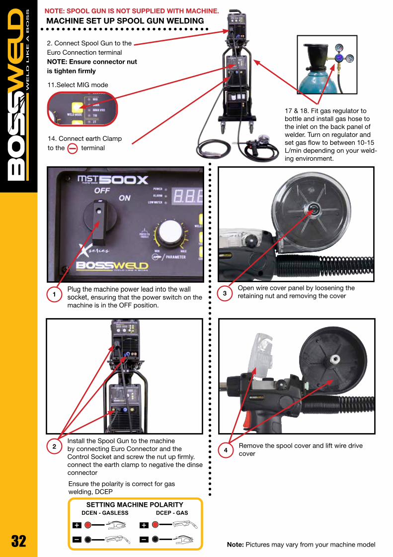
MACHINE SET UP SPOOL GUN WELDING
DCEN - GASLESS DCEP - GASSETTING MACHINE POLARITY
Open wire cover panel by loosening the retaining nut and removing the cover
Remove the spool cover and lift wire drive cover4
3Plug the machine power lead into the wall socket, ensuring that the power switch on the machine is in the OFF position.
Install the Spool Gun to the machine by connecting Euro Connector and the Control Socket and screw the nut up firmly. connect the earth clamp to negative the dinse
connector
1
2
Ensure the polarity is correct for gas welding, DCEP
Note: Pictures may vary from your machine model
2. Connect Spool Gun to the Euro Connection terminal NOTE: Ensure connector nut is tighten firmly
14. Connect earth Clamp to the terminal
11.Select MIG mode
17 & 18. Fit gas regulator to bottle and install gas hose to the inlet on the back panel of welder. Turn on regulator and set gas flow to between 10-15 L/min depending on your weld-ing environment.
NOTE: SPOOL GUN IS NOT SUPPLIED WITH MACHINE.

33
MACHINE SET UP SPOOL GUN WELDING CONTINUED
Release the wire tensioning arm, and check the correct drive roller size matches the wire being used
Replace the spool cover and close the wire drive cover5
6
7 Re-latch the tensioning arm, making sure you still hold the spool to stop it unraveling. Screw in to increase tension.
Feed the wire over the drive roller and into the inlet guide, make sure you hold the spool to stop it unraveling.
8
Note: Pictures may vary from your machine model
9
10
Turn the spool gun switch inside the SWF to ON
Switch the machine on using the mains power switch. Wait a few seconds whilst the machine powers up

34
Connect earth clamp to the work piece ensuring that the clamp makes good contact with bare metal.
11 14Press the Welding Mode Selection Button to select MIG.
Note: Pictures may vary from your machine model
12Remove nozzle and tip from torch and press trigger on the torch, this will feed the wire through the torch. Release trigger when wire appears at the end of the torch.
13Re install tip and nozzle to torch and trim wire to the end of the nozzle.
It is recommended for ease of use that the wire-feed target speed is adjusted first and then the voltage setting fine-tuned if
necessary. To adjust wire speed, turn Welding parameter Adjustment Knob.Ref MIG Welding Setting Guide on page 33-34
15
16To adjust welding voltage, turn Welding parameter Adjustment Knob. Ref MIG Weld-ing Setting Guide on page 33-34
MACHINE SET UP SPOOL GUN WELDING CONTINUED

35Note: Pictures may vary from your machine model
18
Fit gas regulator to the gas bottle and install gas hose to the gas inlet on the back panel of welder.
Turn on regulator and set gas flow to between 10-15 L/min depending on your welding environment.
17
Note: It is advisable to run a few test welds using scrap or offcut materials, in order to tune the machine to the correct settings prior to welding the job.
IMPORTANT! - We strongly recommend that you check for gas leakage prior to operation of your machine. We recommend that you close the cylinder valve when the machine is not in use. BOSSWELD authorised representatives or agents of BOSSWELD will not be liable or responsible for the loss of any gas.
MACHINE SET UP SPOOL GUN WELDING CONTINUED

36
SYNERGIC WELDING PROGRAMS
Program NumberMaterial Wire (mm) Gas
350X 500X
P1 P1 MIGMAG MANUAL
P2 P2 Solid Fe 0.8 CO2
P3 P3 Solid Fe 0.8 80%Ar+20%CO2
P4 P4 Solid Fe 0.9 CO2
P5 P5 Solid Fe 0.9 80%Ar+20%CO2
P6 P6 Solid Fe 1.0 80%Ar+20%CO2
P7 P7 Solid Fe 1.0 CO2
P8 P8 Solid Fe 1.2 CO2
P9 P9 Solid Fe 1.2 80%Ar+20%CO2
P10 Solid Fe 1.6 80%Ar+20%CO2
P11 Solid Fe 1.6 CO2
P10 P12 Flux.c.w Fe 1.0 CO2
P11 P13 Flux.c.w Fe 1.0 CO2
P12 P14 Flux.c.w Fe 1.2 CO2
P15 Flux.c.w Fe 1.6 CO2
P13 P16 SS ER316 0.9 98%Ar+2%CO2
P14 P17 SS ER316 1.0 98%Ar+2%CO2
P15 P18 SS ER316 1.2 98%Ar+2%CO2
P19 SS ER316 1.6 98%Ar+2%CO2
P16 P20 Al Mg 1.0 Ar100%
P17 P21 Al Mg 1.2 Ar100%
P22 Al Mg 1.6 Ar100%
P18 P23 Cu Si 1.0 Ar100%
P24 Flux.c.w Fe 2.0
Toggle until P is selected, then scroll through programs to select desired settings

37
BASIC MIG WELDING GUIDE
The welding power supply has two control settings that have to balance. These are voltage control switches and the wire speed control. The welding amperage is determined by the voltage settings, the wire diameter, gas selection and the wire feed speed. The amperage will increase with higher voltage selection on the machine and higher wire feed speed. This is typically used for welding thick sections of steel. When welding thin sections of steel, a lower voltage selection and lower wire feed speed is required. • When changing to a different wire diameter different control settings are required. A thinner wire needs more wire speed to achieve the same current level. • A satisfactory weld cannot be obtained if the wire speed and voltage switch settings are not adjusted to suit the wire diameter and thickness of the material being welded. • If the wire speed is too high for the welding voltage, “stubbing” will occur as the wire dips into the mol-ten pool. If the wire speed is too slow for the welding voltage, large drops will form on the end of the electrode wire, causing spatter. Suppose that wire speed is constant, if the welding voltage is too high, large drops will form on the end of the electrode wire, causing spatter; if the voltage is too low, the wire will not melt.
POSITION OF MIG GUNThe angle of MIG gun to the weld has an effect on the width of the weld run.
Distance from the MIG Gun Nozzle to the Work Piece The electrode stick out from the MIG gun nozzle should be between 2.0mm to 5.0mm when welding with gas shielded wire. An increased distance of 5mm to 10mm is required when welding with Gasless wire. This distance will vary depending on the type of joint that is being weld. .
Travel Speed Speed at which a weld travels influences the width of the weld and penetration of the welding run. Welding thin steel will have a faster travel speed than welding thick steel.
Wire Size Selection The choice of wire size in conjunction with shielding gas used depends on: • Thickness of the metal to be welded. • Type of joint configuration• Capacity of the wire feed unit and power supply. • The amount of penetration required. • The deposition rate required. • The bead profile desired • The position of welding and cost of the wire. • Location of welding
10˚ 10˚Push Drag
Wire Directionahead of bead
Push Technique Gun Perpendicular Drag (Pull) Technique
Wire Directionahead of bead
Perpendicular
Direction Of Welding

38
14
Welding Wire Selection Guide
Carbon Steel
Mig Wire, Gas Shielded Gasless, Flux Core Wire
0.6mm 0.8mm 0.9mm 1.2mm 0.8mm 0.9mm 1.2mm 0.8 30-45 1.0 45-60 50-60 1.2 60-75 70-80 50-65 1.6 70-105 90-110 90-110 70-90 75-90 2.0 120-130 120-130 90-105 95-120 3.0 135-150 135-150 110-135 120-135 4.0 145-160 160-190 135-150 135-160 135-160 6.0 175-210 190-220 145-165 150-170 8.0 215-230 225-235 150-175 160-190
10.0 220-240 230-250 200-230 12.0 240+ 250+ 240+ Gas Argon/Co2 - Co2 NO GAS
Stainless Steel Aluminium
Mig Wire, Gas Shielded Mig Wire, Gas Shielded
0.8mm 0.9mm 1.2mm 0.8mm 0.9mm 1.0mm 1.2mm 0.8 1.0 40-50 1.2 50-60 50-70 1.6 65-80 75-95 90-110 2.0 75-90 85-105 90-115 3.0 95-120 125-135 110-130 110-135 120-140 4.0 140-155 145-155 135-150 140-160 145-170 6.0 175-190 150-175 155-180 165-190 8.0 200-210 220-250 185-220 190-230
10.0 220-240 240-265 220-250 12.0 235+ 250+ 250+ Gas Argon/o2 - Argon/Co2 Argon
Note:
1. The above amperage range is to be used as a guide only
2. Welding travel speed will affect the end weld result
3. For additional information on gas selection, consult your distributor
WELDING WIRE SELECTION GUIDE
MA
TE
RIA
L T
HIC
KN
ES
SM
AT
ER
IAL
TH
ICK
NE
SS

39
Welding current Welding Volt Wave control Wire Speed
(Wire Size) 0.6mm 0.8mm 1.0mm
40A 13~15V 1-2 2--3
60A 14~16V 2-4 3--5 2--3
80A 15~17V 3-5 6--8 3--5 2--3
100A 16~19V 3-5 8--10 3--6 3-5
120A 17~20V 4-6 4--7 3--5
140A 19~21V 5-10 5--8 3--5
160A 20~22V 5-10 6--9 4--7
180A 21~23V 5-10 6--9
GMAW (MIG) WELDING
MIG welding is a versatile technique suitable for both thin sheet and thick section components. The wire is fed through a copper contact tube (contact tip) which conducts welding current into the wire. The weld pool is protected from the surrounding atmosphere by a shielding gas fed through a nozzle surrounding the wire. Shielding gas selection depends on the material being welded and the application. The wire is continuously fed from a reel by a motor drive, and the welder moves the welding torch along the joint line.
In manual MIG welding, the wire feed rate and arc length are controlled by the power source but the travel speed and wire position are under manual control. When no manual intervention is needed during welding, the process can be referred to as automatic. The process usually operates with the wire positively charged and connected to a power source delivering a constant voltage. Selection of wire diameter and wire feed speed determine the welding current, as the burn-off rate of the wire will form an equilibrium with the feed speed.
SHIELDING GAS In addition to general shielding of the arc and the weld pool, the shielding gas also:• forms the arc plasma & stabilises the arc roots on the material surface• ensures smooth transfer of molten droplets from the wire to the weld pool The shielding gas will have a substantial effect on the stability of the arc and metal transfer and the behaviour of the weld pool, in particular, its penetration.Argon based gases are generally more tolerant to parameter settings and generate lower spatter levels with the dip transfer mode. However, there is a greater risk of lack of fusion defects because these gases are colder. As CO2 cannot be used in the open arc (pulsed or spray transfer) modes due to high back-plasma forces, argon based gases containing oxygen or CO2 are normally employed.
MIG WELDING SETTING GUIDES
MIG WELDING ARGON Ar-CO2-O2
MILD STEEL √√
√√
√√
√√
XX√√
XX
XX
XX
XX
STAINLESS STEEL
LOW ALLOY STEEL
GALVINISED STEEL
ALUMINIUM
MMIG
WELDING GAS SELECTION CHART GUIDE

40
MACHINE SET UP STICK/MMA
3. Connect earth Clamp to the terminal
2. Connect Electrode holder to the terminal
Note: The below image shows setup for DCEP / Negative Polarity(Most Common application)
Plug the machine 415V 3 Phase input power lead into the wall socket, ensuring that the power switch on the machine is in the OFF
position.
Assemble Arc and Earth leads into the welding terminals depending on requirements of electrodes. Refer to your electrode packet
for polarity and current requirements.• DCEP/ Negative Polarity (most common application)- Earth clamp connector into the negative terminal.- Electrode holder connector into the positive terminal.•DCEN/Straight Polarity- Earth clamp connector into the Positive terminal.- Electrode holder connector into the Negative terminal.
1 2
6.Select Stick / MMA mode

41
MACHINE SET UP STICK/MMA - CONTINUED
Select MMA or MMA VRD on Welding Output Mode Switch.
Ensure the electrode/electrode holder is not near the work-piece or can earth out, turn the machine on using the mains power switch. The front displays will light up and the cooling
fan will start.
5
6
Select your required current by turning the Amperage Adjustment Knob.
Please see table on page 23 as a guide to Welding Parameters.
7
Connect earth clamp firmly to work-piece ensuring that the clamp makes good contact with bare metal.
Take electrode holder and press handle to open the tong. Insert bare metal rod end of electrode and release handle to clamp electrode.
3
4
Note: Pictures may vary from your machine model
6.Select Stick / MMA mode

42
MANUAL METAL ARC PROCESS (MMA WELDING)
When an arc is struck between the metal rod (electrode) and the workpiece, both the rod and workpiece surface melt to form a weld pool. Simultaneous melting of the flux coating on the rod will form gas and slag which protects the weld pool from the surrounding atmosphere. The slag will solidify and cool and must be chipped off the weld bead once the weld run is complete (or before the next weld pass is deposited). The process allows only short lengths of weld to be produced before a new electrode needs to be inserted in the holder. Weld penetration is low and the quality of the weld deposit is highly dependent on the skill of the welder.
TYPES OF ELECTRODESArc stability, depth of penetration, metal deposition rate and positional capability are greatly influenced by the chemical composition of the flux coating on the electrode. There are many types of Electrodes, and these are generally matched to the base metal. For example if welding Mild Steel then select a Mild Steel (General Purpose Electrode). Electrodes are identified by a universal numbering system (AWS Type code).
Electrodes are often packed in sealed packaging to keep moisture out. However, if a pack has been opened or damaged, it is essential that the electrodes are redried according to the manufacturer’s instructions.
ARC FORCE Also called Dig and Arc Control. Gives a power source variable additional amperage during low voltage (short arc length) conditions while welding. Helps avoid “sticking” stick electrodes when a short arc length is used.
POWER SOURCEElectrodes can be operated with AC and DC power supplies. Not all DC electrodes can be operated on AC power sources; however AC electrodes may be used on either AC or DC
Base Metal Electrode Type Type
Mild Steel Mild Steel General Purpose 6013
Stainless Steel Stainless Steel 316L 316L
Dissimilar Metals Dissimilar 680 312
Cast Iron Nickel Arc 98 Ni99
High Strength Steel Low Hydrogen TC16
Amperage Selection Guide
Rod Size/ Gauge Welding Current
1.6mm 40-50 Amps
2.0mm 50-75 Amps
2.5mm 75-105 Amps
3.2mm 105-140 Amps
4.0mm 140-160 Amps
WELDING CURRENTWelding current level is determined by the size of electrode - the normal operating range and current are recommended by manufacturers. Typical operating ranges for a selection of electrode sizes are illustrated in the table. As a rule of thumb when selecting a suitable current level, an electrode will require about 40 Amps per millimetre (diameter). Therefore, the preferred current level for a 4mm diameter electrode would be 160 Amps, but the acceptable operating range is 140 to 180 Amps. It is important to match the machine to the job
Average Metal Thickness Electrode Size
1.0 - 2.0mm 2.0mm
2.0 - 5.0mm 2.6mm
5.0 - 8mm 3.2mm
8.0mm + 4.0mm
ELECTRODE SIZE SELECTIONElectrode size selection will be determined by the thickness of the section being welded. A thicker section will need a larger diameter electrode. The table below shows the maximum size of electrodes for average thicknesses of section (based on General Purpose 6013 Electrode).

43
6. Connect the Argon Gas Regulator supplied to the Gas bottle and connect the Gas Hose from the torch to the Regulator. Ensure the Gas regulator is in the off position.
MACHINE SET UP TIG WELD
8.Select TIG mode
2. Connect TIG Torch to the terminal
5. Connect earth Clamp to the terminal
IMPORTANT! - We strongly recommend that you check for gas leakage prior to operation of your machine. We recommend that you close the cylinder valve when the machine is not in use. BOSSWELD authorised representatives or agents of BOSSWELD will not be liable or responsible for the loss of any gas.
Plug the machine 415V 3 phase input power plug into the wall socket, ensuring that the power switch on the machine is in the OFF position.
1Install the TIG Torch to the machine by connecting the TIG Dinse Connector to the Negative Output Connection Socket.
2
NOTE: TIG TORCH IS NOT SUPPLIED WITH MACHINE.

44
MACHINE SET UP TIG WELD - CONTINUED
Set up the TIG torch. Place the Tungsten Electrode into the torch head and ensure back cap and collet body are screwed in firmly.
4
Connect the Argon Gas Regulator supply to the Gas bottle and connect the Gas Hose from the TIG Torch to the Regulator. Ensure the Gas regulator is in the off position.
5
Switch the machine on using the mains power switch. Wait a few seconds whilst the ma-chine powers up
6
Fit the Earth lead Dinse Plug to the positive terminal and then connect earth clamp to the work piece ensuring that the clamp
makes good contact with bare metal.
3
Note: Pictures may vary from your machine model
To adjust the Welding Current rotate the knob to the desired Amperage, on the power source.
8
Selection TIG on the power sourcett panel.7
9Turn on regulator and set gas flow to between 10-15 L/min depending on your welding environment.

45Note: Pictures may vary from your machine model
LIFT ARC START
With a small movement rotate the Gas Cup forward so that the Tungsten Electrode touch-es the work piece.
Press the button on the TIG torch Now rotate the Gas Cup in the reverse direction to lift the Tungsten electrode from the work piece to create the arc.
3
2 4
Lay the outside edge of the Gas Cup on the work piece with the Tungsten Electrode 1- 2mm from the work piece.
1

46
TIG WELDING Tungsten inert gas (TIG) welding became an overnight success in the 1940s for joining magnesium and aluminium. Using an inert gas shield instead of a slag to protect the weldpool, the process was a highly attractive replacement for gas and manual metal arc welding. TIG has played a major role in the acceptance of aluminium for high quality welding and structural applications.
PROCESS CHARACTERISTICSIn the TIG process the arc is formed between a pointed tungsten electrode and the workpiece in an inert atmosphere of argon or helium. The small intense arc provided by the pointed electrode is ideal for high quality and precision welding. Because the electrode is not consumed during welding, the welder does not have to balance the heat input from the arc as the metal is deposited from the melting electrode. When filler metal is required, it must be added separately to the weldpool.
POWER SOURCETIG must be operated with a constant current power source - either DC or AC. A constant current power source is essential to avoid excessively high currents being drawn when the electrode is short-circuited onto the workpiece surface. This could happen either deliberately during arc starting or inadvertently during welding. If, as in MIG welding, a flat characteristic power source is used, any contact with the workpiece surface would damage the electrode tip or fuse the electrode to the workpiece surface. In DC, because arc heat is distributed approximately one- third at the cathode (negative) and two-thirds at the anode (positive), the electrode is always negative polarity to prevent overheating and melting. However, the alternative power source connection of DC electrode positive polarity has the advantage in that when the cathode is on the workpiece, the surface is cleaned of oxide contamination. For this reason, AC is used when welding materials with a tenacious surface oxide film, such as aluminium.
ARC STARTINGThe welding arc can be started by scratching the surface, forming a short-circuit. It is only when the short-circuit is broken that the main welding current will flow. However, there is a risk that the electrode may stick to the surface and cause a tungsten inclusion in the weld.
TUNGSTEN PREPARATION & GRINDING
Grinding creates the greatest hazard as the exposed tungsten/thoria area is greatly increased and fine particles of potentially radioactive dust are released into the atmosphere. It is recommended that a dedicat-ed grindstone with local dust extraction is used, and a simple filter mask is worn. If the grinding wheel is not fitted with a protective viewing screen, eye protection must be worn.
TRIGGER
WELDING WIRE
FLUX COATING
ROD
ARC
CONTACT TIP
DROPLETS
SHIELDING GAS
ARC
MOLTEN WELD METAL
SHROUD
WORK PIECE WORK PIECE
WORK PIECE WORK PIECEWORK PIECE WORK PIECE
WORK PIECE WORK PIECE
STRAIGHT GROUND
CORRECT PREPERATION - STABLE ARC INCORRECT PREPERATION - STABLE ARC
RADIAL GROUND
ARC WANDER
TUNGSTEN ELECTRODE
GAS LENS
STABLE ARC
FLAT TIP POINTED TIP
GRINDING WHEELGRINDING WHEEL
FILLER WIRE
Note: Do not use wheel for other jobs or tugsten can become contaminated and cause lower weld quality

47
MIG WELDING ARGON Ar-CO2-O2
MILD STEEL √√
√√
√√
√√
XX√√
XX
XX
XX
XX
STAINLESS STEEL
LOW ALLOY STEEL
GALVINISED STEEL
ALUMINIUM
MMIG
TTIG
XX
XX
XX
XX
√√
√√
√√
√√
TIG WELDING
MILD STEEL
STAINLESS STEEL
LOW ALLOY STEEL
ALUMINIUM
ARGON Ar-CO2-O2
WELDING GAS SELECTION CHART GUIDE
TIG WELDING - CONTINUED This risk can be minimised using the ‘lift arc’ technique where the short-circuit is formed at a very low current level. The most common way of starting the TIG arc is to use HF (High Frequency). HF consists of high voltage sparks of several thousand volts which last for a few microseconds. The HF sparks will cause the electrode - workpiece gap to break down or ionise. Once an electron/ion cloud is formed, current can flow from the power source.Note: As HF generates abnormally high electromagnetic emission (EM), welders should be aware that its use can cause interference especially in electronic equipment. As EM emission can be airborne, like radio waves, or transmitted along power cables, care must be taken to avoid interference with control systems and instruments in the vicinity of welding.HF is also important in stabilising the AC arc; in AC, electrode polarity is reversed at a frequency of about 50 times per second, causing the arc to be extinguished at each polarity change. To ensure that the arc is reignited at each reversal of polarity, HF sparks are generated across the electrode/workpiece gap to coincide with the beginning of each half-cycle.
APPLICATIONSTIG is applied in all industrial sectors but is especially suitable for high quality welding. In manual welding, the relatively small arc is ideal for thin sheet material or controlled penetration (in the root run of pipe welds). Because deposition rate can be quite low (using a separate filler rod) MMA or MIG may be preferable for thicker material and for fill passes in thick-wall pipe welds.
TIG is also widely applied in mechanised systems either autogenously or with filler wire. However, several ‘off the shelf’ systems are available for orbital welding of pipes, used in the manufacture of chemical plant or boilers. The systems require no manipulative skill, but the operator must be well trained. Because the welder has less control over arc and weldpool behaviour, careful attention must be paid to edge preparation (machined rather than hand-prepared), joint fit-up and control of welding parameters.
TRIGGER
WELDING WIRE
FLUX COATING
ROD
ARC
CONTACT TIP
DROPLETS
SHIELDING GAS
ARC
MOLTEN WELD METAL
SHROUD
WORK PIECE WORK PIECE
WORK PIECE WORK PIECEWORK PIECE WORK PIECE
WORK PIECE WORK PIECE
STRAIGHT GROUND
CORRECT PREPERATION - STABLE ARC INCORRECT PREPERATION - STABLE ARC
RADIAL GROUND
ARC WANDER
TUNGSTEN ELECTRODE
GAS LENS
STABLE ARC
FLAT TIP POINTED TIP
GRINDING WHEELGRINDING WHEEL
FILLER WIRE
Note: Do not use wheel for other jobs or tugsten can become contaminated and cause lower weld quality

48
PART NO. DESCRIPTION ORIGINAL REF
92.03.36.M6S Tip holder M6 short 28mm 142.0005
92.03.36.M6L Tip holder M6 long 32mm 142.0011
92.03.36.M8S Tip holder M8 short 28mm 142.0020
92.03.36.M8L Tip holder M8 long 32mm 142.0024
PART NO. DESCRIPTION ORIGINAL REF
92.06.36 Swan neck 014.0006
PART NO. DESCRIPTION ORIGINAL REF
92.02.36.12 Adjustable tapered nozzle ø 12mm 145.0126
92.02.36.CO Adjustable conical nozzle ø 16mm 145.0078
92.02.36.CL Adjustable cylindrical nozzle ø 20mm 145.0045
M6 Standard Duty M6 Heavy Duty M8 Contact Tip
PART NO. DESCRIPTION ORIGINAL REF
92.04.BNL12 Brass swan neck liner 1.2mm (250mm) 120.0018
92.04.BNL16 Brass swan neck liner 1.6mm (250mm) 120.0041
PART NO. DESCRIPTION ORIGINAL REF
92.05.36 Gas Diffuser 014.0261
PART NO. DESCRIPTION ORIGINAL REF
92.09.HANDLE Ergonomic handle with screws N/A
92.09.BWT Trigger N/A
PART NO. DESCRIPTION ORIGINAL REF
92.01.25.06 Contact tip heavy duty 0.6mm x M6 x 8mm dia x 28mm long
140.0005
92.01.25.08 Contact tip heavy duty 0.8mm x M6 x 8mm dia x 28mm long
140.0051
92.01.25.09 Contact tip heavy duty 0.9mm x M6 x 8mm dia x 28mm long
140.0169
92.01.25.10 Contact tip heavy duty 1.0mm x M6 x 8mm dia x 28mm long
140.0242
92.01.25.12 Contact tip heavy duty 1.2mm x M6 x 8mm dia x 28mm long
140.0379
92.01.25.14 Contact tip heavy duty 1.4mm x M6 x 8mm dia x 28mm long
140.0516
92.01.25.16 Contact tip heavy duty 1.6mm x M6 x 8mm dia x 28mm long
140.0555
92.01.M6A09 Contact tip 0.9mm x M6 Al x 8mm dia x 28mm long
141.0004
92.01.M6A10 Contact tip 1.0mm x M6 Al x 8mm dia x 28mm long
141.0006
92.01.M6A12 Contact tip 1.2mm x M6 Al x 8mm dia x 28mm long
141.0072
92.01.M83008 Contact tip 0.8mm x M8 x 10mm dia x 30mm long
140.0014
92.01.M83009 Contact tip 0.9mm x M8 x 10mm dia x 30mm long
140.0214
92.01.M83010 Contact tip 1.0mm x M8 x 10mm dia x 30mm long
140.0313
92.01.M83012 Contact tip 1.2mm x M8 x 10mm dia x 30mm long
140.0442
92.01.M83014 Contact tip 1.4mm x M8 x 10mm dia x 30mm long
-
92.01.M83016 Contact tip 1.6mm x M8 x 10mm dia x 30mm long
140.0587
PART NO. DESCRIPTION ORIGINAL REF
92.04.B3 Blue steel liner 0.6 - 0.8mm 3mt 124.0011
92.04.B4 Blue steel liner 0.6 - 0.8mm 4mt 124.0012
92.04.B5 Blue steel liner 0.6 - 0.8mm 5mt 124.0015
92.04.R3 Red steel liner 0.9 - 1.2mm 3mt 124.0026
92.04.R4 Red steel liner 0.9 - 1.2mm 4mt 124.0031
92.04.R5 Red steel liner 0.9 - 1.2mm 5mt 124.0035
92.04.Y3 Yellow steel liner 1.2 - 1.6mm 3mt 124.0041
92.04.Y4 Yellow steel liner 1.2 - 1.6mm 4mt 124.0042
92.04.Y5 Yellow steel liner 1.2 - 1.6mm 5mt 124.0043
92.04.BT3 Blue teflon liner 0.6 - 0.9mm 3mt 126.0005
92.04.BT4 Blue teflon liner 0.6 - 0.9mm 4mt 126.0008
92.04.RT3 Red teflon liner 0.9 - 1.2mm 3mt 124.0011
92.04.RT4 Red teflon liner 0.9 - 1.2mm 4mt 124.0012
92.04.RT5 Red teflon liner 0.9 - 1.2mm 5mt 124.0015
92.04.YT3 Yellow teflon liner 1.2 - 1.6mm 3mt 126.0039
92.04.YT4 Yellow teflon liner 1.2 - 1.6mm 4mt 126.0042
Steel Liners Teflon Liners for Aluminium
12 CLCO
BZ36 BOSSWELD BINZEL STYLE MIG TORCH SPARE PARTS

49
PART NO. DESCRIPTION ORIGINAL REF
92.03.501.M8S Tip Holder N/A
PART NO. DESCRIPTION ORIGINAL REF
92.06.501 Swan neck N/A
PART NO. DESCRIPTION ORIGINAL REF
92.02.501.14 Adjustable tapered nozzle ø 14mm N/A
92.02.501.CO Adjustable conical nozzle ø 16mm N/A
92.02.501.CL Adjustable cylindrical nozzle ø 20mm N/A
M8 Contact Tip
PART NO. DESCRIPTION ORIGINAL REF
92.04.BNL12 Brass swan neck liner 1.2mm (250mm) 120.0018
92.04.BNL16 Brass swan neck liner 1.6mm (250mm) 120.0041
PART NO. DESCRIPTION ORIGINAL REF
92.09.HANDLE Ergonomic handle with screws N/A
92.09.BWT Trigger N/A
PART NO. DESCRIPTION ORIGINAL REF
92.01.M83008 Contact tip 0.8mm x M8 x 10mm dia x 30mm long
140.0014
92.01.M83009 Contact tip 0.9mm x M8 x 10mm dia x 30mm long
140.0214
92.01.M83010 Contact tip 1.0mm x M8 x 10mm dia x 30mm long
140.0313
92.01.M83012 Contact tip 1.2mm x M8 x 10mm dia x 30mm long
140.0442
92.01.M83014 Contact tip 1.4mm x M8 x 10mm dia x 30mm long
-
92.01.M83016 Contact tip 1.6mm x M8 x 10mm dia x 30mm long
140.0587
PART NO. DESCRIPTION ORIGINAL REF
92.04.B3 Blue steel liner 0.6 - 0.8mm 3mt 124.0011
92.04.B4 Blue steel liner 0.6 - 0.8mm 4mt 124.0012
92.04.B5 Blue steel liner 0.6 - 0.8mm 5mt 124.0015
92.04.R3 Red steel liner 0.9 - 1.2mm 3mt 124.0026
92.04.R4 Red steel liner 0.9 - 1.2mm 4mt 124.0031
92.04.R5 Red steel liner 0.9 - 1.2mm 5mt 124.0035
92.04.Y3 Yellow steel liner 1.2 - 1.6mm 3mt 124.0041
92.04.Y4 Yellow steel liner 1.2 - 1.6mm 4mt 124.0042
92.04.Y5 Yellow steel liner 1.2 - 1.6mm 5mt 124.0043
92.04.BT3 Blue teflon liner 0.6 - 0.9mm 3mt 126.0005
92.04.BT4 Blue teflon liner 0.6 - 0.9mm 4mt 126.0008
92.04.RT3 Red teflon liner 0.9 - 1.2mm 3mt 124.0011
92.04.RT4 Red teflon liner 0.9 - 1.2mm 4mt 124.0012
92.04.RT5 Red teflon liner 0.9 - 1.2mm 5mt 124.0015
92.04.YT3 Yellow teflon liner 1.2 - 1.6mm 3mt 126.0039
92.04.YT4 Yellow teflon liner 1.2 - 1.6mm 4mt 126.0042
Steel Liners Teflon Liners for Aluminium
PART NO. DESCRIPTION ORIGINAL REF
92.05.501.GD Gas Diffuser N/A
14 CL CO
BZ501 WATER COOLED BOSSWELD BINZEL STYLE MIG TORCH SPARE PARTS

50
BACK CAP
INSULATOR
COLLET
COLLET BODY
GAS LENS ALUMINA CUPALUMINA CUP
TORCH BODY
GAS LENS COLLET BODY
PART NO. DESCRIPTION
95.26F.4.1.SW9A TIG Torch 26, 4mt, Switch, Dinse 50
95.26F.8.1.SW9A TIG Torch 26, 8mt, Switch, Dinse 50
BOSSWELD 26 SERIES 200AMP TIG TORCH COMPLETE & SPARES
PART NO. DESCRIPTION
9557Y04 Back Cap Short
9557Y05 Back Cap Medium
9557Y02 Back Cap Long
PART NO. DESCRIPTION
9518CG Torch Body Front Insulator
9554N01 Torch Body Front Insulator Lens Cup
PART NO. DESCRIPTION
9510N21 Collet 0.5mm
9510N22 Collet 1.0mm
9510N23 Collet 1.6mm
9510N24 Collet 2.4mm
9510N25 Collet 3.2mm
9510N20 Collet 4.0mm
PART NO. DESCRIPTION
9510N29 Collet Body 0.5mm
9510N30 Collet Body 1.0mm
9510N31 Collet Body 1.6mm
9510N32 Collet Body 2.4mm
9510N28 Collet Body 3.2mm
95406488 Collet Body 4.0mm
PART NO. DESCRIPTION
9510N50 Alumin Cup Size 4
9510N49 Alumin Cup Size 5
9510N48 Alumin Cup Size 6
9510N47 Alumin Cup Size 7
9510N46 Alumin Cup Size 8
9510N45 Alumin Cup Size 10
9510N44 Alumin Cup Size 12
PART NO. DESCRIPTION
9545V24 Gas Lens Collet 1.0mm
9545V25 Gas Lens Collet 1.6mm
9545V26 Gas Lens Collet 2.4mm
9545V27 Gas Lens Collet 3.2mm
9545V28 Gas Lens Collet 4.0mm
PART NO. DESCRIPTION
9554N18 Gas Len Alumin Cup Size 4 - 6.0mm
9554N17 Gas Len Alumin Cup Size 5 - 8.0mm
9554N16 Gas Len Alumin Cup Size 6 - 9.5mm
9554N15 Gas Len Alumin Cup Size 7 - 11.0mm
9554N14 Gas Len Alumin Cup Size 8 - 12.7mm
9554N19 Gas Len Alumin Cup Size 11 - 17.5mm
PART NO. DESCRIPTION
95WP26 Torch Head
954WP26V Torch Head with Valve
95WP26F Flex Torch Head
95WP26FV Flex Torch Head with Valve

51
Filler MetalSolid Mild Steel wire
Gasless Flux cored MildSteel Wire(Known as GS)
Drive Feed Roller Selection
Solid mild steelStainless steel wire
Flux cored wire
Aluminium wire
Polarity
Wire Type -Gas shield wire (solid or CO2 shielded flux)
Self-shieldedFlux core Wire
Aluminium
Notes• Use Industry standard - copper coated ER70S-6 Steel MIG Wire. This requires a shielding gas (CO2 or argon/CO2 mix),excel-lent results on panel steel.
• Use Industry standard flux cored ER71T-GS Steel MIG Wire. This does not require a shielding gas. • Suitable for outside use where gas shield can be blown away or not available. • Suitable for seldom use or when bottle hire is not practical or too costly for small jobs and infrequent use.• Great on galvanised materials• Not suitable for panel steel• Leaves chalky residue. This is normal.• Produces smoke and splatters.
It is important that correct drive roller is used to get the best results. “V” groove Roller. Roller has a small V shaped groove to guide the wire. “V Knurled” roller (assists in gripping as wire is soft)
“U” groove Roller (assist in gripping as wire is softest)
Machine can be used in both DC + and DC - modes
“-” earth
“+” earth
3m only for push torch, Teflon liner, “U” groove roller, alloy tips or one size larger, argon shielding wire
HELPFUL INFORMATION

52
Issue Power indicator is not lit, fan does not work and no output current
Power indicator is lit, fan works, no output current
Over temperature indicator is on, no output current
Output current is not stable.
Hot Welding Clamp
Excessive Spatter
Porosity - small cavities or holes resulting from gas pockets in weld metal
Possible Reason • Welder is not plugged into
power supply• Circuit breaker may have
operated• Main power switch may not
be in the ON position
• Output connectors may be disconnected or damaged
• Welding cables or earth clamp not connected prop-erly
• Duty cycle of the unit has been exceeded. .
• Earth clamp connection loose
• Mains Voltage is not constant• Loose welding cables
• Leads reversed
Welding clamp rated current is too small,
• Wire feed speed set too high• Voltage too high• Wrong polarity set
• Stick out too long• Contaminated base metal
Contaminated MIG wire
• Inadequate gas flow or too much gas flow
• Worn contact tip
• Wrong gas• Inadequate gas flow or too
much gas flow
• Moisture on the base metal
• Contaminated base metal
• Contaminated MIG wire
• Loose gas connection
Suggested Remedy • Check that the welder is plugged into the
240V mains outlet and is switched on.• Check that the mains fuse or breaker has not
operated.• Check that the main switch on the rear of the
unit is in the on position.
• Check output connectors are connected properly and are not damaged
• Check connections and that workpiece is free of paint and rust at connection point
• Allow the unit to cool for 20 minutes
• Check earth clamp is connected to work piece properly.
• Change the Main Supply to an alternative• Check the welding connectors are tight in the
sockets. • Check Leads are not reversed and correct +/_
Replace with larger size welding clamp.
• Select lower wire feed speed• Select a lower voltage setting• Select the correct polarity for the wire being
used • Bring the torch closer to the work• Remove materials like paint, grease, oil, and
dirt, including mill scale from base metal• Use clean dry rust free wire. Do not lubricate
the wire with oil, grease etc• Check the gas is connected, check hoses,
gas valve and torch are not restricted. Set the gas flow between 6-12 l/min flow rate. Check hoses and fittings for holes, leaks. Protect the welding zone from wind and drafts
• Change contact tip.
• Check that the correct gas is being used• Check the gas is connected; check hoses,
gas valve and torch are not restricted. Set the gas flow between 10 - 15 l/min flow rate. Check hoses and fittings for holes, leaks etc. Protect the welding zone from wind and drafts
• Remove all moisture from base metal before welding
• Remove materials like paint, grease, oil, and dirt, including mill scale from base metal
• Use clean dry rust free wire. Do not lubricate the wire with oil, grease etc.
Check and tighten connection.
TROUBLE SHOOTING
52

Issue Porosity - small cavities or holes resulting from gas pockets in weld metal
Wire stubbing during welding
Lack of Fusion − failure of weld metal to fuse completely with base metal or a proceeding weld bead
Excessive Penetration − weld metal melting through base meta
Lack of Penetration − shallow fusion between weld metal and base metal
Possible Reason • Gas nozzle clogged with
spatter, worn or out of shape• Missing or damaged gas
diffuser• MIG torch euro connect
O-Ring missing or damaged
• Holding the torch too far away
• Welding voltage set too low• Wire speed set too high
• Contaminated base metal
• Not enough heat input
• Improper welding technique
• Too much heat
Poor in incorrect joint preparation
• Not enough heat input
• Contaminated base metal
Suggested Remedy • Clean or replace the gas nozzle
• Replace the gas diffuser
• Check and replace the O-Ring
• Bring the torch closer to the work and maintain stick out of 5-10mm
• Increase the voltage• Decrease the wire feed speed
• Remove materials like paint, grease, oil, and dirt, including mill scale from base metal
• Select a higher voltage range and /or adjust the wire speed to suit
Keep the arc at the leading edge of the weld pool. Gun angle to work should be between 5 & 15° Direct the arc at the weld jointAdjust work angle or widen groove to access bottom during welding, Momentarily hold arc on side walls if using weaving technique• Select a lower voltage range and /or adjust
the wire speed to suit Increase travel speed
• Material too thick. Joint preparation and design needs to allow access to bottom of groove while maintaining proper welding wire extension and arc characteristics Keep the arc at the leading edge of the weld pool and maintain the gun angle at 5 & 15° keeping the stick out between 5-10mm
• Select a higher voltage range and /or adjust the wire speed to suit Reduce travel speed
• Remove materials like paint, grease, oil, and dirt, including mill scale from base metal
TROUBLE SHOOTING - CONTINUED
53

Issue No wire feed
Inconsistent / interrupted wire feed
Possible Reason • Wrong mode selected
• Adjusting wrong dial
• Wrong polarity selected
• Incorrect wire speed setting• Voltage setting incorrect• MIG torch lead too long
• MIG torch lead kinked or too sharp angle being held
• Contact tip worn, wrong size, wrong type
• Liner worn or clogged (the most common causes of bad feeding)
• Wrong size liner• Blocked or worn inlet guide
tube• Wire misaligned in drive roller
groove• Incorrect drive roller size
• Wrong type of drive roller selected
• Worn drive rollers• Drive roller pressure too high
• Too much tension on wire spool hub
• Wire crossed over on the spool or tangled
• Contaminated MIG wire
Suggested Remedy • Check that the TIG/MMA/MIG selector switch
set to MIG position
• Be sure to adjust the wire feed and voltage dials for MIG welding. The amperage dial is for MMA and TIG welding mode.
• Select the correct polarity for the wire being used - see machine set up.
• Adjust the wire feed speed• Adjust the voltage settingSmall diameter wires and soft wires like aluminium don’t feed well through long torch leads - replace the torch with a lesser length torch.• Remove the kink, reduce the angle or bend
• Replace the tip with correct size and type
• Try to clear the liner by blowing out with compressed air as a temporary cure, it is recommended to replace the liner.
• Install the correct size liner• Clear or replace the inlet guide tube
• Locate the wire into the groove of the drive roller
• Fit the correct size drive roller e.g.0.8mm wire requires 0.8mm drive roller.
• Fit the correct type roller (e.g. knurled rollers needed for flux cored wires).
• Replace the drive rollersCan flatten the wire electrode causing it to lodge in the contact tip - reduce the drive roller pressure.• Reduce the spool hub brake tension
• Remove the spool untangle the wire or replace the wire.
• Use clean dry rust free wire. Do not lubricate the wire with oil, grease etc.
MIG WIRE FEED TROUBLE SHOOTING
The following chart addresses some of the common WIRE FEED problems during MIG welding.
OPERATIONAL ENVIRONMENT
• Height above sea level ≤1000m• Operation temperature range -10°C ~ +40°C• Air relative humidity is below 90%( 20°C)• Preferably sit the machine above floor level, ensure the maximum angle does not exceed 15 degrees.• Protect the machine against heavy rain and against direct sunshine. • The content of dust, acid, corrosive gas in the surrounding air or substance must not exceed normal standards. • Take care that there is sufficient ventilation during welding. There must be at least 30cm free distance between the machine and wall.54

55

OTHER PRODUCTS IN OUR RANGE• ELECTRODES
• TIG RODS
• WELDING HELMETS
• WELDING MACHINES
• TORCH SPARE PARTS
• WELDING ACCESSORIES
• MIG WIRE
• GAS EQUIPMENT
• WELDING SAFETY
• MIG TORCHES
• TIG TORCHES
• WELDING CABLE