SIXTH DAY OF BATTLE OF AISNE FINDS ARIES STILL LOCKED IN ...
1194 IEEE TRANSACTIONS ON INDUSTRIAL ELECTRONICS, VOL. 58, NO. 4, APRIL 2011
Multiple-Complex Coefficient-Filter-BasedPhase-Locked Loop and Synchronization Technique
for Three-Phase Grid-Interfaced Convertersin Distributed Utility Networks
Xiaoqiang Guo, Weiyang Wu, Member, IEEE, and Zhe Chen, Senior Member, IEEE
Abstract—Synchronization with the utility networks is crucialfor operating three-phase grid-interfaced converters. A challengeof synchronization is how to fast and precisely extract the funda-mental positive and negative sequences under the distorted andunbalanced conditions. Many phase-locked loop (PLL) and syn-chronization techniques have been presented in the past decades.Most of them make a tradeoff between the accuracy and dy-namic response under severe distorted and unbalanced conditions.In this paper, a multiple-complex coefficient-filter-based PLL ispresented, and its unique feature lies in the accurate and rapidextraction of the positive and negative sequence components fromthe polluted grid voltage, and the harmonic components can alsobe estimated precisely, which has the potential use for selectivecompensation in active filter applications. Another advantage ofthe proposed method is its flexibility for simplifying its structurein some specified conditions. Results of continuous-domain simu-lations in MATLAB and discrete-domain experiments based on a32-b fixed-point TMS320F2812 DSP are in good agreement, whichconfirm the effectiveness of the proposed method.
Index Terms—Multiple complex-coefficient filters (MCCFs),phase-locked loop (PLL), synchronization, three-phase grid-inter-faced converters.
I. INTRODUCTION
PHASE-LOCKED loop (PLL) techniques have a long his-tory in industrial applications. The basic PLL concept was
originally published by Appleton in 1923 and Bellescize in1932, which was mainly used for synchronous reception ofradio signals. After that, PLL techniques were widely used invarious industrial fields such as communication systems, motorcontrol systems, induction heating power supplies, contactlesspower supplies, and uninterruptible power supplies. Recently,PLL techniques have been used for synchronization betweengrid-interfaced converters and the utility networks [1].
Manuscript received July 31, 2009; revised September 27, 2009 andNovember 1, 2009; accepted December 11, 2009. Date of publicationFebruary 8, 2010; date of current version March 11, 2011. This work wassupported by the National Natural Science Foundation of China under Awards50837003 and 50977081.
X. Guo and W. Wu are with the Key Lab of Power Electronics for EnergyConservation and Motor Drive of Hebei Province, Department of Electri-cal Engineering, Yanshan University, Qinhuangdao 066004, China (e-mail:[email protected]; [email protected]).
Z. Chen is with the Institute of Energy Technology, Aalborg University,Aalborg DK-9220, Denmark (e-mail: [email protected]).
Color versions of one or more of the figures in this paper are available onlineat http://ieeexplore.ieee.org.
Digital Object Identifier 10.1109/TIE.2010.2041738
Generally speaking, for single-phase applications, an idealPLL should provide the fast and accurate synchronization in-formation with a high degree of immunity and insensitivity todisturbances, harmonics, sags/swells, notches, and other typesof distortions that exist in the input signal [2]. For three-phaseapplications, however, there are further requirements such asthe sequence information [3]. For example, the grid code spec-ifications in many countries now require that the distributedgeneration systems such as wind turbines remain connectedwith the grid and have the capability of controlling the activeand reactive power flow during grid faults [4], [5]. Theserequirements are highly dependent on the control strategy ofgrid-interfaced converters. Fast and accurate extraction of thefundamental positive and negative sequence information at thepoint of common coupling (PCC) of the grid is a necessity forthe abovementioned control strategy [6], which can make rapidadjustments to the grid-interfaced converters, so the effect ofany transients can be mitigated and ride through the distur-bances during grid faults can be performed. Moreover, the se-quence information is also essential for flexible control of activerectifiers and active power filters under the unbalanced or/anddistorted grid voltage conditions [7], [8], islanding detection[9], [10], and fault monitoring [11].
In the past few years, various PLL techniques have been de-veloped for three-phase system applications. The most widelyused one is the synchronous rotating frame PLL (SRF PLL)[12], [13]. Under ideal grid conditions without any harmonicdistortion or unbalance, SRF PLL with a high bandwidth canyield a fast and precise detection of the phase and amplitude ofthe grid voltage. In case the grid voltage is distorted with high-order harmonics, the SRF PLL can still work if its bandwidthis reduced to reject and cancel out the effect of the harmonicsat the cost of the PLL response speed reduction. However, thePLL bandwidth reduction may not be an acceptable solutionin the presence of the unbalanced grid voltage. In order tosolve this problem, several modified PLLs have been presented,most of which filter the harmonics and extract the fundamentalpositive sequence which is then sent to the SRF PLL. In 2002,Yuan et al. presented a positive sequence filter to extract thefundamental positive sequence component from the distortedand unbalanced PCC voltage [7]. Later, the sinusoidal sig-nal integrator [14], double second-order generalized integrator(DSOGI) [15], and the fast PLL [16] based on software PLL
0278-0046/$26.00 © 2010 IEEE
GUO et al.: MCCF-BASED PLL AND SYNCHRONIZATION TECHNIQUE FOR GRID-INTERFACED CONVERTERS 1195
were presented for the similar purpose. On the other hand,Ghartemani and Iravani presented an enhanced PLL (EPLL)[17], whose core is an adaptive filter. Unlike the abovemen-tioned mechanism, it first filters the harmonics and keepsfrequency adaptive in a nonlinear way for each unit in the three-phase system, and then, the fundamental positive sequencecomponent can be directly obtained by the symmetrical com-ponent method [18]. Similar to EPLL, a powerful nonlinear ap-proach was presented by Yazdani et al. [19], which is based onan adaptive notch filter (ANF) and has a fast dynamic responsecompared to EPLL [20]. Another interesting approach pre-sented by Rodriguez et al. is a decoupled double synchronousreference-frame PLL (DDSRF PLL) [21]. The positive and neg-ative sequence components can be accurately extracted by thedouble synchronous frame transformations and an innovativedecoupling network. However, all the mentioned approachesshould reduce the bandwidth under the highly distorted con-ditions to attenuate the harmonics for the accurate estimationof the sequence information, which will slow the transientresponse. In 2009, Yazdani et al. presented a multiblock-ANF-based synchronization method [22], in which the low-frequencyharmonics can be removed with the multiblock ANFs, so a fastand accurate estimation of the sequence components can beachieved by using the symmetrical component method.
This paper presents a new multiple-complex coefficient-filter(MCCF)-based synchronization technique. It has the uniquefeature that, with no need of the symmetrical componentmethod or so many complicated rotating frame transformations,the fundamental positive and negative sequence informationand other harmonic components can be accurately and rapidlyestimated under the distorted and unbalanced grid voltage con-ditions. This paper is organized as follows. Section II presentsa detailed analysis for the proposed MCCF structure and theMCCF-based PLL. Section III provides a guide for the structureselection and performance evaluation of the MCCF-based PLL.Section IV demonstrates the experimental results for the samesituations tested in simulation, and Section V presents a briefdynamic performance comparison with some typical synchro-nization methods.
II. MCCF STRUCTURE
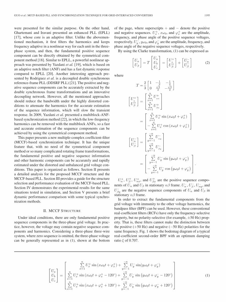
Under ideal conditions, there are only fundamental positivesequence components in the three-phase grid voltage. In prac-tice, however, the voltage may contain negative sequence com-ponents and harmonics. Considering a three-phase three-wiresystem, where zero sequence is omitted, the three-phase voltagecan be generally represented as in (1), shown at the bottom
of the page, where superscripts + and − denote the positiveand negative sequences. U+
x , xω0, and ϕ+x are the amplitude,
frequency, and phase angle of the positive sequence voltages,respectively. U−
y , yω0, and ϕ−y are the amplitude, frequency, and
phase angle of the negative sequence voltages, respectively.By using the Clarke transformation, (1) can be expressed as
[Uα
Uβ
]= T
⎡⎣Ua
Ub
Uc
⎤⎦ =
[U+
α
U+β
]+
[U−
α
U−β
](2)
where
T =23
[1 − 1
2 − 12
0√
32 −
√3
2
]
[U+
α
U+β
]=
⎡⎢⎣
n∑x=1
U+αx
n∑x=1
U+βx
⎤⎥⎦
=
⎡⎢⎣
n∑x=1
U+x sin (xω0t + ϕ+
x )
−n∑
x=1U+
x cos (xω0t + ϕ+x )
⎤⎥⎦
[U−
α
U−β
]=
⎡⎢⎢⎣
−n∑y=−1
U−αy
−n∑y=−1
U−βy
⎤⎥⎥⎦
=
⎡⎢⎢⎣
−n∑y=−1
U−y sin
(yω0t + ϕ−
y
)−
−n∑y=−1
U−y cos
(yω0t + ϕ−
y
)⎤⎥⎥⎦ .
U+α , U+
β , U+αx, and U+
βx are the positive sequence compo-nents of Uα and Uβ in stationary αβ frame. U−
α , U−β , U−
αy , andU−
βy are the negative sequence components of Uα and Uβ instationary αβ frame.
In order to extract the fundamental components from thegrid voltage with immunity to the other voltage harmonics, thebandpass filter (BPF) can be used. However, these conventionalreal-coefficient filters (RCFs) have only the frequency-selectiveproperty, but no polarity-selective (for example, ±50 Hz) prop-erty. That is, these filters cannot make the distinction betweenthe positive (+50 Hz) and negative (−50 Hz) polarities for thesame frequency. Fig. 1 shows the bodemag diagram of a typicalreal-coefficient second-order BPF with an optimum dampingratio ξ of 0.707.
⎡⎣Ua
Ub
Uc
⎤⎦ =
⎡⎢⎢⎢⎢⎢⎢⎣
n∑x=1
U+x sin (xω0t + ϕ+
x ) +−n∑
y=−1U−
y sin(yω0t + ϕ−y )
n∑x=1
U+x sin (xω0t + ϕ+
x − 120◦) +−n∑
y=−1U−
y sin(yω0t + ϕ−
y − 120◦)
n∑x=1
U+x sin (xω0t + ϕ+
x + 120◦) +−n∑
y=−1U−
y sin(yω0t + ϕ−
y + 120◦)
⎤⎥⎥⎥⎥⎥⎥⎦
(1)

1196 IEEE TRANSACTIONS ON INDUSTRIAL ELECTRONICS, VOL. 58, NO. 4, APRIL 2011
Fig. 1. Bodemag diagram of the second-order BPF.
From Fig. 1, it can be observed that the attenuation ratio atboth the fundamental positive sequence (50 Hz) and negativesequence (−50 Hz) frequencies are 1, which means that bothpositive and negative sequences will pass the BPF without anyattenuation. Thus, the positive and negative sequences cannotbe directly extracted by these filters. Moreover, the cutoff fre-quency of these filters should be reduced for better performanceat the expense of the dynamic response in the case of highlydistorted environments.
On the other hand, the complex-coefficient filter (CCF) hasthe unique feature of both frequency and polarity-selectiveproperty. In fact, CCF has been widely used in industrial appli-cations such as various communication systems [23]. However,its use for the real-time positive and negative sequence extrac-tion in grid-connected converter applications has not receivedmuch attention.
A. Basic CCF
An ideal frequency and polarity-selective CCF should notonly keep unity gain and zero phase shift at the selectedfrequency and deep attenuation at the other frequencies butalso provide fast response for the real-time signal extraction.A typical first-order CCF can be expressed in the followingequation, and the corresponding bode diagram is shown inFig. 2, where ωc and ω0 are set to 314 rad/s:
CCF (s) =ωc
s − jω0 + ωc. (3)
From (3), it can be observed that the filter can extract thespecified frequency (ω0) component with unity gain and zerophase shift. Meanwhile, at the other frequencies, the amplitudeattenuation ratio is ωc/(
√(ω − ω0)2 + ω2
c ), and the phaseshift is arctan[(ω0 − ω)/ωc]. As shown in Fig. 2, setting thespecified frequency ω0 for the positive sequence (50 Hz), thepositive sequence will be fully extracted, while the negativeone (−50 Hz) will be attenuated by ωc/(
√4ω2
0 + ω2c ) with a
phase shift of tan−1(2ω0/ωc). Moreover, the harmonics willalso be attenuated to a certain level. Compared with RCF, CCFhas the advantage of the polarity-selective property to extractthe positive or negative sequence in a straightforward manner,but it has the same features as RCF that a tradeoff between theextraction accuracy and response speed should be made if thegrid voltage is contaminated with unbalance and distortions.
Fig. 2. Bode diagram of the first-order CCF.
Fig. 3. MCCF structure.
B. MCCF Structure
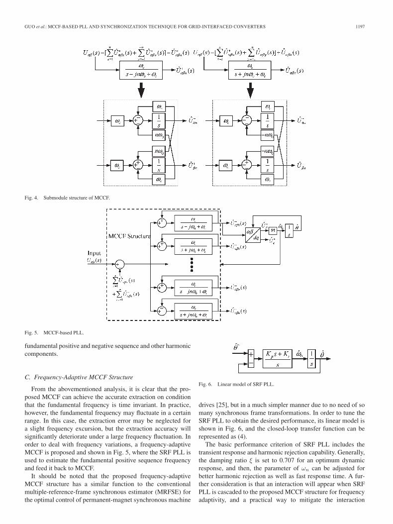
In this section, a new structure with the MCCF is proposedto achieve the accurate and rapid extraction for the specifiedsequences. Fig. 3 shows the MCCF structure, where Uαβ is theinput of MCCF and U+
αβ1(s), U−αβ1(s), . . . , U
+αβn(s), U−
αβn(s)are the estimated fundamental and harmonic sequencecomponents.
There are various methods for realizing the submodules ofMCCF. In this paper, simple direct forms [24] are used, and thecorresponding block diagram is given in Fig. 4.
The mathematical model of the proposed MCCF structurecan be found in the Appendix. From (A5), it can be observedthat the proposed MCCF structure can accurately extract the
GUO et al.: MCCF-BASED PLL AND SYNCHRONIZATION TECHNIQUE FOR GRID-INTERFACED CONVERTERS 1197
Fig. 4. Submodule structure of MCCF.
Fig. 5. MCCF-based PLL.
fundamental positive and negative sequence and other harmoniccomponents.
C. Frequency-Adaptive MCCF Structure
From the abovementioned analysis, it is clear that the pro-posed MCCF can achieve the accurate extraction on conditionthat the fundamental frequency is time invariant. In practice,however, the fundamental frequency may fluctuate in a certainrange. In this case, the extraction error may be neglected fora slight frequency excursion, but the extraction accuracy willsignificantly deteriorate under a large frequency fluctuation. Inorder to deal with frequency variations, a frequency-adaptiveMCCF is proposed and shown in Fig. 5, where the SRF PLL isused to estimate the fundamental positive sequence frequencyand feed it back to MCCF.
It should be noted that the proposed frequency-adaptiveMCCF structure has a similar function to the conventionalmultiple-reference-frame synchronous estimator (MRFSE) forthe optimal control of permanent-magnet synchronous machine
Fig. 6. Linear model of SRF PLL.
drives [25], but in a much simpler manner due to no need of somany synchronous frame transformations. In order to tune theSRF PLL to obtain the desired performance, its linear model isshown in Fig. 6, and the closed-loop transfer function can berepresented as (4).
The basic performance criterion of SRF PLL includes thetransient response and harmonic rejection capability. Generally,the damping ratio ξ is set to 0.707 for an optimum dynamicresponse, and then, the parameter of ωn can be adjusted forbetter harmonic rejection as well as fast response time. A fur-ther consideration is that an interaction will appear when SRFPLL is cascaded to the proposed MCCF structure for frequencyadaptivity, and a practical way to mitigate the interaction
1198 IEEE TRANSACTIONS ON INDUSTRIAL ELECTRONICS, VOL. 58, NO. 4, APRIL 2011
between the MCCF structure and SRF PLL is to make theestimator (MCCF) faster than the control (SRF PLL) [25].
H(s) =θ(s)
θ∗(s)=
2ξωns + ω2n
s2 + 2ξωns + ω2n
(4)
where ωn =√
Ki and ξ = (Kp/2√
Ki).
III. STRUCTURE SELECTION AND PERFORMANCE TEST
As described in the previous section, the proposed MCCFstructure has the advantages of the fast and precise specifiedcomponent extraction. Although a much simpler structure thanthe conventional MRFSE, the computational burden of theMCCF structure still seems a problem. However, it shouldbe noted that there are some unique features for three-phasegrid-connected converter applications in utility networks [26].For example, the fundamental positive sequence component isdominated in the grid voltage. The fundamental negative onemay appear in the case of three-phase voltage imbalance, and itsamplitude is relatively large during the severe grid unbalancedfaults. For the harmonic components, they may mainly consistof low-order 5th, 7th, 11th, 13th, etc., and their magnitude willtend to be lower as their frequency increases.
Therefore, considering the filtering feature of MCCF, it isrecommended that the two-module (TM) system (n = ±1) ofstructure shown in Fig. 3 can be used in case the grid voltageis unbalanced and relatively small distorted; even its frequencyfluctuates in a small range (for example, ±0. 5 Hz). If the gridfrequency experiences a larger fluctuation in the first case, theTM adaptive system of structure (n = ±1) shown in Fig. 5can be used. In this way, the computational burden can besignificantly reduced.
However, the extraction error will not be acceptable with theTM structure when the grid voltage harmonics are relativelylarge. In this case, a multiple-module (MM) structure (forexample, n = ±1,−5,+7) will be recommended for the fastand accurate extraction of each frequency component of interestat the cost of computational burden. It should be pointed outthat the speed of DSP is faster and faster with the developmentof technology, so the implementation of the proposed MCCFstructure will have no great difficulty in practice.
A. Unbalance
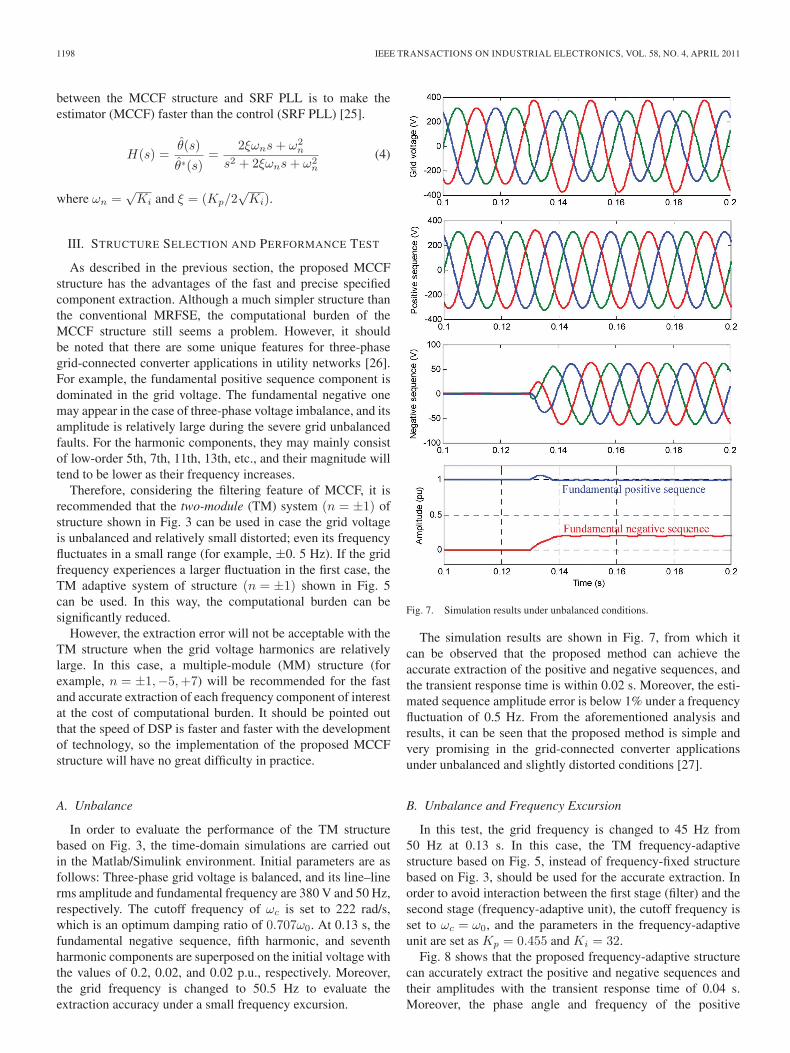
In order to evaluate the performance of the TM structurebased on Fig. 3, the time-domain simulations are carried outin the Matlab/Simulink environment. Initial parameters are asfollows: Three-phase grid voltage is balanced, and its line–linerms amplitude and fundamental frequency are 380 V and 50 Hz,respectively. The cutoff frequency of ωc is set to 222 rad/s,which is an optimum damping ratio of 0.707ω0. At 0.13 s, thefundamental negative sequence, fifth harmonic, and seventhharmonic components are superposed on the initial voltage withthe values of 0.2, 0.02, and 0.02 p.u., respectively. Moreover,the grid frequency is changed to 50.5 Hz to evaluate theextraction accuracy under a small frequency excursion.
Fig. 7. Simulation results under unbalanced conditions.
The simulation results are shown in Fig. 7, from which itcan be observed that the proposed method can achieve theaccurate extraction of the positive and negative sequences, andthe transient response time is within 0.02 s. Moreover, the esti-mated sequence amplitude error is below 1% under a frequencyfluctuation of 0.5 Hz. From the aforementioned analysis andresults, it can be seen that the proposed method is simple andvery promising in the grid-connected converter applicationsunder unbalanced and slightly distorted conditions [27].
B. Unbalance and Frequency Excursion
In this test, the grid frequency is changed to 45 Hz from50 Hz at 0.13 s. In this case, the TM frequency-adaptivestructure based on Fig. 5, instead of frequency-fixed structurebased on Fig. 3, should be used for the accurate extraction. Inorder to avoid interaction between the first stage (filter) and thesecond stage (frequency-adaptive unit), the cutoff frequency isset to ωc = ω0, and the parameters in the frequency-adaptiveunit are set as Kp = 0.455 and Ki = 32.
Fig. 8 shows that the proposed frequency-adaptive structurecan accurately extract the positive and negative sequences andtheir amplitudes with the transient response time of 0.04 s.Moreover, the phase angle and frequency of the positive

GUO et al.: MCCF-BASED PLL AND SYNCHRONIZATION TECHNIQUE FOR GRID-INTERFACED CONVERTERS 1199
Fig. 8. Simulation results under unbalanced and variable frequencyconditions.
sequence can also be estimated precisely. On the other hand,the conventional SRF PLL is sensitive to unbalance, and theestimated frequency has a 90-Hz ripple.
Fig. 9. Simulation results under distorted, unbalanced, and variable frequencyconditions.
1200 IEEE TRANSACTIONS ON INDUSTRIAL ELECTRONICS, VOL. 58, NO. 4, APRIL 2011
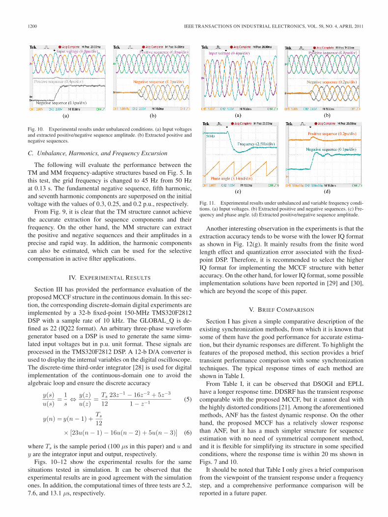
Fig. 10. Experimental results under unbalanced conditions. (a) Input voltagesand extracted positive/negative sequence amplitude. (b) Extracted positive andnegative sequences.
C. Unbalance, Harmonics, and Frequency Excursion
The following will evaluate the performance between theTM and MM frequency-adaptive structures based on Fig. 5. Inthis test, the grid frequency is changed to 45 Hz from 50 Hzat 0.13 s. The fundamental negative sequence, fifth harmonic,and seventh harmonic components are superposed on the initialvoltage with the values of 0.3, 0.25, and 0.2 p.u., respectively.
From Fig. 9, it is clear that the TM structure cannot achievethe accurate extraction for sequence components and theirfrequency. On the other hand, the MM structure can extractthe positive and negative sequences and their amplitudes in aprecise and rapid way. In addition, the harmonic componentscan also be estimated, which can be used for the selectivecompensation in active filter applications.
IV. EXPERIMENTAL RESULTS
Section III has provided the performance evaluation of theproposed MCCF structure in the continuous domain. In this sec-tion, the corresponding discrete-domain digital experiments areimplemented by a 32-b fixed-point 150-MHz TMS320F2812DSP with a sample rate of 10 kHz. The GLOBAL_Q is de-fined as 22 (IQ22 format). An arbitrary three-phase waveformgenerator based on a DSP is used to generate the same simu-lated input voltages but in p.u. unit format. These signals areprocessed in the TMS320F2812 DSP. A 12-b D/A converter isused to display the internal variables on the digital oscilloscope.The discrete-time third-order integrator [28] is used for digitalimplementation of the continuous-domain one to avoid thealgebraic loop and ensure the discrete accuracy
y(s)u(s)
=1s⇔ y(z)
u(z)=
Ts
1223z−1 − 16z−2 + 5z−3
1 − z−1(5)
y(n) = y(n − 1) +Ts
12× [23u(n − 1) − 16u(n − 2) + 5u(n − 3)] (6)
where Ts is the sample period (100 μs in this paper) and u andy are the integrator input and output, respectively.
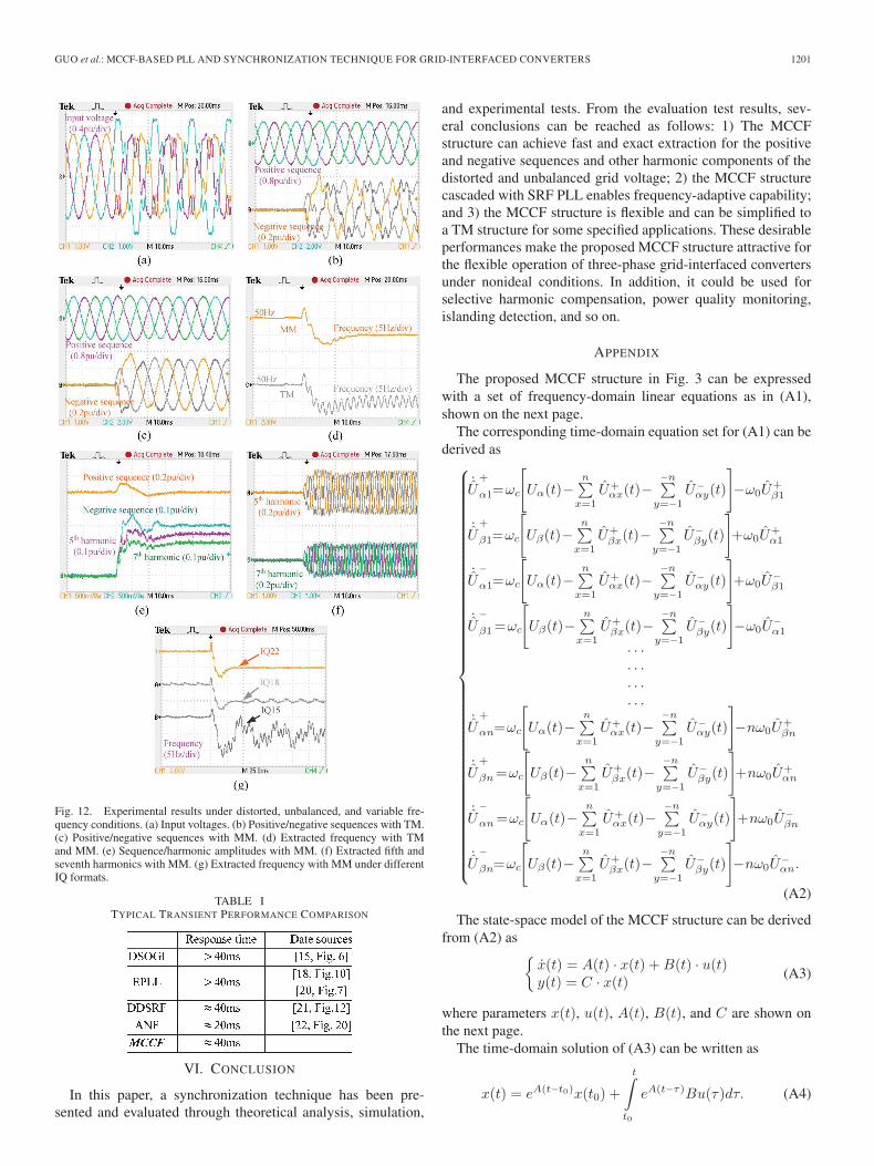
Figs. 10–12 show the experimental results for the samesituations tested in simulation. It can be observed that theexperimental results are in good agreement with the simulationones. In addition, the computational times of three tests are 5.2,7.6, and 13.1 μs, respectively.
Fig. 11. Experimental results under unbalanced and variable frequency condi-tions. (a) Input voltages. (b) Extracted positive and negative sequences. (c) Fre-quency and phase angle. (d) Extracted positive/negative sequence amplitude.
Another interesting observation in the experiments is that theextraction accuracy tends to be worse with the lower IQ formatas shown in Fig. 12(g). It mainly results from the finite wordlength effect and quantization error associated with the fixed-point DSP. Therefore, it is recommended to select the higherIQ format for implementing the MCCF structure with betteraccuracy. On the other hand, for lower IQ format, some possibleimplementation solutions have been reported in [29] and [30],which are beyond the scope of this paper.
V. BRIEF COMPARISON
Section I has given a simple comparative description of theexisting synchronization methods, from which it is known thatsome of them have the good performance for accurate estima-tion, but their dynamic responses are different. To highlight thefeatures of the proposed method, this section provides a brieftransient performance comparison with some synchronizationtechniques. The typical response times of each method areshown in Table I.
From Table I, it can be observed that DSOGI and EPLLhave a longer response time. DDSRF has the transient responsecomparable with the proposed MCCF, but it cannot deal withthe highly distorted conditions [21]. Among the aforementionedmethods, ANF has the fastest dynamic response. On the otherhand, the proposed MCCF has a relatively slower responsethan ANF, but it has a much simpler structure for sequenceestimation with no need of symmetrical component method,and it is flexible for simplifying its structure in some specifiedconditions, where the response time is within 20 ms shown inFigs. 7 and 10.
It should be noted that Table I only gives a brief comparisonfrom the viewpoint of the transient response under a frequencystep, and a comprehensive performance comparison will bereported in a future paper.
GUO et al.: MCCF-BASED PLL AND SYNCHRONIZATION TECHNIQUE FOR GRID-INTERFACED CONVERTERS 1201
Fig. 12. Experimental results under distorted, unbalanced, and variable fre-quency conditions. (a) Input voltages. (b) Positive/negative sequences with TM.(c) Positive/negative sequences with MM. (d) Extracted frequency with TMand MM. (e) Sequence/harmonic amplitudes with MM. (f) Extracted fifth andseventh harmonics with MM. (g) Extracted frequency with MM under differentIQ formats.
TABLE ITYPICAL TRANSIENT PERFORMANCE COMPARISON
VI. CONCLUSION
In this paper, a synchronization technique has been pre-sented and evaluated through theoretical analysis, simulation,
and experimental tests. From the evaluation test results, sev-eral conclusions can be reached as follows: 1) The MCCFstructure can achieve fast and exact extraction for the positiveand negative sequences and other harmonic components of thedistorted and unbalanced grid voltage; 2) the MCCF structurecascaded with SRF PLL enables frequency-adaptive capability;and 3) the MCCF structure is flexible and can be simplified toa TM structure for some specified applications. These desirableperformances make the proposed MCCF structure attractive forthe flexible operation of three-phase grid-interfaced convertersunder nonideal conditions. In addition, it could be used forselective harmonic compensation, power quality monitoring,islanding detection, and so on.
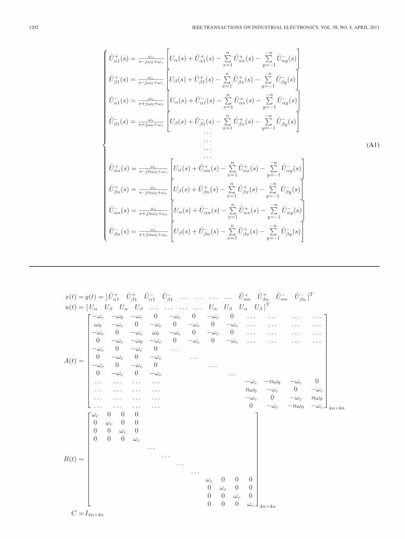
APPENDIX
The proposed MCCF structure in Fig. 3 can be expressedwith a set of frequency-domain linear equations as in (A1),shown on the next page.
The corresponding time-domain equation set for (A1) can bederived as⎧⎪⎪⎪⎪⎪⎪⎪⎪⎪⎪⎪⎪⎪⎪⎪⎪⎪⎪⎪⎪⎪⎪⎪⎪⎪⎪⎪⎪⎪⎪⎪⎪⎪⎪⎪⎪⎪⎪⎪⎪⎪⎨
⎪⎪⎪⎪⎪⎪⎪⎪⎪⎪⎪⎪⎪⎪⎪⎪⎪⎪⎪⎪⎪⎪⎪⎪⎪⎪⎪⎪⎪⎪⎪⎪⎪⎪⎪⎪⎪⎪⎪⎪⎪⎩
˙U
+
α1=ωc
[Uα(t)−
n∑x=1
U+αx(t)−
−n∑y=−1
U−αy(t)
]−ω0U
+β1
˙U
+
β1=ωc
[Uβ(t)−
n∑x=1
U+βx(t)−
−n∑y=−1
U−βy(t)
]+ω0U
+α1
˙U
−α1=ωc
[Uα(t)−
n∑x=1
U+αx(t)−
−n∑y=−1
U−αy(t)
]+ω0U
−β1
˙U
−β1 =ωc
[Uβ(t)−
n∑x=1
U+βx(t)−
−n∑y=−1
U−βy(t)
]−ω0U
−α1
. . .
. . .
. . .
. . .
˙U
+
αn=ωc
[Uα(t)−
n∑x=1
U+αx(t)−
−n∑y=−1
U−αy(t)
]−nω0U
+βn
˙U
+
βn =ωc
[Uβ(t)−
n∑x=1
U+βx(t)−
−n∑y=−1
U−βy(t)
]+nω0U
+αn
˙U
−αn =ωc
[Uα(t)−
n∑x=1
U+αx(t)−
−n∑y=−1
U−αy(t)
]+nω0U
−βn
˙U
−βn=ωc
[Uβ(t)−
n∑x=1
U+βx(t)−
−n∑y=−1
U−βy(t)
]−nω0U
−αn.
(A2)
The state-space model of the MCCF structure can be derivedfrom (A2) as {
x(t) = A(t) · x(t) + B(t) · u(t)y(t) = C · x(t) (A3)
where parameters x(t), u(t), A(t), B(t), and C are shown onthe next page.
The time-domain solution of (A3) can be written as
x(t) = eA(t−t0)x(t0) +
t∫t0
eA(t−τ)Bu(τ)dτ. (A4)
1202 IEEE TRANSACTIONS ON INDUSTRIAL ELECTRONICS, VOL. 58, NO. 4, APRIL 2011
⎧⎪⎪⎪⎪⎪⎪⎪⎪⎪⎪⎪⎪⎪⎪⎪⎪⎪⎪⎪⎪⎪⎪⎪⎪⎪⎪⎪⎪⎪⎪⎪⎪⎪⎪⎪⎪⎪⎪⎪⎪⎪⎨⎪⎪⎪⎪⎪⎪⎪⎪⎪⎪⎪⎪⎪⎪⎪⎪⎪⎪⎪⎪⎪⎪⎪⎪⎪⎪⎪⎪⎪⎪⎪⎪⎪⎪⎪⎪⎪⎪⎪⎪⎪⎩
U+α1(s) = ωc
s−jω0+ωc
[Uα(s) + U+
α1(s) −n∑
x=1U+
αx(s) −−n∑
y=−1U−
αy(s)
]
U+β1(s) = ωc
s−jω0+ωc
[Uβ(s) + U+
β1(s) −n∑
x=1U+
βx(s) −−n∑
y=−1U−
βy(s)
]
U−α1(s) = ωc
s+jω0+ωc
[Uα(s) + U−
α1(s) −n∑
x=1U+
αx(s) −−n∑
y=−1U−
αy(s)
]
U−β1(s) = ωc
s+jω0+ωc
[Uβ(s) + U−
β1(s) −n∑
x=1U+
βx(s) −−n∑
y=−1U−
βy(s)
]. . .. . .. . .. . .
U+αn(s) = ωc
s−jnω0+ωc
[Uα(s) + U+
αn(s) −n∑
x=1U+
αx(s) −−n∑
y=−1U−
αy(s)
]
U+βn(s) = ωc
s−jnω0+ωc
[Uβ(s) + U+
βn(s) −n∑
x=1U+
βx(s) −−n∑
y=−1U−
βy(s)
]
U−αn(s) = ωc
s+jnω0+ωc
[Uα(s) + U−
αn(s) −n∑
x=1U+
αx(s) −−n∑
y=−1U−
αy(s)
]
U−βn(s) = ωc
s+jnω0+ωc
[Uβ(s) + U−
βn(s) −n∑
x=1U+
βx(s) −−n∑
y=−1U−
βy(s)
]
(A1)
x(t) = y(t) = [ U+α1 U+
β1 U−α1 U−
β1 . . . . . . . . . . . . U+αn U+
βn U−αn U−
βn ]T
u(t) = [Uα Uβ Uα Uβ . . . . . . . . . . . . Uα Uβ Uα Uβ ]T
A(t) =
⎡⎢⎢⎢⎢⎢⎢⎢⎢⎢⎢⎢⎢⎢⎢⎢⎢⎢⎣
−ωc −ω0 −ωc 0 −ωc 0 −ωc 0 . . . . . . . . . . . .ω0 −ωc 0 −ωc 0 −ωc 0 −ωc . . . . . . . . . . . .−ωc 0 −ωc ω0 −ωc 0 −ωc 0 . . . . . . . . . . . .0 −ωc −ω0 −ωc 0 −ωc 0 −ωc . . . . . . . . . . . .
−ωc 0 −ωc 0 . . .0 −ωc 0 −ωc . . .
−ωc 0 −ωc 0 . . .0 −ωc 0 −ωc . . .
. . . . . . . . . . . . −ωc −nω0 −ωc 0
. . . . . . . . . . . . nω0 −ωc 0 −ωc
. . . . . . . . . . . . −ωc 0 −ωc nω0
. . . . . . . . . . . . 0 −ωc −nω0 −ωc
⎤⎥⎥⎥⎥⎥⎥⎥⎥⎥⎥⎥⎥⎥⎥⎥⎥⎥⎦
4n×4n
B(t) =
⎡⎢⎢⎢⎢⎢⎢⎢⎢⎢⎢⎢⎢⎢⎢⎢⎢⎢⎣
ωc 0 0 00 ωc 0 00 0 ωc 00 0 0 ωc
. . .. . .
. . .. . .
ωc 0 0 00 ωc 0 00 0 ωc 00 0 0 ωc
⎤⎥⎥⎥⎥⎥⎥⎥⎥⎥⎥⎥⎥⎥⎥⎥⎥⎥⎦
4n×4n
C = I4n×4n
GUO et al.: MCCF-BASED PLL AND SYNCHRONIZATION TECHNIQUE FOR GRID-INTERFACED CONVERTERS 1203
The full mathematic expression for the time-domain solutionof (A4) is too complex to describe here. However, it can beconcluded that its transient response mainly depends on thecutoff frequency of ωc. On the other hand, the steady-statesolution to (A4) is
x(t)=
⎡⎢⎢⎢⎢⎢⎢⎢⎢⎢⎢⎢⎢⎢⎢⎢⎢⎢⎢⎢⎣
U+α1
U+β1
U−α1
U−β1
. . .
. . .
. . .
. . .U+
αn
U+βn
U−αn
U−βn
⎤⎥⎥⎥⎥⎥⎥⎥⎥⎥⎥⎥⎥⎥⎥⎥⎥⎥⎥⎥⎦
=
⎡⎢⎢⎢⎢⎢⎢⎢⎢⎢⎢⎢⎢⎢⎢⎢⎢⎢⎢⎣
U+α1
U+β1
U−α1
U−β1
. . .
. . .
. . .
. . .U+
αn
U+βn
U−αn
U−βn
⎤⎥⎥⎥⎥⎥⎥⎥⎥⎥⎥⎥⎥⎥⎥⎥⎥⎥⎥⎦
=
⎡⎢⎢⎢⎢⎢⎢⎢⎢⎢⎢⎢⎢⎢⎢⎢⎢⎢⎢⎣
U+1 sin
(ω0t + ϕ+
1
)−U+
1 cos(ω0t + ϕ+
1
)U−
1 sin(−ω0t + ϕ−
1
)−U−
1 cos(−ω0t + ϕ−
1
). . .. . .. . .. . .
U+n sin (nω0t + ϕ+
n )−U+
n cos (nω0t + ϕ+n )
U−n sin (−nω0t + ϕ−
n)−U−
n cos (−nω0t + ϕ−n)
⎤⎥⎥⎥⎥⎥⎥⎥⎥⎥⎥⎥⎥⎥⎥⎥⎥⎥⎥⎦
4n×1
.
(A5)
REFERENCES
[1] F. Blaabjerg, R. Teodorescu, M. Liserre, and A. V. Timbus, “Overviewof control and grid synchronization for distributed power generationsystems,” IEEE Trans. Ind. Electron., vol. 53, no. 5, pp. 1398–1409,Oct. 2006.
[2] R. M. Santos Filho, P. F. Seixas, P. C. Cortizo, L. A. B. Torres, andA. F. Souza, “Comparison of three single-phase PLL algorithms for UPSapplications,” IEEE Trans. Ind. Electron., vol. 55, no. 8, pp. 2923–2932,Aug. 2008.
[3] H. E. P. de Souza, F. Bradaschia, F. A. S. Neves, M. C. Cavalcanti,G. M. S. Azevedo, and J. P. de Arruda, “A method for extracting thefundamental-frequency positive-sequence voltage vector based on simplemathematical transformations,” IEEE Trans. Ind. Electron., vol. 56, no. 5,pp. 1539–1547, May 2009.
[4] Z. Chen, J. M. Guerrero, and F. Blaabjerg, “A review of the state of theart of power electronics for wind turbines,” IEEE Trans. Power Electron.,vol. 24, no. 8, pp. 1859–1875, Aug. 2009.
[5] S. Alepuz, S. Busquets-Monge, J. Bordonau, J. A. Martínez-Velasco,C. A. Silva, J. Pontt, and J. Rodríguez, “Control strategies based on sym-metrical components for grid-connected converters under voltage dips,”in IEEE Trans. Ind. Electron., Jun. 2009, vol. 56, no. 6, pp. 2162–2173.
[6] P. Rodriguez, A. Luna, R. Teodorescu, and F. Blaabjerg, “Grid synchro-nization of wind turbine converters under transient grid faults using adouble synchronous reference frame PLL,” in Proc. IEEE Energy 2030Conf., 2008, pp. 1–8.
[7] X. Yuan, J. Allmeling, W. Merk, and H. Stemmler, “Stationary-framegeneralized integrators for current control of active power filters with zerosteady state error for current harmonics of concern under unbalanced anddistorted operation conditions,” IEEE Trans. Ind. Appl., vol. 38, no. 2,pp. 523–532, Mar./Apr. 2002.
[8] H. S. Song and K. Nam, “Dual current control scheme for PWM converterunder unbalanced input voltage conditions,” IEEE Trans. Ind. Electron.,vol. 46, no. 5, pp. 953–959, Oct. 1999.
[9] S.-I. Jang and K.-H. Kim, “An islanding detection method for distributedgenerations using voltage unbalance and total harmonic distortion of cur-rent,” IEEE Trans. Power Del., vol. 19, no. 2, pp. 745–752, Apr. 2004.
[10] H. Karimi, A. Yazdani, and R. Iravani, “Negative-sequence current in-jection for fast islanding detection of a distributed resource unit,” IEEETrans. Power Electron., vol. 23, no. 1, pp. 298–307, Jan. 2008.
[11] L. Wu, X. Huang, T. G. Habetler, and R. G. Harley, “Eliminating loadoscillation effects for rotor eccentricity detection in closed-loop drive-connected induction motors,” IEEE Trans. Power Electron., vol. 22, no. 4,pp. 1543–1551, Jul. 2007.
[12] V. Kaura and V. Blasko, “Operation of a phase locked loop system underdistorted utility conditions,” IEEE Trans. Ind. Appl., vol. 33, no. 1, pp. 58–63, Jan./Feb. 1997.
[13] S.-K. Chung, “A phase tracking system for three phase utility interfaceinverters,” IEEE Trans. Power Electron., vol. 15, no. 3, pp. 431–438,May 2000.
[14] R. I. Bojoi, G. Griva, V. Bostan, M. Guerriero, F. Farina, and F. Profumo,“Current control strategy for power conditioners using sinusoidal signalintegrators in synchronous reference frame,” IEEE Trans. Power Elec-tron., vol. 20, no. 6, pp. 1402–1412, Nov. 2005.
[15] P. Rodriguez, R. Teodorescu, I. Candela, A. V. Timbus, M. Liserre, andF. Blaabjerg, “New positive-sequence voltage detector for grid synchro-nization of power converters under faulty grid conditions,” in Proc. IEEEPESC, 2006, pp. 1–7.
[16] M. Wei and Z. Chen, “A fast PLL method for power electronicsystems connected to distorted grids,” in Proc. IEEE IECON, 2007,pp. 1702–1707.
[17] M. K. Ghartemani and M. R. Iravani, “A nonlinear adaptive filter foronline signal analysis in power systems applications,” IEEE Trans. PowerDel., vol. 17, no. 2, pp. 617–622, Apr. 2002.
[18] M. K. Ghartemani and M. R. Iravani, “A method for synchronizationof power electronic converters in polluted and variable-frequency en-vironments,” IEEE Trans. Power Syst., vol. 19, no. 3, pp. 1263–1270,Aug. 2004.
[19] D. Yazdani, A. Bakhshai, G. Joos, and M. Mojiri, “A nonlinear adaptivesynchronization technique for grid-connected distributed energy,” IEEETrans. Power Electron., vol. 23, no. 4, pp. 2181–2186, Jul. 2008.
[20] D. Yazdani, A. Bakhshai, G. Joos, and M. Mojiri, “A nonlinear adaptivesynchronization technique for single-phase grid-connected converters,” inProc. IEEE PESC, 2008, pp. 4076–4079.
[21] P. Rodriguez, J. Pou, J. Bergas, J. I. Candela, R. P. Burgos, andD. Boroyevich, “Decoupled double synchronous reference frame PLL forpower converters control,” IEEE Trans. Power Electron., vol. 22, no. 2,pp. 584–592, Mar. 2007.
[22] D. Yazdani, M. Mojiri, A. Bakhshai, and G. Joos, “A fast and accuratesynchronization technique for extraction of symmetrical components,”IEEE Trans. Power Electron., vol. 24, no. 3, pp. 674–684, Mar. 2009.
[23] K. W. Martin, “Complex signal processing is not complex,” IEEE Trans.Circuits Syst. I, Reg. Papers, vol. 51, no. 9, pp. 1823–1836, Sep. 2004.
[24] J. Kauraniemi, T. I. Laakso, I. Hartimo, and S. J. Ovaska, “Delta opera-tor realizations of direct-form IIR filters,” IEEE Trans. Circuits Syst. II,Analog Digit. Signal Process., vol. 45, no. 1, pp. 41–52, Jan. 1998.
[25] P. L. Chapman and S. D. Sudhoff, “A multiple reference frame synchro-nous estimator/regulator,” IEEE Trans. Energy Convers., vol. 15, no. 2,pp. 197–202, Jun. 2000.
[26] P. Xiao, K. A. Corzine, and G. K. Venayagamoorthy, “Multiple ref-erence frame-based control of three-phase PWM boost rectifiers underunbalanced and distorted input conditions,” IEEE Trans. Power Electron.,vol. 23, no. 4, pp. 2006–2017, Jul. 2008.
[27] P. Rodriguez, A. V. Timbus, R. Teodorescu, M. Liserre, and F. Blaabjerg,“Flexible active power control of distributed power generation systemsduring grid faults,” IEEE Trans. Ind. Electron., vol. 54, no. 5, pp. 2583–2592, Oct. 2007.
[28] M. Ciobotaru, R. Teodorescu, and F. Blaabjerg, “A new single phase PLLstructure based on second order generalized integrator,” in Proc. IEEEPESC, 2006, pp. 1–6.
[29] M. J. Newman and D. G. Holmes, “Delta operator digital filters for highperformance inverter applications,” IEEE Trans. Power Electron., vol. 18,no. 1, pp. 447–454, Jan. 2003.
[30] L. Harnefors, “Implementation of resonant controllers and filters in fixed-point arithmetic,” IEEE Trans. Ind. Electron., vol. 56, no. 4, pp. 1273–1281, Apr. 2009.
Xiaoqiang Guo was born in Hebei province, China,in 1979. He received the B.S. and Ph.D. degreesin electrical engineering from Yanshan University,Qinhuangdao, China, in 2003 and 2009, respectively.
He is currently with the Key Lab of Power Elec-tronics for Energy Conservation and Motor Driveof Hebei Province, Department of Electrical Engi-neering, Yanshan University. He has published morethan twenty technical papers. His research interestsinclude power electronics applications to distributedpower generation systems and microgrids.
Dr. Guo is a member of the IEEE Power Electronics Society and IEEEIndustrial Electronics Society.
1204 IEEE TRANSACTIONS ON INDUSTRIAL ELECTRONICS, VOL. 58, NO. 4, APRIL 2011
Weiyang Wu (M’05) was born in Shanghai, China,in June 1940. He graduated from the Department ofElectrical Engineering, Northeast Heavy MachineryInstitute, Qinhuangdao, China, in 1964.
He became an Assistant Lecturer, a Lecturer, anAssociate Professor, and a Professor with YanshanUniversity (formerly the Northeast Heavy MachineryInstitute) in 1964, 1978, 1986, and 1992, respec-tively. From 1983 to 1985, he was a Research Fellowwith the University of Birmingham, Birmingham,U.K. From 1986 to 1995, he was the Director of the
Power Electronics Division, Yanshan University, and engaged in traction driveresearch with application of gate turn-off thyristors. From 1996 to 2006, hewas interested in researching of high-frequency power conversion area. He iscurrently the Director of the Power Electronics Division. His current activitiesare in the fields of pulsewidth-modulated converters and inverters, harmonicelimination, and grid-connection control of bidirection converters in renewableenergy applications.
Prof. Wu is an executive director of the Power Electronics Society ofChina (CES).
Zhe Chen (M’95–SM’98) received the B.Eng. andM.Sc. degrees from the Northeast China Institute ofElectric Power Engineering, Jilin City, China, andthe Ph.D. degree from the University of Durham,Durham, U.K.
He was a Lecturer and then a Senior Lecturer withDe Montfort University, Leicester, U.K. In 2002,he became a Research Professor with the Instituteof Energy Technology, Aalborg University, Aalborg,Denmark, where he is currently a full Professor.He is the Coordinator of the Wind Power System
Research program at the Institute of Energy Technology. His research areas arepower systems, power electronics, and electric machines, and his main currentresearch interests are wind energy and modern power systems. He has morethan 200 publications in his technical field.
Prof. Chen is a member of the Institution of Engineering and Technology(London, U.K.) and a Chartered Engineer in the U.K. He is an Associate Editor(Renewable Energy) of the IEEE TRANSACTIONS ON POWER ELECTRONICS
and a Guest Editor of the IEEE TRANSACTIONS ON POWER ELECTRONICS
on Special Issue on Power Electronics for Wind Energy Conversion.
Copyright © 2022 FDOKUMEN