Intensity noise of an injection-locked Ti:sapphire laser: analysis of the...
11
Intensity noise of an injection-locked Ti:sapphire laser: analysis of the phase-noise-to-amplitude-noise conversion Jacopo Belfi and Iacopo Galli Dipartimento di Fisica, Università di Firenze, via Sansone 1, I-50019 Sesto Fiorentino, Italy Giovanni Giusfredi Istituto Nazionale di Ottica Applicata, largo Fermi 6, I-50125 Firenze, Italy, and European Laboratory for Non–Linear Spectroscopy, N. Carrara 1, I-50019 Sesto Fiorentino, Italy Francesco Marin Dipartimento di Fisica, Università di Firenze, and European Laboratory for Non–Linear Spectroscopy, N. Carrara 1, I- 50019 Sesto Fiorentino, Italy Received October 14, 2005; revised February 10, 2006; accepted February 16, 2006; posted March 8, 2006 (Doc. ID 65301) We describe the characterize a compact ring Ti:sapphire laser injection locked to an extended-cavity semicon- ductor source. The laser system has a good spectral purity and allows for fast scans, keeping the injection- locking condition. We analyze experimentally the amplitude noise properties of the free-running and injected laser and show good agreement with a quantum-mechanical model. In spite of the sub-shot-noise properties of the semiconductor source, the injected laser exhibits strong excess amplitude fluctuations. We show that this effect is due to the conversion of the strong phase noise of the semiconductor laser into amplitude noise of the injected Ti:sapphire laser. © 2006 Optical Society of America OCIS codes: 140.3520, 140.3590, 270.2500. 1. INTRODUCTION The search of low-noise laser sources is particularly im- portant for applications in high-sensitive spectroscopy, high-precision interferometry, and communications tech- nology. In this framework, several studies were recently devoted to injection-locked laser systems, with particular attention to the noise properties of the emitted light. 1–5 A deep theoretical and experimental investigation was performed, e.g., on Nd:YAG systems, stimulated by their application to large interferometric gravitational wave detectors. In Ref. 4 the authors employ a theoretical model based on a linearized input–output method to find the noise spectrum for a general, four-level laser system with optical injection. In Ref. 3 is shown an excellent agreement between this model and measurements on a system composed of two Nd:YAG lasers. Such systems are interesting for the possibility of obtaining sub-shot-noise radiation in the low-frequency range, by pumping the Nd:YAG laser with the squeezed light of a semiconductor source. 6 In this article, we will focus on a titanium:sapphire (Ti:S) laser source (slave laser), injection locked to an extended-cavity diode laser (master laser). Ti:S lasers have a broad interest, owing to their high efficiency, wide tuning range, and high stability. Injection locking to a di- ode laser results in an excellent instrument for near- infrared spectroscopy and to study noise properties and quantum effects. The main interest of the present work, for what con- cerns applications, consists of the transfer of the coher- ence properties of a single-mode, low-power diode laser (maximum power 100 mW, linewidth 100 kHz) to the more powerful (maximum power 1 W) multimode Ti:S laser. Furthermore, in the injection-locking regime, the single-mode, amplified laser radiation can be frequency scanned within a locking range by one’s changing the master laser wavelength. We will focus on the active sta- bilization between the two laser sources and on the scan- ning possibilities of the system. The analysis of specific dynamic aspects of injection locking concerns the amplitude noise transfer from all sources (pump noise, master noise, and vacuum fluctua- tions) to the slave output, in both the free-running and the injection-locking regimes. Since both our sources have different characteristics with respect to a Nd:YAG, our experiment allows a confir- mation of the general validity of the theory and, at the same time, the experimental verification of quantum op- tics effects on the transfer of the master amplitude and phase noise to the slave output. Our system is particularly interesting, since extended- cavity diode lasers exhibit large phase noise together with 1276 J. Opt. Soc. Am. B/Vol. 23, No. 7/July 2006 Belfi et al. 0740-3224/06/071276-11/$15.00 © 2006 Optical Society of America
-
Upload
independent -
Category
Documents
-
view
1 -
download
0
Transcript of Intensity noise of an injection-locked Ti:sapphire laser: analysis of the...
1Tphnda
padmtwasirNs
(ehto
1276 J. Opt. Soc. Am. B/Vol. 23, No. 7 /July 2006 Belfi et al.
Intensity noise of an injection-lockedTi:sapphire laser: analysis of the
phase-noise-to-amplitude-noise conversion
Jacopo Belfi and Iacopo Galli
Dipartimento di Fisica, Università di Firenze, via Sansone 1, I-50019 Sesto Fiorentino, Italy
Giovanni Giusfredi
Istituto Nazionale di Ottica Applicata, largo Fermi 6, I-50125 Firenze, Italy, and European Laboratory forNon–Linear Spectroscopy, N. Carrara 1, I-50019 Sesto Fiorentino, Italy
Francesco Marin
Dipartimento di Fisica, Università di Firenze, and European Laboratory for Non–Linear Spectroscopy, N. Carrara 1, I-50019 Sesto Fiorentino, Italy
Received October 14, 2005; revised February 10, 2006; accepted February 16, 2006; posted March 8, 2006 (Doc. ID 65301)
We describe the characterize a compact ring Ti:sapphire laser injection locked to an extended-cavity semicon-ductor source. The laser system has a good spectral purity and allows for fast scans, keeping the injection-locking condition. We analyze experimentally the amplitude noise properties of the free-running and injectedlaser and show good agreement with a quantum-mechanical model. In spite of the sub-shot-noise properties ofthe semiconductor source, the injected laser exhibits strong excess amplitude fluctuations. We show that thiseffect is due to the conversion of the strong phase noise of the semiconductor laser into amplitude noise of theinjected Ti:sapphire laser. © 2006 Optical Society of America
OCIS codes: 140.3520, 140.3590, 270.2500.
iq
ce(mlssmbn
lstt
wmstp
c
. INTRODUCTIONhe search of low-noise laser sources is particularly im-ortant for applications in high-sensitive spectroscopy,igh-precision interferometry, and communications tech-ology. In this framework, several studies were recentlyevoted to injection-locked laser systems, with particularttention to the noise properties of the emitted light.1–5
A deep theoretical and experimental investigation waserformed, e.g., on Nd:YAG systems, stimulated by theirpplication to large interferometric gravitational waveetectors. In Ref. 4 the authors employ a theoreticalodel based on a linearized input–output method to find
he noise spectrum for a general, four-level laser systemith optical injection. In Ref. 3 is shown an excellentgreement between this model and measurements on aystem composed of two Nd:YAG lasers. Such systems arenteresting for the possibility of obtaining sub-shot-noiseadiation in the low-frequency range, by pumping thed:YAG laser with the squeezed light of a semiconductor
ource.6
In this article, we will focus on a titanium:sapphireTi:S) laser source (slave laser), injection locked to anxtended-cavity diode laser (master laser). Ti:S lasersave a broad interest, owing to their high efficiency, wideuning range, and high stability. Injection locking to a di-de laser results in an excellent instrument for near-
0740-3224/06/071276-11/$15.00 © 2
nfrared spectroscopy and to study noise properties anduantum effects.The main interest of the present work, for what con-
erns applications, consists of the transfer of the coher-nce properties of a single-mode, low-power diode lasermaximum power �100 mW, linewidth �100 kHz) to the
ore powerful (maximum power �1 W) multimode Ti:Saser. Furthermore, in the injection-locking regime, theingle-mode, amplified laser radiation can be frequencycanned within a locking range by one’s changing theaster laser wavelength. We will focus on the active sta-
ilization between the two laser sources and on the scan-ing possibilities of the system.The analysis of specific dynamic aspects of injection
ocking concerns the amplitude noise transfer from allources (pump noise, master noise, and vacuum fluctua-ions) to the slave output, in both the free-running andhe injection-locking regimes.
Since both our sources have different characteristicsith respect to a Nd:YAG, our experiment allows a confir-ation of the general validity of the theory and, at the
ame time, the experimental verification of quantum op-ics effects on the transfer of the master amplitude andhase noise to the slave output.Our system is particularly interesting, since extended-
avity diode lasers exhibit large phase noise together with
006 Optical Society of America
aposla
2LOot
d=ttpf
tool
rptccspipwaTi
�ofteosnttAtEdta
w
fi
F=a
Belfi et al. Vol. 23, No. 7 /July 2006 /J. Opt. Soc. Am. B 1277
mplitude squeezing, and both effects lead one to foreseeeculiar properties on the slave emission that cannot bebserved in Nd:YAG systems. In particular, the use of aqueezed semiconductor source as a master laser7–9 al-ows one, according to the theory, to produce intensity-mplified squeezed light.
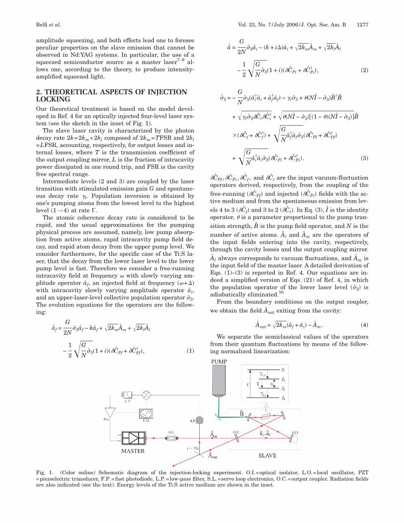
. THEORETICAL ASPECTS OF INJECTIONOCKINGur theoretical treatment is based on the model devel-ped in Ref. 4 for an optically injected four-level laser sys-em (see the sketch in the inset of Fig. 1).
The slave laser cavity is characterized by the photonecay rate 2k=2km+2kl composed of 2km=TFSR and 2klLFSR, accounting, respectively, for output losses and in-
ernal losses, where T is the transmission coefficient ofhe output coupling mirror, L is the fraction of intracavityower dissipated in one round trip, and FSR is the cavityree spectral range.
Intermediate levels (2 and 3) are coupled by the laserransition with stimulated emission gain G and spontane-us decay rate �t. Population inversion is obtained byne’s pumping atoms from the lowest level to the highestevel �1→4� at rate �.
The atomic coherence decay rate is considered to beapid, and the usual approximations for the pumpinghysical process are assumed, namely, low pump absorp-ion from active atoms, rapid intracavity pump field de-ay, and rapid atom decay from the upper pump level. Weonsider furthermore, for the specific case of the Ti:S la-er, that the decay from the lower laser level to the lowerump level is fast. Therefore we consider a free-runningntracavity field at frequency � with slowly varying am-litude operator af, an injected field at frequency ��+��ith intracavity slowly varying amplitude operator ai,nd an upper-laser-level collective population operator �3.he evolution equations for the operators are the follow-
ng:
af =G
2N�3af − kaf + �2kmAm + �2klAl
−1
2�G
N�3�1 + i���CPf + �CPf
† �, �1�
ig. 1. (Color online) Schematic diagram of the injection-lpiezoelectric transducer, F.P.=fast photodiode, L.P.=low-pass fire also indicated (see the text). Energy levels of the Ti:S active
a =G
2N�3ai − �k + i��ai + �2kmAm + �2klAl
−1
2�G
N�3�1 + i���CPi + �CPi
† �, �2�
�3 = −G
N�3�ai
†ai + af†af� − �t�3 + ��NI − �3�B†B
+ ��t�3�Ct�Ct† + ���NI − �3���1 − ���NI − �3��B
���Cf + �Cf†� +�G
Naf
†af�3��CPf + �CPf† �
+�G
Nai
†ai�3��CPi + �CPi† �. �3�
CPf ,�CPi ,�Cf , and �Ct are the input vacuum-fluctuationperators derived, respectively, from the coupling of theree-running ��CPf� and injected ��CPi� fields with the ac-ive medium and from the spontaneous emission from lev-ls 4 to 3 ��Cf� and 3 to 2 ��Ct�. In Eq. (3), I is the identityperator, � is a parameter proportional to the pump tran-ition strength, B is the pump field operator, and N is theumber of active atoms. Al and Am are the operators ofhe input fields entering into the cavity, respectively,hrough the cavity losses and the output coupling mirror.ˆ
l always corresponds to vacuum fluctuations, and Am ishe input field of the master laser. A detailed derivation ofqs. (1)–(3) is reported in Ref. 4. Our equations are in-eed a simplified version of Eqs. (21) of Ref. 4, in whichhe population operator of the lower laser level ��2� isdiabatically eliminated.10
From the boundary conditions on the output coupler,e obtain the field Aout exiting from the cavity:
Aout = �2km�af + ai� − Am. �4�
We separate the semiclassical values of the operatorsrom their quantum fluctuations by means of the follow-ng normalized linearization:
experiment. O.I.=optical isolator, L.O.=local oscillator, PZT.L.=servo loop electronics, O.C.=output coupler. Radiation fieldsm are shown in the inset.
ockinglter, Smediu
wta
wt
Fd
wrltwfica
w�
t
w=
t−s=
qts
wfl
1278 J. Opt. Soc. Am. B/Vol. 23, No. 7 /July 2006 Belfi et al.
af
�N� f + �af,
ai
�N� i exp�i� + �ai,
Am,l
�N� Am,l + �Am,l,
�3
N� J3 + ��3,
B
�N� B + �B,
here f, i, J3, B, and Am are real quantities, Al=0, andis the phase shift between the intracavity field i and
he input field Am. The semiclassical evolution equationsre
f = �G
2J3 − kf, �5�
i = �G
2J3 − ki + �2kmAm cos , �6�
= − � − �2km
Am
isin , �7�
J3 = − GJ3�i2 + f
2� − ��t + ��J3 + �, �8�
here �=�B2N is the pump rate. The steady-state solu-ions for the free-running case �Am=i=0� are
f2 =
��G − 2k� − 2k�t
2kG� 2,
J3 =2k
G� J.
rom Eqs. (6) and (7) we infer a critical value �l of theetuning �, called locking range, as
�l = �2km
Am
= 2km� Pm
Pfree, �9�
here Pm is the injected mode power and Pfree is the free-unning emission power. When �=�l, the intracavityoss–gain balance of the injected mode equals the one ofhe free-running mode. For ���l, f and i coexist, ande expect on the output a beat note between the two laserelds. On the contrary, when ���l (injection-lockingondition), f=0 is a solution of the stationary equations,nd for the steady-state solutions we obtain
� − arcsin� �
�l � , �10�
i2 � 2, �11�
J3 � J, �12�
here the approximated relations are valid if we assumel�2k.It is, furthermore, useful to define the following quan-
ities, with clear physical meaning:
�th =2k�t
G − 2k�threshold pump rate�,
�RO2 = G2J2 = 2k�t�� − 1�
�relaxation oscillation resonance frequency�,
�L = � + �t + G2 = ���t + �th� �damping constant�,
here � is the pump parameter �=� /�thPPump/Pthreshold.Introducing, for the generic field h, its rescaled quadra-
ure fluctuations �Xh=�h+�h† (amplitude) and �Xh−=�h
�h† (phase), we obtain the following equations for the la-er fluctuations, inside the injection-locking regime �af0�,
�X˙
ai= − �l cos �Xai
− i��Xai
− + G cos ��3 + �2km�XAm
+ �2kl�XAl− �GJ�XCPi
�cos − sin �, �13�
�X˙
ai
− = − i��Xai− �l cos �Xai
− + iG sin ��3 + �2km�XAm
−
+ �2kl�XAl
− − �GJ�XCPi�cos + sin �, �14�
��3 = − GJ cos �Xai+ iGJ sin �Xai
− − �L��3
+ ���1 − J��XB + ��tJ�Ct�Ct† + �GJ�XCPi
. �15�
Fourier transforming, we solve for the intracavityuadrature fluctuations �Xai
+,−�����Xai
+,−, and then, usinghe boundary conditions at the output coupling mirrorurface,
�Xout = �2km�Xai− �XAm
, �16�
�Xout− = �2km�Xai
− − �XAm
− , �17�
e arrive at the following expression for the quadratureuctuations �X and �X− exiting the cavity:
out out
b
w
T
B
Belfi et al. Vol. 23, No. 7 /July 2006 /J. Opt. Soc. Am. B 1279
�Xout = �i� − �l cos +�RO
2
i� − �L+
�l2 sin2
i� − �l cos −1�− 2km�1 +
�RO2 sin2
�i� − �L��i� − �l cos �� + i� − �l cos +�RO
2
i� − �L
+�l
2 sin2
i� − �l cos ��XAm
− i�2km
�l sin �i� − �L� + �RO2 cos sin
�i� − �L��i� − �l cos � ��XAm
− − �4kmkl �1
+�RO
2 sin2
�i� − �L��i� − �l cos ���XAl+ i��l sin �i� − �L� + �RO
2 cos sin
�i� − �L��i� − �l cos � ���XAl
− + iG
i� − �L�cos −
�l sin2
i� − �l cos
��2km���1 − J��XB + �2km�tJ�Ct�Ct†� + �2kmGJ�� G2
i� − �L+ 1�1 −
�l sin2
i� − �l cos − sin −
�l sin cos
i� − �l cos
−�RO
2 sin
�i� − �L��i� − �l cos ���XCpi� , �18�
�Xout− = �i� − �l cos +
�RO2
i� − �L+
�l2 sin2
i� − �l cos −1�− 2km�1 +
�RO2 cos2
�i� − �L��i� − �l cos �� + i� − �l cos +�RO
2
i� − �L
+�l
2 sin2
i� − �l cos ��XAm
− − i�2km
�l sin �i� − �L� − �RO2 cos sin
�i� − �L��i� − �l cos � ��XAm− �4kmkl �1
+�RO
2 cos2
�i� − �L��i� − �l cos ���XAl
− + i��l sin �i� − �L� + �RO2 cos sin
�i� − �L��i� − �l cos � ���XAl+ i
G
i� − �L�sin −
�l sin cos
i� − �l cos
��2km���1 − J��XB + �2km�tJ�Ct�Ct†� + i�2kmGJ�� G2
i� − �L+ 1�1 +
�l sin cos
i� − �l cos + cos −
�l sin2
i� − �l cos
+�RO
2 cos
�i� − �L��i� − �l cos ���XCpi� . �19�
The relevant physical quantity to be calculated is the fluctuations �Nout��� of the photon number Nout= Aout† Aout emitted
y the laser:
�Nout = Aout��Xout cos out − i�Xout− sin out�,
here out is the phase of the field Aout:
out = arctan�sin
cos +�l
2km� . �20�
he shot-noise-normalized noise spectrum of the output measured radiation is defined as
Vout =���Nout�2�
Aout2 .
y considering again �l�2km (low injection power), we have � out and
Vout � ��i� − �l cos +�RO
2
i� − �L+
�l2 sin2
i� − �l cos �2−1
� ��2km + i� − �l cos +�RO
2
i� − �L+
�l2 sin2
i� − �l cos cos
+ 2km
�l sin2
i� − �l cos �2
Vm + ��2km + i� − �l cos +�RO
2
i� − �L+
�l2 sin2
i� − �l cos sin − 2km
�l sin cos
i� − �l cos �2
Vm−
+ 2km� �
�th �t�RO
2
�2 + �L2 VPump + 2km
�t�RO2
�2 + �L2 + 4kmkl�cos +
�l sin2
i� − �l cos + i�sin +
�l sin cos
i� − �l cos �2
+ 4kmk��i� − ��
+ �t���cos + sin � −�l sin �2� , �21�
i� − �l cos
witntc
To(
TstfttneFhapf
nt�
q�i
h�aporalt
wcJ
trt�tt
gdh
FVPe2
Fcf=2
1280 J. Opt. Soc. Am. B/Vol. 23, No. 7 /July 2006 Belfi et al.
here Vm, Vm− , and VPump are, respectively, the normal-
zed spectra of the two master laser quadratures and ofhe pump laser amplitude quadrature. One obtains theoise spectrum in the free-running regime by consideringhat just vacuum fluctuations are injected into the slaveavity:
�Am = �Avac. �22�
he normalized noise spectrum for the free-running laser,btained by one’s putting Am=0 and �=0 in expression21), is
Vfree = 1 +1
��RO2 − �2�2 + �2�L
2 4km2 ��2 + �L
2� − 4km�RO2 �L
+ 2km�t�RO2 � �
�thVPump + 2km�t�RO
2 + 4kmk���2�
+ �� + �t�2� + 4kmkl��L2 + �2�� . �23�
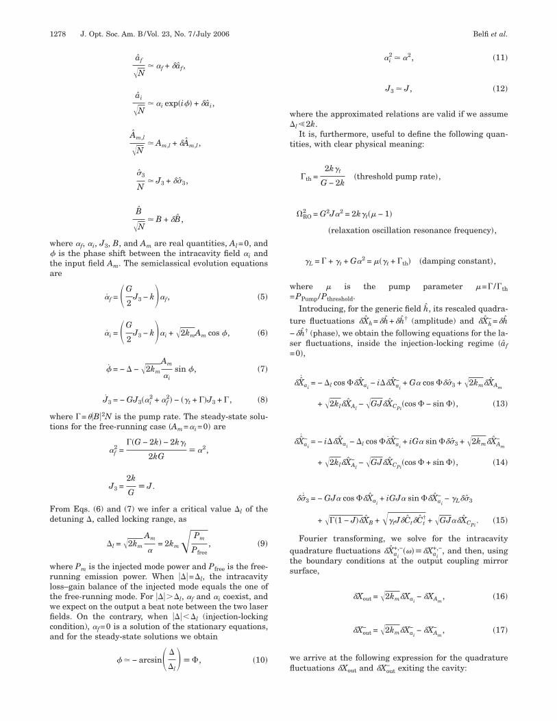
his expression coincides with Eq. (16) of Ref. 4, where weet J2=0 and J1=1−J3. For ���RO (near dc), the spec-rum is determined essentially by pump noise, whereas,or ���RO (frequency higher than tens of megahertz),he slave cavity filters out pump noise and the spectrumends to the quantum noise limit (QNL) of the vacuumoise. Examples of Vfree�2��� for our experimental param-ters and different values of pump power are shown inig. 2. Increasing the pump produces a simultaneous en-ancement of the relaxation oscillation resonance �ROnd of the damping term �L. For large values of pumpower (curve iii) the resonant peak at �RO/2� disappearsrom the spectrum, since �L approaches �RO.
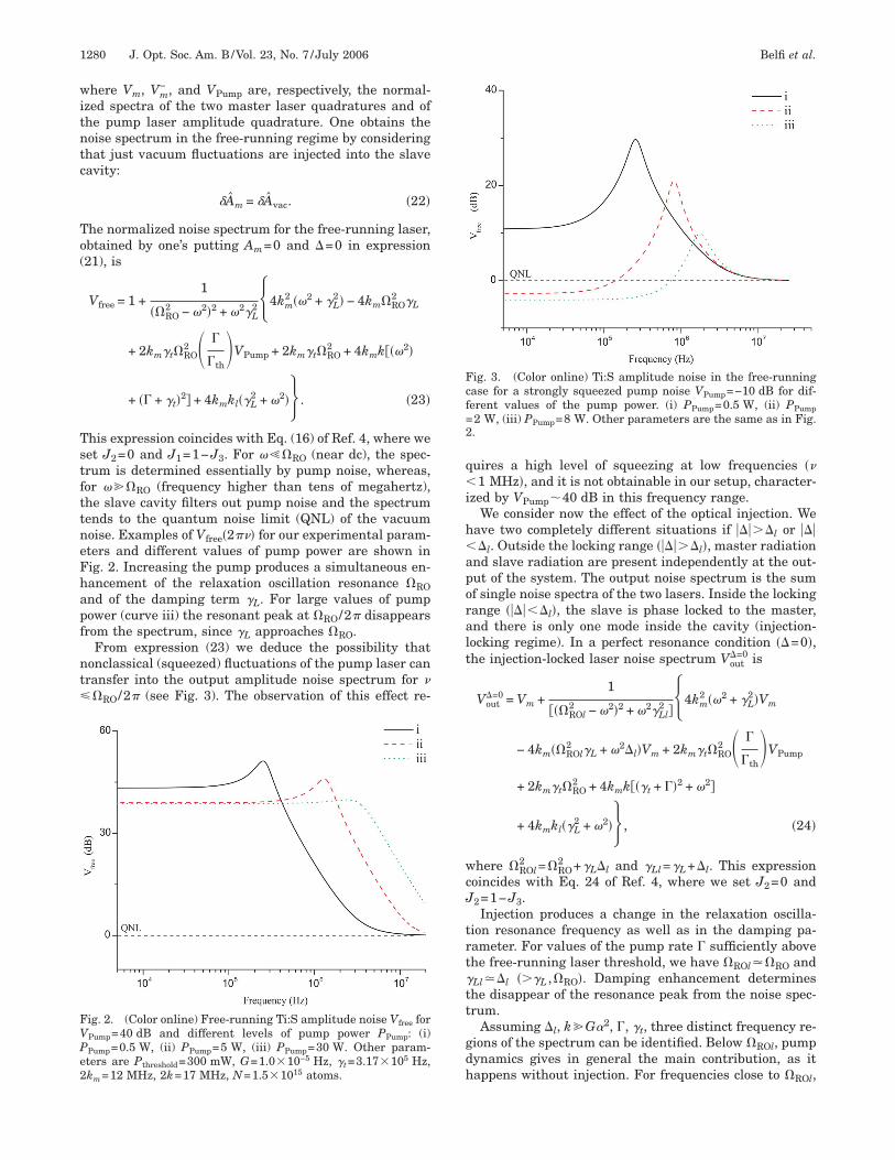
From expression (23) we deduce the possibility thatonclassical (squeezed) fluctuations of the pump laser canransfer into the output amplitude noise spectrum for �
�RO/2� (see Fig. 3). The observation of this effect re-
ig. 2. (Color online) Free-running Ti:S amplitude noise Vfree forPump=40 dB and different levels of pump power PPump: (i)Pump=0.5 W, (ii) PPump=5 W, (iii) PPump=30 W. Other param-ters are Pthreshold=300 mW, G=1.0�10−5 Hz, �t=3.17�105 Hz,k =12 MHz, 2k=17 MHz, N=1.5�1015 atoms.
muires a high level of squeezing at low frequencies ��1 MHz�, and it is not obtainable in our setup, character-
zed by VPump�40 dB in this frequency range.We consider now the effect of the optical injection. We
ave two completely different situations if ���l or ��l. Outside the locking range ����l�, master radiation
nd slave radiation are present independently at the out-ut of the system. The output noise spectrum is the sumf single noise spectra of the two lasers. Inside the lockingange ����l�, the slave is phase locked to the master,nd there is only one mode inside the cavity (injection-ocking regime). In a perfect resonance condition ��=0�,he injection-locked laser noise spectrum Vout
�=0 is
Vout�=0 = Vm +
1
���ROl2 − �2�2 + �2�Ll
2 � 4km2 ��2 + �L
2�Vm
− 4km��ROl2 �L + �2�l�Vm + 2km�t�RO
2 � �
�thVPump
+ 2km�t�RO2 + 4kmk���t + ��2 + �2�
+ 4kmkl��L2 + �2�� , �24�
here �ROl2 =�RO
2 +�L�l and �Ll=�L+�l. This expressionoincides with Eq. 24 of Ref. 4, where we set J2=0 and2=1−J3.Injection produces a change in the relaxation oscilla-
ion resonance frequency as well as in the damping pa-ameter. For values of the pump rate � sufficiently abovehe free-running laser threshold, we have �ROl��RO andLl��l ���L ,�RO�. Damping enhancement determineshe disappear of the resonance peak from the noise spec-rum.
Assuming �l, k�G2, �, �t, three distinct frequency re-ions of the spectrum can be identified. Below �ROl, pumpynamics gives in general the main contribution, as itappens without injection. For frequencies close to � ,
ig. 3. (Color online) Ti:S amplitude noise in the free-runningase for a strongly squeezed pump noise VPump=−10 dB for dif-erent values of the pump power. (i) PPump=0.5 W, (ii) PPump2 W, (iii) PPump=8 W. Other parameters are the same as in Fig..
ROl
islarhctfis
esstesian
mttimrtwptpaabFv
dp
wt(
3ANasvdasllwr
ifihticocaett
FaPCVt
FwVc=vae
Belfi et al. Vol. 23, No. 7 /July 2006 /J. Opt. Soc. Am. B 1281
nside a bandwidth of the order of �l, the slave laser istrongly sensitive to external modulations and behavesike an amplifier for the master fluctuations. When thenalysis frequency is increased, the amplification effect iseduced and, for �→� (above few tens of megahertz), weave Vout�Vm; i.e., the injection-locked laser fluctuationsoincide with those of the master laser. Intuitively, athese frequencies, intracavity-produced fluctuations areltered by the cavity itself while master fluctuations areimply outreflected by the output coupling mirror.
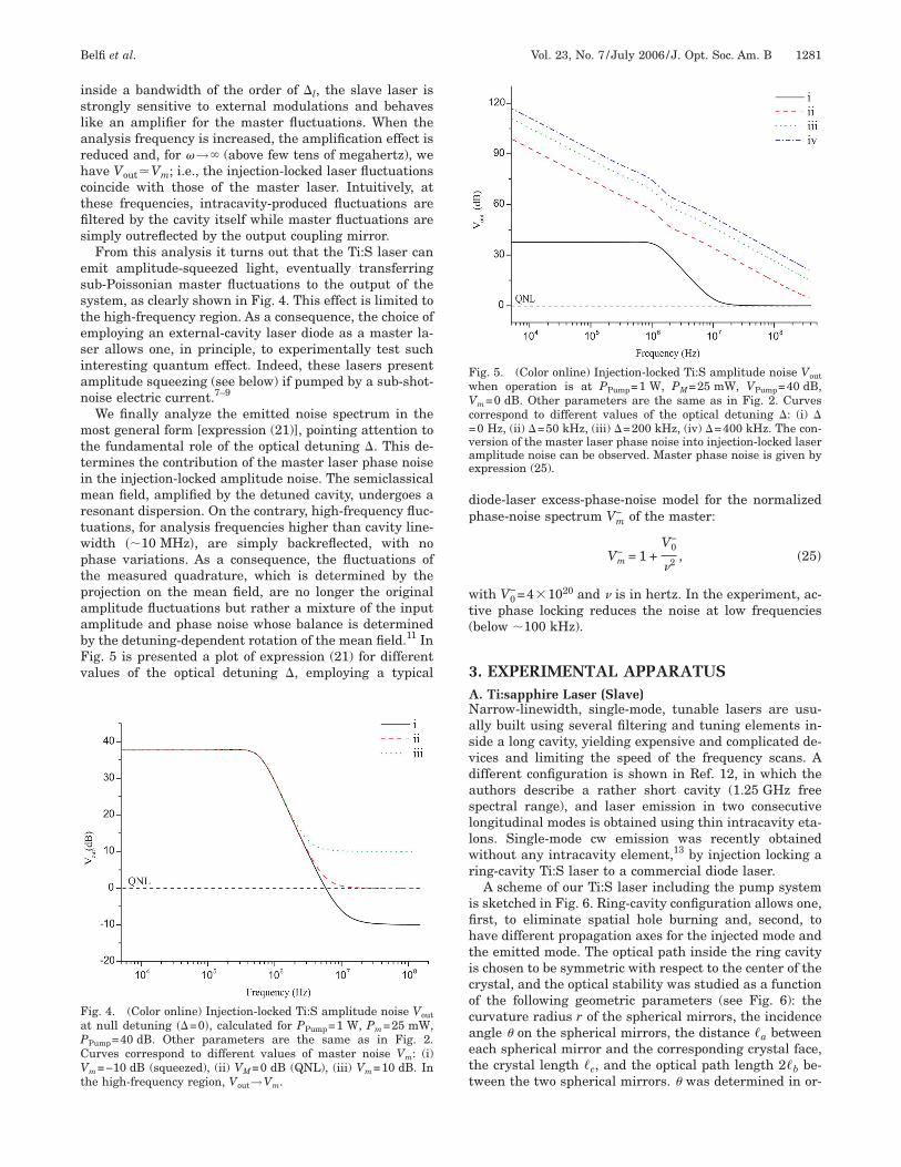
From this analysis it turns out that the Ti:S laser canmit amplitude-squeezed light, eventually transferringub-Poissonian master fluctuations to the output of theystem, as clearly shown in Fig. 4. This effect is limited tohe high-frequency region. As a consequence, the choice ofmploying an external-cavity laser diode as a master la-er allows one, in principle, to experimentally test suchnteresting quantum effect. Indeed, these lasers presentmplitude squeezing (see below) if pumped by a sub-shot-oise electric current.7–9
We finally analyze the emitted noise spectrum in theost general form [expression (21)], pointing attention to
he fundamental role of the optical detuning �. This de-ermines the contribution of the master laser phase noisen the injection-locked amplitude noise. The semiclassical
ean field, amplified by the detuned cavity, undergoes aesonant dispersion. On the contrary, high-frequency fluc-uations, for analysis frequencies higher than cavity line-idth ��10 MHz�, are simply backreflected, with nohase variations. As a consequence, the fluctuations ofhe measured quadrature, which is determined by therojection on the mean field, are no longer the originalmplitude fluctuations but rather a mixture of the inputmplitude and phase noise whose balance is determinedy the detuning-dependent rotation of the mean field.11 Inig. 5 is presented a plot of expression (21) for differentalues of the optical detuning �, employing a typical
ig. 4. (Color online) Injection-locked Ti:S amplitude noise Voutt null detuning ��=0�, calculated for PPump=1 W, Pm=25 mW,Pump=40 dB. Other parameters are the same as in Fig. 2.urves correspond to different values of master noise Vm: (i)m=−10 dB (squeezed), (ii) VM=0 dB (QNL), (iii) Vm=10 dB. In
he high-frequency region, V →V .
out miode-laser excess-phase-noise model for the normalizedhase-noise spectrum Vm
− of the master:
Vm− = 1 +
V0−
�2 , �25�
ith V0−=4�1020 and � is in hertz. In the experiment, ac-
ive phase locking reduces the noise at low frequenciesbelow �100 kHz).
. EXPERIMENTAL APPARATUS. Ti:sapphire Laser (Slave)arrow-linewidth, single-mode, tunable lasers are usu-lly built using several filtering and tuning elements in-ide a long cavity, yielding expensive and complicated de-ices and limiting the speed of the frequency scans. Aifferent configuration is shown in Ref. 12, in which theuthors describe a rather short cavity (1.25 GHz freepectral range), and laser emission in two consecutiveongitudinal modes is obtained using thin intracavity eta-ons. Single-mode cw emission was recently obtainedithout any intracavity element,13 by injection locking a
ing-cavity Ti:S laser to a commercial diode laser.A scheme of our Ti:S laser including the pump system
s sketched in Fig. 6. Ring-cavity configuration allows one,rst, to eliminate spatial hole burning and, second, toave different propagation axes for the injected mode andhe emitted mode. The optical path inside the ring cavitys chosen to be symmetric with respect to the center of therystal, and the optical stability was studied as a functionf the following geometric parameters (see Fig. 6): theurvature radius r of the spherical mirrors, the incidencengle � on the spherical mirrors, the distance �a betweenach spherical mirror and the corresponding crystal face,he crystal length �c, and the optical path length 2�b be-ween the two spherical mirrors. � was determined in or-
ig. 5. (Color online) Injection-locked Ti:S amplitude noise Vouthen operation is at PPump=1 W, PM=25 mW, VPump=40 dB,m=0 dB. Other parameters are the same as in Fig. 2. Curves
orrespond to different values of the optical detuning �: (i) �0 Hz, (ii) �=50 kHz, (iii) �=200 kHz, (iv) �=400 kHz. The con-ersion of the master laser phase noise into injection-locked lasermplitude noise can be observed. Master phase noise is given byxpression (25).
dtwg=urTh5pml
etpt
cdtc(
tclwttwP
l
acdpcpt
itatwatamsinucfcoe
pTl
BTmapTqtgsttptq1adtsttm
CT(tiop
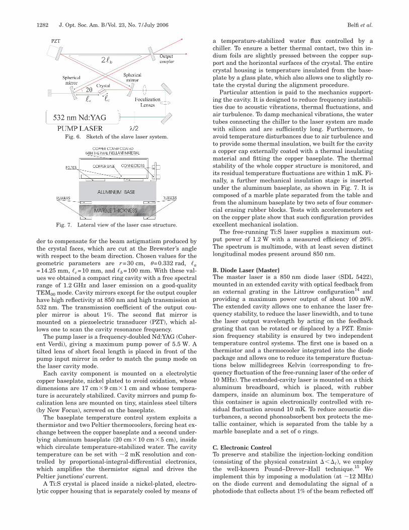
1282 J. Opt. Soc. Am. B/Vol. 23, No. 7 /July 2006 Belfi et al.
er to compensate for the beam astigmatism produced byhe crystal faces, which are cut at the Brewster’s angleith respect to the beam direction. Chosen values for theeometric parameters are r=30 cm, �=0.332 rad, �a14.25 mm, �c=10 mm, and �b=100 mm. With these val-es we obtained a compact ring cavity with a free spectralange of 1.2 GHz and laser emission on a good-qualityEM00 mode. Cavity mirrors except for the output couplerave high reflectivity at 850 nm and high transmission at32 nm. The transmission coefficient of the output cou-ler mirror is about 1%. The second flat mirror isounted on a piezoelectric transducer (PZT), which al-
ows one to scan the cavity resonance frequency.The pump laser is a frequency-doubled Nd:YAG (Coher-
nt Verdi), giving a maximum pump power of 5.5 W. Ailted lens of short focal length is placed in front of theump input mirror in order to match the pump mode onhe laser cavity mode.
Each cavity component is mounted on a electrolyticopper baseplate, nickel plated to avoid oxidation, whoseimensions are 17 cm�9 cm�1 cm and whose tempera-ure is accurately stabilized. Cavity mirrors and pump fo-alization lens are mounted on tiny, stainless steel tiltersby New Focus), screwed on the baseplate.
The baseplate temperature control system exploits ahermistor and two Peltier thermocoolers, forcing heat ex-hange between the copper baseplate and a second under-ying aluminum baseplate �20 cm�10 cm�5 cm�, insidehich circulate temperature-stabilized water. The cavity
emperature can be set with �2 mK resolution and con-rolled by proportional-integral-differential electronics,hich amplifies the thermistor signal and drives theeltier junctions’ current.A Ti:S crystal is placed inside a nickel-plated, electro-
ytic copper housing that is separately cooled by means of
Fig. 7. Lateral view of the laser case structure.
Fig. 6. Sketch of the slave laser system.
temperature-stabilized water flux controlled by ahiller. To ensure a better thermal contact, two thin in-ium foils are slightly pressed between the copper sup-ort and the horizontal surfaces of the crystal. The entirerystal housing is temperature insulated from the base-late by a glass plate, which also allows one to slightly ro-ate the crystal during the alignment procedure.
Particular attention is paid to the mechanics support-ng the cavity. It is designed to reduce frequency instabili-ies due to acoustic vibrations, thermal fluctuations, andir turbulence. To damp mechanical vibrations, the waterubes connecting the chiller to the laser system are madeith silicon and are sufficiently long. Furthermore, tovoid temperature disturbances due to air turbulence ando provide some thermal insulation, we built for the cavitycopper cap externally coated with a thermal insulatingaterial and fitting the copper baseplate. The thermal
tability of the whole copper structure is monitored, andts residual temperature fluctuations are within 1 mK. Fi-ally, a further mechanical insulation stage is insertednder the aluminum baseplate, as shown in Fig. 7. It isomposed of a marble plate separated from the table androm the aluminum baseplate by two sets of four commer-ial erasing rubber blocks. Tests with accelerometers setn the copper plate show that such configuration providesxcellent mechanical isolation.
The free-running Ti:S laser supplies a maximum out-ut power of 1.2 W with a measured efficiency of 26%.he spectrum is multimode, with at least seven distinct
ongitudinal modes present around 850 nm.
. Diode Laser (Master)he master laser is a 850 nm diode laser (SDL 5422),ounted in an extended cavity with optical feedback from
n external grating in the Littrow configuration14 androviding a maximum power output of about 100 mW.he extended cavity allows one to enhance the laser fre-uency stability, to reduce the laser linewidth, and to tunehe laser output wavelength by acting on the feedbackrating that can be rotated or displaced by a PZT. Emis-ion frequency stability is ensured by two independentemperature control systems. The first one is based on ahermistor and a thermocooler integrated into the diodeackage and allows one to reduce its temperature fluctua-ions below millidegrees Kelvin (corresponding to fre-uency fluctuation of the free-running laser of the order of0 MHz). The extended-cavity laser is mounted on a thickluminum breadboard, which is placed, with rubberampers, inside an aluminum box. The temperature ofhis container is again electronically controlled with re-idual fluctuation around 10 mK. To reduce acoustic dis-urbances, a second phonoabsorbent box protects the me-allic container, which is separated from the table by aarble baseplate and a set of o rings.
. Electronic Controlo preserve and stabilize the injection-locking conditionconsisting of the physical constraint ����), we employhe well-known Pound–Drever–Hall technique.15 Wemplement this by imposing a modulation (at �12 MHz)n the diode current and demodulating the signal of ahotodiode that collects about 1% of the beam reflected off
tta
tsp8ltnpdtsOtm
eto�q(ctp
mtietsqsclwl
DWmp
pcodi
mssntobt
Fpm
FcT(Pb
Belfi et al. Vol. 23, No. 7 /July 2006 /J. Opt. Soc. Am. B 1283
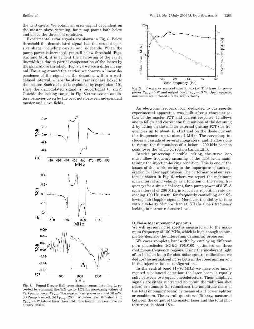
he Ti:S cavity. We obtain an error signal dependent onhe master–slave detuning, for pump power both belownd above the threshold condition.Experimental error signals are shown in Fig. 8. Below
hreshold the demodulated signal has the usual disper-ive shape, including carrier and sidebands. When theump power is increased, yet still below threshold [Figs.(a) and 8(b)], it is evident the narrowing of the cavityinewidth is due to partial compensation of the losses byhe gain. Above threshold [Fig. 8(c)] we see a different sig-al. Focusing around the carrier, we observe a linear de-endence of the signal on the detuning within a well-efined interval, where the slave laser is phase locked tohe master. Such a shape is explained by expression (10),ince the demodulated signal is proportional to sin .utside the locking range, in Fig. 8(c) we see an oscilla-
ory behavior given by the beat note between independentaster and slave fields.
ig. 8. Pound-Drever-Hall error signals versus detuning �, re-orded by scanning the Ti:S cavity PZT for increasing values ofi:S pump power PPump. The master laser power is about 20 mW.
a) Pump laser off. (b) PPump=200 mW (below laser threshold). (c)Pump=4 W (above laser threshold). The horizontal axes have ar-itrary offsets.
An electronic feedback loop, dedicated to our specificxperimental apparatus, was built after a characteriza-ion of the master PZT and current response. It allowsne to follow and correct the fluctuations of the detuning
by acting on the master external grating PZT (for fre-uencies up to about 10 kHz) and on the diode currentfor frequencies up to about 1 MHz). The servo loop in-ludes a cascade of several integrators, and it allows oneo reduce the fluctuations of � below �200 kHz peak toeak (over the whole correction bandwidth).Besides preserving a stable locking, the servo loopust allow frequency scanning of the Ti:S laser, main-
aining the injection-locking condition. This is one of thessues of this work, owing to the importance of such op-ration for laser applications. The performance of our sys-em is shown in Fig. 9, where we report the maximumcan interval and velocity as a function of the sweep fre-uency (for a sinusoidal scan), for a pump power of 5 W. Acan interval of 200 MHz is kept at a repetition rate ex-eeding 100 Hz, useful for frequently controlling and fol-owing sub-Doppler signals. Moreover, the ability to tuneith a velocity of more than 50 GHz/s allows frequency
ocking to narrow reference lines.
. Noise Measurement Apparatuse will present noise spectra measured up to the maxi-um frequency of 150 MHz, which is high enough to com-
letely describe the interesting dynamical processes.We cover complete bandwidth by employing different
-i-n photodiodes (EG&G FND100) optimized on threeontiguous frequency regions. Using the incoherent lightf an halogen lamp for shot-noise spectra calibration, weeduce the normalized noise both in the free-running andn the injection-locked configurations.
In the central band �1–70 MHz� we have also imple-ented a balanced detection: the laser beam is equally
plit between two equal photodetectors. Their amplifiedignals are either subtracted (to obtain the radiation shotoise) or summed (to reconstruct the amplitude noise ofhe total impinging beam) by means of a rf power splitterr combiners. The overall quantum efficiency, measuredetween the output of the master laser and the total pho-ocurrent, is about 18%.
ig. 9. Frequency scans of injection-locked Ti:S laser for pumpower PPump=5 W and output power Pout=0.9 W. Open squares,aximum scan; closed circles, scan velocity.
(afesmqrshHrpra
4TWrds�dn
ATaifrrto
1m
u
lntaf
rl
ig
Fli(i
Ffpoaf1uims
Ff7tcf
1284 J. Opt. Soc. Am. B/Vol. 23, No. 7 /July 2006 Belfi et al.
For the spectral measurement of high-power lasersTi:S and pump) we have used additional neutral filters tovoid photodetector saturation. The spectra are then re-erred to the complete laser radiation using the correctingxpression Scorr=1+ �Smeas−1� /�, where Smeas is the mea-ured power spectrum, Scorr is the corrected one (both nor-alized to their respective QNL), and � is the considered
uantum efficiency. Such procedure can be rather inaccu-ate, above all for low efficiency, if one wants to appreciatemall differences with respect to the QNL; therefore weave avoided it for the diode amplitude noise spectrum.owever, for noise spectra well above the QNL, as those
eported later, an error of few decibels is less than our ex-erimental uncertainty. On the other hand, the spectraeferred to the direct laser output are more interesting forppreciating the physics behind them.
. RESULTS AND COMPARISON WITHHEORYhen injection locked, the Ti:S ring laser becomes unidi-
ectional (light circulates inside the cavity following theirection imposed by the master), and its emission is on atable single mode. The threshold power is Pth
inj
290 mW (compared with 330 mW free running), and theifferential quantum efficiency is �inj�0.2 (0.26 free run-ing).
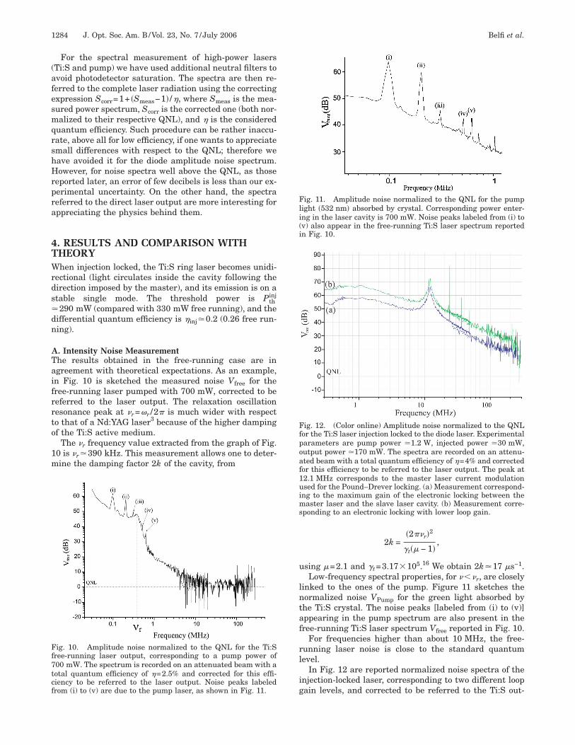
. Intensity Noise Measurementhe results obtained in the free-running case are ingreement with theoretical expectations. As an example,n Fig. 10 is sketched the measured noise Vfree for theree-running laser pumped with 700 mW, corrected to beeferred to the laser output. The relaxation oscillationesonance peak at �r=�r /2� is much wider with respecto that of a Nd:YAG laser3 because of the higher dampingf the Ti:S active medium.
The �r frequency value extracted from the graph of Fig.0 is �r�390 kHz. This measurement allows one to deter-ine the damping factor 2k of the cavity, from
ig. 10. Amplitude noise normalized to the QNL for the Ti:Sree-running laser output, corresponding to a pump power of00 mW. The spectrum is recorded on an attenuated beam with aotal quantum efficiency of �=2.5% and corrected for this effi-iency to be referred to the laser output. Noise peaks labeledrom (i) to (v) are due to the pump laser, as shown in Fig. 11.
2k =�2��r�2
�t�� − 1�,
sing �=2.1 and �t=3.17�105.16 We obtain 2k�17 �s−1.Low-frequency spectral properties, for ���r, are closely
inked to the ones of the pump. Figure 11 sketches theormalized noise VPump for the green light absorbed byhe Ti:S crystal. The noise peaks [labeled from (i) to (v)]ppearing in the pump spectrum are also present in theree-running Ti:S laser spectrum Vfree reported in Fig. 10.
For frequencies higher than about 10 MHz, the free-unning laser noise is close to the standard quantumevel.
In Fig. 12 are reported normalized noise spectra of thenjection-locked laser, corresponding to two different loopain levels, and corrected to be referred to the Ti:S out-
ig. 11. Amplitude noise normalized to the QNL for the pumpight �532 nm� absorbed by crystal. Corresponding power enter-ng in the laser cavity is 700 mW. Noise peaks labeled from (i) tov) also appear in the free-running Ti:S laser spectrum reportedn Fig. 10.
ig. 12. (Color online) Amplitude noise normalized to the QNLor the Ti:S laser injection locked to the diode laser. Experimentalarameters are pump power �1.2 W, injected power �30 mW,utput power �170 mW. The spectra are recorded on an attenu-ted beam with a total quantum efficiency of �=4% and correctedor this efficiency to be referred to the laser output. The peak at2.1 MHz corresponds to the master laser current modulationsed for the Pound–Drever locking. (a) Measurement correspond-
ng to the maximum gain of the electronic locking between theaster laser and the slave laser cavity. (b) Measurement corre-
ponding to an electronic locking with lower loop gain.
ptrich1tasi((tisnt
BSalQsdiCttPiQ
mcqnpQ�r
hpe
oPqiiFsoi
CTitalTortip
ttpctsh
FVb−pfiiqlt
Fdt
Belfi et al. Vol. 23, No. 7 /July 2006 /J. Opt. Soc. Am. B 1285
ut. By varying this parameter, we can control the fluc-uations of the detuning �, yet keep it within the lockingange �l. In both cases, the amplitude noise of thenjection-locked laser is much higher than that theoreti-ally calculated. Furthermore, for frequencies sufficientlyigher than the cavity linewidth, the noise level decays as/�2. At the maximum analysis frequency of 150 MHz,he noise level is still at least 10 dB above the QNL. Suchbehavior is typical of laser phase noise. Trace (b), corre-
ponding to a lower servo loop gain (large � fluctuations),ndicate higher noise (about 10 dB) with respect to tracea), which is recorded in a maximum loop gain conditionminimum � fluctuations). This suggests a direct correla-ion between detuning frequency fluctuations andnjection-locked laser amplitude noise. To better under-tand the link among injection-locked laser amplitudeoise, detuning fluctuations, and phase noise, it is impor-ant to analyze the master laser noise properties.
. Noise Properties of the Master Laseremiconductor lasers in an external grating configurationre characterized by low amplitude noise, falling even be-ow the QNL,8,9 and a strong phase noise, well above theNL.17 In Ref. 18 the authors have experimentally recon-
tructed the Wigner function for the quantum state of ra-iation emitted by a diode laser with the same character-stics as the one employed in our experiment.orresponding to the particular frequency of 58 MHz,
hat diode showed amplitude fluctuation of 0.5 dB belowhe QNL with a detection quantum efficiency of 20%.hase fluctuations at the same analysis frequency were,
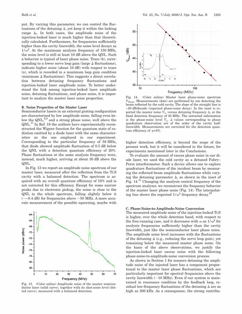
nstead, much higher, arriving at about 30 dB above theNL.In Fig. 13 we report an amplitude noise spectrum of ouraster laser, measured after the reflection from the Ti:S
avity with a balanced detection. The spectrum is ac-uired with an overall quantum efficiency of 18% and isot corrected for this efficiency. Except for some narroweaks due to electronic pickup, the noise is close to theNL in the whole spectrum, falling slightly below it
�−0.4 dB� for frequencies above �50 MHz. A more accu-ate measurement of the possible squeezing, maybe with
ig. 13. (Color online) Amplitude noise of the master semicon-uctor laser (solid curve), together with its shot-noise level (dot-ed curve), measured with a balanced detection.
igher detection efficiency, is beyond the scope of theresent work, but it will be considered in the future, forxperiments mentioned later in the Conclusions.
To evaluate the amount of excess phase noise in our di-de laser, we used the cold cavity as a detuned Fabry–erot interferometer. Such a device allows one to exploreuadrature fluctuations of the incident beam by measur-ng the reflected beam amplitude fluctuations while vary-ng the detuning parameter �, as shown in the inset ofig. 14.11 Changing the analysis central frequency of thepectrum analyzer, we reconstruct the frequency behaviorf the master laser phase noise (Fig. 14). The interpolat-ng line shows the expected 1/�2 frequency decay.19
. Phase-Noise-to-Amplitude-Noise Conversionhe measured amplitude noise of the injection-locked Ti:S
s higher, over the whole detection band, with respect tohe free-running case, and it decreases with � as 1/�2 fornalysis frequencies sufficiently higher than the cavityinewidth, just like the semiconductor laser phase noise.he amplitude noise level increases with the fluctuationsf the detuning � (e.g., reducing the servo loop gain), yetemaining below the measured master phase noise. Onhe basis of the above observations, we justify thenjection-locked laser excess noise with the followinghase-noise-to-amplitude-noise conversion process.As shown in Section 1 for nonzero detuning the ampli-
ude noise of the injected laser has a component propor-ional to the master laser phase fluctuations, which arearticularly important for spectral frequencies above theavity linewidth ��10 MHz�. Even if our system is main-ained in resonance condition by the feedback loop, re-idual low-frequency fluctuations of the detuning � are asigh as 200 kHz. As a consequence, the strong contribu-
ig. 14. (Color online) Master laser phase-noise spectrumPhase. Measurements (dots) are performed by our detecting theeam reflected by the cold cavity. The slope of the straight line is20 dB/decade (expected phase-noise decay). In the inset is re-orted the master noise Vm versus detuning frequency �, at thexed detection frequency of 30 MHz. The extracted information
s the phase-noise level Vq. � values corresponding to phaseuadrature observation are of the order of the cavity half-inewidth. Measurements are corrected for the detection quan-um efficiency of �=6%.
t3t
5WtTspi
tcspambcTfie
AWfbRp
e
R
1
1
1
1
1
1
1
1
1
1
2
2
2
1286 J. Opt. Soc. Am. B/Vol. 23, No. 7 /July 2006 Belfi et al.
ion of diode excess phase noise (55 dB above the QNL at0 MHz) appears, partially reduced, in the output ampli-ude fluctuations.
. CONCLUSIONSe have presented a compact Ti:S ring-cavity laser injec-
ion locked to an extended-cavity semiconductor source.he system has a good spectral purity and allows for fastcans, keeping the injection-locking condition. Theseroperties are useful for spectroscopic applications, e.g.,n double-frequency generation spectrometers.20
The analysis of the spectral properties of the laser sys-em shows good agreement between the model, originallyonceived for Nd:YAG lasers, and the experiment. Thequeezing properties of our semiconductor laser could, inrinciple, be transferred to the Ti:S, producing a quietnd powerful source. However, our theoretical and experi-ental analysis shows that such a possibility is prevented
y the conversion of the strong phase noise of the semi-onductor laser into amplitude noise of the injected Ti:S.o our knowledge, this effect had never been shown be-ore. To obtain sub-shot-noise emission, it will be interest-ng to work with low-phase-noise semiconductor lasers,.g., using resonant optical feedback.21,22
CKNOWLEDGMENTSe thank P. De Natale, D. Mazzotti, and P. Cancio Pastor
or useful discussions. This work was partially supportedy the Ministero dell’Istruzione, dell’Università e dellaicerca, Fundo per gli Investimenti della Ricerca di Baseroject RBNE01KZ94.F. Marin, the corresponding author, can be reached by
-mail at [email protected].
EFERENCES AND NOTES1. I. Freitag and H. Welling, “Investigation on amplitude and
frequency noise of injection-locked diode-pumped Nd:Yaglasers,” Appl. Phys. B 58, 537–544 (1994).
2. A. D. Farinas, E. K. Gustaffson, and R. L. Byer, “Frequencyand intensity noise in an injection-locked, solid-state laser,”J. Opt. Soc. Am. B 12, 328–334 (1995).
3. C. C. Harb, T. C. Ralph, E. H. Huntington, I. Freitag, D. E.McClelland, and H.-A. Bachor, “Intensity-noise propertiesof injection-locked lasers,” Phys. Rev. A 54, 4370–4382(1995).
4. T. C. Ralph, C. C. Harb, and H.-A. Bachor, “Intensity noiseproperties of injection-locked lasers: quantum theory usinga linearized input–output method,” Phys. Rev. A 54,4359–4369 (1996).
5. A. Bramati, J.-P. Hermier,V. Jost, and E. Giacobino,“Intensity noise of injected Nd:YVO4 microchip lasers,”Eur. Phys. J. D 19, 421–427 (2002).
6. A. Bramati, J.-P. Hermier, V. Jost, E. Giacobino, J. J.Aubert, E. Molva, and L. Fulbert, “Effects of pump
fluctuation on intensity noise of Nd:YVO4 microchiplasers,” Eur. Phys. J. D 6, 513–521 (1999).
7. S. Machida, Y. Yamamoto, and Y. Itaya, “Observation ofamplitude squeezing in a constant-current-drivensemiconductor laser,” Phys. Rev. Lett. 58, 1000–1003(1987).
8. M. J. Freeman, H. Wang, D. G. Steel, R. Craig, and D. R.Scifres, “Wavelength-tunable amplitude-squeezed lightfrom a room-temperature quantum-well laser,” Opt. Lett.18, 2141–2143 (1993).
9. F. Marin, A. Bramati, E. Giacobino, T. C. Zhang, J.-P.Poizat, J.-F. Roch, and P. Grangier, “Squeezing andintermode correlations in laser diodes,” Phys. Rev. Lett. 75,4606–4609 (1995).
0. The authors of Ref. 4 have agreed with the followingcorrections to that paper: (1) The field operators (af and ai)in the last term on the right side of the first two equations
(21) should not appear; (2) in Eqs. (21), G should be G, orG /N; and (3) the expression (23) for the output noise of theinjected laser is not correct, having been obtained from awrong definition of the output amplitude quadrature. Amore rigorous derivation of the noise terms can be found inT. C. Ralph, in Quantum Squeezing, P. D. Drummond andZ. Ficek, eds. (Springer-Verlag, 2004), pp. 141–170.
1. P. Galatola, L. Lugiato, M. Porreca, P. Tombesi, and G.Leuchs, “System control by variation of the squeezingphase,” Opt. Commun. 85, 95–103 (1991).
2. C. Zimmermann, V. Vuletic, A. Hemmerich, L. Ricci, and T.W. Hänsch, “Design for a compact tunable Ti:sapphirelaser,” Opt. Lett. 20, 297–299 (1995).
3. E. A. Cummings, M. S. Hicken, and S. D. Bergrson,“Demonstration of a 1-W injection-locked continuous-wavetitanium:sapphire laser,” Appl. Opt. 41, 7583–7587 (2002).
4. C. E. Wieman and L. Hollberg, “Using diode lasers foratomic physics,” Rev. Sci. Instrum. 62, 1–20 (1991).
5. R. W. P. Drever, J. L. Hall, F. W. Kowalski, J. Hough, G. M.Ford, A. J. Munley, and H. Ward, “Laser phase andfrequency stabilization using an optical resonator,” Appl.Phys. B 31, 97–105 (1983).
6. P. F. Moulton, “Spectroscopic and laser characteristics ofTi:Al2O3,” J. Opt. Soc. Am. B 3, 125–133 (1986).
7. T.-C. Zhang, J.-Ph. Poizat, P. Grelu, J.-F. Roch, P. Grangier,F. Marin, A. Bramati, V. Jost, M. D. Levenson, and E.Giacobino, “Quantum noise of free-running and externally-stabilized laser diodes,” Quantum Semiclassic. Opt. 7,601–613 (1995).
8. A. Zavatta, F. Marin, and G. Giacomelli, “Quantum-statereconstruction of a squeezed laser field by self-homodynetomography,” Phys. Rev. A 66, 043805 (2002).
9. A. L. Shawlow and C. H. Townes, “Infrared and opticalmasers,” Phys. Rev. 112, 1940–1949 (1958).
0. D. Mazzotti, P. De Natale, G. Giusfredi, C. Fort, J. A.Mitchell, and L. W. Hollberg, “Difference-frequencygeneration in PPLN at 4.25 �m: an analysis of sensitivitylimits for DFG spectrometers,” Appl. Phys. B 70, 747–750(2000).
1. B. Dahmani, L. Hollberg, and R. Drullinger, “Frequencystabilization of semiconductor lasers by resonant opticalfeedback,” Opt. Lett. 12, 876–878 (1987).
2. Y. Shevy, J. Iannelli, J. Kitching, and A. Yariv, “Self-quenching of the semiconductor laser linewidth below theSchawlow–Townes limit using optical feedback,” Opt. Lett.17, 661–663 (1992).