Tampering Attack on Any Key-based Logic Locked Circuits
22
TAAL: Tampering Aack on Any Key-based Logic Locked Circuits AYUSH JAIN, ZIQI ZHOU, and UJJWAL GUIN, Auburn University, USA Due to the globalization of semiconductor manufacturing and test processes, the system-on-a-chip (SoC) designers no longer design the complete SoC and manufacture chips on their own. This outsourcing of the design and manufacturing of Integrated Circuits (ICs) has resulted in several threats, such as overproduction of ICs, sale of out-of-specification/rejected ICs, and piracy of Intellectual Properties (IPs). Logic locking has emerged as a promising defense strategy against these threats. However, various attacks about the extraction of secret keys have undermined the security of logic locking techniques. Over the years, researchers have proposed different techniques to prevent existing attacks. In this paper, we propose a novel attack that can break any logic locking techniques that rely on the stored secret key. This proposed TAAL attack is based on implanting a hardware Trojan in the netlist, which leaks the secret key to an adversary once activated. As an untrusted foundry can extract the netlist of a design from the layout/mask information, it is feasible to implement such a hardware Trojan. All three proposed types of TAAL attacks can be used for extracting secret keys. We have introduced the models for both the combinational and sequential hardware Trojans that evade manufacturing tests. An adversary only needs to choose one hardware Trojan out of a large set of all possible Trojans to launch the TAAL attack. Additional Key Words and Phrases: Logic locking, IP Piracy, IC Overproduction, Hardware Trojans, Tampering ACM Reference Format: Ayush Jain, Ziqi Zhou, and Ujjwal Guin. 2020. TAAL: Tampering Attack on Any Key-based Logic Locked Circuits. ACM Trans. Des. Autom. Electron. Syst. 1, 1 (December 2020), 22 pages. https://doi.org/10.1145/ nnnnnnn.nnnnnnn 1 INTRODUCTION The continuous addition of new functionality in a system-on-a-chip (SoC) has enforced designers to adopt newer and lower technology nodes to manufacture chips primarily to reduce the overall area and the resultant cost of a chip. Building and maintaining such a fabrication plant (foundry) requires a multi-billion dollar investment [2]. As a result, the semiconductor industry has moved towards horizontal integration, where an SoC designer acquires intellectual properties (IPs) from many different vendors and sends the design to a foundry for manufacturing, which is generally located offshore. The hardware layers that were assumed to be trusted are no longer true with the outsourcing of IC fabrication in a globalized and distributed design flow, including multiple entities. Third-party IPs, fabrication, and test facilities of chips represent security threats to the current horizontal integration of the production. The security threats posed by these entities include – ( ) overproduction of ICs [4, 5, 9, 15, 24, 31, 63], where an untrusted foundry fabricates more chips without the consent Authors’ address: Ayush Jain, [email protected]; Ziqi Zhou, [email protected]; Ujjwal Guin, ujjwal.guin@auburn. edu, Auburn University, Department of Electrical and Computer Engineering, Auburn, AL, USA. Permission to make digital or hard copies of all or part of this work for personal or classroom use is granted without fee provided that copies are not made or distributed for profit or commercial advantage and that copies bear this notice and the full citation on the first page. Copyrights for components of this work owned by others than ACM must be honored. Abstracting with credit is permitted. To copy otherwise, or republish, to post on servers or to redistribute to lists, requires prior specific permission and/or a fee. Request permissions from [email protected]. © 2020 Association for Computing Machinery. 1084-4309/2020/12-ART $15.00 https://doi.org/10.1145/nnnnnnn.nnnnnnn ACM Trans. Des. Autom. Electron. Syst., Vol. 1, No. 1, Article . Publication date: December 2020. arXiv:1909.07426v2 [cs.CR] 11 Dec 2020
-
Upload
khangminh22 -
Category
Documents
-
view
0 -
download
0
Transcript of Tampering Attack on Any Key-based Logic Locked Circuits

TAAL: Tampering Attack on Any Key-based Logic LockedCircuits
AYUSH JAIN, ZIQI ZHOU, and UJJWAL GUIN, Auburn University, USA
Due to the globalization of semiconductor manufacturing and test processes, the system-on-a-chip (SoC)designers no longer design the complete SoC and manufacture chips on their own. This outsourcing of thedesign and manufacturing of Integrated Circuits (ICs) has resulted in several threats, such as overproductionof ICs, sale of out-of-specification/rejected ICs, and piracy of Intellectual Properties (IPs). Logic locking hasemerged as a promising defense strategy against these threats. However, various attacks about the extractionof secret keys have undermined the security of logic locking techniques. Over the years, researchers haveproposed different techniques to prevent existing attacks. In this paper, we propose a novel attack that canbreak any logic locking techniques that rely on the stored secret key. This proposed TAAL attack is basedon implanting a hardware Trojan in the netlist, which leaks the secret key to an adversary once activated.As an untrusted foundry can extract the netlist of a design from the layout/mask information, it is feasibleto implement such a hardware Trojan. All three proposed types of TAAL attacks can be used for extractingsecret keys. We have introduced the models for both the combinational and sequential hardware Trojans thatevade manufacturing tests. An adversary only needs to choose one hardware Trojan out of a large set of allpossible Trojans to launch the TAAL attack.
Additional KeyWords and Phrases: Logic locking, IP Piracy, IC Overproduction, Hardware Trojans, Tampering
ACM Reference Format:Ayush Jain, Ziqi Zhou, and Ujjwal Guin. 2020. TAAL: Tampering Attack on Any Key-based Logic LockedCircuits. ACM Trans. Des. Autom. Electron. Syst. 1, 1 (December 2020), 22 pages. https://doi.org/10.1145/nnnnnnn.nnnnnnn
1 INTRODUCTIONThe continuous addition of new functionality in a system-on-a-chip (SoC) has enforced designersto adopt newer and lower technology nodes to manufacture chips primarily to reduce the overallarea and the resultant cost of a chip. Building and maintaining such a fabrication plant (foundry)requires a multi-billion dollar investment [2]. As a result, the semiconductor industry has movedtowards horizontal integration, where an SoC designer acquires intellectual properties (IPs) frommany different vendors and sends the design to a foundry for manufacturing, which is generallylocated offshore.
The hardware layers that were assumed to be trusted are no longer true with the outsourcing of ICfabrication in a globalized and distributed design flow, including multiple entities. Third-party IPs,fabrication, and test facilities of chips represent security threats to the current horizontal integrationof the production. The security threats posed by these entities include – (𝑖) overproduction ofICs [4, 5, 9, 15, 24, 31, 63], where an untrusted foundry fabricates more chips without the consent
Authors’ address: Ayush Jain, [email protected]; Ziqi Zhou, [email protected]; Ujjwal Guin, [email protected], Auburn University, Department of Electrical and Computer Engineering, Auburn, AL, USA.
Permission to make digital or hard copies of all or part of this work for personal or classroom use is granted without feeprovided that copies are not made or distributed for profit or commercial advantage and that copies bear this notice andthe full citation on the first page. Copyrights for components of this work owned by others than ACM must be honored.Abstracting with credit is permitted. To copy otherwise, or republish, to post on servers or to redistribute to lists, requiresprior specific permission and/or a fee. Request permissions from [email protected].© 2020 Association for Computing Machinery.1084-4309/2020/12-ART $15.00https://doi.org/10.1145/nnnnnnn.nnnnnnn
ACM Trans. Des. Autom. Electron. Syst., Vol. 1, No. 1, Article . Publication date: December 2020.
arX
iv:1
909.
0742
6v2
[cs
.CR
] 1
1 D
ec 2
020

2 Jain et al.
of the SoC designer in order to generate revenue by selling them in the market, (𝑖𝑖) sale of out-of-specification/rejected ICs [21, 24, 25, 56, 104], and (𝑖𝑖𝑖) IP piracy [11, 14, 78, 79, 104], wherean entity in the supply chain can use, modify and/or sell functional IPs illegally. Over the years,researchers have proposed different techniques to prevent the aforementioned attacks and they areIC metering [4, 5, 40, 63], logic locking [24, 58, 63], hardware watermarking [19, 36, 53], and splitmanufacturing [33, 82].Logic locking has emerged as a promising technique and gained significant attention from
the researchers to address the different threats emerging from untrusted manufacturing. In logiclocking, the netlist of a circuit is locked so that it produces incorrect results unless it is programmedwith a secret key. The locks are generally inserted in the netlist using XOR gates. Traditionallogic locking methods involved selection of key gate location as random selection [25, 26, 63],strong interference-based selection [58], and fault-analysis based selection [60]. Over the years,researchers have also proposed different attacks to extract the secret key and undermine thelocking mechanisms. Boolean Satisfiability (SAT)-based attacks have demonstrated effective waysof extracting the secret keys. Countermeasures are also proposed so that SAT-based attacks becomeinfeasible.
This paper shows that any locked circuit, where the secret key is stored in an on-chip memoryno matter whether it is tamper-proof or not, can be broken by inserting a hardware Trojan. Wepresent this attack as TAAL: Tampering Attack on Any Locked circuit that uses a stored key forlocking the netlist. This attack can defeat the security measures provided from any existing logiclocking methods.We believe that we are the first to show that any key-based logic locked circuit can beexploited by inserting a hardware Trojan in the netlist. The contributions of this paper are describedas follows:
• We propose a novel attack based on malicious modifications of the netlist to target anykey-based locked circuit. The attacking approach is to tamper the locked netlist in orderto extract the secret key information. Once the valid key information is extracted from anactivated IC, an untrusted foundry can unlock any number of chips and sell overproducedand defective chips. As this attack applies to any key-based locked circuits, an adversarycan undermine any secure solutions proposed so far to prevent overproduction, sourcingdefective/out-of-spec chips, and IP piracy. Note that different researchers have proposed touse logic locking to prevent hardware Trojans [44, 65, 98, 101–103] as an adversary cannotprecisely specify the trigger conditions when a design is locked. However, we exploit a Trojanto obtain the secret key, which is the primary contribution of this paper.
• We present three types of TAAL attacks that extract the secret key differently using hardwareTrojans placed at different locations in the netlist. T1 type TAAL attack directly leaks thesecret key to the primary output of an IC once the Trojan is activated (see Figure 2.(a)). On theother hand, T2 type TAAL and T3 type TAAL attacks rely on the activation and propagationof the secret key to the primary output (see Figure 2.(b) and Figure 3 respectively). Notethat an adversary has the freedom of choosing one of these three types of TAAL attacksimplemented using combinational, sequential, or analog hardware Trojans.
• We present an existing well-known model for designing a combinational hardware Tro-jan [107], which can be used to launch the TAAL attacks. An adversary has the freedom tochoose the type of hardware Trojan, which can be designed so that it evades manufacturingor production tests and remains undetected. These combinational Trojans can be describedas Type-p Trojans, as they have 𝑝 trigger inputs. These triggers can come from the primaryinputs and/or internal nodes of a locked circuit, which are not affected by the keys. Wepresent that a very large number of Trojans can be created, and an adversary can use only
ACM Trans. Des. Autom. Electron. Syst., Vol. 1, No. 1, Article . Publication date: December 2020.

TAAL: Tampering Attack on Any Key-based Logic Locked Circuits 3
x1
x2
x3
x4
y
x1
x2
x3
x4
y
k
x1
x2
x3
x4
y
k
1
0
x1
x2
x3
x4
y
(b)
(c) (e)(d)
TM TM TM
k1 k2 k3 k4
Input OutputLocked
Circuit
Tamper-proof
Memory
Secret Key (K)
(a)
Fig. 1. Different logic locking techniques. (a) A locked circuit, where the secret key (𝐾) is programmed in atamper-proof memory (𝑇𝑀). (b) Original circuit. (c) XOR-based locking. (d) MUX-based locking. (e) LUT-basedlocking.
one such a Trojan. It is practically impossible for an SoC designer to detect all these feasibleTrojans using logic tests.
• We also present a model for sequential Trojan, which is constructed using a combinationalone. A state element (a counter) is added to a combinational Trojan to deliver the payloadonce it is triggered 𝑅 times consecutively. Note that the trigger inputs for both the Trojansare the same. The combinational Trojan delivers the payload once triggered; on the otherhand, a sequential Trojan needs to be triggered 𝑅 times consecutively. Note that an adversarycan choose any existing design of a hardware Trojan proposed so far.
The rest of the paper is organized as follows: an introduction to logic locking along with anoverview of different locking techniques and attacks is provided in Section 2. The proposed attacksbased on hardware Trojan to implement the malicious design modification for the extraction of thesecret key from any locked circuit are described in Section 3. We provide an algorithm for designingan Type-p combinational Trojan considering the set of manufacturing test patterns in Section 4.The number of valid Trojans, along with other factors such as area overhead and leakage powerfor several benchmark circuits, are presented in Section 5. The future directions are provided inSection 6. Finally, we conclude our paper in Section 7.
2 BACKGROUNDThe challenges for protecting a circuit against hardware security threats have been the driving forcefor developing different techniques to limit the amount of circuit information that can be recoveredby an adversary. Logic locking has emerged as a field of significant interest from the researchers, asit can provide complete protection against IC overproduction and IP piracy. Different researchershave proposed to use logic locking to prevent hardware Trojans as well [44, 65, 98, 101–103].
The objective of logic locking is to obfuscate the inner details of the circuit and make it infeasiblefor an adversary to reconstruct the original netlist. Logic Locking hides the circuit’s functionality byinserting additional logic gates into the original design, which we termed as key gates. In additionto the original inputs, the locked circuit needs secret key inputs to key gates from on-chip tamper-proof memory (see Figure 1.(𝑎) for details). The correct functionality of the design is obtained
ACM Trans. Des. Autom. Electron. Syst., Vol. 1, No. 1, Article . Publication date: December 2020.

4 Jain et al.
when the key inputs receive the proper secret key value. Applying an invalid key to the key gateswould result in incorrect functionality of the locked design. Note that for a securely locked circuit,the design details cannot be recovered using reverse engineering.Different logic locking methods were devised over the years and can be categorized into three
different categories. First, XOR-based logic locking, shown in Figure 1.(c), has received muchattention due to its simplicity. In this technique, a set of XOR or XNOR gates are inserted askey gates [24–26, 58, 63, 92, 97, 99, 100]. The secret key is stored in tamper-proof memory (TM),and connections are made from TM to the key gates. Second, in the MUX-based logic lockingtechnique [41, 52], multiplexers (MUX) are inserted so that one of its input is correct, which is theactual net of the circuit. The other input of the MUX is incorrect, which is a dummy net randomlyselected from the netlist. This technique is shown in Figure 1.(d). The select signal of the MUXis associated with the key bit from the tamper-proof memory. The correct signal goes throughthe MUX upon applying valid key value; otherwise, the incorrect signal propagates in the netlist.Third, in LUT-based logic locking, [9, 38, 44], shown in Figure 1.(e), a look-up table with severalkey inputs is used to lock the netlist. The LUTs replace a combinational logic in the design, makingit difficult to predict the output as it depends on several different key values.
The research community has proposed several attacks to exploit the security vulnerability on alogic locked circuit. Subramanyan et al. [74] first showed that a locked circuit could be broken usingBoolean Satisfiability (SAT) analysis. The SAT attack algorithm, attributed as an oracle-guidedattack, requires a locked netlist, which can be recovered using reverse engineering and functionalchip with a valid key stored/programmed in its tamper-proof memory. In this attack, an adversarycan query an activated chip and observe the response. Note that the SAT attack requires accessto the internal nodes of the circuit through the scan chains, which is common in today’s netlistfor implementing Design-for-Testability (DFT) [13]. The SAT attack works iteratively to eliminateincorrect key values from the key space using distinguishing input patters (DIPs). A DIP is definedas an input pattern for which two sets of hypothesis keys produce complementary results. Bycomparing these with the output of an unlocked chip, one set of hypothesis keys is discarded. TheSAT attack works efficiently as it discards multiple hypothesis keys in one iteration.Thereafter, researchers have focused on improving and developing locking techniques to be
resilient against the SAT attack. Subsequent work in this direction involved Anti-SAT [92, 93],SARLock [97], TTLock [100], SFLL [99], design-for-security (DFS) architecture [24–26]. Theseproposed techniques use one-point functions. SARlock inverts the output of the circuit for oneinput pattern corresponding to one incorrect key. This input pattern differs for different incorrectkeys. Anti-SAT involves two complementary external logic circuits which are supplied with thesame key values and same inputs. The output of these two circuits converge into a AND gate whoseoutput is always 0 for the correct key applied; else, it may be 1 that leads to corrupted internal nodevalue in the original netlist to produce incorrect outputs. Anti-SAT, initially, was proven vulnerableto the signal probability skew (SPS) [97] attack and removal/bypass attack [95]. SARLock wasbroken by Double DIP attack [68], Approximate SAT attack [66] and removal/bypass attack [95].
Due to limitations of SARlock, Yasin et al. developed an improved version of this design and re-ferred to as TTLock [100], where the original design itself is modified to produce corrupted/invertedresults upon applying an incorrect key for a single input pattern. Stripped functionality basedlogic locking (SFLL) [99] was proposed to provide more flexibility in the number of protectedinput patterns. The design is no longer the same as the original design due to stripped parts of thefunctionality resulting in erroneous output. A separate restore unit is responsible for removing thiserror in the output, supplying correct key values to it. However, Subramanyan et al. has shown thatSFLL can be defeated through FALL attack [71]. The attack is built on three primary steps, namely,structural analysis, functional analysis, and key confirmation. The structural analysis is performed
ACM Trans. Des. Autom. Electron. Syst., Vol. 1, No. 1, Article . Publication date: December 2020.

TAAL: Tampering Attack on Any Key-based Logic Locked Circuits 5
to identify the gates that are the output of the cube stripping function in SFLL. After identificationof these candidate gates, the functional analysis targets the property of cube stripping functions,which results in a set of potential key values. Finally, the key confirmation algorithm identifies thecorrect key from the set of potential key values.
As the SAT-attack is based on the availability of accessing the internal states of a circuit throughthe scan chains, Guin et al. proposed placing multiple flip-flops capturing signals controlled bydifferent key bits at the same level of the parallel scan chains, which were used in the current testcompression methodologies [24]. However, a vulnerability existed in this design, when an adversaryperforms multi-cycle tests, such as delay tests (transition delay faults and path delay faults) [13].This leads to the necessity for developing a new design-for-security (DFS) architecture to preventleaking of the key during any manufacturing tests [25, 26]. This design prevents scanning out theinternal states after a chip is being activated, and the keys are programmed/stored in the circuit.Apart from SAT-based attacks, probing attacks [55, 85] have also shown serious threats to the
security of logic locking, where an attacker makes contact with the probes at signal wires in orderto extract sensitive information, mainly, the secret key. With the help of a focused ion beam (FIB), apowerful circuit editing tool that can mill and deposit material with nanoscale precision, an attackercan circumvent protection mechanisms and reach wires carrying sensitive information. However,the countermeasures reflect the complexity of shield-structure and nanopyramid structures asthe defense, making it difficult to perform these attacks [67, 86]. Recently, Zhang et al. proposedan oracle less attack to extract the key from locked circuits [105]. The notion of this attack is tocompare the locked and unlocked instances of repeated Boolean functions in the netlist to predictthe key. A solution was proposed to countermeasure the attack as well.
3 PROPOSED TAAL ATTACK FOR EXTRACTING SECRET KEYSThe general hardware security strategy adopted for designing and manufacturing a circuit involvesa logic locking, where a chip is unlocked by storing a secret key in the tamper-proof memory. Asthis secret key is the same for all the chips manufactured with the same design, finding this keyfrom one chip undermines the security resulted from logic locking. We show that an adversarycan easily extract the key for a chip using our proposed TAAL attacks, built on tampering throughmalicious modification by inserting a hardware Trojan to a locked circuit. In this section, we willpresent three types of TAAL attacks.
3.1 Adversarial ModelThe adversarial model is given to defining the capabilities and intentions of an attacker clearly.In this model, the attacker (adversary) is assumed to be an untrusted foundry and possesses thefollowing:
• The attacker has access to the locked netlist of a circuit. An untrusted foundry has access toall the layout information, which can be extracted from the GDSII or OASIS file. The netlistcan be reconstructed from the layout using reverse engineering with advanced technologicaltools [80].
• The attacker can determine the location of the tamper-proof memory. It can also find thelocation of key gates in a netlist, as it can easily trace the route of the other input of the keygate to the tamper-proof memory.
• The attacker can tamper a netlist for its malicious intentions through inserting additionalcircuitry, commonly known as hardware Trojans, about which the SoC designer is unaware.
• The attacker has access to all the manufacturing test (e.g. stuck-at-fault, delay fault) patterns.Commonly, the production tests are performed at the foundry.
ACM Trans. Des. Autom. Electron. Syst., Vol. 1, No. 1, Article . Publication date: December 2020.

6 Jain et al.
x3
x5
x2
x1
x4
1
0y
K
G1
G2
G3
G4
(a) (b)
T
k
MUX
(P)
n2
n4
n3
n1
x3
x5
x2
x1
x4
1
0y
K
G1
G2
G3
G4
T
k
MUX
(P)
n2
n4
n3
n1
Fig. 2. (a) T1 type TAAL attack, where a Type-3 combinational Trojan is inserted for key extraction directlyfrom the connection between key gate and tamper-proof memory, (b) T2 type TAAL attack, where a Type-3combinational Trojan is inserted for the secret key extraction.
3.2 T1 Type TAAL AttackThe T1 type TAAL attack is the most straightforward attack among the other two types, whichwill be introduced in the successive sections. This attack is beneficial for the attacker who doesnot intend to gain knowledge regarding the security measures implemented for the circuit. Thehardware Trojan assists in extracting out the secret key directly from the tamper-proof memory.Figure 2.(a) shows the proposed modification to launch T1 type TAAL attack. A Type-3 combi-
national Trojan (see details in Section 4.1) is designed and inserted in the netlist. A combinationof 3-input AND gate with an inverter at one of its input served as the trigger and denoted as𝑇 , whereas the 2-input multiplexer delivers the payload to the primary output. One input of themultiplexer is the actual output of the locked netlist. The other input is connected to the line formedbetween the key gate (𝐾 ) and the tamper-proof memory as a part of logic locking. Under normaloperation for any activated chip, the multiplexer propagates the correct circuit functionality at theoutput. Once the Trojan gets activated with [𝑥1 𝑥2 𝑥3 𝑥4 𝑥5] = [0 0 𝑋 1 1], the output of AND gatebecomes 1, which leads to the extraction of the secret key through the multiplexer at the output.Note that the required number of multiplexers to extract the complete secret key is dependent onthe key size.
The T1 type TAAL attack is very effective as it does not require any knowledge of the circuit netlist.This attack can also be applied to any logic locking techniques without knowing its implementationdetails as it directly leaks the key to the primary output. As there are no security measuresundertaken in logic locking to protect the connection between the key gates and the tamper-proofmemory, any locked circuit can be vulnerable for this attack. Note that an adversary can selectany hardware Trojans (combinational or sequential Trojans) of its choice, and one can find theimplementation details in Section 4.
3.3 T2 Type TAAL AttackInstead of extracting the key directly to the primary output, an adversary can propagate it to theoutput. In T1 type TAAL Attack, once the Trojan is activated, the raw key values are transferredto primary output, which can raise a suspicion of a design being tampered. T2 type TAAL Attackprimarily addresses this shortcoming of T1 type attack, by incorporating logic values in the key,which can easily be separated.
The attack involves tampering a netlist with a Type-3 combinational Trojan. Similar to T1 type,the trigger is constructed using a 3-input AND gate along with an inverter placed before one of theAND gate inputs (see Figure 2.(b)) and the payload is delivered to the primary output of the circuit
ACM Trans. Des. Autom. Electron. Syst., Vol. 1, No. 1, Article . Publication date: December 2020.

TAAL: Tampering Attack on Any Key-based Logic Locked Circuits 7
using a 2-input MUX. An adversary can choose a net, whose logic value is impacted by the key gatefor the input of the MUX. In Figure 2.(b), net 𝑛4 is selected as the MUX input. One can also select 𝑛2,however, 𝑛3 cannot be selected. The key gate is considered as XOR gate having inputs as secret key(𝑘) and 𝐺1 gate output. In order to propagate the secret key at the output of the key gate (𝐾), 𝐺1output needs to be specified (either 0 or 1). If 𝑛1 = 0, the output of the key gate will be 𝑘 , otherwiseit will be 𝑘 . For this example, the trigger requires 𝑛1 = 0; else, the Trojan will not be activated. Thiscondition forces [𝑥1 𝑥2] = [0 0]. Since net 𝑛4 is selected for key extraction, input 𝑥3 also plays asignificant role in key propagation as the complementary value at net 𝑛2 can propagate to 𝑛4 onlywhen 𝑥3=1. To launch this attack, an adversary needs to perform the circuit analysis to sensitizethe key. This attack requires an adversary to monitor the input pattern to extract the correct key.An adversary extracts 𝑘 when [𝑥1 𝑥2 𝑥3 𝑥4 𝑥5] = [0 0 1 1 1], in the example provided in Figure 2.(b).This attack shows the flexibility to identify individual key gate and target secret key through keypropagation from consecutive node selection. The dependency of this attack on primary inputsincreases the efficiency of T2 type attack where only the adversary knows the logical values ofthese inputs.
3.4 T3 Type TAAL AttackA locked netlist typically consists of a large number (e.g., 128) of key gates, the effect of one keymay affect the propagation of another key to the primary output. A secure logic locking techniquecan also insert keys in such a way that an adversary cannot propagate the key information tooutput using manufacturing tests [58]. In such scenarios, T2 type TAAL attack may be ineffectivein extracting the key. T3 type TAAL attack is proposed to addresses this limitation encountered forT2 type attack.Figure 3.(a) shows the locked netlist, where the propagation of the key (𝑘1) is prevented by
inserting another key (𝑘2). The output of𝐺3 cannot be uniquely determined unless an adversaryknows either 𝑘1 or 𝑘2 and T2 type attack will fail to determine either 𝑘1 or 𝑘2. It is thus necessaryto help propagate one key and then determine the other. Figure 3.(b) shows our proposed T3 typeTAAL attack, where net 𝑛5 is selected to deliver the payload.
k1
k2
x5
x2
x1
x4
1
0
y
1
K1
K2
G1
G2
G3
G4
T
n1
n2
n3
n4k1
k2
x5
x2
x1
x4 y
K1
K2
G1
G2
G3
G4
n1n2
n3
n4x3 n5
x3
n5
(a) (b)
P
k1
k2
x5
x2
x4 y
K1
K2
G1
G2
G3
G4
T
n1
n2
n3
n4x3 n5
(c)
P
x1
Fig. 3. T3 Type TAAL attacks. (a) Original netlist with 𝑘2 inserted to prevent the propagation of 𝑘1, (b) T3 typeTAAL attack with a Type-3 combinational Trojan with payload as multiplexer (MUX) and (c) T3 type TAALattack with a Type-3 combinational Trojan with payload as OR gate.
Figure 3.(b) shows the implantation of T3 type TAAL attack using a Type-3 combinational Trojan.The trigger part for the Trojan can be designed as 3-input AND gate with inverter and payload isdelivered through 2-input MUX as before. The key (𝑘1) propagation requires setting the node 𝑛5to 1 so that the signal value at node 𝑛2 can propagate through 𝐺3. The other input of the MUX isdirectly connected to 𝑉𝐷𝐷 , which is equivalent to logic 1.The other input of the key gate (𝐾1) needs to be specified to propagate the key 𝑘1 at node 𝑛2.
As one of the inputs to trigger requires 𝑛1 = 0 to be satisfied, which results [𝑥1 𝑥2] = [0 0], and
ACM Trans. Des. Autom. Electron. Syst., Vol. 1, No. 1, Article . Publication date: December 2020.
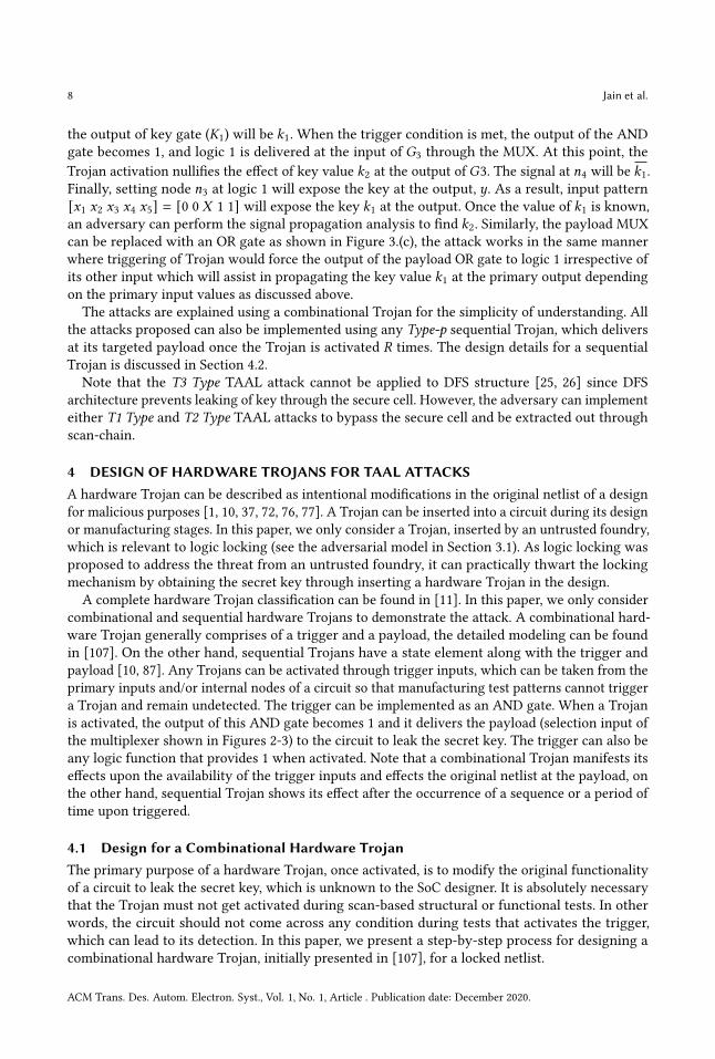
8 Jain et al.
the output of key gate (𝐾1) will be 𝑘1. When the trigger condition is met, the output of the ANDgate becomes 1, and logic 1 is delivered at the input of 𝐺3 through the MUX. At this point, theTrojan activation nullifies the effect of key value 𝑘2 at the output of 𝐺3. The signal at 𝑛4 will be 𝑘1.Finally, setting node 𝑛3 at logic 1 will expose the key at the output, 𝑦. As a result, input pattern[𝑥1 𝑥2 𝑥3 𝑥4 𝑥5] = [0 0 𝑋 1 1] will expose the key 𝑘1 at the output. Once the value of 𝑘1 is known,an adversary can perform the signal propagation analysis to find 𝑘2. Similarly, the payload MUXcan be replaced with an OR gate as shown in Figure 3.(c), the attack works in the same mannerwhere triggering of Trojan would force the output of the payload OR gate to logic 1 irrespective ofits other input which will assist in propagating the key value 𝑘1 at the primary output dependingon the primary input values as discussed above.
The attacks are explained using a combinational Trojan for the simplicity of understanding. Allthe attacks proposed can also be implemented using any Type-p sequential Trojan, which deliversat its targeted payload once the Trojan is activated 𝑅 times. The design details for a sequentialTrojan is discussed in Section 4.2.
Note that the T3 Type TAAL attack cannot be applied to DFS structure [25, 26] since DFSarchitecture prevents leaking of key through the secure cell. However, the adversary can implementeither T1 Type and T2 Type TAAL attacks to bypass the secure cell and be extracted out throughscan-chain.
4 DESIGN OF HARDWARE TROJANS FOR TAAL ATTACKSA hardware Trojan can be described as intentional modifications in the original netlist of a designfor malicious purposes [1, 10, 37, 72, 76, 77]. A Trojan can be inserted into a circuit during its designor manufacturing stages. In this paper, we only consider a Trojan, inserted by an untrusted foundry,which is relevant to logic locking (see the adversarial model in Section 3.1). As logic locking wasproposed to address the threat from an untrusted foundry, it can practically thwart the lockingmechanism by obtaining the secret key through inserting a hardware Trojan in the design.
A complete hardware Trojan classification can be found in [11]. In this paper, we only considercombinational and sequential hardware Trojans to demonstrate the attack. A combinational hard-ware Trojan generally comprises of a trigger and a payload, the detailed modeling can be foundin [107]. On the other hand, sequential Trojans have a state element along with the trigger andpayload [10, 87]. Any Trojans can be activated through trigger inputs, which can be taken from theprimary inputs and/or internal nodes of a circuit so that manufacturing test patterns cannot triggera Trojan and remain undetected. The trigger can be implemented as an AND gate. When a Trojanis activated, the output of this AND gate becomes 1 and it delivers the payload (selection input ofthe multiplexer shown in Figures 2-3) to the circuit to leak the secret key. The trigger can also beany logic function that provides 1 when activated. Note that a combinational Trojan manifests itseffects upon the availability of the trigger inputs and effects the original netlist at the payload, onthe other hand, sequential Trojan shows its effect after the occurrence of a sequence or a period oftime upon triggered.
4.1 Design for a Combinational Hardware TrojanThe primary purpose of a hardware Trojan, once activated, is to modify the original functionalityof a circuit to leak the secret key, which is unknown to the SoC designer. It is absolutely necessarythat the Trojan must not get activated during scan-based structural or functional tests. In otherwords, the circuit should not come across any condition during tests that activates the trigger,which can lead to its detection. In this paper, we present a step-by-step process for designing acombinational hardware Trojan, initially presented in [107], for a locked netlist.
ACM Trans. Des. Autom. Electron. Syst., Vol. 1, No. 1, Article . Publication date: December 2020.
TAAL: Tampering Attack on Any Key-based Logic Locked Circuits 9
x3
x5
x2
x1
x4
1
0y
kG1
G2
G3
G4
TT
k
Hardware Trojan activation pattern (HTAP)
SAF test patterns (P)
n1
n2
n4
n3
n5
MUX
(P)
X
0
011
0
P7 P6 P5 P4 P3 P2 P1
1 0 0 1 0 1 11 0 1 1 0 0 10 1 1 0 0 0 11 1 0 0 1 0 11 1 1 0 1 1 11 1 1 1 1 0 1
k
x1
x2
x3
x4
x5
X
0
011
0
P7 P6 P5 P4 P3 P2 P1
1 0 0 1 0 1 11 0 1 1 0 0 10 1 1 0 0 0 11 1 0 0 1 0 11 1 1 0 1 1 11 1 1 1 1 0 1
k
x1
x2
x3
x4
x5
(a) (b)
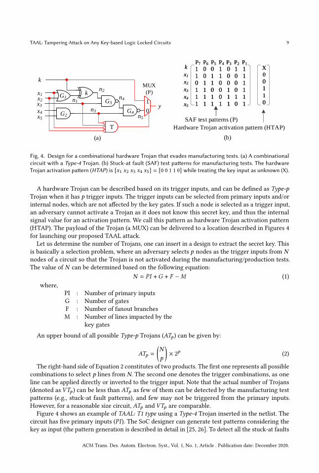
Fig. 4. Design for a combinational hardware Trojan that evades manufacturing tests. (a) A combinationalcircuit with a Type-4 Trojan. (b) Stuck-at fault (SAF) test patterns for manufacturing tests. The hardwareTrojan activation pattern (HTAP) is [𝑥1 𝑥2 𝑥3 𝑥4 𝑥5] = [0 0 1 1 0] while treating the key input as unknown (X).
A hardware Trojan can be described based on its trigger inputs, and can be defined as Type-pTrojan when it has p trigger inputs. The trigger inputs can be selected from primary inputs and/orinternal nodes, which are not affected by the key gates. If such a node is selected as a trigger input,an adversary cannot activate a Trojan as it does not know this secret key, and thus the internalsignal value for an activation pattern. We call this pattern as hardware Trojan activation pattern(HTAP). The payload of the Trojan (a MUX) can be delivered to a location described in Figures 4for launching our proposed TAAL attack.
Let us determine the number of Trojans, one can insert in a design to extract the secret key. Thisis basically a selection problem, where an adversary selects 𝑝 nodes as the trigger inputs from 𝑁
nodes of a circuit so that the Trojan is not activated during the manufacturing/production tests.The value of 𝑁 can be determined based on the following equation:
𝑁 = 𝑃𝐼 +𝐺 + 𝐹 −𝑀 (1)where,
PI : Number of primary inputsG : Number of gatesF : Number of fanout branchesM : Number of lines impacted by the
key gates
An upper bound of all possible Type-p Trojans (𝐴𝑇𝑝 ) can be given by:
𝐴𝑇𝑝 =
(𝑁
𝑝
)× 2𝑝 (2)
The right-hand side of Equation 2 constitutes of two products. The first one represents all possiblecombinations to select p lines from N. The second one denotes the trigger combinations, as oneline can be applied directly or inverted to the trigger input. Note that the actual number of Trojans(denoted as 𝑉𝑇𝑝 ) can be less than 𝐴𝑇𝑝 as few of them can be detected by the manufacturing testpatterns (e.g., stuck-at fault patterns), and few may not be triggered from the primary inputs.However, for a reasonable size circuit, 𝐴𝑇𝑝 and 𝑉𝑇𝑝 are comparable.Figure 4 shows an example of TAAL: T1 type using a Type-4 Trojan inserted in the netlist. The
circuit has five primary inputs (𝑃𝐼 ). The SoC designer can generate test patterns considering thekey as input (the pattern generation is described in detail in [25, 26]. To detect all the stuck-at faults
ACM Trans. Des. Autom. Electron. Syst., Vol. 1, No. 1, Article . Publication date: December 2020.

10 Jain et al.
(SAFs), seven test patterns (e.g., 𝑃 = {𝑃1, 𝑃2, . . . , 𝑃7}) are required and they are generated usingSynopsys TetraMax [75] ATPG tool. To avoid a Trojan being activated by these manufacturing testpatterns, the Trojan’s trigger must remain quiet for all these input patterns. A hardware Trojanactivation pattern is selected, where 𝐻𝑇𝐴𝑃 = (𝑋 0 0 1 1 0)𝑇 ∉ 𝑃 . As the logic values of nodes 𝑛2,𝑛4, and 𝑛5 are impacted by the key, 𝑘 , these nodes are excluded in designing the Trojan. If one ofthese nodes is selected, an adversary may not activate the trigger as it does not know the key value.The upper bound of all possible Type-4 Trojans (𝐴𝑇4) can be given by:
𝐴𝑇4 =
(74
)× 24 = 560 (3)
where, 𝑁 = 5 + 5 − 3 = 7.Out of these 560 possible Trojans, 188 will be detected by the test patterns 𝑃 . The remaining 372
will be treated as valid Trojans, and an adversary can select one of them. In Figure 4, 𝑥1, 𝑥2, 𝑥3 and𝑛3 are selected as the trigger. Similarly, one can also design other types (Type-1 through Type-6) ofTrojans to launch TAAL attacks. Note that the Trojan needs to be quiet during normal operationsso that no functional errors are observed at the primary output. An adversary can select rare nodes,whose value do not become identical with trigger pattern very often under continuous/normaloperation of the IC, for the trigger inputs while designing a Trojan. One can perform controllability,and observability analysis [13] to find such rare nodes, and then select them as the trigger inputs.However, we do not include such analysis, as including rare nodes in the trigger for a sequentialhardware Trojan is not a hard requirement. In this paper, a sequential Trojan is modeled using acombinational Trojan that needs to be triggered 𝑅 times consecutively.
Algorithm 1: Design of Type-𝑝 Trojaninput : Locked Netlist (𝐶), test pattern set (𝑃 ), Type-p Trojanoutput : Hardware Trojan activation pattern (HTAP), Trigger inputs (𝑇 )
1 Read the locked netlist (𝐶);2 Read production test patterns (𝑃 );3 Perform logic simulation using 𝑃 to form a matrix (𝐴) of all the internal node values;4 Select a hardware Trojan activation pattern (𝐻𝑇𝐴𝑃 ), where 𝐻𝑇𝐴𝑃 ∉ 𝑃 ;5 Perform logic simulation using 𝐻𝑇𝐴𝑃 and form a matrix (𝐻 ) of all the internal node values;6 Select 𝑝 random nodes that are not affected by the key gates of C for the trigger inputs;7 Construct a new matrix 𝐴𝑝 that corresponds to the trigger locations for all test patterns;8 Construct a new vector 𝐻𝑝 that corresponds to the trigger locations for 𝐻𝑇𝐴𝑃 ;9 if 𝐻𝑝 ∉ 𝐴𝑝 then10 Choose selected 𝑝 nodes as trigger, 𝑇 ;11 else12 Discard selected 𝑝 nodes, as it would activate the Trojan during tests;13 Go to Step 6;14 end15 Report 𝐻𝑇𝐴𝑃 and 𝑇 ;
An automated process is developed to design a combinational hardware Trojan. Algorithm1 provides steps to be followed for designing a Type-p Trojan that eludes activation during themanufacturing test. The inputs of the algorithm are locked netlist(𝐶),𝑀 production/manufacturing
ACM Trans. Des. Autom. Electron. Syst., Vol. 1, No. 1, Article . Publication date: December 2020.

TAAL: Tampering Attack on Any Key-based Logic Locked Circuits 11
x3
x5
x2
x1
x4
1
0y
kG1
G2
G3
G4
TT
k
n1
n2
n4
n3
n5
MUX
(P)
R-bit
Counter
en
clk
(a) (b)
S0
S1
S2
SR-1
en/0
en/0
en/0
en/0
en/0
en/1
en/0
en/0
en/0
Fig. 5. (a) The netlist of a sequential Trojan with a R-bit counter, (b) The finite state machine (FSM) of thecounter used in a sequential Trojan.
test patterns (𝑃 = {𝑃1, 𝑃2, . . . , 𝑃𝑀 }) and the Trojan type (𝑝). The algorithm results in the hardwareTrojan activation pattern (HTAP) and the trigger inputs. Initially, it reads the Trojan-free lockednetlist (𝐶) and the set of manufacturing test patterns (𝑃 ) (Lines 1-2). Logic simulation is performedusing these patterns, and store the internal node values in a matrix, 𝐴 (Line 3). It is unnecessary tostore the nodes that are impacted by the key gates, as their values will be unknown (Xs) during thesimulation. Note that 𝐴 is a 𝑁 ×𝑀 matrix. A hardware Trojan activation pattern of an adversary’schoice is selected (Line 4). Similarly, matrix 𝐻 is formed due to logic simulation using HTAP (Line5). Here, 𝐻 is a 𝑁 × 1 vector. To select the trigger inputs, one can select 𝑝 random nodes that are notaffected by the key gates of the locked circuit (Line 6). To perform the search whether the triggervalues are presented in the production set, the matrix 𝐴𝑝 and vector 𝐻𝑝 are constructed (Lines7-8). If 𝐻𝑝 is not in 𝐴𝑝 , the trigger (𝑇 ) is selected (Line 10), otherwise, drop the selected 𝑝 locationsas the Trojan will be activated during the production tests (Lines 12-13) and new 𝑝 locations areselected (Line 6). Finally, the algorithm reports 𝐻𝑇𝐴𝑃 and 𝑇 (Line 15).
4.2 Design for a Sequential Hardware TrojanA sequential Trojan modifies the functionality of a circuit until a specified time has elapsed afterthe trigger condition is satisfied. However, in this paper, we designed a sequential Trojan that needsto be triggered 𝑅 times to deliver the payload. We designed a sequential Trojan in this way so thatit can be modeled using a combinational Trojan, described in detail in the previous section.A sequential Trojan also consists of a trigger and payload similar to a combinational Trojan.
Additionally, the trigger part contains state elements that ascertain the payload in future time. Inour sequential Trojan design, a R-bit counter is implemented as the state elements. This counter isenabled (𝑒𝑛) once the trigger condition is fulfilled, i.e., the output of the p-input AND gate becomes 1.The counter increments by one unit, every-time the Trojan is triggered using the Trojan activationpattern (HTAP). The Trojan delivers at the payload (MUX) only after reaching the maximum countvalue (𝑅). The circuit tampered with Sequential Trojan will show the intended malfunction, keyextraction in TAAL attacks, only upon applying the activation pattern successively R-times to thecircuit.Figure 5.(a) shows the TAAL attack using a sequential Trojan. The trigger consists of a 𝑝-input
AND gate and a 𝑅-bit counter. The finite-state machine (FSM) of the counter is shown in Figure 5.(b).
ACM Trans. Des. Autom. Electron. Syst., Vol. 1, No. 1, Article . Publication date: December 2020.

12 Jain et al.
The FSM goes to the next states when 𝑒𝑛 = 1; otherwise, it returns to the initial state, 𝑆0. The counterproduces an output of 1, once 𝑒𝑛 is hold to 1 consecutively 𝑅 clock cycles, as it takes (𝑅−1) cycles toreach 𝑆𝑅−1. Note that this sequential Trojan can be modeled as R number of combinational Trojans.An adversary can also design a different sequential Trojan, already in the literature, to launch theTAAL attack. The sequential Trojan increases the complexity compared to a combinational Trojanas it manifests its effect to the payload only after the sequence of repeated application of triggerinputs. Only the adversary has the knowledge regarding the maximum counter value making itvery difficult for detection.
Note that the Trojan flip-flops (FFs) cannot be a part of the scan chain, since a Trojan is implantedafter the test pattern generation (if this process is performed at the design house). Any modificationsin the scan chain will be detected with a stuck-at fault test. As the Trojan circuitry is extremelysmall (one counter and AND gate for the Trigger), it is possible to verify the proper operationusing a functional test (i.e., applying the Trigger pattern 𝑅 times and observe the response). Thereis no need to add Trojan FFs in the scan chain and perform scan tests. Now, one can argue thattest patterns are generated at the foundry, and Trojan FFs are a part of the scan chain. In such asituation, the scan shift will not change the state of the original FFs in the circuit. However, it ishighly unlikely that an adversary will add these malicious FFs in the scan chains, as one can easilyfind the response of the combinational part of the Trojan and determine tampering.
4.3 Design for an Analog/RF TrojanAnalog Trojans [39, 48, 96] can also be used to launch different TAAL attacks. In this section, weprovide a brief description of different analog Trojans. The payload can be implemented using amultiplexer or an OR gate (see Figures 2-3) like a combinational or sequential hardware Trojan.The implementation of the trigger, however, be different depending on the Trojan design. Theanalog or RF-leaking Trojans can detect an extremely rare event with just a handful of transistorsadded to the circuit. Moreover, analog techniques and characteristics to design the stealthy triggerfor Trojans are usually difficult to uncover due to their small footprint [96]. The authors used theswitched capacitor to design a trigger circuit, which is activated when the frequency of toggling ona victim wire goes above a certain threshold. When the wire toggles frequently, charge accumulateson the capacitor faster than it leaks away, eventually the voltage of the capacitor rises above thethreshold. This deploys the payload to cause intentional malicious activity. A similar notion isutilized to introduce triggers that are activated after some delay or operate on a specific voltagethreshold [48]. Kison et al. exploited the capacitor coupling in sub-micron process technologiesto design Trojans [39]. This technique uses rerouting and extending existing layout tracks toincrease the capacitive coupling between a victim and an aggressor wire in a way that a low to hightransition on the aggressor can adequately affect the victim wire and flip its digital value. Similarly,RF-leaking Trojans leak the information through the Trojan-induced channel without affecting thelegitimate signal/channel [18, 73].
5 ANALYSISThe hardware Trojans presented in Section 4 pose a unique challenge to the SoC designers forsecuring their designs.
5.1 Complexity AnalysisIn this section, we show that an adversary can implement a Trojan in a very large number of ways,and it is practically infeasible to detect all of them with absolute certainty. We choose six benchmarkcircuits from ISCAS’85 benchmark suites [12] to show the complexity of Trojan detection even forthese small benchmark circuits.
ACM Trans. Des. Autom. Electron. Syst., Vol. 1, No. 1, Article . Publication date: December 2020.

TAAL: Tampering Attack on Any Key-based Logic Locked Circuits 13
Table 1. Circuit parameters.
Benchmarks # Gates Key Size(|𝐾 |)
# TotalLines(𝑁 +𝑀)
# NetLines (𝑁 )
# TestPatterns
Faultcoverage
C432 160 30 349 233 58 100%C499 202 30 491 226 78 100%C880 383 30 594 350 86 100%C1908 880 30 552 223 83 100%C3540 1669 83 1826 1114 173 100%C6288 2416 128 5621 1335 77 100%
Table 1 shows the design details for different locked benchmark circuits. The number of logicgates and key size for these circuits is shown in Columns 2 and 3. The number of key bits is selectedin such a way that the total area overhead does not exceed 5%. However, for industrial designwith millions of gates, the key gates will merely add any overhead. Column 4 represents the totalnumber of nets in these circuits (see Equation 1). The number of nets that are not affected by keygates is shown in Column 5. A key gate is selected by analyzing the netlist and forward tracingis performed till the primary output(s) is reached. Simultaneously, removing all the nodes thatbelongs to these paths from the overall list of 𝑁 +𝑀 . Note that this includes any fanout branchesas well while performing forward tracing. This step is repeated for all the key gates to get thenodes that are not impacted by the key values. Note that these nets cannot be selected for triggerinputs. The manufacturing test patterns are generated using Synopsys TetraMax Automatic TestPattern Generation (ATPG) tool [75] with targeted 100% fault coverage (Columns 6-7). For the C432benchmark, we insert 30 key gates randomly in the netlist with 160 logic gates. There are 349 netsin the netlist, out of which 233 nets can be selected for the Trojan trigger as the remaining nets areaffected by the key gates. The TetraMax ATPG tool generates 58 stuck-at fault patterns and reports100% fault coverage. An adversary will use these test patterns to design the Trojans such that theyare not activated during the manufacturing tests. A similar analysis can be performed for all otherbenchmark circuits through the details mentioned in respective rows.
Table 2. Number of hardware Trojans for launching TAAL attacks.
Benchmarks Type-2 Trojan Type-3 Trojan Type-4 Trojan𝑨𝑻2 𝑽𝑻2 𝑨𝑻3 𝑽𝑻3 𝑨𝑻4 𝑽𝑻4
C432 1.08 × 10⁵ 1.04 × 10⁵ 1.66 × 10⁷ 1.43 × 10⁷ 1.91 × 10⁹ 1.34 × 10⁹C499 1.02 × 10⁵ 0.27 × 10⁵ 1.52 × 10⁷ 2.11 × 10⁶ 1.69 × 10⁹ 1.21 × 10⁸C880 2.44 × 10⁵ 2.25 × 10⁵ 5.67 × 10⁷ 4.80 × 10⁷ 9.83 × 10⁹ 7.35 × 10⁹C1908 0.99 × 10⁵ 0.96 × 10⁵ 1.46 × 10⁷ 1.33 × 10⁷ 1.60 × 10⁹ 1.27 × 10⁹C3540 2.48 × 10⁶ 2.35 × 10⁶ 1.84 × 10⁹ 1.57 × 10⁹ 1.02× 10¹² 0.74× 10¹²C6288 3.56 × 10⁶ 3.50 × 10⁶ 3.17 × 10⁹ 3.00 × 10⁹ 2.11× 10¹² 1.82× 10¹²
Table 2 shows the number of combinational hardware Trojans that can be designed to performTAAL attacks (mentioned in Section 3) for different benchmark circuits. The upper bound (seeEquation 2) for all possible Trojans that can be inserted in the circuit is denoted in Column 2, 4, and6. Out of all possible Trojans, the valid Trojans that will not be detected during manufacturing testsare shown in Columns 3, 5, and 7. For C432 benchmark circuit, the total number of Type-2 Trojans
ACM Trans. Des. Autom. Electron. Syst., Vol. 1, No. 1, Article . Publication date: December 2020.

14 Jain et al.
is 1.08 × 10⁵, whereas, the number of valid Trojans is 1.0 × 10⁵. The number of Trojans increasesexponentially with the increase of the Trojan type (𝑝). Note that 𝐴𝑇𝑝 and𝑉𝑇𝑝 are in the same order,which gives an adversary to select a Trojan of its choice from a large collection. It is worthwhileto mention that an adversary needs to choose a Trojan whose triggers are selected from the rarenodes such that it does not get activated during normal operation. However, it is not necessary toimpose this condition for designing a sequential Trojan, as it is highly unlikely that a particulartrigger condition will arrive 𝑅 times consecutively during the normal operation of a chip.Note that the result in Table 2 does not show the complexity for sequential hardware Trojans
as the ISCAS’85 benchmark circuits are combinational in nature. This table is intended to showthe number of possible combinational Trojans, resulted from an effective 𝑁 number of nets. Onecan easily extend the results for industrial designs, where an adversary can insert any type ofcombinational, sequential, or analog Trojans to perform a TAAL attack. Note that we choose smallISCAS’85 benchmark circuits instead of larger benchmarks (e.g., opencores) to demonstrate thedifficulty of detecting all the Trojans even for smaller circuits. It is obvious to infer that the difficultywill increase for larger circuits. The number of all possible valid Trojans is in the order of 1012,which is so large even for a small benchmark circuit, C6288, with 2416 gates, when considering onlyfour trigger inputs. If we show that detecting all possible valid Trojans for a very small benchmarkis a complex problem, it will be sufficient to maintain that complexity for large circuits.
5.2 Overhead AnalysisThe area for a hardware Trojan can be varied based on the trigger inputs. A Type-p combinationalTrojan consists of an AND gate with p-trigger inputs and a multiplexer or an OR gate as payload.For a sequential Trojan, it is necessary to add a 𝑅-bit counter along with a 𝑝-input AND gate toimplement the trigger. This subsection presents the area and power overhead for different ITC’99benchmark circuits [22] locked with a 128-bit key. The simulation is performed by using Synopsysdesign compiler [23] with 32nm technology [50]. A single sequential hardware Trojan of Type-2 toType-4 is added to each benchmark circuits for launching the T3 Type TAAL attack. The output ofa single trigger is routed to 128 payload locations (OR gates). This is the worst-case area overhead,as we often need less than 128 OR gates to expose all the 128 key bits. For example, shown inFigure 3.(c), we need only one OR gate to determine two key bits (e.g., 𝐾1 and 𝐾2). For a givenbenchmark circuit, 𝐴𝑂 represents the original circuit area, whereas 𝐴𝑇 represents the area of itsTrojan inserted version. The area overhead (𝐴𝑂) is computed using the following formula:
𝐴𝑂 =𝐴𝑇 −𝐴𝑂
𝐴𝑂
× 100% (4)
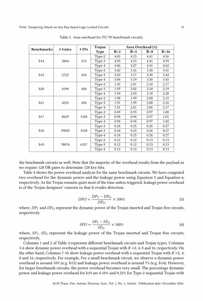
Table 3 shows the area overhead analysis for different ITC’99 benchmark circuits. The numberof logic gates and flip-flops (FFs) for each synthesized benchmark circuits are shown in Columns 2and 3, respectively. The Type of Trojan is represented in Column 4. It follows the same definitionof Type-p Trojan, where 𝑝 represents the number of trigger inputs. Columns 5 to 8 indicate thepercentage area overhead (computed using Equation 4). The Trojan consists of a counter and aAND gate as the trigger, and 128 OR gate as the payload. The 𝑅 represents the maximum count forthe counter. For example, 𝑅 = 8 means that the trigger has a maximum count of 8.We observe an area overhead of less than 5% (e.g. b14 with only 2064 gates and 215 FFs) for a
small benchmark circuit. However, it becomes significantly small for larger benchmark circuits.Considering b19, the percentage area overhead is 0.13% for Type-2 sequential Trojan with 𝑅 = 8.The area overhead remains almost constant even with an increased count (e.g. 𝑅 = 16) anddifferent Trojan Types for a large benchmark circuit. A similar analysis can be performed for all
ACM Trans. Des. Autom. Electron. Syst., Vol. 1, No. 1, Article . Publication date: December 2020.
TAAL: Tampering Attack on Any Key-based Logic Locked Circuits 15
Table 3. Area overhead for ITC’99 benchmark circuits.
Benchmarks # Gates # FFs TrojanType
Area Overhead (%)R=2 R=4 R=8 R=16
b14 2064 215Type-2 4.03 4.23 4.41 4.56Type-3 4.05 4.23 4.41 4.59Type-4 4.06 4.27 4.41 4.62
b15 2722 418Type-2 3.02 3.16 3.30 3.41Type-3 3.03 3.17 3.30 3.43Type-4 3.04 3.19 3.30 3.45
b20 4190 430Type-2 1.92 2.01 2.10 2.17Type-3 1.93 2.02 2.10 2.19Type-4 1.94 2.03 2.10 2.20
b21 4225 430Type-2 1.90 1.99 2.08 2.15Type-3 1.91 1.99 2.08 2.16Type-4 1.91 2.01 2.06 2.17
b17 8629 1328Type-2 0.89 0.93 0.97 1.00Type-3 0.90 0.94 0.97 1.01Type-4 0.90 0.94 0.97 1.02
b18Type-2 0.24 0.25 0.26 0.27
39845 3168 Type-3 0.24 0.25 0.26 0.27Type-4 0.24 0.25 0.26 0.27
b19Type-2 0.12 0.12 0.13 0.13
78076 6337 Type-3 0.12 0.12 0.13 0.13Type-4 0.12 0.12 0.13 0.13
the benchmark circuits as well. Note that the majority of the overhead results from the payload aswe require 128 OR gates to determine 128 key bits.
Table 4 shows the power overhead analysis for the same benchmark circuits. We have computedtwo overhead for the dynamic power and the leakage power using Equation 5 and Equation 6,respectively. As the Trojan remains quiet most of the time unless triggered, leakage power overheadis of the Trojan designers’ concern so that it evades detection.
𝐷𝑃𝑂 =𝐷𝑃𝑇 − 𝐷𝑃𝑂
𝐷𝑃𝑂× 100% (5)
where, 𝐷𝑃𝑇 and 𝐷𝑃𝑂 represent the dynamic power of the Trojan inserted and Trojan free circuits,respectively.
𝑆𝑃𝑂 =𝑆𝑃𝑇 − 𝑆𝑃𝑂
𝑆𝑃𝑂× 100% (6)
where, 𝑆𝑃𝑇 , 𝑆𝑃𝑂 represent the leakage power of the Trojan inserted and Trojan free circuits,respectively.Columns 1 and 2 of Table 4 represent different benchmark circuits and Trojan types. Columns
3-6 show dynamic power overhead with a sequential Trojan with 𝑅 =2, 4, 8 and 16, respectively. Onthe other hand, Columns 7-10 show leakage power overhead with a sequential Trojan with 𝑅 =2, 4,8 and 16, respectively. For example, For a small benchmark circuit, we observe a dynamic poweroverhead is around 10% (e.g. b15) and leakage power overhead is around 7% (e.g. b14). However,for larger benchmark circuits, the power overhead becomes very small. The percentage dynamicpower and leakage power overhead for b19 are 0.10% and 0.22% for Type-2 sequential Trojan with
ACM Trans. Des. Autom. Electron. Syst., Vol. 1, No. 1, Article . Publication date: December 2020.

16 Jain et al.
Table 4. Power overhead for benchmark circuits.
Benchmarks TrojanTypes
Dynamic Power Overhead (%) Leakage Power Overhead (%)R=2 R=4 R=8 R=16 R=2 R=4 R=8 R=16
b14Type-2 9.61 8.46 8.63 8.86 6.02 6.63 6.89 7.05Type-3 9.70 8.34 8.60 8.80 5.91 6.62 6.77 7.03Type-4 9.63 8.38 8.52 8.70 5.95 6.64 6.82 7.05
b15Type-2 10.22 8.99 9.18 9.42 4.78 5.27 5.48 5.60Type-3 10.31 8.87 9.14 9.36 4.69 5.26 5.37 5.58Type-4 10.24 8.90 9.05 9.24 4.73 5.28 5.42 5.60
b20Type-2 7.42 6.53 6.67 6.84 3.01 3.32 3.45 3.53Type-3 7.49 6.44 6.64 6.80 2.96 3.31 3.39 3.52Type-4 7.44 6.47 6.58 6.71 2.98 3.33 3.41 3.53
b21Type-2 7.67 6.75 6.89 7.07 2.99 3.30 3.43 3.51Type-3 7.74 6.66 6.86 7.03 2.94 3.29 3.36 3.49Type-4 7.69 6.68 6.80 6.94 2.96 3.30 3.39 3.51
b17Type-2 3.36 2.96 3.02 3.10 1.52 1.67 1.74 1.78Type-3 3.39 2.92 3.01 3.08 1.49 1.67 1.71 1.77Type-4 3.37 2.93 2.98 3.04 1.50 1.68 1.72 1.78
b18Type-2 0.24 0.21 0.21 0.22 0.38 0.42 0.44 0.45Type-3 0.24 0.21 0.21 0.22 0.37 0.42 0.43 0.44Type-4 0.24 0.21 0.21 0.21 0.38 0.42 0.43 0.45
b19Type-2 0.12 0.10 0.11 0.11 0.20 0.22 0.22 0.23Type-3 0.12 0.10 0.11 0.11 0.19 0.21 0.22 0.23Type-4 0.12 0.10 0.10 0.11 0.19 0.22 0.22 0.23
R=4, respectively. Note that for a large circuit, an increased count (e.g. R=16) and different Types ofa Trojan will not have a significant impact on dynamic power and leakage power overhead.
6 FUTURE RESEARCH DIRECTION FOR SECURE LOGIC LOCKINGThe security of a logic locking technique can be tied together with the hardware Trojan detectionproblem. Developing a SAT-registrant logic locking is not sufficient enough to prevent IC overpro-duction or to protect IPs. It is required to address the detection of Trojans inserted at an untrustedmanufacturing site. Researchers have already proposed different techniques to detect and preventhardware Trojans. The detection methods can be grouped into two different categories, such as,logic testing [8, 17, 28, 42, 84], and side-channel analysis [3, 6, 7, 43, 45, 54]. On the other hand,prevention methods can be categorized as design-for-trust measures [16, 49, 57, 64, 91] and splitmanufacturing [61, 81, 89].Logic testing by applying stimuli to primary inputs (PIs) and observe responses at primary
outputs (POs) can be used to detect these Trojans [8, 10, 17, 28, 42, 70]. The decision is beingmade whether a chip is tampered with a hardware Trojan by observing a mismatch between theobserved and expected responses. Note that the accuracy of the detection process does not dependon the manufacturing process variations. However, the detection will be extremely difficult as it ispractically impossible to detect all types of combinational Trojans. In addition, it is not feasible totrigger a sequential Trojan, as it requires to apply the same trigger pattern at the input 𝑅 times.Side-channel information, such as, power [90], temperature [51], delay [34], and radiation [29]
can be used to detect a hardware Trojan. The side-channel fingerprinting technique for detectingAnalog/RF hardware Trojans in a wireless cryptographic IC has also been proposed [35, 46]. These
ACM Trans. Des. Autom. Electron. Syst., Vol. 1, No. 1, Article . Publication date: December 2020.

TAAL: Tampering Attack on Any Key-based Logic Locked Circuits 17
detection methods rely on the availability of Trojan-free golden circuits for creating Trojan freesignature. It can be very difficult to acquire a golden sample as all the chips may have Trojans. Pathdelay-based testing has limitations on detecting a hardware Trojan as long as the Trojan is inactive.Note that activating a Trojan is challenging as an adversary can select a hard to activate Trojan. Inaddition, the path delay does not depend on the size of the trigger circuit or the number of payloadsattached with each trigger as the Trojan remains quiet during the logic testing. In addition, processand environmental variations may mask the side-channel leakage, when a Trojan circuitry is small.
While dedicated towards hardware Trojan detection, researchers propose different measures toprevent a Trojan from being inserted into the design in the first place. These solutions involvedcharacterization of ring-oscillator [57], shadow registers [43], and delay elements [62] to detect thedelay deviation caused by hardware Trojans. Reducing the rare signal in the circuitry is anotherproposed method for designers to reduce the risk of being implanted with a Trojan [64, 106].Camouflage fill techniques [20, 59] to create indistinguishable layouts for different gates by addingdummy contacts and connections can prevent the attacker from extracting a correct gate-levelnetlist of a circuit for Trojan insertion. Xiao et al. proposed to fill all the unused spaces using fillercells so that an untrusted foundry cannot insert a Trojan [69, 91]. However, this direction still lacksany firm solution as more emphasis is observed in Trojan detection.
Split Manufacturing can be an effective way to thwart Hardware Trojan insertion at an untrustedfoundry. In split manufacturing, the production of ICs is carried out in two different foundries[32]. The design is divided into two parts – Front End of Line (FEOL) and Back End of Line(BEOL). An untrusted foundry is provided with the FEOL design, which contains partial informationregarding the design that requires complex steps for fabricating and involves higher cost. Fabricationof BEOL does not incorporate complex fabrication steps and can be done by a smaller trustedfoundry. The untrusted foundry sends the fabricated wafers directly to the smaller foundry for thecomplete fabrication. This way the untrusted foundry can be restricted to make any Trojan basedmodification as it does not have the complete information regarding the design. However, severalattacks undermining the security achieved through split manufacturing have also been proposedin past [47, 88, 94].
Recent research contributions showed that machine learning and image processing can also beincorporated to detect hardware Trojans in the chip. Vashistha et al. presented Trojan scanner [83],which uses a trusted GDSII layout (golden layout) and scanning electron microscope (SEM) imagesto identify the malicious modifications made in the netlist during the manufacturing of a circuit. Aunique descriptor for each type of gate is prepared based on different features using computer visionalgorithms along with a machine-learning model of a golden layout and SEM images of an IC underauthentication. These descriptors, when compared to each other can detect any modifications eitherin the form of additional gates or modified gates which might raise the suspicion for a potentialhardware Trojan. Moreover, Trojan scanner also presents the trade-off between the accuracy andSEM parameters. The authors demonstrated the effectiveness of the scheme using a smart carddie as a test sample (generally manufactured with 90 nm technology). It is yet to be validated itseffectiveness of detection when a chip is fabricated using recent technology nodes (10 nm andbeyond).Research groups have also investigated vulnerabilities in the analog/RF front-end of a wireless
device that can facilitate hardware Trojan attacks. Subramani et al. proposed defense to distinguishbetween channel-induced and Trojan-induced impact on the legitimate signal through its traits [73].Acknowledging excessive toggling activity on a victim wire of Trojans such as A2 [96], Hou et al.proposed to add on-chip monitors to measure switching activity on potential victim wires duringan adjustable time period and raises an alarm if such activity goes above a certain threshold [30].This method can be effective for detecting A2 Trojan which comprises of a capacitor as a trigger.
ACM Trans. Des. Autom. Electron. Syst., Vol. 1, No. 1, Article . Publication date: December 2020.

18 Jain et al.
Reverse engineering based detection methods have also been proposed by sorting trace lengths torealize the minimum capacitance needed for such Trojans [27]. However, it is possible to mitigatethis requirement by an adversary, e.g. using multiple layers/higher voltages to evade detection bythis kind of approaches.Despite significant research have been performed on detecting hardware Trojans, we still lack
efficient and accurate methods for modeling them and generating tests for their detection. Oncethe detection of hardware Trojans is ensured, an SoC designer can choose a SAT-resistant logiclocking to prevent IC overproduction and IP piracy.
7 CONCLUSIONIn this paper, we have demonstrated the vulnerability of logic locking techniques through a set oftampering attacks with hardware Trojans. Three types of proposed TAAL attacks can defeat anylogic locking techniques that rely on storing the secret key in a tamper-proof memory. In T1 typeTAAL Attack, we showed how an adversary could extract the key from a locked netlist withoutknowing the details of the logic locking technique used to protect the circuit. For T2 type and T3type TAAL attacks, the complexity of detecting an attack has been improved. Only the attackerknows the specific values that can lead to key extraction, increasing the identification of a TAALattack. To launch a TAAL attack, we develop models for combinational and sequential hardwareTrojans. We also proposed an algorithm to design a hardware Trojan that cannot be detected bymanufacturing tests. The results depict the range of Trojans selected by an adversary, which has avery high order of magnitude. Finally, we describe relevant detection and avoidance strategies forhardware Trojans to make logic locking secure.
ACKNOWLEDGMENTThis work was supported in part by the National Science Foundation under grant number CNS-1755733, and the United States Air Force/Air Force Materiel Command (USAF/AFMC) under grantAF-FA8650-19-1-1707. Any opinions, findings, and conclusions or recommendations expressedin this material are those of the authors and do not necessarily reflect the views of the NSF andUSAF/AFMC.
REFERENCES[1] Sally Adee. 2008. The Hunt for the Kill Switch. IEEE Spectrum 45, 5 (2008), 34–39.[2] Age Yeh. 2012. Trends in the global IC design service market. DIGITIMES Research.[3] Dakshi Agrawal, Selcuk Baktir, Deniz Karakoyunlu, Pankaj Rohatgi, and Berk Sunar. 2007. Trojan Detection Using IC
Fingerprinting. In Proc. IEEE Symp. Security and Privacy (SP). 296–310.[4] Yousra Alkabani and Farinaz Koushanfar. 2007. Active Hardware Metering for Intellectual Property Protection and
Security.. In USENIX security symposium. 291–306.[5] Yousra Alkabani, Farinaz Koushanfar, and Miodrag Potkonjak. 2007. Remote activation of ICs for piracy prevention
and digital right management. In Proc. of IEEE/ACM int. conf. on Computer-aided design. 674–677.[6] Mainak Banga and Michael S Hsiao. 2008. A Region Based Approach for the Identification of Hardware Trojans. In
Proc. IEEE Int. Workshop on Hardware-Oriented Security and Trust. 40–47.[7] Mainak Banga and Michael S Hsiao. 2009. A Novel Sustained Vector Technique for the Detection of Hardware Trojans.
In Proceedings of International Conference VLSI Design. 327–332.[8] Mainak Banga and Michael S Hsiao. 2011. Odette: A Non-Scan Design-for-Test Methodology for Trojan Detection in
ICs. In Proc. IEEE Int. Symp. Hardware-Oriented Security and Trust. 18–23.[9] Alex Baumgarten, Akhilesh Tyagi, and Joseph Zambreno. 2010. Preventing IC piracy using reconfigurable logic
barriers. IEEE Design & Test of Computers 27, 1 (2010), 66–75.[10] Swarup Bhunia, Michael S Hsiao, Mainak Banga, and Seetharam Narasimhan. 2014. Hardware Trojan Attacks: Threat
Analysis and Countermeasures. Proc. IEEE 102, 8 (2014), 1229–1247.[11] Swarup Bhunia and Mark Tehranipoor. 2018. Hardware Security: A Hands-on Learning Approach. Morgan Kaufmann.[12] David Bryan. 1985. The ISCAS’85 benchmark circuits and netlist format. North Carolina State University 25 (1985).
ACM Trans. Des. Autom. Electron. Syst., Vol. 1, No. 1, Article . Publication date: December 2020.

TAAL: Tampering Attack on Any Key-based Logic Locked Circuits 19
[13] Michael Bushnell and Vishwani Agrawal. 2004. Essentials of electronic testing for digital, memory and mixed-signalVLSI circuits. Vol. 17. Springer Science & Business Media.
[14] Encarnacin Castillo, Uwe Meyer-Baese, Antonio García, Luis Parrilla, and Antonio Lloris. 2007. IPP@ HDL: efficientintellectual property protection scheme for IP cores. IEEE Transactions on Very Large Scale Integration (VLSI) Systems15, 5 (2007), 578–591.
[15] Rajat Subhra Chakraborty and Swarup Bhunia. 2008. Hardware protection and authentication through netlist levelobfuscation. In Proc. of IEEE/ACM International Conference on Computer-Aided Design. 674–677.
[16] Rajat Subhra Chakraborty and Swarup Bhunia. 2009. Security Against Hardware Trojan Through a Novel Applicationof Design Obfuscation. In Proc. Int. Conf. Computer-Aided Design. 113–116.
[17] Rajat Subhra Chakraborty, Francis G Wolff, Somnath Paul, Christos A Papachristou, and Swarup Bhunia. 2009. MERO:A Statistical Approach for Hardware Trojan Detection. In Proc. International Workshop on Cryptographic Hardwareand Embedded Systems (CHES). 396–410.
[18] Doohwang Chang, Bertan Bakkaloglu, and Sule Ozev. 2015. Enabling unauthorized RF transmission below noisefloor with no detectable impact on primary communication performance. In VLSI Test Symposium (VTS). 1–4.
[19] Edoardo Charbon. 1998. Hierarchical watermarking in IC design. In Proc. of the Custom Integrated Circuits. 295–298.[20] Ronald P Cocchi, James P Baukus, Lap Wai Chow, and Bryan J Wang. 2014. Circuit camouflage integration for
hardware IP protection. In Proceedings of Annual Design Automation Conference. 1–5.[21] Gustavo K Contreras, Md Tauhidur Rahman, and Mohammad Tehranipoor. 2013. Secure split-test for preventing IC
piracy by untrusted foundry and assembly. In IEEE International symposium on defect and fault tolerance in VLSI andnanotechnology systems (DFTS). 196–203.
[22] Scott Davidson. 1999. ITC’99 benchmark circuits-preliminary results. In International Test Conference 1999. Proceedings(IEEE Cat. No. 99CH37034). IEEE Computer Society, 1125–1125.
[23] DC Ultra: Concurrent Timing, Area, Power, and Test Optimization. 2019. [Online] Available at:https://www.synopsys.com/implementation-and-signoff/rtl-synthesis-test/dc-ultra.html.
[24] Ujjwal Guin, Qihang Shi, Domenic Forte, and Mark M Tehranipoor. 2016. FORTIS: a comprehensive solution forestablishing forward trust for protecting IPs and ICs. ACM Transactions on Design Automation of Electronic Systems(TODAES) 21, 4 (2016), 63.
[25] U. Guin, Ziqi Zhou, and A. Singh. 2017. A novel design-for-security (DFS) architecture to prevent unauthorized ICoverproduction. In Proc. of the IEEE VLSI Test Symposium (VTS). 1–6.
[26] Ujjwal Guin, Ziqi Zhou, and Adit Singh. 2018. Robust design-for-security architecture for enabling trust in ICmanufacturing and test. Trans. on Very Large Scale Integration (VLSI) Systems 26, 5 (2018), 818–830.
[27] Xiaolong Guo, Huifeng Zhu, Yier Jin, and Xuan Zhang. 2019. When Capacitors Attack: Formal Method Driven Designand Detection of Charge-Domain Trojans. In Design, Automation & Test in Europe Conf. & Exhibition (DATE).
[28] Syed Kamran Haider, Chenglu Jin, Masab Ahmad, Devu Shila, Omer Khan, and Marten van Dijk. 2017. Advancingthe State-of-the-Art in Hardware Trojans Detection. IEEE Transactions on Dependable and Secure Computing (2017).
[29] Jiaji He, Yiqiang Zhao, Xiaolong Guo, and Yier Jin. 2017. Hardware Trojan Detection Through Chip-Free Electromag-netic Side-Channel Statistical Analysis. IEEE Trans. Very Large Scale Integration Sys. 25, 10 (2017), 2939–2948.
[30] Yumin Hou, Hu He, Kaveh Shamsi, Yier Jin, Dong Wu, and Huaqiang Wu. 2018. R2d2: Runtime reassurance anddetection of A2 Trojan. In International Symposium on Hardware Oriented Security and Trust (HOST). 195–200.
[31] Jiawei Huang and John Lach. 2008. IC activation and user authentication for security-sensitive systems. In IEEEInternational Workshop on Hardware-Oriented Security and Trust. 76–80.
[32] Intelligence Advanced Research Projects Activity. 2011. Trusted Integrated Chips (TIC) Program.[33] Richard Wayne Jarvis and Michael G McIntyre. 2007. Split manufacturing method for advanced semiconductor
circuits. US Patent 7,195,931.[34] Y. Jin and Y. Makris. 2008. Hardware Trojan Detection Using Path Delay Fingerprint. In Proc. HOST. 51—-57.[35] Yier Jin and Yiorgos Makris. 2010. Hardware Trojans in wireless cryptographic ICs. IEEE Design & Test of Computers
(2010), 26–35.[36] Andrew B Kahng, John Lach, William H Mangione-Smith, Stefanus Mantik, Igor L Markov, Miodrag Potkonjak, Paul
Tucker, Huijuan Wang, and Gregory Wolfe. 2001. Constraint-based watermarking techniques for design IP protection.IEEE Transactions on Computer-Aided Design of Integrated Circuits and Systems 20, 10 (2001), 1236–1252.
[37] Ramesh Karri, Jeyavijayan Rajendran, Kurt Rosenfeld, and Mohammad Tehranipoor. 2010. Trustworthy Hardware:Identifying and Classifying Hardware Trojans. Computer 43, 10 (2010), 39–46.
[38] Soroush Khaleghi, Kai Da Zhao, andWenjing Rao. 2015. IC piracy prevention via design withholding and entanglement.In Asia and South Pacific Design Automation Conference. 821–826.
[39] Christian Kison, Omar Mohamed Awad, Marc Fyrbiak, and Christof Paar. 2019. Security Implications of IntentionalCapacitive Crosstalk. Trans. on Information Forensics and Security (2019).
[40] Farinaz Koushanfar and Gang Qu. 2001. Hardware metering. In Proceedings of Design Automation Conference. 490–493.
ACM Trans. Des. Autom. Electron. Syst., Vol. 1, No. 1, Article . Publication date: December 2020.

20 Jain et al.
[41] Yu-Wei Lee and Nur A Touba. 2015. Improving logic obfuscation via logic cone analysis. In Latin-American TestSymposium (LATS). 1–6.
[42] Nicole Lesperance, Shrikant Kulkarni, and Kwang-Ting Cheng. 2015. Hardware Trojan Detection Using ExhaustiveTesting of k-bit Subspaces. In Proc. of Asia and South Pacific Design Automation Conf. (ASP-DAC). 755–760.
[43] Jie Li and John Lach. 2008. At-speed delay characterization for IC authentication and Trojan horse detection. In IEEEInternational Workshop on Hardware-Oriented Security and Trust. 8–14.
[44] Bao Liu and Brandon Wang. 2014. Embedded reconfigurable logic for ASIC design obfuscation against supply chainattacks. In Design, Automation & Test in Europe Conference & Exhibition (DATE). 1–6.
[45] Yu Liu, Ke Huang, and Yiorgos Makris. 2014. Hardware Trojan Detection Through Golden Chip-Free StatisticalSide-Channel Fingerprinting. In Proc. of Design Automation Conference.
[46] Yu Liu, Georgios Volanis, Ke Huang, and Yiorgos Makris. 2015. Concurrent hardware Trojan detection in wirelesscryptographic ICs. In International Test Conference (ITC). 1–8.
[47] Jonathon Magaña, Daohang Shi, Jackson Melchert, and Azadeh Davoodi. 2017. Are proximity attacks a threat to thesecurity of split manufacturing of integrated circuits? Trans. on Very Large Scale Integration (VLSI) Systems (2017),3406–3419.
[48] Karthikeyan Nagarajan, Mohammad Nasim Imtiaz Khan, and Swaroop Ghosh. 2019. ENTT: A family of emergingNVM-based trojan triggers. In International Symposium on Hardware Oriented Security and Trust (HOST). 51–60.
[49] Xuan Thuy Ngo, Shivam Bhasin, Jean-Luc Danger, Sylvain Guilley, and Zakaria Najm. 2015. Linear ComplementaryDual Code Improvement to Strengthen Encoded Circuit Against Hardware Trojan Horses. In Proc. IEEE Int. Symp.Hardware Oriented Security and Trust. 82–87.
[50] Synopsys 32/28 nm Generic Library for Teaching IC Design. Accessed 2019. [online] Available at:https://www.synopsys.com/community/universityprogram/teaching-resources.html.
[51] Abdullah Nazma Nowroz, Kangqiao Hu, Farinaz Koushanfar, and Sherief Reda. 2014. Novel Techniques for High-Sensitivity Hardware Trojan Detection Using Thermal and Power Maps. Trans. Computer-Aided Design of IntegratedCircuits and Systems 33, 12 (2014), 1792–1805.
[52] Stephen M Plaza and Igor L Markov. 2015. Solving the third-shift problem in IC piracy with test-aware logic locking.Trans. on Computer-Aided Design of Integrated Circuits and Systems 34, 6 (2015), 961–971.
[53] Gang Qu and Miodrag Potkonjak. 2007. Intellectual property protection in VLSI designs: theory and practice. SpringerScience & Business Media.
[54] Reza Rad, Jim Plusquellic, and Mohammad Tehranipoor. 2008. Sensitivity Analysis to Hardware Trojans Using PowerSupply Transient Signals. In Proc. IEEE Int. Workshop on Hardware-Oriented Security and Trust. 3–7.
[55] MT Rahman, S Tajik, MS Rahman, M Tehranipoor, and N Asadizanjani. 2019. The key is left under the mat: On theinappropriate security assumption of logic locking schemes. Technical Report.
[56] Md Tauhidur Rahman, Domenic Forte, Quihang Shi, Gustavo K Contreras, and Mohammad Tehranipoor. 2014. CSST:an efficient secure split-test for preventing IC piracy. In IEEE 23rd North Atlantic Test Workshop. 43–47.
[57] Jeyavijayan Rajendran, Vinayaka Jyothi, Ozgur Sinanoglu, and Ramesh Karri. 2011. Design and Analysis of RingOscillator Based Design-for-Trust Technique. In Proc. of VLSI Test Symp. 105–110.
[58] Jeyavijayan Rajendran, Youngok Pino, Ozgur Sinanoglu, and Ramesh Karri. 2012. Security analysis of logic obfuscation.In Proceedings of Annual Design Automation Conference. 83–89.
[59] Jeyavijayan Rajendran, Michael Sam, Ozgur Sinanoglu, and Ramesh Karri. 2013. Security analysis of integrated circuitcamouflaging. In Proc. of ACM SIGSAC conference on Computer & communications security. 709–720.
[60] Jeyavijayan Rajendran, Huan Zhang, Chi Zhang, Garrett S Rose, Youngok Pino, Ozgur Sinanoglu, and Ramesh Karri.2015. Fault analysis-based logic encryption. IEEE Transactions on computers 64, 2 (2015), 410–424.
[61] J. J. V. Rajendran, Ozgur Sinanoglu, and Ramesh Karri. 2013. Is Split Manufacturing Secure?. In Proc. Conf. Design,Automation and Test in Europe (DATE). 1259–1264.
[62] Abishek Ramdas, Samah Mohamed Saeed, and Ozgur Sinanoglu. 2014. Slack removal for enhanced reliability andtrust. In Int. Conference on Design & Technology of Integrated Systems in Nanoscale Era (DTIS). 1–4.
[63] Jarrod A Roy, Farinaz Koushanfar, and Igor L Markov. 2008. EPIC: Ending piracy of integrated circuits. In Proceedingsof the conference on Design, automation and test in Europe. 1069–1074.
[64] Hassan Salmani, Mohammad Tehranipoor, and Jim Plusquellic. 2012. A Novel Technique for Improving HardwareTrojan Detection and Reducing Trojan Activation Time. IEEE Trans. Very Large Scale Integration Sys. (2012), 112–125.
[65] Anirban Sengupta and Saraju P Mohanty. 2018. Functional obfuscation of DSP cores using robust logic locking andencryption. In Computer Society Annual Symposium on VLSI (ISVLSI). 709–713.
[66] Kaveh Shamsi, Meng Li, Travis Meade, Zheng Zhao, David Z Pan, and Yier Jin. 2017. AppSAT: Approximatelydeobfuscating integrated circuits. In Int. Symposium on Hardware Oriented Security and Trust (HOST). 95–100.
[67] Haoting Shen, Navid Asadizanjani, Mark Tehranipoor, and Domenic Forte. 2018. Nanopyramid: An Optical ScramblerAgainst Backside Probing Attacks. In Proc. Int. Symposium for Testing and Failure Analysis(ISTFA). 280.
ACM Trans. Des. Autom. Electron. Syst., Vol. 1, No. 1, Article . Publication date: December 2020.

TAAL: Tampering Attack on Any Key-based Logic Locked Circuits 21
[68] Yuanqi Shen and Hai Zhou. 2017. Double dip: Re-evaluating security of logic encryption algorithms. In Proceedings ofthe Great Lakes Symposium on VLSI. 179–184.
[69] Qihang Shi, Kan Xiao, Domenic Forte, and Mark M Tehranipoor. 2017. Obfuscated built-in self-authentication. InHardware Protection through Obfuscation. Springer, 263–289.
[70] O. Sinanoglu, N. Karimi, J. Rajendran, R. Karri, Y. Jin, K. Huang, and Y. Makris. 2013. Reconciling the IC Test andSecurity Dichotomy. In Proc. of IEEE European Test Symp.
[71] Deepak Sirone and Pramod Subramanyan. 2018. Functional Analysis Attacks on Logic Locking. arXiv preprintarXiv:1811.12088 (2018).
[72] Cynthia Sturton, Matthew Hicks, David Wagner, and Samuel T King. 2011. Defeating UCI: Building stealthy andmalicious hardware. In 2011 IEEE Symposium on Security and Privacy. IEEE, 64–77.
[73] Kiruba Sankaran Subramani, Angelos Antonopoulos, Ahmed Attia Abotabl, Aria Nosratinia, and Yiorgos Makris.2017. ACE: Adaptive channel estimation for detecting analog/RF trojans in WLAN transceivers. In 2017 IEEE/ACMInternational Conference on Computer-Aided Design (ICCAD). IEEE, 722–727.
[74] Pramod Subramanyan, Sayak Ray, and Sharad Malik. 2015. Evaluating the security of logic encryption algorithms. InIEEE International Symposium on Hardware Oriented Security and Trust (HOST). 137–143.
[75] Synopsys Inc., Mountain View, CA, USA. 2017. TetraMAX ATPG: Automatic Test Pattern Generation.[76] Mohammad Tehranipoor and Farinaz Koushanfar. 2010. A Survey of Hardware Trojan Taxonomy and Detection.
IEEE Design & Test of Computers 27, 1 (2010).[77] Mohammad Tehranipoor, Hassan Salmani, Xuehui Zhang, Michel Wang, Ramesh Karri, Jeyavijayan Rajendran, and
Kurt Rosenfeld. 2011. Trustworthy Hardware: Trojan Detection and Design-for-Trust Challenges. Computer (2011).[78] Mohammad Tehranipoor and Cliff Wang. 2011. Introduction to hardware security and trust. Springer Science &
Business Media.[79] Mark Mohammad Tehranipoor, Ujjwal Guin, and Domenic Forte. 2015. Counterfeit integrated circuits. In Counterfeit
Integrated Circuits. Springer, 15–36.[80] Randy Torrance and Dick James. 2009. The state-of-the-art in IC reverse engineering. In International Workshop on
Cryptographic Hardware and Embedded Systems. 363–381.[81] Kaushik Vaidyanathan, Bishnu P Das, and Larry Pileggi. 2014. Detecting Reliability Attacks During Split Fabrication
Using Test-Only BEOL Stack. In Proc. of Design Automation Conf. 1–6.[82] Kaushik Vaidyanathan, Renzhi Liu, Ekin Sumbul, Qiuling Zhu, Franz Franchetti, and Larry Pileggi. 2014. Efficient and
secure intellectual property (IP) design with split fabrication. In IEEE International Symposium on Hardware-OrientedSecurity and Trust (HOST). 13–18.
[83] Nidish Vashistha, Hangwei Lu, Qihang Shi, M Tanjidur Rahman, Haoting Shen, Damon LWoodard, Navid Asadizanjani,and Mark Tehranipoor. 2018. Trojan Scanner: Detecting Hardware Trojans with Rapid SEM Imaging combined withImage Processing and Machine Learning. In Proc. Int. Symposium for Testing and Failure Analysis. 256.
[84] Adam Waksman, Matthew Suozzo, and Simha Sethumadhavan. 2013. FANCI: Identification of Stealthy MaliciousLogic Using Boolean Functional Analysis. In Proc. ACM SIGSAC Conf. on Computer & Communications Security.697–708.
[85] Huanyu Wang, Domenic Forte, Mark M Tehranipoor, and Qihang Shi. 2017. Probing attacks on integrated circuits:Challenges and research opportunities. IEEE Design & Test 34, 5 (2017), 63–71.
[86] Huanyu Wang, Qihang Shi, Domenic Forte, and Mark M Tehranipoor. 2019. Probing Assessment Frameworkand Evaluation of Antiprobing Solutions. Transactions on Very Large Scale Integration (VLSI) Systems 27, 6 (2019),1239–1252.
[87] Xinmu Wang, Seetharam Narasimhan, Aswin Krishna, Tatini Mal-Sarkar, and Swarup Bhunia. 2011. Sequentialhardware trojan: Side-channel aware design and placement. In International Conference on Computer Design (ICCD).297–300.
[88] Yujie Wang, Tri Cao, Jiang Hu, and Jeyavijayan Rajendran. 2017. Front-end-of-line attacks in split manufacturing. InIEEE/ACM International Conference on Computer-Aided Design (ICCAD). 1–8.
[89] Yujie Wang, Pu Chen, Jiang Hu, and Jeyavijayan JV Rajendran. 2016. The Cat and Mouse in Split Manufacturing. InProceedings of Design Automation Conference. 1–6.
[90] S. Wei, S. Meguerdichian, and M.Potkonjak. 2011. Malicious Circuitry Detection Using Thermal Conditioning. Trans.of Information, Forensics and Security 6, 3 (2011), 1136—-1145.
[91] Kan Xiao and Mohammed Tehranipoor. 2013. BISA: Built-In Self-Authentication for Preventing Hardware TrojanInsertion. In Proc. IEEE Int. Symp. Hardware-Oriented Security and Trust. 45–50.
[92] Yang Xie and Ankur Srivastava. 2016. Mitigating SAT attack on logic locking. In International Conference onCryptographic Hardware and Embedded Systems. 127–146.
[93] Yang Xie and Ankur Srivastava. 2019. Anti-sat: Mitigating sat attack on logic locking. IEEE Transactions on Computer-Aided Design of Integrated Circuits and Systems 38, 2 (2019), 199–207.
ACM Trans. Des. Autom. Electron. Syst., Vol. 1, No. 1, Article . Publication date: December 2020.
22 Jain et al.
[94] Wenbin Xu, Lang Feng, Jeyavijayan JV Rajendran, and Jiang Hu. 2019. Layout recognition attacks on split manufac-turing. In Proceedings of Asia and South Pacific Design Automation Conference. 45–50.
[95] Xiaolin Xu, Bicky Shakya, Mark M Tehranipoor, and Domenic Forte. 2017. Novel bypass attack and BDD-basedtradeoff analysis against all known logic locking attacks. In Int. Conf. on Cryptographic Hardware and EmbeddedSystems.
[96] Kaiyuan Yang, Matthew Hicks, Qing Dong, Todd Austin, and Dennis Sylvester. 2016. A2: Analog malicious hardware.In IEEE symposium on security and privacy (SP). 18–37.
[97] Muhammad Yasin, Bodhisatwa Mazumdar, Jeyavijayan JV Rajendran, and Ozgur Sinanoglu. 2016. SARLock: SATattack resistant logic locking. In IEEE International Symposium on Hardware Oriented Security and Trust (HOST).236–241.
[98] Muhammad Yasin, Jeyavijayan JV Rajendran, Ozgur Sinanoglu, and Ramesh Karri. 2015. On improving the securityof logic locking. Transactions on Computer-Aided Design of Integrated Circuits and Systems (2015), 1411–1424.
[99] Muhammad Yasin, Abhrajit Sengupta, Mohammed Thari Nabeel, Mohammed Ashraf, Jeyavijayan JV Rajendran,and Ozgur Sinanoglu. 2017. Provably-secure logic locking: From theory to practice. In Proceedings of ACM SIGSACConference on Computer and Communications Security. 1601–1618.
[100] Muhammad Yasin, Abhrajit Sengupta, Benjamin Carrion Schafer, Yiorgos Makris, Ozgur Sinanoglu, and Jeyavijayan JVRajendran. 2017. What to lock?: Functional and parametric locking. In Proc. of Great Lakes Symposium on VLSI.351–356.
[101] Muhammad Yasin and Ozgur Sinanoglu. 2015. Transforming between logic locking and IC camouflaging. In Interna-tional Design & Test Symposium (IDT). 1–4.
[102] Qiaoyan Yu, Jaya Dofe, and Zhiming Zhang. 2017. Exploiting hardware obfuscation methods to prevent and detecthardware trojans. In International Midwest Symposium on Circuits and Systems (MWSCAS). 819–822.
[103] Qiaoyan Yu, Jaya Dofe, Zhiming Zhang, and Sean Kramer. 2018. Hardware Obfuscation Methods for Hardware TrojanPrevention and Detection. In The Hardware Trojan War. Springer, 291–325.
[104] Dongrong Zhang, Xiaoxiao Wang, Md Tauhidur Rahman, and Mark Tehranipoor. 2018. An On-Chip DynamicallyObfuscated Wrapper for Protecting Supply Chain Against IP and IC Piracies. IEEE Transactions on Very Large ScaleIntegration (VLSI) Systems 26, 11 (2018), 2456–2469.
[105] Yuqiao Zhang, Pinchen Cui, Ziqi Zhou, and Ujjwal Guin. 2019. TGA: An Oracle-less and Topology-Guided Attack onLogic Locking. In Proc. of the ACMWorkshop on Attacks and Solutions in Hardware Security Workshop (ASHES). 75–83.
[106] Bin Zhou, Wei Zhang, Srikanthan Thambipillai, and JKJ Teo. 2014. A low cost acceleration method for hardwareTrojan detection based on fan-out cone analysis. In Proceedings of International Conference on Hardware/SoftwareCodesign and System Synthesis. 28.
[107] Ziqi Zhou, Ujjwal Guin, and Vishwani D Agrawal. 2018. Modeling and test generation for combinational hardwareTrojans. In VLSI Test Symposium (VTS). 1–6.
ACM Trans. Des. Autom. Electron. Syst., Vol. 1, No. 1, Article . Publication date: December 2020.