A Fully Implantable Miniaturized Liquid Crystal Polymer (LCP)

Multicoils-based inductive links dedicated to powerup implantable medical devices: modeling,design and experimental results
Mohamad Sawan & Saeid Hashemi & Mohamed Sehil &Falah Awwad & Mohamad Hajj-Hassan &
Abdelhakim Khouas
Published online: 2 June 2009# Springer Science + Business Media, LLC 2009
Abstract We present in this paper a new topology ofinductively-coupled links based on a monolithic multi-coilsreceiver. A model is built to characterize the proposedstructure using Matlab and is verified employing simulationtools under ADS electromagnetic environment. This topol-ogy accounts for the losses associated with the receivermicro-coil including substrate and oxide layers. Thegeometry of micro-coils significantly desensitizes the linkto both angular and side misalignments. A customfabrication process using 1 micron metal thickness is alsopresented by which two sets of micro-coils varying in thenumber of coils are realized. The first set possesses one coil4 mm of diameter and represents a power efficiency closeto 4% while the second set possesses multi-coils with anefficiency of 18%. The resulting optimized link can deliverup to 50 mW of power to power up an implantable deviceeither sensor or stimulator. The experimental results for theprototypes are remarkably in agreement with those obtainedfrom simulated models and circuits.
Keywords Smart implants . Medical microdevices .
Inductive link .Wireless power transfer .
Power transfer efficiency
1 Introduction
Advancements in microelectronics have led to the devel-opment of miniaturized smart implantable medical devices(Sawan et al. 2005a; Coulombe et al. 2007), radiofrequency identification tags (Sauer et al. 2005), severaltypes of sensors (Finkenzeller 2003) and sensor networks.These devices require energy sources for carrying out theirintended functions. Various techniques were already intro-duced to supply power to such devices. Traditionalpercutaneous technique benefits from hard wires breakingthe skin to reach the implant. This technique suffers fromhigh risk of infection where the wire crosses the skin. Italso subjects to less comfort of patient and high riskof disconnection due to limited movements. Embeddedbatteries - in any form (disposable and rechargeable) - arebeing used in sake of advances made in production of long-last batteries. However, they have low energy density,limited lifetime and potential hazards to human safety,occupy a relatively large space and their integration alongwith other circuitries requires careful procedures (AmericanNational Standards Institute 1974). Moreover, despiteremarkable efforts dedicated to developing power scavengingtechniques to harvest power either from environment orhuman body, these techniques are not yet considered as areliable and feasible power source (Jiang et al. 2007; Ferrariet al. 2006).
Therefore, wireless power techniques, so called as trans-cutaneous, are used in the biomedical applications. Here, theimplant draws power from an external source of energy andleaves the skin intact and hence allows patient mobility. Itimproves quality of life, and reduces risk of infection. Thetranscutaneous links can be based on electromagnetic, optic(various forms of light), and ultrasound transmission. The last
Biomed Microdevices (2009) 11:1059–1070DOI 10.1007/s10544-009-9323-7
M. Sawan (*) : S. Hashemi :M. Sehil : F. Awwad :M. Hajj-Hassan :A. KhouasPolystim Neurotechnologies Laboratory,Electrical Engineering Department,Ecole Polytechnique de Montreal,Montreal, Canadae-mail: [email protected]

two techniques do not give the expected performance and theyare employed in very restricted cases (Gross et al. 1999;Ishiyama et al. 2003).
Nowadays, radio-frequency inductively-coupled link is themost commonly used technique to wirelessly deliver power toelectronic implantable devices. This technique representsgreater safety level and high tolerance against displacement.However, this technique suffers from extremely low powertransfer efficiency (Tang 1997) and narrow bandpass,especially when designed to realize a bi-directional datatransmission system. The former is due to lack of strongmagnetic coupling between coils and the latter caused by theexistence of the resonant circuitry, which behaves as anarrow-band bandpass filter. Moreover, they are sensitive totransversal, orthogonal, and coils alignments (Djemouai andSawan 1999).
Inductive link is particularly suitable for transmittingsmall amount of power for short distances as required forlow-power implantable Microsystems (Donaldson andPerkins 1983). In fact, large energy levels could betransferred using inductive links however, exposure to highlevels of RF radiation can be harmful due to the ability ofRF energy to heat up human tissues rapidly (AmericanNational Standards Institute 1974).
It is important to note that the specifications of the coilsand the application parameters imply the radiation powerout of the inductive link (Gunnar and Bruun 2002) to bemuch less than the specified value. This is because the coildiameters are typically on the order of a centimeter, muchsmaller than the wavelength, so the coils are very inefficientas radiation antennas. However, the RF-powered systemshould be properly protected against potential electromagneticinterferences.
Selection of the carrier frequency is another challengewhich could be governed by a few considerations:compactness of the implant, data transmission rate, absorp-tion in human’s tissue and radio frequency allocation bystate authorities for Industrial, Scientific and Medical (ISM)application. To obtain reasonable small and flat inductioncoils of a high quality factor, frequencies above 5 MHz areto be preferred. On the other hand, the absorption by tissuesincreases with frequency (King 1999). Thus, as a rule ofthumb the carrier frequency should not be higher than about50 MHz.
In this paper, we present a new topology of inductively-coupled links dedicated to improve the integration level,reduce the implant dimensions and increase the powerefficiency. First, we describe a model based on electrical andelectromagnetic concepts. It can be used to determine therelative energy transfer efficiency of the link. This model isenriched by including the losses in the parasitic associatedwith the integration of the receiver circuitry on silicon.Second, the design, implementation and fabrication of anarray of micro-coils forming the receiving coils of theinductive link are presented. Such array will be integrated inimplantable devices and be used to power them up, and tohave higher power efficiency in comparison with availablesimilar systems.
In our applications, we target an inductive link capableof delivering up to 50 mW of power where there is up to2 cm distance between coils. This is required to generatehigh voltage stimuli to driving large electrode-tissueimpedances. Most devices that require the proposed linkare implemented using 0.18µm TSMC CMOS process.Therefore, the 3.3 V design rules of the said CMOS processis employed when laying out the circuit. Added micro-coilswith an area as small as 5×5 mm2 must adhere to thisfabrication technology, too. Therefore the resulting linkbenefits from significantly reduced geometrical dimensions.
1.1 Inductive link coils configurations
A simplified block diagram of a wirelessly-poweredconversion chain dedicated to electronic implants is shownin Fig. 1. This typical configuration consists of two coils,one outside the body (Primary), and another (secondary)being implanted in the human body. To increase the powertransfer efficiency, both sides of the link are tuned to a sameresonant frequency. In most cases the primary circuit istuned in series to provide a low-impedance load to thedriving transmitter. However, the secondary is a parallelLC circuit to better drive a nonlinear rectifier load. Themain parameters of such link are L1, R1 and C1, whichrepresent the inductance, source resistance of the voltageVs, and the capacitance of the primary, respectively. Also,L2 and C2 are the parameters of the secondary. Note thatR2, not shown in the figure represents the equivalent ACresistance of the load that depends on the configuration of
Fig. 1 Topology of aninductively coupled link for animplantable prosthetic device
1060 Biomed Microdevices (2009) 11:1059–1070

the rectifier and M represents the mutual inductancebetween the coils.
The externally generated RF signal is captured by thesecondary coil through the inductive link. This coil,combined with an integrated capacitor, form a parallelresonant tank, where the associated electromagnetic powerinduces voltage waveforms. The following widebandrectifier, along with the voltage regulator, converts thesewaveforms, which are typically sinusoidal, to a DC supplyvoltage. This supply is used to power up the electronicimplant. There are many design parameters involved in thedesign and modeling of an inductive link (Djemouai andSawan 1999).
The cylindrical configuration was conventionally used toimplement coils. It offers good quality factors and allowssimple and reliable modeling of the inductance andassociated losses. However, they cannot be optimized forpower efficiency in intended biomedical applications. It isshown that replacing the cylindrical coils by Archimedeanspiral form coils allows optimization of both quality factorand inductive coupling of the coils (Sehil et al. 2005).
Better coupling and quality factors could be obtainedfrom spiral configurations where all the coils are on thesame plane (Zierhofer and Cochmair 1996). Spiral coilsunlikely suffer from complexity (Carbunaru and Durand2001). A thorough study including the impact of internaland external radius, spacing between the windings andwidth of metal strips were carried out by our Polystim teamat Ecole Polytechnique de Montreal (Sehil et al. 2005).Although it was originally done for the cylindricalstructures, however the results can be extended to spiralforms as well. This is because the cited study was based onthe analysis of a single conducting loop and a spiral coilcan be considered as a bunch of concentric rings. Integratedmicro-coils are feasible but lack high quality factors due toassociated parasitics (Koutsoyannopoulos and Papananos2000). Their implementation requires complex process andlarge die area.
1.2 Integrated coil parameters
None of the above cited references accounts for reflectionsfrom the layers in a multilayer structure, except for theground plane. This may be acceptable if there is nomagnetic layer involved. Otherwise, such layer may haveappreciable influence on the overall inductance value. Amethod for deriving self and mutual-inductances of planarrings on a multilayer structure is based on expanding theelectromagnetic field due to the ring current into a spectrumof plane waves (Babic and Akyel 2000; Mahmoud andBeyne 1997). These waves are then reflected and transmit-ted at the lower multi-layer structure. An integral is derivedfor the flux linkage and the self-inductance of the ring. The
approximation, used to facilitate the study of the circularspiral coils, is considering them as being of severalconcentric rings on a structure with multi-layers. The selfinductance of a single ring in free space is formulated asbelow (Mahmoud and Beyne 1997).
JðrÞ ¼Iw f ðrÞ when a� w
2
� � � r � aþ w2
� �0 otherwise
(ð1Þ
LPðaÞ ¼ pm0a
Z 1
0J 21 ðxÞJ0 xwð Þdx ð2Þ
where J, w, I, r, a ,J0 and J1 are surface current density,radian frequency, total current, radial current distributionover the ring, the mean ring radius, the zeroth and the first-order Bessel functions, respectively. Here, x ¼ la where lis the wavelength and K0 ¼ ffiffiffiffiffiffiffiffiffi
m0"0p
where ε0 and μ0 are thepermittivity and the permeability of the vacuum, f(r) is theradial distribution such that
Rf ðrÞ ¼ w, LP is the induc-
tance of a single ring and w ¼ w=2a. Under certainconditions, the mutual inductance between two concentricrings of mean radius a1 and a2 can be calculated (Babic andAkyel 2000).
Ma1a2 ¼ pm0ffiffiffiffiffiffiffiffiffia1a2
p 2
p
ffiffiffiffiffia1a2
r� �� K
a2a1
� �� E
a2a1
� �� �ð3Þ
where K(x) and E(x) are the complete elliptic integrals ofthe first and second order. The coil total inductancerepresents the sum of inductance of each coil and mutualinductance between the various windings that constitute thecoil.
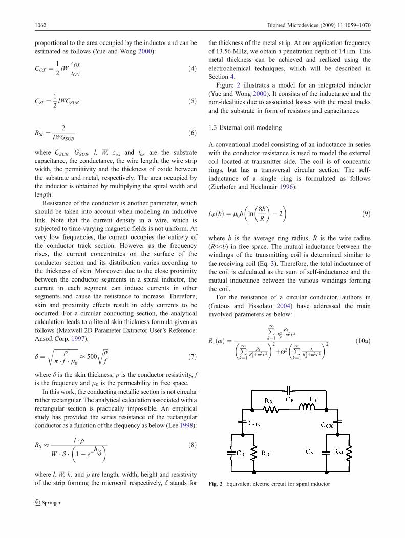
The characteristics of micro-strip structures on siliconsubstrate have been extensively investigated (Yue andWong 2000; Harrison 2007). For an accurate modeling ofthe integrated spiral inductances, the parasitic associatedwith the substrate should be taken into consideration. Ingeneral, a MOS micro-strip structure can be modeled by athree-element network comprised of COX, RSI, and CSI. Thephysical origin of RSI is the silicon conductivity which ispredominately determined by the majority carrier concen-tration. CSI models the high-frequency capacitive effectsoccurring in the semiconductor. For on-silicon spiral coils,the lateral dimensions are typically a few hundred micro-meters, which are much larger than the oxide thickness andare comparable to the silicon thickness. As a result, thesubstrate capacitance and resistance are approximately
Biomed Microdevices (2009) 11:1059–1070 1061
proportional to the area occupied by the inductor and can beestimated as follows (Yue and Wong 2000):
COX ¼ 1
2lW
"OXtOX
ð4Þ
CSI ¼ 1
2lWCSUB ð5Þ
RSI ¼ 2
lWGSUBð6Þ
where CSUB, GSUB, l, W, εox and tox are the substratecapacitance, the conductance, the wire length, the wire stripwidth, the permittivity and the thickness of oxide betweenthe substrate and metal, respectively. The area occupied bythe inductor is obtained by multiplying the spiral width andlength.
Resistance of the conductor is another parameter, whichshould be taken into account when modeling an inductivelink. Note that the current density in a wire, which issubjected to time-varying magnetic fields is not uniform. Atvery low frequencies, the current occupies the entirety ofthe conductor track section. However as the frequencyrises, the current concentrates on the surface of theconductor section and its distribution varies according tothe thickness of skin. Moreover, due to the close proximitybetween the conductor segments in a spiral inductor, thecurrent in each segment can induce currents in othersegments and cause the resistance to increase. Therefore,skin and proximity effects result in eddy currents to beoccurred. For a circular conducting section, the analyticalcalculation leads to a literal skin thickness formula given asfollows (Maxwell 2D Parameter Extractor User’s Reference:Ansoft Corp. 1997):
d ¼ffiffiffiffiffiffiffiffiffiffiffiffiffiffiffiffiffi
rp � f � m0
r� 500
ffiffiffirf
rð7Þ
where δ is the skin thickness, ρ is the conductor resistivity, fis the frequency and μ0 is the permeability in free space.
In this work, the conducting metallic section is not circularrather rectangular. The analytical calculation associated with arectangular section is practically impossible. An empiricalstudy has provided the series resistance of the rectangularconductor as a function of the frequency as below (Lee 1998):
RS � l � rW � d � 1� e�
h=d� � ð8Þ
where l, W, h, and ρ are length, width, height and resistivityof the strip forming the microcoil respectively, δ stands for
the thickness of the metal strip. At our application frequencyof 13.56 MHz, we obtain a penetration depth of 14μm. Thismetal thickness can be achieved and realized using theelectrochemical techniques, which will be described inSection 4.
Figure 2 illustrates a model for an integrated inductor(Yue and Wong 2000). It consists of the inductance and thenon-idealities due to associated losses with the metal tracksand the substrate in form of resistors and capacitances.
1.3 External coil modeling
A conventional model consisting of an inductance in serieswith the conductor resistance is used to model the externalcoil located at transmitter side. The coil is of concentricrings, but has a transversal circular section. The self-inductance of a single ring is formulated as follows(Zierhofer and Hochmair 1996):
LPðbÞ ¼ m0b ln8b
R
� �� 2
� �ð9Þ
where b is the average ring radius, R is the wire radius(R<<b) in free space. The mutual inductance between thewindings of the transmitting coil is determined similar tothe receiving coil (Eq. 3). Therefore, the total inductance ofthe coil is calculated as the sum of self-inductance and themutual inductance between the various windings formingthe coil.
For the resistance of a circular conductor, authors in(Gatous and Pissolato 2004) have addressed the maininvolved parameters as below:
R1 wð Þ ¼P1k¼1
Rk
R2kþw2L2
P1k¼1
Rk
R2kþw2L2
� �2
þw2P1k¼1
LR2kþw2L2
� �2 ð10aÞ
Fig. 2 Equivalent electric circuit for spiral inductor
1062 Biomed Microdevices (2009) 11:1059–1070

Rk ¼ x2k4psR2
ð10bÞ
L ¼ m0mr
4pð10cÞ
xk ¼2k � 1ð Þp
2þ p
4ð10dÞ
where σ is the conductivity of the metal forming the coilwindings.
Hence, the conductor forming the coil is similar to acylinder divided into a large number of parallel L-Rnetwork circuits. The summation of all said componentswill determine the series resistance of the external coil.
The inductive link forms a semi-coupled transformer.Since the coils of the link are not position-wise fixed, theperformance of the link is sensitive to the alignment of thetransmitting and receiving coils. In this traditional geometricalapproach, a loss of efficiency is accepted in exchange of a lackof sensitivity of the link.
The coupling between the two coils depends on theirshape, their geometrical dimensions and finally theirrelative orientation (side and angular misalignment). Thecoupling between the two coils can be calculated as follows(Zierhofer and Hochmair 1996; Soma et al. 1987):
M a; b;Δ; dð Þ ¼ pm0
ffiffiffiffiffiab
p Z10
J1 x
ffiffiffia
b
r� �� J1 x
ffiffiffib
a
r !
� J0 xΔffiffiffiffiffiab
p� �
� exp �xdffiffiffiffiffiab
p� �
dx ð11Þ
where Δ and d are the side misalignment and the separationdistance of the two coils respectively, a and b are the radius
of primary and secondary coils. This elliptic integral issolved by numerical methods.
2 Model properties and verification
The proposed model enabled us to analyze the geometricalconfiguration and characteristics of different micro-coils.An estimation of the inductance value remains challengingparticularly in RF designs (Carbunaru and Durand 2001;Burghartz 1996). The situation gets worse when the impactof the subjacent structure is entirely considered. In fact, thevalue of inductance along with its resistance determineinductor quality factor in a given application frequency.Obtaining an optimal inductance requires trade-offs betweenmany parameters including the selection of inductor config-uration and the applied fabrication process. Standard CMOStechnologies do not support specific processes such as diggingof the substrate under the inductor and the use of a thick metallayer.
To achieve a precise model of the inductive link, weincluded the parasitics associated with the inductor and thesubstrate of the conventional model. The proposed modelshown in Fig. 3 includes the inductance and the non-idealities due to associated losses with the metal strips, theoxide layer and the substrate in form of resistors andcapacitances. In the receiver side, CP and CR representcapacitances of the receiver resonant tank and the rectifiercharge reservoir respectively. COX, CSI, RSI and RR areparasitics associated with the oxide layer, substrate andreceiver micro-coil. Finally, LR stands for the inductance ofreceiver micro-coil.
Using the results from the previous sections, we modifythe expressions of series resistance of inductor, as well asthe value of the capacitance that is needed to achieveresonance at the receiver. The substrate parasitics are then
Fig. 3 Electrical model used forthe calculation of the powertransfer efficiency
Biomed Microdevices (2009) 11:1059–1070 1063

regarded as an additional parallel load for the link. Theserial impedance of this load can be expressed as follows(Djemouai and Sawan 1999):
ZSub S ¼ w � L2ð Þ2
2 1jwCOX
þ RSI1þjRSIwCSI
� ð12Þ
The series resistance of the inductor becomes:
R22 ¼ R2 þ real ZSub Sð Þ ð13Þ
where R2 is the receiver parasitic resistance, not shown ifFig. 1 for simplification.
Considering the link operating at resonance frequency,the new expression of capacitance is:
C22 ¼ 1
w Zj j ð14Þ
Replacing R2 and C2 by R22 and C22, we can determinethe power transfer efficiency and the correspondinggeometrical dimensions.
Finite elements method (Maxwell 2D Parameter ExtractorUser’s Reference: Ansoft Corp. 1997) has been used toobtain approximate and avoid complex analytical expres-sions. Thus extracting the S-parameter and then theimpedance of the inductive link can be found. Althoughthe electromagnetic simulations-based tools are capable ofobtaining highly accurate results but they require longsimulation.
Momentum software available under ADS electromag-netic environment was used to verify results carried out ofthe model. Once the intended inductor structure and theprocess parameters are in place, we run the electromagneticsimulations to determine the S-parameters of the structureand to eventually obtain the integrated inductor impedance.
Figure 4 plots the ADS and Matlab simulation results ofthe impedance (magnitude and phase) of an integratedspiral circular micro-coil versus frequency. Here, the micro-coil has an external diameter (De) of 4 mm, an internaldiameter (Di) of 1.2 mm, a spacing (Sp) between thewindings of 40µm, and a coil strip width (CW) of 100µm. Itis observed that there is close match between the theoreticalresults obtained from the proposed model by Matlab andelectromagnetic simulations by Momentum. However, themodel simulations are significantly shorter. The calculationof mutual inductance of the link coils was also verifiedbased on the experimental data obtained from finiteelement-based approaches (Zierhofer and Hochmair 1996;Fernandez et al. 2002).
The optimization of a micro-coil-based inductive links,from power transfer efficiency point of view, is initiated byproviding precise characterization of the inductor and theassociated parasitic such as the substrate and oxide parasitic.
Figure 5 depicts simulated power efficiency of aninductive link with various coating epoxy thicknesses(Separation distance). The conventional model, which doesnot consider the oxide losses, overestimates the efficiencyof this link.
Fig. 4 Impedance of coilextracted using ADS andMatlab simulation tools: (a)Magnitude, (b) Phase
Fig. 5 Power efficiency versus separation distance
1064 Biomed Microdevices (2009) 11:1059–1070

3 Array of micro-coils
The proposed configuration of the inductive link receiverconsists of multiple micro-coils. We consider the case ofone primary coil feeding four secondary ones, which arepositioned at the same distance from the central axis of theprimary coil. Figure 6(a) illustrates a 3D view of thestructure, and Fig. 6(b) shows the equivalent circuits ofthe proposed 4-coils links.
3.1 Variation of received power
In order to determine the current level in both primary andsecondary circuits, we write the system equations for eachcircuit as follows (Fig. 6b):
V1 ¼ Z1I1 þ jwMI2 þ jwMI3 þ jwMI4 þ jwMI5 ð15aÞ
0 ¼ Z1I1 þ jwMI1; i ¼ 2; 3; 4 and 5 ð15bÞ
which allow to extract the I1 expression:
I1j j ¼ V1j jR1 þ wMð Þ2
Z2þ wMð Þ2
Z3þ wMð Þ2
Z4þ wMð Þ2
Z5
ð16Þ
where R1=Z1.The maximum coupling is obtained when the two coils
are coaxial. When misalignment occurs between theimplanted micro-coils and the transmitting coil, the couplingcoefficient decreases, then the received power might decreaseand thus affects the functionality (Eq. 11).
Figure 7(a) depicts the proposed structure of the link atthe receiver side, which consists of an array of four similarcoils connected in series in a diagonal composition. Thissymmetrical configuration offers more tolerance against thedisplacement of the transmitter and receiver coils comparedwith the structure using one receiver coil. When amisalignment occurs, the power received by the half ofthe receiving coil (L1 or L2) increases, while in the otherhalf decreases. Using this topology, the inductive link
Fig. 6 Inductive link with four receivers: (a) A 3D view, (b)Equivalent circuit of the inductive link
Fig. 7 Multi-coil structure: (a) Schematic of diagonal-connectedcoils, (b) Desensitizing characteristics against to side misalignment
Biomed Microdevices (2009) 11:1059–1070 1065

becomes less sensitive to the lateral (side) as well asangular misalignment effects. Figure 7(b) shows thesimulation results for the energy captured by the receivercoils in the case of a side misalignment. The simulationcurrent available in both coils is constant even with amisalignment up to 5 mm.
3.2 Fabrication process of the micro-coils
A special fabrication process as shown in Fig. 8 is used tofabricate the micro-coils. We proceeded with a 6 inchesdiameter <100> silicon wafer on which we deposited anisolation thin layer (1µm) of photoresist by using a spinner.The wafer was subjected to 110°C temperature for 60 sec toincrease the adhesion of the deposited photoresist. Then a10 nm chromium layer was deposited on the photoresistusing Canon electron-beam equipment (Fig. 8(a)). Thislayer serves as an interface between the photoresist and thefollowing 1µm gold layer, which was also deposited withthe same process using the same electron-beam equipment(Fig. 8(b)). Thereafter, a photolithography process wasperformed in order to pattern the SR1813 positive photo-resist, which was already deposited on gold using a spinnerat 2,200 RPM for 35 s (Fig. 8(c)). Then, a standard MIF319developer was used for 45 sec to remove the exposedpositive photoresist (Fig. 8(d)). The implant was carried outon 125°C temperature for next 90 sec to increase theendurance of the said layer against etching in the followingsteps.
The exposed gold layer was etched using the solution (5%I2, 10% KI+ and 85% H2O) (Fig. 8(e)), and the exposedchromium one was etched using the solution (9% (NH4)2 Ce(NO3)6)
+, 6% HCLO4+ and 85% H2O) as illustrated in
Fig. 8(f).
4 Simulation and experimental results
Parameters such as electrical and physical characteristics,growth speed, reproducibility, cost, compatibility withmicroelectronics and microelectromechanical systems tech-nologies, fabrication steps and thick photolithography arereported to be involved in selection. They are used toevaluate the geometrical constraints of the micro-coils.
Figure 9 shows the negative mask, which includesdifferent configurations of the micro-coils. It depicts eightinductors, located in the wafer center, with arbitrary geomet-rical dimensions. They are used to validate the model. Eachinductor composed of a single micro-coil. The centralrectangle is the contact region, which allows the realizationof the micro-coils in the photoresist moulds. The fourstructures on the top, the bottom and both sides of the figureare intended to validate the proposed model of multipleinductors receiving coil.
Standard pads with 100µm pitch available in the0.18 micron CMOS process are used. For each micro-coil,a pair of pads is considered; one inside the spiral andanother one outside it, such that the radius of the inner
Fig. 8 Cross section of fabrica-tion process of the micro-coils
1066 Biomed Microdevices (2009) 11:1059–1070

spiral is much larger than the pad dimensions. This allowsimplementing the micro-coils in a single metal layer.Besides, the micro-coils were laid out far enough fromeach other to facilitate slicing tasks.
Two prototype structures of micro-coil, as per citedprocess, are fabricated which include single and array offour inductors as shown in Fig. 10. A conductive epoxywas employed to link the micro-coil terminals to otherelectronic parts. Figure 10(a) depicts the die photomicro-graph of single receiver micro-coil structures. It includeseight individual micro-coils with different spacing, numberof turns and interior diameter. Figure 10(b) shows thephotomicrograph of a single micro-coil with a diameter of4 mm optimized for maximum power transfer efficiency.Figure 10(c) illustrates the die photomicrograph of thefabricated 4-microcoil receiving structure.
These prototypes are used to validate the sequence offabrication steps and to verify the model. The electrical
Fig. 10 Microphotographs of :(a) Various single micro-coilsstructures, (b) Zoomed in singlemicro-coil, (c) Four-inductorreceiving coil structure
Fig. 9 Negative mask used with the positive photoresists
Biomed Microdevices (2009) 11:1059–1070 1067

characterization of the micro-coils was carried out using anAgilent 4294A precision impedance analyzer.
The external coil inductor is modeled as an inductancein-series with a resistor representing its associated losses.These components along with a series capacitor form aresonance tank in transmitter side. The required resistor andcapacitance were calculated such that the resonance occursat the application frequency of 13.56 MHz. This frequencymeets the Industrial, Scientific and Medical (ISM) norm.Once these passive components were chosen, we conductmeasurements of the completed inductive link. They consistof measuring the power delivered to a given load whilevarying the distance between the two coils. In this way, thepower efficiency can be eventually calculated.
Characterization of the multi-coil link is done as anextension of a single micro-coil structure. This is due tosimilarity in the dimensions and thus the inductance andassociated parasitic in integrated micro-coils. The proto-types were characterized with special emphasis on theenergy transfer performance.
Table 1 summarizes the experimental results from thissingle micro-coil receiver. This Table includes the dimen-sions, theoretical (model-based) and experimental powertransfer efficiencies of the micro-coil. Both the experimental-and theoretical-based results are of fair agreement. Theresults prove that the samples with reduced thickness(1 micron and less) suffer from reduction in the efficiency(around 4%). Note that samples 2, 5 and 8 do not have theneeded copper layer to make the measurements.
Table 1 presents the simulated and measured results forpower transfer efficiency obtained from the inductive linksusing single micro-coil structure having a metal thicknessof 1µm. This Table also shows the simulated results for the
samples with the same dimensions but having a metalthickness of 20μm. Here, the micro-coils are well aligned.Note that sample five has a too low resistance compared tothe other samples and consequently there was an over-lapping between the coil windings. This was caused by theblack traces stuck on the mask, which prevented the UVrays from hardening the mussels of the photoresist.
Figure 11 shows the reduction in the value of seriesresistance as the thickness of the metal tracks increases. Thesignificant difference is explained by the fact that due tothe skin effect, the series resistance increases when thethickness of metal is reduced. The series resistance is largerthan 35Ω and less than 5Ω for metal thicknesses of 1 and20µm respectively. However, from practical standpoints,implementing thick metal layers is a hard task. Therefore, atrade-off between the metal thickness and process simplicityshould be made.
Figure 12 plots the measured and simulated powerefficiency versus the distance between the external coil
Table 1 Dimensions, simulated and measured power transfer efficiency of one-inductor-based structure
Saa Nb Width (μm) Spc (μm) Internalradius (mm)
Metal thickness=1µm Metal thickness=20µm
Simulatedefficiency (%)
Measuredefficiency (%)
Simulatedefficiency (%)
1 15 70 30 0.6 3.42 2.56 21.90
2 10 70 20 1.2 3.87 N/Ad 26.65
3 13 70 50 0.6 3.09 3.24 23.64
4 10 70 40 1.0 3.18 2.71 25.03
5 12 100 30 0.6 4.18 N/A 25.78
6 8 100 10 1.2 4.38 4.00 29.12
7 11 100 40 0.6 3.71 3.48 25.95
8 8 100 40 1 3.74 N/A 27.66
a Sa = Samplesb N = Number of turnsc Sp = Spacingd N/A = Not Applicable
Fig. 11 Tracks series resistance vs metal thickness
1068 Biomed Microdevices (2009) 11:1059–1070

and receiving four micro-coils. Considering the agreementbetween the results obtained from model simulation andmeasurement, one may expect to achieve better performancewith a metal thickness of 20µm.
Concerning the output power versus the separationdistance of micro-coils, the link delivers 50 mW with anoptimum efficiency of 18%. This is at a distance of 1 cmbetween the external coil and receiving micro-coils. Thisefficiency is remarkably higher than that of previouslyreported inductive links using integrated receiver coils(Sawan et al. 2005b).
Table 2 summarizes the experimental results for powertransfer efficiency obtained from the inductive links usingsingle micro-coil receiver structure having a metal thicknessof 1µm. This Table also shows the simulated results for thesamples with the same dimensions but having a metalthickness of 20μm. Here, the micro-coils are well aligned.Note that sample five has a too low resistance compared tothe other samples. Also, this Table summarizes the resultsusing multiple (diagonally connected) micro-coil receiverstopology. It consists of four similar micro-coils using 1µmmetal thickness. Here, the micro-coils were subjected toremarkable side misalignment. The Table also shows the
simulated results for the samples with the same dimensionsand side misalignments but having a metal thickness of20µm. The results correlate well with simulated resultsobtained from the proposed model. In addition, this Tableshows that significant power efficiency improvement isexpected when using thick metal tracks for implementingthe micro-coils and under visible side misalignment con-ditions. However, the need for a special process outweighstheir advantage.
A comparison between the results stated in Tables 1and 2 shows a slight improvement in the power efficiencywhen using multi-coil receivers compared to the single-coilreceiver-based structure. The side misalignment column inTable 2 represents the maximum distance of lateralmisalignment that does not affect the link functionality.Analyzing the side misalignment confirms that the newproposed structure could successfully help for stabilizationof the efficiency even with 1.5 cm of lateral misalignment.This is considered as a significant improvement in theperformance of the inductive link. An important remainingchallenge in the design of inductive links is compensationfor efficiency degradation due to lateral or angularmisalignments of the coils. It occurs when one coil moveswith respect to the other.
5 Conclusion
A new model for inductively-coupled links with anintegrated receiver micro-coil was presented. The link isused to transfer energy to implantable devices within shortdistances in an efficient manner. The model accounts for thelosses (oxide and silicon) associated with the receivermicro-coil and can precisely evaluate the performance ofinductive link in terms of power transfer efficiency. Themodel was characterized using Matlab and was verifiedemploying simulation tools under ADS electromagneticenvironment. Using the model, the geometry constraints
Fig. 12 Simulation and experimental power efficiency versusseparation distance
Table 2 Dimensions, side misalignment, simulated and experimental energetic efficiency of 4-inductor-based structure
Saa Nb Width (μm) Spc (μm) Internalradius (mm)
Side mis-alignment(cm)
Metal thickness=1µm Metal thickness=20µmExperimental powerefficiency (%)
Simulated powerefficiency (%)
1 23 50 10 0.6 1 5.18 28.40
2 20 50 10 0.8 1.5 4.44 29.32
3 20 80 10 0.2 N/Ad N/A 24.70
4 13 80 10 0.8 N/A N/A 21.90
a Sa = Samplesb N = Number of turnsc Sp = Spacingd N/A = Not Applicable
Biomed Microdevices (2009) 11:1059–1070 1069

were examined and the optimal dimensions of the coilsforming the link were determined. Finally, a new structurefor micro-coils was proposed which desensitizes the linkagainst both the side and the angular misalignments. It alsoenabled us to forecast that the fabrication of thick-metalmicro-coils (>10 mm) leads to a remarkable improvementin terms of power transfer efficiency. As an extension tothis work, we suggest the use of metal thickness of 10μm.
Prototypes of integrated micro-coils were fabricated tovalidate the performance improvements obtained throughoutthe model simulation. The results significantly satisfied thetheoretical expectations. A new structure for micro-coils wasintroduced that desensitized the link to both side and angularmisalignments. A custom fabrication process using 1 micronmetal thickness was also presented by which two sets ofmicro-coil varying in number of coils were fabricated. Theprototypes were used to realize inductive links. The first setpossesses one coil 4 mm of diameter and represents a powerefficiency close to 4% while the second set possesses multi-coils with an efficiency of 18%. The resulting optimized linkcan deliver 50 mW of power to an implantable intracorticalstimulator. The experimental results were remarkably inagreement with those obtained from simulations.
Acknowledgment The authors would like to acknowledge thefinancial support from NSERC and the Canadian Research Chair inSmart Medical Devices, and the design and fabrication tools providedby CMC Microsystems.
References
American National Standards Institute (1974) Safety level ofelectromagnetic radiation with respect to personnel,” ANSIC95.1-1974, IEEE, NY
S. Babic, C. Akyel, Improvement in calculation of the self- and mutualinductance of thin-wall solenoids and dick coils. IEEE Trans Magn36(4), 1970–1975 (2000) doi:10.1109/TMAG.2000.875240
J.N. Burghartz, Microwave inductors and capacitors in standardmultilevel interconnect silicon technology. IEEE Trans MicrowTheory Tech 44(1), 100–104 (1996). doi:10.1109/22.481391
R. Carbunaru, D.M. Durand, Toroidal coil models for transcutaneousmagnetic simulation of nerves. IEEE Trans Biomed Eng 48, 434–441 (2001). doi:10.1109/10.915709
J. Coulombe, M. Sawan, J.-F. Gervais, A highly Flexible System forMicrostimulation of the visual cortex: design and implementa-tion. IEEE Trans Biomed Circuits Syst 1(4), 270–277 (2007).doi:10.1109/TBCAS.2007.916026
A. Djemouai, M. Sawan (1999). Prosthetic power supplies, encyclopediaof electrical and electronics engineering, J. G. Webster, Wiley,Vol.17, pp. 413–421
N.N. Donaldson, T.A. Perkins (1983). Analysis of resonant coupledcoils in the design of radio frequency transcutaneous links. MedBiol Eng Comput:612–627 (1983) doi:10.1007/BF02442388
C. Fernandez, O. Garcia, R. Prieto, J.A. Cobos, S. Gabriels, G. Van DerBorght (2002). Design issues of a core-less transformer for acontact-less application. IEEE Applied Power Electronics Conf.(APEC), Dallas
M. Ferrari, V. Ferrari, D. Marioli, A. Taroni, Modeling, fabrication andperformance measurements of a pirezoelectric energy converter forpower harvesting in autonomous microsystems. IEEE Trans InstrumMeas 55(6), 2096–2101 (2006). doi:10.1109/TIM.2006.884114
K. Finkenzeller (2003) RFID-Handbook. Wiley, 2nd edn. ISBN:0,470,844,027, Hoboken, NJ, 2003
O.M.O. Gatous, J. Pissolato (2004). Frequency-dependent skin-effectformulation for resistance and internal inductance of a solidcylindrical conductor. IEEE Proc. Microwaves. Antennas Propag.151(3), 212–216 (2004)
M. Gross et al. (1999) Optical signal and energy transmission for aretina implant. Proc. First Joint Meeting of BMES and EMBS,pp. 476, Atlanta, USA
G. Gunnar, E. Bruun (2002). CMOS circuit design for RF sensors.Kluwer Academic Publishers
R.R. Harrison (2007). Designing efficient inductive power links forimplantable devices. IEEE, Int’l Symp. Circuits and Systems, pp.2080–2083
T. Ishiyama, Y. Kanai, J. Ohwaki, M. Mino (2003). Wireless powertransmission system using ultrasonic air transducer for mobileApplications (in Japanese). Mech Eng Cong, Japan, pp. 273–274
B. Jiang, J.R. Smith, M. Philipose, S. Rou, K. Sundara-Rajan, A.V.Mamishev, Energy scavenging for inuctively passive RFIDsystems. IEEE Trans Instrum Meas 56(1), 118–125 (2007).doi:10.1109/TIM.2006.887407
R.W.P. King, The electric field induced in the human body when exposedto electromagnetic fields at 1–30 M Hz on shipboard. IEEE TransBiomed Eng 46, 747–751 (1999). doi:10.1109/10.764951
Y.K. Koutsoyannopoulos, Y. Papananos, Systematic analysis andmodeling of integrated inductors sna transformers in RFIC design.IEEE Trans Circuits Syst II 47(8), 699–713 (2000). doi:10.1109/82.861403
T.H. Lee (1998) The design of CMOS radio-frequency integratedcircuits. Cambridge University Press, 1998
S.F. Mahmoud, E. Beyne, Inductance and quality-factor evaluation ofplanar lumped inductors in a multilayer configuration. IEEE TransMicrow Theory Tech 45(6), 918–923 (1997). doi:10.1109/22.588602
Maxwell 2D parameter extractor user’s reference: Ansoft Corp., 1997C. Sauer, M. Stanacevic, G. Cauwenberghs, N. Thakor, Power harvesting
and telemetry in CMOS for implanted devices. IEEE Trans CircuitsSyst I 52(12), 1605–2613 (2005). doi:10.1109/TCSI.2005.858183
M. Sawan, Y. Hu, J. Coulombe, Wireless smart implants dedicated tomultichannel monitoring and microstimulation. IEEE Circuits SystMag 5(1), 21–39 (2005a) doi:10.1109/MCAS.2005.1405898
M. Sawan, Y. Hu, J. Coulombe (2005) Wirelessly powered andbidirectional data exchange in smart medical microsystems. Proc.IEEE Custom Integrated Circuits Conf., pp. 5–12
M. Sehil, A. Khouas, M. Sawan (2005) Modeling efficient inductivepower transfer required to supply implantable devices. The Int.Functionnal Electrical Stimulation Society Conference, Montréal
M. Soma, D.C. Galbraith, R.L. White, Radio-frequency coils inimplantable devices: misalignment analysis and design proce-dure. IEEE Trans Biomed Eng BME 34(4), 276–282 (1987).doi:10.1109/TBME.1987.326088
Z. Tang (1997) A multi-channel implantable stimulation and telemetrysystem for neuromuscular control. Dissertation, Case WesternReserve University
C.P. Yue, S.S. Wong, Physical modeling of spiral inductors on silicon.IEEE Trans Electron Dev 47(3), 560–568 (2000). doi:10.1109/16.824729
C.M. Zierhofer, E.S. Cochmair (1996). Coil design for improvedpower transfer efficiency in inductive links. Proc. IEEE Int.Engineering in Medicine and Biology Society, pp. 1538–1539
C.M. Zierhofer, E.S. Hochmair, Geometric approach for couplingenhancement of magnetically coupled coils. IEEE Trans BiomedEng 43(7), 708–714 (1996). doi:10.1109/10.503178
1070 Biomed Microdevices (2009) 11:1059–1070
Copyright © 2022 FDOKUMEN