Large displacement elastoplastic analysis of frames using an iterative LCP approach
Upload
khangminh22Category
view
0download
0
Citation: Yun, S.; Koh, C.S.; Seo, J.;
Shim, S.; Park, M.; Jung, H.H.; Eom,
K.; Chang, J.W.; Kim, S.J. A Fully
Implantable Miniaturized Liquid
Crystal Polymer (LCP)-Based Spinal
Cord Stimulator for Pain Control.
Sensors 2022, 22, 501. https://
doi.org/10.3390/s22020501
Academic Editor: Jungsuk Kim
Received: 14 December 2021
Accepted: 6 January 2022
Published: 10 January 2022
Publisher’s Note: MDPI stays neutral
with regard to jurisdictional claims in
published maps and institutional affil-
iations.
Copyright: © 2022 by the authors.
Licensee MDPI, Basel, Switzerland.
This article is an open access article
distributed under the terms and
conditions of the Creative Commons
Attribution (CC BY) license (https://
creativecommons.org/licenses/by/
4.0/).
sensors
Article
A Fully Implantable Miniaturized Liquid Crystal Polymer(LCP)-Based Spinal Cord Stimulator for Pain ControlSeunghyeon Yun 1,†, Chin Su Koh 2,† , Jungmin Seo 1, Shinyong Shim 1, Minkyung Park 2, Hyun Ho Jung 2 ,Kyungsik Eom 3,* , Jin Woo Chang 2,* and Sung June Kim 1
1 Department of Electrical and Computer Engineering, College of Engineering, Seoul National University,Seoul 08826, Korea; [email protected] (S.Y.); [email protected] (J.S.); [email protected] (S.S.);[email protected] (S.J.K.)
2 Department of Neurosurgery, College of Medicine, Yonsei University, Seoul 03722, Korea;[email protected] (C.S.K.); [email protected] (M.P.); [email protected] (H.H.J.)
3 Department of Electronics Engineering, College of Engineering, Pusan National University,Busan 46241, Korea
* Correspondence: [email protected] (K.E.); [email protected] (J.W.C.)† These authors contributed equally to this work.
Abstract: Spinal cord stimulation is a therapy to treat the severe neuropathic pain by suppressingthe pain signal via electrical stimulation of the spinal cord. The conventional metal packaged andbattery-operated implantable pulse generator (IPG) produces electrical pulses to stimulate the spinalcord. Despite its stable operation after implantation, the implantation site is limited due to its bulkysize and heavy weight. Wireless communications including wireless power charging is also restricted,which is mainly attributed to the electromagnetic shielding of the metal package. To overcome theselimitations, here, we developed a fully implantable miniaturized spinal cord stimulator based on abiocompatible liquid crystal polymer (LCP). The fabrication of electrode arrays in the LCP substrateand monolithically encapsulating the circuitries using LCP packaging reduces the weight (0.4 g) andthe size (the width, length, and thickness are 25.3, 9.3, and 1.9 mm, respectively). An inductive linkwas utilized to wirelessly transfer the power and the data to implanted circuitries to generate thestimulus pulse. Prior to implantation of the device, operation of the pulse generator was evaluated,and characteristics of stimulation electrode such as an electrochemical impedance spectroscopy (EIS)were measured. The LCP-based spinal cord stimulator was implanted into the spared nerve injury ratmodel. The degree of pain suppression upon spinal cord stimulation was assessed via the Von Freytest where the mechanical stimulation threshold was evaluated by monitoring the paw withdrawalresponses. With no spinal cord stimulation, the mechanical stimulation threshold was observed as1.47 ± 0.623 g, whereas the stimulation threshold was increased to 12.7 ± 4.00 g after spinal cordstimulation, confirming the efficacy of pain suppression via electrical stimulation of the spinal cord.This LCP-based spinal cord stimulator opens new avenues for the development of a miniaturized butstill effective spinal cord stimulator.
Keywords: spinal cord stimulation; liquid crystal polymer; implantable device; pain control
1. Introduction
Spinal cord stimulation is a therapeutic tool used to treat certain chronic pain condi-tions especially related to neuropathic pain caused by trauma or postoperative sequelaeand sensory nerve damage [1–3]. The idea was to deliver electric current pulses to thespinal cord through an electrode inserted into the fat layer of the spine [4]. Based on thewell-known gate control theory, the stimulation current delivered to the spinal cord inhibitsthe transmission of the nociceptive information as well as other sensory information [5–8].Since the effects of pain suppression persist only while the stimulation is being delivered,
Sensors 2022, 22, 501. https://doi.org/10.3390/s22020501 https://www.mdpi.com/journal/sensors

Sensors 2022, 22, 501 2 of 12
an implantable spinal cord stimulator that allows continuous activation of the spinal cordto alleviate the pain is crucial for the patients suffering chronic neuropathic pain.
The efficacy of spinal cord stimulation has been demonstrated in several clinicalstudies, and commercial spinal cord stimulators have been developed for human use [9–12].Medtronic developed a spinal cord stimulator that includes stimulation electrodes anda universal implantable pulse generator (IPG; PrimeAdvanced, Medtronic, Minneapolis,MN, USA). The titanium packaged IPG operated by a battery produces stimulation pulsesvia a constant voltage scheme whose stimulation amplitude and frequency lies in the rangefrom 2 to 130 Hz and from 0 to 10.5 V, respectively [13]. Stimulation pulses are deliveredthrough the polyurethane-insulated Pt-Ir electrodes of a wire diameter of 1.3 mm [14].Nevro Corporation have developed a spinal cord stimulation system, Senza System, whichconsist of two eight-channel percutaneous electrodes, an IPG, and an anchor. Upon currentstimulation, neurons in the target area are desensitized resulting in the local paresthesia, atingling sensation, and finally masking the pain without interlocking with other senses [9].Although the stimulation rate used in this system lies in the kilohertz region, far from thewidely employed stimulation rate of 40 to 60 Hz [15–17], the pain reduction efficacy hasbeen proven in clinical trials. Al-Kaisy et al. reported that 88% (72 out of 82) of patientsshowed a significant improvement in pain score [18], and Kapural et al. demonstrated thatkilohertz spinal cord stimulation effectively reduced the pain even without paresthesia [10].
Despite their successes in alleviating the chronic pain, these devices have severallimitations, which originated from the following features. Since IPGs are packaged bythe metal, its volume and the weight are fairly bulky and heavy (i.e., the volume and theweight of the PrimeAdvanced are around 40 cm3 and 70 g, respectively), leading to variouscomplications after implantation as well as restriction in the implantation location (i.e.,hip or abdomen) [4,13,19]. Since the location of the implanted IPG is distant away fromthe actual stimulation position, a long lead wire is required to connect the electrode andthe IPG [13,17], which results in complicated surgery for making a tunnel under the skinand risk of infection of a widespread lead wire. The use of metal as a packaging materialraised a problem of electromagnetic shielding impeding the electromagnetic (EM) wavesfor wireless power and data transmission [20,21]. Moreover, an excessive heat is generatedat the metal package when it exposed to the strong alternating magnetic field especiallyduring the magnetic resonance (MR) imaging [22–24]. Since a lead wire is encapsulatedby a silicone whose moisture absorption rate (>1%) is significantly higher than that of themetal, the moisture can infiltrate through the gap between the electrode and the circuit,and in the worst case, the circuit as well as the human may be at risk.
LCP has been widely employed as an insulating and substrate material for not onlyin the implantable devices but also in the microwave integrated circuit due to its biocom-patibility and low moisture absorption rate (<0.04%) compared to other polymers such aspolyimide, parylene, or silicon elastomer [25–28]. Moreover, due to its flexible but strongmechanical properties, the LCP-based neural probe does not require a guiding post topierce the dura, a rigid sheath covering the brain, during brain insertion [29,30]. Previousstudies have demonstrated the fabrication process of LCP-based neural probes via semi-conductor processes where the LCP is employed as both the substrate and encapsulationmaterial [29,31]. With the exception of small electrodes and metal wires, LCP-based neu-ral probes are composed of the LCP polymer allowing EM waves to penetrate withoutseriously damping its signal for wireless power and data delivery [32,33].
In this study, we developed a fully implantable neural stimulator using LCP for spinalcord stimulation. Unlike conventional spinal cord stimulators employing metal-basedpackaging and manually assembled electrode array, the developed spinal cord stimulatoruses the lightweight and semi-hermetic LCP to develop micro-fabricable and ultrathinelectrode arrays and to monolithically encapsulate the device. An inductive link wasutilized to transmit power and data to the implanted circuitry. A pulse generation circuitand microfabricated electrode arrays are monolithically integrated and packaged. The

Sensors 2022, 22, 501 3 of 12
fabricated stimulator was evaluated in vivo to demonstrate the pain suppression effect ofthe spinal cord stimulator.
2. Materials and Methods2.1. System Overview
The spinal cord stimulator system consists of an implanted neural stimulator andtwo external devices: a skin attached external relay and a remote controller (Figure 1). Stim-ulation protocols are preset at the controller and delivered to the external relay via Zigbeecommunication [34]. Then, the external relay transfers received stimulation protocols andpower to the implanted neural stimulator via an inductive link. The neural stimulatorconsisting of an electrode array, a receiver coil, and an application-specific integrated circuit(ASIC) circuitries generating biphasic current pulses were implemented and monolithicallypackaged using a flexible LCP layer. The neural stimulator located outside of the vertebragenerates electrical stimulation pulses and send them to the microfabricated electrodesimplanted at the epidural part of the spinal cord to stimulate target neurons (Figure 1).
Sensors 2022, 22, x FOR PEER REVIEW 3 of 12
and microfabricated electrode arrays are monolithically integrated and packaged. The fabricated stimulator was evaluated in vivo to demonstrate the pain suppression effect of the spinal cord stimulator.
2. Materials and Methods 2.1. System Overview
The spinal cord stimulator system consists of an implanted neural stimulator and two external devices: a skin attached external relay and a remote controller (Figure 1). Stimu-lation protocols are preset at the controller and delivered to the external relay via Zigbee communication [34]. Then, the external relay transfers received stimulation protocols and power to the implanted neural stimulator via an inductive link. The neural stimulator consisting of an electrode array, a receiver coil, and an application-specific integrated cir-cuit (ASIC) circuitries generating biphasic current pulses were implemented and monolith-ically packaged using a flexible LCP layer. The neural stimulator located outside of the ver-tebra generates electrical stimulation pulses and send them to the microfabricated electrodes implanted at the epidural part of the spinal cord to stimulate target neurons (Figure 1).
Figure 1. A fully implantable neural stimulation system. The neural stimulator consisting of an im-plantable pulse generator and stimulation electrodes are located outside of the vertebra and at the epidural part of the spinal cord, respectively. The external relay is attached on the skin to wirelessly transfer the power and data to the implanted neural stimulator.
2.2. Neural Stimulator 2.2.1. Electrode Array
Electrode arrays were microfabricated on LCP films [30,35]. Briefly, the LCP film was first attached onto the 4-inch silicon wafer using an elastomer. The elastomer (MED 6233, Nusil Silicone Technology, Carpinteria, CA, USA) acting as a glue was spin-coated on the wafer. A 25 μm-thick LCP film with high melting temperature (HT-LCP; 330 °C, Vecstar CT-Z series, Kuraray, Japan) was laser cut into 4-inch-wafer-sized pieces using a UV laser system (Samurai System, DPSS, Los Angeles, CA, USA). The cut LCP piece was attached to the elastomer coated silicon wafer using a roller. As for the first procedure of metal patterning, the LCP substrate was placed under O2 plasma for 180 s using an etcher (Ox-ford Etcher 80Plus, Oxford Instruments, Abingdon, UK). Subsequently, a 50 nm-thick ti-tanium layer and a 100 nm-thick gold layer were sequentially deposited on the LCP sub-strate by evaporation. A photoresist layer (AZ4620, Clariant, Muttenz, Switzerland) was spin-coated on the gold layer and patterned using an aligner (MA6/BA6, SUSS MicroTec,
Figure 1. A fully implantable neural stimulation system. The neural stimulator consisting of animplantable pulse generator and stimulation electrodes are located outside of the vertebra and at theepidural part of the spinal cord, respectively. The external relay is attached on the skin to wirelesslytransfer the power and data to the implanted neural stimulator.
2.2. Neural Stimulator2.2.1. Electrode Array
Electrode arrays were microfabricated on LCP films [30,35]. Briefly, the LCP film wasfirst attached onto the 4-inch silicon wafer using an elastomer. The elastomer (MED 6233,Nusil Silicone Technology, Carpinteria, CA, USA) acting as a glue was spin-coated on thewafer. A 25 µm-thick LCP film with high melting temperature (HT-LCP; 330 C, VecstarCT-Z series, Kuraray, Japan) was laser cut into 4-inch-wafer-sized pieces using a UV lasersystem (Samurai System, DPSS, Los Angeles, CA, USA). The cut LCP piece was attachedto the elastomer coated silicon wafer using a roller. As for the first procedure of metalpatterning, the LCP substrate was placed under O2 plasma for 180 s using an etcher (OxfordEtcher 80Plus, Oxford Instruments, Abingdon, UK). Subsequently, a 50 nm-thick titaniumlayer and a 100 nm-thick gold layer were sequentially deposited on the LCP substrate byevaporation. A photoresist layer (AZ4620, Clariant, Muttenz, Switzerland) was spin-coatedon the gold layer and patterned using an aligner (MA6/BA6, SUSS MicroTec, Garching,Germany) and a developer (AZ300, AZ Electronic Materials, Luxembourg). An 8 µm-thickgold layer was electroplated on the areas without photoresist followed by removing the

Sensors 2022, 22, 501 4 of 12
photoresist by applying it using a striper (AZ700, AZ Electronic Materials, Luxembourg).The remaining thin metal layers on the LCP were etched with aqua regia and HF. Finally,the outlining process was performed by lasers machining using the UV laser system forpost-lamination processes.
2.2.2. ASIC Circuitries and Receiver Coil
The ASIC circuitries for the implanted neural stimulator is capable of wireless powerand data transmission, voltage level adjustment, and neural stimulation. The data contain-ing desired stimulation parameters are fed into the internal device via an inductive linkoperated at 2.5 MHz. To convert the pulse-width modulated (PWM) data to half-sinusoidalsignals, the wirelessly received data are fed into a resistor and a 3.3 V Zener diode. Basedon half-sinusoidal signals, an ASIC generates biphasic electrical stimulation pulses whosestimulation frequency, duration, and current magnitude are in the range of 20 to 230 Hz,10 to 630 µs, and 0.01 to 10.23 mA, respectively. Along with the data transmission, 3.3 Vconstant voltage is produced to power an oscillator (LTC6906, Linear Technology, Milpitas,CA, USA) and the digital circuitry of the ASIC. Pulse-width modulated signals are firstrectified at the rectifier which are then fed into the Zener diode connected with a capacitorto clamp the voltage to 15 V. Finally, 15 V is used to create 3.3 V constant voltage, which isproduced at the regulator (NCP71533, On Semiconductor, Phoenix, AZ, USA). The ASICcircuitries were fabricated on the 100 µm-thick copper-cladded LCP films (HT-LCP, UL-TRALAM 3850, Rogers Corporation, Chandler, AZ, USA) whose melting temperature wasthe same as that of the LCP film used in the electrode array layer. A stimulation generatorASIC was wire-bonded, and the other auxiliary electronics including a regulator, Zenerdiode, oscillator, and rectifier were mounted using conductive epoxy and baked in the ovenat 100 C for 1 h to harden the epoxy.
We designed a spirally wound and rectangular-shaped receiver coil whose outer width,outer length, inner width, inner length, line width, number of turns, and number of layersare 18 mm, 6 mm, 13 mm, 1 mm, 100 µm, 26 turns, and 2 layers, respectively. Analogousto the ASIC circuitries, the receiver coil is fabricated on the 100 µm-thick copper-claddedHT-LCP films (ULTRALAM 3850, Rogers Corporation, USA). The tuning capacitor wasconnected in parallel with respect to the receiver coil to form a parallel resonance circuit tomaximize the power transmission efficiency.
2.2.3. Monolithic Integration and Packaging
The layers of ASIC circuitries, electrode arrays, and coil were sequentially stacked. Asadhesive layers, 25 µm-thick LCP films with a low melting temperature (LT-LCP; 280 C,Vecstar CT-F series, Kuraray, Tokyo, Japan) were placed in between each adjacent layer(Figure 2). All the films were aligned in a pair of custom-designed aluminum jig andlaminated at 285 C for 10 min with a load of 2 kg/cm2 in a heat press (Model 4330, Carver,Wabash, IN, USA). Two via holes were made at the markers on the ASIC circuitries andelectrode array layers by the laser machining. The via holes were filled with conductiveepoxy (H20E, Epotek, Billerica, MA, USA) to connect coil to the ASIC circuitries. Prior tothe packaging process, a series of laser-machining (Samurai System, DPSS, USA) processesincluding electrode site opening and an outlining process were performed.
Two lids were fabricated to encapsulate the system. Briefly, 100 µm thick LT- andHT-LCP films were laser cut to have dimensions of 20 mm × 40 mm. Two HT-LCP films andtwo LT-LCP films were stacked one after another to form a pair of LCP layers. Two pairsof LCP layers were aligned using custom-designed aluminum jigs of which to make topand bottom package lids. One pair of jigs was designed to have curvature to shape the toppackage lid. These LCP layers were thermally laminated together and deformed using aheat press (290 C for 10 min with a load of 2 kg/cm2) to form 400 µm thick top and bottompackage lids in desired shapes, as shown in Figure 2b.

Sensors 2022, 22, 501 5 of 12
Sensors 2022, 22, x FOR PEER REVIEW 5 of 12
a heat press (290 °C for 10 min with a load of 2 kg/cm2) to form 400 μm thick top and bottom package lids in desired shapes, as shown in Figure 2b.
Figure 2. (a) A block diagram of the neural stimulator and the external relay. The internal device receives power and data from the external relay through 2.5 MHz inductive link to generate a bi-phasic pulse. (b) Fabrication process of the designed neural stimulator. Microfabricated elec-trode/circuit layers are thermally laminated, laser machined, and electrical components are mounted before being packaged with customized LCP (liquid crystal polymer) lids. HT-LCP: high melting temperature LCP, LT-LCP: low melting temperature LCP.
The assembled stimulator circuit board was placed in between the two package lids with the electrode extruded at the center of a rounded lid corner. The circuit board was fixed at the bottom lid by locally applied heat at the rim of the board. This was followed by thermal lamination on the edge of the package with a 2 mm margin for biocompatible encapsulation of the electronics to protect them from body fluids. The edge of the package was trimmed by a laser.
2.3. External Devices The stimulation parameters (the channel configuration, the pulse amplitude, the
pulse width, and the pulse rate) and ON/OFF commands are adjusted at the remote con-troller and wirelessly delivered to the external relay via two Zigbee-compliant RF trans-ceivers (CC2530, Texas Instrument, Dallas, TX, USA) implemented on either side of exter-nal devices [34]. Once receiving the data from the remote controller, the wireless trans-ceiver at the external relay tailors the stimulation parameters and controls the class-E am-plifiers by generating pulse-width modulated (PWM) data from the general-purpose in-put/output (GPIO). The class-E amplifier along with the transmitter coil was driven by a PWM-modulated 2.5 MHz sinusoidal wave to deliver the power and data to the internal
Figure 2. (a) A block diagram of the neural stimulator and the external relay. The internal devicereceives power and data from the external relay through 2.5 MHz inductive link to generate a biphasicpulse. (b) Fabrication process of the designed neural stimulator. Microfabricated electrode/circuitlayers are thermally laminated, laser machined, and electrical components are mounted before beingpackaged with customized LCP (liquid crystal polymer) lids. HT-LCP: high melting temperatureLCP, LT-LCP: low melting temperature LCP.
The assembled stimulator circuit board was placed in between the two package lidswith the electrode extruded at the center of a rounded lid corner. The circuit board wasfixed at the bottom lid by locally applied heat at the rim of the board. This was followedby thermal lamination on the edge of the package with a 2 mm margin for biocompatibleencapsulation of the electronics to protect them from body fluids. The edge of the packagewas trimmed by a laser.
2.3. External Devices
The stimulation parameters (the channel configuration, the pulse amplitude, thepulse width, and the pulse rate) and ON/OFF commands are adjusted at the remotecontroller and wirelessly delivered to the external relay via two Zigbee-compliant RFtransceivers (CC2530, Texas Instrument, Dallas, TX, USA) implemented on either side ofexternal devices [34]. Once receiving the data from the remote controller, the wirelesstransceiver at the external relay tailors the stimulation parameters and controls the class-Eamplifiers by generating pulse-width modulated (PWM) data from the general-purposeinput/output (GPIO). The class-E amplifier along with the transmitter coil was driven by aPWM-modulated 2.5 MHz sinusoidal wave to deliver the power and data to the internalstimulation ASIC via inductive link. A 1300 mAh lithium battery (TW-103440, The Han,Korea) is used to supply the power to the external relay.

Sensors 2022, 22, 501 6 of 12
2.4. System Evaluation
The performance of the spinal cord stimulator system was evaluated in bench. First,the overall operation of the system was monitored to confirm whether desired stimulationpulses were generated. After setting the stimulation parameter at the remote controller,the output voltage of the regulator was monitored to validate the power delivery, andthe ASIC chip generated stimulation waveform was monitored to evaluate the overallsystem operation. During the evaluation, the distance between the remote controller tothe external relay was kept within the reliable transmission range, and the external relaywas separated by 5 mm apart from the neural stimulator. Next, the performance of thestimulation electrode was evaluated to confirm whether the generated stimulation pulsecan be delivered to the neural tissue. The electrochemical impedance spectroscopy (EIS)and cyclic voltammetry (CV) of the fabricated electrode arrays were measured with apotentiostat (SI 1287/SI 1260, Solatron, Hampshire, UK) configured as a three-electrodecell using an Ag/AgCl reference electrode and a Pt counter electrode in PBS solution (1X,Gibco). The EIS was measured with a frequency ranging from 1 Hz to 100 kHz by applying10 mV of sinusoidal wave. The CV curve was obtained by monitoring the current flowingthrough the electrode array while sweeping the voltage in the range of −0.8 to 0.6 V.
2.5. Animals and In Vivo Evaluation Setup
A total of 5 adult male Sprague–Dawley rats (Orientbio Inc., Osan, Korea) weighingin the range from 200 to 250 g were used in this study. Rats were individually housedin polycarbonate cages with wood chip bedding while free access to food and water wasallowed. A 12 h light/dark cycle (light: 08:00–20:00) was maintained with a housingtemperature and humidity of 24 ± 2 and 55 ± 5%, respectively. The Institutional AnimalCare and Use Committee of Yonsei University (IACUC no. 2016-0161, date of approval26 September 2016) approved the study. A spared nerve injury (SNI) model was chosenas a neuropathic pain model [36]. Rats were anesthetized via an intraperitoneal injectionof pentobarbital (40 mg/kg) (Hanlim Pharm, Yongin, Korea). The rats were injected with0.1 mL of atropine (Huons, Seongnam, Korea) 10 min before the pentobarbital injectionto ensure the stability of anesthesia. The left sciatic nerve was exposed, and three majordivisions of the sciatic nerve (tibial, sural, and common peroneal nerve) were clearlyseparated. To generate an efficient neuropathic pain model, the common peroneal and tibialnerves were completely ligated and transected, leaving the sural nerve intact. Hemostasiswas completed, and the cut was closed with muscle and skin sutures. One week aftersurgery, we measured the pain threshold to confirm whether neuropathic pain has beeninduced. After a behavioral test, rats that did not show neuropathic pain response wereexcluded from this study. To implant the spinal cord neural stimulator (SCNS), ratswere anesthetized with pentobarbital sodium and a midline skin incision was made, andlaminectomy was performed to access the spinal cord. The SCNS electrode was implantedepidurally between thoracic 13 (T13) and lumbar 1 (L1) level. Caution was taken to avoidpenetrating the dura while inserting the electrode. The package part connected to theelectrode was placed in line with the vertebra and fixed with sutures. The wounds wereclosed with sutures, and the stimulation test commenced three days thereafter.
Rats were placed inside acrylic cages (8 cm × 10 cm × 20 cm) on a wire mesh grid, andthe external relay was attached to the back of the rats. Innocuous mechanical stimulationwas applied with a von Frey filament to the lateral edge of the left hind paw to measurethe thresholds of the flexion withdrawal reflex in response to mechanical stimulation ofthe hind limb. As a control experiment, the threshold was measured while no electricalstimulation was applied. To modulate the pain signal by electrical stimulation, the biphasiccurrent stimulation pulses were delivered to the spinal cord having the pulse rate andthe duration of 38.8 Hz and 120 µs, respectively. To confirm the efficacy of electricalspinal cord stimulation for pain-relieving effects, the mechanical withdrawal thresholdwas measured followed by four different stimulation parameters (pre-stimulation, 100, 250,and 500 µA). Electrical stimulation was maintained for 15 min for each parameter, and a

Sensors 2022, 22, 501 7 of 12
von Frey test was performed afterwards. To remove the effect of the previous test, the nextelectrical stimulation was delivered at an interval of one hour. Rats were sacrificed after allexperiments, and the spinal cord stimulation device was removed from the rats.
2.6. Statistical Analysis
All data are presented as the mean ± standard error of the mean (SEM). GraphPadPrism 5 (GraphPad Software, Inc., La Jolla, CA, USA) was used to create graphs andperform all statistical analyses. Repeated-measures ANOVA followed Dunnett’s post hocwere used to analyze the mechanical threshold changes induced by spinal cord stimulation.
3. Results3.1. Fabricated System
The final dimension of the fabricated neural stimulator without extruded electrodein the width, the length, and the thickness are 2.53 cm, 0.93 cm, and 0.19 cm, respectively(Figure 3). The total weight of the neural stimulation is only 0.4 g. Considering thedimension and the weight of the rat, this miniaturized neural stimulator would allow thefreedom of implantation location and reduce the discomfort of animal after implantation.To stimulate the spinal cord, the electrode sites were opened on the bottom side of theneural stimulator with a site area of 0.442 mm2 each. The shank was elongated having thefinal length of electrode of 13.9 mm with a total electrode length and thickness of 700 µmand 100 µm, respectively.
Sensors 2022, 22, x FOR PEER REVIEW 7 of 12
the duration of 38.8 Hz and 120 μs, respectively. To confirm the efficacy of electrical spinal cord stimulation for pain-relieving effects, the mechanical withdrawal threshold was measured followed by four different stimulation parameters (pre-stimulation, 100, 250, and 500 μA). Electrical stimulation was maintained for 15 min for each parameter, and a von Frey test was performed afterwards. To remove the effect of the previous test, the next electrical stimulation was delivered at an interval of one hour. Rats were sacrificed after all experiments, and the spinal cord stimulation device was removed from the rats.
2.6. Statistical Analysis All data are presented as the mean ± standard error of the mean (SEM). GraphPad
Prism 5 (GraphPad Software, Inc., La Jolla, CA, USA) was used to create graphs and perform all statistical analyses. Repeated-measures ANOVA followed Dunnett’s post hoc were used to analyze the mechanical threshold changes induced by spinal cord stimulation.
3. Results 3.1. Fabricated System
The final dimension of the fabricated neural stimulator without extruded electrode in the width, the length, and the thickness are 2.53 cm, 0.93 cm, and 0.19 cm, respectively (Figure 3). The total weight of the neural stimulation is only 0.4 g. Considering the dimen-sion and the weight of the rat, this miniaturized neural stimulator would allow the free-dom of implantation location and reduce the discomfort of animal after implantation. To stimulate the spinal cord, the electrode sites were opened on the bottom side of the neural stimulator with a site area of 0.442 mm2 each. The shank was elongated having the final length of electrode of 13.9 mm with a total electrode length and thickness of 700 μm and 100 μm, respectively.
Figure 3. (a) Fabricated implantable neural stimulator; (b) Electrode part; (c) Circuit layer; and (d) coil layer in the package.
3.2. System Evaluation The exemplar waveforms measured at the assembled external relay and IPG are
shown in Figure 4. The PWM signal modulated by a 2.5 MHz carrier wave is fed into the transmitter coil (Figure 4a) and wirelessly delivered to the receiver coil (Figure 4b). A 240-
Figure 3. (a) Fabricated implantable neural stimulator; (b) Electrode part; (c) Circuit layer; and (d) coillayer in the package.
3.2. System Evaluation
The exemplar waveforms measured at the assembled external relay and IPG areshown in Figure 4. The PWM signal modulated by a 2.5 MHz carrier wave is fed intothe transmitter coil (Figure 4a) and wirelessly delivered to the receiver coil (Figure 4b).A 240-µF tuning capacitor was connected in parallel to the receiver coil to maximize thevoltage across the receiver coil. The output voltage at the oscillator fed into the ASICwas measured (Figure 4c). Finally, stimulation waveforms were measured at the ASIC(Figure 4d,e). We confirmed that the sufficient power and valid data were delivered to theASIC chip to produce a series of biphasic stimulation current pulses.

Sensors 2022, 22, 501 8 of 12
Sensors 2022, 22, x FOR PEER REVIEW 8 of 12
μF tuning capacitor was connected in parallel to the receiver coil to maximize the voltage across the receiver coil. The output voltage at the oscillator fed into the ASIC was meas-ured (Figure 4c). Finally, stimulation waveforms were measured at the ASIC (Figure 4d,e). We confirmed that the sufficient power and valid data were delivered to the ASIC chip to produce a series of biphasic stimulation current pulses.
Figure 4. Exemplar waveform of the wireless operation of spinal cord stimulator and its stimulation current pulse generation. The voltage measured across the (a) the transmitter coil and (b) the re-ceiver coil; the output voltage at the (c) oscillator; and (d,e) stimulation generator ASIC.
Figure 5 shows the electrochemical characteristic of the stimulation electrodes. The EIS measurement revealed that the average magnitude of the impedance at 1 kHz was 1468 ± 333.3 Ω, whose value lies in the order of kiloohms, which is reasonable for the extracellular stimulation electrodes [32]. The average phase angle was −63 ± 4.3°, indicat-ing that a fabricated spinal cord electrode delivers charge via capacitive and faradaic pro-cesses. The charge storage capacity (CSC) of the fabricated electrodes was calculated as 33.1 ± 13.4 μC/cm2.
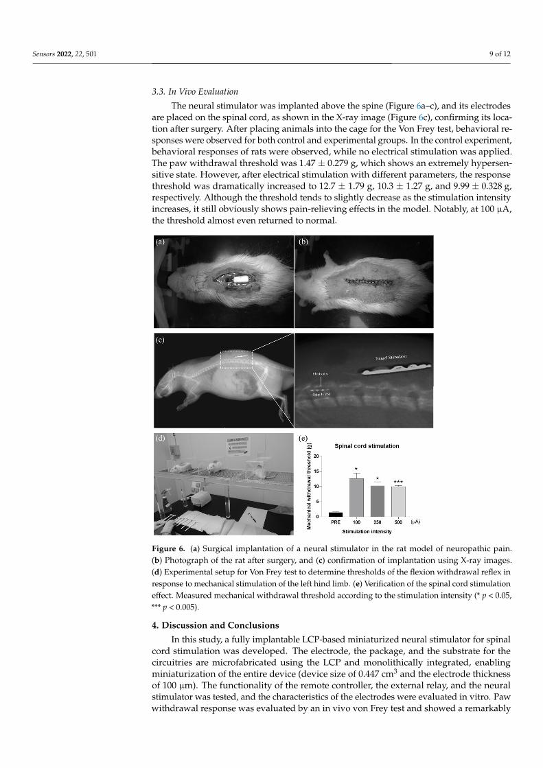
3.3. In Vivo Evaluation The neural stimulator was implanted above the spine (Figure 6a–c), and its electrodes
are placed on the spinal cord, as shown in the X-ray image (Figure 6c), confirming its location after surgery. After placing animals into the cage for the Von Frey test, behavioral responses were observed for both control and experimental groups. In the control exper-iment, behavioral responses of rats were observed, while no electrical stimulation was applied. The paw withdrawal threshold was 1.47 ± 0.279 g, which shows an extremely hypersensitive state. However, after electrical stimulation with different parameters, the response threshold was dramatically increased to 12.7 ± 1.79 g, 10.3 ± 1.27 g, and 9.99 ± 0.328 g, respectively. Although the threshold tends to slightly decrease as the stimulation
Figure 4. Exemplar waveform of the wireless operation of spinal cord stimulator and its stimulationcurrent pulse generation. The voltage measured across the (a) the transmitter coil and (b) the receivercoil; the output voltage at the (c) oscillator; and (d,e) stimulation generator ASIC.
Figure 5 shows the electrochemical characteristic of the stimulation electrodes. TheEIS measurement revealed that the average magnitude of the impedance at 1 kHz was1468 ± 333.3 Ω, whose value lies in the order of kiloohms, which is reasonable for theextracellular stimulation electrodes [32]. The average phase angle was −63 ± 4.3, indi-cating that a fabricated spinal cord electrode delivers charge via capacitive and faradaicprocesses. The charge storage capacity (CSC) of the fabricated electrodes was calculated as33.1 ± 13.4 µC/cm2.
Sensors 2022, 22, x FOR PEER REVIEW 9 of 12
intensity increases, it still obviously shows pain-relieving effects in the model. Notably, at 100 μA, the threshold almost even returned to normal.
Figure 5. Electrochemical characterization of the stimulation electrodes array. (a) Electrochemical impedance spectroscopy (EIS) measurements as represented by the mean (black line) and the stand-ard deviation (blue bar) of the (a) magnitude and the (b) phase angle of the impedance. The typical (c) cyclic voltammetry (CV).
Figure 6. (a) Surgical implantation of a neural stimulator in the rat model of neuropathic pain. (b) Photograph of the rat after surgery, and (c) confirmation of implantation using X-ray images. (d) Experimental setup for Von Frey test to determine thresholds of the flexion withdrawal reflex in response to mechanical stimulation of the left hind limb. (e) Verification of the spinal cord stimula-tion effect. Measured mechanical withdrawal threshold according to the stimulation intensity (* p < 0.05, *** p < 0.005).
Figure 5. Electrochemical characterization of the stimulation electrodes array. (a) Electrochemicalimpedance spectroscopy (EIS) measurements as represented by the mean (black line) and the standarddeviation (blue bar) of the (a) magnitude and the (b) phase angle of the impedance. The typical(c) cyclic voltammetry (CV).
Sensors 2022, 22, 501 9 of 12
3.3. In Vivo Evaluation
The neural stimulator was implanted above the spine (Figure 6a–c), and its electrodesare placed on the spinal cord, as shown in the X-ray image (Figure 6c), confirming its loca-tion after surgery. After placing animals into the cage for the Von Frey test, behavioral re-sponses were observed for both control and experimental groups. In the control experiment,behavioral responses of rats were observed, while no electrical stimulation was applied.The paw withdrawal threshold was 1.47 ± 0.279 g, which shows an extremely hypersen-sitive state. However, after electrical stimulation with different parameters, the responsethreshold was dramatically increased to 12.7 ± 1.79 g, 10.3 ± 1.27 g, and 9.99 ± 0.328 g,respectively. Although the threshold tends to slightly decrease as the stimulation intensityincreases, it still obviously shows pain-relieving effects in the model. Notably, at 100 µA,the threshold almost even returned to normal.
Sensors 2022, 22, x FOR PEER REVIEW 9 of 12
intensity increases, it still obviously shows pain-relieving effects in the model. Notably, at 100 μA, the threshold almost even returned to normal.
Figure 5. Electrochemical characterization of the stimulation electrodes array. (a) Electrochemical impedance spectroscopy (EIS) measurements as represented by the mean (black line) and the stand-ard deviation (blue bar) of the (a) magnitude and the (b) phase angle of the impedance. The typical (c) cyclic voltammetry (CV).
Figure 6. (a) Surgical implantation of a neural stimulator in the rat model of neuropathic pain. (b) Photograph of the rat after surgery, and (c) confirmation of implantation using X-ray images. (d) Experimental setup for Von Frey test to determine thresholds of the flexion withdrawal reflex in response to mechanical stimulation of the left hind limb. (e) Verification of the spinal cord stimula-tion effect. Measured mechanical withdrawal threshold according to the stimulation intensity (* p < 0.05, *** p < 0.005).
Figure 6. (a) Surgical implantation of a neural stimulator in the rat model of neuropathic pain.(b) Photograph of the rat after surgery, and (c) confirmation of implantation using X-ray images.(d) Experimental setup for Von Frey test to determine thresholds of the flexion withdrawal reflex inresponse to mechanical stimulation of the left hind limb. (e) Verification of the spinal cord stimulationeffect. Measured mechanical withdrawal threshold according to the stimulation intensity (* p < 0.05,*** p < 0.005).
4. Discussion and Conclusions
In this study, a fully implantable LCP-based miniaturized neural stimulator for spinalcord stimulation was developed. The electrode, the package, and the substrate for thecircuitries are microfabricated using the LCP and monolithically integrated, enablingminiaturization of the entire device (device size of 0.447 cm3 and the electrode thicknessof 100 µm). The functionality of the remote controller, the external relay, and the neuralstimulator was tested, and the characteristics of the electrodes were evaluated in vitro. Pawwithdrawal response was evaluated by an in vivo von Frey test and showed a remarkably

Sensors 2022, 22, 501 10 of 12
reduced pain response. The mechanical withdrawal threshold was increased after electricalstimulation, and it even brought them back to a normal state at the certain parameter,confirming the effectiveness of the spinal cord stimulation in pain control.
Our LCP-based spinal cord stimulator has several advantages over the conventionalones. The metal packaged conventional spinal cord stimulation system has a separate IPGand an electrode array, which are connected by the long lead wire. Due to their modularconfiguration, moisture can smear into the gap at the binding site of each module, shorten-ing the lifetime. However, since our device is monolithically fabricated and packaged byLCP having extremely low moisture absorption properties (<0.04%), we could eliminatethe moisture leakage path at the binding site of each module. When comparing LCP withother biocompatible polymers used to develop a neural probe, LCP offers lower moistureabsorption than others such as polyimide (2.8%) and parylene-C (0.06–0.6%) [25]. Thelong-term reliability of the LCP encapsulation including LCP-based electrode arrays andthe LCP packaging of electronics has been demonstrated in the previous studies. It wasfirst investigated in [31] as an encapsulation material of the microelectrode array for retinalimplants, resulting in 2 months of accelerated soak test at 75 C with no degradationin LCP–LCP adhesion, and 3 months of in vivo test in rabbit eyes with no chorioretinalinflammation. It was demonstrated as an encapsulation of the radio frequency integratedcircuit, showing stable RF characteristics in vivo for more than 40 days and an expecteddevice lifetime of more than 2 years in in vitro accelerated soak tests [33]. It was also testedas a base material of the monolithic retinal prosthesis. At least 8 years of the device lifetime(LCP–LCP interface, LCP–metal interface, and LCP surface permeation included) wasshown in in vitro accelerated soak tests, and stability in in vivo for 2.5 years [37]. Lastly,the chronic reliability of an encapsulation material of micro-electrocorticographic (µECoG)array was demonstrated, resulting in at least 3.4 years of lifetime in in vitro acceleratedsoak tests [38]. In addition, a fabrication method to enhance the adhesion of metal–polymerwas studied, showing 21% enhanced mean time to failure in in vitro tests [35].
Since the LCP-based electrodes are manufactured based on a semiconductor microfab-rication process, the electrode can be fabricated with high precision and easily customizedbased on the patients and applications. The LCP-based spinal cord stimulator can be readilyextended and utilized for a much wider range of implantable neural stimulator such asdeep-brain stimulation, brain–machine interface, and other sensory and motor prosthetics,opening a new avenue toward miniaturized polymer-based neural prosthetics.
Author Contributions: Conceptualization, S.Y. and S.J.K.; methodology, S.Y., C.S.K., J.S., S.S., M.P.,H.H.J., K.E., J.W.C. and S.J.K.; software, S.Y., C.S.K., J.S. and S.S.; validation, S.Y., C.S.K., J.S., S.S. andM.P.; formal analysis, S.Y., C.S.K., S.S., M.P., H.H.J., K.E., J.W.C. and S.J.K.; data curation, S.Y., C.S.K.,S.S. and M.P.; writing—original draft preparation, S.Y., C.S.K., S.S., M.P., H.H.J., K.E., J.W.C. andS.J.K.; writing—review and editing, S.Y., C.S.K., S.S., M.P., H.H.J., K.E., J.W.C. and S.J.K. All authorshave read and agreed to the published version of the manuscript.
Funding: This work was supported by the CABMC through funding by the Defense AcquisitionProgram Administration (UD170030ID) of Korea, by National Research Foundation of Korea (NRF)grant funded by the Korea government (MSIT) (2020R1C1C1010505, 2021R1I1A1A01047750), byBK21PLUS, Creative Human Resource Education and Research Programs for ICT Convergence in the4th Industrial Revolution, by Pusan National University Research 2021.
Institutional Review Board Statement: The Institutional Animal Care and Use Committee of YonseiUniversity (IACUC no. 2016-0161, date of approval 26 September 2016) approved the study.
Informed Consent Statement: Not applicable.
Data Availability Statement: Not applicable.
Conflicts of Interest: The authors declare no conflict of interest.

Sensors 2022, 22, 501 11 of 12
References1. Campbell, J.N.; Meyer, R.A. Mechanisms of Neuropathic Pain. Neuron 2006, 52, 77–92. [CrossRef]2. Broseta, J.; Barberá, J.; de Vera, J.A.; Barcia-Salorio, J.L.; Garcia-March, G.; González-Darder, J.; Rovaina, F.; Joanes, V. Spinal cord
stimulation in peripheral arterial disease: A cooperative study. J. Neurosurg. 1986, 64, 71–80. [CrossRef] [PubMed]3. Mushahwar, V.K.; Horch, K.W. Muscle recruitment through electrical stimulation of the lumbo-sacral spinal cord. IEEE Trans.
Rehabil. Eng. 2000, 8, 22–29. [CrossRef]4. Levy, R.; Henderson, J.; Slavin, K.; Simpson, B.A.; Barolat, G.; Shipley, J.; North, R. Incidence and Avoidance of Neurologic
Complications with Paddle Type Spinal Cord Stimulation Leads. Neuromodul. Technol. Neural Interface 2011, 14, 412–422. [CrossRef]5. Oakley, J.C.; Prager, J.P. Spinal Cord Stimulation: Mechanisms of Action. Spine 2002, 27, 2574–2583. [CrossRef]6. Sun, S.; Xu, Q.; Guo, C.; Guan, Y.; Liu, Q.; Dong, X. Leaky Gate Model: Intensity-Dependent Coding of Pain and Itch in the Spinal
Cord. Neuron 2017, 93, 840–853. [CrossRef]7. Mendell, L.M. Constructing and deconstructing the gate theory of pain. Pain 2014, 155, 201–216. [CrossRef] [PubMed]8. Melzack, R. Gate control theory: On the evolution of pain concepts. Pain Forum 1996, 5, 128–138. [CrossRef]9. Van Buyten, J.-P.; Al-Kaisy, A.; Smet, I.; Palmisani, S.; Smith, T. High-Frequency Spinal Cord Stimulation for the Treatment of
Chronic Back Pain Patients: Results of a Prospective Multicenter European Clinical Study. Neuromodul. Technol. Neural Interface2013, 16, 59–66. [CrossRef]
10. Kapural, L.; Yu, C.; Doust, M.W.; Gliner, B.E.; Vallejo, R.; Sitzman, B.T.; Amirdelfan, K.; Morgan, D.M.; Brown, L.L.; Yearwood, T.L.;et al. Novel 10-kHz High-frequency Therapy (HF10 Therapy) Is Superior to Traditional Low-frequency Spinal Cord Stimulationfor the Treatment of Chronic Back and Leg Pain: The SENZA-RCT Randomized Controlled Trial. Anesthesiology 2015, 123,851–860. [CrossRef]
11. Lempka, S.F.; Zander, H.J.; Anaya, C.J.; Wyant, A.; Ozinga IV, J.G.; Machado, A.G. Patient-Specific Analysis of Neural ActivationDuring Spinal Cord Stimulation for Pain. Neuromodul. Technol. Neural Interface 2020, 23, 572–581. [CrossRef]
12. Yakovlev, A.E.; Ellias, Y. Spinal cord stimulation as a treatment option for intractable neuropathic cancer pain. Clin. Med. Res.2008, 6, 103–106. [CrossRef]
13. PRIMEADVANCEDTM Multi-Program Neurostimulator Implant Manual. Available online: http://www.neuromodulation.ch/sites/default/files/pictures/prime_advanced_implant_manual.pdf (accessed on 26 September 2021).
14. PrecisionTM M8 Adapter—Directions for Use. Available online: https://www.bostonscientific.com/content/dam/Manuals/us/current-rev-en/90893429-09RevA_Precision_M8_Adapter_DFU_en-US_S.pdf (accessed on 26 September 2021).
15. He, J.; Barolat, G.; Holsheimer, J.; Struijk, J.J. Perception threshold and electrode position for spinal cord stimulation. Pain 1994,59, 55–63. [CrossRef]
16. De Ridder, D.; Plazier, M.; Kamerling, N.; Menovsky, T.; Vanneste, S. Burst Spinal Cord Stimulation for Limb and Back Pain.World Neurosurg. 2013, 80, 642–649. [CrossRef]
17. Physician Implant Manual 11051 Rev A. Available online: https://www.accessdata.fda.gov/cdrh_docs/pdf13/P130022d.pdf(accessed on 26 September 2021).
18. Al-Kaisy, A.; Van Buyten, J.-P.; Smet, I.; Palmisani, S.; Pang, D.; Smith, T. Sustained Effectiveness of 10 kHz High-FrequencySpinal Cord Stimulation for Patients with Chronic, Low Back Pain: 24-Month Results of a Prospective Multicenter Study. PainMed. 2014, 15, 347–354. [CrossRef] [PubMed]
19. Rabi, J.; Anitescu, M. Late Extrusion of an Implantable Pulse Generator of a Spinal Cord Stimulator. Pain Physician 2016, 19,E671-4. [PubMed]
20. Resurreccion, F.P.; Bohrer, T.H. Shielding and field modification of thick metal films. In Woodhead Publishing in Materials; Lorence,M.W., Pesheck, P.S., Eds.; Woodhead Publishing: Sawston, UK, 2020; pp. 293–330. ISBN 978-0-08-102713-4.
21. Lee, H.-C.; Kim, J.-Y.; Noh, C.-H.; Song, K.Y.; Cho, S.-H. Selective metal pattern formation and its EMI shielding efficiency. Appl.Surf. Sci. 2006, 252, 2665–2672. [CrossRef]
22. Nyenhuis, J.A.; Park, S.-M.; Kamondetdacha, R.; Amjad, A.; Shellock, F.G.; Rezai, A.R. MRI and implanted medical devices: Basicinteractions with an emphasis on heating. IEEE Trans. Device Mater. Reliab. 2005, 5, 467–480. [CrossRef]
23. Mattei, E.; Calcagnini, G.; Censi, F.; Triventi, M.; Bartolini, P. Numerical Model for Estimating RF-Induced Heating on a PacemakerImplant During MRI: Experimental Validation. IEEE Trans. Biomed. Eng. 2010, 57, 2045–2052. [CrossRef]
24. Miyata, K.; Hasegawa, M.; Abe, Y.; Tabuchi, T.; Namiki, T.; Ishigami, T. Radiofrequency heating and magnetically induceddisplacement of dental magnetic attachments during 3.0 T MRI. Dentomaxillofac. Radiol. 2012, 41, 668–674. [CrossRef] [PubMed]
25. Jeong, J.; Lee, S.W.; Min, K.S.; Shin, S.; Jun, S.B.; Kim, S.J. Liquid crystal polymer (LCP), an attractive substrate for retinal implant.Sens. Mater. 2012, 24, 189–203.
26. Jayaraj, K.; Noll, T.E.; Blizard, K.G. Controlled thermal expansion printed wiring boards based on liquid crystal polymerdielectrics. Circuit World 1994, 22, 25–30. [CrossRef]
27. Jayaraj, K.; Noll, T.E.; Singh, D.R. A low cost multichip packaging technology for monolithic microwave integrated circuits. IEEETrans. Antennas Propag. 1995, 43, 992–997. [CrossRef]
28. Kim, J.H.; Min, K.S.; Jeong, J.S.; Kim, S.J. Challenges for the Future Neuroprosthetic Implants B. In Proceedings of the 5th EuropeanConference of the International Federation for Medical and Biological Engineering; Jobbágy, Á., Ed.; Springer: Berlin/Heidelberg,Germany, 2012; pp. 1214–1216.

Sensors 2022, 22, 501 12 of 12
29. Lee, S.E.; Jun, S.B.; Lee, H.J.; Kim, J.; Lee, S.W.; Im, C.; Shin, H.; Chang, J.W.; Kim, S.J. A Flexible Depth Probe Using Liquid CrystalPolymer. IEEE Trans. Biomed. Eng. 2012, 59, 2085–2094.
30. Shin, S.; Kim, J.; Jeong, J.; Gwon, T.M.; Choi, G.J.; Lee, S.E.; Kim, J.; Jun, S.B.; Chang, J.W.; Kim, S.J. High charge storage capacityelectrodeposited iridium oxide film on liquid crystal polymer-based neural electrodes. Sens. Mater. 2016, 28, 243–260.
31. Lee, S.W.; Seo, J.-M.; Ha, S.; Kim, E.T.; Chung, H.; Kim, S.J. Development of Microelectrode Arrays for Artificial Retinal ImplantsUsing Liquid Crystal Polymers. Investig. Ophthalmol. Vis. Sci. 2009, 50, 5859–5866. [CrossRef]
32. Jeong, J.; Bae, S.H.; Min, K.S.; Seo, J.-M.; Chung, H.; Kim, S.J. A Miniaturized, Eye-Conformable, and Long-Term Reliable RetinalProsthesis Using Monolithic Fabrication of Liquid Crystal Polymer (LCP). IEEE Trans. Biomed. Eng. 2015, 62, 982–989. [CrossRef]
33. Hwang, G.-T.; Im, D.; Lee, S.E.; Lee, J.; Koo, M.; Park, S.Y.; Kim, S.; Yang, K.; Kim, S.J.; Lee, K.; et al. In Vivo Silicon-Based FlexibleRadio Frequency Integrated Circuits Monolithically Encapsulated with Biocompatible Liquid Crystal Polymers. ACS Nano 2013,7, 4545–4553. [CrossRef]
34. Shim, S.; Yun, S.; Kim, S.; Choi, G.J.; Baek, C.; Jang, J.; Jung, Y.; Sung, J.; Park, J.H.; Seo, K.; et al. A handheld neural stimulationcontroller for avian navigation guided by remote control. Biomed. Mater. Eng. 2019, 30, 497–507. [CrossRef] [PubMed]
35. Seo, J.; Wee, J.H.; Park, J.H.; Park, P.; Kim, J.-W.; Kim, S.J. Nerve cuff electrode using embedded magnets and its application tohypoglossal nerve stimulation. J. Neural Eng. 2016, 13, 66014. [CrossRef] [PubMed]
36. Decosterd, I.; Woolf, C.J. Spared nerve injury: An animal model of persistent peripheral neuropathic pain. Pain 2000, 87,149–158. [CrossRef]
37. Jeong, J.; Hyun Bae, S.; Seo, J.-M.; Chung, H.; June Kim, S. Long-term evaluation of a liquid crystal polymer (LCP)-based retinalprosthesis. J. Neural Eng. 2016, 13, 25004. [CrossRef]
38. Woods, V.; Trumpis, M.; Bent, B.; Palopoli-Trojani, K.; Chiang, C.-H.; Wang, C.; Yu, C.; Insanally, M.N.; Froemke, R.C.; Viventi, J.Long-term recording reliability of liquid crystal polymer µECoG arrays. J. Neural Eng. 2018, 15, 66024. [CrossRef]
Copyright © 2022 FDOKUMEN