Miniature implantable antennas for biomedical telemetry: From simulation to realization
8
3140 IEEE TRANSACTIONS ON BIOMEDICAL ENGINEERING, VOL. 59, NO. 11, NOVEMBER 2012 Miniature Implantable Antennas for Biomedical Telemetry: From Simulation to Realization Asimina Kiourti ∗ , Student Member, IEEE, Jorge R. Costa, Senior Member, IEEE, Carlos A. Fernandes, Senior Member, IEEE, Andr´ e G. Santiago, and Konstantina S. Nikita, Senior Member, IEEE Abstract—We address numerical versus experimental design and testing of miniature implantable antennas for biomedical telemetry in the medical implant communications service band (402–405 MHz). A model of a novel miniature antenna is initially proposed for skin implantation, which includes varying parame- ters to deal with fabrication-specific details. An iterative design- and-testing methodology is further suggested to determine the pa- rameter values that minimize deviations between numerical and experimental results. To assist in vitro testing, a low-cost technique is proposed for reliably measuring the electric properties of liquids without requiring commercial equipment. Validation is performed within a specific prototype fabrication/testing approach for minia- ture antennas. To speed up design while providing an antenna for generic skin implantation, investigations are performed inside a canonical skin-tissue model. Resonance, radiation, and safety per- formance of the proposed antenna is finally evaluated inside an anatomical head model. This study provides valuable insight into the design of implantable antennas, assessing the significance of fabrication-specific details in numerical simulations and uncer- tainties in experimental testing for miniature structures. The pro- posed methodology can be applied to optimize antennas for several fabrication/testing approaches and biotelemetry applications. Index Terms—Biomedical telemetry, dielectric measurements, implantable antenna, in vitro, medical implant communications service (MICS) band. I. INTRODUCTION W IRELESS antenna telemetry for implantable biomedi- cal devices is recently receiving considerable attention for diagnosis and therapy [1]–[5]. Bidirectional communication between the implanted device and exterior monitoring/control Manuscript received February 14, 2012; revised April 5, 2012; accepted May 25, 2012. Date of publication June 5, 2012; date of current version October 16, 2012. This work was supported in part by the Fundac ¸˜ ao para a Ciˆ encia e Tec- nologia, Portugal, under Project RFID Local PTDC/EEA-TEL/102390/2008. The work of A.K. was supported by the IEEE Antennas and Propagation Soci- ety Doctoral Research Award. Asterisk indicates corresponding author. ∗ A. Kiourti is with the School of Electrical and Computer Engineering and the Institute of Communications and Computer Systems, National Technical University of Athens, Athens 15780, Greece (e-mail: [email protected]). J. R. Costa is with the Instituto de Telecomunicac ¸˜ oes and the Departamento de Ciˆ encias e Tecnologias da Informac ¸˜ ao, Instituto Universit´ ario de Lisboa (ISCTE-IUL), Lisboa 1649-026, Portugal (e-mail: [email protected]). C. A. Fernandes is with Instituto de Telecomunicac ¸˜ oes and the Instituto Superior T´ ecnico, Technical University of Lisbon, Lisboa 1049-001, Portugal (e-mail: [email protected]). A. G. Santiago is with Instituto Superior T´ ecnico, Technical University of Lisbon, Lisboa 1049-001, Portugal (e-mail: [email protected]). K. S. Nikita is with the School of Electrical and Computer Engineering and the Institute of Communications and Computer Systems, National Technical University of Athens, Athens 15780, Greece (e-mail: [email protected]). Color versions of one or more of the figures in this paper are available online at http://ieeexplore.ieee.org. Digital Object Identifier 10.1109/TBME.2012.2202659 equipment is most commonly performed in the medical implant communications service (MICS) band (402–405 MHz), which is regulated by the United States Federal Communications Com- mission [6] and the European Radiocommunications Commit- tee [7]. Patch designs are preferred for implant-integrated an- tennas because of their flexibility in design, conformability, and shape [8]. Design of implantable patch antennas operating in the low- frequency MICS band draws high-scientific interest to deal with miniaturization. The aim is to decrease the antenna physical size, while increasing its electrical size. Rectangular 10240 and 5760 mm 3 chest-implantable antennas have been reported [1], which use the high-permittivity (ε r = 10.2) Rogers 3210 di- electric and apply a spiral radiator for size reduction. Addition of a shorting pin, thus, conversion to a planar inverted-F an- tenna (PIFA) acts like a ground plane on a monopole, and has been found to shrink the volume of the aforementioned anten- nas by 40% and 60%, respectively [1]. Other MICS implantable antennas applying similar miniaturization techniques include a 3457 mm 3 PIFA with a serpentine radiator built on MACOR substrate (ε r = 6.1) [8], and a 6480 mm 3 antenna with a waffle-type radiator built on silicon substrate (ε r = 3.1) [9], both intended for generic body implantation (2/3 human muscle properties used to represent average body properties). Multi- layer structures including vertically stacked radiating patches increase the length of the current flow and further assist in miniaturization. Reported skin-implantable stacked PIFAs oc- cupy miniaturized volumes of 598 [10], 383 [11], 337 [12], and 32.7 mm 3 [5], [13]. Biocompatibility issues entail the use of a superstrate for all structures, while gain degradation with size reduction must also be considered. Numerical models of implantable patch antennas proposed in the literature are generally simplified; zero-thickness perfectly conducting sheet model for the radiating and ground planes, glue used to bond the layers together is not taken into account, while ideal models of 50 Ω coaxial cables are used to feed the structures. Most studies report reflection coefficient measure- ments (e.g., [1], [2], [8]–[11]) without assessing the effect of fabrication/testing details on the resonance of the simplified an- tenna or discussing design refinements required to restore the desired performance. Only influence of the feeding network has been discussed for patch implantable antennas [14]; however, no design modifications were suggested to overcome its effects in antenna resonance. Preliminary investigations on metallization, gluing, and feeding considerations in numerical design have recently been reported for 3-D cylindrical antennas [15]. As the antenna dimensions shrink, the effect of fabrication issues becomes even more critical. 0018-9294/$31.00 © 2012 IEEE
Transcript of Miniature implantable antennas for biomedical telemetry: From simulation to realization

3140 IEEE TRANSACTIONS ON BIOMEDICAL ENGINEERING, VOL. 59, NO. 11, NOVEMBER 2012
Miniature Implantable Antennas for BiomedicalTelemetry: From Simulation to Realization
Asimina Kiourti∗, Student Member, IEEE, Jorge R. Costa, Senior Member, IEEE,Carlos A. Fernandes, Senior Member, IEEE, Andre G. Santiago, and Konstantina S. Nikita, Senior Member, IEEE
Abstract—We address numerical versus experimental designand testing of miniature implantable antennas for biomedicaltelemetry in the medical implant communications service band(402–405 MHz). A model of a novel miniature antenna is initiallyproposed for skin implantation, which includes varying parame-ters to deal with fabrication-specific details. An iterative design-and-testing methodology is further suggested to determine the pa-rameter values that minimize deviations between numerical andexperimental results. To assist in vitro testing, a low-cost techniqueis proposed for reliably measuring the electric properties of liquidswithout requiring commercial equipment. Validation is performedwithin a specific prototype fabrication/testing approach for minia-ture antennas. To speed up design while providing an antenna forgeneric skin implantation, investigations are performed inside acanonical skin-tissue model. Resonance, radiation, and safety per-formance of the proposed antenna is finally evaluated inside ananatomical head model. This study provides valuable insight intothe design of implantable antennas, assessing the significance offabrication-specific details in numerical simulations and uncer-tainties in experimental testing for miniature structures. The pro-posed methodology can be applied to optimize antennas for severalfabrication/testing approaches and biotelemetry applications.
Index Terms—Biomedical telemetry, dielectric measurements,implantable antenna, in vitro, medical implant communicationsservice (MICS) band.
I. INTRODUCTION
W IRELESS antenna telemetry for implantable biomedi-cal devices is recently receiving considerable attention
for diagnosis and therapy [1]–[5]. Bidirectional communicationbetween the implanted device and exterior monitoring/control
Manuscript received February 14, 2012; revised April 5, 2012; accepted May25, 2012. Date of publication June 5, 2012; date of current version October 16,2012. This work was supported in part by the Fundacao para a Ciencia e Tec-nologia, Portugal, under Project RFID Local PTDC/EEA-TEL/102390/2008.The work of A.K. was supported by the IEEE Antennas and Propagation Soci-ety Doctoral Research Award. Asterisk indicates corresponding author.
∗A. Kiourti is with the School of Electrical and Computer Engineering andthe Institute of Communications and Computer Systems, National TechnicalUniversity of Athens, Athens 15780, Greece (e-mail: [email protected]).
J. R. Costa is with the Instituto de Telecomunicacoes and the Departamentode Ciencias e Tecnologias da Informacao, Instituto Universitario de Lisboa(ISCTE-IUL), Lisboa 1649-026, Portugal (e-mail: [email protected]).
C. A. Fernandes is with Instituto de Telecomunicacoes and the InstitutoSuperior Tecnico, Technical University of Lisbon, Lisboa 1049-001, Portugal(e-mail: [email protected]).
A. G. Santiago is with Instituto Superior Tecnico, Technical University ofLisbon, Lisboa 1049-001, Portugal (e-mail: [email protected]).
K. S. Nikita is with the School of Electrical and Computer Engineering andthe Institute of Communications and Computer Systems, National TechnicalUniversity of Athens, Athens 15780, Greece (e-mail: [email protected]).
Color versions of one or more of the figures in this paper are available onlineat http://ieeexplore.ieee.org.
Digital Object Identifier 10.1109/TBME.2012.2202659
equipment is most commonly performed in the medical implantcommunications service (MICS) band (402–405 MHz), whichis regulated by the United States Federal Communications Com-mission [6] and the European Radiocommunications Commit-tee [7]. Patch designs are preferred for implant-integrated an-tennas because of their flexibility in design, conformability, andshape [8].
Design of implantable patch antennas operating in the low-frequency MICS band draws high-scientific interest to deal withminiaturization. The aim is to decrease the antenna physicalsize, while increasing its electrical size. Rectangular 10240 and5760 mm3 chest-implantable antennas have been reported [1],which use the high-permittivity (εr = 10.2) Rogers 3210 di-electric and apply a spiral radiator for size reduction. Additionof a shorting pin, thus, conversion to a planar inverted-F an-tenna (PIFA) acts like a ground plane on a monopole, and hasbeen found to shrink the volume of the aforementioned anten-nas by 40% and 60%, respectively [1]. Other MICS implantableantennas applying similar miniaturization techniques include a3457 mm3 PIFA with a serpentine radiator built on MACORsubstrate (εr = 6.1) [8], and a 6480 mm3 antenna with awaffle-type radiator built on silicon substrate (εr = 3.1) [9],both intended for generic body implantation (2/3 human muscleproperties used to represent average body properties). Multi-layer structures including vertically stacked radiating patchesincrease the length of the current flow and further assist inminiaturization. Reported skin-implantable stacked PIFAs oc-cupy miniaturized volumes of 598 [10], 383 [11], 337 [12], and32.7 mm3 [5], [13]. Biocompatibility issues entail the use of asuperstrate for all structures, while gain degradation with sizereduction must also be considered.
Numerical models of implantable patch antennas proposed inthe literature are generally simplified; zero-thickness perfectlyconducting sheet model for the radiating and ground planes,glue used to bond the layers together is not taken into account,while ideal models of 50 Ω coaxial cables are used to feed thestructures. Most studies report reflection coefficient measure-ments (e.g., [1], [2], [8]–[11]) without assessing the effect offabrication/testing details on the resonance of the simplified an-tenna or discussing design refinements required to restore thedesired performance. Only influence of the feeding network hasbeen discussed for patch implantable antennas [14]; however, nodesign modifications were suggested to overcome its effects inantenna resonance. Preliminary investigations on metallization,gluing, and feeding considerations in numerical design haverecently been reported for 3-D cylindrical antennas [15]. Asthe antenna dimensions shrink, the effect of fabrication issuesbecomes even more critical.
0018-9294/$31.00 © 2012 IEEE

IEEE TRANSACTIONS ON BIOMEDICAL ENGINEERING, VOL. 59, NO. 11, NOVEMBER 2012 3141
In this paper, the first challenge lies in proposing a noveldesign-and-testing methodology that optimizes the design ofsimplified implantable antennas to suit-specific prototype fabri-cation approaches. Antenna design is optimized based on quasi-Newton optimization [16] to address metallization, gluing, andfeeding considerations, while sensitivity tests are performed todetermine the maximum allowable deviations between numeri-cal and experimental results. A low-cost technique is further sug-gested for reliably measuring the electric properties of (tissue-simulating) liquids without the use of commercial equipment.
The second challenge lies in dealing with prototype fabri-cation of miniature antennas for which tolerance to fabricationissues (e.g., soldering bumps, uncertainties in glue thickness andpermittivity, etc.) is considered to be highly critical. A paramet-ric model of a novel miniature antenna is proposed for skin im-plantation, and the design-and-testing methodology is applied tooptimally adjust it within a specific fabrication/testing approach,for validation purposes. To speed up design while providing anantenna model for generic skin implantation (e.g., inside thehead, arm, and trunk for intracranial pressure, blood pressure,and glucose monitoring, respectively [17]), investigations areperformed inside a canonical skin-tissue model. Antenna per-formance is finally evaluated inside an anatomical head model(e.g., pressure monitoring, brain wave sensing, stroke rehabili-tation, etc.).
An attempt is, thus, made to gain valuable insight into pro-totype fabrication and testing considerations that need to beconsidered within simulations for miniature implantable patchantennas. Although skin implantation in the MICS band is em-phasized, the proposed methodology can easily be applied tooptimize antennas for several other implantation scenarios andoperation frequencies [18], [19]. This paper is organized as fol-lows. Section II describes the proposed methods and models.Validation is performed in Section III. Numerical results insidean anatomical head model are presented in Section IV. Thispaper concludes in Section V.
II. MODELS AND METHODS
A. Tissue Models and Numerical Methods
To speed up simulations while providing a generic skin-implantable antenna, design and testing are performed insidea canonical skin-tissue model [see Fig. 1(a)] [5], [17]. The di-mensions are those of a typical semifilled plastic drinking glass,while the antenna is considered to be immersed by 2 cm. An-tenna resonance has been found to be almost insensitive to theshape of the tissue model, as long as it is surrounded by skin-tissue. Finite element (FE) simulations are carried out usingthe commercial software Ansoft HFSS [20]. The FE solver per-forms iterative tetrahedron-meshing refinement automaticallywith the mesh being perturbed by 30% between each pass. Themesh refinement procedure stops when the maximum changein the reflection coefficient magnitude (|S11 |) between two con-secutive passes is less than 0.02 or when the number of passesexceeds 10.
Performance of the antenna is further examined inside a 13-tissue (see Table I) anatomical head model [see Fig. 1(b)] [5].
Fig. 1. Tissue models: (a) typical semi-filled plastic drinking glass and(b) 13-tissue anatomical human head.
TABLE ITISSUE ELECTRIC PROPERTIES AT 402 MHZ AND MASS DENSITIES
The antenna is implanted 3.6 mm under the skin, with its groundplane being placed in parallel with the horizontal plane of thehead model. Finite-difference time-domain (FDTD) simulationsare carried out in Remcom XFDTD [21], which enables efficientmodeling of anatomical body parts. The antenna and anatomicalhead are modeled in 0.1 and 3.66 mm3 cells. Cells of 5 mm inedge (Δx) model free space so as to meet the FDTD spatialstep constraint (Δx) < λmin /10, where λmin indicates the wave-length of the highest frequency of interest) for the simulationset up under consideration. This sets the maximum simulationfrequency fmax to 6 GHz (fmax < c/(10Δx), where c is the speedof light), and the time step Δt to 9.622 ps (Δt = Δx/c
√3), as
referenced to free space. Meshing is adaptive to avoid abrupttransitions. A sinusoidal and a Gaussian source (pulse width of32 time steps) are used in the single-frequency and broadbandsimulations. Calculations continue up to a 30 dB convergence.
Absorbing boundaries are set λ0 /4 (λ0 is the free-space wave-length, f0 = 402 MHz) away from all simulation setups in orderto extend radiation infinitely far, while guaranteeing stability ofthe numerical calculations [20], [21]. Tissue electric propertiesat 402 MHz are considered (see Table I [22]), and approximatedas constant inside the 300–500 MHz frequency range [5]. Tissuemass densities are also provided in Table I.
B. Parametric Antenna Model
A parametric model of a miniature stacked PIFA is proposedfor skin implantation, as shown in Fig. 2.
Corresponding dimensions are indicated in Table II for a sim-plified antenna (simplified), an optimized antenna considering

3142 IEEE TRANSACTIONS ON BIOMEDICAL ENGINEERING, VOL. 59, NO. 11, NOVEMBER 2012
Fig. 2. Proposed parametric antenna model: (a) ground plane, (b) lower patch,(c) upper patch, and (d) side view.
TABLE IIVARIABLE VALUES OF THE PROPOSED SIMPLIFIED, FABRICATION-SPECIFIC AND
HEAD-TUNED ANTENNAS (IN mm)
specific fabrication issues (fabrication-specific), and a fine-tuned version of the simplified antenna inside the anatomicalhead model of Fig. 1(b) (head-tuned). Circular shape is chosento avoid sharp edges, while the origin of the coordinate system isconsidered to be located at the center of the PIFA ground plane.The model consists of a 6 mm-radius ground plane and twoRp -radius vertically stacked, meandered patches. Copper sheetswith a thickness of hm are considered for the ground, lower, andupper patches. Both patches are fed by an L-length, 50 Ω-coaxialcable (F: x = 0 mm, y = 4 mm), and radiate. Each one is printedon a 0.635 mm substrate (lower/upper), while a 0.635-mm su-perstrate covers the structure to preserve its biocompatibilityand robustness. Rogers 3210 (εr = 10.2, tanδ = 0.003), whichhas long been used in implantable antennas [1], [2], [10]–[12]is chosen as the dielectric material. Glue layers (εr = εrg ) witha thickness of hg bond the dielectric layers together. Meandersare equidistant by 1 mm, and their lengths are denoted by thex coordinate xij , where the subscripts {ij: i = A–F, and j =L, U} identify the meander in Fig. 2(b) and (c). Their width isdesigned to be small (0.4 mm) so as to maximize the area of thepatch for radiation. A 0.3 mm-radius shorting pin (S: x = 1 mm,y = –4 mm) connects the ground plane with the lower patch forfurther miniaturization.
TABLE IIIEFFECT OF METALLIZATION, GLUING, AND FEEDING ON THE RESONANCE
OF THE PROPOSED SIMPLIFIED ANTENNA
The simplified version of the parametric antenna model ex-hibits zero thickness, perfect electric ground- and patch-planes,ignores the presence of glue, and is fed by a simplified L =1 mm, 50 Ω-coaxial cable (inner and outer conductors modeledas a perfect conductor cylinder and a zero-thickness perfect con-ducting sheet, respectively). Variable values shown in Table IIunder “simplified” are found to achieve a reflection coefficientmagnitude (|S11 |) of better than –25 dB in the MICS band.The effects of metallization (hm ), gluing (εrg , hg ,) and feeding(coax type, L) are shown in Table III. Resonance characteris-tics are recorded, i.e., the exhibited resonance frequency fr es
and |S11@fres |. Gluing is found to be the most critical factor;low-permittivity glue layers isolate the high-permittivity sub-strate layers, thus decreasing the effective dielectric constantand electrical length of the antenna, while increasing its reso-nance frequency.
In a realistic prototype fabrication scenario, the metallization(hm ), gluing (εrg , hg ,), and feeding (coax type, L) variablesare set by the fabrication approach under consideration. Tuningthe Rp and xij variables alters the effective dimensions of theantenna and helps achieve the desired resonance characteristics[23].
C. Design-and-Testing Methodology
An iterative design-and-testing methodology is proposed forimplantable antennas, as summarized in Fig. 3. The basic ideais to optimize numerical antenna design for a specific prototypefabrication procedure and in vitro testing setup.
The simplified version of the parametric antenna model isinitially optimized to address fabrication limitations and obtainthe fabrication-specific antenna. Metallization (hm ), gluing (εrg ,hg ), and feeding (coax type, L) variables are set to the valuesspecified by the fabrication approach under consideration. Therest of the variables (Rp , xij ) are considered as dimensions inthe solution space and are optimized based on quasi-Newtonoptimization [16]. These are initialized to the values of thesimplified antenna and vary within the range [5.0 mm, 5.9 mm](Rp ) and [–(Rp – 0.3 mm), (Rp – 0.3 mm)] (xij ). The minimumand maximum step values are set to 0.1 and 0.4 mm, respectively.The cost function is defined as the magnitude of the reflection

IEEE TRANSACTIONS ON BIOMEDICAL ENGINEERING, VOL. 59, NO. 11, NOVEMBER 2012 3143
Fig. 3. Proposed design-and-testing methodology for implantable antennas.
coefficient at the desired resonance frequency of 402 MHz
cost = |S11@402 MHz |. (1)
Since the goal is to improve antenna resonance around 402 MHz,without aimlessly delaying design, the optimization process ter-minates when (1) is minimized, or when the number of iterationsexceeds 300.
Numerical sensitivity tests are subsequently performed in or-der to assess uncertainties that may be introduced within the invitro testing of the fabrication-specific antenna. The effect ofminor modifications in the most sensitive antenna design andtesting parameters is examined, as imposed by the fabricationapproach and measurement setup under consideration. Once theprototype antenna is fabricated and tested, sensitivity tests de-termine the maximum allowable deviation between numericaland experimental results, and the potential need for further re-finement in numerical antenna design. Deviations within theacceptable limits mean that the final prototype antenna has beenobtained.
D. Measurement of the Electric Properties of Liquids
In vitro testing of implantable antennas inside tissue-simulating liquids requires experimental measurement of theexhibited electric properties (εr , σ) to ensure conformancewith the numerical values [22]. There exist commercial com-plex permittivity measurement systems (e.g., Agilent Technolo-gies 85071E); however, alternative approaches are solicited forlaboratories that are not equipped with such systems. A novellow-cost and reliable complex permittivity measurement tech-nique is hereafter described and evaluated. To enhance confi-
Fig. 4. (a) Coaxial container for complex permittivity measurement of liquidmaterials and (b) numerical model.
dence in measurements, the technique is both reflection- andtransmission-based rather than solely reflection-based, as is theusually reported case (e.g., [24] and [25]).
The measurement setup consists of a parallelepiped containerintercepted by the inner conductor of a coaxial cable, as shownin Fig. 4(a). The arrangement corresponds to a coaxial con-tainer that can be filled with any liquid dielectric material. Itsdimensions (exterior container of 52 mm × 32 mm × 32.2 mm,interior cavity of 40 mm × 20 mm × 20 mm) have been chosenso as to place a resonance mode around the desired measuringbandwidth of 300–500 MHz when filled with a high-permittivityliquid. After closing the container lid, the structure representsa transition between coaxial guides with a step characteristicimpedance discontinuity. The transfer function between the twocoaxial connectors outside the container depends upon the com-plex permittivity of the container’s filling liquid. This can bede-embedded by comparing the measured scattering-matrix (S-matrix) with FE simulation results for the same structure. Thesimulation model is shown in Fig. 4(b), and is fine-tuned throughexperimental measurements for the empty (closed) container. Inthe case of nonhomogeneous mixtures, the present approachprovides inherently an average permittivity value. The liquid isassumed to fill the inner volume of the container completely.
To validate the proposed experimental technique, measure-ments are carried out considering the container to be filled witha liquid with well-known properties, i.e., distilled water. In thesimulations, the complex relative permittivity of distilled wateris approximated by the Debye model as a function of frequency
ε = ε′r − jε′′r = ε∞ +εs − ε∞1 + jωτ
(2)
where ε∞ = 4.6 is the optical permittivity at high frequencies,εs = 78.3 is the static permittivity at low frequencies, and τ= 8.07 ps is the electrical relaxation time [25]. Numerical andexperimental results are superimposed in Fig. 5 indicating quitegood agreement.
III. VALIDATION
Validation of the proposed design-and-testing methodologyis performed within the framework of a specific fabricationprocess, as dictated by the available materials, assembling tools,and technical expertise/experience.
A. Prototype Fabrication Approach
Standard 0.017 mm-thick electrodeposited copper foil cov-ers both sides of Rogers 3210. The sheets are etched using a

3144 IEEE TRANSACTIONS ON BIOMEDICAL ENGINEERING, VOL. 59, NO. 11, NOVEMBER 2012
Fig. 5. Results for the coaxial container filled with distilled water: (a) magni-tude of S11 (|S11 |), (b) phase of S11 (wrapped), (c) magnitude of S21 (|S21 |),and (d) phase of S21 (wrapped).
Fig. 6. Simulated and measured reflection coefficient frequency response ofthe simplified and fabrication-specific antennas.
photolithographic process. The lower substrate layer containsthe ground plane and the lower patch, the upper substrate con-tains the upper patch, and the superstrate has no metallization.Sprayable glue 3M 77 is used to bond the three layers (εr = 2),which is found to exhibit an average thickness of 0.3 mm forthe specific fabrication process. The antenna is fed through a 50mm-long EZ-47 semi-rigid coaxial cable.
B. Validation
1) Fabrication-Specific Antenna: Metallization (hm ), glu-ing (εrg , hg ,), and feeding (coaxial type, L) variables are setto the values imposed by the available fabrication approach,while the Rp and xij variables are optimized accordingly. Pa-rameter values shown in Table II under “fabrication-specific”are found to tune the fabrication-specific antenna at 402 MHzwith a wide 10 dB bandwidth (defined at | S11 | < –10 dB)of 44 MHz covering the MICS band. Radii of the patches andmeander lengths are significantly increased as compared to thesimplified antenna. The aim is to counteract the increase in res-onance frequency imposed by the low-permittivity glue layers.The simulated reflection coefficient frequency responses of thesimplified and fabrication-specific antennas are shown in Fig. 6.
2) Sensitivity Tests: Sensitivity test results related to antennadesign and experimental phantom uncertainties are indicated inFigs. 7 and 8, respectively. Only the antenna or phantom parame-ter under investigation is considered variable in each case, whileall other parameters are kept constant and equal to those of thefabrication-specific antenna design (see Table II, fabrication-
Fig. 7. Sensitivity test results (fres , |S11@ fres |) related to prototype antennaparameters: (a) gluing (εr g , hg ), (b) antenna radius (Rant ), (c) rotation of thelower (ϕl ) and upper (ϕu ) patches, and (d) permittivity of the Rogers 3210dielectric material, (εr diel ).
Fig. 8. Sensitivity test results (fres , |S11@ fres |) related to phantom parameters:(a) permittivity εr liq and conductivity σ liq of the skin-emulating liquid and(b) relative shift of the phantom from its original position (mx , my , mz ).
specific) and of the theoretical tissue model [see Fig. 1(a)].Resonance characteristics including the resonance frequencyfres and |S11@fres | are recorded, while the performance of thefabrication-specific antenna is also shown for reference. Giventhe fabrication approach described in Section III-A, the follow-ing parameters are identified as potential sources of experimen-tal uncertainties, and examined.
� Gluing (εrg , hg ) [see Fig. 7(a)]. Air bubbles accumulatingwithin the glue prevent εrg from being accurately deter-mined. Furthermore, the adopted layer bonding processdoes not allow fine control of hg . This is impaired not onlyby the glue itself, but also by the slight bump of the mi-crosolder near the coaxial cable and the shorting pin thatprevents perfect contact between the layers. Deviations of±10% and 33% in εrg and hg are found to cause frequencydetunings by up to 1.7% and 6.2%, respectively;
� Antenna radius Rant [see Fig. 7(b)]. Rogers 3210 requiressignificant mechanical stress (vertical pressure and torsion)for detaching the excess alignment material, thus degrad-ing accuracy of the cutting procedure. A 0.2 mm-increasein Rant detunes the antenna by 4.4%, whereas a 0.1 mm-decrease brings the copper patch sheets in direct contactwith the tissue, thus, significantly degrading antenna reso-nance;
� Relative rotation between the patches (indicated by therotation of the lower ϕl and upper ϕu patches around

IEEE TRANSACTIONS ON BIOMEDICAL ENGINEERING, VOL. 59, NO. 11, NOVEMBER 2012 3145
the z-axis) [see Fig. 7(c)]. Even though alignment marksare included in the photolithography masks, the alignmentsetup is relatively relaxed with respect to angular misalign-ment of the layers. Misalignment by 10◦ is found to causea maximum frequency detuning of only 1.2%, thus, prov-ing to be of minor importance. This justifies our choice fora relatively flexible alignment approach, while indicatingthe potential of relaxing the complexity of the assemblingsetup in order to benefit the gluing process that has beenshown to be very critical. Positive and negative rotationangles correspond to clockwise and counterclockwise ro-tation around the z-axis, respectively;
� Permittivity of the Rogers 3210 dielectric material, εrdiel[see Fig. 7(d)]. The typical value of the Rogers 3210 per-mittivity is defined to be 10.2 at 10 GHz under 23 ◦C.Frequency and temperature variations may slightly affectεrdiel and degrade antenna performance. However, sen-sitivity tests indicate minor effects in antenna resonance:variations of±0.4 in εrdiel may lead to frequency detuningsby up to only 1%;
� Permittivity εrliq and conductivity σliq of the skin-simulating liquid [see Fig. 8(a)]. Time and room tem-perature may perturb the properties of the mixture fromtheir nominal values. Changes in εr liq and σliq by 15%are found to degrade antenna resonance by up to 1.2% and0.5%, respectively;
� Relative antenna-phantom position (indicated by the rel-ative shift of the phantom (mx , my , mz ) from its originallocation) [see Fig. 8(b)]. Since the antenna is manuallypositioned inside the phantom, slight deviations from theimmersion scenario of Fig. 1(b) may occur. However, nu-merical results indicate insensitivity to antenna positioninginside the phantom as long as it is surrounded by skin-tissue.
3) In Vitro Testing: A skin-tissue-simulating liquid at402 MHz is prepared (56.18% sugar, 2.33% salt, and 41.48%distilled water [2]) and its electric properties are measured us-ing the technique described in Section II-D. Numerical and mea-sured results are shown in Fig. 9, indicating adequacy of the mix-ture for in vitro testing. Dispersive, frequency-dependent εr andσ values of the skin-simulating liquid are used in the simulations,as shown in Fig. 10 (solid line) [2]. The εr and σ values of actualskin-tissue are also shown for reference (dotted line) [22].
The prototype antenna is further built [see Fig. 11(a)], con-nected to a network analyzer, and immersed inside the liquid[see Fig. 11(b)]. The measured reflection coefficient frequencyresponse is shown in Fig. 6 (dotted line). Good agreement existsbetween numerical and experimental results. A slight resonanceshift of 10 MHz (2.5%) is observed, which lies within the uncer-tainty allowances imposed by the sensitivity tests. Nevertheless,both simulation and measurement have an |S11 |< –10 dB band-width which includes the MICS band.
IV. PERFORMANCE INSIDE AN ANATOMICAL HEAD MODEL
The proposed antenna model is finally evaluated within thescalp-implantation scenario of Fig. 1(b). The simplified antenna
Fig. 9. Results for the coaxial container filled with skin-emulating liquid:(a) magnitude of S11 (|S11 |), (b) phase of S11 (wrapped), (c) magnitude of S21(|S21 |), and (d) phase of S21 (wrapped).
Fig. 10. Comparison of (a) permittivity εr and (b) conductivity σ of theskin-emulating liquid with the actual values for skin-tissue.
Fig. 11. (a) Fabricated prototype antenna and (b) in vitro testing setup.
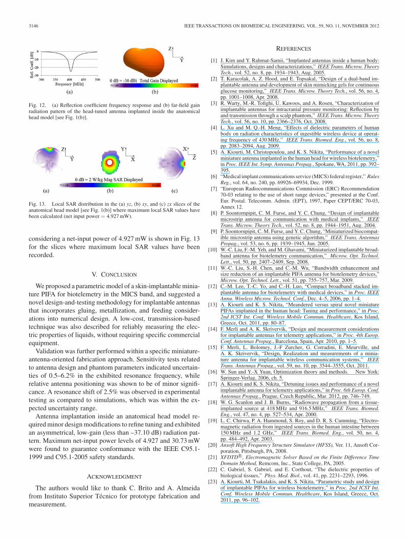
is considered to provide generic results independent of the fab-rication procedure, and fine-tuning is performed (see Table IIunder “head-tuned”) to achieve resonance in the MICS band[see Fig. 12(a)]. Detuning issues for implantable antennas in-side specific anatomical locations have been discussed by theauthors in [5], [17], and [26]. An infinitesimally thin wire anda 50 Ω-voltage source model the 50 Ω-coaxial feed excitingthe antenna. The head-tuned antenna radiates an asymmetricalfar-field gain radiation pattern [see Fig. 12(b)], with a maxi-mum gain of –37.10 dBi exhibited in the (θ, ϕ) = (110◦, 90◦)direction. Low-gain values are attributed to the small PIFAsize and high-tissue loss. Maximum 1-g-averaged (1-g-avg)and 10-g-averaged (10-g-avg) specific absorption rate (SAR)values equal 324.74 and 65.09 W/kg, respectively, for a netinput power of 1 W. The IEEE C95.1-1999 (1-g-avg SAR ≤1.6 W/kg) and C95.1-2005 (10-g-avg SAR ≤ 2 W/kg) safetystandards, thus, limit the maximum allowed net input power to4.927 and 30.73 mW, respectively [27]. Local SAR distribution
3146 IEEE TRANSACTIONS ON BIOMEDICAL ENGINEERING, VOL. 59, NO. 11, NOVEMBER 2012
Fig. 12. (a) Reflection coefficient frequency response and (b) far-field gainradiation pattern of the head-tuned antenna implanted inside the anatomicalhead model [see Fig. 1(b)].
Fig. 13. Local SAR distribution in the (a) yz, (b) xy, and (c) zx slices of theanatomical head model [see Fig. 1(b)] where maximum local SAR values havebeen calculated (net input power = 4.927 mW).
considering a net-input power of 4.927 mW is shown in Fig. 13for the slices where maximum local SAR values have beenrecorded.
V. CONCLUSION
We proposed a parametric model of a skin-implantable minia-ture PIFA for biotelemetry in the MICS band, and suggested anovel design-and-testing methodology for implantable antennasthat incorporates gluing, metallization, and feeding consider-ations into numerical design. A low-cost, transmission-basedtechnique was also described for reliably measuring the elec-tric properties of liquids, without requiring specific commercialequipment.
Validation was further performed within a specific miniature-antenna-oriented fabrication approach. Sensitivity tests relatedto antenna design and phantom parameters indicated uncertain-ties of 0.5–6.2% in the exhibited resonance frequency, whilerelative antenna positioning was shown to be of minor signifi-cance. A resonance shift of 2.5% was observed in experimentaltesting as compared to simulations, which was within the ex-pected uncertainty range.
Antenna implantation inside an anatomical head model re-quired minor design modifications to refine tuning and exhibitedan asymmetrical, low-gain (less than –37.10 dB) radiation pat-tern. Maximum net-input power levels of 4.927 and 30.73 mWwere found to guarantee conformance with the IEEE C95.1-1999 and C95.1-2005 safety standards.
ACKNOWLEDGMENT
The authors would like to thank C. Brito and A. Almeidafrom Instituto Superior Tecnico for prototype fabrication andmeasurement.
REFERENCES
[1] J. Kim and Y. Rahmat-Samii, “Implanted antennas inside a human body:Simulations, designs and characterizations,” IEEE Trans. Microw. TheoryTech., vol. 52, no. 8, pp. 1934–1943, Aug. 2005.
[2] T. Karacolak, A. Z. Hood, and E. Topsakal, “Design of a dual-band im-plantable antenna and development of skin mimicking gels for continuousglucose monitoring,” IEEE Trans. Microw. Theory Tech., vol. 56, no. 4,pp. 1001–1008, Apr. 2008.
[3] R. Warty, M.-R. Tofighi, U. Kawoos, and A. Rosen, “Characterization ofimplantable antennas for intracranial pressure monitoring: Reflection byand transmission through a scalp phantom,” IEEE Trans. Microw. TheoryTech., vol. 56, no. 10, pp. 2366–2376, Oct. 2008.
[4] L. Xu and M. Q.-H. Meng, “Effects of dielectric parameters of humanbody on radiation characteristics of ingestible wireless device at operat-ing frequency of 430 MHz,” IEEE Trans. Biomed. Eng., vol. 56, no. 8,pp. 2083–2094, Aug. 2009.
[5] A. Kiourti, M. Christopoulou, and K. S. Nikita, “Performance of a novelminiature antenna implanted in the human head for wireless biotelemetry,”in Proc. IEEE Int. Symp. Antennas Propag., Spokane, WA, 2011, pp. 392–395.
[6] “Medical implant communications service (MICS) federal register,” RulesReg., vol. 64, no. 240, pp. 69926–69934, Dec. 1999.
[7] “European Radiocommunications Commission (ERC) Recommendation70-03 relating to the use of short range devices,” presented at the Conf.Eur. Postal. Telecomm. Admin. (EPT), 1997, Paper CEPT/ERC 70-03,Annex 12.
[8] P. Soontornpipit, C. M. Furse, and Y. C. Chung, “Design of implantablemicrostrip antenna for communication with medical implants,” IEEETrans. Microw. Theory Tech., vol. 52, no. 8, pp. 1944–1951, Aug. 2004.
[9] P. Soontornpipit, C. M. Furse, and Y. C. Chung, “Miniaturized biocompat-ible microstrip antenna using genetic algorithm,” IEEE Trans. AntennasPropag., vol. 53, no. 6, pp. 1939–1945, Jun. 2005.
[10] W.-C. Liu, F.-M. Yeh, and M. Ghavami, “Miniaturized implantable broad-band antenna for biotelemetry communication,” Microw. Opt. Technol.Lett., vol. 50, pp. 2407–2409, Sep. 2008.
[11] W.-C. Liu, S.-H. Chen, and C.-M. Wu, “Bandwidth enhancement andsize reduction of an implantable PIFA antenna for biotelemetry devices,”Microw. Opt. Technol. Lett., vol. 51, pp. 755–757, Mar. 2009.
[12] C.-M. Lee, T.-C. Yo, and C.-H. Luo, “Compact broadband stacked im-plantable antenna for biotelemetry with medical devices,” in Proc. IEEEAnnu. Wireless Microw. Technol. Conf., Dec. 4–5, 2006, pp. 1–4.
[13] A. Kiourti and K. S. Nikita, “Meandered versus spiral novel miniaturePIFAs implanted in the human head: Tuning and performance,” in Proc.2nd ICST Int. Conf. Wireless Mobile Commun. Healthcare, Kos Island,Greece, Oct. 2011, pp. 80–87.
[14] F. Merli and A. K. Skrivervik, “Design and measurement considerationsfor implantable antennas for telemetry applications,” in Proc. 4th Europ.Conf. Antennas Propag., Barcelona, Spain, Apr. 2010, pp. 1–5.
[15] F. Merli, L. Bolomey, J.-F Zurcher, G. Corradini, E. Meurville, andA. K. Skrivervik, “Design, Realization and measurements of a minia-ture antenna for implantable wireless communication systems,” IEEETrans. Antennas Propag., vol. 59, no. 10, pp. 3544–3555, Oct. 2011.
[16] W. Sun and Y.-X Yuan, Optimization theory and methods. New York:Springer-Verlag, 2006, ch. 5.
[17] A. Kiourti and K. S. Nikita, “Detuning issues and performance of a novelimplantable antenna for telemetry applications,” in Proc. 6th Europ. Conf.Antennas Propag., Prague, Czech Republic, Mar. 2012, pp. 746–749.
[18] W. G. Scanlon and J. B. Burns, “Radiowave propagation from a tissue-implanted source at 418 MHz and 916.5 MHz,” IEEE Trans. Biomed.Eng., vol. 47, no. 4, pp. 527–534, Apr. 2000.
[19] L. C. Chirwa, P. A. Hammond, S. Roy, and D. R. S. Cumming, “Electro-magnetic radiation from ingested sources in the human intestine between150 MHz and 1.2 GHz,” IEEE Trans. Biomed. Eng., vol. 50, no. 4,pp. 484–492, Apr. 2003.
[20] Ansoft High Frequency Structure Simulator (HFSS), Ver. 11, Ansoft Cor-poration, Pittsburgh, PA, 2008.
[21] XFDTD R©, Electromagnetic Solver Based on the Finite Difference TimeDomain Method, Remcom, Inc., State College, PA, 2005.
[22] C. Gabriel, S. Gabriel, and E. Corthout, “The dielectric properties ofbiological tissues,” Phys. Med. Biol., vol. 41, pp. 2231–2293, 1996.
[23] A. Kiourti, M. Tsakalakis, and K. S. Nikita, “Parametric study and designof implantable PIFAs for wireless biotelemetry,” in Proc. 2nd ICST Int.Conf. Wireless Mobile Commun. Healthcare, Kos Island, Greece, Oct.2011, pp. 96–102.

IEEE TRANSACTIONS ON BIOMEDICAL ENGINEERING, VOL. 59, NO. 11, NOVEMBER 2012 3147
[24] D. Popovic, L. McCartney, C. Beasley, M. Lazebnik, M. Okoniewsky,S. C. Hagness, and J. H. Booske, “Precision open-ended coaxial probesfor in vivo and ex vivo dielectric spectroscopy of biological tissues atmicrowave frequencies,” IEEE Trans. Microw. Theory Tech., vol. 53,no. 5, pp. 1713–1722, May 2005.
[25] R. Zajicek, L. Oppl, and J. Vrbaf, “Broadband measurement of complexpermittivity using reflection method and coaxial probes,” Radioengineer-ing, vol. 17, pp. 14–19, Apr. 2008.
[26] A. Kiourti and K. S. Nikita, “Miniature scalp-implantable antennas fortelemetry in the MICS and ISM bands: Design, safety considerations andlink budget analysis,” IEEE Trans. Antennas Propag., vol. 60, no. 8, Aug.2012.
[27] IEEE Standard for Safety Levels with Respect to Human Exposure toRadiofrequency Electromagnetic Fields, 3 kHz to 300 GHz, IEEE StandardC95.1-1999, 2005.