text mining dedicated to technical translation - ACL Anthology
Upload
khangminh22Category
view
3download
0
Joining Tradition with Today
Leigh Router Joinery Jigs
Dedicated Customer Support
1-800-663-8932

CONTENTS and STANDARDSii SUPERJIG-12-18-24 User Guide
Your New Leigh Dovetail Jig Congratulations! You now own a most useful and versatile dovetailing tool. The Leigh Superjig Dovetail Jig will help you cut an infinite variety of joints, and all of its major functions are described in detail in this user guide, plus there’s a slide-out Quick Reference Guide underneath the jig. A very helpful DVD is also included, but the user guide is essential reading.
We recommend that you first assemble and mount the jig, carefully following the instructions in the first section of the user guide. Then read the rest of the guide, following along with the basic functions and principles of operation, before you try to do any actual joinery routing. By all means, cut a few practice joints in scrap boards before you use the jig to rout a precious hardwood work piece! If you have questions not answered in this user guide, please call the Leigh customer support line: 1-800-663-8932or email Leigh: [email protected]. But remember: “If at first you don’t succeed, read the instruc-tions!”
*See Appendix IV – Customer Support
Important! Inches and MillimetersThe Superjig can be ordered in inch or metric versions. They’re identical except for the calibration scales. This Leigh English-language user guide show measurements in both inches and millimeters, with “inches” first, followed by “millimeters” in square brackets.Example: 3⁄4"x 51⁄2"x8" [20x140x200mm]
Do not be concerned if the inch/millimeter equivalents are not exact. Just use the dimensions which apply to your jig.
Where finger assembly scales overlay an illustration, the “inches” scale will be at the top, the “millimeters” scale will be at the bottom. Only the front “active” half of the scales are illustrated. For clarity, setting positions are indicated with a red line in the user guide only. On the jig, the lines are black.
1
2

iiiCONTENTS and STANDARDS SUPERJIG-12-18-24 User Guide
Contents and Standards ........................................................................................... iiiChapter 1 – Jig Assembly, Mounting, and Using The Clamps .................................. 1Chapter 2 – Adjusting the Finger Assembly ............................................................. 7Chapter 3 – The Leigh e-Bush and Optional Guidebushes ....................................... 9Chapter 4 – Basic Jig Functions and Scale Modes ................................................... 11Chapter 5 – Using Your Jig Safely ............................................................................ 13Chapter 6 – Wood Preparation ................................................................................ 15Chapter 7 – Router Preparation ............................................................................... 17Chapter 8 – Through Dovetail Procedures .............................................................. 19Chapter 9 – Variably Spaced Half-Blind Dovetail Procedures ................................ 29Chapter 10 – Single Pass Half-Blind Dovetails ........................................................ 37Chapter 11 – Rabbeted Half-Blind Dovetails .......................................................... 45Chapter 12 – Asymmetric Dovetails ....................................................................... 47Chapter 13 – Sliding Dovetails ................................................................................. 51Chapter 14 – Box Joints ............................................................................................ 57Chapter 15 – Hints and Tips ..................................................................................... 63Appendix I – Attaching the Leigh e-Bush to the Router ........................................ 67Appendix II – Bit Selection ....................................................................................... 69Appendix III – Jig Parts ............................................................................................. 75Appendix IV – Customer Support ............................................................................ 79

CONTENTS and STANDARDSiv SUPERJIG-12-18-24 User Guide
1
2
1
Glossary of Symbols To help you understand the instructions and illustrations in this user guide, we have used a number of international symbols, plus a few special ones of our own. They are all explained below. You needn’t worry about memorizing these symbols now, because they are repeated quite frequently throughout the user guide, and you will soon get used to them.
The Leigh jig’s guidefinger assembly can be in any one of four joint modes, depending on what type of joint and which part of the joint you are routing. Each finger assembly scale has it’s own mode icon , identifying that joint part. You will also find the joint mode icon in the top left corner of most illustrations , indicating which finger assembly mode to use.
Sometimes a joint mode icon will be used to identify a board .
These are the four joint mode icons:
TD Tails (tails for through dovetail joints)
TD Pins (pins for through dovetail joints)
HB Tails (tails for half-blind dovetail joints)
HB Pins (pins for half-blind dovetail joints)
3

vCONTENTS and STANDARDS SUPERJIG-12-18-24 User Guide
Which Way Round Should the Board Go? As virtually all dovetail joinery is used to make boxes, drawers and chests etc., we devised these simple (and hopefully intuitive) icons to indicate which side of a board faces inwards or outwards on the finished “box”, and which side of the board faces outward (toward you, the operator), when it is clamped in the jig.
The following symbols indicate:
e This edge against sidestop
f This edge against sidestop
Sawcut allowance
Caution: use special care for this operation
Numbered References in text
This icon o indicates the “outside” of a board. All through dovetail pin boards are mounted in the jig with this “outside” face away from the jig (toward you, the operator).
This icon i indicates the “inside” of a board. All half-blind pin and half-blind tail boards, and through dovetail tail boards, are mounted in the jig with the “inside” face away from the jig toward you, the operator.
This icon j indicates boards that are mounted both ways e.g. sliding dovetails and box joints.
Dotted line icons indicate the
“other” side of the board in the illustrations.
Centerline of board or layout
Equals
Does not equal
Approximately

CONTENTS and STANDARDSvi SUPERJIG-12-18-24 User Guide
VRS ModelsItem VRS12 Vacuum & Router Support for the Super 12 Dovetail JigItem VRS18 Vacuum & Router Support for the Super 18 Dovetail Jig Item VRS24 Vacuum & Router Support for the Super 24 Dovetail Jig
Dust-Free Routing!The revolutionary Leigh VRS Vacuum & Router Support* provides almost 100% dust and chip collection as well as amazing full width router support. The VRS is a must-have for all Leigh dovetail jig owners. *US patent: USPN 7,507,060 B2 UK patent: GB2446909
Here’s How It WorksThe VRS is mounted on brackets on the front of the jig and the router is sup-ported by the finger assembly and the full width beam of the VRS. The vacuum chute rides under the router support beam. Control arms, attached to the vacuum chute, surround the router. These arms are adjustable to accommodate any router base. As the router moves across the joint, the vacuum chute glides effortlessly from side to side on nylon rollers. The chute is always in perfect position to catch the dust and chips thrown out by the router bit. Chips and sawdust are drawn into the vacuum chute and down through the vacuum hose. Each VRS comes complete with two adaptors to fit all popular vacuum hose sizes and the VRS can be used with a small shop vac or a large built in system. The VRS is easily attached without jig modification. Each VRS comes complete with all mounting hardware needed for any Leigh 24" D-Series jig, all Super Jigs or the earlier model Leigh D1600.
VRS Vacuum & Router Support Features• Full width router support• Easy on Easy Off. Powerful rare earth
magnets secure router support beam• Park the router when not in use• Vacuum box glides effortlessly under
router support beam• Control arms position vacuum box
• Control arms adjust to any router• No hoses to obstruct view• No jig modifications necessary• Models for all Leigh jigs• All mounting hardware included• Adapt to any hose size
The dust chute rides beneath the router support beam. Control arms ensure accurate positioning of the chute and the size and shape of the chute ensures total waste collection regardless of bit size or joint type being routed.
The VRS will work with almost any shop vac or large vac system. Two adaptors are included with every VRS to handle hose sizes from 1" to 2-1/2".
The VRS is a full width router support. When the work piece has been routed on one side of the jig, the router can be effortlessly moved to the other side of the jig and parked while the work piece is being changed. There is no need to remove the router from the jig.
Because the vacuum box is always in perfect position relative to the router bit, the dust and chips com-ing off of the router bit are auto-matically drawn into the chute and vacuum hose.
Accessory KitsItem AC12 VRS12 and 1607-8 Bit Set for the Super 12 Dovetail JigItem AC18 VRS18 and 1607-8 Bit Set for the Super 18 Dovetail JigItem AC24 VRS24 and 1607-8 Bit Set for the Super 24 Dovetail Jig
Standard Equipment• Router Support Beam• Vacuum chute• Hose adaptors – small and large• Support rails• Screws and washers• Hex key
Leigh VRSVacuum & Router Support

10
1 2 3 4
65 7 8
9
Jig Assembly, Mounting,and Using the Clamps
SUPERJIG - CHAPTER 1
Make Sure You Have All the Parts.
Before you start to assemble your Leigh SUPERJIG, check to make sure you have received all the required parts.
The small carton you removed from the end of the main carton contains:
1. 2 support brackets2. 4 cam-action speed clamps 4 cam clamp pivot nuts 3. 1 e7-Bush & Nut with Pin Wrench 2 each, front and rear Side Stops 1 Spacer 4. 2 support knobs5. 4 clamp springs 4 clamp T-bolts 4 flat washers 4 T-bolt nuts 4 Jig Hold-down Wood Screws No.10 x 1"6. 2 scale thumbscrews c/w nylon washers7. 2 Dovetail bits, 1 straight bit, 1 Collet Reducer8. Square-head guidefinger screwdriver Also included are any other small optional items you may have ordered with your new jig. Check the packing slip for this information.
The main carton contains: 9. 1 main jig body 1 Leigh jig User Guide Warranty/Registration Card DVD instructional video (English only)
The large inner box contains:10. 1 finger assembly on a bar, complete with scales Super12, with 13 guidefingers Super18, with 16 guidefingers Super24, with 19 guidefingers 2 lengths bridge material – see Chapter 9 1 crosscut fence (same as bridge) – see Chapter 13 2 clamp bars c/w end plugs 1 Nylon Stop Rod – see Chapter 10 1 Quick Reference pull-out card
If any items are missing from your jig, contact your supplier or Leigh Industries immediately.
Important NoteMount your jig securely, assemble it completely, and make sure you have read and understood the Safety section of this user guide before using the jig.
1

JIG ASSEMBLY, MOUNTING, AND USING THE CLAMPS2 Chapter 1 SuperJig-12-18-24 User Guide
1-1 Install Side Stops Insert two clamp T-bolts through the rear jig body holes and place a “stepped” rear side stop over each bolt , using the rear part of the double-hole . Make sure the bolt's “T” is between the extrusion ribs ➃. Don’t forget the steel washer ➄ and use a ½"[13mm] wrench to tighten the nuts.
3
1
4
4
1
2
5
1-2 Insert the two front clamp T-bolts through the jig body holes. Make sure the bolt's “T” is between the extrusion ribs. Place a front side stop and steel washer over each bolt but only finger-tighten the front nuts; you will need to index these to the rear stops later.
1-3 Prepare a flat ¾"[20mm] mounting board (plywood or MDF), at least 5"[125mm] wide. Length : 26" for Super12, 32" for Super18, 40" for Super24 [660, 830 or 1000mm respectively]. Clamp it to the front of your bench. Center the jig on the board, front face slightly overhanging the board edge . Mark the four hold down screw posi-tions. Drill small pilot holes at a slight angle .
2
3
5"[125mm]+
1
1-4 Quick Reference Pull-Out Decide which end of the jig you wish to access the “Quick Reference” instruction pull-out and place the jig over the pull-out . Using the screws provided; screw the jig to the board. Make sure that the pull-out slides freely.
1
1-5 Place four springs and two clamp bars on the T-bolts. Make sure the clamp bars move freely on the T-bolts.
1
1
1-6 Screw a clamp lever assembly onto each T-bolt.

3JIG ASSEMBLY, MOUNTING, & USING THE CLAMPS Chapter 1SuperJig-12-18-24 User Guide
1-7 Now you need two boards about ¾" x 6" x 8" long [20 x 150 x 200mm]. Both must have perfectly square ends to accu-rately index the front and rear side stops.
Check for squareness: stand both pieces vertically on a flat surface. Make sure side edges are flush at bottom and top .
Turn one piece around on its end . If side edges are flush top to bot-tom , the boards are square. If not, ➃; cut two that are.
90˚
90˚
90˚
90˚
1
4
2
3
1-8 Align Front Side Stops Clamp one square ended board in the front, not touching the left side stop and with the top edge above the top surface of the jig body . Place the other square board in the rear clamp, tight against the left rear side stop , with its front edge touching flush across the rear of the vertical board . Tighten the rear clamp.Note: Do not overtighten the right hand clamps during this step.
390˚
90˚ 1
2
1-9 Now loosen the front clamp and position the front board so its top end edge is perfectly flush and level with the top face of the horizontal board and, both boards left edges are also perfectly flush . Tighten the clamp.
1
2
1-10 Now push the front left side stop inwards and flush against the vertical board and firmly tighten the clamp bolt nut.Repeat operations 1-8 thru 1-10 at the right side of the jig. The front and rear side stops are now indexed to provide accurate board alignment in all routing procedures. You may now remove the boards.
1
2
1-11 Insert the right and left support brackets. Attach the knobs, raise them to full height and tighten the knobs.Note: For clarity, the set lines on support brackets are shown in red in this user guide. The actual bracket lines are black.
1
1-12 Make up a 3⁄4"x 6"[20 x 150mm] finger support board as shown. Lengths: 11"[280mm] for Super12, 17"[430mm] for Super18, and 23"[600mm] for Super24. This board will support the guidefinger assembly in all front-clamping vertical board modes. Clamp it in the rear of the jig.

JIG ASSEMBLY, MOUNTING, AND USING THE CLAMPS4 Chapter 1 SuperJig-12-18-24 User Guide
1-13 Before using the jig, the scales must be set into position on the finger assembly. Install the two thumbscrews a few turns into the scales . Loosen the scale lock screw at each end by one turn only.
1
2
1
1
1-15 Pull up on the finger bar while pushing down on the scale to ensure the bar is touching the two registration pads inside the scale. Maintain pressure and tighten the scale lock-screw ➃. Repeat at the other end. To maintain correct finger assembly alignment, follow this procedure whenever you remove the scales from the finger assembly.
3
4
2
1
1-16 With the finger assembly in dTD Pins mode , move the outer end guidefingers to touch the scale block and lock in posi-tion . Note: the outer end guidefingers are used for router support only. When guidefingers are loosened, the finger assembly should easily slide on the support brackets. If not, apply a little candle wax to the mating surfaces.
1
2
1-17 Finally, slip the Spacer on the outside of the left rear side stop , the nylon stop rod through its storage hole in the left end and the pin wrench in its slot in the right hand end housing .
1
2
3
1-18 With Superjig assembled and mounted, you have some items left over:
1-14 Slide the finger assembly onto the support brackets, in the dTD Pin mode and set on the 1⁄2"[12,7mm] setting. First, tighten both thumbscrews .Do not lower the assembly onto the finger support board.
1 Leigh jig user guide
1 DVD instruction video (English only)
1 Leigh e7-Bush and nut
2 Dovetail bits
1 Straight bit
1 Collet Reducer
1 square-head screwdriver
3 bridge-piece/crosscut extrusions
I M P O R TA N T

5JIG ASSEMBLY, MOUNTING, & USING THE CLAMPS Chapter 1SuperJig-12-18-24 User Guide
1-19 The Jig Clamps Use a piece of flat, even-thickness wood to familiarize yourself with the jig cam clamps. You will operate the cam-action speed clamps every time you use the jig, so get used to the feel of the clamps first. Do not force the cam-action speed-clamp. It has great leverage, and excessive force may damage the workpiece or the jig.
1-20 A smooth, firm action is enough to engage the clamp.Rule of thumb: If you can't throw the lever by pressing the end of it firmly with your thumb, reduce the tension. Firm thumb pressure is about right. A few minutes of trial and error will help you feel the right clamp tension.
1-21 For all but the wider workpieces, you need only operate the clamp on the workpiece end of the jig to release the board . For narrower boards, the clamp at the free end should be just tight enough to bow the clamp bar about 1⁄16"[2mm] .
1
2
3
1-22 When engaged, the front clamp levers should normally point down and the rear levers should point away from the operator or up to 90˚ either side as required to obtain the optimum clamping pressure.
1
2
2
1
1-23 To gain height for a more comfortable working position or for routing longer boards, mount the jig to a box that can be bolted securely to a bench.See also 15-13. ■

JIG ASSEMBLY, MOUNTING, AND USING THE CLAMPS6 Chapter 1 SuperJig-12-18-24 User Guide

Adjusting theFinger Assembly
SUPERJIG - CHAPTER 2
7
2-1 Practice with the finger assembly height adjustment. Loosen the support bracket knobs and hold them firmly. Raise and lower the assembly evenly, keeping it level , and tighten the knobs to lock it at various heights. Do not raise or lower only one end of the finger assembly.
1
1
2-2 To practice adjusting the guidefingers, put a board in the front clamp. Always raise the finger assembly slightly, approximately 1⁄16"[2mm] above the spacer board and/or workpiece . This is essential to allow the guidefingers to move freely on the guidefinger bar and ensures that the fingers will be level and flush when locked up. Move the guidefingers by pushing on the middle to slide them along the guidefinger bar.
1
2-3 Loosen about half the guidefingers and practice unlock-ing, moving, positioning and re-locking them. Always press on the center of the guidefinger when tightening the screws. This ensures that the small pads on the inside of the finger contact the face of the finger bar and keeps all the fingers level.
1
2
2-4 Do not over-tighten the guidefinger lock screws. The Leigh screwdriver provided will give ample torque for easy lock-up with-out strain.Hint: Fingertip tighten a loose screw until the slightest resistance is felt. Do not tighten the screw more than half a turn (180˚) from the first contact.

ADJUSTING THE FINGER ASSEMBLY8 Chapter 2 SuperJig-12-18-24 User Guide
2-6 You can adjust the guidefingers by eye, or by measurement to suit a set of plans. ■
2-5 Always tighten unused guidefingers before routing, as router vibration may cause loose screws and finger lock parts to fall out and be lost.
20"
3/4"thick
1 1/4" centres
3/4"thick
1/4"
1
12
34
65
78
910
11 12 13 1415 16 17 18 19
20 21 2 23 24 2526
2728
31
3334
32
31
30
29
23
45
67
89
10
11
12
13

SUPERJIG - CHAPTER 3
The Leigh e-Bush and Optional Guidebushes
The guidebush is the vital link between router and jig. All joints created on a Superjig are routed with the unique e7* elliptical guidebush, a Leigh innovation that provides precise joint fit adjustment for box joints and sliding dovetails. If your router doesn’t accept the e7-Bush, you can use an alternative guidebush with some limitations.*Supplied with each Superjig. U.S. Patent No. 8,256,475. UK Patent No. GB2443974. Patent Pending in Canada.
9
3-1 The Leigh e7-Bush is used to rout through, half-blind, single pass half-blind and sliding dovetails on a Superjig. The elliptical design provides precise joint fit adjustment for box joints and sliding dovetails. A round ~7/16"[11,1mm] guidebush (min. barrel length 1/4"[6,35mm]), can be used to rout through, half-blind, and sliding dovetails on the Superjig, but the e7-Bush is superior.
These images were copied from D4R Pro UG Fig’s 8-42 and 3-2
1 2
7/16" [~11,1mm]~
[6,35mm]1/4"min.
3-2 The Leigh e7-Bush that comes with your Superjig is a unique template guidebush that is adjustable in size. Unlike regular circular template guidebushes , the e7-Bush is slightly elliptical in cross section . This simple innovation effectively changes the guidebush “active diameter size” when it’s rotated, and provides benefits not possible with a standard round guidebush.
1
2
3-3 The e7-Bush (~ 7/16") fits the router base or a guide bush adaptor in the base (see Appendix I). The ellipse/oval shape has a major axis ~ 7/16"[11,1mm], and minor axis ~ 7/16"[11,1mm]
less .020"[,5mm]. Turning the e-Bush 90 degrees in the router base changes the active diameter by .020"[,5mm] providing minute adjustment and recordable settings for perfectly fitting box joints.
1
2 1
2
~7⁄16"[~11mm] ~7⁄16"[~11mm] less .020"[,5mm]
3-4 Here’s how it works. In normal use on a dovetail jig, the operator does not rotate the router more than a few degrees either way . In fact, because of potential bit-to-bush eccentricity prob-lems it is advisable to minimize router rotation on jigs .
1 2

THE LEIGH e-BUSH AND OPTIONAL GUIDEBUSHES10 Chapter 3 SuperJig-12-18-24 User Guide
1
3-5 Establish the orientation in which you normally hold and operate the router on the jig. Now, up-end the router in the same orientation. Make a small scratch line or permanent ink mark on the router base or e-Bush adaptor at the 12 o’clock position .
3-6 Fit the e7-Bush to the router and align No.10 to the scratch mark. The No.10 setting is used for all through and variably spaced half-blind dovetails on Superjigs. Settings for single pass half-blinds, box joints and sliding dovetails are described in applicable chapters. Be sure to retighten the e-Bush nut after each adjustment.
3-7 The bit goes through the guidebush and fits in the router collet or chuck.
3-8 The projecting part of the guidebush runs along the side edge of the guide finger. The rotating bit cuts the wood only, and touches neither the guidebush nor the guide surface. ■

Basic Jig Functionsand Scale Modes
SUPERJIG - CHAPTER 4
Here are the basics for understanding the different Superjig dovetail modes and settings.
2. TD PINS
3. HB TAILS
4. HB PINS
1. TD TAILS
THE FOUR SCALE MODESThe Finger Assembly attaches to the support brackets in four different modes to match the type of joint you are cutting.
This line is for the finger assembly scales. The line is illustrated in red for clarity in this user guide, but is black on the jig.
Note: Inch scales are shown here. Millimeter scales have similar layouts.
The inactive scale is always on the rear of each scale assembly and is upside-down.
The active scale is always on the front of each scale assembly.
Scales are color coded.• Green: Half-Blind Dovetails.• Silver: Through Dovetails.
Each scale has its own mode icon (a drawing of the joint part made in that mode).
Reading scales from directly a b o v e h e l p s sight the lines accurately.
The specific settings for each scale are fully described in the appropri-ate chapters.
11

BASIC JIG FUNCTIONS AND SCALE MODES12 Chapter 4 SuperJig-12-18-24 User Guide
4-1 The two clamp bars hold workpieces horizontally or vertically. The side stops align the boards in the correct posi-tion each time.
1
12
2
2
2
4-2 The guidefinger assembly slides in the support brackets above the workpiece. The finger assembly is adjusted in or out using calibrated scales on each end to suit different thicknesses of vertical boards.
12
2
4-3 The finger assembly is raised or lowered using the support brackets to suit different thicknesses of horizontal boards. ■

Using Your Jig Safely
SUPERJIG - CHAPTER 5
Safety is not optional.
Read and follow the recommendations in this chapter.
5-4 Always disconnect the power source from the router when fitting bits or guidebushes, or making adjustments.Before connecting the router to the power source, make sure the bit and collet revolve freely in all the areas you plan to rout, and the bit does not touch the guidebush or jig.
5-1 Read the user guide that came with your router. It is essential to understand the router manufacturer’s instructions completely. Always operate variable speed routers at the fastest possible speed.
5-2 Always wear approved safety glasses.Always wear hearing protection.Protect yourself from harmful dust with a face mask.For complete comfort and convenience, get yourself a Leigh VRS (Vacuum & Router Support) to match your jig model.
5-3
Never drink alcohol or take medications that may cause drowsiness when you will be operating a router.
13
USING YOUR JIG SAFELY14 Chapter 5 SuperJig-12-18-24 User Guide
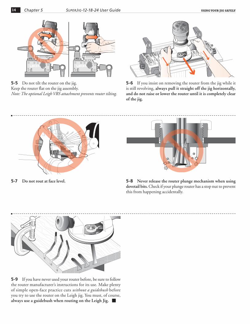
5-5 Do not tilt the router on the jig.Keep the router flat on the jig assembly.Note: The optional Leigh VRS attachment prevents router tilting.
5-6 If you insist on removing the router from the jig while it is still revolving, always pull it straight off the jig horizontally, and do not raise or lower the router until it is completely clear of the jig.
1
5-7 Do not rout at face level. 5-8 Never release the router plunge mechanism when using dovetail bits. Check if your plunge router has a stop nut to prevent this from happening accidentally.
5-9 If you have never used your router before, be sure to follow the router manufacturer’s instructions for its use. Make plenty of simple open-face practice cuts without a guidebush before you try to use the router on the Leigh jig. You must, of course, always use a guidebush when routing on the Leigh Jig. ■
Wood Preparation
SUPERJIG - CHAPTER 6
"Garbage In - Garbage Out"...
This adage of the computer age stands equally true for dovetail jigs.
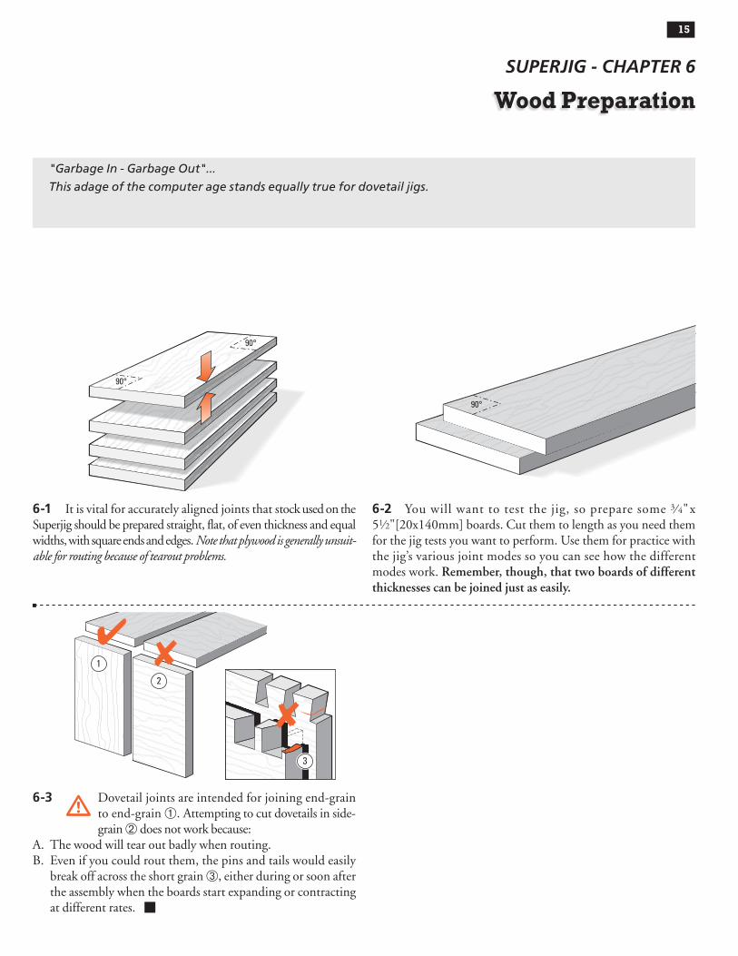
6-1 It is vital for accurately aligned joints that stock used on the Superjig should be prepared straight, flat, of even thickness and equal widths, with square ends and edges. Note that plywood is generally unsuit-able for routing because of tearout problems.
90°
90°
6-2 You will want to test the jig, so prepare some 3⁄ 4" x 51⁄2"[20x140mm] boards. Cut them to length as you need them for the jig tests you want to perform. Use them for practice with the jig’s various joint modes so you can see how the different modes work. Remember, though, that two boards of different thicknesses can be joined just as easily.
90°
6-3 Dovetail joints are intended for joining end-grain to end-grain . Attempting to cut dovetails in side-grain does not work because:
A. The wood will tear out badly when routing.B. Even if you could rout them, the pins and tails would easily
break off across the short grain , either during or soon after the assembly when the boards start expanding or contracting at different rates. ■
1
2
3
15

WOOD PREPARATION16 Chapter 6 SuperJig-12-18-24 User Guide
Router Preparation
SUPERJIG - CHAPTER 7
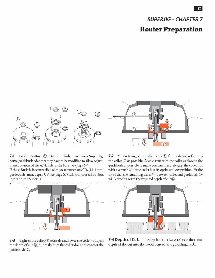
7-1 Fit the e7-Bush . One is included with your Super Jig. Some guidebush adaptors may have to be modified to allow adjust-ment rotation of the e7-Bush in the base. See page 67.If the e-Bush is incompatible with your router, any 7/16[11,1mm] guidebush (min. depth 1/4" see page 67) will work for all but box joints on the Superjig.
1
11
7-2 When fitting a bit to the router , fit the shank as far into the collet as possible. Always rout with the collet as close to the guidebush as possible. Usually you can't securely grip the collet nut with a wrench if the collet is at its optimum low position. Fit the bit so that the remaining travel ➃ between collet and guidebush ➄ will let the bit reach the required depth of cut .
1
3 2
54
46
7-3 Tighten the collet securely and lower the collet to adjust the depth of cut , but make sure the collet does not contact the guidebush ➄.
2
5
6
7-4 Depth of Cut: The depth of cut always refers to the actual depth of the cut into the wood beneath the guidefingers .
1
17

ROUTER PREPARATION18 Chapter 7 SuperJig-12-18-24 User Guide
7-5 Depth of cut is not the distance the bit projects from the router base. This is bit projection . This user guide generally refers to depth of cut. Bit projection is always .500"[12,7mm] more than depth of cut.
2
7-6 Ideally, the router collet (and bit) should be concentric (cen-tered) to the guidebush as in figure 7-5. Regrettably, this is often not the case; the bit can be off center (eccentric to) the guidebush . The illustration shows the problem highly exaggerated. The good news: bit to bush alignment doesn’t affect joint fit or flushness; both are “adjusted out” in normal jig setup.
1
7-7 Concentricity problems can only arise if two routers are used for through dovetails, (one for pins; one for tails). Routers with different bit to guidebush offsets (misalignment shown highly exaggerated)…
22
7-8 …will cause pin to tailboard misalignment (again, shown highly exaggerated). Fortunately, some newer routers have sub-bases that can adjust for concentricity. If you don’t have this type, it might pay to stick to a single router for through dovetails. ■
3
3

Through DovetailProcedures
SUPERJIG - CHAPTER 8
In these instructions for using the Leigh Superjig dovetail Jig, we recommend using certain bits and board sizes just because they are easy to work with. When you have cut some practice joints and gained confidence in your ability to get the results you want, feel free to use the bit selection charts in Appendix II to plan whatever dovetail routing you need for your projects.
Start in
Through Dovetail Tails (TD TAILS) mode
ROTATE the finger assembly toward you 180°
Start with the Finger Assembly in the D TD TAIL mode and follow these steps on your jig. Grasping the simple basic concept of operation will now greatly assist you in understanding the instructions. Note that the active guide surface (against which the guidebush runs) is indicated in red in these illustrations.
MODE ICONSIllustrations in this user guide include the correct mode icon for the cur-rent instruction. The icons are also used in the instruction text.
Concept of Jig Operation – THROUGH DOVETAILS
Inches Millimeters
ActiveGuide Surfaces
TD PINS
TD TAILS
1
2
Now the Finger Assembly is in
Through Dovetail Pins (TD PINS) mode3
Inches Millimeters
ActiveGuide Surfaces
19

THROUGH DOVETAIL PROCEDURES20 Chapter 8 SuperJig-12-18-24 User Guide
8-1 Through Dovetail Terminology:
��
�
���
8-2 Let’s look at how to make a simple square box. When you assemble the finished pieces with the faces properly oriented, then any one of the pin ends will fit any one of the tail ends. In fact, the box can be put together in six different ways.
8-3 For this trial you need five identical boards 3⁄ 4"x 5-1⁄2"[20x140mm] x about 8"[200mm] long. Mark inside faces for two tailboards and outside faces for three pinboards (one pinboard is a spare). Use the e7-Bush, the No. 80-8 1⁄2"[12,7mm]x 8° dovetail bit and 140-8 5⁄16 "[7,9mm] straight bit (all included with Superjig). Note: 13 ⁄16 "[20mm] is maximum through pin board thickness.
8-4 Fit the E-7 guidebush to the router. Align the No. 10 mark with the base mark . No guidebush adjustment is required with through dovetails. If you have a router that is incompatible with the e-Bush, you can use a standard 7⁄16"[11,1mm] guidebush (min. depth 1⁄4" see page 67) for through dovetails.Then fit the supplied 80-8 dovetail bit to the router.
1
8-5 Clamp the finger support board in the rear clamp. 8-6 Place the finger assembly on the support brackets in the dTD PINS mode, flat on the spacer board, and with the scale set on the 1⁄2"[12,7mm] setting for now. Don’t worry about the scale’s specific meaning now. Each scale’s use will be fully explained in the appropriate section.
Pins Pin sockets Half-pins
Half-pin sockets Tails Tail sockets
The pins fit in the pin sockets. Joints should almost always end each side with half-pins.

21THROUGH DOVETAIL PROCEDURES Chapter 8SuperJig-12-18-24 User Guide
8-7 Clamp a tail board against the left front side stop, top edge touching flush under the guidefingers, inside face i away from the jig body. Although you will cut tails first, adjust the guidefinger layout in dTD PINS mode. The adjustment screws are on top in this mode, and it's easier to visualize the finished joint pattern.
8-8 Loosen the support bracket knobs and raise the finger assembly about 1⁄16"[2mm] above the boards, then re-tighten the knobs. This will allow easy and accurate guidefinger adjust-ment.
1
8-9 This joint layout is just a suggestion for this trial. It has a typical, traditional symmetrical pin layout, with half-pins at each edge. The Superjig however, allows for infinite dovetail spacing. Also, boards of different thicknesses can be joined to each other as shown in this illustration. Before attempting an asymmetrical joint layout, see chapter 12.
8-10 Ignoring the extreme outer guidefinger next to the scale (it just supports the router), loosen the next five guidefingers and slide them over the top of the workpiece.
8-11 Lock the left-most guidefinger with its center-line about 1⁄8"[3mm] in from the left edge of the board to form a half-pin.
1
8-12 Leave three guidefingers over the board. Lock the right-most guidefinger with its center-line about 1⁄8"[3mm] in from the right edge of the board to form the other half-pin. Judge this distance by eye: it need not be exact. The sockets and pins will align automatically.
2

THROUGH DOVETAIL PROCEDURES22 Chapter 8 SuperJig-12-18-24 User Guide
8-13 Space and lock the three remaining guidefingers as shown. Again, judge it by eye. If it looks right on the jig, the finished joint will look right.
8-15 Rotate the finger assembly to DTD TAILS mode, and set it to the "ALL" position on the scale. Lower the finger assembly onto the spacer board. All TD tails are routed at this "ALL" setting. (This setting allows the dovetail bit to pass completely through all tail boards.)
8-16 Place the end of a pin board horizontally flush under the guidefingers and mark a thin pencil line partly across the tail board.
REMEMBER SAFETY!
8-17 Place the router on the finger assembly and adjust the router until the dovetail bit tip is level with the center of the pencil line. Note: This means the pin socket will be half a thin pencil line deeper than the thickness of the pin board, leaving minimal clean-up after assembly.Check to make sure the bit rotates freely.
8-18 Plug in the router and rout out the half-pin and pin sockets. Use only light side pressure on the guide fingers. Make sure to run the guidebush along both sides of the finger opening. Take care not to rout unwanted sockets where there are gaps between pairs of fingers . Rout only between the rounded guidefinger tips. See Hints and Tips Chapter 15.
1
8-14 Tighten any other loose guidefingers.
23THROUGH DOVETAIL PROCEDURES Chapter 8SuperJig-12-18-24 User Guide
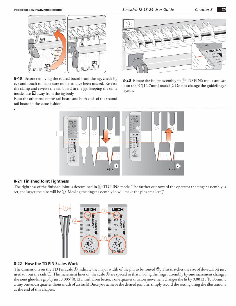
8-19 Before removing the routed board from the jig, check by eye and touch to make sure no parts have been missed. Release the clamp and reverse the tail board in the jig, keeping the same inside face i away from the jig body.Rout the other end of this tail board and both ends of the second tail board in the same fashion.
8-20 Rotate the finger assembly to dTD PINS mode and set it on the 1⁄2"[12,7mm] mark . Do not change the guidefinger layout.
8-21 Finished Joint TightnessThe tightness of the finished joint is determined in dTD PINS mode. The farther out toward the operator the finger assembly is set, the larger the pins will be . Moving the finger assembly in will make the pins smaller .
1 2
8-22 How the TD PIN Scales WorkThe dimensions on the TD Pin scale indicate the major width of the pin to be routed . This matches the size of dovetail bit just used to rout the tails . The increment lines on the scale are spaced so that moving the finger assembly by one increment changes the joint glue-line gap by just 0.005"[0,125mm]. Even better, a one quarter division movement changes the fit by 0.00125"[0,03mm], a tiny one and a quarter thousandth of an inch! Once you achieve the desired joint fit, simply record the setting using the illustrations at the end of this chapter.
2
1
4
3

THROUGH DOVETAIL PROCEDURES24 Chapter 8 SuperJig-12-18-24 User Guide
1
2
8-23 Clamp a test pin board against the left hand side stop, outside face o away from the jig, with the top end flush under the guides .Place the side edge of one of the finished tail boards horizontally flush under the guidefingers and mark a thin pencil line part way across the pin board .
8-24 Unplug the router and remove the dovetail bit. Mount the included No. 140-8 straight bit to the router.
8-25 Place the router on the finger assembly and adjust the router until the bit tip is level with the center of the pencil line. Check to make sure the bit rotates freely.
8-26 Rout out the waste between the pins. Check to make sure no parts have been missed. See Chapter 15 "Hints and Tips" on how to minimize tearout.
8-27 Remove the test pin board from the jig and test it for fit in one of the tail boards.Make sure the outside faces outward on both pieces. A firm push fit is perfect, perhaps a tap with the heel of your hand. Having to use a mallet means the joint is too tight to take glue.
90o
8-28 If it is too tight, move the finger assembly in (away from you) by one division on the scale. If it is only a little tight, adjust the scale by only half a division. Replace the same pin board back in the jig, carefully aligned against the same side stop. Rout off the sides of the pins and test it again for fit. Repeat as necessary to get a good fit.

25THROUGH DOVETAIL PROCEDURES Chapter 8SuperJig-12-18-24 User Guide
90o
2
1
8-29 If the joint is loose, pull the pin board so that the angled sides of the pins and sockets jam tight together . The gap at the bottom of the pins is the amount you will have to move the finger assembly out (toward you). Reset the finger assembly and test again on the other end of this board.
8-30 Once the correct fit is achieved, mark the final dTD PINS scale setting on the pull-out or on one of the scale prints at the end of this chapter. Very slight variations to the scale setting may be necessary with different wood species or hardness. You can also note this on the Quick Reference pull-out card.
8-31 Rout all four ends of the pin boards, keeping the outside face o outwards. (With luck you may not have used the fifth board.)
8-32 Assemble the box, making sure the tail boards face the proper way, i.e. tail boards inside face in i; pin boards outside face out o. Provided you haven't already routed out the drawer bottom grooves , it doesn't matter which edge of any of the boards are at the top or bottom, the box will still fit together i.e. pin board “A” can be up either way.
X
A
A
X
Y
Y 1
8-33 The box should be square and in plane. If it is not in plane (i.e., the side edges of each board are not in line), then either the ends of the boards are not square, the board widths are not exactly equal, or there is a concentricity problem (see 7-2 to 7-7).
8-34 To form angled dovetails, refer to the Technical bulletin “How to Rout Angled Through Dovetails on your Leigh Jig”. You can download a printable file of the bulletin from our website: www.leighjigs.com/support.php. ■

THROUGH DOVETAIL PROCEDURES26 Chapter 8 SuperJig-12-18-24 User Guide
8-QR1 Through dovetails are laid out in dTD PINS mode with the finger assembly slightly raised above the spacer board and the pin board. The outside face o of the TD pins is away from the jig body.
8-QR2 TD tail boards are clamped vertically in the jig. The inside face i of the TD tails is away from the jig body. The fin-ger assembly is in DTD TAILS mode, set on the “ALL” setting. There is only one setting in this mode.
1
8-QR3 The finger assembly is in dTD PINS mode, with the scale set to a recorded setting (see detailed fit instructions, 8-24 to 8-30). TD pins are cut with a straight bit; the only time a straight bit is used in dovetailing.This is the only one of the four main modes that puts the outside face of the board away from the jig body.
8-QR4 Through dovetail tails are always routed with an 8° dovetail bit to match the 8° guide finger. All through dovetail routing on the Superjig is done with the Leigh e7-Bush, or any ~7⁄16" [11,1mm] diameter bush (min. barrel length 1/4"[6,35mm]). See page 68 for more on routers and guide bushings.
[6,35mm]1/4"
7/16" [11,1mm]~
8-QR5Here is a quick reference selection chart for through dovetail bits and guidebushes. Please study the bit and guidebush selection appendices for a full explanation. Note: 13⁄16"[20mm] is the maximum through pin board thickness. ■Thickness of
Tail BoardThickness of
Pin BoardDovetail
BitStraight
BitGuidebushDiameter
up to 13/16"[21] 1/2" - 13/16" [12-20] No.80-8
No.140-8
e7-Bush or~ 7/16" [11,1]
diameter
bush
up to 13/16"[21] 3/8" - 5/8" [10-16] No.75-8
up to 13/16"[21] 1/4" - 1/2" [6-13] No.70-8
up to 13/16"[21] up to 3/8" [10] No.60-8
up to 13/16"[21] up to 1/4" [6] No.50-8Numbers in brackets are millimeters
QUICK REFERENCE REMINDERS

27THROUGH DOVETAIL PROCEDURES Chapter 8SuperJig-12-18-24 User Guide
SAMPLE
INC
HES
MET
RIC
Project Settings

THROUGH DOVETAIL PROCEDURES28 Chapter 8 SuperJig-12-18-24 User Guide
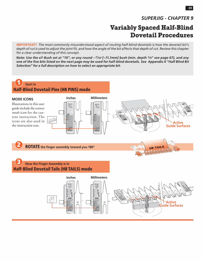
Variably Spaced Half-BlindDovetail Procedures
SUPERJIG - CHAPTER 9
Start in
Half-Blind Dovetail Pins (HB PINS) mode
ROTATE the finger assembly toward you 180°
MODE ICONSIllustrations in this user guide include the correct mode icon for the cur-rent instruction. The icons are also used in the instruction text.
Inches Millimeters
HB TAILS
HB PINS
1
ActiveGuide Surfaces
2
Now the Finger Assembly is in
Half-Blind Dovetail Tails (HB TAILS) mode3
Inches Millimeters
ActiveGuide Surfaces
IMPORTANT! The most commonly misunderstood aspect of routing half-blind dovetails is how the dovetail bit’s depth of cut is used to adjust the joint fit, and how the angle of the bit affects that depth of cut. Review this chapter for a clear understanding of this concept.
Note: Use the e7-Bush set at “10”, or any round ~7/16"[~11,1mm] bush (min. depth 1/4" see page 67), and any one of the five bits listed on the next page may be used for half-blind dovetails. See Appendix II “Half Blind Bit Selection” for a full description on how to select an appropriate bit.
29

VARIABLY SPACED HALF-BLIND DOVETAIL PROCEDURES30 Chapter 9 SuperJig-12-18-24 User Guide
Pins h Pin sockets Half-pins Half-pin sockets
Tails H Tail sockets ➆ Depth of Cut (tails)➇ Depth of Cut (pins)
13
5
7
8Depth of Cut
Depth of Cut
22
6
4
14˚
120-8
7/16" [11mm]
12˚
112-8
1/2" [13mm]
10˚
101-8
5/8" [16mm]
128-8
3/8" [9mm]1 /8
" [3,
2mm
] Min
.
Boar
d Th
ickn
ess
18˚
80-8
8˚
3/4" [19mm]
1 /8" [
3,2m
m] M
in.
Boar
d Th
ickn
ess
DEPTHOF CUT
DEPTHOF CUT
Bit selection is critical. You need to select a specific dovetail bit for your half-blind dovetail project, depending on the pinboard (drawer front) thick-ness you are using.
• Choose one of the five 1 ⁄2" [12,7mm] diameter dovetail bits shown above. Check bit selection in Appendix II.
• Depth of cut must be as specified for each of the five bits illustrated above. Note: Leigh bits 101-8, 112-8 and 128-8 are optional.
• Raising the bit above its specified cutting depth will result in loose joints and may damage the jig, bit and/or guidebush. A lower setting
will result in tighter joints that may not fit together.
• Small Depth of Cut adjustments will change joint fit tightness. See why in Steps 9-3 to 9-5.
• Half-blind PINS and TAILS are routed with the same dovetail bit and must be at the same Depth of Cut.
• All half-blind dovetail bits work with the Leigh e7-Bush supplied with your Leigh jig or standard ~7⁄16"[11,1mm] outside diameter guidebush.
Important! Read This About HB Depth of Cut
9-1 Half-Blind Dovetail Terminology:
The pins fit in the pin sockets. Joints almost always begin and end with a half-pin as shown.
2 1
3
PINBOARD THICKNESS determines the maximum depth of cut you can use. Select a bit with a specified cutting depth that is at least 1 ⁄ 8" less than the pinboard thickness.
A dovetail bit will produce only one spe-cific cutting depth.
Only 1 ⁄ 2" [12,7mm] cutting diameter bits can be used for half-blind dovetails.
Note: Add at least 1⁄8"[3,2mm] to the depth of cut for board thickness.
9-2 Cutting Depth for Variably Spaced Half-Blind Dovetails
Symbol for “approximately”

31VARIABLY SPACED HALF-BLIND DOVETAIL PROCEDURES Chapter 9SuperJig-12-18-24 User Guide
9-3 Joint Fit and Depth of CutHere’s why the depth of cut changes the fit in half-blind dove-tails. Increasing or decreasing the depth of cut does not affect the pin socket width , but does affect the width of the pin that goes into the socket .
1 3
2
1
1
3
2
1
PIN
2
1 3
1
9-4 Note that decreasing the bit depth makes the pin narrower while the pin socket stays the same width, producing a loose fit.Decreasing the bit depth (i.e. raise the bit into the router) pro-duces a looser fit.
9-5 Increasing the bit depth makes the pin larger while the pin socket stays the same width, producing too tight a fit.Increasing the bit depth (i.e. lower the bit) produces a tighter fit.
9-6 Bit Angle and Depth of Cut Half-blind pins and tails are routed with the same dovetail bit, the same guidebush, and the same depth of cut. A different depth of cut requires a differ-ent angled bit. Leigh offers five different angled dovetail bits for a range of cut depths. A lesser angle, say 8˚, for a deeper cut ; a greater angle, say 18˚, for a shallower cut .
1
2
18˚
8˚
9-7 Cumulative plus/minus tolerances in routers, bits and guidebushes, make it impossible to state exact bit depth for first-time precision fit. All dovetail jigs require trial and error tests to attain fine fitting joints. The good news; we give a starting depth for each bit. Test and measure the successful ‘Best fit’ depth of cut or bit projection . Record for future first-time fits.

VARIABLY SPACED HALF-BLIND DOVETAIL PROCEDURES32 Chapter 9 SuperJig-12-18-24 User Guide
9-8 Routing a Test Joint Use the e7-Bush or a 7⁄16"[11,1mm] diameter bush (min. depth 1⁄ 4" see page 67) and No.120-8 1⁄2"[12,7mm] 14° dovetail bit. (80-series bits cut too deep for 3⁄4"[20mm] boards, see HB bits, Appendix II). Select several pieces of 3⁄4"x5 1⁄2"[20x140mm] x about 8"[200mm], and the plastic bridge. Note: Half-blind pin boards must be minimum ½"[13mm] thick to clamp. Thinner boards; see 9-21.
9-10 Mount the finger assembly on the support brackets in the
HHB TAILS mode, flat on the spacer board, scales set on the thickness of the tail board (3⁄4"[20mm] in this instance).The HHB TAILS scale is always set at the tail board thick-ness.
9-11 Measure and mark a line on the inside face of the tail board to the bit’s depth of cut as in 9-2. Clamp this test tail board in the left front clamp, against the side stop with the top edge flush under the guidefingers, and the inside face i of the drawer side away from the jig.
1
9-12 Unlock and raise the finger assembly support brackets slightly so that the finger assembly is about 1⁄16"[2mm] above the boards. This will allow easy movement of the guidefingers.
1
9-13 The following joint design is suggested for this trial. It has a typical and traditional even layout of pins, with half-pins at each edge. The Leigh jig, however, allows for an infinite variety of joint designs, and boards of different thicknesses can be joined to each other as shown in this illustration. Before attempting joints of asymmetrical design, see chapter 12.
9-9 Clamp the spacer board in the rear clamp.

33VARIABLY SPACED HALF-BLIND DOVETAIL PROCEDURES Chapter 9SuperJig-12-18-24 User Guide
9-14 Ignoring the extreme outer guidefinger next to the scale (which just supports the router), loosen enough of the adja-cent guides to give the required pin socket layout. The half-pin guidefinger position illustrated will give a half-pin socket profile like that shown (dotted lines).
9-15 If the gaps between the guidefinger tails are wider than about 1⁄8"[3mm], mark off and cut some pieces of bridge extrusion to fit into the slots in the ends of the guidefinger tails. Cut the pieces a "bare" 1⁄8"[3mm] more than the distance between the fingers . They are a firm friction fit.After completing a project, save the bridge pieces for future use.
1
2
9-16 Remember to tighten any loose guidefingers. Lower the finger assembly back onto the spacer board and workpiece. It must touch the workpiece or the depth of cut will vary and the joint won’t fit. The scale should be set on the tailboard thickness, in this case 3⁄4"[20mm].
9-17 Attach the provided e7-Bush or a 7⁄16"[11,1mm] diameter bush securely to the router. No guidebush adjustment is required with half-blind dovetails.Fit the selected dovetail bit to the router.
REMEMBER SAFETY!
9-18 Adjust the bit height until the bit tip is level with the marked line . For the first light cut move the router from right to left. Make sure you control it firmly, because it is driven in this direction by the bit. Only the tip of the bit should be cutting on the first cut . This back or climb routing leaves a very clean shoulder in side grain.
9-19 Now rout in and out from left to right following the guides and bridge pieces to rout out the pin sockets, leaving the tails.See Hints and Tips 15-11.
2
1

VARIABLY SPACED HALF-BLIND DOVETAIL PROCEDURES34 Chapter 9 SuperJig-12-18-24 User Guide
9-20 Remove the test tail board, then clamp a scrap board in the front of the jig so that the top edge projects above the top face of the jig by about 1⁄8"[3mm] . This will keep the scrap piece below the path of the bit when routing the pin board.Remove the spacer board from the rear clamp.
1
9-21 If you're mounting Thin Pin Boards:Minimum recommended pin board thickness is 1⁄2"[13mm]. Remember, No.128-8 bits rout at 3⁄8"[9,5mm] deep. If you rout a pin board less than minimum thickness , you need to pack the board up from the jig body. We suggest a piece of 1⁄4" to 3⁄8"[6 to 9mm] plywood for this purpose .
2
1
9-22 Flush Drawers Place a test pin board in the left rear clamp against the side stop, its front end edge flush to the vertical board, the inside face i of the drawer front away from the jig body. The pin board is now positioned with the edge to be routed flush with the jig’s front face, correctly registered for the scale readings. For rabbeted drawer fronts, see Chapter 11.
1
9-23 Rotate the finger assembly to hHB PINS mode. Set the HB pins scale equal to tail board thickness (i.e., same setting as tails: this example, 3⁄4"[20mm]). HB pins and HB tail scales are always set to tail board thickness. Make sure the finger assembly is flush and level on the pin board. The guidefingers must touch the pin board or depth of cut will vary, causing poor joint fit.
9-24 If you have difficulty leveling the finger assembly on a nar-row workpiece, place a board the same thickness as the pin board under the other end of the finger assembly, but not in the rear clamp.
9-25 Rout out the waste between the pins. Rout each space from left to right. Do not back-rout on end grain. If the bit enters on the right side of the opening there will be a very strong pull to the left, so… rout each opening in at least three or four passes, left to right.

35VARIABLY SPACED HALF-BLIND DOVETAIL PROCEDURES Chapter 9SuperJig-12-18-24 User Guide
1
3
2
9-28 When you have the proper tightness of fit, check the flush-ness. The tails should be under flush to the pins by no more than 1⁄64"[0,3mm] to allow for cleanup (exaggerated here). Any concen-tricity errors in the collet and guidebush on different routers will affect this tolerance.
1/64[0,3mm]
9-29 If the tails stand out from the pins, set the hHB PINS scale away from the operator by the amount required.
9-30 If the tails fit in too far past the pins ends, set the hHB PINS scale toward the operator by the amount required. These adjustments for “flushness” are made only in the hHB PINS mode.
1/64"[0,3mm]
9-31 To make a box, rout all four ends of the tail boards, keeping the inside face i of the tail boards away from the jig.
9-26 Remove the pin board and test the joint for fit. If the joint is loose, as shown here, you need to lower the bit by the same amount as the gap at the bottom of the pins (when the pins are pulled against the socket sides ). If the joint is too tight, raise the bit slightly. Test again. You cannot rout the same board twice with a dovetail bit, so use two fresh board ends for each test.
90o
1
2
9-27 Keep the test tail board that fits well, and mark it with the number of the bit you used to rout it. For quick set-up next time, clamp this tail board in the jig as a depth-of-cut gauge to show how far to lower the bit. Better yet, measure the bit projection from the end of the guidebush or guidebush flange and record this for fast set-ups in future.

VARIABLY SPACED HALF-BLIND DOVETAIL PROCEDURES36 Chapter 9 SuperJig-12-18-24 User Guide
QUICK REFERENCE REMINDERS
9-32 Rout all four ends of the pin boards keeping the inside face i of the boards away from the jig. Note: When making drawers you may prefer to use through dovetails on the rear corners.
9-33 Assemble the box. As with through dovetails, it doesn't matter which edge of any of the boards are at the top or bottom, the box will still fit together e.g. pin board “A” can be up either way.
X
A
A
X
Y
Y
1
9-QR1 Half-blind (HB) tails: Drawer sides (tailboards) are clamped vertically in the jig. The inside face i of the drawer side goes away from the jig body. The finger assembly is in the
HHB TAILS mode, set to the thickness of the drawer side. Use bridge pieces where required .
9-QR2 Half-blind (HB) pins: Drawer fronts (pinboards) are cut with the board clamped horizontally in the jig. The inside face i of the drawer front faces away from the jig body. The finger assembly is in the hHB PINS mode, and again set on the thickness of the drawer side (but adjusted for a flush fit, see 9-28 to 9-31).
9-QR3 On the Leigh Superjig, all half-blind dovetails are routed using the e7-Bush or a 7⁄16"[11,1mm] diameter (min. depth 1⁄4" see page 67) bush. Instructions for end-on-end dovetails are at www.leighjigs.com/support.php. Scroll down Bulletins to “Superjig/D1600 End on End Dovetails”. ■
7/16"[11,1mm]
Thickness ofTail Board
Thickness ofPin Board
Depth of Cut
DovetailBit
GuidebushDiameter
up to 1"[26] 7/8" -1" [22] ~ 3/4" [19] No.80-8
up to 1"[26] 3/4" -up [20] ~ 5/8" [16] No.101-8 e7-Bush
up to 1"[26] 5/8" -up [16] ~ 1/2" [13] No.112-8 or
up to 1"[26] 9/16" -up [14] ~ 7/16" [11] No.120-8 ~‚7/16" [11,1]
up to 1"[26] 1/2" -up[12] ~ 3/8" [9] No.128-8 guidebush

Single PassHalf-Blind Dovetails
SUPERJIG - CHAPTER 10
Why rout “single pass” dovetails on a variably spaced Leigh jig? Well, you just may need to reproduce or restore a late 19th or early 20th century drawer which has similar, machine made joints. Or, if you are making a lot of drawer boxes and are not so concerned with the traditional “hand-cut look”, then routing both drawer fronts and sides together does go a little faster.
MODE ICONSIllustrations in this user guide include the correct mode icon for the cur-rent instruction. The icons are also used in the instruction text.
Only one mode is required:
Half-Blind Dovetail Tails (HB TAILS) mode
Inches Millimeters
ActiveGuide Surfaces
37

SINGLE PASS HALF-BLIND DOVETAILS38 Chapter 10 SuperJig-12-18-24 User Guide
1
6
3
4
Depth
of Cut
Depth
of Cut7
8 225
IMPORTANT! Bit depths of cut for “single pass” dovetails are not the same as for variably spaced joints.
10-2 Cutting Depth for Single Pass Half-Blind Dovetails
Note: Add at least 1⁄8"[3,2mm] to the depth of cut for board thickness.
120-8
14˚
9/32" [7,13mm]
3/8"[9,52mm]
112-8
12˚
7/16"[11,1mm]
101-8
10˚
7/32"[5,56mm]
128-8
18˚
1 /8" [
3,2m
m] M
in.
Boar
d Th
ickn
ess
DEPTHOF CUT
1/2"[12,35mm]
80-8
8˚
DEPTHOF CUT
Boar
d Th
ickn
ess
1 /8" [
3,2m
m] M
in.
Symbol for “approximately”
• Depth of cut must be as specified for each of the five bits shown above. Exception: See fig.11-26. Note: Leigh bits 101-8, 112-8 and 128-8 are optional.
• Raising the bit above its specified cutting depth will result in loose joints and may damage the jig, bit and/or guidebush. A lower setting will result in tighter joints that may not fit together.
• Small Depth of Cut adjustments will allow for joint fit tightness. See why in Steps 9-3 to 9-5.
• Choose one of the five, 1⁄2"[12,7 mm] diameter dovetail bits shown above.
• Fit the provided Leigh e7‑Bush to the router as shown below and set at No.10, or use a standard 7⁄16"[11,1mm] guidebush (min. barrel depth 1/4" see page 67).
The pins fit in the pin sockets. Joints almost always begin and end with a half-pin as shown.
10-1 Single Pass Half-Blind Dovetail Terminology:
Pins h Pin sockets Half-pins Half-pin sockets
Tails H Tail sockets ➆ Depth of Cut (tails)➇ Depth of Cut (pins)

39SINGLE PASS HALF-BLIND DOVETAILS Chapter 10SuperJig-12-18-24 User Guide
10-3 Bit Angle and Depth of Cut. Half-blind pins and tails are routed with the same dovetail bit, the same guidebush, and the same depth of cut. A different depth of cut requires a differ-ent angled bit. Leigh offers five different angled dovetail bits for a range of cut depths. A lesser angle, say 8˚, for a deeper cut ; a greater angle, say 18˚, for a shallower cut .
1
2
18˚
8˚
10-4 Cumulative plus/minus tolerances in routers, bits and guidebushes, make it impossible to state exact bit depth for first-time precision fit. All dovetail jigs require trial and error tests to attain a fine fitting joint. The good news; we give a starting depth for each bit. Test and measure the successful ‘Best fit’ depth of cut or bit projection and record for future first-time fits.
1 2
10-5 Routing a Test Joint You need a router, the e7‑Bush set at No.10, the 80-8 1⁄2"[12,7mm] 8˚ dovetail bit, two 3⁄4"[19mm] thick pin boards and two 1⁄2" thick tail boards. The No.80-8 bit routs at a shallower ~1⁄2"[13mm] depth on single pass dovetails than on regular variably spaced joints. For this test, start with the No.80-8 bit projecting 1"[26mm] from the router base.
10-6 This is a typical fixed template comb type jig. The comb depth is usually dimensioned to suit the most popular drawer side thickness of 1⁄2"[12,7mm].
1
10-7 Superjig features two novel innovations.A Stop Rod inserted through the fingers limits router travel to allow the deep tail socket guides to function as a simple shallow fixed comb.
1
10-8 The Spacer in the #1 position, slipped into the left-hand front side stop correctly offsets drawer sides from drawer fronts . The Spacer stays in place for the complete procedure.The Stop Rod stores here and the Spacer here .
5
4
1
2
3

SINGLE PASS HALF-BLIND DOVETAILS40 Chapter 10 SuperJig-12-18-24 User Guide
10-9 Board Widths: To achieve equally sized half pins at each side of a fixed space joint, use chart width plus up to 1⁄4"[6mm], or chart width minus up to 1⁄8"[3mm]. This chart covers boards up to maximum width for each jig.Example: the 7"[178mm] can be up to 71⁄4"[184mm] or as small as 67⁄8"[175mm].Note: This test joint is for 3⁄4" thick drawer front, 1⁄2" thick drawer side and #80-8 dovetail bit. Scale settings and depth of cut will vary depending on bit selection and tail board thickness.
1
2 2 2
1
Board Width Chart Add up to ¼" [6mm] or subtract up to 1/8" [3mm]
7⁄ 8 [22] 6 1⁄ 8 [156] 11 3⁄8 [289] (SJ-18)
1 3⁄4 [44] 7 [178] 12 1⁄4 [311]
2 5⁄8 [67] 7 7⁄8 [200] 13 1⁄ 8 [333]
3 1⁄2 [89] 8 3⁄4 [222] (SJ-12) 14 [356] (SJ-24)
4 3⁄8 [111] 9 5⁄8 [244]
5 1⁄4 [133] 10 1⁄2 [267]
10-10 Slip the Spacer onto the left hand front side stop , note: No 1 to the top. With the finger assembly raised in the HHB Tails mode, clamp a drawer side in the front left side, against the Spacer and the top end edge slightly above the jig body top. Note: Drawer side thickness can be from 7⁄16" to 9⁄16"[6 to 14mm].See 10-26 for Drawer Sides (Tail Boards) thicker than 5/8".
1
10-11 Place the drawer front (from 1⁄2" to 1" thickness [16 to 25mm]) in the rear clamp. Clamp with the side edge against the left rear side stop, front end edge touching flush across the rear of the front board . Lower the finger assembly to the drawer front.! Board edges must be square.
1
1
10-12 If you're mounting Thin Pin Boards:Minimum recommended pin board thickness is 1⁄2"[13mm]. Remember, No.128-8 bits rout at 3⁄8"[9,5mm] deep. If you rout a pin board less than minimum thickness , you need to pack the board up from the jig body. We suggest a piece of 1⁄4" to 3⁄8"[6 to 9mm] plywood for this purpose .
2
1
10-13 Re-set the drawer side in the front clamp so that its top edge touches the guide fingers and is perfectly flush with the top face of the drawer front and the left edge is against the Spacer .! Board edges must be square.
11
2

41SINGLE PASS HALF-BLIND DOVETAILS Chapter 10SuperJig-12-18-24 User Guide
10-14 With the scale set on 1⁄2"[12,7mm], raise the finger assem-bly about 1⁄16"[2mm] above the drawer front . The scale is always set on the 1/2" mark when using the stop rod. See 10-26 for Drawer Sides (Tail Boards) thicker than 5/8".
1
10-15 Slide across enough guide fingers to cover the drawer front width. Position fingers tight together and center the group of fingers on the board .Depending on the exact board width, the outer fingers will either overhang, be inside, or flush with the board edges. Now add one more finger to the right of the group for routing the drawer side.
1
2
10-16 Tighten the finger’s screws. Move any spare fingers so that they will support the router and tighten all loose fingers.Lower the assembly flat onto the two work pieces.
REMEMBER SAFETY!
10-17 Insert the Stop Rod through the fingers.For the first light cut move the router from right to left. Make sure you control it firmly, because it is driven in this direction by the bit. Only the tip of the bit should be cutting on the first cut . This back, or climb routing, leaves a very clean shoulder when routing side grain.
1
10-18 Now rout in and out from left to right. Follow the guides into each finger opening to touch the stop rod. The pins, tails and sockets are formed simultaneously.
10-19 Remove the boards and test the joint for fit. If the joint is loose, as shown here, lower the bit by the same amount as the gap at the bottom of the pins when the pins are pulled against the socket sides . If the joint is too tight, raise the bit slightly.Test again. You cannot rout the same board ends again with a dovetail bit, so use two fresh ends for each test.
90o
1
2

SINGLE PASS HALF-BLIND DOVETAILS42 Chapter 10 SuperJig-12-18-24 User Guide
10-20 Keep the test tail board that fits well, and mark it with the number of the bit you used to rout it. For quick set-up next time, clamp this tail board in the jig as a depth-of-cut gauge to show how far to lower the bit. Better yet, measure the bit projec-tion from the end of the guidebush or guidebush flange and record this for fast set-ups in future.
1
3
2
10-21 When you have the proper tightness of fit, check the flushness. The tails should be under flush to the pins by no more than 1⁄ 64"[0,3mm] to allow for cleanup (exaggerated here). Any concentricity errors in the collet and guidebush on different routers will affect this tolerance.
1/64[0,3mm]
10-22 If the tails stand out from the pins, set the HHB TAILS scale away from the operator by half the amount required.
10-23 If the tails fit in too far past the pins ends, set the
HHB TAILS scale toward the operator by half the amount required.
1/64[0,3mm]
10-24 To make a box, repeat the procedure four times, ensuring that the drawer fronts, rears and sides are all rotated correctly in the jig, keeping the inside face i of the boards away from the jig.
10-25 Assemble the drawer. As with through dovetails, it doesn't matter which edge of any of the boards are at the top or bottom, the drawer will still fit together e.g. pin board “A” can be up either way.
X
A
A
X
Y
Y

43SINGLE PASS HALF-BLIND DOVETAILS Chapter 10SuperJig-12-18-24 User Guide
10-26 Tail Boards 5/8"[16mm] and thicker.Use the same procedure to rout “single pass” dovetails with side thicknesses from 5⁄8" to 1"[16 to 25mm] except: The stop rod is not used and the initial scale setting is 5⁄8"[16mm] for all boards . Hint: Set the e7-Bush to lower than 10 for deeper cuts in drawer fronts. ■
1

SINGLE PASS HALF-BLIND DOVETAILS44 Chapter 10 SuperJig-12-18-24 User Guide

RabbetedHalf-Blind Dovetails
SUPERJIG - CHAPTER 11
Before attempting rabbeted half-blind dovetails, first master the techniques of flush half-blind dovetails in Chapter 9, Variably Spaced Half-Blind Dovetails.
Note: Rabbeted half-blind dovetails cannot be routed in a single pass – the lip of a drawer front makes it impractical, as each piece would have to be routed separately, in which case it is easier to use the variably spaced method.
1
3
2
11-4 If the rabbet width is greater than the top side stop width of 3⁄8" , the drawer side (tailboard) must be blocked away from the front side stop (see 11-5) by exactly the width of the rabbet minus 3⁄8" . For example, a 5⁄8" rabbet would require the tailboard to be offset by an additional 1⁄4" .Make a spacer block of the required width and…
11-3 This brings the pin ends exactly in line with the front jig face , ensuring that the scale reading is accurate.
11-1 Provided the drawer front lip is 3⁄8"[9,5mm] or less in each direction , you can mount and rout rabbeted drawer fronts and sides exactly the same way as flush drawer fronts, except...
1
1
11-2 Rabbeted Pins You will need to block the scrap stop in the front of the jig out from the jig’s front face by exactly the width of the rabbet . An easy accurate way to do this is to rabbet the end of the scrap piece vertically over a dado blade or router bit at the same time as you rabbet the drawer front (horizontally) .
2
3
2
3
=
=
1
1
45

RABBETED HALF-BLIND DOVETAILS46 Chapter 11 SuperJig-12-18-24 User Guide
11-5 Stick the block to the jig face with double-sided tape, making sure it touches the side stop.
3
11-6 The drawer side will now be stepped in from the side stop by the width of the rabbet, bringing the sockets in line with the pins.
11-7 Make sure you select a dovetail bit that has a working depth of cut less than the rabbet height. Otherwise, you will rout into the rabbet.
11-8 It is difficult to clean up the drawer sides and front corner after assembling a rabbeted drawer, so make sure the fit is flush before you complete the drawers See 9-28 to 9-30. ■

Asymmetric Dovetails
SUPERJIG - CHAPTER 12
~=
~=
12-1 By symmetrical we mean a joint that looks or is approximately symmetrical about its center line but is probably not, and need not be precisely symmetrical. Using the Leigh jig, it is easy to cut a joint that looks symmetrical; the pins will always align perfectly with the tails cut at the same spacing. Remember, symmetry is only required for appearance, not for joinery reasons.
12-2 An asymmetrical joint has a deliberately uneven layout of pins and tails desired for a project design; for example, this drop-front drawer. The half-pin at the bottom of the drawer is much wider than the top half-pin. As the top edges of the front and sides are flush, it makes sense to use these edges against the side stops at each end of the jig. Here's how.
12-3 Mount the right-hand drawer sides and pins on the left end of the jig for routing, and…
12-4 Turn one tailboard (like turning a page in a book) to the right end of the jig. Now lay out the fingers at the right end to match the sockets already routed. Now simply rout the left front corner (tails and pins) on the right side of the jig.
For certain procedures, you will need to use both ends of the Leigh Superjig Jig. Asymmetrical joint layouts are one example. On the Superjig, no joints will be truly symmetrical, but they can look symmetrical. Apparent symmetry is desirable for aesthetic reasons, but is not required for strength. Be sure you have read and understood chapters 8 through 10 before attempting these procedures.
47

ASYMMETRIC DOVETAILS48 Chapter 12 SuperJig-12-18-24 User Guide
12-5 Another example of asymmetry is the top corners of a slant-front desk. The joints themselves may be symmetrical, but they must be routed on opposite ends of the jig because the sloped front edges will not register accurately against the fixed vertical side stops.
12-6 At the back of the desk both sides and top are flush, so the rear edges are set against the side stops. Place the left end of the top tail board against the left side stop e. Rout the tails.
12-7 The left side of the desk goes against the left side stop e. Rout the pins.
12-8 To lay out the joint at the right end of the jig, turn the left hand tailboard (like a book page) against the right side stop. Lay out the fingers over the pins you just cut.
12-9 Place the right side of desk against the right side stop f. Rout the pins.
12-10 Rotate the finger assembly to TD Tails mode. Clamp the tailboard in the left side of the jig and rout the tails. Then rotate the board and clamp against the right side stop to rout the tails in the other end.

49ASYMMETRIC DOVETAILS Chapter 12SuperJig-12-18-24 User Guide
12-11 Note: If, in the slant-front desk example, the pins were in the desk top and the tails in the sides, then all the parts would be routed in the opposite ends of the jig to those shown in the previous steps.
12-12 Asymmetric “Single Pass” DovetailsSingle pass dovetails become asymmetrical when a board width falls between joint pitch dimensions on the board width chart, page 40. Joint side edges will have a proper half pin on one side and an unattractive half-tail on the other . It is preferable to design drawer openings to suit the board width chart dimensions.
1
2
2
12-13 However, if this is not an option, the unattractive edge can be hidden from view at the bottom of drawers. Simply rout the right front and left rear drawer corners on the left side of the jig , and then…
1
1
3
12-14 …the left front and right rear drawer corners on the right side of the jig . The Spacer is used to offset the drawer sides at both ends of the jig . ■
3
2
2

ASYMMETRIC DOVETAILS50 Chapter 12 SuperJig-12-18-24 User Guide

Sliding Dovetails
SUPERJIG - CHAPTER 13
HB TAILS
With the Finger Assembly in
HALF-BLIND DOVETAIL TAILS (HB TAILS) mode, install the cross-cut fence
KEEP the finger assembly in the same mode
Sliding Dovetail slots are cut
across the board face.
Inches Millimetres
HB TAILS
ActiveGuide Surface
1
2
Sliding Dovetail tails are cut across the board end edge
3
Inches Millimetres
ActiveGuide Surface
51

SLIDING DOVETAILS52 Chapter 13 SuperJig-12-18-24 User Guide
13-1 With the finger assembly in the HHB TAILS mode, the cross cut fence fits into the recesses in the ends of the tail guides to allow routing of sliding dovetails.
Space the guides fairly evenly across the jig and firmly seat the fence into end of each guidefinger to ensure a straight cut.
13-2 Using the cross cut fence as a guide surface for the guidebush, you can make lateral router cuts across the faces of horizontal boards (dovetail slots), and...
13-3 Across the top ends of vertical boards to cut the tails. First rout one side ...
Then turn the board side-over-side to cut the other half of the tail .
1
2
13-4 Turn the e7‑Bush to “5” and use the No. 120-8, 1⁄2"x 14° bit for sliding dovetails. This e7‑Bush setting will allow for fine fit adjustment later.A standard ~7⁄16"[11,1mm] guidebush (min. depth 1/4" see page 67) can be used but without the fine adjustment provided by the e7‑Bush.
5
13-5 On a full width joint, the slot depth-of-cut should be no more than 1⁄3 the board thickness . If the tail board is a load-bearing horizontal member (e.g., bookshelf or step), make the tail fairly thick for good tail neck strength . Shorter sliding dovetails for less structural demand may be slightly deeper, with narrower profiles, especially if appearance is important (e.g., where narrow rails join wider boards).
3
2
2/3
1/31
13-6 Use 3⁄ 4"x51⁄2"[20x140mm] softwood to make two slot boards , plus one narrow test slot board , two tail boards and one narrow test tail board . The tail boards and test tail board must be exactly the same thickness. This will make two uprights and two shelves.
1
2
3
4
=

53SLIDING DOVETAILS Chapter 13SuperJig-12-18-24 User Guide
13-7 Marking Out: Do not mark the slot positions on the board faces, Mark the edges of both slot boards together for perfectly level shelves. Stay at least 7"[180mm] in from the ends for clamping on this test project. 13-25 describes how to rout close to both ends. Mark the narrow test slot board in the same way at several closely spaced random spots. This board is used only for setup.
13-8 On the test slot board only, square the marks across the face.
13-9 Mount the test slot board in the rear clamp, markings up . Mount a 3⁄4"[20mm] thick square-ended board vertically in the front clamp against the side stop, with the top edge butting the underside of the test board (yes, the 3⁄4"[20mm] thickness is important).
21
13-10 Position and clamp the test board so that one of the edge marks is in line with the outside edge of the vertical board .
3
13-11 With the finger assembly (including the cross cut fence) on the support brackets in the HHB TAILS mode, set the scale to 9⁄16"[14mm] . The routed slot will be close to centred on the slot line. Make sure the finger assembly is level and sitting flush on top of the board.
1
1
13-12 Adjust the bit so the cut depth is about 5⁄16"[8mm]. Rout from left to right maintaining light inward pressure of the guidebush on the fence. Rout in only about 1"[25mm] and back out again.
Do not lift the router.

SLIDING DOVETAILS54 Chapter 13 SuperJig-12-18-24 User Guide
13-13 Check to see if this short slot is centred on the pencil line. If not, adjust the finger assembly in or out and re-test on the other lines as necessary until the slot is centred. Lock the finger assembly in this position and record the setting for future reference.
13-14 Now rout sliding dovetail slots in the two main slot boards with the boards in the horizontal position in the rear clamp, slot side, that is inside face i up.The guidefingers must be flush on the board.
13-15 Replace the spacer board in the rear clamp, and with the finger assembly on the spacer board, mount a test tail board vertically in the front clamp, flush under the guidefingers. Either side can face out j.
13-16 The HHB TAILS scale is not designed for this mode, but it does allow you to make quick adjustments for tail size and joint fit on sliding dovetails.Adjust and set the finger assembly so it is clear that the routed tail will be too large for the slot.
2
1
13-17 Rout one side of the test tail board. Make one light pass from right to left (climb routing). Make sure you control it firmly, because it is driven in this direction by the bit. Only the tip of the bit should be cut‑ting on the first cut (see inset). This back or climb routing leaves a very clean shoulder in side grain.
13-18 Finish left to right, with the guidebush touching the fence. Turn the test tail board around in the jig and rout the other side in the same manner.

55SLIDING DOVETAILS Chapter 13SuperJig-12-18-24 User Guide
13-19 Test the joint for fit. The tail should be too big. If it is too small, adjust the finger assembly outward by at least half the difference and rout another test tail on the other end of this test board.
13-20 If the tail is too wide move the finger assembly in toward the jig by half the amount the tail is too wide . Rout the same test board again. Adjust and re-test until fit is slightly loose or slightly tight.
2
1
13-21 Note: the e7‑Bush adjustment for sliding dovetails works reverse to normal. Turn it down for tighter fit, up for looser. Adjust the e7‑Bush for a fine fit: If fit is loose, turn the bush lower; if fit is tight, turn it higher. When the fit is satisfactory, rout one end of a project tail board and test again. If the fit is good, rout all the other ends.
T I G HT
ERL
OO
S E R
13-22 Stopped Sliding DovetailsIf a stopped sliding dovetail is called for...
Measure from the outside tip of the dovetail bit to the edge of the router base.
13-23 Measure the same distance from where you want the slot stopped to a position on the finger assembly. Move a guidefinger to that point and mark the guidefinger with a felt pen as a visual router stop mark…
1 2 34
5 6 7 8
10 20 30 40 50 60 70 80 90 100 10 20 30 40 50 60 70 80 90 100
13-24 Or lightly clamp (with a soft‑jawed clamp) a short board to the finger assembly to act as a router stop.

SLIDING DOVETAILS56 Chapter 13 SuperJig-12-18-24 User Guide
13-25 Dovetail slots preferably are routed from left to right because the bit’s clockwise rotation pulls the guidebush against the fence. However; as when routing close to both ends of a board, it may be necessary to rout slots from right to left. Bit rotation will tend to pull the router away from the fence. Feed slower and maintain constant guidebush pressure against the fence. ■

Box Joints
SUPERJIG - CHAPTER 14
Concept of OperationThe first board is set against the side stop ➀.
The Spacer is used to space the guide fingers ➁.
The Spacer is also used on the side stop ➂ to accu-rately offset mating work pieces for correct board to board joint alignment.
1
2
3
1
2
3
Actual Joint Sizes
The Superjig finger assembly was originally designed solely for dovetailing. Adapting the assembly for box jointing was a serendipitous combination of luck (existing guides approximately the correct dimension) and clever design; the e7‑Bush and Spacer.
So the nominal 5 ⁄16" and 5 ⁄8"[8 and 16 mm] box joint sizes are actually 21⁄64" and 21⁄32" [8,3 and 16,7mm] respectively.
57

BOX JOINTS58 Chapter 14 SuperJig-12-18-24 User Guide
Sup
erJi
g 12
Sup
erJi
g 24
Sup
erJi
g 18
5/16" 5/8" 8mm 16mm
29/32
1 9/16
2 7/32
2 7/8
3 17/32
4 3/16
4 27/32
5 1/2
6 5/32
6 13/16
7 15/32
8 1/8
8 25/32
9 13/32
10 1/16 10 23/32
11 3/8
12 5/32
12 13/16
13 15/32
14 1/8
14 25/32
15 7/16
16 3/32
16 3/4
17 13/32
18 1/16
18 11/16
19 11/32
20
20 21/32
21 5/16
123456789
1011121314151617181920212223242526272829303132333435363738394041424344454647484950515253545556575859606162636465
1 1/4
1 29/32
2 9/16
3 7/32
3 7/8
4 1/2
5 5/32
5 13/16
6 15/32
7 1/8
7 25/32
8 7/16
9 3/32
9 3/4
10 13/32
11 1/16
11 27/32
12 1/2
13 5/32
13 25/32
14 7/16
15 3/32
15 3/4
16 13/32
17 1/16
17 23/32
18 3/8
19 1/32
19 11/16
20 11/32
21
1
2
3
4
5
6
7
8
9
10
11
12
13
14
15
16
17
18
19
20
21
22
23
24
25
26
27
28
29
30
31
32
1
2
3
4
5
6
7
8
9
10
11
12
13
14
15
16
17
18
19
20
21
22
23
24
25
26
27
28
29
30
31
32
2 9/16
3 7/8
5 5/32
6 15/32
7 25/32
9 3/32
10 13/32
11 27/32
13 5/32
14 7/16
15 3/4
17 1/16
18 3/8
19 11/16
21
1 29/32
3 7/32
4 1/2
5 13/16
7 1/8
8 7/16
9 3/4
11 1/16
12 1/2
13 25/32
15 3/32
16 13/32
17 23/32
19 1/32
20 11/32
123456789
1011121314151617181920212223242526272829303132333435363738394041424344454647484950515253545556575859606162636465
32
48
65
82
98
114
131
148
164
181
198
214
231
248
264
281
301
318
334
350
367
383
400
417
433
450
467
483
500
517
533
23
40
56
73
90
106
123
140
156
173
190
206
223
239
256
272
289
309
325
342
359
375
392
409
425
442
459
475
491
508
525
541
65
98
131
164
198
231
264
301
334
367
400
433
467
500
533
48
82
114
148
181
214
248
281
318
350
383
417
450
483
517
Symmetrical Symmetrical Asymmetrical Symmetrical Asymmetrical SymmetricalAsymmetrical Asymmetrical
Board Width - INCHES Board Width - MILLIMETERS
Choose your Board Width:
Symmetrical joints: Use the red columnAsymmetrical joints: Use the grey columnCount the total sockets and pins in the first (white) column

59BOX JOINTS Chapter 14SuperJig-12-18-24 User Guide
14-1 Bit and Guidebush selection Only the e7‑Bush and 5⁄16" bit that came with Superjig ➀ are required for all Superjig box joints. Note: Spiral upcut router bits ➁ will cut cleaner than straight flute. Where metric size bits are available an 8mm straight or spiral bit may be substituted for the 5⁄16". Always start test rout-ing with the e7‑Bush set on “5”, the adjustment mid-range.
5
1 21
14-2 5⁄16"[8mm] Box Joints.Place the finger assembly on the support brackets in the HB TAILS mode, set the scales on the small triangular arrow ➀ and lower the assembly onto the spacer board.
1
1
14-3 Clamp a test board in the front left clamp, against the side stop with the top edge flush under the guidefingers. The board may be clamped face side in or out j. Mark and adjust the depth of cut to suit the thickness of the mating boards ➀.
14-4 Raise the finger assembly about 1⁄16"[2mm] to allow ease of guide finger adjustment ➀. Position the second guidefinger 1⁄32"[1,0mm] in from the board edge ➁ and tighten the finger. The first finger stays against the scale block as a router support ➂.Note: Square ended boards are essential to achieve flush joint align-ment.
1 23
14-5 Place the Spacer on the finger bar to the right of the second finger, numeral 1 on top overlapping the locked finger ➀. Move the next finger in to touch the Spacer ➁. Hold the guidefinger firmly against the Spacer and tighten the second finger screw ➂. As you remove the Spacer you should feel some friction; this indicates that the guidefinger is correctly spaced ➃.
12
3
4
14-6 Repeat this procedure across the jig until there is at least one guidefinger spaced past the right side of the work piece ➀. Tighten the unused guides. Store the Spacer on the outside of a rear side stop ➁.
12

BOX JOINTS60 Chapter 14 SuperJig-12-18-24 User Guide
14-7 Lower the finger assembly onto the spacer board and double-check that the bit depth is down to the center of the pencil line ➀. Make sure the collet does not rub on the guidebush.
1
14-8 Rout one end of the scrap board. Rout into each finger opening and between each finger. Make sure to run the guidebush on both sides of each opening.
14-9 Remove the board and fit the Spacer to the front side stop with the number 2 showing ➀. Make sure it is fully home.Clamp the second test board with its side edge against the Spacer and its top edge touching the guidefingers. Rout this board.Note: Square ended boards are essential to achieve flush joint align-ment.
1
14-10 Test the two boards for fit and flushness. If the joint is loose, turn the e7‑Bush to a higher number, say “6” and rout two more board ends. If the joint is too tight, turn the e7‑Bush to a lower number, say “4”. Trial and error establish the best e7‑Bush setting and record this in the space provided here, and/or on the pull‑out. Next time this setting will get a good first-time result
14-11 If the joint is over-flush ➀, raise the bit slightly. If it is under-flush ➁, lower the bit.
1 2
14-12 Let’s make a box.Prepare four boards and number them 1 to 4. Then select the grain alignment and mark the common top (or bottom) edge. Don’t worry about face side selection; this can be done after routing.
4
32
32
1 4
1

61BOX JOINTS Chapter 14SuperJig-12-18-24 User Guide
14-13 All box joint boards are clamped alternating face side in and face side out [icon] always with the same side edge against the side stop (or Spacer).
3
1
14-14 Rout both ends of boards 1 and 3 with their edges against the side stop. Be sure to keep the same edge to the stop.
14-15 Rout both ends of boards 2 and 4 with their edges against the Spacer and the Spacer in the No.2 position.Keep the same edges to the Spacer.
42
14-16 Keeping the marked side stop edges of all boards toward the top (or all to the bottom) of the box, select the preferred outside faces before routing the grooves ➄ for the bottom.
5
1
2 3
4
14-17 The same method will produce end-on-end joints. 14-18 5⁄8"[16mm] Box Joints Set up and space the guide fingers exactly as for 5⁄16"[8mm] joints. Start with the same e7‑Bush setting. See 14-4 thru 14-10.Prepare four boards using the board width chart for 5⁄8"[16mm] joints and number them 1 to 4 around the box ➀ with the com-mon edges marked.
4
4
3
3
2
2
1
1

BOX JOINTS62 Chapter 14 SuperJig-12-18-24 User Guide
14-19 Rout both ends of boards 1 and 3 but only rout between the guide finger sides ➀ not between the finger openings ➁. Keep the common edge against the side stop Hint: Mark the router base at the 12 o’clock position ➂ and steer this mark between the pointed ends of the fingers at the rear of the assembly.
21
21
21
3
2
14-20 Now rout both ends of boards 2 and 4, with the common edge against the side stop but only rout between the finger open‑ings ➀ not between the finger sides ➁. Hint: Now steer the base 12 o’clock mark along the finger points ➂.
2 2 2 2
3
1 1 1 1 1
14-21 Fit the Spacer to the side stop with number 2 showing. Now rout both ends of boards 1 and 3 again, with the common edge against the Spacer and again …only rout between the guide finger sides ➀, not between the finger openings ➁, steering the router mark between the finger points ➂.
21
21
2 21 1
3
2
14-22 With the Spacer still in position rout both ends of boards 2 and 4, with the common edge against the Spacer and again, only rout between the finger openings ➀, steering the router mark along the finger points ➂.
2 2 2 2
3
1 1 1 1 1
14-23 Joint fit Check for joint fit as usual, and repeat testing if required.
12
3 4
14-24 Theoretically, there will be nothing in the 5⁄8"[16mm] sockets, literally a zero thickness wall, where the bit has passed by twice. However, routing tolerances can leave a very thin “wall” uncleared by routing. This can be quickly removed with a chisel or sandpaper. ■

Hints and Tips
SUPERJIG - CHAPTER 15
Here are some special techniques and ideas to help you get the most out of your Leigh Superjig.
1
15-1 Through Dovetail Pins With the straight bit, carefully climb‑rout from right to left. Make sure you control the router firmly when climb routing.Climb routing produces a nice clean shoulder at ➀.Note: For clarity, the guidebush is not shown in this sequence.
15-2 Rout through on the right side until the bit is clear of the workpiece. Move the bit to the left side and climb cut left to right.
15-3 Climb rout from left to right from the rear of the cut. Take care to control router.
15-4 Rout back through towards you on the left side.
63

HINTS AND TIPS64 Chapter 15 SuperJig-12-18-24 User Guide
15-5 Rout away the rest of the waste. Note: Spiral up‑cut straight bits (inset) generally rout more smoothly than the two‑flute carbide‑tipped bits. If you want to try them, you should be aware that while the high-speed steel bits take a better edge, they are much less durable than the more costly solid carbide type (Leigh bits 170 HSS or 170C solid carbide).
15-6 Preventing TD Pins Tearout To help prevent tearout at the back bottom part of a straight cut, scribe a line with your marking gauge across the back of the pin board at exactly the depth of cut.
15-7 Dovetail Tails Tearout With the dovetail bit, most tearout occurs at the top left exit of the cut.
15-8 To help prevent this, back up the cut with the end-grain of a horizontal board pushed against the back of the workpiece and held in the rear clamp. This board replaces the spacer board.
15-9 This same scrap piece can remain in place for successive cuts.
15-10 For vulnerable or that last piece of exotic wood, clamp horizontal scrap pieces to the front and back of the work piece. Make sure clamps are below the bit depth.PLYWOOD is not suitable for routing; the laminates are very prone to tearout. Either of these two procedures (15-10 or 15-11) are essential for plywood but provide no guarantee of success.

65HINTS AND TIPS Chapter 15SuperJig-12-18-24 User Guide
15-11 A single scrap piece can be C-clamped on the back of half-blind tails, but make sure you protect the workpiece from the clamp pads. Note: There’s no 100% solution to tearout. It’s not the jig’s fault, just something that happens when machining, sawing and even chiseling wood. Important pieces fall off from where you least want them to.
15-12 On face cuts, whether using a straight bit or a dovetail bit, climb routing or back routing will leave a clean edge; but great caution must be exercised in controlling the router’s movement from right to left, as the bit rotation pulls the router in that direction anyway.
15-13 General Hints For routing long vertical boards it may be necessary to build a jig stand to mount securely on your bench. Make the stand and bench height combination sufficient to accept the board length you have in mind. The jig stand should be bolted securely to the bench. Build a stable platform to stand on as in the illustration. Do not use a set of steps; they’re too unstable.
15-14 When placing long horizontal boards in the rear clamp, make sure the rear end of the board is supported to prevent unnec-essary racking of the jig.
15-15 Using The Router Mark the router base top edge at the 12 o’clock position with a felt marker pen. Without wood or bits, try some dry runs in each jig mode. This will soon get you used to positioning the guidebush against the correct guide surface without looking under the router.Do not rout at face level.
15-16 Some router bases have sharp edges on the outside and inside corners. A slight chamfer of the edges with a fine file or sandpaper block will ease router movement on the jig.An occasional light spray of TopCote® or application of soft wax to the router base makes for smooth, easy router movement on the jig. ■

HINTS AND TIPS66 Chapter 15 SuperJig-12-18-24 User Guide

Attaching the Leigh e‑Bushto the Router
SUPERJIG - Appendix I
e-Bush and Guidebush AdaptorsThe Leigh e-Bush fits directly to some popular routers such as Porter Cable, Black & Decker, and Dewalt. Many other makes, e.g. Bosch, Fein, Festool, Milwaukee etc., offer or come with base adaptors that accept the e-Bush. Leigh offers eight adaptors, plus the Bosch RA1100 and RA1126, allowing the use of over one hundred other router models, new and old. The 711C (~7⁄16" OD) may be used in place of the e7 for dovetails, however it does not allow fit adjustment for box joints. See the next page for a list of routers.
67
703
BoschRA1100(must be used with Bosch RA1126 holder)
e7-BushOptional 711C guide bushing is for dovetails only, not box joints
702R 706R
705R
710
Nut for e7 and 711C
704R
721
702
e-Bush Mounting Variations
e-Bush Adaptors
BoschRA1126(required for Bosch RA1100)
The e7 and 711C with Adaptor 710
The e7 and 711C with Adaptor 702 and 702R
The e7 and 711C fit directly to many routers
The e7 and 711C with Adaptor 703

ATTACHING THE LEIGH e‑Bush TO A ROUTER68 Appendix i SuperJig-12-18-24 User Guide
Template Guide Bushing and Adaptor Selection Your router may need an adaptor to mount the guide bushing. Find out with this chart. See www.leighjigs.com for the complete list of routers.
DIRECTIONS
A. Locate name of router maker in Column 1.
B. Locate router model in Column 2. If your router is not listed visit leighjigs.com for a complete, up-to-date list of routers.
C. Locate adaptor required for your router in Column 3.
• Order Leigh adaptors (part no’s in red) in Column 3 from Leigh.
• Order Bosch adaptors RA1100 and RA1126 in Column 3 from Leigh or your Bosch dealer.
• Order all other adaptors in Column 3 from the router manufacturer’s dealer.
Note: Adaptor mounting screws are included with router.
■ MAFELL – Rework adaptor slightly.
D. Guide bushings in Column 4 fit all adaptors listed and may be ordered if required.
◆ A ~7/16" e7 guide bushing is supplied with all Leigh Super jigs. Order only if you require a replacement.
All 8mm shank bits work with the e7-Bush supplied with your Leigh jig, or with any 7/16" OD guide bushing that has a min. barrel length of 1/4". No other guide bushing sizes can be used.
Note: The 711C (~7/16" OD guide bushing) has replaced the 711TP.
1 ROUTERMAKER
2 ROUTER MODEL
3 ROUTER ADAPTOR
4 7/16" OD BUSHING ◆
AEG
OFE 710 in plunge base Not Required e7 or 711C/711TP
OFSE 2000 703 e7 or 711C/711TP
RT1350E 706R e7 or 711C/711TP
BLACK & DECKER
All Professional, HD1250, RP400K,7614 Not Required e7 or 711C/711TP
6200 720673-00 e7 or 711C/711TP
SR100, 7AEE, KW780 series, KW 800, KW850 710 e7 or 711C/711TP
BOSCH
1600, 90085, 90088, 90098, 90140, 90150, 90300, 90303, 90305, 91264 Aftermarket base plate required e7 or 711C/711TP
1601, 1602, 1603, 1604, 1606, B1350 RA1110 e7 or 711C/711TP
North American ROUTERS PRODUCED AFTER mid-2010: 1613EVS, 1613AEVS, 1617, 1617EVS, 1618, 1618EVS, 1619EVS, MR23EVS, MRC23EVS, MRF23EVS,
MRP23EVS
RA1126 quick change adaptor and RA1100 bushing adaptor req’d
e7 or 711C/711TP
North American ROUTERS PRODUCED BEFORE mid-2010 and others available worldwide that include the RA1126 adaptor: 1613, 1613EVS, 1613AEVS,
1614, 1614EVS, 1617EVS, 1618EVS, 1619EVS, B1450, GOF900, GOF900CE, GOF900ACE, GOF1200, GOF1300CE, GOF1300ACE, GOF1600CE, GOF2000CE, GMF1400, GMF1600CE, POF800ACE, POF1100AE, POF1200AE, POF1400ACE
RA1100 e7 or 711C/711TP
1611, 1611EVS, 1615, 1615EVS, B1550, GOF1600, GOF1700ACE 702 e7 or 711C/711TP
CRAFTSMAN (SEARS)
All non-plunge models Aftermarket base plate required e7 or 711C/711TP
135275070 Plunge See Skil 1823 or 1835
Other plunge models 702 e7 or 711C/711TP
MD11 Plunge & Fixed Base. MD9.5 Fixed Base Not Required e7 or 711C/711TP
DEWALT
DW610, DW616, DW618 Not Required e7 or 711C/711TP
DW613, DW615(UK) 710 e7 or 711C/711TP
DW614, DW615, DW621, DW624, DW625, DW626 N. America Only, Supplied w/router e7 or 711C/711TP
DW621K & DW626 outside N. America 706R e7 or 711C/711TP
DW625 Type 1,2,3,5 outside N. America 702 e7 or 711C/711TP
DW624 & DW625 Type 4 outside N.America, DW625EK 702R e7 or 711C/711TP
ELU
OF15, OF15E, OF97, OF97E 706R e7 or 711C/711TP
MOF68, MOF69, MOF96, MOF96E 710 e7 or 711C/711TP
MOF131, MOF177 Type 1,2, & 3 702 e7 or 711C/711TP
MOF177 Type 4, MOF177EK 702R e7 or 711C/711TP
2720, 2721, 3328 Not Required e7 or 711C/711TP
3303, 3304 EO9600 or 761 270-00 e7 or 711C/711TP
3337, 3338, 3339 702 e7 or 711C/711TP
FEIN RT1800 Supplied w/router e7 or 711C/711TP
FESTOOL
OF1E , OF2E, OF650, OF900E ,OF1000, OF1010E 704R e7 or 711C/711TP
OF2000, OF2000E 705R e7 or 711C/711TP
OF1400 and OF2200 North America Only Supplied w/router e7 or 711C/711TP
OF1400 Outside North America 493566 e7 or 711C/711TP
OF2200 Outside North America494627 O-Ring may be required
to keep bushing centerede7 or 711C/711TP
FREUD FT700(2), FT2000, FT2200, FT3000 721 e7 or 711C/711TP
HITACHI
TR8, TR12, FM8, M8, M12 Series 325211 OR 703 e7 or 711C/711TP
M12VC, KM12SC, KM12VC Not Required e7 or 711C/711TP
M12SA2, M12V2 325224 e7 or 711C/711TP
MAFELL LO65E 702 ■ e7 or 711C/711TP
MAKITA
M363, MRP090, RP1800, RP1801, RP2301, RP2301FC, 3612C Europe Qk Fit Base 721 e7 or 711C/711TP
3600, 3606, 3608, 3612, 3612B, 3612BR, 3612C N. America, 3620, 3621, RP0900, RP900K
703 e7 or 711C/711TP
3601B 321 493-1 e7 or 711C/711TP
RP0910, RP1110C 706R e7 or 711C/711TP
RF1100, RF1101, RD1100, RD1101, RP1101 Not Required e7 or 711C/711TP
MASTERCRAFT Please contact Leigh for assistance
METABO OF1612, OFE1812 (for all others, please contact Leigh for assistance) 704R e7 or 711C/711TP
MILWAUKEE
5615, 5616, 5619 49-54-1040 e7 or 711C/711TP
5625 49-54-1026 e7 or 711C/711TP
5670 Not Required e7 or 711C/711TP
PERLES OF808 Series, OFE6990 710 e7 or 711C/711TP
PORTER CABLE (ROCKWELL)
All Not Required or Supplied w/router e7 or 711C/711TP
RIDGID R2930 (for all others, please contact Leigh for assistance) 704R e7 or 711C/711TP
RYOBI
R30, R50, R150, R151, RE155, R500, R501, R502 703 e7 or 711C/711TP
R600, R601, RE600, RE601 702 e7 or 711C/711TP
R160, R161, R162, R163K, R165, R170, R175, RE175, R180, R180PL, R181, R185, ERT1150
706R e7 or 711C/711TP
SKIL
1823 or 1835 91803 e7 or 711C/711TP
SK1810, 1815, 1820, 1825 RAS140 e7 or 711C/711TP
All others Aftermarket base plate required 11592
TREND T3, T4, T5, T9, T10, T11–UniBase required 710 e7 or 711C/711TP
TRITONTRC001 TGA006 or 704R e7 or 711C/711TP
JOF001, MOF001, TRA001Accessory Kit (includes adaptor)
TGA001 or TGA150e7 or 711C/711TP
WEGOMA OF850 Series 710 e7 or 711C/711TP

Bit Selection
SUPERJIG - Appendix II
Optional router bits for variably spaced through and half‑blind dovetails.
Bit Selection for Through Dovetails 8° Dovetail Bit for TailsThe pins ➀ must fit into the sockets ➁. So the dovetail bit’s depth of cut B must be equal to or a little greater than the pinboard thickness ➂. Measure the pinboard thickness ➂ and select the dovetail bit with
2
1
B
3
4
5
the correct depth of cut B from the following pages (bits must be 8° for through dovetails).
Straight Bit for PinsThe matching straight bit is listed just below the dovetail bits. The 5⁄16" diameter No. 140-8, 8mm shank is the only straight bit you need with the Superjig.
GuidebushAll joints on the Superjig are routed with the e7-Bush, or all but box joints with any ~7⁄16" OD guidebush (min. barrel depth 1⁄4"). See page 68.
Shank SelectionNote: You will require a router with an 8mm or 1⁄2"[12,7mm] collet to use our 8mm shank bits. For a 1⁄2"[12,7mm] collet router you will require our 1⁄2"[12,7mm] to 8mm collet reducer No. 172‑8. Note: This is a collet reducer ➃, not a collet ➄. It does not replace the collet, it slides directly into your 1⁄2" collet. Do not remove the collet nut when installing the collet reducer.
69
Through Dovetails

BIT SELECTION70 Appendix ii SuperJig-12-18-24 User Guide
You will note that some of the dovetail bits’ depths of cut overlap. For example:No. 80-8 bit (B): 1⁄2"– 13⁄16"[12 - 20mm]No. 70-8 bit (B): 1⁄4"– 1⁄2"[6 - 12mm]
This means that 1⁄ 2" boards can be joined using either the No. 80-8 and 140-8 combination, the No. 75-8 and 140-8 com-bination, or the No. 70-8 and 140-8 combination. The three bit combinations will produce slightly different-looking joints because each dovetail bit produces a different size pin:No. 70-8 3⁄8" ➀No. 75-8 7⁄16" ➁No. 80-8 1⁄2" ➂.
Do not attempt to rout dovetails at less than the minimum depth of cut specified.
2
3
1
Leigh Through Dovetail Bits
Note: Bit and joint drawings are about actual size.
Joint from Bit No. 80
A
BF
Cutter 140-8
CCutter 80-8 bw dim
C F
A
BDE
A B C D E F GuidebushBits Overall Diameter Cutting Depth Range Shank Diameters Shank Length Overall Length Angle DiameterNo. 80-8* 1/2" [12,7] 1/2" to 13/16" [13,0-20,6]** 8mm 1-3/4" [45,0] 2-9/16" [65,0] 8° e7 or 711C ~7/16" [11,1] No. 140-8* 5/16" [7,9] up to 1" [26,0] 8mm 1-3/4" [45,0] 2-3/4" [70,0] – e7 or 711C ~7/16" [11,1]
140-8
80-8
Joint from Bit No. 75-8
A
BF
Cutter 140-8
C Cutter 75-8 bw dim
C
BDE
A
F
A B C D E F GuidebushBits Overall Diameter Cutting Depth Range Shank Diameters Shank Length Overall Length Angle DiameterNo. 75-8 7/16" [11,1] 3/8" to 5/8" [9,5-16,0] 8mm 1-3/4" [45,0] 2-3/8" [60,0] 8° e7 or 711C ~7/16" [11,1] No. 140-8* 5/16" [7,9] up to 1" [26,0] 8mm 1-3/4" [45,0] 2-3/4" [70,0] – e7 or 711C ~7/16" [11,1]
140-8
75-8
Numbers in brackets are millimeters * Bits 80-8, 120-8, and 140-8 come standard with Leigh Super Jigs **Maximum pin board thickness = 13⁄16"
Included with
Superjig
Included with
Superjig
Included with
Superjig

71BIT SELECTION Appendix iiSuperJig-12-18-24 User Guide
Leigh Through Dovetail Bits
Joint from Bit No. 70
A
BF
Cutter 140-8
C Cutter 70-8 bw dim
C
DE
A
B
F
A B C D E F GuidebushBits Overall Diameter Cutting Depth Range Shank Diameters Shank Length Overall Length Angle DiameterNo. 70-8 3/8" [9,5] 1/4" to 1/2" [6,0-13,0] 8mm 1-3/4" [45,0] 2-1/4" [57,0] 8° e7 or 711C ~7/16" [11,1] No. 140-8* 5/16" [7,9] up to 1" [26,0] 8mm 1-3/4" [45,0] 2-3/4" [70,0] – e7 or 711C ~7/16" [11,1]
140-8
70-8
140-8
60-8
Numbers in brackets are millimeters * Bits 80-8, 120-8, and 140-8 come standard with Leigh Super Jigs
Joint from Bit No. 60
A
BF
Cutter 140-8
CCutter 60-8 bw dim
CF
A
BDE
A B C D E F GuidebushBits Overall Diameter Cutting Depth Range Shank Diameters Shank Length Overall Length Angle DiameterNo. 60-8 5/16" [7,9] up to 3/8" [9,5] 8mm 1-3/4" [45,0] 2-1/8" [54,0] 8° e7 or 711C ~7/16" [11,1] No. 140-8* 5/16" [7,9] up to 1" [26,0] 8mm 1-3/4" [45,0] 2-3/4" [70,0] – e7 or 711C ~7/16" [11,1]
Note: Bit and joint drawings are about actual size.
Joint from Bit No. 50
A
BF
Cutter 140-8
C Cutter 50-8 bw dim
C F
A
BDE
A B C D E F GuidebushBits Overall Diameter Cutting Depth Range Shank Diameters Shank Length Overall Length Angle DiameterNo. 50-8 1/4" [6,35] up to 1/4" [6,35] 8mm 1-3/4" [45,0] 2" [50,0] 8° e7 or 711C ~7/16" [11,1] No. 140-8* 5/16" [7,9] up to 1" [26,0] 8mm 1-3/4" [45,0] 2-3/4" [70,0] – e7 or 711C ~7/16" [11,1]
140-8
50-8
Included with
Superjig
Included with
Superjig
Included with
Superjig

BIT SELECTION72 Appendix ii SuperJig-12-18-24 User Guide
1
2
3
B
Bit Selection for Half-Blind DovetailsBoth parts of a half-blind dovetail are cut with the same dovetail bit. The dovetail bit’s working depth of cut B must be less than the pinboard thickness ➀ for flush drawers by at least 1⁄8"[2mm], and slightly less than the rabbet depth ➁ for rabbeted drawer fronts. Minimum pin board (drawer front) thickness is 1⁄2"[12mm].Drawer side thickness ➂ does not affect bit selection.Note: B is the nominal working depth for half‑blind
dovetails, not the maximum depth. B must not be varied, except for minor adjustments for joint fit. See page 35.Measure the drawer front thickness (minimum 1⁄2"[12mm]) ➀ or rabbet depth (minimum 7⁄16"[11,1mm]) ➁ and select the bit with the appropriate depth of cut B from one of the five bits on the following pages.
GuidebushAll joints on the Superjig are routed with the e7-Bush, or all but box joints with any 7⁄16" OD guidebush (min. barrel depth 1⁄4"). See page 68.
Shank SelectionNote: You will require a router with an 8mm or 1⁄2"[12,7mm] collet to use our 8mm shank bits. For a 1⁄2 "[12,7mm] collet you will require our 1⁄2"[12,7mm] to 8mm collet reducer No. 172‑8. Note: This is a collet reducer ➃, not a collet ➄. It does not replace the collet, it slides directly into your 1⁄2" collet. Do not remove the collet nut when installing the collet reducer.
4
5
Half-Blind Dovetails

73BIT SELECTION Appendix iiSuperJig-12-18-24 User Guide
A B C D E F GuidebushBits Overall Diameter Working Depth Shank Diameters Shank Length Overall Length Angle Diameter HB Variable HB 1-PassNo. 101-8 1/2" [12,7] ~5/8" [16,0] ~7/16"[11,1] 8mm 1-3/4" [45,0] 2-3/8" [60,0] 10° e7 or 711C ~7/16" [11,1]
Numbers in brackets are millimeters * Bits 80-8, 120-8, and 140-8 come standard with Leigh Super Jigs
Joint from Bit No. 80 for drawer front
A
B
F 80-8
Joint from Bit No. 101, 101-8
A
B
F
Cutter 101-8 bw dim
C F
A
BDE
101-8
112-8
Joint from Bit No. 112, 112-8
A
B
F
Cutter 112-8 bw dim
C F
A
BDE
Leigh Half-Blind Dovetail Bits
Note: Bit and joint drawings are about actual size.
A B C D E F GuidebushBits Overall Diameter Working Depth Shank Diameters Shank Length Overall Length Angle Diameter HB Variable HB 1-PassNo. 112-8 1/2" [12,7] ~1/2" [13,0] ~3/8" [9,5] 8mm 1-3/4" [44,0] 2-21/64" [59] 12° e7 or 711C ~7/16" [11,1]
Cutter 80-8 bw dim
C F
A
BDE
A B C D E F GuidebushBits Overall Diameter Working Depth Shank Diameters Shank Length Overall Length Angle Diameter HB Variable HB 1-PassNo. 80-8* 1/2" [12,7] ~3/4" [19] ~1/2" [12,7] 8mm 1-3/4" [45,0] 2-9/16" [65,0] 8° e7 or 711C ~7/16" [11,1]
Included with
Superjig

BIT SELECTION74 Appendix ii SuperJig-12-18-24 User Guide
Joint from Bit No. 128
A
B
F
Cutter 80-8 bw dim
C F
A
BDE
A B C D E F GuidebushBits Overall Diameter Working Depth Shank Diameters Shank Length Overall Length Angle Diameter HB Variable HB 1-PassNo. 128-8 1/2" [12,7] ~3/8" [9,5] 7/32"[5,5] 8mm 1-3/4" [45,0] 2-1/8" [54,0] 18° e7 or 711C ~7/16" [11,1]
128-8
Joint from Bit No. 120, 120-8
A
B
F
Cutter 120-8 bw dim
C F
A
BDE
120-8
A B C D E F GuidebushBits Overall Diameter Working Depth Shank Diameters Shank Length Overall Length Angle Diameter HB Variable HB 1-PassNo. 120-8* 1/2" [12,7] ~7/16" [11,0] ~9/32"[7,1mm] 8mm 1-3/4" [45,0] 2-1/4" [57] 14° e7 or 711C ~7/16" [11,1]
Note: Bit and joint drawings are about actual size.
Numbers in brackets are millimeters * Bits 80-8, 120-8, and 140-8 come standard with Leigh Super Jigs
Included with
Superjig

Jig Parts
SUPERJIG - Appendix III
75
See parts list and drawing on the following pages.
When ordering parts, please quote the jig model, serial number, part number, part description and quantity required. Pay particular attention to the scale measurement, and let us know if yours is inch or metric.

JIG PARTS LIST76 Appendix III SuperJig-12-18-24 User Guide
How to Order Parts Order directly from Leigh by calling toll free 800-663-8932, or if you’re outside North America contact your national distributor. Have your jig information ready — You’ll need the jig model, serial number, part number, part description and quantity required. Note: Place the finger assembly in half-blind mode to determine left hand and right hand scales.
PART DESCRIPTION QUANTITY PART NO. SUPER 12 SUPER 18 SUPER 24
Super Jig Front Body Extrusion 1 8012 8018 8024Super Jig Rear Body Extrusion 1 8112 8118 8124Fingers see model 7200 Quantity 13 Quantity 16 Quantity 19Finger Nuts (Threaded) see model 7210 Quantity 15 Quantity 18 Quantity 21Finger Washers see model 7215 Quantity 15 Quantity 18 Quantity 21Finger Wedges see model 7220 Quantity 15 Quantity 18 Quantity 218/32 x 7.35mm Finger Screws see model 7225R Quantity 15 Quantity 18 Quantity 21R.H. Inch Scale Assembly, complete (R.H. in H.B. Tail Mode) 1 7230or R.H. Metric Scale Assembly, complete (R.H. in H.B. Tail Mode) 1 7230ML.H. Inch Scale Assembly, complete (L.H. in H.B. Tail Mode) 1 7235or L.H. Metric Scale Assembly, complete (L.H. in H.B. Tail Mode) 1 7235MSJ End Housing R.H. 1 8005SJ End Housing L.H. 1 8010SJ Support Bracket R.H. 1 8050SJ Support Bracket L.H. 1 8060Scale Block R.H. (RH in HB Tail Mode) 1 7230Scale Block L.H. (LH in HB Tail Mode) 1 7235SJ Non-Slip Self Adhesive Strips 4 8712 8718 8724SJ Front Side Stops 2 8160SJ Rear Side Stops 2 8170SJ Spacer 1 8180Clamp Tube Extrusion - Front 1 8212 8218 8224Clamp Tube Extrusion - Rear 1 8312 8318 8324Clamp Tube End Plugs 4 7115Screwdriver 1 5501" Aluminum Finger Bar 1 8412 8418 8424Plastic Bridge Extrusions 3 8512 8518 8524Nylon Depth Rod 1 8612 8618 8624Support Bracket Knobs 2 7025Clamp Bar Springs 4 311Scale Thumb Screws 2 7250Scale Thumb Screw Washers 2 7255T-Bolts 4 7100End Housing Screws 12 71455/16"x18 Hex Nuts 4 3005/16" SAE Flat Washers 4 283SJ Hold Down Screws #10 x 1" 4 8145SJ User Guide 1 8200SJ Instructional Pull Out 1 8210Cam Clamps 4 7125Cam Nuts 5/16-18 4 7120SJ Instructional DVD 1 8250# 80-8 1/2" Dovetail Bit 1 80-8# 140-8 5/16" Straight Bit 1 140-8# 120-8 Dovetail Bit 1 120-81/2" to 8mm Collet Reducer 1 172-8e7 Oval Guide Bush & Nut 1 e7-BushPin Wrench 1 730V

77JIG PARTS LIST Appendix IIISuperJig-12-18-24 User Guide
8250
8200172-8
80-8
120-8
140-8
550
721572207210
7225R7200
721072207215
7225R
8312/ 8318/ 8324
711571207125
72357235M7250
80607255
283300
311
8170
71008180
8112/ 8118/ 8124
8412/ 8418/ 8424
8010
71457025
7100
2838160
300311
712571207115
8212/ 8218/ 8224
8512/ 8518/ 8524
8612/ 8618/ 8624
730V
8012/ 8018/ 8024
82108712/ 8718/ 8724
e7 8145
8005
72307230M
8050
(Threaded Nut)(Threaded Nut)
NOTE: When ordering parts, please quote the jig model, serial number, part number, part description and quantity required. Pay particular attention to the scale measurement, inch or metric.

JIG PARTS LIST78 Appendix III SuperJig-12-18-24 User Guide

Customer Support
SUPERJIG - Appendix IV
79
MAILING ADDRESS
Leigh Industries Ltd.
P.O. Box 357
Port Coquitlam, B.C.
Canada V3C 4K6
LOCATION
Leigh Industries Ltd.
1615 Industrial Ave.
Port Coquitlam, B.C.
Canada V3C 6M9
EMAIL/WEB
Customer Service [email protected]
Technical Support [email protected]
Websitewww.leighjigs.com
Manufacturer: Canada/USA
Our Commitment to You Leigh Industries takes pride in its commitment to providing excellence in customer service and support. This user guide is designed to provide you with the answers to any questions you have. However, if you require assistance, please feel free to contact our technical support staff or a distributor listed below.
AUSTRALIA & NEW ZEALANDCarba-Tec Pty. ltd.128 Ingleston Rd., Wakerley, Qld., 4154AustraliaTel: (07) 3390 5888Fax: (07) 3890 5280Order: 180 658 111Email: [email protected]: www.carbatec.com.au
CHINAHarvey Industries Co., Ltd.68-10 Suyuan AvenueJiangning District Nanjing 211100, ChinaTel: (0)86 5792 8869 / 5792 8021Fax: (0)86 5792 8826Email: [email protected]: www.harveyworks.cn
FRANCEEts Bordet23 Rue Traversiere93556 Montreuil Cedex, FranceTel: 01 48 58 28 39Fax: 01 48 58 48 58Email: [email protected]: www.bordet.fr/pages/
GERMANY, AUSTRIA & SWITZERLANDHacker GMBHHolzbearbeitungsmaschinenTraberhofstraße 103 D-83026 Rosenheim, DeutschlandTel: 08031 269650Fax: 08031 68221Email: [email protected]: www.leigh.de
ITALYFerrari Macchine Legno SRLVia Gallarata 74/76/7820019 Settimo M.se (MI) ItalyTel: 39 02 335 010 95Fax: 39 02 335 005 27Email: [email protected]: www.ferrarimacchine.com
JAPANOff Corporation Inc.323-1 Yanbara, Shimizu-ku, Shizuoka-shiShizuoka-ken, Japan 424-0002Tel: 81-054-367-6511Fax: 81-054-367-6515Email: [email protected]: www.off.co.jp
KOREALeigh Korea1st Floor, Yongyu Building, 25-3, Neung Pyung-Ri, Opo-Eup, Kwangju-Si, Kyunggi-do, KoreaTel: 82 (0) 70-8252-0988Fax: 82 (0) 31-765-5602Email: [email protected]: www.htools.co.kr
RUSSIAUnicom Ltd.Nikitskij Boulevard 12Moscow, 119019, RussiaTel: 7 (495) 690 0454Email: [email protected] (Russia)Email: [email protected] (Ukraine)Web: www.leighjigs.ru (Russia)Web: www.leighjigs.ua (Ukraine)
SOUTH AFRICAHardware Centre GroupPost: PO Box 4059, 2125Randburg, South AfricaTel: (011) 791-0844/46Fax: (011) 791-0850Email: [email protected]: www.hardwarecentre.co.za
SWEDENToolbox Sweden ABBruksgatan 3, S-597 30Atvidaberg, SwedenTel: 46 120 854 50Fax: 46 120 854 69Email: [email protected]: www.toolbox.se
UNITED KINGDOM & IRELANDAxminster Power Tool Centre Ltd.Unit 10, Weycroft AvenueAxminster, DevonEX13 5PH United KingdomTel: 03332 406406Email: [email protected]: axminster.co.uk/leigh
Printed in Canada© 2007 Leigh Industries Ltd. All rights reserved. No part of this publication may be reproduced, stored in a retrieval system, or transmitted in any form or by any means, electronic, mechanical, recording, or otherwise, without the prior written permission of Leigh Industries Ltd. 03/2015
Distributors
NOTE: Email can be useful, but technical queries usually raise queries from us. A phone call is the quickest and most convenient way to get queries answered, either directly to Leigh (toll free in N. America) or to your national distribu-tor. –Thanks!
TEL/FAX
Customer Service and Technical Support800-663-8932 (Canada/USA)604-464-2700 (Tel.)604 464-7404 (Fax.)

Printed in Canada
Joining Tradition with Today
Leigh Router Joinery Jigs
Copyright © 2022 FDOKUMEN