
dedicated freight corridor corporation of india limited - DFCCIL
304
DEDICATED FREIGHT CORRIDOR CORPORATION OF INDIA LIMITED (A GOVERNMENT OF INDIA ENTERPRISE) Under MINISTRY OF RAILWAYS Tender No.: DFCCIL/NOIDA UNIT / Electrical/ Substation /2022/02 Name of Work: Supply, Erection, Testing and Commissioning of 33 kV Sub-stations, DG Set and related works for DFCCIL Integrated Office Cum Residential Complex at Sec-145, Noida. E-TENDER DOCUMENT TECHNICAL BID (PACKET – A) FEBRUARY– 2022 Chief General Manager/DFCCIL Sector 145, Noida
-
Upload
khangminh22 -
Category
Documents
-
view
3 -
download
0
Transcript of dedicated freight corridor corporation of india limited - DFCCIL
DEDICATED FREIGHT CORRIDOR CORPORATION OF INDIA LIMITED
(A GOVERNMENT OF INDIA ENTERPRISE)
Under
MINISTRY OF RAILWAYS
Tender No.: DFCCIL/NOIDA UNIT / Electrical/ Substation /2022/02
Name of Work: Supply, Erection, Testing and Commissioning of 33 kV Sub-stations,
DG Set and related works for DFCCIL Integrated Office Cum
Residential Complex at Sec-145, Noida.
E-TENDER DOCUMENT
TECHNICAL BID
(PACKET – A)
FEBRUARY– 2022
Chief General Manager/DFCCIL
Sector 145, Noida
The tender for above work was floated earlier and awarded also, however it was cancelled/terminated as the successful contractor failed to take up the work. All bidders are hereby advised to go thorough the make list and technical specification of the tender document including BOQ very thoroghly and minutly. They should closely peruse specifications, scope of work, terms and conditions, all clauses etc. Tenderer may also visit the site to ascertain the site conditions and other related information. In case of any doubt, the bidders can contact at the address given in the tender document.
Information to Bidders
1
2
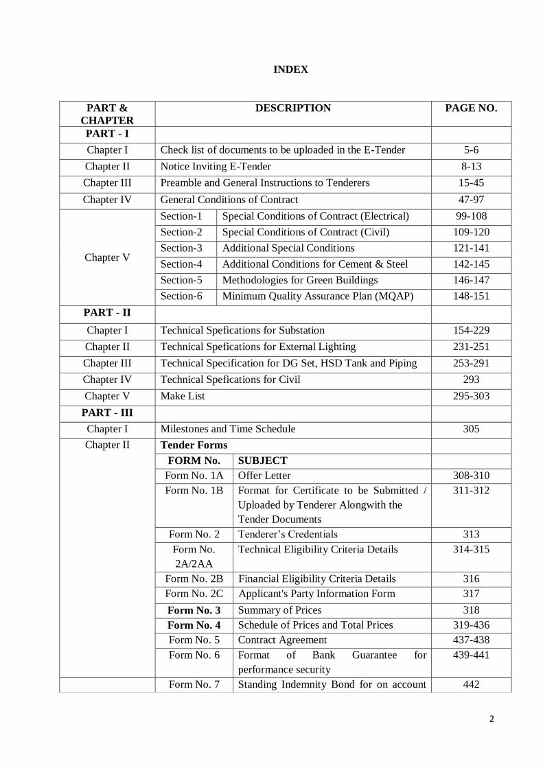
INDEX
PART &
CHAPTER
DESCRIPTION PAGE NO.
PART - I
Chapter I Check list of documents to be uploaded in the E-Tender 5-6
Chapter II Notice Inviting E-Tender 8-13
Chapter III Preamble and General Instructions to Tenderers 15-45
Chapter IV General Conditions of Contract 47-97
Chapter V
Section-1 Special Conditions of Contract (Electrical) 99-108
Section-2 Special Conditions of Contract (Civil) 109-120
Section-3 Additional Special Conditions 121-141
Section-4 Additional Conditions for Cement & Steel 142-145
Section-5 Methodologies for Green Buildings 146-147
Section-6 Minimum Quality Assurance Plan (MQAP) 148-151
PART - II
Chapter I Technical Spefications for Substation 154-229
Chapter II Technical Spefications for External Lighting 231-251
Chapter III Technical Specification for DG Set, HSD Tank and Piping 253-291
Chapter IV Technical Spefications for Civil 293
Chapter V Make List 295-303
PART - III
Chapter I Milestones and Time Schedule 305
Chapter II Tender Forms
FORM No. SUBJECT
Form No. 1A Offer Letter 308-310
Form No. 1B Format for Certificate to be Submitted /
Uploaded by Tenderer Alongwith the
Tender Documents
311-312
Form No. 2 Tenderer’s Credentials 313
Form No.
2A/2AA
Technical Eligibility Criteria Details 314-315
Form No. 2B Financial Eligibility Criteria Details 316
Form No. 2C Applicant's Party Information Form 317
Form No. 3 Summary of Prices 318
Form No. 4 Schedule of Prices and Total Prices 319-436
Form No. 5 Contract Agreement 437-438
Form No. 6 Format of Bank Guarantee for
performance security
439-441
Form No. 7 Standing Indemnity Bond for on account 442

3
payment
Form No. 7A Indemnity Bond 443
Form No. 8 ECS / NEFT / RTGS Mandate form 444
Form No. 9 Draft MOU for Joint Venture Participation 445-448
Form No.10 Format of JV Agreement 449
Form No.11 Proforma of Participation from each
partner of JV
450-451
Form No.12 Format for Power of Attorney for
authorized signatory of JV Partners
452
Form No.13 Format of Power of Attorney to lead
partner of JV
453-454
Form No. 14 Proforma for Time Extension 455-456
Form No. 15 Certificate of Fitness 457
Form No. 16 Proforma of 7 days Notice for works as a
Whole/In Parts
458
Form No. 17 Proforma of 48 Hours Notice for Whole
Work
459
Form No. 17A Proforma of 48 Hours Notice for part of
the Work
460
Form No. 18 Proforma of Termination Notice 461
Form No. 18A Proforma of Termination Notice for Part
of Work
462
Form No. 19 Pre-Contract Integrity Pact 463-470
Form No. 20 Final Supplemantary Agreement 471-472
Form No. 21 Deleted 473
Form No. 22 Format for Power of Attorney for
Authorized representative
474-475
Form No. 23 No deviation Certificate 476
Form No. 24 GUARANTEE BOND for water proffing
works / Anti Termite Treatment Works
477-478
Form No. 25 Agreement towards Waiver Under Section
12(5) and Section 31A (5) of Arbitration
and Conciliation Amendment Act
479
Form No. 26 Certification by Arbitrator appointed
under Clause 63 & 64 of General
Conditions of Contract
480-481
PART-IV Drawings 482-

4
PART-I
CHAPTER-I
CHECK LIST OF DOCUMENTS
TO BE UPLOADED
IN E-TENDER
5
PART-I
CHAPTER-I
CHECK LIST
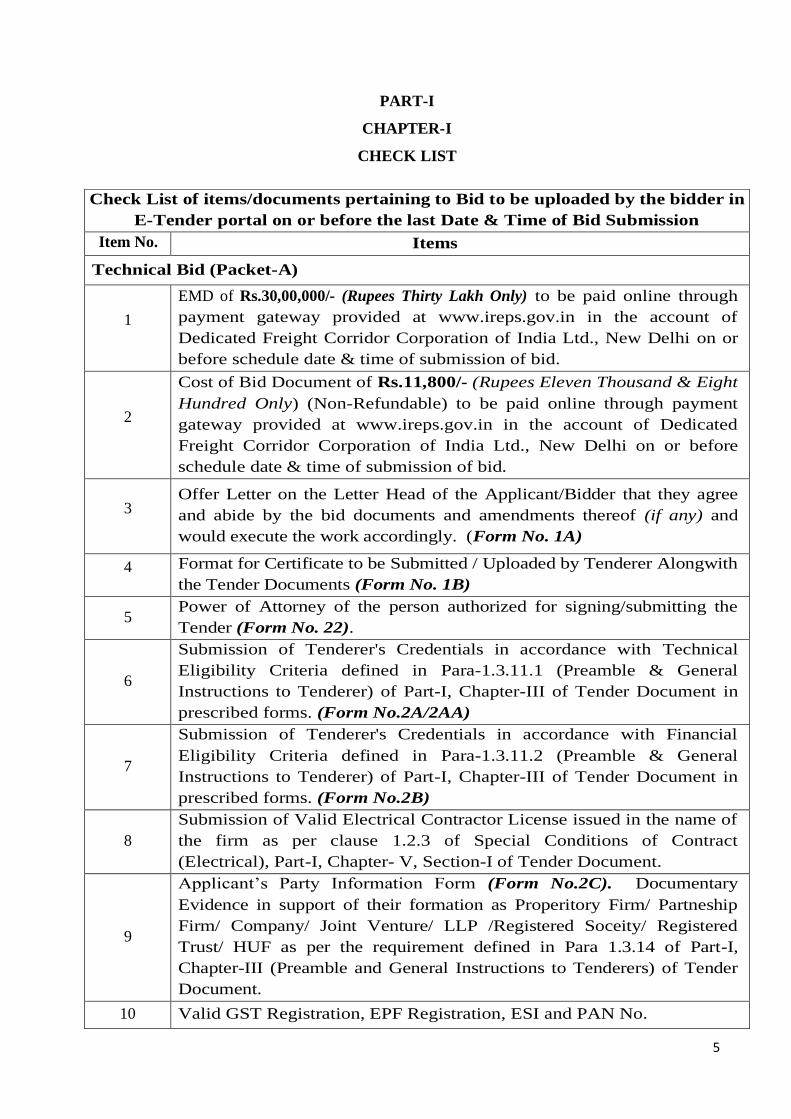
Check List of items/documents pertaining to Bid to be uploaded by the bidder in
E-Tender portal on or before the last Date & Time of Bid Submission
Item No. Items
Technical Bid (Packet-A)
1
EMD of Rs.30,00,000/- (Rupees Thirty Lakh Only) to be paid online through
payment gateway provided at www.ireps.gov.in in the account of
Dedicated Freight Corridor Corporation of India Ltd., New Delhi on or
before schedule date & time of submission of bid.
2
Cost of Bid Document of Rs.11,800/- (Rupees Eleven Thousand & Eight
Hundred Only) (Non-Refundable) to be paid online through payment
gateway provided at www.ireps.gov.in in the account of Dedicated
Freight Corridor Corporation of India Ltd., New Delhi on or before
schedule date & time of submission of bid.
3 Offer Letter on the Letter Head of the Applicant/Bidder that they agree
and abide by the bid documents and amendments thereof (if any) and
would execute the work accordingly. (Form No. 1A)
4 Format for Certificate to be Submitted / Uploaded by Tenderer Alongwith
the Tender Documents (Form No. 1B)
5 Power of Attorney of the person authorized for signing/submitting the
Tender (Form No. 22).
6
Submission of Tenderer's Credentials in accordance with Technical
Eligibility Criteria defined in Para-1.3.11.1 (Preamble & General
Instructions to Tenderer) of Part-I, Chapter-III of Tender Document in
prescribed forms. (Form No.2A/2AA)
7
Submission of Tenderer's Credentials in accordance with Financial
Eligibility Criteria defined in Para-1.3.11.2 (Preamble & General
Instructions to Tenderer) of Part-I, Chapter-III of Tender Document in
prescribed forms. (Form No.2B)
8
Submission of Valid Electrical Contractor License issued in the name of
the firm as per clause 1.2.3 of Special Conditions of Contract
(Electrical), Part-I, Chapter- V, Section-I of Tender Document.
9
Applicant’s Party Information Form (Form No.2C). Documentary
Evidence in support of their formation as Properitory Firm/ Partneship
Firm/ Company/ Joint Venture/ LLP /Registered Soceity/ Registered
Trust/ HUF as per the requirement defined in Para 1.3.14 of Part-I,
Chapter-III (Preamble and General Instructions to Tenderers) of Tender
Document.
10 Valid GST Registration, EPF Registration, ESI and PAN No.
6
IMPORTANT NOTES:
i. Document mentioned at S.No. 1 to 16 above of the Check list
[Technical Bid (Packet-A)] should be scanned and uploaded as
attachment at website (www.ireps.gov.in). The detailed instructions of
E-tendering can be read through website www.ireps.gov.in.
ii. Similarly, the document mentioned at S.No. 17 & 18 of the Check list
[Technical Bid (Packet-A)] should first be downloaded from E-Tender
Portal (in PDF Format) and thereafter upload them to E-Tender Portal,
through digital signature.
iii. For Document No. 19 of the Check list [Financial Bid (Packet-B)],
Financial Bid to be filled and submitted on www.ireps.gov.in by following
the steps available on the website.
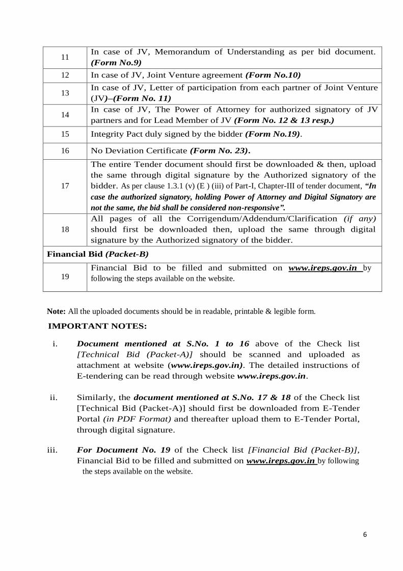
11 In case of JV, Memorandum of Understanding as per bid document.
(Form No.9)
12 In case of JV, Joint Venture agreement (Form No.10)
13 In case of JV, Letter of participation from each partner of Joint Venture
(JV)–(Form No. 11)
14 In case of JV, The Power of Attorney for authorized signatory of JV
partners and for Lead Member of JV (Form No. 12 & 13 resp.)
15 Integrity Pact duly signed by the bidder (Form No.19).
16 No Deviation Certificate (Form No. 23).
17
The entire Tender document should first be downloaded & then, upload
the same through digital signature by the Authorized signatory of the
bidder. As per clause 1.3.1 (v) (E ) (iii) of Part-I, Chapter-III of tender document, “In
case the authorized signatory, holding Power of Attorney and Digital Signatory are
not the same, the bid shall be considered non-responsive”.
18
All pages of all the Corrigendum/Addendum/Clarification (if any)
should first be downloaded then, upload the same through digital
signature by the Authorized signatory of the bidder.
Financial Bid (Packet-B)
19 Financial Bid to be filled and submitted on www.ireps.gov.in by
following the steps available on the website.
Note: All the uploaded documents should be in readable, printable & legible form.
7
PART-I
CHAPTER-II
NOTICE INVITING E-TENDER

8
PART – I
Chapter II
DEDICATED FREIGHT CORRIDOR CORPORATION OF INDIA LIMITED
(A GOVERNMENT OF INDIA ENTERPRISE)
Tender No: DFCCIL/NOIDA UNIT/Electrical/Substation/2022/02
NOTICE INVITING E-TENDER
National Competitive Bidding
Name of Work: Supply, Erection, Testing and Commissioning of 33 kV Sub-stations, DG
Set and related works for DFCCIL Integrated Office Cum Residential Complex at Sec-145,
Noida.
1.2.1 Chief General Manager/Noida, Dedicated Freight Corridor Corporation of India Limited,
D-89,1st Floor, Sector-2, Noida-201310, India, invites E-Tenders in single stage two packet
system on prescribed forms from Firms/Companies/Joint Ventures meeting requisite experience
and financial capacity for execution of the following work:
Tender No. DFCCIL/NOIDA UNIT/
ELECTRICAL/SUBSTATION/ 2022/02Name of Work Supply, Erection, Testing and Commissioning of 33 kV Sub-
stations, DG Set and related works for DFCCIL Integrated
Office Cum Residential Complex at Sec-145, Noida.
Employer/Client/Owner Dedicated Freight Corridor Corporation of India Ltd.
(DFCCIL), a Govt. of India (Ministry of Railways)
Enterprises through Chief General Manager/Noida, Sector 145,
Noida-201310.
Type of Tender Open E-Tender (Single stage two packet system)
Type of Contract Works Contract
Total Estimated Cost Rs. 18,27,43,008/- (Including GST@18%)
Completion Period of
Contract 09 Months
Defect liability period 12 Months from the date of issue of completion certificate of the
work by DFCCIL
Earnest Money Deposit EMD of Rs. 30,00,000/- (Rupees Thirty Lakh Only) to be paid
online through payment gateway provided at www.ireps.gov.in in
the account of Dedicated Freight Corridor Corporation of India
Ltd., New Delhi.
Note:
(i) Any firm recognized by Department of Industrial Policy

9
and Promotion (DIPP) as ‘Startups’ shall be exempted
from payment of Earnest Money on submission of
Registration Certificate issued by appropriate authority.
(ii) 100% Govt. owned PSUs shall be exempt from payment
of earnest money deposit.
(iii) Labour Corporate Societies shall deposit only 50% of
above earnest money deposit.
Cost of Tender Document
(Non-Refundable)
Rs. 11,800/- (Rs. 10,000/-+GST @ 18%) (Rs. Eleven Thousand
Eight Hundred only) to be paid online through payment gateway
provided at www.ireps.gov.in in the account of Dedicated Freight
Corridor Corporation of India Ltd., New Delhi.
Note: “No exemption is admisibile for cost of bid document and
shall not be claimed by bidder on the E-Tender portal”.
Validity of Offer 120 days
Security Deposit 5% of Contract value (as per clause 16. (1) of GCC).
Performance Bank
Guarantee
Performance Guarantee (PG) has to be submitted within
21(Twenty-One) days from the date of issue of Letter of
Acceptance (LOA), amounting to 3% of the contract value.
E-tendering website www.ireps.gov.in
For any help, please refer User Manuals containing the detailed
guidelines for E-Tendering available on www.ireps.gov.in >
Learning Centre and on Helpdesk of IREPS: 011-23761525.
Date & Time Schedule
Date of uploading of NIT/
Tender document (Online) On Date 23.02.2022
Pre-bid Meeting 01.03.2022 (Tuesday)
Last Date & Time of
Submission of Tender
On or before 21.03.2022 and time upto 15:00 hrs
Last date & time of
deposition of EMD & tender
document cost
On or before 21.03.2022 and time upto 15:00 hrs to be paid online through payment gateway provided at www.ireps.gov.in.
Date & Time of Opening of
Technical Bid (Online) On date 21.03.2022
Date & Time of
opening of Financial
Bid (online)
To be communicated later to only those bidders who are found
technically qualified after closure of Technical Evaluation.
Representative/Contact
Person of DFCCIL/Noida
Unit
Shri J V Rao
Assistant Project Manager-II/Electrical
Dedicated Freight Corridor Corporation of India Ltd. (Noida Unit)
Sector 145, Noida
Mobile No: 9911144941
E-MAIL ID:[email protected]
Address for Pre-Bid meeting
& opening of Tender Office of Chief General Manager/Noida Unit Dedicated
Freight Corridor Corporation of India Ltd.
Integrated Office Complex, Sector 145, NOIDA

10
1.2.2 Eligibility shall be assessed of applicants, fulfilling the technical capability and
competence as well as for financial and organizational resources as specified in
Clause no. 1.3.11 of Preamble and General Instruction to tenderers (Part -I, Chapter-
III of Tender Document). The tenderers are also required to fulfil the special technical
compliance as per Clause 2.1 of Special Conditions of Contract (Electrical), Part-I,
Chapter- V, Section-I of Tender Document.
1.2.3 Tender document can be viewed & obtained/downloaded from www.ireps.gov.in. The
cost of the tender document is Rs. 11,800/- which is non-refundable payable towards
the cost of one set of tender documents. The tender document shall have to be
purchased in the name of Firms/Company/Joint Venture and can be downloaded from
website www.ireps.gov.in. Tenderer are advised not to make any correction/addition/
alteration in the downloaded tender documents.
1.2.4 DFCCIL may issue addendum(s) / corrigendum(s) to the tender documents. In such
cases the addendum(s) / corrigendum(s) shall be issued and placed on
www.ireps.gov.in only before bidding start date of tender. The tenderers who have
purchased or downloaded the tender documents from the website before issue of
addendum(s)/corrigendum(s) must visit the website and ensure that such
addendum(s) / corrigendum (s) (if any) is also downloaded by them. Such
addendum(s)/corrigendum (s) (if any) shall also be submitted/uploaded duly stamped
and signed along with the submission of tender. Any tender submitted without
addendum(s) / corrigendum(s) (if any) is liable to be rejected.
1.2.5 The tender documents shall be submitted in online mode only through website
www.ireps.gov.in in two packets only viz Packet-A containing TECHNICAL BID
and Packet B containing FINANACIAL BID.
Bidder shall submit the Tender document cost & EMD (as mentioned in clause
1.3.4.1 & 1.3.4.2 of preamble & general instructions to tenderer, Part I, Chapter III
of Tender Document) on or before schedule date & time of submission of bid.
Financial Bid (as specified in “Financial Bid” in Tender Document) to be filled
and submitted on E-Tender portal www.ireps.gov.in by following the steps
available at E-Tender IREPS Portal.
Tender shall be submitted as per “General Instructions to Tenderers” forming as part
of the complete tender documents.
1.2.6 To participate in the E-Tender, it is mandatory for the bidders to get themselves
registered with the IREPS (www.ireps.gov.in) and to have user ID & password.
11
www.ireps.gov.in is the only website for submission of tender. ‘User Manuals’
containing the detailed guidelines for E-Tendering are available on www.ireps.gov.in
> Learning Centre.
It is mandatory for all Tenderers to have Class-III Digital Signature Certified from
any of the Licensed Certifying Agencies (‘CA’) to participate in E-Tendering of
DFCCIL, (Tenderer can see the list of Licensed CAs from the link www.cca.gov.in in
the name of the person who will submit the Online tender and is authorized to do so.
Tender shall be submitted through Online mode only at www.ireps.gov.in. Tender
submitted by any other mode will not be accepted. All the required documents
(legible) as mentioned in Check List have to be uploaded along with the offer on
www.ireps.gov.in failing which, the bid may not be considered.
1.2.7 Tenders shall be opened at the address given below on scheduled date & time in the
presence of the tenderers or their authorized representatives intending to attend the
opening.
Office of Chief General Manager/DFCCIL/Noida Unit
Sector 145, Noida-201310, U.P.
All the Bids received shall be opened on the date and time mentioned above in the
tender notice. Bid of the bidders shall be opened through process of e-tendering. The
sequence of opening shall be:
i) Earnest Money Deposit (EMD)and Tender Document Cost
ii) Technical Bid.
iii) Financial Bid (at a later stage after scrutiny & finalization of acceptable
Technical Bids)
1.2.8 Any tender received without Earnest money and cost of tender documents in the
form as specified in the tender documents shall not be considered and shall be
summarily rejected.
1.2.9 DFCCIL reserves the right to cancel the tender before submission/opening of tender,
postpone the tender submission / opening date and to accept / reject any or all tenders
without assigning any reason thereof. DFCCIL's assessment of suitability as per
eligibility criteria shall be final and binding.
1.2.10 Tenderers may note that they are liable to be disqualified at any time during tendering
process in case, any of the information furnished by them is not found to be true.
12
EMD of such tenderers shall be forfeited & the decision of DFCCIL in this regard
shall be final and binding.
1.2.11 DFCCIL reserves the right to pre-qualify the bidder(s) provisionally based on the
documents submitted by them in technical bid. Financial bids of only those bidders
would be opened, whose technical bids are found acceptable. In the event of any
document being found false (at a later stage), the provisional qualification shall stand
withdrawn, and the next lower bidder shall automatically come to the position of such
disqualified bidder. Also, action against such disqualified tenderer shall be taken as
per the provisions of the Tender.
1.2.12 Information as required as per various Forms of tender document should be submitted
by the tenderers without fail strictly as per formats.
1.2.13 The validity of offer shall be 120 days from the date of opening of the tender.
1.2.14 Transfer of the tender document purchased by intending tenderer to another tenderer
is not admissible. Tenderer can submit tenders only on the documents purchased
/downloaded from website: www.ireps.gov.in by them.
1.2.15 Tenderers must read all instructions regarding E-Tendering process on
www.ireps.gov.in ˃ Learning Centre ˃ E-Tender(Works) ˃ User Manual for
Contractor and INSTRUCTION TO TENDERERS Part I, Chapter III of the Tender
Document.
1.2.16 Tenderers are advised to regularly visit the E-Tender Portal (www.ireps.gov.in) for
information regarding tender, corrigendum, addendum (if any) etc.
1.2.17 Joint Venture are allowed in terms of Para 1.3.17 of Part-I, Chapter-III of the
Tender Document.
1.2.18 The rates quoted by the contract or are deemed to be inclusive of site clearance, setting
out work, profile, setting lay out on ground, establishment of reference benchmark(s),
installing various signage, taking spot levels, survey with total station, construction of
all safety and protection devices, compulsory use of helmet and safety shoes, and other
appropriate safety gadgets by workers, imparting continuous training for all the
workers, barriers, preparatory works, construction of clean, hygienic and well
ventilated workers housings in sufficient numbers working during monsoon or odd
season, working beyond normal hours, working at all depths, height, lead, lift, levels
and location etc. and any other unforeseen but essential incidental works required to
complete this work. Nothing extra shall be payable on this account and no extension
of time for completion of work shall be granted on these accounts.
In the Estimated Value of tender, GST @ 18% has been taken on the Basic Value.
The Basic Value is inclusive of all taxes, duties and levies except GST. The %
13
(above/below/at par) rates quoted by the tenderer shall apply on the Basic Value. The
GST as legally leviable and payable by the Bidder under the provisions of applicable
law/act shall be paid extra by DFCCIL.
The Bidders should quote their rates after considering the Input Tax Credits on
their input materials and services. Hence, Bidders should ensure that, full benefit of
Input Tax Credit (ITC) likely to be availed by them is duly considered while quoting
their rates.
1.2.19 Price Variation Clause (PVC) will be applicable for this work as per Clause 1.7 of
Special Conditions of Contract (Electrical) (Part-I, Chapter-V, Section-1 of
Tender Document).
1.2.20 Mobilization and Secured Advance will not be applicable for this work.
Chief General Manager/Noida
For & on behalf of DFCCIL
14
PART-I
CHAPTER-III
PREAMBLE & GENERAL INSTRUCTIONS TO TENDERERS
15
PART-I
Chapter- III
PREAMBLE & GENERAL INSTRUCTIONS TO TENDERERS
1.3.1 Introduction
(i) General
Ministry of Railways (MoR) established the Dedicated Freight Corridor Corporation
of India Limited (DFCCIL), a Schedule “A” Public Sector Undertaking wholly
owned by Ministry of Railways, Govt. of India to undertake planning &
development, mobilization of financial resources, construction, maintenance and
operation of the Dedicated Freight Corridor project. DFCCIL was incorporated as a
company under the Companies Act 1956 on 30th October 2006.
This company is now actively engaged in the implementation of Computerized Multi
Modal High Axle Load Dedicated Freight Corridor Project between Delhi-Mumbai
under the Western DFC Corridor and Ludhiana-Delhi-Kolkata under the Eastern
DFC Corridor.
The DFC project will also restore the Indian Railway’s competitive strength in the
freight transportation market and emerge as the major low carbon and energy
efficient transport system in the country. It will drive the establishment of industrial
corridors and logistic parks along its alignment and play a crucial role in supporting
India’s growing economy.
(ii) Project Concept
The work of “Supply, Erection, Testing and Commissioning of 33 kV Sub-
stations, DG Set and related works for DFCCIL Integrated Office Cum
Residential Complex at Sec-145, Noida.” is the part of Project “DFCCIL Integrated
Office Cum Residential Complex with Pre-Certified GRIHA 5 Star Rating” in the
National Capital Region at Noida-Greater Noida Expressway in village Jhatta,
Sector-145, Noida.
DFCCIL Management desire to build in phases a very vibrant and dynamic complex
which should be self-contained and self- sustaining, with state of art physical, social
and economic infrastructure. This complex would be developed on Green Building
Concept and will be eco-friendly, energy efficient, modern and integrated with its
inspiring existing landscapes.
16
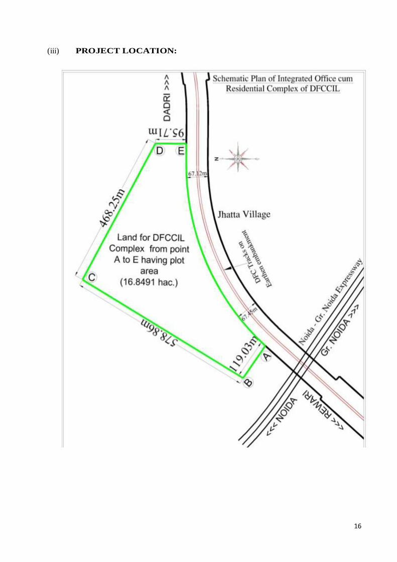
(iii) PROJECT LOCATION:
17
(iv) PROJECT BACKGROUND & OVERVIEW:
1. DFCCIL is in possession of free hold land measuring 16.8491 hectares (approx.
40 Acres) at Noida-Greater Noida Expressway in village Jhatta, Noida. The
schematic site plan is as shown above having exact location, adjacent features
and boundaries of the land. DFCCIL is fully entitled to develop the said land.
The land is almost flat and located in village Jhatta, G.B. Nagar (U.P).
2. On the western & southern side, the site is bounded by Noida-Greater Noida
Expressway & Noida-Gr. Noida Metro Line and on the eastern site it is bounded
by Hindon river, its bund & forest area. The DFCCIL site lies between two
functional Metro Stations Sec145 & Sec-146 Noida of Noida-Greater Noida
metro line.
3. The plot enjoys excellent linkages with other parts of Noida & Greater Noida and
is approachable by Noida-Greater Noida Expressway and is approx. 16 km from
Mahamaya Flyover in Noida.
(v) General Instructions (for only E-Tendering system):
Submission of Online Bids is mandatory for this Notice Inviting Tender. E-Tendering
is a new methodology for conducting Public Procurement in a transparent and
secured manner. Suppliers/Vendors will be the biggest beneficiaries of this new
system of procurement. The E-Tendering portal of Indian Railways can be accessed
on http://www.ireps.gov.in for participation in Dedicated Freight Corridor
Corporation of India (DFCCIL) tenders.
A) ACCESSING/OBTAINING/PURCHASING PROCESS OF TENDER
DOCUMENT:
(i) It is mandatory for all the Tenderers to have class-III digital signature (in the
name of person who will sign the Bid and will submit the online tender and is
authorized to do so) certified from any of the licensed certifying agency (“CA”)
to participate in E-Tendering of DFCCIL [Tenderers can see the list of licensed
CAs from the link www.cca.gov.in].
(ii) To participate in the E-Tender, it is mandatory for the Tenderers to get
themselves registered with the IREPS (www.ireps.gov.in) and to have user ID
& password. Instructions regarding registration are available on
www.ireps.gov.in ˃ Learning Centre ˃ General ˃ User Manual for registration
of new Vendors and Contractors.
(iii) www.ireps.gov.in is the only website for submission of online tender.
Instructions regarding E-Tendering process are available on www.ireps.gov.in
˃ Learning Centre ˃ E-Tender(Works) ˃ User Manual for Contractor.

18
(iv) Tender shall be submitted through online mode only at www.ireps.gov.in.
Tender submitted by any other mode will not be accepted.
(v) All the required documents (legible) as mentioned in Check list S.No. 1 to 15
have to be uploaded along with the offer on www.ireps.gov.in, failing which, the bid may not be considered.
(vi) The Addendum/Corrigendum, if any; shall be hosted on the website
www.ireps.gov.in only.
(vii) The supporting documents for Eligibility Criteria are essentially required to be
uploaded on the website www.ireps.gov.in as bid shall be accepted through
Online mode only.
(viii) Tenderers are required to give Un-Conditional offers. A Conditional Offer is
liable to be rejected. DFCCIL reserves the right to modify, expand, restrict,
cancel, reject and re-float tender without assigning any reasons whatsoever.
(ix) The Tenderers shall closely peruse all the clauses, instructions, terms and
conditions, scope of work, specification etc. as indicated in the Tender
Document before quoting the rates. If the tenderer has any doubt about the
meaning of any portion of the Tender Document or find
discrepancies/omissions in the tender document issued or required clarification,
he shall at once contact the authority inviting the tender for clarification at least
fifteen days before the due date of submission of the tender.
(x) Bid document shall be accompanied by all the documents required to be
submitted as specified in the Tender Document along with all Addendums and
Corrigendum.
(xi) All Bids shall be submitted in accordance with the instructions contained in the
Tender Document (Bid Document). Non-Compliance of any of the instructions
contained in the Tender Document is liable in Bid being rejected.
(xii) After award of contract ot the Successful Contractor, if it is observed that there
is any discrepancy or ambiguity about any terms and conditions mentioned in
the Tender Document, the interpretation of same given by DFCCIL shall be
considered as final and binding.
(xiii) Order of precedence of Documents: In tender/contract, in case of any
difference, contracdiction, discrepancy, with regard to conditions of
tender/contract, specifications, drawings, bill of quantities etc., forming part of
the tender/contract, the following shall be the order of precedence:
a. Letter of Acceptance (LOA)
b. Schedule of items, Rates & Quantities.
c. Special Conditions of Contract.
d. Technical Specifications as given in tender documents.

19
e. Drawings, if any.
f. General Conditions of Contract.
g. Relevant BIS Codes.
For example, if any item is found common in Special Conditions of contract
and General Conditions of Contract then the provision given in Special
Conditions of Contract will prevail over General Conditions of Contract for the
same item.
(xiv) Contractor must fill up all the schedules and furnish all the required
information on e-mode as per the instructions given in various sections of the
Tender Document.
(xv) Submission of a tender by a tenerer implies that he had read all the tender
document including amendments/corrigendum if any, visited the site and made
himself aware of the scope of the work to be done, local conditions and other
factors having any bearing on the execution of the work.
(xvi) DFCCIL reserves all rights to reject any tender including of those tenders who
fail to comply with the instructions without assigning any reason whatsoever
and does not bind itself to accept the lowest or any specific tender. The decision
of DFCCIL in this regard shall be final and binding. Any failure on the part of
the tenderer to observe the prescribed procedure and any attempt to canvass for
the work will prejudice the tenderer’s bid.
(xvii) Tenderers may note that they are liable to be disqualified at any time during
tendering process in case any of the information furnished by them is not found
to be true. Earnest Money Depost (EMD) of such tenderer shall be forfeited.
The decision of the DFCCIL in this regard shall be final and binding.
(xviii) Evaluation of tenders will be made on the basis of fulfilment of Eligibility
Criteria mentioned in the Bid Document. However, DFCCIL reserves the right
to seek any clarification from the contractor.
B) PREPARATION & SUBMISSION OF TENDER:
a. Documents mentioned at S.No. 1 to 16 of the Check list
[Technical Bid (Packet-A)] should be scanned and uploaded
during bid submission as per detailed instructions for submission
of bid available on website www.ireps.gov.in.
b. Documents mentioned at S.No. 17 & 18 of the Check list
[Technical Bid (Packet-A)] should be uploaded during bid
submission as per detailed instructions for submission of bid
available on website www.ireps.gov.in.
c. For Document No. 19 of the Check list [Financial Bid (Packet-B)],
20
Financial Bid to be filled and submitted on www.ireps.gov.in by
following the steps available on the website.
C) Modification/ Substitution/ Withdrawal of bids:
(i) Once bid is submitted, the tenderer will not be allowed to withdraw the offer.
(ii) The tenderer can however submit revised bid till closing time of tender. In case
of revising the bid, the revised bid will supersede the earlier bid. Only the last
bid submitted by the tenderer shall be considered for evaluation and earlier bids
shall be ignored.
D) PRE-BID MEETING/ AMENDMENT IN TENDER:
Pre –Bid meeting is not scheduled for the tender. At any time before the submission
of tender, DFCCIL may modify/amend the bid document and extend the last date of
submission/opening of the tender by issuing a corrigendum/addendum as per IREPS
guidelines.
Any Corrigendum/Addendum thus issued shall form part of tender document and
shall be posted only on www.ireps.gov.in and the Bidders are thus advised to update
their information by using said website www.ireps.gov.in. To give the Bidders
reasonable time to take an amendment into account in their bids and on account of
any other reasonable circumstances, DFCCIL may at its discretion, extend the
deadline for the submission/opening of the tender.
E) OPENING AND EVALUATION OF BIDS:
(i) Opening of Bids will be done through online process at www.ireps.gov.in.
(ii) E-Tender shall be opened Online at the address given below at the time and
date as specified in Part-1 (Notice Inviting Tender) in the presence of Tenderers
or their authorized representatives, if they choose to attend the Online Tender
Opening.
Address for Online Opening of Tender:
Dedicated Freight Corridor Corporation of India Ltd./Noida Unit,
Sector 145, Noida.
(iii) For participating in the tender, the authorized signatory holding Power of
Attorney shall be the Digital Signatory.
(iv) The Authority shall Open Bid Documents received in electronic form online on
the date and time as specified in the NIT.

21
(v) The Authority will subsequently examine and evaluate the Technical Bids in
accordance with the provisions set out in the BID DOCUMENTS.
(vi) The Financial Bids will be opened only of the technically qualified Bidders
(after evaluation of Technical Bids) & the date of opening of Financial Bids
will be notified later on.
DISCLAIMER
The Bidder must read all the instructions in the BID DOCUMENTS and ensure to
complete the tender submission process by due date and time as www.ireps.gov.in
will not accept any online tender after tender closing date and time as specified in the
NIT.
The agency may visit the site on any working day to assess the site conditions and
scope of work before submitting their offer.
(vii) Scope of Work
Chief General Manager, Dedicated Freight Corridor Corporation of India
Limited, Sector 145, Noida-201310 India, hereinafter referred to as 'DFCCIL’
is inviting E-Tenders from Firms/ Companies/Joint Ventures having requisite
experience and financial capacity for execution of the following work:-
“Supply, Erection, Testing and Commissioning of 33 kV Sub-stations, DG Set and
Related Works for DFCCIL Integrated Office Cum Residential Complex at Sec-
145, Noida”.
Two nos 33/0.4 KV Substations are included in the proposed work. The brief scope of
work is given below:-
S.No. Description of Work
1 Supply & Installation of 33 kV HT Panel with One VCB
2 Supply & Installation of 33 kV HT Panel with One Incomer and Three
Outgoing VCBs
3 Supply & Installation of 33 kV/415 V Transformers
4 Supply & Installation of LT Panels
5 Supply & Installation of APFC Panel with Capacitors
6 Supply & Installation of Ornamental Street Light Poles( 7M/9M) with
LED Luminaries
7 Supply & Installation of High Mast with LED Luminaries
8 Supply & Laying of HT & LT Cables
9 Supply and installation of Diesel Generator Sets
10 Supply and installation of Diesel storage tank and pipeline
11 Building/Civil work of the two Sub-Stations, Meter Room & HSD Tank
22
Foundation
Some reference drawings for guidance have been enclosed with the tender document.
(viii) Cost of the work: The estimated cost of the tendered work is 18,27,43,008/-
(Rupees Eighteen Crore Tweenty Seven Lakh Forty Three Thousand Eight Only)
(Including GST @18%)
(ix) The tenderer(s) shall be governed by General Conditions of Contract (GCC),
Preamble and General Instructions to Tenderers (ITT) and Special Conditions of
Contract (SCC). Wherever, there is a conflict in any condition between GCC and
Special Conditions of Contract mentioned in the tender documents, the condition
mentioned in Special Conditions of Contract will prevail. However, Engineer's
decision in this connection shall be final and binding.
1.3.2 Form of Tender
The Tender bid shall have to be submitted in Two Packet System through IREPS i.e.
www.ireps.gov.in.
"Packet-A”
Eligibility/Qualifiying Element of the tender bid along with other requisite documents
as mentioned in Techinical bid (Packet-A) of Check List, Part-I, Chapter-I of the
Tender Document.
"Packet-B”
Price Element of tender bid with percentage above/below/at par on the Schedule of
Prices duly filled in as mentioned in Financial bid (Packet-B) of Check List, Part-
I,Chapter-I of the Tender Document.
The technical bid (Packet-A) shall be opened on the date of tender opening and the
detailed scrutiny of Technical bid shall be carried out. The “Financial Bid” (Packet-B)
shall be opened only of those tenderers who qualify in “Technical Bid”. The detailed
procedure for tender opening and processing is defined in Para 1.3.5.
1.3.3 Tender Document
The tender document consists of following four parts:
PART/CHAPTERS DESCRIPTION
PART – I
Chapter I Check list of documents to be uploaded/submitted in the E-
Tender
23
Chapter II Notice Inviting E-Tender
Chapter III Preamble and General Instructions to Tenderers
Chapter IV General Conditions of Contract
Chapter V Special Conditions of Contract
PART – II Technical Specifications
Chapter I Technical Spefications for Substation
Chapter II Technical Spefications for External Lighting
Chapter III Technical Specification for DG Set, HSD Tank and Piping
Chapter-IV Technical Spefications for Civil
Chapter V Make List
PART – III
Chapter I Milestones and Time Schedule
Chapter II Tender Forms
PART – IV Drawings
1.3.4 Sale & Submission of Tender Document:
1.3.4.1 Cost of Tender document: -
Tender document is available on www.ireps.gov.in and the same can be downloaded
and used as tender documents for submitting the offer. The cost of tender document as
prescribed in the NIT shall be deposited online through payment gateway of
www.ireps.gov.in by the tenderer.
1.3.4.2 Earnest Money Deposit: -
(a) The tenderer shall be required to deposit earnest money with the tender for the due
performance with the stipulation to keep the offer open till such date as specified
in the tender, under the conditions of tender.
(i) Any firm recognized by Department of Industrial Policy and Promtiion (DIPP) as
‘Startups’ shall be exempted from payment of earnest money deposit detailed
above.
(ii) 100% Govt. owned PSUs shall be exempt from payment of earnest money
deposit detailed above.
(iii)Labour Cooperative Societies shall deposit only 50% of above earnest money
deposit detailed above.
(b) The tenderer must deposit the amount of Earnest Money for the amount
prescribed, online through the payment gateway on www.ireps.gov.in as
mentioned in the NIT.
(c) Tenderers received without Earnest Money in full in the manner prescribed above
shall be summarily rejected.
(d) The earnest money shall remain deposited with the DFCCIL for the period of
validity of the offer prescribed in this tender i.e. 120 days from the date of
24
opening of tender. If the validity of the offer is extended, the validity of earnest
money should also be extended failing which, the offer, after the expiry of the
aforesaid period, may not be considered by DFCCIL.
(e) It is understood that the tender documents have been sold/issued to the
tenderer(s) and the tenderer(s) is/are permitted to tender in consideration of
stipulation on his/their part, that after submitting his/their tender (subject to
the period being extended further), he will not resile from his offer or modify the
terms and conditions, thereof in a manner not acceptable to DFCCIL. Should the
tenderer fail to observe or comply with the foregoing stipulation, the amount
deposited as earnest money for the due performance of the above stipulation,
shall be forfeited by DFCCIL.
(f) The Earnest Money Deposit of the successful Tenderer, will be retained towards
part of Security Deposit for the due and faithfull fulfillment of the contract in
terms of caluse 16 of the General Conditions of the contract.
(g) The earnest money of the unsuccessful tenderer(s) shall, save as herein before
provided, be returned to the unsuccessful tenderer(s) within a reasonable time, but
the DFCCIL shall not be responsible for any loss or depreciation that may happen
thereto while in their possession, nor be liable to pay interest thereon.
(h) DFCCIL reserves the rights of forfeiture of Earnest Money Deposit (EMD) in
case of successful tenderers if: -
i. Does not execute the Contract Agreement within stipulated time: or
ii. Does not submit Performance Security in the form of Bank Guarantee of the
requisite value within stipulated time: or
iii. Does not commence the work after receipt of Letter of Acceptance or date as
specified in the Letter Acceptance.
iv. Withdraws the offer during the period of validity/extended validity.
v. When any of the information furnished by the tenderer not found true.
vi. If the work is terminated at any stage as per terms and conditions of the contract.
(i) In case contractor submit Term Deposit Receipt/Bank Guarantee bond towards
full Security Deposit, the DFCCIL shall return the earnest money so retained to
the contractor.
1.3.4.3 Clause applicable for tender documents downloaded from Internet
Tenderer/s are free to download tender documents at their own cost, for the purpose of
perusal as well as for using the same as tender document for submitting their offer.
Master copy of the tender document will be available in the office of Chief General
Manager, Sector 145, Noida, U.P., India.

25
After award of the work, an agreement will be drawn up. The agreement shall be
prepared based on the master copy available in the office of Chief General Manager,
Dedicated Freight Corridor Corporation of India Limited, Sector 145, Noida- 201310,
U.P., India and not based on the tender documents submitted by the Tenderer. In case of
any discrepancy between the tender documents downloaded from the internet and the
master copy, later shall prevail and will be binding on the Tenderers. No claim on this
account shall be entertained.
1.3.4.4 Complete tender documents must be submitted online duly completed in all respect on
www.ireps.gov.in upto date and time mentioned in NIT. The “Packet-A
(TECHNICAL BID)” will be opened at the time and date mentioned in NIT and read
out in the presence of such tenderer(s) as is/are present. In case the intended date for
opening of tenders is declared a holiday, the tenders will be opened on the next working
day at the same time. Any modified date and time for submission of tenders shall be
uploaded on www.ireps.gov.in. The detail procedure of tender opening will be as per
para- 1.3.5.
1.3.4.5 The rates should be quoted in figures as well as in words. If there is variation between
rates quoted in figures and in words, the rate quoted in ‘words’ shall be taken as correct.
If more than one or improper rates are tendered for the same item, the tender is liable to
be rejected. However guidelines given on www.ireps.gov.in shall prevail.
1.3.4.6 Each page of the tender papers is to be signed by the tenderers or such person/s on
his/their behalf who is/are legally authorized to sign for him/them. However guidelines
given on www.ireps.gov.in shall prevail.
1.3.4.7 Tenders containing erasures and/or alteration of the tender documents are liable to be
rejected.
1.3.4.8 Care in Submission of Tenders–
(a) (i) Before submitting a tender, the tenderer will be deemed to have satisfied himself by
actual inspection of the site and locality of the works, that all conditions liable to be
encountered during the execution of the works are taken into account with that the rates
he enters in the tender forms are adequate and all-inclusive to accord with the provisions
in Clause 37 of the Standard General Conditions of Contract for the completion of works
to the entire satisfaction of the Engineer/DFCCIL.
(a)(ii) Tenderers will examine the various provisions of the Central Goods and Services Tax
Act, 2017(CGST)/Integrated Goods and Services Tax Act, 2017(IGST)/Union Territory
Goods and Services Tax Act, 2017(UTGST)/respective state’s State Goods and Services
Tax Act (SGST) also, as notified by Central/State Govt & as amended from time to time
and applicable taxes before bidding. Tenders will ensure that full benefit of Input Tax
(ITC) likely to be availed by them is duly considered while quoting rates.
(a)(iii) The successful tenderer who is liable to be registered under CGST/IGST/UTGST/SGST
Act shall submit GSTIN along with other details required under
26
CGST/IGST/UTGST/SGST Act to Railway/DFCCIL immediately after the award of
contract, without which no payment shall be released to the contractor. The contractor
shall be responsible for deposition of applicable GST to the concerned authority.
(a)(iv) In case, the successful tenderer is not liable to be registered under
CGST/IGST/UTGST/SGST Act, the railway/DFCCIL shall deduct the applicable GST
from his/their bills under reverse charge mechanism (RCM) and deposit the same to the
concerned authority.
(b) When work is tendered for by a firm or company the tender shall be signed by the
individual legally authorized to enter into commitments on their behalf.
(c) The Railway/DFCCIL will not be bound by any power of attorney granted by the
tenderer or by changes in the composition of the firm made subsequent to the execution
of the contract. It may however, recongnize such power of attorney and changes after
obtaining proper legal advice, the cost of which will be chargeable to the contractor.
1.3.5 Opening of Tender: Two packet system of tendering shall be adopted in this tender
(a) Tender will be opened at the scheduled date and time mentioned in NIT, in the
office of Chief General Manager/Noida, Dedicated Freight Corridor
Corporation of India Limited, Sector 145, Noida-201310, U.P, India in the
presence of the tenderers or their representatives as may be present at the
prescribed date and time.
(b) After the opening of “TECHNICAL BID” (Packet-A) of all the eligible
tenderers, these bids shall be scrutinized and analysed. DFCCIL reserve the right
to seek clarifications on the submitted documents from the tenderers. The names
of the tenderers whose bid are considered complete and meet eligibility criteria
shall be shortlisted.
(c) The FINANCIAL BID (Packet–B) shall be opened on a subsequent date and
time duly notified well in advance. The Financial bids of only those tenderers
shall be opened who are shortlisted after scrutiny of their Technical bid. The
Financial bid of the tenderers who do not qualify during scrutiny of Technical bid
shall not be opened. The time and date of opening of Financial Bid shall be
advised to qualified tenderers well in advance on www.ireps.gov.in only.
1.3.6 Validity of Tender: -
Tenderer shall keep his offer open for a minimum period of 120 days from the date of
opening of the tender or as mentioned in the Tender Notice.
1.3.7 Execution of Contract Agreement: -
The Tenderer whose tender is accepted shall be required to appear in person at the
office of Chief General Manager, Dedicated Freight Corridor Corporation of India
Limited, Sector-145, Noida-201310, as the case may be, or if tenderer is a firm or
corporation, a duly authorized representative shall appear and execute the contract
agreement within 07 days of notice from DFCCIL that the contract agreement
27
is ready. The Contract Agreement shall be entered into by DFCCIL only after
submission of valid Performance Guarantee by the Contractor. Failure to do so shall
constitute a breach of the agreement affected by the acceptance of the tender. In such
cases, the DFCCIL may determine that such tenderer has abandoned the contract and
there upon his tender and acceptance thereof shall be treated as cancelled and the
DFCCIL shall be entitled to forefeit the full amount of the earnest money and other
dues payable to the Contractor under this contract. The failed Contractor shall be
debarred from participating in the re-tender for that work.
1.3.8 Security Deposit on Acceptance of Tender:
The security deposit/rate of recovery/mode of recovery on acceptance of tender shall be
as per the Para 16. (1) to 16. (3) of General Conditions of Contract (GCC).
1.3.9 Tenderer’s Address
The tenderer should state in the tender his postal/electronic e-mail address(s) legibly and
clearly. Any communication sent in time, to the tenderer by post at his said address shall
be deemed to have reached the tenderer duly and in time. Important documents should
be sent by registered post.
1.3.10 Right of DFCCIL to Deal with Tenders
(a) The DFCCIL reserves the right of not to invite tenders for any of DFCCIL work or
works or to invite open or limited tenders and when tenders are called to accept a tender
in whole or in part or to reject any tender or all tenders without assigning reasons for
any such action.
(b) The authority for the acceptance of the tender will rest with the DFCCIL. It shall not be
obligatory on the said authority to accept the lowest tender or any other tender and no
tenderer(s) shall demand any explanation for the cause of rejection of his/their tender
nor the DFCCIL undertake to assign reasons for declining to consider or reject any
particular tender or tenders.
(c) If the tenderer(s) deliberately gives / give wrong information in his / their tender or
creates / create circumstances for the acceptance of his / their tender, the Railway
reserves the right to reject such tender at any stage.
(d) If the tenderer(s) expire(s) after the submission of his / their tender or after the
acceptance of his /their offer, the Railway shall deem such tender cancelled. If a partner
of a firm expires after the submission of their tender or after the acceptance of their
tender, the Railway shall deem such tender as cancelled, unless the firm retains its
character.
(e ) Provisions of Make in India Policy 2017 issued by Govt. of India, as amended from
time to time, shall be followed for consideration of tenders.
28
1.3.11 Eligibility Criteria
1.3.11.1 Technical Eligibility Criteria
The tenderer must have successfully completed any of the following during last 07
(seven) years, ending last day of month previous to the one in which tender is invited:
Three similar works each costing not less than the amount equal to 30% of
advertised value of tender, or
Two similar works each costing not less than the amount equal to 40% of
advertised value of tender, or
One similar work costing not less than the amount equal to 60% of advertised
value of tender.
Similar Work:
Work of Supply, Installation, Testing and Commissioning of 33 KV or above Sub-
Station shall be considered as Similar Work for the tendered work. Upgradation/
Augmentation of existing Sub Station shall not be considered as Similar Work.
Note for Item 1.3.11.1:
1. Work experience certificate from private individual shall not be considered. However, in
addition to work experience certificates issued by any Govt. Organisation, work
experience certificate issued by Public listed company having average annual turnover
of Rs 500 crore and above in last 3 financial years excluding the current financial year,
listed on National Stock Exchange or Bombay Stock Exchange, incorporated/registered
at least 5 years prior to the date of opening of tender, shall also be considered provided
the work experience certificate has been issued by a person authorized by the Public
listed company to issue such certificates.
In case tenderer submits works, experience certificate issued by Public listed company,
the tenderer shall also submit along with work experience certificate, the relevant copy
of work order, bill of quantitites, bill wise details of payment received duly certified by
Chartered Accountant, TDS certificates for all payments received and copy of final/last
bill paid by company in support of above work experience certificate.
2. Value of complete work done by a member in an earlier JV Firm shall be reckoned only
to the extent of the concerned member’s share in that JV firm for the purpose of
satisfying his or her compliance to the above-mentioned technical eligibility criteria in
the tender under consideration.
3. In case the tenderer (s) is a partnership firm, the work experience shall be in the name of
partnership firm only.
29
1.3.11.2 Financial Eligibility Criteria
The tenderer must have received contractual payments in the previous three financial
years and the current financial year upto the date of inviting of tender, at least 150% of
the advertised value of the Tender. The tenderers shall submit Certificates to this effect
which may be an attested certificate from the concerned department/client or Audited
Balance Sheet duly certified by the Chartered Accountant/Certificate from Chartered
Accountant duly supported by Audited Balance sheets.
Note for Item 1.3.11.2:
1. Contractual payments received by a Member in an earlier JV firm shall be reckoned
only to extent to the concerned member’s share in that JV Firm for the purpose of
satisfying compliance of the above-mentioned financial eligibility criteria in tender
under considerations.
2. In case the tenderer/s is a partnership firm, the turnover etc shall be in the name of
partnership firm only.
3. Client certificate from other than Govt. Organization should be duly supported by
Form 16A/26AS generated through TRACES of Income Tax Department of India.
1.3.11.3 Credentials if submitted in foreign currency shall be converted into Indian currency i.e.,
Indian Rupee as under:
The conversion rate of US Dollars into Rupees shall be the daily representative
exchange rates published by the Reserve Bank of India for the relevant date. Where,
relevant date shall be as on the last day of month previous to the one in which tender is
invited. In case of any other currency, the same shall first be converted to US Dollars as
on the last day of month previous to the one in which tender is invited, and the amount
so derived in US Dollars shall be converted into Rupees at the aforesaid rate. The
conversion rate of such currencies shall be the daily representative exchange rates
published by the International Monetary Fund for the relevant date.
1.3.11.4 Explanation for clause 1.3.11 including clause 1.3.11.1 to 1.3.11.3 - Eligibility Criteria:
1. In case a work is started prior to 07 (seven) years, ending last day of month previous to
the one in which tender is invited, but completed in last 07 (seven) years, ending last day
of month previous to the one in which tender is invited, the completed work shall be
considered for fulfillment of credentials.
2. If a work is physically completed and completion certificate to this extent is issued by
the concerned organization but final bill is pending, such work shall be considered for
fulfillment of credentials.
30
3. If a part or a component of work is completed but the overall scope of contract is not
completed, this work shall not be considered for fulfillment of technical credentials even
if the cost of part completed work/component is more than required for fulfillment of
credentials.
4. In case a work is considered similar in nature for fulfillment of technical
credentials, the overall cost of that work including PVC amount if any shall be
considered and no separate evaluation for each component of that work shall be
made to decide eligibility.
5. The value of final bill including PVC amount-if paid, or otherwise in case final bill is
pending the contract cost in last approved variation statement plus PVC amount paid or
cumulative amount paid up to last on-account bill including PVC amount and statutory
deductions whichever is less, shall be considered as the completion cost of work.
6. In case of newly formed partnership firm, the credentials of individual partners from
previous propriety firm(s) or dissolved previous partnership firm(s) or split previous
partnership firm(s), shall be considered only to the extent of their share in previous
entity on the date of dissolution / split and their share in newly formed partnership firm.
For example, a partner A had 30% share in previous entity and his share in present
partnership firm is 20%. In the present tender under consideration, the credentials of
partner A will be considered to the extent of 0.3*0.2*value of the work done in the
previous entity. For this purpose, the tenderer shall submit along with his bid all the
relevant documents which include copy of previous partnership deed(s), dissolution
deed(s) and proof of surrender of PAN No.(s) in case of dissolution of partnership
firm(s) etc.
7. In case of existing partnership firm, if any one or more partners quit the partnership firm,
the credentials of remaining partnership firm shall be re-worked out i.e., the quitting
partner(s) shall take away his credentials to the extent of his share on the date of quitting
the partnership firm (e.g. in a partnership firm of partners A, B & C having share 30%,
30% & 40% respectively and credentials of Rs 10 crore; in case partner C quits the firm,
the credentials of this partnership firm shall remain as Rs 6 crore). For this purpose, the
tenderer shall submit along with his bid all the relevant documents which include copy
of previous partnership deed(s), dissolution deed(s) and proof of surrender of PAN
No.(s) in case of dissolution of partnership firm(s) etc.
8. In case of existing partnership firm if any other partner(s) joins the firm, the credentials
of partnership firm shall get enhanced to the extent of credentials of newly added
partner(s) on the same principles as mentioned in item 6 above. For this purpose, the
tenderer shall submit along with his bid all the relevant documents which include copy
of previous partnership deeds, dissolution/splitting deeds and proof of surrender of PAN
No.(s) in case of dissolution of partnership firm etc.
9. Any partner in a partnership firm cannot use or claim his credentials in any other firm
without leaving the partnership firm i.e., In a partnership firm of A&B partners, A or B
partner cannot use credentials of partnership firm of A&B partners in any other
partnership firm or propriety firm without leaving partnership firm of A&B partners.
10. In case a partner in a partnership firm is replaced due to succession as per succession
law, the proportion of credentials of the previous partner will be passed on to the
successor.
11. If the percentage share among partners of a partnership firm is changed, but the partners
remain the same, the credentials of the firm before such modification in the share will
31
continue to be considered for the firm as it is without any change in their value. Further,
in case a partner of partnership firm retires without taking away any credentials from the
firm, the credentials of partnership firm shall remain the same as it is without any change
in their value.
12. In a partnership firm “AB” of A&B partners, in case A also works as propriety firm “P”
or partner in some other partnership firm “AX”, credentials of A in propriety firm “P” or
in other partnership firm “AX” earned after the date of becoming a partner of the firm
AB shall not be added in partnership firm AB.
13. In case a tenderer is LLP, the credentials of tenderer shall be worked out on above lines
similar to a partnership firm.
14. In case company A is merged with company B, then company B would get the
credentials of company A also.
1.3.11.5 Credentials of Tenderer:
The tenderer shall provide satisfactory evidence in support of their technical and
financial eligibility, which are acceptable to DFCCIL, alongwith the tenderer:
(a) For Technical eligibility criteria, the details will be submitted in Form No.2A/2AA
along with supporting documents.
(b) For Financial eligibility criteria, the details will be submitted in “Form No.2B”
alongwith supporting documents.
(d) The tenderer shall submit the completion certificates/certified completion certificates
from the client(s) or Photostat of original certificates of client. These certificates should
indicate the details of works carried out and successful commissioning of similar type of
work executed by the tenderer. Completion certificate from Govt. organisation/Semi
Govt. organizations/PSUs/Public Listed Company will only be accepted. The certificate
from Private individual/Private Company for whom such works are executed shall not
be accepted. In case, the work is executed for Public Listed Company, copy of work
order, bill of Quantity, Billwise details of payment received duly certified by Chareted
Accountant, TDS certificates for all payments received and copy of final/last bill paid by
Company in support of above work experience certificate shall be submitted.
(e) Tenderer shall submit a statement of contractual payments received during last three
financial years and current financial year on the prescribed Performa as per “Form No.
2B”. The details shall be based on the form16-A issued by the employer i.e. the
certificate of deduction of tax at source as per Income Tax Act, 1961 and Form-26AS
issued by Income Tax Department. The photocopies of Form 16-A/Form-26AS shall
been closed or a certificate from auditor or audited balance sheet certified by Chartered
Accountant clearly indicating the contractual amount received. DFCCIL may invite the
Tenderer for offline/online verification of Form-16A & Form-26AS.

32
(f) The tenderers shall submit a copy of certificate stating that they are not liable to be
disqualified and all their statements/documents submitted alongwith bid are true and
factual. Standard format of the certificate to be submitted by the bidder is enclosed as
“Form-1B”. Non submission of “Form-1B” by the bidder shall result in summarily
rejection of his/their bid. It shall be mandatorily incumbent upon the tenderer to identify,
state and submit the supporting documents by which they/he are/is qualifying the
Qualifying Criteria mentioned in the Tender Document.
(g) The Railway/DFCCIL reserves the right to verify all statements, information and
documents submitted by the bidder in his tender offer, and the bidder shall, when so
required by the Railway/DFCCIL, make available all such information, evidence and
documents as may be necessary for such verification. Any such verification or lack of
such verification, by the Railway/DFCCIL shall not relieve the bidder of its obligations
or liabilities hereunder nor will it affect any rights of the Railway/DFCCIL thereunder.
(h) (i) In case of any information submitted by tenderer is found to be false forged or
incorrect at any time during process for evaluation of tenders, it shall lead to forfeiture
of the tender Earnest Money Deposit besides banning of business for a period of upto
five years.
(ii) In case of any information submitted by tenderer is found to be false forged or
incorrect after the award of contract, the contract shall be terminated. Earnest Money
Deposit (EMD), Performance Guarantee and Security Deposit available with the
railway shall be forfeited. In addition, other dues of the contractor, if any, under this
contract shall be forfeited and agency shall be banned for doing business for a period
of upto five years.
(i) The tenderer shall be considered disqualified/ineligible if:
(a) The Tenderer or any of its partners and/or subcontractors included in the tender has
been banned for business with Ministry of Railways/DFCCIL along with any of its
attached and subordinate offices through an order issued by Ministry of Railways as
per list available on Web site (http://www.indianrailways.gov.in/railwayboard) of
Railway Board pertaining to banning of Business, with the banning being valid as on
the date of submission of the Tender.
(b) The Tenderer or any of its partners has suffered bankruptcy/insolvency or it is in the
process of winding-up or there is a case of insolvency pending before any Court on
the deadline of submission of application.
1.3.12 Non-compliance with any of the conditions set forth therein above is liable to result in the
tender being rejected.
1.3.13 Execution of Contract Documents:
33
The successful Tenderer(s) shall be required to execute an agreement with the DFCCIL
for carrying out the work according to Standard General Conditions of Contract, Special
Conditions/Specifications annexed to the tender and Standard Specifications (Works and
Materials) of CPWD/DFCCIL as amended/corrected upto latest correction slips,
mentioned in tender form.
1.3.14 Documents to be submitted alongwith Tender (Constitution of the Firm,
Partnership Deeds, Power of Attorney etc): -
(i) The tenderer shall clearly specify whether the tender is submitted on his own
(Proprietary Firm) or on behalf of a Partnership Firm / Company / Joint Venture (JV) /
Registered Society / Registered Trust/ HUF etc. The tenderer(s) shall enclose the
attested copies of the constitution of their concern, and copy of PAN Card along with
their tender. Tender Documents in such cases are to be signed by such persons as may be
legally competent to sign them on behalf of the firm, company, association, trust or
society, as the case may be.
(ii) Following documents shall be submitted by the tenderer:
(a) Sole Proprietorship Firm:
(i) An undertaking that he is not blacklisted or debarred by Railways/DFCCIL or any
other Ministry/ Department of Govt. of India from participation in tender on the date
of opening of bids, either in individual capacity or as a member of the partnership
firm or JV in which he was/ is a partner/member. Concealment / wrong information
in regard to above shall make the contract liable for determination under Clause 62 of
the General Conditions of Contract.
(ii) All other documents in terms of explanatory notes in clause 1.3.11.1 to 1.3.11.5
above.
(b) HUF:
(i) A copy of notarized affidavit on Stamp Paper declaring that he who is submitting the
tender on behalf of HUF is in the position of ‘Karta’ of Hindu Undivided Family
(HUF) and he has the authority, power and consent given by other members to act on
behalf of HUF.
(ii) An undertaking that the HUF is not blacklisted or debarred by Railways/DFCCIL or
any other Ministry / Department of Govt. of India from participation in tender on the
date of opening of bids, either in individual capacity or as a member of the
partnership firm or JV in which HUF was/ is a partner/member. Concealment / wrong
information in regard to above shall make the contract liable for determination under
Clause 62 of the General Conditions of Contract.
(iii) All other documents in terms of explanatory notes in clause 1.3.11.1 to 1.3.11.5
above.
34
(c) Partnership Firm:
(i) The tenderer shall submit documents as mentioned in Clause 1.3.18 of the Part-I,
Chapter-III of the Tender Document.
(d) Joint Venture (JV): The tenderer shall submit documents as mentioned in Clause
1.3.17 of the Part-I, Chapter-III of the Tender Document.
(e) Company registered under Companies Act 2013:
(i) The copies of MOA (Memorandum of Association) / AOA (Articles of Association) of
the company
(ii) A copy of Certificate of Incorporation
(iii) A copy of Authorization/Power of Attorney issued by the Company (backed by the
resolution of Board of Directors) in favour of the individual to sign the tender on behalf
of the company and create liability against the company.
(iv) An undertaking that the Company is not blacklisted or debarred by Railways/DFCCIL or
any other Ministry / Department of Govt. of India from participation in tender on the
date of opening of bids, either in individual capacity or as a member of the partnership
firm or JV in which the Company was / is a partner/member. Concealment / wrong
information in regard to above shall make the contract liable for determination under
Clause 62 of the General Conditions of Contract.
(v) All other documents in terms of explanatory notes in clause 1.3.11.1 to 1.3.11.5 above.
(f) LLP (Limited Liability Partnership): If the tender is submitted on behalf of a LLP
registered under LLP Act-2008, the tenderer shall submit along with the tender:
(i) A copy of LLP Agreement
(ii) A copy of Certificate of Incorporation
(iii) A copy of Power of Attorney/Authorization issued by the LLP in favour of the
individual to sign the tender on behalf of the LLP and create liability against the LLP.
(iv) An undertaking that the LLP is not blacklisted or debarred by Railways or any other
Ministry / Department of Govt. of India from participation in tender on the date of
opening of bids, either in individual capacity or as a member of JV in which the LLP
was / is a member. Concealment / wrong information in regard to above shall make the
contract liable for determination under Clause 62 of the General Conditions of Contract.
(v) All other documents in terms of explanatory notes in clause 1.3.11.1 to 1.3.11.5 above.
(g) Registered Society & Registered Trust: The tenderer shall submit:
(i) A copy of the Certificate of Registration
(ii) A copy of Deed of Formation
(iii) A copy of Power of Attorney in favour of the individual to sign the tender
documents and create liability against the Society/Trust.
(iv) All other documents in terms of explanatory notes in clause 1.3.11.1 to 1.3.11.5
above.
(v) If it is NOT mentioned in the submitted tender that tender is being submitted on
behalf of a Sole Proprietorship firm/ Partnership firm/ Joint Venture/ Registered
35
Company etc., then the tender shall be treated as having been submitted by the
individual who has signed the tender.
(vi) After opening of the tender, any document pertaining to the constitution of Sole
Proprietorship Firm / Partnership Firm/ Registered Company/ Registered Trust /
Registered Society / HUF etc. shall be neither asked nor considered, if submitted.
Further, no suo moto cognizance of any document available in public domain (i.e.,
on internet etc.) or in Railway’s/DFCCIL’s record/office files etc. will be taken for
consideration of the tender, if no such mention is available in tender offer submitted.
(vii) A tender from JV/ Partnership firm etc. shall be considered only where permissible
as per the tender conditions.
(viii) The Railway/DFCCIL will not be bound by any change in the composition of the
firm made subsequent to the submission of tender. Railway/DFCCIL may, however,
recognize such power of attorney and changes after obtaining proper legal advice,
the cost of which will be chargeable to the Contractor.
1.3.15 The tenderer whether sole proprietor/ a company or a partnership firm /joint venture
(JV)/registered society/ registered trust/HUF etc if they want to act through agent or
individual partner(s), should submit along with the tender, a copy of power of attorney
duly stamped and authenticated by a Notary Public or by Magistrate in favour of the
specific person whether he/they be partner(s) of the firm or any other person specifically
authorizing him/them to submit the tender, sign the agreement, receive money, co-
ordinate measurements through contractor’s authorized engineer, witness measurements,
sign measurement books, compromise, settle, relinquish any claim(s) preferred by the
firm and sign "No Claim Certificate" and refer all or any disputes to arbitration. The
above power of attorney shall be submitted even if such specific person is authorized for
above purposes through partnership deed/ Memorandum of Understanding/ Article of
Association or such other document, failing which tender is liable to be rejected.
1.3.16 Employment/Partnership etc. of Retired Railway Employees:
(a) Should a tenderer
i) be a retired Engineer of the gazetted rank or any other gazetted officer working before
his retirement, whether in the executive or administrative capacity or whether holding
a pensionable post or not, in the Engineering or any other department of any of the
railways/DFCCIL owned and administered by the President of India for the time
being, OR
ii) being partnership firm / joint venture (JV) / registered society / registered trust etc
have as one of its partners a retired Engineer of the gazetted rank or any other
gazetted officer working before his retirement, OR
iii) being an incorporated company have any such retired Engineer of the gazetted rank or
any other gazetted officer working before his retirement as one of its directors
AND
36
in case where such Engineer or officer had not retired from government service at least
1 year prior to the date of submission of the tender
THEN
the tenderer will give full information as to the date of retirement of such Engineer or
gazetted officer from the said service and as to whether permission for taking such
contract, or if the Contractor be a partnership firm or an incorporated company, to
become a partner or director as the case may be, has been obtained by the tenderer or
the Engineer or officer, as the case may be from the President of India or any officer,
duly authorized by him in this behalf, shall be clearly stated in writing at the time of
submitting the tender.
b) In case, upon successful award of contract, should a tenderer depute for execution of the
works under or to deal matters related with this contract, any retired Engineer of gazette
rank or retired gazetted officer working before his retirement in the Engineering or any
other department of any of the railways/DFCCIL owned and administered by the
President of India for the time being, and now in his employment, then the tenderer will
ensure that retired Engineer or retired gazetted officer had retired from government
service at least 1 year prior to the date of his employment with tenderer and in case he
had retired from service within a year then he possesses the requisite permission from
the President of India or any officer, duly authorized by him in this behalf, to get
associated with the tenderer.
c) Should a tenderer or Contractor being an individual, have member(s) of his family or in
the case of partnership firm/ company / joint venture (JV) / registered society / registered
trust etc. one or more of his partner(s)/shareholder(s) or member(s) of the family of
partner(s)/shareholder(s) having share of more than 1% in the tendering entity employed
in gazetted capacity in the Engineering or any other department of the railway/DFCCIL,
then the tenderer at the time of submission of tender, will inform the authority inviting
tenders the details of such persons.
Note: - If information as required as per 1.3.16 (a), (b), (c) above has not been furnished, contract
is liable to be dealt in accordance with provision of clause 62 of Standard General
Condition of contract.
1.3.17 JOINT VENTURE (JV) IN WORKS TENDERS
Participation of Joint Venture (JV) in Works Tender: This Clause shall be applicable for
works tenders wherein tender documents provide for the same.
1.3.17.1 Separate identity/name shall be given to the Joint Venture.
1.3.17.2 Number of members in a JV shall not be more than three, if the work involves only one
department (say Civil or S&T or Electrical or Mechanical) and shall not be more than
five, if the work involves more than one Department. One of the members of the JV
shall be its Lead Member who shall have a majority (at least 51%) share of interest in
37
the JV. The other members shall have a share of not less than 20% each in case of JV
with upto three members and not less than 10% each in case of JV with more than three
members. In case of JV with foreign member(s), the Lead Member has to be an Indian
firm/company with a minimum share of 51%.
1.3.17.3 A member of JV shall not be permitted to participate either in individual capacity or as a
member of another JV in the same tender.
1.3.17.4 The tender form shall be purchased and submitted only in the name of the JV and not in
the name of any constituent member. The tender form can however be submitted by JV
or any of its constituent member or any person authorized by JV through Power of
Attorney to submit tender.
1.3.17.5 Earnest Money Deposit (EMD) shall be deposited by JV or authorized person of JV
through e-payment gateway or as mentioned in tender document.
1.3.17.6 A copy of Memorandum of Understanding (MoU) duly executed by the JV members on a
stamp paper, shall be submitted by the JV along with the tender. The complete details of
the members of the JV, their share and responsibility in the JV etc. particularly with
reference to financial, technical and other obligations shall be furnished in the MoU. (The
MoU format for this purpose is enclosed along with the tender).
1.3.17.7 Once the tender is submitted, the MoU shall not be modified / altered / terminated during
the validity of the tender. In case the tenderer fails to observe/comply with this stipulation,
the full Earnest Money Deposit (EMD) shall be liable to be forfeited.
1.3.17.8 Approval for change of constitution of JV shall be at the sole discretion of the
Railway/DFCCIL. The constitution of the JV shall not be allowed to be modified after
submission of the tender bid by the JV, except when modification becomes inevitable
due to succession laws etc., provided further that there is no change in qualification of
minimum eligibility criteria by JV after change of composition. However, the Lead
Member shall continue to be the Lead Member of the JV. Failure to observe this
requirement would render the offer invalid.
1.3.17.9 Similarly, after the contract is awarded, the constitution of JV shall not be allowed to be
altered during the currency of contract except when modification become inevitable due
to succession laws etc. and minimum eligibility criteria should not get vitiated. Failure to
observe this stipulation shall be deemed to be breach of contract with all consequential
penal action as per contract conditions.
1.3.17.10 On award of contract to a JV, a single Performance Guarantee shall be submitted
by the JV as per tender conditions. All the Guarantees like Performance Guarantee,
Bank Guarantee for Mobilization Advance, Machinery Advance etc. shall be accepted
only in the name of the JV and no splitting of guarantees amongst the members of the JV
shall be permitted.
1.3.17.11On issue of LOA (Letter of Acceptance), the JV entity to whom the work has been
38
awarded, with the same shareholding pattern as was declared in the MOU/JV Agreement
submitted along with the tender, shall be got registered before the Registrar of the
Companies under 'The Companies Act -2013' (in case of Company) or before the
Registrar/Sub-Registrar under the 'The Indian Partnership Act, 1932' (in case of
Partnership Firm) or under 'The LLP Act 2008' (in case of LLP). A separate PAN shall
be obtained for this entity. The documents pertaining to this entity including its PAN
shall be furnished to the Railways/DFCCIL before signing the contract agreement for the
work. In case the tenderer fails to observe/comply with this stipulation within 60 days of
issue of LOA, contract is liable to be terminated. In case contract is terminated
Railway/DFCCIL shall be entitled to forfeit the full amount of the Earnest Money
Deposit and other dues payable to the Contractor under this contract. The entity so
registered, in the registered documents, shall have, inter-alia, following Clauses:
1.3.17.11.1 Joint And Several Liability - Members of the entity to which the contract is awarded,
shall be jointly and severally liable to the Railway/DFCCIL for execution of the project
in accordance with General and Special Conditions of Contract. The members of the
entity shall also be liable jointly and severally for the loss, damages caused to the
Railways/DFCCIL during the course of execution of the contract or due to non-
execution of the contract or part thereof.
1.3.17.11.2 Duration of the Registered Entity - It shall be valid during the entire currency of the
contract including the period of extension, if any and the maintenance period after the
work is completed.
1.3.17.11.3 Governing Laws - The Registered Entity shall in all respect be governed by and
interpreted in accordance with Indian Laws.
1.3.17.12 Authorized Member - Joint Venture members in the JV MoU shall authorize one of the
members on behalf of the Joint Venture to deal with the tender, sign the agreement or
enter into contract in respect of the said tender, to receive payment, to witness joint
measurement of work done, to sign measurement books and similar such action in
respect of the said tender/contract. All notices/correspondences with respect to the
contract would be sent only to this authorized member of the JV.
1.3.17.13 No member of the Joint Venture shall have the right to assign or transfer the interest right
or liability in the contract without the written consent of the other members and that of
the Railway/DFCCIL in respect of the said tender/contract.
1.3.17.14 Documents to be enclosed by the JV along with the tender:
1.3.17.14.1 In case one or more of the members of the JV is/are partnership firm(s), following
documents shall be submitted:
(i) A notarized copy of the Partnership Deed,
(ii) A copy of consent of all the partners or individual authorized by partnership firm, to
enter into the Joint Venture Agreement on a stamp paper,

39
(iii) A notarized or registered copy of Power of Attorney in favour of the individual to sign
the MOU/JV Agreement on behalf of the partnership firm and create liability against the
firm.
1.3.17.14.2 In case one or more members is/are HUF, the following documents shall be enclosed:
(i) A copy of notarized affidavit on Stamp Paper declaring that he who is signing the
affidavit on behalf of HUF is in the position of ‘Karta’ of Hindu Undivided Family
(HUF) and he has the authority, power and consent given by other members to act on
behalf of HUF.
1.3.17.14.3 In case one or more members of the JV is/are companies, the following documents shall
be submitted:
(i) A copy of resolutions of the Directors of the Company, permitting the company to enter
into a JV agreement,
(ii) The copies of MOA (Memorandum of Association) / AOA (Articles of Association) of
the company
(iii) A copy of Certificate of Incorporation
(iv) A copy of Authorization/copy of Power of Attorney issued by the Company (backed by
the resolution of Board of Directors) in favour of the individual to sign the tender, sign
MOU/JV Agreement on behalf of the company and create liability against the company
1.3.17.14.4 All the Members of JV shall certify that they are not blacklisted or debarred by
Railways/DFCCIL or any other Ministry/Department of the Govt. of India from
participation in tenders/contract on the date of opening of bids either in their individual
capacity or as a member of the JV in which they were/are members.
1.3.17.14.5 All other documents in terms of explanatory notes in clause 1.3.11.1 to 1.3.11.5 above.
1.3.17.15 Credentials & Qualifying Criteria: Technical, financial eligibility and Bid capacity
of the JV shall be adjudged based on satisfactory fulfillment of the following
criteria:
1.3.17.15.1 Technical Eligibility Criteria:
The technical eligibility for the work as per para 1.3.11.1 above, shall be satisfied by
either the ‘JV in its own name & style’ or ‘any member of JV having min 26% share’.
Each other member of JV shall have technical capacity of minimum 10% of the cost of
work i.e., each JV member must have satisfactorily completed during the last 07 (seven)
years, ending last day of month previous to the one in which tender is invited, one
similar single work for a minimum of 10% of advertised value of the tender.
Note for Clause 17.15.1:
Value of a completed work done by a Member in an earlier JV shall be reckoned only to
the extent of the concerned member's share in that JV for the purpose of satisfying
his/her compliance to the above-mentioned technical eligibility criteria in the tender
under consideration.
1.3.17.15.2 Financial Eligibility Criteria
40
The JV shall satisfy the requirement of “Financial Eligibility” mentioned at para 1.3.11.2
above. The “financial capacity” of the lead partner of JV shall not be less than 51% of
the financial eligibility criteria mentioned at para 1.3.11.2 above.
The arithmetic sum of individual “financial capacity” of all the members shall be taken
as JV’s “financial capacity” to satisfy this requirement.
Note: Contractual payment received by a Member in an earlier JV shall be reckoned
only to the extent of the concerned member’s share in that JV for the purpose of
satisfying compliance of the above-mentioned financial eligibility criteria in the tender
under consideration.
1.3.18 Participation of Partnership Firms in works tenders:
1.3.18.1 The Partnership Firms participating in the tender should be legally valid under the
provisions of the Indian Partnership Act.
1.3.18.2 The partnership firm should have been in existence or should have been formed prior to
submission of tender. Partnership firm should have either been registered with the
Registrar or the partnership deed should have been notarized prior to date of tender
opening as per the Indian Partnership Act.
1.3.18.3 Separate identity / name should be given to the partnership firm. The partnership firm
should have PAN / TAN number in its own name and PAN / TAN number in the name
of any of the constituent partners shall not be considered. The valid constituents of the
firm shall be called partners.
1.3.18.4 Once the tender has been submitted, the constitution of the firm shall not normally be
allowed to be modified / altered / terminated during the validity of the tender as well as
the currency of the contract except when modification becomes inevitable due to
succession laws etc., in which case prior permission should be taken from
Railway/DFCCIL and in any case the minimum eligibility criteria should not get
vitiated. The re-constitution of firm in such cases should be followed by a notary
certified Supplementary Deed. The approval for change of constitution of the firm, in
any case, shall be at the sole discretion of the Railways/DFCCIL and the tenderer shall
have no claims what-so-ever. Any change in the constitution of Partnership firm after
opening of tender shall be with the consent of all partners and with the signatures of all
partners as that in the Partnership Deed. Failure to observe this requirement shall render
the offer invalid and full EMD shall be forfeited.
If any Partner/s withdraws from the firm after opening of the tender and before the
award of the contract, the offer shall be rejected and EMD of the tenderer will be
forfeited. If any new partner joins the firm after opening of tender but prior to award of
contract, his / her credentials shall not qualify for consideration towards eligibility
criteria either individually or in proportion to his share in the previous firm. In case the
tenderer fails to inform Railway/DFCCIL beforehand about any such changes /
modification in the constitution which is inevitable due to succession laws etc. and the
contract is awarded to such firm, then it will be considered a breach of the contract
41
conditions liable for determination of the contract under Clause 62 of General
Conditions of Contract.
1.3.18.5 A partner of the firm shall not be permitted to participate either in his individual
capacity or as a partner of any other firm in the same tender.
1.3.18.6 The tender form shall be submitted only in the name of partnership firm. The
EMD shall be deposited by partnership firm through e-payment gateway or as mentioned
in tender document. The EMD submitted in the name of any individual partner or in the
name of authorized partner (s) shall not be considered.
1.3.18.7 One or more of the partners of the firm or any other person (s) shall be designated
as the authorized person (s) on behalf of the firm, who will be authorized by all the
partners to act on behalf of the firm through a “Power of Attorney”, specially
authorizing him / them to submit & sign the tender, sign the agreement, receive
payment, witness measurements, sign measurement books, make correspondences,
compromise / settle / relinquish any claim (s) preferred by the firm, sign “No Claim
Certificate”, refer all or any dispute to arbitration and to take similar such action in
respect of the said tender / contract. Such “Power of Attorney” shall be notarized /
registered and submitted along with the tender.
1.3.18.8 On issue of Letter of Acceptance (LOA) to the partnership firm, all the guarantees
like Performance Guarantee, guarantee for various Advances to the Contractor shall be
submitted only in the name of the partnership firm and no splitting of guarantees among
the partners shall be acceptable.
1.3.18.9 On issue of Letter of Acceptance (LOA), contract agreement with partnership firm
shall be executed in the name of the firm only and not in the name of any individual
partner.
1.3.18.10 In case the Letter of Acceptance (LOA) is issued to a partnership firm, the
following undertakings shall be furnished by all the partners through a notarized
affidavit, before signing of contract agreement.
(a) Joint and several liabilities:
The partners of the firm to which the Letter of Acceptance (LOA) is issued, shall be
jointly and severally liable to the Railway/DFCCIL for execution of the contract in
accordance with General and Special Conditions of the Contract. The partners shall also
be liable jointly and severally for the loss, damages caused to the Railway/DFCCIL
during the course of execution of the contract or due to non-execution of the contract or
part thereof.
(b) Duration of the partnership deed and partnership firm agreement:
42
The partnership deed/partnership firm agreement shall normally not be modified/altered/
terminated during the currency of contract and the maintenance period after the work is
completed as contemplated in the conditions of the contract. Any change carried out by
partners in the constitution of the firm without permission of Railway/DFCCIL, shall
constitute a breach of the contract, liable for determination of the contract under Clause
62 of the General Conditions of Contract.
(c) Governing laws: The partnership firm agreement shall in all respect be governed by and
interpreted in accordance with the Indian laws.
(d) No partner of the firm shall have the right to assign or transfer the interest right or
liability in the contract without the written consent of the other partner/s and that of the
Railway/DFCCIL.
1.3.18.11 The tenderer shall clearly specify that the tender is submitted on behalf of a
partnership firm. The following documents shall be submitted by the partnership firm,
with the tender:
(i) A notarized copy of partnership deed.
(ii) A notarized or registered copy of Power of Attorney in favour of the individual to tender
for the work, sign the agreement etc. and create liability against the firm.
(iii) An undertaking by all partners of the partnership firm that they are not blacklisted or
debarred by Railways/DFCCIL or any other Ministry / Department of the Govt. of India
from participation in tenders / contracts as on the date of opening of bids, either in their
individual capacity or in any firm in which they were / are partners. Concealment /
wrong information in regard to above shall make the contract liable for determination
under Clause 62 of the General Conditions of Contract.
1.3.18.12 Evaluation of eligibility of a partnership firm:
Technical and financial eligibility of the firm shall be adjudged based on satisfactory
fulfillment of the eligibility criteria laid down in clause 1.3.11 above.
1.3.19 Period of Completion
The entire work is required to be completed in all respects within 09 months (Nine
Months) from the date of issue of the acceptance letter. The civil works of substations
should be completed within 04 months (Four Months) from the date of issue of the
acceptance letter. Time is the essence of contract. The contractor shall be required to
43
maintain steady and regular progress to the satisfaction of the Engineer/DFCCIL to
ensure that the work will be completed in all respects within the stipulated time.
1.3.20 If the Tenderer/s deliberately gives any wrong information about credentials / documents
in his/their tenders and thereby create(s) circumstances for acceptance of his/their tender,
DFCCIL reserves the right to reject such tender at any stage, besides, shall suspend
business with such tenderer. The EMD of such tenderers shall also be forfeited.
1.3.21 Quantum of work and materials:
The indicative schedule of quantities of various items of works is included in Form No –
3 & 4 of the tender document.
1.3.22 Employer not bound to accept any tender:
The Employer shall not be bound to accept the lowest or any tenderor to assign any
reason for non-acceptance or rejection of a tender. The employer reserves the right to
accept any tender in respect of the whole or any portion of the work specified in the
tender papers or to reduce the work or to accept any tender for less than the tendered
quantities without assigning any reason whatsoever.
1.3.23 Schedule of Prices
The Schedule as given in the Tender Document, list out the Schedule of Prices of various
items. Based on these, the total tender value has also been worked out.
1.3.24 Performance Guarantee: Refer clause no. 16(4) of GCC-2020.
1.3.25 The tenderer shall furnish information for making payment through ECS/NEFT/RTGS
(Tender Form No. 8 placed at Part III, Chapter-II of the tender document).
1.3.26 Negotiation:
Should DFCCIL decide to negotiate with a view to bring down the rates, the tenderer
called for negotiations should furnish the following form of declaration before
commencement of negotiations:
"I................................................................. do declare that in the event of failure of
contemplated negotiations relating to Tender No............................................... dated
............................my original tender shall remain open for acceptance on its original
terms and conditions,".
1.3.27 Site Inspection:
Tenderers are requested to inspect the site and carry out careful examination to satisfy

44
them as to the nature of work involved and facilities available at the site. They should
note carefully all the existing structures and those under construction through other
agencies. They should also study the suitability of utilizing the different equipments
and the machinery that they intend to use for the execution of the work. The tenderers
should also select suitable sites for the purpose of locating their store yard, laboratory,
staff quarters etc.
1.3.28 No form C & D shall be issued to the contractor for this work.
1.3.29 The rates quoted by the contractor are deemed to be inclusive of site clearance, setting
outwork, profile, setting lay out on ground, establishment of reference benchmark(s),
installing various signage, taking spot levels, survey with total station, construction of all
safety and protection devices, compulsory use of helmet and safety shoes, and other
appropriate safety gadgets by workers, imparting continuous training for all the workers,
barriers, preparatory works, construction of clean, hygienic and well ventilated workers
housings in sufficient numbers working during monsoon or odd season, working beyond
normal hours, working at all depths, height, lead, lift, levels and location etc. and any
other unforeseen or essential incidental works required to complete this work. Nothing
extra shall be payable on this account and no extension of time for completion of work
shall be granted on these accounts.
In the Estimated Value of tender, GST @ 18% has been taken on the Basic Value.
The Basic Value is inclusive of all taxes, duties and levies except GST. The %
(above/below/at par) rates quoted by the tenderer shall apply on the Basic Value. The
GST as legally leviable and payable by the Bidder under the provisions of applicable
law/act shall be paid extra by DFCCIL.
The Bidders should quote their rates after considering the Input Tax Credits on
their input materials and services. Hence, Bidders should ensure that, full benefit of
Input Tax Credit (ITC) likely to be availed by them is duly considered while quoting
their rates.
1.3.30 Price Variation Clause (PVC) will be applicable for this work as per Clause 1.7 of
Special Conditions of Contract (Electrical) (Part-I, Chapter-V, Section-1 of Tender
Document).
1.3.31 No Mobilization or Secured Advance would be paid by DFCCIL for this work.
1.3.32 Contract value:
The Contract Value shall be inclusive of all taxes and duties including ESIC, PF,
contribution & all other statutory taxes and levies (if any) applicable to the
Contractors/Workers etc.

45
1.3.33 Taxes, Duties etc.:
(i) GSTIN of DFCCIL will be provided to the contractor along with the letter of acceptance
(LOA).
(ii) Payment to the contractor will be subjected to TDS as per rules inforce from time to time.
The tax deduction at source (TDS) shall be done as per the provisions of Income Tax Act
& GST, as amended from time to time and a certificate to this effect shall be provided to
the contractor by the DFCCIL.
(iii)Contractor shall submit GST compliant tax invoice containing (GSTIN of DFCCIL) and
all the particulars as stipulated under invoice rules of GST law. Payment shall be made to
the contractor only after submission of GST compliant Tax Invoice.
(iv) Increase/ decrease in rate of existing GST or cess on GST for Works Contract shall be
dealt as per para 37 of GCC (Part-I, Chapter-IV of Tender document).
46
PART- I
CHAPTER- IV
GENERAL CONDITIONS OF CONTRACT
47
PART- I
CHAPTER- IV
GENERAL CONDITIONS OF CONTRACT
DEFINITIONS AND INTERPRETATION
1. (1) Definition: - In these General conditions of Contract, the following terms shall have the
meaning assigned hereunder except where the context otherwise
requires: -
(a) “DFCCIL” shall mean Dedicated Freight Corridor Corporation of India Ltd, a Govt. of
India Enterprise (under Ministry of Railways) and a company incorporated under the
provisions of the Companies Act, 1956 having it’s registered office at 5th
Floor, Supreme
Court Metro Station Complex, New Delhi-110001 represented through its Managing
Director or CGM/GM (hereinafter referred to as “DFCCIL”) which expression shall,
unless repugnant to the context, be deemed to include it’s successors and assigns.
(b) “MD/DFCCIL” shall mean the officer - in-charge of the General Superintendence and
Control of the DFCCIL (MD) and shall mean and include their successors, of the
successor of DFCCIL (hereinafter referred to as “MD/DFCCIL”).
(c) “CGM” shall mean the officer - in-charge of the CGM unit of DFCCIL and shall also
include GM(Co) of DFCCIL.
(d) “Engineer” sha l l mean Dy. CPM/DFCCIL or any other superior official of DFCCIL or
PMC appointed by DFCCIL.
(e) “Engineer’s Representative” shall mean the P M / D y . P M / APM / Sr.
Executive/Executive in direct charge of the work and shall include appointed by the
DFCCIL and shall mean and include the Engineer’s Representative of the successor
DFCCIL.
(f) “Contractor” shall mean the Person / Firm /Co-operative Society or Company whether
incorporated or not who enters into the contract with the DFCCIL and shall include their
executors, administrators, and successors and permitted assigns.
(g) "Contract" shall mean and include the Agreement of Work Order, the accepted Schedule
of Rates or the Schedule or Rates of CPWD modified by the tender percentage for items
of works quantified, or not quantified, the Standard General Conditions of Contract, the
Special Conditions of Contracts, if any; the Drawing, the Specifications, the Special
Specifications, if any and Tender Forms, if any and all other documents included as part
of contract.
(h) “Works” shall mean the works to be executed in accordance with the contract.
48
(i) "Specifications" shall mean the Standard Specifications for Materials & Works
referred/mentioned in tender documents or CPWD or as specified by DFCCIL under the
authority of the CGM or as amplified, added to or superseded by Special Specifications,
if any.
(j) “Schedule of rates of DFCCIL” shall mean rates specified in “Schedules” of the
tender document or Delhi Schedule of Rates (DSR) of CPWD issued by CPWD from
time to time.
(k) “Drawing” shall mean the maps, drawings, plans and tracings or prints there of annexed
to the contract and shall include any modifications of such drawings and further
drawings as may be issued by the Engineer from time to time.
(l) “Constructional Plant” shall mean all appliances or things of whatsoever nature
required for the execution, completion or maintenance of the works or temporary works
(as hereinafter defined) but does not include materials or other things intended to form
or forming part of the permanent work.
(m) “Temporary Works” shall mean all temporary works of every kind required for the
execution completion and/or maintenance of the works.
(n) “Site” shall mean the lands and other places on, under, in or through which the works
are to be carried out and any other lands or places provided by the DFCCIL for the
purpose of the contract.
(o) “Period of Maintenance” shall mean the specified period of maintenance from the
date of completeion of the works, as certified by the Engineer.
(p) ‘Contractor’s authorized Engineer’ shall mean a graduate Engineer or equivalent,
having experience in the relevant field of construction work involved in the contract,
duly approved by Engineer.
(q) Date of inviting tender shall be the date of publishing tender notice on Tender
Wizard/IREPS website if tender is published on website or the date of publication in
newspaper in case tender is not published on website.
1. (2) Singular and Plural: - Words importing the singular number shall also include the plural
and vice versa where the context requires.
1.(3) Headings & marginal headings: -The headings and marginal headings in these Standard
General Conditions are solely for the purpose of facilitating reference and shall not be deemed
to be part thereof or be taken into consideration in the interpretation or construction thereof or
the contract.

49
GENERAL OBLIGATION
2.(1)Execution Co-relation and intent of contract Documents: -The contract documents
shall be signed in triplicate by the DFCCIL and the Contractor. The contract documents
are complementary, and what is called for by any-one shall be as binding as if called for by
all, the intention of the documents is to include all labour and materials, equipments and
transportation necessary for the proper execution of work. Materials or work not covered
by or properly inferable from any heading or class of the specifications shall not be
supplied by the DFCCIL to the contractors unless distinctly specified in the contract
documents. Materials or works described in words which so applied have a well-known
technical or trade meaning shall be held to refer to such recognized standards.
2.(2)If a work is transferred from one CGM unit to another CGM or vice versa while contract is
in subsistence, the contract shall be binding on the Contractor and the Successor CGM unit
in the same manner & take effect all respects as if the Contractor and the Successor CGM
unit were parties there to from the inception and the corresponding officer or the
Competent Authority in the Successor CGM unit will exercise the same powers and enjoy
the same authority as conferred to the Predecessor CGM unit under the original
contract/agreement entered into.
2.(3)If for administrative or other reasons, the contract is transferred to the Successor CGM unit
of DFCCIL, the contract shall notwithstanding any things contained herein contrary there
to, be binding on the Contractor and the Succcessor CGM unit of DFCCIL in the same
manner and take effect in all respects as if the Contractor and the Successor CGM unit of
DFCCIL had been parties thereto from the date of this contract.
3.(1) Law governing the contract: -The contract shall be governed by the law for the time
being in force in the Republic of India.
3.(2) Compliance to regulations and bye-laws:-The contractor shall conform to the provision
of any statute relating to the works and regulations and bye-laws of any local authority and
of any water and lighting companies or undertakings, with whose system the work is
proposed to be connected and shall before making any variation from the drawings or the
specifications that may be necessitated by so confirming give to the Engineer notice
specifying the variation proposed to be made and the reasons for making the variation and
shall not carry out such variation until he has received instructions from the Engineer in
respect thereof. The contractor shall be bound to give all notices required by statute,
regulations or bye-laws as aforesaid and to pay all fees and taxes payable to any authority
in respect thereof.
4. Communications to be in writing: - All notices, communications, reference and
complaints made by the DFCCIL or the Engineer or the Engineer’s representative or the
contractor inter-se concerning the work shall be in writing or e-mail on registered e-mail

50
ID’s and no notice, communication, reference or complaint not in writing or through e-
mail, shall be recognized.
5. Service of Notices on Contractors:-The contractor shall furnish to the Engineer the
name designation and address of his authorized agent and all complaints, notices,
communications and references shall be deemed to have been duly given to the
contractor if delivered to the contractor or his authorized agent or left at or posted to the
address so given and shall be deemed to have been so given in the case of posting on day
on which they would have reached such address in the ordinary course of post or on the
day on which they were so delivered or left. In the case of contract by partners, any change
in the constitution of the firm shall be forthwith notified by the contractor to the Engineer.
6. Occupation and use of land: - No land belonging to or in the possession of the
DFCCIL shall be occupied by the Contractor without the permission of the DFCCIL.
The Contractor shall not use, or allow to be used; the site for any purposes other
than that of executing the works. Whenever non-railway bodies/persons are permitted to
use DFCCIL premises with competent authority’s approval, conservancy charges as
applicable from time to time may be levied.
7. Assignment or subletting of contract: - The contractor shall not assign or sublet the
contract or any part thereof or allow any person to become interested therein any manner
whatsoever without the special permission in writing of the CGM, save as provided
below. Any breach of this condition shall entitle the DFCCIL to rescind the contract
under clause 62 of these conditions and also render the contractor liable for payment
to the DFCCIL in respect of any loss or damage arising or ensuing from such
cancellation; provided always that execution of the details of the work by petty
contractor under the direct and personal supervision of the Contractor or his agent shall
not be deemed to be sub-letting under this clause.
In case Contractor intends to subcontract part of work, he shall submit a proposal in
writing seeking permission of CGM for the same. While submitting the proposal to
DFCCIL, Contractor shall ensure the following:
(a) (i) Total value of work to be assigned to sub-contractor(s) shall not be more than 50%
of total contract value.
(ii) The subcontractor shall have successfully completed at least one work similar to
work proposed for subcontract, costing not less than 35% value of work to be
subletted, in last 5 years through a works contract. For fulfillment of above, work
experienced certificate issued by a Govt. Department/organization shall be
considered. Further work experienced certificate issued by a Public listed company
shall be considered provided the company is having average annual turnover of Rs
500 crore and above in last 3 financial years excluding the current financial year,
listed on National Stock Exchange or Bombay Stock Exchange, registered at least 5
years back from the date of submission of proposal by Contractor to DFCCIL and
work experience certificate issued by a person authorised by the Public Listed

51
Company to issue such certificates.
Note:- For subletting of work costing upto Rs. 50 lakh no pervious work
experience shall be asked for by the DFCCIL.
In case contractor submits subcontractor’s work experience certificate issued by
public listed company, the contractor shall also submit along with work experience
certificate, the relevant copy of work order, bill of quantities, bill wise details of
payment received duly certified by Chartered Accountant, TDS certificates for all
payments received and copy of final/last bill paid by company in support of above
work experience certificate.
(iii) There is no banning of business with the sub-contractor in force over
Railway/DFCCIL.
(b) The Contractor shall provide to the Engineer/ DFCCIL a copy of the agreement to be
entered into by Contractor with subcontractor. No subcontractor shall be permitted
without a formal agreement between Contractor and subcontractor. This agreement
shall clearly define the scope of work to be carried out by subcontractor and the
terms of payment in clear & unambiguous manner.
(c) On receipt of approval from CGM, Contractor shall enter into a formal agreement
legally enforceable in Court of Law with subcontractor and submit a copy of the
same to the Engineer.
(d) The Contractor shall intimate to the Engineer not less than 7 days in advance, the
intended date of commencement of subcontractor’s work.
(e) Once having entered into above arrangement, Contractor shall discontinue such
arrangement, if he intends to do so at his own or on the instructions of DFCCIL, with
prior intimation to CGM.
(f) The Contractor shall indemnify DFCCIL against any claim of subcontractor.
(g) The Contractor shall endeavour to resolve all matters and payments amicably and
speedily with the subcontractor.
(h) In addition to issuance of work experience certificate to Contractor, the Engineer,
when, based on documents, is satisfied that subcontracted work has been carried out
by subcontractor, shall issue work experience certificate to the subcontractor also for
the portion of work subcontracted and successfully completed by the sub-contractor.
Note- Work Experience Certificate to the subcontractor shall be issued only when the
contractor’s work is complete and contractor is entitled for the issuance of work
Experience certificate. However, in the same contract, when the CGM, based on
documents, is satisfied that the subcontractor has successfully carried out subletted
work; without issuance of work experience certificate to subcontractor at this stage,
the CGM can, only once, consider the successfully completed subletted work for the

52
fulfilment of eligibility for further subletting of work to the subcontractor in the same
contract. When the contractor’s work is complete and contractor is entitled for the
issuance of work experience certificate, the subcontractor shall be issued one Work
Experience Certificate for total scope of work executed by the subcontractor in the
contract.
(i) The responsibility of successful completion of work by subcontractor shall lie with
Contractor. Subcontracting will in no way relieve the Contractor to execute the work
as per terms of the Contract.
(j) Further, in case Engineer is of the view that subcontractor’s performance is not
satisfactory, he may instruct the Contractor to remove the subcontractor from the
work and Contractor has to comply with the above instructions with due promptness.
Contractor shall intimate the actual date of discontinuation of subcontract to
Engineer. No claim of Contractor whatsoever on this account shall be entertained by
the DFCCIL and this shall be deemed as ‘excepted matter’ (matter not arbitrable).
(k) The permitted subcontracting of work by the Contractor shall not establish any
contractual relationship between the sub-contractor and the DFCCIL and shall not
relieve the Contractor of any responsibility under the Contract.
8. Assistance by the DFCCIL for the Stores to be obtained by the Contractor: - Owing
to difficulty in obtaining certain materials (including Tools & Plant) in the market, the
DFCCIL may have agreed without any liability therefore to endeavour to obtain or assist
the contractor in obtaining t he required quantities of such materials as may be specified
in the tender. In the event of delay or failure in obtaining the required quantities of
the aforesaid material the contractor shall not be deemed absolved of his own
responsibility and shall keep in touch with day to day positions regarding their
availability and accordingly adjust progress of works including employment of labour
and the DFCCIL shall not in any way be liable for the supply of materials or for the non-
supply thereof for any reasons whatsoever nor for any loss or damage arising in
consequence of such delay or non-supply.
9. Deleted
10. Deleted
11. Deleted
12. Representation on Works:- The contractor shall, when he is not personally present on the
site of the works place and keep a responsible agent at the works during working hours
who shall on receiving reasonable notice, present himself to the Engineer and orders given
by the Engineer or the Engineer’s representative to the agent shall be deemed to have the
same force as if they had been given to the Contractor. Before absenting himself, the
contractor shall furnish the name and address of his agent for the purpose of this clause and
failure on the part of the Contractor to comply with this provision at any time will entitle

53
the DFCCIL to rescind the contract under clause 62 of these conditions.
13. Relics and Treasures:- All gold, silver, oil, other minerals of any description, all
precious stones, coins, treasures relics antiquities and other similar things which shall be
found in or upon the site shall be the property of the DFCCIL and the Contractor shall duly
preserve the same to the satisfaction of the DFCCIL and shall from time to time deliver the
same to such person or persons as the DFCCIL may appoint to receive the same.
14. Excavated material:-The contractor shall not sell or otherwise dispose of or remove
except for the purpose of this contract, the sand, stones, clay, ballast, earth, trees, rock or
other substances or materials which may be obtained from any excavation made for the
purpose of the works or any building or produced upon the site at the time of delivery of
the possession thereof but all the substances, materials, buildings and produce shall be the
property of the DFCCIL provided that the contractor may, with the permission of the
Engineer, use the same for the purpose of the works either free of cost or pay the cost of
the same at such rates as may be determined by the Engineer.
15. Indemnity by Contractors: The Contractor shall indemnify and save harmless the
DFCCIL from and against all actions, suit, proceedings, losses, costs, damages, charges,
claims and demands of every nature and description brought or recovered against the
DFCCIL by reason of any act or omission of the contractor, his agents or employees, in
the executionof the works or in his guarding of the same. All sums payable by way of
compensation under any of these conditons shall be considered as reasonable
compensation to be applied to the actual loss or damage sustained, and whether or not any
damage shall have been sustained.
16.(1)Security Deposit: - The Earnest Money deposited by the Contractor with his tender will
be retained by the DFCCIL as part of security for the due and faithful fulfillment of the
contract by the Contractor. The Security Deposit shall be 5% of the contract value. Security
Deposit may be deposited by the Contractor before release of first on account bill in cash or
Term Deposit Receipt issued from Scheduled Bank, or may be recovered at the rate of 6%
of the bill amount till the full Security Deposit is recovered. Provided also that in case of
defaulting Contractor, the DFCCIL may retain any amount due for payment to the
Contractor on the pending "on account bills" so that the amounts so retained (including
amount guaranteed through Performance Guarantee) may not exceed 10% of the total value
of the contract.
Further, in case of contracts having value equal to or more than ₹ 50 crore (Rs Fifty crore)
the Security Deposit may be deposited as Bank Guarantee Bond also, issued by a scheduled
bank after execution of contract documents, but before payment of 1st on account bill.
Provided further that the validity of Bank Guarantee Bond shall be extended from time to
time, depending upon extension of contract granted in terms of Clause 17 of the Standard
General Conditions of Contract.
54
Further, in case Security Deposit has been submitted as Term Deposit Receipt/Bank
Guarantee Bond in full amount, the Earnest Money deposited by the Contractor with his
tender will be returned by the DFCCIL.
Note: After the work is physically completed as certified by competent authority, Security
Deposit recovered from the running bills of a Contractor can be returned to him, if he so
desires, in lieu of Term Deposit Receipt/irrevocable Bank Guarantee for equivalent amount
from Scheduled Bank, to be submitted by him.
16.(2)(i) Refund of Security Deposit: Security Deposit mentioned in sub clause (1) above shall
be returned to the Contractor along with or after, the following:
(a) Final Payment of the Contract as per clause 51. (1) and
(b) Execution of Final Supplementary Agreement or Certification by EngineerL that
DFCCIL has No Claim on Contractor and
(c) Maintenance Certificate issued, on expiry of the Defect Libility Period (DLP) period as
per clause 50. (1), in case applicable.
16.(2)(ii) Forfeiture of Security Deposit: Whenever the contract is rescinded as a whole under
clause 62 (1) of GCC, the Security Deposit already with DFCCIL under the contract shall
be forfeited. However, in case the contract is rescinded in part or parts under clause 62 (1)
of GCC, the Security Deposit shall not be forfeited.
16.(3) No interest shall be payable upon the Earnest Money and Security Deposit or amounts
payable to the Contractor under the Contract, but Government Securities deposited in
terms of Sub-Clause 16. (4)(b) of this clause will be payable with interest accrued thereon.
16.(4) Performance Guarantee
The procedure for obtaining Performance Guarantee is outlined below:
(a) The successful bidder shall have to submit a Performance Guarantee (PG) within 21
(Twenty-one) days from the date of issue of Letter of Acceptance (LOA). Extension of
time for submission of PG beyond 21 (Twenty-one) days and upto 60 days from the date
of issue of LOA may be given by the Authority who is competent to sign the contract
agreement. However, a penal interest of 12% per annum shall be charged for the delay
beyond 21(Twenty-one) days, i.e. from 22nd day after the date of issue of LOA. Further, if
the 60th day happens to be a declared holiday in the concerned office of the DFCCIL,
submission of PG can be accepted on the next working day.
In all other cases, if the Contractor fails to submit the requisite PG even after 60 days from
the date of issue of LOA, the contract is liable to be terminated. In case contract is
terminated DFCCIL shall be entitled to forfeit Earnest Money Deposit and other dues
payable against that contract. In case a tenderer has not submitted Earnest Money Deposit
on the strength of their registration as a Startup recognized by Department of Industrial
Policy and Promotion (DIPP) under Ministry of Commerce and Industry, DIPP shall be
55
informed to this effect.
The failed Contractor shall be debarred from participating in re-tender for that work.
(b) The successful bidder shall submit the Performance Guarantee (PG) in the form of
Irrevocable Bank Guarantee amounting to 3% of the Contract value.
(c) The Performance Guarantee shall be submitted by the successful bidder after the Letter of
Acceptance (LOA) has been issued, but before signing of the contract agreement. This
P.G. shall be initially valid upto the stipulated date of completion plus 60 days beyond
that. In case, the time for completion of work gets extended, the Contractor shall get the
validity of P.G. extended to cover such extended time for completion of work plus 60
days.
(d) The value of PG to be submitted by the Contractor will not change for variation upto 25%
(either increase or decrease). In case during the course of execution, value of the contract
increases by more than 25% of the original contract value, an additional Performance
Guarantee amounting to 5% (five percent) for the excess value over the original contract
value shall be deposited by the Contractor. On the other hand, if the value of contract
decreases by more than 25% of the original contract value, Performance Guarantee
amounting to 5% (five percent) of the decrease in the contract value shall be returned to
the Contractor. The PG amount in excess of required PG for decreased contract value,
available with DFCCIL, shall be returned to Contractor as per his request duly
safeguarding the interest of DFCCIL.
(e) The Performance Guarantee (PG) shall be released after physical completion of the work
based on 'Completion Certificate' issued by the competent authority stating that the
Contractor has completed the work in all respects satisfactorily.
(f) Whenever the contract is rescinded, the Performance Guarantee already submitted for the
contract shall be encashed in addition to forfeiture of Security Deposit available with
DFCCIL.
(g) The Engineer/DFCCIL shall not make a claim under the Performance Guarantee except for
amounts to which the President of India/DFCCIL is entitled under the contract (not
withstanding and/or without prejudice to any other provisions in the contract agreement) in
the event of:
(i) Failure by the Contractor to extend the validity of the Performance Guarantee as
described herein above, in which event the Engineer/DFCCIL may claim the full
amount of the Performance Guarantee.
(ii) Failure by the Contractor to pay President of India/DFCCIL any amount due, either
as agreed by the Contractor or determined under any of the Clauses/Conditions of
the Agreement, within 30 days of the service of notice to this effect by
Engineer/DFCCIL.
(iii) The Contract being determined or rescinded under clause 62 of the GCC.
(h) Deleted.
56
17. Force Majeure Clause:- If at any time, during the continuance of this contract, the
performance in whole or in part by either party of any obligation under this contract shall
be prevented or delayed by reason of any war, hostility, acts of public enemy, civil
commotion, sabotage, serious loss or damage by fire, explosions, epidemics/pandemics,
strikes, lockouts or acts of God (hereinafter, referred to events) provided, notice of the
happening of any such event is given by either party to the other within 30 days from the
date of occurrence thereof, neither party shall by reason of such event, be entitled to
terminate this contract nor shall either party have any claim for damages against the other
in respect of such non-performance or delay in performance, and works under the contract
shall be resumed as soon as practicable after such event has come to an end or ceased to
exist, and the decision of the Engineer as to whether the works have been so resumed or
not shall be final and conclusive, PROVIDED FURTHER that if the performance in whole
or in part of any obligation under this contract is prevented or delayed by reason of any
such event for a period exceeding 120 days, either party may at its option terminate the
contract by giving notice to the other party.
17-A Extension of time in Contracts:- Subject to any requirement in the contract as to
completion of any portion or portions of the works before completion of the whole, the
Contractor shall fully and finally complete the whole of the works comprised in the
contract (with such modifications as may be directed under conditions of this contract) by
the date entered in the contract or extended date in terms of the following clauses:
(i) Extension due to modification:- If any modifications have been ordered which in the
opinion of the Engineer have materially increased the magnitude of the work, then
such extension of the contracted date of completion may be granted as shall appear to
the Engineer to be reasonable in the circumstances, provided moreover that the
Contractor shall be responsible for requesting such extension of the date as may be
considered necessary as soon as the cause thereof shall arise and in any case not less
than one month before the expiry of the date fixed for completion of the works.
(ii) Extension for Delay not due to DFCCIL or Contractor: If in the opinion of the
Engineer, the progress of work has any time been delayed by any act or neglect of
DFCCIL’s employees or by other contractor employed by the DFCCIL under Sub-
Clause (4) of Clause 20 of these Conditions or in executing the work not forming part
of the contract but on which Contractor's performance necessarily depends or by reason
of proceeding taken or threatened by or dispute with adjoining or to neighbouring
owners or public authority arising otherwise through the Contractor's own default etc.
or by the delay authorized by the Engineer pending arbitration or in consequences of
the Contractor not having received in due time necessary instructions from the
DFCCIL for which he shall have specially applied in writing to the Engineer or his
authorized representative then upon happening of any such event causing delay, the
Contractor shall immediately give notice thereof in writing to the Engineer within 15
days of such happening, but shall nevertheless make constantly his best endeavours to
bring down or make good the delay and shall do all that may be reasonably required of
him to the satisfaction of the Engineer to proceed with the works. The Contractor may
also indicate the period for which the work is likely to be delayed and shall be bound to
ask for necessary extension of time. The Engineer on receipt of such request from the
Contractor shall consider the same and shall grant such extension of time as in his
opinion is reasonable having regard to the nature and period of delay and the type and
57
quantum of work affected thereby. No other compensation shall be payable for works
so carried forward to the extended period of time; the same rates, terms and conditions
of contract being applicable as if such extended period of time was originally provided
in the original contract itself.
(iii) Extension for Delay due to DFCCIL: In the event of any failure or delay by the
DFCCIL to hand over the Contractor possession of the lands necessary for the
execution of the works or to give the necessary notice to commence the works or to
provide the necessary drawings or instructions or any other delay caused by the
DFCCIL due to any other cause whatsoever, then such failure or delay shall in no way
affect or vitiate the contract or alter the character thereof or entitle the Contractor to
damages or compensation therefor, but in any such case, the DFCCIL may grant such
extension or extensions of the completion date as may be considered reasonable.
17-B Extension of Time with Liquidated Damages (LD) for delay due to Contractor: The
time for the execution of the work or part of the works specified in the contract
documents shall be deemed to be the essence of the contract and the works must be
completed not later than the date(s) as specified in the contract. If the Contractor fails to
complete the works within the time as specified in the contract for the reasons other than
the reasons specified in Clause 17 and 17-A, the DFCCIL may, if satisfied that the
works can be completed by the Contractor within reasonable short time thereafter, allow
the Contractor for further extension of time (Proforma at Form-14) as the Engineer
may decide. On such extension the DFCCIL will be entitled without prejudice to any
other right and remedy available on that behalf, to recover from the Contractor as agreed
damages and not by way of penalty for each week or part of the week, a sum calculated
at the following rates of the contract value of the works.
For the purpose of this Clause, the contract value of the works shall be taken as value
of work as per contract agreement including any supplementary work order/contract
agreement issued. Provided also, that the total amount of liquidated damages under this
condition shall not exceed 5% of the contract value or of the total value of the item or
groups of items of work for which a separate distinct completion period is specified in
the contract.
SN Duration of extension of time under Clause
17-B
Rate of Liquidated
Damages
(i) Up to Twenty percent of original period of
completion including period of extension of
DOC granted under Section 17A(i)
As decided by Engineer, between
0.01% to 0.10% of contract value for
each week or part of the week
(ii) Above Twenty percent but upto Thirty percent
of original period of completion including
period of extension of DOC granted under
Section 17A(i)
0.20% of contract value for each
week or part of the week
(iii) Above Thirty percent but upto Forty percent of
original period of completion including period
of extension of DOC granted under Section
17A(i)
0.30% of contract value for each
week or part of the week
(iv) Above Forty percent of original period of
completion including period of extension of
0.50% of contract value for each
week or part of the week
58
DOC granted under Section 17A(i)
Provided further, that if the DFCCIL is not satisfied that the works can be completed
by the Contractor and in the event of failure on the part of the contractor to complete
the work within further extension of time allowed as aforesaid, the DFCCIL shall be
entitled without prejudice to any other right or remedy available in that behalf, to
appropriate the contractor’s Security Deposit and rescind the contract under Clause 62
of these Conditions, whether or not actual damage is caused by such default.
17-C Deleted
18.(1) Illegal Gratification:- Any bribe, commission, gift or advantage given, promised or
offered by or on behalf to the contractor or his partner, agent or servant or, anyone on his
behalf, to any officer or employee of the DFCCIL, or to any person on his behalf in
relation to obtaining or execution of this or any other contract with the DFCCIL shall, in
addition to any criminal liability which he may incur, subject contractor to the rescission
of the contract and all other contracts with the DFCCIL and to the payment of any loss
or damage resulting from such decision and the DFCCIL shall be entitled to deduct the
amounts so payable from the Contractor(s)/bills/security deposite or any other dues of
contractor with Government of India/DFCCIL.
18.(2) The contractor shall not lend or borrow from or have or enter into any monitory
dealings and transactions either directly or indirectly with any employee of the DFCCIL
and if he shall do so, the DFCCIL shall be entitled forthwith to rescind the contract and
all other contracts with the DFCCIL. Any question or dispute as to the commission or any
such offence or compensation payable to the DFCCIL under this clause shall be settled by
the Chief General Manager/Noida of the DFCCIL, in such a manner as he shall consider
fit and sufficient and his decision shall be final and conclusive. In the event of rescission
of the contract under this clause, the contractor will not be paid any compensation
whatsoever except payments for the work done up to the date of rescission.
EXECUTION OF WORKS
19.(1) Contractor’s understanding:- It is understood and agreed that the contractor has, by
careful examination, satisfied himself as to the nature and location of the work, the
conformation of the ground, the character, quality and quantity of the materials to be
encountered, the character of equipment and facilities needed preliminary to and during the
progress of the works, the general and local conditions, the labour conditions prevailing
therein and all other matters which can in any way affect the works under the contract.
19.(2)Commencement of works: -The contractor shall commence the works within 15 days
after the receipt by him of an order in writing to this effect from the Engineer and shall
proceed with the same with due expedition and without delay.
19.(3)Accepted Programme of work:- The contractor who has been awarded the work shall
59
as soon as possible but not later than 30 days after the date of receipt of the
acceptance letter in respect of contracts with initial completion period of two years or
less or not later than 90 days for other contracts have to submit the detailed programme of
work indicating the time schedule of various items of works in the form of Bar Chart/CPM.
He shall also submit the details of organization (in terms of labour and supervisors) plant
and machinery, that he intends to utilize (from time to time) for execution of the work
within stipulated date of completion. The programme of work amended as necessary by
discussions with the Engineer, shall be treated as the agreed programme of the work for
the purpose of this contract and the contractor shall endeavour to fulfil this programme of
work. The progress of work will be watched accordingly and the liquidated damages will
be with reference to the overall completion date. Nothing stated herein shall preclude the
contractor in achieving earlier completion of item or whole of the works than indicated in
the programme.
19.(4)Setting out of works: - The contractor shall be responsible for the correct setting out
of all works in relation to original points, lines and levels of reference at his cost. The
contractor shall execute the work true to alignment, grade, levels and dimensions as shown
in the drawing and as directed by the Engineer’s representative and shall check these at
frequent intervals. The contractor shall provide all facilities like labour and instruments
and shall co-operate with the Engineer’s representative to check all alignment, grades,
levels and dimensions. If, at any time, during the progress of the works any error shall
appear or arise in any part of the work, the contractor, on being required so to do by the
Engineer’s representative shall, at his own cost rectify such errors, to the satisfaction of the
Engineer’s representative.
Such checking shall not absolve the contractor of his own responsibility of maintaining
accuracy in the work. The contractor shall carefully protect and preserve all bench marks,
sight rails, pegs and other things used in setting out the work.
20.(1) Compliance to Engineer’s instructions:-The Engineer shall direct the order in
which the several parts of the works shall be executed and the contractor shall execute
without delay all orders given by the Engineer from time to time but the contractor shall
not be relieved thereby from responsibility for the due performance of the works in all
respects.
20.(2) Alterations to be authorized: -No alterations in or additions to or omissions or
abandonment of any part of the works shall be deemed authorized, except under
instructions from the Engineer. The contractor shall be responsible to obtain such
instructions in each and every case in writing from the Engineer.
20.(3)Extra works: - Should works over and above those included in the contract require to be
executed at the site, the contractor shall have no right to be entrusted with the execution of
such works which may be carried out by another contractor or contractors or by other
60
means at the option of the DFCCIL.
20.(4)Separate contracts in connection with works: - The DFCCIL shall have the right to let
other contracts in connection with the works. The contractor shall afford other contractors’
reasonable opportunity for the storage of their materials and the execution of their works
and shall properly connect and coordinate his work with theirs. If any part of the
contractor’s work depends for proper execution or result upon the work of another
contractor(s), the contractor shall inspect and promptly report to the Engineer any defects
in such works that render it unsuitable for such proper execution and results. The
contractor’s failure so-to inspect and report shall constitute an acceptance of the other
contractor’s work as fit and proper for the reception of his work, except as to defects
which may develop in the other contractor’s work after the execution of his work.
21. Instruction of Engineer’s Representative: - Any instructions or approval given by
the Engineer’s/DFCCIL’s representative to contractor in connection with the works shall
bind the contractor as though it had been given by the Engineer provided always as
follows.
(a) Failure of the Engineer’s representative to disapprove any work or materials shall not
prejudice, the power of the Engineer thereafter to disapprove such work or material
and to order the removal or breaking up thereof.
(b) If the Contractor shall be dissatisfied by reason of any decision of the
Engineer’s representative, he shall be entitled to refer the matter to the Engineer who
shall there upon confirm or vary such decision.
22.(1)Adherence to specifications and drawings: - The whole of the works shall be executed
in perfect conformity with the specifications and drawings of the contract. If contractor
performs any works in a manner contrary to the specifications or drawings or any of
them and without such reference to the Engineer, he shall bear all the costs arising or
ensuing therefore and shall be responsible for all loss to the DFCCIL.
22.(2) Drawings and specifications of the works: - The contractor shall keep one copy of
drawings and specifications at the site, in good order, and such contract documents as may
be necessary available to the Engineer or the Engineer’s representative.
22.(3) Ownership of drawings and specifications: - All drawings and specifications and
copies thereof furnished by the DFCCIL to the Contractor are deemed to be the property of
the DFCCIL. They shall not be used on other works and with the exception of the signed
contract set, shall be returned by the contractor to the DFCCIL on completion of the work
or termination of the contract.
22.(4)Compliance with Contractor’s requests for details: - The Engineer shall furnish
with reasonable promptness, after receipt by him of the contractor’s request for the same,

61
additional instructions by means of drawings or otherwise, necessary for the proper
execution of the works or any part thereof. All such drawing and instructions shall be
consistent with the contract Documents and reasonably inferable there from.
22.(5) Meaning and intent of specification and drawings:- If any ambiguity arises as to
the meaning and intent of any portion of the specifications and drawings or as to
execution or quality of any work or material, or as to the measurements of the
works the decision of the Engineer thereon shall be final subject to the appeal (within 7
days of such decision being intimated to the contractor) to the CGM who shall have
the power to correct any errors, omissions, or discrepancies in aforementioned items and
whose decision in the matter in dispute or doubt shall be final and conclusive.
23 Working during night: - The contractor shall not carry out any work between sun-set and
sun-rise without the previous permission of the Engineer. However, if the Engineer is
satisfied that the work is not likely to be completed in time except by resorting to night
work, he may order the same without confirming any right on the Contractor for claiming
any extra payment for the same.
24. Damage to DFCCIL property or private life and property:-The contractor shall be
responsible for all risk to the work and for trespass and shall make good at his own
expense all loss or damage whether to the works themselves or to any other property of the
DFCCIL or the lives, persons or property of others from whatsoever cause in connection
with the works until they are taken over by the DFCCIL and this although all reasonable
and proper precautions may have been taken by the contractor. In case the DFCCIL
shall be called upon to make good any costs, loss or damages, or to pay an compensation,
including that payable under the provisions of the Workmen’s Compensation Act or any
statutory amendments thereof to any person or persons sustaining damages as aforesaid
by reason of any act, or any negligence or omissions on the part of the contractor the
amount of any costs or charges including costs and charges in connection with legal
proceedings, which the Railway / DFCCIL may incur in reference thereto, shall be charged
to the contractor. The DFCCIL shall have the power and right to pay or to defend or
compromise any claim of threatened legal proceedings or in anticipation of legal
proceedings being instituted consequent on the action or default of the contractor, to take
such steps as may be considered necessary or desirable to ward off or mitigate the
effect of such proceedings, charging to contractor, as aforesaid any sum or sums of money
which may be paid and any expenses whether for reinstatement or otherwise which may be
incurred and the propriety of any such payment, defence or compromise, and the incurring
of any such expenses shall not be called in question by the contractor.
25. Sheds, Stores houses and Yards:-The contractor shall at his own expense provide himself
with sheds, stores houses and yards in such situations and in such numbers as in the
opinion of the Engineer is requisite for carrying on the works and the contractor shall keep
at each such sheds, stores houses and yard a sufficient quantity of materials and plant
in stock as not to delay the carrying out of the works with due expedition and the
62
Engineer and the Engineer’s representative shall have free access to the said sheds, store
houses and yards at any time for the purpose of inspecting the stock of materials or plant
so kept in hand, and any materials or plan which the Engineer may object to shall not be
brought upon or used in the works, but shall be forthwith removed from the sheds, store
houses or yards by the contractor. The contractor shall at his own expenses provide and
maintain suitable mortar mills, soaking vats or any other equipments necessary for the
execution of the works.
26. Provision of efficient and competent Staff at work sites by the Contractor: -
26.1 The contractor shall place and keep on the works at all times efficient and
competent staff to give the necessary directions to his workmen and to see that they
execute their work in sound and proper manner and shall employ only such supervisors,
workmen and labourers in or about the execution of any of these works as are careful and
skilled in the various trades.
26.2The contractor shall at once remove from the works any agents, permitted sub-contractor,
supervisor, workman or labourer who shall be objected to by the Engineer and if and
whenever required by the Engineer, he shall submit a correct return showing the names of
all staff and workmen employed by him.
26.3 In the event of the Engineer being of the opinion that the contractor is not employing on
the works a sufficient number of staff and workmen as is necessary for the proper
completion of the works within the time prescribed, the contractor shall forthwith on
receiving intimation to this effect deploy the additional number of staff and labour
specified by the Engineer within seven days of being so required and failure on the part of
the contractor to comply with such instructions will entitle the DFCCIL to res-cind the
contract under clause 62 of these conditions.
26A. Deployment of Qualified Engineers at Work Sites by the Contractor: -
26A.1The contractor shall also employ Qualified Graduate Engineer(s)or equivalent, or
Qualified Diploma Engineer(s), as per Clause 2.3 of Special Conditions, Section-2 of Part-
I Chapter-V OF TENDER DOCUMENT.
26A.2 In case qualified Engineer as per clause 26.A.1 is/are absent from site for more than a
week period in a month when work is in progress of relevant decipline, then deduction on
account of non providing qualified Engineer will be done on pro-rata basis for whole
absentee period.
26A.3Deleted
27.(1) Workmanship and testing:- The whole of the works and / or supply of
materials specified and provided in the contract or that may be necessary to be done in
63
order to form and complete any part thereof shall be executed in the best and most
substantial workman like manner with materials of the best and most approved quality of
their respective kinds, agreeable to the particulars contained in or implied by the
specifications and as referred to in and represented by the drawings or in such other
additional particulars, instructions and drawings given during the carrying on of the works
and to the entire satisfaction of the Engineer according to the instructions and directions
which the contractors may from time to time receive from the Engineer. The materials
may be subjected to tests by means of such machines, instruments and appliances as the
Engineer may direct and wholly at the expense of the contractor.
27.(2)Removal of improper work and materials: - The Engineer or the Engineer’s
Representative shall be entitled to order from time to time:
(a) The removal from the site within the time specified in the order of any materials
which in his opinion are not in accordance with the specifications or drawings.
(b) The substitution of proper and suitable materials, and
(c) the removal and proper re-execution, notwithstanding any previous tests thereof or
on account payments therefore, of any work which in respect of materials or
workmanship; is not in his opinion in accordance with the specifications and in case
of default on the part of the contractor in carrying out such order the DFCCIL shall
be entitled to rescind the contract under clause 62 of these conditions.
(d) The provision of Construction and Demolition Waste Management Rule 2016 issued
by Ministry of Environment Forest and Climate Change dated 29.03.2016 and
published in the Gazette of India, Part – II, Section -3, Sub-section (ii) are binding
upon the Contractor. Contractor shall implement these provisions at worksites, for
which no extra payment will be payable.
28. Facilities for inspection:- The contractor shall afford the Engineer and the Engineer’s
Representative every facility for entering in and upon every portion of the work at all
hours for the purpose of inspection or otherwise and shall provide all labour, materials,
planks, ladders, pumps, appliances and things of every kind required for the purpose and
the Engineer and the Engineer’s Representative shall at all times have free access to every
part of the works and to all places at which materials for the works are stored or being
prepared.
29. Examination of work before covering up:- The contractor shall give 7 days’ notice
to the Engineer or the Engineer’s representative whenever any work or materials are
intended to be covered up in the earth, in bodies or walls or otherwise to be placed beyond
the reach of measurements in order that the work may be inspected or that correct
dimensions may be taken before being so covered, placed beyond the reach of
measurement in default whereof, the same shall at the option of the Engineer or the

64
Engineer’s representative be uncovered and measured at the contractor’s expense or no
allowance shall be made for such work or materials.
30. Temporary Works: - All temporary works necessary for the proper execution of the
works shall be provided and maintained by the contractor and subject to the consent of the
Engineer shall be removed by him at his expenses when they are no longer required and in
such manner as the Engineer shall direct. In the event of failure on the part of the
contractor to remove the temporary works, the Engineer will cause them to be removed
and cost as increased by supervision and other incidental charges shall be recovered from
the contractor. If temporary huts are provided by the contractor on the Railway land for
labour engaged by him for the execution of works, the contractor shall arrange for handing
over vacant possession of the said land after the work is completed; if the contractor’s
labour refuse to vacate, and have to be evicted by the Railway necessary expenses incurred
by the Railway in connection therewith shall be borne by the contractor.
31.(1)Contractor to supply water for works: - Unless otherwise provided in the contract, the
contractor shall be responsible for the arrangements to obtain supply of water necessary for
the works.
31.(2) Deleted
31.(3) Deleted
31.(4)(a)Contractor to arrange supply of Electric power for works: - Unless otherwise
provided in the contract, the contractor shall be responsible for arrangements to obtain
supply of electric power for the works.
31.(4)(b) Deleted
32. Property in materials and plant: - The materials and plant brought by the Contractor
upon the site or on the land occupied by the Contractor in connection with the works and
intended to be used for the execution thereof shall immediately, they are brought upon the
site of the said land, be deemed to be the property of the DFCCIL. Such of them as during
the progress of the works are rejected by the Engineer under Clause 25 of these conditions
or are declared by him not to be needed for the execution of the works or such as on the
grant of the certificate of complet ion remain unused shall immediately on such
reject ion, declaration or grant cease to be deemed the property of the DFCCIL and the
Contractor may then (but not before) remove them from the site or the said land. This
clause shall not in any way diminish the liability of the Contractor nor shall the DFCCIL
be in any way answerable for any loss or damage which may happen to or in respect of
any such materials or plant either by the same being lost, stolen, injured or destroyed by
fire, tempest or otherwise.
33. (1) Deleted
65
33.(2) Deleted
34.(1)Precaution during progress of works:- During the execution of works, unless
otherwise specified, the Contractor shall at his own cost provide the materials for and
execute all shoring, timbering and strutting works as is necessary for the stability and
safety of all structures, excavations and works and shall ensure that no damage,
injury or loss is caused or likely to be caused to any person or property.
34.(2)Roads and Water courses: - Existing roads or water courses shall not be blocked, cut
through, altered, diverted or obstructed in any way by the Contractor, except with the
permission of the Engineer. All compensations claimed for any unauthorized closure,
cutting through, alterations, diversion or obstruction to such roads or water courses by the
Contractor or his agent or his staff shall be recoverable from the Contractor’s bill/security
deposite or any other dues of contractor with the Government of India or DFCCIL.
34.(3)Provision of access to premises:- During progress of work in any street or thoroughfare,
the Contractor shall make adequate provision for the passage of traffic, for securing safe
access to all premises approached from such street or thoroughfare and for any drainage,
water supply or means of lighting which may be interrupted by reasons of the
execution of the works and shall react and maintain at his own cost barriers, lights and
other safeguards as prescribed by the Engineer, for the regulation of the traffic, and
provide watchmen necessary to prevent accidents. The works shall in such cases be
executed night and day if, so ordered by the Engineer and with such vigour so that the
traffic way be impeded for as short a time as possible.
34.(4)Safety of Public: - The Contractor shall be responsible to take all precautions to
ensure the safety of the public whether on public or DFCCIL property and shall post such
look out men as may in the opinion of the Engineer, be required to comply with
regulations apertaining to the work. Contractor shall ensure placement of
barricading/partitions at the place of work to ensure safety of habitants of adjacent area,
failing which Engineer may advise stoppage of work as per his discretion.
34.(5)Display Board: - The contractor shall be responsible for displaying the details of works
i.e. name of work, approximate cost, expected date of completion, name and address of the
Contractor and address of Engineer on a proper steel Board of size not less than 1m x 1m.
35. Use of Explosives: Explosives shall not be used on the works or on the site by the
Contractor without the permission of the Engineer and then also only in the manner and to
the extent to which such permission is given. Where explosives are required for the works,
they shall be stored in a special magazine to be provided by and at the cost of the Contractor
in accordance with the Explosive Rules. The Contractor shall obtain the necessary license for
the storage and the use of explosives. All operations in which or for which explosives are
66
employed shall be at the sole risk and responsibility of the Contractor and the Contractor
shall indemnify the DFCCIL in respect thereof.
36.(1)Suspension of works:- The Contractor shall on the order of the Engineer, suspend
the progress of the works or any part thereof for such time or times and in such manner as
the Engineer may consider necessary and shall during such suspension properly protect
and secure the work so far as is necessary in the opinion of the Engineer. If such
suspension is: -
(a) Provided for in the contract, or
(b) Necessary for the proper execution of the works or by the reason of weather
conditions or by some default on the part of the Contractor, and/or
(c) Necessary for the safety of the works or any part thereof.
36.(2) The Contractor shall not be entitled to the extra costs, if any, incurred by him during the
period of suspension of the works, but in the event of any suspension ordered by the
Engineer for reasons other than aforementioned and when each such period of suspensions
exceeds 14 days, the contractor shall be entitled to such extension of time for completion of
the work as the Engineers may consider proper having regard to the period or periods of
such suspensions and to such compensations as the Engineer may consider reasonable in
respect of salaries or wages paid by the Contractor to his employees during the periods of
such suspension.
36.(3) Suspension lasting more than 3 months:- If the progress of the works or any
part thereof is suspended on the order of the Engineer for more than three months at a time,
the Contractor may serve a written notice on the Engineer requiring permission within 15
days from the receipt thereof to proceed with the works or that part thereof in regard to
which progress is suspended and if such permission is not granted within that time the
Contractor by further written notice so served may, but is not bound to, elect to treat the
suspension where it affects part only of the works as an omission of such part or where it
affects the whole of the works, as an abandonment of the contract by the DFCCIL.
37. Rates for items of works:- The rates, entered in the accepted Schedule of Rates of the
Contract are intended to provide for works duly and properly completed in
accordance with the general and special (if any) conditions of the contract and the
specifications and drawings together with such enlargements, extensions, diminutions,
reductions, alterations or additions as may be ordered in terms of Clause 42 of these
conditions and without prejudice to the generality thereof and shall be deemed to include
and cover superintendence and labour, supply, including full freight of materials, stores,
patterns, profiles, moulds, fittings, centring, scaffolding, shoring props, timber, machinery,
barracks, tackle, roads, pegs, posts, tools and all apparatus and plant required on the works,
except such tools, plant or materials as may be specified in the contract to be supplied to
the Contractor by the DFCCIL, the erection, maintenance and removal of all temporary

67
works and, buildings, all watching, lighting, bailing, pumping and draining, all
prevention of or compensation for trespass, all barriers and arrangements for the safety of
the public or of employees during the execution of works, all sanitary and medical
arrangements for labour camps as may be prescribed by the DFCCIL, the setting of all
work and of the construction, repair and upkeep of all centre lines, bench marks and level
pegs thereon, site clearance, all fees duties, royalties, rent and compensation to owners for
surface damage or taxes and impositions payable to local authorities in respect of land,
structures and all material supplied for the work or other duties of expenses for which the
Contractor may become liable or may be put to under any provision of law for the purpose
of or in connection with the execution of the contract, and all such other
incidental charges or contingencies as may have been specially provided for in the
specifications.
However, if rates of existing GST or cess on GST for Works Contract is increased or any
new tax / cess on Works Contract is imposed by Statute after the date of opening of tender
but within the original date of completion/date of completion extended under clause 17 &
17A and the Contractor thereupon properly pays such taxes/cess, the Contractor shall be
reimbursed the amount so paid.
Further, if rates of existing GST or cess on GST for Works Contract is decreased or any
tax/cess on Works Contract is decreased / removed by Statute after the date of opening of
tender, the reduction in tax amount shall be recovered from Contractor’s bills/Security
Deposit or any other dues of Contractor with the Government of India or DFCCIL.
38. Deleted
39.(1)Rates for extra items of works:- Any item of work carried out by the Contractor on the
instructions of the Engineer which is not included in the accepted schedules of rates
shall be executed at the rates set forth in the “Delhi Schedule of Rates of CPWD” modified
by the tender percentage and such items are not contained in the latter, at the rate agreed
upon between the Engineer and the Contractor before the execution of such items of
work and the Contractors shall be bound to notify the Engineer at least seven days before
the necessity arises for the execution of such items of works that the accepted schedule of
rates does not include rate or rates for the extra work involved. The rates payable for such
items shall be decided at the meeting to be held between the Engineer and Contractor, in
as short a period as possible after the need for the special item has come to the notice. In
case the Contractor fails to attend the meeting after being notified to do so or in the event
of no settlement being arrived at, the DFCCIL shall be entitled to execute the extra works
by other means and the Contractor shall have no claim for loss or damage that may result
from such procedure.
The assessment of rates for extra items shall be arrived at based on the prevailing rates
and by taking guidance from the following documents in order of priority:
(i) Analysis of Delhi Schedule of Rates issued by CPWD

68
(ii) Analysis of Unified Schedule of Rates of Indian Railways
(iii) Market Analysis
39.(2) Provided that if the Contractor commences work or incurs any expenditure in regard
thereto before the rates as determined and agreed upon as lastly hereunto fore-mentioned,
then and in such a case the Contractor shall only be entitled to be paid in respect of the
work carried out or expenditure incurred by him prior to the date of determination of rates
as aforesaid according to the rates as shall be fixed by the Engineer. However, if the
Contractor is not satisfied with the decision of the Engineer in this respect, he may appeal
to the CGM within 30 days of getting the decision of the Engineer, supported by analysis
of the rates claimed. The CGM’s decision after hearing both the parties in the matter would
be final and binding on the Contractor and the DFCCIL.
40. (1)Handing over of works: - The Contractor shall be bound to hand over the works
executed under the contract to the DFCCIL complete in all respects to the satisfaction
of the Engineer. The Engineer shall determine the date on which the work is considered to
have been completed, in support of which his certificate shall be regarded as sufficient
evidence for all purposes. The Engineer shall determine from time to time, the date on
which any particular section of the work shall have been completed, and the contractor
shall be bound to observe any such determination of the Engineer.
40.(2)Clearance of site on completion: - On completion of works, the Contractor shall clear
away and remove from the site all constructional plant, surplus materials, rubbish and
temporary works of every kind and leave the whole of the site and works clean and in a
workman like condition to the satisfaction of the Engineer. No final payment in
settlement of the accounts for the works shall be paid, held to be due or shall be made to
the, Contractor till, in addition to any other condition necessary for final payment, site
clearance shall have been affected by him, and such clearance may be made by the
Engineer at the expense of the Contractor in the event of his failure to comply with this
provision within 7 days after receiving notice to that effect. Should it become necessary for
the Engineer/DFCCIL to have the site cleared at the expenses of the Contractor, the
DFCCIL shall not be held liable for any loss or damage to such of the Contractor’s
property as may be on the site and due to such removal there from which removal may be
effected by means of public sales of such materials and property or in such a way as
deemed fit and convenient to the Engineer.
Clause 40A: At the final stage of completion and commissioning of work, in case the
contractor’s failure is limited to only some of the works costing not more than 2% of the
original contract value, and the Contractor request the Engineer that such works may be
offloaded from him and got executed through another agency and additional cost incurred, if
any, should be recovered from his dues; the Engineer on being convinced that the
anticipated additional cost for such works will not be substantial and can be recovered from
the dues of the contractor and that such offloading will help in completion and
commissioning of work, may agree to such offloading without any adverse repercussion on
the performance guarantee and security deposit of the Contractor. However, the Engineer
69
will not be under any compulsion to agree to such a request. Further, before issuing letter of
acceptance to another agency for such work, the Contractor shall be informed of the rates at
which the work will be got executed and the Contractor should give his consent to do so and
certify that he would have no future claim on this account and that the extra expenditure so
incurred, if any, by the Engineer in getting the offloaded work done, shall be recovered from
subsequent Bills or any other dues of the Contractor. In case the Contractor fails to give such
consent within three working days, the Engineer may treat the same as not acceptable to
Contractor and proceed accordingly. In any case, DFCCIL shall deduct 10% of cost of such
work or Rs one lakh whichever is lower, from the Contractor’s dues as administrative
charges for the process of finalizing new agency for such work irrespective of whether or not
such work is finally offloaded from Contractor or not.
VARIATIONS IN EXTENT OF CONTRACT
41. Modification to contract to be in writing: - In the event of any of the provisions of
the contract required to be modified after the contract documents have been signed, the
modifications shall be made in writing and signed by the DFCCIL and the Contractor and
no work shall proceed under such modifications until t h is has been done. Any verbal or
written arrangement abandoning, modifying, extending, reducing or supplementing the
contract or any of the terms thereof shall be deemed conditional and shall not be
binding on the DFCCIL unless and until the same is incorporated in a formal instrument
and signed by the DFCCIL and the Contractor, and till then the DFCCIL shall have
the right to repudiate such arrangements.
42.(1)Powers of modification to contract:- The Engineer on behalf of the DFCCIL shall
be entitled by order in writing to enlarge or extend, diminish or reduce the works or
make any alterations in their design, character position, site, quantities, dimensions or in
the method of their execution or in the combination and use of materials for the
execution thereof or to order any additional work to be done or any works not to be done
and the contractor will not be entitled, to any compensation for any increase/reduction in
the quantities of work but will be paid only for the actual amount of work done and for
approved materials supplied against a specific order.
42.(2) (i) Unless otherwise specified in the contract, the accepted variation in quantity of each
individual item of the contract would be up to 25% of the quantity originally
contracted, except in case of foundation work.
(ii) The contractor shall be bound to carry out the work at the agreed rates and shall not
be entitled to any claim or any compensation whatsoever up to the limit of 25%
variation in quantity of individual item of works.
70
(iii) In case an increase in quantity of an individual item by more than 25% of the
agreement quantity is considered unavoidable, then same shall be excuted at
following rates:
(a) Quantities operated in excess of 125% but upto 140% of the agreement quantity of the
concerned item, shall be paid at 98% of the rate awarded for that item in that
particular tender;
(b) Quantities operated in exess of 140% but upto 150% of the agreement quantity of the
concerned item shall be paid 96% of the rate awarded for that item in that particular
tender;
(c) Variation in quantity of individual items beyond 150% will be avoided and would be
permitted only in exceptional unavoidable circumstances and shall be paid at 96% of
the rate awarded for that item in that particular tender.
(d) Variation to quantities for Minor value item:
The limit for varying quantities for minor value items shall be 100% (as against
25% prescribed for other items). A minor value item for this purpose is defined as
an item whose original agreement value is less than 1% of the total original
agreement value.
(i) Quantities operated upto and including 100% of the agreement quantity of the
concerned minor value item, shall be paid at the rate awarded for that item in that
particular tender;
(ii) Quantities operated in excess of 100% but upto 200% of the agreement
quantity of the concerned minor value item, shall be paid at 98% of the rate
awarded for that item in that particular tender;
(iii)Variation in quantities of individual minor value item beyond 200% will be
avoided and would be permitted only in exceptional unavoidable
circumstances and shall be paid at 96% of the rate awarded for that item in
that particular tender.
(iv) In case of earthwork, the variation limit of 25% shall apply to the gross
quantity of earth work and variation in the quantities of individual
classifications of soil shall not be subject to this limit.
(v) In case of foundation work, no variation limit shall apply and the work shall
be carried out by the contractor on agreed rates irrespective of any variation.
(vi) As far as SOR items are concerned, the limit of 25% would apply to the value
71
of SOR schedule as a whole and not on individual SOR items. However, in
case of NS items, the limit of 25% would apply on the individual items
irrespective of the manner of quoting the rate (single percentage rate or
individual item rate).
42.(3)Valuation of variations:- The enlargements, extensions, diminution, reduction,
alterations or additions referred to in sub-clause (2) of this clause shall in no degree
affect the validity of the contract but shall be performed by the Contractor as provided
therein and be subject to the same conditions, stipulations and obligations as if they had
been originally and expressively included and provided for in the specifications and
drawings and the amounts to be paid therefore shall be calculated in accordance with the
accepted schedule of rates. Any extra items / quantities of work falling outside the purview
of the provisions of sub-clause (2) above shall be paid for at the rates determined under
clause-39 of these conditions.
CLAIMS
43.(1)Quarterly Statement of Claims: The Contractor shall prepare and furnish to the
Engineer/DFCCIL once in every quarter commencing from the month following the
month of issue of Letter of Acceptance, an account giving full and detailed particulars of
all claims for any additional expenses to which the Contractor may consider himself
entitled to and of all extra or additional works ordered by the Engineer which he has
executed during the preceding month quarter and no claim for payment for such work will
be considered which has not been included in such particulars.
43.(2)Signing of “No Claim” Certificate:- The Contractor shall not be entitled to make any
claim whatsoever against the DFCCIL under or by virtue of or arising out of this contract,
nor shall the DFCCIL entertain or consider any such claim, if made by the Contractor,
after he shall have signed a “No Claim” Certificate in favour of the DFCCIL in such
form as shall be required by the DFCCIL after the works are finally measured up. The
contractor shall be debarred from disputing the correctness of the items covered by “No
Claim” Certificate or demanding a clearance to arbitration in respect thereof.
MEASUREMENTS, CERTIFICATES AND PAYMENTS
44. Quantities in schedule annexed to Contract: - The quantities set out in the accepted
schedule of rates with items of works quantified are the estimated quantities of the works
and they shall not be taken as the actual and correct quantities of the work to be executed
by the Contractor in fulfilment of his obligations under the contract.
45.(i)Measurement of works:- The Contractor shall be paid for the works at the rates in the
accepted schedule of rates and for extra works at rates determined under Clause 39 of these

72
conditions on the measurements taken by the Engineer or the Engineer’s representative in
accordance with the rules prescribed for the purpose by the DFCCIL. The quantities for
items the unit of which in the accepted schedule of rates is 100 or 1000 shall be calculated
to the nearest whole number, any; fraction below half being dropped and half and above
being taken as one; for items the unit of which in the accepted schedule of rates is single,
the quantities shall be calculated to two places of decimals. Such measurements will be
taken of the work in progress from time to time and at such intervals as in the opinion of
the Engineer shall be proper having regard to the progress of works. The date and time on
which “on account” or final measurements are to be made shall be communicated to the
Contractor who shall be present at the site and shall sign the results of the measurements
(which shall also be signed by the Engineer or the Engineer’s representative) recorded in
the official measurements book as an acknowledgement of his acceptance of the accuracy
of the measures. Failing the Contractor’s attendance, the work may be measured up in his
absence and such measurements shall, notwithstanding such absence, be binding upon the
Contractor whether or not he shall have signed the measurement books provided always
that any objection made by him to measurement shall be duly investigated and considered
in the manner set out below: -
(a) It shall be open to the Contractor to take specific objection to any recorded
measurements or Classification on any ground within seven days of the date of
such measurements. Any re-measurement taken by the Engineer or the Engineer’s
representative in the presence of the Contractor or in his absence after due notice has
been given to him in consequence of objection made by the Contractor shall be final
and binding on the Contractor and no claim whatsoever shall thereafter be entertained
regarding the accuracy and classification of the measurements.
(b) If an objection raised by the Contractor is found by the Engineer to be
incorrect the Contractor shall be liable to pay the actual expenses incurred in
measurements.
45. (ii) Measurement of works by Contractor’s Authorized Representative (In case the
Contract provides for the same)
(a) The Contractor shall be paid for the works at the rates in the accepted Schedule of
Rates and for extra works at rates determined under Clause 39 of these Conditions on
the measurements taken by the contractor’s authorized engineer in accordance with
the rules prescribed for the purpose by DFCCIL. The quantities for items the unit of
which in the accepted Schedule of Rates is 100 or 1000 shall be calculated to the
nearest whole number, any fraction below half being dropped and half above being
taken as one; for items the unit of which in the accepted Schedule of Rates is single,
the quantity shall be calculated to two places of decimals. Such measurements will
be taken of the works in progress from time to time. The date and time on which ‘on
account or final’ measurements are to be made shall be communicated to the
Engineer.
73
Date and time of test checks shall be communicated to the Contractor, who shall be
present at the site and shall witness the test checks, failing Contractor’s adherence,
the test check may be conducted in his absence and such test checks shall not,
withstanding such absence be binding upon Contractor provided always that any
objections made by Contractor to test check shall be duly investigated and
considered in the manner set out below:
(i) It shall be open to Contractor to take specific objections to test check of any
recorded measurements within 7 days of date of such test checks. Any re-test
check done by the concerned DFCCIL’s Authority in the presence of the
Contractor or in his absence after due notice, given to him in consequent of
objections made by the Contractor shall be final and binding on the Contractor
and no claim whatsoever shall thereafter be entertained regarding the accuracy
and classification of the measurements.
(ii) If an objection raised by the Contractor is found by the Engineer to be
incorrect, the Contractor shall be liable to pay the actual expenses incurred in
measurements.
(b) Incorrect measurement/action to be taken: If in case during test check or otherwise,
it is detected by the Engineer that Agency has claimed any exaggerated measurement
or as claimed any false measurement for the work which have not been executed;
amounting to variation of 5% or more of claimed gross bill amount, action shall be
taken as following:
(i) On first occasion of noticing, exaggerated/false measurement, Engineer shall
impose a penalty of 10% of claimed gross bill value.
(ii) On any next occasion of noticing any exaggerated/false measurement, DFCCIL
shall impose penalty of 15% of claimed gross bill value. In addition, the facility
of recording of measurement by Contractor as well as release of provisional
payment shall be withdrawn. Once withdrawn, measurement shall be done by
DFCCIL as per Clause-45(i) above.
46. (1) “ On-Account” Payments: - The Contractor shall be entitled to be paid from time to
time by way of “One-Account” payment only for such works as in the opinion of the
Engineer he has executed in terms of the contract. All payments due on the Engineer’s
representative’s certificates of measurements or Engineer’s Certified “Contractor’s
Authorized Engineer’s measurements” shall be subject to any deductions which may
be made under these presents and shall further be subject to, unless otherwise
required by Clause 16 of these conditions, a retention of ten percent by way of
security deposits, until the amount of security deposit by way of retained earnest money
and such retentions shall amount to 5% of the total value of the contract provided
always that the Engineer may by any certificate make any correction or modification in any
previous certificate which shall have been issued by him and that the Engineer may
74
withhold any certificate if the works or any part thereof are not being carried out to his
satisfaction.
46.(2) Rounding off amounts: - The total amount due on each certificate shall be rounded off to
the nearest rupee i.e. sum less than 50 paise shall be omitted and sums of 50 paise and more
upto Re. 1/- will be reckoned as Re. 1/-.
46.(3) On Account Payments not prejudicial to final settlement:- “On- Account”
payments made to the ‘Contractor shall be without prejudice to the final making up of the
accounts (except where measurements are specifically noted in the Measurement Book as
“Final Measurements” and as such have been signed by the Contractor
Engineer’s/Engineer’s Representative) and shall in no respect be considered or used as
evidence of any facts stated in or to be inferred from such accounts nor of any particular
quantity of work having been executed nor of the manner of its execution being satisfactory.
46.(4)Manner of payment: - Unless otherwise specified payments to the Contractor will be
transferred electronically to his bank account.
46A PRICE VARIATION CLAUSE:
46A.1Applicability: Price Variation Clause (PVC) shall be applicable only in those contracts
where tender conditions specifically permits it. Materials supplied free of cost by Railway to
the Contractors and any extra item(s) included in subsequent variation falling outside the
purview of the Schedule of Items of tender shall fall outside the purview of Price Variation
Clause. If, in any case, accepted offer includes some specific payment to be made to
consultants or some materials supplied by Railway free or at fixed rate, such payments shall
be excluded from the gross value of the work for the purpose of payment/recovery of price
variation.
46A.2Base Month: The Base Month for ‘Price Variation Clause’ shall be taken as month 28
days prior to opening of tender including extensions, if any, unless otherwise stated
elsewhere. The quarter for applicability of PVC shall commence from the month following
Base Month. The Price Variation shall be based on the average Price Index of the quarter
under consideration.
46A.3Validity:
Rates accepted by Railway Administration shall hold good till completion of work and no
additional individual claim shall be admissible except:
(a) Payment/recovery for increase/decrease in GST on works contract or
imposition/removal of any tax/cess on Works Contract as per Clause 37,
(b) Payment/recovery for overall market situation as per Price Variation Clause given
hereunder.
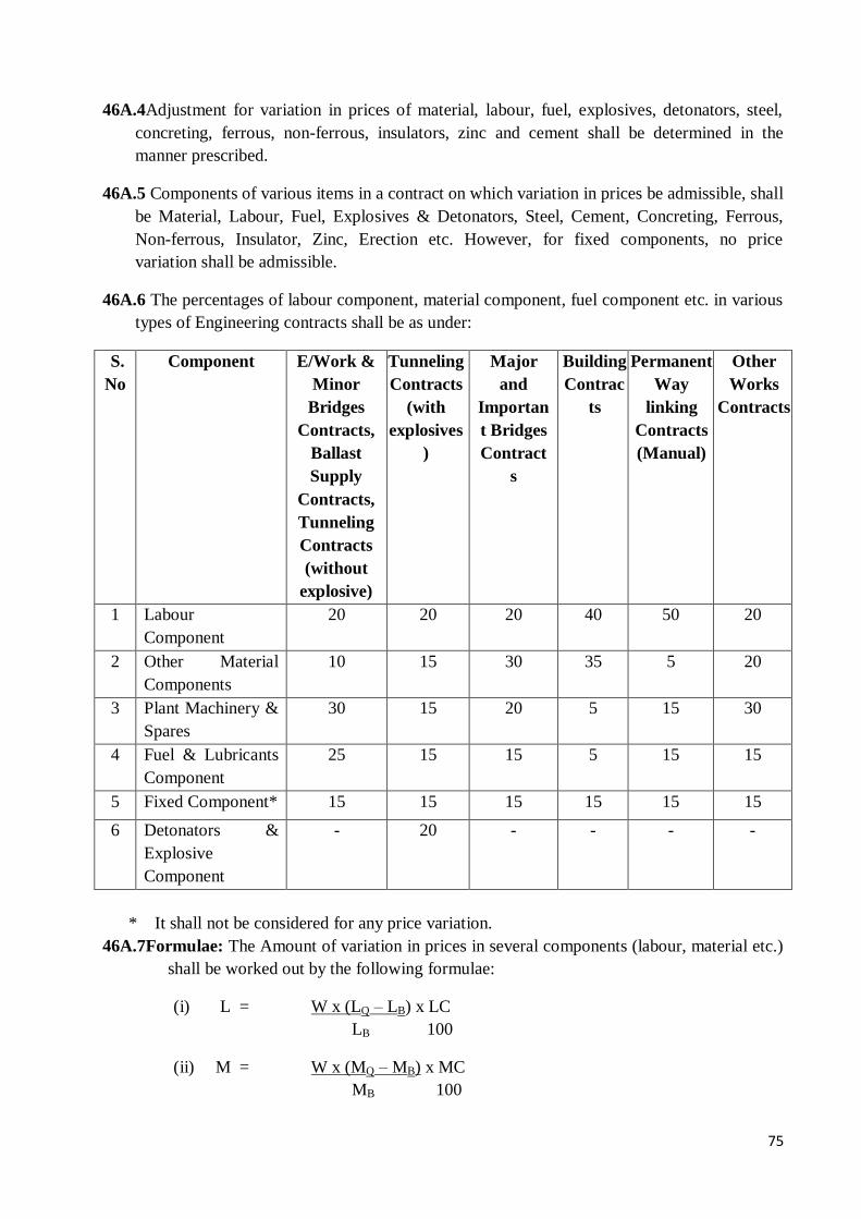
75
46A.4Adjustment for variation in prices of material, labour, fuel, explosives, detonators, steel,
concreting, ferrous, non-ferrous, insulators, zinc and cement shall be determined in the
manner prescribed.
46A.5 Components of various items in a contract on which variation in prices be admissible, shall
be Material, Labour, Fuel, Explosives & Detonators, Steel, Cement, Concreting, Ferrous,
Non-ferrous, Insulator, Zinc, Erection etc. However, for fixed components, no price
variation shall be admissible.
46A.6 The percentages of labour component, material component, fuel component etc. in various
types of Engineering contracts shall be as under:
S.
No
Component E/Work &
Minor
Bridges
Contracts,
Ballast
Supply
Contracts,
Tunneling
Contracts
(without
explosive)
Tunneling
Contracts
(with
explosives
)
Major
and
Importan
t Bridges
Contract
s
Building
Contrac
ts
Permanent
Way
linking
Contracts
(Manual)
Other
Works
Contracts
1 Labour
Component
20 20 20 40 50 20
2 Other Material
Components
10 15 30 35 5 20
3 Plant Machinery &
Spares
30 15 20 5 15 30
4 Fuel & Lubricants
Component
25 15 15 5 15 15
5 Fixed Component* 15 15 15 15 15 15
6 Detonators &
Explosive
Component
- 20 - - - -
* It shall not be considered for any price variation.
46A.7Formulae: The Amount of variation in prices in several components (labour, material etc.)
shall be worked out by the following formulae:
(i) L = W x (LQ – LB) x LC
LB 100
(ii) M = W x (MQ – MB) x MC
MB 100
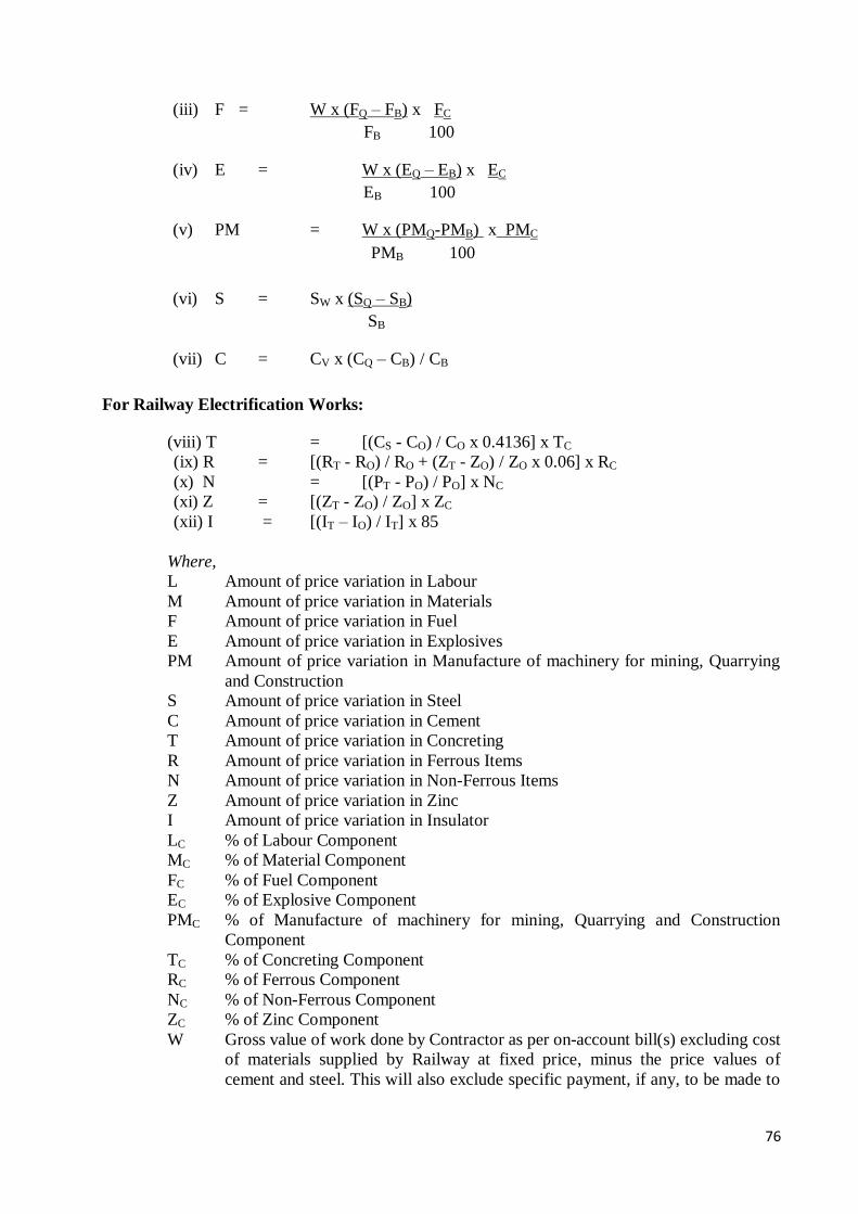
76
(iii) F = W x (FQ – FB) x FC
FB 100
(iv) E = W x (EQ – EB) x EC
EB 100
(v) PM = W x (PMQ-PMB) x PMC
PMB 100
(vi) S = SW x (SQ – SB)
SB
(vii) C = CV x (CQ – CB) / CB
For Railway Electrification Works:
(viii) T = [(CS - CO) / CO x 0.4136] x TC
(ix) R = [(RT - RO) / RO + (ZT - ZO) / ZO x 0.06] x RC
(x) N = [(PT - PO) / PO] x NC
(xi) Z = [(ZT - ZO) / ZO] x ZC
(xii) I = [(IT – IO) / IT] x 85
Where,
L Amount of price variation in Labour
M Amount of price variation in Materials
F Amount of price variation in Fuel
E Amount of price variation in Explosives
PM Amount of price variation in Manufacture of machinery for mining, Quarrying
and Construction
S Amount of price variation in Steel
C Amount of price variation in Cement
T Amount of price variation in Concreting
R Amount of price variation in Ferrous Items
N Amount of price variation in Non-Ferrous Items
Z Amount of price variation in Zinc
I Amount of price variation in Insulator
LC % of Labour Component
MC % of Material Component
FC % of Fuel Component
EC % of Explosive Component
PMC % of Manufacture of machinery for mining, Quarrying and Construction
Component
TC % of Concreting Component
RC % of Ferrous Component
NC % of Non-Ferrous Component
ZC % of Zinc Component
W Gross value of work done by Contractor as per on-account bill(s) excluding cost
of materials supplied by Railway at fixed price, minus the price values of
cement and steel. This will also exclude specific payment, if any, to be made to
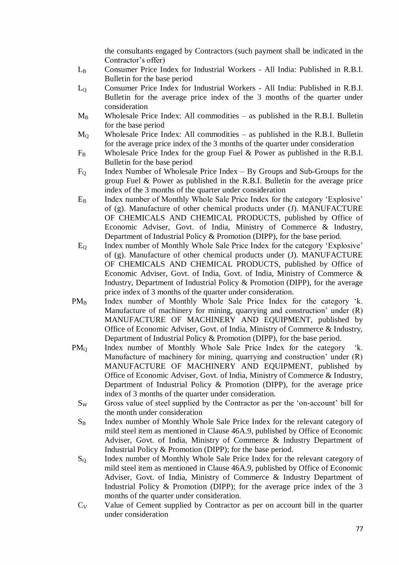
77
the consultants engaged by Contractors (such payment shall be indicated in the
Contractor’s offer)
LB Consumer Price Index for Industrial Workers - All India: Published in R.B.I.
Bulletin for the base period
LQ Consumer Price Index for Industrial Workers - All India: Published in R.B.I.
Bulletin for the average price index of the 3 months of the quarter under
consideration
MB Wholesale Price Index: All commodities – as published in the R.B.I. Bulletin
for the base period
MQ Wholesale Price Index: All commodities – as published in the R.B.I. Bulletin
for the average price index of the 3 months of the quarter under consideration
FB Wholesale Price Index for the group Fuel & Power as published in the R.B.I.
Bulletin for the base period
FQ Index Number of Wholesale Price Index – By Groups and Sub-Groups for the
group Fuel & Power as published in the R.B.I. Bulletin for the average price
index of the 3 months of the quarter under consideration
EB Index number of Monthly Whole Sale Price Index for the category ‘Explosive’
of (g). Manufacture of other chemical products under (J). MANUFACTURE
OF CHEMICALS AND CHEMICAL PRODUCTS, published by Office of
Economic Adviser, Govt. of India, Ministry of Commerce & Industry,
Department of Industrial Policy & Promotion (DIPP), for the base period.
EQ Index number of Monthly Whole Sale Price Index for the category ‘Explosive’
of (g). Manufacture of other chemical products under (J). MANUFACTURE
OF CHEMICALS AND CHEMICAL PRODUCTS, published by Office of
Economic Adviser, Govt. of India, Govt. of India, Ministry of Commerce &
Industry, Department of Industrial Policy & Promotion (DIPP), for the average
price index of 3 months of the quarter under consideration.
PMB Index number of Monthly Whole Sale Price Index for the category ‘k.
Manufacture of machinery for mining, quarrying and construction’ under (R)
MANUFACTURE OF MACHINERY AND EQUIPMENT, published by
Office of Economic Adviser, Govt. of India, Ministry of Commerce & Industry,
Department of Industrial Policy & Promotion (DIPP), for the base period.
PMQ Index number of Monthly Whole Sale Price Index for the category ‘k.
Manufacture of machinery for mining, quarrying and construction’ under (R)
MANUFACTURE OF MACHINERY AND EQUIPMENT, published by
Office of Economic Adviser, Govt. of India, Ministry of Commerce & Industry,
Department of Industrial Policy & Promotion (DIPP), for the average price
index of 3 months of the quarter under consideration.
SW Gross value of steel supplied by the Contractor as per the ‘on-account’ bill for
the month under consideration
SB Index number of Monthly Whole Sale Price Index for the relevant category of
mild steel item as mentioned in Clause 46A.9, published by Office of Economic
Adviser, Govt. of India, Ministry of Commerce & Industry Department of
Industrial Policy & Promotion (DIPP); for the base period.
SQ Index number of Monthly Whole Sale Price Index for the relevant category of
mild steel item as mentioned in Clause 46A.9, published by Office of Economic
Adviser, Govt. of India, Ministry of Commerce & Industry Department of
Industrial Policy & Promotion (DIPP); for the average price index of the 3
months of the quarter under consideration.
CV Value of Cement supplied by Contractor as per on account bill in the quarter
under consideration
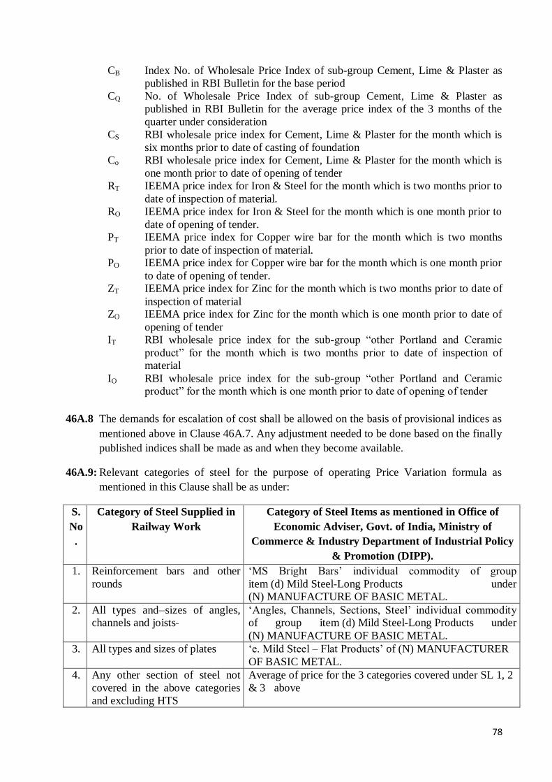
78
CB Index No. of Wholesale Price Index of sub-group Cement, Lime & Plaster as
published in RBI Bulletin for the base period
CQ No. of Wholesale Price Index of sub-group Cement, Lime & Plaster as
published in RBI Bulletin for the average price index of the 3 months of the
quarter under consideration
CS RBI wholesale price index for Cement, Lime & Plaster for the month which is
six months prior to date of casting of foundation
Co RBI wholesale price index for Cement, Lime & Plaster for the month which is
one month prior to date of opening of tender
RT IEEMA price index for Iron & Steel for the month which is two months prior to
date of inspection of material.
RO IEEMA price index for Iron & Steel for the month which is one month prior to
date of opening of tender.
PT IEEMA price index for Copper wire bar for the month which is two months
prior to date of inspection of material.
PO IEEMA price index for Copper wire bar for the month which is one month prior
to date of opening of tender.
ZT IEEMA price index for Zinc for the month which is two months prior to date of
inspection of material
ZO IEEMA price index for Zinc for the month which is one month prior to date of
opening of tender
IT RBI wholesale price index for the sub-group “other Portland and Ceramic
product” for the month which is two months prior to date of inspection of
material
IO RBI wholesale price index for the sub-group “other Portland and Ceramic
product” for the month which is one month prior to date of opening of tender
46A.8 The demands for escalation of cost shall be allowed on the basis of provisional indices as
mentioned above in Clause 46A.7. Any adjustment needed to be done based on the finally
published indices shall be made as and when they become available.
46A.9: Relevant categories of steel for the purpose of operating Price Variation formula as
mentioned in this Clause shall be as under:
S.
No
.
Category of Steel Supplied in
Railway Work
Category of Steel Items as mentioned in Office of
Economic Adviser, Govt. of India, Ministry of
Commerce & Industry Department of Industrial Policy
& Promotion (DIPP).
1. Reinforcement bars and other
rounds
‘MS Bright Bars’ individual commodity of group
item (d) Mild Steel-Long Products under
(N) MANUFACTURE OF BASIC METAL.
2. All types and sizes of angles,
channels and joists
‘Angles, Channels, Sections, Steel’ individual commodity
of group item (d) Mild Steel-Long Products under
(N) MANUFACTURE OF BASIC METAL.
3. All types and sizes of plates ‘e. Mild Steel – Flat Products’ of (N) MANUFACTURER
OF BASIC METAL.
4. Any other section of steel not
covered in the above categories
and excluding HTS
Average of price for the 3 categories covered under SL 1, 2
& 3 above
79
46A.10 Price Variation During Extended Period of Contract
The price adjustment as worked out above, i.e. either increase or decrease shall be
applicable up to the stipulated date of completion of work including the extended period of
completion where such extension has been granted under Clause 17-A, of the Indian
Railways Standard General Conditions of Contract. However, where extension of time has
been granted due to contractor’s failure under Clause 17-B of the Standard General
Conditions of Contract, price adjustment shall be done as follows:
(a) In case the indices increase above the indices applicable to the last month of original
completion period or the extended period under clause 17-A, the price adjustment for
the period of extension granted under Clause 17-B shall be limited to the amount
payable as per the indices applicable to the last month of the original completion period
or the extended period under Clause 17- A of the Standard General Conditions of
Contract; as the case may be.
(b) In case the indices fall below the indices applicable to the last month of
original/extended period of completion under clause 17-A, as the case may be; then the
lower indices shall be adopted for the price adjustment for the period of extension under
Clause 17-B of the Standard General Conditions of Contract.
47.0 Maintenance of works :- The Contractor shall at all times during the progress and
continuance of the works and also for the period of Defect Laibility (Defect Liability
period) specified in the Tender Form after the date of issue of the certificate of completion
by the Engineer or any other earlier date subsequent to the completion of the works that may
be fixed by the Engineer be responsible for and effectively maintain and uphold in good
substantial, sound and perfect condition all and every part of the works and shall make
good from time to time and at all times as often as the Engineer shall require, any damage
or defect that may during the above period arise in or be discovered or be in any way
connected with the works, provided that such damage or defect is not directly caused
by errors in the contract documents, act of providence or insurrection or civil riot,
and the contractor shall be liable for and shall pay and make good to the DFCCIL or other
persons legally entitled thereto whenever required by the Engineer so to do, all losses,
damages, costs and expenses they or any of them may incur or be put or be liable to by
reasons or in consequence of the operations of the Contractor or of his failure in any respect.
48.(1)Certificate of completion of works:- As soon as in the opinion of the Engineer, the
works has been completed and has satisfactorily passed any final test or tests that may be
prescribed, the Engineer shall issue a certificate of completion duly indicating the date of
completion in respect of the work and the period of maintenance of the work shall
commence from the date of completion mentioned in such certificate. The certificate, inter
alia, should mention that the work has been completed in all respects and that all the
contractual obligations have been fulfilled by the Contractor and that there is no due from
80
the Contractor to DFCCIL against the contract concerned.
The Engineer may also issue such a certificate indicating date of completion with respect
to any part of the work (before the completion of the whole of work), which has been both
completed to the satisfaction of the Engineer and occupied or used by the DFCCIL. When
any such certificate is given in respect of part of a work, such part shall be considered as
completed and the period of maintenance of such part shall commence from the date of
completion mentioned in the completion certificate issued for that part of the work.
48.(2)Contractor not absolved by completion Certificate:- The Certificate of completion in
respect of the works referred to in sub-clause (1) of this clause shall not absolve the
Contractor from his liability to make good any defects imperfections, shrinkages or faults
which may appear during the period of maintenance specified in the tender arising in the
opinion of the Engineer from materials or workmanship not in accordance with the drawings
or specifications or instruction of the Engineer, which defects, imperfections, shrinkages or
faults shall upon the direction in writing of the Engineer be amended and made good by the
Contractor at his own cost: and in case of default on the part of Contractor the Engineer
may employ labour and materials or appoint another Contractor to amend and make
good such defects, imperfections, shrinkages and faults and all expenses consequent thereon
and incidental thereto shall be borne by the Contractor and shall be recoverable from any
moneys due to him under the contract.
48.(3)Final Supplementary Agreement: After the work is completed or otherwise concluded by
the parties with mutual consent, and taken over by the DFCCIL as per terms and conditions
of the contract agreement, and there is unequivocal no claim on either side under the
Contract other than as mentioned in item 4 of Form no. 20, the parties shall execute the Final
Supplementary Agreement as per Form No. 20.
49. Approval only by maintenance Certificate: - No certificate other than maintenance
certificate referred to in Clause 50 of the conditions shall be deemed to constitute approval
of any work or other matter in respect of which it is issued or shall be taken as an admission
of the due performance of the contract or any part thereof.
50.(1) Maintenance Certificate: - The Contract shall not be considered as completed until a
Maintenance Certificate shall have been signed by the Engineer stating that the works
have been completed, Defect libility Period is over and created asstes are maintained to
his satisfaction. The Maintenance Certificate shall be given by the Engineer upon the
expiration of the Defect libility Period or as soon thereafter as any works ordered during
such period pursuant to sub clause (2) Clause 48 of these conditions shall have been
completed to the satisfaction of the Engineer and full effect shall be given to this Clause
notwithstanding the taking possession of or using the works or any part thereof by the
DFCCIL.

81
The Competent Authority to issue above Maintenance Certificate shall normally be the
authority who is competent to sign the contract. If this Competent Authority is of the rank
lower than Dy.CPM Grade, then a Dy.CPM Grade Officer (concerned with the work)
should issue the Certificate. The Certificate, inter alia, should mention that the work has
been completed in all respects and that all the contractual obligations have been fulfilled by
the Contractor and that there is no due from the Contractor to DFCCIL against the contract
concerned.
50.(2)Cessation of DFCCIL Liability: - The DFCCIL shall not be liable to the Contractor for
any matter arising out of or in connection with the contract of the execution of the works
unless the contractor has made a claim in writing in respect thereof before the issue of the
Maintenance Certificate under this clause.
50.(3)Unfulfilled Obligations:- Notwithstanding the issue of the Maintenance certificate the
Contractor and (subject to sub-clause 2 of this clause) the DFCCIL shall remain liable for
the fulfilment of any obligation incurred under the provision of the contract prior to the
issue of the Maintenance Certificate which remains unperformed at the time such certificate
is issued and for the purposes of determining the nature and extent of any such obligations
the contract shall be deemed to remain in force between the parties thereto.
51.(1) Final Payment:- On the Engineer’s certificate of completion in respect of the works,
adjustment shall be made and the balance of account based on the Engineer or the
Engineer’s representative’s certified measurements or Engineer’s certified “Contractor’s
Authorized Engineer’s measurements” of the total quantity of work executed by the
contractor upto the date of completion and on the accepted schedule or rates and for extra
works on rates determined under Clause 39 of these conditions shall be paid to the
Contractor subject always to any deduction which may be made under these presents and
further subject to the Contactor having signed delivered to the Engineer either a full
account in detail of all claims he may have on the DFCCIL in respect of the works or
having delivered “No Claim Certificate" and the Engineer having after the receipt of such
account given a certificate in writing that such claims are not covered under excepted
matter i.e. Clauses 7 (j), 8, 18, 22(5), 39, 43(2), 45(i)(a), 55, 55-A(5), 57, 57A, 61(1), 61(2)
and 62(1)(i) to (xv) (B) of Standard General Conditions of Contract or in any Clause (stated
as excepted matter) of the Special Conditions of the Contract, that the whole of the works
to be done under the provisions of the Contracts have been completed, that they have been
inspected by him since their completion and found to be in good and substantial order, that
all properties, works and things, removed, disturbed or injured in consequence of the works
have been properly replaced and made good and all expenses and demands incurred by or
made upon the DFCCIL for or in the respect of damage or loss by from or in consequence
of the works, have been satisfied agreeably and in conformity with the contract.
51.(2)Post Payment Audit:- It is an agreed term of contract that the DFCCIL reserves to itself
the right to carry out a post-payment audit and or technical examination of the works and the
final bill including all supporting vouchers, abstracts etc. and to make a claim on the
contractor for the refund any excess amount paid to him till the release of Security

82
Deposite of settlement of claims, which ever is later, if as a result of such examination any
over-payment to him is discovered to have made in respect of any works done or alleged to
have been done by him under the contract.
51A. Production of vouchers etc. by the Contractor: -
(i) For a contract of more than one crore of rupees, the contractor shall, whenever
required, produce or cause to be produced for examination by the Engineer any
quotation, invoice, cost or other account, book of accounts, voucher, receipt, letter,
memorandum, paper of writing or any copy of or extract from any such document
and also furnish information and returns verified in such manner as may be
required in any way relating to the execution of this contract or relevant for
verifying or ascertaining cost of execution of this contract (the decision of the
engineer on the question of relevancy of any documents, information or return being
final and binding in the parties).The contractor shall similarly produce vouchers; etc.,
if required to prove to the Engineer, that materials supplied by him, are in accordance
with the specifications laid down in the contract.
(ii) If any portion of the work in a contract of value more than one crore of rupees be
carried out by a sub-contractor or any subsidiary or allied firm or company (as per
Clause 7 of the General Conditions of Contract), the Engineer shall have power
to secure the books of such sub-contract or any subsidiary or allied firm or company,
through the contractor, and such books shall be open to his inspection.
(iii) The obligations imposed by sub clause (i) & (ii) above is without prejudice to the
obligations of the contractor under any statute rules or orders binding on the
contractor.
52.0 Withholding and lien in respect of sums claimed:- Whenever any claim or claims for
payment of a sum of money arises out of or under the contract against the contractor,
the DFCCIL shall be entitled to withhold and also have a lien to retain such sum or sums
in whole or in part from the security, if any, deposited by the contractor and for the purpose
aforesaid, the DFCCIL shall be entitled to withhold the said cash security deposit or the
security if any, furnished as the case may be and also have a lien over the same pending
finalization or adjudication of any such claim. In the event of the security being insufficient
to cover the claimed amount or amounts or if no security has been taken from the contractor,
the DFCCIL shall be entitled to withhold and have a lien to the extent of the such claimed
amount or amounts referred to supra, from any sum or sums found payable or which at any
time thereafter may become payable to the contractor under the same contract or any other
contract with this or any other DFCCIL or any Department of the Central Government
pending finalization or adjudication of any such claim.
83
It is an agreed term of the contract that the sum of money or moneys so withheld or retained
under the lien referred to above, by the DFCCIL will be kept withheld or retained as such
by the DFCCIL till the claim arising out of or under the contract is determined by the
arbitrator (if the contract governed by the arbitration clause) or by the competent court as the
case may be and that the contractor will have no claim for interest or damages whatsoever
on any account in respect of such withholding or retention under the lien referred to supra
and duly notified as such to the contractor. For the purpose of this clause, where the
contractor is a partnership firm or a limited company, the DFCCIL shall be entitled to
withhold and also have a lien to retain towards such claimed amount or amounts in
whole or in part from any sum found payable to any partner/limited company, as the case
may be whether in his individual capacity or otherwise.
52A. Lien in respect of claims in Other Contracts: -
(i) Any sum of money due and payable to the contractor (including the security deposit
returnable to him) under the contract may be withheld or retained by way of lien by
the DFCCIL, against any claim of this or any other DFCCIL or any other Department
of the Central Government in respect of a payment of a sum of money arising out of
or under any other contract made by the contractor with this or any other
Department of the Central Government.
(ii) However, recovery of claims of DFCCIL in regard to terminated contracts may be
made from the Final Bills, Security Deposits and Performance Guarantees of other
contract or contracts, executed by the contractor. The Performance Guarantees
submitted by the Contractor against other contracts, if required, may be withheld and
encashed. In addition, 10% of each subsequent ‘on-account bill’ may be withheld, if
required, for recovery of DFCCIL dues against the terminated contract.
(iii) It is an agreed term of the contract that the sum of money so withheld or retained
under this clause by the DFCCIL will be kept withheld or retained as such by the
DFCCIL till the claim arising out of or under any other contract is either mutually
settled or determined by arbitration, if the other contract is governed by arbitration
clause or by the competent court as the case may be and contractor shall have no
claim for interest or damages whatsoever on this account or on any other ground in
respect of any sum of money withheld or retained under this clause and duly
notified as such to the contractor.
53.0 Signature on Receipts for Amounts:- Every receipt for money which may become
payable or for any security which may become transferable to the Contractors under these
presents, shall, if signed in the partnership name by anyone of the partners of a
Contractor’s firm be a good and sufficient discharge to the DFCCIL in respect of the
moneys or security purported to be acknowledged thereby and in the event of death of any
of the Contractor, partners during the pendency of the contract it is hereby expressly
agreed that every receipt by anyone of the surviving Contractor partners shall if so signed

84
as aforesaid be good a sufficient discharge as aforesaid provided that nothing in this clause
contained shall be deemed to prejudice or effect any claim which the DFCCIL may
hereafter have against the legal representative of any contractor partner so dying for or in
respect to any breach of any of the conditions of the contract, provided also that nothing in
this clause contained shall be deemed to prejudice or effect the respective rights or
obligations of the Contractor partners and of the legal representatives of any deceased
Contractor partners interse.
LABOUR
54.0 Wages to Labour: - The Contractor shall be responsible to ensure compliance with the
provision of the Minimum Wages Act, 1948 (hereinafter referred to as the “said Act”) and
the Rules made there under in respect of any employees directly or through petty
contractors or subcontractors employed by him for the purpose of carrying out this contract.
If, in compliance with the terms of the contract, the Contractor supplied any labour to be
used wholly or partly under the direct orders and control of the DFCCIL whether in
connection with any work being executed by the Contractor or otherwise for the purpose
of the DFCCIL such labour shall, for the purpose of this clause, still be deemed to be
persons employed by the Contractor.
If any moneys shall, as a result of any claim or application made under the said Act be
directed to be paid by the DFCCIL, such money shall be deemed to be moneys payable to
the DFCCIL by the Contractor and on failure by the Contractor to repay the DFCCIL any
moneys paid by it as aforesaid within seven days after the same shall have been demanded,
the DFCCIL shall be entitled to recover the same from Contractor’s bills/Security Deposit
or any other dues of Contractor with the Government of India or DFCCIL.
54A. Apprentices Act: - The Contractor shall be responsible to ensure compliance with
the provisions of the Apprentices Act, 1961 and the Rules and Orders issued there under
from time to time in respect of apprentices directly or through petty contractors or sub-
contractors employed by him for the purpose of carrying out the Contract.
If the contractor directly or through petty contractors or sub-contractors fails to do so, his
failure will be a breach of the contract and the DFCCIL may, in its discretion, rescind the
contract. The contractor shall also be liable for any pecuniary liability arising on account
of any violation of the provisions of the Act.
55. Provisions of payments of Wages Act: - The Contractor shall comply with the provisions
of the Payment of Wages Act, 1936 and the rules made there under in respect of all
employees employed by him either directly or through petty Contractors or sub-contractors
in the works. If in compliance with the terms of the contract, the Contractor directly or
through petty Contractors or sub-contractors shall supply any labour to be used wholly or
85
partly under the direct orders and control of the Engineer whether in connection with the
works to be executed hereunder or otherwise for the purpose of the Engineer, such labour
shall nevertheless be deemed to comprise persons employed by the Contractor and any
moneys which may be ordered to be paid by the Engineer shall be deemed to be moneys
payable by the Engineer on behalf of the Contractor and the Engineer may on failure of the
Contractor to repay such money to the DFCCIL deduct the same from any moneys due to the
Contractor in terms of the contract. The DFCCIL shall be entitled to recover the same from
Contractor’s bills/Security Deposit or any other dues of Contractor with the Government of
India or DFCCIL all moneys paid or payable by the DFCCIL by way of compensation of
aforesaid or for costs of expenses in connection with any claim thereto and the decision of
the Engineer upon any question arising out of the effect or force of this Clause shall be final
and binding upon the Contractor.
55A.Provisions of Contract labour (Regulation and Abolition) Act, 1970:
55A.(1) The contractor shall comply with the provision of the contract labour (Regulation and
Abolition) Act, 1970 and the Contract labour (Regulation and Abolition) Central Rules
1971 as modified from time to time, wherever applicable and shall also indemnify the
DFCCIL from and against any claims under the aforesaid Act and the Rules.
55A. (2)The Contractor shall obtain a valid licence under the aforesaid Act as modified from
time to time before the commencement of the work and continue to have a valid licence
until the completion of the work. Any failure to fulfil the requirement shall attract the
penal provision of the Act.
55A. (3)The Contractor shall pay to the labour employed by him directly or through
subcontractors the wages as per provision of the aforesaid Act and the Rules wherever
applicable. The Contractor shall notwithstanding the provisions of the contract to the
contrary, cause to be paid the wages to labour indirectly engaged on the works including
any engaged by subcontractors in connection with the said work, as if the labour had been
immediately employed by him.
55A. (4) In respect of all labour directly or indirectly employed in the work for performance of
the contractor’s part of the contract, the Contractor shall comply with or cause to be
complied with the provisions of the aforesaid Act and Rules wherever applicable.
55A.(5) In every case in which, by virtue of the provisions of the aforesaid Act or the rules, the
DFCCIL is obliged to pay any amount of wages to a workman employed by the Contractor
or his sub-contractor in execution of the work or to incur any expenditure on account of the
contingent, liability of the DFCCIL due to the Contractor's failure to fulfill his statutory
obligations under the aforesaid Act or the rules, the DFCCIL will recover from the
Contractor, the amount of wages so paid or the amount of expenditure so incurred and
without prejudice to the rights of the DFCCIL under the Section 20, Sub-Section (2) and
Section 2, Sub-Section (4) of the aforesaid Act, the DFCCIL shall be at liberty to recover
86
such amount or part thereof from Contractor’s bills/Security Deposit or any other dues of
Contractor with the DFCCIL. The DFCCIL shall not be bound to contest any claim made
against it under Sub-Section (1) of Section 20 and Sub-Section (4) of Section 21 of the
aforesaid Act except on the written request of the Contractor and upon his giving to the
DFCCIL full security for all costs for which the DFCCIL might become liable in
contesting such claim. The decision of the CGM regarding the amount actually recoverable
from the Contractor as stated above shall be final and binding on the Contractor.
55B. Provisions of Employees Provident Fund and Miscellaneous Provisions Act, 1952:
The Contractor shall comply with the provisions of Para 30 & 36-B of the Employees
Provident Fund Scheme, 1952; Para 3 & 4 of Employees’ Pension Scheme, 1995; and
Para 7 & 8 of Employees Deposit Linked Insurance Scheme, 1976; as modified from time
to time through enactment of “Employees Provident Fund & Miscellaneous Provisions
Act, 1952”, wherever applicable and shall also indemnify the DFCCIL from and against
any claims under the aforesaid Act and the Rules.
55C.(i) Contractor is to abide by the provisions of Payment of Wages act & Minimum Wages
act in terms of clause 54, 55, 55A and 55B of Indian Railways General Condition of
Contract. In order to ensure the same, an application has been developed and hosted on
website ‘www.shramikkalyan.indianrailways.gov.in’. Contractor shall register his
firm/company etc. and upload requisite details of labour and their payment in this portal.
These details shall be available in public domain. The Registration/ updation of Portal
shall be done as under:
(a) Contractor shall apply for one-time registration of his company/firm etc. in the
Shramikkalyan portal with requisite details subsequent to issue of Letter of
Acceptance. Engineer shall approve the contractor’s registration in the portal
within 7 days of receipt of such request.
(b) Contractor once approved by any Engineer, can create password with login ID
(PAN No.) for subsequent use of portal for all Letter of Acceptances (LoAs) issued
in his favour.
(c) The contractor once registered on the portal, shall provide details of his Letter of
Acceptances (LoA) / Contract Agreements on shramikkalyan portal within 15 days
of issue of any LoA for approval of concerned Engineer. Engineer shall update (if
required) and approve the details of LoA filled by contractor within 7 days of
receipt of such request.
(d) After approval of LoA by Engineer, contractor shall fill the salient details of
contract labours engaged in the contract and ensure updating of each wage
payment to them on shramikkalyan portal on monthly basis.
87
(e) It shall be mandatory upon the contractor to ensure correct and prompt uploading
of all salient details of engaged contractual labour & payments made thereof after
each wage period.
(ii) While processing payment of any ‘On Account bill’ or ‘Final Bill’ or release of
‘Advances’ or ‘Performance Guarantee / Security deposit’, contractor shall submit a
certificate to the Engineer or Engineer’s representatives that “I have uploaded the
correct details of contract labours engaged in connection with this contract and
payments made to them during the wage period in Railway’s Shramikkalyan portal at
‘www.shramikkalyan.indianrailways.gov.in’ till ____Month, ____Year.”
55-DProvisions of “The Building and Other Construction Workers (Regulation of
Employment and Conditions of Service) Act, 1996” and “The Building and Other
Construction Workers’ Welfare Cess Act, 1996”:
The tenderers, for carrying out any construction work, shall get themselves registered
with the Registering Officer under Section-7 of the Building and Other Construction
Workers Act, 1996 and rules made thereto by the concerned State Govt., and submit
certificate of Registration issued from the Registering Officer of the concerned State
Govt. (Labour Dept.). The Cess shall be deducted from contractor’s bills as per provisions
of the Act.
56.0 Reporting of Accidents: - The Contractor shall be responsible for the safety of all
employees directly or through petty contractors or sub- contractor employed by him on the
works and shall report serious accidents to any of them however and wherever occurring on
the works to the Engineer or the Engineers Representative and shall make every arrangement
to render all possible assistance.
57.0 Provision of Workmen’s Compensation Act:- In every case in which by virtue of the
provisions of section 12 sub-section (1) of the Workmen’s Compensation Act 1923,
DFCCIL is obliged to pay compensation to a workman directly or through petty contractor
or subcontractor employed by the Contractor in executing the work, DFCCIL will recover
from the Contractor the amount of the compensation so paid, and, without prejudice to
the rights of DFCCIL under Section 12 Sub-section (2) of the said Act, DFCCIL shall be
at liberty to recover such amount or any part thereof from contractor’s bills/Security
Deposit or any other dues of Contractor with the Government of India. DFCCIL shall
not be bound to contest any claim made against it under Section 12 Sub-section (1) of the
said Act except on the written request of the Contractor and upon his giving to DFCCIL
full security for all costs for which DFCCIL might become liable in consequence of
contesting such claim.
57A. Provision of Mines Act:- The contractor shall observe and perform all the provisions of the
Mines Act, 1952 or any statutory modifications or re-enactment thereof for the time being in
force and any rules and regulations made there under in respect of all the persons directly or
through the petty contractors or sub-contractors employed by him under this contract and
shall indemnify the DFCCIL from and against any claims under the Mines Act, or the rules

88
and regulations framed there under, by or on behalf of any persons employed by him or
otherwise.
58.0 Railway/DFCCIL not to provide quarters for Contractors: - No quarters shall normally
be provided by the DFCCIL for the accommodation of the contractor or any of his staff
employed on the work. In exceptional cases where accommodation is provided to the
Contractor at the DFCCIL discretion, recoveries shall be made at such rates as may be fixed
by the DFCCIL for the full rent of the buildings and equipments therein as well as charges
for electric current, water supply and conservancy.
59.(1)Labour Camps: - The contractor shall at his own expense make adequate arrangements
for the housing, supply of drinking water and provision of latrines and urinals for his
staff and workmen, directly or through the petty contractors or sub-contractors and for
temporary crèche (Bal-mandir) where 50 or more women are employed at a time.
Suitable sites on DFCCIL land, if available, may be allotted to the contractor for the
erection of labour camps, either free of charge or on such terms and conditions that may
be prescribed by the DFCCIL. All camp sites shall be maintained in clean and sanitary
conditions by the contractor at his own cost.
59.(2)Compliance to rules for employment of labour:- The contractor(s) shall conform to all
laws, by-laws rules and regulations for the time being in force pertaining to the employment
of local or imported labour and shall take all necessary precautions to ensure and preserve
the health and safety of all staff employed directly or through petty contractors or sub-
contractors on the works.
59.(3)Preservation of peace: - The contractor shall take requisite precautions and use his
best endeavours to
(i) Prevent any riotous or unlawful behaviour by or amongst his workmen and other
employed directly or through the petty contractors or sub-contractors on the works and for
the preservation of peace and protection of the inhabitants and
(ii) Security of property in the neighbourhood of the works. In the event of the DFCCIL
requiring the maintenance of a special Police Force at or in the vicinity of the site during the
tenure of works, the expenses thereof shall be borne by the contractor and if paid by the
DFCCIL shall be recoverable from the contractor.
59.(4)Sanitary Arrangements: - The contractor shall obey all sanitary rules and carry out all
sanitary measures that may from time to time be prescribed by the Local Medical Authority
and permit inspection of all sanitary arrangements at all times by the Engineer, the
Engineer’s Representative or the Medical staff of the Local Medical Authority.
59.(5)Outbreak of infectious disease: - The contractor shall remove from his camp such
labour and their families as refuse protective inoculation and vaccination when called upon

89
to do so by the Engineer or the Engineer’s representative on the advice of the Local Medical
Authority. Should cholera, plague or other infectious disease break out, the contractor shall
burn the huts, beddings, clothes and other belongings of or used by the infected parties and
promptly erect new huts on health sites as required by the Engineer, failing which within the
time specified in the Engineer’s requisition, the work may be done by the DFCCIL and the
cost therefore recovered from the contractor.
59.(6)Deleted
59.(7)Medical facilities at site: - The Contractor shall provide medical facilities at the site as
may be prescribed by the Engineer on the advice of the L o c a l Medical Authority
in relation to the strength of the Contractor’s resident staff and workmen.
59.(8)Use of intoxicants: - The sale of ardent spirits or other intoxicating beverages
upon the work or in any of the buildings, encampments or tenements owned, occupied by
or within the control of the contractor or any of his employees shall be forbidden and the
Contractor shall exercise his influence and authority to the utmost extent to secure strict
compliance with this condition.
59.(9)Restrictions On The Employment Of Retired Engineers Of Railway/DFCCIL
Services Within one Year Of Their Retirement: The Contractor shall not, if he is a
retired Government Engineer of Gazetted rank, himself engage in or employ or associate a
retired Government Engineer of Gazetted rank, who has not completed one year from the
date of retirement, in connection with this contract in any manner whatsoever without
obtaining prior permission of the President and if the Contractor is found to have
contravened this provision it will constitute a breach of contract and administration will be
entitled to terminate the contract and forfeit his Performance Guarantee as well as Security
Deposit.
60.(1)Non-employment of labours below the age of 15: - The Contractor shall not employ
children below the age of 15 as labourers directly or through petty contractors or
subcontractors for the execution of work.
60.(2)Medical Certificate of fitness for labour: - It is agreed that the contractor shall not
employ a person above 15 and below 19 years of age for the purpose of execution of work
under the contract unless a medical certificate of fitness in the prescribed form (Proforma
at Form No. 15) granted to him by a certifying surgeon certifying that he is fit to work as
an adult, is obtained and kept in the custody of the contractor or a person nominated by
him in this behalf and the person carries with him, while at work; a token giving a
reference to such certificate. It is further agreed that the responsibility for having the
adolescent examined medically at the time of appointment or periodically till he attains the
age of 19 years shall devolve entirely on the contractor and all the expenses to be
incurred on this account shall be borne by him and no fee shall be charged from the
adolescent or his parent for such medical examination.
90
60.(3)Period of validity of medical fitness certificate: - A certificate of fitness granted or
renewed for the above said purposes shall be valid only for a period of one year at a time.
The certifying surgeon shall revoke a certificate granted or renewed if in his opinion the
holder of it is, no longer fit for work in the capacity stated therein. Where a certifying
surgeon refuses to grant or renew a certificate or revoke a certificate, he shall, if so,
required by the person concerned, state his reasons in writing for doing so.
60.(4)Medical re-examination of labourer:- Where any official appointed in this behalf by
the Ministry of labour is of the opinion that any person employed in connection with the
execution of any work under this contract in the age group 15 to 19 years is without a
certificate of fitness or is having a certificate of fitness but no longer fit to work in the
capacity stated in the certificate, he may serve on the Contractor, or on the person
nominated by him in the regard, a notice requiring that such persons shall be examined
by a certifying surgeon and such person shall not if the concerned official so directs, be
employed or permitted to do any work under this contract unless he has been medically
examined and certified that he is fit to work in the capacity stated in the certificate.
EXPLANATIONS:
(1) Only qualified medical practitioners can be appointed as “Certifying Surgeons” and the
term “Qualified Medical Practitioners” means a person holding a qualification granted
by an authority specified in the Schedule to the Indian Medical Degrees Act, 1916 (VII
to 1916) or in the Schedule to the Indian Medical Council Act, 1933 (XXVII) of 1933.
(2) The Certifying surgeon may be a medical officer in the service of State or Municipal
Corporation.
DETERMINATION OF CONTRACT
61.(1) Right of D FCCIL of determine the contract:- The DFCCIL shall be entitled
to determine and terminate the contract at any time should, in the DFCCIL’s
opinion, the cessation of work becomes necessary owing to paucity of funds or from any
other cause whatever, in which case the value of approved materials at site and of work
done to date by the Contractor will be paid for in full at the rate specified in the contract.
Notice in writing from the DFCCIL of such determination and the reasons therefore shall
be conclusive evidence thereof.
61. (2) Payment on determination of contract: - Should the contract be determined under sub
clause (1) of this clause and the Contractor claims payment for expenditure incurred by
him in the expectation of completing the whole of the work, the DFCCIL shall admit and
consider such claims as are deemed reasonable and are supported by vouchers to the
satisfaction of the Engineer. The DFCCIL’s decision on the necessity and propriety of
such expenditure shall be final and conclusive.
61.(3) The contractor shall have no claim to any payment of compensation or otherwise,
howsoever on account of any profit or advantage which he might have derived from the

91
execution of the work in full but which he did not derive in consequence of determination
of contract.
62.(1) Determination of contract owing to default of contractor: - I f t he Contractor
should: -
(i) Becomes bankrupt or insolvent, or
(ii) Make an arrangement with of assignment in favour of his creditors, or agree to carry
out the contract under a Committee of Inspection of his creditors, or
(iii) Being a Company or Corporation, go into liquidation (other than a voluntary
liquidation for the purposes of amalgamation or reconstruction), or
(iv) Have an execution levied on his goods or property on the works, or
(v) Assign the contract or any part thereof otherwise than as provided in Clause 7 of
these conditions, or
(vi) Abandon the contract, or
(vii) Persistently disregard the instructions of the Engineer, or contravene any
provision of the contract, or
(viii) Fail to adhere to the agreed programme of work by a margin of 10% of the
stipulated period, or
(ix) Fail to execute the contract documents in terms of Clause 1.3.7 of the Preamble and
Instructions to Bidder in Part-I, Chapter-III of Tender Document.
(x) Fails to submit the documents pertaining to identity of JV and PAN in terms of Clause
1.3.17.11 of Tender Form available in the Regulations for Tenders and Contracts.
(xi) Fail to remove materials from the site or to pull down and replace work after receiving
from the Engineer notice to the effect that the said materials or works have been
condemned or rejected under Clause 25 and 27 of these Conditions, or
(xii) Fail to take steps to employ competent or additional staff and labour as required under
Clause 26 of the Conditions, or
(xiii) Fail to afford the Engineer or Engineer’s representative proper facilities for
inspecting the work or any part thereof as required under clause 28 of the
conditions, or
(xiv) Promise, offer or give any bribe, commission, gift or advantage either himself or
through his partner, agent or servant to any officer or employee of the DFCCIL or to
any person on his or on their behalf in relation to the execution of this or any other
92
contract with this DFCCIL.
(xv) Fail to adhere to the provisions specified in “Preamble & Instructions to
Tenderers”, Part-I, Chapter-III of Tender Document or Provision of above Clause
59(9).
(xvi) Submits copy of fake documents/certifications in support of credentials,
submitted by the tenderer
Then and in any of the said Clause, the Engineer on behalf of the DFCCIL may serve the
Contractor with a notice (Proforma at Form no. 16) in writing to that effect and if the
Contractor does not within seven days after the delivery to him of such notice proceed to
make good his default in so far as the same is capable of being made good and carry on the
work or comply with such directions as aforesaid of the entire satisfaction of the Engineer,
the DFCCIL shall be entitled after giving 48 hours’ notice (Proforma at Form no. 17 or
17A, as the case may be) in writing under the hand of the Engineer to rescind the contract
as a whole or in part or parts (as may be specified in such notice) and after expiry of 48
hours’ notice, a final termination notice (Proforma at Form no. 16 or 18A, as the case
may be) should be issued.
Note: Engineer at his discretion may resort to the part termination of contract with notices
(Proforma at Form no. 16, 17A and 18A), only in cases where progress of work is
more than or equal to 80% of the original scope of work.
62.(2) Right of DFCCIL after, rescission of contract owing to default of contractor:
In the event of any or several of the courses, referred to in sub-clause (1) of the clause,
being adopted.
(a) The Contractor shall have no claim to compensation for any loss sustained by him by
reason of his having purchased or procured any materials or entered into any
commitments or made any advances on account of or with a view to the execution of
the works or the performance of the contract and Contractor shall not be entitled to
recover or be paid any sum for any work thereto for actually performed under the
contract unless and until the Engineer shall have certified the performance of such
work and the value payable in respect thereof and the Contractor shall only be entitled
to be paid the value so certified.
(b) In the contract which has been rescinded as a whole, the Security Deposit already with
DFCCIL under the contract shall be encashed/ forfeited and the Performance
Guarantee already submitted for the contract shall be encashed. The balance work
shall be got done independently without risk & cost of the failed Contractor. The
failed Contractor shall be debarred from participating in the tender for executing the
balance work. If the failed Contractor is a JV or a Partnership firm, then every
93
member/partner of such a firm shall be debarred from participating in the tender for
the balance work in his/her individual capacity or as a partner of any other JV
/partnership firm.
Further the authorized representative of failed Contractor cannot be accepted as
authorized representative in new contract.
(c) In the contract rescinded in part or parts,
(i) The full Performance Guarantee for the contract shall be recovered. No additional
Performance Guarantee shall be required for balance of work being executed
through the part terminated contract. The contract value of part terminated contract
stands reduced to the balance value of work under the contract.
(ii) The Security Deposit of part terminated contract shall be dealt as per clause 16(2)
of GCC.
(iii) The defaulting Contractor shall not be issued any completion certificate for the
contract.
(iv) The balance work shall be got done independently without risk & cost of the failed
Contractor. The failed Contractor shall be debarred from participating in the tender
for executing the balance work. If the failed Contractor is a JV or a Partnership
firm, then every member/partner of such a firm shall be debarred from participating
in the tender for the balance work in his/her individual capacity or as a partner of
any other JV /partnership firm.
(v) Further the authorized representative of failed Contractor will not be accepted as
authorized representative in new contract.
(d) The Engineer or the Engineer's Representative shall be entitled to take possession of
any materials, tools, implements, machinery and buildings on the works or on the
property on which these are being or ought to have been executed, and to retain and
employ the same in the further execution of the works or any part thereof until the
completion of the works without the Contractor being entitled to any compensation
for the use and employment thereof or for wear and tear or destruction thereof.
(e) The Engineer shall as soon as may be practicable after removal of the Contractor fix
and determine ex-parte or by or after reference to the parties or after such
investigation or enquiries as he may consider fit to make or institute and shall certify
what amount (if any) had at the time of rescission of the contract been reasonably
earned by or would reasonably accrue to the Contractor in respect of the work then
actually done by him under the contract and what was the value of any unused, or
partially used materials, any constructional plant and any temporary works upon the
site. The legitimate amount due to the Contractor after making necessary deductions
and certified by the Engineer should be released expeditiously.
SETTLEMENT OF DISPUTES

94
63.0 Conciliation of disputes: All disputes and differences of any kind whatsoever arising
out of or in connection with the contract, whether during the progress of the work or
after its completion and whether before or after the determination of the contract, shall
be referred by the Contractor to the CGM)" through “Notice of Dispute” provided that
no such notice shall be served later than 30 days after the date of issue of Completion
Certificate by the Engineer. MD/DFCCIL shall, within 30 days after receipt of the
Contractor’s “Notice of Dispute”, notify the name of conciliator(s) to the Contractor.
The Conciliator(s) shall assist the parties to reach an amicable settlement in an
independent and impartial manner within the terms of contract.
If the parties reach agreement on a settlement of the dispute, they shall draw up and sign
a written settlement agreement duly signed by DFCCIL, Contractor and conciliator(s).
When the parties sign the settlement agreement, it shall be final and binding on the
parties.
The parties shall not initiate, during the conciliation proceedings, any arbitral or judicial
proceedings in respect of a dispute that is the subject matter of the conciliation
proceedings.
The conciliation proceedings shall be terminated as per Section 76 of ‘The Arbitration
and Conciliation Act, 1996.
63.1 Matters Finally Determined by the DFCCIL: All disputes and differences of any kind
whatsoever arising out of or in connection with the contract, whether during the progress
of the work or after its completion and whether before or after the determination of the
contract, shall be referred by the Contractor to the MD/DFCCIL and the MD/DFCCIL
shall, within 120 days after receipt of the Contractor’s representation, make and notify
decisions on all matters referred to by the Contractor in writing provided that matters for
which provision has been made in Clauses 7(j), 8, 18, 22(5), 39, 43(2), 45(i)(a), 55, 55-
A(5), 57, 57A, 61(1), 61(2) and 62(1) of Standard General Conditions of Contract or in
any Clause (stated as excepted matter) of the Special Conditions of the Contract, shall be
deemed as ‘excepted matters’ (matters not arbitrable) and decisions of the DFCCIL
Authority, thereon shall be final and binding on the Contractor; provided further that
‘excepted matters’ shall stand specifically excluded from the purview of the Arbitration
Clause.
64. (1) Demand for Arbitration: -
64. (1)(i) In the event of any dispute or difference between the parties hereto as to the
construction or operation of this contract, or the respective rights and liabilities of the
parties on any matter in question, dispute or difference on any account or as to the
withholding by the DFCCIL of any certificate to which the Contractor may claim to be
entitled to, or if the DFCCIL fails to make a decision within 120 days, then and in any such
case, but except in any of the “excepted matters” referred to in Clause 63.1 of these
95
Conditions, the Contractor, after 120 days but within 180 days of his presenting his final
claim on disputed matters shall demand in writing that the dispute or difference be referred
to arbitration.
64.(1) (ii)(a)The demand for arbitration shall specify the matters which are in question, or subject
of the dispute or difference as also the amount of claim item-wise. Only such dispute or
difference, in respect of which the demand has been made, together with counter claims or
set off, given by the DFCCIL, shall be referred to arbitration and other matters shall not be
included in the reference.
64.(1)(ii)(b)The parties may waive off the applicability of Sub-Section 12(5) of Arbitration and
Conciliation (Amendment) Act 2015, if they agree for such waiver in writing, after dispute
having arisen between them, in the format given under (Form No. 25) of these conditions.
64.(1)(iii)(a)The Arbitration proceedings shall be assumed to have commenced from the day, a
written and valid demand for arbitration is received by the DFCCIL.
64.(1)(iii)(b)The claimant shall submit his claim stating the facts supporting the claims alongwith
all the relevant documents and the relief or remedy sought against each claim within a
period of 30 days from the date of appointment of the Arbitral Tribunal.
64.(1)(iii)(c)The DFCCIL shall submit its defence statement and counter claim(s), if any, within a
period of 60 days of receipt of copy of claims from Tribunal, unless otherwise extension
has been granted by Tribunal.
64.(1)(iii)(d)Place of Arbitration: The place of arbitration would be within the geographical
limits of the CGM Unit where the cause of action arose or the Headquarters of the DFCCIL
or any other place with the written consent of both the parties.
64.(1)(iv) No new claim shall be added during proceedings by either party. However, a party may
amend or supplement the original claim or defence thereof during the course of arbitration
proceedings subject to acceptance by Tribunal having due regard to the delay in making it.
64.(1)(v)If the Contractor(s) does/do not prefer his/their specific and final claims in writing,
within a period of 90 days of receiving the intimation from the DFCCIL that the final bill is
ready for payment, he/they will be deemed to have waived his/their claim(s) and the
DFCCIL shall be discharged and released of all liabilities under the contract in respect of
these claims.
64.(2) Obligation During Pendency of Arbitration: Work under the contract shall, unless
otherwise directed by the Engineer, continue during the arbitration proceedings, and no
payment due or payable by the Railway shall be withheld on account of such proceedings,
provided, however, it shall be open for Arbitral Tribunal to consider and decide whether or
not such work should continue during arbitration proceedings.
64.(3) Appointment of Arbitrator
96
64.(3)(a)(i)In cases where the total value of all claims in question added together does not exceed
₹ 1,00,00,000/- (Rupees One Crore), the Arbitral Tribunal shall consist of a Sole
Arbitrator nominated by MD/DFCCIL from approved panel of Arbitrators in DFCCIL.
The sole arbitrator shall be appointed within 60 days from the day when a written and
valid demand for arbitration is received by MD/DFCCIL.
64.(3)(a)(ii) In cases not covered by the Clause 64(3)(a)(i), the Arbitral Tribunal shall consist of a
panel of three Officials, as the Arbitrators. For this purpose, the DFCCIL will send a
panel of Three (3) names empanelled Arbitrators to work as Arbitrator to the
contractor within 60 days from the day when a written and valid demand for
Arbitration is received by the MD/DFCCIL. Contractor will be asked to suggest to
MD/DFCCIL at least 2 names out of the panel for appointment as Contractor’s
nominee within 30 days from the date of dispatch of the request by DFCCIL. The
MD/DFCCIL shall appoint at least one out of them as the Contractor’s nominee and
will, also simultaneously appoint the second Arbitrator.
(b) Third member, who will also act as the presiding member, will be appointed by
mutual consent of the first two members from the list of empanelled DFCCIL
Arbitrators. If these two members fail to reach an agreement on the third member then,
on request by either or both parties, appointment will be made by the MD/DFCCIL.
(c) The tribunal shall have full power to open up, review and revise any certificate,
determination, instruction, opinion or valuation of the Engineer, and any decision of
the concialiator/s relevant to the dispute.
(d) Neither party shall be limited in the proceedings before the tribunal to the evidence or
arguments previously put before the conciliator/s to obtain its decision, or to the
reasons for dissatisfaction given in its notice of dissatisfaction.
(e) Arbitration may be commenced prior to or after completion of the works. The
obligations of the Parties, the Engineer and the conciliator/s shall not be altered by
reason of any arbitration being conducted during the progress of the Works.
64.(3)(a)(iii) If one or more of the arbitrators appointed as above refuses to act as arbitrator,
withdraws form his office as arbitrator, or vacates his/their officer/offices or is/are unable
or unwilling to perform his functions as arbitrator for any reason whatsoever or dies or in
the opinion of the MD/DFCCIl fails to act without undue delay, the MD/DFCCIL shall
appoint new arbitrator/arbitrators to act in his/their place in the same manner in which the
earlier arbitrator/arbitrtors had been appointed. Such re-constituted Tribunal may, at its
discretion, proceed with the reference from the stage at which it was left by the previous
arbitrator(s).
64.(3)(b)(i):(a) The Arbitral Tribunal shall have power to call for such evidence by way of
affidavits or otherwise as the Arbitral Tribunal shall think proper, and it shall be the duty
of the parties hereto to do or cause to be done all such things as may be necessary to
enable the Arbitral Tribunal to make the award without any delay. The proceedings shall
normally be conducted on the basis of documents and written statements.
97
(b) Before proceedings into the merits of any dispute, the Arbitral Tribunal shall first
decide and pass its orders over any plea submitted/objections raised by any party, if any,
regarding appointment of Arbitral Tribunal, validity of arbitration agreement, jurisdiction
and scope of the Tribunal to deal with the dispute(s) submitted to arbitration, applicability
of time ‘limitation’ to any dispute, any violation of agreed procedure regarding conduct of
the arbitral proceedings or plea for interim measures of protection and record its orders in
day to day proceedings. A copy of the proceedings duly signed by all the members of
tribunal should be provided to both the parties.
64.3(c)(i):The abitral award shall state item wise, the sum and reasons upon which it is based.
The analysis and reasons shall be detailed enough so that the award could be inferred
therefrom.
64.3(c)(ii):A party may apply for corrections of any computational errors, any typographical or
clerical errors or any other error of similar nature occurring in the award of a Tribunal
and interpretation of a specific point of award to Tribunal within 60 days of receipt of
the award.
64.3(c)(iii):A party may apply to Tribunal within 60 days of receipt of award to make an
additional award as to claims presented in the arbitral proceedings but omitted from the
arbitral award.
64.(4): In case of the Tribunal, comprising of three members, any ruling on award shall be
made by a majority of members of Tribunal. In the absence of such a majority, the
views of the Presiding Arbitrator shall prevail.
64.(5): Where the arbitral award is for the payment of money, no interest shall be payable on
whole or any part of the money for any period till the date on which the award is made.
64.(6): The cost of arbitration shall be borne by the respective parties. The cost shall inter-alia
include fee of the arbitrator(s), as per the rates fixed by DFCCIL from time to time and
the fee shall be borne equally by both the parties, provided parties sign an agreement in
the format given at “Form No. 25” to these conditions after/ while referring these
disputes to Arbitration. Further, the fee payable to the arbitrator(s) would be governed
by the instructions issued on the subject by DFCCIL from time to time irrespective of the
fact whether the arbitrator(s) is/are appointed by the DFCCIL or by the court of law
unless specifically directed by Hon’ble court otherwise on the matter.
64.(7) Subject to the provisions of the aforesaid Arbitration and Conciliation Act 1996 and the
rules thereunder and relevant para of General Conditions of Contract (GCC) and any
statutory modifications thereof shall apply to the appointment of arbitrators and
arbitration proceedings under this Clause.
98
PART- I
CHAPTER-V
SPECIAL CONDITIONS OF CONTRACT

99
Signature of Tenderer
PART-I
CHAPTER-V
SECTION-1
SPECIAL CONDITIONS OF CONTRACT (ELECTRICAL)
Note: The Special Conditions of contract (SCC) should be read in conjunction with the
General Conditions of Contract (GCC). However, if there is any provision in the GCC,
which is at variance with the provisions in SCC, the provisions in the Special Conditions of
Contract (SCC) shall take precedence.
1.1 DEFINITION AND INTERPRETATIONS.
In the contract documents, the following terms shall have the meanings herein assigned to
them except where the contract otherwise requires:
“Chief General Manager” shall mean the officer-in-charge of the general superintendence
and control of the unit and shall also include General Manager/Electrical and shall mean and
include their successors.
A "day" shall mean a day of 24 hours from midnight to mid night irrespective of the number
of hours worked in that day.
A "week" shall mean seven days without regard to the number of hours worked on any day in
that week.
A “month” shall mean gregorian calendar month irrespective of the number of hours worked
on any day in that month.
“Contract" shall mean and include the agreement of work order, the accepted schedule of
rates or the schedule or rates of railway modified by the tender percentage for items of works
quantified, or not quantified, the standard general conditions of contract, the special
conditions of contracts, if any; the drawing, the specifications, the special specifications, if
any and tender forms, if any.
Singular and Plural: words importing the singular number shall also include the plural and
vice versa where the context requires.
1.2 General
The special conditions of contract, shall be part of "contract documents" and the contractor
shall satisfy himself/themselves in every respect as to the true intent and meaning of these
contract documents and to the nature, extent and quality of the work required to be executed
as no claim whatsoever arising through any misunderstanding of the intention, or the meaning
of any of the terms or expressions in these contract documents, shall be entertained after the
submission of the tender. The work shall be executed in conformity with the tender
100
Signature of Tenderer
documents such as the standard general conditions of contract – 2020, special conditions &
special specifications mentioned in the contract, Indian Electricity Rules and other relevant
IR/IS specifications.
1.2.1 As per provision of Make in India Policy 2017, local component should be minimum 50% of
the Contract Value. Contractor shall be required to give undertaking along with supporting
document for the same.
1.2.2 The amended provisions for Public procurement issued by Ministry of Finanace (MoF),
Department of Expenditure, Public Procurement Division OM No. F No.6/18/2019-PPD
dated 23-07-2020 shall also be applicable in this tender.
1.2.3 Special Technical Compliance- Electrical Contractor License:
The tenderer shall have a valid Electrical Contractor License to work at 33KV issued by any
State Govt. in the name of the firm. The copy of same has to be submitted alongwith the offer.
1.2.4 Intent of plans, specification and contract documents:
The work to be carried out under this contract shall, except as otherwise provided in these
conditions, include all labour, materials, construction plant, equipment and transport which
may be required in preparation of and for the full and entire execution and successful
completion of the works. The description given in the schedule of works shall, unless
otherwise stated, be held to include carriage and cartage, carrying and hoisting, setting, fitting
and fixing in position and all other labour, necessary in and for the full and entire execution
and successful completion of the works as aforesaid in accordance with good practice and
recognized principles and any urgent and temporary works fully contingent upon the works.
1.3 Inspection and admission to site:
The contractor shall not be permitted to enter on (other than for inspection purpose) or take
possession of the site until instructed to do so by the Engineer in writing. The portion of the
site to be occupied by the contractor shall be defined and/or shown in the site plan, or this
shall be indicated by the Engineer, and the contractor shall on no account be allowed to
extend his operation beyond these areas. The contractor shall not use or allow it to be used the
site so allowed to him by the DFCCIL for any purpose other than that of executing the work.
The contractor shall make his own arrangement at his own cost for any additional land
required by him for the purpose of execution of the work. The contractor shall at his own cost
provide, if necessary or if required on the site, all temporary access thereto, to the satisfaction
of the Engineer and shall alter, adopt and maintain the same as required from time to time and
shall take up and clear them away as and when no longer required and make good all damage
done to the site. The tenderer(s) before quoting his rate shall carefully inspect the site and
shall be deemed to have satisfied himself about the nature and type of work including
ancillary works necessary for satisfactory execution of work. Site accessibility and
availability of required materials must be kept in view while quoting the rates. Many
electrical works are dependent on Civil/S&T construction works. Contractor should properly
101
Signature of Tenderer
interface and co-ordinate accordingly for execution of work. No separate cost shall be paid for
the same.
1.4 PRIORITY OF DOCUMENTS
Where there is any conflict between the various documents in the Contract, the following
order of priority shall be followed i.e. a document appearing earlier shall override the
document appearing subsequently:
a. Letter of Acceptance (LOA)
b. Schedule of items, Rates & Quantities.
c. Special Conditions of Contract.
d. Technical Specifications as given in tender documents.
e. Drawings, if any.
f. General Conditions of Contract.
g. Relevant BIS Codes.
1.5 INDEMNITY BY THE CONTRACTOR
1.5.1 Indemnity against all actions of Contractor
The Contractor shall hold and save harmless and indemnify the Client/Employer/Engineer
and their employees, from all actions, suits, proceedings, loss, costs, damages, charges, claims
and demands of every nature and description brought against or recovered from the
Client/Employer/Engineer and their employees by reason of any act or omission of the
Contractor and/or his representative and/or his Employees and/or his sub-contractors in the
execution of the works or in the guarding of the same. All the sums payable by
Client/Employer/ Engineer by way of compensation under any of these conditions shall be
recovered from the dues of the Contractor, without reference to the actual loss or damage
sustained, and whether or not any damage shall have been sustained.
1.5.2 Indemnity against all Claims of Patent rights and Royalties
The Contractor shall hold and save harmless and indemnify the Client/Employer/Engineer, his
officers and Employees from and against all claims and proceedings for or on account of
infringement by the Contractor of copyright, any patent rights, design, trademark or name,
secret process, patented or un-patented invention, articles or appliances manufactured or used
for or in connection with the works and from and against all claims, proceedings, costs,
damages, charges, and expenses whatsoever in respect thereof or in relation thereto. The
Contractor shall pay all royalties, taxes, rent and other payments or compensation, if any, for
getting the materials required for the works and due fulfillment of the contract and indemnify
Client/Employer/Engineer against any claims in this regard.
1.5.3 Damage to Life and Property
The Contractor shall be responsible for all risks to works, nearby existing structures and life
of his supervisors and workmen as also those of Employer/Client or any trespassers from
whatever cause in connection with the works until these are taken over by
Client/Employer/Engineer. The Contractor shall make good at his own expenses all loss or
damages to life and property.

102
Signature of Tenderer
1.6 PRICES
1.6.1 Rates quoted in the financial offer (financial bid) shall be inclusive of all taxes and duties
except GST. Rates shall also include transportation of material, transit insurance, e-way bill,
loading, unloading, lifting/handling of material, insurance of material at site & workers,
liaisoning with any other department, banker charges and other incidental charges. GST as
applicable shall be paid extra on the accepted rates mentioned in Schedule-I & II.
1.6.2 If any cost implication to DFCCIL is occurred on GST account because of Contractor’s default
in filing of GST returns such as no GST number, wrong GST number, mismatch of GST
number etc. , the same shall be recovered from the Contractor’s bill or any other pending/
future bill.
1.7 PRICE VARIATION CLAUSE
1.7.1 The Price Variation on Schedule-II (Civil works) shall be payable as per clause 46A of GCC.
The percentage of various components shall be taken as for Building Contracts mentioned in
clause 46A.6 of GCC.
1.7.2 The Price Variation on Schedule-I (Electrical works) shall be payable as per clause 46A of
GCC except clause 46A.4 to 46A.9 which are replaced by following clauses:-
1.7.3 Adjustment for variation in prices of labour, cement, steel, fuel, electrical equipment etc. shall
be determined in the manner prescribed.
1.7.4 Components of various items on which variation in prices be admissible, shall be Labour,
Cement, Steel, Fuel & Power, Electical wire & cables and Electrical Equipment. However, for
fixed component, no price variation shall be admissible.
1.7.5 The percentages of various components to be considered for price variation shall be as under:
S. No Component %age
1 Labour Component 7
2 Cement & Lime 3
3 Steel Long 5
4 Fuel & Power 2
5 Electrial Accessories, Wires and Cables 3
6 Electrical Machienary/ Equipment 60
7 Fixed Component* 20
*It shall not be considered for any price variation.
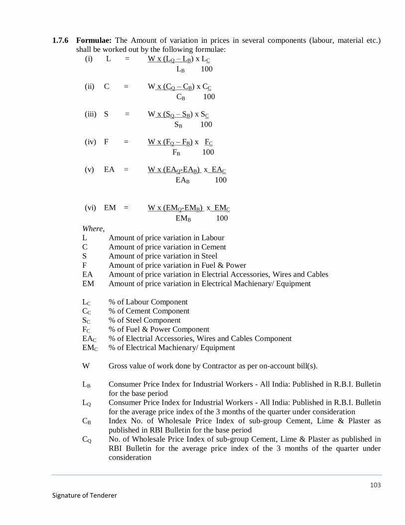
103
Signature of Tenderer
1.7.6 Formulae: The Amount of variation in prices in several components (labour, material etc.)
shall be worked out by the following formulae:
(i) L = W x (LQ – LB) x LC
LB 100
(ii) C = W x (CQ – CB) x CC
CB 100
(iii) S = W x (SQ – SB) x SC
SB 100
(iv) F = W x (FQ – FB) x FC
FB 100
(v) EA = W x (EAQ-EAB) x EAC
EAB 100
(vi) EM = W x (EMQ-EMB) x EMC
EMB 100
Where,
L Amount of price variation in Labour
C Amount of price variation in Cement
S Amount of price variation in Steel
F Amount of price variation in Fuel & Power
EA Amount of price variation in Electrial Accessories, Wires and Cables
EM Amount of price variation in Electrical Machienary/ Equipment
LC % of Labour Component
CC % of Cement Component
SC % of Steel Component
FC % of Fuel & Power Component
EAC % of Electrial Accessories, Wires and Cables Component
EMC % of Electrical Machienary/ Equipment
W Gross value of work done by Contractor as per on-account bill(s).
LB Consumer Price Index for Industrial Workers - All India: Published in R.B.I. Bulletin
for the base period
LQ Consumer Price Index for Industrial Workers - All India: Published in R.B.I. Bulletin
for the average price index of the 3 months of the quarter under consideration
CB Index No. of Wholesale Price Index of sub-group Cement, Lime & Plaster as
published in RBI Bulletin for the base period
CQ No. of Wholesale Price Index of sub-group Cement, Lime & Plaster as published in
RBI Bulletin for the average price index of the 3 months of the quarter under
consideration
104
Signature of Tenderer
SB Index No. of Wholesale Price Index of sub-group item Mild Steel- Long Products as
published in RBI Bulletin for the base period
SQ No. of Wholesale Price Index of sub-group item Mild Steel- Long Products as
published in RBI Bulletin for the average price index of the 3 months of the quarter
under consideration
FB Wholesale Price Index for the group Fuel & Power as published in the R.B.I. Bulletin
for the base period
FQ Index Number of Wholesale Price Index – By Groups and Sub-Groups for the group
Fuel & Power as published in the R.B.I. Bulletin for the average price index of the 3
months of the quarter under consideration
EAB Index No. of Wholesale Price Index of sub-group item Other Electronic and Electric
Wires and Cables as published in RBI Bulletin for the base period
EAQ No. of Wholesale Price Index of sub-group item Other Electronic and Electric Wires
and Cables as published in RBI Bulletin for the average price index of the 3 months
of the quarter under consideration
EMB Index No. of Wholesale Price Index of sub-group Manufacture of Electrical
Equipment as published in RBI Bulletin for the base period
EMQ No. of Wholesale Price Index of sub-group Manufacture of Electrical Equipment as
published in RBI Bulletin for the average price index of the 3 months of the quarter
under consideration
The demands for escalation of cost shall be allowed on the basis of provisional indices as
mentioned above
Any adjustment needed to be done based on the finally published indices shall be made as
and when they become available.
1.8 QUANTITY VARIATION:
The quantities of various items mentioned in the BOQ are tentative and may change as per
requirement during execution of work. Due to this the contract value may also change. The
variation in the contract shall be governed by Para 42 of GCC.
1.9 PERIOD OF COMPLETION OF WORK:
Period of completion for complete work shall be 09 months from the date of issue of Letter
of Acceptance. The period of completion of Civil works of substations shall be 4 months
from the date of issue of Letter of Acceptance.
1.10 MEASUREMENTS
The Contractor shall be paid for the works at rates in the accepted Schedule of Rate &
Quantities. The measurement shall be taken by the Engineer or his representative in the
presence of the Contractor or his authorized representative.
1.11 WARRANTY (Defect Liability Period):
Warranty (Defect Liability Period) of complete work including material shall be 12 months
from the date of commissioning of each system and taken over by DFCCIL as certified by
DFCCIL. During this period, any failure of system shall be attended free of cost by the

105
Signature of Tenderer
Contractor. Some items shall have OEM warranty of more than twelve months as specified in
the technical specification of the concerned item.
1.12 TERMS OF PAYMENT
1.12.1 On Account Payment:
(A) On Account Payment for items involving Supply and Erection:-
(i) 75% of accepted rates against receipt of materials.
(ii) 15% on satisfactory erection of various items.
(iii) Balance 10% on successful commissioning of the work.
(B) On Account Payment for items involving Supply only:-
(i) 80% of quoted rates against receipt of materials.
(ii) 10% on satisfactory erection of materials.
(iii) Balance 10% on successful commissioning of the work.
(C) On Account Payment for items involving Erection only:-
(i) 90% on successful erection of various items.
(ii) Balance 10% on successful commissioning of the work.
1.12.2 Requirements for Payment against Supply of Material – Payment against receipt of material
mentioned in clause 13.1 shall be made subject to complying the following:-
(i) Supplier’s delivery challan,
(ii) Inspection Certificate issued by authorized representative of the Purchaser.
(iii) Certificate of receipt of material in good condition at site/ Contractor’s depot duly
verified by the Purchaser’s Engineer.
(iv) Bank Guarantee in the prescribed form for an amount equal to total amount claimed
against supply of material. The BG will be retained by DFCCIL till the erection of
material. On completion of the erection of material, the BG may be returned to the
Contractor or be adjusted against further on account payments for supply of material.
1.13 INSURANCE
Before commencing of works, it shall be obligatory for the contractor to obtain, at his own
cost, insurance cover in the joint name of the Contractor and Employer (DFCCIL) from
reputed companies for the following requirements:
a. Contractor’s All Risk (CAR) Policy.
b. Liability for death of or injury to any person or loss or damage to any property (other
than the work) arising out the performance of the contract.
c. Construction Plant, Machinery and Equipment brought to site by the Contractor.
106
Signature of Tenderer
d. Workmen Compensation Policy.
e. Any other insurance cover as may be required by the law of the land.
f. The Contractor, if required, will engage a suitable engineer to liaise with Insurer
Company in the interest of reliazation of insurance claims at no cost to Employer.
g. Contractor/Insurance Company shall have to indemnify DFCCIL for all losses. Claims if
any given by insurance company to be given directly to DFCCIL. Decision of DFCCIL
will be binding on Contractor to distribute claim in part or full.
All insurance covers referred to in the Contract shall be effected with an Indian
Insurance Company incorporated and registered in India.
1.14 FIRE EXTINGUISHERS
The contractor shall at his own expenses provide at suitable, prominent and easily accessible
places, requisite number of fire extinguishers and buckets, some filled with sand and some
with water.
1.15 QUALITY CONTROL
The Contractor shall submit to the DFCCIL a comprehensive quality approval plan for all
materials, equipments and things to be provided under the contract. No material or equipment
shall be dispatched by the manufacture or vendor or brought to site by the Contractor until
the quality of the material or equipment has been established through
inspection and tests or through test certificates furnished by the manufacturer. In case the
DFCCIL accepts such test certificates as sufficient proof that the material or equipment
conforms to the contract document, he shall accord his approval for the dispatch of materials
or equipment.
1.16 QUALITY OF MATERIALS AND WORKMANSHIP
1. 16.1 All materials and workmanship shall be the best of the respective kinds described in the
Contract and in accordance with the instructions and directions of the DFCCIL and shall be
subjected from time to time, to such test as the DFCCIL may direct at the place of
manufacture or fabrication or on the site or at such other places as may be directed. The
Contractor shall execute the whole and every parts of the works in the substantial and
workmen like manner, both as regards to materials and workmanship, and in every respect in
strict accordance with the contract documents and in compliance with the applicable
government laws, ordinance, statues, codes, rules and regulations. The Contractor shall also
conform exactly and faithfully to the designs, drawings and instructions in writing of the
DFCCIL.
1.16.2 The designs and drawings shall have the prior approval of the Engineer in Charge before
commencement of the work.
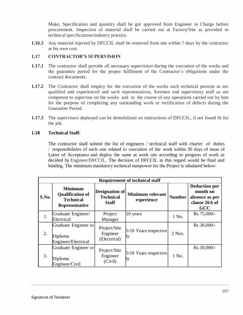
107
Signature of Tenderer
Make, Specification and quantity shall be got approved from Engineer in Charge before
procurement. Inspection of material shall be carried out at Factory/Site as provided in
technical specifications/industry practice.
1.16.3 Any material rejected by DFCCIL shall be removed from site within 7 days by the contractor
at his own cost.
1.17 CONTRACTOR’S SUPERVISION
1.17.1 The contractor shall provide all necessary supervision during the execution of the works and
the guarantee period for the proper fulfilment of the Contractor’s obligations under the
contract documents.
1.17.2 The Contractor shall employ for the execution of the works such technical persons as are
qualified and experienced and such representatives, foremen and supervisory staff as are
competent to supervise on the works and in the course of any operations carried out by him
for the purpose of completing any outstanding work or rectification of defects during the
Guarantee Period.
1.17.3 The supervisors deployed can be demobilized on instructions of DFCCIL, if not found fit for
the job.
1.18 Technical Staff:
The contractor shall submit the list of engineers / technical staff with charter of duties
/ responsibilities of each one related to execution of the work within 30 days of issue of
Letter of Acceptance and deploy the same at work site according to progress of work as
decided by Engineer/DFCCIL. The decision of DFCCIL in this regard would be final and
binding. The minimum mandatory technical manpower for the Project is tabulated below:
Requirement of technical staff
S.No.
Minimum
Qualification of
Technical
Representative
Designation of
Technical
Staff
Minimum relevant
experience Number
Deduction per
month on
absence as per
clause 26A of
GCC
1. Graduate Engineer/
Electrical
Project
Manager
10 years 1 No.
Rs 75,000/-
2.
Graduate Engineer or
Diploma
Engineer/Electrical
Project/Site
Engineer
(Electrical)
5/10 Years respective
ly 2 Nos.
Rs 30,000/-
3.
Graduate Engineer or
Diploma
Engineer/Civil
Project/Site
Engineer
(Civil)
5/10 Years respective
ly 1 No.
Rs 30,000/-
108
Signature of Tenderer
1.19 Compliance with GRIHA Guidelines
The project is pre-certified GRIHA 5 star rating. To secure 5 star GRIHA rating, a high
degree of responsibility and cooperation is necessary from the contractor. Agency is
advised to note that entire work shall be carried out in such a manner so as to satisfy
Green Building parameters/ GRIHA guidelines. Conditions of Contract specific to
Green Building Practices have been narrated in Special Conditions for Green Building
Practices (Part-I, Chapter-V, Section-5).

109
Signature of Tenderer
PART-I
CHAPTER-V
SECTION-2
SPECIAL CONDITIONS OF CONTRACT (CIVIL)
Note: The Special Conditions of contract (SCC) should be read in conjunction with the General
Conditions of Contract (GCC). However, if there is any provision in the GCC, which is at
variance with the provisions in SCC, the provisions in the Special Conditions of Contract
(SCC) shall take precedence.
2.1 TEMPORARY WORKERS’ HOUSING:
2.1.1 The bidder himself shall construct clean hygienic and well-ventilated labour housing with
adequate water supply, electrical, sanitation facilities, etc as per “Model Rules for the
Protection of Health and Sanitary Arrangement for the Workers Employed by the Contractors”
of General Conditions of Contract, or applicable Labour Regulations.
2.1.2 The contractor has to arrange for the labour passes for entry and exit of labourers at the
work site.
2.1.3 Adequate number of temporary housing units shall be constructed within o ne month of
the date of start of work to the satisfaction of Engineer.
2.1.4 Toilet blocks having WC, wash basin and bathing area @ one set for approximately 15
labours with arrangement for sewage disposal through ready to install adequate capacity
septic tank units shall be made available along with the labour huts.
2.1.5 These housing units can be inspected by Engineer and contractor will be allowed to take up
main work only after satisfactory completion of these units.
2.1.6 No extra payment shall be made by DFCCIL for construction of such temporary labour
housing.
2.2 Deleted
2.3 Procurement of fly ash, lime, AAC, gypsum bricks
2.3.1 The work involves RCC framed construction with filler walls. The brick work shall be
110
Signature of Tenderer
carried out with good quality AAC Block/ FPS/Fly Ash Lime Gypsum (FALG) bricks of
class designation as per BOQ with cement, sand mortar of mix or adhesive as per BOQ & as
per CPWD Specifications.
2.3.1 The contractor will have to plan in advance manufacturing / sourcing of AAC
blocks/FPS bricks in sufficient quantity to have a stock of 15 days requirement at all the times
during the masonry construction phase.
2.3.2 Deleted
2.4 Deleted
2.5 Tool and Plants
The required T&P shall be brought to site well in advance so as to ensure the progress of the
work as per the contract / schedule.
2.6 Compliance with GRIHA Guidelines
Tenderer is advised to note that entire work shall be carried out in such a manner so as to
satisfy Green building parameters / GRIHA guidelines. Conditions of Contract specific to
Green Building Practices have been narrated in Special Conditions for Green Building
Practices (Part-I, Chapter-V, Section-5).
2.7 Defects Liability Period (DLP)
2.7.1 Defects liability period shall be taken as twelve months from the date of completion of
the work of “Supply, Erection, Testing and Commissioning of 33 kV Sub-stations, DG Set
and related works including building as a whole”, wherein all the defects shall be rectified by
the contractor at his own cost.
For specialized works such as water proofing etc, the defect liability period shall be for a
minimum period of 10 years, in which:
a. The contractor shall be fully responsible for and shall guarantee proper performance of
the entire waterproofing system for a period of 10 (Ten) years from the final completion of
works. For this, a specific 10 years written guarantee (to be furnished in a non-judicial
stamp paper of value not less than Rs.100/-) in the prescribed proforma (Form No.24)
shall be submitted for the performance of the system before final payment and shall
not in any way limit any other rights the Employer may have under the contract. All
water-proofing work shall be carried out through specialized agency as per method of
working approved by the Engineer. However, the contractors shall be solely responsible
for waterproofing treatment until the expiry of the above guarantee period.
111
Signature of Tenderer
b. In addition, 10% (ten percent) of the cost of these items of water proofing under
this sub head shall be retained as guarantee to watch the performance of the work
executed. However, if the performance of the waterproofing works is found
satisfactory, then, half of this amount (withheld) would be released after five years from
the date of completion of the work & the remaining withheld amount, shall be released
after completion of ten years from the date of completion of work (if the performance of
the waterproofing work is found satisfactory).
However, if any defect is noticed during the guarantee period, it would need to be
rectified by the contractor within seven days of issuing of notice by the Engineer /
DFCCIL and, if not attended to, the same shall be got done through other agency at the
risk and cost of the contractor and recovery shall be effected from the amount retained
towards guarantee. In any case, the contractor and the specialized agency, during the
guarantee period, shall inspect and examine the treatment once in every year and make
good any defect observed and confirm the same in writing to DFCCIL. The security
deposit can be released in full, if bank guarantee of equivalent amount, valid for the
duration of guarantee period is produced and deposited with the Department.
2.7.2 Defects of serious nature causing inconvenience such as leakage, reverse floor slopes
affecting the drainage (ponding of water), warping and opening of joints in doors and
window shutters, etc, shall be undertaken by the contractor immediately on receipt of the
complaint but not exceeding one week time, failing which, the defects will be got removed at
his risk and cost plus 25% as supervision and establishment charges.
2.7.3 All other defects notified to the contractor during the DLP shall be rectified to the entire
satisfaction of Engineer or item replaced as soon as possible but not beyond one month failing
which, Engineer shall get it done at his cost plus 25% as supervision and establishment
charges. The decision of Engineer regarding a defect being of serious nature or otherwise
shall be final and binding.
2.7.4 The Contractor has to make arrangement/setup for timely rectification of defects during
DLP period.
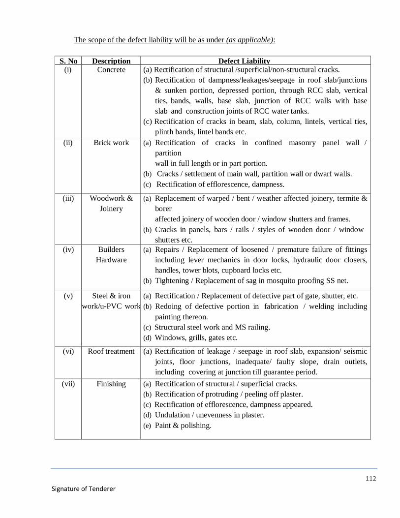
112
Signature of Tenderer
The scope of the defect liability will be as under (as applicable):
S. No Description Defect Liability (i) Concrete (a) Rectification of structural /superficial/non-structural cracks.
(b) Rectification of dampness/leakages/seepage in roof slab/junctions
& sunken portion, depressed portion, through RCC slab, vertical
ties, bands, walls, base slab, junction of RCC walls with base
slab and construction joints of RCC water tanks.
(c) Rectification of cracks in beam, slab, column, lintels, vertical ties,
plinth bands, lintel bands etc.
(ii) Brick work (a) Rectification of cracks in confined masonry panel wall /
partition
wall in full length or in part portion.
(b) Cracks / settlement of main wall, partition wall or dwarf walls.
(c) Rectification of efflorescence, dampness.
(iii) Woodwork &
Joinery
(a) Replacement of warped / bent / weather affected joinery, termite &
borer
affected joinery of wooden door / window shutters and frames.
(b) Cracks in panels, bars / rails / styles of wooden door / window
shutters etc.
(iv) Builders
Hardware
(a) Repairs / Replacement of loosened / premature failure of fittings
including lever mechanics in door locks, hydraulic door closers,
handles, tower blots, cupboard locks etc.
(b) Tightening / Replacement of sag in mosquito proofing SS net.
(v) Steel & iron
work/u-PVC work
(a) Rectification / Replacement of defective part of gate, shutter, etc.
(b) Redoing of defective portion in fabrication / welding including
painting thereon.
(c) Structural steel work and MS railing.
(d) Windows, grills, gates etc.
(vi) Roof treatment (a) Rectification of leakage / seepage in roof slab, expansion/ seismic
joints, floor junctions, inadequate/ faulty slope, drain outlets,
including covering at junction till guarantee period.
(vii) Finishing (a) Rectification of structural / superficial cracks.
(b) Rectification of protruding / peeling off plaster.
(c) Rectification of efflorescence, dampness appeared.
(d) Undulation / unevenness in plaster.
(e) Paint & polishing.
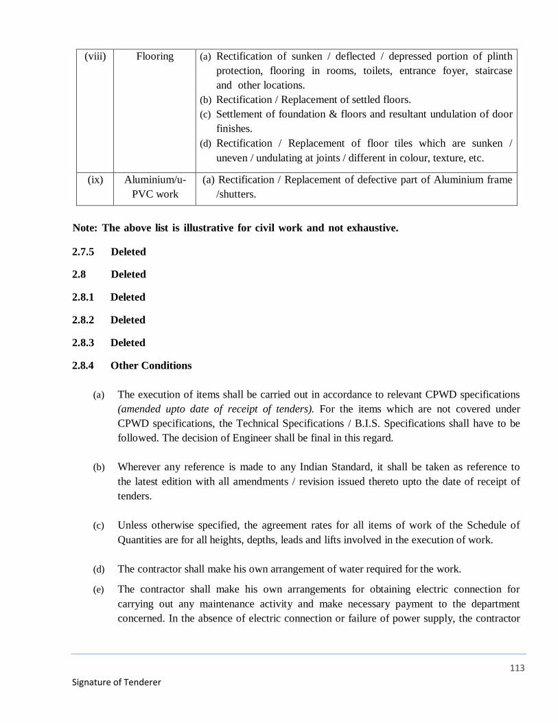
113
Signature of Tenderer
(viii) Flooring (a) Rectification of sunken / deflected / depressed portion of plinth
protection, flooring in rooms, toilets, entrance foyer, staircase
and other locations.
(b) Rectification / Replacement of settled floors.
(c) Settlement of foundation & floors and resultant undulation of door
finishes.
(d) Rectification / Replacement of floor tiles which are sunken /
uneven / undulating at joints / different in colour, texture, etc.
(ix) Aluminium/u-
PVC work
(a) Rectification / Replacement of defective part of Aluminium frame
/shutters.
Note: The above list is illustrative for civil work and not exhaustive.
2.7.5 Deleted
2.8 Deleted
2.8.1 Deleted
2.8.2 Deleted
2.8.3 Deleted
2.8.4 Other Conditions
(a) The execution of items shall be carried out in accordance to relevant CPWD specifications
(amended upto date of receipt of tenders). For the items which are not covered under
CPWD specifications, the Technical Specifications / B.I.S. Specifications shall have to be
followed. The decision of Engineer shall be final in this regard.
(b) Wherever any reference is made to any Indian Standard, it shall be taken as reference to
the latest edition with all amendments / revision issued thereto upto the date of receipt of
tenders.
(c) Unless otherwise specified, the agreement rates for all items of work of the Schedule of
Quantities are for all heights, depths, leads and lifts involved in the execution of work.
(d) The contractor shall make his own arrangement of water required for the work.
(e) The contractor shall make his own arrangements for obtaining electric connection for
carrying out any maintenance activity and make necessary payment to the department
concerned. In the absence of electric connection or failure of power supply, the contractor
114
Signature of Tenderer
shall make his own arrangements of generators.
(f) Other agencies working at site will also simultaneously execute the work. The contractor
shall offer necessary cooperation to other agencies wherever required.
(g) On account of security consideration, there could be some restrictions on the working
hours, movement of vehicles for transportation of materials, etc. The contractor shall be
bound to follow all such restrictions and adjust the programmes for execution of works
accordingly.
(h) The work shall be carried out in a manner complying in all respects with the requirements
of any prevalent statutory laws enacted either by Central Govt. as well as State
Govt./Authority.
(i) Any malba / building rubbish generated is to be removed from the site within 24 hours and
to be stacked at a pre-designated place. The malba / building rubbish so stacked shall be
disposed off as soon as one truck load is accumulated (approx 5 cum) from such
designated place.
(j) This malba / building rubbish has to be disposed off to the dumping ground as approved
by the Engineer in consultation with DFCCIL. The rates quoted by the contractor are
inclusive of all operations, labour, leads and lifts from site of work to the dumping
ground.
(k) Maintenance Engineer/Supervisor shall carry mobile telephone (s) to enable the Engineer-
in-Charge to have easy and quick communication. Nothing extra shall be paid to the
contractor on this account and his quoted rates for various items under this contract will
be inclusive of this obligation.
(l) The replaced materials used shall have same or richer specifications to the original
materials and compatible to the work.
(m) The staff employed by the contractor should be well behaved and any complaint of
misbehaviour shall be taken very seriously and such staff will have to be removed by the
contractor immediately from the site.
(n) The dismantled materials shall be taken away and disposed off by the contractor at his
cost. Nothing extra shall be paid / recovered on account of this.
(o) The contractor shall make all safety arrangements required for the labour engaged by him
at his cost. All consequences due to negligence on behalf of security / safety or otherwise
115
Signature of Tenderer
shall be on the contractor. The department shall not be responsible for any mishap, injury,
accident or death of the contractor’s staff. No claim in this regard shall be entertained /
accepted by the department.
(p) Contractor shall be fully responsible for any damages caused to government property or
allottee’s property by him or his labour in carrying out the work and shall be rectified by
the contractor at his own cost.
(q) Chases, holes, etc. shall be done using power operated tools.
2.9 Safety measures
2.9.1 The issue of construction safety & standards has gained utmost importance in recent times.
This subject is to be dealt with, in an overall manner with an approach to developing and
establishment a safety culture at work sites. Broadly, its components are:
2.9.1.1 Creating an awareness
2.9.1.2 Education
2.9.1.3 Training
2.9.1.4 Implementation
2.9.1.5 Enforcement measures
All workers of contractor and associate agencies, invariably and at all the times, must follow
all safety norms, adopt safe construction practices and use all required safety gadgets in
their working, throughout the project duration.
2.9.2 The contractor will employ a Safety Engineer. He shall be primarily responsible for
developing safety programs, training, implementation and propagating safety culture.
2.9.3 The contractor shall issue Photo Identity Cards with unique numbers containing salient
information of workers. Further the contractor shall establish a Time Office at the entry to
demarcate area of site. The Time Office shall maintain a computerized record of all the
workers allowed entry / working inside the demarcated area.
2.9.4 Formation of Safety Monitoring Committee: The contractor within 30 days of start of work
shall submit the names of Safety Engineer to the Engineer/DFCCIL who shall notify a
monitoring committee consisting of authorized representatives of the contractor, associate
agencies (if any), DFCCIL. The mandate of this monitoring committee will be to monitor and
achieve the objectives of construction safety continuously, progressively and through
116
Signature of Tenderer
affirmative action and to inculcate the safety culture among all stake holders. This
committee will oversee implementation of safety program over the entire construction
period.
2.9.5 Training and Awareness:
a. Training: The training shall be in two phases- first initial training and then periodic
training / refresher workshop.
b. Initial training: All the workers shall have to undergo a training program of 16 hrs (8 hrs
for 2 days) and to be declared satisfactorily trained by the Safety Manager before they are
allowed to work on site.
c. Orientation Program: An orientation program shall be arranged for all people (other
than workers) who normally work at or visit the site.
d. Workshops: Refresher workshops shall be arranged for one day in every three months for
all the workers on site.
e. Advance training: For workers involved in high risk activities (to be identified by the
Safety Monitoring Committee) a refresher workshop / training shall be kept once a
month.
f. The training modules shall be designed by the Safety Manager and approved by the
Safety monitoring committee.
g. Training Methodology: The training methodology shall include both classroom and
practical demonstration with audio visual techniques. For greater impact,
demonstration with dummies will be done to highlight hazards of not following safe
practices. The training shall be imparted in vernacular language and may include
means such as songs, theatre, puppetry etc. for better appreciation and assimilation by
workers.
h. Implementation:
The basic responsibility of implementation of safe practices shall be that of the
safety manager and safety supervisors of the contractor at the first level and
Engineer and DFCCIL on second level. The basic approach of implementation
should be towards voluntary acceptability of safe practices by all stake holders.
The safety arrangement made by the contractor shall be open to inspection by the
117
Signature of Tenderer
safety officer or any other representative appointed by Engineer/DFCCIL and the
observation made by him shall be complied with by the contractor.
2.9.6 Enforcement: The safety team of the contractor and Engineer are entrusted with
enforcement of safe practices. If safety program is not followed (as assessed by
Engineer/DFCCIL) then suitable actions shall be taken as per GCC.
a. No person shall be allowed to enter the demarcated area without adequate safety
gadgets (as per occupation / purpose of visit).
b. In case the contractor / subcontractor do not impart training, the same shall be provided
by DFCCIL through an accredited agency. Twice the amount of fee for such training
shall be deducted from the contractor. A display board shall be kept at site which would
list the names of workers / teams and agencies following safety program in the best
manner. This would be updated weekly.
c. During training and workshops, the names of persons / teams / agencies that are best
following safety program shall be announced and they shall be felicitated.
d. On completion of the work, shields for best person / team / agencies safety program in
different categories shall be awarded.
2.10 SECURITY
2.10.1 Contractor shall take all measures and precautions relating to security of the construction site.
He shall barricade the construction site / designated area of construction through the
barriers and as approved by the Engineer. No material shall be stored / dumped outside
the designated area.
2.10.2 The movement of the construction vehicles and the labours shall be restricted to the
designated routes which will be decided by the Engineer/DFCCIL.
2.10.3 All the vehicles carrying the material to the work site shall be subject to check and entries to
be made at the gates. No material shall be taken out without proper gate pass.
2.10.4 Any labour engaged by the contractor shall be in possession of photo ID card failing which
they are liable to be disengaged from the work and shall not be allowed to enter into the
construction site.
2.10.5 In case of any nuisance caused by activates attributed to contractors’ staff, workmen and
118
Signature of Tenderer
movement of vehicle, and reported to Engineer /DFCCIL, a suitable act ion will be
taken by the Engineer /DFCCIL.
2.10.6 The movement of the labour shall be restricted to the barricaded work site area only.
2.11 3rd PARTY QUALITY ASSURANCE
2.11.1 In order to achieve high standards of materials, workmanship and overall quality of the
execution, an agency engaged by DFCCIL will carry out Third Party Inspections as part
of ‘Third Party Quality Assurance’. This agency will carry out the checks of the quality
assurance procedures followed at site, take samples of the materials for independent testing
and check the workmanship of the works carried out. The contractor shall extend full co-
operation to the TPQA agency in facilitating the inspections and collection of samples and
regulate the execution stages with regards to the hold and witness points which shall be
strictly adhered to by the contractor. The next stage work shall not be undertaken at the hold
point stage and work shall be done in presence of the TPQA representative at the witness
stage. The contractor shall be required to co-operate with agency in carrying out various
activities including documentation at no extra time and cost to the owner. In case of any
adverse findings by the TPQA agency, the contractor shall do the needful rectifications to
the entire satisfaction of the TPQA agency and DFCCIL. If contractor fails to rectify
the defects of the serious nature within a reasonable time frame, no further payment
shall be made.
If work is stopped due to non- rectification of defects and delay occurs on this account,
no relief in completion of mile stone by way of grant of EOT or any other relaxation be
given.
2.12 CONSTRUCTION VEHICLES TYRE WASHING FACILITIES
All the vehicles leaving the site shall be loaded in such a manner that the excavated
materials, mud or debris will not be deposited on roads. All such loads shall be covered or
protected to prevent dust being emitted. The wheels of all vehicles shall be washed properly
before leaving the site to avoid the deposition of mud and debris on the roads. The
contractor shall provide a wash pit and a wheel washing facility with high pressure water jets
for this purpose. Also, the contractor shall make necessary arrangements for sweeping and
removal of mud from roads if it is deposited even after washing of wheels of vehicles leaving
site. Nothing extra shall be paid for providing and maintaining this facility.
2.13 BARRICADING OF SITE
The contractor shall make adequate arrangement for new barricading as directed by the
Engineer to cover the entire construction site including all T&P and materials. The
requirement of providing and fixing new barricading at site shall be decided as per the
direction and approval of Engineer. The barricading shall be provided continuously during
119
Signature of Tenderer
the execution of the entire work till completion and shall not be removed at any stage
without prior approval of the Engineer. The barricading shall be provided and shall be
the property of the contractor after completion of the work.
2.14 WATER SUPPLY
Contractor shall be responsible for the arrangement to obtain supply of water necessary for
the works at his own cost.
2.15 ELECTRIC SUPPLY
Contractor shall be responsible for the arrangement to obtain supply of electric power
necessary for the works at his own cost.
2.16 COMPLIANCE TO ENVIRONMENTAL LAWS
The contractor shall comply the directives of Hon’ble National Green Tribunal dated
04.12.2014 & 10.04.2015 and EIA Guidance Manual issued in February 2010 and
Construction & Demolition Waste Management Rules, 2016. The compliance of the
contractor shall not be limited to the following:
1. The contractor shall not store/dump construction material or debris on metalled road.
2. The contractor shall get prior approval from Engineer for the area where the construction
material or debris can be stored beyond the metalled road. This area shall not cause any
obstruction to the free flow of traffic/inconvenience to the pedestrians. It should be
ensured by the contractor that no accidents occur on account of such permissible
storage.
3. The contractor shall take appropriate protection measures like raising wind breakers of
appropriate height on all sides of the plot/area using CGI sheets or plastic and/or other
similar material to ensure that no construction material dust fly outside the plot area.
4. The contractor shall ensure that all the trucks or vehicles of any kind which are used for
construction purposes/or are carrying construction material like cement, sand and other
allied material are fully covered. The contractor shall take every necessary precautions
that the vehicle are properly cleaned and dust free to ensure that enroute their destination,
the dust, sand or any other particles are not released in air/contaminate air.
5. The contractor shall provide mask to every worker working on the construction site and
involved in loading, unloading and carriage of construction material and construction
debris to prevent inhalation of dust particles.
6. The contractor shall provide all medical help, investigation and treatment to the workers
120
Signature of Tenderer
involved in the construction of building and carry of construction material and debris
relatable to dust emission.
7. The contractor shall ensure that C&D waste is transported to the approved C&D waste
site of local authority only as per Construction & Demolition Waste Management Rules,
2016 and due record shall be maintained by the contractor.
8. The contractor shall compulsorily use jet in grinding and stone cutting.
9. The contractor shall comply all the preventive and protective environmental steps as
stated in the MoEF Guidelines, 2010.
10. The contractor shall carry out On-Road-Inspection for black smoke generating
machinery. The contractor shall use cleaner fuel.
11. The contractor shall ensure that the DG sets comply emission norms notified by MoEF.
12. The contractor shall use vehicles having pollution under control certificate. The
emissions can be reduced by a large extent by reducing the speed of a vehicle to 20
kmph. Speed bumps shall be used to ensure speed reduction. In cases where speed
reduction cannot effectively reduce fugitive dust, the contractor shall divert traffic to
nearby paved areas.
13. The contractor shall ensure that the construction material is covered by tarpaulin. The
contractor shall take all other precaution to ensure that no dust particles are permitted to
pollute air quality as a result of such storage.
14. No extra payment will be made for operation/activity mentioned at Sl. No. 1 to 13 above.
2.17 Deleted
2.18 NOTES
2.18.1 Deleted.
2.18.2 Tenderer is advised to visit the site before submitting their bid. The site may have bushes
and vegetation, etc. Nothing extra shall be payable on account of cleaning of site. The
contractor must plan his activities accordingly so as to effectively utilize the cutting and
filling of earth in nearest possible locations.
121
Signature of Tenderer
PART-I
CHAPTER-V
SECTION-3
ADDITIONAL SPECIAL CONDITIONS OF CONTRACT
3. GENERAL
3.1 Where there is any conflict between the various documents in the contract, the following
order of priority shall be followed i.e. a document appearing earlier shall override the
document appearing subsequently. However, the decision of Engineer would be final &
binding in this regard.
Order of Priority of Documents:
a. Letter of Acceptance (LOA)
b. Schedule of items, Rates & Quantities.
c. Special Conditions of Contract.
d. Technical Specifications as given in tender documents.
e. Drawings, if any.
f. General Conditions of Contract.
g. Relevant BIS Codes.
Note: Unless otherwise specified, CPWD Specifications 2009 Volume I & II with
corrections slips till the last date of tender submission shall be followed in general. Any
additional item of work, if taken up subsequently, shall also conform to the relevant
CPWD Specifications mentioned above (if available).
3.1.1 The work shall be carried out in accordance with the Architectural drawings and structural
drawings, to be issued from time to time, by the Engineer. Before commencement of any
item of work, the contractor shall correlate all the relevant architectural and structural
drawings issued for the work and satisfy himself that the information available from there
is complete and unambiguous. The discrepancy, if any, shall be brought to the notice of
the Engineer before execution of the work. The contractor alone shall be responsible for
any loss or damage occurring by the commencement of work on the basis of any
erroneous and or incomplete information.
122
Signature of Tenderer
3.1.2 The contractor shall be responsible for the watch and ward / guard of the buildings, till the
building is physically handed over to the DFCCIL. No extra payment shall be made
on this account.
3.1.3 For works below ground level, the contractor shall keep that area free from water. If,
dewatering or bailing out of water is required, the contractor shall do it at his cost and
nothing extra shall be paid except otherwise provided in the items of schedule of quantities.
3.1.4 Results of sub-surface investigations conducted at site are indicated in extracts of the soil
investigation report (available in DFCCIL Office). This information about the soil and sub-
soil water conditions is indicative and is being provided, in good faith, for guidance only
and the tenderer is advised to obtain details directly as may be considered necessary by
him before quoting rates in the tender. No claim whatsoever on account of any
discrepancy between the sub- surface strata conditions that may be actually encountered at
the time of execution of the work and those given in these tender documents, in-accuracy
or interpretation thereof shall be entertained from the Contractor under any circumstances.
The ground water table is a variable condition and the information given in the report is
only indicative and it may vary from time to time.
3.1.5 Excavated earth shall be property of DFCCIL and shall not be disposed off without
approval of Engineer. Any legal or financial implications resulting out of disposal of earth
shall be sole responsibility of the contractor.
3.1.6 The Contractor shall make all necessary arrangements for protecting from rains, fog or
likewise extreme weather conditions, the work already executed and for carrying out the
further work, during monsoon including providing and fixing temporary shelters,
protections etc. Nothing extra shall be payable on this account. Also, no claims for
hindrance shall be entertained on this account.
3.1.7 In case of flooding of site on account of rain or any other cause and any consequent
damage, whatsoever, no claim financially or otherwise shall be entertained not withstanding
any other provisions elsewhere in the contract agreement. Also, the Contractor shall make
good, at his own cost, the damages caused, if any. Further, no claims for hindrance shall be
entertained on this account.
3.1.8 The contractor will take reasonable precautions to prevent his workmen and employees from
removing and damaging any flora (plant/vegetation) from the project area.
3.1.9 Emergency Work:
In the event of any action or failure occurring in on or about the work or arising out of or in
connection with the construction, completion or maintenance of the work which in the
Engineer opinion requires immediate attention, Engineer may by its own workmen or other
123
Signature of Tenderer
agency execute or partly execute the necessary work or carry out repairs if the Engineer
considers that the contractor is not in a position to do in time and to charge the cost thereof to
the contractor as determined by the Engineer.
3.1.10 Protection & Care of Works:
a. The works are to be protected as asked by the Engineer. Protection is required for all
hazardous works and during installation, testing & commissioning of work. The cost of
safety measures & other gadgets etc. shall be deemed to be included in the quoted rates
and nothing extra shall be paid for the same.
b. Care of the building:
(i) Care shall be taken by the contractor during execution of the work to avoid damage to the
building and adjacent buildings.
(ii) They shall also be responsible for repairing all such damages and restoring the same to the
original finish at their cost.
(iii) They shall also remove all unwanted and waste materials arising out of the execution of
work from the site from time to time.
3.1.11 Handing Over
a. On completion of all items of work as per contract, contractor shall hand over the works to
joint taking over by client & Engineer. The handing over of the completed works to Engineer
shall be the responsibility of the contractor. The handing over will be treated as final only
when the same is taken over by the Engineer/Client officially in writing. The defect liability
period will commence from the date of handing over to the Engineer. The process of handing
over shall be as under:-
One month in advance of the stipulated date of completion, joint inspection shall be carried
out with contractor and Engineer’s representatives and all the defects, deficiencies shall be
noted and a time bound programme to be made for rectifying/making good all the defects and
deficiencies. The contractor shall remove at his own cost all surplus materials, debris, material
waster, labour hutments before handing over. If it is felt that the contractor is not responding
to rectify the defects urgently and the Engineer is suffering in using the assets created due to
default of the contract, Engineer shall be entitled to get the defects rectified at the risk and cost
of the contractor any time after expiry of 24 hours notice issued to the contractor.
124
Signature of Tenderer
3.2 TOOLS AND PLANTS
3.2.1 The bidder should arrange construction equipments required for the proper and timely
execution of the work. Nothing extra shall be paid on this account.
3.2.2 No tools and plants including any special T&P etc. shall be supplied by the Department and
the contractor shall have to make his own arrangements at his own cost. No claim of
hindrance (or any other claim) shall be entertained on this account.
3.2.3 The contractor shall do proper sequencing of the various activities by suitably staggering the
activities within various pockets in the plot so as to achieve early completion. The agency
may deploy adequate equipment, machinery and labour as required for the completion of
the entire work within the stipulated period specified. Also ancillary facilities shall be
provided by contractor commensurate with requirement to complete the entire work within
the stipulated period. Nothing extra shall be payable on this account. Adequate number/sets
of equipment in working condition, along with adequate stand-by arrangements, shall be
deployed during entire construction period. It shall be ensured by the Contractor that all the
equipment, Tools & Plants, machineries etc. provided by him are maintained in proper
working conditions at all times during the progress of the work and till the completion of
the work. Further, all the constructional tools, plants, equipment and machineries provided
by the contractor, on site of work or his work shop for this work, shall be exclusively
intended for use in the construction of this work and they shall not be shifted / removed
from site without the permission of the Engineer.
3.3 ROYALTY
3.3.1 Royalty at the prevalent rates shall be paid by the contractor or the RMC supplier as per the
terms of supply between them, on all materials such as boulders, metals, all sizes stone
aggregates, brick aggregates, coarse and fine sand, moorum, river sand, gravels and bajri
etc. collected by him for the execution of the work, directly to the revenue authority of the
state government concerned. Further, contractor needs to submit proof of submission of full
royalty to the state government or local authority. Nothing extra shall be payable on
this account.
3.4 PRESERVATION AND CONSERVATION MEASURES
3.4.1 Existing drains, pipes, cables, over-head wires, sewer lines, water lines and similar services
encountered in the course of the execution of work shall be protected against the damage
by the contractor, at his own expense, for which nothing is payable. The contractor shall not
125
Signature of Tenderer
store materials or otherwise occupy any part of the site in a manner likely to hinder the
operation of such services.
3.4.2 All fossils, coins, articles of value of antiquity, structures and other remains or things of
geological or archaeological interest discovered on project location during excavation/
construction shall be the property of the Government, and shall be dealt with as per
provisions of the relevant legislation. The contractor will take reasonable precaution to
prevent his workmen or any other persons from removing and damaging any such article or
thing. He will, immediately upon discovery thereof and before removal acquaint the
Engineer of such discovery and carry out the official instructions of Engineer for dealing
with the same, till then, all work shall be carried out in a way so as not to disturb/ damage
such article or thing.
3.5 RESPONSIBILITY
3.5.1 The Contractor shall keep himself fully informed of all relevant acts and laws of the Central
& State Governments, orders, decrees of statutory bodies, tribunals having any jurisdiction
or authority, which in any manner may affect those engaged or employed and anything
related to carrying out the work. All the rules & regulations and bye-laws laid down
by District Collector /Noida Authority and any other statutory bodies shall be adhered to,
by the contractor, during the execution of work. The Contractor shall also adhere to all
traffic restrictions notified by the local authorities. The water charges (for municipal water
connection as well as tanker water) shall be borne by the contractor. Also, if the
contractor obtains water connection for the drinking purposes from the municipal
authorities or any other statutory body, the consequent sewerage charges shall be borne
by the contractor. All statutory taxes, levies, charges (including water and sewerage
charges, charges for temporary service connections and / or any other charges) payable to
such authorities for carrying out the work, shall be borne by the Contractor. The
Contractor shall arrange to give all notices as required by any statutory / regulatory authority
and shall pay to such authority all the fees that is required to be paid for the execution of
work. He shall protect and indemnify the DFCCIL and its officials & employees against
any claim and /or liability arising out of violations of any such laws, ordinances, orders,
decrees, by himself or by his employees or his authorized representatives. Nothing extra
shall be payable on these accounts.
3.5.2 The fee payable to statutory authorities for obtaining the various permanent service
connections and Building Use Certificate for the building shall be borne by the DFCCIL.
The contractor shall assume all liability, financial or otherwise in connection with this
contract and shall protect and indemnify DFCCIL from any and all damages and claims
126
Signature of Tenderer
that may arise on any account. The Contractor shall indemnify against all claims in
respect of patent rights, royalties, design, trademarks of name or other protected rights,
damages to adjacent buildings, roads or members of public, in course of execution of
work or any other reasons whatsoever, and shall himself defend all actions arising from
such claims and shall indemnify the DFCCIL in all respect from such actions, costs
and expenses. Nothing extra shall be payable on this account.
3.5.3 The contractor shall keep himself fully informed of all acts and laws of the Central
Government and Government of U.P., all local bye laws, ordinances, rules and regulations
and all orders and decree of bodies or, tribunals having any jurisdiction or authority which in
any manner affect those engaged or employed on the work or which in any way affect the
conduct of the works. Contractor shall at all times, observe and comply with all such laws,
ordinances, rules, regulations, orders and decrees, and shall give all notices and pay out of
his own money any fees or charges to which he may be liable. He shall protect and
indemnify the DFCCIL and its officers and employees against any claim or liability
arising out of violations of any such law, ordinances, legislations, order or decree, whether
by himself or by his employees & authorized representatives.
3.6 CO-OPERATION WITH OTHER CONTRACTORS/SPECIALIZED
AGENCIES/SUB-CONTRACTORS
3.6.1 The contractor shall take all necessary precautions to prevent any nuisance or
inconvenience to the owners, tenants or occupants of the adjacent properties and to the
public in general .The Contractor shall take all care, as not to damage any other adjacent
property or other services running adjacent to the plot. If any damage is done, the same
shall be made good by the contractor at his own cost and to the entire satisfaction of the
Engineer. The contractor shall use such methodology and equipment for execution of the
work, so as to cause minimum environmental pollution of any kind during construction,
to have minimum construction time and minimum inconvenience to road users and to the
occupants of the buildings on the adjacent plot and public in general, etc. He shall make
good at his own cost and to the entire satisfaction of the Engineer any damage to roads,
paths, cross drainage works or public or private property whatsoever caused, due to the
execution of the work or by traffic brought thereon, by the Contractor. Further, the
contractor shall take all precautions to abide by the environmental related restrictions
imposed by U.P. state Pollution control board, Govt. of U.P. as well as prevent any
pollution of streams, ravines, river bed and waterways. All waste or superfluous
materials shall be transported by the Contractor, entirely to the satisfaction of the Engineer.
Utmost care shall be taken to keep the noise level to the barest minimum so that no
disturbance as far as possible is caused to the occupants / users of adjoining buildings. No
claim what so ever on account of site constraints mentioned above or any other site
constraints, such as distance from Noida city as approximately 20 km, lack of public
transport, inadequate availability of skilled, semi-skilled or unskilled workers in the near
vicinity, non-availability of construction machinery spare parts and any other constraints
not specifically stated here, shall be entertained from the contractor. Therefore, the
127
Signature of Tenderer
Tenderers are advised to visit site and get first-hand information of site constraints.
Accordingly, they should quote their tenders. Nothing extra shall be payable on this
account.
3.6.2 The contractor shall cooperate with and provide the facilities to the sub-contractors and
other agencies working at site for smooth execution of the work. The contractor shall
indemnify the DFCCIL against any claim(s) arising out of such disputes. The contractor
shall :
a. Allow use of scaffolding, toilets, sheds etc.
b. Properly co-ordinate their work with the work of other Contractors.
c. Provide control lines and benchmarks to his Sub-Contractors and the other Contractors.
d. Provide electricity and water at mutually agreed rates.
e. Provide hoist and crane facilities for lifting material at mutually agreed rates.
f. Co-ordinate with other contractors for leaving inserts, making chases, alignment of
services etc. at site.
g. Adjust work schedule and site activities in consultation with the Engineer and other
contractors to suit the overall schedule completion.
h. Resolve the disputes with other contractors / sub-contractors amicably and the Engineer
shall not be made intermediary or arbitrator.
3.6.3 The work should be planned in a systematic manner so as to ensure proper co-ordination of
various disciplines
3.6.4 The contractor shall leave recesses, holes, openings trenches etc. as may be required for
the related works and nothing extra shall be payable on this account.
3.6.5 The contractor shall conduct his work, so as not to interfere with or hinder the progress or
completion of the work being performed by other contractor(s) or by the Engineer and shall
as far as possible arrange his work and shall place and dispose of the materials being used
or removed so as not to interfere with the operations of other contractor or he shall
arrange his work with that of the others in an acceptable and in a proper co-ordination
manner and shall perform it in proper sequence to the complete satisfaction of others.
128
Signature of Tenderer
3.6.6 Specialized Agencies
The tenderer must associate with himself, agencies of the appropriate eligibility to tender for
each of specialized nature of items / work. Such works shall be got executed only through
associated agencies specialized in these fields.
It shall be the responsibility of main contractor to sort out any dispute / litigation with
the Specialized Agencies without any time & cost overrun to the DFCCIL. The main
contractor shall be solely responsible for settling any dispute / litigation arising out of his
agreement with the Specialized Agencies. The contractor shall ensure that the work shall
not suffer on account of litigation/ dispute between him and the specialized agencies / sub-
contractor(s). No claim of hindrance in the work shall be entertained from the Contractor on
this account. No extension of time shall be granted and no claim what so ever, of any kind,
shall be entertained from the Contractor on account of delay attributable to the
selection/rejection of the Specialized Agencies.
3.7 RATES 3.7.1 The rates quoted by the contractor are deemed to be inclusive of site clearance, setting out
work, profile, setting lay out on ground, establishment of reference bench mark(s), installing
various signage, taking spot levels, survey with total station, construction of all safety and
protection devices, compulsory use of helmet and safety shoes, and other appropriate
safety gadgets by workers, imparting continuous training for all the workers, barriers,
preparatory works, construction of clean, hygienic and well ventilated workers housings in
sufficient numbers working during monsoon or odd season, working beyond normal hours,
working at all depths, height, lead, lift, levels and location etc. and any other unforeseen
but essential incidental works required to complete this work. Nothing extra shall be
payable on this account and no extension of time for completion of work shall be granted
on these accounts.
3.7.2 The rates quoted by the tenderer shall be inclusive of all taxes and duties, except GST.
GST as applicable shall be paid extra on the accepted rates mentioned in Schedule- II. If any
cost implication to DFCCIL is occurred on GST account because of Contractor’s default in
filing of GST returns such as no GST number, wrong GST number, mismatch of GST
number etc. , the same shall be recovered from the Contractor’s bill or any other pending/
future bill. Price variation on Schedule-II (Civil works) will be applicable as per the clause
mentioned in GCC. 3.7.3 No foreign exchange shall be made available by the DFCCIL for importing (purchase) of
equipment, plants, machinery, materials of any kind or any other items required to be
carried out during execution of the work. No delay and no claim of any kind shall
be entertained from the Contractor, on account of variation in the foreign exchange rate.
3.7.4 All ancillary and incidental facilities required for execution of work like labour camp,
stores, fabrication yard, offices for Contractor, watch and ward, temporary ramp
required to be made for working at the basement level, temporary structure for plants
and machineries, water storage tanks, installation and consumption charges of temporary
electricity, telephone, water etc. required for execution of the work, liaison and pursuing
129
Signature of Tenderer
for obtaining various No Objection Certificates, completion certificates from local bodies
etc., protection works, testing facilities / laboratory at site of work, facilities for all field
tests and for taking samples etc. during execution or any other activity which is necessary
(for execution of work and as directed by Engineer), shall be deemed to be included in
rates quoted by the Contractor, for various items in the schedule of quantities.
Nothing extra shall be payable on these accounts. Before start of the work, the
Contractor shall submit to the Engineer, a site / construction yard layout, specifying areas
for construction, site office, positioning of machinery, material yard, cement and other
storage, steel fabrication yard, site laboratory, water tank, etc. DFCCIL shall provide
rent free piece of land for construction of these facilities at construction site for the
duration of this work.
3.7.5 For completing the work in time, the contractor might be required to work in two or
more shifts (including night shifts). No claim whatsoever shall be entertained on this
account, not with-standing the fact that the contractor may have to pay extra amounts for
any reason, to the labourers and other staff engaged directly or indirectly on the work
according to the provisions of the labour and other statutory bodies regulations and the
agreement entered upon by the contractor with them.
3.7.6 All material shall only be brought at site as per program finalized with the Engineer.
Any pre-delivery of the material not required for immediate consumption shall not be
accepted and thus not paid for.
3.7.7 Deleted
3.8 SAFETY PRACTICES
3.8.1 WARNING / CAUTION BOARDS: All temporary warning / caution boards / glow
signage display such as "Construction Work in Progress“, "Keep Away", “No Parking”,
Diversions & protective Barricades etc. shall be provided and displayed during day time
by the Contractor, wherever required and as directed by the Engineer. These glow
signages and red lights shall be suitably illuminated during night also. The Contractor
shall be solely responsible for damage and accident caused, if any, due to negligence on his
part. Also he shall ensure that no hindrance, as far as possible, is caused to general traffic
during execution of the work. This signage shall be dismantled & taken away by the
Contractor after the completion of work, only after approval of the Engineer. Nothing
extra shall be payable on this account.
3.8.2 SIGN BOARDS: The contractor shall provide and erect a display board of size and shape

130
Signature of Tenderer
as required and paint over it, in a legible and workman like manner, the details about the
salient features of the project, as required by the Engineer. The Contractor shall fabricate
and put up a sign board in an approved location and to an approved design indicating
name of the project, client / owner, architects, structural consultants etc. besides providing
space for names of other Contractors, Sub-Contractors and specialized agencies. Nothing
extra shall be payable on this account.
3.8.3 Necessary protective and safety equipment shall be provided to the Site Engineer,
Supervisory staff, labour and technical staff of the contractor by the contractor at his own
cost and to be used at site.
3.8.4 No inflammable materials including P.O.L shall be allowed to be stored in huge quantity at
site. Only limited quantity of P.O.L may be allowed to be stored at site subject to the
compliance of all rules / instructions issued by the relevant authorities and as per the
direction of Engineer in this regard. Also all precautions and safety measures shall be
taken by the contractor for safe handling of the P.O.L products stored at site. All
consequences on account of unsafe handling of P.O.L shall be borne by the Contractor.
3.9 QUALITY ASSURANCE
3.9.1 Quality of work is of paramount importance. Contractor shall have to engage well-
experienced skilled labour and deploy modern T&P and other equipment to execute the
work. Many items like exposed finish form work, specialized flooring work, Polysulphide /
P.U. sealant and backer rod fixing in expansion joints, factory made door- window
shutters, proper slope maintaining in toilet units, sanitary- water supply installation,
textured finishing, grit plastering with aluminium channel insertions, water proofing
treatment, Extruded Polystyrene insulation boards, façade works and chemical treatment
in toilet drops will specially require engagement of skilled workers having experience
particularly in execution of such items.
3.9.2 The contractor shall ensure quality construction in a planned and time bound manner. Any
sub-standard material / work beyond set out tolerance limit shall be summarily rejected by
the Engineer & contractor shall be bound to replace / remove such sub-standard / defective
work immediately. If any material, even though approved by Engineer is found defective or
not conforming to specifications shall be replaced / removed by the contractor at his
own risk & cost.
3.9.3 Deleted
3.9.4 The contractor shall submit, a detailed and complete method statement for the execution,
testing and Quality Assurance, of such items of works, as directed by the Engineer. All the
materials to be used in the work, to give the finished work complete in all respects, shall
comply with the requirements of the specifications and shall pass all the tests required as
per specifications as applicable or such specifications / standards as directed by the
Engineer. However, keeping the Quality Assurance in mind, the Contractor shall submit, on
131
Signature of Tenderer
request from the Engineer, his own Quality Assurance procedures for basic materials and
such items, to be followed during the execution of the work, for approval of the Engineer.
3.9.5 All materials and fittings brought by the contractor to the site for use shall conform to the
samples approved by the Engineer which shall be preserved till the completion of the work.
If a particular brand of material is specified in the item of work in Schedule of Quantity,
the same shall be used after getting the same approved from Engineer. Wherever brand /
quality of material is not specified in the item of work, the contractor shall submit the
samples as per suggested list of brand names given in the tender document / SCC for
approval of Engineer. For all other items, materials and fittings of ISI Marked shall be
used with the approval of Engineer. Wherever ISI Marked material / fittings are not
available, the contractor shall submit samples of materials / fittings manufactured by
firms of repute conforming to relevant specifications or IS codes and use the same only
after getting the approval of Engineer.
3.9.6 The contractor shall procure and provide all the materials from the manufacturers / suppliers
as per the list attached with the tender documents/SCC, as per the item description of the
work. The equivalent brand for any item shall be permitted to be used in the work, only
after approval of Engineer/Employer. No claim, whatsoever, of any kind shall be
entertained from the contractor on this account and Nothing extra shall be payable on this
account.
3.9.7 All materials whether obtained from Govt. stores or otherwise shall be got checked by the
Engineer or his authorized supervisory staff on receipt of the same at site before use.
3.9.8 The tests, as necessary, shall be conducted in the laboratory approved by the Engineer. The
samples shall be taken for carrying out all or any of the tests stipulated in the specifications
and as directed by the Engineer or his authorized representative.
3.9.9 All the registers of tests carried out at Construction Site or in outside laboratories and all
material at site (MAS) registers including cement register shall be maintained by the
contractor which shall be issued to the contractor by Engineer. All the entries in the
registers will be made by the designated Engineering Staff of the contractor and same
should be regularly reviewed by Engineer/Employer. Contractor shall be responsible for
safe custody of all the test registers.
3.9.10 The contractor shall at his own risk and cost make all arrangements and shall provide all
such facilities including material and labour, the Engineer may require for collecting,
preparing, forwarding the required number of samples for testing as per the frequency
of test stipulated in the contract specifications or as considered necessary by the Engineer,
at such time and to such places, as directed by the Engineer. Nothing extra shall be
payable for the above.
3.9.11 The contractor or his authorized representative shall associate in collection, preparation,
forwarding and testing of such samples. In case he or his authorized representative is not

132
Signature of Tenderer
present or does not associate him, the result of such tests and consequences thereon shall be
binding on the contractor .The contractor or his authorized representative shall remain in
contact with the Engineer or his authorized representative associated for all such operations.
No claim of payment or claim of any other kind, whatsoever, shall be entertained from the
contractor.
3.9.12 All the testing charges shall be borne by the contractor.
3.9.13 All the hidden items such as water supply lines, drainage pipes, conduits, sewers etc. are to
be properly tested as per the design conditions before covering and their measurements in
computerized measurement book duly test checked shall be deposited with Engineer or
his authorized representative, prior to hiding these items.
3.9.14 Water tanks, taps, sanitary, water supply and drainage pipes, fittings and accessories
should conform to byelaws and municipal body / Corporation/Authority where CPWD
Specifications are not available.
3.9.15 The contractor shall give performance test of the entire installation(s) as per the standing
specifications before the work is finally accepted and nothing extra whatsoever shall be
payable to the contractor for the test.
3.9.16 The contractor shall have to execute guarantee bonds in respect of water proofing /
anti termite treatment works as per Proforma enclosed.
3.9.17 The contractor shall depute Site Engineer & skilled workers as required for the work. He
shall submit organization chart along with details of Engineers and supervisory staff. It shall
be ensured that all decision making powers shall be available to the representatives of the
contractor at site itself to avoid any likely delays on this account. The contractor shall
also furnish list of persons for specialized works to be executed for various items of work.
The contractor shall identify and deploy key persons having qualifications and experience in
the similar and other major works, as per the field of their expertise. If during the course of
execution of work, the Engineer is of the opinion that the deployed staff is not sufficient
or not well experienced; the Contractor shall deploy more staff or better- experienced staff
at site to complete the work with quality and in stipulated time limit.
3.9.18 The contractor shall maintain all the work in good condition till the completion of entire
work. The contractor shall be responsible for and shall make good, all damages and
repairs, rendered necessary due to fire, rain, traffic, floods or any other causes. The
Engineer shall not be responsible for any claims for injuries to person/workmen or for
structural damage to property happening from any neglect, default, want of proper care or
misconduct on the part of the contractor or of any other of his representatives, in his
employment during the execution of the work. The compensation, if any, shall be paid
directly to the Department / authority / persons concerned, by the Contractor at his own
cost.
133
Signature of Tenderer
3.9.19 The contractor shall arrange electricity at his own cost for testing of the various
electrical installations as directed by Engineer and for the consumption by the contractor
for executing the work. Also, all the water required for testing various electrical
installations, fire pumps, wet riser / fire-fighting equipment, fire sprinklers etc. and also
testing water supply, sanitary and drainage lines, water proofing of underground sump,
overhead tanks, water proofing treatment etc. shall be arranged by the contractor at his
own cost. Nothing extra shall be payable on this account.
3.10 SUBMISSION AND DOCUMENTATION
3.10.1 The contractor shall display all permissions, licenses, registration certificates, bar charts,
other statements etc. under various labour laws and other regulations applicable to the
works, at his site office.
3.10.2 Deleted
3.10.3 Deleted
3.10.4 The contractor shall make available four (04) sets of computerized Standard Measurement
Books (SMBs) having measurement of all the permanent standing in a building.
3.10.5 Deleted
3.10.6 The contractor will submit computerized measurement sheet for the work carried out by him
for making payment. For casting of RCC members and other hidden items the corrected
and duly test checked measurement sheets of reinforcement or that of other hidden items
shall be deposited with Engineer or his authorized representative, before casting of RCC
or other hidden items. The delay in submission of corrected and duly checked
measurement sheet may, therefore, delay casting of RCC or execution of hidden item for
which no hindrance shall be recorded.
3.10.7 To avoid delay, contractor should submit all samples well in advance so as to give timely
orders for procurement.
3.10.8 Program Chart:
The contractor shall prepare an integrated program chart including civil activities for the
execution of work, showing clearly all activities from the start of work to completion of
civil work, with details of manpower, equipment and machinery required for the fulfillment
of the program within the stipulated period and submit the same for approval of the
Engineer. These shall be submitted by the contractor through electronic media besides
forwarding hard copies of the same. The integrated program chart so submitted should not
134
Signature of Tenderer
have any discrepancy with the physical milestones attached in the contract agreement.
The program chart should include the following: -
a. Descriptive note explaining sequence of various activities.
b. Network (PERT/CGM/BAR CHART) prepared on MS project which will indicate
resources in financial terms, manpower and specialized equipment for every important
stage.
c. Program for procurement of materials by the contractor.
d. Program for arranging and deployment of manpower both skilled and unskilled so as to
achieve targeted progress.
e. Program of procurement of machinery / equipment having adequate capacity, commensurate
with the quantum of work to be done within the stipulated period, by the contractor.
f. Program for achieving fortnightly micro milestones and periodic milestones.
3.10.9 If at any time, it appears to the Engineer that the actual progress of work does not
conform to the approved program referred above, the contractor shall produce a revised
program showing the modifications to the approved program by additional inputs to ensure
completion of the work within the stipulated time.
3.10.10 The submission for approval by the Engineer of such program or the furnishing of such
particulars shall not relieve the contractor of any of his duties or responsibilities under
the contract. This is without prejudice to the right of Engineer to take action against the
contractor as per terms and conditions of the agreement.
3.10.11 Apart from the above integrated program chart, the contractor shall be required to submit
fortnightly progress report of the work in a computerized form on 1st and 16th of every
month. The progress report shall contain the following, apart from whatever else may be
required as specified:
i. Construction schedule of the various components of the work through a bar chart for the
next two fortnights (or as may be specified), showing the micro- milestone/milestones,
targeted tasks (including material and labour requirement) and up to date progress.
ii. Progress chart of the various components of the work that are planned and achieved, for
the fortnight as well as cumulative up to the fortnight under reckoning, with reason for
deviations, if any in a tabular format.
iii. Plant and machinery statement, indicating those deployed in the work.
iv. Man-power statement indicating:

135
Signature of Tenderer
v. Individually the names of all the staff deployed on the work, along with their
designations.
vi. No. of skilled workers (trade wise) and total no. of unskilled workers deployed on the
work and their location of deployment i.e. blocks.
vii. Financial statement, indicating the broad details of all the running account payment
received up to date, such as gross value of work done, advances taken, recoveries
effected, amount withheld, net payments details of cheque payment received,
extra/substituted/deviation items if any, etc.
3.11 TEMPORARY WATER/ ELECTRICITY/ TELEPHONE CONNECTION
3.11.1 Arrangement of temporary telephone connection, water and electricity required by
contractor, shall be made by him at his own cost and also necessary permissions shall be
obtained by him directly from concerned authorities, under intimation to the Department.
Also, all initial cost and running charges, and security deposit, if any, in this regard shall be
borne by him. The contractor shall abide by all the rules/ bye laws applicable in this regard
and he shall be solely responsible for any penalty on account of violation of any of the rules
/ byelaws in this regard. Nothing extra shall be payable on this account.
3.11.2 The contractor shall be responsible for maintenance and watch and ward of the complete
installation and water / electricity meter and shall also be responsible for any pilferage, theft,
damage, penalty etc. in this regard. The contractor shall indemnify the DFCCIL against
any claim arising out of pilferage, theft, damage, penalty etc. whatsoever on this account.
Security deposit for the work shall be released only after No Dues Certificates are obtained
from the local Authorities from whom temporary electric/ water / telephone connection have
been obtained by the contractor. Nothing extra shall be payable on this account.
3.11.3 The DFCCIL shall in no way be responsible for either any delay in getting electric and/or
water and/or telephone connections for carrying out the work or not getting connections at
all. No claim of delay or any other kind, whatsoever, on this account shall be entertained
from the contractor. Also contingency arrangement of stand-by water & electric supply shall
be made by the contractor for commencement and smooth progress of the work so that
work does not suffer on account of power failure or disconnection or not getting connection
at all. No claim of any kind whatsoever shall be entertained on this account from the
contractor. Nothing extra shall be payable on this account.
3.12 TRAFFIC ARRANGEMENTS
3.12.1 Deleted
136
Signature of Tenderer
3.12.2 Deleted
3.13 CLEANLINESS OF SITE
3.13.1 The contractor shall not stack building material / malba / muck on the land or road of the
local development authority or on the land owned by the others, as the case may be. So the
muck, rubbish etc. shall be removed periodically as directed by the Engineer, from the
site of work to the approved dumping grounds as per the local byelaws and
regulations of the concerned authorities and all necessary permissions in this regard from
the local bodies shall be obtained by the contractor. Nothing extra shall be payable on this
account. In case, the contractor is found stacking the building material / malba as stated
above, the contractor shall be liable to pay the stacking charges / penalty as may be levied
by the local body or any other authority and also to face penal action as per the rules,
regulations and bye-laws of such body or authority. The Engineer shall be at liberty to
recover, such sums due but not paid to the concerned authorities on the above counts,
from any sums due to the contractor including amount of the Security Deposit and
performance guarantee in respect of this contract agreement.
3.13.2 The contractor shall take instructions from the Engineer regarding collection and stacking
of materials at any place. No excavated earth or building rubbish shall be stacked on areas
where other buildings, roads, services and compound walls are to be constructed.
3.13.3 The site of work shall be always kept clean due to constraints of space and to avoid any
nuisance to the users of buildings in the adjacent plots. The contractor shall take all care to
prevent any water- logging at site. The waste water, slush etc. shall not be allowed to be
collected at site. It may be directly pumped into the creek with prior approval of the
concerned authorities. For discharge into public drainage system, necessary permission
shall be obtained from relevant authorities after paying the necessary charges, if any,
directly to the authorities. The work shall be carried out in such a way that the area is kept
clean and tidy. All the fees/charges in this regard shall be borne by the Contractor.
Nothing extra shall be payable on this account.
3.14 INSPECTION OF WORK
3.14.1 In addition to the provisions of relevant clauses of the contract, the work shall also be open
to inspection by the Chief General Manager, and other senior officers of DFCCIL in
addition of the Engineer and his authorized representative. The contractor shall at times
during the usual working hours and at all times at which reasonable notices of the
intention of the Engineer or other officers as stated above to visit the works shall have
been given to the contractor, either himself be present to receive the orders and instructions
or have a responsible representative duly accredited in writing, to be present for that
purpose.

137
Signature of Tenderer
3.14.2 Inspection of the work by Architects appointed by the DFCCIL
a. The consulting architect appointed by DFCCIL shall be inspecting the works including
workshops and fabrication factory to ensure that the works are in general being executed
according to the design, drawings and specifications laid down in the contract. His
observations shall be communicated by Engineer/DFCCIL engineering staff and
compliance is to be reported to Engineer/DFCCIL.
b. The consulting architect appointed by DFCCIL shall certify on completion of particular
building that it has been constructed according to the approved drawings design and
specifications.
3.14.3 Senior Officers of DFCCIL/Railway, Dignitaries from Central Ministry / Department, State
Government may inspect the on-going work at site at any time with or without prior
intimation. The contractor shall, therefore, keep updated the following requirements and
detailing.
a. Display Board showing detail of work, weekly progress achieved with respect to targets,
reason of shortfall, status of manpower, wages being paid for different categories of
workers.
b. Entrance and area surrounding to be kept cleaned.
c. Display layout plan key plan, Building drawings including plans, elevations and
sections.
d. Upto date displays of Bar chart, CGM and PERT etc.
e. Keep details of quantities executed, balance quantities, deviations, possible Extra item,
substituted Item etc.
f. Keep plastic / cloth mounted one sets of building drawings.
g. Set of Helmets and safety shoes for safety.
3.15 SETTING OUT
3.15.1 The contractor shall carry out survey of the work area, at his own cost, setting out the
layout of building in consultation with the Engineer & proceed further. Any
discrepancy between the architectural drawings and actual layout at site shall be
brought to the notice of the Engineer. It shall be responsibility of the contractor to
ensure correct setting out of alignment. Total station survey instruments only shall be
used for layout, fixing boundaries, and center lines, etc., along with theodolites.
Nothing extra shall be payable on this account.
3.15.2 The contractor shall establish, maintain and assume responsibility for grades, lines,

138
Signature of Tenderer
levels and benchmarks. He shall report any errors or inconsistencies regarding grades,
lines, levels, dimensions etc. to the Engineer before commencing work. Commencement
of work shall be regarded as the Contractor’s acceptance of such grades, lines, levels,
and dimensions and no claim shall be entertained at a later date for any errors found.
3.15.3 If at any time, any error appears due to grades, lines, levels and benchmarks during the
progress of the work, the contractor shall, at his own expense rectify such error, if so
required, to the satisfaction of the Engineer. Nothing extra shall be payable on this
account.
3.15.4 Though the site levels are indicated in the drawings the contractor shall ascertain and
confirm the site levels with respect to benchmark from the concerned authorities. The
contractor shall protect and maintain temporary/permanent benchmarks at the site of
work throughout the execution of work. These benchmarks shall be got checked by the
Engineer or his authorized representatives. The work at different stages shall be
checked with reference to bench marks maintained for the said purpose. Nothing
extra shall be payable on this account.
3.15.5 The approval by the Engineer, of the setting out by the contractor, shall not relieve the
contractor of any of his responsibilities and obligation to rectify the errors/ defects, if
any, which may be found at any stage during the progress of the work or after the
completion of the work.
3.15.6 The contractor shall be entirely and exclusively responsible for the horizontal, vertical
and other alignments, the level and correctness of every part of the work and shall
rectify effectively any errors or imperfections therein. Such rectifications shall be carried
out by the contractor at his own cost to the entire satisfaction of the Engineer.
3.15.7 The rates quoted by the Contractor are deemed to be inclusive of site clearance,
setting out work (including marking of reference points, center lines of buildings),
construction and maintenance of reference bench mark(s), taking spot levels,
construction of all safety and protection devices, barriers, barricading, signage, labour
safety, labour welfare and labour training measures, preparatory works, working during
monsoon, working at all depths, height and location etc. and any other incidental works
required to complete this work. Nothing extra shall be payable on this account.
3.16 RECESS, HOLES, OPENINGS, ETC
The contractor shall leave such recesses, holes, openings, etc. as may be required for the
electric, air-conditioning and other related works for which inserts, sleeves, brackets,
conduits, base plates, clamps etc. and the contractor shall fix the same at the time of
casting of concrete, stone work & brick work or at any similar location if required, and
nothing extra shall be payable on this account.
139
Signature of Tenderer
3.17 JURISDICTION OF COURT
Courts at Delhi/Noida alone shall have the jurisdiction to decide any dispute arising out of
or in respect of this contract.
3.18 Deleted
3.19 Deleted
3.20 PREVENTION OF NUISANCE AND POLUTION CONTROL
The contractor shall take all necessary precautions to prevent any nuisance or
inconvenience to the owners, tenants or occupiers of adjacent properties and to the public
in general and to prevent any damage to such properties from pollutants like smoke, dust,
noise. The contractor shall use such methodology and equipment so as to cause minimum
environmental pollution of any kind during and minimum hindrance to road users and to
occupants of the adjacent properties or other services running adjacent/near vicinity. The
contractor shall make good at his cost and to the satisfaction of the Engineer, any damage to
roads, paths, cross drainage works or public or private property whatsoever caused due
to the execution of the work or by traffic brought thereon by the contractor. All waste or
superfluous materials shall be carried away by the contractor, without any reservation,
entirely to the satisfaction of the Engineer.
3.21 Deleted
3.22 SCAFFOLDING / SHUTTERING
Wherever required for the execution of work, all the scaffolding shall be provided and
suitably fixed by the contractor. It shall be provided strictly with steel double
scaffolding system, suitably braced for stability, with all the accessories, gangways, etc.
with adjustable suitable working platforms to access the areas with ease for working and
inspection. It shall be designed to take all incidental loads. It should cater to the safety
features for workmen. Nothing extra shall be payable on this account. It shall be
ensured that no damage is caused to any structure due to the scaffolding.
Only steel shuttering, unless otherwise specified, with suitably designed steel frame
supporting system is to be used in the work. The contractor shall ensure that there shall be
no leakage at formwork joints and there shall be no movement at joints or bending of the
formwork under pressure of the concrete. Nothing extra shall be paid on this account.
3.23 PRODUCT DELIVERY, STORAGE AND HANDLING OF CHEMICALS
(i) The contractor shall construct storage space for Chemicals materials to ensure that the
storage conditions are as recommended by the manufactures.
140
Signature of Tenderer
(ii) All the materials shall be procured and delivered in sealed containers with labels
legible and intact.
(iii) All the chemicals {polymers, epoxy, water proofing compound, plasticizer,
Polysulphide, SBR based elastomeric, APP (Atactic Polypropylene Polymer), all exterior
and interior paints, polish etc.} shall be procured in convenient packs say 20 litres/Kgs.
capacity packing only or as approved by the Engineer, and not in bigger capacity
containers, say 200 litre (Kgs.) drums unless otherwise specifically permitted by the
Engineer. One sample from each lot of the chemical procured by the contractor shall
be tested in a laboratory as approved by the Engineer.
(iv) All material required for the execution of the work shall be got approved, procured and
deposited with the Contractor’s supervisory staff. The watch and ward of such material
shall, however, remain to be the responsibility of the contractor and no claim,
whatsoever, on this account shall be entertained. Different containers of each chemical
shall be serially numbered on packing and also consumed in that order. Day- to-Day
account of receipt, issue and balance shall be regulated by the Contractor and proper
account shall be maintained at site of work in the prescribed form as per the standard
practice.
(v) All the chemicals shall be procured by the contractor directly from the manufacturer. In
exceptional circumstances, the contractor may be allowed to procure the materials from
the authorized dealers of the manufacturers.
(vi) The original copies of challan/cash memos towards the quantity of various chemicals
procured shall be made available by the contractor at the request from the Engineer and a
copy of the same shall be kept in record.
(vii) The Name of manufacturers, manufacturer’s product identification, manufacturer’s mixing
instructions, warning for handling and toxicity and date of manufacturing and shelf life
shall be clearly and legibly mentioned on the labels of the each container.
(viii) The contractor shall submit for the chemicals procured, manufacturer’s and / or authorized
dealer’s certificate regarding supplying and verifying conformance to the material
specifications, as specified.
(ix) All filled containers shall be handled in safe manner and in a way to avoid breaking
container seals.
(x) All arrangements for measuring, dosing and mixing of material / chemicals at site have to
be made by the contractor.
(xi) Contractor shall suitably advise his site Engineer and all the workers as regards safe
handling of chemicals. Necessary protective and safety equipment in form of hand
gloves, goggles etc. shall be provided by the contractor and be also used at site.
141
Signature of Tenderer
(xii) All incidental charges of any kind including cartage, storage and wastage and safe
custody of material etc. shall be borne by the contractor and no claim, whatsoever,
shall be entertained on this account.
(xiii) The chemicals shall be tested in an independent laboratory as approved by the Engineer
at the frequency as specified. If required, more samples may have to be tested as per the
directions of the Engineer. Nothing extra shall be payable on this account.
3.24 De-watering:
(i) De-watering required, if any, shall be done conforming to BIS Code IS: 9759 (guide
lines for de-watering during construction) and / or as per the specifications approved by
the Engineer. Design of an appropriate and suitable dewatering system shall be the
Contractor’s responsibility.
(ii) Such scheme shall be modified / augmented as the work proceeds based on fresh
information discovered during the progress of work, at no extra cost. At all times
during the construction work, efficient drainage of the site shall be carried out by the
Contractor and especially during the laying of plain cement concrete, taking levels etc. The
Contractor shall also ensure that there is no danger to the nearby properties and
installations on account of such lowering of water table. If needed, suitable
precautionary measures shall be taken by the Contractor. Also the scheme of dewatering
adopted shall have adequate built in arrangement to serve as stand-by to attend to repair of
pumps etc. and disruption of power / fuel supply. Nothing extra shall be payable on this
account.
(iii) In trenches where surface water is likely to get into cut / trench during monsoons, a ring
bund of puddle clay or by any other means shall be formed outside, to the required
height, and maintained by the Contractor. Also, suitable steps shall be taken by the
Contractor to prevent back flow of pumped water into the trench. Nothing extra shall be
payable on this account.
(iv) For works below ground level the contractor shall keep that area free from water. If
dewatering or bailing out of the water is required, the contractor shall do the same at his
own cost and nothing extra shall be paid. It is intimated that the foundation depth and
water table below the ground level may be approximately at the same level. So most
likely, the water table may be struck in the excavation of foundation. Nothing extra shall
be paid for execution of work in or under water and / or liquid mud including pumping
out of water as required.
142
Signature of Tenderer
PART-I
CHAPTER-V
SECTION-4
ADDITIONAL CONDITIONS FOR CEMENT AND STEEL
4. Procurement of materials
4.1 Bitumen: As per norms from reputed manufacturers.
4.2 Cement
4.2.1 The contractor shall procure Ordinary Portland Cement conforming to IS 12269 and
Portland Pozzolana cement conforming to IS: 1489 [Part 1], as required in the work, from
reputed manufacturers of cement such as UltraTech, Ambuja cement and J.K. cement
or as approved by the Engineer/DFCCIL.
The supply of cement shall be taken in 50 kg bags bearing manufacturer’s name and ISI
marking or in Bulk.
Samples of cement arranged by the contractor shall be taken by the Engineer and got
tested in accordance with provisions of relevant BIS codes. In case the test results indicate
that the cement arranged by the contractor does not conform to the relevant BIS codes, the
same shall stand rejected, and it shall be removed from the site by the contractor at his
own cost within a week’s time of written order from the Engineer to do so.
4.2.2 The cement godown of suitable capacity to store of cement shall be constructed by the
contractor at site of work for which no extra payment shall be made.
4.2.3 The contractor shall be responsible for the watch and ward and safety of the cement
godown. The contractor shall facilitate the inspection of the cement godown by the Engineer
at any time.
4.2.4 The cement shall be got tested by the Engineer and shall be used on the work only after
satisfactory test results have been received. The contractor shall supply free of charge the
cement required for testing including its transportation to testing laboratories. The cost of
tests shall be borne by the contractor.
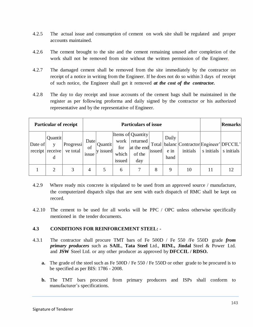
143
Signature of Tenderer
4.2.5 The actual issue and consumption of cement on work site shall be regulated and proper
accounts maintained.
4.2.6 The cement brought to the site and the cement remaining unused after completion of the
work shall not be removed from site without the written permission of the Engineer.
4.2.7 The damaged cement shall be removed from the site immediately by the contractor on
receipt of a notice in writing from the Engineer. If he does not do so within 3 days of receipt
of such notice, the Engineer shall get it removed at the cost of the contractor.
4.2.8 The day to day receipt and issue accounts of the cement bags shall be maintained in the
register as per following proforma and daily signed by the contractor or his authorized
representative and by the representative of Engineer.
Particular of receipt Particulars of issue Remarks
Date of
receipt
Quantit
y
receive
d
Progressi
ve total
Date
of
issue
Quantit
y issued
Items of
work
for
which
issued
Quantity
returned
at the end
of the
day
Total
issued
Daily
balanc
e in
hand
Contractor
initials
Engineer’
s initials
DFCCIL’
s initials
1 2 3 4 5 6 7 8 9 10 11 12
4.2.9 Where ready mix concrete is stipulated to be used from an approved source / manufacture,
the computerized dispatch slips that are sent with each dispatch of RMC shall be kept on
record.
4.2.10 The cement to be used for all works will be PPC / OPC unless otherwise specifically
mentioned in the tender documents.
4.3 CONDITIONS FOR REINFORCEMENT STEEL: -
4.3.1 The contractor shall procure TMT bars of Fe 500D / Fe 550 /Fe 550D grade from
primary producers such as SAIL, Tata Steel Ltd., RINL, Jindal Steel & Power Ltd.
and JSW Steel Ltd. or any other producer as approved by DFCCIL / RDSO.
a. The grade of the steel such as Fe 500D / Fe 550 / Fe 550D or other grade to be procured is to
be specified as per BIS: 1786 - 2008.
b. The TMT bars procured from primary producers and ISPs shall conform to
manufacturer’s specifications.
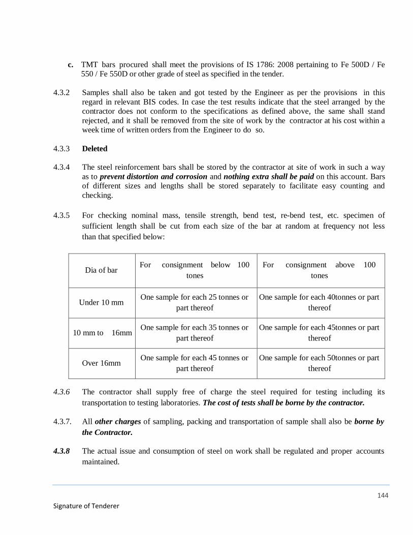
144
Signature of Tenderer
c. TMT bars procured shall meet the provisions of IS 1786: 2008 pertaining to Fe 500D / Fe
550 / Fe 550D or other grade of steel as specified in the tender.
4.3.2 Samples shall also be taken and got tested by the Engineer as per the provisions in this
regard in relevant BIS codes. In case the test results indicate that the steel arranged by the
contractor does not conform to the specifications as defined above, the same shall stand
rejected, and it shall be removed from the site of work by the contractor at his cost within a
week time of written orders from the Engineer to do so.
4.3.3 Deleted
4.3.4 The steel reinforcement bars shall be stored by the contractor at site of work in such a way
as to prevent distortion and corrosion and nothing extra shall be paid on this account. Bars
of different sizes and lengths shall be stored separately to facilitate easy counting and
checking.
4.3.5 For checking nominal mass, tensile strength, bend test, re-bend test, etc. specimen of
sufficient length shall be cut from each size of the bar at random at frequency not less
than that specified below:
Dia of bar For consignment below 100
tones
For consignment above 100
tones
Under 10 mm One sample for each 25 tonnes or
part thereof
One sample for each 40tonnes or part
thereof
10 mm to 16mm One sample for each 35 tonnes or
part thereof
One sample for each 45tonnes or part
thereof
Over 16mm One sample for each 45 tonnes or
part thereof
One sample for each 50tonnes or part
thereof
4.3.6 The contractor shall supply free of charge the steel required for testing including its
transportation to testing laboratories. The cost of tests shall be borne by the contractor.
4.3.7. All other charges of sampling, packing and transportation of sample shall also be borne by
the Contractor.
4.3.8 The actual issue and consumption of steel on work shall be regulated and proper accounts
maintained.
145
Signature of Tenderer
4.3.9 Steel brought to site and remaining unused shall not be removed from site without the
written permission of Engineer.
4.3.9 (i) Reinforcement including authorized spacer bars and lappages shall be measured in length
for different diameters as actually (not more than as specified in the drawings) used
in the work nearest to a centimetre. Wastage and unauthorized overlaps shall not be
measured.
(ii) The standard sectional weights referred to shall be as in Table 5.4 in para 5.3.4 in revised
CPWD specifications 2009 Vol. I will be considered for conversion of length of various
sizes of TMT bars in to standard weight.
(iii) Record of actual sectional weights shall also be kept dia wise and lot wise. The average
sectional weight for each diameter shall be arrived at from samples from each lot of steel
received at site. The decision of the Engineer shall be final for the procedure to be
followed for determining the average sectional weight of each lot. Quantity of each
diameter of steel received at site of work each day will constitute one single lot for the
purpose. The weight of steel by conversion of length of various sizes of bars based on the
actual weighted average sectional weight shall be termed as Derived Actual Weight.
a. If the derived weight as in sub-para (iii) above is less than the standard weight as in
sub-para (ii) above, then the Derived Actual Weight shall be taken for payment.
b. If the derived actual weight is found more than the standard weight, than standard
weight as worked out in sub para (ii) above shall be taken for payment. Nothing shall
be paid extra for the difference in Derived/ Actual Weight and standard weight.
4.3.10 Every care should be taken to avoid mixing different types of grades of bars in the same
structural members as main reinforcement to satisfy relevant clause of IS: 456. In case of
buildings, wherever the situation necessitates, the changeover shall be permitted only from
any one level onwards. In case of foundations, all foundation elements (footings and grade
beams) shall have the same kind of steel. In the case of columns, all structural elements up to
the level of change, where the changeover is taking place should have the same kind of steel
as those in columns.
4.3.11 The reinforcing steel brought to site of work shall be stored on brick / timber platform
of 30/40-cm height, nothing extra shall be paid on this account.
146
Signature of Tenderer
PART-I
CHAPTER-V
SECTION-5
METHODOLOGIES FOR GREEN BUILDINGS
5.1 To secure at least 5-Star GRIHA ratings, a high degree of responsibility and cooperation
is necessary from the contractor employed.
5.2 The following guideline provides the general concept of green, green building rating and the
expectations from each one of those involved in this project:
5.3 GENERAL NOTE ON GREEN BUILDING PRACTICES
All materials and systems used in the project are intended to maximize energy efficiency for
operation of Project throughout service life (substantial completion to ultimate disposition –
reuse, recycling, or demolition) with an emphasis on top quality. Materials and systems are
to maximize environmentally-benign construction techniques, including construction waste
recycle, reusable delivery packaging, and reusability of selected materials. All vendors /
contractors must adhere to best practices related to Green Buildings. Other than the
particular specifications / methodologies for green buildings outlined here, all vendors /
contractors will be furnished with a supplementary set of guidelines more specific to their
nature of service/product.
5.4 GREEN BUILDING PRACTICES:
5.4.1 Ensure healthy indoor air quality in final Project.
5.4.2 Maximize use of products with low embodied energy (harvesting, mining, manufacturing,
transport, installation, use, operations, recycling and disposal). Exceptions might include
materials that result in net energy conservation during their useful life in building and
building’s life cycle.
5.4.3 Where possible, select materials harvested and manufactured regionally, within a 800-km
radius of the project site.
5.4.4 Maximize use of durable products.
5.4.5 Maximize use of products easy to maintain, repair, and that can be cleaned using non-toxic
substances.
147
Signature of Tenderer
5.4.6 Maximize recycled content in materials, products, and systems.
5.4.7 Maximize use of reusable and recyclable packaging.
5.4.8 Where possible and feasible, provide for non-destructive removal and re-use of materials
after their service life in this building.
5.4.9 Re-use existing building materials to extent feasible within design concept expressed in
Contract Documents. Provide materials that utilize recycled content to maximum degree
possible without being detrimental to product performance or indoor air quality.
5.4.10 Use construction practices such as material waste reduction and dimensional planning that
maximize efficient use of resources and materials.
5.4.11 Provide or contribute to O&M Manuals wherever applicable.
5.4.12 Be conversant with the Site Waste Management Program Manual and actively contribute to
its compilation. Assist the Engineer by estimating the nature and volume of waste generated
by the process/installation in question.
5.4.13 Minimize pollution: Select materials that generate least amount of pollution during
mining, manufacturing, transport, installation, use, and disposal.
5.4.14 Avoid materials that emit greenhouse gases
5.4.15 Avoid materials that require energy intensive extraction, manufacturing, processing,
transport, installation, maintenance, or removal.
5.4.16 Avoid materials that contain ozone-depleting chemicals (e.g. CFCs or HCFCs).
5.4.17 Avoid materials that emit potentially harmful volatile organic chemicals (VOCs).
5.4.18 Employ construction practices that minimize dust production and combustible by- products.
5.4.19 Avoid materials that can leach harmful chemicals into ground water; do not allow
potentially harmful chemicals to enter sewers or storm drains.
5.4.20 Protect soil against erosion by wind or storm-water and topsoil depletion.
5.4.21 Minimize noise generation during construction; screen mechanical equipment to block
noise.
5.4.22 Select materials that can be reused or recycled and materials with significant percentage
of recycled content; conform with or exceed specified Project recycled content percentages
for individual materials; avoid materials difficult to recycle. Protect natural habitats; restore
natural habitats where feasible within scope of Project.
148
PART-I
CHAPTER-V
SECTION-6
MINIMUM QUALITY ASSURANCE PLAN (CIVIL WORK)
(MQAP)
6.1 OUTSIDE / INDEPENDENT TESTING
The Contractor shall engage outside / independent laboratories of any Government
Institutes, Indian Institutes of Technology, National Institutes of Technology, Central
and State Research Centres, Centrally and State funded laboratories or NABL accredited
laboratories (approved by Engineer/Employer) for testing of materials in accordance with
relevant CPWD Specifications / IS Codes / IRC Codes / Manufacturer’s Specifications,
etc., if testing facility is not available in the field laboratory. Where testing facilities
are not available even in aforesaid laboratories, the name of the proposed lab shall be got
approved by the Engineer.
6.2 QUALITY CONTROL TESTS
6.2.1 Field / lab tests shall be carried out to check, control and finally assure the quality of work
at every level. Material and finished item shall be subjected to test to achieve the
desired quality of work. Where ever necessary required number of test shall be
carried out in outside laboratory approved by the Engineer. The mandatory test shall be
carried out as per the provision of CPWD Specifications 2009 Volume-I & II and
relevant IS codes or any other applicable codes.
6.2.2 The lot size, number of required tests and frequency of testing shall be as per
CPWD Specifications. The number of tests indicated is minimum required test to be
performed. However, actual numbers of test may be more depending upon the actual
quantities executed and measured at site. Nothing extra shall be admissible on this
account. Decision of the Engineer shall be final and binding in this respect.
6.2.3 The independent test equal to 10% tests or as desired by Engineer/Employer of the
total number of tests performed in field laboratory shall be carried out in out-side
laboratories mentioned in para 10.2 above.
6.2.4 Any other test in the opinion of the Engineer required for establishing quality of
material or execution of work shall also got carried out by the contractor. Decision
of Engineer shall be final and binding in this respect.
149
6.2.5 The contractor shall supply free of charge the materials required for testing including
its transportation cost to testing laboratories. The cost of tests carried out shall be borne
by the contractor.
6.2.6 The contractor shall ensure quality construction in a planned and time bound manner.
Any sub-standard material / work beyond set out tolerance limit shall be summarily
rejected by the Engineer & contractor shall be bound to replace / remove such sub-
standard / defective work immediately. If any material, even though approved by Engineer
is found defective or not conforming to specifications shall be replaced / removed by
the contractor at his own risk & cost.
6.2.7 The Contractor shall submit Manufacturer Test Certificate & carry out all required testing
of material as per specifications & directions of Engineer in Charge. Testing of material
shall be carried out at a laboratory approved by Engineer in Charge & testing charges
shall be borne by the contractor.
Engineer in charge may also test portion of the finished works already done in order to
prove soundness and efficiency of the material/work. The test results thus obtained shall
be final and binding to the contractor. Cost of transportation of material for testing &
testing charges shall be borne by Contractor.
If after any such tests, the material/work/portion of the works are found defective or
unsound, the contractor shall remove/dismantle the rejected material/work and reconstruct
the same at his own cost as per the directions of Engineer whose decision would be
binding.
6.3 SHUTTERING SCHEDULE, MACHINERY AND OTHER TOOL & PLANTS
6.3.1 Minimum requirement of shuttering shall be drawn as per construction program. A
proper shuttering schedule showing quantity of shuttering to be brought at site either in
one lot or at different stages of work shall be submitted prior to start of work for
the approval of Engineer.
Entire machinery and T&P may not be required at the start of work, therefore, a
proper time schedule by which each machinery and T&P is to be brought at site shall be
submitted prior to start of work for the approval of Engineer.
6.4 REMOVAL OF REJECTED/SUB-STANDARD MATERIALS
The following procedure shall be followed for the removal of rejected/sub-standard
materials from the site of work:
a Whenever any material brought by the contractor to the site of work is rejected, entry
thereof should invariably be made in the Site Order Book under the signature of the
150
Engineer, giving the approximate quantity of such materials.
b As soon as the material is removed, a certificate to that effect shall be recorded by the
Engineer against the original entry, giving the date of removal and mode of removal,
i.e., whether by truck, carts, or by manual labour. If the removal is by truck, the
registration number of the truck should be recorded.
c When it is not possible for the Engineer to be present at the site of work at the time of
actual removal of the rejected/sub-standard materials from the site, the required
certificate should be recorded by the person appointed by Engineer, and the Engineer
should countersign the certificate recorded by the person so appointed.
6.5 Custody & Reporting of Records
6.5.1 All the records shall be maintained jointly by laboratory in-charge and the authorized
representative of Engineer. Records shall be maintained in the shape of registers and shall
be kept in the safe custody of Engineer of work. Status of mandatory test shall be
reported at the time of presentation of each running account bill or monthly progress
reports.
6.6 Maintenance of register of test:
i. All samples of materials including cement concrete cubes shall be taken jointly with
contractor by Engineer’s representative. All the necessary assistance shall be provided
by the contractor. Cost of sample materials is to be borne by the contractor and he shall
be responsible for safe custody of samples to be tested at site.
ii. All the tests in field lab setup at construction site shall be carried out by the engineering
staff deployed by the contractor in presence of Engineer’s representative where possible.
iii. All the entries in the register will be made by the designated engineering staff of the
contractor and same should be regularly reviewed by Engineer.
6.7 Maintenance of Site Records & Quality Records:
a. The Contractor shall maintain records, plans and charts (CGM/PERT) showing the date and
progress of all main operation and activities. The Engineer shall have access to the
information at all times. All tests will be conducted in presence of Engineer’s representative.
Records of those shall be handed over to the Engineer’s representative/officer carrying out
tests.
b. In addition to Quality Record the following registers shall be maintained at site by the
Engineer and the Contractor shall furnish all the required details from time to time.
151
c. The Contractor shall promptly sign the order given therein by the Engineer or his
representative or his superior officers and comply with them. The compliance shall be
reported by the contractor to the Engineer in reasonable time to enable Engineer/his
representative to check the same.
d. The register will be maintained to show the daily strength of labour in different categories
employed by the contractor. The same shall be signed daily by representatives of contractor
and Engineer for their correctness.
e. The particulars of machineries with contractor in working condition and working at site to
be recorded jointly on each day.
f. All events are required to be chronologically logged in the register.
g. All test results of materials used in works shall be maintained.
h. All the drawings fit for construction issued to contractor, date wise will be maintained with
latest revision.
i. The register of Engineer & other staff at work site shall be maintained on daily basis.
j. Other Register for cement, Steel or any other important items as directed by Engineer shall
be maintained at site by Contractor.
6.8 Records to be produced by the Contractor for inspection
a. The contractor shall whenever required by the Engineer or his authorized representatives
produce or cause to be produced for examination any quotation, invoice cost or any copy of
or extract from any accounts, books, vouchers, receipts, letter, memorandum or any copy of
or extract from any such documents and also furnish information as may be required
relating to the execution of this contract or relevant for verifying or ascertaining the
materials supplied by the Contractor are in accordance with the specifications laid down in
the contract etc. The Engineer decision on the question or relevancy of any document or
information or returns will be final and binding on the contractor.
b. The work may be inspected by the Engineer/Statutory Authority etc. and Vigilance and
Technical Department of CVC etc. and the contractor is bound by their decisions in respect
of quality, quantity and amount payable/recoverable under this contract.

152
Signature of Tenderer
PART – II
TECHNICAL SPECIFICATIONS
153
Signature of Tenderer
PART-II
CHAPTER-1
TECHNICAL SPECIFICATIONS FOR SUB STATION WORKS
154
Signature of Tenderer
1 TECHNICAL SPECIFICATIONS
1.1 GENERAL
Electrification works shall be carried out in conformity with Indian Electricity Act 1910
as amended and Indian Electricity Rules 1956 as amended up to date. Wherever
applicable, relevant Indian Standard Code of Practice for external electrical installation
(latest amendments/revisions) supplementary regulations or byelaws of Licenses and
Electricity Undertaking Board shall be adopted.
1.2 STANDARDS
All equipment, material and components shall comply with the requirements of the
latest editions of Indian Standards with updated amendments. Standards and
Regulations applicable in the area where equipment is to be installed shall also be
followed.
The equipment offered complying with other standards, these standards shall be equal to
or superior to those specified and full details of the differences shall be furnished along
with the tender.
IS 13947 : A.C. Circuit Breakers (Relevant Parts/SCC).
IS 3427 : Metal enclosed Switchgear & Control Gear.
BS 162 : Safety Clearances.
IS 2705 : Current Transformers (Parts 1 to 4).
IS 3156 : Voltage Transformers (Parts 1 to 4).
IS 3202 : Code of Practice for climate proofing of electrical equipment.
IS 375 : Marking & Arrangement for Switchgear Bus Bars, main
connections and auxiliary wiring.
IS 722 : A.C. Electric Meters.
IS 1248 : Direct acting Electrical Indicating Instruments.
IS 3231 : Electrical Relays for Power System Protection.
IS 2544 : Epoxy Cast Resin Insulators.
IS 5082 : Electrolytic Copper and Aluminum.
IS 5792 : High Voltage HRC fuses.
155
Signature of Tenderer
2 33 kV SWITCHGEARS
2.1 GENERAL
The technical specifications cover the equipment to be supplied for a 33 kV
Switchboards suitable for 33 kV 3 phase earthed system. 50 HZ AC supply with a fault
level of 1500 MVA at 33kV. The equipment shall be suitable for continuous operation
at the stipulated ambient conditions.
2.2 STANDARDS AND CODES
The following Indian Standards Specifications and Codes of Practice shall apply to the
equipment covered by this Contract. In addition, the relevant clauses of the Indian
Electricity Act 1910 and Indian Electricity Rules 1956 as amended up to date shall also
apply. Wherever appropriate Indian Standards are not available, relevant British and/or
IEC Standards shall be applicable.
BIS certified equipment shall be used as a part of the Contract in line with Government
Regulations. Necessary Test Certificates in support of the certification shall be
submitted prior to supply of the equipment.
It is to be noted that updated and current Standards shall be applicable irrespective of
those listed below.
33000 volt Circuit Breaker IS 13118; 1991
Metal Enclosed Switchgear and Control gear for voltages above 1000 volts IS
3427 : 1969
Electrical Relays for Power System Protection IS 3231 : 1986
Voltage Transformers IS 3156 : 1978
Current Transformers IS 2705 : 1981
Rubber Mats for Electrical Works IS 5424 : 1983
Danger Notice Plate IS 2551 : 1982
2.3 33 kV VACUUM CIRCUIT BREAKERS
2.3.1 Technical Parameters
The 33000 volt circuit breakers shall be triple pole Vacuum type suitable for indoor
mounting and shall comply with the requirements of the relevant Indian Standards. The
Circuit Breakers shall be suitable for operation at 11000 volts 3 phase 50 Hz supply

156
Signature of Tenderer
system and shall have a certified symmetrical breaking capacity of 1500 MVA at 33000
volts or as stipulated in schedule of quantities.
2.3.2 Technical Specifications
The Circuit Breakers shall be Vacuum type and shall consist of three identical single
pole vacuum interrupter units which shall comprise of a pair of butt contacts enclosed
within a sealed ceramic body with SS end plates. The moving contacts shall be sealed
into the enclosure via a SS steel bellow which shall permit axial movement of the
contact. The contact arrangement shall be surrounded by SS sputter shield to prevent
condensation of metal on the inside of the insulating envelop and also to provide good
voltage grading across the gap and the outer envelope. The contact material and the
contact geometry shall be suitable for the purpose so as to attain current chopping at
minimum current to prevent build-up of unduly high over voltages and to prevent the
arc to cause localised high spots on the contact.
The Circuits Breaker shall be suitable for switching duty of Transformers
2.3.3 CIRCUIT BREAKER CONSTRUCTIONAL FEATURES
The 33000 volt circuit breaker shall be flush front, metal clad, truck mounted , drawout
type and fully interlocked. The truck that carries the Circuit Breaker shall be of rigid
fabricated construction. Each Circuit Breaker shall be housed in a separate compartment
enclosed on all sides.
Each withdrawable truck shall have its own Circuit Breaker.
All electrical connections on the truck shall be brought to secondary plugs which engage
similar sockets in the housing.
The Circuit Breakers shall be of the double break type. Interphase barriers and tank
lining of insulating material shall be provided.
The drawout mechanism shall be so designed and constructed as to permit smooth
withdrawal and insertion. The movement shall be free of jerks, easy to operate and
positive.
All current carrying parts in the Circuit Breaker shall be silver plated and suitable arcing
contacts shall be provided to protect the main contacts.
Isolating contacts of the spring loaded self aligning pattern shall be provided for the
Circuit Breaker. Suitable arc control devices shall be mounted around the fixed contacts.
Terminal insulators of synthetic resin bonded paper shall be provided suitable for the
specified short circuit level
Sheet steel barriers shall be provided between

157
Signature of Tenderer
Instrument Panel and Potential Transformer
Instrument Panel and Current Transformers
Busbar chamber and Circuit Breaker compartments
2.3.4 CIRCUIT BREAKER OPERATING MECHANISM
The Circuit Breaker shall be trip free and equipped with a motor power operated closing
mechanism. The operating mechanism shall be such that the Circuit Breaker is at all
times free to open immediately the trip coil is energised.
Mechanical ON/OFF position indication shall be provided on the front of the circuit
breaker.
The operating mechanism shall be mounted on the front panel of the truck.
The operating handle and the mechanical trip push button shall be at the front of and
integral with the Circuit Breaker.
The operating mechanism shall provide four distinct and separate positions of the
Circuit Breaker on the cradle
Service
Test
Isolated
Maintenance
2.3.5 CIRCUIT BREAKER INTERLOCKING
Each Circuit Breaker shall be provided with the following mechanical safety interlocks
to ensure protection to the equipment and the operator.
The Circuit Breaker cannot be closed unless it is in the 'PLUGGED IN' position.
The Circuit Breaker cannot be withdrawn from or pushed into the housing unless the
main contacts are open.
The Circuit Breaker cannot be put into service without making the secondary
connections between the truck and housing.
The cover of the drawout voltage transformer cannot be opened unless the transformer
is isolated.
158
Signature of Tenderer
2.3.6 CIRCUIT BREAKER AUXILIARY CONTACTS
The Circuit Breaker shall have a minimum of 6 N.O. and 6 N.C. auxiliary contacts rated
at 5 amps. These contacts shall close before the main contacts when the Circuit Breaker
is plugged in and vice versa when the Circuit Breaker is lowered.
2.3.7 PROTECTIVE RELAYS
The Circuit Breaker shall have overcurrent, earth fault protection and auxiliary relay
devices as specified in the Schedule of Quantities. These relays shall be mounted flush
on a separate compartment with access from the rear for wiring and maintenance.
2.4 POTENTIAL AND INSTRUMENT TRANSFORMERS
A drawout type cast resin voltage transformer shall be mounted in the panel and
connected to the line. The tank shall be arranged for horizontal isolation.
The Circuit Breaker shall have the required current transformers as specified in the
Schedule of Quantities for metering and protection mounted outside the Circuit Breaker
compartment but within the free standing cubicle. The transformers shall comply to the
relevant Indian Standards. All curent transformers for metering shall be Accuracy Class
I and of capacity and ratio as required. Separate sets of current transformers shall be
providede for metering and protection.
2.5 INSTRUMENTATION
Instruments and indicating lamps as required in the Schedule of Quantities shall not be
mounted on the Circuit Breaker compartment door. A separate adequate compartment
shall be provided. The instruments and relays shall be accessible for teaaa sting
and maintenance without danger of accidental contact with live parts in the Switchgear
Panel.
Square pattern flush mounting meters and selector switches of the three way and OFF
pattern complying with the requirements of the relevant Indian Standards shall be used.
The current transformers for metering and protection shall be mounted on the solid
copper busbars with proper supports.
LED type indicating lamps shall be provided for phase and other operational
indications.
2.6 TYPE TEST CERTIFICATES
The Contractor shall submit type test certificates of the Circuit Breakers complying with
the relevant Indian Standards from a recognized Test House.
159
Signature of Tenderer
33 KV SWITCHGEAR PANEL
3.1 General
The switchgear panels shall be suitable for operation at 33000 volt 3 phase 50 Hz supply
system with a short circuit withstand of 1500 MVA at 33,000 volts and a corresponding
short time rating for 1 second.
The Switchgear panels shall comply with the requirements of the latest edition with upto
date amendments of the relevant Indian Standards Specifications, Indian Electricity
Rules and Regulations.
3.2 Switchgear Configuration
The panel shall be configured with 33,000 volt Circuit Breakers, associated metering
and protective devices and other equipment as called for in the Bill of Quantities.
Each 33,000 volt Circuit Breaker shall be housed in an individual panel in single tier
formation.
3.3 Equipment Specifications
All equipment used to configure the Switchgear Panel shall comply to the relevant
Standards and Codes of the Bureau of Indian Standards and the detailed technical
specifications as included in this tender document.
3.4 Constructional Features
The 33000 volts Switchgear Panel shall be totally enclosed, metal clad, cubicle pattern,
floor mounting, extensible on both sides and suitable for indoor use.
The Switchgear Panels shall be totally enclosed and completely dust and vermin proof.
Synthetic rubber gaskets between all adjacent units and beneath all covers shall be
provided to render the joints dust and vermin proof. All doors and covers shall also be
fully gasketed with synthetic rubber and shall be lockable.
The Switchgear Panels shall be fabricated with CRCA Sheet Steel of thickness not less
than 2.0 mm and shall be folded and braced as necessary to provide a rigid support for
all components. The doors and covers shall be constructed from CRCA Sheet Steel of
thickness not less than 1.6 mm. Joints of any kind in sheet steel shall be seam welded
and all welding slag ground off and welding pits wiped smooth with plumber metal.
All panels and covers shall be properly fitted and square with the frame. The holes in
the panel shall be correctly positioned.
Fixing screws shall enter holes tapped into an adequate thickness of metal or provided
with hank nuts. Self threading screws shall not be used in the construction of the
Switchgear Panels.

160
Signature of Tenderer
3.5 Switchgear Panel Limitations
A base channel of 75 mm x 5 mm thick shall be provided at the bottom.
The Switchgear Panel height shall normally be restricted to a maximum of 2300 mm.
3.6 Switchgear Panel Compartmentalization
The Switchgear Panels shall be divided into distinct separate compartments comprising
A completely enclosed ventilated dust and vermin proof bus bar compartment for the
vertical and horizontal busbars.
Each Circuit Breaker shall be housed in a separate compartment enclosed on all sides.
Separate and adequate compartments shall be provided for accommodating instruments,
indicating lamps, protective relays, control fuses etc as required. These shall be
accessible for testing and maintenance without any danger of accidental contact with
live parts.
A horizontal wireway with screwed covers shall be provided at the top to take
interconnecting control wiring between vertical sections.
Cable compartment shall be of adequate size for easy termination of all incoming and
outgoing cables. Adequate and proper supports shall be provided in the compartment for
supporting the cables.
3.7 Switchgear Panel Busbars
The main horizontal and vertical interconnection busbars shall be of hard drawn high
conductivity electrolytic copper and of rectangular cross sections suitable for full rated
current. The current density for copper shall be 1.25 amps per sq. mm. and suitable to
withstand the electromagnetic and thermal stresses of a 1500 MVA fault level at 33,000
volts for 3 second.
The busbars and interconnections shall be insulated with fibre glass sleeves.
The busbars shall be extensible on either side of the Panels.
The busbars shall be supported on non-breakable, non-hygroscopic insulated supports at
regular intervals to withstand the stresses of a 1500 MVA fault level.
All busbars and interconnections shall be colour coded.
The main horizontal busbars shall run through the entire length of the Switchgear
Panels.
161
Signature of Tenderer
3.8 Switchgear Panel Interconnections
All interconnections shall be with solid electrolytic copper of adequate size to carry the
full rated current and fibre glass insulated.
3.9 Drawout Features
All Circuit Breakers shall be provided in fully drawout cubicles. These cubicles shall be
such that drawout is possible without disconnection of the wires and the cables. The
power and control circuits shall have self aligning and self isolating contacts which shall
be easily accessible for maintenance. Mechanical interlocks shall be provided on the
drawout cubicles to ensure safety and compliance to the relevant Standards.
3.10 Switchgear Panel Interlocks
Each group of busbars and feeder connections shall be fitted with automatically
operated safety shutters with positive opening and closing when the Circuit Breaker is
raised or lowered.
Facility shall be provided for hand operation of the shutters and latching in either open
or closed position.
Padlocking provision of the shutter in the closed position shall be included for
maintenance purposes.
3.11 Instruments And Protection Relays
Instruments, indicating lamps and all protection and control relays shall not be mounted
on the Circuit Breaker compartment door. A separate adequate compartment shall be
provided. The instruments and relays shall be accessible for testing and maintenance
without danger of accidental contact with live parts in the Switchgear Panel.
LED type indicating lamps shall be provided for phase and other operational
indications.
The current transformers for metering and protection shall be mounted on the solid
copper busbars with proper supports.
3.12 Switchgear Panel Internal Wiring
All wiring for relays and metering shall be with PVC insulated copper conductor wires.
The wiring shall be coded and labelled with approved ferrules for identification. The
minimum size of copper conductor control wires shall be 2.5 sq.mm.
All control circuits shall be provided with 10 kA MCB's Instrument testing plugs shall
be provided for testing the meters.
162
Signature of Tenderer
3.13 Cable Terminations
Knock out holes of appropriate size and number shall be provided in the Panels in
conformity with the location of the incoming and outgoing cables.
The cable terminations of the Circuit Breakers shall be brought out to terminal cable
sockets suitably located in the cable chamber at the rear of the panels.
3.14 Space Heaters
The Switchgear Panel shall have in each panel thermostatically controlled space heaters
with a controlling 16 amp 230 volt socket outlet with MCB to eliminate condensation.
3.15 Earthing
Two main earth bars of copper as required shall be provided throughout the length of
the Switchgear Panels with a provision to make connections on both sides to the sub-
station earths.
3.16 Designation Labels
Suitably engraved white on black name plates and identification labels of metal for all
Panels and circuits shall be provided. These shall indicate the feeder number and the
designation
3.17 Sheet Steel Treatment And Painting
Sheet steel materials used in the construction of the Switchgear Panels should have
undergone a rigorous rust proofing process comprising of alkaline degreasing, descaling
in dilute sulphuric acid and a recognised phosphating process. The sheet steel work shall
then receive two coats of oxide filler primer before final painting. Castings shall be
scrupulously cleaned and fettled before receiving a similar oxide primer coat.
All sheet steel work shall after metal treatment be spray or powder painted with two
coats of shade 692 to IS 5 on the outside and white on the inside. Each coat of paint
shall be properly stoved and the paint thickness shall be not less than 50 microns.
The circuit breakers shall be provided with following accessories:
Auxiliary switch with 5NO + 5NC contacts.
Mechanical operation counter
Spring charging handle
Recharging in/out handle
Foundation bolts
163
Signature of Tenderer
Maintenance manual
Instruction manual
3.18 Auxiliary supply
The tipping shall be at 24 V DC through a battery bank unit.
Space heater, Indication and other auxiliary supply shall be through to 230 V AC
3.19 Site Test
Alignment panel, interconnection of bus bar and tightness of bolts and connection
Inter panel wiring
Free movement of circuit breaker trolley
Manual/electrical operation of the breaker
Megger test
CT/PT ratio/Polarity primary injection test.
Secondary injection test on relays
4.0 33 KV AND MEDIUM VOLTAGE CABLES
4.1 GENERAL
Technical specifications in this section covers supplying and laying of :
33 kV cables
Medium voltage cables.
4.2 STANDARDS AND CODES
All equipments, components, materials and entire work shall be carried out in
conformity with applicable and relevant Bureau of Indian Standards and Codes of
Practice, as amended upto date and as below. In addition, relevant clauses of the Indian
Electricity Act 1910 and Indian Electricity Rules 1956 as amended upto date shall also
apply. Wherever appropriate Indian Standards are not available, relevant British and /or
IEC Standards shall be applicable.
Equipments certified by Bureau of Indian Standards shall be used in this contract in line
with government regulations. Test certificates in support of this certification shall be
submitted, as required.
It is to be noted that updated and current standards shall be applicable irrespective of
dates mentioned along with ISS's in the tender documents.
PVC insulated heavy duty cables IS 1554 - 1988
Cross link polyethylene insulated PVC (sheathed XLPE cables) IS 7098 - 1985

164
Signature of Tenderer
Code of practice for installation and maintenance of power cables IS 1255 - 1983
Conductors for insulated electrical cables IS 8130 - 1984
Drums for electrical cable IS10418- 1982
Methods of test for cables IS10810- 1988
Recommended current rating IS 3961 - 1987
Recommended short circuit rating of high voltage PVC cables IS 5891 - 1970
4.3 CABLES
4.3.1 33 kV Cables
33 kV cable shall be aluminium conductor with cross linked polyethylene (XLPE)
insulation, galvanized steel armouring and PVC sheathing conforming to IS 7098.
Conductors shall be sector shaped, made from electrical purely aluminium of 3 x 4 H or
H temper conforming to IS 8130 XLPE insulation of high purity shall be extruded on
the conductors with screen a layer of semi-conducting material shall be applied over the
XLPE insulation to prevent partial discharge at insulation surface. This shall be
followed up by metallic aluminium tape screen the cores shall be discharged tested.
Built up cores shall then be laid up and filler codes added. Combined core shall be
provided with extruded PVC sheathing. Galvanized steel wire of strip armouring shall
then be provided protected by an overall extruded black PVC sheet. The outer sheath
shall bear the manufacturer's name and trade mark at every meter length.
4.3.2 Medium Voltage Cables
Medium voltage cables shall be aluminium conductor XLPE insulated, PVC sheathed
armoured conforming to IS 7098. Cables shall be rated for a 1100 Volts. The conductor
of cables from 16 Sq. mm. to 50 Sq. mm. shall be stranded. Circular shaped stranded
conductors shall be used for cables of 50 sq. mm and above. Conductors shall be made
of electrical purity aluminium 3/4 H or H temper. Conductors shall be insulated with
high quality XLPE base compound. A common covering (bedding) shall be applied over
the laid up cores by extruded sheath of unvulcanised compound. Armouring shall be
applied over outer sheath of PVC sheathing. The outer sheath shall bear the
manufacturer's name and trade mark at every meter length. Cores shall be provided with
following colour scheme of XLPE insulation.
1 Core : Red/Black/Yellow/Blue
2 Core : Red and Black
3 Core : Red, Yellow and Blue
3 1/2 /4 Core : Red, Yellow, Blue and Black

165
Signature of Tenderer
Current ratings shall be based on the following conditions.
a) Maximum conductor temperature 900 C
b) Ambient air temperature 450 C
c) Ground temperature 300 C
d) Depth of laying 1000 mm
Short circuit rating of cables shall be as specified in IS 7098 Part-I.
Cables have been selected considering conditions of maximum connected loads, ambient
temperature, grouping of cables and allowable voltage drop. However, the contractor
shall recheck the sizes before cables are fixed and connected to service.
4.4 DELIVERY, STORAGE AND HANDLING
Cable drum shall be stored on a well drained, hard surface, preferably of concrete, so
that the drums do not sink in ground causing rot and damage to the cable drum. The
cable drum shall conform to IS 10418. During storage, periodical rolling of drums, in
the direction of arrow marked on the drum, shall be done once in 3 month through 900
C
Both ends of cables shall be properly sealed to prevent moisture ingress Drums shall be
stored in well ventilated area protected from sun and rain. Drums shall always be rested
on the flanges and not on flat sides. Damaged battens of drums etc. shall be replaced.
Movement of drums shall always be in direction of the arrow marked on the drum. For
transportation over long distance, the drums shall either be mounted on drum wheels
and pulled by ropes or they shall be mounted on trailers etc. drums shall be unloaded
preferably by crane otherwise they shall be rolled down carefully on suitable ramps.
While transferring cable form 1 drum to another, the barrel of the new drum shall have
diameter not less than the original drum. Cables with kinks or similar visible defects like
defective armouring etc shall be rejected. Cables shall be supplied at site in cut pieces as
per actual requirements.
4.5 LAYING OF CABLES
Cables shall be so laid that the maximum bending radius is 12 times the overall diameter
of the cable for medium voltage cables and 20 times the overall diameter for 33 kV
cables. Cables shall be laid in masonry trenches, directly on walls/cable trays, directly
buried in ground or in pipes/ducts as elaborated below. Cables of different voltages and
also power and control cables shall be laid in different trenches with adequate
separation. Wherever available space is restricted such that this requirement cannot be
met, medium voltage cables shall be laid above HT cables.
166
Signature of Tenderer
4.6 In Masonry Trenches
Wherever so specified, cables shall be laid in indoor/outdoor masonry/RCC trenches to
be provided by Owners. Cables shall be laid on MS supports fabricated from minimum
38mm x 38mm x 6mm painted / galvanized angle iron supports grouted in trench walls
at intervals not exceeding 600 mm. If required, cables shall be arranged in tier formation
inside the trench. Suitable clamps, hooks and saddles shall be used for securing the
cables in position and dressing properly so that the clear spacing between the cables
shall not be less then the diameter of the cable. Trenches shall be provided with
chequered plate/RCC covers. Wherever so specified, trenches shall be filled with fine
sand.
4.7 On Trays/Walls
Wherever so specified, cables shall be laid along walls/ceiling or on cable trays. Cable
shall be secured in position and dressed properly by means of suitable clamps, hooks,
saddles etc. such that the minimum clear spacing between cables is diameter of the
cable. Clamping of cables shall be at minimum intervals as below.
Note :The fixing intervals specified apply to straight runs. In the case of bends,
additional clamping shall be provided at 30 cm from the center of the bend on both
sides.
Cable trays, of sizes as per schedule of quantities and drawings shall be of perforated
doubled bend channel/ladder design unless otherwise stated. Cable trays shall be
fabricated from minimum 2 mm thick sheet steel and shall be complete with tees,
elbows, risers, and all necessary hardware. Cable trays shall comply with the following:
Trays shall have suitable strength and rigidity to provide proper support for all
contained cables. Trays shall not have sharp edges, burrs or projections injurious to
cable insulation. Trays shall include fittings for changes in direction and elevation.
Cable trays and accessories shall be painted with one shop coated of red oxide zinc
chromate primer and two side coats of aluminium alkyd paint or approved equivalent.
Cable trays shall not have sharp edges, burrs or projection that may damage the
Type of
cables
Size Clamping by Fixing
intervals
MV Upto and including 25
sq mm
Saddles 1 mm thick 45 cm
MV &
HV
35 sq mm to 120 sq mm Clamps 3 mm thick 25
mm wide
60 cm
MV &
HV
150 sq mm and above Clamps 3 mm thick 40
mm wide
60 cm
167
Signature of Tenderer
insulation jackets of the wiring. Cable trays shall have side rails or equivalent structural
members.
Unless otherwise specifically noted on the relevant layout drawing, all cable tray
mounting works to be carried out ensuring the following :
Cable tray mounting arrangement type to be as marked on layout drawing. Assembly of
tray mounting structure shall be supplied fabricated, erected & painted by the electrical
contractor. Tray mounting structures shall be welded to plate inserts or to structural
beams as approved by the Clients. Wherever embedded plates & structural beams are
not available for welding the tray mounting structure electrical contractor to supply the
MS plates & fix them to floor slab by four anchor fasteners of minimum 16 mm dia
having minimum holding power of 5000 Kg at no extra cost. Maximum loading on a
horizontal support arm to be 120 Kg. metre of cable run. Width of the horizontal arms
of the tray supporting structures to be same as the tray widths specified in tray layout
drawings, plus length required, for welding to the vertical supports. The length of
vertical supporting members for horizontal tray runs shall be to suit the number of tray
tiers shown in tray layout drawings. Spacing between horizontal supports arms of
vertical tray runs to be 300 mm. Cable trays will be welded to their mounting supports.
Minimum clearance between the top most tray tier and structural member to be 300 mm.
Cables in vertical race ways to be clamped by saddle type clamps to the horizontal
slotted angels. Clamps to be fabricated from 3 mm thick aluminium strip at site by the
electrical contractor to suit cable groups. The structural steel (standard quality) shall be
according to latest revision of IS : 226 & 808. Welding shall be as per latest revisions of
IS : 816. All structural steel to be painted with one shop coat of red oxide and oil primer
followed by a finishing coat of aluminium alkyd paint where any cuts or holes are made
on finished steel work these shall be sealed against oxidation by red oxide followed by
the same finishing paint. Steel sheet covers wherever indicated to be similarly painted.
Trays shall be erected properly to present a neat and clean appearance. Trays shall be
installed as a complete system. Trays shall be supported adequately by means of painted
MS structural members secured to the structure by dash fasteners or by grouting. The
entire cable tray system shall be rigid. Each run of cable tray shall be completed before
laying of cables. Cable trays shall be erected so as to be exposed and accessible.
4.8 Buried Directly In Ground
4.8.1 General
Cables shall be so laid that they will not interfere with under ground structures. All
water pipes, sewage lines or other structures which become exposed by excavation shall
be properly supported and protected from injury until the filling has been rammed
solidly in places under and around them. Any telephone or other cables coming in the
way are to be properly shielded as directed by Clients/Owners. Surface of the ground
168
Signature of Tenderer
shall be made good so as to conform in all respects to the surrounding ground to the
satisfaction of Clients/ Owners.
4.8.2 Routing of cables
Before cable laying work is undertaken, the route of the cables shall be decided with the
Clients/Owners. While shortest practicable route shall be preferred, cable runs shall follow
fixed development such as roads, footpaths etc with proper off-sets so that future
maintenance and identification are rendered easy. Whenever cables are laid along well
demarcated or established roads, the LV/MV cables shall be laid further from the kerb line
than HV cables. Cables of different voltages and also power and control cables shall be
kept in different trenches with adequate separation. Where available space is restricted,
LV/MV cables shall be laid above HV cables. Where cables cross one another, the cables
of higher voltage shall be laid at a lower level than the cables of lower voltage. Power and
communication cables shall as far as possible cross at right angles. Where power cables
are laid in proximity to communications cables the horizontal and vertical clearances shall
not normally be less than 60 cm.
4.8.3 Width of Trench
The width of trench shall be determined on the following basis. The minimum width of
trench for laying single cables shall be 350 mm. Where more than one cable is to be laid in
the same trench in horizontal formation, the width of trench shall be increased such that
the inter-axial spacing between the cables except where otherwise specified shall be at
least 200 mm. There shall be a clearance of at least 150 mm between axis of the end cables
and the sides of the trench.
4.8.4 Depth Of Trench
The depth of trench shall be determined on the following basis:
Where cables are laid in single tier formation, the total depth of the trench shall not be
less than 750 mm for cables upto 1.1 kV and 1250 mm for cables above 1.1 kV.
When more than one tier of cables is unavoidable and vertical formation of laying is
adopted, the depth of trench shall be increased by 300 mm for each additional tier to be
formed.
4.8.5 Excavation of Trenches
The trenches shall be excavated in reasonably straight lines. Wherever there is a change in
direction, suitable curvature of 12 times the overall diameter of the largest cable shall be
provided. Where gradients and changes in depths are unavoidable these shall be gradual.
Excavation should be done by any suitable manual or mechanical means. Excavated soil
shall be stacked firmly by the side of the trench such that it may not fall back into the
trench. Adequate precautions shall be taken not to damage any existing cables, pipes or
other such installations during excavation. Wherever bricks, tiles or protected covers or
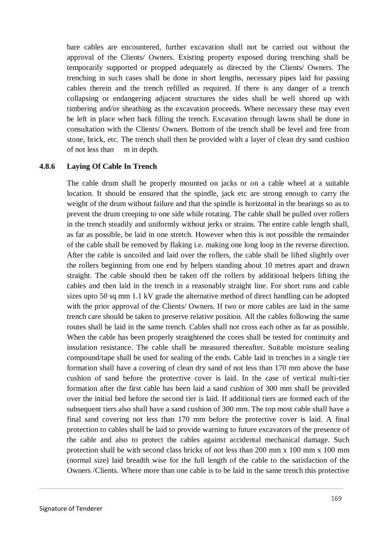
169
Signature of Tenderer
bare cables are encountered, further excavation shall not be carried out without the
approval of the Clients/ Owners. Existing property exposed during trenching shall be
temporarily supported or propped adequately as directed by the Clients/ Owners. The
trenching in such cases shall be done in short lengths, necessary pipes laid for passing
cables therein and the trench refilled as required. If there is any danger of a trench
collapsing or endangering adjacent structures the sides shall be well shored up with
timbering and/or sheathing as the excavation proceeds. Where necessary these may even
be left in place when back filling the trench. Excavation through lawns shall be done in
consultation with the Clients/ Owners. Bottom of the trench shall be level and free from
stone, brick, etc. The trench shall then be provided with a layer of clean dry sand cushion
of not less than m in depth.
4.8.6 Laying Of Cable In Trench
The cable drum shall be properly mounted on jacks or on a cable wheel at a suitable
location. It should be ensured that the spindle, jack etc are strong enough to carry the
weight of the drum without failure and that the spindle is horizontal in the bearings so as to
prevent the drum creeping to one side while rotating. The cable shall be pulled over rollers
in the trench steadily and uniformly without jerks or strains. The entire cable length shall,
as far as possible, be laid in one stretch. However when this is not possible the remainder
of the cable shall be removed by flaking i.e. making one long loop in the reverse direction.
After the cable is uncoiled and laid over the rollers, the cable shall be lifted slightly over
the rollers beginning from one end by helpers standing about 10 metres apart and drawn
straight. The cable should then be taken off the rollers by additional helpers lifting the
cables and then laid in the trench in a reasonably straight line. For short runs and cable
sizes upto 50 sq mm 1.1 kV grade the alternative method of direct handling can be adopted
with the prior approval of the Clients/ Owners. If two or more cables are laid in the same
trench care should be taken to preserve relative position. All the cables following the same
routes shall be laid in the same trench. Cables shall not cross each other as far as possible.
When the cable has been properly straightened the cores shall be tested for continuity and
insulation resistance. The cable shall be measured thereafter. Suitable moisture sealing
compound/tape shall be used for sealing of the ends. Cable laid in trenches in a single t ier
formation shall have a covering of clean dry sand of not less than 170 mm above the base
cushion of sand before the protective cover is laid. In the case of vertical multi-tier
formation after the first cable has been laid a sand cushion of 300 mm shall be provided
over the initial bed before the second tier is laid. If additional tiers are formed each of the
subsequent tiers also shall have a sand cushion of 300 mm. The top most cable shall have a
final sand covering not less than 170 mm before the protective cover is laid. A final
protection to cables shall be laid to provide warning to future excavators of the presence of
the cable and also to protect the cables against accidental mechanical damage. Such
protection shall be with second class bricks of not less than 200 mm x 100 mm x 100 mm
(normal size) laid breadth wise for the full length of the cable to the satisfaction of the
Owners /Clients. Where more than one cable is to be laid in the same trench this protective
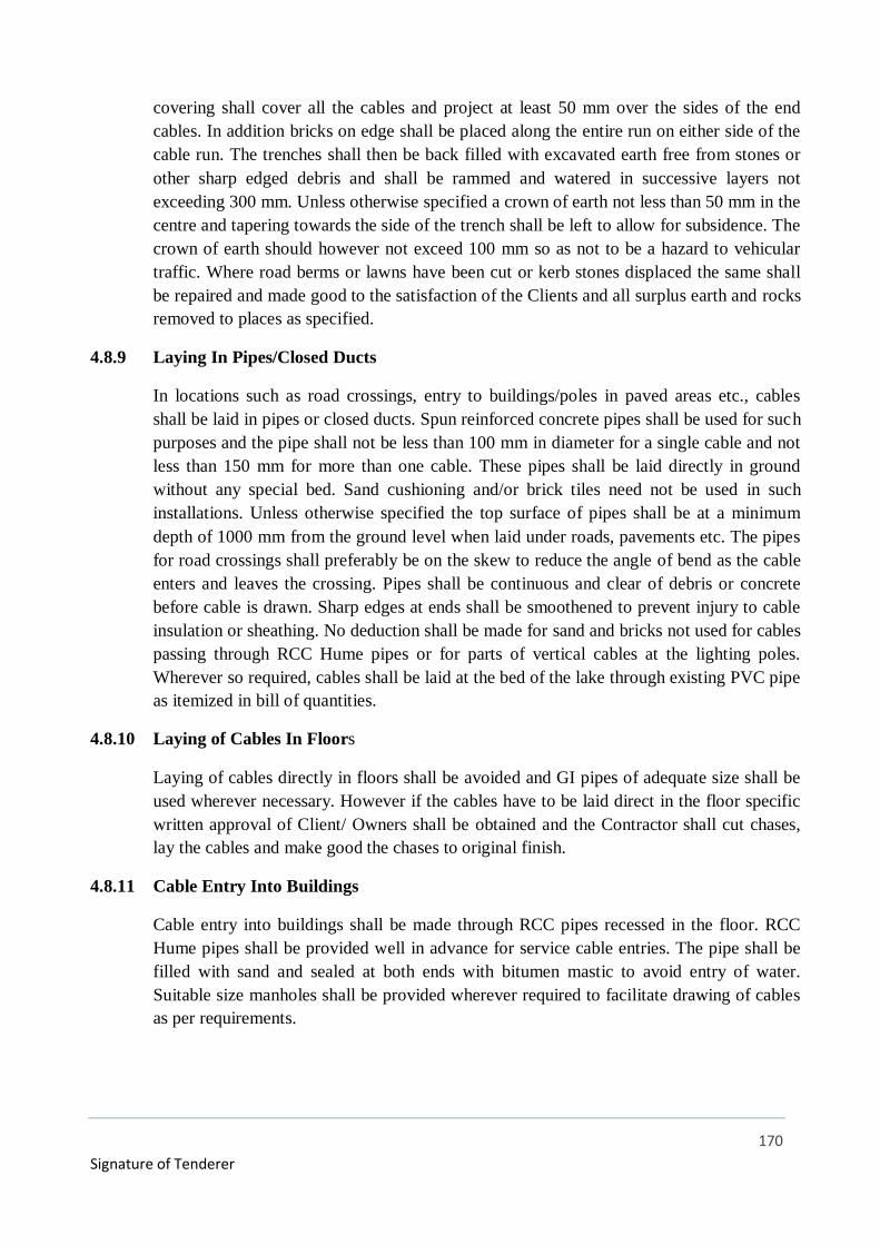
170
Signature of Tenderer
covering shall cover all the cables and project at least 50 mm over the sides of the end
cables. In addition bricks on edge shall be placed along the entire run on either side of the
cable run. The trenches shall then be back filled with excavated earth free from stones or
other sharp edged debris and shall be rammed and watered in successive layers not
exceeding 300 mm. Unless otherwise specified a crown of earth not less than 50 mm in the
centre and tapering towards the side of the trench shall be left to allow for subsidence. The
crown of earth should however not exceed 100 mm so as not to be a hazard to vehicular
traffic. Where road berms or lawns have been cut or kerb stones displaced the same shall
be repaired and made good to the satisfaction of the Clients and all surplus earth and rocks
removed to places as specified.
4.8.9 Laying In Pipes/Closed Ducts
In locations such as road crossings, entry to buildings/poles in paved areas etc., cables
shall be laid in pipes or closed ducts. Spun reinforced concrete pipes shall be used for such
purposes and the pipe shall not be less than 100 mm in diameter for a single cable and not
less than 150 mm for more than one cable. These pipes shall be laid directly in ground
without any special bed. Sand cushioning and/or brick tiles need not be used in such
installations. Unless otherwise specified the top surface of pipes shall be at a minimum
depth of 1000 mm from the ground level when laid under roads, pavements etc. The pipes
for road crossings shall preferably be on the skew to reduce the angle of bend as the cable
enters and leaves the crossing. Pipes shall be continuous and clear of debris or concrete
before cable is drawn. Sharp edges at ends shall be smoothened to prevent injury to cable
insulation or sheathing. No deduction shall be made for sand and bricks not used for cables
passing through RCC Hume pipes or for parts of vertical cables at the lighting poles.
Wherever so required, cables shall be laid at the bed of the lake through existing PVC pipe
as itemized in bill of quantities.
4.8.10 Laying of Cables In Floors
Laying of cables directly in floors shall be avoided and GI pipes of adequate size shall be
used wherever necessary. However if the cables have to be laid direct in the floor specific
written approval of Client/ Owners shall be obtained and the Contractor shall cut chases,
lay the cables and make good the chases to original finish.
4.8.11 Cable Entry Into Buildings
Cable entry into buildings shall be made through RCC pipes recessed in the floor. RCC
Hume pipes shall be provided well in advance for service cable entries. The pipe shall be
filled with sand and sealed at both ends with bitumen mastic to avoid entry of water.
Suitable size manholes shall be provided wherever required to facilitate drawing of cables
as per requirements.

171
Signature of Tenderer
4.9 TERMINATION/JOINTING OF CABLES
Soldered jointing/termination shall be totally avoided. Solderless terminations by using
Dowel crimping tools and suitable legs shall be adopted for all cable terminations. Any
terminations may without use of proper crimping tool is shall be liable to be rejected. In
the case of aluminium conductors, it is to be ensured that the conductor oxidation is
cleaned by means of emery paper and then a thin coat of tin is applied before pinching into
any equipment. Heat shrinkable Raychem type or approved equivalent terminations shall
be provided for High Voltage cables and Siemens make or approved equivalent make
brass double compression glands shall be provided for Medium Voltage cable
terminations. Straight through jointing of Medium Voltage or High Voltage cable shall
normally be totally avoided. If absolutely unavoidable, such jointing shall be carried out as
per procedure to be got specifically approved from Client/Owners.
4.10 MEASUREMENT OF CABLE RUNS
The cable runs shall be measured upto the outer end of the boxes without any
allowances for over lap in joints. The actual run of the cables shall be measured and the
rate shall include all the above mentioned material, labour etc for laying as required.
4.11 CABLE LOOPS
At the time of the installation approximately 3 meters of surplus cable shall be left
- at each end of the cable.
- on each side of underground straight through/tee/termination joints.
- at entries to buildings.
- and such other places as may be decided by the Clients/owners.
This cable shall be left in the form of a loop.
Wherever long runs of cable length are installed cable loops shall be left at
suitable intervals as specified by the Client/owners.
4.12 BONDING OF CABLES.
Where a cable enters any piece of apparatus it shall be connected to the casting by
means of an approved type of armoured clamp or gland. The clamps must grip the
armouring firmly to the gland or casting, so that in the event of ground movement no
undue stress is placed on to the cable conductors.
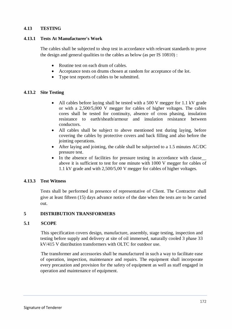
172
Signature of Tenderer
4.13 TESTING
4.13.1 Tests At Manufacturer's Work
The cables shall be subjected to shop test in accordance with relevant standards to prove
the design and general qualities to the cables as below (as per IS 10810) :
Routine test on each drum of cables.
Acceptance tests on drums chosen at random for acceptance of the lot.
Type test reports of cables to be submitted.
4.13.2 Site Testing
All cables before laying shall be tested with a 500 V megger for 1.1 kV grade
or with a 2,500/5,000 V megger for cables of higher voltages. The cables
cores shall be tested for continuity, absence of cross phasing, insulation
resistance to earth/sheath/armour and insulation resistance between
conductors.
All cables shall be subject to above mentioned test during laying, before
covering the cables by protective covers and back filling and also before the
jointing operations.
After laying and jointing, the cable shall be subjected to a 1.5 minutes AC/DC
pressure test.
In the absence of facilities for pressure testing in accordance with clause__
above it is sufficient to test for one minute with 1000 V megger for cables of
1.1 kV grade and with 2,500/5,00 V megger for cables of higher voltages.
4.13.3 Test Witness
Tests shall be performed in presence of representative of Client. The Contractor shall
give at least fifteen (15) days advance notice of the date when the tests are to be carried
out.
5 DISTRIBUTION TRANSFORMERS
5.1 SCOPE
This specification covers design, manufacture, assembly, stage testing, inspection and
testing before supply and delivery at site of oil immersed, naturally cooled 3 phase 33
kV/415 V distribution transformers with OLTC for outdoor use.
The transformer and accessories shall be manufactured in such a way to facilitate ease
of operation, inspection, maintenance and repairs. The equipment shall incorporate
every precaution and provision for the safety of equipment as well as staff engaged in
operation and maintenance of equipment.

173
Signature of Tenderer
5.2 STANDARDS
The materials shall conform in all respects to the relevant Indian/International
Standards, with latest amendments thereof unless otherwise specified herein. Some of
them are listed below:
Indian
Standard
Title
IS -2026 Specification for Power Transformers
IS - 1180 Outdoor distribution Transformer up to and including 100 kVA
IS 12444 Specification for Copper wire rod
IS-335 Specification for Transformer Oil
IS – 2099 Specification for high voltage porcelain bushing
IS - 649 Testing for steel sheets and strips and magnetic circuits
IS - 4257 Dimensions for clamping arrangements for bushings
IS - 7421 Specification for Low Voltage bushings
IS - 3347 Specification for Outdoor Bushings
IS - 9335 Specification for Insulating Kraft Paper
IS - 1576 Specification for Insulating Press Board
IS - 6600 Guide for loading of oil Immersed Transformers
IS - 6160 Rectangular Electrical conductor for electrical machines
IS - 5561 Electrical power connector
IS - 6103 Testing of specific resistance of electrical insulating liquids
IS - 6792 Determination of electrical strength of insulating oil
IS - 10028 Installation and maintenance of transformers.
Material conforming to other internationally accepted standards, which ensure equal
or better quality than the standards mentioned above, would also be acceptable. In
case the bidders who wish to offer material conforming to other standards, the bidder
shall clearly bring out the salient points of difference between the standards adopted
and the specific standards in relevant schedule.

174
Signature of Tenderer
5.3 SERVICE CONDITIONS
The Distribution Transformers to be supplied against this Specification shall be
suitable for satisfactory continuous operation under the following climatic conditions
as per IS 2026 (Part - I).
Location : At Sector 145, Noida
Maximum ambient air temperature (0C) : 50
Minimum ambient air temperature (0C) : -5
Maximum average daily ambient air temperature (0C) : 40
Maximum yearly weighted average ambient temperature(0C): 32
Note:
1. The climatic conditions specified above are indicative and can be changed by
the user as per requirements.
2. The equipment shall generally be for use in moderately hot and humid tropical
climate, conducive to rust and fungus growth unless otherwise specified.
5.4 PRINCIPAL PARAMETERS:
The transformers shall be suitable for outdoor installation with three phase, 50 Hz, 33
kV system in which the neutral is effectively earthed and they should be suitable for
service with fluctuations in supply voltage upto plus 12.5% to minus 12.5%.
The transformers shall conform to the following specific parameters:
Sl. No. Item 33 kV Distribution Transformers
1 System voltage (max.) 36 kV
2 Rated voltage HV 33 kV
3 Rated voltage LV 415 V
4 Frequency 50 Hz +/- 5%
5 No. of Phases Three
6 Connection HV Delta
7 Connection LV Star (Neutral brought out)

175
Signature of Tenderer
8 Vector group Dyn-11
9 Type of cooling ONAN
10 Audible sound levels (db) As per NEMA Standards
5.5 CORE MATERIAL
The core shall be stack / wound type of high grade cold rolled grain oriented (CRGO)
M4 prime grade or better annealed steel lamination having low loss and good grain
properties, coated with ceramic insulation, lap jointed firmly to prevent vibration or
noise. The transformer shall be boltless core design. The core shall be stress relieved
by annealing under inert atmosphere, if required. The complete design of core must
ensure permanency of the core loss with continuous working of the transformers. The
value of the maximum flux density allowed in the design and grade of lamination used
shall be clearly stated in the offer.
Transformer manufacturer shall have in-house core cutting facility for proper control
and monitoring of quality & to avoid mixing of Prime core with second
grade/defective core material.
Stage inspection of core shall be done at manufacturer premise with following
documents:
a. Invoice of Supplier
b. Mill’s test certificate
c. Bill of Landing & Bill of Entry by Customs
The transformers core shall be suitable for over fluxing (due to combined effect of
voltage and frequency) up to 10% without injurious heating at full load conditions and
shall not get saturated. The bidder shall furnish necessary design data in support of
this situation.
No-load current shall not exceed 3% of full load current and will be measured by
energising the transformer at 415 volts, 50 Hz on the secondary. Increase of voltage of
415 volts by 12.5% shall not increase the no-load current by 6% (maximum) of full
load current.
5.6 WINDINGS
a. HV and LV windings shall be wound from Super Enamel covered / Double
Paper covered 99.9% pure electrolytic grade copper conductor/foil winding.
b. Windings shall be subjected to shrinking and seasoning process so that no
further shrinkage occurs during service. Adjustable devices shall be provided
for taking up possible shrinkages.
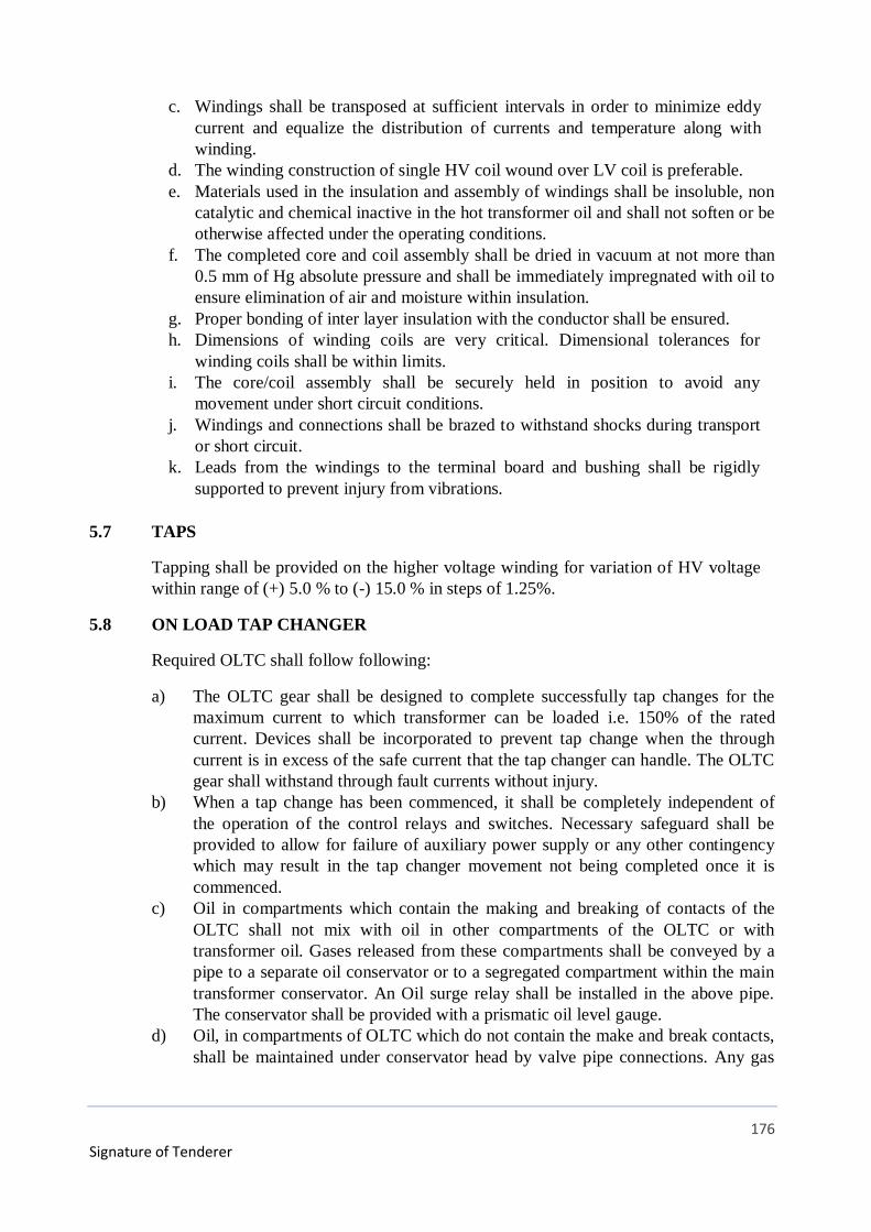
176
Signature of Tenderer
c. Windings shall be transposed at sufficient intervals in order to minimize eddy
current and equalize the distribution of currents and temperature along with
winding.
d. The winding construction of single HV coil wound over LV coil is preferable.
e. Materials used in the insulation and assembly of windings shall be insoluble, non
catalytic and chemical inactive in the hot transformer oil and shall not soften or be
otherwise affected under the operating conditions.
f. The completed core and coil assembly shall be dried in vacuum at not more than
0.5 mm of Hg absolute pressure and shall be immediately impregnated with oil to
ensure elimination of air and moisture within insulation.
g. Proper bonding of inter layer insulation with the conductor shall be ensured.
h. Dimensions of winding coils are very critical. Dimensional tolerances for
winding coils shall be within limits.
i. The core/coil assembly shall be securely held in position to avoid any
movement under short circuit conditions.
j. Windings and connections shall be brazed to withstand shocks during transport
or short circuit.
k. Leads from the windings to the terminal board and bushing shall be rigidly
supported to prevent injury from vibrations.
5.7 TAPS
Tapping shall be provided on the higher voltage winding for variation of HV voltage
within range of (+) 5.0 % to (-) 15.0 % in steps of 1.25%.
5.8 ON LOAD TAP CHANGER
Required OLTC shall follow following:
a) The OLTC gear shall be designed to complete successfully tap changes for the
maximum current to which transformer can be loaded i.e. 150% of the rated
current. Devices shall be incorporated to prevent tap change when the through
current is in excess of the safe current that the tap changer can handle. The OLTC
gear shall withstand through fault currents without injury.
b) When a tap change has been commenced, it shall be completely independent of
the operation of the control relays and switches. Necessary safeguard shall be
provided to allow for failure of auxiliary power supply or any other contingency
which may result in the tap changer movement not being completed once it is
commenced.
c) Oil in compartments which contain the making and breaking of contacts of the
OLTC shall not mix with oil in other compartments of the OLTC or with
transformer oil. Gases released from these compartments shall be conveyed by a
pipe to a separate oil conservator or to a segregated compartment within the main
transformer conservator. An Oil surge relay shall be installed in the above pipe.
The conservator shall be provided with a prismatic oil level gauge.
d) Oil, in compartments of OLTC which do not contain the make and break contacts,
shall be maintained under conservator head by valve pipe connections. Any gas

177
Signature of Tenderer
leaving these compartments shall pass through the Buchholz relay before entering
the conservator.
e) Oil filled compartments shall be provided with filling plug, drain valve with plug,
air release vent, oil sampling device, inspection opening with gasketed and bolted
cover with lifting handles.
f) OLTC driving mechanism and its associated control equipment (local) shall be
mounted in an outdoor, weatherproof cabinet with IP 55 protection which shall
Include:
Driving motor (415V, 3-phase, 50 Hz. AC squirrel cage).
Motor starting contactor with Motor Protection Circuit Breaker, isolating switch
and HRC fuses.
Control switch: Raise/off/lower (spring return to normal type).
Remote/local selector switch (maintained contact type).
Mechanical tap position indicator showing rated tap voltage against each position
and resettable maximum and minimum indicators.
Limit switches to prevent motor over-travel in either direction and final
mechanical stops.
Brake or clutch to permit only one tap change at a time on manual operation.
Emergency manual operating device (hand crank or hand wheel).
A five digit operation counter.
Electrically interlocked reversing contactors (preferably also mechanically
interlocked).
240V, 50 Hz. AC space heater with switch and HRC fuses.
Interior lighting fixture with lamp door switch and HRC fuses.
Gasketed and hinged door with locking arrangement.
Terminal blocks, internal wiring, earthing terminals and cable glands for power
and control cables.
Necessary relays, contactors, current transformers etc.
g) The following electrical control features shall be provided:
Positive completion of load current transfer, once a tap change has been initiated,
without stopping on any intermediate position, even in case of failure of external
power supply.
Only one tap change from each tap change impulse even if the control switches or
push button is maintained in the operated position.
Cut-off of electrical control when manual control is resorted to. Cut-off of a
counter impulse for a reverse tap change until the mechanism comes to rest and
resets the circuits for a fresh operation.
Cut-off of electrical control when it tends to operate the tap beyond its extreme
position.
h) Automatic OLTC control shall include the following items:
Voltage setting device.
Voltage sensing and voltage regulating devices.
Line drop compensator with adjustable R and X elements.
Line drop compensator with adjustable R and X elements.
178
Signature of Tenderer
Timer 5-25 seconds for delaying the operation of the tap changer in the first step
for every tap change operation.
Adjustable dead band for voltage variation.
i) OLTC Panel
The OLTC remote control equipment shall be suitable for 30V DC supply and
shall be housed in an indoor sheet cubicle to be located in a remote control room.
The OLTC control panel shall comprise of rigid welded structural frames made of
structural steel section or of pressed and formed cold rolled steel (CRCA) and
frame enclosures, doors and partitions shall be of cold rolled steel of thickness 2
mm. Stiffeners shall be provided wherever necessary. All doors, removable covers
and plate shall be gasketted all around with neoprene/EDPM gaskets. Panel shall
be dust, weather and vermin proof providing degree of protection of IP42, colour
of finish shade for interior and exterior shall be Powder Coated RAL7032/7035.
Earthing bus shall be of 25 x 6 mm copper.
Control switch: Raise/Off/Lower (spring return to normal type)
Auto/manual selector switch: (Maintained contact type)
Tap position indicator:
a. Facia type alarm annunciator with “accept” and “lamp test” facilities:
A.C. supply failure
Drive motor auto tripped
Tap change delayed
b. Necessary auxiliary relays
c. Lamp indications for:
1) Tap change in progress
2) Lower limit reached
3) Upper Limit reached
4) Cable glands for power and control cables
5) 240 V rated panel space heater with ON-OFF switch
6) Fluorescent type interior lighting fixture with lamp and door switch
7) HRC fuses
8) Terminal blocks
9) Internal wiring
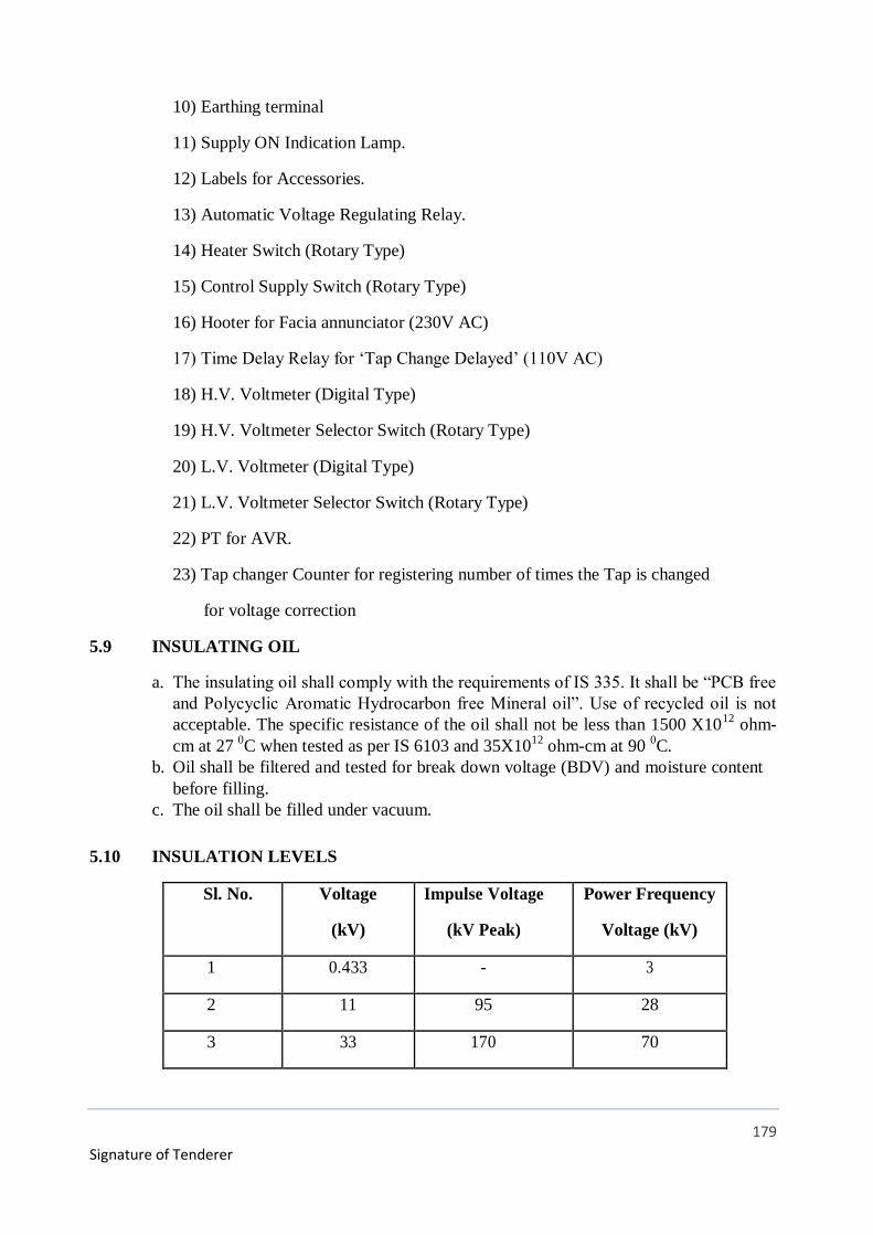
179
Signature of Tenderer
10) Earthing terminal
11) Supply ON Indication Lamp.
12) Labels for Accessories.
13) Automatic Voltage Regulating Relay.
14) Heater Switch (Rotary Type)
15) Control Supply Switch (Rotary Type)
16) Hooter for Facia annunciator (230V AC)
17) Time Delay Relay for ‘Tap Change Delayed’ (110V AC)
18) H.V. Voltmeter (Digital Type)
19) H.V. Voltmeter Selector Switch (Rotary Type)
20) L.V. Voltmeter (Digital Type)
21) L.V. Voltmeter Selector Switch (Rotary Type)
22) PT for AVR.
23) Tap changer Counter for registering number of times the Tap is changed
for voltage correction
5.9 INSULATING OIL
a. The insulating oil shall comply with the requirements of IS 335. It shall be “PCB free
and Polycyclic Aromatic Hydrocarbon free Mineral oil”. Use of recycled oil is not
acceptable. The specific resistance of the oil shall not be less than 1500 X1012
ohm-
cm at 27 0C when tested as per IS 6103 and 35X10
12 ohm-cm at 90
0C.
b. Oil shall be filtered and tested for break down voltage (BDV) and moisture content
before filling.
c. The oil shall be filled under vacuum.
5.10 INSULATION LEVELS
Sl. No.
Voltage
(kV)
Impulse Voltage
(kV Peak)
Power Frequency
Voltage (kV)
1 0.433 - 3
2 11 95 28
3 33 170 70

180
Signature of Tenderer
5.11 LOSSES
The bidder shall guarantee individually the no-load loss and load loss without any
positive tolerance. The bidder shall also guarantee the total losses at 50% and 100%
load condition (at rated voltage and frequency and at 75 0C).
The maximum allowable losses at rated voltage and rated frequency permitted at 75 0C for 33/0.415 kV transformers shall be as per energy efficiency level-II specified in
IS:1180 (Part-1) 2014 and tabulated below for reference:
Voltage
Ratio
Rating
(kVA)
Max. Losses at 50%
Loading (Watts)
Max. Losses at
100% Loading
(Watts)
33000/415 V 1250 3547.5 9890.0
33000/415 V 1600 4515.0 12685.0
Where actual losses during testing are found in excess of maximum guaranteed figures,
the transformer shall be rejected.
Measurement of losses shall form part of the routine acceptance test. The losses of first
and subsequent transformers supplied shall also be guaranteed at the time of pre
commissioning test and losses exceeding guaranteed figures shall stand rejected.
5.12 PERCENTAGE IMPEDANCE
The value of impedance of transformers at 75 0C shall be in accordance with IS 2026.
5.13 TEMPERATURE RISE
The temperatures rise over ambient shall not exceed the limits given below:
Top oil temperature rise measured by thermometer : 35 0C
Winding temperature rise measured by resistance method : 40 0C
The transformer shall be capable of giving continuous rated output without exceeding
the specified temperature rise. Bidder shall submit the calculation sheet in this regard.
5.14 TANK
The internal clearance of tank shall be such, that it shall facilitate easy lifting of core
with coils from the tank without dismantling LV bushings.
All joints of tank and fittings shall be oil tight and no bulging should occur during
service.
Inside of tank shall be painted with varnish/hot oil resistant paint.
The top cover of the tank shall be slightly sloping to drain rain water.

181
Signature of Tenderer
The tank plate and the lifting lugs shall be of such strength that the complete
transformer filled with oil may be lifted by means of lifting shackle.
Manufacturer should carry out all welding operations as per the relevant ASME
standards and submit a copy of the welding procedure to the customer.
The transformer tank shall be of robust construction rectangular/octagonal/round/
elliptical in shape and shall be built up of electrically tested welded mild steel plates
of thickness of 6 mm for the bottom and top and not less than 4 mm for the sides for
distribution transformers above 100 kVA. Tolerances as per IS:1852 shall be
applicable.
Tank shall be designed to permit lifting by crane or jacks.
In case of rectangular tanks above 100 kVA the corners shall be fully welded at the
corners from inside and outside of the tank to withstand a pressure of 0.8 kg/cm2 for
30 minutes.
Under operating conditions the pressure generated inside the tank should not exceed
0.4 kg/ sq. cm positive or negative. There must be sufficient space from the core to
the top cover to take care of oil expansion. The space above oil level in the tank shall
be filled with dry air or nitrogen conforming to commercial grade of IS:1747.
The tank shall be reinforced by welded flats on all the outside walls on the edge of the
tank.
The tank shall be capable of withstanding a pressure of 0.8 kg/ sq.cm (g) and a
vacuum of 0.7 kg/sq.cm (g) without any deformation.
The radiators can be tube type or fin type or pressed steel type to achieve the desired
cooling to limit the specified temperature rise.
5.15 CONSERVATOR
The conservator shall be provided on transformers.
When a conservator is provided, oil gauge and the plain or dehydrating breathing
device shall be fitted to the conservator which shall also be provided with a drain plug
and a filling hole normal size thread with cover. In addition, the cover of the main tank
shall be provided with an air release plug.
The dehydrating agent shall be silica gel. The moisture absorption shall be indicated
by a change in the colour of the silica gel crystals which should be easily visible from
a distance. Volume of breather shall be suitable for 1 Kg of silicagel conforming to
IS:3401 for transformers above 200 kVA.
The capacity of a conservator tank shall be designed keeping in view the total quantity
of oil and its contraction and expansion due to temperature variations. The total
volume of conservator shall be such as to contain10% quantity of the oil. Normally
3% quantity the oil shall be contained in the conservator.

182
Signature of Tenderer
The cover of main tank shall be provided with an air release plug to enable air trapped
within to be released, unless the conservator is so located as to eliminate the
possibility of air being trapped within the main tank.
The inside diameter of the pipe connecting the conservator to the main tank should be
within 20 to 50 mm and it should be projected into the conservator so that its end is
approximately 20 mm above the bottom of the conservator so as to create a sump for
collection of impurities. The minimum oil level (corresponding to -5 0C) should be
above the sump level.
5.16 SURFACE PREPARATION AND PAINTING
a. All paints, when applied in a normal full coat, shall be free from runs, sags,
wrinkles, patchiness, brush marks or other defects.
b. All primers shall be well marked into the surface, particularly in areas where
painting is evident and the first priming coat shall be applied as soon as possible
after cleaning. The paint shall be applied by airless spray according to
manufacturer’s recommendations.
5.16.1 CLEANING AND SURFACE PREPARATION:
a. After all machining, forming and welding has been completed, all steel work
surfaces shall be thoroughly cleaned of rust, scale, welding slag or spatter and other
contamination prior to any painting.
b. Steel surfaces shall be prepared by shot blast cleaning (IS9954) to grade Sq. 2.5 of
ISO 8501-1 or chemical cleaning including phosphating of the appropriate quality
(IS 3618).
c. Chipping, scraping and steel wire brushing using manual or power driven tools
cannot remove firmly adherent mill-scale. These methods shall only be used where
blast cleaning is impractical. Manufacturer to clearly explain such areas in his
technical offer.
5.16.2 PROTECTIVE COATING
As soon as all items have been cleaned and within four hours of the subsequent
drying, they shall be given suitable anti-corrosion protection.
5.16.3 PAINT MATERIAL
a. Following are the types of paint which may be suitably used for the items to be
painted at shop and supply of matching paint to site:
i. Heat resistant paint (Hot oil proof) for inside surface
183
Signature of Tenderer
b. For external surfaces one coat of thermo setting powder paint or one coat of epoxy
primer followed by two coats of synthetic enamel/polyurethene base paint. These
paints can be either air drying or stoving.
5.16.4 PAINTING PROCEDURE
a. All prepared steel surfaces should be primed before visible re-rusting occurs or
within 4 hours, whichever is sooner. Chemical treated steel surfaces shall be primed
as soon as the surface is dry and while the surface is still warm.
b. Where the quality of film is impaired by excess film thickness (wrinkling, mud
cracking or general softness) the supplier shall remove the unsatisfactory paint
coating and apply another coating. As a general rule, dry film thickness should not
exceed the specified minimum dry film thickens by more than 25%.
5.16.5 DRY FILM THICKNESS
a. To the maximum extent practicable, the coats shall be applied as a continuous
film of uniform thickness and free of pores. Overspray, skips, runs, sags and
drips should be avoided. The different coats may be of the same colour.
b. Each coat of paint shall be allowed to harden before the next is applied as per
manufacturer’s recommendation.
c. Particular attention must be paid to full film thickness at the edges.
d. The requirements for the dry film thickness (DFT) of paint and the materials to
be used shall be as given below:
Sl.
No.
Paint Type Area to be
painted
No. of
coats
Total dry film
thickness
(DFT) (Min.)
(Micron)
1 Thermo setting powder paint Inside 01 30
Outside 01 60
2 Liquid paint
a. Epoxy primer Outside 01 30
b. PU paint (Finish coat) Outside 02 25 each
c. Hot oil paint/varnish Inside 01 35/10

184
Signature of Tenderer
5.16.6 TESTS FOR PAINTED SURFACE
a. The painted surface shall be tested for paint thickness.
b. The painted surface shall pass the cross hatch adhesion test and impact test as
acceptance tests and Salt spray test and Hardness test as type test as per the relevant
ASTM standards.
Note: Supplier shall guarantee the painting performance requirement for a period of
not less than 5 years.
5.17 BUSHINGS
a. The bushings shall conform to the relevant standards specified and shall be of
outdoor type. The bushing rods and nuts shall be made of brass material 12
diameter for both HT and LT bushings. The bushings shall be fixed to the
transformers on side with straight pockets and in the same plane or the top cover
for transformers above 100 kVA. The tests as per latest IS 2099 and IS 7421
shall be conducted on the transformer bushings.
b. For 33 kV, 52 kV class bushings shall be used for transformers of ratings above
500 kVA.
c. Bushing can be of porcelain/epoxy material. Polymer insulator bushings
conforming to relevant IEC can also be used.
d. Dimensions of the bushings of the voltage class shall conform to the Standards
specified and dimension of clamping arrangement shall be as per IS 4257
e. Minimum external phase to phase and phase to earth clearances of bushing
terminals shall be as follows:
Voltage Clearance
Phase to phase (mm) Phase to earth (mm)
33 kV 350 320
11 kV 255 140
LV 75 40
The clearances in case of cable box shall be as below:
Voltage Clearance
Phase to phase (mm) Phase to earth (mm)
33 kV 351 222
11 kV 127 76
LV 45 20
185
Signature of Tenderer
f. Arcing horns shall be provided on HV bushings.
g. Brazing of all inter connections, jumpers from winding to bushing shall have
cross section larger than the winding conductor. All the Brazes shall be
qualified as per ASME, section – IX.
h. The bushings shall be of reputed make supplied by those manufacturers who are
having manufacturing and testing facilities for insulators.
5.18 CABLE BOXES
a. In case HV/LV terminations are to be made through cables the transformer shall
be fitted with suitable cable box on 33 kV side to terminate one 33kV/ 3 core
aluminium conductor cable up to 240 sq. mm.(Size as per requirement). The
bidder shall ensure the arrangement of HT Cable box so as to prevent the ingress
of moisture into the box due to rain water directly falling on the box. The cable
box on HT side shall be of the split type with faces plain and machined and
fitted with Neo-k-Tex or similar quality gasket and complete with brass wiping
gland to be mounted on separate split type gland plate with nut-bolt arrangement
and MS earthing clamp. The bushings of the cable box shall be fitted with nuts
and stem to take the cable cores without bending them. The stem shall be of
copper with copper nuts. HT Cable support clamp should be provided to avoid
tension due to cable weight.
b. When bus duct connection is specified, a flanged bushing connection shall be
provided to suit the client bus duct. The winding termination shall be brought
out on outdoor type bushing.
5.19 TERMINAL MARKINGS
High voltage phase windings shall be marked both in the terminal boards inside the
tank and on the outside with capital letter 1U, 1V, 1W and low voltage winding for
the same phase marked by corresponding small letter 2u, 2v, 2w. The neutral point
terminal shall be indicated by the letter 2n. Neutral terminal is to be brought out and
connected to local grounding terminal by an earthing strip.
5.20 FITTINGS
The following standard fittings shall be provided:
I. Diagram, Rating and terminal marking plates, non-detachable.
II. Earthing terminals with lugs - 2 Nos.
III. Lifting lugs for main tank and top cover
IV. Terminal connectors on the HV/LV bushings (For bare terminations only).
V. Thermometer pockets with cap
VI. 150 mm dial type winding temperature indicator with maximum reading pointer
and alarm & trip contacts
VII. 150 mm dial type oil temperature indicator with maximum reading pointer and
alarm & trip contacts
186
Signature of Tenderer
VIII. 150 mm dial type magnetic oil level indicator with low level alarm and trip
contacts and minimum & maximum filling level markings
IX. Double float Buckholz relay with alarm and trip contacts
X. W.P. thermo junction box
XI. Oil surge relay for OLTC
XII. Shut off valve for OLTC connection
XIII. Air release device
XIV. HV bushings - 3 Nos.
XV. LV bushings - 4 Nos.
XVI. Pulling lugs
XVII. Stiffener
XVIII. Detachable radiator with top and bottom stop valves and drain & air release
plugs
XIX. Radiators - No. and length may be mentioned (as per heat dissipation
calculations)/ corrugations.
XX. Arcing horns or 9 kV, 5 kA lightning arrestors on HT side - 3 No.
XXI. Prismatic oil level gauge.
XXII. Drain cum sampling valve.
XXIII. Top filter valve
XXIV. Oil filling hole having p. 1- ¼ ‘’ thread with plug and drain plug on the
conservator.
XXV. Silica gel breather
XXVI. 4 No. rollers for transformers of 200 kVA and above.
XXVII. Pressure relief device or double diaphragm explosion vent.
XXVIII. Extra neutral bushing for solid earthling
XXIX. Neutral CT with terminals brought out for connection
5.21 FASTENERS
a. All bolts, studs, screw threads, pipe threads, bolt heads and nuts shall comply
with the appropriate Indian Standards for metric threads, or the technical
equivalent.
b. Bolts or studs shall not be less than 6 mm in diameter except when used for small
wiring terminals.
c. All nuts and pins shall be adequately locked.
d. Wherever possible bolts shall be fitted in such a manner that in the event of
failure of locking, resulting in the nuts working loose and falling off, the bolt will
remain in position.
e. All ferrous bolts, nuts and washers placed in outdoor positions shall be treated to
prevent corrosion, by hot dip galvanising, except for high tensile steel bolts and
spring washers which shall be electro-galvanised/plated. Appropriate precautions
shall be taken to prevent electrolytic action between dissimilar metals.
f. Taper washers shall be provided where necessary.

187
Signature of Tenderer
g. Protective washers of suitable material shall be provided in front and back of the
securing screws.
5.22 OVERLOAD CAPACITY
The transformers shall be suitable for loading as per IS 6600.
5.23 PROTECTION FEATURES
Expulsion/any other suitable type of fuse shall be placed in series with the primary
winding. This fuse is mounted normally inside of the primary bushing for the three
phases and is connected to the high voltage winding through a terminal block. This
has to protect that part of the electrical distribution system which is ahead of the
distribution transformers from faults which occur inside the distribution transformer
i.e., either in the windings or some other part of the transformer. It shall be ensured
that this fuse does not blow for faults on the secondary side (LT side) of the
transformer i.e., the blowing characteristics of the fuse and LT breaker shall be so
coordinated such that the fuse shall not blow for any faults on the secondary side of
the transformer beyond LT breakers and those faults shall be cleared by the LT
breaker only.
5.24 TESTS
a. Transformers shall be subjected to routine and type tests as specified in IS:2026, IS:
11171 and IEC: 726 as given below.
b. All the equipment offered shall be fully type tested by the bidder or his collaborator
as per the relevant standards including the additional type tests. The type test must
have been conducted on a transformer of same design during the last five years at
the time of bidding.
c. Before dispatch, each of the completely assembled transformers shall be subjected to
the routine tests at the manufacturer’s works.
5.24.1 ROUTINE TESTS
a. Ratio, polarity, phase sequence and vector group.
b. No Load current and losses at service voltage and normal frequency.
c. Load losses at rated current and normal frequency.
d. Impedance voltage test.
e. HV & LV winding resistance
f. Measurement of load losses at 50%, 75% and 100%
g. Insulation resistance test
h. Induced over voltage withstand test.
i. Separate source voltage withstand test.
j. Neutral current measurement-The value of zero sequence current in the neutral of
the star winding shall not be more than 2% of the full load current.
k. Oil samples to comply with IS 1866.

188
Signature of Tenderer
5.24.2 TYPE TESTS
In addition to the tests mentioned in clause 5.24.1, following tests shall be conducted:
a. Temperature rise test to be conducted for each rating for determining the maximum
temperature rise after continuous full load run. The ambient temperature and time of
test should be stated in the test certificate.
b. Impulse voltage withstand test
c. Short circuit withstand test, Thermal and dynamic ability.
d. Noise-level measurement.
e. Leakage test (Tank)
f. Pressure relief device test: The pressure relief device shall be subject to increasing
fluid pressure. It shall operate before reaching the test pressure as specified in the
above class. The operating pressure shall be recorded. The device shall seal-off after
the excess pressure has been released.
5.25 TESTS AT SITE
The purchaser reserves the right to conduct all tests on transformer after arrival at site
and the manufacturer shall guarantee test certificate figures under actual service
conditions.
5.26 INSPECTION AND TESTING
a. The Contractor shall draw up and carry out comprehensive Inspection and
Testing Program during manufacturing and commissioning of the transformer.
The program shall be duly approved by client.
b. To ascertain the quality of the transformer oil, the original manufacturer’s tests
report should be submitted at the time of inspection. Arrangements should also
be made for testing of transformer oil, after taking out the sample from the
manufactured transformers and tested in the presence of client’s representative.
c. To ensure about the quality of transformers, the inspection shall be carried out
by the client’s representative at following two stages:-
i. Online anytime during receipt of raw material and manufacture/ assembly
whenever the client desires.
ii. At finished stage i.e. transformers are fully assembled and are ready for
dispatch.
d. In case of any defect/defective workmanship observed at any stage by the
pclient’s Inspecting Officer, the same shall be pointed out to the firm in writing
for taking remedial measures. Further processing should only be done after
clearance from the Inspecting Officer/ purchaser.
e. All tests and inspection shall be carried out at the place of manufacture unless
otherwise specifically agreed upon by the manufacturer and purchaser at the
time of purchase. The manufacturer shall offer the Inspector representing the
client all reasonable facilities, without charges, to satisfy him that the material
is being supplied in accordance with this specification. This will include Stage

189
Signature of Tenderer
Inspection during manufacturing stage as well as Active Part Inspection during
Acceptance Tests.
f. The manufacturer shall provide all services to establish and maintain quality of
workman ship in his works and that of his sub-contractors to ensure the
mechanical /electrical performance of components, compliance with drawings,
identification and acceptability of all materials, parts and equipment as per
latest quality standards of ISO 9000.
g. The client has the right to have the test carried out at his own cost by an
independent agency wherever there is a dispute regarding the quality supplied.
Purchaser has right to test the supply selected either from the stores or field to
check the quality of the product. In case of any deviation, purchaser has every
right to reject the entire lot or penalize the manufacturer, which may lead to
blacklisting, among other things.
5.27 DRAWING AND INFORMATION
The vendor shall furnish following drawings/documents in accordance with enclosed
requirements:
a. General arrangement of transformer
b. General arrangement of HV cable box with connection diagram
c. General arrangement of LV bus duct and connection diagram
d. General arrangement of marshaling box and wiring diagram
e. Rating and diagram plate indicating % impedance etc.
f. Guaranteed technical parameters
g. Reactance, resistance and capacitance
h. Initial charging current (in-rush current)
5.28 PACKING AND FORWARDING
i. The packing shall be done as per the manufacturer’s standard practice.
However, it should be ensured that the packing is such that, the material
would not get damaged during transit by Rail / Road / Sea.
ii. The marking on each package shall be as per the relevant IS.
5.29 GUARANTEE
The manufacturers of the transformer shall provide a guarantee of 24 months from the
date of receipt at site or 18 months from the date of commissioning, whichever is
earlier. In case the distribution transformer fails within the guarantee period, the client
will immediately inform the supplier who shall take back the failed DT within 7
(Seven) days from the date of the intimation at his own cost and replace/repair the
transformer within 30 (Thirty) days of date of intimation with a roll over guarantee.
The outage period i.e. period from the date of failure till unit is repaired/ replaced
shall not be counted for arriving at the guarantee period.
190
Signature of Tenderer
In the event of the supplier’s inability to adhere to the aforesaid provisions, suitable
penal action will be taken against the supplier which may inter alia include
blacklisting of the firm for future business with the client for a certain period.
5.30 DEVIATION
Deviation from specifications must be stated in writing at the tendering stage. In the
absence of such statement, it will be assumed that the requirements of the specifications
are met without exception.
6 LOW VOLTAGE PANEL & SWITCHGEAR
This section covers specification of Medium Voltage Switchboards incorporating items
of switchgear like Circuit Breakers, MCCBs, metering and protection
6.1 GENERAL
6.1.1 STANDARDS AND CODES
The following Indian Standard Specifications and Codes of Practice will apply to the
equipment and the work covered by the scope of this contract. In addition the relevant
clauses of the Indian Electricity Act 1910 and Indian Electricity Rules 2003 as amended
upto date shall also apply. Wherever appropriate Indian Standards are not available,
relevant British and/or IEC Standards shall be applicable.
BIS certified equipment shall be used as a part of the Contract in line with Government
regulations. Necessary test certificates in support of the certification shall be submitted
prior to supply of the equipment.
It is to be noted that updated and current Standards shall be applicable irrespective of
those listed below.
IEC 61439-1&2 : Low Voltage Switchgear Assemblies
IEC 60947/IS 13947:1993 : Low Voltage Switchgear & Control Gear
IEC 60529/IS 2147:1962 : Degree of Protection of Enclosures for LV
Switchgear
IEC 61641 : Internal Arc
IS 11353 : 1985 : Marking of Switchgear Busbars
IS 3231:1986 : Electrical Relays for Power System
Protection

191
Signature of Tenderer
6.1.2 TYPE OF PANEL
The medium voltage switch board panel shall comprise of the following type of
switchgears:
a. Air Circuit breakers draw out type.
b. Plug-in type MCCBs of suitable Ics ratings. MCCBs shall invariably be
Current Limiting type. Features like Double Break, Positive Isolation
functions shall be preferred.
The Panel shall be indoor type having incoming sectionalization and outgoing
switchgears as specified. The design shall be cubical type. The degree of enclosure
protection shall be IP 42.
6.1.3 SITE CONDITIONS
For general climatic conditions, refer and comply the specified project site conditions.
The main distribution boards shall comply and perform satisfactorily at the below listed
special design conditions as minimum:
Ambient temperature : 45ºC
Relative humidity : 95% (at 55ºC)
6.2 LT PANEL
The main LT panel shall be total type tested assembly as per standards IEC: 61439-1&2.
Main LT Panel shall be supplied as per BOQ, specifications & drawings (SLD). LT
Panel shall be indoor type, IP 42, metal clad, floor mounted, free standing, totally
enclosed, extensible type, air insulated, cubicle type for use on 415 Volts, 3 phase, 50
cycles system with a fault level of 50 kA RMS symmetrical, with bus coupler switching
& interlocking of incomer & bus coupler breakers of Main LT Panel.
All medium voltage switchboards shall be suitable for operation at three
phase/three phase 4 wire, neutral grounded at transformer system as per schedule
of quantities and insulation voltage of 1000 V.
The switchboards and the associated equipment including switchgear, control
gear, Busbar supports, Busbar orientation, Busbar links etc shall be identical in
construction to the assembly which has undergone the type test. The drawings of
the type-tested assemblies shall be made available for inspection. The drawings
shall be signed and stamped by OEM for verification of GA and bus bar sizing.
The enclosures shall be designed to take care of normal stress as well as
abnormal electro-mechanical stress due to short circuit conditions. All covers
and doors provided shall offer adequate safety to operating persons and provide
ingress protection of IP 42 unless otherwise stated. Ventilating openings and
vent outlets, if provided, shall be arranged such that same ingress protection of
192
Signature of Tenderer
IP 42 is retained. Suitable pressure relief devices shall be provided to minimize
danger to operator during internal fault conditions.
The switchboard along with ACBs and connections should have been be total
type tested design at CPRI/ERDA for short circuit, temperature rise, protective
earth short circuit test and dielectric tests of the ratings required .
For operator safety IP2X (touch proof) protection to be available even after
opening the feeder compartment door. The compartmentalization to be achieved
by using metal separators, use of PVC sheet / Hylem sheets shall not be allowed.
All equipment and components of the main distribution boards shall be capable
of continuous operation at their full current and voltage ratings and without
detriment or malfunction at system continuous deviation of up to and including
the following percentages of the normal values.
Voltages ± 10%
Frequency ± 5%
All components shall be capable of withstanding the dynamic, thermal and
dielectric stresses resulting from prospective short circuit currents without
damage or injury to personnel.
Main distribution boards shall be assembled only by a franchisee (Licence
Partner) of the original manufacturer and approved by the consultant. The
certificate copy issued by original manufacturer shall be attached with quotation
document for review & acceptance. All major components like enclosures,
switchgear components and bus bar supports shall be supplied by OEM
manufacturer to franchisee assembler (Licence Partner). In case of licensed
manufacture, enclosure parts may be manufactured as per drawings issued by
original manufacture with quality check. The QA documents, if required shall be
furnished for review during inspection. The QA shall be of OEM and during
inspection, OEM inspection personal shall be available along with along with
customer and consultant inspection.
Vendors shall ensure components like ACBs, MCCBs selected shall have both
current and time discrimination. Coordination study done using switchgear
manufacturer’s software shall be furnished.
6.2.1 PANEL CONFIGURATION
The Switch Board shall be configured with Air Circuit Breakers, MCCB's, and
other equipment as called for in the Schedule of Quantities.
The MCCB's shall be arranged in multi-tier formation whereas the Air Circuit
Breakers shall be arranged in Single or Double tier formation only to facilitate
operation and maintenance.
The Switch Boards shall be of adequate size with a provision of 25% spare space
to accommodate possible future additional switch gear.
193
Signature of Tenderer
6.2.2 CONSTRUCTIONAL FEATURES
The Switch Boards shall be metal enclosed, sheet steel cubicle patern,
extensible, floor mounting type and suitable for indoor mounting.
The Switch Boards shall be totally enclosed, completely dust and vermin proof.
Gaskets between all adjacent units and beneath all covers shall be provided to
render the joints dust and vermin proof to provide a degree of protection of IP
42. All doors and covers shall also be fully gasketed with PU foam/Neoprene/
EPDM rubber and shall be lockable.
The Switch Board shall be fabricated with CRCA Sheet Steel of thickness not
less than 2.0 mm and shall be folded and braced as necessary to provide a rigid
support for all components. The doors and covers shall be from CRCA sheet
steel of thickness not less than 1.5 mm. Joints of any kind in sheet metal shall be
seam welded and all welding slag ground off and welding pits wiped smooth
with plumber metal.
All panels and covers shall be properly fitted and square with the frame. The
holes in the panel shall be correctly positioned.
Switchboards construction shall employ the principle of compartmentalized and
segregation for each circuit.
Incomer and bus section panels or sections shall be separate and independent and
shall not be wired with sections required for feeder. The incomer panel shall be
suitable for receiving bus trunking or MV cable of size specified.
Switchboard shall be readily extensible on both sides by addition of vertical
sections after removal of the end covers.
The switchboards shall be designed for use in high ambient temperature and
humid tropical conditions as specified. Ease of inspections, cleaning and repairs
while maintaining continuity of operation shall be provided in the design.
Special care to be taken to ensure effective earthing of the frame and doors of the
switchboards
Each vertical section shall be provided with a rear or side cable chamber housing
the cable end connections and power/control cable terminations. There should
be generous availability of space for ease of installation and maintenance with
adequate safety for working in one vertical section without coming into contract
with any live parts. The design of the switchboard shall allow standard
extension chambers if required to accommodate cables.
Switchboard shall be provided with “Danger Notice Plate” conforming to
relevant Indian Standards.
The main LV Panel shall be able to connect to Ethernet and communicate all
related data of ACBs, MCCB, Meters etc to EMS software.
Internal arc withstand of 50kA for 0.3-0.5 sec.
194
Signature of Tenderer
6.2.3 SWITCHBOARD COMPARTMENTALIZATION
For compartmentalized switchboards, separate totally enclosed compartments
shall be provided for horizontal busbars, vertical busbars, ACBs, MCCBs, and
cable alloys.
The main board shall be with Form 4b Construction.
Earthed metal or insulated shutters shall be provided between drawout and fixed
portion of the switchgear such that no lives parts are accessible with equipment
drawn out. Degree of protection within compartments shall be atleast IP 2X.
Sheet steel hinged lockable doors for each separate compartment shall be
provided and duly interlocked with the breaker in "ON" and "OFF" position.
For all Circuit Breakers separate and adequate compartments shall be provided
for accommodating instruments, indicating lamps, control contactors and control
MCB etc. These shall be accessible for testing and maintenance without any
danger of accidental contact with live parts of the circuit breaker, busbars and
connections.
For Some MCCB feeders for critical loads like UPS it may be required to have
operation only after opening the door, all other facilities like padlockable rotary
handle to be provided for such feeder. It shall be possible to do this change
during execution of order
Each switchgear cubicles shall be fitted with label in front and back identifying
the circuit, switchgear type, rating and duty. All operating device shall be located
in front of switchgear only.
Cable compartments shall be of adequate size for easy termination of all
incoming and outgoing cables entering from bottom or top. The construction
shall include necessary and adequate and proper support shall be provided in
cable compartments to support and clamping the cable in the cable alley / cable
chamber.
6.2.4 PANEL DIMENSIONAL LIMITATIONS
A base channel 75 mm x 5 mm thick shall be provided at the bottom.
A minimum of 200 mm blank space between the floor of switch board and
bottom most unit shall be provided.
The overall height of the Switch Board shall be limited to 2400 mm
The height of the operating handle, push buttons etc shall be restricted between
300 mm and 1800 mm from finished floor level.
6.2.5 DRAW OUT FEATURES
Air Circuit Breakers shall be provided in fully drawout cubicles. These cubicles
shall be such that drawout is possible without disconnection of the wires and
cables. The power and control circuits shall have self aligning and self isolating
contacts. The fixed and moving contacts shall be easily accessible for operation
anmd maintenance. Mechanical interlocks shall be provided on the drawout
cubicles to ensure safety and compliance to relevant Standards.
195
Signature of Tenderer
The MCCB's shall be plug-in type MCCB in order to replace the MCCBs in live
condition.
6.2.6 BUS BARS
The Bus Bar and interconnections shall be of electrolytic Copper and of
rectangular cross sections suitable for full load current for phase bus bars. The
maximum current density for copper shall be 1.25 amps per sq. mm. suitable to
withstand the stresses of a 50 kA fault level at 415 volts for 1 second or as per
schedule of quantities. .
The bus bars and interconnections shall be insulated with insulation tape/ fiber
glass.
The bus bars shall be extensible on either side of the Switch Board.
The bus bars shall be supported on non-breakable, non-hygroscopic insulated
supports at regular intervals, to withstand the forces arising from a fault level of
50 kA at 415 volts for 1 second and operating temperature of 110 0C. The
material and spacing of the Busbar supports shall be same as per the type tested
assembly.
Auxiliary buses for control power supply, space heater or any other specified
services shall be provided.
Clearances between phases shall be in line with IEC.
All bus bars shall be colour coded.
All bus bar connections in Switch Boards shall be bolted with brass bolts and
nuts. Additional cross section of bus bars shall be provided wherever holes are
drilled in the bus bars.
6.2.7 PANEL INTERCONNECTIONS
All connections between the bus bars/Breakers/cable terminations shall be
through solid copper strips of adequate size to carry full rated current and
PVC/fibre glass insulated.
For unit ratings upto 100 amps FRLS insulated copper conductor wires of
adequate size to carry full load current shall be used. The terminations of all such
interconnections shall be crimped.
6.2.8 WIRING
All wiring for relays and meters shall be with FRLS insulated copper conductor wires.
The wiring shall be coded and labeled with approved ferrules for identification. The
minimum size of copper conductor control wires shall be 2.5 sq. mm. Runs of wires
shall be neatly bunched and suitably supported and clamped. Means shall be provided
for easy identification of wires. Identification ferrules shall used at both end of wires.
196
Signature of Tenderer
All control wires meant for external connections are to be brought out on a terminal
board. The cables and control wires shall be suitable for withstanding 105 deg C.
6.2.9 INSTRUMENT ACCOMMODATION
All voltmeter and ammeter and other instruments shall be flushed mounted type
conforming to accuracy class 1 to IS 1248 for accuracy. All voltmeter shall be
protected with control MCBs.
Instruments and indicating lamps shall not be mounted on the Circuit Breaker
Compartment door for which a separate and adequate compartment shall be
provided and the instrumentation shall be accessible for testing and maintenance
without danger of accidental contact with live parts of the Switchboard.
For MCCBs, instruments and indicating lamps can be provided on the
compartment doors.
The current transformers for metering and for protection shall be mounted on the
solid copper busbars with proper supports.
On all the incomers of switch boards ON/OFF indicators lamps shall be provided
suitable for operation on AC 230 volts supply. All lamps shall be protected by
control MCBs.
For Incomer and important outgoing feeders comprehensive power meters shall
be provided which shall display A, V, PF, Hz, Kw, KVA, KVAr, Kwh, Kvarh,
average and maximum values, demand values, individual harmonics on current
and Voltages. Also add on modules for RS485 port to link to
BMS/EMS/SCADA system.
6.2.10 CABLE TERMINATIONS
Knockout holes of appropriate size and number shall be provided in the Switch
Board in conformity with the location of incoming and outgoing conduits/cables.
The cable terminations of the Circuit Breakers shall be brought out to terminal
cable sockets suitably located at the rear of the panel.
The cable terminations for the MCCB's shall be brought out to the rear in the
case of rear access switchboards or in the cable compartment in the case of front
access Switch Boards.
The Switch Boards shall be complete with tinned brass cable sockets, tinned
brass compression glands, gland plates, supporting clamps and brackets etc for
termination of 1100 volt grade aluminium conductor PVC/PVCA cables.
6.2.11 SPACE HEATERS
Anti- condensation heaters shall be fitted in each cubicle together with an ON/OFF
isolating switch suitable for electrical operation at 230 volts A.C 50 Hz single phase of
sufficient capacity to raise the internal ambient temperature by 5O
C. The electrical
apparatus so protected shall be designed so that the maximum permitted rise in
197
Signature of Tenderer
temperature is not exceeded if the heaters are energized while the switchboard is in
operation. As a general rule, the heaters shall be placed at the bottom of the cubicle.
6.2.12 EARTHING
A main earth bar of G.I./copper as required shall be provided throughout the full length
of the Switch Board with a provision to make connections to the sub-station earths on
both sides.
6.2.13 SHEET STEEL TREATMENT AND PAINTING
Sheet Steel materials used in the construction of these units should have
undergone a rigorous rust proofing process comprising of alkaline degreasing,
descaling in dilute sulphuric acid and a recognised phosphating process. The
steel work shall then receive two costs of oxide filler primer before final
painting. Castings shall be scrupulously cleaned and fettled before receiving a
similar oxide primer coat.
All sheet steel shall after metal treatment be spray or powder painted with two
coats of shade 692 to IS 5 on the outside and white on the inside. Each coat of
paint shall be properly stoved and the paint thickness shall not be less than 50
microns.
6.2.14 NAME PLATES AND LABELS
Suitable engraved white on black name plates and identification labels of metal for all
Switch Boards and Circuits shall be provided. These shall indicate the feeder number
and feeder designation.
6.2.15 INSTALLATION
The foundations prepared as per the manufacturers drawings shall be leveled, checked
for accuracy and the Panel installed. All bus bar connections shall be checked with a
feeler gauge after installation. The cable end boxes shall be sealed to prevent entry of
moisture. The main earth bar shall be connected to the sub-station earths.
A 15 mm thick rubber matting of approved make on a 100 mm high timber shall be
provided in front of and along the full length of the Switch Board. The width of the
matting shall be 1000 mm. The rubber mat shall withstand 15 KV for 1 minute and
leakage current shall not exceed 160 mA/sq. metre.
After installation the Switch Board shall be tested as required prior to commissioning.

198
Signature of Tenderer
6.2.16 TESTING
6.2.16.1 TYPE TEST
The main distribution board and the components as applicable shall be type tested in
accordance with the IEC standards to verify the specified fault level withstand capacity
from a reputed and approved type testing laboratory and certified by an competent
authority.
The following type tests as specified in IEC 61439-1standards shall be carried out on
assembly at recognized test laboratories and certificates shall be provided for each type
test:
i. Verification of temperature-rise limits (IEC Cl. 10.10);
ii. Verification of the dielectric properties (IEC Cl. 10.9);
iii. Verification of short-circuit withstand strength (IEC Cl. 10.11);
iv. Verification of the effectiveness of the protective circuit (IEC Cl.10.5)
v. Verification of clearances and creep age distances (IEC C. 10.4)
vi. Verification of mechanical operation (IEC Cl.10.13)
vii. Verification of the degree of protection (IEC Clause 10.3)
viii. Verification of mechanical impact (IEC Clause 10.2)
The panel should be tested for internal arc as per IEC 61641 which guarantee safety to
operating personnel in terms of arc containment and readiness of panel for normal
operation after the clearance of fault.
Type test certificates shall be submitted to the consultant engineer for verification.
6.2.16.2 ROUTINE TEST
The panel assembler shall perform the routine test and provide the test certificates as
defined in IEC standards. The routine test shall include but not limited to the following:
1. Inspection of the assembly including inspection of wiring and electrical
operational test
2. Dielectric test & Insulation resistance test
3. Checking of protective measures and of the electrical continuity of the
protective circuits
4. Functional test as per the approved test procedure.
Routine test certificates and test readings shall be submitted to the consultant engineer
for verification.
199
Signature of Tenderer
6.2.17 TESTING & COMMISSIONING AT SITE
Commissioning checks and tests shall include all wiring checks and checking up of
connections. Relay adjustment/setting shall be done before commissioning, in addition
to routine Megger tests. Checks and tests shall include the following:
a. Operation checks and lubrication of all moving parts.
b. Interlock function checks.
c. Continuity checks of wiring, fuses etc. as required.
d. Insulation test: When measured with 500 V Megger the insulation
resistance shall not be less than 100 mega ohms.
e. Alignment of panel, interconnection of Bus bars and tightness of bolts and
connection.
f. Inter panel wiring
g. Free movement of ACB/MCCB
h. Operation of breakers
6.3 LOW VOLTAGE AIR CIRCUIT BREAKERS
6.3.1 TECHNICAL PARAMETERS
The circuit breaker shall be of the air break type, robust and compact design
suitable for indoor mounting and shall comply with the requirement of IEC:
60947-1&2. Rupturing capacity shall be 50 kA at 415 Volts or as per
schedule of quantities.
The breakers shall be type tested & certified at ERDA/CPRI.
ACB shall have a rated operational voltage of 415V AC, rated insulation
voltage of 1000 volts AC, rated impulse voltage of 12kV.
The breaker shall comply with the isolation function requirement of IEC
60947-2 section 7.12 to be marked as suitable for isolation / disconnection to
facilitate safety of operating personal while the breaker is in use.
The breaker shall provide class II insulation between the front panel and
internal power circuits to avoid any accidental contact with the live main
current carrying path with the front cover open.
Protective devices, metering, CTs, PTs, push buttons and indicating lamps
shall be provided as per schedule of quantities.
The ACBs shall be capable for LOTO (Lock Out Tag Out) protection.
ACB shall comply with the environmental directives like RoHS.
All ACBs irrespective of Incomer or Outgoing shall have neutral protection.
In case of 3P ACBs are offered based on application, it shall still be possible
to protect neutral by providing external CT.
ACB shall have the breaking performance Ics = Icu = Icw (1sec) = 50kA
200
Signature of Tenderer
6.3.2 CONSTRUCTIONAL FEATURES
The Circuit Breaker shall be flush front, metal clad, horizontal draw-out
pattern, three/four pole as required and fully interlocked. Each Circuit Breaker
shall be housed in a separate compartment enclosed on all sides.
The Circuit Breaker cradle shall be designed and constructed to permit smooth
withdrawal and insertion. The movement shall be free of jerks, easy to operate
and positive.
All current carrying parts in the breaker shall be silver plated and suitable
arcing contacts shall be provided to protect the main contacts which shall be
separate from the main contacts and easily replaceable. In addition, Arc chutes
shall be provided for each pole, and these shall be suitable for being lifted out
for the inspection of the main and the arcing contacts.
Self-aligning cluster type isolating contacts shall be provided for the Circuit
Breaker, with automatically operated shutters to screen live cluster contacts
when the Breaker is withdrawn from the cubicle. Sliding connections
including those for the auxiliary contacts and control wiring shall also be of
the self-aligning type. The fixed portion of the sliding connections shall have
easy access for maintenance purposes.
ACBs shall be capable for LOTO (Lock Out Tag Out) protection.
The cubicle for housing the Breaker shall be free standing pattern, fabricated
from the best quality sheet steel.
All ACBs shall have OEM make terminal adopters for both
incoming/outgoing side.
6.3.3 OPERATING MECHANISM
The Circuit Breaker shall be trip free with independent manual spring
operated or motor wound spring operated mechanism as specified and with
mechanical ON/OFF indication. The operating mechanism shall be such that
the circuit breaker is at all times free to open immediately the trip coil is
energised.
The closing time shall be less than or equal to 70 ms to ensure faster closing
of the breaker. And tripping time should be less than 40 ms to reduce the let
through energy in the event of fault.
The operating handle and mechanical trip push button shall be at the front of
and integral with the Circuit Breaker.
There shall be electrical indicator on the front panel for ‘Ready to close’
situation for the breaker by checking all interlockings.
The Circuit Breaker shall have the following four distinct and separate
positions which shall be indicated on the face of the panel.
201
Signature of Tenderer
"Service" -- Both main and secondary isolating contacts closed
"Test" -- Main isolating contacts open and secondary isolating contacts
closed
"Isolated" -- Both main and secondary isolating contacts open
"Maintenance" -- Circuit Breaker fully outside the panel ready for
maintenance
6.3.4 CIRCUIT BREAKER INTERLOCKING
Sequence type strain free interlocks shall be provided to ensure the following:
It shall not be possible for the Breaker to be withdrawn from the cubicle when
in the "ON" position. To achieve this, suitable mechanism shall be provided to
lock the Breaker in the tripped position before the Breaker is isolated.
It shall not be possible for the Breaker to be switched "ON" until it is either in
the fully inserted position or, for testing purposes, it is in the fully isolated
position.
It shall not be possible for the Circuit Breaker to be plugged in unless it is in
the OFF position.
A safety catch shall be provided to ensure that the movement of the Breaker,
as it is withdrawn, is checked before it is completely out of the cubicle, thus
preventing its accidental fall due to its weight.
6.3.5 CIRCUIT BREAKER AUXILIARY CONTACTS
The Circuit Breaker shall have minimum 6 N.O. and 6 N.C. auxiliary contacts rated at
16 amps 415 volts 50 Hz. These contacts shall be approachable from the front. They
shall close before the main contacts when the Circuit Breaker is plugged in and vice
versa when the Circuit Breaker is Drawn Out of the cubicle.
6.3.6 ELECTRICAL AUXILIARIES
All electrical auxiliaries, including the spring charging gear motor shall be
installable on site without requiring adjustment or any tools other than a
screw driver
The auxiliaries shall be placed in a compartment which under normal
operating conditions, shall not contain any conducting parts capable of
entering into electrical contact with the circuit breaker poles. It shall be
possible to connect all auxiliary wiring from the front of the circuit breaker.
6.3.7 CIRCUIT BREAKER RELEASES
The Air Circuit Breakers should have microprocessor release. The protection
release shall have LSIG protection as standard.
The Incoming & Outgoing circuit breakers to be equipped with the
microprocessor based release with adjustable short circuit protection with

202
Signature of Tenderer
adjustable time delay, Overcurrent protection, and adjustable earth fault
protection with adjustable time dely. The release should have display to show
all electrical parameters like V, A, W, VAR, VA, Wh, VARh, Vah. It should
be possible to store tripping history of last ten faults with time and date of
fault and the type of fault with values.
On line setting of the parameters should be possible.
ACB's should have thermal memory feature for safer & reliable operations of
panels.
The setting of the ACB should be possible digitally as well as with dial
settings with the help of screwdriver.
Communication port on all types of the releases shall be available and all
parameters of the ACB be communicable to EMS with on-board Ethernet
port.
The micro-processor release should be self-powered type without any
auxiliary power supply during normal operation of the breaker.
I2t ON / I
2t OFF options shall be available for short-circuit & earth fault
protections to enhance discrimination with downstream devices.
The trip unit shall have integral test facility to verify the healthiness and to
avoid external calibration.
Protection Release shall have rating plug whereby over load setting range can
be adopted based on load conditions without modifying any internal
components of the Circuit breakers.
a. Adjustable over load current settings from 40% to 100% of rating of
ACB (In).
b. Over load time setting from 3 sec-24 sec as field selectable curves.
c. Short circuit setting from 1.5 to 10 times of In setting
d. Short circuit time delay adjustable from 0.1 to 0.4 sec.
e. Instantaneous protection with an adjustable pick-up and an OFF
position.
f. Earth fault setting adjustable in absolute Ampere 0.2-1 In with time
delay settings from 0.1 to 1 sec.
ACB protection release shall be able to provide following maintenance
related data at any time:
a. Last 10 trips history with date & time stamping
b. % Contact wear
c. Data logger
d. Total number of operations
e. Thermal memory
f. LCD display to see all currents at single screen without scrolling down
to new screen
The protection release shall have capability of recording and transferring data
on real time stamping basis. Releases without capabilities of real time
stamping is not acceptable.
The protection release shall be suitable to achieve both current and Time
discrimination with downstream protection devices.
203
Signature of Tenderer
The protection releases of Air circuit breakers shall have built in data log
function. It shall be possible for operating personnel to collect data and
transfer it to personal computer for further analysis.
The communication protocol shall be modbus/Ethernet protocol to interface
with upstream BMS/SCADA systems without using PLC.
All incomer Circuit Breakers shall have following additional features and
measurement functions as standard:
Protections (via separate relays):
i. Under and Over Voltage Protection.
ii. Under and Over Frequency Protection.
iii. Reverse Power Protection(On standby Generator ACB).
iv. Residual current protection.
All outgoing ACB shall have additional features as below:
i. Protection against phase unbalance.
ii. All outgoing ACB shall have LSIG protection and current metering.
iii. Chronological event storage.
iv. Counting the number of operations & contact wear.
v. Password protection with “READ” & “EDIT” mode.
6.3.8 PROTECTIVE DEVICES
The Circuit Breaker shall have protective devices as specified in the Schedule of
Quantities. These will in general be:
C.T. operated thermal overload releases with magnetic instantaneous short
circuit release. The overload releases shall be such that each phase can be
individually set depending on the phase unbalanced currents. The releases
shall have inverse time current characteristics and the magnetic release shall
be time delayed with a minimum setting of 25 ms varying upto 300 ms for
discrimination without effecting the breaking current capacity of the ACB.
Over voltage relay.
Under/no voltage trip coil or Relay as required.
Over current and earth fault IDMT relays with shunt/series trip coil operation
as specified.
The Circuit Breakers shall be suitable to accommodate one or more types of protection
as specified.
6.3.9 INSTRUMENT TRANSFORMERS
The Circuit Breaker shall have the required Current Transformers as specified for
metering and protection mounted outside the Circuit Breaker compartment but within
the free standing cubicle. The transformers shall comply to the relevant Indian
Standards and the Class of Accuracy required for metering and protection. Separate sets
of Current transformers shall be provided.
204
Signature of Tenderer
6.3.10 METERING
The metering required to be provided for each Circuit Breaker shall be as per the
Schedule of Quantities. Such metering shall not be provided on the front panel of the
Circuit Breaker compartment. A separate compartment shall be provided for the
metering and Protective relays as required.
Square pattern flush mounting meters complying with the requirements of the relevant
Indian Standards shall only be used.
Selector switches of the three way and OFF pattern complying to the relevant Indian
Standards shall be used.
6.3.11 INDICATING LAMPS
LED type indicating lamps shall be provided for indication of phases and Breaker
position as required in the Schedule of Quantities.
6.3.12 CONTROL WIRING
All wiring for relays and meters shall be of copper conductor FRLS insulated and shall
be colour coded and labelled with appropriate plastic ferrules for identification. The
minimum size of control wires to be used shall be 1.5 sq mm.
All control circuits shall be provided with protective control MCBs. Instrument testing
plugs shall be provided for testing the meters.
6.3.13 EARTHING
The frame of the Circuit Breaker shall be positively earthed when the Circuit Breaker is
racked into the cubicle.
6.3.14 TYPE TEST CERTIFICATES
The Contractor shall submit type test certificates from a recognized test house for the
Circuit Breakers offered.
6.4 MOULDED CASE CIRCUIT BREAKERS
Moulded case circuit breakers (MCCB), incorporated in switchboards wherever
required, shall conform to IEC 60947-1&2 in all respects. MCCBs shall be suitable
either for single phase 240 Volts or 3 Phase 415 Volts AC 50 Hz supply with ultimate
short circuit breaking capacity of 50KA at 415 volts.
All MCCBs whether Thermal or Microprocessor shall be plug-in type to facilitate ease
of maintenance and repair. In plug in design of MCCB’s, rack in and rack out shall be
prevented when the circuit breaker is in on condition.
205
Signature of Tenderer
The moulded circuit breakers offered shall strictly comply with environmental
protection. The circuit breakers shall be free from hazardous substances like Lead,
Mercury, Cadmium, Chrome etc. The materials shall be suitable for recyclability.
Manufacturer shall furnish discrimination chart for coordination between upstream and
downstream devices. The MCCB’s shall be from one manufacturer and shall be from
one range from 100A up to 1600A. Mix of multiple ranges of MCCB’s from one
manufacturer is not acceptable.
The MCCB’s shall be Line/Load Interchangeable. The MCCB’s shall have adjustable
over load settings & adjustable short circuit settings for discrimination. The rated
impulse withstand capability shall be minimum of 8kV.
MCCB’s up to 250A shall be of Thermo-magnetic release. MCCB above 250A shall be
Microprocessor based release. Thermo-magnetic trip unit should have adjustable
thermal protection from 70–100% times the current rating In.The ground fault protection
shall be inbuilt or external module for ground fault with 3 phase 4 wire protection shall
(Lock Out Tag Out) provided.
All microprocessor based MCCB shall have fault LED indication for O/L (L), S/C
(S&I) and E/F (G) protection.
Electronic trip units should have:
a. Adjustable over load protection from 50-100% times the current rating.
b. Variable short circuit protection setting from 2 to 10 In and time setting.
c. Instantaneous protection setting from 1 to 10 In and time setting will be
instantaneous trip take place.
d. Earth Fault protection setting from 0.2 to 1 In and time setting is 0.1-0.8 sec.
e. In case of 4 pole MCCB, neutral shall be 100% protected.
The protection release of microprocessor based MCCB’s shall be communication
capable and shall communicate on Modbus/Ethernet protocol. The protection shall
transmit following data via communication network.
Current
Voltage
Power
Power Factor
Frequency
Power quality indicator
Individual Harmonics of Current & Voltage
The protection release of microprocessor based MCCB’s shall be capable to store the
following data for maintenance purpose:-

206
Signature of Tenderer
No. of operations.
Number of protection trip.
Last trip history.
MCCB release shall have display unit to display measurement/protection/maintenance
related data locally.
MCCBs shall have double break mechanism.
MCCB’s shall be designed based low watt loss technology which reduces energy
consumption and limits green house gases.
The moulded-case circuit breakers shall be designed for both vertical and horizontal
mounting, without any adverse effect on electrical performance. For maximum safety,
the construction of circuit breakers shall have double insulation and live part is
separated from other functions such as the operating mechanism and auxiliaries.
MCCB cover and case shall be made of high strength heat resisting and flame retardant
thermosetting insulating material. Operating handle shall be quick make/break, trip -
free type. Operating handle shall have suitable ON, OFF and TRIPPED indicators.
Three phase MCCBs shall have a common handle for simultaneous operation and
tripping of all the three phases. Suitable arc extinguishing device shall be provided for
each contact.
Contact trips shall be made of suitable arc resistant sintered alloy. Terminals shall be of
liberal design with adequate clearances.
MCCBs shall be provided with following interlocking devices for interlocking the door
a switch board.
Handle interlock to prevent unnecessary manipulations of the breaker.
Door interlock to prevent door being opened when the breaker is in ON
position
Deinterlocking device to open the door even if the breaker is in ON position.
MCCBs shall have rupturing capacity as specified in drawings/schedule of quantities.
6.5 METERING & INSTRUMENTATION
Ratings, type and quantity of meters, instruments and protective devices shall be as per
drawings and schedule of quantities.
6.5.1 CURRENT TRANSFORMERS
CTs shall confirm to IS 2705 (Part-I, II and III) in all respects. All CTs used for low
voltage application shall be rated for 1 kV. CTs shall have rated primary current, rated
207
Signature of Tenderer
burden and class of accuracy as specified in schedule of quantities/drawings. Rated
secondary current shall be 5A unless otherwise stated. Minimum acceptable class for
measurement shall be class 0.5 to 1 and for protection class 5P10. CTs shall be capable
of withstanding magnetic and thermal stresses due to short circuit faults of 50 kA at
415V.
CTs shall be mounded such that they are easily accessible for inspection, maintenance
and replacement. Wiring for CT shall be with copper conductor FRLS insulated wires
with proper termination works and wiring shall be bunched with cable straps and fixed
to the panel structure in a neat manner.
6.5.2 POTENTIAL TRANSFORMER
PTs shall confirm to IS 3156 (Part-I, II and III) in all respects.
6.5.3 MEASURING INSTRUMENTS
Direct reading electrical instruments shall conform to IS 1248 in all respects. Accuracy
of direct reading shall be 1.0 of voltmeter and 1.5 for ammeters. Other instruments shall
have accuracy of 1.5. Meters shall be suitable for continuous operation between -100
C
and + 500
C. Meters shall be flush mounting and shall be enclosed in dust tight housing.
The housing shall be of steel or phenolic mould. Design and manufacture of meters shall
ensure prevention of fogging of instrument glass. Selector switches shall be provided for
ammeters and volt meters used in three phase system.
MFM shall be employed wherever required. The MFM for Incomer shall provide
following data:
1. Accuracy - Class 0.5S as per IEC Specifications.
2. Individual current & Voltage Harmonics up-to 31st THD, TDD as per IEC
specifications on meter display.
3. Peak demand with time stamping D/T for current and powers.
4. Communication on RS485.
5. Meters should have 2 DI/DO’s, data logging & 64 samples per cycle.
6. Per-phase,avg/total of volts, Amps, PF, THD, Hz, W, Wh, VA, VAh, VAR, VARh,
max demand & import/export.
MFM provided for Outgoing shall provide following data:
1. Energy Standard – Class 1 as per IEC 62053-22 / 21
2. Power quality analysis with THD
3. Volts, Amps, PF, THD, F, W, Wh, VA, VAh, Var, Varh, Runhrs, Onhrs, Interupts,
4. Min/Max Monitoring with Date/Time stamping
5. Communication on RS485 port
208
Signature of Tenderer
7 BUSWAY TRUNKING SYSTEM
7.1 GENERAL
Bus bar Trunking shall be sandwich type construction. It shall be 3 Phase with 100%
Neutral and 50%PE conductor enclosed in all aluminum alloy housing. Complete bus
duct assembly shall be total type tested as per IEC-61439-6. All relevant type test
certificates pertaining to the rating shall be submitted by Contractor. Bus duct shall be
suitable for operation at ambient temperature of 40 deg C. The temperature rise over
ambient shall not exceed more than 55 deg C in case of full load. Necessary certificates
for temperature rise shall be furnished.
Bus bar Trunking shall be rated for operational voltage of 690V with insulation voltage
of 1000V and shall be suitable for 50Hz frequency.
Sandwich type bus bar shall be suitable for distribution application from 100A to 4000A
copper conductor in a single run.
Range shall be suitable for horizontal and riser application and should be complete with
feeder/plug in and all accessories like expansion joints, reducers, end terminal covers
etc. as recommended by the manufacturers. Standard length of bus bar shall not be less
than 3000 mm & plug in opening (if required) shall be provided at regular interval of
610mm with safety shutters. Special length shall be designed to connect the end piece
and some special requirements.
Plug in length shall have a feasibility of having plug outlets on both sides.
The Plug in Busway shall be suitable for vertical and/or horizontal installation.
All indoor application shall use IP54 and for outdoor application IP65 should be used.
Manufacturer / manufacturer’s representative shall liaise with contractor in verifying
outdoor conditions w.r.t. proposal/offering being made.
7.2 SHORT CIRCUIT AND TYPE TEST
Bus way system shall comply to following standards:
IEC 61439-6:2012
All type test certificates according to above standards shall be from International Lab of
repute such as KEMA or equivalent.
Bus duct shall have short circuit withstand capacity of minimum 50 kA for 1 sec.
Type test certificate shall be produced for validation before ordering for Rated Short
Circuit breaking capacity for 1sec .
209
Signature of Tenderer
Type Test certificate confirming, Short Circuit Rating, Mechanical Operation and
Temp. Rise of Tap Off Box of similar design in accordance with IEC-61439-6 are must.
Busway manufacturer shall produce a Type Test Report determining Rating of Busway
at 35 Deg Ambient with no deration. Failure to submit such reports will disqualify the
manufacturer.
A Type Test report confirming Degree of Protection in accordance with IEC 60529 is
must.
Salt fog test report for 1000 Hrs from Manufacturer shall be provided.
7.3 HOUSING
The bus bar trunking housing shall be constructed of extruded aluminum on all the sides
to reduce hysteresis, eddy current losses and better heat dissipation. It shall be provided
with a suitable protective finish of epoxy powder coating.
Housing shall be light in weight for ease of installation and maintenance.
Housing shall be non-corrosive and shall be able to withstand 1000 hours of salt spray
test.
Color indication (RYBN) shall be there on the housing for phase sequence
identification.
The bus bar trunking housing shall be totally enclosed non-ventilated, extruded
aluminum for protection against mechanical damage and dust accumulation.
Also, manufacturer to confirm their proposed Aluminum Housing and construction of
housing can provide a low impedance ground path with almost 50% Grounding
Capacity of Rated Current.
Totally enclosed housing for busways shall be manufactured by the busway/busbar
trunking system manufacturer. Modifications of bus bar trunking at site to make it
totally enclosed by third party / other than the bus bar trunking manufacturer shall not
be acceptable.
For outdoor/Higher IP protection, the housing made by the manufacturer shall be
considered based on adequate type test reports ratifying their use in desired
conditions/locations alongside a confirmation meeting the requirement of basic IP
Protection sought above. External enclosure on the housing shall not be accepted to
increase IP protection unless agreed/approved by client reckoning the site condition and
manufacturer’s recommendation to do so with documents substantiating such
recommendations.

210
Signature of Tenderer
In plug in unit bus ways, the plug in outlet should be available on both the sides for the
entire current range.
7.4 BUS BARS
Bus bar conductors shall be 99.9% purity high conductivity copper.
Each bus bar shall be insulated with two layers of halogen free polyester film with
thermic class of B/F, providing significant insulation level and resistance to impact and
should meet the requirement of ROHS & UL94.
Test Report confirming Busway operation at rated current and rated ambient is a must
alongside Test Report confirming Temperature rise at housing/connecting terminals in
the bus bar trunking in accordance temp. rise limits specified in IEC-60439-1&2. Based
on these reports, manufacturer shall substantiate suitability of insulation material being
proposed.
Both feeder and plug-in bus bar trunking for all ratings shall be of sandwich
construction, with no air gap between bus bars except at plug-in openings.
7.5 NEUTRAL BUS BAR
Internal neutral conductor shall be 100%, which can meet with the requirements of
various power systems in the installations.
7.6 JOINT
The bus bar trunking joint shall be of one bolt type, which utilizes a high strength steel
bolt and washer to maintain proper pressure over a large contact surface area.
The bolt shall have two-headed design to indicate when proper torque has been applied
and should require only a standard long handle wrench for tightening.
Access shall be required to only one side of the bus bar trunking for tightening joint
bolts.
On bus bar trunking, it shall be possible to remove any joint connection assembly to
allow electrical isolation or physical removal of a bus bar trunking length without
disturbing adjacent bus bar trunking lengths.
Each joint shall also have a colour coded thermal indicator for indicating the rise in
temperature over and above ambient by changing colour at 60/70/80 degree centigrade
to BLACK/GREEN/RED of that particular length, enabling clear visual inspection,
without use of any tools.
Insulation materials used for joints shall have type test reports confirming resistance to
fire.
211
Signature of Tenderer
Test Report verifying mechanical strength of insulation materials being used and
construction of joint is must.
7.7 SUPPORT OF BUS BAR TRUNKING
Hanger spacing shall be noted on layout drawings and shall not exceed manufacturer’s
recommendations.
Indoor Feeder and plug-in bus bar trunking shall be approved for hanger spacing of up
to two meters’ for horizontally mounted runs and four meters’ for vertically mounted
runs.
Outdoor feeder bus bar trunking shall be approved for spacing of up to 1.2 meters’ for
horizontally or vertically mounted runs.
7.8 VOLTAGE DROP
The voltage drop (input voltage minus output voltage) specified shall be based on rated
current at operational ambient temperature.
The line-to-line voltage drop shall not exceed 3.1 volts per hundred feet at the load
power factor which produces maximum voltage drop in the bus bar trunking.
7.9 INSTALLATION
The bus bar trunking construction should be such that no two consecutive pieces be
installed as successive TOP and BOTTOM, i.e., there should be a clear mechanical
preventer to prevent installation of (TOP) RYBN and (BOTTOM) NBYR.
Proper installation manual shall be provided by the manufacturer.
8.0 APFC PANEL WITH CAPACITOR BANK
8.1.1 GENERAL
This specification covers the general requirement of Design, Manufacture, Factory
testing, site testing and Installation of Automatic Power Factor Correction equipment
along with capacitor bank intended to be used with low voltage networks.
Power Correction equipment should be able to improve the power factor as per
regulations and shall be suitably rated to improve the system power factor form 0.8 to
0.99 based on the actual load. The Equipment shall be manufactured by OEM as per
approved make list, and installed in full compliance to this specification, International
standards & in accordance to the Rules and regulations of Electrical authorities.
212
Signature of Tenderer
The power factor correction equipment shall normally be connected to the main LV
Distribution Boards through dedicated feeders. This equipment shall be stand alone with
LV Distribution Board.
8.1.2 APPLICABLE STANDARDS
Unless specified otherwise the capacitor banks shall conform in design, material,
construction and performance to the latest editions of the IEC standards, their
corresponding British/European (BS/EN) standards and in particular to the following
publications :
IEC 61921/IS
16636-2017
Power capacitors – Low voltage power factor
correction banks
IEC 60831-1 & 2 Shunt power capacitors of the self-healing type for
A.C. systems having a rated voltage up to
and including 1000 V
IEC 60076-6 Power transformers - Part 6: Reactors
IEC 61439 Low-Voltage Switchgear and Control gear
Assemblies
IEC 60947 Low-voltage Switchgear and Control gear
IEC 62208 Empty enclosures for low-voltage switchgear and
control gear
assemblies – General requirements
IEC 60529 Degree of protection provided enclosures (IP code)
IEC 61000 Electromagnetic compatibility
IEEE 519-2014 IEEE Recommended Practices and Requirements
for Harmonic Control in Electric Power Systems
IS: 13340-1993 Power Capacitor of self-healing type for AC power
IEC 61010 Safety requirements for electrical equipment for
measurement, control, and laboratory use
IEC 61326 Electrical equipment for measurement, control and
laboratory use - EMC requirements
213
Signature of Tenderer
In addition to the above listed standards, the Rules and Regulations for electrical
installations issued by CEA regulation shall also be adhered to.
8.2 MARKING
The following minimum information shall be given by the manufacturer in an
instruction sheet and on a rating plate to be fixed on the assembly.
1) Manufacturer’s name or trademark.
2) Serial number.
3) Date of manufacture
4) Rated reactive power, QN in kilovars (kVar).
5) Rated voltage, UN in volts (V).
6) Rated frequency, fN in hertz (Hz).
7) Minimum and maximum ambient temperatures in degrees Celsius (°C).
8) Degree of protection.
9) Short-circuit withstand strength, in amperes (A)
10) Number of stages
11) Step Size
8.3 CONSTRUCTION OF APFC PANEL
The enclosure housing the capacitor units shall be of minimum 1.5 mm thick electro
galvanized sheet steel folded and welded construction, floor mounted, free standing or
wall mounted type with a minimum degree of protection of IP42 complete with a hinged
lockable door.
The enclosure system for capacitor bank shall be of certified design as per IEC 62208.
The enclosure system should have a minimum of IK 10 certification (external
mechanical impacts) in accordance with IEC 62262.
All enclosures or partitions including locking means and hinges for doors shall be of a
Mechanical strength sufficient to withstand the stresses to which they may be subjected
in normal service, and during short-circuit conditions
The enclosure will be factory wired and comprise mainly of the following:
214
Signature of Tenderer
1. Power factor improvement 3 phase capacitors, arranged in a suitable number
of stages.
2. Detuned three phase iron cored series reactors for harmonic current
suppression.
3. Microprocessor based power factor regulator for automatic power factor
correction.
4. pole contactors for capacitor switching.
5. MCCB for each capacitor stage.
6. Main incomer MCCB.
The automatic capacitor bank should be ready for field connection with all the
components clearly labeled for identification.
To ensure safety, reliability and accountability of component coordination, all the major
capacitor bank components such as capacitor Units, de tuning reactors, PF controllers,
Contactors called for in this specification should be preferably from a single
manufacturer.
The Power Correction Equipment shall be installed in cool ventilated locations away
from other heat radiating elements
The Power Correction Equipment shall be of type tested design at an ambient
temperature of 50 degree Centigrade.
The Capacitor bank shall be designed for trouble free service under the arduous
temperature conditions as defined in Regulations and typical of Indian Continental. The
capacitor banks shall be operable on 50 Hz and shall meet or comply with IEC 61921
and IEC 61439-1.
The Design and component selection shall consider continuous operation at a maximum
system voltage of 415V and ensure reliable performance in consideration of room
ambient temperature of 50 degree Centigrade.
All Components shall can withstand the dynamic, thermal and dielectric stresses
resulting from prospective short circuit currents without damage or injury to personnel.
Due to the presence of harmonic currents and to manufacturing tolerances, components
(MCCB/ isolator, bus bar & power cables) shall be designed for 1.5 times nominal
current.
Ventilation fan and air inlet filter unit shall be provided for the capacitor banks to
facilitate better heat dissipation. The ventilation fan shall be operated by two numbers of
thermostat set at 35 and 55 degree Centigrade respectively.
215
Signature of Tenderer
8.4 BUS BARS
The bus bar section of power factor assemblies shall withstand, as a minimum, the
fault current of the system at the point where it is intended to be connected. Usually,
these assemblies are connected onto a section of the main installation where the fault
current are quite high. Bus bars shall be tin plated copper, rectangular and rigid
construction.
The phase bus bar shall be arranged systematically and assembled using insulators.
The bus bars shall be protected by poly carbonate shrouds from all sides. The bus bar
assembly shall be fully shrouded (at least IP20) so that no live parts are accessible.
Phase identification shall be done systematically.
The rating of the main bus bar assembly shall be to suit the incoming switching
device rating. The main bus bars of the capacitor banks are preferred and
recommended to be in separate bus bar chamber, wherever applicable.
8.5 TECHNICAL REQUIREMENTS
8.5.1 CAPACITOR UNITS
Capacitor shall be suitable for operation at 415V three phases. The type of the capacitor
banks shall be self-healing MPP type Heavy Duty as per IS: 13340-1993. Capacitors
shall be housed in sheet steel container to ensure explosion free design. The built-in
discharge resistors shall not be accessible (factory fitted) and tamper proof. The
discharge resistors shall ensure reduction in capacitor voltage to less than 50 volts in 1
minute after switch off. Capacitor banks shall be suitable for overloading as 115% for
over current and 110% for over voltage. The watt loss shall be less than 0.5 W/kVAr. A
3 phase pressure switch disconnector for protection against internal faults, over
pressure, etc. should be available. The pressure switch disconnector must isolate all the
three phases simultaneously in the event of fault.
8.5.2. DE-TUNING REACTORS
Capacitors with detuned filtering technique shall be employed to correct power factor
while avoiding the risk of resonance condition. This shall be performed by shifting the
resonance frequency to lower values where no harmonic currents are present, by
introducing a filter reactor in series with the capacitors, such that the capacitor / reactor
combination is inductive at the dangerous frequencies but capacitive at fundamental
frequency. The circuit should be tuned such that the series resonant frequency should be
below the lowest harmonic order expected to be present in the electrical network. The
de-tuning reactors shall be connected in series with each capacitor stage and shall be of
iron cored type. The Detuned Reactor Should be equipped with Thermal Switch inside
the Winding which should cut-off the respective contactor in case of Over-temperature.
The capacitors used in conjunction with reactors shall be suitably de-rated to deliver the
216
Signature of Tenderer
designed output at 415V. The reactor insulation shall be Class “F” or above. The
maximum temperature of the reactor at maximum continuous RMS amperage shall be
no higher than 145 0C at a 50
0C ambient. The capacitor and reactors shall be tuned for
135 Hz and 14% relative impedance (2.7 tuning order) for 3rd
Harmonics present in the
network. Tolerance of reactors shall not exceed +/-3% of rated value.
8.5.3 POWER FACTOR CONTROLLERS
The power factor controller shall be able to:
1. Microprocessor based and shall be able to sense the reactive current requirement of
the network and shall switch ON / OFF the required stages of a capacitor bank.
2. Insensitive to wirings such as reversed CT connection, PT on a wrong phase etc.
3. Detect any stage size by automatic recognition and the switching sequences should
be user defined. Detect the capacitor bank size if in case the present capacitor is
replaced by a new capacitor of different rating
4. Is equipped with LCD display which shows at any time power factor, internal
capacitor bank temperature and monitors the line frequency.
5. The capacitor Bank and controller shall ensure that after the loss by fault of any one
stage, it shall continue to operate automatically and shall follow rotational switching.
6. Recognize the connection of CT and Voltage and be able to automatically adjust
itself to the phase angle difference. Regulator shall have capability to automatically
search and set the C/K setting, it shall be also possible to program the C/K setting
manually.
7. Have a minimum time delay of 120 seconds for switching on a capacitor into circuit,
from its last disconnection from the circuit.
8. The ingress protection of the regulator shall be minimum IP 42.
9. The regulator must be panel mounted, shall be easily programmable and shall
conform to safety guidelines as per IEC 61010-1:2001
10. The regulator must be suitable for 1 A or 5 A current input and shall be sensitive to a
minimum current input of 40 mA.
11. The threshold value for the operating temperature and system harmonics shall be
programmable and the regulator shall be able to switch off the connected capacitor
stages if the actual values exceed these thresholds.
12. Be equipped with RS 485 communication port.
13. Dual Cos Phi – The Controller should have programmable dual cos phi to
differentiate the need in compensation (Cos Phi) when the operating condition
changes. Like Peak Hour (2:30-3:30PM when the target PF could be increased to
0.98) or Power factor correction needs with a utility supply changes when the input
power is from an in-house Generator.
14. The Power factor controller/regulator should allow the following readings.
217
Signature of Tenderer
Automatic initialization and stage rating detection
Any step sequence detection (User definable step sequence )
Measurement of capacitance per stage
No.of switching cycles per step
Cap bank over load current ratio
THD Voltage
Operating time
4 Quadrant operation
Active , reactive and apparent power
Record of the Max temp internal of the capacitor bank since reset
System Voltage (V AC)
Frequency
Apparent Power (kVA)
Apparent current (A)
Temperature (°C)
Real time Cos phi
kVAr value to target Cos phi
15. The controller shall initiate alarms and warnings in the following events.
Temperature limit is exceeded
Insufficient capacitor output
Overload current ratio limit is exceeded
Under voltage, Over voltage
THDU limit is exceeded
Low power factor/ under compensation.
Over compensation
Over current
Capacitor step defective
NOTES: The automatic power factor controller shall be manufactured in full compliance
with and tested to the requirements of IEC 61326-1.
8.5.4 SHORT CIRCUIT AND OVER LOAD PROTECTION
The capacitor bank shall be protected by a suitably rated MCCB at the incomer. It shall
have a rotary front operating door mounted handle and should be interlocked with the
door to ensure that the capacitor bank is de-energized when door is open.
The MCCB shall be a three pole and shall fully comply with the requirements of the
IEC 60947-1 & 2. The MCCB shall be rated for a minimum insulation voltage of 660 V
and designed for an ambient temperature of 50 degrees C. The current rating shall be at
least 1.5 times the full load current of the capacitor bank and shall have a mechanical
endurance of a minimum 1000 operations. Each stage of the capacitor bank shall also

218
Signature of Tenderer
have a suitably rated MCCB with an electronic over-current relay for overload
protection. The electronic over-current relay shall be adjusted to trip if the RMS current
of the stage exceeds the overload setting.
The combination of bus bars and stage breakers shall be designed and type tested for a
short circuit withstand of 50kA for 1 sec minimum.
8.5 CONTACTORS (STAGE SWITCHING)
The contactors shall be of three pole type, specially designed for switching capacitors
and shall be able to make against large transient current peaks at a high frequency of
several kHz that can occur on capacitor switching. The contactors shall isolate all the
three supply phases to the capacitor on switch off. The contactors shall have an
electrical lifetime of 200,000 operations under capacitive switching conditions.
Contactors along with damping resistors (AC6b) shall be used where there is a
possibility of high inrush peak current to reduce it. The capacitor contactors shall be
weld resistant up to a possible peak inrush current of 200 * IR.
In case capacitor banks are supplied with Harmonic Blocking Reactors, contactors for
capacitor switching shall be without damping resistors (AC3), because the peak current
limitation is provided by Reactor impedance.
8.6 TESTING AND INSPECTION
8.6.1. ROUTINE TESTS
All tests shall be carried out in the presence of engineer in charge, at such times as he
may reasonably require.
All samples used for testing shall be to the contractor’s expense and shall not affect the
quantities to be supplied under this contract.
All instrument used for testing purposes, shall be calibrated by an approved authority.
The cost of all tests shall be included in the contract price and shall not be quoted for
separately.
a. Routine Tests on APFC Panel
All routine tests on the assembled Capacitor Bank shall be carried out in accordance
with IEC 61921and IEC 61439-1 as per the relevant clauses mentioned against each
test.
Routine tests shall be carried out by the manufacturer on every Low voltage power
factor correction banks before delivery.
Inspection of the assembly including inspection of wiring and, if necessary, an
electrical operation test
Dielectric test
Checking of protective measures and of the electrical continuity of the protective
circuit
Verification of insulation resistance
219
Signature of Tenderer
b. Routine Tests on Capacitor Units
All routine tests shall be carried out in accordance with IEC 60831 as per the relevant
clauses mentioned against each test. Routine tests shall be carried out by the
manufacturer on every capacitor unit before delivery.
Capacitor Banks should accompany the test reports of the Capacitor Units used issued
by the manufacturer.
Capacitance measurement and output calculation
Measurement of the tangent of the loss angle (tan δ) of the capacitor
Voltage test between terminals
Voltage test between terminals and container
Test of the internal discharge device
Sealing test
8.6.2. TYPE TESTS
Type tests certificates and reports shall be submitted from independent certification
bodies and must include the following:
a) Type Tests on Capacitor Bank
All type tests shall be carried out in accordance with the International Electro-
technical Commission (IEC) Publication No. IEC 61921 and IEC 61439-1 on
complete Capacitor banks equipped with detuned reactors. The following type
tests shall include:
b) MCCB’s, Reactors & Current Transformers
Complete type test certificates for all major components, like MCCB’s, Reactors,
Current Transformers, etc. shall be submitted as per the relevant IEC/BS
standards along with the tender.
8.6.3. SITE TESTS
The contractor is responsible for submitting all contract works for site inspection by the
Engineer, before site tests are commenced. Before commissioning, the contractor shall
depute an experienced and qualified testing Engineer from the manufacturer’s works to
carry out the following tests on the equipment and such other tests that may be
considered necessary by the Client.
The Site Acceptance Test (SAT) format for the capacitor bank shall be forwarded to the
client prior to the SAT.

220
Signature of Tenderer
The contractor’s test engineer shall complete all pre-commissioning tests, commission
all plant and equipment supplied by him and hand over the entire contract works to the
Client in good shape. All the charges connected with the pre-commissioning tests of the
equipment shall be included in the tender price.
The contractor’s testing engineer shall carry out all commissioning tests in co-operation
with and to the satisfaction of the Client’s engineer who will take part in all these tests.
The manufacturer shall provide all test equipment required for different test purposes at
site. The following test / inspections at site shall be carried out:
a. Mechanical Tests
Visual inspection to verify degree of protection creepage and clearance distances.
All conductors and cables are checked for proper routing and all devices for
proper mounting. Check effectiveness of all mechanical devices, e.g. handles,
locks, interlocks, operating devices, etc. Check panel conformity to drawing and
Engineer’s requirements.
a) Checking of all mounting plates/fasteners.
b) Checking of dimensions and components as per drawings.
c) Electrical circuits fasteners tightness/ surface area contacts.
d) Crimping and ferrules as per drawing.
e) Labels / Identification/ Nameplate.
f) All doors checking, safety and accessibility.
g) APFC cabinet surface finish / smoothness.
b. Electrical Tests
Insulation resistance test shall be carried out at all main circuits through to final
terminals. Insulation resistance shall exceed 10 mega ohms. Record all
measurements.
Function test of all circuit breakers switches, contacts, etc. and every circuit to
verify correct operation.
a) Insulations resistance tests between phases and earth and between neutral and
earth.
b) Operational test on components.
c) Switching ON / Off of capacitor bank on various KVAR requirement.
d) Checking of Display parameters.
e) Switching On / off logic verification.
f) Data communication through Serial / optical port
g) Verification of data/reports/functions in base computer software.
221
Signature of Tenderer
c. Final Inspection
Prior to energizing the capacitor bank, the following checks shall be carried out at
site:
1. Operate the equipment through all design functions, including remote
operation, actuation of alarm and indicating devices, mechanical and electrical
tripping and closing and operation of the protective devices.
2. Insulation resistance measurements on the buses, phase to phase and phase to
ground, with all breakers in the fully connected position and contacts open.
3. Control circuit insulation resistance to ground
4. Inspect all relays and protective devices, and verify settings in accordance
with the manufacturer’s instructions. Inspect current transformers and relays
for correct polarity of connections and the installation of jumpers on unused
current transformer circuits.
5. Manually close and trip each breaker checking and adjusting the main contact
alignment and wiring action in accordance with the manufacturer’s
instructions.
6. Test protective relay operation for incomer air circuit breakers.
With the capacitor bank in operation, measurement of the power factor and system
harmonics shall be carried out after commissioning of equipment.
8.7 DRAWINGS AND INFORMATION
The Manufacturer shall furnish the following drawings and documents placed
inside the drawing pocket of the equipment supplied.
Dimensioned drawing showing outline of the capacitor bank
Single line diagram showing all the major electrical components.
Protection and control schematics of the capacitor bank
Details of cable terminations and fittings.
Technical Manual giving installation, operation and maintenance instructions
8.8. WARRANTY/DISCLAIMERS
The APFC panel along with capacitor bank shall be warranted by the manufacturer to be
free from defects for a period of 12 months from date of commissioning or 18 months
from date of supply.
9. CABLE TRAYS
Cable trays, of sizes as per schedule of quantities and drawings shall be of perforated
doubled bend channel/ladder design unless otherwise stated. Cable trays shall be
fabricated from minimum 2 mm thick sheet steel and shall be complete with tees,
elbows, risers, and all necessary hardware. Cable trays shall comply with the following:
222
Signature of Tenderer
9.1 Trays shall have suitable strength and rigidity to provide proper support for all
contained cables. Trays shall not have sharp edges, burrs or projections injurious to
cable insulation. Trays shall include fittings for changes in direction and elevation.
Cable trays and accessories shall be painted with one shop coated of red oxide zinc
chromate primer and two side coats of aluminium alkyd paint or approved equivalent.
Cable trays shall have side rails or equivalent structural members.
9.2 Unless otherwise specifically noted on the relevant layout drawing, all cable tray
mounting works to be carried out ensuring the following:
9.2 Cable tray mounting arrangement type to be as marked on layout drawing.
9.3 Assembly of tray mounting structure shall be supplied fabricated, erected & painted by
the electrical contractor. Tray mounting structures shall be welded to plate inserts or to
structural beams as approved by the Clients. Wherever embedded plates & structural
beams are not available for welding the tray mounting structure electrical contractor to
supply the MS plates & fix them to floor slab by four anchor fasteners of minimum 16
mm dia having minimum holding power of 5000 Kg at no extra cost. Maximum loading
on a horizontal support arm to be 120 Kg. metre of cable run. Width of the horizontal
arms of the tray supporting structures to be same as the tray widths specified in tray
layout drawings, plus length required, for welding to the vertical supports. The length of
vertical supporting members for horizontal tray runs shall be to suit the number of tray
tiers shown in tray layout drawings. Spacing between horizontal supports arms of
vertical tray runs to be 300 mm. Cable trays will be welded to their mounting supports.
Minimum clearance between the top most tray tier and structural member to be 300 mm.
9.3.14 Cables in vertical race ways to be clamped by saddle type clamps to the horizontal
slotted angels. Clamps to be fabricated from 3 mm thick aluminium strip at site by the
electrical contractor to suit cable groups
9.3.15 The structural steel (standard quality) shall be according to latest revision of IS : 226 &
808.
9.3.16 Welding shall be as per latest revisions of IS : 816.
9.3.17 All structural steel to be painted with one shop coat of red oxide and oil primer followed
by a finishing coat of aluminium alkyd paint where any cuts or holes are made on
finished steel work these shall be sealed against oxidation by red oxide followed by the
same finishing paint. Steel sheet covers wherever indicated to be similarly painted.
9.3.18 Trays shall be erected properly to present a neat and clean appearance. Trays shall be
installed as a complete system. Trays shall be supported adequately by means of painted
MS structural members secured to the structure by dash fasteners or by grouting. The
entire cable tray system shall be rigid. Each run of cable tray shall be completed before
laying of cables. Cable trays shall be erected so as to be exposed and accessible

223
Signature of Tenderer
10 EARTHING
10.1 GENERAL
All the non-current carrying metal parts of electrical installation shall be earthed
properly. All metal conduits, trunking, cable sheaths, switchgear, distribution fuse
boards, light fittings and all other parts made of metal shall be bonded together and
connected by means of specified earthing conductors to an efficient earthing system. All
earthing shall be in conformity with Indian Electricity Rules.
The Earthing System shall in totally comprise the following:-
a) Earth Electrodes
b) Earthing Leads
c) Earth Conductors
All three phase equipment shall have two separate and distinct body and single phase
equipment shall have a single body earth.
10.2 STANDARDS
All equipments, components, materials and entire work shall be carried out in
conformity with applicable and relevant Bureau of Indian Standards and Codes of
Practice, as amended upto date and as below. In addition, relevant clauses of the Indian
Electricity Act 1910 and Indian Electricity Rules 2003 as amended upto date shall also
apply. Wherever appropriate Indian Standards are not available, relevant British and /or
IEC Standards shall be applicable.
Equipments certified by Bureau of Indian Standards shall be used in this contract in line
with government regulations. Test certificates in support of this certification shall be
submitted, as required.
It is to be noted that updated and current standards shall be applicable irrespective of
dates mentioned along with IS's in the tender documents.
10.3 EARTHING MATERIAL
Materials of which the protective system is composed shall be resistant to corrosion or
be adequately protected against corrosion. The material shall be as specified in the
schedule of quantities and shall comply with the following requirements:
Copper - When solid or stranded copper wire is used, it shall be of the grade
ordinarily required for commercial electrical work generally designated as being of
98% conductivity when annealed, conforming to Indian standard specifications.
224
Signature of Tenderer
Galvanised Steel - Galvanised steel used shall be thoroughly protected against
corrosion by hot dipping Zinc coating. The material coating shall withstand the test
specified in IS 2309:1969.
The strips to be used shall be in maximum lengths available as manufactured
normally avoiding unnecessary joints.
10.4 EARTH ELECTRODES
10.4.1 Plate Earth Electrode
The plate electrodes shall be of copper/ GI as called for in the schedule of quantities.
The minimum dimensions of the electrodes shall be 600 mm x 600 mm. Thickness of
copper electrodes shall not be less than 3 mm and of GI electrodes not less than 6 mm.
The electrode shall be buried in ground with its face vertical and top not less than 4
meters below ground level.
10.5 EARTHING LEADS
The strip earthing leads shall be connected to the Earth Electrode at one end and to the
metallic body of the main equipment at the other end. The earthing lead shall connect to
the earthing network in the installation.
10.5.1 Earthing Lead Sizes
Strip earthing leads shall be of copper/GI and as per specifications.
10.5.2 Earthing Lead Installation
The length of buried strip earthing lead shall be not less than 15 metres and shall be
buried in trench not less than 0.5 m deep.
If conditions necessitates use of more than one earthing lead they shall be laid as widely
distributed as possible preferably in a single straight trench or in a number of trenches
radiating from one point.
10.6 Method of Connecting Earthing Lead To Earth Electrode
In the case of plate earth electrode, the earthing lead shall be securely bolted to the plate
with two bolts, nuts, checknuts and washers as required by IS 3043 : 1987.
All materials used for connecting the earth lead with electrode shall be GI in case of GI
Pipe and GI plate earth electrodes or tinned brass in case of Copper plate electrode.
10.7 Protection of Earthing Lead

225
Signature of Tenderer
The earthing lead from electrode onwards shall be suitably protected from mechanical
injury and corrosion by a 15 mm dia GI pipe in case of wire and 100/40 mm dia
medium class GI Pipe
The portion of the G.I. pipe within ground shall be buried at least 30 cm deep (to be
increased to 60 cm in case of road crossing or pavements). The portion within the
building shall be recessed in walls and floors to adequate depth.
10.8 EARTHING CONDUCTORS
Earthing conductors shall form the earthing network throughout the installation for
earthing of all non- carrying metal parts.
10.9 Connection Of Earthing Conductors
Main earthing conductors shall be taken from the earth connections at the main
switch boards to all other switchboards in the network.
Sub-mains earthing conductors shall run from the main switch board to the sub
distribution boards and to the final distribution boards.
Loop earthing conductors shall run from the distribution boards and shall be
connected to any point on the main/sub-main earthing conductor, or its
distribution board or to an earth leakage circuit breaker.
Metal conduits, cable sheathing and armouring shall be earthed at the ends
adjacent to switch boards at which they originate, or otherwise at the
commencement of the run by an earthing conductor in effective electrical contact
with cable sheathing, Switches, accessories, lighting fitting etc shall be effectively
connected to the Loop Earthing Conductors. These though rigidly secured in
effective electrical contact with a run of metallic conduit shall not be considered
earthed, even though the run of metallic conduit is earthed.
10.10 Earthing Conductor Installation
The earthing conductors inside the building wherever exposed shall be properly
protected from mechanical injury by running the same in GI pipe of adequate size.
Joints shall be revetted and brazed in approved manner.
Sweated lugs of adequate capacity and size shall be used for termination. Lugs shall be
bolted to the equipment body to be earthed after the metal body is cleaned of paint and
other oily substances and properly tinned.
10.11 Sizing Of Earthing Conductors
All fixtures, outlet boxes and junction boxes shall be earthed with bare copper wires as
specified.
226
Signature of Tenderer
All 3 phase switches and distribution boards upto 60 amps rating shall be earthed with 2
Nos. distinct and independent 4 mm dia copper/6 mm dia GI wires. All 3 phase switches
and distribution boards upto 100 amps rating shall be earthed with 2 Nos. distinct and
independent 6 mm dia copper/8 mm dia GI wires. All switches, bus bar, ducts and
distribution boards of rating 200 amps and above shall be earthed with a minimum of 2
Nos. separate and independent 25 mm x 3 mm copper/25mm x 6 mm GI tape.
10.12 PROHIBITED CONNECTIONS
Neutral conductor, sprinkler pipes, or pipes conveying gas, water, or inflammable
liquid, structural steel work, metallic enclosures, metallic conduits and lighting
protection system conductors shall not be used as a means of earthing an installation or
even as a link in an earthing system.
10.13 RESISTANCE TO EARTH
No earth electrode shall have a greater ohmic resistance than 5 ohms as measured by an
approved earth testing apparatus. In rocky soil the resistance may be upto 1 ohms. The
electrical resistance measured between earth connection at the main switchboard and
any other point on the completed installation shall be low enough to permit the passage
of current necessary to operate fuses or circuit breakers, and shall not exceed 1 ohm.
10.14 Earth Enhancement Compound
o Earth enhancement material is a superior conductive material that improves
earthing effectiveness, especially in areas of poor conductivity (rocky ground,
areas of moisture variation, sandy soils etc.). It improves conductivity of the
earth electrode and the ground contact area. It shall be tested and conform to the
requirements of IEC 62561-7 having the following characteristics:-
o Shall be carbon based with min 95% of fixed carbon content premixed with
corrosion resistant cement to have set properties. Cement shall not mix
separately & shall not have Bentonite.
o Shall have high conductivity, improves earth’s absorbing power and humidity
retention capability.
o Shall be non-corrosive in nature having low water solubility but highly
hygroscopic.
o Shall have resistivity of less than 0.12 ohms -meter.
o Shall be suitable for installation in dry form or in a slurry form.
o Shall not depend on the continuous presence of water to maintain its
conductivity.
o Shall be permanent & maintenance free and in its “set form”, maintains constant
earth resistance with time.
o Shall be thermally stable between -10 0C to +60
0C ambient temperatures.
o Shall not dissolve, decompose or leach out with time.
o Shall not require periodic charging treatment nor replacement and maintenance.
o Shall be suitable for soils of different resistivity.
227
Signature of Tenderer
o Shall not pollute the soil or local water table and meets environmental friendly
requirements for landfill, shall not be explosive & shall not cause burns, irritation
to eye, skin etc. In this regard “Safety Data Sheets” shall be submitted by the
manufacturers.
10.15 Earth Pit Cover
An Earth Inspection pit cover is an inspection chamber used to give safety to an
earthing arrangement and also provide an easy access to earth resistance testing. Earth
Pit cover shall be made of Poly Plastic material. Earth pit cover shall be tested at 5 ton
load.
11.0 ROUTINE AND COMPLETION TESTS
11.1 INSTALLATION COMPLETION TESTS
At the completion of the work, the entire installation shall be subject to the following
tests:
(a) Wiring continuity test
(b) Insulation resistance test
(c) Earth continuity test
(d) Polarity of single pole switch
(e) Earth resistivity test
Besides the above, any other test specified by the local authority shall also be carried
out. All tested and calibrated instruments for testing, labour, materials and incidentals
necessary to conduct the above tests shall be provided by the contractor at his own cost.
11.2 WIRING CONTINUITY TEST
All wiring systems shall be tested for continuity of circuits, short circuits, and earthing
after wiring is completed and before installation is energised.
11.2.1 INSULATION RESISTANCE TEST
The insulation resistance shall be measured between earth and the whole system
conductors, or any section thereof with all fuses in place and all switches closed and
except in concentric wiring all lamps in position of both poles of the installation
otherwise electrically connected together, a direct current pressure of not less than twice
the working pressure provided that it does not exceed 1100 volts for medium voltage
circuits. Where the supply is derived from AC three phase system, the neutral pole of
which is connected to earth, either direct or through added resistance, pressure shall be
deemed to be that which is maintained between the phase conductor and the neutral. The
insulation resistance measured as above shall not be less than 50 megohms divided by
the number of points provided on the circuit the whole installation shall not have an
insulation resistance lower than one megohm.
228
Signature of Tenderer
The insulation resistance shall also be measured between all conductors connected to
one phase conductor of the supply and shall be carried out after removing all metallic
connections between he two poles of the installation and in those circumstances the
insulation shall not be less than that specified above.
The insulation resistance between the frame work of housing of power appliances and
all live parts of each appliance shall not be less than that specified in the relevant
Standard specification or where there is no such specification, shall not be less than half
a megohm or when PVC insulated cables are used for wiring 11.5 megohms divided by
the number of outlets. Where a whole installation is being tested a lower value than that
given by the above formula subject to a minimum of 1 Megohms is acceptable.
11.2.2 TESTING OF EARTH CONTINUITY PATH
The earth continuity conductor including metal conduits and metallic envelopes of cable
in all cases shall be tested for electric continuity and the electrical resistance of the same
alongwith the earthing lead but excluding any added resistance of earth leakage circuit
breaker measured from the connection with the earth electrode to any point in the earth
continuity conductor in the completed installation shall not exceed one ohm.
11.2.3 TESTING OF POLARITY OF NON-LINKED SINGLE POLE SWITCHES
In a two wire installation a test shall be made to verify that all non-linked single pole
switches have been connected to the same conductor throughout, and such conductor
shall be labeled or marked for connection to an outer or phase conductor or to the non-
earthed conductor of the supply. In the three of four wire installation, a test shall be
made to verify that every non-linked single pole switch is fitted to one of the outer or
phase conductor of the supply. The entire electrical installation shall be subject to the
final acceptance of the Client as well as the local authorities.
11.2.4 EARTH RESISTIVITY TEST
Earth resistivity test shall be carried out in accordance with IS Code of Practice for
earthing IS 3043.
11.3 PERFORMANCE
Should the above tests not comply with the limits and requirements as above the
contractor shall rectify the faults until the required results are obtained. The contractor
shall be responsible for providing the necessary instruments and subsidiary earths for
carrying out the tests. The above tests are to be carried out by the contractor without any
extra charge.
11.4 TESTS AND TEST REPORTS
The Contractor shall furnish test reports and preliminary drawings for the equipment to
the Client/owners for approval before commencing supply of the equipment. The
Contractor should intimate with the tender the equipment intended to be supplied with

229
Signature of Tenderer
its technical particulars. Any test certificates etc., required by the local Inspectors or any
other Authorities would be supplied by the Contractor without any extra charge.
230
Signature of Tenderer
PART-II
CHAPTER-II
TECHNICAL SPECIFICATION OF EXTERNAL LIGHTING
231
Signature of Tenderer
1.0 STREET LIGHTING
1.1 SCOPE
The Contractor shall design, supply, install, test and commission a high
efficiency outdoor (street) lighting system for the area. Light fittings shall
be complete with lamps, supports, lighting poles with distribution boxes,
arms and accessories. The light fittings and all associated accessories shall
be subject to the acceptance of the Engineer.
Lighting levels shall be uniformly distributed throughout the area, and
shall be designed such that glare, dark recesses and areas of poor lighting
levels are avoided.
All Outdoor fittings shall be IP66 compliant seal safe or equivalent.
1.2 CODES & STANDARDS
The luminaries and associated equipment shall comply with the following codes
& standards:
IS: 1913 General Safety Requirements for Luminaires
IS: 3553 Specification for Watertight Electric Lighting Fitting
IS: 3528-1966 Water Proof Electric Light Fitting
IEC 62031 LED modules for general lighting-Safety requirements
IEC 60598-1 Luminaires- General requirement and tests
IEC 61000-3-2 Electro Magnetic compatibility (EMC) -Limits for
Harmonic current emission
IEC 61347-2-13 Lamp control gear : particular requirements for DC or
AC supplied electronic control gear for LED modules
IS 10322 Specification for the luminaries
IEC 62384 DC or AC supplied electronic control gear for LED
modules performance requirements
EN 13032-1 Measurement and presentation of photometric data of
lamps and luminaires: Measurement and file format
EN 13032-2 Measurement and presentation of photometric data of
lamps and luminaires: Presentation of data for indoor
and outdoor work places
LM 79 Internationally recognized method for the electrical
232
Signature of Tenderer
and photometric measurement of solid state lighting
products
LM 80 Internationally recognized method for measuring
lumen maintenance of LED light sources
IEC 60529 Classification of degree of protections provided by
enclosures
1.3 SYSTEM DESCRIPTION
The street lighting shall comprise of the following:
1.3.1 Single Arm Poles
The ornamental decorative single arm poles with 7000 mm height shall be
provided with LED luminaires with lumen output of 11000 lumens or higher.
These poles shall be provided on branch roads as per requirements. The spacing
between two adjacent poles shall be selected such that no dark spots are seen on
the roads.
1.3.2 Double Arm Poles
The ornamental decorative double arm poles with 9000 mm height shall be
provided with LED luminaires with lumen output of 13000 lumens or higher.
These poles shall be provided on main road from entrance gate to HHRI building.
The spacing between two adjacent poles shall be selected such that no dark spots
are seen on the roads.
1.4 INTERNAL WIRING
a. IS: 732-1989 Code of practice for electrical wiring installations shall
followed.
b. Type of wiring conductor Multistranded copper conductor 1100V grade FRLS
only.
c. Not more than 800w connected load or more than 10 points on any single
circuit shall be provided.
d. Load balancing in the circuits.
e. Test for earth continuity; load balancing, insulation resistance & polarity test.
f. Only looping system of wiring shall be followed.
g. Joints in the wiring shall not be permitted.
h. Single pole MCBs shall be provided on each pole to control individual
luminaire.

233
Signature of Tenderer
1.5 LIGHTING LUMINARIES
1.5.1 Lighting Features
Following features are required in the lighting fixtures:
a. Energy efficient
b. Long Life
c. Rugged and durable
d. Smaller lighting fixture
e. Environmental friendly – no Mercury
f. Better heat management
g. Use of good quality lens
1.5.2 Design Parameters
Following parameters shall be met in the Luminaire:
CRI of the source, must be >70
Usable lumen per watt of fitting, must be >125 lm/W
Life of lamp, must be 50k+
THD<10%,
PF >0.95,
IP-66,
IK>=08,
CCT of 5700/6500K
Operating working temp range - 0°C < Ta < 50°C
Operating Voltage Range of 140 - 270V.
Internal Surge Protection 4KV
The internal wiring to be done with FRLS wires.
The fixture should comply with the parameters as per IS10322.
The LED driver should comply to IEC61000-3-2 ed.3.2, 2009 for Harmonics,
IEC61347 -2 -13, 2006 in Conjunction with IEC61347-1 ed.2.0, 2007 for
Electrical Safety, IEC62384 ed.1.1, 2011 for performance and IEC61547
ed.2.0, 2009, CISPR-15 for EMI.
Manufacturer shall have inhouse lab approved by NABL or Ministry of
Science, Govt of India or reports to be verified at NABL approved labs for
parameters by firm.
LM79 and LM80 reports need to be submitted from a NABL/UL accredited
lab to verify above parameters.
Both the fixture and Driver should have BIS approval.
1.5.3 Construction
The luminaire shall be made of pressure die cast aluminium, otherwise as
specified in the BOQ.
234
Signature of Tenderer
1.5.4 LED Chip
Suitable number of LED lamps shall be used in the luminaires. LED lamps of
NICHIA/CREE/OSRAM/ SEOUL/BRIDGELUX/ make shall be used for the
purpose.
The working life of the lamp at junction temperature of 85 Deg C at rated current
shall be more than 50,000 working hours @ L70 of accumulative operation.
These features shall be supported with data-sheet. The output of LED shall be
more than 125 lumen per watt at minimal operating current and shall ensure
guaranteed Lumen maintenance report as per guidelines shall be produced for the
power LEDs used. Power factor of complete fitting shall be more than 0.95 at full
load
1.5.5 Secondary Optic:
Suitable lenses shall be provided to increase the illumination uniformity and
distribution.
1.6 LIGHTING POLE
1.6.1 Construction
Decorative Ornamental pole with Single/Double arm bracket shall be made out of
ribbed mild steel tube and cast iron in two steps as per attached drawing. Total
height of the pole with Single arm Bracket shall be 7000/9000 mm nominal above
the ground. Cast Iron embellishments are fitted with the help of grub screws. A
built in service window is provided to accommodate a 6 A, SP, MCB and 32 A
heavy duty connector for mains connections in the bottom part of the pole as
shown in attached drawing. The different sections of the pole are joined together
by means of Welded joints. The decorative bracket is made out of mild steel and
cast-iron. The mild steel and cast-iron parts are joined together & are fabricated to
get the desired design as per attached drawing. The decorative bracket should
have the arrangement to fix the required luminaire. The bracket should have the
arrangement suitable to be fitted on the required pole. The dimensions of the pole
and bracket should be as per attached drawing. The Decorative Pole and Single
arm bracket Shall be machined and Polished properly to give it a smooth Surface.
The Decorative pole with Single arm bracket is duly pretreated and painted in
U.V. ray resistant P.U. coating in approved color shade.
1.6.2 Foundation
Decorative pole shall be installed at desired location including foundation of the
pole by making cement concrete foundation of 1:1.5:3 (1 cement: 1.5 course sand
: 3 graded stone aggregate 40mm nominal size) with the help of anchor bolts and
38 mm G.I sleeve as required.
235
Signature of Tenderer
1.7 TESTS OF LUMINAIRE
The electronics covered for this equipment shall pass all the tests called for in the
specification. The tenderer shall indicate the deviation or compliance otherwise
the offer may be rejected.
Tests are classified as:
Type test,
Routine and
Type Test:
Type tests shall be carried out to prove confirmation with the requirement of
specification and general quality/design features of the unit. In case of any change
in design of unit, complete type test shall be repeated.
Routine Tests:
These tests shall be performed by the manufacturer on sample(s) taken from a lot
as per sampling plan specified by BIS at NABL accredited labs in the presence of
Client Representative. The charges for the above tests to be borne by the
manufacturer/supplier. The test results shall be submitted to the Engineer. The
firm shall maintain the records with traceability.
1.7.1 Test Scheme:
Routine Test
1. Visual and Dimensional check
2. Checking of documents of purchase of LED
3. Resistance to humidity
4. Insulation resistance test
5. HV test
6. Over voltage protection
7. Surge protection
8. Reverse polarities
9. Temperature rise Test
10. Ra % (Color Rendering Index) as per BOQ specifications
11. Lux measurements
12. Tests for IP as per BOQ specifications
1.8 TESTS OF LIGHTING POLE
Decorative ornamental poles shall be subjected to tests at manufacturer’s site as
per applicable IS or relevant standards before despatch of the material. These
poles may also be tested during manufacturing process, if desired by Engineer in
Charge.
236
Signature of Tenderer
1.9 WARRANTY
All Luminaires and its gears shall carry replacement warranty from OEM for a period
of 05 (Five) years from the date of commissioning.
2.0 SCOPE OF WORK & TECHNICAL SPECIFICATIONS FOR 30 M
HIGH MAST
2.1 SCOPE:
The scope of this specification covers the design, manufacture, supply, transport,
installation, testing and commissioning of the complete lighting system, using Raising
and Lowering type of High Mast Towers, including the Civil Foundation Works on
turnkey basis. All mechanical/ electrical/ hydraulic accessories, providing all material,
equipment, plant & machinery, labour, transport, tools and tackles, required services
etc. for the work, as described in conditions of contract, technical specifications, Price
schedule and elsewhere in this tender shall be provided by the vendor. The owner will
only provide the supply point for the feeder cable of the required size, inside the
Terminal.
The scope also covers illumination design using LED flood lights on High Mast Light
Tower, as mentioned in Price schedule. The illumination design should ensure
minimum lumen illumination of 20 Lux just beneath the High Mast Towers on the
ground and upto a distance of 80 Mtrs from centre of High Mast Tower. Beam angle of
Luminaries positioning must be suitable to cover minimum illumination (20 Lux) on
ground as well as other existing structures.
However, all items required for the safe and efficient operation and maintenance of the
lighting system, including the high mast, whether explicitly stated in the following
pages or not, shall be included in the scope of the contractor.
2.2 APPLICABLE STANDARDS:
The overall design and installation shall conform to latest editions of the following
reference standards/ stipulations in addition to specifically mentioned reference
standards against any particular item :
Indian Electricity Rules & Act
Regulations laid down by the Chief Electrical Inspector of State Govt.
Any other regulations laid down by Central/State local authorities.
IS: 875 (Part III) 1987 : Code and practice for design loads for Structures.
BSEN 10025 : Grades of MS. Plates.
BS.ISO 1461: Galvanizing
IS: 2629 Hot dip galvanization

237
Signature of Tenderer
TR. No.7 2000 of ILE, UK : Specification for Mast and foundation
AISI 316 for Steel wire rope
2.3 DESIGN CRITERIA
2.3.1 The lighting mast shall be of continuously tappered polygonal cross section hot dip
galvanized fabricated from special steel confirming to IS. The mast shall be of height 30
meter (minimum) with lantern carriage to enable raising and lowering for ease of
maintenance, including the dead frame, double drum winch, continuous stainless steel
wire rope, In built power supply tool, luminaries, suitable aviation warning light,
lightning protection electrode, Necessary cables and wiring accessories etc.as required
to complete the work in totality.
2.3.2 The mast shall be delivered only in three sections and shall be joined together by slip
stress fit method at site. No site welding or bolting joints shall be done on the mast. The
minimum over lap distance shall be as described in the technical specification
2.3.3 Lantern carriage shall be fabricated suitably and hot dip galvanized for fixing and
holding flood light fixtures and their control gear boxes, Lantern carriage shall be
provided with Luminaries as described in the technical specification.
2.3.4 Feeder Panel & Junction box shall be Flame proof conforming to Class IIA/IIB Gas
Group protection class or higher made up of cast aluminum and mounted on the carriage
to facilitate interconnection of light luminaries
a. Regional Basic Wind speed : 50 m/sec (180 km/hr ) b. Gust Factor : 1.15 (as specified in IS 875 (Part 3) c. Topography configuration : for Plain Area as per in IS 875 (Part 3) d. Mean probable design life : 25 years e. Terrain Category : Category 1 Class A, IS 875 (Part 3) f. Height Variation factor : The values for different heights viz 10m, 15m and 30m
depending upon the height of the mast from ground level to be taken from IS
875 (Part 3) for the category and class specified.
g. Wind Frontage Area : To be calculated by the manufacturer based on the size
of their luminaire. To design with minimum one third of the lights facing one
direction.
2.4 SPECIFIC REQUIREMENTS – SUPPLY
2.5 HIGH MAST SYSTEM:
2.5.1 Structure
The Highmast shall be of continuously tapered, polygonal cross section, at least 20
sided, presenting a good and pleasing appearance and shall be based on proven In-
Tension design conforming to the standards referred to above, to give an assured
238
Signature of Tenderer
performance, and reliable service. The structure shall be suitable for wind loadings as
per IS 875 part3 1987.
2.5.2 Construction
The mast shall be manufactured using special steel plates, conforming to material as
described in technical specification and shall be delivered in multiple sections of
effective length 10 metres. Thus a 30M mast shall be delivered in three sections
respectively to site. Each section shall be fabricated out of single plate duly folded and
welded. There shall be only one longitudinal seam weld per section. Sections with
more than one weld, circumferential or longitudinal, shall not be accepted. At site the
sections shall be joined together by slip-stressed-fit method. No site welding or bolted
joint shall be done on the mast. The minimum over lap distance shall be as described in
technical specification. The minimum top diameter shall be 208 mm. Bottom diameter
and plate thickness shall be as per the structural requirements. Detailed design
calculation of the mast shall be submitted for verification. Manufacturer of the mast
must have conducted Wind Tunnel testing on their mast sample. Parameters considered
for design shall be taken from the Wind Tunnel testing. Wind Tunnel test report to be
submitted for IOC’s approval.
The mast shall be provided with fully penetrated flange, which shall be free from any
lamination or incursion. The welded connection of the base flange shall be fully
developed to the strength of the entire section. The base flange shall be provided with
supplementary gussets between the bolt-holes to ensure elimination of helical stress
concentration. For the environmental protection of the mast, the entire fabricated mast
shall be hot dip galvanized, internally and externally, having a uniform average
thickness of 86 microns for plates with 5 mm thickness or more and 65 microns for
less than 5 mm thickness. Galvanizing shall be done in single dipping method for
better adhesion and life.
2.5.3 Door Opening:
An adequate door opening shall be provided at the base of the mast and the opening
shall be such that it permits clear access to equipment like winches, cables, plug and
socket, etc. and also facilitate easy removal of the winch. The door opening shall be
complete with a close fitting, vandal resistant, weatherproof door, provided with a
heavy-duty double internal lock with special paddle key. The door opening shall be
carefully designed and reinforced with welded steel section, so that the mast section at
the base shall be unaffected and undue buckling of the cut portion is prevented. Size of
door opening shall not be more than 1200 x 300 mm to avoid buckling of the mast
section under heavy wind conditions.
239
Signature of Tenderer
2.5.4 Head Frame:
The driving head shall be made of hot dip galvanised steel and shall be fixed to the top
of the plate by a flange secured to the mast top by at least 6 bolts. The driving head
shall be pre-assembled and tested in the factory prior to shipment and supplied
complete with 3 stainless steel ropes (Grade AISI 316) and associated pulley
assemblies and electrical power cable. Each steel rope and power cable shall have their
own separate arm, housing the pulleys made of Cast Aluminium.
Three latching sleeves assuming correct positioning, entering and locking of the
mobile part of the crown when raised and locked in final position shall be provided.
The locking system shall take up vibration free all horizontal and vertical loads of the
mobile part of the crown even when exposed under the most severe climatic
conditions. Arrangements shall be provided to ensure that the power cables and
stainless steel wire ropes are separated before passing over their respective pulleys, and
close-fitting guides shall protect the pulleys to prevent ropes and cables leaving the
pulley grooves.
1. Height of MAST 30 Metre.
2. No. of sections Three sections
3. Make of the mast Bajaj / Philips/ Wipro/
Valmont/Transrail
4. Material construction (any of the
following)
• BS-EN10025, S-355
• Grade Fe410WA as per IS 2062
• AASTM A 572 GR 50 (S-12)
5. Minimum Thickness of sections • Top : 4mm ,
• Middle: 5 mm ,
• Bottom :6 mm
6. No. of longitudinal welds/section
One
7. No. of circumferential welds/
section: None
8. Cross section of Mast : 20 sided
polygon
9. Length of Individual sections:
• Top : 9440 mm
• Middle :10980 mm
• Bottom : 10980 mm
10. Base dia. and top diameter
• Top diameter :208 mm
• Bottom diameter : 666 mm
11. Type of joints: Stress fit at site
12. Length of overlap:

240
Signature of Tenderer
i. Metal protection :
Top : 600 mm
Bottom : 800 mm
Hot dipped galvanized(inside & outside as per
BSEN ISO 1461/ASTM A123
Method of hot dipping : Single dipping
Average thickness of galvanization :
o 86 micron(Middle & Bottom)
o 65 micron(Top)
ii. Details of slack board inside the base compartment: PVC board .
iii. Provision for cable termination : MCB isolator
iv. Weight : 1500 kgs. (approx)
v. Base plate thickness : 32 mm (minimum)
vi. PCD of Foundation Bolts : 790 mm
vii. Type/Diameter/length of Foundation bolts :TS600/ 30mm Dia. /1200mm
long(min.)
viii. Lightning protection : G I single spike of length 1200mm
ix. Mast structures are continuously tapered of polygonal cross section presenting Good
visual appearances.
2.6 Dynamic Loading as prevailing at Site
The mast structure shall be suitable to sustain an assumed maximum reaction arising from
a wind speed as per IS:875 (three second gust), and shall be measured at a height of 10
metres above ground level. The design life of the mast shall be 25 years. Safety factors
shall be as defined in technical specification.
i. Max.wind speed: As per IS 875 part 3 that is 50 meter /Second
ii. Max.gust speed time : 3 seconds
iii. Height above ground level these two factors are measured : 10 meters.
iv. Factor of safety for wind load : 1.25
v. Factor of safety for other load : 1.15
2.7 Foundation Details:
i. Type of foundation : Suitable type of foundation based on soil investigation
report
ii. Design safety factor : As per IS -456
iii. Considered wind pressure (kg/mt2): As per IS -875-1987
241
Signature of Tenderer
iv. Depth of foundation : Minimum 2 metre below FGL
v. Number of foundation bolts : 20 nos.
vi. PCD of foundation bolts: 790 mm
vii. Type of Foundation bolts : TS600
viii. Length of Foundation Bolt : 1200mm Long (min)
ix. Bolt diameter : 30 mm
2.8 Lantern Carriage: 4.4.1.Fabrication:
A fabricated Lantern Carriage shall be provided for fixing and holding the flood light
fittings and control gearboxes. The Lantern Carriage shall be of special design and shall
be of steel tube construction, the tubes acting as conduits for wires, with holes shall be
fully protected by grommets. The Lantern Carriage shall be so designed and fabricated to
hold the required number of flood light fittings and the control gearboxes, and also have a
perfect self-balance. The Lantern Carriage shall be fabricated in two halves and joined by
bolted flanges with stainless steel bolts and nyloc type stainless steel nuts to enable easy
installation or removal from the erected mast. The inner lining of the carriage shall be
provided with protective PVC arrangement, so that no damage is caused to the surface of
the mast during the raising and lowering operation of the carriage. The entire Lantern
Carriage shall be hot dip galvanised after fabrication.
2.9 Junction Box.
Weather proof junction box (IP-66) CE ROHS compliant, made of Cast Aluminum/
Plyamide shall be provided on the Carriage Assembly as required, from which the inter-
connections to the designed number of the flood light luminaries and associated control
gears fixed on the carriage, shall be made.
2.10 Raising and Lowering mechanism:
For the installation and maintenance of the luminaries and lamps, it will be necessary to
lower and raise the Lantern Carriage Assembly. To enable this, a suitable Winch
Arrangement shall be provided, with the winch fixed at the base of the mast and the
specially designed head frame assembly at the top.
i. Material construction : 50 NB ERW Class C- M S pipe
ii. Diameter of carriage ring (mm) : 710 mm (ID)/1200-2200mm (OD) (Approx)
iii. Construction : 12/24 arm / To suit Lighting design
iv. Number of joints : 2
242
Signature of Tenderer
v. Buffer between carriage & masts : PVC/ PTFE sleeve on carriage.
vi. Load carrying capacity: 750 kgs. (including carriage )
vii. Number of fittings: Maximum 24 nos. Symmetrically/ 24 nos. Asymmetrically.
2.11 Cable:
A suitable terminal box shall be provided as part of the contract at the base compartment
of the high mast for terminating the incoming cable. The electrical connections from the
bottom to the top shall be made by special trailing cable. The cable shall be EPR
insulated and PCP sheathed to get flexibility and endurance. Size of the cable shall be
minimum 5 core 4 sq mm copper. The cable shall be of reputed make. At the top there
shall be weatherproof junction box to terminate the trailing cable. Connections from the
top junction box to the individual luminaries shall be made by using 3 core 1.5 sq. mm
flexible PVC cables of reputed make through IP-66 CE & RoHS compliant connectors.
Also, suitable provision shall be made at the base compartment of the mast to facilitate
the operation of internally mounted, electrically operated power tool for raising and
lowering of the lantern carriage assembly. The trailing cables of the lantern carriage rings
shall be terminated by means of specially designed, metal clad, multipin plug and socket
provided in the base compartment to enable easy disconnection when required.
i. Type : Trailing cable
ii. Material : Copper conductor , EPR insulated and PCP sheathed.
iii. Current carrying capacity : As per requirement of fixtures
iv. Conductor size : 4 sq.mm
v. No. of cores : 5
vi. No. of circuits : One.
vii. Plug & Socket: Flameproof
viii. Junction Box : Flameproof IIA/IIB Gas Group
2.12 Winch:
The winch shall be of completely self sustaining type, without the need for brake shoe,
springs or clutches. Each driving spindle of the winch shall be positively locked when not
in use, gravity activated pawl. The capacity, operating speed, safe working load,
recommended lubrication and serial number of the winch shall be clearly marked on each
winch.
243
Signature of Tenderer
The gear ratio of the winch shall be 53 : 1(or as per OEM). However, the minimum-
working load shall be not less than 750 kg. The winch shall be self-lubricating type by
means of an oil bath and the oil shall be readily available grades of reputed producers.
The winch drums shall be grooved to ensure perfect seat for stable and tidy rope lay, with
no chances of rope slippage. The rope termination in the winch shall be such that
distortion or twisting is eliminated and at least 5 to 6 turns of rope remains on the drum
even when the lantern carriage is fully lowered and rested on the rest pads. It should be
possible to operate the winch manually by a suitable handle or by an integral power tool.
It shall be possible to remove the double drum after dismantling, through the door
opening provided at the base of the mast. A test certificate shall be furnished by the
Contractor from the original equipment manufacturer, for each winch in support of the
maximum load operated by the winch.
The winch shall be type tested and the type test report to be submitted.
i. Make of winch : as per PL-9 07/ TR no. 7/ BIS approved make
ii. Number of drums : Double drum type
iii. Gear ratio : 53:1
iv. No of Speeds: Single Speed, 6 Pole
v. SW Capacity /Lifting capacity: 750 kgs.
vi. Method of Operation : Manual /Electrical (Motorized)
vii. Lubrication arrangement : Permanent oil bath
viii. Motor Capacity : 2.2 kW (Flameproof)
2.13 Stainless Steel Wire Rope:
The suspension system shall essentially be without any intermediate joint and shall
consist of only non-corrodible stainless steel of AISI 316 grade.
The stainless steel wire ropes shall be of 7/19 construction, the central core being of the
same material. The overall diameter of the rope shall not be less than 8 mm. The breaking
load of each rope shall not be less than 2350 kg. giving a factor of safety of over 5 for the
system at full load as per the TR-7 referred to in the beginning of this specification . The
end constructions of ropes to the winch drum shall be fitted with talurit. The thimbles
shall be secured on ropes by compression splices. Two continuous lengths of stainless
steel wire ropes shall be used in the system and no intermediate joints are acceptable in
view of the required safety. No intermediate joints/terminations, either bolted or else,
shall be provided on the wire ropes between winch and lantern carriage.
244
Signature of Tenderer
i. GRADE : AISI 316(non-corrosive marine type)
ii. Number of ropes : 2 continuous ropes
iii. Construction : 7/19
iv. Suspension System : 3 point tension suspension
v. Centre core material : stainless steel core
vi. Diameter : 8 mm (min)
vii. Braking load capacity : minimum 2350 kgs x 2
viii. Factor of safety : > 5 for system at full load.
2.14 Winch Driving Power Tool:
A suitable, flame proof, high-powered, electrically driven, internally mounted power tool,
with manual over ride shall be supplied for the raising and lowering of the lantern
carriage for maintenance purposes. The speed of the power tool shall be to suit the
system. The power tool shall be single speed, provided with a motor of the required
rating. The power tool shall be supplied complete with suitable control. The capacity and
speed of the electric motor used in the power tool shall be suitable for the lifting of the
design load installed on the lantern carriage.
The power tool mounting shall be so designed that it will be not only self-supporting but
also aligns the power tool perfectly with respect to the winch spindle during the
operations. Also, a handle for the manual operation of the winches in case of problems
with the electrically operated tool shall be provided and shall incorporate a torque-
limiting device. The power tool operation shall always be through a separate torque-
limiting device to protect the wire ropes from over stretching. It shall be mechanical with
suitable load adjusting device. The torque limiter shall trip the load when it exceeds the
adjusted limits. There shall be suitable provision for warning the operator once the load is
tripped off. The torque limiter is a requirement as per the relevant standards in view of
the over all safety of the system. Each mast shall have its own power tool motor.
i. Model : Integral
ii. Input supply : 3 phase , 415 V AC
iii. Operating speed : 1.5 to 1.8 meters/second.
2.15 Winch Driving Torque Limiter :
i. Lifting capacity: 750 kg
ii. Adjustable/Non Adjustable : Adjustable
iii. Tripping device : Mechanical /electrical tripping facility

245
Signature of Tenderer
2.16 Feeder Panel
Each high mast shall have one feeder pillar distribution box located near it. The feeder
pillar box shall be hinged, metal enclosed, free standing type, FLP type for Gas Group
IIA & IIB and IP 65 protected . The Feeder Pillar Box shall be Approved by CCOE.
Additional FRP canopy for protection for complete feeder pillar shall be provided.
The FLP feeder pillar box shall have incomer and outgoing ELMCBs as per BoQ item,
motor starters, MBR for winch drive, lighting distribution outgoing circuits, single phase
2 pole ELMCBs to high mast luminaries and cable glands. This box shall have space to
receive incoming and outgoing cable terminations for 3 phase, 415 V, TPN supply loop in
loop out. The feeder pillar box shall be connected through cable (length 5-10 metres
approx.) to control station for raising and lowering of lantern carriage. The feeder pillar
box shall be mounted on a raised concrete platform 800 mm above ground level. The
feeder pillar box shall have required interface for remote control PB station through cable
for raising and lowering of lantern carriage. The light fittings provided on the light mast
shall have individual switch controls in the feeder pillar box to have the flexibility to put
the selected light fittings ON / OFF.
Details of Items/Switchgears to be provided in feeder pillar are as under:
i. 4P 63 A “C” curve RCBO (30mA) – 1Nos.
ii. 2P 16 A “C” curve RCBO (30mA)– 3 Nos.
iii. 4P 40 A “C” curve RCBO (30mA)– 1 Nos.
iv. Bus bars 150 Amp – 4 nos.
v. LED Indicating Lamp – 3 Nos.
vi. MBR for winch motor with raise and lower push button (2.0 HP) – 1Nos using
9 Amp Double pole contactors with suitable overload protection relay.
vii. Astronomical Timer – 1Nos.
viii. Contactors for astronomical timer circuit – 3 Nos.(Amperage as per requirement)
ix. Auto Off Manual Switch – 1 Nos.
2.17 Earthing
Hi-Mast Lighting Tower shall be provided with Lightning & Earthing protection through
2(nos.) earth pit , comprising of an Earthing electrode of size 100mm dia, C Class 3.6
meters Long
Pipe with bricks enclosures and cover - 2Nos. (As per relevant IS). Laying and
termination of 2 Nos. x 32mm X 6mm G.I strips for interconnection of earthing stud at
Mast & Feeder pillar box to earth electrode at earth pit. All metal work including

246
Signature of Tenderer
luminaries, control gear units and luminaries carriage shall be bonded to the earth core of
the luminaries supply cable. The earth continuity from luminaries carriage shall be via a
single core of the multi- core cable
2.18 Incoming Power Cable
A cable of suitable size Aluminum conductor, Armoured cable for power supply and 4 x
2.5 sq.mm Copper conductor Armoured cable for motor supply shall be provided from
feeder pillar to the base compartment of the High Mast. Cable shall be taken to the base
compartment of the High Mast through the provision made in the foundation.
Power cable of suitable size up to the feeder pillar from supply point shall be laid as per
design requirement.
2.19 Lighting Protection
a) Lightning Finial
One number heavy duty hot dip galvanized lighting finial shall be provided for each
mast. The lightning finial shall be minimum 1.2 M in length and shall be provided
at the centre of the head frame. It shall be bolted solidly to the head frame to get a
direct conducting path to the earth through the mast. The lightning finial shall not
be provided on the lantern carriage under any circumstances in view of safety of the
system.
The lightning air terminal shall be an Early Streamer Emission terminal which
should respond dynamically upon leader activity in the near area.
i. The Stormaster ESE air terminal should successfully withstand minimum 4
current impulse equivalent to 150 KA conforming to IEC 60-1:1989 & test
reports confirming to NFC 17-102
ii. The Stormaster ESE air terminal should be tested with the “Switching Impulse
Voltage” of 700 KV & “Direct Voltage” of 70 KV
iii. The lightning air terminal should be configured as a spheroid which is
comprised of separate electrically isolated panels surrounding an earthed
central finial.
iv. The insulation material used to electrically isolate the panels should be
comprised of a base polymer which provides high ozone and UV resistance
with a dielectric strength of 24 – 38 KV/mm.
v. The external shape of the advanced lightning rod should be such that it will
limit the development of sharp point corona discharge under static
thunderstorm conditions.
247
Signature of Tenderer
vi. The central finial should be elevated above the spheroid to a length of 90mm.
vii. The upper section of the central finial should be rated to withstand 200KA.
viii. An air gap should be provided between the individual electrically isolated
panels (4 panels) and the finial tip of the central rod.
ix. Arcing should occur between the panel sections of the spheroid and the finial
tip only upon the progression of a lightning leader.
x. The lightning air terminal should have no moving parts and no dependency on
external power supply or batteries.
xi. Under a normal atmosphere all components of the advanced lightning terminal
shall be non-corroding.
xii. The lightning air terminal should be insulated from all surrounding points and
features of the structure being protected.
b) Mounting Support
i. The mounting pole used to support the lightning air terminal should either
be of G.I/ FRP mast at a minimum height of 2 meter.
ii. The mounting pole and supports should be securely fixed with brackets and
guy wires where required.
c) Down Conductor
i. Each lightning air terminal should be fixed with one down conductor.
The down conductor should be fixed securely every one meter.
ii. The High Voltage Shielded Cable should be of 7 Layer Cable consisting of a
Inner Core,
Concentric Conductor, Inner Binding Tape, Insulation Materials, Metallic
Screen, Outer
iii. Binding Tape & Outer Sheath.
iv. The main copper conductor within the High Voltage Shielded Cable
shall have a minimum cross-sectional area of 50 sq.mm
v. The outer diameter of the High Voltage Shielded Cable should not be more
than 37mm & the thickness of the Sheath should be minimum 3mm.
vi. The High Voltage Shielded Cable should not be less than permissible
inductance level of 25nH/m.
vii. The main copper conductor should allow for direct connection to theLightning Rod (Air Terminal) through the use of compression lug.
viii. The High Voltage Shielded Cable shall be tested as per IEC 600601, 2nd
edition,
248
Signature of Tenderer
1989-11
ix. The High Voltage Shielded Cable should withstand the Lightning Impulse
Voltage of minimum 200KV (positive polarity) and 250KV (negative
polarity)
x. The High Voltage Shielded Cable shall be installed as per manufacturer’s
instructions and shall not be subjected to bends of less than 0.6 metre
radius.
xi. DC resistance of conductor at 20°C (Max) should be of 0.387 Ohm/Km.
xii. DC resistance of screen at 20°C (Max) should be of 0.448 Ohm/Km.
xiii. Insulation resistance at 20°C (Min) should be 1830 MOhm/Km
xiv. Thermal short circuit current (1 sec) should be 7.15 KA
d) Lightning Strike Recorder
i. The Lightning system should be installed complete with the lightning strike
recorder.
ii. The lightning strike recorder should contain a mechanical 6-digit display which
will register all lightning discharges with a sensitivity of 1500A 8/20 μs peak
current impulse.
iii. The lightning strike recorder should be housed in a IP 65 rated enclosure and
will operate without reliance on batteries or an external power source.
iv. The lightning strike recorder should withstand a maximum current impulse
equivalent to 450 KA (8/20 micro sec waveform) (conforming to IEC 60-1:1989)
2.20 Aviation obstruction Lights:
Suitable Aviation Obstruction Lights of reliable design and reputed manufacturer shall be
provided on top of high mast.
2.21 Earthing Terminals:
Suitable earth terminal using 12 mm diameter stainless steel bolts shall be provided at a
convenient location on the base of the Mast, for lightning and electrical earthing of the
mast.
2.22 Led Luminaires
2.23 LED luminaires shall be BIS approved as per the specifications detailed in the annexed
data sheet of standard. The luminaire shall be tested as per Indian Standards and Test
Reports shall be submitted along with the materials. The Luminaires must be suitable for
installation on High Mast.
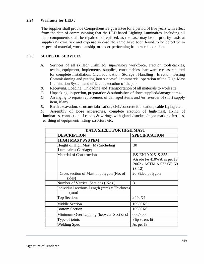
249
Signature of Tenderer
2.24 Warranty for LED :
The supplier shall provide Comprehensive guarantee for a period of five years with effect
from the date of commissioning that the LED based Lighting Luminaires, Including all
their components shall be repaired or replaced, as the case may be on priority basis at
suppliers’s own risk and expense in case the same have been found to be defective in
respect of material, workmanship, or under-performing from rated operation.
2.25 SCOPE OF SERVICES
A. Services of all skilled/ unskilled/ supervisory workforce, erection tools-tackles,
testing equipment, implements, supplies, consumables, hardware etc. as required
for complete Installation, Civil foundation, Storage , Handling , Erection, Testing
Commissioning and putting into successful commercial operation of the High Mast
Illumination System and efficient execution of the job.
B. Receiving, Loading, Unloading and Transportation of all materials to work site.
C. Unpacking, inspection, preparation & submission of short supplied/damage items.
D. Arranging to repair/ replacement of damaged items and /or re-order of short supply
item, if any.
E. Earth excavation, structure fabrication, civil/concrete foundation, cable laying etc.
F. Assembly of loose accessories, complete erection of high-mast, fixing of
luminaries, connection of cables & wirings with glands/ sockets/ tags/ marking ferrules,
earthing of equipment/ fitting/ structure etc.
DATA SHEET FOR HIGH MAST
SN DESCRIPTION SPECIFICATION
1 HIGH MAST SYSTEM
1.1 Height of High Mast (M) (including
Luminaires Carriage)
30
1.2 Material of Construction BS-EN10 025, S-355
/Grade Fe 410WA as per IS
2062 / ASTM A 572 GR 50
(S-12)
1.3 Cross section of Mast in polygon (No. of
sides)
20 Sided polygon
1.4 Number of Vertical Sections ( Nos.) 3
1.5 Individual sections Length (mm) x Thickness
(mm)
1.5.1 Top Sections 9440X4
1.5.2 Middle Section 10980X5
1.5.3 Bottom Section 10980X6
1.6 Minimum Over Lapping (between Sections) 600/800
1.7 Type of joints Slip stress fit
1.8 Welding Spec As per IS
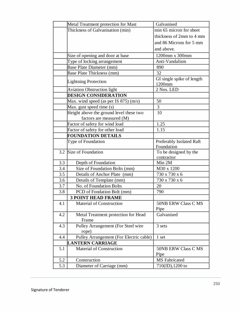
250
Signature of Tenderer
1.13 Metal Treatment protection for Mast Galvanised
1.14 Thickness of Galvanisation (min) min 65 micron for sheet
thickness of 2mm to 4 mm
and 86 Microns for 5 mm
and above.
1.15 Size of opening and door at base 1200mm x 300mm
1.16 Type of locking arrangement Anti-Vandalism
1.17 Base Plate Diameter (mm) 890
1.18 Base Plate Thickness (mm) 32
1.19 Lightning Protection GI single spike of length 1200mm
1.20 Aviation Obstruction light 2 Nos. LED
2 DESIGN CONSIDERATION
2.1 Max. wind speed (as per IS 875) (m/s) 50
2.2 Max. gust speed time (s) 3
2.3 Height above the ground level these two
factors are measured (M)
10
2.4 Factor of safety for wind load 1.25
2.5 Factor of safety for other load 1.15
3 FOUNFOUNDATION DETAILS
3.1 Type of Foundation Preferably Isolated Raft Foundation
3.2 Size of Foundation To be designed by the contractor
3.3 Depth of Foundation Min 2M
3.4 Size of Foundation Bolts (mm) M30 x 1200
3.5 Details of Anchor Plate (mm) 730 x 730 x 6
3.6 Details of Template (mm) 730 x 730 x 6
3.7 No. of Foundation Bolts 20
3.8 PCD of Fondation Bolt (mm) 790
4 3 POINT HEAD FRAME
4.1 Material of Construction 50NB ERW Class C MS
Pipe
4.2 Metal Treatment protection for Head
Frame
Galvanised
4.3 Pulley Arrangement (For Steel wire
rope)
3 sets
4.4 Pulley Arrangement (For Electric cable) 1 set
5 LANTERN CARRIAGE
5.1 Material of Construction 50NB ERW Class C MS
Pipe
5.2 Construction MS Fabricated
5.3 Diameter of Carriage (mm) 710(ID),1200 to
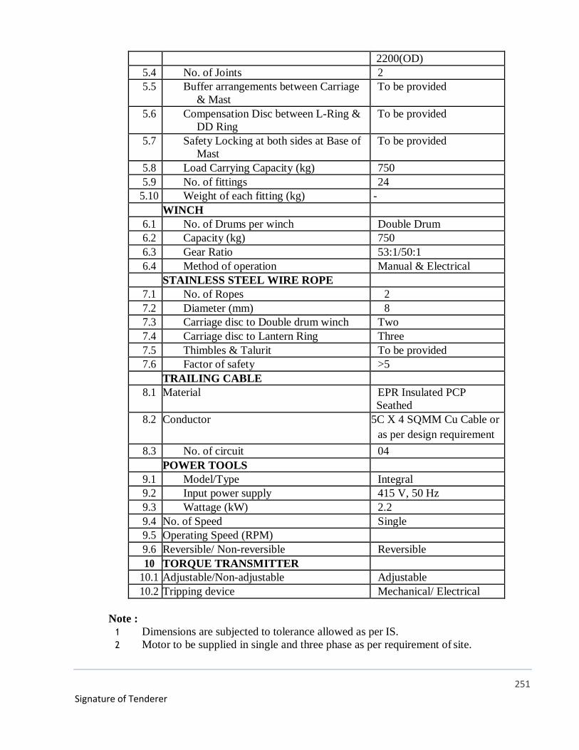
251
Signature of Tenderer
2200(OD)
5.4 No. of Joints 2
5.5 Buffer arrangements between Carriage
& Mast
To be provided
5.6 Compensation Disc between L-Ring &
DD Ring
To be provided
5.7 Safety Locking at both sides at Base of
Mast
To be provided
5.8 Load Carrying Capacity (kg) 750
5.9 No. of fittings 24
5.10 Weight of each fitting (kg) -
6 WINCH
6.1 No. of Drums per winch Double Drum
6.2 Capacity (kg) 750
6.3 Gear Ratio 53:1/50:1
6.4 Method of operation Manual & Electrical
7 STAINLESS STEEL WIRE ROPE
7.1 No. of Ropes 2
7.2 Diameter (mm) 8
7.3 Carriage disc to Double drum winch Two
7.4 Carriage disc to Lantern Ring Three
7.5 Thimbles & Talurit To be provided
7.6 Factor of safety >5
8 TRAILING CABLE
8.1 Material EPR Insulated PCP
Seathed
8.2 Conductor 5C X 4 SQMM Cu Cable or
as per design requirement
8.3 No. of circuit 04
9 POWER TOOLS
9.1 Model/Type Integral
9.2 Input power supply 415 V, 50 Hz
9.3 Wattage (kW) 2.2
9.4 No. of Speed Single
9.5 Operating Speed (RPM) 1440
9.6 Reversible/ Non-reversible Reversible
10 TORQUE TRANSMITTER
10.1 Adjustable/Non-adjustable Adjustable
10.2 Tripping device Mechanical/ Electrical
Note :
1 Dimensions are subjected to tolerance allowed as per IS.
2 Motor to be supplied in single and three phase as per requirement of site.
252
Signature of Tenderer
PART-II
CHAPTER - III
TECHNICAL SPECIFICATION OF DG SET, UNDERGROUND HSD TANK AND
PIPELINE
253
Signature of Tenderer
SPECIFICATION FOR DIESEL GENERATING SETS
1.0 GENERAL
This specification is intended to cover supply, installation, testing and commissioning of
500 KVA, 1010 KVA and 1500 KVA silent type, air-cooled (radiator type) Diesel Engine
Alternator Sets in outdoor type acoustic enclosure.
1.1 SCOPE OF WORK
The scope of work shall include under this specification design, manufacture, supply,
loading, unloading, storage, installation, testing and commissioning of the Diesel engine
alternator sets including labour, tools, tackles and plants, hardwares and consumables, steel
fabrication etc.
o Silent type Diesel engine alternator set complete with base frame & accessories and
with outdoor type acoustic enclosure.
o Fuel oil system including day service oil tank, piping, valves, filters etc. from engine to
service day oil tank. Return fuel line with fuel cooler and piping with accessories upto
day service tank etc.
o Lube oil system with piping etc.
o To design the mechanical ventilation system for D.G. enclosure with fans and duct etc.
as per system requirements.
o Suitable rating of 4 pole ACB with sheet-steel enclosure shall be mounted on D.G. set
suitable for cable connection from top/bottom.
o Exhaust emission shall meet latest CPCB & SPCB norms and residential silencer,
exhaust piping with mineral wool insulation and aluminium cladding as called for.
o Steel fabricated structure/support/hanger including fixing, grouting and bolting etc.
o Painting of steel work.
o Auxiliary control panel if required.
o All equipment shall be of the class most suitable for working under the conditions
specified and shall withstand the atmospheric conditions without deterioration.
o Minor civil work is included in the contractor’s scope of work. However, the
responsibility of coordination with the civil and other contracting agencies ensuring
completion of turnkey contract rests with the contractor.
o Contractor shall co-ordinate with all other agencies working at site for interconnection
and safety aspects.
o Also the D.G. supplier will furnish back up combined guarantee for 2 years from the
date of supply from Engine and alternator supplier for smooth running. In case there is

254
Signature of Tenderer
any defect the free replacement of any part or in whole will be made immediately at not
loss to Owner.
1.2 FEES & PERMITS
The contractor shall obtain all sanctions and permits required for the running of DG sets
from all the relevant authorities. All actual fee payable in this regard will be reimbursed
against receipt/documentary proof (evidence). On completion of the work, the supplier
shall obtain N.O.C from concerned authorities including Chief Electrical Inspectorate, of
State, and shall be delivered in original to the employer.
1.3 CODES & STANDARDS
The design, construction, manufacture, inspection, testing and performance shall comply
with all the currently applicable statutes, safety codes, relevant Bureau of Indian Standards
(BIS), British Standards (BS), International Electro Technical Commission (IEC)
publication, NEMA & VDE Standards amended upto date.
Some of the applicable standards are listed below:
IS – 1601 Performance and testing of IC engines for
general purpose.
BS– 649 : Performance and testing of IC engines for
general purpose.
BS – 4613 : Electrical performance of rotating electrical
machine.
[
BS – 4999/ 5000 : Applicable parts of BS 4999/5000.
IEC – 34-1/
IS – 4722/
VDE – 0530
: Specification for rotating electrical machines.
IS – 4889 : Method of determination of efficiency of
rotating electrical machinery.
IS – 6491 : Degrees of protection provided by enclosures for
rotating Electricity machinery.
IS – 4729 : Measurement and evaluation of vibration of
rotating Electrical machines.
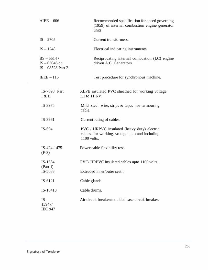
255
Signature of Tenderer
AIEE – 606 : Recommended specification for speed governing
(1959) of internal combustion engine generator
units.
IS – 2705 : Current transformers.
IS – 1248 : Electrical indicating instruments.
BS – 5514 /
IS – 03046 or
IS – 08528 Part 2
: Reciprocating internal combustion (I.C) engine
driven A.C. Generators.
IEEE – 115 : Test procedure for synchronous machine.
.
IS-7098 Part
I & II
: XLPE insulated PVC sheathed for working voltage
1.1 to 11 KV.
IS-3975 : Mild steel wire, strips & tapes for armouring
cable.
IS-3961 : Current rating of cables.
IS-694 : PVC / HRPVC insulated (heavy duty) electric
cables for working. voltage upto and including
1100 volts.
IS-424-1475
(F-3)
: Power cable flexibility test.
IS-1554
(Part-I)
: PVC/.HRPVC insulated cables upto 1100 volts.
IS-5083 : Extruded inner/outer seath.
IS-6121 : Cable glands.
IS-10418 : Cable drums.
IS-
13947/
IEC 947
: Air circuit breaker/moulded case circuit breaker.
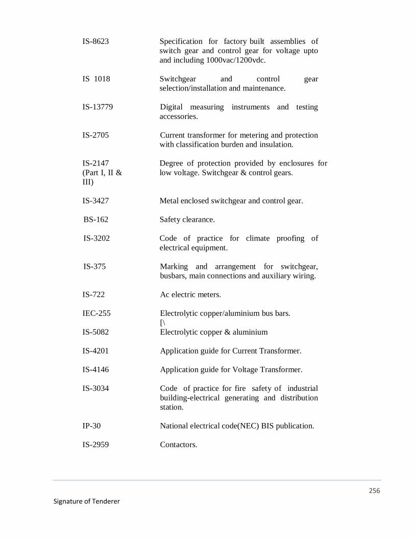
256
Signature of Tenderer
IS-8623 : Specification for factory built assemblies of
switch gear and control gear for voltage upto
and including 1000vac/1200vdc.
IS 1018 : Switchgear and control gear
selection/installation and maintenance.
IS-13779 : Digital measuring instruments and testing
accessories.
IS-2705 : Current transformer for metering and protection
with classification burden and insulation.
IS-2147
(Part I, II &
III)
: Degree of protection provided by enclosures for
low voltage. Switchgear & control gears.
IS-3427 : Metal enclosed switchgear and control gear.
BS-162 : Safety clearance.
IS-3202 : Code of practice for climate proofing of
electrical equipment.
IS-375 : Marking and arrangement for switchgear,
busbars, main connections and auxiliary wiring.
IS-722 : Ac electric meters.
IEC-255
: Electrolytic copper/aluminium bus bars.
[\
IS-5082 : Electrolytic copper & aluminium
IS-4201 : Application guide for Current Transformer.
IS-4146 : Application guide for Voltage Transformer.
IS-3034 : Code of practice for fire safety of industrial
building-electrical generating and distribution
station.
IP-30 : National electrical code(NEC) BIS publication.
IS-2959 : Contactors.
257
Signature of Tenderer
IS-1030-
1982
: Specification for carbon steel castings for
general engineering purpose
Indian Electricity Act.
Indian Electricity Rules.
Factory Act
1.4 DESIGN
The design and workmanship shall be in accordance with the best engineering practices, to
ensure satisfactory performance and service life. The equipments offered by the contractor
shall be complete in all respects. Any materials or accessories, which may not have been
specifically mentioned, but which are usual and necessary for the satisfactory and trouble
free operation and maintenance of the equipment shall be provided without any extra cost
to the purchaser. This shall also include & panes for commissioning of equipments.
All work to be performed and supplied shall be as a part of contract require specific
approval/review of Owner or his authorized representative. Major activities requiring
approval/review shall include but not to be limited to the following:
Bidder shall be responsible for:
Detailed co-ordination with other services, shop drawings for various electrical layouts
such as equipment layout, cabling layouts, earthing layouts, including equipment
installation and cable termination details etc. prior to start of work.
Preparation of bill of materials for cabling, earthing and miscellaneous items etc.
Cable schedule (as per site requirement).
Interconnection drawing.
Protection co-ordination drawings.
Shop inspection and testing procedures.
Field testing and commissioning procedures.
Preparation of as built drawings.
1.4.1 SITE CONDITIONS
1. Design ambient :- 50 Deg.C. maximum for engine and
40 deg C for alternator
2. Altitude :- 300M above sea level
3. Relative Humidity :- 98% maximum
4. Site environment :- Normal
1.4.2 DESIGN CRITERIA
ELECTRICAL DETAILS OF INCOMING SUPPLY
1. Supply Voltage 33 KV as per SEB approved.

258
Signature of Tenderer
2. Fault level (sym.) at supply of point
(designed)
1500 MVA (to be confirmed from
State Electricity Board by Tenderer).
3. Neutral : As per supply company
4. Voltage Variation : 5%
5. Frequency Variation : 3%
L.T. POWER DISTRIBUTION SYSTEM
1. Voltage 415 V
2. Frequency 50 Hz
3. Neutral Solidly Grounded
4. Short Circuit Fault withstand
Capacity
10 - 65 KA (1 Sec.)
CONTROL SUPPLY FOR ELECTRICAL SYSTEM
The various supply voltage to be used in the control panels for main equipments are:
1. Spring Charge Motor 230 Volt AC
2. Closing/Trip Coil 24 V DC
3. Alarm/Indication/Relay 24 V DC
4. Heaters 230 V AC
Painting of panel Powder coating of approved shade as per
Specification Clause of painting.
Painting of cable tray and structure steel
Powder coating of approved shade as per
Specification Clause of painting.
CABLE DETAILS
L.t. control cables
Copper conductor FRLS/PVC insulated
1.1 KV grade.
Power cables (l.t.)
Aluminum / copper conductor
FRLS/PVC / XLPE armored.
Grounding conductor
Copper/G.I. as per BOQ.
ACCURACY CLASS OF METERS

259
Signature of Tenderer
a) Revenue Meters Class 0.5 or as per SEB approved.
b) Ammeter Voltmeter and Other
Instrument
Digital Type.
1.4.3 DRAWINGS
i) The list of drawings along with this specifications is given. These drawings are
meant to give general idea to bidder regarding the nature of work covered by these
specifications.
ii) Any information/data shown/not shown in these drawings shall not relieve the
contractor of his responsibility to carry out the work as per the specifications.
Additional information required by the bidder for successfully completing the work
shall be obtained by him.
iii) Shop Drawings
The contractor shall prepare detailed coordinated electrical shop drawing. Cable
Schedule with other relevant services and submit to the Consultant for approval or
the Engineer-in-Charge before commencing the work. The shop drawings shall
indicate all setting out details and physical dimensions of all components with
wiring and cable details including system operating write up in the system i.e.
Control and Relay Panel D.G.’s, cable schedule and routes, manhole trap and fixing
details for the above mentioned work. All work shall be carried out on the approval
of these drawings. However, approval of these drawings do not relieve the contractor
of his responsibility for providing maintenance free and fool proof system including
any missing component/accessories to meet with the intent of the specifications.
Contractor will submit 2 prints for preliminary approval and finally six prints for
distribution.
iv) Completion Drawings/As Built Drawings
On completion of the work and before issue of certificate of virtual completion, the
contractor shall submit to the consultant 6 sets alongwith soft copy of ‘As Built’
drawings of the work alongwith originals including write up (trouble shooting,
installation, operation and maintenance manual with instructions) incorporating all
such changes and modifications during engineering and execution.
These drawings must provide:
Location of all earthing stations, route and size of all earthing conductors.
Layout and particulars of all cables.

260
Signature of Tenderer
Location and details of D.G. control panel/aux. panel, and relay panels with
description detailed control wiring diagram.
Layout of cable trays with support and their fixing details.
1.5 MANUFACTURER’S INSTRUCTIONS
Where manufacturers have furnished specific instructions, relating to the
material/equipments to be used on this job, covering points not specifically mentioned in
this documents, manufacturer’s instructions shall be followed.
1.6 MATERIALS AND EQUIPMENTS
All the materials and equipments shall be of the approved make and design. Unless
otherwise called for any approval by Owner’s Engineer-in-Charge, only the best quality
materials and equipment shall be used.
1.7 VENTILATION OPENING
In order to ensure adequate ventilation, compartments shall have ventilation openings
provided with fine wire mesh of brass to prevent the entry of insects and to reduce to a
minimum the entry of dirt and dust. Outdoor compartment openings shall be provided
with shutter type blinds.
1.8 DEGREE OF PROTECTION
The enclosures of the Control Cabinets, Junction Boxes and Marshalling Boxes, Panels
etc. to be installed shall provide degree of protection as detailed here under.
Installed out door :- IP-55.
Installed indoor in air-conditioned area: IP-31.
Installed in covered area :- IP-42.
Installed indoor in non air conditioned area where possibility of entry of water is
limited: IP-41.
For L.T. switchgear (AC and DC distribution boards) : IP-42.
The degree of protection shall be in accordance with IS:13947 (Part-I)/IEC-947 (Part-I).
Type test report for degree of protection test, on each type of the box shall be submitted for
approval.
1.9 RATING PLATES, NAME PLATES AND LABELS
D.G. Sets, D.G. control panel and auxiliaries items installed in the building is to
permanently attached to it in a conspicuous position. A rating plate of non-corrosive
material with engraved manufacturer’s name, year of manufacture, equipment name, type
or serial number together with details of the loading conditions of equipment in question
261
Signature of Tenderer
has been designed to operate and such diagram plates as may be required by the purchaser.
The rating plate of each equipment shall be according to IEC requirement.
All such nameplates, instruction plates, rating plates shall be bilingual with Hindi
inscription first followed by English. Alternatively two separate plates one with Hindi and
the other with English inscriptions may be provided.
1.10 FIRST FILL OF CONSUMABLES, OIL AND LUBRICANTS
All the first fill of consumables such as oils, lubricants, filling compounds, touch up paints,
welding/soldering/brazing material for all copper/G.I. earthing and essential chemicals etc,
(including diesel required for testing of DG). which will be required to put the
equipment/scheme covered under the scope of the specifications, into successful operation,
shall be furnished by the Contractor unless specifically excluded under the exclusions in
these specifications and documents.
1.11 DESIGN IMPROVEMENTS
The bidder shall note that the equipment offered by him in the bid only shall be accepted
for supply.
If for any reason, Contractor wishes to deviate from specification, prior permission from
Owner/Consultant shall be sought.
If any such change is agreed upon and that if affects the price and schedule of completion,
the parties shall agree in writing as to the extent of any change in the price and/or schedule
of completion before the Contractor proceeds with the change. Following such agreement,
the provision thereof, shall be deemed to have been amended accordingly in the
specification.
1.12 QUALITY ASSURANCE PROGRAMME
To ensure that the equipment and services under the scope of this Contract whether
manufactured or performed within the Contractor’s works or at his sub-contractor’s
premises or at the Purchaser’s site or at any other place of work are in accordance with the
specifications, the Contractor shall adopt suitable quality assurance programme to control
such activities at all points necessary. Such programme shall be outlined by the Contractor
and shall be finally accepted by the Purchaser after discussions. A quality assurance
programme of the contractor shall generally cover the following:
His organisation structure for the management and implementation of the proposed
quality assurance programme.
Documentation control system.
Qualification data for bidder’s key personnel.
262
Signature of Tenderer
The procedure for purchases of materials, parts components and selection of sub-
contractor’s services including vendor analysis, source inspection, incoming raw
material inspection, verification of material purchases etc.
System for shop manufacturing and site erection controls including process controls and
fabrication and assembly control.
Control of non-conforming items and system for corrective actions.
Inspection and test procedure both for manufacture and field activities.
Control of calibration and testing of measuring instruments and field activities.
System for indication and appraisal of inspection status.
System for quality audits.
System for authorising release of manufactured product to the Purchaser.
System for maintenance of records.
System for handling storage and delivery and
A quality plan detailing out the specific quality control measures and procedures
adopted for controlling the quality characteristics relevant to each item of equipment
furnished and/or services rendered.
The Purchaser or his duly authorised representative reserves the right to carry out quality
audit and quality surveillance of the system and procedure of the Contractor/his Vendor’s
quality management and control activities.
1.13 QUALITY ASSURANCE DOCUMENTS
The Contractor shall be required to submit the following Quality Assurance Documents
within three weeks after despatch of the equipment.
All Non-Destructive Examination procedures, stress relief and weld repair procedure
actually used during fabrication and reports including radiography interpretation reports.
Welder and welding operator qualification certificates.
Welder’s identification list, listing welder’s and welding operator’s qualification
procedure and welding identification symbols.
Raw material test reports on components as specified by the specification and/or agreed
to in the quality plan.
Stress relief time temperature charts/oil impregnation time temperature charts.
Factory test results for testing required as per applicable codes/mutually agreed quality
plan/standards referred in the technical specification.
The quality plan with verification of various customer inspection points (CIP) as
mutually and methods used to verify the inspection and testing points in the quality plan
were performed satisfactorily.
263
Signature of Tenderer
1.14 PACKAGING
All the equipments shall be suitably protected, coated, covered or boxed and crated to
prevent damage or deterioration during transit, handling and storage at Site till the time of
erection. While packing all the materials, the limitation from the point of view of
availability of Railway wagon/truck/trailer sizes in India should be taken account of the
Contractor shall be responsible for any loss or damage during transportation, handling and
storage due to improper packing. Any demurrage, wharfage and other such charges
claimed by the transporters, railways etc. shall be to the account of the Contractor. Owner
takes no responsibility of the availability of any special packaging/transporting
arrangement.
1.15 PROTECTION
All coated surfaces shall be protected against abrasion, impact, discolouration and any
other damages. All exposed threaded portions shall be suitably protected with either a
metallic or a non-metallic protecting device. All ends of all valves and pipings and
conduit equipment connections shall be properly sealed with suitable devices to protect
them from damage. The parts which are likely to get rusted, due to exposure to weather
should also be properly treated and protected in a suitable manner.
1.16 HANDLING, STORING AND INSTALLATION
In accordance with the specific installation instructions as shown on manufacturer’s
drawings or as directed by the Purchaser or his representative, the Contractor shall
unload, store, erect, install, wire, test and place into commercial use all the equipment
included in the contract. Equipment shall be installed in a neat, skillful manner so that it
is level, plumb, square and properly aligned and oriented.
Contractor shall follow the unloading and transporting procedure at site, as well as
storing, testing and commissioning of the various equipment being procured by him
separately. Contractor shall unload, transport, store, erect, test and commission the
equipment as per instructions of the manufacturer’s Engineer(s) and shall extend full co-
operation to them.
In case of any doubt/misunderstanding as to the correct interpretation of manufacturer’s
drawings or instructions, necessary clarifications shall be obtained form the
Owner/Consultant. Contractor shall be held responsible for any damage to the
equipment consequent for not following manufacturer’s drawings/instructions correctly.
Where assemblies are supplied in more than the one section, Contractor shall make all
necessary connections between sections. All components shall be protected against
damage during unloading, transportation, storage, installation, testing and
commissioning. Any equipment damaged due to negligence or carelessness or
otherwise shall be replaced by the Contractor at his own expense.
264
Signature of Tenderer
The Contractor shall submit to the Owner every week, a report detailing all the receipts
during the weeks. However, the Contractor shall be solely responsible for any shortages
or damages in transit, handling and/or in storage and erection of the equipment at Site.
Any demurrage, wharfage and other such charges claimed by the transporters, railways
etc. shall be to the account of the Contractor.
The Contractor shall be fully responsible for the equipment/material until the same is
handed over to the Owner in an operating condition after commissioning. Contractor
shall be responsible for the maintenance of the equipment/material while in storage as
well as after erection until taken over by Owner, as well as protection of the same
against theft, element of nature, corrosion, damages etc.
The Contractor shall be responsible for making suitable indoor storage facilities, to store
all equipment which require indoor storage.
The words ‘erection’ and ‘installation’ used in the specification are synonymous.
Exposed live parts shall be placed high enough above ground to meet the requirements
of electrical and other statutory safety codes.
The minimum phase to earth, phase to phase and section clearance along with other
technical parameters for the various voltage levels shall be maintained as per relevant
IS.
1.17 PROTECTIVE GUARDS
Suitable guards shall be provided for protection of personnel on all exposed rotating and/or
moving machine parts. All such guards with necessary spares and accessories shall be
designed for easy installation and removal for maintenance purpose.
1.18 DESIGN CO-ORDINATION
The Contractor shall be responsible for the selection and design of appropriate equipments
to provide the best co-ordinated performance of the entire system. The basic design
requirements are detailed out in this Specification. The design of various components,
sub-assemblies and assemblies shall be so done that it facilitate easy field assembly and
maintenance.
1.19 DESIGN CO-ORDINATION MEETING
The Contractor will be called upon to attend design co-ordination meetings with the
Engineer, and the Consultants of the Owner during the period of Contract. The Contractor
shall attend such meetings at his own cost at site/ office of Employer as and when required
and fully co-operate with such persons and agencies involved during those discussions.

265
Signature of Tenderer
1.20 DIESEL ENGINE
Air cooled, High speed diesel engine, electric starting, with integrated DG Set Controller
conforming to BS: 649/1958 with 10% over loading for one hour in any 12 hours duration.
The engine will be fitted with the following standard accessories. The supplier can quote
for equivalent engine and shall furnish complete details of the same along with tender
quotation.
a) Fly wheel to suite flexible coupling.
b) Flexible coupling.
c) Exhaust fan turbo charger with after cooler.
d) Cooling water centrifugal pump.
e) Radiator (engine mounted).
f) Corrosion resistor.
g) Automatic over speed trip protection.
h) Lub. oil pump.
i) Lub. oil priming pump (if Required).
j) Lub. oil filter.
k) By pass filter.
l) Fuel pump.
m) Fuel filter.
n) Air intake manifold.
o) PCC 3.3/EPC/wood ward/Powercom (having SEMs control system).
p) Self starter 24 volts DC including battery and battery charger.
q) Residential silencer.
r) Flexible pipe for silencers.
1.21 GOVERNING SYSTEM
The Governor shall be electronic fuel control type for coupled Genset.
1.22 EXHAUST SYSTEM
Engine emission exhaust system shall be meet the latest CPCB/SPCB norms of exhaust
emissions for D.G. Sets residential type silencer ducting, bends, hood/canopy, thermally
insulated aluminum clad exhaust piping etc. shall be provided along with structural support
with stays for each engine. Heat resistant paint shall be provided on exhaust pipe for the
portion which is of outside the building including canopy. Exhaust system pollution level
shall be indicated and shall be got approved by authorities. (Exhaust smoke quality &
quantity should be within the norms of central & state pollution control board).
266
Signature of Tenderer
1.23 EXHAUST PIPE INSULATION
Exhaust pipe insulation shall be carried out with mineral wool (rigid pipe sections) of 150
Kgs./Cu.m for temperature above 250 deg.C. The material for pipe insulation shall be
factory faced with aluminum foil reinforced with kraft paper. The aluminium foil of 24
SWG shall extend by minimum 50mm on one side of pipe side along the length to seal all
longitudinal joints etc.
1.24 ENGINE INDICATORS
a. Digital tachometer with running hour meter
b. Starting attempt counter
c. Lubricating oil pressure low
d. Water temp. High/low.
e. Water pressure low/high.
f. Over speed
g. Engine fail to start
h. KVA
i. Volts R-Y-B / RY-YB-BR.
j. Amps R-Y-B.
k. Fault condition with reset for engine.
1.25 ALTERNATOR (415V – 3 Phase, 4 Wire System)
The Alternator shall be industrial type screen protected drip proof. IP-23. Class – H
insulation with temperature rise limited to Class-’H’, self ventilated, air cooled, rotating
field, salient pole, brushless, machine with self excited, self regulated exciter and shall be
rated for continuous duty.
The Alternator shall have a continuous rating of not less than the value specified under
specific requirement.
The Alternator shall withstand without mechanical damage, an over load of 50% for a
period of 30 sec.
The generator/alternator shall with stand over load of 10% for 1 hour every 12 hourly. The
terminal voltage shall be adjustable and the range of adjustment shall be + 5% of nominal
voltage.
The Alternator shall be capable of withstanding without damage/injury for 3 secs., 3 phase
short circuit at its terminals, when operated at rated KVA and power factor at 5% over
voltage with fixed excitation (3 times the line current for 10 Sec.).
267
Signature of Tenderer
The Alternator shall be capable of withstanding for thirty (30) secs. a current of fifty (50)
percent in excess of its rated current, the voltage being maintained, as near the rated value
as possible, consistent with max. capacity of the prime mover.
All external nuts and bolts shall be of high tensile steel only.
The alternator shall be capable to sustain the unbalanced current between the phases
minimum 25% of rated current provide that the KVA rating and maximum current does
not exceed of rated current in any phase as per BS-4999 Part-101.
The alternator shall be dynamically balanced complete with rotor and shaft.
Damper winding shall be provided in the pole to damp the oscillations and ensure
satisfactory performance during parallel operation.
1.26 OUTDOOR TYPE ACOUSTIC ENCLOSURE FOR D.G. SET
a) Silent DG set container is of modular construction with the provision to assemble
and dismantle easily as per the site condition.
b) There are no protruding parts.
c) The container is fabricated out of CRCA sheet of 16 SWG.
d) The sheet metal components are hot dip nine tank pretreated.
e) To have long lift of container it is pure polyester based powder coated (inside as well
outside). All nut and bolts/hardware are zinc coated.
f) Fuel tank at the base of silent DG set is having required capacity. It is provided with
breather, drain plug.
g) The fuel level can be indicated with the help of fuel gauge meter.
h) There is provision for filling the fuel from outside as in the case of automobiles with
locking arrangement.
i) Battery is accommodated in a separate tray in the container.
j) There is a provision for drain plugs for draining mobile oil/diesel.
k) The doors are gasketed with high quality EPDN gaskets to avoid leakage of sound.
l) The door handles are lockable type.
m) Sound proofing of enclosure is done with high quality rock wool/mineral wool
confirming to IS:8183 of 50mm thickness and density at 96 Kgs/Cu.m.
n) The rock wool is further covered with fibre glass cloth and perforated powder coats
sheet.
o) A special residential silencer is provided with in the DG to control exhaust noise.
p) Specially designed attenuators are provided to control sound at air entry to the
container and exist from the container.
268
Signature of Tenderer
q) To make the system vibration free, engine and alternator (single bearing) is mounted
on anti-vibration pads.
r) Noise level is 75 dB(A) at 1 meter distance.
1.27 TESTS
The Diesel Generator sets shall be tested as per the relevant IEC Standards. All the tests
on individual and combined sets will be witnessed by the representative of employer with
no extra claim to employer. The supplier shall submit test reports complete
descriptions/testing procedure units accepted and value obtain from as per the following
but not limited to:
A. Acceptance Tests on D.G. Set.
One (1) hour at variable load including 10% overload at manufacturer works.
Before each test, the engine shall be brought to a steady state under the conditions of
the test.
B. Notice Period
Atleast 1 week notice time shall be maintained before the tests mentioned above by
manufacturer.
Test Certificate
a. Test Certificate shall be submitted in two (2) copies.
b. The test certificates shall be furnished to the purchaser for prior approval before
despatch of any equipment from works and the approval in writing from purchaser
shall be essential to effect despatch of the equipment.
c. The test reports shall furnish complete identification of the data including serial
number of each equipment.
1.28 COMMISSIONING :-
The commissioning of DG sets shall be done under the supervision of authorized
representative of OEM.
269
Signature of Tenderer
1.29 DEVIATION
Should the contractor desire to deviate from this specification in any way, he shall draw
specific attention to such deviation giving complete reasoning/comparison with other
products.
Unless such deviations are recorded in the separately attached Deviation Sheets, as
submitted with offer, it will be taken for granted that the offer is made in conformity with
this specification.
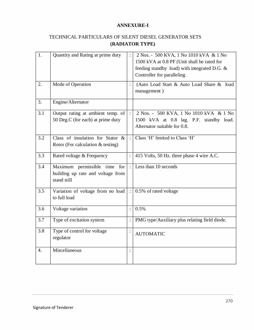
270
Signature of Tenderer
ANNEXURE-I
TECHNICAL PARTICULARS OF SILENT DIESEL GENERATOR SETS
(RADIATOR TYPE)
1. Quantity and Rating at prime duty : 2 Nos. - 500 KVA, 1 No 1010 kVA & 1 No
1500 kVA at 0.8 PF (Unit shall be rated for
feeding standby load) with integrated D.G. &
Controller for paralleling
2. Mode of Operation : (Auto Load Start & Auto Load Share & load
management )
3. Engine/Alternator
3.1 Output rating at ambient temp. of
50 Deg.C (for each) at prime duty
: 2 Nos. - 500 KVA, 1 No 1010 kVA & 1 No
1500 kVA at 0.8 lag. P.F. standby load.
Alternator suitable for 0.8.
3.2 Class of insulation for Stator &
Rotor (For calculation & testing)
: Class ‘H’ limited to Class ‘H’
3.3 Rated voltage & Frequency : 415 Volts, 50 Hz. three phase 4 wire A.C.
3.4 Maximum permissible time for
building up rate and voltage from
stand still
: Less than 10 seconds
3.5 Variation of voltage from no load
to full load
: 0.5% of rated voltage
3.6 Voltage variation : 0.5%
3.7 Type of excitation system : PMG type/Auxiliary plus relating field diode.
3.8 Type of control for voltage
regulator
: AUTOMATIC
4. Miscellaneous
:

271
Signature of Tenderer
4.1 Type of fuel for engine : High speed diesel in accordance with F-DMA or
F-DMS as per ISO 8217.
(IS : 1460 1974 amended upto date)
4.2 Day Oil tank capacity : 990 liters (outside) each for 1010/1500 KVA
D.G. Set. & 700 liters each for 500 KVA D.G
set
4.3 Maximum permissible starting time
for attaining full speed
: Within 15 seconds
4.4 Engine Starting : Electric starting system
4.5 Type of Governor
Electronic Fuel Control
: Electronic
4.6 Lubrication system : Pressure fed type.
4.7 Cooling System : Radiators
4. 8 Engine cranking system : To be included
4.9 Noise Level : 75 dbA at 1 mtr.
4.10 Vibration limit : Less than 250 micron
4.11 Main Switch : 2500A -4 pole ACB /800Amps 4 pole ACB
4.12 Acoustic Enclosure : Outdoor type
Technical literature, testing procedure with acceptable value shall be submitted along with the bid.
Any deviation (explained with supporting documents) shall also be submitted.
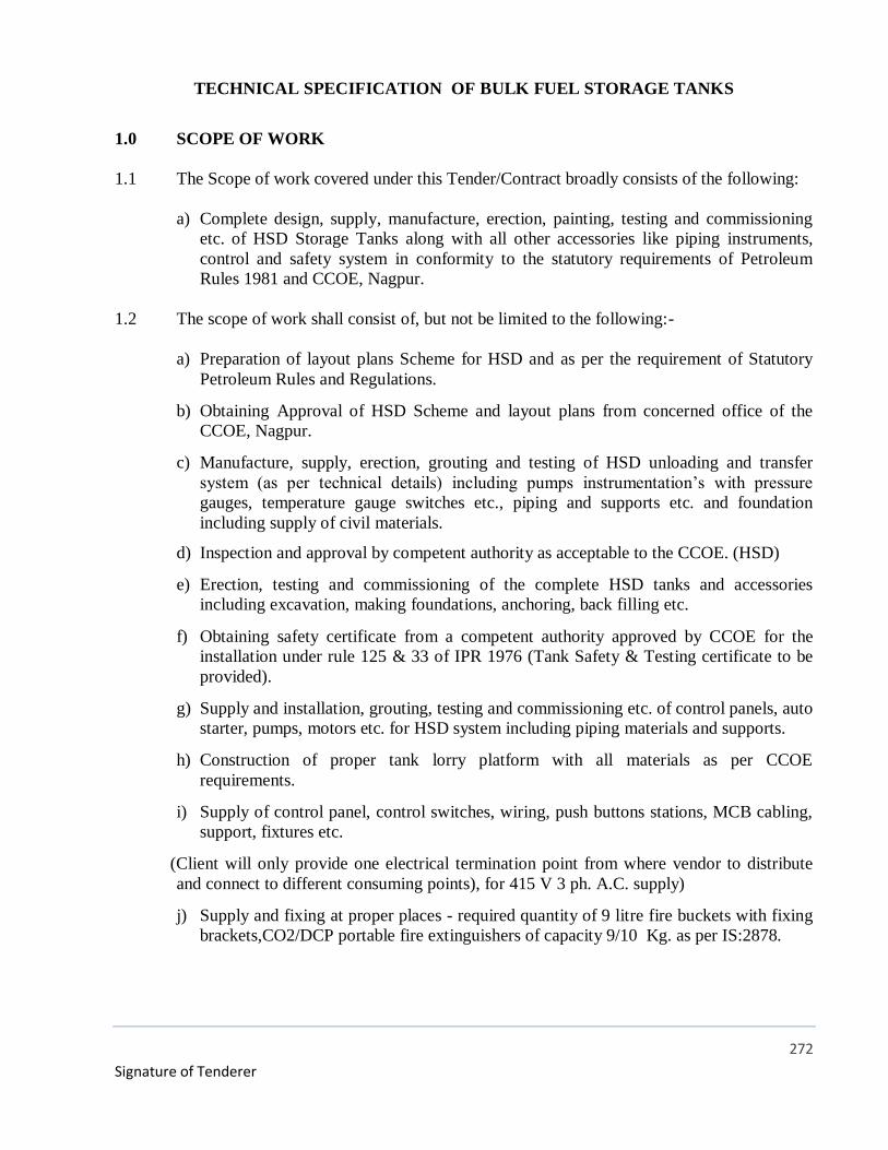
272
Signature of Tenderer
TECHNICAL SPECIFICATION OF BULK FUEL STORAGE TANKS
1.0 SCOPE OF WORK
1.1 The Scope of work covered under this Tender/Contract broadly consists of the following:
a) Complete design, supply, manufacture, erection, painting, testing and commissioning
etc. of HSD Storage Tanks along with all other accessories like piping instruments,
control and safety system in conformity to the statutory requirements of Petroleum
Rules 1981 and CCOE, Nagpur.
1.2 The scope of work shall consist of, but not be limited to the following:-
a) Preparation of layout plans Scheme for HSD and as per the requirement of Statutory
Petroleum Rules and Regulations.
b) Obtaining Approval of HSD Scheme and layout plans from concerned office of the
CCOE, Nagpur.
c) Manufacture, supply, erection, grouting and testing of HSD unloading and transfer
system (as per technical details) including pumps instrumentation’s with pressure
gauges, temperature gauge switches etc., piping and supports etc. and foundation
including supply of civil materials.
d) Inspection and approval by competent authority as acceptable to the CCOE. (HSD)
e) Erection, testing and commissioning of the complete HSD tanks and accessories
including excavation, making foundations, anchoring, back filling etc.
f) Obtaining safety certificate from a competent authority approved by CCOE for the
installation under rule 125 & 33 of IPR 1976 (Tank Safety & Testing certificate to be
provided).
g) Supply and installation, grouting, testing and commissioning etc. of control panels, auto
starter, pumps, motors etc. for HSD system including piping materials and supports.
h) Construction of proper tank lorry platform with all materials as per CCOE
requirements.
i) Supply of control panel, control switches, wiring, push buttons stations, MCB cabling,
support, fixtures etc.
(Client will only provide one electrical termination point from where vendor to distribute
and connect to different consuming points), for 415 V 3 ph. A.C. supply)
j) Supply and fixing at proper places - required quantity of 9 litre fire buckets with fixing
brackets,CO2/DCP portable fire extinguishers of capacity 9/10 Kg. as per IS:2878.
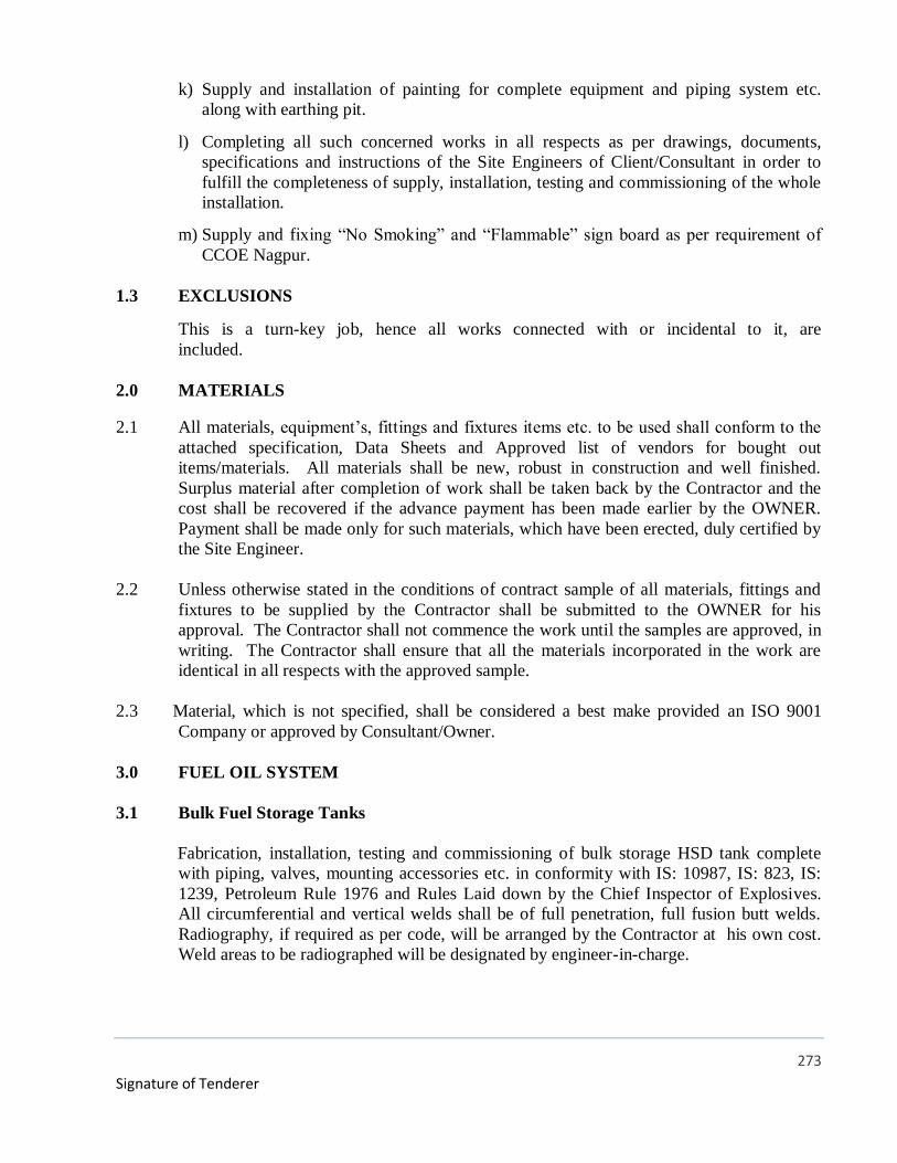
273
Signature of Tenderer
k) Supply and installation of painting for complete equipment and piping system etc.
along with earthing pit.
l) Completing all such concerned works in all respects as per drawings, documents,
specifications and instructions of the Site Engineers of Client/Consultant in order to
fulfill the completeness of supply, installation, testing and commissioning of the whole
installation.
m) Supply and fixing “No Smoking” and “Flammable” sign board as per requirement of
CCOE Nagpur.
1.3 EXCLUSIONS
This is a turn-key job, hence all works connected with or incidental to it, are
included.
2.0 MATERIALS
2.1 All materials, equipment’s, fittings and fixtures items etc. to be used shall conform to the
attached specification, Data Sheets and Approved list of vendors for bought out
items/materials. All materials shall be new, robust in construction and well finished.
Surplus material after completion of work shall be taken back by the Contractor and the
cost shall be recovered if the advance payment has been made earlier by the OWNER.
Payment shall be made only for such materials, which have been erected, duly certified by
the Site Engineer.
2.2 Unless otherwise stated in the conditions of contract sample of all materials, fittings and
fixtures to be supplied by the Contractor shall be submitted to the OWNER for his
approval. The Contractor shall not commence the work until the samples are approved, in
writing. The Contractor shall ensure that all the materials incorporated in the work are
identical in all respects with the approved sample.
2.3 Material, which is not specified, shall be considered a best make provided an ISO 9001
Company or approved by Consultant/Owner.
3.0 FUEL OIL SYSTEM
3.1 Bulk Fuel Storage Tanks
Fabrication, installation, testing and commissioning of bulk storage HSD tank complete
with piping, valves, mounting accessories etc. in conformity with IS: 10987, IS: 823, IS:
1239, Petroleum Rule 1976 and Rules Laid down by the Chief Inspector of Explosives.
All circumferential and vertical welds shall be of full penetration, full fusion butt welds.
Radiography, if required as per code, will be arranged by the Contractor at his own cost.
Weld areas to be radiographed will be designated by engineer-in-charge.

274
Signature of Tenderer
3.1.1 Construction
The Bulk Fuel Storage Tanks shall be suitable for storing HSD. The tanks shall confirm to
IS 10987 - 1992 and shall be suitable for underground installation. Tanks shall have
dished ends and shall be fabricated from 6 mm thick boiler quality plates conforming to IS
2002 - 1982. Tanks shall be designed for a pressure of 0.05 MPa when full of water.
Tanks shall be fabricated by welding. Welding procedure and qualification of welders shall
be as specified in IS 9595-1980 and IS 817-1966. Cylindrical shell be of full penetration
butt belt welded construction End plates shall be attached to the shell by double fillet
welds.
The Diesel storage tank shall be constructed of 6 mm thick mild steel sheets for cylinder
and 8 mm thick sheet for dished ends The tank shape shall be horizontal cylindrical. The
dish ends shall be made of 8 mm thick MS sheet. The tank shall be protected against
corrosion by way of anti corrosive coating or cathode protection as directed by the Chief
Controller of Explosives, Nagpur
All tanks shall be provided with vent pipes leading into the open air. The open end of the
vent pipe shall be covered with two layers of non-corrodible metal wire gauze of not less
than 11 meshes per centimeter and with a hood.
The tank shall be provided with an air space of not less than 5 % of the total capacity of
the tank.
The tanks shall be supported on well-designed saddle foundation. A bund wall shall be
constructed around the tank. The wall height shall be not less than 1200 mm height.
The tank height shall be such that the free flow by gravity shall be ensured to day tanks.
Tank Anchorage: Tanks to be installed underground shall be anchored to resist the
buoyancy force induced by high water tables that may occur seasonally. The anchorage
could be either provided by means of steel flats of round bars having adequate cross
section to resist the uplift at 29 stus level of 140 mp. The anchor should be embedded in
RCC draft having necessary dead weight bonding and shear strength to resist the up refer
force.
The construction of the tank shall be in conformity with relevant code of Practice and
bureau of Indian Standards.
3.1.2 Accessories
The tanks shall be provided with all standard accessories, nozzles and appurtenances as
indicated below.
a. Lifting lugs - 2 nos per tank
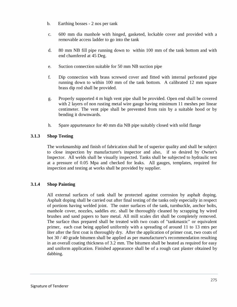
275
Signature of Tenderer
b. Earthing bosses - 2 nos per tank
c. 600 mm dia manhole with hinged, gasketed, lockable cover and provided with a
removable access ladder to go into the tank
d. 80 mm NB fill pipe running down to within 100 mm of the tank bottom and with
end chamfered at 45 Deg.
e. Suction connection suitable for 50 mm NB suction pipe
f. Dip connection with brass screwed cover and fitted with internal perforated pipe
running down to within 100 mm of the tank bottom. A calibrated 12 mm square
brass dip rod shall be provided.
g. Properly supported 4 m high vent pipe shall be provided. Open end shall be covered
with 2 layers of non rusting metal wire gauge having minimum 11 meshes per linear
centimeter. The vent pipe shall be prevented from rain by a suitable hood or by
bending it downwards.
h. Spare appurtenance for 40 mm dia NB pipe suitably closed with solid flange
3.1.3 Shop Testing
The workmanship and finish of fabrication shall be of superior quality and shall be subject
to close inspection by manufacturer's inspector and also, if so desired by Owner's
Inspector. All welds shall be visually inspected. Tanks shall be subjected to hydraulic test
at a pressure of 0.05 Mpa and checked for leaks. All gauges, templates, required for
inspection and testing at works shall be provided by supplier.
3.1.4 Shop Painting
All external surfaces of tank shall be protected against corrosion by asphalt doping.
Asphalt doping shall be carried out after final testing of the tanks only especially in respect
of portions having welded joint. The outer surfaces of the tank, turnbuckle, anchor bolts,
manhole cover, nozzles, saddles etc. shall be thoroughly cleaned by scrapping by wired
brushes and sand papers to bare metal. All mill scales dirt shall be completely removed.
The surface thus prepared shall be treated with two coats of "tankmastic" or equivalent
primer, each coat being applied uniformly with a spreading of around 11 to 13 mtrs per
liter after the first coat is thoroughly dry. After the application of primer coat, two coats of
hot 30 / 40 grade bitumen shall be applied as per manufacturer's recommendation resulting
in an overall coating thickness of 3.2 mm. The bitumen shall be heated as required for easy
and uniform application. Finished appearance shall be of a rough cast plaster obtained by
dabbing.
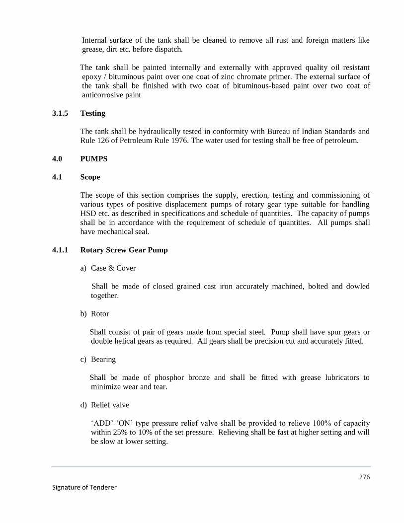
276
Signature of Tenderer
Internal surface of the tank shall be cleaned to remove all rust and foreign matters like
grease, dirt etc. before dispatch.
The tank shall be painted internally and externally with approved quality oil resistant
epoxy / bituminous paint over one coat of zinc chromate primer. The external surface of
the tank shall be finished with two coat of bituminous-based paint over two coat of
anticorrosive paint
3.1.5 Testing
The tank shall be hydraulically tested in conformity with Bureau of Indian Standards and
Rule 126 of Petroleum Rule 1976. The water used for testing shall be free of petroleum.
4.0 PUMPS
4.1 Scope
The scope of this section comprises the supply, erection, testing and commissioning of
various types of positive displacement pumps of rotary gear type suitable for handling
HSD etc. as described in specifications and schedule of quantities. The capacity of pumps
shall be in accordance with the requirement of schedule of quantities. All pumps shall
have mechanical seal.
4.1.1 Rotary Screw Gear Pump
a) Case & Cover
Shall be made of closed grained cast iron accurately machined, bolted and dowled
together.
b) Rotor
Shall consist of pair of gears made from special steel. Pump shall have spur gears or
double helical gears as required. All gears shall be precision cut and accurately fitted.
c) Bearing
Shall be made of phosphor bronze and shall be fitted with grease lubricators to
minimize wear and tear.
d) Relief valve
‘ADD’ ‘ON’ type pressure relief valve shall be provided to relieve 100% of capacity
within 25% to 10% of the set pressure. Relieving shall be fast at higher setting and will
be slow at lower setting.
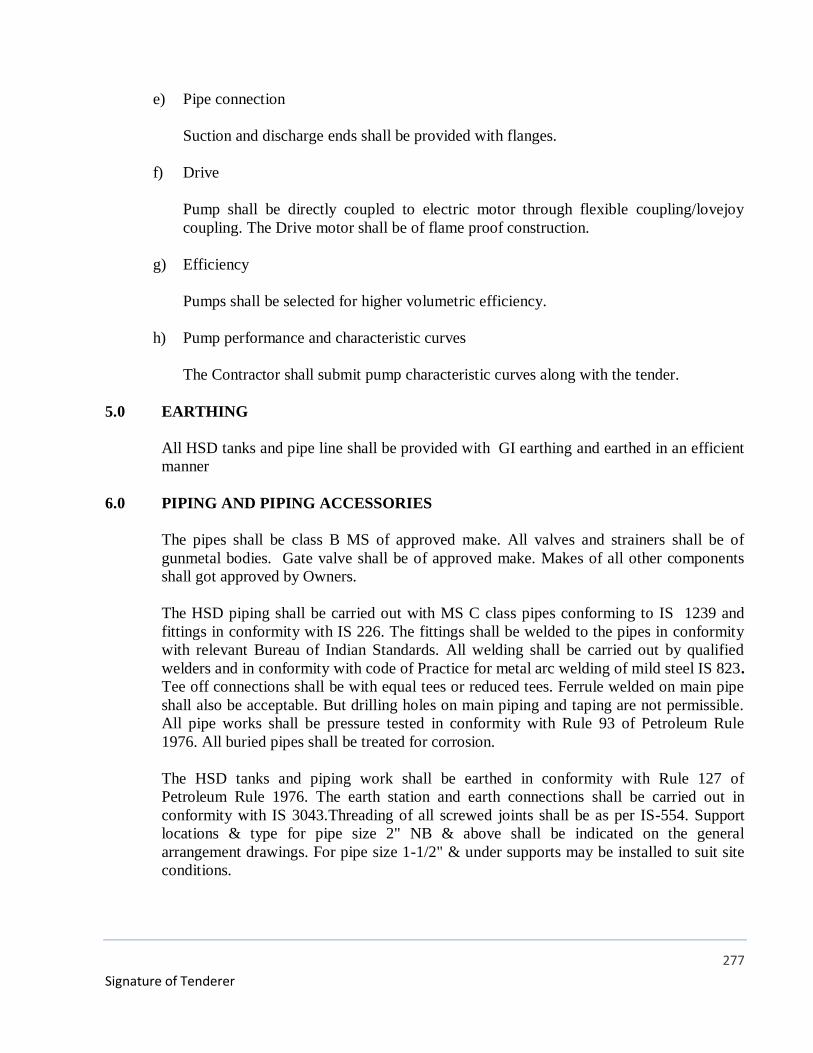
277
Signature of Tenderer
e) Pipe connection
Suction and discharge ends shall be provided with flanges.
f) Drive
Pump shall be directly coupled to electric motor through flexible coupling/lovejoy
coupling. The Drive motor shall be of flame proof construction.
g) Efficiency
Pumps shall be selected for higher volumetric efficiency.
h) Pump performance and characteristic curves
The Contractor shall submit pump characteristic curves along with the tender.
5.0 EARTHING
All HSD tanks and pipe line shall be provided with GI earthing and earthed in an efficient
manner
6.0 PIPING AND PIPING ACCESSORIES
The pipes shall be class B MS of approved make. All valves and strainers shall be of
gunmetal bodies. Gate valve shall be of approved make. Makes of all other components
shall got approved by Owners.
The HSD piping shall be carried out with MS C class pipes conforming to IS 1239 and
fittings in conformity with IS 226. The fittings shall be welded to the pipes in conformity
with relevant Bureau of Indian Standards. All welding shall be carried out by qualified
welders and in conformity with code of Practice for metal arc welding of mild steel IS 823.
Tee off connections shall be with equal tees or reduced tees. Ferrule welded on main pipe
shall also be acceptable. But drilling holes on main piping and taping are not permissible.
All pipe works shall be pressure tested in conformity with Rule 93 of Petroleum Rule
1976. All buried pipes shall be treated for corrosion.
The HSD tanks and piping work shall be earthed in conformity with Rule 127 of
Petroleum Rule 1976. The earth station and earth connections shall be carried out in
conformity with IS 3043.Threading of all screwed joints shall be as per IS-554. Support
locations & type for pipe size 2" NB & above shall be indicated on the general
arrangement drawings. For pipe size 1-1/2" & under supports may be installed to suit site
conditions.
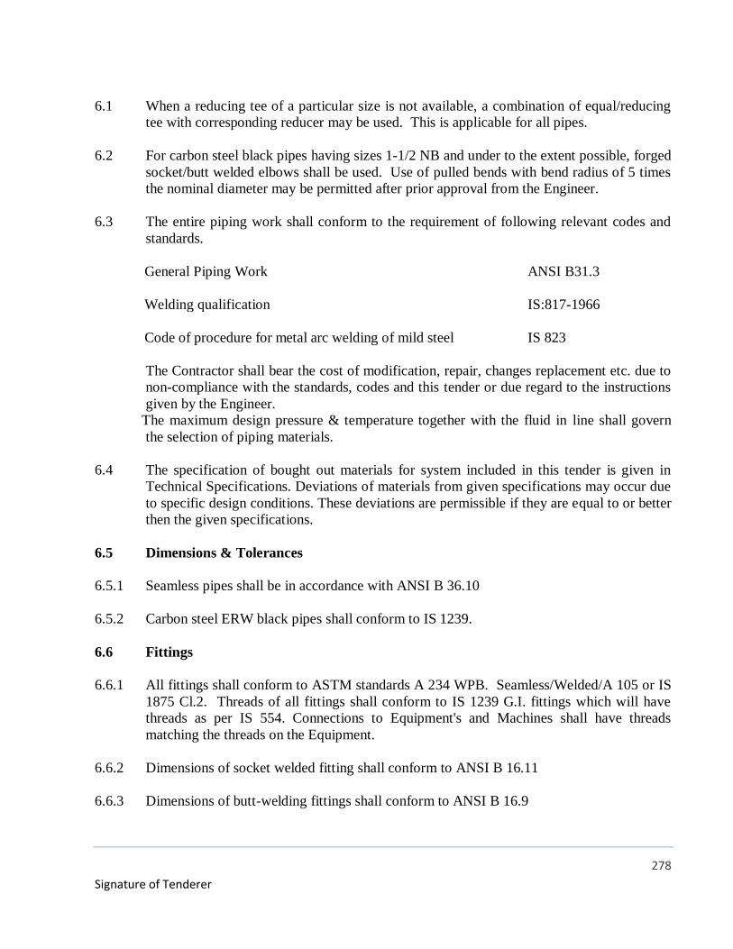
278
Signature of Tenderer
6.1 When a reducing tee of a particular size is not available, a combination of equal/reducing
tee with corresponding reducer may be used. This is applicable for all pipes.
6.2 For carbon steel black pipes having sizes 1-1/2 NB and under to the extent possible, forged
socket/butt welded elbows shall be used. Use of pulled bends with bend radius of 5 times
the nominal diameter may be permitted after prior approval from the Engineer.
6.3 The entire piping work shall conform to the requirement of following relevant codes and
standards.
General Piping Work ANSI B31.3
Welding qualification IS:817-1966
Code of procedure for metal arc welding of mild steel IS 823
The Contractor shall bear the cost of modification, repair, changes replacement etc. due to
non-compliance with the standards, codes and this tender or due regard to the instructions
given by the Engineer.
The maximum design pressure & temperature together with the fluid in line shall govern
the selection of piping materials.
6.4 The specification of bought out materials for system included in this tender is given in
Technical Specifications. Deviations of materials from given specifications may occur due
to specific design conditions. These deviations are permissible if they are equal to or better
then the given specifications.
6.5 Dimensions & Tolerances
6.5.1 Seamless pipes shall be in accordance with ANSI B 36.10
6.5.2 Carbon steel ERW black pipes shall conform to IS 1239.
6.6 Fittings
6.6.1 All fittings shall conform to ASTM standards A 234 WPB. Seamless/Welded/A 105 or IS
1875 Cl.2. Threads of all fittings shall conform to IS 1239 G.I. fittings which will have
threads as per IS 554. Connections to Equipment's and Machines shall have threads
matching the threads on the Equipment.
6.6.2 Dimensions of socket welded fitting shall conform to ANSI B 16.11
6.6.3 Dimensions of butt-welding fittings shall conform to ANSI B 16.9
279
Signature of Tenderer
6.6.4 Bore of socket welded fittings shall suit O.D of the corresponding pipe.
6.7 Bends, Mitres & Reducers Fabricated From Pipe
6.7.1 For pipe sizes 1-1/2" NB & under, cold pulled bends with a bend radius of 5 times the
nominal diameter of pipes may be used.
6.7.2 Pipe bends must be made true to angle & maximum reduction in diameter shall not exceed
3%.
6.7.3 While bending, the pipe shall be tampered and vibrated into place. After bending sand
shall be removed & bore of the pipe shall be thoroughly cleaned.
7.0 VALVES AND FITTINGS
Valves used in the work shall be ball type with bronze body. Pot strainers with cast iron
body and bronze mesh shall be used. The flow direction shall be shall be clearly marked on
the pipe and opening and closing direction on the valves. Non-return valves shall be
provided as required. Lift type non-return valves can be provided on horizontal runs of
pipes. Strainers shall be used in the piping system. The strainer shall be made of cast iron
body with GM or bronze mesh for the fine filtration. Cast iron valves, strainers etc. shall
not be used for HSD System.
7.1 Valves
7.1.1 Flange dimensions of carbon steel valves shall conform to ANSI B 16.5
7.1.2 Unless otherwise noted, valves shall conform to the following standards:
Gate valves 2"NB & above (other than C.I.) IS Standard
Gate valves 11/2"NB & under API/ASA Standard
Gate valves IS 780
Globe valves (all sizes) IS 10605
Check valves (other than C.I.) IS-10989/ASA Standard
Check valves IS 5312
Cast steel ball valves IS 1179/API Standard
6D/BS 5351
280
Signature of Tenderer
Flanges ASTM A105 or
IS 1875 Cl.2
IS 2062 Fabricated
C.S. butterfly valves IS 13095
7.1.3 Sizes & types not covered above shall conform to manufacturer standards & specifications
& the tendered shall furnish details of such valves along with the order.
7.2 Gaskets
7.2.1 Non metallic (CAF) gaskets shall conform to ANSI B 16.21
7.3 Bolts & Nuts
7.3.1 Bolting shall conform to IS 1367 unless specified otherwise.
7.4 Strainers
7.4.1 The strainers shall be bucket type of C.S. body with stainless steel internals, mesh size for
fine filtration of the oil.
7.5 Flanges
7.5.1 Dimensions of the flanges shall conform to ANSI B 16.5 Slip on flanges unless otherwise
specified.
7.5.2 Bore of weld neck flanges shall be to suit bore of the pipe. The thickness of neck shall be
to suit the thickness of pipe.
7.5.3 Threads for screwed flanges shall conform to IS-1239 standards except G.I. Flanges,
which shall have threads as per, IS 554.
8.0 PRE-FABRICATION
8.1 The Contractor shall fabricate all pipe work in conformity with the requirements of
approved drawings. Wherever specific details of fabrications are not indicated on the
drawings or not specified herein, the fabrication & erection work shall be done in
accordance with the code ANSI B 31.3.
8.2 The Contractor shall be responsible for working to the exact dimensions as per the
drawings subject to individual tolerances permissible, where errors or omissions are noted
in the drawings it shall be the responsibility of the Contractor to notify the Engineer prior
281
Signature of Tenderer
of fabrication and erection and Contractor shall, if necessary, carry out actual field
measurements.
9.0 ALIGNMENT
9.1 The pipes to be joined by welding shall be aligned correctly with the existing tolerances on
diameter, wall thickness and out of roundness. The same alignment shall be maintained
during the welding.
9.2 For internal misalignment due to difference in wall thickness of the matching components
exceeding 1/16", the component with higher wall thickness shall be internally
machined/ground, so that the adjoining surface are approximately flush. Dimensional
tolerance on fabrication shall be as under: -
i) Internal Misalignment : 1.0 mm (Max.)
ii) External Misalignment : 2.0 mm (Max.)
iii) Length : 0 to +3.0mm
iv) Inclination of flange face : +1/20 (but not to exceed
(i.e. angle between pipe 2mm at flange end)
axis & flange face)
v) Perpendicularity : 1 mm in 1000 mm
vi) Horizontally : 1 mm in 1000 mm
vii) Misalignment between pipe : + 1.6mm
Center and flange center
9.3 Other Alignment Considerations
9.3.1 The root opening for welded pipes shall not be more than 2.5 mm. A wire spacer of proper
diameter may be used for the weld root opening but must be removed after back welding
and before applying the root pass.
9.3.2 For pipes with wall thickness 5 mm and above the ends to be butt-welded shall be secured
with the aid of temporary weld attachments to maintain perfect alignment. These shall be
welded with electrodes suitable for welding the parent metal and shall be detached after
the completion of welding without causing any surface irregularities on the pipe. Tack
welds for only qualified welders shall do the alignment.
282
Signature of Tenderer
9.3.3 Flame cut bevel ends shall be thoroughly ground till the shining metal surface appears. The
V grooves thus prepared shall be tack welded with full penetration & shall become part of
finished weld.
9.3.4 Flange bolt holes shall straddle the normal centerlines unless different orientations are
shown in drawing to match equipment connections etc. For flanges in horizontal plane the
bolt holes shall straddle the north south axis unless specified otherwise.
9.3.5 No butt joints with a distance of 20 times the pipe diameter up-stream & 8 times the pipe
diameter downstream of orifice flange will be allowed in straight running pipes. The
flange weld inside the orifice flange shall be ground flush.
10.0 CLEANING OF PIPES & TANKS
10.1 All pipes and fittings shall be cleaned inside and outside by wire brush, cleaning tools,
compressed air etc. before fabrication and also after fabrication to ensure that the assembly
is free from all loose foreign materials such as seals, sand, weld spatter, particles, cutting
chips etc.
10.2 The area around the vessels shall be kept free from readily ignitable materials, such as
weeds and long dry grass by providing stone pitching.
10.3 On completion of erection and before hydraulic/ pneumatic testing all pipelines shall be
flushed with compressed air.
10.4 Cleaning requirements for special services if any shall be as specified by the Engineer.
11.0 WELDING
The welding procedure, types of electrodes etc. shall be in accordance with the following
IS specifications.
Welding procedure IS 823-1964
Welding Electrodes IS 814-1974
Testing of Welders IS 817-1966
11.1 Welding Procedure and Welder’s Qualification
11.1.1 The Contractor shall submit to the Engineer the welding procedure is intends to adopt for
approval. All the necessary arrangements for the procedure qualification shall be made by
the Contractor at his own cost. The Engineer or his representative shall witness the
welding procedure qualification test.
283
Signature of Tenderer
11.1.2 Only welders approved by the CCOE/Site Engineer and experienced and personnel site
staff shall be employed. The Contractor shall submit the welder qualification report before
the commencement of the work.
12.0 NO SMOKING
A permanent notice with letters minimum 10cm. High, prohibiting smoking and naked
lights shall be fixed to the fence surrounding the area.
13.0 AREA PROTECTION
The area where tanks, pumping equipment, loading and unloading facilities are located
shall be well protected by providing 2m high barbed wire fence of approved design and
requisite number of foam and chemical type fire extinguishers & sand backets as per the
requirements of Petroleum Rules and CCOE Nagpur.
14.0 ERECTION
14.1 For erection of piping, use of davite, welding of temporary supports on adjacent
equipment/structure, use of existing facilities etc. shall be allowed only after approval of
the Engineer.
14.2 All piping shall be routed and located as shown in “Approved for Construction” piping
drawings. However in order to suit site conditions, if pipelines are to be rerouted or
relocated, the same shall be carried out by the Contractor with the consent/approval of the
Engineer.
14.3 Location and design of pipe supports shown in the drawings shall be adhered to. However,
in order to suit site conditions, if the location of the pipe supports is required to be altered,
the same shall be carried out by the Contractor with the consent/approval of the Engineer.
14.4 The addition to the pipe supports indicated in the drawings, if required, the Contractor
shall have to provide additional supports to suit site conditions as desired/instructed by the
Engineer.
14.5 Slopes specified for various lines in the drawings or relevant IS standards and as directed
by the Engineer shall be maintained by the Contractor. In case the Contractor is unable to
maintain the desired slope, he shall check the sagging of the pipeline with a precision spirit
level.
14.6 In addition to the vents and drain shown in the drawing, the Contractor shall provide any
additional vents and drains as required for hydraulic tests and as desired by the Engineer.
284
Signature of Tenderer
15.0 ASSEMBLY
15.1 All flanges shall be so fitted that the gasket contact faces bear uniformly on the gasket, and
these made out with relatively uniform bolt stress.
15.2 All bolts shall extend completely through their nuts. Only bolts of adequate length required
diameter and material as per relevant standard should be used.
16.0 INSPECTION
16.1 Inspection of welds shall be carried out in accordance with applicable codes. All finish
welds shall be visually inspected for parallel and axial alignment of the work, excessive
reinforcement, concavity of welds shrinkage, cracks, inadequate penetration, undercuts and
other surface defects.
16.2 Wherever deemed necessary by the Engineer, the welded joints shall be examined for
defects with dye penetrant test.
16.3 Defects ascertained through the inspection methods that are not under permissible limits
shall be removed from the joint by the process of chipping or grinding. After re-weld the
joint shall be checked again.
16.4 When the entire joint is unacceptable the weld shall be cut completely and the pipe ends
shall be restored. After re-welding the joint shall be checked again.
17.0 TESTING
17.1 On completion of fabrication and/erection work, the Contractor shall inform Engineer in
writing, which after carrying out through inspection, instruct the Contractor to prepare for
pressure testing.
17.2 All equipment’s, materials consumables and services etc. mentioned below required for
carrying out pressure testing of piping shall be provided by the Vendor/Contractor at his
own cost.
Pump set for pressurization
Hoses for water, air or other test fluid with accessories and adopter flanges.
Supply, fabrication and erection of temporary piping with valves fittings.
Pressure gauges and all such instruments with necessary connections.
Temporary gaskets, supports, soap solution, grease, paints, tools and tackles etc.
285
Signature of Tenderer
17.3 Before testing all piping shall be cleaned and flushed with compressed air to make it free
from dirt, loose scale, debris and other loose foreign materials. The procedure for Air
flushing shall be as under:
The pipeline shall be pressurized by compressed air at the required pressure as directed by
the Engineer. Then the pressure will be released by quick opening of valve already in line
or installed temporarily for this purpose. This procedure will be repeated as many times as
required till inside of the pipe is fully cleaned. Piping shall not be flushed into vessels,
equipment’s etc. and care shall be taken during flushing so as not to damage/spoil other
agencies work.
17.4 With the exclusion of instrumentation, entire piping system shall be tested with water at
tanks 1.5 times the design pressure. (The design pressure shall be taken as 1.10 times the
operating pressure). The pressure shall be maintained for one hour.
17.5 In the event of failure of the system or any leakage noticed during testing, Contractor shall
speedily replace the defective portion/item and rectify the leakage. On completion of
rectification of system shall be again tested in accordance to above stipulations.
18.0 FLUSHING
After testing all pipelines shall be thoroughly flushed with dry compressed air.
19.0 CLEANING & PAINTING
19.1 On completion of all the above activities the outer surface of pipes fittings flanges etc. shall
be thoroughly cleaned with wire brush to remove any rust, scale oil grease etc., before
applying paint.
19.2 After cleaning to the entire satisfaction of the Engineer, the entire pipe line including fitting,
flanges, valves etc. shall be painted with two coats of protective primer and two coats of
final synthetic enamel paint of suitable colour code or specified by Consultant/Owner.
20.0 DRAWINGS
The drawings enclosed with the Tender are indicative type. For the piping installation work
the Contractor has to prepare shop installation drawings to suit the actual site conditions and
submit to Consultant/Client for approval. The final measurement of the work executed shall
be in accordance with these approved shop drawings and site measurements.
The drawings, specifications and bill of quantities shall be considered as a part of this
contract. Any work or materials shown on the drawings but not included in the Schedule of
Quantities or vice-versa shall be executed as if specifically called for in both without any
additional cost. The contract drawings indicate the extent and general arrangement of
various equipment’s and are essentially diagrammatic. The work shall be installed as
286
Signature of Tenderer
indicated on the drawings, however, any minor change if found essential to co-ordinate the
installation of this work with other trades shall be made without any additional cost to the
OWNER. The dimensions given herein and on the drawings are as could be secured, but its
complete accuracy is not guaranteed. The drawings and specifications are for the assistance
and guidance of the Contract, the exact locations, distances and levels will be governed by
the site conditions.
21.0 FIRE FIGHTING MEANS
Trolley type foam fire fighting equipment shall be provided in conformity with Petroleum
Rule 1976 with its up-to-date amendments. In addition to this, the fire extinguishers as
specified in the Scheme approval shall form part of the scope of work.
22.0 WATER SUPPLY & ELECTRICITY
The Contractors shall be responsible for all the arrangements needed to obtain supply of
water and electricity necessary for the works at his own cost. The Owner may agree to
provide water and electricity supply at one point as mutually agreed and the Contractor
subsequently shall arrange for further distribution for his requirements at his own cost.
Electricity shall be given by the Owner to Contractor on chargeable basis at the sole
discretion of the Owner.
23.0 ELECTRICAL WORKS
23.1 The electric work shall be carried out generally in accordance with the Indian Standard
Specifications with amendment upto-date while complying in all respects with the
requirements of the latest Indian Electricity Rules, Chapter IV of Petroleum Rule 1976.
23.2 The Electric work shall be carried out simultaneously with building work and will be
continued till it is completed satisfactorily along with the completion of essential portions
of building work.
23.3 If any minor alterations are found necessary, the Contractor will do the same within the
tendered rates.
23.4 The workmanship of the work should be free from defects and any defect in the work or
changes in the design etc., if pointed out shall be carried out by the Contractor within the
tendered rates.
23.5 The Contractor shall employ adequate labour to complete the work within the stipulated
time and make his own arrangements for housing labour and storage of materials etc. A
whole time Electrical Supervisor/Engineer shall be employed by the Contractor who will
remain at site of work to receive orders or any other instructions from the Engineer.
287
Signature of Tenderer
23.6 Any material supplied by the Client/Contractor/Vendor is damaged in any Way during
cartage or execution of work or otherwise shall be made good by the Contractor at his own
cost.
23.7 Completion Tests
On completion of electric installation the following tests shall be carried for:
a) Polarity test of switch
b) Earth resistance
23.8 Position of Switchers
a) The recommended position of the switchgear etc. as shown on the layout drawings
will be generally adhered to.
b) Should there by any discrepancy or incomplete description, ambiguity or omission in
the drawings and other documents whether original or supplementary, Contractor
shall immediately on discovering the same, draw attention of the Engineer.
c) Prior to the installation, the final position shall be ascertained by the Contractor with
the Engineer.
d) The dimensions and other details of the electrical drawings shall be compared with
the civil drawings at site before execution of the work.
23.9 Bus Bars
Bus bars shall be of aluminium and housed in separate bus bar chambers. Bus bars shall be
supported on unbreakable nonhygroscopic hylam supports rigidly held to the framework of
the chamber. The bus bar shall be suitably insulated. Bus bar chamber shall have a separate
screwed cover and the means shall be provided to identify the various phases of the bus
bars.
23.10 Cable Compartment
A cable compartment running along the vertical module shall be provided for easy
termination of all incoming and outgoing cable entering either from top or bottom.
Adequate supports shall be provided for the cables where necessary. The cable
compartment shall have its own screwed removable cover for easy access during cabling.
288
Signature of Tenderer
23.11 Cable Entry
Cubicles shall be designed to facilitate aluminium conductors PVC cable entry from top or
bottom as the case may be removable sheet steel plates shall be fitted at the top and bottom
to drill holes for cables entry at site.
24.0 INSPECTION AND APPROVAL BY OWNER
Soon after the work is completed, the Contractor shall inform the ‘Engineer’ in writing,
who after carrying out through inspection, instruct the Contractor to carry out mechanical
and other tests. The Contractor shall carry out all such tests to the entire satisfaction of the
Engineer and keep the system ready for commissioning.
25.0 TENDER RATES
All tender rates will include the cost of materials, erection, connections, labour,
supervision, tools, plant, transport, all taxes, contingencies, breakage, wastage, sundries,
scaffolding, maintenance or installation etc. till the completion of work. The rates include
cost of any work incidental to the items mentioned in the SOQ (See also para 1.3 of the
next chapter – HSD oil storage & distribution).
26.0 APPROVALS
The Contractor, while executing the work, shall conform to the provision of any
Government Act relating to the work and to the regulations and Bye laws of the local
authorities and of the company to whose system of supply and the installation is proposed
to be connected. The Contractor shall give all notices required by the Acts, Regulations or
Bylaws. He will also undertake to provide Test Certificate and drawings as required and
will make necessary arrangements to procure electricity supply without any extra charge.
The Contractor shall also obtain all approvals for the items of work done under this
contract from the appropriate authorities. All inspection fees or submission fees paid by
the Contractor will be reimbursed by the Owner against valid official receipts. Contractor
shall possess a valid electrical Contractor’s license issued by the Inspectorate of the Local
Government.

289
Signature of Tenderer
27.0 INSPECTION, APPROVAL AND OBTAINING LICENSE TO STORE HSD
The contractor shall prepare necessary shop drawings and documentation for the scheme
and submit the same to the Chief Inspectorate of Explosives Nagpur and liaise with them
for the preliminary and final inspection. Carry out necessary changes if any, and get the
system re-inspected and obtain Approval and License to store HSD by CCOE, Nagpur &
SICCL. The license shall be handed over to the client for their record.
Deposits if any shall be paid by the supplier and the same shall be reimbursed to them by
the client on production of original cash receipt.
28.0 SAMPLES
Samples of materials and fabrication drawings will be submitted by the Contractor
according to the schedule/ specification. Any deviation from the schedule/ specification
will have the written consent of the Engineer. However approval given by the Engineer
will not in any way exonerate the Contractor from his liability to carry out the work in
connection with the terms of contract.
29.0 COMMISSIONING OF THE SYSTEM
On completion of inspection and testing to the entire satisfaction of the Engineer, the
Engineer may instruct commissioning of each utility system with actual services to be
handles. The entire system shall be operated continuously for 72 hours and as directed by
the Engineer. Any defect noticed during the operation of the system is interrupted due to
any reasons, the Contractor shall speedily make necessary adjustments, modification to the
system etc. and again run the system continuously for 72 hours to the entire satisfaction of
the Engineer.
29.1 Completion Certificate
29.1.1 Application for Completion Certificate
When the Contractor fulfills his obligation for taking over, he shall be eligible to apply for
Completion Certificate. The Engineer shall normally issue to the Contractor the
Completion Certificate within one month after receiving an application from the
Contractor after verifying from completion documents and satisfying himself that the work
has been completed in accordance with and as set out in the construction and erection
drawings and the Contract Documents.
The Contractor after obtaining the Completion Certificate is eligible to present the final
bill for the work executed by him under the terms of contract.
290
Signature of Tenderer
29.1.2 Completion Certificate Documents
The following documents shall form the completion documents:
i) 6 Sets of the technical documents and descriptions according to which the work was
carried out.
ii) Six (6) sets of construction as-built drawings with 2 sets of reproduction drawings
showing therein the modification and corrections made during the course of
execution and signed by the Engineer.
iii) Certificate of tests performed for various works. Material and inspection test
certificates for supply items like pipes, fittings, valves etc.
iv) Material appropriation statement for the materials issued by the client for the works
and list of surplus materials returned to the client’s store duly supported by necessary
documents.
v) Manufacturer’s guarantee/warrantees for the equipment’s supplied, drawings etc. (4
copies).
30.0 STORAGE OF MATERIALS
30.1 The Contractor shall at his own expense provide suitable sheds and storage yards in such
places and in such numbers as in the opinion of the Engineer are needed for orderly and
proper storage of materials either supplied by the Company or as brought by the
Contractor for the Works. He shall obtain approval in writing from the Engineer for the
erection of such sheds and storage yards before undertaking construction thereof. Storage
and safe custody of materials shall be the responsibility of the Contractor.
31.0 WORK AND WORKMANSHIP
31.1 The work to be done under the Contract or that may be necessary to be done in order to
form and complete any part thereof shall be executed in the best and most substantial
workmanlike manner, with material of the best and most approved quality of their
respective kinds, and both the work and the materials should conform to the particulars
contained in or implied by the specifications and as referred to in and represented by the
drawings or in such other additional particulars, instructions and documents as may be
found requisite to be given during the execution of the works and to the entire satisfaction
of the Engineer according to the instructions and directions which the Contractor may from
time to time receive from the Engineer. The materials may be subjected to tests by means
of such machines, instruments and appliances as the Engineer may direct and such tests
shall be carried out by the Contractor wholly at his expenses. The work shall be executed
by good well-experienced and skilled staff. The Contractor if required shall produce
requisite evidence regarding qualification, experience data of his Engineer and other staff
291
Signature of Tenderer
etc. The Contractor welders shall be subject to welding qualification tests before Site
Engineer.
32.0 MEASUREMENT OF WORK
32.1 Payment will be made based on actual measurement of work completed as per BOQ; as per
relevant IS standard on linear measurement.
32.2 Measurement of pipelines shall be based on the execution drawings. Pipelines shall be
measured along with centre lines of pipes, curvilinear centre lines bends and elbows,
centre lines of flanges and other fittings, such as tees, bends, etc. All in lines instruments
and fittings (when paid for separately) shall be excluded from the measurement. Branch
connections shall be measured from the outer surface of the header.
32.3 Fabrication of spool pieces for temporary use to aid Contractor’s work such as fabrication.
Erection, flushing and testing piping shall be done by him, from the pipes and plates
procured by him, free of cost as part of piping work and no separate payment shall be
made for this.
33.0 GUARANTEE
33.1 The Contractor shall guarantee that all the materials, machinery and components, supplied,
fabricated, and installed by him shall be free from defects due to faulty supply of inferior
material and/or workmanship.
33.2 The period of guarantee shall be 12 months from the date the completion certificate is
issued, during which period any or all components found to be defective shall be replaced
or repaired free of charge and any short coming found in the system shall be removed at no
extra cost including supply the necessary personnel and tools for fulfilling the guarantee.
33.3 If the defects are not removed within a reasonable time, the client may arrange for
rectification at Contractor’s risk, and cost, without prejudice to any other rights.
34.0 DAMAGE TO OTHER WORKS
The Contractor shall take all possible care not to disturb the features of the building, as the
construction work is complete. Any damage i.e. breaking of walls, floor and damage to
painting surface etc. done by the supplier, the same shall be made good at his own cost and
risk.
35.0 AS FITTED DRAWING AND DOCUMENTATION
The Contractor shall prepare as fitted drawing and documentation and hand over 3 sets of
hard copy and one soft copy in CD for Client’s record.
292
Signature of Tenderer
PART - II
CHAPTER - IV
TECHNICAL SPECIFICATION OF CIVIL WORKS
293
Signature of Tenderer
GENERAL TECHNICAL SPECIFICATION
All works shall be executed as per latest CPWD’s specification as amended up to date, BIS Codes
amended up to date and other relevant codes as per directions of Engineer in charge.
In terms of work for which CPWD specifications are not available, execution of work shall be
carried out in accordance with standard practices and/or Manufacturer’s catalogue and as per
direction of Engineer in charge. Before execution of such items, Contractor has to submit his
methodology of execution & Manufacturer’s catalogues for approval to Engineer in charge.
Decision of Engineer in charge in this regard shall be final & binding on the contractor.
294
Signature of Tenderer
PART - II
CHAPTER - V
LIST OF APPROVED MAKES
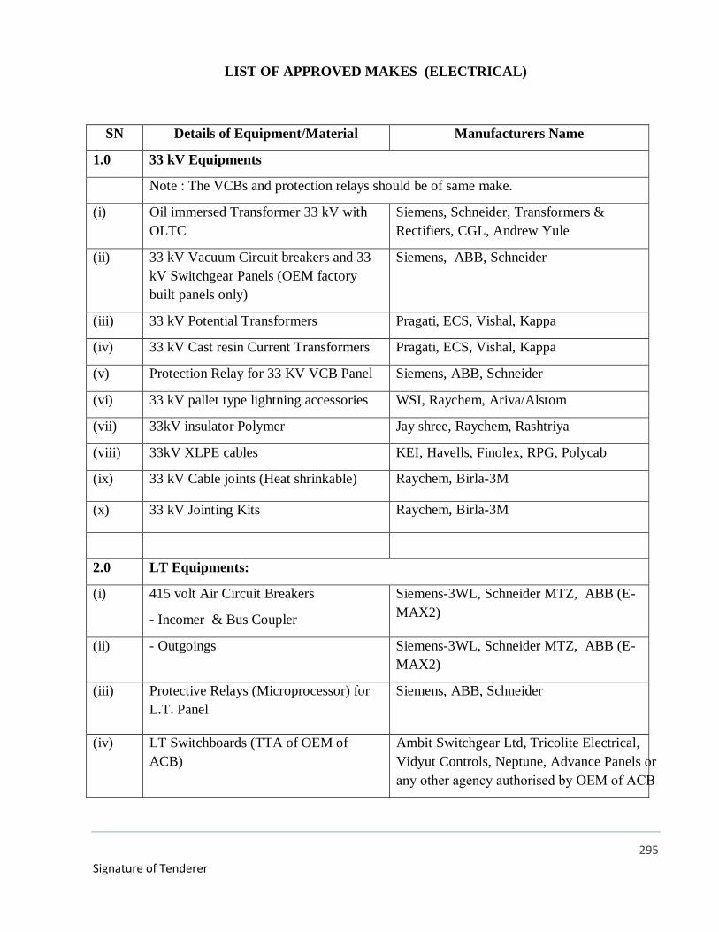
295
Signature of Tenderer
LIST OF APPROVED MAKES (ELECTRICAL)
SN Details of Equipment/Material Manufacturers Name
1.0 33 kV Equipments
Note : The VCBs and protection relays should be of same make.
(i) Oil immersed Transformer 33 kV with
OLTC
Siemens, Schneider, Transformers &
Rectifiers, CGL, Andrew Yule
(ii) 33 kV Vacuum Circuit breakers and 33
kV Switchgear Panels (OEM factory
built panels only)
Siemens, ABB, Schneider
(iii) 33 kV Potential Transformers Pragati, ECS, Vishal, Kappa
(iv) 33 kV Cast resin Current Transformers Pragati, ECS, Vishal, Kappa
(v) Protection Relay for 33 KV VCB Panel Siemens, ABB, Schneider
(vi) 33 kV pallet type lightning accessories WSI, Raychem, Ariva/Alstom
(vii) 33kV insulator Polymer Jay shree, Raychem, Rashtriya
(viii) 33kV XLPE cables KEI, Havells, Finolex, RPG, Polycab
(ix) 33 kV Cable joints (Heat shrinkable) Raychem, Birla-3M
(x) 33 kV Jointing Kits Raychem, Birla-3M
2.0 LT Equipments:
(i) 415 volt Air Circuit Breakers
- Incomer & Bus Coupler
Siemens-3WL, Schneider MTZ, ABB (E-
MAX2)
(ii) - Outgoings Siemens-3WL, Schneider MTZ, ABB (E-
MAX2)
(iii) Protective Relays (Microprocessor) for
L.T. Panel
Siemens, ABB, Schneider
(iv) LT Switchboards (TTA of OEM of
ACB)
Ambit Switchgear Ltd, Tricolite Electrical,
Vidyut Controls, Neptune, Advance Panels or any other agency authorised by OEM of ACB
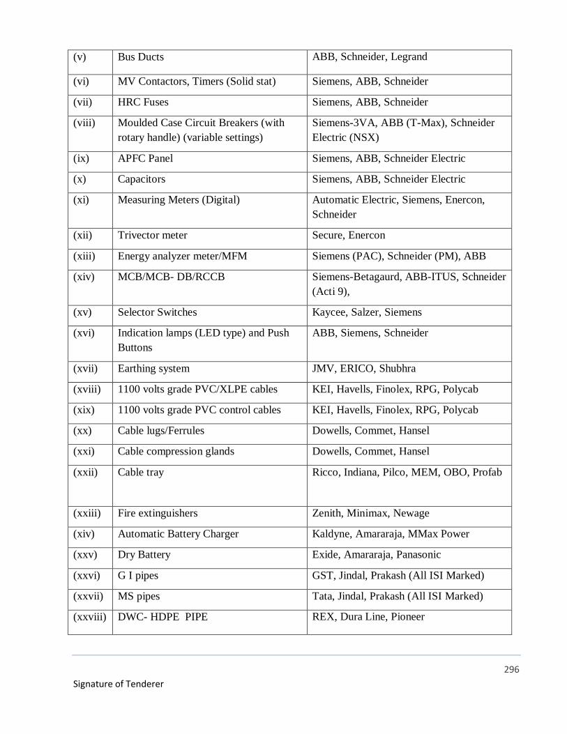
296
Signature of Tenderer
(v) Bus Ducts ABB, Schneider, Legrand
(vi) MV Contactors, Timers (Solid stat) Siemens, ABB, Schneider
(vii) HRC Fuses Siemens, ABB, Schneider
(viii) Moulded Case Circuit Breakers (with
rotary handle) (variable settings)
Siemens-3VA, ABB (T-Max), Schneider
Electric (NSX)
(ix) APFC Panel Siemens, ABB, Schneider Electric
(x) Capacitors Siemens, ABB, Schneider Electric
(xi) Measuring Meters (Digital) Automatic Electric, Siemens, Enercon,
Schneider
(xii) Trivector meter Secure, Enercon
(xiii) Energy analyzer meter/MFM Siemens (PAC), Schneider (PM), ABB
(xiv) MCB/MCB- DB/RCCB Siemens-Betagaurd, ABB-ITUS, Schneider
(Acti 9),
(xv) Selector Switches Kaycee, Salzer, Siemens
(xvi) Indication lamps (LED type) and Push
Buttons
ABB, Siemens, Schneider
(xvii) Earthing system JMV, ERICO, Shubhra
(xviii) 1100 volts grade PVC/XLPE cables KEI, Havells, Finolex, RPG, Polycab
(xix) 1100 volts grade PVC control cables KEI, Havells, Finolex, RPG, Polycab
(xx) Cable lugs/Ferrules Dowells, Commet, Hansel
(xxi) Cable compression glands Dowells, Commet, Hansel
(xxii) Cable tray Ricco, Indiana, Pilco, MEM, OBO, Profab
(xxiii) Fire extinguishers Zenith, Minimax, Newage
(xiv) Automatic Battery Charger Kaldyne, Amararaja, MMax Power
(xxv) Dry Battery Exide, Amararaja, Panasonic
(xxvi) G I pipes GST, Jindal, Prakash (All ISI Marked)
(xxvii) MS pipes Tata, Jindal, Prakash (All ISI Marked)
(xxviii) DWC- HDPE PIPE REX, Dura Line, Pioneer
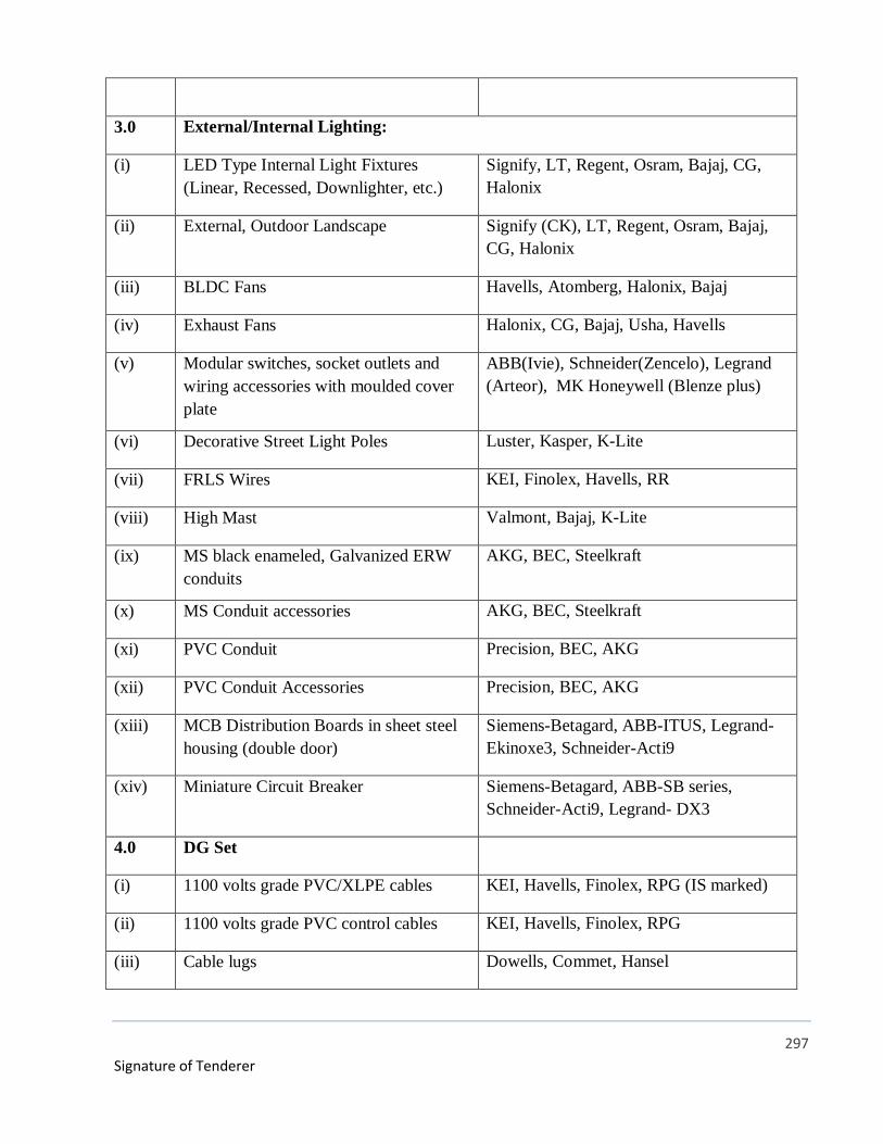
297
Signature of Tenderer
3.0 External/Internal Lighting:
(i) LED Type Internal Light Fixtures
(Linear, Recessed, Downlighter, etc.)
Signify, LT, Regent, Osram, Bajaj, CG,
Halonix
(ii) External, Outdoor Landscape Signify (CK), LT, Regent, Osram, Bajaj,
CG, Halonix
(iii) BLDC Fans Havells, Atomberg, Halonix, Bajaj
(iv) Exhaust Fans Halonix, CG, Bajaj, Usha, Havells
(v) Modular switches, socket outlets and
wiring accessories with moulded cover
plate
ABB(Ivie), Schneider(Zencelo), Legrand
(Arteor), MK Honeywell (Blenze plus)
(vi) Decorative Street Light Poles Luster, Kasper, K-Lite
(vii) FRLS Wires KEI, Finolex, Havells, RR
(viii) High Mast Valmont, Bajaj, K-Lite
(ix) MS black enameled, Galvanized ERW
conduits
AKG, BEC, Steelkraft
(x) MS Conduit accessories AKG, BEC, Steelkraft
(xi) PVC Conduit Precision, BEC, AKG
(xii) PVC Conduit Accessories Precision, BEC, AKG
(xiii) MCB Distribution Boards in sheet steel
housing (double door)
Siemens-Betagard, ABB-ITUS, Legrand-
Ekinoxe3, Schneider-Acti9
(xiv) Miniature Circuit Breaker Siemens-Betagard, ABB-SB series,
Schneider-Acti9, Legrand- DX3
4.0 DG Set
(i) 1100 volts grade PVC/XLPE cables KEI, Havells, Finolex, RPG (IS marked)
(ii) 1100 volts grade PVC control cables KEI, Havells, Finolex, RPG
(iii) Cable lugs Dowells, Commet, Hansel
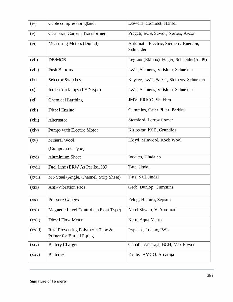
298
Signature of Tenderer
(iv) Cable compression glands Dowells, Commet, Hansel
(v) Cast resin Current Transformers Pragati, ECS, Savior, Nortex, Avcon
(vi) Measuring Meters (Digital) Automatic Electric, Siemens, Enercon,
Schneider
(vii) DB/MCB Legrand(Ekinox), Hager, Schneider(Acti9)
(viii) Push Buttons L&T, Siemens, Vaishno, Schneider
(ix) Selector Switches Kaycee, L&T, Salzer, Siemens, Schneider
(x) Indication lamps (LED type) L&T, Siemens, Vaishno, Schneider
(xi) Chemical Earthing JMV, ERICO, Shubhra
(xii) Diesel Engine Cummins, Cater Pillar, Perkins
(xiii) Alternator Stamford, Lerroy Somer
(xiv) Pumps with Electric Motor Kirloskar, KSB, Grundfos
(xv) Mineral Wool
(Compressed Type)
Lloyd, Minwool, Rock Wool
(xvi) Aluminium Sheet Indalco, Hindalco
(xvii) Fuel Line (ERW As Per Is:1239 Tata, Jindal
(xviii) MS Steel (Angle, Channel, Strip Sheet) Tata, Sail, Jindal
(xix) Anti-Vibration Pads Gerb, Dunlop, Cummins
(xx) Pressure Gauges Febig, H.Guru, Zepson
(xxi) Magnetic Level Controller (Float Type) Nand Shyam, V-Automat
(xxii) Diesel Flow Meter Kent, Aqua Metro
(xxiii) Rust Preventing Polymeric Tape &
Primer for Buried Piping
Pypecot, Loatax, IWL
(xiv) Battery Charger Chhabi, Amaraja, BCH, Max Power
(xxv) Batteries Exide, AMCO, Amaraja
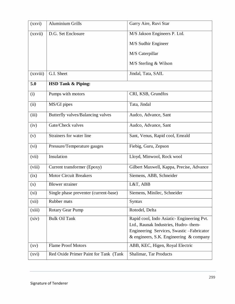
299
Signature of Tenderer
(xxvi) Aluminium Grills Garry Aire, Ruvi Star
(xxvii) D.G. Set Enclosure M/S Jakson Engineers P. Ltd.
M/S Sudhir Engineer
M/S Caterpillar
M/S Sterling & Wilson
(xxviii) G.I. Sheet Jindal, Tata, SAIL
5.0 HSD Tank & Piping:
(i) Pumps with motors CRI, KSB, Grundfos
(ii) MS/GI pipes Tata, Jindal
(iii) Butterfly valves/Balancing valves Audco, Advance, Sant
(iv) Gate/Check valves Audco, Advance, Sant
(v) Strainers for water line Sant, Venus, Rapid cool, Emrald
(vi) Pressure/Temperature gauges Fiebig, Guru, Zepson
(vii) Insulation Lloyd, Minwool, Rock wool
(viii) Current transformer (Epoxy) Gilbert Maxwell, Kappa, Precise, Advance
(ix) Motor Circuit Breakers Siemens, ABB, Schneider
(x) Blower strainer L&T, ABB
(xi) Single phase preventer (current-base) Siemens, Minilec, Schneider
(xii) Rubber mats Syntax
(xiii) Rotary Gear Pump Rotodel, Delta
(xiv) Bulk Oil Tank Rapid cool, Indo Asiatic- Engineering Pvt.
Ltd., Raunak Industries, Hudro- them-
Engineering Services, Swastic –Fabricator
& engineers, S.K. Engineering & company
(xv) Flame Proof Motors ABB, KEC, Higen, Royal Electric
(xvi) Red Oxide Primer Paint for Tank (Tank Shalimar, Tar Products
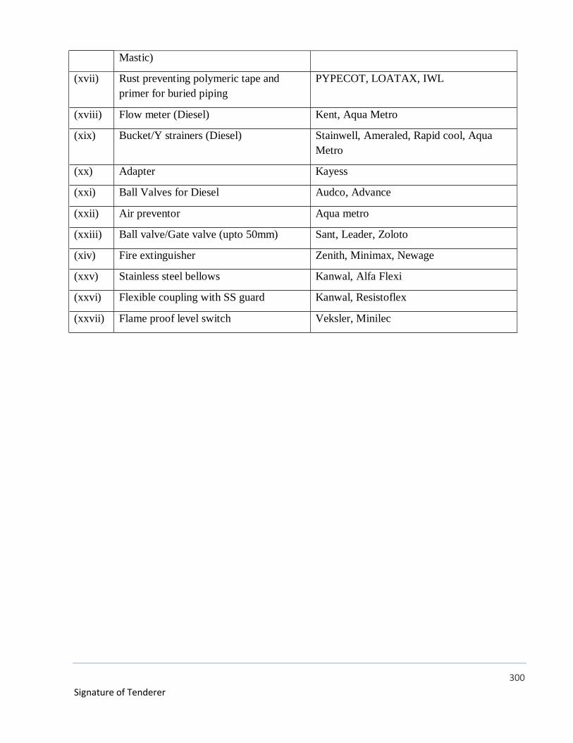
300
Signature of Tenderer
Mastic)
(xvii) Rust preventing polymeric tape and
primer for buried piping
PYPECOT, LOATAX, IWL
(xviii) Flow meter (Diesel) Kent, Aqua Metro
(xix) Bucket/Y strainers (Diesel) Stainwell, Ameraled, Rapid cool, Aqua
Metro
(xx) Adapter Kayess
(xxi) Ball Valves for Diesel Audco, Advance
(xxii) Air preventor Aqua metro
(xxiii) Ball valve/Gate valve (upto 50mm) Sant, Leader, Zoloto
(xiv) Fire extinguisher Zenith, Minimax, Newage
(xxv) Stainless steel bellows Kanwal, Alfa Flexi
(xxvi) Flexible coupling with SS guard Kanwal, Resistoflex
(xxvii) Flame proof level switch Veksler, Minilec
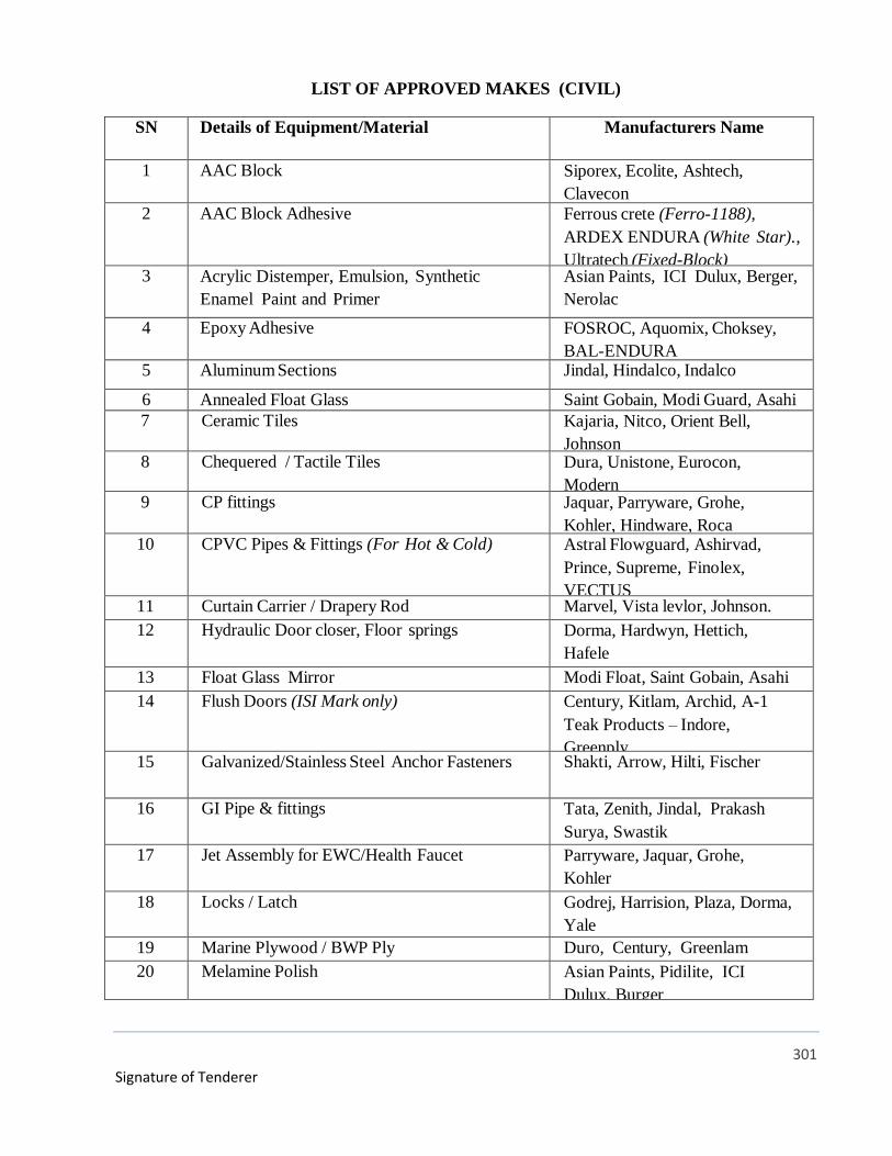
301
Signature of Tenderer
LIST OF APPROVED MAKES (CIVIL)
SN Details of Equipment/Material Manufacturers Name
1 AAC Block Siporex, Ecolite, Ashtech,
Clavecon
2 AAC Block Adhesive Ferrous crete (Ferro-1188),
ARDEX ENDURA (White Star).,
Ultratech (Fixed-Block)3 Acrylic Distemper, Emulsion, Synthetic
Enamel Paint and Primer
Asian Paints, ICI Dulux, Berger,
Nerolac
4 Epoxy Adhesive FOSROC, Aquomix, Choksey,
BAL-ENDURA 5 Aluminum Sections Jindal, Hindalco, Indalco
6 Annealed Float Glass Saint Gobain, Modi Guard, Asahi
7 Ceramic Tiles Kajaria, Nitco, Orient Bell,
Johnson 8 Chequered / Tactile Tiles Dura, Unistone, Eurocon,
Modern 9 CP fittings Jaquar, Parryware, Grohe,
Kohler, Hindware, Roca 10 CPVC Pipes & Fittings (For Hot & Cold) Astral Flowguard, Ashirvad,
Prince, Supreme, Finolex,
VECTUS11 Curtain Carrier / Drapery Rod Marvel, Vista levlor, Johnson.
12 Hydraulic Door closer, Floor springs Dorma, Hardwyn, Hettich,
Hafele
13 Float Glass Mirror Modi Float, Saint Gobain, Asahi
14 Flush Doors (ISI Mark only) Century, Kitlam, Archid, A-1
Teak Products – Indore,
Greenply15 Galvanized/Stainless Steel Anchor Fasteners Shakti, Arrow, Hilti, Fischer
16 GI Pipe & fittings Tata, Zenith, Jindal, Prakash
Surya, Swastik
17 Jet Assembly for EWC/Health Faucet Parryware, Jaquar, Grohe,
Kohler
18 Locks / Latch Godrej, Harrision, Plaza, Dorma,
Yale
19 Marine Plywood / BWP Ply Duro, Century, Greenlam
20 Melamine Polish Asian Paints, Pidilite, ICI
Dulux, Burger
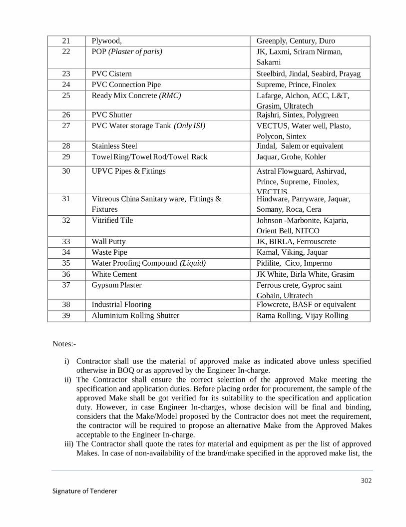
302
Signature of Tenderer
21 Plywood, Greenply, Century, Duro
22 POP (Plaster of paris) JK, Laxmi, Sriram Nirman,
Sakarni
23 PVC Cistern Steelbird, Jindal, Seabird, Prayag
24 PVC Connection Pipe Supreme, Prince, Finolex
25 Ready Mix Concrete (RMC) Lafarge, Alchon, ACC, L&T,
Grasim, Ultratech 26 PVC Shutter Rajshri, Sintex, Polygreen
27 PVC Water storage Tank (Only ISI) VECTUS, Water well, Plasto,
Polycon, Sintex
28 Stainless Steel Jindal, Salem or equivalent
29 Towel Ring/Towel Rod/Towel Rack Jaquar, Grohe, Kohler
30 UPVC Pipes & Fittings Astral Flowguard, Ashirvad,
Prince, Supreme, Finolex,
VECTUS31 Vitreous China Sanitary ware, Fittings &
Fixtures
Hindware, Parryware, Jaquar,
Somany, Roca, Cera
32 Vitrified Tile Johnson -Marbonite, Kajaria,
Orient Bell, NITCO
33 Wall Putty JK, BIRLA, Ferrouscrete
34 Waste Pipe Kamal, Viking, Jaquar
35 Water Proofing Compound (Liquid) Pidilite, Cico, Impermo
36 White Cement JK White, Birla White, Grasim
37 Gypsum Plaster Ferrous crete, Gyproc saint
Gobain, Ultratech 38 Industrial Flooring Flowcrete, BASF or equivalent
39 Aluminium Rolling Shutter Rama Rolling, Vijay Rolling
Notes:-
i) Contractor shall use the material of approved make as indicated above unless specified
otherwise in BOQ or as approved by the Engineer In-charge.
ii) The Contractor shall ensure the correct selection of the approved Make meeting the
specification and application duties. Before placing order for procurement, the sample of the
approved Make shall be got verified for its suitability to the specification and application
duty. However, in case Engineer In-charges, whose decision will be final and binding,
considers that the Make/Model proposed by the Contractor does not meet the requirement,
the contractor will be required to propose an alternative Make from the Approved Makes
acceptable to the Engineer In-charge.
iii) The Contractor shall quote the rates for material and equipment as per the list of approved
Makes. In case of non-availability of the brand/make specified in the approved make list, the

303
Signature of Tenderer
contractor can propose alternate equivalent make after ensuring that what he proposes
atleast meets both the quality and safety standard of the stipulated Makes and specifications
as stated in the Technical Specification. He shall also stand full guarantee to his alternate
proposal. The alternate Makes can be used only after an approval accorded by Engineer In-
charge, whose decision will be final in the matter.
iv) The contractor shall produce Manufacturer Test Certificates (MTC) and Warranty
Certificates/Invoices for material/equipment supplied for verification.
Signature of Tenderer
At the time of supply of item, the Contractor shall also furnish the OEM certificate for supplying maitenance spares, associated parts and any other support required for the period of codal life of the equipment.
v)


![[Automation, Electrification, and Shared Mobility in Freight]](https://static.fdokumen.com/doc/165x107/632813a2e491bcb36c0b98fc/automation-electrification-and-shared-mobility-in-freight.jpg)