MPI as a Programming Model for High-Performance Reconfigurable Computers
28
MPI as a Programming Model for High-Performance Reconfigurable Computers MANUEL SALDA ˜ NA, ARUN PATEL Arches Computing Systems CHRISTOPHER MADILL, DANIEL NUNES, DANYAO WANG, PAUL CHOW University of Toronto and RALPH WITTIG, HENRY STYLES, ANDREW PUTNAM Xilinx, San Jose High Performance Reconfigurable Computers (HPRCs) consist of one or more standard micro- processors tightly-coupled with one or more reconfigurable FPGAs. HPRCs have been shown to provide good speedups and good cost/performance ratios, but not necessarily ease of use, leading to a slow acceptance of this technology. HPRCs introduce new design challenges, such as the lack of portability across platforms, incompatibilities with legacy code, users reluctant to change their code base, a prolonged learning curve, and the need for a system-level Hardware/Software co-design development flow. This paper presents the evolution and current work on TMD-MPI, which started as an MPI-based programming model for Multiprocessor Systems-on-Chip imple- mented in FPGAs, and has now evolved to include multiple X86 processors. TMD-MPI is shown to address current design challenges in HPRC usage, suggesting that the MPI standard has enough syntax and semantics to program these new types of parallel architectures. Also presented is the TMD-MPI Ecosystem, which consists of research projects and tools that are developed around TMD-MPI to further improve HPRC usability. Finally, we present preliminary communication performance measurements. Categories and Subject Descriptors: C.1.3 [Computer Systems Organization]: Processor Architectures—Adaptable architectures; C.0 [Computer Systems Organization]: General— Hardware/software interfaces; D.1.3 [Software]: Programming Techniques—Parallel Program- ming General Terms: Design, Experimentation, Performance, Standardization Additional Key Words and Phrases: MPI, FPGA, Parallel Programming, Co-design, Programming Model, Reconfigurable, High-Performance We acknowledge the CMC/SOCRN, NSERC and Xilinx for the hardware, tools and funding provided for this project. Thanks to Vincent Mirian for his collaboration and feedback. Author’s address: Manuel Salda˜ na, Arun Patel, Arches Computing Systems, Toronto, Canada, email: {ms,ap}@archescomputing.com; Christopher Madill, Daniel Nunes, Danyao Wang, Paul Chow, University of Toronto, Toronto, Canada, email: {cmadill,dnunes,wangda,pc}@eecg.toronto.edu; Ralph Wittig, Henry Styles, Andrew Put- nam, Xilinx, San Jose, USA, emails: {wittig,henrys,andrewrp}@xilinx.com Permission to make digital/hard copy of all or part of this material without fee for personal or classroom use provided that the copies are not made or distributed for profit or commercial advantage, the ACM copyright/server notice, the title of the publication, and its date appear, and notice is given that copying is by permission of the ACM, Inc. To copy otherwise, to republish, to post on servers, or to redistribute to lists requires prior specific permission and/or a fee. c 20YY ACM 0000-0000/20YY/0000-0001 $5.00 ACM Journal Name, Vol. V, No. N, Month 20YY, Pages 1–28.
-
Upload
independent -
Category
Documents
-
view
2 -
download
0
Transcript of MPI as a Programming Model for High-Performance Reconfigurable Computers
MPI as a Programming Model forHigh-Performance Reconfigurable Computers
MANUEL SALDANA, ARUN PATEL
Arches Computing Systems
CHRISTOPHER MADILL, DANIEL NUNES, DANYAO WANG, PAUL CHOW
University of Toronto
and
RALPH WITTIG, HENRY STYLES, ANDREW PUTNAM
Xilinx, San Jose
High Performance Reconfigurable Computers (HPRCs) consist of one or more standard micro-processors tightly-coupled with one or more reconfigurable FPGAs. HPRCs have been shown toprovide good speedups and good cost/performance ratios, but not necessarily ease of use, leadingto a slow acceptance of this technology. HPRCs introduce new design challenges, such as thelack of portability across platforms, incompatibilities with legacy code, users reluctant to changetheir code base, a prolonged learning curve, and the need for a system-level Hardware/Softwareco-design development flow. This paper presents the evolution and current work on TMD-MPI,which started as an MPI-based programming model for Multiprocessor Systems-on-Chip imple-mented in FPGAs, and has now evolved to include multiple X86 processors. TMD-MPI is shownto address current design challenges in HPRC usage, suggesting that the MPI standard has enoughsyntax and semantics to program these new types of parallel architectures. Also presented is theTMD-MPI Ecosystem, which consists of research projects and tools that are developed aroundTMD-MPI to further improve HPRC usability. Finally, we present preliminary communicationperformance measurements.
Categories and Subject Descriptors: C.1.3 [Computer Systems Organization]: ProcessorArchitectures—Adaptable architectures; C.0 [Computer Systems Organization]: General—Hardware/software interfaces; D.1.3 [Software]: Programming Techniques—Parallel Program-ming
General Terms: Design, Experimentation, Performance, Standardization
Additional Key Words and Phrases: MPI, FPGA, Parallel Programming, Co-design, ProgrammingModel, Reconfigurable, High-Performance
We acknowledge the CMC/SOCRN, NSERC and Xilinx for the hardware, tools and fundingprovided for this project. Thanks to Vincent Mirian for his collaboration and feedback.Author’s address: Manuel Saldana, Arun Patel, Arches Computing Systems,Toronto, Canada, email: {ms,ap}@archescomputing.com; Christopher Madill, DanielNunes, Danyao Wang, Paul Chow, University of Toronto, Toronto, Canada, email:{cmadill,dnunes,wangda,pc}@eecg.toronto.edu; Ralph Wittig, Henry Styles, Andrew Put-nam, Xilinx, San Jose, USA, emails: {wittig,henrys,andrewrp}@xilinx.com
Permission to make digital/hard copy of all or part of this material without fee for personalor classroom use provided that the copies are not made or distributed for profit or commercialadvantage, the ACM copyright/server notice, the title of the publication, and its date appear, andnotice is given that copying is by permission of the ACM, Inc. To copy otherwise, to republish,to post on servers, or to redistribute to lists requires prior specific permission and/or a fee.c© 20YY ACM 0000-0000/20YY/0000-0001 $5.00
ACM Journal Name, Vol. V, No. N, Month 20YY, Pages 1–28.

2 · Manuel Saldana et al.
1. INTRODUCTION
Portability in a typical High-Performance Computer (HPC) is achieved by usingstandards-based operating systems and software layers (Middleware) that abstractmachine-specific hardware from the software application, as shown in Figure 1on the left. The UNIX operating system (and its variants) and the MPI [TheMPI Forum 1993] library are examples of de-facto standards that enabled portableparallel applications across HPCs. For HPRC designs to be truly portable, theseconcepts must be extended to the FPGAs, as they are now part of the application.Figure 1 shows how portability for HPRCs must come from two sides: applicationsoftware and application hardware.
For HPRC’s, the hardware operating system and hardware middleware shouldprovide a standard abstraction for application hardware engines to access host-specific resources, such as external memory and communications. Examples of thesehost-specific communication resources are the X86-FPGA communication mediums,such as Intel’s Front Side Bus (FSB) or QuickPath [Intel 2009a], AMD’s Hyper-Transport [HyperTransport Consortium 2009], Cray’s Rapid Array Transport [CrayInc. 2005], SGI’s Scalable System Port–NUMA link connection [SGI 2008], or evenPCI Express. Companies such as Cray [CRAY, Inc. 2009], SGI [SGI 2009], In-tel [Intel, Corp. 2009], Nallatech [Nallatech, Inc. 2009], XtremeData [Xtreme DataInc. 2009], DRC [DRC computer 2009] and SRC [SRC Computers, Inc. 2009]provide their own low-level software APIs and their own hardware interfaces forapplication hardware engines. HPRCs are now in a similar stage as HPCs werebefore the appearance of MPI [The MPI Forum 1993] when every vendor had theirown message-passing API to program their own supercomputers causing a lack ofportable designs. Currently, there is no implemented standard API for a high-levelparallel programming model that includes the interaction between X86 processorsand FPGAs. There is, however, interesting progress done by the OpenFPGA [2009]organization on this matter, which is compared against this work in Section 5.
SW Application
SW Middleware
SW OS
HW Application
HW Middleware
HW OS
OS
Application
Middleware
Host-specific
Hardware
Host-specific
Hardware
X86s
FPGAs
Typical HPCs For HPRCs
Fig. 1. Comparison between HPC and HPRC abstraction layers
Previous work proposed TMD-MPI [Saldana 2006; Saldana and Chow 2006;Saldana et al. 2006; Patel et al. 2006] as a subset implementation of the MPIstandard targeting Multiprocessor System-on-Chip implementations across multi-ple FPGAs to abstract hardware details from the user as well as to provide awell-known, high-level parallel programming API. In three years, TMD-MPI hasACM Journal Name, Vol. V, No. N, Month 20YY.
MPI as a Programming Model for High-Performance Reconfigurable Computers · 3
evolved in a bottom-up approach to the point where it provides software and hard-ware middleware layers of abstraction for communications to enable the portableinteraction between embedded processors, specialized hardware computing enginesand now X86 processors; all programmed under the same message passing paradigmmaking it a unified programming model for HPRCs.
This paper provides a summary of TMD-MPI’s philosophy and evolution, fol-lowed by a discussion of the new additions, current work and supporting toolsand research projects called the “TMD-MPI ecosystem”. It is hoped that theseresearch efforts generate discussion in the community regarding whether MPI isa good model for HPRCs or not, influencing perhaps existing MPI implementa-tions to include FPGA support. It is time to consider how to include accelerationtechnologies, such as FPGAs, GPUs and CELL processors into a potential MPI-3accelerator-aware standard because accelerator technologies also have data move-ment and synchronization requirements.
The rest of the paper is organized as follows. Section 2 explains the motivationsthat led to the development and use of TMD-MPI. In Section 3 an updated versionof the design flow based on recent work is presented. Section 4 provides a realexample of portability based on experiences using TMD-MPI. Section 5 contrastsTMD-MPI with related work regarding X86-FPGA communication. Section 6 de-scribes TMD-MPI’s architecture and HPRC reference platform. In Section 7, thecurrent functionality of TMD-MPI is described. Section 8 presents a synopsis ofthe projects that constitute the TMD-MPI Ecosystem. Preliminary communica-tion performance measurements are discussed in Section 9. Finally, Section 10 andSection 11 mention future work and some concluding remarks, respectively.
2. MOTIVATION
TMD-MPI was initially developed to address the need for a programming modelfor the TMD machine being developed at the University of Toronto [Patel et al.2006]. The TMD machine is a scalable Multi-FPGA configurable system designed toaccelerate computing intensive applications. The basic assumption is that FPGAshave enough resources to implement entire applications, as opposed to only parts ofcomputations, such as small computing kernels. The objective is to have a tightlycoupled mix of embedded processors (for control intensive parts of the application)and specialized hardware engines (to accelerate the compute-intensive parts of theapplication) all within the same FPGA or distributed among many FPGAs.
With multiple embedded processors and hardware engines (collectively referred toin this paper as computing elements, or CEs) interacting across multiple FPGAs,there is a need for a networking infrastructure and a distributed programmingmodel. Most multi-FPGA systems have distributed memory (usually, each FPGAhas its own external memory), and inside each FPGA there might be multipleCEs, each with their own local memory; hence, a programming model such as MPIseems adequate. With the appearance of tightly-coupled FPGAs and X86 proces-sors sharing the main system memory (see [Cray, Inc. 2009; SGI 2008; Nallatech,Inc. 2009; SRC Computers, Inc. 2009; DRC computer 2009; Xtreme Data Inc.2009]), TMD-MPI has been extended to include communication with X86 proces-sors, marking TMD-MPI’s entrance to the HPRC world.
ACM Journal Name, Vol. V, No. N, Month 20YY.

4 · Manuel Saldana et al.
Figure 2 shows the generic model of a HPRC machine. It is possibly a multi-hostmachine, where each host can have one or more X86 processors and one or moreFPGAs, each processor with one or more X86 cores, and each FPGA with oneor more computing elements inside. A computing element can be an application-specific hardware engine or an embedded processor, such as a Xilinx MicroBlazeor a PowerPC. Note that in this model two or more FPGAs can indirectly sharethe same connection point to the host’s internal interconnection system (FPGAs1, 2 and 3 share a connection). TMD-MPI proves that the MPI standard is areasonable abstraction for addressing the communication and synchronization ofsuch architectures.
X86 Multicore Host’s
Main
System
Memory
(Shared)
. . .
FPGA 1
FPGA 3FPGA 2
FPGA 0
X86 Multicore
Host’s Internal Interconnection System
Host 1
Host 2
Host N
. . .
. . .
Inte
r-H
ost
Net
wo
rk
Fig. 2. HPRC generic model
There are two challenges when programming an application for this HPRC model.The first is the high-level, coarse-grain parallelization of the application, where de-cisions inherent to the parallel algorithm, such as data partitioning, synchronizationand load balancing are made. The second challenge is the efficient use of the avail-able FPGAs, where low-level decisions are taken, such as the number of pipelinestages, type of floating-point support and mapping a digital design to chip resources.A fully-automated flow for HPRCs that automatically parallelizes an applicationand at the same time converts it into hardware is a double challenge. This is espe-cially true if a non-parallel-friendly, non-hardware-friendly language is used, suchas C.
Perhaps at some point projects on high-productivity parallel programming lan-guages, such as Chapel [Callahan et al. 2004], X10 [Ebcioglu et al. 2005] andFortress [Project Fortress Community 2009] can cooperate with tools that au-tomatically generate HDL, such as ImpulseC [Impulse Accelerated Technologies,Inc. 2009], HandelC [Mentor Graphics 2009], Synfora [Synfora, Inc. 2009], Mitri-onC [Mitrionics, Inc. 2009], etc., to provide a fully-automated flow that overcomesthe extraordinary challenges of programming HPRCs.ACM Journal Name, Vol. V, No. N, Month 20YY.
MPI as a Programming Model for High-Performance Reconfigurable Computers · 5
In the meantime, efficient applications for HPRCs have to be developed by a mul-tidisciplinary team: a hardware engineer, a software engineer, and the applicationexpert. The proposed approach is to deal with the two HPRC programming chal-lenges independently. By parallelizing the code using MPI, the entire application ispartitioned into smaller and simpler pieces of code, leaving the C-to-HDL tool (orhardware engineer) the easier task of turning into hardware more confined piecesof code. Writing high-level parallel code is still easier than writing low-level HDLcode, so this approach is of great help to the non-hardware user. The experience ofusing TMD-MPI shows that MPI applied to FPGAs offers a convenient and cleaninterface between hardware (HDL) designers and software developers that allowsindependent progress of both due to the standard interface and well-defined seman-tics. Pragmatically, HPRCs exist now and the user community cannot wait for fullyautomated tools to magically appear and make them trivial to use. TMD-MPI andits surrounding ecosystem are examples of tools that exist today.
3. DESIGN FLOW
As previously discussed, the two major challenges to implementing an applica-tion on HPRCs are coarse-grain parallelization and HDL coding. To address thesechallenges, a top-down, step-by-step design flow was developed to implement ap-plications using HPRCs. Figure 3 illustrates the updated version of the flow thatwas first introduced by Patel et. al. [Patel et al. 2006]. This new version includesthe X86-FPGA interaction.
Step 1 begins by developing a prototype of the application in a high-level pro-gramming language such as C/C++. The resulting code is sequential in natureand is only intended to provide a prototype solution to the computing problem.At this stage, the application can be profiled to identify computationally-intensiveroutines. The results of this prototype design can be compared to the results of thefinal system and validate the correctness of the implementation at any step duringthe flow.
Step 2 refines the prototype application by partitioning it into simple, well-definedprocesses that can be replicated to exploit the implicit parallelism of the applica-tion. At this point the user should have at least a hint about what processes arethe most demanding, and therefore candidates for hardware engines. The usershould avoid the use of any operating system calls or any feature that a hardwareengine could not support. Inter-process communication is achieved using MPI, al-lowing the application to be developed and tested at the X86 level. No FPGA isinvolved yet. This approach has the advantage of allowing the programmer accessto standard tools for developing, profiling and debugging. As an alternative tousing TMD-MPI, other MPI implementations, such as MPICH [Gropp et al. 1996]or OpenMPI [Graham et al. 2005] can be used, however, the programmer mustuse only the available MPI functions implemented in TMD-MPI (see Section 7).Validation of the parallel algorithm can be done at this point, by comparing againstthe sequential version.
In Step 3, selected software processes developed in Step 2 are recompiled for em-bedded processors. The rest of the processes are still executed by the X86. Theportability of MPI allows the software to be recompiled and executed on the em-
ACM Journal Name, Vol. V, No. N, Month 20YY.

6 · Manuel Saldana et al.
MPI Network
ApplicationPrototype
ProcessA
ProcessB
ProcessC
Step 1 - All-X86
Step 2 - All-X86
Step 3 - FPGA-X86 mix
Step 4 - FPGA-X86 mix
ProcessC
TMD_MPE
BA
ProcessCB
Hardware
Engine
Embedded
ProcessorX86 Processor
TMD-MPI Network
TMD-MPI Network
A
Sequential Program
Manual Parallelization
Accelerator Modeling
Accelerator Substitution
Fig. 3. Design Flow with TMD-MPI
bedded processors with the code practically unchanged, there is no need to rewritethe application. This is an optional intermediate step where hardware engines areemulated by embedded processors in the FPGA. At this stage, execution of theentire application using the FPGAs is possible. This allows the interaction betweenX86 processors, embedded processors and emulated computing engines to be testedand validated. This step gives the user the opportunity to better exploit commu-nication locality by putting together in the same FPGA control-intensive processesand compute-intensive processes that have an intense communication pattern.
The final step of the programming flow substitutes compute-intensive pro-cesses executing on embedded processors with hardware engines. Translating thecompute-intensive processes into hardware engines is done manually in the currentflow using typical FPGA design tools. However, since the system has already beenpartitioned into individual computing tasks and all communication primitives havebeen explicitly stated at this stage, C-to-HDL tools may also be used to performthis translation automatically, or as discussed in Section 8.3, MPI-to-HDL tools arefeasible.
Once a hardware engine has been designed, an additional message-passing engine(TMD-MPE, Section 6.5) is used to perform message-passing functionality in hard-ware (e.g., protocol processing, handling message queues, divide large messages intopackets), which simplifies the design of the hardware engine. Special versions ofthe TMD-MPE can also be used by the embedded processors as a communicationcoprocessor enabling a more efficient data exchange.ACM Journal Name, Vol. V, No. N, Month 20YY.

MPI as a Programming Model for High-Performance Reconfigurable Computers · 7
4. AN EXAMPLE OF PORTABILITY AND SCALABILITY
This section gives an example of the portability that TMD-MPI provides to areconfigurable computing application being developed with the rapidly evolvingtechnology of FPGAs.
For the last three years, research has been conducted at the University of Torontoin collaboration with the Hospital for Sick Children to develop an FPGA-based ma-chine to accelerate Molecular Dynamics (MD) simulations. These are atomic-levelsimulations of biomolecular systems used in biomedical research to study proteinbehaviour, such as when designing more effective drugs. The development of thismachine began using the Amirix AP1000 PCI development boards [Amirix Sys-tems, Inc. 2009]. Each board contains one XC2VP100 FPGA, 64 MB of externalmemory and five serial I/O links, which allowed five of these boards to be fullyinterconnected. The MD application coding was in progress when the new BEE2platform [Chang et al. 2005] arrived with five XC2VP70 FPGAs per board, 4 GBof external memory per FPGA, using parallel LVDS lines and 18 high-speed seriallinks. This platform is obviously more integrated, provides more resources andpotential for acceleration. Consequently, the development of the MD applicationcontinued on the BEE2 platform. The MD code was still in progress when theeven newer Xilinx Accelerated Computing Platform (Xilinx ACP) arrived. Thisplatform has Virtex 5 FPGAs that can be connected directly to the Intel FSB byinserting them into one of the CPU sockets in the motherboard. The FPGAs aretightly coupled to X86 processors sharing up to 256 GB of memory, opening upmore opportunities for acceleration. Currently, the development continues for thisplatform.
The question is how to develop an application if the hardware keeps changing.Furthermore, how can existing code be isolated from future hardware changes. Theimpact of these hardware changes on the MD application has been minimized byusing TMD-MPI. Indeed, there were changes, but all of them in the system infras-tructure (what is described as SW/HW OS and SW/HW Middleware in Figure 1),not at the SW/HW application levels. The MD software code (written in C++)and the MD hardware engines (HDL) have been mostly the same, changing only intheir natural evolution towards a more complete MD simulator.
One of the necessary changes was to regenerate some of the core netlists to takeadvantage of the newer Virtex 5 architecture. Another change was computingelement reallocations. The bonded and non-bonded force calculations (particulartypes of forces in MD) were performed by two different computing elements thatwere located in the same FPGA, but when switching from the AP1000 boardsto the BEE2 boards the bonded-forces compute engine had to be reallocated toanother FPGA because the BEE2 board has smaller FPGAs than the AP1000board. Moreover, the bonded-force computing element was originally a PowerPCprocessor, then it became a MicroBlaze soft-processor, but most likely it will end upbeing an X86 processor. Through all these changes, TMD-MPI provided toleranceto hardware changes and made it possible to perform architectural explorationsand propose changes to achieve better performance without impacting the MDapplication code base.
Another advantage of using TMD-MPI was the abstraction of the FPGA con-ACM Journal Name, Vol. V, No. N, Month 20YY.

8 · Manuel Saldana et al.
figuration process, which is usually not as easy to run as a typical program, andit is also a completely different procedure between the AP1000 boards, the BEE2boards and the Xilinx ACP. Furthermore, in a HPRC, starting the execution of alarge number of X86 software processes and configuring a large number of FPGAsmust be automated. By using mpirun/mpiexec scripts, a difference like this can beminimized and hidden from the user perspective.
5. RELATED WORK
TMD-MPI was created with the influence of the Multiprocessor System-on-Chip [Jerraya and Wolf 2004] and Network-on-Chip research fields. Related workof those areas to TMD-MPI is discussed in previous work [Saldana and Chow 2006;Saldana et al. 2006] and briefly mentioned in Section 6.2. In this Section, otherAPIs for X86-FPGA communication are compared with TMD-MPI.
Currently, the most common usage of MPI on HPRCs is at the host level, whereX86 processors exchange messages using MPI and then forward the received datato the FPGAs, which are mere slaves to the X86 processor (see [Aggarwal et al.2004] as an example). This uses the X86 as a message relay introducing latenciesand complicating the programming model because the user has to be aware of twodifferent APIs: one for message-passing and another for interacting with the FPGA.
This section shows how MPI’s high-level API can be used instead of low-levelAPI calls to perform X86-FPGA communications, with the added benefit of abroader communication context, more abstraction and a familiar API, providing aunified programming model. Note that many features that are available in the MPIstandard are not implemented in TMD-MPI yet, and that certain features are notdefined in the MPI standard but left open to the implementation. Here referencesto MPI mean the API itself, and references to TMD-MPI means our particularimplementation of MPI.
At the time of writing this paper, OpenFPGA has released its first General APISpecification 0.4 (GenAPI) draft [OpenFPGA 2009]. Its objective is to propose anindustry standard API for high-level language access to reconfigurable computingresources in a portable manner. The draft is an excellent compilation of commonX86-FPGA communication requirements for HPRCs. GenAPI shares practicallyall the same design goals as TMD-MPI, however, there is a fundamental difference:the scope of the standard. GenAPI only focuses on the low-level X86-FPGA inter-action, not making any assumptions on higher level forms of communication, suchas FPGA-initiated transfers, inter-host communications, inter-FPGA communica-tions and intra-FPGA communications. In contrast, the MPI standard is agnosticof the communication media and requires that every rank (a task in the MPI jar-gon) be able to initiate transfers at any time regardless of its physical location. Inthis sense, the FPGA is no longer a passive slave in the system.
Similar to GenAPI, HPRC vendors provide their own APIs, but with the samelimited scope: X86-FPGA communication, which is a subset of the communicationsthat TMD-MPI is able to provide. Table I summarizes these communication capa-bilities. TMD-MPI will be able to provide communications at the host-to-host level,X86-to-X86 level, FPGA-to-FPGA level and intra-FPGA level (CE to CE); and inbetween these categories as well. That is, a hardware engine inside an FPGA in oneACM Journal Name, Vol. V, No. N, Month 20YY.

MPI as a Programming Model for High-Performance Reconfigurable Computers · 9
Master Slave
X86 (core) X86 (core)
X86 (core) FPGA (CE)
FPGA (CE) X86 (core)
FPGA (CE) FPGA (CE)
Host (X86 core or CE) Host (X86 core or CE)
Table I. TMD-MPI’s communication capabilities
host can exchange data with another hardware engine inside another FPGA in aremote host, without the need of an X86 to start or negotiate the communications.
In TMD-MPI, because of its on-chip origins and its distributed nature, achiev-ing multi-level communications is straightforward. However, to make TMD-MPIportable across HPRC platforms, the low-level APIs are needed exclusively forX86-FPGA communication. For example, on the Xilinx ACP platform a customlow-level API is being used, but in principle other APIs could be used, such as In-tel’s AAL [Intel 2009b]. The GenAPI standardization efforts would help TMD-MPIby not having to implement a different version for each HPRC low-level API. Bylooking at some HPRC vendor APIs [Cray Inc. 2005; SGI 2008; Intel 2009b] andGenAPI, four general categories can be distinguished in the functions available:Initialization and termination, FPGA management, data transfer, and memory al-location. The APIs are driver-like interfaces to the FPGA (open, close, write, read,mmap, etc.), but a system-level design of parallel applications that include FPGAs,needs a higher-level of abstraction.
Some of the low-level API calls can be easily mapped to MPI calls. For ex-ample, MPI function MPI Init() is used to initialize internal data structures, toopen the FPGA device and to signal the FPGA to start running. The opposite,MPI Finalize() is used to signal the end of the application to the FPGA, removethe internal data structures and close the FPGA device. MPI Send(), MPI Isend(),MPI Recv() and MPI Irecv() are used to send/receive data to/from the FPGA ina blocking and non-blocking manner. For memory allocation, MPI provides theMPI Alloc mem() and MPI Free mem() functions to allocate/deallocate memorythat the FPGA can access. Of course the MPI standard does not define how todownload a bitstream to an FPGA, but this can be left open to the implementation.Currently in TMD-MPI, downloading a bitstream is part of the mpiexec or mpiruncommands (but it will be part of TMD-MPI’s process manager in future versions).An MPI example using some of these functions is shown in Section 6.3.
Another interesting effort trying to bring portability to HPRCs is Vforce [Mooreet al. 2007]. The authors provide a high-level object-oriented framework based onthe VSIPL++ standard, which is a vector and image processing library API. Theirapproach is quite similar to ours in two fundamental points. First, one layer intheir framework interacts with the low-level API calls rather than the final user’scode, insulating the application from hardware changes. TMD-MPI uses a low-level driver to access the FPGA, not the user’s code, which uses MPI calls. Thesecond similarity is that they allow domain experts, such as FPGA designers, tocreate specialized hardware library components that can be interfaced with theirframework. MPI allows the creation of third-party parallel libraries, and with
ACM Journal Name, Vol. V, No. N, Month 20YY.

10 · Manuel Saldana et al.
TMD-MPI it is possible to have software-hardware parallel libraries that interactbased on an application-level message-passing protocol.
6. TMD-MPI ARCHITECTURE
In this section the Xilinx ACP is first presented as an example of the HPRC modeldescribed in Section 2. Then the mechanism that TMD-MPI uses to transfer datain the Xilinx ACP through a mix of shared and distributed memory is explained.
6.1 HPRC Implementation Platform
TMD-MPI has been used in a variety of platforms, but the focus here will be onthe Xilinx ACP as it is the newest platform and the current target.
The base system is an instance of the HPRC model shown in Figure 2. It is basedon a 4-Processor Server System S7000FC4UR motherboard. One of the processorsockets has an Intel Quad-core Xeon 7300 processor and the other two sockets haveXilinx ACP M2 Stacks [Nallatech, Inc. 2009]. Currently, the fourth socket is notbeing used, but more X86 processors or Xilinx M2 Stacks could be added. TheXilinx M2 Stack consists of a stack of up to three PCB layers (M2 modules). Thefirst layer (bottom-up) contains the base module known as M2B, which contains aXC5VLX110 FPGA. This module is physically placed in one of the X86 sockets onthe motherboard. Its function is to provide a connection point to Intel’s FSB andprovide communications for the upper-level layers. The second and third layers areknown as compute modules (M2C). Each M2C module contains two XC5VLX330FPGAs in the same PCB. All the FPGAs are directly connected by LVDS lines inthe same layer and between layers. The Xilinx M2 Stacks and the X86s can shareup to 256 GB of RAM through the FSB, and the machine is running a standard64-bit SMP Linux distribution. Figure 4 shows a system with three M2 Stacksand one quad-core processor. In this paper this machine is used as a referenceimplementation platform for TMD-MPI, but most of the concepts can be appliedto other HPRCs as long as the FPGAs have access to main system memory.
6.2 Intra-FPGA and Inter-FPGA communication
A generic example for a multi-FPGA board is shown in Figure 5. The figure couldphysically represent five AP1000 boards, one BEE2 board or one stack of XilinxM2 modules with one M2B module and two M2C modules. The group of FPGAsis called an FPGA cluster. The communication is logically divided in Tiers basedon its scope.
Tier 1 is the on-chip network that is used to exchange data between multiplecomputing elements within the same FPGA. This network is a set of point-to-point channels (a pair of FIFOs, one for transmission, one for reception), usuallyin a fully-connected topology, but other topologies can be used as well, dependingon the communication needs. The network latency is usually a few clock cyclesdepending on the topology. The bandwidth is limited by the FPGA frequency andthe width of the point-to-point channels. More about this is discussed in Section 9.
The Tier 2 network is used for inter-FPGA communication within the sameFPGA cluster. The gateways are connection points (bridges) between Tier 1 andTier 2. Usually this network uses high-speed serial links or parallel LVDS lines. Animportant requirement is that this network has CRC and packet retransmission orACM Journal Name, Vol. V, No. N, Month 20YY.

MPI as a Programming Model for High-Performance Reconfigurable Computers · 11
Stacks of M2 FPGA Modules
Quad-core X86
Memory
M2B
M2C
M2C
North BridgeFSB
FSB FSB
FSB
Fig. 4. Stacks of Xilinx M2 FPGA modules that can be placed in standard CPU sockets on themotherboard
good signal integrity that guarantees error free transfers. One of the FPGAs, hasa special gateway that connects Tier 2 to Tier 3 and Tier 4.
Tier 3, not shown in the picture, would be all the communications within thesame host: FPGA cluster-X86, X86-X86, and FPGA cluster-FPGA cluster. Fi-nally, Tier 4, also not shown in the figure would be the host-host communicationnetwork.
FPGA
FPGA FPGA
FPGA FPGA
PPC
µB
Tier 1
Network
To Tier 3 and Tier 4
Network
Tier 2
Network
(MGT/LVDS Links)Gateway node
TMD
MPE
Fig. 5. Inter-FPGA and Intra-FPGA communication
The Tier 1 network uses small distributed on-chip network interfaces (NetIfs),that forward packets to the right channels based on a routing table. The NetIfs usea buffer-less cut-through routing approach to reduce latency and to save on-chipresources. Some degree of buffering is implicit by using FIFOs as channels. Sinceall communication is FIFO-based, full and exists signals are used for flow controlback-propagating the full condition to the sender.
Figure 6 shows an example of a connection between two computing elements:a MicroBlaze in FPGA 1 and a hardware engine in FPGA 2. Tier 1 and Tier 2
ACM Journal Name, Vol. V, No. N, Month 20YY.

12 · Manuel Saldana et al.
networks might have different protocols, in which case the Bridge block will handlenetwork packet translations as they pass through the bridge. The bridge blockcan be as simple as just wires when packet formats between Tier 1 and Tier 2 arethe same. However, in the case of FPGA cluster-X86 communication the bridge isconsiderably more complicated, as will be seen Section 6.4.
Finally, the Off-chip Communication Controller (OCCC) is the block handlingthe physical access to the communication media (MGTs, LVDS, FSB, etc.). Thisblock should deliver error-free data to the FPGA from the outside world and vice-versa. In the case of the AP1000 boards, this block is the FSL Aurora core [Comis2005], which uses the Xilinx MGT and Aurora link layer protocol for serial I/O.In the case of the BEE2 board, the blocks used are the FSL interchip core forthe LVDS interface (parallel link) and the FSL XAUI core for the 10Gbit XAUIinterface (serial link). In the case of the Xilinx ACP platform, the block is theIntel-Xilinx FSB protocol hardware core, which allows the FPGA to access thehost’s shared memory.
BRIDGE OCCC
Network Interface (NetIf ) FIFO
Tier 1
Network
BRIDGE OCCCTier 1
Network
TMD
MPE
Tier 2
Network
Hardware
Engine
µB
FPGA_1 Gateway
FPGA_2
MicroBlaze with
TMD-MPI
Fig. 6. Inter-FPGA and Intra-FPGA communication
6.3 Shared memory communication
TMD-MPI requires a distributed memory mind set from the user, but it takesadvantage of the shared memory to perform the message passing for X86-X86, X86-FPGA and FPGA-FPGA communication in the same host. TMD-MPI providestwo ways of performing shared-memory transfers. One is the typical approachthat performs an extra copy from the user source buffer to an intermediate sharedbuffer, and lets the receiver copy the data from the intermediate buffer to the userdestination buffer. The second approach available in TMD-MPI is a zero-copytechnique, in which the sender or the receiver can copy the data directly from theuser source buffer to the user destination buffer, without incurring the extra copyto the intermediate buffer.
TMD-MPI will automatically select one or the other based on how the bufferis created. If the source or destination (or both) buffers are allocated using theMPI Alloc mem() function then MPI will automatically select the zero-copy ap-proach, otherwise TMD-MPI will use the intermediate buffers. This works for bothX86-X86 and X86-to-FPGA communication (currently the FPGA-to-X86 zero-copyimplementation is not yet operational). However, it does not mean that the userACM Journal Name, Vol. V, No. N, Month 20YY.

MPI as a Programming Model for High-Performance Reconfigurable Computers · 13
must allocate a buffer to be able to transfer it to the FPGA or to the X86. It justmeans that one way will be faster than the other depending on the situation.
This is convenient because at the programming model level the user does not haveto allocate every buffer to be sent, even if it is a small payload. This is exemplifiedin Figure 7. The user can declare a variable or an array in a typical way and justsend them (the extra copy approach will be selected by TMD-MPI), or the usercan allocate two buffers and send them (zero-copy will be selected by TMD-MPI).A zero-copy transfer is convenient when transferring large amounts of data, usuallycritical to the performance of the application and justifying a memory allocation.But a simple intermediate copy would suffice for a non-critical small transfer, orwhen it is necessary to transfer large data sets at initialization stages, again notcritical for performance; otherwise, extra memory allocations might be tedious forthe programmer. In Figure 7, the variable dest can be the rank of an X86 processor,a MicroBlaze, a PowerPC or a hardware engine. The same API is used.
main() {int x, ax[1000];int *px, *pax;...MPI_Init();...// ----- Send with implicit extra copy -----x = 23;init_with_data(ax);MPI_Send (&x,1,MPI_INT,dest,tag,comm);MPI_Send (ax,1000,MPI_INT,dest,tag,comm);
// ----- Send with zero-copy -----MPI_Alloc_mem (1*sizeof(int),MPI_INFO_NULL,&px);MPI_Alloc_mem(1000*sizeof(int),MPI_INFO_NULL,&pax);*px = 23;init_with_data(pax);MPI_Send (px,1,MPI_INT,dest,tag,comm);MPI_Send (pax,1000,MPI_INT,dest,tag,comm);MPI_Free_mem(pax);MPI_Free_mem(px);...MPI_Finalize();
}
Fig. 7. Transfers with implicit extra copy and zero-copy
6.4 The MPI FSB Bridge
The communication at the X86-X86 level is achieved using shared memory, and thecomputing elements inside the FPGA exchange messages using the Network-on-Chip. To exchange messages between X86s and computing elements, the data musttravel through a shared memory MPI bridge (MPI Bridge), which implements inhardware the same shared memory protocol that the X86 processors use, as shownin Figure 8. This bridge takes data to/from the NoC and issues read or writememory requests to the vendor-specific low-level Off-Chip Communication Con-troller (OCCC), which executes the request. The MPI Bridge effectively abstractsthe vendor-specific communication details from the rest of the on-chip network. Inthis way, the FPGA design can be ported to another HPRC as long as there is
ACM Journal Name, Vol. V, No. N, Month 20YY.

14 · Manuel Saldana et al.
a corresponding MPI Bridge for the new architecture. This is true at least fromthe communications perspective, because external memory interfaces might still bedifferent from one HPRC to another.
R1
x86
FPGA Off-Chip
Comm.
Controller
MPI
Shared
Memory
Bridge Net
wor
k-O
n-C
hip
Single Host Machine
FSB
Bus
R5HW
EngineR5’s
MEM
R4HW
Engine
R4’s
MEM
R3HW
Engine
R3’s
MEM
R2
x86
R0
x86
Shared
MemoryR0’s MEM R1’s MEM R2’s MEM Message Buffers
Fig. 8. The MPI Shared Memory Bridge is the interface between the shared memory and theNetwork-on-Chip.
For this paper, the Intel FSB bus is used as the communication medium but thesame concepts can be applied to other communication media, such as AMD’s Hy-perTransport [HyperTransport Consortium 2009], Intel’s QuickPath [Intel 2009a],Cray’s Rapid Array Transport [Cray Inc. 2005], SGI’s Scalable System Port-NUMAlink connection [SGI 2008], or even with a standard PCI Express core because theyall provide a physical connection to the main system memory. The communi-cation medium determines what OCCC to use, and in this case the Intel-XilinxFSB communication core handles the low-level protocol to read and write to mem-ory as well as the memory coherence control. But most importantly, TMD-MPI’sshared-memory, message-passing protocol should be the same across HPRCs or withonly minor variations. The only change is the physical interconnection betweenthe MPI Bridge and the vendor-specific OCCC. By implementing a MPI Bridgefor each type of OCCC the system is portable. For example, in this paper aMPI Xilinx FSB Bridge is used, but an MPI Cray Bridge could be implementedto use a Cray HPRC machine.
An extension of this approach to a multi-host distributed-memory machineis natural since message-passing assumes no shared memory. In this case, anMPI Ethernet Bridge could be used, or any other point-to-point communicationinterface, to allow the connection of multiple hosts through the FPGAs.
6.5 TMD-MPE
For processors, TMD-MPI is a software library that provides the message passingcapabilities, but for hardware engines to have message passing capabilities theymust use a block called TMD-MPE (TMD-Message Passing Engine), which encap-sulates in hardware some of the TMD-MPI functionality. The TMD-MPE providesthe hardware equivalent to MPI Send and MPI Recv to a computing element inthe FPGA, handles unexpected messages and the communication protocol, and di-vides large messages into smaller size packets to be sent through the network. Asshown in Figure 9, the TMD-MPE is connected between the computing elementand the on-chip network interface (NetIf). The TMD-MPE receives the messageACM Journal Name, Vol. V, No. N, Month 20YY.

MPI as a Programming Model for High-Performance Reconfigurable Computers · 15
parameters and data from the computing element, such as the operation (whetherit is sending or receiving a message), the destination node id (rank of the processin the MPI environment), the length of the message, and an identification numberfor the message (the tag parameter in a normal MPI send/receive operation). Af-ter this, the TMD-MPE will handle the communications through the network withthe destination rank. The interfaces between the TMD-MPE and the computingelement are four FIFOs (two for commands and two for data) making integrationeasy. These FIFOs can be asynchronous FIFOs allowing the computing elementsto operate at different frequencies than the rest of the system.
The main application pipeline, or computing engine is wrapped inside a blockthat has a user-defined state machine whose purpose is to issue send and receivecommands using the command FIFOs. The actual data should pass through thedata FIFOs to and from the application pipeline. In this way, communications andcomputation are cleanly separated. The synchronization between the state machineand the application pipeline can be achieved through user-defined simple controlsignals, such as busy or done signals, or even register values that may act as inputparameters to the application pipeline or return codes from the application pipelinethat may change the communication pattern.
TMD-MPE
MPE wrapper
Data FIFOsCommand
FIFOs
To Network-Interface
Application
Hardware
FSM
Control
Signals
Fig. 9. Connection of the application hardware engine and the TMD MPE.
7. CURRENT FUNCTIONALITY
TMD-MPI is in constant development because the MPI standard is very broadand there are still many features in the standard that are not implemented inTMD-MPI. Additionally, there are requirements in HPRCs that are not addressedin the standard, and some additions, such as the bitstream configuration and soft-ware resets to FPGAs, are functions that need to be placed somewhere during theexecution of an MPI program. Our policy to expand TMD-MPI is on an as-neededbasis. The current functions in TMD-MPI are listed in Table II.
Among other restrictions in TMD-MPI, currently collective operations can onlyperform MPI SUM and MPI MAX on scalar values. There is only one communi-cator (MPI COMM WORLD) and only the rendezvous message-passing protocolis implemented (no eager protocol for scalability reasons). However, some of theselimitations can be relatively easy to overcome, and they are scheduled to be done
ACM Journal Name, Vol. V, No. N, Month 20YY.

16 · Manuel Saldana et al.
Table II. Functionality of TMD-MPI
MPI Init Initializes TMD-MPI environment
MPI Finalize Terminates TMD-MPI environment
MPI Comm rank Get rank of calling process in a group
MPI Comm size Get number of processes in a group
MPI Wtime Returns number of seconds elapsedsince application initialization
MPI Send Sends a message to a destination pro-cess
MPI Recv Receives a message from a source pro-cess
MPI Isend Non-blocking send
MPI Irecv Non-blocking receive
MPI Issend Non-blocking send using synchronousprotocol
MPI Test Tests if a non-blocking request is com-plete
MPI Wait Blocks the calling process until a non-blocking request is complete
MPI Waitall Blocks the calling process until all thenon-blocking requests in an array arecomplete
MPI Barrier Synchronizes all the processes in thegroup
MPI Bcast Broadcasts message from root processto all other processes in the group
MPI Reduce Reduces values from all processes in thegroup to a single value in root process
MPI Allreduce Reduces values from all processes in thegroup, and broadcast the result to allthe processes in the group
MPI Gather Gathers values from a group of pro-cesses
MPI Alloc mem Allocates memory for Remote MemoryAccess (zero-copy transfers)
MPI Free mem Deallocates memory that was reservedusing MPI Alloc mem
in the TMD-MPI project timeline. A future article will discuss TMD-MPI per-formance measurements as it requires more in depth analysis; however, Section 9presents some preliminary performance results.
8. TMD-MPI ECOSYSTEM
There is ongoing research at the University of Toronto to create a supporting frame-work around TMD-MPI. The objective is to facilitate the application developmentfor HPRCs by providing automation, debugging, verification and profiling tools. Inthis section, the goals and status for each of these projects is briefly summarized.ACM Journal Name, Vol. V, No. N, Month 20YY.

MPI as a Programming Model for High-Performance Reconfigurable Computers · 17
8.1 Profiling TMD-MPI
In a parallel application, it is very important to understand how much time an ap-plication spends in communication and computation to identify potential improve-ments. Situations, such as communication bottlenecks and workload imbalance canbe detected by profiling the application. The MPICH distribution includes theMPI Parallel Environment (MPE) [MPI Parallel Environment 2008], which pro-vides the ability to profile different sections of the user application code as well asthe MPICH code itself. This is done by code instrumentation using a predefinedprofiling API. The MPE includes a tool called JumpShot [Zaki et al. 1999] thatvisualizes the profiler logs, allowing a user to see what each rank is doing over acommon timeline.
Inspired by this, a similar profiler for TMD-MPI was implemented, which workswith hardware computing elements in FPGAs. The TMD-MPI profiler [Nunes et al.2008] connects hardware blocks called tracers to the TMD-MPE, which provides allthe information needed to profile the message-passing activity over the TMD-MPInetwork. A similar tracker is attached to a hardware engine or to an embeddedprocessor to log computing events, such as pipeline busy signals that can help todetermine the hardware engine utilization. The logs created by the TMD-MPI pro-filer are compatible with the logs created by the MPE allowing the same JumpShotGUI to be used; therefore, reducing the learning curve by not asking the user tolearn a different tool, if already familiar with JumpShot. In the case of processors,the TMD-MPI profiler uses part of the same profiling API as the MPE.
Figure 10 is an example of the JumpShot GUI reporting data gathered by theTMD-MPI profiler. It shows a non-blocking data exchange between eight comput-ing engines, implemented in an FPGA. The horizontal bars represent the time toreceive a message (hash bar), compute (solid bar) and send a message (checkerbar), and the arrows are control messages in the rendezvous protocol (request tosend, clear to send and the payload data transfer). An overlap can be seen betweencommunications and computation, which is not seen in the blocking version (notshown). For more details on this particular project see the work presented by Nuneset. al. [Nunes et al. 2008].
The TMD-MPI profiler has been implemented and tested only on the BEE2platforms, and is able to use multiple boards. Future work for this project includesadding support for the X86-FPGA interaction, making the profiler suitable forprofiling HPRC architectures.
8.2 Message Passing Simulation Framework
Compared to profiling, simulation is usually performed at the initial stages of thedevelopment to get a working FPGA-based system. A profiler is used to helpimprove the performance based on long-running, full-speed tests with real datasets, whereas a simulator is used to develop a functionally correct system, andrun tests with size-reduced data sets at simulation speed. A simulation allows fullvisibility into the FPGA design and a fast code-debug-recompile cycle because thereis no place-and-route process after a change in the hardware.
In the case of HPRCs, there are two components: the X86 software and theFPGA hardware. To design, debug and verify such architectures, co-design tech-
ACM Journal Name, Vol. V, No. N, Month 20YY.

18 · Manuel Saldana et al.
Fig. 10. Jumpshot GUI showing data gathered using the TMD-MPI profiler
niques are taken from the embedded world but applied to the HPC world. Thesetechniques are based on a system-level view of the application, and focuses on theinteraction between hardware and software simultaneously, rather than designingtwo independent entities that will not coordinate efficiently. For this reason, theMessage-passing Simulation Framework (MSF) [Saldana et al. 2008] was created,which allows X86 software processes (R0 and R1 in Figure 11) to exchange MPImessages with the computing elements implemented in the FPGA (R2 and R3),which is being emulated by a simulator.
In a typical MPI parallel program, an MPI rank is not tested in isolation fromthe other MPI ranks. It has to be tested with all ranks running at once to verifythe correct collective operation and synchronization between them. With FPGAsas containers of MPI ranks, they must be part of the system-level testing process.The MSF’s objective is to test and debug user-defined MPI-based application-levelprotocols as well as the correct functionality of hardware engines, all at once.
Figure 11 shows how the FPGA is being simulated using ModelSim [MentorGraphics 2009], but from the X86 processor perspective it appears like a slowFPGA (simulation speed). The key element in the MSF is the use of Modelsim’sForeign Language Interface (FLI), which allows a C program to have access toModelsim’s simulation information, such as signals, register values and simulationcontrol parameters. The MSF FLI module (C code) replaces the vendor-specificOff-chip Communication Controller (explained in Section 6.4) by providing therequired functionality directly to the MPI Shared Memory Bridge. The MSF FLIaccepts the MPI bridge memory requests (address and data) and performs the readsand writes directly to the shared memory buffers.
The MSF has been used to develop and debug the TMD-MPI infrastructure it-self, but it can also be used in applications as well. A simulation of a LINPACKbenchmark core example interacting with X86s and more details on this projectcan be found in the work presented by Saldana et. al. [2008]. Additionally, theperformance test application presented in Section 9, was developed using the de-sign flow as described in Section 3 and simulated using the MSF before its actualimplementation on the real FPGAs.ACM Journal Name, Vol. V, No. N, Month 20YY.

MPI as a Programming Model for High-Performance Reconfigurable Computers · 19
X86
R0
X86
R1
ModelSim
MSF
FLI
Module
FPGA
R2
R3
MPI
Shared
Mem
Bridge
Shared Memory
Message Buffers
Fig. 11. The MSF FLI module in a HPRC
8.3 Not just C-to-HDL, but MPI-to-HDL
Currently, much research is being done on C-to-HDL tools because they will al-low software developers,with no knowledge of hardware, to create FPGA-basedhardware accelerators. However, this field is challenging because of the complex-ities of modern software and algorithms. A research project at the University ofToronto focuses on mixing MPI and a C-to-HDL tool (Synfora’s PICO ExpressFPGA [Synfora, Inc. 2009]). The resulting tool flow is called AUTO [Wang 2008].The objective is to take an MPI program written in C as input and produce ahardware computing engine that can be interfaced with the TMD-MPE allowing itto be part of the TMD-MPI network.
The basic assumptions are that a parallel MPI code (at least for the rank thatis a candidate to be turned into hardware) is simpler than the entire sequentialapplication to be parallelized, and that explicit statement of the communicationrequirements (MPI Send() and MPI Recv() function calls) can be easily convertedto stream-like reads and writes to FIFOs. Remember from Section 6.5 that FIFOsare used as interfaces to the TMD-MPE, which takes care of the message-passingprotocol.
Figure 12, shows the AUTO flow. First the MPI code input is run through apreprocessing script that inserts codes that translate MPI function calls to streamoperations in addition to hints and directives into a copy of the source code. Theannotated code is then passed to PICO Express (Synfora’s compiler), which trans-lates it into Verilog hardware files. These files are used by a packing script, whichadds some control logic code and returns a complete pcore directory structure andfiles ready to be integrated into the Xilinx EDK tool.
A hardware engine was created from a simple MPI program that computes theJacobi Iterations method to solve the Heat Equation using the AUTO flow. Resultsshow that PICO Express works well for a subset of the C language; future additionsto support pointers, more flexible looping structures, and floating-point will bewelcome. An MPI program as a superset of a C program also suffers from the samelack of features. However, the extra work required to parse the MPI part over aplain C program is feasible. At this moment, the flow is designed to use Synfora,but a similar approach could be applied to ImpulseC, Handel-C, Mitrion-C, or anyother C-to-HDL tool. See Wang [2008] for more details on this project.
9. PERFORMANCE MEASUREMENT
This section discusses some preliminary performance results using the HPRC de-scribed in Section 6.1. The focus of the experiments is on two basic communication
ACM Journal Name, Vol. V, No. N, Month 20YY.

20 · Manuel Saldana et al.
MPI + C
code
Preprocessing
Script
MPI + C
Modified
Function Verilog
Driver
code
PICO Express
Flow
Run.tcl
Packing
Script
Control
Block.v
A
Step 1: Preprocessing the
original MPI codeStep 2: PICO Flow
Step 3: Packaging to Xilinx EDK
pcore hardware module
TMD-MPE ready
Hardware
Engine
Fig. 12. MPI-to-HDL using the AUTO flow
performance metrics: latency and bandwidth. A full and more extensive perfor-mance measurement and analysis that includes some computation is left for futurework. However, these preliminary results are used to identify initial improvementsthat need to be addressed to increase the performance.
9.1 Experiments
To measure the latency and bandwidth, a simple 2-rank MPI application is created.These two ranks exchange round-trip messages of increasing size (steps). Everyround-trip message (for a given size) is repeated ten times (samples) and the elapsedtime is measured using the MPI function MPI Wtime(), which returns the numberof seconds since the application started to run. Then the total time accumulated isaveraged over the number of samples. The MPI pseudo-code for the test is shownin Figure 13.
The two ranks synchronize each other by exchanging a couple of synchronizationmessages before the main loop test begins. This is done for every step to avoidhaving one of the two ranks start timing before the other, otherwise it may resultin misleading bandwidth and latency measurements. As a validation resource, bothranks report the results and they must be approximately the same to confirm thatthe same measurement is observed from two different perspectives.
The two ranks in the test are implemented as a software rank (X86) and as ahardware rank (HW: hardware engine plus message-passing engine). The hardwareengine is hand-written in VHDL and it implements a state machine that followsthe same algorithm as in the C code for the X86. Having these two ranks gives thefollowing combinations: X86-X86, X86-HW and HW-HW. In the cases where HWis involved, an X86 process will send initial configuration messages to the hardwareranks, such as number of samples, number of steps, and initial data values, whichare compared to test the integrity of the data after the round-trip test completes.
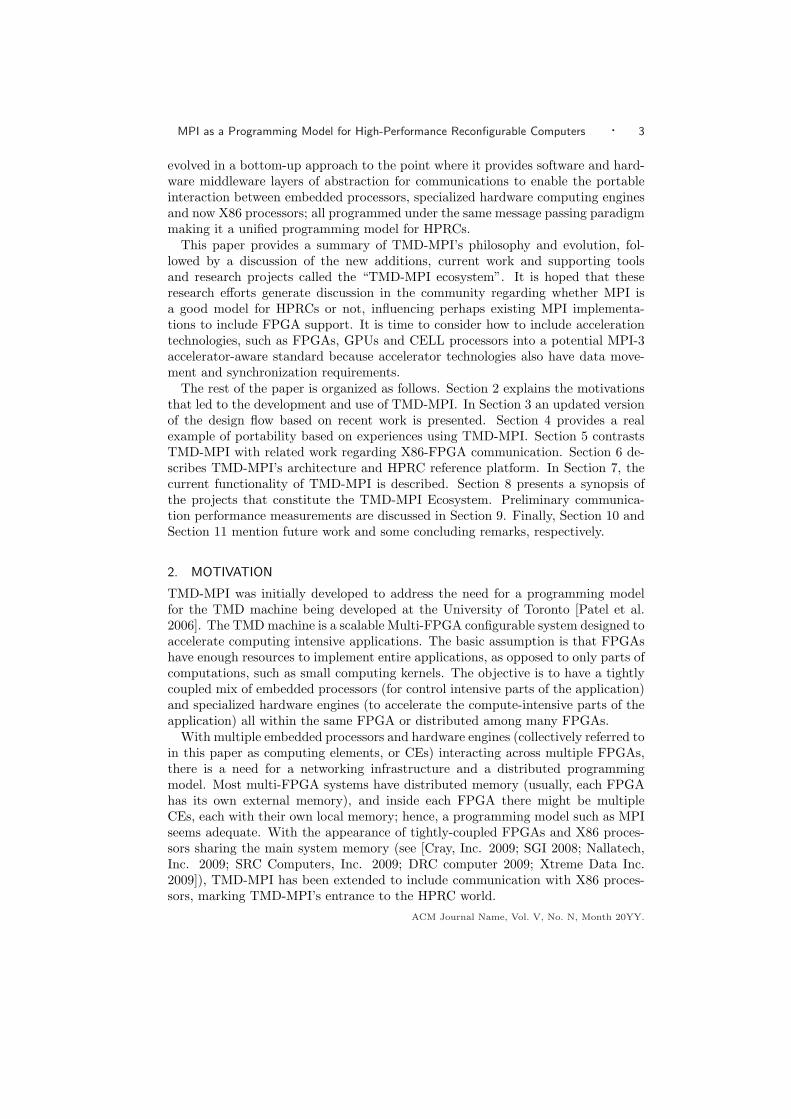
In the case of the HW-HW test, there are two additional possibilities based ontheir physical location. Both HW ranks can be in the same FPGA or they can be indifferent FPGAs. In a system using the Xilinx-ACP platform these two FPGAs canbe two base FPGAs (two M2B modules) or two compute FPGAs (one M2C module),or even one base FPGA and one compute FPGA (one M2B and one M2C module).Since the FPGAs are all connected through a high-speed LVDS core, we don’texpect to see any significant difference (4 to 6 additional cycles) compared to theoption where both HW ranks are implemented in the same FPGA. More interestingis to measure two FPGAs communicating through FSB. For these reasons, theACM Journal Name, Vol. V, No. N, Month 20YY.

MPI as a Programming Model for High-Performance Reconfigurable Computers · 21
main() {...MPI_Init();...if ( my_rank == rankA ) {
for(i=0; i<STEPS; i++) {
// ----- Synchronize -----MPI_Recv(NULL, 0, MPI_INT, rankB, SYNC_TAG, MPI_COMM_WORLD, &status);MPI_Send(NULL, 0, MPI_INT, rankB, SYNC_TAG, MPI_COMM_WORLD);
// ----- Main loop -----t1 = MPI_Wtime();for(sample=0; sample < SAMPLES; ++sample) {
MPI_Send(buf,msg_size[i],MPI_INT, rankB, sample, MPI_COMM_WORLD);MPI_Recv(buf,msg_size[i],MPI_INT, rankB, sample, MPI_COMM_WORLD, &status);
}t2 = MPI_Wtime();delta_t = (double)((t2-t1)/(2.0*SAMPLES));BandWidth = sizeof(int)*msg_size[i]/delta_t;...
}}else if ( my_rank == rankB ) {
for(i=0; i<STEPS; i++) {
// ----- Synchronize -----MPI_Send(NULL, 0, MPI_INT, rankA, SYNC_TAG, MPI_COMM_WORLD);MPI_Recv(NULL, 0, MPI_INT, rankA, SYNC_TAG, MPI_COMM_WORLD, &status);
// ----- Main loop -----t1 = MPI_Wtime();for(sample=0; sample < SAMPLES; ++sample) {
MPI_Recv(buf,msg_size[i],MPI_INT, rankA, sample, MPI_COMM_WORLD, &status);MPI_Send(buf,msg_size[i],MPI_INT, rankA, sample, MPI_COMM_WORLD);
}t2 = MPI_Wtime();delta_t = (double)((t2-t1)/(2.0*SAMPLES));BandWidth = sizeof(int)*msg_size[i]/delta_t;...
}}...MPI_Finalize();
}
Fig. 13. MPI pseudo-code for the round-trip message testbench
HW-HW test is performed for intra-M2B module communication (same FPGA)and inter-M2B module communication (different FPGAs on different modules).Figure 14 depicts the configuration tests for the experiment.
Note that from the HW rank’s perspective it is transparent where they are lo-cated; the HDL code of the HW engine does not change. It is the routing tablesfor the on-chip network that changes to let the network route the messages to theappropriate destination. The routing tables are stored in BRAM memory and theircontent in the bitstream can be updated with no need to rerun place and route.
The hardware engine is hand-written in VHDL and it implements a state machinethat follows the same algorithm as in the C code.
ACM Journal Name, Vol. V, No. N, Month 20YY.
22 · Manuel Saldana et al.
MEM
FPGA
X86
(a) X86-X86
X86
MEM
FPGA
(b) X86-M2B
X86 MEM
FPGA
(c) Intra-M2B
X86 MEM
FPGA FPGA
(d) Inter-M2B
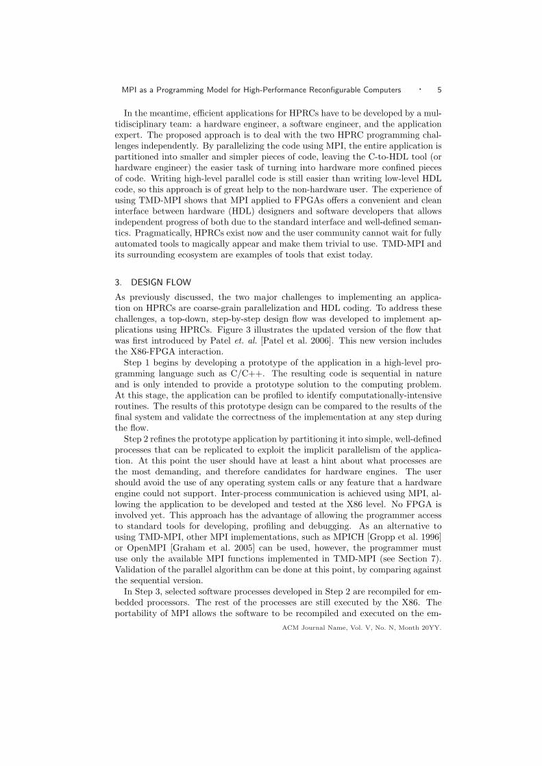
Fig. 14. Round-Trip experiments between two ranks mapped to different types and locations
9.2 Latency Results
We define message latency as the time it takes to send a zero-length message fromone rank to another. It is an important metric because for small messages andsynchronization operations, such as barriers, the latency is the predominant factorin the communication time. The latency will measure the overhead of calling theMPI functions (for software ranks) and calling the MPE (for hardware ranks) aswell as the network latency.
In TMD-MPI, a zero-length message means there is synchronization (i.e., syn-chronization packets are exchanged) but no actual data transfer. TMD-MPI usesthe rendezvous communication mode to transfer messages, which is a 3-way syn-chronous protocol. There is always a request-to-send packet and a clear-to-sendpacket before the actual data is transferred.
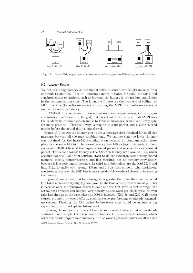
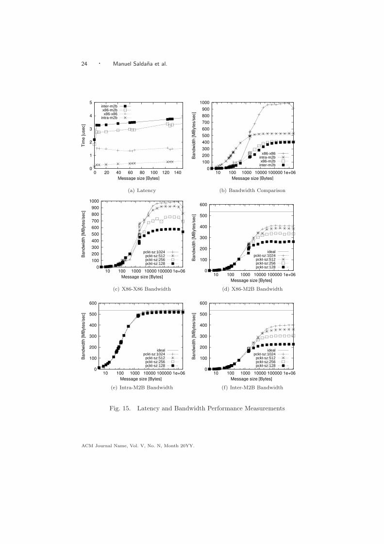
Figure 15(a) shows the latency plot (time vs message size) obtained for small-sizemessages between all the rank combinations. We can see that the lowest latencywas obtained for the intra-M2B configuration because all communication takesplace in the same FPGA. The lowest latency was 160 ns (approximately 21 clockcycles at 133MHz) to send the request-to-send packet and receive the clear-to-sendpacket. The second lowest latency is the X86-X86 latency with around 1 µs, whichaccounts for the TMD-MPI software stack to do the synchronization using sharedmemory; mostly pointer accesses and flag checking, but no memory copy occursbecause it is a zero-length message. In third and forth place are the X86-M2B andinter-M2B latencies with around 1.8 µs and 2.1 µs, respectively. The rendezvoussynchronization over the FSB bus incurs considerable overhead therefore increasingthe latency.
In general, we can see that for message sizes greater than zero the time the roundtrip takes increases very slightly compared to the time of the previous message. Thisis because once the synchronization is done and the first word is sent through, theactual data transfer can happen very quickly at one word per clock cycle, or eventake less time as in the case where an X86 is involved (X86-86 and X86-M2B tests)caused probably by cache effects, such as cache pre-fetching or already warmed-up caches. Flushing the X86 caches before every step would be an interestingexperiment, but it is kept for future work.
By using the rendezvous protocol there is an increased latency, but it has its ad-vantages. For example, there is no need to buffer entire unexpected messages, whichotherwise would require more memory. It also avoids potential buffer overflows dueACM Journal Name, Vol. V, No. N, Month 20YY.

MPI as a Programming Model for High-Performance Reconfigurable Computers · 23
to a lack of memory. This makes the rendezvous protocol more scalable memory-wise. There are other communication modes in MPI, such as Buffered mode andReady mode that can be implemented in TMD-MPI to reduce the latency, butexplaining them is beyond the scope of this paper.
9.3 Bandwidth Results
As opposed to a latency test where the messages are small, the bandwidth testrequires large messages to measure the transfer rate; however, the latency alsoaffects the message throughput. The bandwidth was determined by dividing themessage size by the total elapsed time divided by the number of samples. Notethat this time also considers the synchronization time, which is more realistic towhat one would experience in a normal application compared to just measuring theactual data transfer phase.
We identify three key factors for performance: synchronization, physical struc-ture of the communication channel and packetization/depacketization overhead.The later will be discussed in Section 9.4. The physical structure of the channeldetermines its peak bandwidth. In the case of the X86-X86 it would be determinedby how fast we can transfer data to/from memory. In the case of the on-chip com-munication, it would be determined by the product of the frequency times the widthof the communication channel. In our case, the on-chip channels are 32-bits wideFSLs clocked at 133 MHz, which gives a peak on-chip bandwidth of 533.33 MB/s.
In Figure 15(b) we can see how the tests that involve the HW rank are limited tobe under 533.33 MB/s, whereas the X86 achieves considerably higher bandwidths,at just under 1 GB/s. This probably happens because there are cache-to-cachetransfers of data in the Xeon quad-core chip, avoiding access to main memory,which is not the case in the HW test configurations, which always have to accessmain memory. In addition, there is of course the frequency difference of 1.6 GHzof the X86 core compared to the 133.33 MHz at which the FPGA is clocked.
The effect of synchronization is reflected in the bandwidth plot as a measureof how fast the saturation bandwidth point is reached. With an ideal zero-timesynchronization the bandwidth plot would be a horizontal line. From Figure 15(a),we know the intra-M2B latency is lower than the X86-X86 latency, therefore, theintra-M2B bandwidth is higher than the X86-X86 bandwidth for small messages asshown in Figure 15(b). After a certain size, the frequency and width of the channelbecomes a more predominant factor causing the intra-M2B to reach the saturatingbandwidth point earlier.
For inter-M2B and X86-M2B configurations the bandwidth is still limited bythe on-chip bandwidth in addition to the extra latency of accessing main memory,which accounts for the actual latency of the memory requests passing throughthe North Bridge, to the actual memory chips and back to the FPGA, as wellas the latency for the Intel-Xilinx FSB core plus the MPI FSB Bridge. Once thebandwidth is saturated the difference compared to the peak bandwidth is explainedby the packetization/depacketization process, as explained in the next section.
9.4 Packet Size Impact on Bandwidth
Large messages in TMD-MPI are split into packets of smaller size to be able touse the packet-based network. However, the packetizing/depacketizing process in-
ACM Journal Name, Vol. V, No. N, Month 20YY.
24 · Manuel Saldana et al.
0
1
2
3
4
5
0 20 40 60 80 100 120 140
Tim
e [usec]
Message size [Bytes]
inter-m2bx86-m2bx86-x86
intra-m2b
(a) Latency
0
100
200
300
400
500
600
700
800
900
1000
10 100 1000 10000 100000 1e+06
Bandw
idth
[M
Byte
s/s
ec]
Message size [Bytes]
x86-x86intra-m2bx86-m2b
inter-m2b
(b) Bandwidth Comparison
0
100
200
300
400
500
600
700
800
900
1000
10 100 1000 10000 100000 1e+06
Bandw
idth
[M
Byte
s/s
ec]
Message size [Bytes]
pckt-sz:1024pckt-sz:512pckt-sz:256pckt-sz:128
(c) X86-X86 Bandwidth
0
100
200
300
400
500
600
10 100 1000 10000 100000 1e+06
Bandw
idth
[M
Byte
s/s
ec]
Message size [Bytes]
idealpckt-sz:1024
pckt-sz:512pckt-sz:256pckt-sz:128
(d) X86-M2B Bandwidth
0
100
200
300
400
500
600
10 100 1000 10000 100000 1e+06
Bandw
idth
[M
Byte
s/s
ec]
Message size [Bytes]
idealpckt-sz:1024
pckt-sz:512pckt-sz:256pckt-sz:128
(e) Intra-M2B Bandwidth
0
100
200
300
400
500
600
10 100 1000 10000 100000 1e+06
Bandw
idth
[M
Byte
s/s
ec]
Message size [Bytes]
idealpckt-sz:1024
pckt-sz:512pckt-sz:256pckt-sz:128
(f) Inter-M2B Bandwidth
Fig. 15. Latency and Bandwidth Performance Measurements
ACM Journal Name, Vol. V, No. N, Month 20YY.

MPI as a Programming Model for High-Performance Reconfigurable Computers · 25
troduces an overhead in performance decreasing the achievable bandwidth. Thiseffect can be seen in the bandwidth plots (Figures 15(d),15(e) and 15(f)) as thedifference between the peak ideal bandwidth and the saturation bandwidth point.Therefore, the packet size is an important factor in communication performance.Large packet sizes will result in higher bandwidths, but also will incur more resourceusage (memory and logic resources in the FPGAs).
To analyze the impact of packet size in bandwidth, the same round trip messageexperiment as in Section 9.3 is repeated but with different packet sizes: 128, 256,512 and 1024 words per packet (each words is 32-bits wide).
Figures 15(c),15(d),15(e) and 15(f) show the bandwidth plot for the X86-X86,X86-M2B, Intra-M2B and Inter-M2B tests, respectively. The x-axis uses a logscale and it represents the message size. Notice that in all the cases the packetsize increases the bandwidth considerably, however, this increase is not directlyproportional. By doubling the packet size there is not a corresponding doubling inbandwidth. For example, in Figure 15(f), with a packet size of 128 words/packet thebandwidth saturates at 227MB/s, and with a packet size of 256 words/packet thebandwidth saturates at 304 MB/s; this is only a 33.9%improvement. Furthermore,as the packet size keeps increasing by a factor of two, from 128 to 256 to 512 to 1024the observed improvement in bandwidth compared to the previous packet sizes are33.9%, 19%, 10.6%, respectively; the benefits in additional bandwidth decreases asit asymptotically approaches the peak bandwidth.
In the particular case of intra-M2B, the packetizing/depacketizing overhead isminimal achieving 531.2 MB/s, which means 99.6% of the peak bandwidth. Keepin mind that the peak bandwidth is 533.33 MB/s (32-bits wide channels @133MHz). In contrast, the X86-M2B and inter-M2B achieve 410 MB/s (77% of peakbandwidth) and 400 MB/s (75% of peak bandwidth), respectively. This happensbecause in addition to the 533MB/s limitation, there is an additional overheadto read and write to shared memory buffers to exchange data, which can only bewritten or read at one time. A double buffering technique should alleviate thisproblem, of course at the expense of more memory requirements.
Finally, we can see that in all the plots in Figure 15 the tests in which the X86 isinvolved are noisier than those with only FPGAs. This is because FPGAs do notuse a cache, making their communication more predictable as there are no jumpsdue to cache artifacts or operating system interference, such as time slicing andprocess scheduling, even though the measurements were taken when nothing elsewas running in the system.
10. FUTURE PERSPECTIVES
All together, TMD-MPI and its ecosystem are here and they provide a usableenvironment. The main focus now will be on expanding TMD-MPI’s functionalityas we use it for more and more applications. Unfortunately, the Molecular Dynamicsapplication is not complete yet and performance results will be reported in a futurepublication as it would require further discussion, which is beyond the scope of hispaper.
Naturally, performance improvements are scheduled targeting reduced latencyand increased bandwidth, while keeping in mind the application requirements to
ACM Journal Name, Vol. V, No. N, Month 20YY.
26 · Manuel Saldana et al.
maintain TMD-MPI as lightweight as possible. To do this, we will use more com-plete benchmarks, closer to existing MPI benchmarks, but adapted to use recon-figurable hardware. Existing benchmarks are designed to run on X86 processorswith operating systems, which is not always the case with embedded processorsand definitely not the case with hardware engines.
As shown in Section 9, the primary limitation of the bandwidth is due to the32-bit, on-chip channels, however, results are promising given the current configu-ration. Future versions of TMD-MPI will provide 64, 128 and 256-bit wide channels,that should increase the bandwidth by two-fold, four-fold or eight-fold, respectively.In addition, increasing the frequency from 133 MHz to 266 MHz should also addanother factor of two to the performance. The raw bandwidth available to theM2B module from the FSB bus is 8.5GB/s allowing plenty of opportunities to im-prove the performance by architectural enhancements and the use of more efficientprotocols.
Additionally, we have the difficult task of convincing two different audiences, Soft-ware people and Hardware people, of the benefits of using TMD-MPI. Sometimes,hardware people do not understand how a typical software coarse-grain parallelprogramming API can help in hardware design, and software people sometimes donot understand how MPI can be used in a hardware environment. For this, futurework includes writing documentation for both audiences and future papers withcase examples of applications that use TMD-MPI.
11. CONCLUSION
TMD-MPI opens new research opportunities to implement an efficient MPI pro-gramming model for HPRCs, including hardware support for message-passing tak-ing advantage of FPGA flexibility. In this paper, the ideas and tools that supportMPI as a feasible programming model that abstracts the communications in aHPRC have been presented. The fact that MPI is based on a well-known andsuccessful standard makes it even more appealing for parallel software developers.
TMD-MPI is not an exclusive idea; quite the opposite, it builds on top of otherprojects and vice-versa. It can benefit from OpenFPGA’s API standardization ef-forts, C-to-HDL tools while encouraging their improvements, new simulation tech-niques, new software/hardware profiling methods, and nothing prevents the use ofa mixed shared memory plus MPI programming approach, if that helps to raise theprogramming abstraction. MPI provides a standard API and a common program-ming model for both software and hardware people while promoting scalability,portability and collaboration across HPRCs.
The performance measurements obtained in this paper, while still preliminary,are valuable metrics to drive continued improvement of TMD-MPI and assess theimpact of such improvements. TMD-MPI has been used and developed as a proof-of-concept implementation. Although it is still work in progress, it is currentlybeing used to code an MD application in an HPRC.
ACKNOWLEDGMENTS
We acknowledge the CMC/SOCRN, NSERC and Xilinx for the hardware, tools andfunding provided for this project. Thanks to Vincent Mirian for his collaborationACM Journal Name, Vol. V, No. N, Month 20YY.

MPI as a Programming Model for High-Performance Reconfigurable Computers · 27
and feedback.
REFERENCES
Aggarwal, V., Troxel, I. A., and George, A. D. 2004. Design and Analysis of Parallel N-Queens on Reconfigurable Hardware with Handel-C and MPI. In 2004 MAPLD InternationalConference. Washington, DC, USA.
Amirix Systems, Inc. 2009. http://www.amirix.com/ [Accessed: March, 2009].
Callahan, D., Chamberlain, B., and Zima, H. 2004. The Cascade High Productivity Language.High-Level Parallel Programming Models and Supportive Environments, 2004. Proceedings.Ninth International Workshop on, 52–60.
Chang, C., Wawrzynek, J., and Brodersen, R. W. 2005. BEE2: A High-End ReconfigurableComputing System. IEEE Des. Test ’05 22, 2, 114–125.
Comis, C. 2005. A High-Speed Inter-Process Communication Architecture for FPGA-based Hard-ware Acceleration of Molecular Dynamics. M.S. thesis, University of Toronto.
Cray Inc. 2005. CRAY XD1 FPGA Development. CRAY Inc. pp. 9-11, pp. 63-66.
CRAY, Inc. 2009. http://www.cray.com/ [Accessed: March, 2009].
Cray, Inc. 2009. Cray XT5h Supercomputer Brochure. http://www.cray.com/Assets/PDF/
products/xt/CrayXT5hBrochure.pdf [Accessed: March, 2009].
DRC computer. 2009. http://www.drccomputer.com/ [Accessed: March, 2009].
Ebcioglu, Saraswat, and Sarkar. 2005. X10: an Experimental Language for High Produc-tivity Programming of Scalable Systems. Second International Workshop on Productivity andPerformance in High-End Computing (P-PHEC).
Graham, R. L., Woodall, T. S., and Squyres, J. M. 2005. Open MPI: A Flexible HighPerformance MPI. In Proceedings, 6th Annual International Conference on Parallel Processingand Applied Mathematics. Poznan, Poland.
Gropp, W., Lusk, E., Doss, N., and Skjellum, A. 1996. A high-performance, portable im-plementation of the MPI message passing interface standard. Parallel Computing 22, 6 (sep),789–828.
HyperTransport Consortium. 2009. http://www.hypertransport.org [Accessed: March,2009].
Impulse Accelerated Technologies, Inc. 2009. http://www.impulsec.com [Accessed: March,2009].
Intel. 2009a. Intel Quick Path Architecture (White Paper). http://www.intel.com/technology/quickpath/whitepaper.pdf [Accessed: March, 2009].
Intel. 2009b. Intel QuickAssist Technology AAL (White Paper). http://download.
intel.com/technology/platforms/quickassist/quickassist_aal_whitepaper.pdf [Accessed:March, 2009].
Intel, Corp. 2009. http://www.intel.com/ [Accessed: March, 2009].
Jerraya, A. and Wolf, W. 2004. Multiprocessor Systems-on-Chip. Morgan Kaufmannn.
Mentor Graphics. 2009. http://www.mentor.com/ [Accessed: March, 2009].
Mitrionics, Inc. 2009. http://www.mitrionics.com [Accessed: March, 2009].
Moore, N., Conti, A., Leeser, M., and King, L. 2007. Vforce: An Extensible Framework forReconfigurable Supercomputing. Computer 40, 3 (March), 39–49.
MPI Parallel Environment. 2008. http://www-unix.mcs.anl.gov/perfvis/software/MPE/
index.html.
Nallatech, Inc. 2009. http://www.nallatech.com/ [Accessed: March, 2009].
Nunes, D., Saldana, M., and Chow, P. 2008. A Profiler for a Heterogeneous Multi-Core Multi-FPGA System. In In Proceedings of the International Conference on Field-ProgrammableTechnology. IEEE, Taipei, Taiwan.
openfpga 2009. OpenFPGA. http://www.openfpga.org/ [Accessed: March, 2009].
OpenFPGA 2009. OpenFPGA GenAPI version 0.4 Draft For Comment. http://www.openfpga.
org/pages/Standards.aspx [Accessed: March, 2009].
ACM Journal Name, Vol. V, No. N, Month 20YY.

28 · Manuel Saldana et al.
Patel, A., Madill, C. A., Saldana, M., Comis, C., Pomes, R., and Chow, P. 2006. A ScalableFPGA-based Multiprocessor. In Proceedings of the 14th Annual IEEE Symposium on Field-Programmable Custom Computing Machines. FCCM’06., 111–120.
Project Fortress Community. 2009. http://projectfortress.sun.com/Projects/
Community/ [Accessed: March, 2009].
Saldana, M. 2006. A Parallel Programming Model for a Multi-FPGA Multiprocessor Machine.M.S. thesis, University of Toronto.
Saldana, M. and Chow, P. 2006. TMD-MPI: An MPI Implementation for Multiple ProcessorsAcross Multiple FPGAs. In In Proceedings of the 16th International Conference on Field-Programmable Logic and Applications. IEEE, Madrid, Spain.
Saldana, M., Nunes, D., Ramalho, E., and Chow, P. 2006. Configuration and Programmingof Heterogeneous Multiprocessors on a Multi-FPGA System Using TMD-MPI. In In the Pro-ceedings of the 3rd International Conference on Reconfigurable Computing and FPGAs. IEEE,San Luis Potosi, Mexico.
Saldana, M., Ramalho, E., and Chow, P. 2008. A Message-passing Hardware/Software Co-simulation Environment to Aid in Reconfigurable Computing Design using TMD-MPI. InProceeding of the International Conference on Reconfigurable Computing and FPGAs. ReCon-Fig’08. IEEE, Cancun, Mexico.
SGI. 2008. Reconfigurable Application-Specific Computing Users Guide. SGI. pp. 9-12, pp.223-244.
SGI. 2008. SGI RASC RC100 Blade. http://www.sgi.com/pdfs/3920.pdf [Accessed: March,2009].
SGI. 2009. http://www.sgi.com/ [Accessed: March, 2009].
SRC Computers, Inc. 2009. http://www.srccomp.com/ [Accessed: March, 2009].
Synfora, Inc. 2009. http://www.synfora.com [Accessed: March, 2009].
The MPI Forum. 1993. MPI: a Message Passing Interface. In Supercomputing ’93: Proceedingsof the 1993 ACM/IEEE conference on Supercomputing. ACM Press, New York, NY, USA,878–883.
Wang, D. 2008. An Automated Flow to Generate Hardware Computing Nodes from C for anFPGA-Based MPI Computing Network. Engineering Science Undergraduate Thesis, Universityof Toronto.
Xtreme Data Inc. 2009. http://www.xtremedatainc.com/ [Accessed: March, 2009].
Zaki, O., Lusk, E., Gropp, W., and Swider, D. 1999. Toward Scalable Performance Visualiza-tion with Jumpshot. Int. J. High Perform. Comput. Appl. 13, 3, 277–288.
Received Month Year; revised Month Year; accepted Month Year
ACM Journal Name, Vol. V, No. N, Month 20YY.