Motion features to enhance scene segmentation in active visual attention
10
Motion features to enhance scene segmentation in active visual attention Marı ´a T. Lo ´pez a , Antonio Ferna ´ndez-Caballero a, * , Miguel A. Ferna ´ndez a , Jose ´ Mira b , Ana E. Delgado b a Departamento de Informa ´ tica, Escuela Polite ´cnica Superior, Universidad de Castilla-La Mancha, 02071 Albacete, Spain b Departamento de Inteligencia Artificial, Facultad de Ciencias and E.T.S.I. Informa ´ tica, Universidad Nacional de Educacio ´ n a Distancia, 28040 Madrid, Spain Received 12 November 2003; received in revised form 25 July 2005 Available online 20 October 2005 Communicated by T.K. Ho Abstract A new computational model for active visual attention is introduced in this paper. The method extracts motion and shape features from video image sequences, and integrates these features to segment the input scene. The aim of this paper is to highlight the importance of the motion features present in our algorithms in the task of refining and/or enhancing scene segmentation in the method proposed. The estimation of these motion parameters is performed at each pixel of the input image by means of the accumulative computation method, using the so-called permanency memories. The paper shows some examples of how to use the ‘‘motion presence’’, ‘‘module of the velocity’’ and ‘‘angle of the velocity’’ motion features, all obtained from accumulative computation method, to adjust different scene segmentation outputs in this dynamic visual attention method. Ó 2005 Elsevier B.V. All rights reserved. Keywords: Active visual attention; Permanency memories; Segmentation; Feature extraction; Motion; Image sequences 1. Introduction Motion is a major information source for segmenting objects perceived in dynamic scenes. Therefore, techniques for estimating the velocity field (optical flow field) are of great interest for enhancing scene segmentation (Gautama and Van Hulle, 2002). In previous works, our research team has taken advantage of motion information in seg- menting (Ferna ´ndez-Caballero et al., 2001, 2003) and clas- sifying moving objects (Ferna ´ndez et al., 2003) through accumulative computation (Ferna ´ndez et al., 1995) and algorithmic lateral inhibition (Mira et al., 2004) by means of a series of charge maps related to pixel-wise ‘‘motion presence’’ information. But, up to this moment, we had not directly used calculated motion parameters—e.g. veloc- ity parameters, such as the ‘‘module of the velocity’’ and the ‘‘angle of the velocity’’—to perform better and more robust segmentation and tracking in video sequences. Our latest research deals with dynamic visual attention sys- tems, where parameters of this kind have turned out to be necessary. In this paper, we introduce a new active visual attention method for scene segmentation. Although the whole struc- ture of the system is described briefly, we highlight the importance of motion-related parameters. In this sense, a great emphasis is placed on the Motion Features Extraction task within the overall Active Visual Attention proposed method. The layout of the paper is as follows. In Section 2, the proposed active visual attention method is described. In Section 3, we offer a series of data and results, including a performance evaluation on the famous Hamburg Taxi 0167-8655/$ - see front matter Ó 2005 Elsevier B.V. All rights reserved. doi:10.1016/j.patrec.2005.09.010 * Corresponding author. Tel.: +34 967 599 200; fax: +34 967 599 224. E-mail address: [email protected] (A. Ferna ´ndez-Caballero). www.elsevier.com/locate/patrec Pattern Recognition Letters 27 (2006) 469–478
-
Upload
independent -
Category
Documents
-
view
5 -
download
0
Transcript of Motion features to enhance scene segmentation in active visual attention
www.elsevier.com/locate/patrec
Pattern Recognition Letters 27 (2006) 469–478
Motion features to enhance scene segmentationin active visual attention
Marıa T. Lopez a, Antonio Fernandez-Caballero a,*, Miguel A. Fernandez a,Jose Mira b, Ana E. Delgado b
a Departamento de Informatica, Escuela Politecnica Superior, Universidad de Castilla-La Mancha, 02071 Albacete, Spainb Departamento de Inteligencia Artificial, Facultad de Ciencias and E.T.S.I. Informatica, Universidad Nacional de Educacion a Distancia,
28040 Madrid, Spain
Received 12 November 2003; received in revised form 25 July 2005Available online 20 October 2005
Communicated by T.K. Ho
Abstract
A new computational model for active visual attention is introduced in this paper. The method extracts motion and shape featuresfrom video image sequences, and integrates these features to segment the input scene. The aim of this paper is to highlight the importanceof the motion features present in our algorithms in the task of refining and/or enhancing scene segmentation in the method proposed.The estimation of these motion parameters is performed at each pixel of the input image by means of the accumulative computationmethod, using the so-called permanency memories. The paper shows some examples of how to use the ‘‘motion presence’’, ‘‘moduleof the velocity’’ and ‘‘angle of the velocity’’ motion features, all obtained from accumulative computation method, to adjust differentscene segmentation outputs in this dynamic visual attention method.� 2005 Elsevier B.V. All rights reserved.
Keywords: Active visual attention; Permanency memories; Segmentation; Feature extraction; Motion; Image sequences
1. Introduction
Motion is a major information source for segmentingobjects perceived in dynamic scenes. Therefore, techniquesfor estimating the velocity field (optical flow field) are ofgreat interest for enhancing scene segmentation (Gautamaand Van Hulle, 2002). In previous works, our researchteam has taken advantage of motion information in seg-menting (Fernandez-Caballero et al., 2001, 2003) and clas-sifying moving objects (Fernandez et al., 2003) throughaccumulative computation (Fernandez et al., 1995) andalgorithmic lateral inhibition (Mira et al., 2004) by meansof a series of charge maps related to pixel-wise ‘‘motionpresence’’ information. But, up to this moment, we had
0167-8655/$ - see front matter � 2005 Elsevier B.V. All rights reserved.
doi:10.1016/j.patrec.2005.09.010
* Corresponding author. Tel.: +34 967 599 200; fax: +34 967 599 224.E-mail address: [email protected] (A. Fernandez-Caballero).
not directly used calculated motion parameters—e.g. veloc-ity parameters, such as the ‘‘module of the velocity’’ andthe ‘‘angle of the velocity’’—to perform better and morerobust segmentation and tracking in video sequences.Our latest research deals with dynamic visual attention sys-tems, where parameters of this kind have turned out to benecessary.
In this paper, we introduce a new active visual attentionmethod for scene segmentation. Although the whole struc-ture of the system is described briefly, we highlight theimportance of motion-related parameters. In this sense, agreat emphasis is placed on the Motion Features Extraction
task within the overall Active Visual Attention proposedmethod. The layout of the paper is as follows. In Section2, the proposed active visual attention method is described.In Section 3, we offer a series of data and results, includinga performance evaluation on the famous Hamburg Taxi
470 M.T. Lopez et al. / Pattern Recognition Letters 27 (2006) 469–478
sequence. Section 4 shows the main conclusions for thisarticle.
2. Active visual attention method
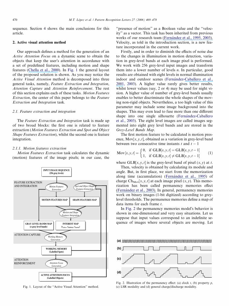
Our approach defines a method for the generation of anActive Attention Focus on a dynamic scene to obtain theobjects that keep the user�s attention in accordance witha set of predefined features, including motion and shapefeatures (Chella et al., 2000). In Fig. 1 the general layoutof the proposed solution is shown. As you may notice theActive Visual Attention method is decomposed into threegeneral tasks, namely, Feature Extraction and Integration,Attention Capture and Attention Reinforcement. The restof this section explains each of these tasks.Motion Features
Extraction, the center of this paper belongs to the Feature
Extraction and Integration task.
2.1. Feature extraction and integration
The Feature Extraction and Integration task is made upof two broad blocks: the first one is related to featureextraction (Motion Features Extraction and Spot and Object
Shape Features Extraction), whilst the second one is featureintegration.
2.1.1. Motion features extraction
Motion Features Extraction task calculates the dynamic(motion) features of the image pixels; in our case, the
ATTENTION REINFORCEMENT
ATTENTION CAPTURE
FEATURE EXTRACTION AND INTEGRATION
INPUT IMAGE SEQUENCE(256 gray levels)
GRAY LEVEL BANDS MAP(n gray level bands)
Motion Features Extraction
MOTION FEATURES MAP
Spot and Object Shape Features Extraction
SHAPE FEATURES MAP
Motion and Shape Features Integration
INTEREST MAP(vactive , vinhibited , vneutral)
Working Memory Generation
WORKING MEMORY(Labelled Spots)
Attention Focus Generation
ACTIVE ATTENTION FOCUS(Labelled Objects)
Fig. 1. Layout of the ‘‘Active Visual Attention’’ method.
‘‘presence of motion’’ as a Boolean value and the ‘‘veloc-ity’’ as a vector. This task has been inherited from previousworks of our research team (Fernandez et al., 1995, 2003).Velocity, as told in the introduction section, is a new fea-ture incorporated in the current work.
Firstly, and in order to diminish the effects of noise dueto the changes in illumination in motion detection, varia-tion in grey-level bands at each image pixel is performed.We work with 256 grey-level input images and transformthem into a lower number of levels n. In particular, goodresults are obtained with eight levels in normal illuminationindoor and outdoor scenes (Fernandez-Caballero et al.,2001, 2003). A higher value rarely gives better results,whilst lower values (say, 2 or 4) may be used for night vi-sion. A higher value of number of grey-level bands usuallyenables to better discriminate the whole shapes of the mov-ing non-rigid objects. Nevertheless, a too high value of thisparameter may include some image background into theshapes. This may even lead to fuse more than one differentshape into one single silhouette (Fernandez-Caballeroet al., 2003). The eight level images are called images seg-mented into eight grey level bands and are stored in theGrey-Level Bands Map.
The first motion feature to be calculated is motion pres-ence, Mov[x,y, t], obtained as a variation in grey-level bandbetween two consecutive time instants t and t � 1
Mov ½x; y; t� ¼0; if GLB½x; y; t� ¼GLB½x; y; t� 1�1; if GLB½x; y; t� 6¼GLB½x; y; t� 1�
�ð1Þ
where GLB[x,y, t] is the grey-level band of pixel (x,y) at t.Then, velocity is obtained by calculating its module and
angle. But, in first place, we start from the memorizationalong time (accumulation) (Fernandez et al., 1995) ofcharge ChMov[x,y, t] at each image pixel (x,y). This memo-rization has been called permanency memories effect(Fernandez et al., 2003). In general, permanency memorieswork on binary images (1-bit digitized) according to grey-level thresholds. The permanence memories define a map ofdata items for each frame t.
In Fig. 2 the permanency memories model�s behavior isshown in one-dimensional and very easy situations. Let ussuppose that input values correspond to an indefinite se-quence of images where several objects are moving. Let
Fig. 2. Illustration of the permanency effect: (a) clock t, (b) property p,(c) LSR modality and (d) general charge/discharge modality.

Fig. 3. A graphical view of the contents of the permanency memory after25 image frames.
Table 1Description of the relationship between permanence values and motiondetection
Value in motioncharge memory
Explanation
ChMov[x,y, t] = Chmin Motion is detected at pixel [x,y] in t. Value inmemory is the minimum charge value
ChMov[x,y, t]= Chmin + k Æ Cmotion
< Chmax
No motion is detected at pixel [x,y] in t.Motion was detected for the last time int � k Æ Dt. After k charge increments themaximum charge has not yet been reached
ChMov[x,y, t] = Chmax No motion is detected at pixel [x,y] in t. Wedo not know when motion was detected forthe last time. Value in memory is themaximum charge value
M.T. Lopez et al. / Pattern Recognition Letters 27 (2006) 469–478 471
us also suppose that a measured property, p[x,y, t] is theresult of detecting motion on pixel (x,y) at time instant t.Then, values of p[x,y, t] in two successive instants are used,interpreting that p[x,y, t] = 1 means that motion has beendetected over pixel (x,y) at t and that p[x,y, t] = 0 meansthere is no motion. For this property, the evolution ofcharge and discharge of its persistency is shown in Fig. 2for some modalities. Fig. 2c shows the behavior of theaccumulative computation model in a modality calledLSR (length speed relation) (Fernandez et al., 2003). Thismodality has been used for the purpose of classificationof moving objects. The more general charge/dischargemodality is also shown (Fig. 2d).
Now, in this way, the value in frame t of the permanencymemory ChMov[x,y, t], associated to pixel (x,y) might bedefined in terms of its value at time t � 1 and the binaryinput Mov[x,y, t]. The accumulative computation opera-tion mode used in this case is the LSR mode applied onthe inverse of the property described. Thus, the propertymeasured in this case is equivalent to ‘‘no motion presence’’at pixel of co-ordinates (x,y) at instant t
p½x; y; t� ¼ 1�Mov½x; y; t� ð2Þ
Thus, in this work, the formula used to represent thecharge due to accumulative computation by permanencymemories is the following one:
ChMov½x; y; 0� ¼ Chmax
ChMov½x; y; t� ¼
Chmin;
if Mov½x; y; t� ¼ 1
minðChMov½x; y; t � 1�þCmotion;ChmaxÞ;if Mov½x; y; t� ¼ 0
8>>>>>>><>>>>>>>:
ð3Þ
In LSR mode Cmotion is called the charge incrementvalue. The idea is that if there is no motion on pixel(x,y), charge value ChMov[x,y, t] goes incrementing up toChmax, and if there is motion, there is a complete discharge(the charge value is given value Chmin). Usually, Chmax andChmin are chosen to be 255 and 0, respectively, that is tosay, the maximum and minimum value of any possible greylevel. This range has been kept as such since our first workson motion analysis as it fits in one single byte andconsumes little memory when dealing with large imagesequences. Thus, notice that charge value ChMov[x,y, t] rep-resents a measure of time elapsed since the last significantvariation in brightness on image pixel (x,y).
As an example let us consider the motion situation,where an object initially moves horizontally with twovelocities (first, 1 pixel each two frames; and then, 1 pixeleach four frames), and then continues moving verticallywith a velocity of 1 pixel per frame in a 20 · 20 pixel image.The basic parameters for the accumulative computationare: Chmax = 255, Chmin = 0, and Cmotion = 5. Fig. 3graphically shows the values for the permanency memoryat t = 25 (with a scale change Chmax � ChMov[x,y, 25]).
You may observe that the slope of the permanency remainsconstant while the velocity is constant at 1 pixel eachframe, and then augments when the velocity decrements(1 pixel each four frames). When considering the motionin the vertical axis, the slope is the lowest as the velocityis only 1 pixel per frame.
Once the charge map (or permanency memory) has beenobtained, velocity may be calculated starting from thesecharges stored, as explained in Table 1.
It is important to highlight that the velocity obtained inthis way is not the velocity of an object point that occupiespixel (x,y) in time t, but rather the velocity of an objectpoint that caused motion presence detection when it passedover pixel (x,y) a number
k ¼ ChMov½x; y; t� � Chmin
Cmotion
ð4Þ
of time units before. Thus, a given charge shows the samevalue for all those pixels where a simultaneous motion oc-curred at a given time. Now, in order to get the velocity wecalculate the velocity in x-axis, vx, as well as in y-axis, vy.Once values vx y vy, have been obtained, the module andthe angle of vector velocity are also got.
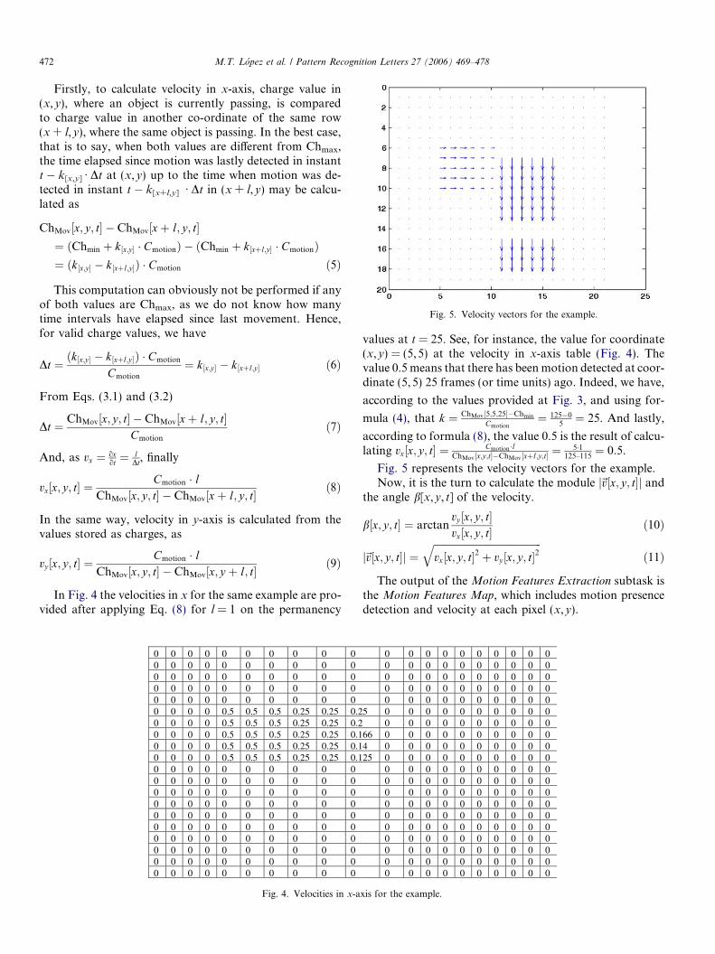
Fig. 5. Velocity vectors for the example.
472 M.T. Lopez et al. / Pattern Recognition Letters 27 (2006) 469–478
Firstly, to calculate velocity in x-axis, charge value in(x,y), where an object is currently passing, is comparedto charge value in another co-ordinate of the same row(x + l,y), where the same object is passing. In the best case,that is to say, when both values are different from Chmax,the time elapsed since motion was lastly detected in instantt � k[x,y] Æ Dt at (x,y) up to the time when motion was de-tected in instant t � k[x+l,y] Æ Dt in (x + l,y) may be calcu-lated as
ChMov½x; y; t� � ChMov½xþ l; y; t�¼ ðChmin þ k½x;y� � CmotionÞ � ðChmin þ k½xþl;y� � CmotionÞ¼ ðk½x;y� � k½xþl;y�Þ � Cmotion ð5Þ
This computation can obviously not be performed if anyof both values are Chmax, as we do not know how manytime intervals have elapsed since last movement. Hence,for valid charge values, we have
Dt ¼ ðk½x;y� � k½xþl;y�Þ � Cmotion
Cmotion
¼ k½x;y� � k½xþl;y� ð6Þ
From Eqs. (3.1) and (3.2)
Dt ¼ ChMov½x; y; t� � ChMov½xþ l; y; t�Cmotion
ð7Þ
And, as vx ¼ oxot ¼ l
Dt, finally
vx½x; y; t� ¼Cmotion � l
ChMov½x; y; t� � ChMov½xþ l; y; t� ð8Þ
In the same way, velocity in y-axis is calculated from thevalues stored as charges, as
vy ½x; y; t� ¼Cmotion � l
ChMov½x; y; t� � ChMov½x; y þ l; t� ð9Þ
In Fig. 4 the velocities in x for the same example are pro-vided after applying Eq. (8) for l = 1 on the permanency
0 0 0 0 0 0 0 0 0 00 0 0 0 0 0 0 0 0 00 0 0 0 0 0 0 0 0 00 0 0 0 0 0 0 0 0 00 0 0 0 0 0 0 0 0 00 0 0 0 0.5 0.5 0.5 0.25 0.25 0.20 0 0 0 0.5 0.5 0.5 0.25 0.25 0.20 0 0 0 0.5 0.5 0.5 0.25 0.25 0.10 0 0 0 0.5 0.5 0.5 0.25 0.25 0.10 0 0 0 0.5 0.5 0.5 0.25 0.25 0.10 0 0 0 0 0 0 0 0 00 0 0 0 0 0 0 0 0 00 0 0 0 0 0 0 0 0 00 0 0 0 0 0 0 0 0 00 0 0 0 0 0 0 0 0 00 0 0 0 0 0 0 0 0 00 0 0 0 0 0 0 0 0 00 0 0 0 0 0 0 0 0 00 0 0 0 0 0 0 0 0 00 0 0 0 0 0 0 0 0 0
Fig. 4. Velocities in x-a
values at t = 25. See, for instance, the value for coordinate(x,y) = (5,5) at the velocity in x-axis table (Fig. 4). Thevalue 0.5 means that there has been motion detected at coor-dinate (5,5) 25 frames (or time units) ago. Indeed, we have,
according to the values provided at Fig. 3, and using for-
mula (4), that k ¼ ChMov½5;5;25��Chmin
Cmotion¼ 125�0
5¼ 25. And lastly,
according to formula (8), the value 0.5 is the result of calcu-lating vx½x; y; t� ¼ Cmotion�l
ChMov½x;y;t��ChMov ½xþl;y;t� ¼ 5�1125–115
¼ 0:5.
Fig. 5 represents the velocity vectors for the example.Now, it is the turn to calculate the module j~v½x; y; t�j and
the angle b[x,y, t] of the velocity.
b½x; y; t� ¼ arctanvy ½x; y; t�vx½x; y; t�
ð10Þ
j~v½x; y; t�j ¼ffiffiffiffiffiffiffiffiffiffiffiffiffiffiffiffiffiffiffiffiffiffiffiffiffiffiffiffiffiffiffiffiffiffiffiffiffiffiffiffiffiffiffivx½x; y; t�2 þ vy ½x; y; t�2
qð11Þ
The output of the Motion Features Extraction subtask isthe Motion Features Map, which includes motion presencedetection and velocity at each pixel (x,y).
0 0 0 0 0 0 0 0 0 00 0 0 0 0 0 0 0 0 00 0 0 0 0 0 0 0 0 00 0 0 0 0 0 0 0 0 00 0 0 0 0 0 0 0 0 0
5 0 0 0 0 0 0 0 0 0 00 0 0 0 0 0 0 0 0 0
66 0 0 0 0 0 0 0 0 0 04 0 0 0 0 0 0 0 0 0 025 0 0 0 0 0 0 0 0 0 0
0 0 0 0 0 0 0 0 0 00 0 0 0 0 0 0 0 0 00 0 0 0 0 0 0 0 0 00 0 0 0 0 0 0 0 0 00 0 0 0 0 0 0 0 0 00 0 0 0 0 0 0 0 0 00 0 0 0 0 0 0 0 0 00 0 0 0 0 0 0 0 0 00 0 0 0 0 0 0 0 0 00 0 0 0 0 0 0 0 0 0
xis for the example.
M.T. Lopez et al. / Pattern Recognition Letters 27 (2006) 469–478 473
2.1.2. Spot and object shape features extraction
The Spot and Object Shape Features Extraction taskincorporates the extraction of features related to spotsand to objects in relation to their shapes. Firstly, it extractsdifferent shape features of the labeled elements stored in theWorking Memory—obtained in the Attention Capture sub-task—(the size, the width and the height). Notice that thelabels in the Working Memory are also obtained by grey-level bands, just as a moving object is formed by a set ofspots with different labels. In a similar way the featuresof the objects stored in the Active Attention Focus—seeAttention Reinforcement task—, are obtained (the size,the width, the height, the width-height ratio and the com-pactness). These are now complete objects united by a com-mon identifying label. All these features are stored in theShape Features Map.
2.1.3. Motion and shape features integration
The output of task Feature Integration is the Interest
Map, obtained by integrating the Motion Features Map
(our motion features) with the Shape Features Map (ourshape features). The Interest Map stores for each imagepixel one of three possible classes: ‘‘active’’, ‘‘inhibited’’and ‘‘neutral’’. The states of ‘‘active’’ or ‘‘inhibited’’ arereserved for those pixels where motion presence has beendetected at current time t (information available in Motion
Presence Map), or for pixels belonging to an object—orobject spot—of interest at time instant t � 1 (informationfound in Shape Features Map). Now, ‘‘neutral’’ pixels arethe rest of the image pixels. ‘‘Active’’ pixels are those thatfulfill the requirements imposed by the user, whilst ‘‘inhib-ited’’ pixels do not fulfill the requirements.
2.2. Attention capture
The objective of task Attention Capture, which onlyincorporates task Working Memory Generation, is to labelimage zones (or patches) included in objects of interest.Attention Capture is the central segmentation task in ourmodel, and, as in many other approaches (e.g. Wu et al.,1996), represents a partition of each frame of the sequenceinto a set of regions which are homogeneously mergedthrough time with regard to the motion criterion used.The output of this task has been called Working Memory.In our case, only those patches which appear in the Work-
ing Memory will potentially convert into the system�s atten-tion focus.
Some research lines to solve the problem of definingwhat are the elements which decompose the scene are basedon border extraction, and obtain complex objects frommore simple ones by looking for families of shapes. Our ap-proach starts obtaining the object�s parts from their greylevel bands. Later on these objects parts (also called zones,patches or spots) will be treated as whole objects incorpo-rating lateral interaction methods (Fernandez-Caballeroet al., 2001, 2003; Lopez et al., 2003). In this proposal,the patches present in the Working Memory are con-
structed from the Interest Map compared with the Grey
Level Bands Map. Firstly, only those connected regions thatinclude an ‘‘active’’ pixel in the Interest Map are selected.Each one of these regions (or silhouettes) of a uniformgrey-level band is defined as a scene spot belonging to apotentially interesting object. As the model works with ngrey-level bands, the value at each pixel of the Working
Memory, WM[x,y, t], will be the maximum value of theWorking Memory calculated at each grey-level band
WM½x; y; t� ¼ argmaxiWMi½x; y; t�; 8i 2 ½1; . . . ; n� ð12ÞNext the way the Working Memory is obtained for each
grey-level band is explained. The initial value (patch label)for each pixel (x,y) at grey-level band i is the pixel�s posi-tion within the image (label(x,y) = 1 + coordinate x multi-plied by the number of image columns + coordinate y)whenever the pixel is in state ‘‘active’’ in the Interest
Map. A maximum value (labelmax = number of col-umns · number of rows + 1) is assigned if the pixel is la-beled as ‘‘neutral’’ and a minimum value (labelmin = 0) ifthe pixel is ‘‘inhibited’’. Notice that a computation is onlyperformed on ‘‘active’’ pixels. In this way, performance isenhanced in our motion-based segmentation and trackingsystem. We concentrate only on regions of interest thatcontain moving objects instead of the whole image, as inEMBOT (Zaki et al., 2004).
This initial value is compared to the neighbors� valuesthat are at the same grey-level band i in an iterative wayup to reaching a common value (common label) for allthe pixels of a same element. Finally the value obtainedby consensus is assigned to the Working Memory at eachgrey-level band.
2.3. Attention reinforcement
In the Working Memory scene object patches whoseshape features do not correspond to those defined by theobserver may appear at a time instant t. But, if these spotsshape features really do not seem to be interesting for theobserver, they will appear as ‘‘inhibited’’ in t + 1 in theInterest Map (now, in t + 1, their shape features will havebeen obtained). And, this means that in t + 1 they will dis-appear from the Working Memory. In order to obtain onlyobjects with the desired features at each frame, we have toprovide Attention Reinforcement by means of accumulativemechanism followed by a threshold. Accumulation is per-formed on pixels that have a value different from labelmin
(pixels that do not belong to labeled zones) in the Working
Memory. The result of this process offers as output theActive Attention Focus, AF[x,y, t] by means of the Active
Attention Focus Generation task. Moreover, to obtainthe Active Attention Focus, an intermediate memory calledAttention Map, AM[x,y, t], is used. In particular, pixelsthat appear with a value different from labelmin in theWorking Memory reinforce attention in the Attention
Map, whilst those that appear as a labelmin decrement theattention value. This accumulative effect followed by a

Table 3Object Shape Features used in Active Attention Focus
Parameter Value (in pixels) Value (ratios)
Object size range 400–5525Object width range 20–85Object height range 20–65Object width–height ratio range 0.05–2.50Object compactness range 0.40–1.00
Table 4Parameters of the Attention Map
Parameter Values
Charge constant: CAM 50Discharge constant: DAM 250Threshold: h 100
474 M.T. Lopez et al. / Pattern Recognition Letters 27 (2006) 469–478
threshold hmaintains ‘‘active’’ a set of pixels that belong toa group of scene object of interest to the observer. Hence,this is a charge/discharge process (permanency effect) sim-ilar to the one explained in motion detection
AM½x; y; t� ¼
maxðChAM½x; y; t � 1� � DAM;ChminÞ;if WM½x; y; t� ¼ labelmin
minðChAM½x; y; t � 1� þ CAM;ChmaxÞ;otherwise
8>>><>>>:
ð13ÞNow, based on the information provided by the Atten-
tion Map, objects need to be labeled in the Active AttentionFocus. This is performed by using an initial value at eachpixel of the Active Attention Focus as seen in Attention
Capture.
AF½x; y; t� ¼0; if AM½x; y; t� < h
labelðx;yÞ; otherwise
�ð14Þ
This initial value is contrasted with the values of theneighbors until a common value for all pixels of a samemoving object is reached. Finally, the value obtained byconsensus is assigned to the Active Attention Focus.
3. Data and results
In order to evaluate the performance of our active visualattention method, and particularly in relation to the mo-tion features described, we have tested the algorithms onreal video sequences. We show in this paper the results ofour algorithms on a couple of traffic sequences. In the firstexample we will show the enhancement obtained by estab-lishing the angle of the velocity, whereas in the secondexample by fixing the module of the velocity it will be pos-sible to obtain only some of the moving objects.
3.1. Hamburg taxi motion sequence
The first example uses the famous Hamburg Taxi mo-tion sequence from the University of Hamburg. The se-quence contains 20 190 · 256 pixel image frames. Noticethat our algorithms only segment moving objects. The se-quence contains a movement of four objects: a pedestriannear to the upper left corner and three vehicles. As ourintention is to focus only on the cars, we have to parame-terize the system in order to capture attention on elementswhich fulfill a car�s shape features. These shape features aredescribed in Tables 2–4, and are thought to capture allmoving cars in the scene, eliminating other moving ele-ments by their size.
Table 2Spot Shape Features used in Working Memory
Parameter Value (number of pixels)
Spot maximum size 5525Spot maximum width 85Spot maximum height 65
Table 2 shows the parameters used (as well as their val-ues) to get the patches� shapes in the Working Memory.Similarly, in Table 3 we show the parameters and valuesfor the object�s shapes in the Active Attention Focus. Evi-dently these are parameters which depend on the sceneand the situation of the camera and which have to be ad-justed at an initial parameter establishment phase. Lastly,the parameters used to calculate the Attention Map areoffered in Table 4. Values offered at Tables 2 and 3 aredependent on the values of the parameters of the objectsof interest. Table 2 shows the values starting from the max-imum sizes of the grey-level spots in a same grey-levelband. As in this case the elements of interest may havethe spots in one single grey level band, these values corre-spond exactly to the maximum values of the objects ofinterest (see Table 3). On the other hand, parametersoffered in Table 4 indicate that it is necessary that pixelsappear in the Working Memory during 3 consecutive timeinstants to be able to configure elements of the AttentionFocus, because the charge value is 50 and the threshold is100. On the other side, as the maximum charge value is255 and the discharge value is 250, an element present inthe Attention Focus at time instant t � 1 will immediatelydisappear at t if it vanishes from the Working Memory atthat instant t.
Firstly, results are shown in Fig. 6 when no predefinedvelocity is given to the system. In this figure you may seesome images of the sequence of selective attention on mov-ing cars in different time instants. In column (a) some inputimages of the Hamburg Taxi sequence are shown, namelyat time instants t = 1, t = 2, t = 3, t = 9, and t = 18. Col-umn (b) shows the ‘‘active’’ pixels of the Interest Map. Thisis the result of calculating the presence of motion in theexample. Remember that, in the output of this subtask, apixel drawn in white color means that there has been vari-ation in the grey level band of the pixel in instant t withrespect to the previous instant t � 1. There are pixelsbelonging to the desired objects, as well as to other partsof the image, due to some variations in illumination inthe scene. In the same figure, we have drawn in black color
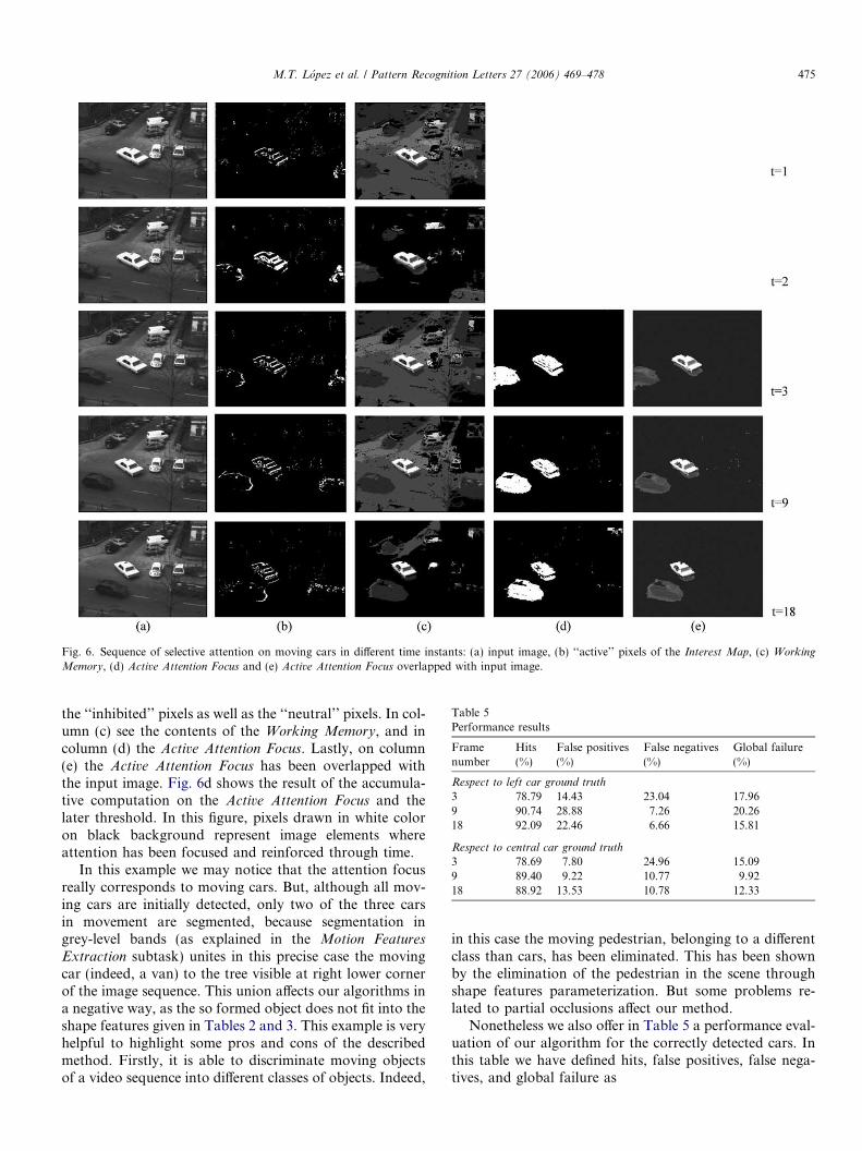
Fig. 6. Sequence of selective attention on moving cars in different time instants: (a) input image, (b) ‘‘active’’ pixels of the Interest Map, (c) Working
Memory, (d) Active Attention Focus and (e) Active Attention Focus overlapped with input image.
Table 5Performance results
Framenumber
Hits(%)
False positives(%)
False negatives(%)
Global failure(%)
Respect to left car ground truth
3 78.79 14.43 23.04 17.969 90.74 28.88 7.26 20.2618 92.09 22.46 6.66 15.81
Respect to central car ground truth
3 78.69 7.80 24.96 15.099 89.40 9.22 10.77 9.9218 88.92 13.53 10.78 12.33
M.T. Lopez et al. / Pattern Recognition Letters 27 (2006) 469–478 475
the ‘‘inhibited’’ pixels as well as the ‘‘neutral’’ pixels. In col-umn (c) see the contents of the Working Memory, and incolumn (d) the Active Attention Focus. Lastly, on column(e) the Active Attention Focus has been overlapped withthe input image. Fig. 6d shows the result of the accumula-tive computation on the Active Attention Focus and thelater threshold. In this figure, pixels drawn in white coloron black background represent image elements whereattention has been focused and reinforced through time.
In this example we may notice that the attention focusreally corresponds to moving cars. But, although all mov-ing cars are initially detected, only two of the three carsin movement are segmented, because segmentation ingrey-level bands (as explained in the Motion Features
Extraction subtask) unites in this precise case the movingcar (indeed, a van) to the tree visible at right lower cornerof the image sequence. This union affects our algorithms ina negative way, as the so formed object does not fit into theshape features given in Tables 2 and 3. This example is veryhelpful to highlight some pros and cons of the describedmethod. Firstly, it is able to discriminate moving objectsof a video sequence into different classes of objects. Indeed,
in this case the moving pedestrian, belonging to a differentclass than cars, has been eliminated. This has been shownby the elimination of the pedestrian in the scene throughshape features parameterization. But some problems re-lated to partial occlusions affect our method.
Nonetheless we also offer in Table 5 a performance eval-uation of our algorithm for the correctly detected cars. Inthis table we have defined hits, false positives, false nega-tives, and global failure as
hits ¼ pixels that belong to the attention focus and to the ground truth
number of pixels of the ground truth� 100
false positives ¼ pixels that belong to the attention focus; but not to the ground truth
number of pixels of the attention focus� 100
false negatives ¼ pixels that belong to the ground truth; but not to the attention focus
number of pixels of the ground truth� 100
global failure ¼ false negativesþ false positivesnumber of pixels of the ground truthþ number of pixels of the attention focus
� 100
Table 6Spot Shape Features used in Working Memory
Parameter Value (number of pixels)
Spot maximum size 4000Spot maximum width 100Spot maximum height 100
Table 7Object Shape Features used in Active Attention Focus
Parameter Value (in pixels) Value (ratios)
Object size range 200–4000Object width range 10–100Object height range 10–100Object width–height ratio range 0.10–2.00Object compactness range 0.40–1.00
Table 8Parameters of the Attention Map
Parameter Values
Charge constant: CAM 200Discharge constant: DAM 205Threshold: h 205
476 M.T. Lopez et al. / Pattern Recognition Letters 27 (2006) 469–478
When looking at the results table (Table 5), we may ob-serve that the highest value for false negatives is got atframe number 3. This is the first frame where it is possibleto get elements in the Attention Focus, according to ouralgorithms with values provided at Table 4. From that mo-ment on, you may note how the percentage of false nega-tives drops rapidly. It is also important to highlight thatthe percentage of false positives is substantially lower forthe central car than for the taxi, whilst false negatives arehigher for the taxi than for the central car.
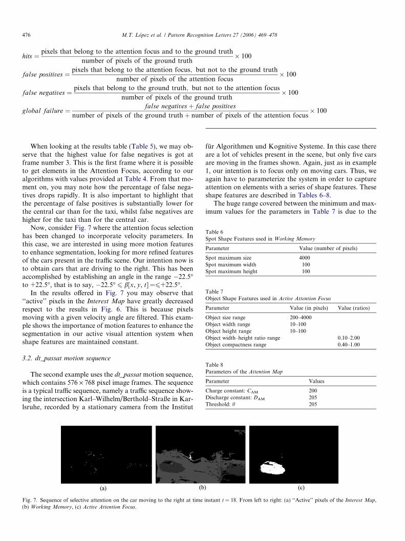
Now, consider Fig. 7 where the attention focus selectionhas been changed to incorporate velocity parameters. Inthis case, we are interested in using more motion featuresto enhance segmentation, looking for more refined featuresof the cars present in the traffic scene. Our intention now isto obtain cars that are driving to the right. This has beenaccomplished by establishing an angle in the range �22.5�to +22.5�, that is to say, �22.5� 6 b[x, y, t] =6+22.5�.
In the results offered in Fig. 7 you may observe that‘‘active’’ pixels in the Interest Map have greatly decreasedrespect to the results in Fig. 6. This is because pixelsmoving with a given velocity angle are filtered. This exam-ple shows the importance of motion features to enhance thesegmentation in our active visual attention system whenshape features are maintained constant.
3.2. dt_passat motion sequence
The second example uses the dt_passatmotion sequence,which contains 576 · 768 pixel image frames. The sequenceis a typical traffic sequence, namely a traffic sequence show-ing the intersection Karl–Wilhelm/Berthold–Straße in Kar-lsruhe, recorded by a stationary camera from the Institut
Fig. 7. Sequence of selective attention on the car moving to the right at time(b) Working Memory, (c) Active Attention Focus.
fur Algorithmen und Kognitive Systeme. In this case thereare a lot of vehicles present in the scene, but only five carsare moving in the frames shown. Again, just as in example1, our intention is to focus only on moving cars. Thus, weagain have to parameterize the system in order to captureattention on elements with a series of shape features. Theseshape features are described in Tables 6–8.
The huge range covered between the minimum and max-imum values for the parameters in Table 7 is due to the
instant t = 18. From left to right: (a) ‘‘Active’’ pixels of the Interest Map,
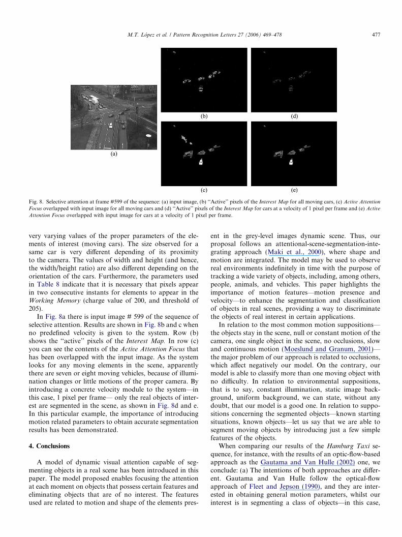
Fig. 8. Selective attention at frame #599 of the sequence: (a) input image, (b) ‘‘Active’’ pixels of the Interest Map for all moving cars, (c) Active AttentionFocus overlapped with input image for all moving cars and (d) ‘‘Active’’ pixels of the Interest Map for cars at a velocity of 1 pixel per frame and (e) ActiveAttention Focus overlapped with input image for cars at a velocity of 1 pixel per frame.
M.T. Lopez et al. / Pattern Recognition Letters 27 (2006) 469–478 477
very varying values of the proper parameters of the ele-ments of interest (moving cars). The size observed for asame car is very different depending of its proximityto the camera. The values of width and height (and hence,the width/height ratio) are also different depending on theorientation of the cars. Furthermore, the parameters usedin Table 8 indicate that it is necessary that pixels appearin two consecutive instants for elements to appear in theWorking Memory (charge value of 200, and threshold of205).
In Fig. 8a there is input image # 599 of the sequence ofselective attention. Results are shown in Fig. 8b and c whenno predefined velocity is given to the system. Row (b)shows the ‘‘active’’ pixels of the Interest Map. In row (c)you can see the contents of the Active Attention Focus thathas been overlapped with the input image. As the systemlooks for any moving elements in the scene, apparentlythere are seven or eight moving vehicles, because of illumi-nation changes or little motions of the proper camera. Byintroducing a concrete velocity module to the system—inthis case, 1 pixel per frame— only the real objects of inter-est are segmented in the scene, as shown in Fig. 8d and e.In this particular example, the importance of introducingmotion related parameters to obtain accurate segmentationresults has been demonstrated.
4. Conclusions
A model of dynamic visual attention capable of seg-menting objects in a real scene has been introduced in thispaper. The model proposed enables focusing the attentionat each moment on objects that possess certain features andeliminating objects that are of no interest. The featuresused are related to motion and shape of the elements pres-
ent in the grey-level images dynamic scene. Thus, ourproposal follows an attentional-scene-segmentation-inte-grating approach (Maki et al., 2000), where shape andmotion are integrated. The model may be used to observereal environments indefinitely in time with the purpose oftracking a wide variety of objects, including, among others,people, animals, and vehicles. This paper highlights theimportance of motion features—motion presence andvelocity—to enhance the segmentation and classificationof objects in real scenes, providing a way to discriminatethe objects of real interest in certain applications.
In relation to the most common motion suppositions—the objects stay in the scene, null or constant motion of thecamera, one single object in the scene, no occlusions, slowand continuous motion (Moeslund and Granum, 2001)—the major problem of our approach is related to occlusions,which affect negatively our model. On the contrary, ourmodel is able to classify more than one moving object withno difficulty. In relation to environmental suppositions,that is to say, constant illumination, static image back-ground, uniform background, we can state, without anydoubt, that our model is a good one. In relation to suppo-sitions concerning the segmented objects—known startingsituations, known objects—let us say that we are able tosegment moving objects by introducing just a few simplefeatures of the objects.
When comparing our results of the Hamburg Taxi se-quence, for instance, with the results of an optic-flow-basedapproach as the Gautama and Van Hulle (2002) one, weconclude: (a) The intentions of both approaches are differ-ent. Gautama and Van Hulle follow the optical-flowapproach of Fleet and Jepson (1990), and they are inter-ested in obtaining general motion parameters, whilst ourinterest is in segmenting a class of objects—in this case,
478 M.T. Lopez et al. / Pattern Recognition Letters 27 (2006) 469–478
we are only interested in cars. That is why our method doesnot obtain the pedestrian as Gautama and Van Hulle do.(b) Gautama and Van Hulle have to label the objectsmanually after the calculus of direction, speed and spatiallocation. Our algorithm labels automatically the objectssegmented as an important part of visual attention method-ology. (c) Our algorithm has problems with occlusions,whilst the optical-flow approach (whose interest is not inlabeling objects) apparently does not suffer this limitationin the Hamburg Taxi sequence.
In relation to probabilistic approaches to motion group-ing and segmentation, e.g. (Robles-Kelly and Hancock,2004), and also comparing the results with the Hamburg
Taxi sequence, we observe that again our algorithm losesone car due to the imposed shape size criteria (leading tothe union of the tree with the car). Following the terminol-ogy of Robles–Kelly and Hancock, our algorithm does notdetect one of the three clusters. Nevertheless, when com-paring the result of Active Attention Focus overlapped withinput image of our approach with the final result ofRobles–Kelly and Hancock�s probabilistic grouping andsegmentation method in relation to ground truth, oursegmented objects are much closer to the ground truth,as it may be noticed having a quick look.
Summing it up, the main contribution in our approachis the incorporation of the ‘‘motion presence’’, ‘‘angle ofthe velocity’’ and ‘‘module of the velocity’’ motion featuresat pixel level. The last two features are rarely used in objectsegmentation and tracking (Fennema and Thompson,1979), but have proven to be good discriminants in theexamples offered in this paper. Indeed, a couple of exam-ples have been offered where, by incrementing the numberof motion features, whilst maintaining the shape featuresconstant, the attention focus is enhanced.
Acknowledgements
This work is partially supported by the Spanish CICYTTIN2004-07661-C02-01 and TIN2004-07661-C02-02grants. The authors are thankful to the anonymous review-ers for their very helpful comments.
References
Chella, A., Frixione, M., Gaglio, S., 2000. Understanding dynamic scenes.Artificial Intell. 123 (1–2), 89–132.
Fennema, C.L., Thompson, W.B., 1979. Velocity determination in scenescontaining several moving objects. Comput. Graphics Image Process.9, 301–315.
Fernandez, M.A., Fernandez-Caballero, A., Lopez, M.T., Mira, J., 2003.Length-speed ratio (LSR) as a characteristic for moving elements real-time classification. Real-Time Imaging 9, 49–59.
Fernandez-Caballero, A., Fernandez, M.A., Mira, J., Delgado, A.E.,2003. Spatio-temporal shape building from image sequences usinglateral interaction in accumulative computation. Pattern Recognition36 (5), 1131–1142.
Fernandez, M.A., Mira, J., Lopez, M.T., Alvarez, J.R., Manjarres, A.,Barro, S., 1995. Local accumulation of persistent activity at synapticlevel: application to motion analysis. From Natural to ArtificialNeural Computation. Springer-Verlag, pp. 137–143.
Fernandez-Caballero, A., Mira, J., Fernandez, M.A., Lopez, M.T., 2001.Segmentation from motion of non-rigid objects by neuronal lateralinteraction. Pattern Recognition Lett. 22 (14), 1517–1524.
Fleet, D.J., Jepson, A.D., 1990. Computation of component imagevelocity from local phase information. Internat. J. Comput. Vision 5(1), 77–104.
Gautama, T., Van Hulle, M.M., 2002. A phase-based approach to theestimation of the optical flow field using spatial filtering. IEEE Trans.Neural Networks 13 (5), 1127–1136.
Lopez, M.T., Fernandez, M.A., Fernandez-Caballero, A., Delgado, A.E.,2003. Neurally inspired mechanisms for the dynamic visual attentionmap generation task. Computational Methods in Modeling Compu-tation. Springer-Verlag, pp. 694–701.
Maki, A., Nordlund, P., Eklundh, J.-O., 2000. Attentional scene segmen-tation: integrating depth and motion. Comput. Vision Image Under-standing 78 (3), 351–373.
Mira, J., Delgado, A.E., Fernandez-Caballero, A., Fernandez, M.A.,2004. Knowledge modelling for the motion detection task: thealgorithmic lateral inhibition method. Expert Systems with Appl. 27(2), 169–185.
Moeslund, T.B., Granum, E., 2001. A survey of computer vision-basedhuman motion capture. Comput. Vision Image Understanding 81,231–268.
Robles-Kelly, A., Hancock, E.R., 2004. A probabilistic spectral frame-work for grouping and segmentation. Pattern Recognition 37 (7),1387–1405.
Wu, L., Benois-Pineau, J., Delagnes, P., Barba, D., 1996. Spatio-temporalsegmentation of image sequences for object-oriented low bit-rate imagecoding. Signal Process.: Image Comm. 8 (6), 513–543.
Zaki, M., El Nahas, M.Y., Youssef, M., 2004. EMBOT: an enhancedmotion-based object tracker. J. Systems Software 69 (1–2), 149–158.