Dynamic infrared scene projection technologies under the ...
13
Dynamic infrared scene projection technologies under the microscope Owen M. Williams Weapons Systems Division, Defence Science and Technology Organisation P0 Box 1500, Salisbury, South Australia 5108 ABSTRACT Over the past five years there has been steady development in the field of dynamic infrared scene generation (DIRSP), to the point where the first generation of dynamic infrared scene projectors can now be subjected to critical analysis. In this paper, the specific areas of optical projection validity, spectral emissivity and temperature resolution are discussed relation to the viability of the DIRSP systems to which they apply. Keywords: dynamic infrared scene projection, spectral emissivity, temperature resolution 1. INTRODUCTION The development of dynamic infrared scene projection (DIRSP) technology has reached the point where it is expected that a market for infrared projectors will develop over the next few years. At the same time as the technologies have been developing there has been a concerted effort to develop in parallel an analytical framework for comparing and contrasting the competing technologies.''2 It is expected in future that this will form the basis for development of a formal procedure for characterization of dynamic infrared scene projectors. At the present time there is still a need for critical insights into the DIRSP technologies currently being developed. In particular, it is necessary to add to the existing list of those areas likely to determine the viability or otherwise of specific DHtSP systems. This defines the theme of the present paper. Three specific operational areas are investigated: optical projection validity, spectral emissivity and temperature reso- lution. The significance of each of these areas is discussed in relation to the viability of the DIRSP systems to which they apply. . 2. OPTICAL PROJECTION VALIDITY The fundamental objective underlying the development of a dynamic infrared scene projection capability is to ensure that the projected scene characteristics match as closely as possible to those defining the real-world scene being simulated — radiometrically, spectrally, spatially and temporally. In order to investigate the optical design implications arising from this objective we refer to the projector/imaging unit-under-test (UUT) optical system shown in Figure 1. Note that both the projector and UUT optical systems are represented generically. The exact nature (reflective or refractive) is immaterial, as is the method by which the UUT image is read; for example, the scene irradiance imaged at the focal plane may be raster scanned (as is common practice in many contemporary thermal imager designs) or may be read by an infrared focal plane array backed by a charge-coupled device. The assessment of optical projection validity is associated with the ease with which it is possible to identify an object plane from which radiation spreads to fill the aperture of the projector collimating lens. In most cases (e.g., emissive projectors,'3'8 the infrared liquid crystal light valve'9), the object plane is easily located at the pixelated active device position. In these cases, the collected radiation may be regarded as sufficiently Lambertian in character that when it is collimated it will uniformly irradiate the UUT entrance aperture. The optical processing by the UUT objective lens will then be the same as that occurring in real-world applications. Uniform irradiation of the UUT entrance aperture thus defines the fundamental condition for optical projection validity. 2 ISPIE Vol. 2469 O-8194-1822-6/95/$6.OO Downloaded From: http://proceedings.spiedigitallibrary.org/ on 02/18/2016 Terms of Use: http://spiedigitallibrary.org/ss/TermsOfUse.aspx
-
Upload
khangminh22 -
Category
Documents
-
view
6 -
download
0
Transcript of Dynamic infrared scene projection technologies under the ...
Dynamic infrared scene projection technologiesunder the microscope
Owen M. Williams
Weapons Systems Division, Defence Science and Technology OrganisationP0 Box 1500, Salisbury, South Australia 5108
ABSTRACT
Over the past five years there has been steady development in the field of dynamic infrared scene generation (DIRSP),to the point where the first generation of dynamic infrared scene projectors can now be subjected to critical analysis. Inthis paper, the specific areas of optical projection validity, spectral emissivity and temperature resolution are discussedrelation to the viability of the DIRSP systems to which they apply.
Keywords: dynamic infrared scene projection, spectral emissivity, temperature resolution
1. INTRODUCTION
The development of dynamic infrared scene projection (DIRSP) technology has reached the point where it is expectedthat a market for infrared projectors will develop over the next few years. At the same time as the technologies havebeen developing there has been a concerted effort to develop in parallel an analytical framework for comparing andcontrasting the competing technologies.''2 It is expected in future that this will form the basis for development of aformal procedure for characterization of dynamic infrared scene projectors.
At the present time there is still a need for critical insights into the DIRSP technologies currently being developed.In particular, it is necessary to add to the existing list of those areas likely to determine the viability or otherwise ofspecific DHtSP systems. This defines the theme of the present paper.
Three specific operational areas are investigated: optical projection validity, spectral emissivity and temperature reso-lution. The significance of each of these areas is discussed in relation to the viability of the DIRSP systems to whichthey apply.
.
2. OPTICAL PROJECTION VALIDITY
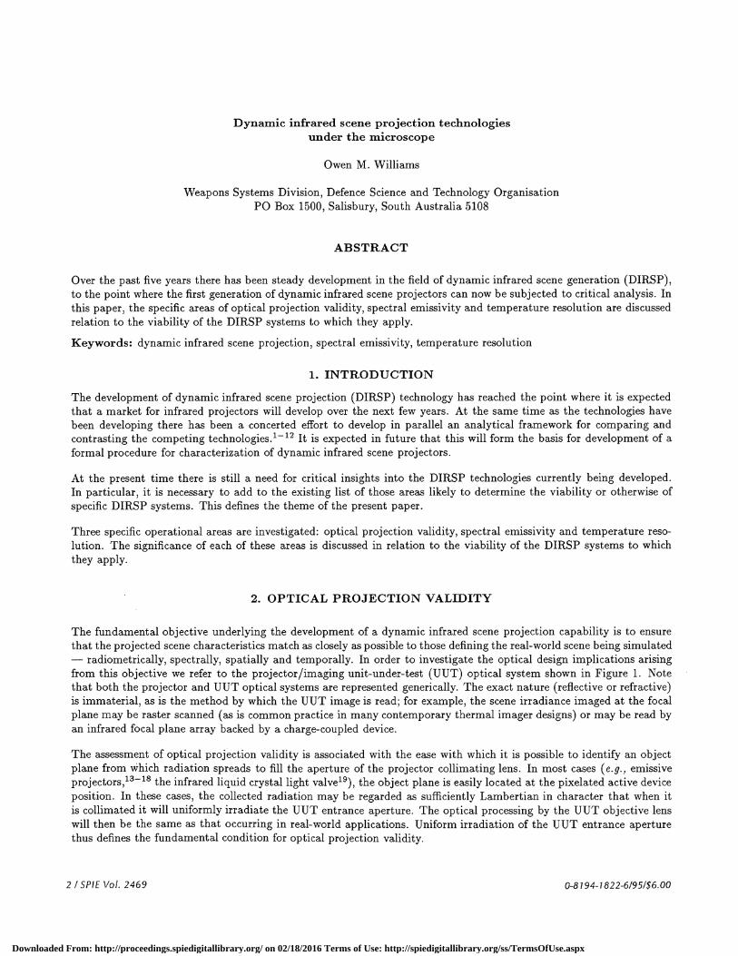
The fundamental objective underlying the development of a dynamic infrared scene projection capability is to ensurethat the projected scene characteristics match as closely as possible to those defining the real-world scene being simulated— radiometrically, spectrally, spatially and temporally. In order to investigate the optical design implications arisingfrom this objective we refer to the projector/imaging unit-under-test (UUT) optical system shown in Figure 1. Notethat both the projector and UUT optical systems are represented generically. The exact nature (reflective or refractive)is immaterial, as is the method by which the UUT image is read; for example, the scene irradiance imaged at the focalplane may be raster scanned (as is common practice in many contemporary thermal imager designs) or may be read byan infrared focal plane array backed by a charge-coupled device.
The assessment of optical projection validity is associated with the ease with which it is possible to identify an objectplane from which radiation spreads to fill the aperture of the projector collimating lens. In most cases (e.g.,emissiveprojectors,'3'8 the infrared liquid crystal light valve'9), the object plane is easily located at the pixelated active deviceposition. In these cases, the collected radiation may be regarded as sufficiently Lambertian in character that when itis collimated it will uniformly irradiate the UUT entrance aperture. The optical processing by the UUT objective lenswill then be the same as that occurring in real-world applications. Uniform irradiation of the UUT entrance aperturethus defines the fundamental condition for optical projection validity.
2 ISPIE Vol. 2469 O-8194-1822-6/95/$6.OO
Downloaded From: http://proceedings.spiedigitallibrary.org/ on 02/18/2016 Terms of Use: http://spiedigitallibrary.org/ss/TermsOfUse.aspx
Infrared
Scene
Radiance
UUTlens
UUT7 imageplane
Imaging UUT
(a) Real-world operation
Coffimating
ojectorobjectplane
Projector
(b) Simulation
UUTlens
UUT7 imageplane
imaging UUT
Figure 1 Comparison between real-world and simulation optical systems
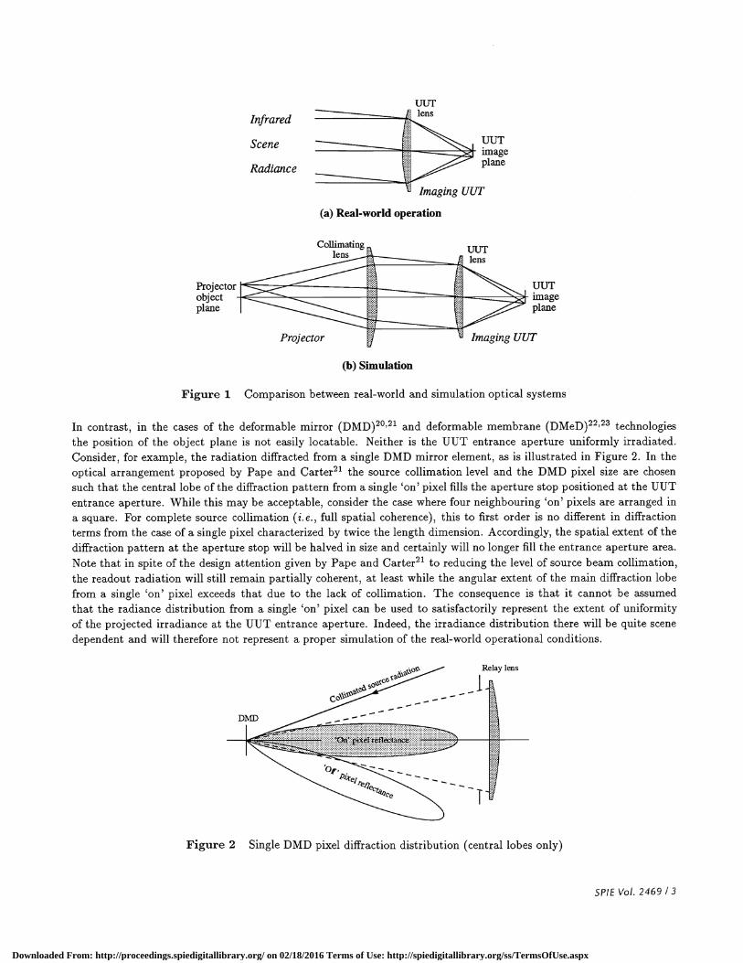
In contrast, in the cases of the deformable mirror (DMD)20'2' and deformable membrane (DMeD)22'23 technologiesthe position of the object plane is not easily locatable. Neither is the UUT entrance aperture uniformly irradiated.Consider, for example, the radiation diffracted from a single DMD mirror element, as is illustrated in Figure 2. In theoptical arrangement proposed by Pape and Carter2' the source collimation level and the DMD pixel size are chosensuch that the central lobe of the diffraction pattern from a single 'on' pixel fills the aperture stop positioned at the UUTentrance aperture. While this may be acceptable, consider the case where four neighbouring 'on' pixels are arranged ina square. For complete source collimation (i.e., full spatial coherence), this to first order is no different in diffractionterms from the case of a single pixel characterized by twice the length dimension. Accordingly, the spatial extent of thediffraction pattern at the aperture stop will be halved in size and certainly will no longer fill the entrance aperture area.Note that in spite of the design attention given by Pape and Carter2' to reducing the level of source beam collimation,the readout radiation will still remain partially coherent, at least while the angular extent of the main diffraction lobefrom a single 'on' pixel exceeds that due to the lack of collimation. The consequence is that it cannot be assumedthat the radiance distribution from a single 'on' pixel can be used to satisfactorily represent the extent of uniformityof the projected irradiance at the UUT entrance aperture. Indeed, the irradiance distribution there will be quite scenedependent and will therefore not represent a proper simulation of the real-world operational conditions.
Relay lens
Figure 2 Single DMD pixel diffraction distribution (central lobes only)
SPIE Vol. 2469 I 3
DMD
Downloaded From: http://proceedings.spiedigitallibrary.org/ on 02/18/2016 Terms of Use: http://spiedigitallibrary.org/ss/TermsOfUse.aspx
Similar concerns may be voiced concerning the deformable membrane22'23 device and phase modulated DMD2° pro-jection technologies. In neither case has an optical system been proposed that satisfies the condition that the UUTentrance aperture should be uniformly filled with projected radiance. Indeed, in essence, the optical systems representcoherent optical processors. The radiation pattern at the UUT entrance aperture is therefore neither uniform nor inco-herent, both of which are essential characteristics for proper simulation of real-world conditions. Without due opticaldesign care (particularly where the UUT includes a Cassegrain focusing system4), the image irradiance at the UUTfocal plane may be quite different from that which it is intended to simulate.
In spite of the absence of definitive analysis, it can be stated that all of the deformable mirror or membrane systemsare characterized by the same problem; namely, that it is not possible (at least, not without the benefit of a complexoptical system) to utilize reflective arrays for simultaneously fulfilling the two most important optical roles: namely, forensuring that the output radiance is spatially modulated in the required scene pattern, and for spreading the radianceemitted from each pixel site in such a way that it uniformly fills the UUT entrance aperture. The fundamental problemassociated with any of the deformable mirror or membrane array systems is therefore one of valid optical system design.
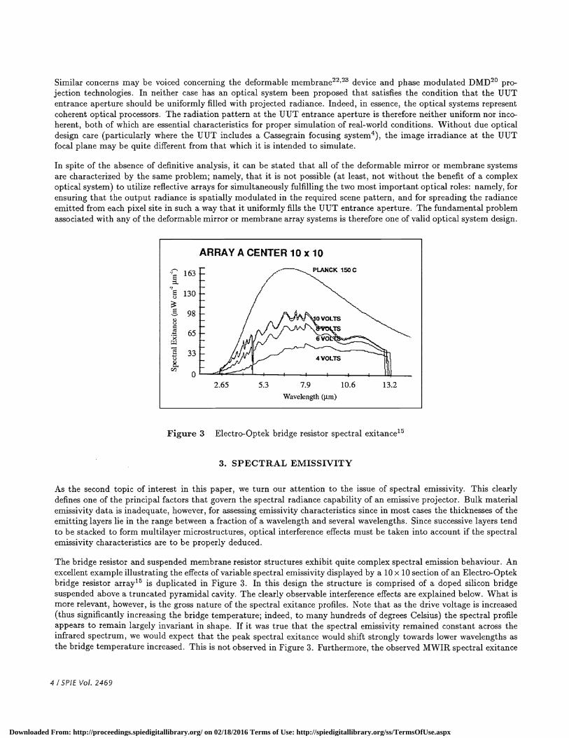
Figure 3 Electro-Optek bridge resistor spectral exitance15
3. SPECTRAL EMISSIVITY
As the second topic of interest in this paper, we turn our attention to the issue of spectral emissivity. This clearlydefines one of the principal factors that govern the spectral radiance capability of an emissive projector. Bulk materialemissivity data is inadequate, however, for assessing emissivity characteristics since in most cases the thicknesses of theemitting layers lie in the range between a fraction of a wavelength and several wavelengths. Since successive layers tendto be stacked to form multilayer microstructures, optical interference effects must be taken into account if the spectralemissivity characteristics are to be properly deduced.
The bridge resistor and suspended membrane resistor structures exhibit quite complex spectral emission behaviour. Anexcellent example illustrating the effects of variable spectral emissivity displayed by a 10 x 10 section of an Electro-Optekbridge resistor array'5 is duplicated in Figure 3. In this design the structure is comprised of a doped silicon bridgesuspended above a truncated pyramidal cavity. The clearly observable interference effects are explained below. What ismore relevant, however, is the gross nature of the spectral exitance profiles. Note that as the drive voltage is increased(thus significantly increasing the bridge temperature; indeed, to many hundreds of degrees Celsius) the spectral profileappears to remain largely invariant in shape. If it was true that the spectral emissivity remained constant across theinfrared spectrum, we would expect that the peak spectral exitance would shift strongly towards lower wavelengths asthe bridge temperature increased. This is not observed in Figure 3. Furthermore, the observed MWIR spectral exitance
4 I SPIE Vol. 2469
ARRAY A CENTER 10 x 10
163
98
E
130
E
C)
65
33
02.65 5.3 7.9 10.6 13.2
Wavelength (jim)
Downloaded From: http://proceedings.spiedigitallibrary.org/ on 02/18/2016 Terms of Use: http://spiedigitallibrary.org/ss/TermsOfUse.aspx
at high surface temperatures would be expected to be significantly greater than that from a 150°C blackbody. Again,this is not observed.
These observations can only be interpreted as indicating that the emissivity of doped silicon is spectrally dependent and,in particular, is small within the MWIR spectral region. This conclusion is consistent with the fact that at ambienttemperatures the MWIR transmission through silicon is high (and hence the MWIR emissivity is low) while in theLWIR region of the spectrum silicon is partially transparent (and hence the LWIR emissivity is moderate).24
In the absence of knowledge of the actual bridge temperature it is not possible to extract quantitative spectral emissivitydata from the profiles seen in Figure 3. It is possible, however, to make the observation that the MWIR emissivity ofthe doped silicon bridge used in the Electro-Optek devices is significantly smaller than the LWIR emissivity.
Similar arguments made be applied for assessing the emission characteristics of the structurally similar Optical E.T.C.bridge resistor16 . This is comprised of a polysilicon resistor sandwiched between thermal and contact vapor depositedlayers of silicon dioxide. It is well known24 that silicon dioxide is transmissive in the visible and infrared regions of thespectrum below ) = 4 jim and is largely opaque (and hence emissive) at higher wavelengths. This is consistent withthe observation that when an Optical E.T.C. resistor is heated to incandescence the visible glow is largely confined tothe resistive element (refer to Figure 3 of reference 15) ; that is, it does not appear to spread uniformly across the entirebridge structure in spite of the strong lateral heat conduction mechanism that occurs. Given the above comments onthe spectral emissivity of silicon dioxide, similar low emission rates would be expected across the SWIR and the MWIRregions of the spectrum, stretching at least up to the ) =4 jim transition region. Indeed, only at higher wavelengthswould the entire bridge structure be expected to radiate at high emissivity.
Although spectral emission data from the Optical E.T.C. devices has not been published, it can be concluded fromthe above discussion and by comparison with the optically similar Electro-Optek devices that the MWIR emissivity isexpected to be small while the LWIR emissivity is likely to be satisfactory. In the absence of measured spectral dataand/or detailed optical calculations it is not possible, however, to make a more definitive statement.
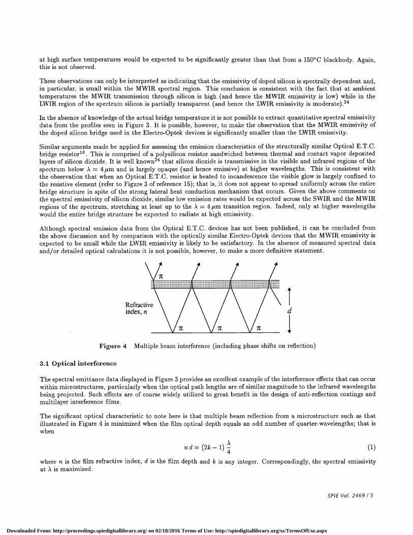
Figure 4 Multiple beam interference (including phase shifts on reflection)
3.1 Optical interference
The spectral emittance data displayed in Figure 3 provides an excellent example of the interference effects that can occurwithin microstructures, particularly when the optical path lengths are of similar magnitude to the infrared wavelengthsbeing projected. Such effects are of course widely utilized to great benefit in the design of anti-reflection coatings andmultilayer interference films.
The significant optical characteristic to note here is that multiple beam reflection from a microstructure such as thatillustrated in Figure 4 is minimized when the film optical depth equals an odd number of quarter-wavelengths; that iswhen
nd=(2k_1) (1)
where ri is the film refractive index, d is the film depth and k is any integer. Correspondingly, the spectral emissivityat,\ is maximized.
SPIE Vol. 2469 / 5
Downloaded From: http://proceedings.spiedigitallibrary.org/ on 02/18/2016 Terms of Use: http://spiedigitallibrary.org/ss/TermsOfUse.aspx
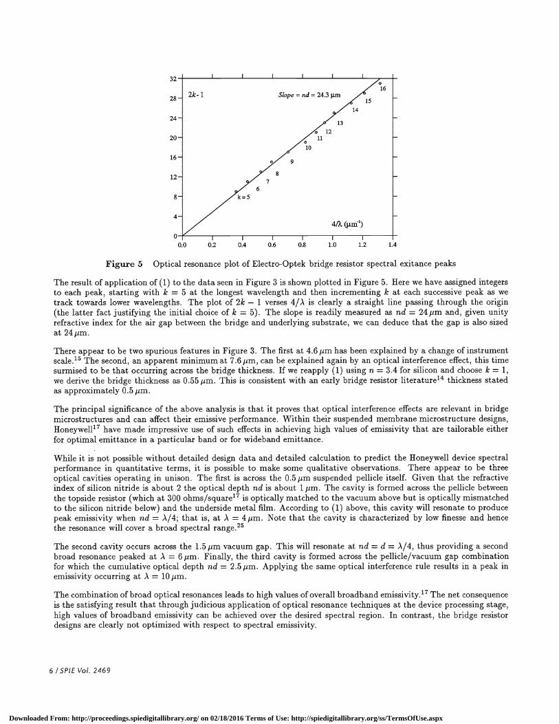
Figure 5 Optical resonance plot of Electro-Optek bridge resistor spectral exitance peaks
The result of application of (1) to the data seen in Figure 3 is shown plotted in Figure 5. Here we have assigned integersto each peak, starting with Ic = 5 at the longest wavelength and then incrementing Jr at each successive peak as wetrack towards lower wavelengths. The plot of 2k — 1 verses 4/A is clearly a straight line passing through the origin(the latter fact justifying the initial choice of k = 5). The slope is readily measured as nd = 24pm and, given unityrefractive index for the air gap between the bridge and underlying substrate, we can deduce that the gap is also sizedat 24 pm.
There appear to be two spurious features in Figure 3. The first at 4.6 pm has been explained by a change of instrumentscale.'5 The second, an apparent minimum at 7.6 pm, can be explained again by an optical interference effect, this timesurmised to be that occurring across the bridge thickness. If we reapply (1) using n = 3.4 for silicon and choose ic = 1,we derive the bridge thickness as 0.55 pm. This is consistent with an early bridge resistor literature'4 thickness statedas approximately 0.5 pm.
The principal significance of the above analysis is that it proves that optical interference effects are relevant in bridgemicrostructures and can affect their emissive performance. Within their suspended membrane microstructure designs,Honeywell'7 have made impressive use of such effects in achieving high values of emissivity that are tailorable eitherfor optimal emittance in a particular band or for wideband emittance.
While it is not possible without detailed design data and detailed calculation to predict the Honeywell device spectralperformance in quantitative terms, it is possible to make some qualitative observations. There appear to be threeoptical cavities operating in unison. The first is across the 0.5 pm suspended pellicle itself. Given that the refractiveindex of silicon nitride is about 2 the optical depth nd is about 1 pm. The cavity is formed across the pellicle betweenthe topside resistor (which at 300 ohms/square'7 is optically matched to the vacuum above but is optically mismatchedto the silicon nitride below) and the underside metal film. According to (1) above, this cavity will resonate to producepeak emissivity when nd = ,\/4; that is, at .\ = 4pm. Note that the cavity is characterized by low finesse and hencethe resonance will cover a broad spectral range.25
The second cavity occurs across the 1.5 pm vacuum gap. This will resonate at nd = d = .A/4, thus providing a secondbroad resonance peaked at A = 6pm. Finally, the third cavity is formed across the pellicle/vacuum gap combinationfor which the cumulative optical depth nd = 2.5pm. Applying the same optical interference rule results in a peak inemissivity occurring at ) = 10pm.
The combination of broad optical resonances leads to high values of overall broadband emissivity.'7 The net consequenceis the satisfying result that through judicious application of optical resonance techniques at the device processing stage,high values of broadband emissivity can be achieved over the desired spectral region. In contrast, the bridge resistordesigns are clearly not optimized with respect to spectral emissivity.
6 ISPIE Vol. 2469
0.0 0.2 0.4 0.6 0.8 1.0 1.2 1.4
Downloaded From: http://proceedings.spiedigitallibrary.org/ on 02/18/2016 Terms of Use: http://spiedigitallibrary.org/ss/TermsOfUse.aspx
c)
C
C)
AT= T- 7(°C)
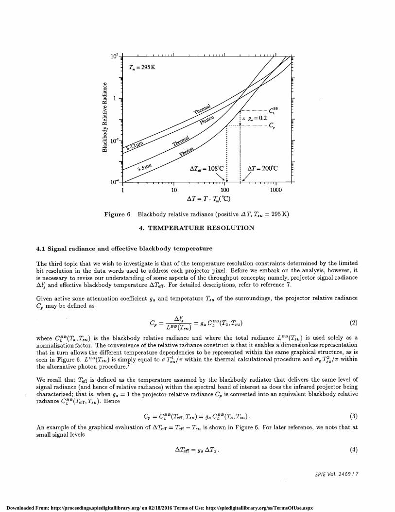
Figure 6 Blackbody relative radiance (positive L T, T8 = 295 K)
4. TEMPERATURE RESOLUTION
4.1 Signal radiance and effective blackbody temperature
The third topic that we wish to investigate is that of the temperature resolution constraints determined by the limitedbit resolution in the data words used to address each projector pixel. Before we embark on the analysis, however, itis necessary to revise our understanding of some aspects of the throughput concepts; namely, projector signal radiancei2l and effective blackbody temperature LTeff. For detailed descriptions, refer to reference 7.
Given active zone attenuation coefficient g and temperature T3 of the surroundings, the projector relative radiancecp may be defined as
C- - CBBITT 2p —LBB(TSU)
g i a,
where C(Ta , T8) 5 the blackbody relative radiance and where the total radiance LBB(TSU) is used solely as anormalization factor. The convenience of the relative radiance construct is that it enables a dimensionless representationthat in turn allows the different temperature dependencies to be represented within the same graphical structure, as isseen in Figure 6. LBB(T8) 5 simply equal to T/ir within the thermal calculational procedure and oq withinthe alternative photon
We recall that Teff 5 defined as the temperature assumed by the blackbody radiator that delivers the same level ofsignal radiance (and hence of relative radiance) within the spectral band of interest as does the infrared projector beingcharacterized; that is, when g = 1 the projector relative radiance C, is converted into an equivalent blackbody relativeradiance Cr(Teff,Tsu). Hence
c ciBB/rr ,-r \ ,iBB f m— L/L leff,1su) = ga-'L 1a,1suAn example of the graphical evaluation of Teff = Teff —T3 is shown in Figure 6. For later reference, we note that atsmall signal levels
L\TeffgaL1T. (4)
SPIE Vol. 2469 / 7
1 10 100 1000
Downloaded From: http://proceedings.spiedigitallibrary.org/ on 02/18/2016 Terms of Use: http://spiedigitallibrary.org/ss/TermsOfUse.aspx
The significance in the present context is associated with the nonlinear nature ofthe curves in Figure 6. Accordingly, wenow turn our attention to the consequences on both the temperature resolution and minimum simulated temperaturecapabilities.
4.2 Dynamic RangeDynamic range is a parameter used widely in the electronics field to specify the range over which a sensor or amplifiercan be controllably operated; that is, controlled in such a way that its output increases monotonically from a low toa maximum value as the input is increased. Within the general electronics field, dynamic range is defined as the ratioof the maximum output voltage or current to the minimum voltage or current that can be controllably generated.Although dynamic range is often expressed in decibels (dB), this convention will not be followed here.
The concept of dynamic range has been imported into the DIRSP field where, in particular, it has been used forspecifying the range of controllable output from those projectors that operate essentially in a spatial light modulatormode. The Hughes LCLV, the deformable mirror and membrane devices and the laser scanners are all included in thiscategory. For such cases, we can define dynamic range as the ratio of the maximum signal radiance to the minimumsignal radiance that can be controllably projected. We shall discuss the implications arising from this definition shortly.
Emissive projectors are different. There, it is the drive power that must be modulated in order to change the surfacetemperature and hence the value of effective blackbody temperature. In contrast, signal radiance is a highly nonlinearfunction of temperature, as can be seen from Figure 6. It therefore seems sensible in the emissive projector caseto instead advocate use of a definition of dynamic range based on temperature rather than signal. Accordingly, wedefine the dynamic range (temperature) as the ratio of the maximum simulated temperature difference to the minimumsimulated temperature difference that can be controllably projected.
The demands for high values of dynamic range in DIRSP applications can be quite large. For example, in applyingthe temperature definition, we find that for a projector required to operate over the wide simulated temperature range77 — 500K at 0.1 K temperature resolution, the dynamic range requirement is 4230 (or 12 bits). In the anticipatedfuture FUR and thermal imager test and evaluation roles, the demands can be even greater; for example, if operationover the range 240 —340 K at 10 mK resolution is required, then the dynamic range rises to 10000 (or 13 bits). It is clearin each of these examples that the demands on the multiplexer/addressing scheme electronics are high, particularlywhen large array projection is required.
4.3 Emissive projectors
Once the maximumsimulated temperature range has been specified or is otherwise limited, the primary goal in seeking alarge value of dynamic range is to increase the temperature resolution, particularly that close to ambient temperatureswhere it is necessary to validly simulate infrared emissions from natural and man-made features, backgrounds andclutter. We wish here to estimate the limitations on emissive projector simulated temperature resolution capability.
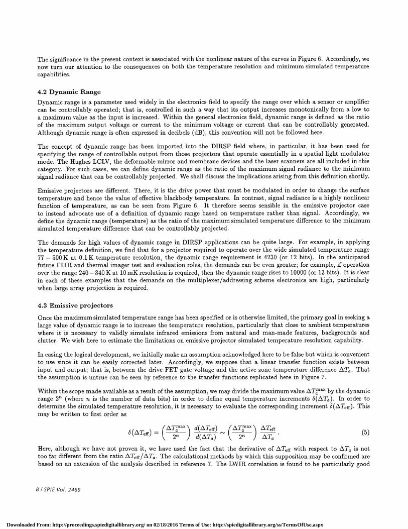
In easing the logical development, we initially make an assumption acknowledged here to be false but which is convenientto use since it can be easily corrected later. Accordingly, we suppose that a linear transfer function exists betweeninput and output; that is, between the drive FET gate voltage and the active zone temperature difference LTa. Thatthe assumption is untrue can be seen by reference to the transfer functions replicated here in Figure 7.
Within the scope made available as a result of the assumption, we may divide the maximum value zTx by the dynamicrange 2' (where n is the number of data bits) in order to define equal temperature increments 6(LTa). In order todetermine the simulated temperature resolution, it is necessary to evaluate the corresponding increment t5(LTeff). Thismay be written to first order as
(TaX\ d(Teff) LTeff6(Teff) 2 ) d(Ta) 2 ) Ta (5)
Here, although we have not proven it, we have used the fact that the derivative of LTeff with respect to /XTa is nottoo far different from the ratio LTeff/Ta. The calculational methods by which this supposition may be confirmed arebased on an extension of the analysis described in reference 7. The LWIR correlation is found to be particularly good
8 ISP/F Vol. 2469
Downloaded From: http://proceedings.spiedigitallibrary.org/ on 02/18/2016 Terms of Use: http://spiedigitallibrary.org/ss/TermsOfUse.aspx
1.o• (b) IIa (a) O.8 . ;•
R=l5Kohm y'__• I1 UiI UI zE4 1 <.-.- I 0a I12 / 0.4 :7 z
I A' <B.Ae thinflim c.
( , — wO.2 /3 10 15 29
Vrofresh (V) Optron DMeD
ic;o 150 200MEMBRANE BIAS (VOLTS)
Figure 7 British Aerospace thin film resistor13 and Optron Systems DMeD22 input transfer functions
over the full range of values of both iTa and the active zone attenuation coefficient g . The MWIIt correlation is alsogood except in the region of the knee on low g curves7 where the derivative can be up to 50-100% greater than thevalue defined by the ratio. Within the present context, this is judged to be acceptable.
Now, under small signal conditions eqn (4) holds and therefore the above approximation reduces to
c5(LTeff) 2 (6)
Indeed, this result is also largely true at higher values of LiTa , as can be confirmed by calculated examples.
If the assumption of linearity of the drive FET transfer function were true, the principal conclusion that could be drawnfrom (6) would be that the temperature resolution may be divided into equal increments over the entire dynamic range.However, we know that the assumption is false. As seen from Figure 7, the transfer function is more parabolic in shape,reflecting the fact that the drive power is proportional to the square of the drive current. In correcting the assumption,then, we find that at low values of Teff the increments 6(LTeff) are smaller than those at large LTeff.
The net result is that emissive projector temperature resolution will be best at low simulated temperatures. Thisfortuitously matches the requirements. At low Teff, there is a need for high resolution in order to provide finediscrimination amongst infrared scene features near to ambient temperature. At higher temperatures the need is not sogreat. There, automatic gain control (AGC) functions are often activated within front-end thermal imager and FLIRelectronics when high levels of signal irradiance characteristic of hot targets are encountered. Radiometric precision isthereby destroyed. The consequence is that there is little need for fine temperature resolution at the high end of thesimulated temperature range. In the emissive projector case, then, fine temperature resolution is available where it isrequired.
4.4 Spatial light modulators and laser scanners
Spatial light modulators and laser scanners differ in modus operandi in that it is signal radiance rather than simulatedtemperature that is modulated. It is here that we encounter some difficulty arising from the significantly nonlineardependence of effective blackbody temperature on signal radiance.
It is important here to stress the pre-eminent role that effective blackbody temperature plays within the imaging infraredfield. Indeed, it defines the premier measure that characterizes target brightness. It could be argued on radiometricgrounds that this is not the case and that signal radiance should instead be preferred. That may be so. However, it isa fact that it is temperature and not signal radiance that is the commonly quoted brightness quantity. For example, inthe ambient temperature thermal imaging region the commonly quoted parameters are temperature difference, noiseequivalent temperature difference and minimum resolvable temperature difference.
SPIE Vol. 2469 / 9
Downloaded From: http://proceedings.spiedigitallibrary.org/ on 02/18/2016 Terms of Use: http://spiedigitallibrary.org/ss/TermsOfUse.aspx
100
L)
.100'1)
11E2
0.1
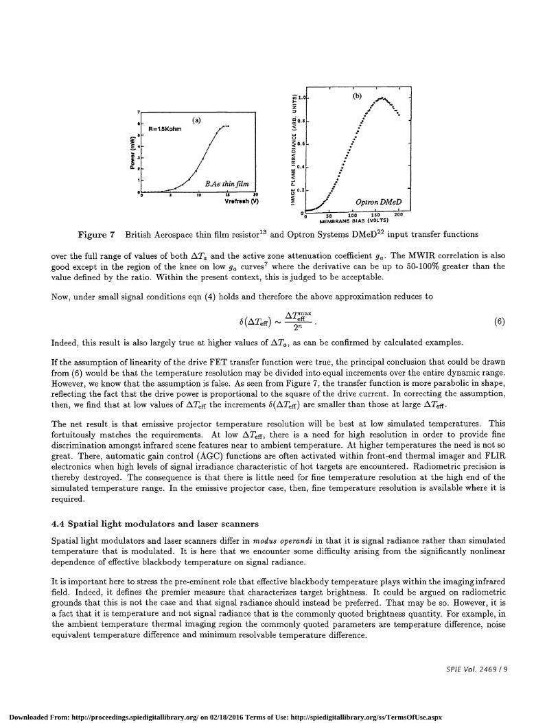
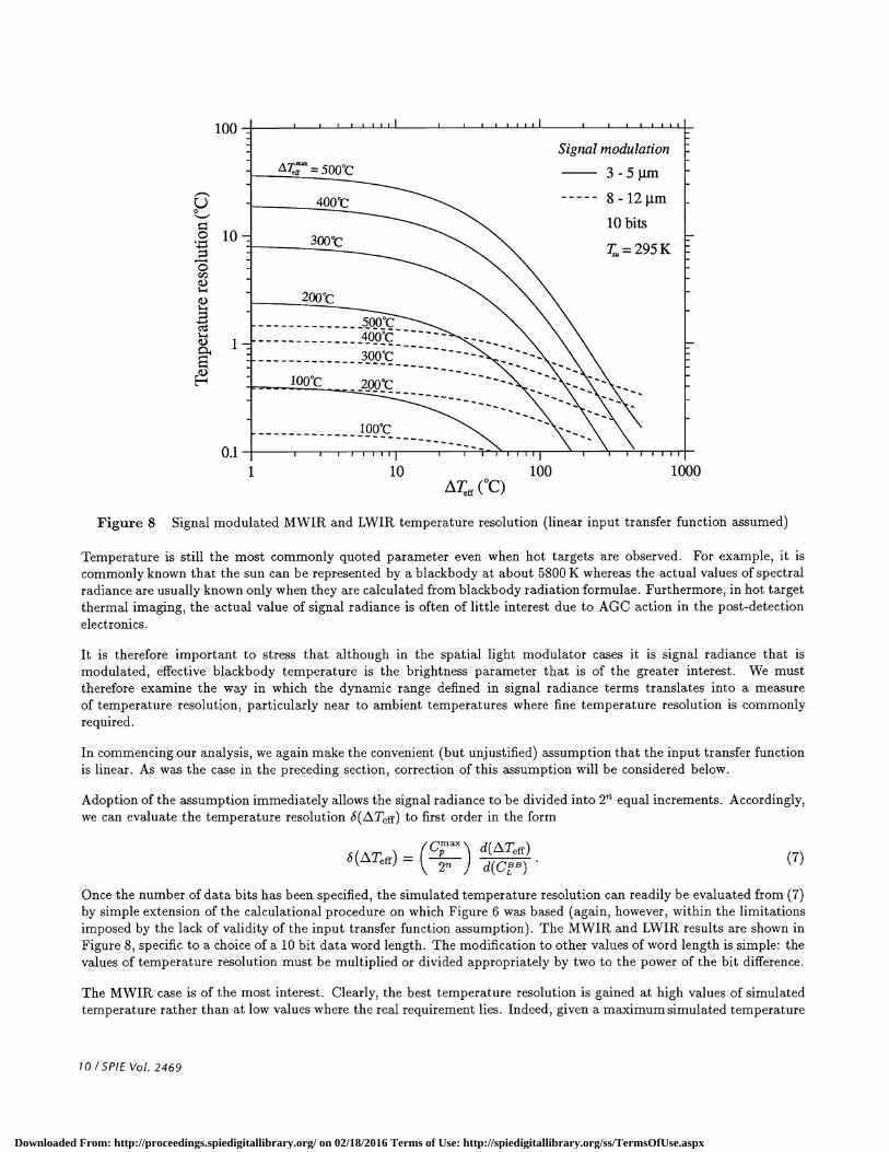
Figure 8 Signal modulated MWIR and LWIR temperature resolution (linear input transfer function assumed)
Temperature is still the most commonly quoted parameter even when hot targets are observed. For example, it iscommonly known that the sun can be represented by a blackbody at about 5800 K whereas the actual values of spectralradiance are usually known only when they are calculated from blackbody radiation formulae. Furthermore, in hot targetthermal imaging, the actual value of signal radiance is often of little interest due to AGC action in the post-detectionelectronics.
It is therefore important to stress that although in the spatial light modulator cases it is signal radiance that ismodulated, effective blackbody temperature is the brightness parameter that is of the greater interest. We musttherefore examine the way in which the dynamic range defined in signal radiance terms translates into a measureof temperature resolution, particularly near to ambient temperatures where fine temperature resolution is commonlyrequired.
In commencing our analysis, we again make the convenient (but unjustified) assumption that the input transfer functionis linear. As was the case in the preceding section, correction of this assumption will be considered below.
Adoption of the assumption immediately allows the signal radiance to be divided into 2 equal increments. Accordingly,we can evaluate the temperature resolution i5(/.Teff) to first order in the form
d(LTeff)6(J2iTeff) d(CL) (7)
Once the number of data bits has been specified, the simulated temperature resolution can readily be evaluated from (7)by simple extension of the calculational procedure on which Figure 6 was based (again, however, within the limitationsimposed by the lack of validity of the input transfer function assumption). The MWIR and LWIR results are shown inFigure 8, specific to a choice of a 10 bit data word length. The modification to other values of word length is simple: thevalues of temperature resolution must be multiplied or divided appropriately by two to the power of the bit difference.
The MWHt case is of the most interest. Clearly, the best temperature resolution is gained at high values of simulatedtemperature rather than at low values where the real requirement lies. Indeed, given a maximum simulated temperature
10 /SPIE Vol. 2469
1 10 100 1000(°C)
Downloaded From: http://proceedings.spiedigitallibrary.org/ on 02/18/2016 Terms of Use: http://spiedigitallibrary.org/ss/TermsOfUse.aspx

capability of 200°C, it is seen that the low temperature resolution capability is limited to somewhat above 2°C. Thisimposes a requirement for greater than 10 bit word length if a simulated temperature resolution finer than 1°C is tobe achieved. If either greater simulated temperature range or even finer temperature resolution is required then thedemand on input word length will clearly be even greater.
The LWIR temperature resolution capability is not as dramatic, being a direct result of the lesser level of nonlineartemperature dependence associated with LWIR signal radiance (refer to Figure 6). By using the same example asabove, we find that for iTeff 200°C the low temperature resolution capability is about 0.4°C. This is still, however,about a factor of two higher that obtained in the emissive projector case. The net result, therefore, is that spatial lightmodulators and laser scanners need to be characterized by greater dynamic range capability than emissive projectors ifthey are to achieve the same level of temperature resolution at the most significant low end of the simulated temperaturerange.
The consequences arising from this design demand are not too great in the particular case of the AEgis laser scannercase where the dynamic range exceeds 1000 and is presumably limited by the input data word length. In contrast,use of the KilLS laser scanner within MWIR thermal imaging applications could be restricted since the intraframedynamic range is only 1000 ('.' 10 bits). We note, however, that this system was designed to be used primarily for lowbackground space applications where the dynamic range problem is not so critical.
The spatial light modulator technologies face the same demands. There is some scope for the demand being partiallyoffset by the actual shape ofthe input transfer function. For example, we can see from Figure 7(b) that the Optron DMeDtransfer function is more parabolic than linear at low values of low drive voltage. While being helpful, this nonlinearresponse would still, however, be insufficient to overcome the much stronger MWIR signal radiance nonlinearity.
Marginally greater exposure to the MWIR temperature resolution demands would be expected in the respective casesof the Hughes LCLV and the Texas Instruments DMD's where the transfer functions do not appear to be nonlinear.Indeed, the pulse width modulation driven torsion bar DMD is critically exposed due to the inherent trade-off betweendynamic range and frame rate that severely limits the available dynamic range.2 In more general terms, each of thesecases will need to be examined independently in relation to the temperature resolution and simulated temperature rangerequirements specific to each particular DIRSP application. Temperature resolution capability therefore represents oneof the critical factors required for assessing the performance of the spatial light modulator technologies used in DIRSPapplications.
4.5 Minimum Simulated Temperature
The minimum simulated temperature capability is determined by the temperature of the surroundings, by leakageof source radiation when an externally driven projector is in the doff' state, and by emissions and reflections fromsystem optical components. It is convenient to lump the joint contributions over and above the base radiance from thesurroundings into a single 'non-signal' term L\l.
For the present purposes we adopt the spatial light modulator concept of conirasi raiio CR, defined here as
CR — Ll[on] +(8)—
i.l'[off]+Lil8where Ll [off] determines the signal radiance level in the 'off' state (i.e., when CR = 1).
We can once more introduce the concept of relative signal radiance C. Under conditions where L\l is small comparedto L\l[on] we can define
C [off] = [off] + zl = C[on] (9)CRor
Cr(zxTeff [off]) =C8(Teff)[on]) (10)
SPIE Vol. 2469 / 11
Downloaded From: http://proceedings.spiedigitallibrary.org/ on 02/18/2016 Terms of Use: http://spiedigitallibrary.org/ss/TermsOfUse.aspx

The minimum simztlaed iemperalure may thus be evaluated by simply summing LTeff{Off1 and T3.
We consider first the emissive projector case under quiescent conditions where the source and heat sink equilibrate. Ina well designed system, the sink temperature would usually be chosen the same as T3 or at an even lower temperature.By ensuring also that all optical components are maintained at T3 the optical component contribution to canbe reduced towards zero. With good infrared design practice, it is not therefore difficult to ensure that the minimumsimulated temperature in the projector 'off' state is equal to, or indeed is smaller than T3 . In the special case where
the temperatures are exactly matched, L\Teff[OffI 0 and hence CR = oo.
With such design capability, it is a relatively simple matter to simulate a wide range of terrestrial background tem-peratures ranging from sub-zero Celsius to 40 — 50°C. Simulation of cryogenic temperatures does, however, requireparticular design attention. At the time of writing, only the Honeywell suspended membrane resistor technology hasbeen designed to withstand temperatures characteristic of space background conditions, the arrays having been testedto 20 K. The remaining emissive projector technologies will need to be evaluated independently in order to test theirrespective cryogenic temperature capabilities.
'off' state non-signal difference radiance is rather a more important issue in the cases of the Hughes LCLV, the OptronDMeD and the Texas Instruments DMD technologies. In each case, 'off' state radiation originating from the infraredreadout source can leak through the projection system to the projector exit aperture. Sources of radiation from opticalcomponents are also difficult to control, particularly when it is desired to simulate temperatures less than that at which
the projector optical system equilibrates.
Hughes'9 have been aware of this limitation with respect to operation of their LCLV projector. They have to someextent been able to overcome the problem by judicious placement of baffles that allow 'cold' radiation to be injectedinto the optical stream in order to offset the deleterious effect caused by the presence of the 'off' state radiance. By thismeans they have successfully achieved MWIR minimum simulated temperatures as low as —20°C. Extension of themethod to even lower temperatures would, however, seem to produce ever decreasing gains unless the entire projectorwas placed in a cryogenic environment.
Contrast ratios have been quoted in the literature for the reflective spatial light modulator DMD and DMeD technologies.For example, Optron22 have quoted a maximum value of CR = 150 for their MWIR DMeD; albeit, however, only aftersubtraction of the optical component contributions in their experimental system. The above value must therefore inpractical terms be regarded as an upper limit. Let us consider the implications arising from this limit.
Suppose that the maximum available simulated temperature difference TI.ax available from the DMeD technology is200°C. We note that the curves in Figure 8 are relevant to a value of CR = 1024. The values of temperature resolutionconsistent with CR = 150 must therefore be multiplied by 1024/150 6.8. Hence, from Figure 8, LTeff[Off]6.8 x 2.3°C 15°C. Given T8 = 295°C, the minimum MWIR temperature capable of being simulated by the DMeDtechnology is therefore predicted to be around 310°C. The equivalent LWIR result is Teff[Off1 '2.5°C, again givenCR = 150. Note, however, that the viability of an LWIR DMeD remains to be proven.
The significance of the above estimation procedure is that it shows that rather higher values of contrast ratio of theorder of 1000 or more will be required if the reflective spatial light modulator technologies are to be capable of simulatingthe full range of temperatures from sub-zero Celsius to conditions far removed from ambient. As has been shown byHughes, this is possible through appropriate use of cold baffles. It will therefore be expected that similar methodswill be required within the reflective infrared projector technologies if they are to be capable of simulation over a widetemperature range extending down to small signal conditions. The prospects for simulation of cryogenic temperaturesare, however, considered to be remote.
12 /SP!E Vol. 2469
Downloaded From: http://proceedings.spiedigitallibrary.org/ on 02/18/2016 Terms of Use: http://spiedigitallibrary.org/ss/TermsOfUse.aspx
5. SUMMARY
In this paper we have examined three of the design characteristics that are significant in determining the viability ofthe dynamic infrared scene projection technologies with which they are associated; namely, the need to ensure that theentrance pupil of the imaging unit-under-test is filled uniformly with projected radiation, the attention that must begiven to interference effects in determining the spectral emissivity of emissive projector pixels and the limitations onboth temperature resolution and minimum temperature capability that occur in signal radiance modulated projectors.In future, it is expected that these and other design characteristics will form the basis for determining dynamic infraredscene proj ection standardization procedures.
6. ACKNOWLEDGMENTS
The research described in this paper has been promoted by The Technical Cooperation Program (TTCP) which fostersdefense R&D cooperation amongst the USA, Canada, the UK, Australia and New Zealand. The research program hasbeen conducted under the auspices of Technical Panel W5, Key Technical Area KTA-18 on Imaging Infrared ProjeciorDesign.
7. REFERENCES
1. A.P. Pritchard and S.P. Lake, "Electrically heated pixel (EHP) arrays for dynamic infrared scene generation," inInfrared Scene Simulation: Systems, Requiremenls, Calibraiion, Devices and Modeling, Proc. SPIE 940, 182—188(1988).
2. G.D. Boreman, "Infrared scene projection using the Texas Instruments deformable mirror device" , briefing toTTCP/WTP-5/KTA-18 meeting, Eglin Air Force Base FL (1991).
3. K.J. Barnard, G.D. Boreman and D.R. Pape, "Crosstalk model of a deformable-mirror-based infrared scene pro-jector," Opt. Eng. 33, 140—149 (1994).
4. O.M. Williams, E.J. Bevan and S.B. Mobley, "Optical aspects of infrared projector technologies for hardware-in-the-loop simulation applications," in Characeriza2ion, Propagation, and Simulation of Sources and BackgroundsII, Proc. SPIE 1687, 47—63 (1992).
5. O.M. Williams, "Evaluation of emissive infrared projector radiant output parameters," in Characierizaion, Prop-agation, and Simulation ofSources and Backgrounds II, Proc. SPIE 1687, 402—414 (1992).
6. O.M. Williams and G.K. Reeves, "Thermal comparison of emissive infrared projector technologies," in Character-ization, Propagation, and Simulation ofSources and Backgrounds III, Proc. SPIE 1967, 2—14 (1993).
7. O.M. Williams, "Infrared projector effective blackbody temperature," Opt. Eng. 33, 230—236 (1994).
8. O.M. Williams, "Infrared projector optical design considerations," Opt. Eng. 33, 237—241 (1994).
9. O.M. Williams, "Dynamic infrared projection analysis: an overview" , in Characterization, Propagation, and Sim-ulation ofSources and Backgrounds IV, Proc. SPIE 2223, 2—15 (1994).
10. O.M. Williams and R.A. Forber, "Dynamic infrared projection: frame rate requirements" ,in Characterization,Propagation, and Simulation of Sources and Backgrounds IV, Proc. SPIE 2223, 87—99 (1994).
11. R.G. Stockbridge, G.C. Goldsmith II, D.G. Edwards, A.G. Guertin, L.E. Jones and E.M. Olsen, "Characterizationand nonuniformity correction of a resistor array infrared scene projector", in Characterization, Propagation, andSimulation of Sources and Backgrounds IV, Proc. SPIE 2223, 51—63 (1994).
SPIE Vol. 2469 / 13
Downloaded From: http://proceedings.spiedigitallibrary.org/ on 02/18/2016 Terms of Use: http://spiedigitallibrary.org/ss/TermsOfUse.aspx
12. Imaging Infrared Projecior Design, final report of The Technical Cooperation Program (TTCP), Technical PanelWTP-5/KTA-18, in preparation.
13. S.P. Lake, A.P. Pritchard, I.M. Sturland, A.J. Prescott and D.W. Gough, "Description and performance of a256 x 256 electrically heated pixel JR scene generator," in Characterization,Propagation, and Simulation of Sourcesand Backgrounds, Proc. SPIE 1486, 286—293 (1991).
14. M. Daehler, "Infrared display array," in Imaging Sensors and Arrays, Proc. SPIE 765, 94—101 (1987).
15. R.G. Stockbridge, G.C. Goldsmith II, D.G. Edwards, AG. Guertin, L.E. Jones andE.M. Olsen, "Characterizationand nonuniformity correction of a resistor array infrared scene projector", in Gharacerizaion, Propagation, andSimulation of Sources and Backgrounds IV, Proc. SPIE 2223, 51—63 (1994).
16. M. Gaitan, M. Parameswaran, RB. Johnson and R. Chung, "CommercialCMOS foundry thermal display fordynamic thermal scene simulation," in Infrared Imaging Systems: Design, Analysis, Modeling, and Testing, Proc.SPIE 1969, 363—369 (1993).
17. B.E Cole, C.-J. Han, R. Higashi, T.R. Werner, B.W. Ludington, B. Sawyer, R.W.Hendrick Jr., T.E. Old, G.C. Gold-smith II, R.G. Stockbridge and L.E. Jones, "High performance 512 x 512scene projector for targets against spacebackgrounds," in Characterization, Propagaiion, and Simulation ofSources and Backgrounds IV, Proc. SPIE 2223,38—50 (1994).
18. A.P. Pritchard, S.P. Lake, J.M. Sturland, M.D. Balmond and D.W. Gough, "Performance characteristics of a256 x 256 suspended resistor infrared scene generator system," in Charac2erizaion, Propagalion, and SimulaiionofSources and Backgrounds IV, Proc. SPIE 2223, 16—25 (1994).
19. R.A. Forber, A. Au, U. Effron, K. Sayyah, S.T. Wu and G. Goldsmith, "Dynamic JR scene projection usingthe Hughes liquid crystal light valve," in Liquid Crystal Materials, Devices, and Applications, Proc. SPJE 1665,259—273 (1992).
20. L.J. Hornbeck, "Deformable-mirror spatial light modulators," in Spatial Light Modulalors and Applications, Proc.SPIE 1150, 86—102 (1989).
21. D.R. Pape and J.A. Carter III, "Digital Mirror Device infrared scene projector", in Characterization, Propagation,and Simulation ofSources and Backgrounds IV, Proc. SPIE 2223, 75—86 (1994).
22. C. Warde, C.M. Schiller, J. Bounds, T.N. Horsky, G. Melnik and R.Dillon, "Charge-transfer plate spatial lightmodulators," Appl. Opt. 31, 3971—3979 (1992).
23. C. Warde and J.E. Hubbard Jr., "Membrane mirror light-valve-based JR scene projector," in CharacerizaIion,Propagaüon, and Simulation of Sources and Backgrounds II, Proc. SPIE 2223, 544-557 (1994).
24. Y.S. Touloukian and D.P. DeWitt, Thermophysical Properties ofMatter, 13 vols, 1Ff/Plenum, New York (1972).
25. K.C. Liddiard, "Application of interferometric enhancement to self-absorbing thin film thermal JR detectors,"Infrared Phys. 34, 379-387 (1993).
14 ISPIE Vol. 2469
Downloaded From: http://proceedings.spiedigitallibrary.org/ on 02/18/2016 Terms of Use: http://spiedigitallibrary.org/ss/TermsOfUse.aspx