Cloud TPS Scalable Transactions for Web Applications in the Cloud
Upload
khangminh22Category
view
2download
0
TPS NEWS 2001
Monthly Newsletter on Leica Geosystems TPS
January – December 2001

TPS NEWS 2001 Issue 1Monthly newsletter on Leica TPS, January 29th 2001
Editor’s Note…Greetings! As promised we arepresenting you with a new for-mat for the TPS Newsletter thisyear.
TPS News will be a monthlypublication intended for oursales force and customers. Itwill convey specific applicationsof the TPS instruments.
Our development team willshare tips and hints with youthat will make your presenta-tions and demonstrations pow-erful and effective and helpcustomers use our instrumentsefficiently and productively.
Application examples that illus-trate ease-of-use will be in-cluded where applicable.
This newsletter will run for thenext 12 months. Your com-ments and inputs via email arealways welcome. I wish you asuccessful and prosperous2001.
TPS1100
TPS1100-RCS1100 Trans-parent ModeThe “TPS1100 TransparentMode” makes it possible tocommunicate between theTPS1100 and a computer viathe RCS1100 radio connection(see figure).
The “Transparent Mode” workslike the TPS on-line mode(GeoCOM) the same way as ifcomputer and TPS were con-nected by cable.
With RCS Software V1.25 the“Transparent Mode” has beenimproved to work also with largefiles. (The software is availableon the new TPS Series CDV1.18.)
Once in the “Transparent Mode”you can for example use “LeicaSurvey Office” as if the instru-ment was connected directly tothe computer (only exception:don’t upload system firmware).
Imagine an instrument which isused for monitoring and is diffi-cult to get to. With the software“Data Exchange Manager” youcan download a measurement-File from the PC-card or uploadapplications, a parameter File,new EDM- or ATR - versioneasily with “Software Upload”.
It is also possible to control theTPS1100 from a computer bysending GeoCOM commands.
The computer doesn’t have tobe next to the TPS1100. As thelink is via radio the computercan be anywhere within theradio connection.
How to activate the TPS1100-Transparent Mode:
1. Connect the radio modem(TCPS26) to the TPS1100. Turnthe instrument on and put the
instrument in the RCS mode([PROG] -> [F6]).
2. Connect your computer tothe RS232 interface of theRCS1100.
3. Turn on the RCS. Youshould now be able to controlthe TPS1100 from the RCS.
4. On the RCS press the key[FNC] for at least two secondsuntil the configuration menuappears.
5. In the menu “SelectTPS1100 Mode” [2] select thevalue: “GeoCOM” -> [CONT].
6. Wait until “TPS1100 trans-parent mode” appears on theRCS display.
Precaution for correct function:
• The communication pa-rameters of the computer, theTCPS26, the RCS and the TPS(GeoCOM- and RCS-parameters) have to be same.
• “Autoexec after power on”(TPS1100 Main Menu: Configu-ration[5] -> Instrument configu-ration [1] -> Power On, PowerOff [04]) has to be set to “Mainmenu”
TPS1100RCS1100 TCPS26Computer

TPS NEWS 2001 – Issue 1
Storing data via RS232The new RCS1100 SoftwareV1.25 allows the output of GSIdata via the RS232 interface ofthe RCS.
A computer (e.g. a handheld)connected to the RCS can col-lect the measurement data.Press [ALL] or [REC] on theRCS and the data is automati-cally transferred to the con-nected computer (in the definedREC mask).
This method differs from the“Transparent Mode” in that theTPS1100 can be controlled atany time by the RCS. Datastorage is via the RCS RS232to a computer.
Where as in the “TransparentMode” the TPS1100 and theRCS1100 are in the on-linemode (GeoCOM) and can actu-ally be controlled from the com-puter.
There are many possible appli-cations were this can be of use:
• producing maps online witha field computer
• on-line data storage from aremote station on to a handheldor a computer
• Monitoring
• ...
As in the “Transparent mode”the computer doesn’t have to benext to the TPS1100.
How to activate the RS232Mode:
1. Connect the radio modem(TCPS26) to the TPS1100. Put
the instrument in the RCS mode([PROG] -> [F6]).
2. Connect your computer tothe RS232 interface of theRCS1100.
3. Set the GSI parameter“Protocol” to “None” (on theTPS1100 [5]->[2]->[1])
4. Make sure that the commu-nication parameters of the in-strument (RCS and GSI), theTCPS26, the RCS and thecomputer are the same.
5. Chose “RS232” as “Meas-ure job”.
6. Measure points with [ALL]or [REC] in the “Measure & Re-cord” [email protected]
News and Events
Contract won in AzerbaijanLeica Geosystems AG has re-cently been awarded a contractby the World Bank to supply 30units - various models - of theTPS300 instruments and 30units GPS500 Systems to bedelivered to the Republic ofAzerbaijan. These instrumentswill be used within the Agricul-tural Development and CreditProject (Baku, Azerbaijan). Thecontract was a major successfor Leica Geosystems AG and ithelps to intensify our presencein the Caucasus region.
Delegation from AlbaniaRecently, we had the previlegeof receiving a delegation of Sur-veyors from Albania both from
the government and the privatesectors. All these surveyors areinvolved in the Land Reforma-tion projects in their country.The aim of the visit is to intro-duce these surveyors to thelatest technology that LeicaGeosystems can offer to assistthem in their surveying projects.As a result of the meeting inHeerbrugg, several units ofTPS300 were purchased.
Contract won in BulgariaLeica Geosystems is pleased toannounce the awarding of acontract by the Government ofBulgaria to supply 30 units ofthe TCR303 instruments. Theseinstruments will be used in theLand Management and Devel-opment projects to update theregistration of land titles in Bul-garia.
PublishingIf you have an article you would likepublished in TPS News 2001 whichmay be of interest to other readers,please contact Anna McKenzie [email protected]
The next issue of TPS News will bepublished on 26th February.
Leica Geosystems AGCH-9435 Heerbrugg
(Switzerland)Phone +41 71 727 31 31
Fax +41 71 727 46 73www.leica-geosystems.com
TPS NEWS 2001 Issue 2Monthly newsletter on Leica Geosystems TPS, February 26th 2001
Editor’s Note…This month read all about
exciting new features and im-provements at opposite ends ofour total station spectrum.
Pascal writes about theTPS300 Basic Series and therecently released firmwareV3.00 which brings with it usefulchanges in system, applica-tions, and coding functions.
At the other end of the spec-trum the TPS 1100 ProfessionalSeries continues to be im-proved.
The new instruments with ex-tended range reflectorless op-tion – the TPS1100 XR – havea reflectorless range up to200m. Read all about this newinstrument and new systemfunctionality for all TPS1100instruments in Alexandra’s con-tribution.
Happy reading…
TPS300
New Firmware version 3.00Beginning of February the
new firmware version 3.00 forTPS300 series instruments wasreleased. This new versioncontains a number of new fea-tures, which increase the valueof your TPS300 considerably.
Target offsetThe Offset function allows
offset points to be determined,for instance when the reflectorcannot be set up directly on apoint or if it’s not possible to aim
at the target point directly. Lon-gitudinal, transversal, and/orelevation offsets can be definedfrom the reflector position to theoffset point.All of the displayed and re-corded measurement data arecalculated in relation to the off-set point.The values for target offset willbe retained after storage if"Permanent" is selected as theOffset Mode. The values will beset to zero with "Reset afterREC".
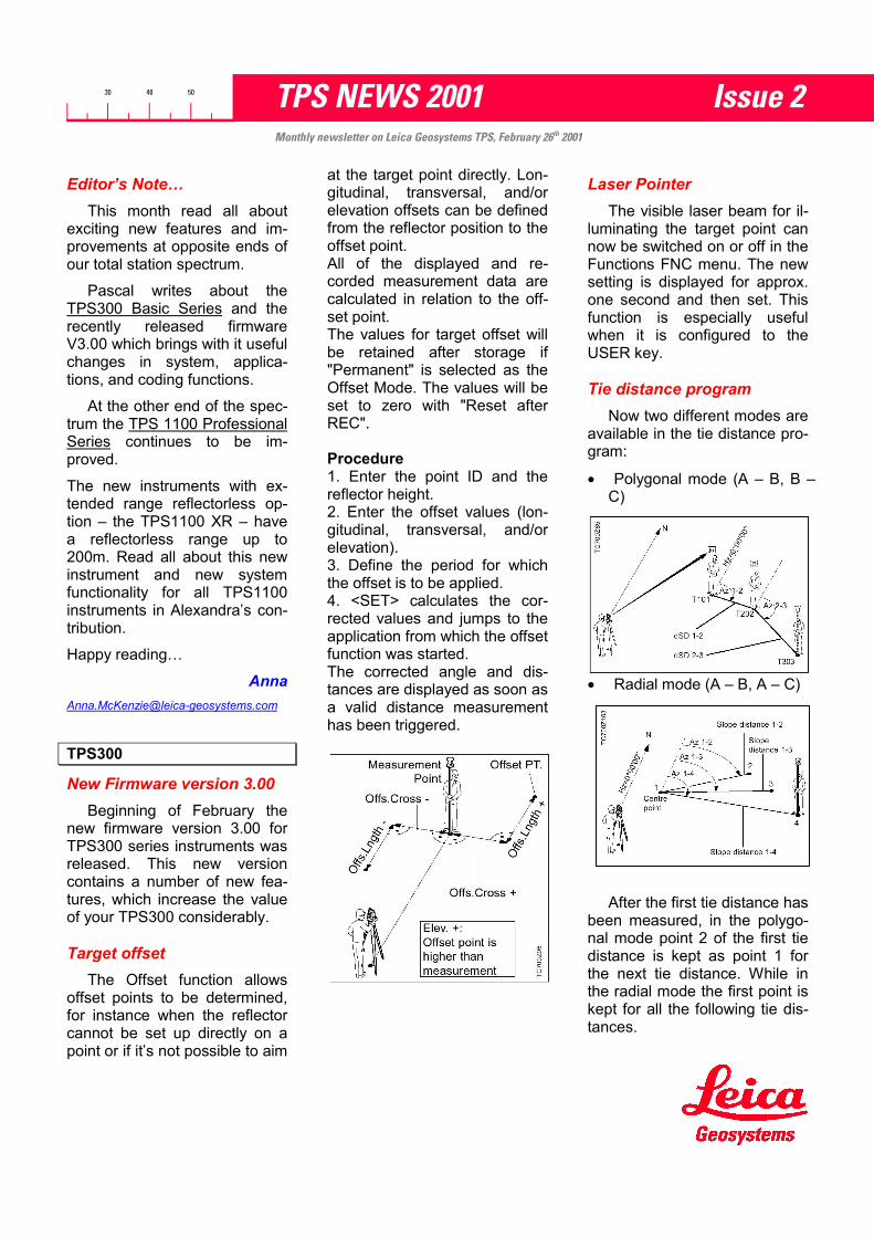
Procedure1. Enter the point ID and thereflector height.2. Enter the offset values (lon-gitudinal, transversal, and/orelevation).3. Define the period for whichthe offset is to be applied.4. <SET> calculates the cor-rected values and jumps to theapplication from which the offsetfunction was started.The corrected angle and dis-tances are displayed as soon asa valid distance measurementhas been triggered.
Laser PointerThe visible laser beam for il-
luminating the target point cannow be switched on or off in theFunctions FNC menu. The newsetting is displayed for approx.one second and then set. Thisfunction is especially usefulwhen it is configured to theUSER key.
Tie distance programNow two different modes are
available in the tie distance pro-gram:
• Polygonal mode (A – B, B –C)
• Radial mode (A – B, A – C)
After the first tie distance hasbeen measured, in the polygo-nal mode point 2 of the first tiedistance is kept as point 1 forthe next tie distance. While inthe radial mode the first point iskept for all the following tie dis-tances.

TPS NEWS 2001 – Issue 2
In both modes the followingvalues are calculated:
• Horizontal distance• Height difference• Bearing• Slope distance
The tie points can either bemeasured online (ALL, DIST –REC, <MEAS>), selected fromthe memory, or input from thekeyboard (<COORD>). Ofcourse, all the results are savedin the memory.
Area programOn the measurement screen
of the area program there is anew button called <COORD>.The surveyor can use it for twodifferent things:
1. First he inputs the pointnumber of the fixpoint hewants to choose from thememory. Then he puts thefocus on the <COORD>-button and presses ENTER.
2. If he wants to input a newfixpoint then he just keys inthe desired point number.After pressing the <CO-ORD>-button the programasks for the co-ordinates, ifthere is no fixpoint storedunder this point number.After he has confirmed hisentries, the program calcu-lates the area using thisnew point.
With this feature a surfacecan now be determined fromtwo different stations. Thismight be necessary if not all ofthe boundary points are visiblefrom the same station.
Number of codes doubledWith the new firmware ver-
sion 3.00 the instrument cancope with codelists which con-tain up to 200 codes. This is the
double amount of codes com-pared to version 2.20.
Code before/after measure-ment
In the menu the user cannow choose between recordingthe code before or after themeasurement. Thus far thissetting was available only in thePC based program “TPSSetup”[email protected]
TPS1100
Reflectorless measurementsup to 200m...
With the newTPS1100 XRangeinstruments youcan measure re-flectorless dis-tances up to 200m(660ft), dependingon the reflectioncapability of thesurface.
Reflectorlessmeasurement isbased on thephase-shift tech-nology. This pat-ented technique emits an ex-tremely narrow visible laserbundle that precisely marks thetarget and guarantees very ac-curate distance measurement.
Spotsize of RL beamAt 20m (66ft) 0.7 x 1.4 cmAt 100m (330ft) 1.5 x 3.0 cmAt 200m (660ft) 3.0 x 6.0 cm
The small laser spotsize at thetarget enables accurate meas-urements also to edges andcorners without the help of spe-
cial corner measurement pro-grams.
This technology enables meas-urements to reflective tapes upto 1000m (3’300ft). You canmeasure up to 7500m (24’600ft)with a single prism and 12’000m(39’500ft) with three prisms.
Beside the new reflectorlesstechnology, the infrared EDMguarantees a precision of2mm+2ppm over the wholemeasurement range from 0 to3000m!
Following table gives an over-view of the technical data fordistance measurement withreflectorless or infrared technol-ogy.
TPS1100 System V2.10 -new functionality
Several wishes have beenrealised in the newest systemsoftware V2.10. A short de-scription of some of the newfunctions follows.

TPS NEWS 2001 – Issue 2
Calibration protocolA protocol of the instrument
calibration results is increas-ingly requested by contractors.V2.10 now allows you to recordthose results to the PC Card ina calibration protocol. The cali-bration parameters before andafter instrument calibration arerecorded to the protocol file withdate and time in the units set onthe instrument.
The registration of the calibra-tion protocol can be activatedfrom the Main Menu under [6],SHIFT [F2]. The information isrecorded in a file named„Calib.log“ in the subdirectory\LOG of the PC Card. The prin-ciple is the same as for the ap-plication logfiles: new informa-tion is added to the logfile ateach instrument calibration.Centre working area
This new function for theRCS mode saves time by thedefinition of working areas. Itallows to centre your currentworking area at any telescopeposition. You define the dimen-sions of the working area onceand then you only need to re-centre it anytime you changestation or survey direction.
Point code andattribute conversion
Point codes and attributescan be now converted fromASCII to GSI and backwardswith the on-board data conver-sion function. Up to three cod-ing information can be con-verted together with the point Idand the coordinates.
Just define a template with thesequence of the coordinatesand coding information (underF2 [CONF], then F3 [ASCII]within the data conversion func-tion) and the conversion runsautomatically from ASCII to GSIor backwards.Reorganise applicationmemory
The possibility to load appli-cation programs directly fromthe PC-Card was the subject oflast year’s newsletter 24/2000.When often loading and delet-ing applications it may happenthat the instrument memorygets too fragmented, whichmakes it impossible to load newapplications. A memory man-agement function is now avail-able on-board the instrument,whereas the option for memoryreorganization is automaticallyan option if [email protected]
News and Events
TPS300 online test reportRecently Al Pepling, a licensedsurveyor and editor for ‘Profes-sional Surveyor’ magazine, hadan in-depth look at a TCR307total station.
Read his glowing report on-lineat: http://www.profsurv.com/psarchiv.htm
� Hands On: Leica TCR307
PublishingIf you have an article you would likepublished in TPS News 2001 whichmay be of interest to other readers,please contact Anna McKenzie [email protected]
The next issue of TPS News will bepublished on 26th March.
Leica Geosystems AGCH-9435 Heerbrugg
(Switzerland)Phone +41 71 727 31 31
Fax +41 71 727 46 73www.leica-geosystems.com

TPS NEWS 2001 Issue 3Monthly newsletter on Leica Geosystems TPS, March 27th 2001
Editor’s Note…In January we released a
new application program forTPS1100 Professional Seriesinstruments. Reference Plane isa useful program with an num-ber of useful applications. Thebasics of this program are de-scribed here. For more informa-tion refer to the TPS1100 Appli-cation Reference Manual whichis included on every TPS SeriesCD.
With TPS1100 firmware V2.10,also released in January, weadded a number of improve-ments, as described in lastmonths newsletter. This monthPhilipp Keller explains the newfunctions of the Data Converterin more detail.
Enjoy!
TPS1100
New Application ReferencePlane
Reference Plane is designedto measure points on or in ref-erence to a plane. As of 2nd
April it will be included in thenew TPS Expert applicationpackage (see below).
Coordinate SystemThe program offers the
choice between a local coordi-nate system (x, y, z), directly onthe plane, and the instrumentcoordinate system (E, N, H).The first step in the program isto decide, which coordinatesystem to use.
With the local coordinate sys-tem the program prompts theuser for the local coordinates ofthe first plane-definition point,thus allowing a coordinate sys-tem independent of the currentsystem values.
Defining the PlaneA plane can be defined by 2-
10 points. Two points define avertical plane, 3-10 points de-fine a tilted plane.
The points used to define theplane can be directly measured,imported from a stored GSI-file,or input manually.
With 4 or more points, a leastsquares adjustment is calcu-lated resulting in a best-fitplane. The program also deter-mines the standard deviation ofthe plane and displays the dif-ference from each definition-point to it.
The defining points can beturned on/off or even deleted.The plane is then recalculatedby pressing F1 [RECALC].
Once the standard deviation isaccepted, the plane can also beshifted by an offset.
Offsets can be input by hand ora point can be measured tooffset the plane through. Theoffset distance is then dis-played.
Measuring Points on thePlane
After the plane definition,points can be measured in ref-erence to the surface.Without a distance measure-mentWith telescope movement thescreen constantly updates thecoordinates of the point on theplane the instrument is pointingto (- - - - , see picture).
With a distance measurementIf a distance is measured to apoint ( ), coordinates of themeasured point are determinedin the selected system. Thedistance from the point to theplane is also calculated anddisplayed.
ConfigurationLike every Leica Application
program Reference Plane has aConfiguration Menu. This islocated under Shift F2 in thefirst Application menu.

TPS NEWS 2001 – Issue 3
The settings include Max∆∆∆∆dwhere the user can set themaximum allowed distance of aplane definition point from thedefined plane. This helps elimi-nate gross errors in the planedefinition.
Another setting is Logfileon/off. If on, all relevant planeinformation is recorded in a textfile (see example, right).
With its many settings and op-tions Reference Plane can beused for a number of applica-tions ranging from parking lotsto roofs and everything in [email protected]
TPS1100
Data converterWith the new TPS1100 firm-
ware V2.10 it is possible to con-vert point code and one or twoattributes from ASCII to GSI orTDS and back with the on-board data converter.Defining a templateUnder F2 [CONF] (within thedata conversion function) thenF3 [ASCII] you can define atemplate with the sequence ofthe coordinates and codinginformation in your ASCII file.This template is used for ASCIIsource and output files.ExampleYou have an ASCII coordinatelist with no heights but pointcode and one attribute whichyou want to convert to GSI. Thesequence of your ASCII file isthe following:
PtId,N,E,PC,Attr1.So you have to define yourtemplate as following:
Delimiter : Comma▼Id Pos : 1▼East Pos : 3▼North Pos : 2▼Height Pos : None▼Pt. Code Pos: 4▼Attrib 1 Pos: 5▼Attrib 2 Pos: None▼Skip a columnIf you have an ASCII File with acolumn that you don’t want toconvert you can skip it.
ASCII File example:
PtId,E,N,H,XY,PC1,-3.653,1.289,0.994,XY,TR2,-2.364,5.643,1.563,XY,TR3,-2.645,6.543,2.540,XY,ST4,-2.857,1.723,1.034,XY,WL
If you don’t want to convert the5th column (XY) just skip theposition 5 in your template:Delimiter : Comma▼Id Pos : 1▼East Pos : 2▼North Pos : 3▼Height Pos : 4▼Pt. Code Pos: 6▼Attrib 1 Pos: None▼Attrib 2 Pos: None▼
⇒ GSI:
Is this template used for theASCII output File, the 5th col-umn will be filled with the value“zero”.
TPS NEWS 2001 – Issue 3
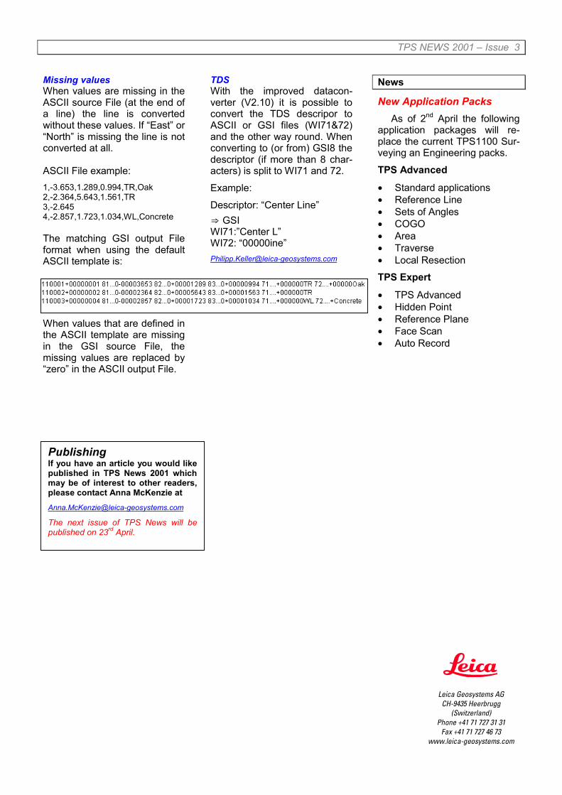
Missing valuesWhen values are missing in theASCII source File (at the end ofa line) the line is convertedwithout these values. If “East” or“North” is missing the line is notconverted at all.
ASCII File example:1,-3.653,1.289,0.994,TR,Oak2,-2.364,5.643,1.561,TR3,-2.6454,-2.857,1.723,1.034,WL,Concrete
The matching GSI output Fileformat when using the defaultASCII template is:
When values that are defined inthe ASCII template are missingin the GSI source File, themissing values are replaced by“zero” in the ASCII output File.
TDSWith the improved datacon-verter (V2.10) it is possible toconvert the TDS descripor toASCII or GSI files (WI71&72)and the other way round. Whenconverting to (or from) GSI8 thedescriptor (if more than 8 char-acters) is split to WI71 and 72.
Example:
Descriptor: “Center Line”⇒ GSIWI71:”Center L”WI72: “00000ine”[email protected]
News
New Application PacksAs of 2nd April the following
application packages will re-place the current TPS1100 Sur-veying an Engineering packs.
TPS Advanced
• Standard applications• Reference Line• Sets of Angles• COGO• Area• Traverse• Local Resection
TPS Expert
• TPS Advanced• Hidden Point• Reference Plane• Face Scan• Auto Record
PublishingIf you have an article you would likepublished in TPS News 2001 whichmay be of interest to other readers,please contact Anna McKenzie [email protected]
The next issue of TPS News will bepublished on 23rd April.
Leica Geosystems AGCH-9435 Heerbrugg
(Switzerland)Phone +41 71 727 31 31
Fax +41 71 727 46 73www.leica-geosystems.com

TPS NEWS 2001 Issue 4Monthly newsletter on Leica TPS, April 30th 2001
Editor’s Note…In the last few years distance
measurement to reflector tapeshas become a common sur-veying practice. All Leica TPSinstruments support measure-ment to tapes and there are anumber of tape sizes and colorsavailable in the market today.Leica alone sells three differentsizes of self-adhesive “RetroTargets”, ranging in size from20x20mm for measurementsfrom 2-40m to 60x60mm for the60-180m range.
Alexandra has written an in-teresting article on reflector tapemeasurement with the TPS1100series instruments. These func-tions are very similar on theTPS700 and TPS300 families ofinstruments, just the location ofthe mentioned dialogs is differ-ent.
As always we hope this in-formation will help you to betterunderstand and use our instru-ments.
TPS1100
Distance measurements toreflector tapes
TPS1100 instruments canmeasure to reflector tapes withthe integrated standard infraredEDM or with the “long range”distance measurement optionavailable on TCR, TCRM, andTCRA instruments. The meas-urement settings and some tipsand hints for distance meas-urements to reflector tapes arethe subject of this column.
Measurement with infraredEDM
The infrared EDM is the bestoption for accurate distancemeasurements to reflectortapes. Thus, it is essential toselect the appropriate target inorder to meet the specified ac-curacy of 3mm+2ppm.
Check your target set-tings under [FNC] and
[2], “Reflector selection” or [3],“EDM program selection”:
The target must be set to “LeicaRefl. tape” whereas the additionconstant is automatically up-dated to 34.4mm.
With these settings typicalranges from 1.5m up to 250m(800ft) can be measured to a60x60cm reflector tape undernormal atmospherical condi-tions.Measurement with reflectorlessEDM
The reflectorless EDM of theTPS1100 instruments allowslong range measurement toreflector tapes. Therefore, theappropriate EDM measurementprogram and target should beselected.
Check your settingsunder [FNC] and [3],
EDM program selection:
The EDM program must be setto “Standard Long” and the tar-get to “Leica Refl. Tape”.
Typical ranges up to 1000m(3300ft) can be measured withTPS1100 instruments withXRange option to a 60x60cmreflector tape under normal at-mospherical conditions.
The accuracy depends on theorientation of the reflector tapein relation to the telescope lineof sight:
• 5mm+2ppm for tapes per-pendicular to the line ofsight.
• up to 10mm+2ppm for in-clined tapes.
In order to guarantee the speci-fied accuracy, the red laserbeam must be well aligned withthe telescope line of sight. Theadjustment of the red laser canbe easily checked in the officeor in the field with the targetplate and the appropriatescrewdriver available in theinstrument case. Adjustmentcan be done with the screwslocated on the bottom side ofthe telescope.
If the red laser beam is notperfectly aligned, you can getthe best possible results fordistance measurement bysearching for the maximumEDM signal. Do this by usingthe “EDM test signal function”under [FNC], [8].

TPS NEWS 2001 – Issue 4
After distance measurement,don’t forget to precisely aim atthe target for correct Hz anglemeasurement. The instrumentmust configured in “VFree”mode for correct V angle re-aiming.
Note that distance measure-ments to target plates may alsobe run by using the reflectorlessEDM program:
However, this EDM pro-gram is not recom-
mended for measurements toreflector tapes as the “StandardLong” program guaranteesmore reliable results. Further-more the reflectorless programshould not be used for dis-tances over 768m (2480ft),which corresponds to the ambi-guity of this [email protected]
News and Events
Leica Geosystems in theBalkans
Leica Geosystems AG wasrecently awarded a contract bythe SDC (Swiss Agency forCooperation and Development)to supply 25 TPS300 instru-ments, 7 GPS500 Systems, and21 Liscad software packages tobe delivered to the Kosovo.
These units will be used inthe Kosovo Cadastre SupportProgram for the reconstructionand development of the cadas-tral register which was for themost part destroyed during thewar. The objective of this pro-gram is a well functioning realproperty and land market sup-porting democratic and sustain-able development and eco-nomic growth in the Kosovo.
Product specialists fromHeerbrugg had the opportunityto train the local surveyors onthe Leica equipment. The con-tract and the introductorycourse were a major successfor Leica Geosystems AG andwill help to intensify our pres-ence in the Balkan region.
PC-cardsTPS1100 instruments sup-
port PCMCIA SRAM cards andPCMCIA ATA flash cards. Flashcards with a capacity of 4 to32MB are supported.
When using flash cards, it isvery important to insert the cardcorrectly into the housing. ThePC-Card is inserted correctly ifthe red TPS arrow symbol isvisible and if the PC-card con-nector faces upwards whenclosing the PC-card housing.
A helpful sticker (see above)showing the way to insert thePC-card will be available soonin the PC-card housing of theTPS1100 instruments. A cor-rection of the housing designhas also been made in order toprevent inserting the PC-cardon the wrong side.
PublishingIf you have an article you would likepublished in TPS News 2001 whichmay be of interest to other readers,please contact Anna McKenzie [email protected]
The next issue of TPS News will bepublished on 28th May.
Leica Geosystems AGCH-9435 Heerbrugg
(Switzerland)Phone +41 71 727 31 31
Fax +41 71 727 46 73www.leica-geosystems.com

TPS NEWS 2001 Issue 5Monthly newsletter on Leica Geosystems TPS, May 28th 2001
Editor’s Note…Have you ever wondered
who the people are that designthe functions of the instrumentsand determine the content ofthe software? We call themApplication Engineers and atLeica they all have a back-ground in surveying. To putfaces to names you’ve probablyrun across before (like Alexan-dra Zdravkovic or WolfgangHardegen) we decided to intro-duce the TPS-Team to you.Read about this internationalgroup and the work they do onpage 2.
On a more technical sideAlmut has written her first con-tribution to TPS NEWS thisyear. Read her article to find outabout an accessory we some-times take for granted.
Also in this edition of TPSNEWS you will find a brief re-fresher on loading and deletingApplications on your TPS1100instrument. A very useful func-tion – try it sometime!
TPS Accessories
BATTERIESand how to treat them….
A reliable power supply isone of the most important con-ditions for all surveying tasks inthe field. But how should wetreat our batteries in order toretain their performance andguarantee a long life?
The lifetime of a battery is pri-marily defined by the cell qual-
ity, the charging method, andthe charging, discharging andstorage temperature.
This article provides a quickoverview on how to maximizethe battery performance andservice life by maintaining,storing, charging, and dis-charging correctly.Cell types
Leica Geosystems usesnickel-cadmium (NiCd) andnickel-metal hydride cells(NiMH). The cell type is indi-cated on the battery.Charging…
The charging temperature(ambient temperature) has asignificant effect on the life ofthe batteries. Charging at hightemperatures can cause loss ofcapacity. These losses in ca-pacity are irreversible. Evenwith several charging and dis-charging cycles the originalcapacity can no longer beachieved.
For optimal charging the ambi-ent temperature should be aslow as possible, i.e. between+10°C and +20°C. The permit-ted temperature range is be-tween 0°C and +35°C.
NiCd batteries have up to 1000charge cycles (charging anddischarging), NiMH have up to800 charge cycles.
Whenever possible, chargebatteries between +10°C and+20°C.Operating…
The operating temperaturehas a significant effect on theuseful battery capacity. Gener-ally, Leica Geosystems batter-ies can be operated from –20°Cto +55°C.
But when operating at low tem-peratures the useful capacitydrops rapidly. For example, at-20°C the useful capacity is onlyabout 70% when compared to+20°C.
On the other hand, continuoususe in the upper temperaturerange (> 45°C) shortens the lifeof the battery.
Low operating temperaturessignificantly reduce the usefulcapacity. Very high tempera-tures can shorten the batterylife.Storing…
Batteries can be stored from-40°C to +50°C.
NiMH batteries must always bestored charged, and must berecharged after 180 days at thelatest. When stored in the dis-charged state for an extendedperiod irreversible damage canbe caused, i.e. the original ca-pacity can no longer bereached.
NiCd batteries can be stored inany charge state for an unlim-ited period.
The self-discharge of the bat-tery is dependent on the tem-perature and the atmospherichumidity. High temperaturesand high atmospheric humidityaccelerate self-discharging.
Self-discharging per month:Temp. NiMH NiCd0°C 10% 7%+20°C 30% 15%+40°C 90% 30% Whenever possible, store
batteries between 0°C and+20°C in a dry environment.NiMH batteries must be storedcharged.

TPS NEWS 2001 – Issue 5
“Memory Effect”The “memory effect” occurs
if the same charging and dis-charging conditions are con-tinuously applied to a battery.Then, the battery no longer pro-vides the full capacity and theoperating time per batterycharge reduces.
Whenever the “memory effect”occurs, the battery should berefreshed (i.e. fully charged anddischarged 1 to 3 times). Dis-charging can be either donewith the charger GKL122 or inthe instrument by operating untilthe instrument switches offautomatically.
The “memory effect” particularlyoccurs on NiCd batteries.
If the capacity of your batterydrops noticeably it should befully discharged and recharged1 to 3 times.
TPS Team
The TPS Application groupcurrently consists of 12 people,all with surveying backgrounds.It is their job to define the totalstation and digital level featuresand functions according to mar-ket demand and state-of-the-arttechnology. In addition theyhelp design the accompanyingsoftware, offer support andtraining to sales and supportgroups in the selling units world-wide, and write articles for TPSNEWS.
Back row, left to right:Wolfgang has been involved inthe development of instrumentsfor Leica customers for morethan 10 years. He’s also theonly one of us originally fromthe Rhine valley. He is product
manager for the TPS700 Per-formance Series.
Jimmy started work for thesoftware group 3½ years agoand recently joined TPS. AnAustrian, he works on innova-tion projects and the usualtesting and project work familiarto us all.
Olaf has many years with Leicaunder his belt. Originally fromBerlin, Germany he has madehis home in the Rhine-valley forthe past 30 years. He has helda number of positions within thefirm and is now our TPS Pro-gram leader.
Susanne also hails from Ger-many. She spent last summerhere testing TPS1100 and ATRas a student. Lucky for us shedecided to come back and workfor us full time. She has beenhere for 9 months now andworks with TPS700.
Almut migrated to TPS from theSoftware group recently. Aftergraduating in Germany shemoved to Switzerland 3 years
ago and now works on TPSsoftware.
Of the Application EngineersFelix is the most senior. For thepast 15 years he has workedprimarily on the development ofdigital levels. Felix is from Swit-zerland.
An experienced surveyor,Marco came to us this April andhas since been working ondigital levels. He is also Swiss.
Front row, left to right:Anna Corinne (Cori), an Ameri-can schooled in Germany cameto Leica 2 years ago and is re-sponsible for TPS1100 on-board Application programs.
Philipp, born and educated inSwitzerland, started working forLeica 2 years ago. Mostly heworks on TPS1100 andRCS1100 but fills in whereverhe is needed.
Alexandra has been in Heer-brugg for 5 years. She is fromwestern (French-speaking)Switzerland and is productmanager for the TPS1100 Pro-fessional Series.

TPS NEWS 2001 – Issue 5
Leica Geosystems AGCH-9435 Heerbrugg
(Switzerland)Phone +41 71 727 31 31
Fax +41 71 727 46 73www.leica-geosystems.com
Juergen first came to Leica as auniversity student and returnedafter getting his degree in Vi-enna. He has been here for 2years now. His responsibilitieslie with the TPS1100 family.
A number of product familieshave been developed with Pas-cal’s input (left). Working forLeica for 3 years he is currentlyproduct manager for theTPS100 and TPS300 families.
Bayren (right) joined us fromHamburg, Germany this spring.He has a background in hydro-graphic applications and is nowinvolved in our TPS100/TPS300product development.
TPS1100
Loading Applications fromyour PC-card
With firmware V2.03 weadded a feature that has hadresounding success. Being ableto load Application programs inthe field from a PC-card is apractical and often used func-tion.
In June 2000 we wrote a TPSNewsletter (24/2000) about thisfunction. Some questions havesince come up that need clarifi-cation.
To load an application from aPC-card the files must be in thefollowing directory:
GSI
TPSAPPL
PC-Card directory
LANG*.prg*.lxx
You need at least two files toload a TPS1100 application.These are the *.prg and the*.lxx files. The *.prg file is theprogram file and the *.lxx filecontains the language. In addi-tion to these two files you canalso load an *.app file contain-ing special configuration set-tings. All files must have thesame version number or theycannot be loaded.
You can get the files off yourcurrent TPS Series CD in thelanguage folder of the TPS1100Software directory. You maynotice that there are two lan-guage folders titled English.One is the standard, Leica de-fault English and the other isUS-English containing special*.app files with the North Ameri-can default settings.Why use an *.app file?
Use the *.app files in thelanguage folders to get the de-fault configuration for your lan-guage/country. These are thesettings that you are familiarwith.
For example, to load “Stakeout”in Italian you should select thefollowing files from the Italianfolder:
• Stake203.prg
• Stake203.lit
• Stake203.app
Loading the *.app file meansgetting the Italian default set-tings which include Graphicsmode set to “From Station” in-stead of “No Graphics” as in theLeica default.Tip:
To ensure proper loading ofthe software, delete the old ap-plication on the instrument be-fore loading the new one. Thiscan also be done on-board.
To get to the Loading dialogfrom the Main Menu press 5)Configuration; 4) Load…; 3)Load Application. Delete anapplication by pressing F5“DEL-A” in this dialog.Watch out!
If you have two versions ofan application on your PC-cardthe instrument will only recog-nise the lower version numberand will load these files, not thenewer version.Reorganising memory
With all the loading and de-leting possibilities the memoryoccasionally gets fragmented,making it impossible to fullyload an application. If this hap-pens with firmware versionsV2.10 and higher, the instru-ment will offer to reorganise thememory for you (TPS NEWS02/2001). This takes a few min-utes but is well worth the wait.You can then resume loadingapplications.
PublishingIf you have an article you would likepublished in TPS News 2001 whichmay be of interest to other readers,please contact Anna McKenzie [email protected]
The next issue of TPS News will bepublished on 25th June.

TPS NEWS 2001 Issue 6Monthly newsletter on Leica Geosystems TPS, June 25th 2001
Editor’s Note…We are now finally heading
into summer in Switzerland.This is a great season to be asurveyor, outside in beautifulweather all day - the envy of alloffice workers!
This month’s article featuresan application program that canreally make your life easier.COGO for TPS1100 series in-struments is a very useful toolby anyone’s standards and Iurge you to try it out and dis-cover for yourself the manypossibilities it offers. Remem-ber, every TPS1100 applicationprogram has a DEMO-modethat offers the full programfunctionality. It just won’t let youstore any data.
Also this month, Bayren vis-ited the annual German Hydro-graphic conference and hasincluded a brief summary of thisevent.
May the sun shine…
TPS1100
COGO Application ProgramCOordinate GeOmetry is a
versatile mathematical tool thatenables you to do a number ofcalculations in the field withouthaving to dig out your calculatoror remember the formulas.
The program is divided into 5groups, each of which containsa variety of functions.
Inverse & TraverseUse the Inverse module to
calculate azimuth and horizontaldistance between two knownpoints.
Traversedoes theopposite bydeterminingcoordinatesof a pointgiven theazimuth anddistancefrom a known point. You canalso use additional offsets todefine the new point (see pic).
Once calculated, the point canbe set out by pressing F5 –STAKE. This starts the regularStakeout application programand allows you to directlystakeout the point.
On the 2nd level of the Traversemodule (SHIFT-F5: MODIF)there are additional dialogs tomodify/recalculate the enteredvalues. Both the azimuth (orbearing) and distance can bemultiplied and/or divided. Addi-tional values can then be addedand subtracted.
E.g. 40.000 x 3 = 120.000 / 2 =60.000 + 10.000 = 70.000.Confirm your final result with F1– CONT to use it in the Trav-erse calculation.
Intersections…There are four intersection
methods to choose from. Thecoordinates of the first and sec-ond points are always required.The other necessary informa-tion varies according to yourselection. In most methods youcan enter offsets in addition tothe required values. The resultsare always coordinates of a newpoint.
Bearing-Bearing: add theazimuths from pts. #1 and
#2.
Bearing-Distance: alsoinput azimuth from pt. #1
and horizontal distance from pt.#2.
Distance-Distance: hori-zontal distances from pts.
#1 and #2 are known.
Intersection by Points:additional points #3 and
#4 are used.
Some of the methods have twocorrect solutions. Toggle be-tween them by pressing F2 –OTHER.
The results can always bestaked out directly by pressingF5 – STAKE.
Offsets…The Offsets options are a
subset of the possibilities of-fered by the Reference Lineprogram.

TPS NEWS 2001 – Issue 6
Distance-Offset returns the∆Offset and ∆Line values of apoint in relation to a definedbaseline.
Set point by Dist-Offset calcu-lates the coordinates of a pointfrom the entered ∆Offset and∆Line values.
3 Point ArcThis program calculates the
coordinates of the center of anarc as well its radius using threepoints. The center point can bestaked out by pressing F5 –STAKE after calculation.
Good to knowEvery time a point (i.e. coor-
dinates) is required in COGOyou have three options. Youcan import it from any GSI-fileon your PC-card, measure thepoint with your instrument, ormanually input the coordinatesusing the keypad. You alwayshave a choice!
It is also important to knowthat only two applications canbe run at any one time on yourTPS1100. For example if youare already running Stakeoutand open COGO to make acalculation, the STAKE key togo stakeout the point will notwork since this key starts theprogram. You must either storethe point and then return to theopen Stakeout program or closeStakeout before starting COGO.
COGO is included in theTPS Advanced and TPS Expertapplication packages.
News and Events
Hydrographic ConferenceThe author had the chance
to visit this years‘ conference ofthe German Hydrographic Soci-ety which took place from 18th
to 20th June 2001 in the lovelycity of Potsdam. Well known forits history and worldwide aca-demic reputation as a center forgeodesy and gravity research itwas the perfect surrounding forthe 16th Hydrographic Confer-ence. Nearly twenty lecturescovered the different aspects ofhydrography during the 3 daymeeting:
• Multibeam echosounders,
• Current measurement andbathymetric data analysis,
• Telemetry and RTK datalinks,
• Control and maintenance ofon/offshore construction,
• Environmental monitoring,Coastal Zone Managementand shipping safety.
In addition several firms pre-sented their up-to-date hydro-graphic instruments and appli-cations varying from echo-sounders (e.g. STN Atlas Ma-rine Electronics, Simrad, ELACNautik, Innomar), gyrocom-passes and inertial navigationsystems (e.g. iXSEA) to GPSsensors. Leica Geosystemswas present as well with ourcurrent GPS technology and theTPS1100 Professional seriestotal stations. These exhibitsattracted many attendees,mainly from German FederalAgencies.
New Driver for OmniDriveA new driver for the Omni-
Drive PC-card reader will beavailable as of July 2001. DriverV1.18 will continue to work withall standard PC operating sys-tems (DOS, WIN 3.X, WIN95/98, Win NT4.0, WIN ME,WIN2000).
In the future OmniDrives will nolonger be delivered with 3.5”diskettes. These will be re-placed with CD’s which will nowalso include the “PC-Card Man-ager” program. This includesmany useful tools to help youformat, repair, and work with PCcards.
Instead of the old keyboradpower adapter DIN2, the Omni-Drive will now be delivered witha power adapter for a USB port.The small PS2 power adapterwill remain in the box.
PublishingIf you have an article you would likepublished in TPS News 2001 whichmay be of interest to other readers,please contact Anna McKenzie [email protected]
The next issue of TPS News will bepublished on 30th July.
Leica Geosystems AGCH-9435 Heerbrugg
(Switzerland)Phone +41 71 727 31 31
Fax +41 71 727 46 73www.leica-geosystems.com

TPS NEWS 2001 Issue 7Monthly newsletter on Leica Geosystems TPS, July 27th 2001
Editor’s Note…WHEN DID YOU LAST CALIBRATEYOUR INSTRUMENT??
Modern surveying equipmentachieves high levels of accu-racy without you having to jumpthrough any hoops but tomaintain these levels they mustbe calibrated regularly.
Follow Juergens advice to avoidproblems stemming from cali-bration, collimation, and correc-tions.
Our article on Calibration pro-cedures is based on TPS1100Professional Series instrumentsbut the content is valid for anytotal station.
TPS General
Calibration - The practicalpart
Very often users expectmodern electronic surveyinginstruments to correct and com-pensate instrument errorsautomatically – just go andmeasure. Well, this is true, aslong as some basic rules arefollowed.Single face measurements
With two face measurementsmost of the instrument errorsare eliminated when averagingthe measured angles. But asone face measurements areusually the standard method itis most important to determinethe following instrument errors:
• Line-of-sight error
• Vertical index error
• Compensator index
• ATR collimation
Great care must be taken dur-ing the calibration process, be-cause with one face measure-ments you will be affected bythe accuracy of the errors de-termined – wrong correctionscause inaccurate measurementresults.When to calibrate your instru-ment
Instrument errors are deter-mined and set to zero duringthe production process. Never-theless the values can changedue to mechanical shock, tem-perature changes, rough han-dling, etc. Always keep in mindthat a total station is a very se-sitive high precision instrumentthat should be handled withcare. Therefore the instrumentshould be calibrated regularly.Additionally calibration shouldbe done in the following cases:
• before first use
• after long storage periods
• after big temperaturechanges
• after rough or long trans-portation
• periodically for high accu-racy jobs
What to look out forGood atmosphericconditions, i.e. nostrong heat shimmer,are essential. Beforeyou start calibration
make sure that the instrumenthad enough time to adapt to theambient temperature. The ruleof thumb is that the time for
acclimatization should be atleast 20 minutes or 2 minutesper 1°C of temperature differ-ence. Make sure that the in-strument is not exposed to di-rect sunshine, because this maycause heating of the instrumentfrom one side and thereforeinfluence the accuracy of yourmeasurements. Use an um-brella if necessary.Automatic correction
After calibrating your instru-ment the instrument errors aredetermined and the softwarecontinuously applies the correc-tions to your measurements.Remember that this is differentfrom the mechanical adjustmentof instrument errors as it wasdone with mechanical theodo-lites. If you tilt the telescope upand down you will notice thatalthough the horizontal positionis fixed the horizontal anglereading changes by smallamounts as well. What you seeis not a wrong behavior of yourinstrument but the automaticerror compensation working.
The Theory - Instrument er-rors
Before we can discuss theinstrument errors we have tofamiliarize ourselves with thevarious instrument axes.Instrument axes
The three axes of a totalstation are the Vertical axis V,the Tilting axis T and the Line ofsight L.

TPS NEWS 2001 – Issue 7
Assuming we lived in a perfectworld we could consider thefollowing conditions to be al-ways true:
• L is perpendicular to T
• T is perpendicular to SAs we live in the real world un-fortunately none of these condi-tions can be fulfilled. Unavoid-able errors in the productionprocess, mechanical stresses,temperature changes, etc. leadto small deviations that cause aline of sight error and a tiltingaxis error.Line of sight error (Hz-collimation error)
The line of sight error iscaused by the deviation c be-tween the optical line of sightand the line perpendicular to thetilting axis.
This error affects all horizontalcircle readings and increaseswith steep sightings.
The following table shows theinfluence of a line of sight errorof c=10” for different vertical-angles:
V angle error in Hz90° 10”60° 12”30° 20”
This effect can be eliminated byprecisely defining the line ofsight error with the instrument’sonboard calibration function orwith two-face measurements.Tilting axis error
The tilting axis error iscaused by the deviation a of themechanical tilting axis from theline perpendicular to the verticalaxis
This error has no effect on ex-actly horizontal sightings butincreases with steep sightings.
The following table shows theinfluence of a tilting axis error ofa=10” for different vertical an-gles:
V angle Error in Hz90° 0”60° 6”30° 17”
This effect can be eliminated aswell by precisely defining thetilting axis error with the instru-ment’s onboard calibration
function or with two-face meas-urements.Standing axis error
This error differs from theprevious one because it is notan instrument error but a setuperror. Nevertheless it is veryimportant and shall be men-tioned here. If the instrument isnot leveled properly the verticalaxis of the instrument does notcoincide with the plumb line.This affects both the horizontaland the vertical angle readings.A standing axis error can notbe eliminated by two facemeasurements. Thereforespecial care should be takenwhen leveling the instrument.However, if switched on, theelectronic compensator willmeasure small tilts of the in-strument and apply the accord-ing corrections for horizontaland vertical angles.Compensator index error
The principle of the elec-tronic compensator is quitesimilar to that of a bulls eyebubble. It mainly consists of asmall container filled with aspecial fluid. Due to gravity thesurface of this fluid is alwayshorizontal. Sensors are used todetermine the longitudinal andlateral tilt of the instrument.
In order to determine correcttilt values these sensors need tobe adjusted from time to timewith the onboard calibrationfunction.

TPS NEWS 2001 – Issue 7
If the compensator index valuesare wrongly determined tiltreadings are wrong. This affectsthe measurements in a similarway as a standing axis error.Vertical index error
A vertical index error i existsif the 0°-180° line of the verticalcircle does not coincide with theinstrument’s mechanical verticalaxis.
The V-index error is a constanterror that affects all vertical an-gle readings. Same as the lineof sight error and the titling axiserror this effect can easily beeliminated by precisely deter-mining the vertical index errorwith the instrument’s onboardcalibration function or with two-face measurements.ATR Calibration
The ATR collimation error isthe angular divergence betweenthe line of sight and the cameraaxis. The ATR calibration rou-tine allows to determine thealignment of the center of theATR camera with the opticalline of sight. This is especiallyimportant in order to receivesimilar results when mixing ATRmeasurements with manualmeasurements to prisms.
The calibration of the ATRneeds some extra care. Evenunder good atmospheric condi-tions there will be a little air
shimmer that makes the pictureof the prism wander around thetelescope’s field of view andconsequently also on the ATRcamera. To filter out these at-mospheric effects follow theprocedure below:
Start the onboard ATR cali-bration and follow the instruc-tions on the display. After youhave aimed to the prism in bothfaces the first time the followingdialog shows up on TPS1100instruments:
Choose “MORE” [F4] to takemore measurements. Repeatthe procedure two to threetimes. The values for σATR Hzand σATR V should decreaseas you repeat the process. Afterthe last run they should beclose to zero.
News and Events
New firmware version 3.50As of July the new firmware
version 3.50 for TPS300 seriesinstruments was released. Thisnew version contains the on-board application ‘Referenceline’ which increases the valueof your TPS300 considerably.Reference Line program
This program can be used toset-out or inspect building lines,straight sections of roads, sim-ple groundwork etc. A reference
line can be defined in relation toa known base line (e.g. an ex-isting boundary line of a buildingsite). It can then be shifted androtated to define the requiredreference. All measured pointsrefer to the reference line.
The reference line programhas been explained in moredetail in two previous issues ofTPS Newsletters (22/2000 and28/2000). Refer to these fromore information on this pro-gram.
New Team MembersWe are very pleased to wel-
come two new team membersto the TPS Application group.Marco Mueller is our newTPS100 and TPS300 ProductManager and Alex Lototzky hasjoined the TPS1100 group fromAustralia.
PublishingIf you have an article you would likepublished in TPS News 2001 whichmay be of interest to other readers,please contact Anna McKenzie [email protected]
The next issue of TPS News will bepublished on 27th August.
Leica Geosystems AGCH-9435 Heerbrugg
(Switzerland)Phone +41 71 727 31 31
Fax +41 71 727 46 73www.leica-geosystems.com
TPS NEWS 2001 Issue 8Monthly newsletter on Leica TPS, August 27th 2001
Editor’s Note…Last month Jürgen gave us witha detailed description of possi-ble instrument errors and howto avoid them.
This month Philipp was luckyenough to accompany a sur-veying team for a day and seethe theory put into practice.
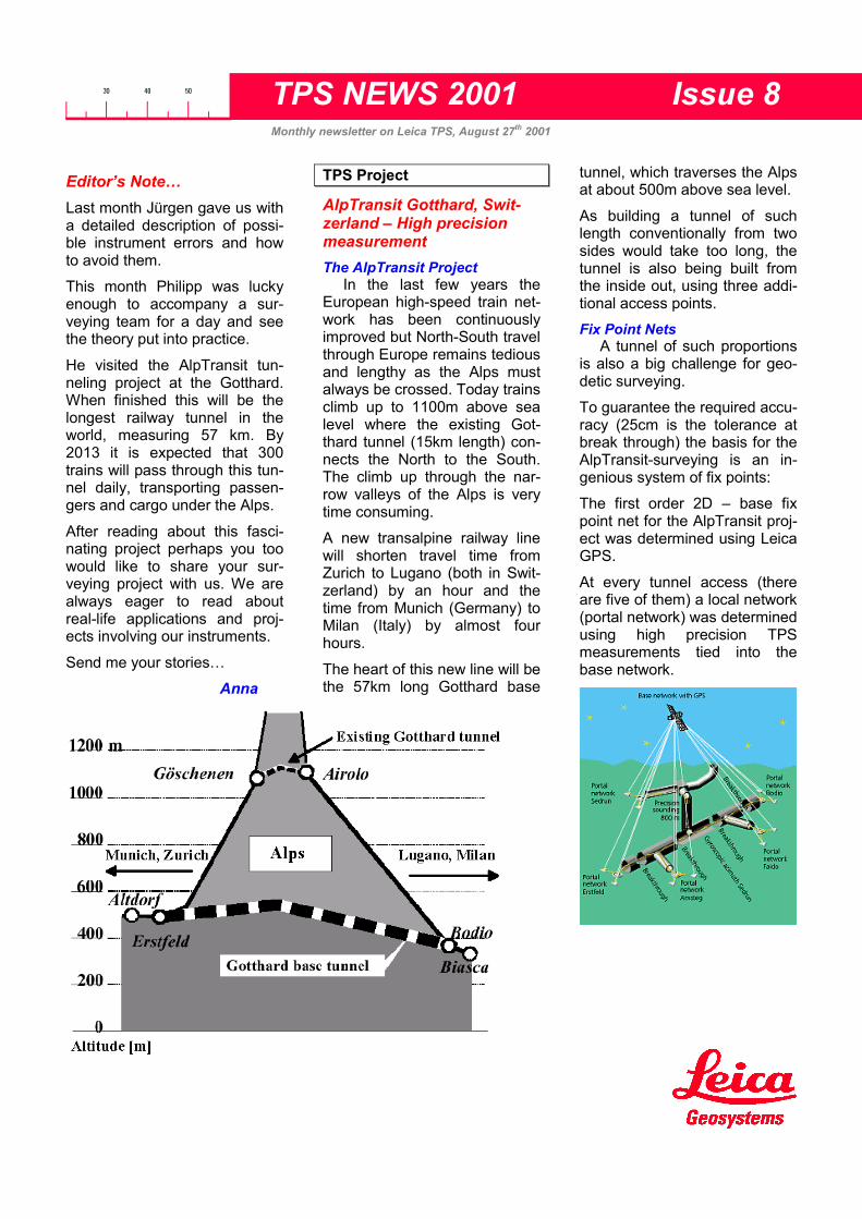
He visited the AlpTransit tun-neling project at the Gotthard.When finished this will be thelongest railway tunnel in theworld, measuring 57 km. By2013 it is expected that 300trains will pass through this tun-nel daily, transporting passen-gers and cargo under the Alps.
After reading about this fasci-nating project perhaps you toowould like to share your sur-veying project with us. We arealways eager to read aboutreal-life applications and proj-ects involving our instruments.
Send me your stories…
Anna
TPS Project
AlpTransit Gotthard, Swit-zerland – High precisionmeasurementThe AlpTransit Project
In the last few years theEuropean high-speed train net-work has been continuouslyimproved but North-South travelthrough Europe remains tediousand lengthy as the Alps mustalways be crossed. Today trainsclimb up to 1100m above sealevel where the existing Got-thard tunnel (15km length) con-nects the North to the South.The climb up through the nar-row valleys of the Alps is verytime consuming.
A new transalpine railway linewill shorten travel time fromZurich to Lugano (both in Swit-zerland) by an hour and thetime from Munich (Germany) toMilan (Italy) by almost fourhours.
The heart of this new line will bethe 57km long Gotthard base
tunnel, which traverses the Alpsat about 500m above sea level.
As building a tunnel of suchlength conventionally from twosides would take too long, thetunnel is also being built fromthe inside out, using three addi-tional access points.Fix Point Nets
A tunnel of such proportionsis also a big challenge for geo-detic surveying.
To guarantee the required accu-racy (25cm is the tolerance atbreak through) the basis for theAlpTransit-surveying is an in-genious system of fix points:
The first order 2D – base fixpoint net for the AlpTransit proj-ect was determined using LeicaGPS.
At every tunnel access (thereare five of them) a local network(portal network) was determinedusing high precision TPSmeasurements tied into thebase network.

TPS NEWS 2001 – Issue 8
The tunnel networks will bemeasured from these portalnetworks by high precision trav-ersing.
An independent network wasestablished for the elevationsusing Leica NA3003 and preci-sion leveling methods.High precision traverse
Gruenenfelder AG is a Swisssurveying company equippedwith Leica instruments. Theyare part of the consortium thatis responsible for the surveyingtasks at the Gotthard base tun-nel.
For one day a team of their sur-veyors was accompanied by aLeica Application Engineer whoassisted them in doing a highprecision traverse at the southend of the tunnel in Bodio. Thegoal was to get highly accurate2D - coordinates of the fixpoints in the tunnel.
Following is a step-by-step re-port of the procedures used thatday to achieve the requiredaccuracy.Measurement Procedures
The start of the traverse isright at the tunnel portal.
The instrument (a TCA2003) issetup over a fix point of theportal network with visibility intothe tunnel.
This is done right at the arrivalso the instrument has time toacclimatize to the ambienttemperature during the meas-urement preparations. Thegreater the temperature differ-ences are the longer an instru-ment has to be acclimatizedbefore starting measurements.
A rule of thumb says to wait twominutes per degree tempera-ture change. This is due to thefact that heating up or coolingdown of the instrument can leadto internal physical tension,which can affect instrumentaccuracy.
To protect the instrument andthe tripod from the sun a sun-shade is mounted. The intenselight of the sun heats up instru-ment and tripod and leads tosmall asymmetrical expansions.
The measurements outside thetunnel are done in the morningwhen the atmosphere is stillcalm. This is because brightsunlight affects the atmosphereand the result is unpredictablebeam curvature (refraction)and heat shimmer.Just before the measurementsare started the compensatorcalibration is executed. Theother calibration routines aredone every six months or beforespecial projects.
A tripod is setup at the nexttraverse point and a prism cen-tered and leveled using a re-flector carrier with an opticalplummet (GZR3). This allowsvery accurate centering of theprism over the fix point.
On the first setup seven pointsof the portal network (backsightpoints) and the first traversepoint are measured. The meas-urements are done with theLeica on-board application“Sets of Angles”, using ATR.The advantage of this applica-tion is that after the first set allfollowing sets can be measuredautomatically.
Three sets are measured andthe accuracy calculated by theapplication. With this accuracyinformation errors can be de-tected right on site and ifneeded additional measure-ments started.
The measurements are made inboth faces. Two-face meas-urement eliminates most in-strument errors and is thereforeindispensable for high precisionmeasurements even if the in-strument is calibrated.
At every setup temperature andpressure are recorded for themeteorological distance cor-rection.
After finishing the measure-ments at the first point the in-strument is replaced by a prismand set to the next (alreadyleveled and centered) traversepoint.
This forced centering allowsplacing instrument and prismexactly in the same place withan accuracy of 1/10mm.
-
In TPS News 33–2000 we wrote about another part of this amazing project: transfering an elevation down an 800 m tunnel shaft!
TPS NEWS 2001 – Issue 8
Leica Geosystems AGCH-9435 Heerbrugg
(Switzerland)Phone +41 71 727 31 31
Fax +41 71 727 46 73www.leica-geosystems.com
A prism is mounted on the nexttraverse point (foresight) asdescribed before.
The fix points in the tunnel arebrass bolts mounted in concretein a small shaft to protect themfrom on-site traffic.
Every tunnel fix point has fourwitness points. These witnesspoints are threads in the tunnelwall that a prism holder can bescrewed into (see the followingpicture). Should a fix point bedestroyed the witness pointscan be used to reconstruct thepoint.
At every traverse point threesets are measured in each faceto the back - and foresight pointand to the four witness points.
In curves the traverse points arenot placed at the furthest possi-ble distance. This is to preventthe line-of-sight from passingclose by the tunnel wall as thetemperature gradient, whichexist at the tunnel wall, woulddeflect the line of sight (refrac-tion).
The final adjustment of allmeasurements is done in theoffice using the post-processingsoftware “LTOP”.
So far the length of the tunnel inBodio and therefore the meas-ured traverse is about 2km.With the described measure-ment arrangement the accuracyfor a 2km traverse is typicallybetter than ±1cm.Summary
Even with modern, high pre-cision instruments, measuresmust be taken to achieve highlyaccurate results. This is mostlydue to physical and environ-mental circumstances such asheat expansion or refraction.The following measures shouldalways be taken if high accu-racy is required (independent ofinstrument type):
• Use a sunshade to protectinstrument and tripod
• Let the instrument acclimateto the ambient temperature(2 minutes per 1°C tem-perature difference)
• Regularly calibrate the in-strument
• Measure in both faces
• Measure temperature andpressure to correct the dis-tance measurement (ppm)
• High precision measure-ments should be done in themorning or with overcastskies.
For more information on theAlptransit project go to theirwebsite at: www.alptransit.ch.The site is available in English,German, French, and Italian.
Philipp
News and Events
TPS300 now available inAlbanian
Leica Geosystems delivered25 TPS300 Total Stations to theKosovo early this summer.These instruments will be usedto build up a new cadastral net-work.
We are also proud to have our17th language in the TPS300product lines! Since only few ofthe surveyors in the Kosovospeak English or German, thefirmware is being translated inorder to support the local com-munication process. The Alba-nian language will be availablefor TPS300 Total Stations fromfirmware version V3.50 on-wards.
PublishingIf you have an article you would likepublished in TPS News 2001 whichmay be of interest to other readers,please contact Anna McKenzie [email protected]
The next issue of TPS News will bepublished on 24th September.

TPS NEWS 2001 Issue 9Monthly newsletter on Leica TPS, September 26th 2001
Editor’s Note…The TPS Team has been verybusy this month. Early on wehad a brief visit from the USA.The 50 top sales representa-tives spent one day in Heer-brugg, visiting the factory andmeeting the team. It was a veryinteresting day for us and wehope also for them.
Activities surrounding the ex-hibit “Intergeo 2001” kept usbusy near the end of the month– see report on page 3.
Meanwhile the exciting task ofgetting the TPS700auto readyfor release also occupied ourtime. Wolfgang, product man-ager for TPS700, has writtenan article on some of the newpossibilities with this instru-ment.
This is released now but weare still keeping busy…
Anna
TPS 700
TPS 700autoGone are the days when youhad to spend a lot of time aim-ing at the target to be meas-ured. Today, TPS700 instru-ments perform this task withautomatic target recognition.
Leica Geosystems is pleasedto announce the newTPS700auto total stations.These are the new members ofthe TPS700 Performance Se-ries. The TPS700auto nowcomes with automatic targetrecognition (ATR). Leica Geo-systems continues to offer ourcustomers a great Perform-ance-class instrument at a lowprice.
Overview of TPS700 Performance Series5” 3” 2”
Angular measurements
Infrared distance measurements (IR)
TC705 TC703 TC702
Angular measurements
Infrared distance measurements (IR)
Reflectorless distance measurement(RL)
TCR705 TCR703 TCR702
Angular measurements
Infrared distance measurement (IR)
Automatic target recognition (ATR)
Motorized survey
TC705auto
TC703auto TC702auto
Angular measurements
Infrared distance measurement (IR)
Reflectorless distance measurement(RL)
Automatic target recognition (ATR)
Motorized survey
TCR705auto
TCR703auto
TCR702auto

TPS NEWS 2001 – Issue 9
ATR and motorization
ATR (Automatic Target Recog-nition) enables the instrument toautomatically and accuratelyfind and point to a “non-active”target. To achieve this, full mo-torization has been added to theinstrument.
Full motorization also meansthat many other normally tedi-ous, repetitive tasks are auto-mated for you. Set out pointsare now automatically turned to,face changing is as easy as thepress of a button. Resectionsare made even easier as theinstrument will automaticallyturn targets once it has theminimum information to calcu-late it’s position (2 points). To-gether with ATR to execute thefine pointing, resections couldnot be easier.
The following is a list of caseswhere motorization is veryhelpful:
Auto positioning of the instru-ment for the setout point in set-ting out and reference line ap-plications.
In the free station application,the instrument will automaticallyturn to stations as soon as ithas the minimum informationrequired to calculate it’s position(2).
Auto positioning of the instru-ment in the orientation routinefor the second and subsequentpoints in multi point orientationoperation (known points only).
Initiates an ATR search for theprism (if ATR is activated) whensetting ‘Hz to 0’ in the orienta-tion routine.
Additional functionalityThe latest release of Firmware(V200.400) includes many newfeatures for both the newTPS700auto series and thecurrent non-auto TPS700 in-struments.
Some of these are:
Coding
Free coding is now initiatedfrom different locations in thesystem. In this version, pointcoding is located in the “Meas &Rec.” and in the surveying ap-plication. Free coding is ac-cessed at any time with theFNC button. It is now also pos-sible to enter several free codesone after another with nomeasurements in between!
Individual Point numbering
“PtId Run <=> Indiv” option hasbeen added to the FNC list offunctions. This enables the userto interrupt point collection withsequential numbering to collecta single point with a fixed nameor point number e.g. Cadastralcontrol point.
User defined Start up screen
It is now possible for the user todefine the screen that is dis-played on start up. Briefly de-scribed, this is achieved by re-cording the keystrokes neces-sary to reach your desiredscreen from the regular start upscreen (max 16 keystrokes).The instrument ‘replays’ thosekeystrokes every time it startsup.
US Feet – Meters
A function has been added tothe FNC list that enables usersto quickly switch between US
Feet with 2 decimal places andto Meters with 3 decimal places.
Layout and more detailedWarnings
Major improvements have beenmade to the overall layout of thesystem making it more struc-tured and easier to use.
Some of these improvementsare
Exit: The <exit> option has nowgot a slightly modified action.When the user is selecting<exit> from inside an applica-tion, the user will be taken tothe opening dialogue of thatapplication. If the <exit> optionis selected at any other time,the user is taken to the “Meas.& Rec.” screen.
Graphical Distance modes:Horizontal, slope and verticaldistances are now indicatedwith graphic icons.
Point identification: Whenviewing data in the data man-ager, the point number is nowdisplayed next to the overallnumber of points in the file. E.g.34/145 signifies that you areviewing block 34 out of 145blocks
QCodes: Quick codes are nowalways accessible directly onthe “Meas. & Rec.” screen. Allthat is necessary is that thefocus is on one of the optionson the bottom of the screen.
There have been some warningand dialogue messages addedin this version. They include:
Warning if horizontal distance isnegative. (E.G. prism constantis greater than the measureddistance.)
Warning if a back-sight point isthe same as the station point.

TPS NEWS 2001 – Issue 9
Leica Geosystems AGCH-9435 Heerbrugg
(Switzerland)Phone +41 71 727 31 31
Fax +41 71 727 46 73www.leica-geosystems.com
“Upload in Progress” dialogue isnow displayed when ATR /EDM firmware is being up-loaded.
Accessories
To optimize the use of the in-struments a variety of usefulaccessories are available. Ex-isting accessories for the TP700Performance series can also beordered and used for the newTPS700auto instruments.
Fast Measurement with or with-out reflector
Beside the conventional infrareddistance measurement, theTCR/TCRauto instrumentscontain also a reflectorlessEDM. With it you can measurefrom the instrument to targetsand objects previously only ac-cessible with a lot of effort in-stantly, with precision andcomfort. Height difference andhorizontal distances as well ascoordinates are calculated di-rectly from the measured dis-tance.
Naturally the new TPS700autoinstruments still have the well-proven features such as• Laser-Plummet
• Standard camcorder bat-teries
• Completely flexible dataformat
• Easy to use standard appli-cation programs
• Memory for over 8000measurements
• Trigger key on the sidecover
• Friction clamp
• Light and handy (5.6kg withtribrach GD111 and batteryGEB111)
With the TPS700 and especiallywith the new TPS700auto Per-formance series you get anideal surveying instrument to dothe all days work faster andmore relaxed.
Wolfgang
News and Events
Intergeo 2001 in CologneLeica Geosystems was one ofmany exhibitors at this yearsIntergeo. The Intergeo isEurope’s largest surveying ex-hibition and is held yearly at adifferent location in Germany.This year’s host was Cologne, aculturally and historically inter-esting city. The Intergeo hasgrown from a German exhibitionto an international one. I per-sonally spoke with visitors from
11 nations!
Leica Geosystems shared ourunique stand with a number ofpartners and affiliates, above allESRI and AED. A number ofsmaller, mostly software ori-ented, firms helped make ourexhibit well balanced and inter-esting for visitors from all areasof surveying. The main attrac-tion for TPS was of course theintroduction of the TPS700auto.
The one-of-a-kind stand withlive trees, cobblestone paths,waterfalls, and an occasionalthunderstorm drew visitors andwas generally well received andtalked about.
On a more personal side it wasa great chance for the TPS Ap-plication group to meet theGerman sales and supportteam. We would like to take thisopportunity to thank them formaking the Intergeo 2001 asuccessful and very memorableexhibition. Dankeschön!
PublishingIf you have an article you would likepublished in TPS News 2001 whichmay be of interest to other readers,please contact Anna McKenzie [email protected]
The next issue of TPS News will bepublished on 29th October.

TPS NEWS 2001 Issue 10Monthly newsletter on Leica Geosystems TPS, October 26th 2001
Editor’s Note…As you know we provide ourusers with a number of on- andoffboard software solutions formany applications. However,sometimes we come across asegment or an application witha very high level of specialisa-tion. Often these segments al-ready have market leaders thatprovide specialised solutions.Our goal is then to build a part-nership with one of these lead-ers to provide perfect solutions.
This is the case with AmbergMeasuring Technique (AMT).AMT has very specialisedknowledge of tunnel designand construction. Their com-plete solution for tunnelling in-cludes office software and on-board programs for theTPS1100 Professional Series.
The software has been a suc-cess in tunnel projects world-wide and the instrument hasproven itself with the motoriza-tion, small, precise, visible re-flectorless laser spot, reliableATR, and removable handle!However, the popularity of thispackage is also due to the spe-cial care and support the engi-neers at Amberg give to each ofour shared customers. The TPSTeam would like to take thischance to thank them for theirdedication.
Read on for a Users report onTMS Profile.
Anna
TMS PROFILE USER REPORT
Tunnelling in Switzerland“3rd Tube Baregg / Zurich ”
Doing away with the bottle-neck
As a typical European me-tropolis, Zurich suffers heavydaily traffic. The enormouscommuter traffic during rushhours causes major traffic jams.One hot spot is the twin tubeBaregg - Tunnel with two laneseach, while the feeder is a threelane high capacity motorway.To eliminate this bottle-neck,the government decided toconstruct a third, three lanetube.
The project was awarded to the“ARGE 3.Röhre Baregg” , ajoint venture of Swiss, Austrian,and German construction com-panies. Construction of the 1,1km long third tube waslaunched in December 2000.Two drives advancing from bothsides are being excavated witha top and bench heading se-quence using road headers.With a cross-section of 150m2,a preliminary shotcrete supportand final in-situ concrete lining,the Baregg construction site is atypical motorway tunnel project.
As usual in Europe, the jointventure subcontracted the sur-veying job to a specialized en-gineering surveying company,covering all tunnel drive relatedsurveying services.

TPS NEWS 2001 – Issue 10
Comprehensive survey tasksunder extreme time pressure
In addition to networkmeasurements, the majorsurvey work consists ofguidance of roadheaders, asbuilt surveys, and set outs fordifferent jobs in variousconstruction stages. Tunnelingwork is a 24-hr round-the-clockoperation, requiring flexiblesurvey resources withprofessional and reliable surveyequipment.
Tom Heiniger, the ChiefSurveyor of Baregg-Tunnelproject, trusts instruments of theLeica Geosystems TPS1100professional series. Equippedwith a TCRA 1101 plus Xrange(extended range reflecotrless)totalstation and the onboardsoftware applications TPS1100Survey Pack and TMSPROscan PLUS, he is able tosolve all tasks on site, including
- traversing for tunnelguidance
- setting out of referenceheights
- setting of tunnel axis- profile measurements with
instant evaluation in thefield
- and more.
“The ad-vantage ofusing onlyone multi-
functionaltotalstation
with smart on-board software solutions istremendous, especially undersuch tight time frames andrestricted space conditions. Thisversatile and powerful systemsolution enables us to do ahighly efficient and proper job,”says Tom.
LEICA TMS PROFILE – a tailormade tunnelling solution
The LEICA TMS PROFILEsoftware solution is the result ofan intensive cooperationbetween Leica Geosystems andthe swiss tunnelling experts ofAmberg Measuring Technique.The software solution consits oftwo components, the on-boardapplication TMS PROscanPLUS and the post-processingsoftware TMS PROwin.
We visited Tom on site to get animpression of what tunnelsurveying really means. Ofcourse we were interested inhow the hardware and softwaresolutions perform under suchtough conditions.
On our arrival at his office, Tomgets a call from the site
manager: “Please come andcheck the tunneling done duringthe last 24 hours”.
On the way to the site, Tomexplains to us the importance ofa continuous quality andquantity survey for the tunnelconstruction manager. Muchmoney can be lost due to poorprofile quality. Quantity figurescomputed with TMS PROwinprovide valuable data for dailyconstruction costing and claimmanagement. It is up to thesurveyors to provide highquality service on site anddeliver reliable results in goodtime.
After arrival on site Tom sets uphis instrument near the area ofactual excavation. Nowadays,Tom’s presence is very wel-come. The mining crew relies

TPS NEWS 2001 – Issue 10
on his qualified assistance. Heis the source for referenceheights, chainage and cross-section information which isnecessary for an exact andeconomical tunnel drive.
Simply by transferring the de-sign axis and design cross-section data from the TMSPROwin project data base tothe TMS PROscan PLUS on-board software (via PCMCIA-card), Tom has a powerfulgraphical and numerical on-board evaluation tool. He isthen able to provide the miningcrew at the working face withinstant profile control results.Moreover, using the PROscanPLUS visualisation function, thevisible red laser beam of theTCRA spots selected sectionsof under- and over-break con-tinuously on the tunnel wall.
“Since we use the TCRA 1100together with TMS PROscanPLUS, I have no problems withthe miners. I am no longer theguy who is disturbing and de-laying the production! There areno comments such as “ofcourse you just do your job,BUT ....”. The result is a good
team-relationship and a higherefficiency for both sides,” saysTom.
After just 15 minutes we arealready leaving the hot spotnear the face. On the way back,we ask him about his experi-ence and benefits obtained byusing this Leica system solutionin tunnel surveying.
“The tough TPS1100 profes-sional hardware with it’s out-standing reflectorless Xrangelaser distance meter and ATR(automatic target recognition) isa great tool in daily operation. Itmakes us even more flexible inpositioning and measuringamong the machines in the tun-nel. Besides, the clever on-board software functions com-bined with a perfect workflowand operating ease in post-processing makes it a realwork-horse. This isapplication softwaredeveloped by peoplewho know thetunnelling business.”
After returning to hisoffice we start thepost-processing. WhileI make fresh coffee,Tom transfers his fielddata to the computerand starts the post-processing right away.
It took me roughly 15 minutes tomake the dearly needed re-freshment and Tom is alreadysending the documented resultsof our survey by fax to the site.
He smiles and says: “Once youhave set up your project database, you have an easy life forthe rest of the project. Have alook at the results. Every thingis clear and easy understand-able. The site manager is satis-fied and we can go on with thenext job.”
It all sounds fantastic but wereally are happy and a little bitproud when we get this abso-lute recommendation. Never-theless we also appreciate thecritical replies of our customersbecause we are aware thateven good products alwayshave potential for improve-ments.
When the phone ringsagain it is time for usto leave. We say goodbuy and wish Tom andhis crew all the bestfor the coming tunnelprogress.

TPS NEWS 2001 – Issue 10
We will have the opportunity tomeet Tom again at the BareggTunnel when THE special eventof every tunnel construction -the breakthrough - occurs.
“Thank you Tom! Good luck !”
Heiko BartholdSales & Marketing Manager,
Amberg Measuring Technique
Amberg Products
3D Profiling SoftwareAMT software includes the fol-lowing products:TMS PROscanOn-board measurement soft-ware for TPS1100 series in-struments for automated scan-ning of cross sections and sur-faces.TMS PROscan PLUSAs above but includes extendedfeatures for on-board process-ing of measurement with nu-merical and graphical output.TMS PROwinPC-processing software forprofile measurements of TMSProscan /Plus.
The software can also be or-dered in convenient packages:TMS ProfileThis package includes TMSPROscan and TMS PROwin.Art. No. 667487.TMS Profile PLUSContains TMS Proscan PLUSand TMS PROwin. Art No.723087
All software can be ordereddirectly from AMT:
Markus VogelProduct Manager Tunnel Sur-
veying Systems------------------------------------
Amberg Measuring TechniqueLtd.
Trockenloostr. 21, P.O. Box 27CH-8105 Regensdorf-WattSwitzerland
Tel.: +41 1 870 9226 (direct)Fax: +41 1 870 0618Mobile:+41 79 605 5680e-mail: [email protected]: www.amberg.ch
PublishingIf you have an article you would likepublished in TPS News 2001 whichmay be of interest to other readers,please contact Anna McKenzie [email protected]
The next issue of TPS News will bepublished on 26th November.
Leica Geosystems AGCH-9435 Heerbrugg
(Switzerland)Phone +41 71 727 31 31
Fax +41 71 727 46 73www.leica-geosystems.com

TPS NEWS 2001 Issue 11Monthly newsletter on Leica Geosystems TPS, November 26th 2001
Editor’s Note…Reflectorless measurement
has become increasingly popu-lar over the last few years.~75% of TPS1100 total stationsare sold as “R” models, i.e. theyhave reflectorless distancemeasurement capability.
New technology often opens upnew methods but how do youknow if you’re getting the mostout of the investment? Thismonth, Alex Lototzky explainssome of the principles of RL-measurement and describestypical applications as well assome things to look out forwhen measuring to ensure thatwhat you see is really what youget.
In hopes of expanding thescope of your work and makingyou more confident when usingnew and exciting technolo-gies…
Anna
TPS General
RL-EDM MeasurementsIntroduction
With the advent of EDM(Electronic Distance Measure-ment) technology about 3 dec-ades ago, surveyors were con-fronted with a new way tomeasure distances which forceda re-evaluation of field tech-niques. In recent years, EDMtechnology has been pushed toa new level by Leica Geosys-tems. The Leica ReflectorlessEDM (RL) introduced a dra-matic new way to measure dis-tances. Before, inaccessiblepoints which were either omittedfrom surveys for difficulty rea-
sons, or in cases where col-lecting them would endangerthe life of the assistant. Col-lecting the corner position of theneighboring house when thereis a dangerous dog protectingthe yard, was when a surveyorreally discovered how brave theassistant was! Now such pointsare easy to collect, and everysurvey assistant can breathe asigh of relief.
Now most instrument manu-facturers have followed Leica'slead and included reflectorlessfunctionality in their total sta-tions. Along with this has comea very confusing amount ofmarketing information about thesafety, range, accuracy, andreliability of reflectorless meas-urement. The focus of much ofthis information has been inregards to the range. The statedrange of normal EDM capabili-ties to prisms were quite repre-sentative because of the natureof the prisms themselves. Theproperties of a prism are pre-dictable, and so the perform-ance of an EDM to a prism canalso be predicted to high degreeof certainty. This same cannotbe said for reflectorless meas-urements.
Standards?The surface to which a sur-
veyor is measuring with a re-flectorless EDM, hugely influ-ences the range which can beachieved. The angle of inci-dence of the beam and thecondition of the surface alsoplay significant roles.
So what standards have beenused so far? The terms Kodakgray and Kodak white crop upwhen reflectorless perform-
ances are mentioned. To simplydefine, Kodak white has a re-flective property of 90% andKodak gray 18%. In the realworld though, the reflectivity ofsurfaces can differ evengreater. For example a glossywhite painted surface will possi-bly exceed 90% reflectivity,while a coal stockpile willprobably have a reflective qual-ity below 5%. It is important totake this information into con-sideration when viewing reflec-torless EDM range specifica-tions. It is also important to notethat the reflectivity of a surfaceis significantly affected by theangle of incidence of the meas-uring beam, and also by thecondition of the surface (e.g.wet/dry).
Measuring ConfidentlyMuch confusion and appre-
hension still surrounds the con-fident use of reflectorlessmeasurements in the field. Sur-veyors have little time to per-form accuracy studies betweenreflector and reflectorlessEDM's in different situations, butthere is no real objective guid-ance available to help surveyorsto confidently exploit reflector-less measurements. I under-stand that this forum is notreally objective, but never theless I will attempt to dispel anyfalse apprehensions about theuse of Leica reflectorlessmeasurements.
Your Leica reflectorless instru-ment has a red reference laserdot. This dot is quite useful forindoor or close range work. Thisvisible laser is also the actualbeam which performs the re-flectorless measurement.

TPS NEWS 2001 – Issue 11
Once this is realized, measure-ments to corners can be donewith a higher degree of confi-dence.
At ranges where the beam isnot visible, the reflectorlessEDM is still working, though theadvantage of seeing the meas-uring spot is gone.
The spot size, or 'footprint' ofthe EDM beam is an importantconcept to understand in orderto confidently measure dis-tances to non perpendicularobjects, which will be mostcases. To introduce you to thisnew concept, figure 1 illustratesthe footprint size of the LeicaRL beam at different distances.
Collimating the RL-EDMSince the laser dot and the
telescopes line of sight do notautomatically coincide, theyshould be checked for collima-tion periodically. This is verysimple because the beam isvisible. Detailed instruction onthe testing and calibration proc-ess can be found in the usermanual on page 47-48(TPS1100 - user manual ver2.1), or for a simple field test,find a location where the laserdot can be seen on a surface atabout 20m. Line the crosshairsup with a definable point on thissurface, then go to the surfaceand check if the laser dot iscoinciding with the chosen tar-get. If a deviation is detected,the Leica instrument allowsusers to make field adjustmentsto the collimation of this beam.Refer to the above user manualreference for detailed instruc-tions.
Common ApplicationsMuch has been said about
the use of reflectorless meas-urements, their accuracy and in
particular their use for collecof both internal and extecorner positions, this beinvery common use of reflecless measurements. Some ple concepts need to be unstood about the nature ofbeam at different angels of dence. The size of the bfootprint will increase wprojected onto an object atferent angles of incidence. is shown in figure 2.
In diagram 2, 'A' representsfootprint of the beam on a pendicular surface. Note the distance from the instrum
Figure 1
tionrnalg ator-sim-der- theinci-eamhen dif-This
theper-thatent
to the left or the right side of thebeam would be the same. 'B'represents the footprint of thebeam to a non perpendicularsurface. In this case the dis-tance from the instrument to theleft and the right side of thebeam would be different. Themore acute the angle of inci-dence, the greater the potentialdifference. This applies to allreflectorless instruments, and itis easy to understand with thisinformation, that the larger thefootprint, the exponentiallygreater this problem becomes.
Figure 2
A B

TPS NEWS 2001 – Issue 11
Leica Geosystems AGCH-9435 Heerbrugg
(Switzerland)Phone +41 71 727 31 31
Fax +41 71 727 46 73www.leica-geosystems.com
Figure 3 applies these princi-ples to measuring to both inter-nal and external corners. Notsure whether the actual internalcorner has been measured to?(Fig. B, in Fig. 3). Try puttingthe instrument into trackingmode and start distance meas-urement. Then slowly move thetelescope from one wall to theother passing the corner. Watchthe distances change. Go backand stop at the point when thedistance is the greatest indicat-ing the actual corner, thencheck where both the cross-hairs and laser spot are. Thesame can not always be donefor an external corner as shownin Fig. A. This time the transitionfrom the external corner to thefence will have a mixed dis-tance which results when part ofthe laser dot is measuring thecorner, and the remainder of thedot is measuring to the fence.The resulting distance is a mixof the two returning signals. Insuch a situation it is importantthat the entire laser dot is on thecorner that you are measuring.Figure 1 illustrates the size ofthe dot at different ranges whichmight help the surveyor to esti-mate where to aim for a suc-cessful distance in these cases.
The intention of these simpleprocedures is to help the sur-veyor to build confidence inreflectorless measurements byconducting very simple and fastfield trials that can be integratedinto an ongoing fieldwork ses-sion. Such small trials need onlybe performed when an elementof doubt exists with a particularshot. The overall result will be asignificantly and progressivelyimproving understanding and
confidence with reflectorlessobservations.
ConclusionWe here at Leica have held
as a high priority the optimizingof the reflectorless EDM in ourinstruments. A minimum foot-print size is extremely importantfeature for the field surveyor.The Leica reflectorless EDMhas optimized this aspect ena-bling almost all field observa-tions to achieve survey accu-racy. The correct implementa-tion of any technology is thefinal vindication of successfulsurvey techniques. Each sur-veyor must carefully assess hisor her individual project re-quirements and it is their re-sponsibility to ensure that theirfield techniques meet thesestandards. We are interested inassisting each surveyor toachieve this goal economically
and practically. We hope thatthese simple procedures willassist you in your everyday useof our cutting edge technology.
Happy surveying from the TPSteam here at Leica-GeosystemsAG!!
Alex
News and Events
New Team MembersWe are pleased to welcomethree new team members to theTPS Application groups.
Falko joined the Surveyinggroup from Germany andWerner came over from IMS.
Since Christian came the Con-struction group now also has anew member.
Welcome to all of you!!
B u i l d i n gfen
ce
Fig. A Fig. B
PublishingIf you have an article you would likepublished in TPS News 2001 whichmay be of interest to other readers,please contact Anna McKenzie [email protected]
The next issue of TPS News will bepublished on 17th December.
Figure 3

TPS NEWS 2001 Issue 12Monthly newsletter on Leica Geosystems TPS, December 17th 2001
Editor’s Note…Sometimes only small tricks orlittle additional knowledge of aproduct can make life mucheasier. This is not only valid foryour VCR, but also for total sta-tions, digital levels, etc.
We hope the tips and explana-tions provided in our newslet-ters help you get the most out ofthe Leica products you use.
For this years’ final editionWolfgang, product manager forTPS700 Professional SeriesInstruments, has summarisedthe hardware features of theTPS700std / TPS700auto totalstation family. We hope thishelps you see the big -TPS700-picture.
The TPS team would like tothank you for reading and con-tributing to TPS News 2001 andwish you Happy Holidays anda good start for 2002.
Anna
TPS700std / TPS700auto
TPS700auto - Product Intro-ductionThe new TPS700auto was in-troduced with TPS News issue9, dated 26th September 2001.In the meantime, the producthas been released worldwideand production is fully running.The instrument is already wellestablished and the feedbackfrom the market is very positive.It is interesting to see, that themodels with integrated infraredand reflectorless EDM are nowmuch more preferred than themodels with infrared EDM only.It is obvious that more and morecustomers want all-round in-
struments, which can be usedfor a lot of different tasks.
TPS700 Performance SeriesProduct Features andEquipmentThe information in this news-letter will be focused on theequipment and features of theTPS700 product. Note, that theexpression “TPS700std” is usedfor all standard, non automatedTPS700 instruments (TC/TCR702/703 and 705).Information on the WWWIf you are interested in Leicaproducts, just visit the Leicahomepage. There you will find alot of details and technicalspecifications of all Leica Geo-systems products:http://www.leica-geosystems.com/
The web-page for the newTPS700auto has also beenupdated. From the homepagejust select: “Products” - “Totalstations” - “TPS700 SurveyingTotal stations – PerformanceSeries” – “TC702/703/705” or“TC702/703/705auto”.Software for all TPS700V200.401 is the current soft-ware. All TPS700std ANDTPS700auto are delivered exfactory with this software (ex-cept delivery to China).
This Software runs on allTPS700 instruments ever pro-duced and delivered.
The software looks the same forall instrument types. Thismeans, that the functions tocontrol automation are visiblealso on TPS700std instruments,which have no automation.Naturally an appropriate mes-sage comes up, if you try to use
such functions on a TPS700std(e.g switching on/off the ATR).
Note:Software 112.311 or previousversions can not be used anymore on any TPS700 deliveredafter about Nov./Dec. 2001. Iffor any reason a customerneeds the “old” look and feel ofthe software, we provide a spe-cial version 112.2400. This ver-sion looks exactly the same as112.311, but runs on allTPS700std instruments everdelivered. This version is natu-rally not designed forTPS700auto instruments, be-cause it does not contain anyfunction needed to controlautomation (ATR or Motors).

TPS NEWS 2001 – Issue 12
New Manuals V2.0TPS700 instruments are deliv-ered with 2 Manuals V2.0.These manuals fit to softwareversion 200.401:
• User-Manual V2.0:
This manual contains thechapters: preparation, settingup, very basic instrument op-eration, checking and adjusting,care and storage, safety direc-tions, technical data, atmos-pheric corrections and formulas.
• Field-Manual V2.0:
This manual describes the op-eration of each onboard func-tion and application. It is a fullmanual (not a short instruction!)and has to be used in additionto the User-Manual. The field-Manual has a small size (DINA6) and fits perfectly into thecarrying case of the total sta-tion, which is an excellent pro-tection for the manual. It istherefore much easier to take itto the field and if you have tolook up a certain function orapplication, the manual is nowalways with you.
Following Manuals are availablewith version 2.0:Language User-
ManualPart no.
Field-ManualPart no.
English 725685 725743German 725686 725744French 725687 725745Spanish 725688 725746Italian 725689 725747Norwegian 725690 725748Swedish 725691 725749Danish 725692 725750Dutch 725693 725751Portuguese 725694 725752Japanese 725696 725753
Standard Hardware Features for EVERY TPS700std / TPS700auto:
All TPS700 total stations aredelivered with a lot of brilliantstandard features:Telescope / aiming• Leica precision optics
provide for clear target visi-bility.
• Telescope with 30x mag-nification (field of view:1°30’ or 26m at 1km).
• 2 diopters on the upperand lower side of the EDM-housing for easy rough tar-geting without focusing orusing the telescope.
Angle readings / setup• Fast absolute encoders
for Hz and V readings. Theangles are displayed imme-diately after switching on.No initialization is neces-sary.
• 2”, 3”, and 5” angle accu-racy according toDIN18723 / ISO12857.
• Mechanical 6’ circularbubble for quick leveling
without switching on the in-strument.
• Electronic 2-axis com-pensator for fine levelingand automatic compensa-tion of leveling errors up to±4’ (0.07gon).
• Laser plummet for quickcentering. The visible redlaser is integrated into thealidade and turns togetherwith the standing axis.
Infrared-EDM (IR)• Huge range:
1 GPR1 standard prism:3000m (average condi-tions (20km visibility)
3 GPR1 standard prisms:5400m at good conditions(40km visibility)
Reflective tape 60*60mm:250m at average condi-tions
360° reflector 1500m ataverage conditions
• High accuracy:2mm+2ppm / 5mm+2ppm
(fast mode)
• High speed:1.0sec / 0.5sec
(fast mode)User-Interface• Large graphics display
(144 * 64 dots, 24 * 8 char-acters)
• Full numeric keyboardwith 12 keys
• Alphanumeric input (mo-bile phone style, easy andquick)
• Direct function keys• Navigation keys• On/Off key protected by a
small brim. This brim andthe intentional reduced re-action-time of the keyavoids turning off the in-strument accidentally duringoperation and turning onwhen putting it into the car-rying case.
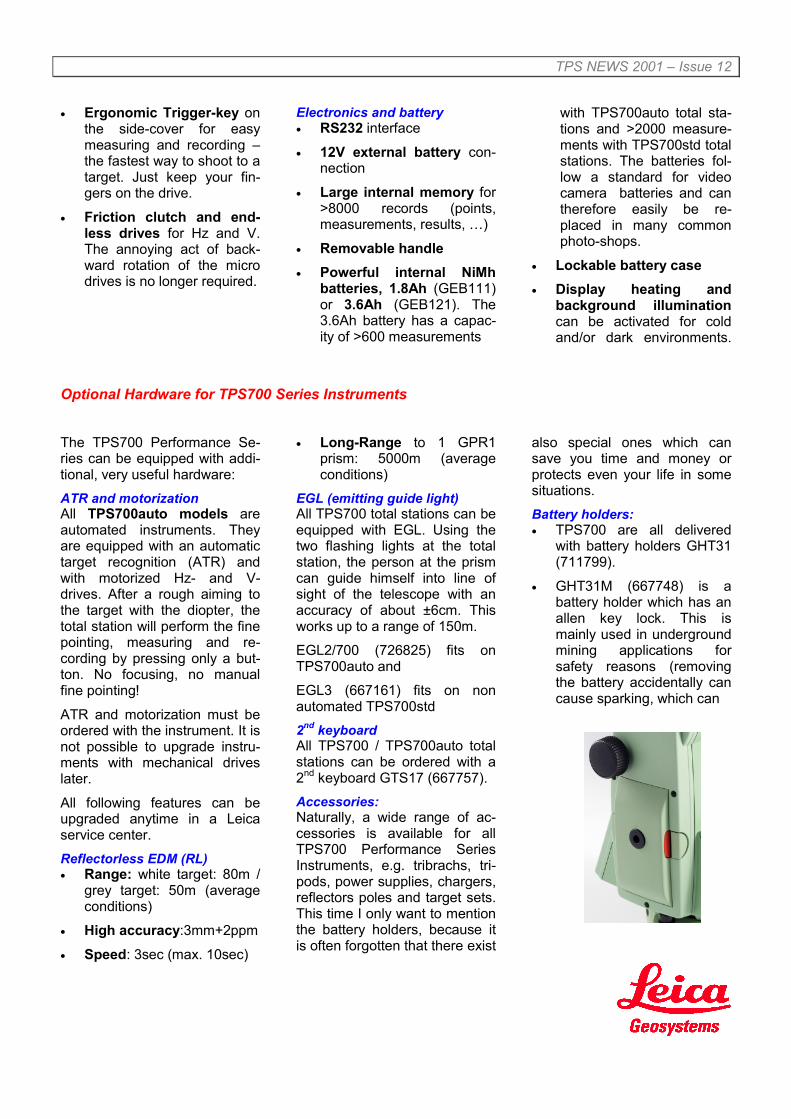
TPS NEWS 2001 – Issue 12
• Ergonomic Trigger-key onthe side-cover for easymeasuring and recording –the fastest way to shoot to atarget. Just keep your fin-gers on the drive.
• Friction clutch and end-less drives for Hz and V.The annoying act of back-ward rotation of the microdrives is no longer required.
Electronics and battery• RS232 interface
• 12V external battery con-nection
• Large internal memory for>8000 records (points,measurements, results, …)
• Removable handle• Powerful internal NiMh
batteries, 1.8Ah (GEB111)or 3.6Ah (GEB121). The3.6Ah battery has a capac-ity of >600 measurements
with TPS700auto total sta-tions and >2000 measure-ments with TPS700std totalstations. The batteries fol-low a standard for videocamera batteries and cantherefore easily be re-placed in many commonphoto-shops.
• Lockable battery case• Display heating and
background illuminationcan be activated for coldand/or dark environments.
Optional Hardware for TPS700 Series Instruments
The TPS700 Performance Se-ries can be equipped with addi-tional, very useful hardware:ATR and motorizationAll TPS700auto models areautomated instruments. Theyare equipped with an automatictarget recognition (ATR) andwith motorized Hz- and V-drives. After a rough aiming tothe target with the diopter, thetotal station will perform the finepointing, measuring and re-cording by pressing only a but-ton. No focusing, no manualfine pointing!
ATR and motorization must beordered with the instrument. It isnot possible to upgrade instru-ments with mechanical driveslater.
All following features can beupgraded anytime in a Leicaservice center.Reflectorless EDM (RL)• Range: white target: 80m /
grey target: 50m (averageconditions)
• High accuracy:3mm+2ppm
• Speed: 3sec (max. 10sec)
• Long-Range to 1 GPR1prism: 5000m (averageconditions)
EGL (emitting guide light)All TPS700 total stations can beequipped with EGL. Using thetwo flashing lights at the totalstation, the person at the prismcan guide himself into line ofsight of the telescope with anaccuracy of about ±6cm. Thisworks up to a range of 150m.
EGL2/700 (726825) fits onTPS700auto and
EGL3 (667161) fits on nonautomated TPS700std2nd keyboardAll TPS700 / TPS700auto totalstations can be ordered with a2nd keyboard GTS17 (667757).Accessories:Naturally, a wide range of ac-cessories is available for allTPS700 Performance SeriesInstruments, e.g. tribrachs, tri-pods, power supplies, chargers,reflectors poles and target sets.This time I only want to mentionthe battery holders, because itis often forgotten that there exist
also special ones which cansave you time and money orprotects even your life in somesituations.Battery holders:• TPS700 are all delivered
with battery holders GHT31(711799).
• GHT31M (667748) is abattery holder which has anallen key lock. This ismainly used in undergroundmining applications forsafety reasons (removingthe battery accidentally cancause sparking, which can

TPS NEWS 2001 – Issue 12
be very dangerous in sensi-tive environments)
• GAD39 (712156) is the redbattery adapter. Thisadapter allows to operatethe TPS700 total stationwith 6 standardLR6/AA/AM3, 1.5V batter-ies. The GAD39 fits into theGHT31 /GHT31M. Thismight be very useful as anemergency power supply,because the AA size bat-teries are available almostanywhere on the world.
Naturally the operating timefor TPS700auto instru-ments is quite limited, but itis often enough to let youfinish the job the same day.
Wolfgang
General
Moisture and SurveyEquipmentMoisture is everywhere. The airaround us has varying degreesof moisture depending on theweather conditions and whatclimatic region you are in. Sur-veyors work in extreme cli-mates, so their instrumentsmust also be able to withstandthese conditions.
Leica insists on extremely highstandards of environmentalendurance of all it's products.We place our instrumentsthrough extensive tests for thispurpose. Moisture in particularis an enemy of electronic com-ponents. This is mainly due toit's conductivity of electricity andit's ability to adversely affectelectrical pulses that occur inelectronic components. Also,once moisture has entered thehousing, it usually stays whereit can slowly corrode sensitivecomponents inside, causingproblems weeks or months afterthe initial exposure
The obvious solution you maythink is to totally seal the hous-ing of the unit. There are diffi-culties with this though. Key-boards, com ports, movingparts, and connectors for ex-ample, are difficult to properlyseal. One other problem that isnot so obvious, is the stressplaced upon seals when theoutside pressure and tem-perature changes rapidly. Thisoften happens to survey equip-ment when it is removed fromsealed carry cases.
To elaborate on this point with areal example, the RCS1100unit's design integrates sealswhich are optimized to offer thebest environmental protection tothe internal components, whileovercoming this pressure differ-ence problem. The RCS unit isnot completely sealed. We haveintegrated a special membranepermuting controlled exposureto the outside environment,which protects the unit's internalcomponents from the worsteffects of rain and immersion.This membrane will let moisture
pass through. So, in the eventof a large temperature change,moisture is permitted to con-dense upon internal compo-nents.
Our highly skilled techniciansand designers tirelessly work toensure that the RCS1100, andall our other electronic equip-ment can withstand the rigorousclimatic extremes that you, ourvalued client, call your office.
Alex
PublishingIf you have an article you would likepublished in TPS News 2002 whichmay be of interest to other readers,please contact Anna McKenzie [email protected]
The next issue of TPS News will bepublished on 28th January 2002.
Leica Geosystems AGCH-9435 Heerbrugg
(Switzerland)Phone +41 71 727 31 31
Fax +41 71 727 46 73www.leica-geosystems.com
Copyright © 2022 FDOKUMEN