Leica DMI 6000 B Modular System - Core Facilities
52
MICROSYSTEMS Leica DMI 6000 B Modular System Stands, Modules and Accessories
-
Upload
khangminh22 -
Category
Documents
-
view
0 -
download
0
Transcript of Leica DMI 6000 B Modular System - Core Facilities

M I C R O S Y S T E M S
Leica DMI 6000 BModular System
Stands, Modules and Accessories

2
Leica DMI 6000 B Modular SystemIssued: October 2004
ContentsLeica DMI 6000 B – Basic Stand page 3
Leica DMI 6000 B – Base Stand page 5
Observation and Documentation Tubes page 9
Stages and Specimen Holders page 12
Transmitted Illumination page 19
Condensers and Accessories page 20
Integrated Modulation Contrast and Integrated Positive and Negative Phase Contrast page 25
Transmitted Light Polarization Contrast page 27
Transmitted Light Differential Interference Contrast page 28
Incident Illumination for Bio-fluorescent Systems page 32
Light Sources, Lamp Housing, Supply Units page 37
TV Aadapter page 40
Objectives, Objective Turret, Optics page 41
Accessories page 45
Micromanipulator page 46
Control Units for Heating Stages and Incubators page 47
CO2 Incubation page 48
Dimensions and Weights page 49
Technical Data page 49
System Overview page 50
Published October 2004
Leica Microsystems Wetzlar GmbHErnst-Leitz-StraßeD-35578 Wetzlar (Germany)
Responsible for contents:Bernard Kleine(Marketing CM, Compound Microscopy, Product Management)Holger Grasse(Safety Officer according to MPG §30)
For questions, please contact the hotline:Tel. +49(0)6441-292286Fax +49(0)6441-292255Email: [email protected]

3
Leica DMI 6000 B – Basic StandThe Leica DMI 6000 B is a further development of Leica’s provenline of inverted research microscopes. It is designed for cellularand tissue examination, micromanipulation and microinjectiontechniques, microdissection, and confocal microscopy. The Leica DMI 6000 B is suitable for universal deployment. Allcontrast methods such as darkfield, brightfield, phase contrast,DIC, fluorescence, and modulation contrast are integral to themicroscope and can be adapted or changed quickly and easily.Variable illumination and imaging beam paths, as well as HCSoptics, modular accessories, and a comprehensive range ofperipherals complement the Leica DMI 6000 B inverted researchstand.
Basic StandThe basic stand is the solid foundation of the microscope.It includes the focusing system, objective turret, stage mount,mounts for incident and transmitted light units, an LCD screen forstatus information, and a variety of buttons for motorized func-tions such as magnification, camera ports, fluorescence andtransmitted light filters, and contrast methods. A variety ofinterfaces for PCs as well as internal and external peripheraldevices are located on the back of the basic stand.
By selecting from a range of modules such as light sources,objectives, eyepieces, tubes, stages, filters, and incident andtransmitted light components, the user can assemble a personal,application-specific microscope system.
The system diagram (see page 50) provides a good overview ofthis modular system. Leica Microsystems representatives canprovide effective support to configure an optimal system forspecific user requirements via Leica’s PC-based configurationsystem. In addition, Leica’s applications specialists can help withspecific questions.
Because of its modular design principle, the Leica DMI 6000 Bmicroscope system can be modified and extended to suitchanging requirements at any time.
Ergonomic considerations were given a high priority in all of thestand designs, such as the convenient positioning of importantcontrols and the availability of Ergomodules or ergonomiccomponent sizes.
The massive, functional, and rugged design of the stands ensureease of use and image stability over the course of the applica-tion, right up to the highest magnification.
Optics of the highest standards ensure brilliant images with highcontrast and resolution for any conceivable application.
Fig. 1: Right side of stand
Fig. 2: Left side of stand

4
Fig. 3: Leica CTR6000 electronics box
Fig. 4: Front view of stand
Fig. 5: Leica SmartMove
8 basic stands are available for the Leica DMI 6000 B. Thesebasic stands essentially differ in their options for the adaptationof integrated modulation contrast and the provisions for cameraports at the tube or the bottom of the stands.
Stand Order Number
DMI 6000 B basic stand with bottom port (ready for IMC* and top port) 11 888 284
DMI 6000 B basic stand without bottom port (ready for IMC* and top port) 11 888 285
DMI 6000 B basic stand with bottom port (without IMC* ready for top port) 11 888 286
DMI 6000 B basic stand without bottom port (without IMC* ready for top port) 11 888 287
DMI 6000 B basic stand with bottom port (ready for IMC* without top port) 11 888 288
DMI 6000 B basic stand without bottom port (ready for IMC* without top port) 11 888 289
DMI 6000 B basic stand with bottom port (without IMC* without top port) 11 888 290
Leica DMI 6000 B basic stand without bottom port(without IMC* without top port) 11 888 291
Bottom Port IMC* Top Port Order Number
x x x 11 888 284o x x 11 888 285x o x 11 888 286o o x 11 888 287x x o 11 888 288o x o 11 888 289x o o 11 888 290o o o 11 888 291
* Aavailable: May 2005
Leica CTR6000 Electronics Box (Fig. 3 p. 4)With built-in power supply 12 V 100 W, and for control of theautomatic microscope functions. With RS 232 interface for PC connection, including RS 232 cable. AC power supply 90–250 V, 50–60 Hz 11 888 109
SmartMove (Fig. 5 p. 4)x/y/z Ergo control panel for electronic focus (z) and motor stage(x/y). With 4 freely programmable function keys. 11 505 180

5
Leica DMI 6000 B – Base Stand All basic stands are ready for these contrast methods:• Brightfield• Darkfield• Phase contrast• Polarization contrast• Differential Interference Contrast (DIC)• Integrated modulation contrast (11 888 284, 11 888 285,
11 888 288, 11 888 289 only)• Integrated pos./neg. phase contrast (11 888 284,
11 888 285, 11 888 288, 11 888 289 only)• Fluorescence• Fluorescence – DIC combination contrast• Fluorescence – Phase combination contrast
All basic stands are ready for these camera connections: • Right camera port
with (100%) and/or (80%) and/or (50%) • Left camera port
with (100%) and/or (80%) and/or (50%) and/or dichroic splitting at 680 nm
• Right and left camera portwith (100%) and/or (80%) and/or (50%) and/or dichroic splitting at 680 nm
• Bottom port (11 888 284, 11 888 286, 11 888 288, 11 888 290 only)with (100%) and/or (50%) and/or (20%) and/or dichroic splitting at 680 nm(depending on right or left camera port)
• Top port (11 888 284, 11 888 285, 11 888 286, 11 888 287 only)with 100/0% and 50/50% eyepiece/port split
All basic stands are ready for these magnifications: A motorized magnification changer with 1–3 different, freely-configurable magnification levels that affect all camera ports:• 1.0x (always available)• 1.5x• 1.6x• 2.0x
Alternatives: All basic stands are ready for a manual magnification changerwith two freely configurable magnification levels. This magnifi-cation changer affects only the top port and eyepieces:• 1.0x (always available)• 1.5x• 1.6x• 2.0x
Fig. 6: Top port
Fig. 7: Schematic representation of the 6-position fluorescence disk (1), magnification changer (2), side port module (3) and bottom port module (4)

6
Controls• 7 fixed control buttons for illumination and apertures• 7 variable function buttons behind the focus controls• 3 fixed control buttons for focus steps• 2 focus hand wheels• 7 buttons for fluorescence cubes and shutters• 4 buttons for magnification changers and ports• SmartMove: Ergonomic controller for x, y, z and 4 additional
variable function buttons
Interfaces• 2 x RS232C• 2 x USB• 4 x external/internal peripherals
Objective Turret• Motorized and coded• 6x for objectives with M25 thread and 45 mm parfocal distance• For DIC: Motorized/coded Wollaston prism carousel• Anti-vibration locking
Z Focus• Motorized and coded• 9mm travel (1 mm below, 8mm above the stage)• 5 focus steps: 0.05 µm; 0.1 µm; 0.7 µm; 1.5 µm; 5.0 µm• Electronic focus repositioning• Automatic lowering prior to objective change• Electronic parfocality
Tube• Ergonomic with or without camera port at left• 2 switching positions: 100% VIS and 50% VIS/50% CAM• Optional Bertrand lens• Eye spacing adjustment• Height and angle adjustment (10° to 45°)
Optics• Leica HCS infinity optics• Tube factor 1x• 25 mm field of view
Fig. 8: Controls (left)
Fig. 9: Controls (right)
Fig. 10: Controls (front)
Fig. 11: Back panel

7
Transmitted Light Axis• Automatic illumination manager (aperture, field diaphragm,
intensity, method switching)• Automatic, color-neutral intensity control• Manual or motorized shutter• Lamp housing mount for interchangeable lamp housings• Automatic, electronic condenser identification
Incident Light Axis• Automatic illumination manager (aperture, field diaphragm,
intensity, method switching)• Automatic, color-neutral intensity control• Motorized shutter (switching speed < 50 ms)• Lamp housing mount for up to 3 interchangeable light sources• Motorized 6-position filter disk• Fluorescence Intensity Manager (FIM)
(reduction of the light intensity of incident illumination)• Mechanical booster lens for central boosting of fluorescence
or for boosting uniform distribution• Motorized Excitation Manager to monitor fluorescence
emission when using double and triple filter cubes• Ultrafast filter wheel for 3 excitation wavelengths
(switching speed < 50 ms)
Stages• Fixed regular stages
– Ceramic-coated stage plate (248mm x 204mm)– Heated stage plate (3°C above room temperature to 60 °C)– Temperature-controlled stage plate (0 °C to 60 °C)
(248 mm x 212 mm)• Fixed micromanipulation stages
– Ceramic-coated stage plate (248 mm x 204/122 mm)– Heated stage plate (3 °C above room temperature to 60 °C)
(248 mm x 204/122 mm)– Temperature-controlled stage plate (0 °C to 60 °C)
(248 mm x 204/122 mm)• Regular manual 3-plate cross-stage
– Positioning range 83 mm x 127 mm– 20 optional inserts (standard, heating, cooling) for a variety
of applications, size of inserts: 160 mm x 110 mm (compatiblewith scanning stages)
• Manual micromanipulation 3-plate cross-stage– Positioning range 40 mm x 40 mm– 3 optional inserts for a variety of applications
• Motorized micromanipulation 3-plate cross-stage– Positioning range 40 mm x 40 mm
• Scanning stage IM 120 x 100 (motors on top)– 1 mm, 2 mm, 4 mm spindle pitch (higher resolution vs. higher
speed)– 20 optional inserts (standard, heating, cooling) for a variety
of applications, size of inserts: 160 mm x 110 mm• Scanning stage IM 120 x 100 (motors on bottom)
– 1 mm, 2 mm, 4 mm spindle pitch (higher resolution vs. higherspeed)
– 20 optional inserts (standard, heating, cooling) for a varietyof applications, size of inserts: 160 mm x 110 mm
Fig. 12: Transmitted-light axis
Fig. 13: Incident-light axis illumination
Fig. 14: Micromanipulation stage with attachablemechanical stage

Screw cap for empty objective positionsComponent of stand 11 020-422-580-028
Cover for unused objective DIC disk openingComponent of stand 11 090-144-020.088
Dust and light protection cover for polarizer opening Component of stand 11 020-437-101-013
Dust and light protection cover for camera port openings Component of stand 11 020-387-556-009
Ergonomic height compensation plateA height compensation plate is available to raise the viewingheight by 20 mm or to raise the side camera ports for oversizecameras or spinning disks, or to use a microscope with aninactive bottom port on workbenches without openings.Height compensation plate: 12 mm 11 522 031Height compensation plate: 25 mm 11 522 036
Camera portsThe DMI 6000 B can be fitted with a variety of camera ports.Select the top port and/or bottom port with the selection of basicstands (see page 4). Select the side ports with the followingmodules:Motorized side port, left only 11 888 255You may select up to three different prisms from the following forthis version:• Side port prism, 100% left 11 888 259• Side port prism, dichroic 630nm left 11 888 260• Side port prism, 80% left 11 888 262• Side port prism, 50% left 11 888 264Motorized side port, right only 11 888 272You may select up to three different prisms from the following forthis version:• Side port prism, 100% right 11 888 258• Side port prism, 80% right 11 888 261• Side port prism, 50% right 11 888 263Motorized side port, right and left 11 888 273You may select up to three different prisms from the following forthis version:• Side port prism, 100% right 11 888 258• Side port prism, 100% left 11 888 259• Side port prism, dichroic 630nm left 11 888 260• Side port prism, 80% right 11 888 261• Side port prism, 80% left 11 888 262• Side port prism, 50% right 11 888 263• Side port prism, 50% left 11 888 264
8
Fig. 15: Screw cap
Fig. 16: DIC cover
Fig. 17: Analyzer opening cover
Fig. 18: Camera port cover

Observation and DocumentationTubesThe DMI 6000 B features a wide range of ergonomic tubesintegrated in the stand. The interpupillary distance can beadjusted according to the Siedentopf principle. The complex tubelens system is based on an infinite beam path. It converges theparallel beam path coming from the lens and forms the object inthe intermediate image plane. Also, the tube lens system,together with the eyepieces, corrects the remaining image errorsnot corrected by the objective.
Binocular Ergonomic TubeBinocular observation tubeSiedentopf designField number to 25 mmEyepiece diameter 30 mmInterpupillary distance range 55 mm to 75 mmVariable viewing angle 10° to 45° 11 888 277
Binocular Ergonomic Tube with Bertrand lensBinocular observation tube with Bertrand lens (for observation ofback focal plane)Siedentopf designField number to 25 mmEyepiece diameter 30 mmInterpupillary distance range 55 mm to 75 mmVariable viewing angle 10° to 45° 11 888 276
Trinocular Eergonomic TubeBinocular observation tube with side camera port and variablelight path, 100% visual/0% camera, and 50% visual/50% cameraSiedentopf designField number to 25 mmEyepiece diameter 30 mmInterpupillary distance range 55 mm to 75 mmVariable viewing angle 10° to 45° 11 888 275
Trinocular Ergonomic Tube with Bertrand lensBinocular observation tube with side camera port and variablelight path, 100% visual/0% camera, and 50% visual/50% cameraand Bertrand lens (for observation of back focal plane)Siedentopf designField number to 25 mmEyepiece diameter 30 mmInterpupillary distance range 55 mm to 75 mmVariable viewing angle 10° to 45° 11 888 253
9
Fig. 21: BinocularErgotube
Fig. 22: Siedentopf tubewith interpupil-lary distanceadjustment
Fig. 23: Trinocular Ergotube
Fig. 24: Trinocular Ergotube with Bertrand lens

Eyepieces, eyepiece adapter tubes, graticulesfor tube eyepiece
A wide range of eyepieces with 10x, 12.5x, 16x or 25x magnifica-tion (for field numbers of up to 25 mm) are available for thetubes. Special eyepieces for eyeglass wearers are available, asare eyepieces with adjustable eyelenses (M eyepieces) that aredesigned to accommodate a variety of graticules. The standardeyepiece is the 10x model; for microphotography applications12.5x eyepiece magnification is frequently preferred for greaterfocusing accuracy. This results in a smaller object field, howev-er. The eyepiece magnifications 16x and 25x are only useful forspecial situations. They may frequently exceed the "useful mag-nification" (V < 1000x objective aperture), thus resulting in a lackof sharpness. All eyepieces have removable or fold-down eye-cups and can be used with or without eyeglasses. Eyepiecesidentified with M are equipped with a focusing eyelens for diop-tric equalization (from –6.8 to +4.2 or –6 to +5) and graticuleholder.The outer diameter of the eyepiece is D = 30mm. Graticule diam-eter is D = 26mm. The eyepiece data are engraved, e.g . HCPLAN 10x/20 oo M. HC PLAN= correction type, 10x = magnifica-tion/20 = field number FOV, oo = glasses type (high exit pupil), M = dioptric adjustment/graticule holder
Oculars with FOV 20• Eyepiece HC PLAN 10x/20 BR. 11 507 801• Eyepiece HC PLAN 10x/20 BR.M 11 507 802
Eyepiece with FOV 22Eyepiece HC PLAN S 10x/22 Br.M 11 507 807
Eyepiece with FOV 25Eyepiece HC PLAN S 10x/25 Br.M 11 507 808
Special Eyepieces with High Magnification• Eyepiece HC PLAN 12.5x/16 BR. M 11 506 515• Eyepiece 16x/14B, adjustable 10 445 301 • Eyepiece 25x/9.5B, adjustable 10 445 302 • Distance ring for eyepieces 16x/14 B and
eyepiece 25x/9.5B 11 506 808
Photo Oculars, Eyepiece Tubes, Format GraticulesFor adapting microphotographic equipment, an exactly matchedcombination of photo eyepiece, eyepiece tube, and focusing andframing graticule is required. The focusing and framing graticuleis inserted into the observation eyepiece HC PLAN M and dis-plays the current photograph format. In addition, the graticulehas focusing marks for precise focusing.
10
Fig. 25: Eyepieces

11
For Photo Eyepiece 10x• Eyepiece tube HC DR 27/10x for MPS 11 541 514• Eyepiece HC 10x/16 Photo 11 541 501• Focusing and framing graticule F6, D = 26 mm 11 506 961
For Photo Eyepiece 8x• Eyepiece tube HC DR 27/8x for MPS 11 541 513 • Eyepiece HC 8x/20 Photo 11 541 500 • Focusing and framing graticule F5, 26 mm 11 506 960
For Photo Eyepiece 12.5x• Eyepiece tube HC DR 27/12.5x for MPS 11 541 515 • Eyepiece HC 12.5x/13 Photo 11 541 535• Focusing and framing graticule F8, 26 mm 11 506 963
Focusing and Framing Graticules for LengthMeasurements, Comparison, and Counting MethodsFor HC PLAN eyepieces• Graticule 10mm = 100 parts, D = 26 mm 11 506 950 • Graticule 10mm = 200 parts, D = 26 mm 11 506 951 • Crosshair graticule, D = 26 mm 11 506 953• Crosshair graticule with graduation
10mm = 100 parts, D = 26 mm 11 506 952• Graticule with grid 10 x 10 mm,
0.1 mm graduation, D = 26 mm 11 506 954• Graticule with grid 10 x 10 mm,
1 mm graduation, D = 26 mm 11 506 955• Graticule, Snyder-Graff method,
D = 26 mm (only for 10x eyepiece) 11 566 950• Graticule, ASTME 112, D = 26 mm
(only for 10x eyepiece) 11 566 951
Stage Micrometer• Transmitted light 2 mm = 200T, glass carrier with scale
1 scale interval = 10 µm 11 513 106• Incident light 10mm = 100T
for overview objectives (e.g. 1.25x) 11 519 963
Fig. 26: Photo oculars

12
Stages and Specimen HoldersA wide range of specimen stages is available. The most impor-tant are the following:
• Fixed stage (248 mm x 204 mm) normal (with and without inte-grated thermal insulation), heatable and temperature-con-trolled
• Fixed micromanipulation stage (248 mm x 112 mm) normal(with and without integrated thermal insulation), heatable, andtemperature-controlled
• Regular manual 3-plate cross-stage, positioning range 83 mm x 127 mm (with and without integrated thermal insula-tion)
• Manual micromanipulation 3-plate cross-stage, positioningrange 40 mm x 40 mm (with and without integrated thermal insulation)
• Motorized micromanipulation 3-plate cross-stage, positioningrange 40 mm x 40 mm
• Manual rotating stage• Scanning stage IM 120 x 100 (motors on top)• Scanning stage IM 120 x 100 (motors on bottom)
The 20 mm high stages are solidly attached to the microscope bythree screws. In the case of fixed stages, an attachable mechan-ical stage may be installed at the left or right (see below).
A controller is required for the heated stages. Temperaturerange: 3 °C above room temperature to 60 °C (± 0.1 °C).See the section on control units or Leica Microsystem’s separatebrochure, "Live on Stage". There you will also find further infor-mation on the differences between analog and digital controlunits.
A thermostat is required for the temperature-controlled stages.Temperature range: 0 °C above room temperature to 65 °C(– 0.1°C) depending on the coolant and thermostat used.See the section on control units or Leica Microsystem’s separatebrochure, "Live on Stage".
Fig. 27: Stage with incubator

13
Fixed Stage (248 mm x 204 mm) Regular fixed stageAluminum, ceramic-coated, extremely scratch-proof, preciselyplane-parallel, including two round 80mm inserts with 20 mm and40 mm openings.Drillings on the right and left to accommodate attachablemechanical stages; three-point mounting.Without integrated ceramic insulation on the underside of the stage 11 522 011With integrated ceramic insulation on the underside of the stage 11 522 033
Fixed Heating Stage (248 mm x 212 mm) Regular fixed heating stageTemperature range: 3 °C above room temperature to 60 °C (± 0.1 °C).One-piece stage machined from bar stock with an oval 20 x 30 mm opening. Even distribution of warmth due to lack ofseparate inserts.Usable for all electrophysiological applications due to lack ofinterference with electronics.Aluminum, black anodized, precisely plane-parallel. Drillings on the right and left to accommodate attachablemechanical stages; three-point mounting 11 522 012
Fixed Temperature-controlled Stage (248 mm x 212 mm) Regular fixed temperature-controlled stageTemperature range: 0 °C above room temperature to 65 °C(± 0.1 °C) depending on the coolant and thermostat usedOne-piece stage machined from bar stock with an oval 20 mm x 30 mm opening. Even distribution of temperature due tolack of separate inserts.Usable for all electrophysiological applications due to lack ofinterference with electronics. Circulating liquid for cooling effect.Aluminum, black anodized, precisely plane-parallel. Drillings on the right and left to accommodate attachablemechanical stages; three-point mounting 11 522 013
Stage Clamps for Regular Fixed Stage (for 11 522 011 and 11 522 033)Glass slides (76 mm x 26 mm) can be held in place with stageclamps 11 512 650
Fig. 28: Fixed stage
Fig. 29: Fixed heating stage
Fig. 30: Fixed cooling stage
14
Attachable Mechanical Stages for Regular Fixed Stages(for 11 522 011, 11 522 012 and 11 522 913)Attachable mechanical stages for all regular fixed stagesmeasuring 248 mm x >200 mm to accommodate a variety ofapplication inserts.Suitable for mounting on the left or right of the fixed stage.Positioning range: 83 mm x 127 mmErgonomic operating arm: Low position, does not interfere withmicroscope controls or camera ports, with coaxial drive for x andy. Adjustable torque, extremely precise and sensitive.Ceramic bearing surfaces in x and y.z positioning precision adjustable over the positioning range.Precise snap-in mechanism for a variety of inserts.Integrated scaling in x and y (optional for a number of inserts)
11 522 014
Inserts for Attachable Mechanical Stage 11 522 014The retaining frames are inserted into the attachable mechanicalstage via a precise snap-in mechanism. Material: Aluminum,black anodized.• Retaining frame for tissue cultures
(384 chambers) (133.5 mm x 88.5 mm) 11 520 583• Retaining frame for tissue cultures
(24 chambers) (133.5 mm x 88.5 mm) 11 520 584• Retaining frame for Terasaki plates, 60 or 72 wells 11 520 585• Retaining frame for bottles with a basic area
125 mm x 77 mm 11 520 586• Retaining frame for bottles with a basic area
82 mm x 77 mm 11 520 587 • Retaining frame for microtiter plates 96 or 120 wells 11 520 589• Retaining frame for Petri dish
dia. 88 mm / height 16 mm 11 520 590• Retaining frame for Petri dish
dia. 54 mm / height 15 mm 11 520 591• Retaining frame for Petri dish
dia. 36 mm / height 10 mm 11 520 592• Retaining frame for glass slide 76 mm x 26 mm 11 520 593• Retaining frame for Bellco test tubes dia. max. 12 mm 11 520 594• Retaining frame for plankton chamber
with a basic area (102.5 mm x 28–50.5 mm) 115 205 95• Holder with central drilling 11 520 596• Universal retaining frame M for Petri dishes
24–68 mm or glass slides 11 520 688• Universal retaining frame MX for Petri dishes
87–92 mm or multiwells 11 520 689• Universal retaining frame M-Duo for 2 Petri dishes
max. 56 mm or 1 Petri dish max. 40 plus 1 glass slide 11 531 798• Heatable universal retaining frame MH for Petri
dishes 24–68 mm or glass slides (round 35mm and oval 10 mm x 30 mm opening) 11 531 799
• Heatable universal retaining frame MH for Petri dishes 24–68 mm or glass slides (rectangular opening 47 mm x 21 mm) 11 531 817
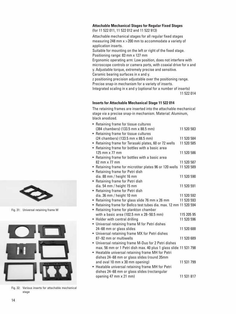
Fig. 31: Universal retaining frame M
Fig. 32: Various inserts for attachable mechanicalstage

15
Fixed Micromanipulation Stage (248 mm x 112 mm) Narrow, fixed stage for micromanipulationAluminum, ceramic-coated, extremely scratchproof, preciselyplane-parallel, including two round 80 mm inserts with 20 mmand 40 mm openings.Drillings on the right and left to accommodate attachablemechanical stages; three-point mounting.Without integrated ceramic insulation on the underside of the stage 11 522 015With integrated ceramic insulation on the underside of the stage 11 522 032
Fixed Micromanipulation Heating Stage (248 mm x 112 mm) Regular fixed heating stageTemperature range: 3 °C above room temperature to 60 °C(± 0.1 °C).One-piece stage machined from bar stock with an oval 20 mm x 30 mm opening. Even distribution of warmth due to lackof separate inserts.Usable for all electrophysiological applications due to lack ofinterference with electronics.Aluminum, black anodized, precisely plane-parallel. Drillings on the right and left to accommodate attachablemechanical stages; three-point mounting 11 522 016
Fixed Temperature-controlled Micromanipulation Stage (248 mm x 112 mm) Regular fixed temperature-controlled stageTemperature range: 0 °C above room temperature to 65 °C(± 0.1 °C) depending on the coolant and thermostat used.One-piece stage machined from bar stock with an oval 20 mm x 30 mm opening. Even distribution of temperature due tolack of separate inserts.Usable for all electrophysiological applications due to lack ofinterference with electronics. Circulating liquid for cooling effect.Aluminum, black anodized, precisely plane-parallel. Drillings on the right and left to accommodate attachablemechanical stages; three-point mounting 11 522 017
Stage Clamps for Regular Fixed Stage (for 11 522 015 and 11 522 032)Glass slides (76 mm x 26 mm) can be held in place with stageclamps 11 512 650
Fig. 33: Fixed micromanipulation stage
Fig. 35: Cooling micromanipulation stage
Fig. 34: Heating micromanipulation stage

16
Attachable Mechanical Stages for Fixed MicromanipulationStages (for 11 522 015 to 11 522 017) Attachable mechanical stages for all fixed micromanipulationstages measuring 248 mm x >112 mm to accommodate a varietyof application inserts.Suitable for mounting on the left or right of the fixed stage.Positioning range: 35 mm x 35 mm.Ergonomic operating arm, angled forward: low position, does notinterfere with microscope controls or camera ports, with coaxialdrive for x and y. Adjustable torque, extremely precise andsensitive.Ceramic bearing surfaces in x and y. 11 522 018
Inserts for Attachable Mechanical Stage 11 522 018The retaining frames are positioned and held by 2 lockingscrews. Material: Aluminum, black anodized.• Retaining frame for Petri dish dia. 30 mm 11 522 042• Retaining frame for Petri dish dia. 50 mm 11 522 043• Retaining frame for glass slide 76 mm x 26 mm 11 522 044
Regular Manual 3-plate Cross-stage Regular 3-plate stage without insertPositioning range: 83 mm x 127 mmAluminum, extremely scratch-resistant, precisely plane-parallelfor 160 mm x 110 mm inserts.Integrated receptacle for Petri dishes.Ergonomic operating arm: low position, does not interfere withmicroscope controls or camera ports, with coaxial drive for x and y. Adjustable torque, extremely precise and sensitive.Three-point mounting.Without integrated ceramic insulation on the underside of the stage 11 522 019With integrated ceramic insulation on the underside of the stage 11 522 034
Inserts for Regular Manual 3-plate Cross-stage 11 521 019 and Scanning Stages 11 522 022 and 11 522 023The retaining frames are inserted into the attachable mechanicalstage via a tension ring mechanism. Material: Aluminum, black anodized.• Insert for glass slide 76 mm x 26 mm 11 531 433• Glass stage plate with 15 mm round opening 11 522 045• Insert for microtiter plates
96 or 120 wells (tray size: 127 mm x 85 mm) 11 531 434• Insert for Terasaki plates
60 or 72 wells (tray size: 56 mm x 82 mm) 11 531 435• Insert for Hamax 60 (tray size: 93 mm x 66 mm) 11 531 436• Insert frame for Petri dish dia. 36 mm 11 531 437• Insert frame for Petri dish dia. 54 mm 11 531 438• Insert frame for Petri dish dia. 65 mm 11 531 439• Insert frame for Petri dish dia. 88.5 mm 11 531 440• Universal insert frame for Petri dishes 24–68 mm
or glass slides 11 531 441
Fig. 36: Attachable mechanical stage for micromanipulation
Fig. 37: Attachable mechanical stage for micromanipulation;a) insert for glass slidesb) insert for 30mm Petri dishesc) insert for 50mm Petri dishes
Fig. 38: Glass stage plate

17
• Universal insert frame LK for Petri dishes 24–68 mm or glass slides (with depressions at sides for micromanipulation) 11 531 818
• Universal insert frame LKX for Petri dishes 87–92 mm or multiwells 11 531 819
• Universal insert frame LK-DUO for 2 Petri dishes max. 56 mm or 1 Petri dish max. 40 plus 1 glass slide 11 531 820
• Heatable universal retaining frame LKH for Petri dishes 24–68 mm or glass slides (round 35 mm and oval 10 mm x 30 mm opening) 11 531 821
• Heatable universal insert frame LKHL for Petri dishes 24–68 mm or glass slides (rectangular opening 47 mm x 21 mm) 11 531 645
• Heating insert P with accessories. Opening dia. 32 mm, cover with glass stage plate (for DIC). Compatible with incubator S 11 531 172
• Temperature-controlled insert P with accessories. opening dia. 32 mm, cover with glass stage plate (for DIC).Compatible with incubator S 11 531 824
• Heating insert M06 for 06 multiwell plates by Falcon® No. 3072/3075 11 531 590
• Heating insert M12 for 12 multiwell plates by Falcon® No. 3047/3226 11 531 823
• Heating insert M24 for 24 multiwell plates by Falcon® No. 3043/3225 11 531 591
• Heating insert M96 for 06 multiwell plates by Falcon® No. 3046/3224 11 531 644
Slim 3-plate Cross-stage for MicromanipulationRegular 3-plate stage with two round 80 mm inserts with 20 mmand 40 mm openings.Positioning range: 40 mm x 40 mmAluminum, extremely scratch-resistant, precisely plane-parallel. Integrated receptacle for Petri dishes.Ergonomic operating arm: low position, does not interfere withmicroscope controls or camera ports, with coaxial drive for x and y. Adjustable torque, extremely precise and sensitive.Three-point mounting.• Manual
– Without integrated ceramic insulation on the underside of the stage 11 522 020
– With integrated ceramic insulation on the underside of the stage 11 522 035
• Motorized– Without integrated ceramic insulation on the underside of
the stage 11 522 021– With integrated ceramic insulation on the underside of the
stage coming soon
Fig. 39: 3-plate cross-stage
Fig. 40: Insert for 3-plate cross-stage
Fig. 41: Heating insert P
Fig. 42: Slim 3-plate cross-stage

18
Scanning Stage IM 120 x 100 3-plate Märzhäuser scanning stage without insertPositioning range: 120 mm x 100 mmThree-point mounting.Aluminum, extremely scratch-resistant, precisely plane-parallel for 160 mm x 110 mm inserts.Max. positioning speed: 10 mm/sec. to 100 mm/sec.*Max. resolution: 0.02–0.04 µm*Reproducibility: <1 µm*Precision: ± 3 µm**) Depending on spindle used: 1 mm, 2 mm or 4 mm• With motors on top 11 522 022• With motors on bottom 11 522 023
Accessories for Sscanning Stages• Inserts page 16/17• Set of cables for Märzhäuser stages 11 505 106• Cable adapter for x/y/z control 11 500 327• Control unit for scanning stage 11 505 094• SmartMove for DM/DMI series 11 505 180
Manual Rotating StageRotating stage with x/y adjustment for Petri dishes to 50 mmwith insert frame for glass slide. Positioning range: 80 mm x 80 mm, 360°.Three-point mounting.Aluminum, extremely scratch-resistant 11 521 559
Fig. 43: Scanning stage IM 120 x 100
Fig. 44: Control unit ScST
Fig. 45: Joystick for ScST
Fig. 46: SmartMove Fig. 47: Rotating stage

19
Transmitted Light IlluminationThe transmitted light illumination unit consists of an illuminationand condenser carrier. Its excellent light utilization is ensured byreplaceable Leica lamp housings and optimized asphericalcollectors. Optimal and homogeneous illumination is a precondi-tion for all transmitted light contrast methods such as phasemodulation or interference contrast.
Manual, Coded Transmitted Light Illumination ArmCompact transmitted-light illumination arm• With integrated tilting mechanism • With integrated manual field diaphragm • With integrated manual filter magazine for 2 replaceable filter
positions– One position factory-equipped with a shutter
• With condenser quick-changer• With automatic condenser identification• With standard lamp housing changer for all Leica lamp
housings• with integrated duct for lamp housing cable 11 522 026
Motorized, Coded Transmitted Light Illumination ArmCompact transmitted-light illumination arm • With integrated tilting mechanism• With integrated motorized field diaphragm • With integrated motorized filter magazine for 2 replaceable
filter positions• With integrated motorized shutter• With integrated CCIC (constant-color intensity control)• With condenser quick-changer• With automatic condenser identification• With standard lamp housing changer for all Leica lamp
housings• With integrated duct for lamp housing cable 11 522 025
Light Ffilter Diameter 40mm, Unframed for Transmitted LightIllumination Arm 2 transmitted light filters can be swung in on the manual andmotorized transmitted light illumination arms. A broad selectionof filters is available to optimize illumination for observation anddocumentation.• DLF, daylight filter 11 521 577
(blue, conversion filter e.g. for daylight film and/or visual observation)
• ALF, artificial light filter (red, correction filter for artificial light film) 11 521 578
• Panchromatic green filter 11 521 579• Neutral filter N 16 (6.3%) 11 521 579• Neutral filter N 4 (25%) 11 521 580• Neutral filter N 2 (50%) 11 521 581• VG 9, narrow band filter 11 521 583
Fig. 48: Transmitted-light illumination arm
Fig. 49: Stand with transmitted-light illuminationarm
Fig. 50: Filter magazine in illumination arm

20
Condensers and AccessoriesA variety of condensers are available for the Leica DMI 6000 B.All condensers feature a 7-position condenser disk to accommo-date light rings, IC prisms or slit diaphragms. They can beindividually equipped and are easy to use.
All condensers can be used for bright field, phase, polarization,and interference contrast.All condensers feature:
• An aperture diaphragm • A mount for interchangeable condenser heads• A mount for a polarizer• A filter mount with a diameter of 32 mm
S70/0.30 Condenser:Features a free working distance of 70 mm and a numericalaperture of 0.30 and is particularly suitable for specimens inhigh-volume containers at magnifications of up to 40x. Anauxiliary lens is swung in for magnifications of 1.25x to 5x (i.e. forlarger objects) to provide homogeneous illumination all the wayto the edge of the entire 25 mm field of view.
S28/0.55 condenser: Features a free working distance of 28mm and a numericalaperture of 0.55 and is particularly suitable for thicker specimens(living cells) for highest resolution and magnifications of up to100x. The specimens can be examined in all common dishes andtrays up to 28 mm. For micromanipulation, 5 mm more workingdistance is available than with conventional S23 condensers. In addition to the standard contrast methods, this condenser isalso suitable for dark field contrast at objective apertures of upto 0.40.Suitable inserts are available for this condenser for integratedmodulation contrast and integrated positive and negative phasecontrast.
S28/0.53 condenser: Features a free working distance of 23 mm and a numericalaperture of 0.53 and is particularly suitable for routine examina-tions of living cells, specimens for high resolutions and magnifi-cations up to 100x. The specimens can be examined in allcommon dishes and trays up to 23 mm. In addition to the standard contrast methods, this condenser isalso suitable for dark field contrast at objective apertures of upto 0.40.Suitable inserts are available for this condenser for integratedmodulation contrast and integrated positive and negative phasecontrast.
Fig. 51: S70 condenser
Fig. 52: S20 condenser
Fig. 53: S1 condenser

21
S1/0.90 and S1/1.40 Oil Condensers:Feature a free working distance of 1mm and a numerical aper-ture of 0.90 (dry) or 1.40 (oil). They are especially suited for bestresolutions and highest magnifications and resolutions inapplications that do not require large working distances, such asthe study of intracellular processes or time lapse observation.The specimens can be on glass slides or dishes. In addition tothe standard contrast methods, these condensers are alsosuitable for darkfield contrast at objective apertures of up to0.70.
For transmitted light methods, the Leica DMI 6000 B can accom-modate the full range of objectives with magnifications from1.25x to 100x. With the available condensers, specimens can beviewed in virtually any vessel.
S70 CondensersManual• Coded manual condenser including head S70/0.30 11 522 008• Light ring set for phase contrast S70/0.30 11 521 506• Manual auxiliary lens for low magnifications 11 522 024• Manual polarizer holder including polarizer 11 522 010• Wollaston prisms for DIC see page 29
Motorized• Motorized condenser including head S70/0.30 coming soon• Light ring set for phase contrast S70/0.30 11 521 506• Motorized auxiliary lens for low magnifications coming soon• Motorized polarizer holder including polarizer 11 522 009• Wollaston prisms for DIC see page 29
S28 CondensersManual with Fixed Condenser Head• Coded manual condenser base with fixed
mount for all condenser heads, S1–S28 11 522 006• Condenser head S28/0.55 11 505 175• Light ring set for PH and DF contrast S23–S28 11 521 505• Light stops for modulation contrast coming soon• Manual polarizer holder including polarizer 11 522 010• Wollaston prisms for DIC see page 29
Manual with Manually Movable Condenser Head• Coded manual condenser base with manually
movable mount for all condenser heads, S1–S28 11 522 005• Condenser head S28/0.55 11 505 175• Light ring set for PH and DF contrast S23–S28 11 521 505• Light stops for modulation contrast coming soon• Manual polarizer holder including polarizer 11 522 010• Wollaston prisms for DIC see page 29
Fig. 54: Condenser base for S1–S28
Fig. 55: S28 condenser head

22
Motorized with Fixed Condenser Head• Motorized condenser base with fixed
mount for all condenser heads, S1–S28 11 522 007• Condenser head S28/0.55 11 505 175• Light ring set for PH and DF contrast S23–S28 11 521 505• Light stops for modulation contrast coming soon• Motorized polarizer holder including polarizer 11 522 009• Wollaston prisms for DIC see page 29
Motorized with Motorized Movable Condenser Head• Motorized condenser base with motorized movable
mount for all condenser heads, S1–S28 11 522 004• Condenser head S28/0.55 11 505 175• Light ring set for PH and DF contrast S23–S28 11 521 505• Light stops for modulation contrast coming soon• Motorized polarizer holder including polarizer 11 522 009• Wollaston prisms for DIC see page 29
S23 CondensersManual with Fixed Condenser Head• Coded manual condenser base with fixed
mount for all condenser heads, S1–S28 11 522 006• Condenser head S23/0.53 11 521 500• Light ring set for PH and DF contrast S23–S28 11 521 505• Light stops for modulation contrast coming soon• Manual polarizer holder including polarizer 11 522 010• Wollaston prisms for DIC see page 29
Manual with Manually Movable Condenser Head• Coded manual condenser base with manually
movable mount for all condenser heads, S1–S28 11 522 005• Condenser head S23/0.53 11 521 500• Light ring set for PH and DF contrast S23–S28 11 521 505• Light stops for modulation contrast coming soon• Manual polarizer holder including polarizer 11 522 010• Wollaston prisms for DIC see page 29
Motorized with Fixed Condenser Head• Motorized condenser base with fixed
mount for all condenser heads, S1–S28 11 522 007• Condenser head S23/0.53 11 521 500• Light ring set for PH and DF contrast S23–S28 11 521 505• Light stops for modulation contrast coming soon• Motorized polarizer holder including polarizer 11 522 009• Wollaston prisms for DIC see page 29
Fig. 56: Condenser heads and spacer ring

23
Motorized with Motorized Movable Condenser Head• Motorized condenser base with motorized movable
mount for all condenser heads, S1–S28 11 522 004• Condenser head S23/0.53 11 521 500• Light ring set for PH and DF contrast S23–S28 11 521 505• Light stops for modulation contrast coming soon• Motorized polarizer holder including polarizer 11 522 009• Wollaston prisms for DIC see page 29
S1 Condensers (Dry)Manual with Fixed Condenser Head• Coded manual condenser base with fixed
mount for all condenser heads, S1–S28 11 522 006• Spacer ring for condenser head S1 11 521 502• Condenser head S1/0.90 dry 11 505 150• Light ring set for PH and DF contrast S1 11 521 504• Manual polarizer holder including polarizer 11 522 010• Wollaston prisms for DIC see page 29
Manual with Manually Movable Condenser Head• Coded manual condenser base with manually
movable mount for all condenser heads, S1–S28 11 522 005• Spacer ring for condenser head S1 11 521 502• Condenser head S1/0.90 dry 11 505 150• Light ring set for PH and DF contrast S1 11 521 504• Manual polarizer holder including polarizer 11 522 010• Wollaston prisms for DIC see page 29
Motorized with Fixed Condenser Head• Motorized condenser base with fixed
mount for all condenser heads, S1–S28 11 522 007• Spacer ring for condenser head S1 11 521 502• Condenser head S1/0.90 dry 11 505 150• Light ring set for PH and DF contrast S1 11 521 504• Motorized polarizer holder including polarizer 11 522 009• Wollaston prisms for DIC see page 29
Motorized with Motorized Movable Condenser Head• Motorized condenser base with motorized movable
mount for all condenser heads, S1–S28 11 522 004• Spacer ring for condenser head S1 11 521 502• Condenser head S1/0.90 dry 11 505 150• Light ring set for PH and DF contrast S1 11 521 504• Motorized polarizer holder including polarizer 11 522 009• Wollaston prisms for DIC see page 29
Fig. 57: Condenserhead S1and spacerring
Fig. 58: Spacer ring

24
S1 Condensers (Oil)Manual with Fixed Condenser Head• Coded manual condenser base with fixed
mount for all condenser heads, S1–S28 11 522 006• Spacer ring for condenser head S1 11 521 502• Condenser head S1/1.40 oil 11 551 004• Light ring set for PH and DF contrast S1 11 521 504• Manual polarizer holder including polarizer 11 522 010• Wollaston prisms for DIC see page 29
Manual with Manually Movable Condenser Head• Coded manual condenser base with manually
movable mount for all condenser heads, S1–S28 11 522 005• Spacer ring for condenser head S1 11 521 502• Condenser head S1/1.40 oil 11 551 004• Light ring set for PH and DF contrast S1 11 521 504• Manual polarizer holder including polarizer 11 522 010• Wollaston prisms for DIC see page 29
Motorized with Fixed Condenser Head• Motorized condenser base with fixed
mount for all condenser heads, S1–S28 11 522 007• Spacer ring for condenser head S1 11 521 502• Condenser head S1/1.40 oil 11 551 004• Light ring set for PH and DF contrast S1 11 521 504• Motorized polarizer holder including polarizer 11 522 009• Wollaston prisms for DIC see page 29
Motorized with Motorized Movable Condenser Head• Motorized condenser base with motorized
movable mount for all condenser heads, S1–S28 11 522 004• Spacer ring for condenser head S1 11 521 502• Condenser head S1/1.40 oil 11 551 004• Light ring set for PH and DF contrast S1 11 521 504• Motorized polarizer holder including polarizer 11 522 009• Wollaston prisms for DIC see page 29
Focusing Telescope (Bertrand Lens)A focusing telescope is required when adjusting phase contrast,modulation contrast or differential interference contrast in orderto view the rear focal plane of the objective. The following tubesare already equipped with a telescope:• Binocular ergonomic tube
with Bertrand lens 11 888 276• Trinocular ergonomic tube
with Bertrand lens 11 888 253
Focusing telescope diameter 30 mm 11 505 070
Fig. 59: Light rings
Fig. 60: Focusing telescope

25
Integrated Modulation Contrastand Integrated Positive and Negative Phase Contrast (coming soon)
Integrated modulation contrast, as well as integrated positiveand negative phase contrast are available with thefollowingstand variants:• DMI 6000 B basic stand with bottom port
(ready for IMC* and top port) 11 888 284• DMI 6000 B basic stand without bottom port
(ready for IMC* and top port) 11 888 285• DMI 6000 B basic stand with bottom port
(ready for IMC* without top port) 11 888 288• DMI 6000 B basic stand without bottom port
(ready for IMC* without top port) 11 888 289and the S23 and S28 condensers (see above).
Either an IMC/PhaCo mount or a front module which is factory-installed in the 11 888 284, 11 888 285, 11 888 288 and 11 888 289stands is required for this purpose. The IMC/PhaCo mount is anopening in the stand for the modulation contrast or phasecontrast slider. The front modules are identical, but feature anadditional magnification changer.
• Mount for integrated modulation and phase contrast 11 888 281
• Front module for integrated modulation and phase contrast and magnification changer 1.5x 11 888 283
• Front module for integrated modulation and phase contrast and magnification changer 1.6x 11 888 280
• Front module for integrated modulation and phase contrast and magnification changer 2.0x 11 888 282
The magnification changers (11 888 283, 11 888 280 and 11 888 282) affect the top camera port and are not available incombination with the motorized magnification changer (see page 34).

26
Phase contrast slider 11 522 002
Different phase rings must be placed in the contrast slider for thedifferent eyepoints of the objectives. For the eyepoints of theobjectives, please refer to the objective list (see page 42).A variety of phase rings are available for clear to milky solutions[w] or for reddish solutions [r]. In addition, a distinction is madebetween positive [+] and negative [–] phase contrast.
• Phase contrast ring PH1 (A/w/+) coming soon• Phase contrast ring PH1 (C/w/+) coming soon• Phase contrast ring PH1 (A/w/–) coming soon• Phase contrast ring PH1 (C/w/–) coming soon• Phase contrast ring PH1 (A/r/+) coming soon• Phase contrast ring PH1 (C/r/+) coming soon
Further phase contrast rings are currently being planned.For more information, please contact the hotline: [email protected]
Integrated modulation contrast slider 11 522 003
Different modulators must be placed in the modulation contrastslider for the different eyepoints of the objectives. For theeyepoints of the objectives, please refer to the objective list(see page 42). The contrast (soft or hard) and the resolution canbe adjusted to suit your personal requirements with the knurledscrews.
• Modulator A (10–20) coming soon• Modulator C (32–63) coming soon
Further modulators are currently being planned. For moreinformation, please contact the hotline: [email protected]
27
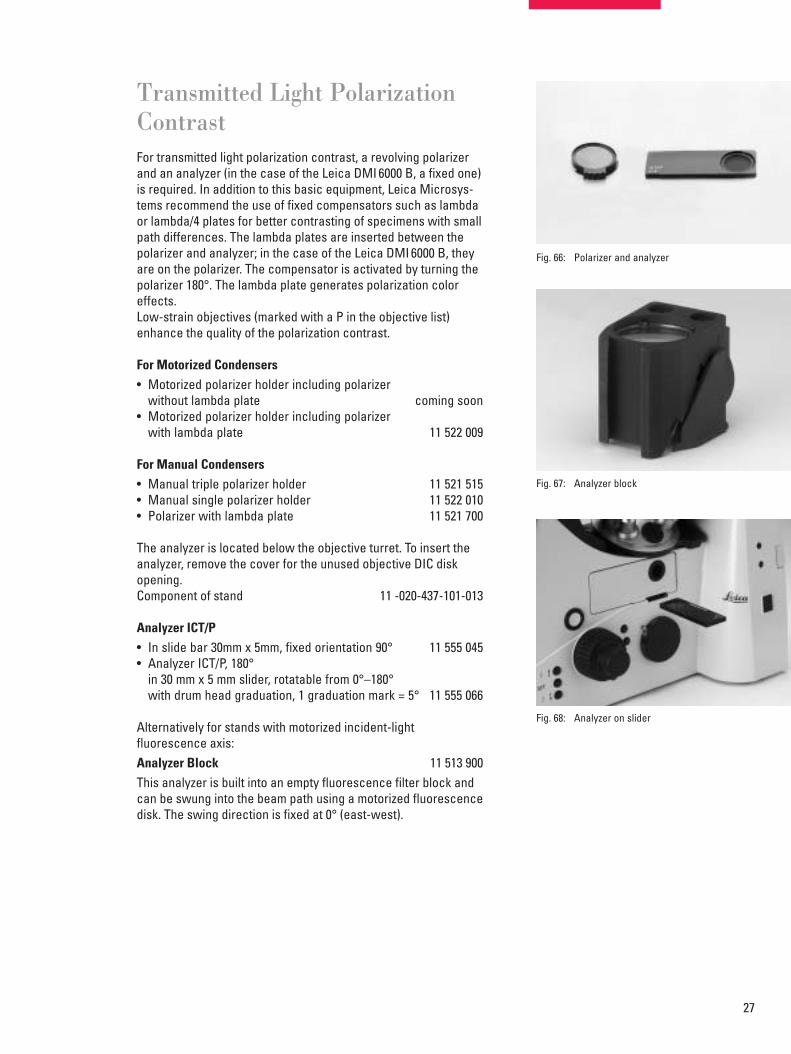
Transmitted Light PolarizationContrastFor transmitted light polarization contrast, a revolving polarizerand an analyzer (in the case of the Leica DMI 6000 B, a fixed one)is required. In addition to this basic equipment, Leica Microsys-tems recommend the use of fixed compensators such as lambdaor lambda/4 plates for better contrasting of specimens with smallpath differences. The lambda plates are inserted between thepolarizer and analyzer; in the case of the Leica DMI 6000 B, theyare on the polarizer. The compensator is activated by turning thepolarizer 180°. The lambda plate generates polarization coloreffects.Low-strain objectives (marked with a P in the objective list)enhance the quality of the polarization contrast.
For Motorized Condensers• Motorized polarizer holder including polarizer
without lambda plate coming soon• Motorized polarizer holder including polarizer
with lambda plate 11 522 009
For Manual Condensers• Manual triple polarizer holder 11 521 515• Manual single polarizer holder 11 522 010• Polarizer with lambda plate 11 521 700
The analyzer is located below the objective turret. To insert theanalyzer, remove the cover for the unused objective DIC diskopening.Component of stand 11 -020-437-101-013
Analyzer ICT/P • In slide bar 30mm x 5mm, fixed orientation 90° 11 555 045• Analyzer ICT/P, 180°
in 30 mm x 5 mm slider, rotatable from 0°–180°with drum head graduation, 1 graduation mark = 5° 11 555 066
Alternatively for stands with motorized incident-light fluorescence axis:Analyzer Block 11 513 900This analyzer is built into an empty fluorescence filter block andcan be swung into the beam path using a motorized fluorescencedisk. The swing direction is fixed at 0° (east-west).
Fig. 66: Polarizer and analyzer
Fig. 67: Analyzer block
Fig. 68: Analyzer on slider
28
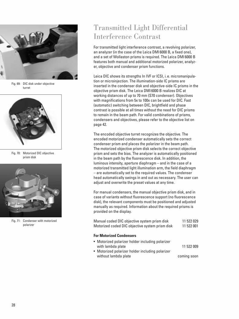
Transmitted Light DifferentialInterference ContrastFor transmitted light interference contrast, a revolving polarizer,an analyzer (in the case of the Leica DMI 6000 B, a fixed one),and a set of Wollaston prisms is required. The Leica DMI 6000 Bfeatures both manual and additional motorized polarizer, analyz-er, objective and condenser prism functions.
Leica DIC shows its strengths In IVF or ICSI, i. e. micromanipula-tion or microinjection. The illumination-side IC prisms areinserted in the condenser disk and objective-side IC prisms in theobjective prism disk. The Leica DMI 6000 B realizes DIC atworking distances of up to 70 mm (S70 condenser). Objectiveswith magnifications from 5x to 100x can be used for DIC. Fast(automatic) switching between DIC, brightfield and phasecontrast is possible at all times without the need for DIC prismsto remain in the beam path. For valid combinations of prisms,condensers and objectives, please refer to the objective list onpage 42.
The encoded objective turret recognizes the objective. Theencoded motorized condenser automatically sets the correctcondenser prism and places the polarizer in the beam path.The motorized objective prism disk selects the correct objectiveprism and sets the bias. The analyzer is automatically positionedin the beam path by the fluorescence disk. In addition, theluminous intensity, aperture diaphragm – and in the case of amotorized transmitted light illumination arm, the field diaphragm– are automatically set to the required values. The condenserhead automatically swings in and out as necessary. The user canadjust and overwrite the preset values at any time.
For manual condensers, the manual objective prism disk, and incase of variants without fluorescence support (no fluorescencedisk), the relevant components must be positioned and adjustedmanually as required. Information about the required prisms isprovided on the display.
Manual coded DIC objective system prism disk 11 522 029Motorized coded DIC objective system prism disk 11 522 001
For Motorized Condensers• Motorized polarizer holder including polarizer
with lambda plate 11 522 009• Motorized polarizer holder including polarizer
without lambda plate coming soon
Fig. 69: DIC disk under objective turret
Fig. 70: Motorized DIC objective prism disk
Fig. 71: Condenser with motorized polarizer

29
For Manual Condensers• Manual polarizer holder including polarizer
with lambda plate 11 522 010• Manual polarizer holder including polarizer
without lambda plate coming soon
The analyzer is located below the objective turret. The cover forthe objective DIC disk opening is a component of the stand.
Analyzer ICT/P In slide bar 30 mm x 5 mm, fixed orientation 90° 11 555 045
Analyzer ICT/P, 180°In slide bar 30 mm x 5 mm, revolving from 0° to 180°with drum head graduation, 1 graduation mark = 5° 11 555 066
Alternatively for stands with motorized incident light fluorescence axis Analyzer Block 11 513 900This analyzer is built into an empty fluorescence filter block andcan be swung into the beam path using a motorized fluorescencedisk. The swing direction is fixed at 0° (east-west)
Wollaston prismsObjective Prisms • IC objective prism A 11 555 006• IC objective prism C 11 555 009• IC objective prism C1 11 555 038• IC objective prism C2 11 555 039• IC objective prism D 11 555 010• IC objective prism D1 11 555 056• IC objective prism E 11 555 046
Condenser Prisms• IC condenser prism K3 11 555 017• IC condenser prism K4 11 555 018• IC condenser prism K5 11 555 019• IC condenser prism K6 11 521 521• IC condenser prism K7 11 521 522• IC condenser prism K8 11 521 523• IC condenser prism K9 11 555 030• IC condenser prism K10 11 521 524• IC condenser prism K11 11 521 529• IC condenser prism K12, oil 11 521 540• IC condenser prism K16 11 522 037
Fig. 72: DIC condenser prisms
Fig. 73: Objective prism D
Fig. 74: Analyzer block
Fig. 75: Analyzer on slider

30
Transmitted Light – Light Filters, Lambda and Lambda/4 PlateD = 32 mm in holder with handle. For insertion in • Triple filterholder 11 512 515Mount above the manual condenser.
• DLF, daylight filter (blue, conversion filter for daylight film and visual observation) 11 514 753
• ALF, artificial light filter (red, correction filter for artificial light film) 11 514 754
• Panchromatic green filter for black/white photography 11 512 077
• VG 9, green filter for contrast enhancement (B/W) 11 563 122
• IL 546 nm (Polarization microscopy, interferometry) 11 563 155
• Neutral filter N2 (50%), in holder 11 543 092
• Neutral filter N4 (25%) 11 543 093
• Neutral filter N16 (6.3%) 11 543 184
• Neutral filter N16 (6.3% oblique) 11 514 752
• Polarizer 11 505 087
• Lambda plate (λ) 11 513 908
• Quarter lambda plate (λ/4) 11 513 570
• Polarizer with protective filter 11 513 711
Fig. 76: Filter with handle

31
Transmitted Light Filter d = 32mmWithout holder, to be placed loosely on the condenser.
• DLF, daylight filterBlue conversion filter for daylight film and visual observation 11 504 046
• ALF, artificial light filterRed, color correction filter for artificial light film 11 504 047
• Panchromatic green filterFor B/W photography and sensitivity enhancement of the eye 11 504 011
• Green filter VG 9For B/W photography and sensitivity enhancement of the eye 11 504 004
• Neutral gray filter N166.3% transmission 11 504 005
• Neutral gray filter N425% transmission 11 504 006
• Neutral gray filter N250% transmission 11 504 007
• Neutral gray filter N1.470% transmission 11 504 008
• Diffusion filter N 11 504 012
• Interference green filter VSS 546for monochromatic light 11 504 010
• Blue glass filter BG 20Color contrast filter for Polaroid color photos and general contrast enhancement 11 504 009
Fig. 77: Transmitted-light filter

32
Incident Illumination forBio-fluorescent Systems The incident light fluorescence of the Leica DMI 6000 B featuresa completely new incident illumination system. The newlydeveloped 1" illumination axis is designed for a variety of lightsources. Optimal light flux with the greatest intensity and homo-geneity is guaranteed. Light traps and the suppression of naturalfluorescence result in an optimal black background.A variety of lamp mounts and mirror housings (up to 3 ports) alsopermit simultaneous use of multiple light sources.
The regular incident fluorescence illumination is based on high-intensity high-pressure 100 W mercury burners (Hg 100 W) withemission in the short-wave spectral range. Furthermore, xenonlamps (XE 75 W) are used when a broadband spectrum range isto be covered.
The excitation of the specimen is controlled by the FIM (Fluores-cence Intensity Manager) method of decreasing light intensity in5 increments for equalization of brightness levels for specimenswith multiple dyes.
A centerable field diaphragm and 12 different aperturediaphragms that can be selected freely using the FluorescenceIntensity Manager ensure optimal Koehler illumination. Theresult is the best possible resolution, contrast and depth of field.
The incident light axis is equipped with an automatic light stop,which is activated at the touch of a button or via software toprevent specimens fading.
Depending on the application, a switchable auxiliary lens(booster) provides either maximum fluorescence intensity(factor: 1.4x in 75% center of field) or optimal homogeneity andbrightness distribution (factor: 0.7x for the entire field).
The ultrafast filter changer supports switching between up tothree different excitation wavelengths within 50 ms. This permitsextremely fast switching between different emissions withoutmoving filter blocks when using a dual or triple filter block (seebelow).
Fig. 78: Fluorescence drawer
Fig. 79: Fluorescence module (installed)
Fig. 80: FIM and internal filter wheel

33
The Excitation Manager is available together with the ultrafastfilter changer. It supports the tuning of emissions over 15 stages,two excitation wavelengths and a variety of intensities and themixing of various colors.
Up to 6 fluorescence filter blocks on the disk contain an optimalcombination of excitation, reflection, splitter, bandpass andblocking filters. The disk is integrated in the stand and is fullymotorized and coded. Filter blocks can be switched in less than0.2 sec.
A locking button releases the disk in a drawer for easy, convenient filter replacement within seconds, without tools.
The filter systems (blocks) have spring clamps for clicking intothe incident light nosepiece. All blocks are designed to ensurezero pixel shift and completely suppress stray light to provide acompletely black background for the fluorescent image.
All relevant blocks are equipped with a red absorption filter BG38for contrast enhancement.
Incident and transmitted light can be used simultaneously for theoptimal identification of fluorescent and non-fluorescent struc-tures.
An adjusting window on the side permits the optimum setup ofthe lamp using the included adjusting aid.
Fig. 81: Fluorescence block A4
Fig. 82: Opening the drawer
Fig. 83: Fluorescence module

34
Motorized Fluorescence System andMotorized Magnification Changer
The optional motorized magnification changer is located on thefluorescence disk. In addition to the 1x tube lens, two furthermagnification levels can be introduced on an additional disk with3 positions. The motorized magnification changer affects allcamera ports. The magnification changer on the front modulecannot be used at the same time.
Motorized 6-position Fluorescence Disk• With Fluorescence Intensity Manager (FIM)• With internat fast filter wheel (IFW) and Excitation Manager• With motorized magnification changer
including 1x tube lens at position 1 11 888 300
Motorized 6-position Fluorescence Disk• With Fluorescence Intensity Manager (FIM)• With motorized magnification changer
including 1x tube lens at position 1 11 888 266
Motorized 6-position Fluorescence Disk• With Fluorescence Intensity Manager (FIM)• With internal fast filter wheel (IFW) and Excitation Manager
including fixed 1x tube lens 11 888 301
Motorized 6-position fluorescence disk• With Fluorescence Intensity Manager (FIM)
including fixed 1x tube lens 11 888 267
Variants Without Incident Light Fluorescence:Motorized Magnification Changer• Including 1x tube lens at position 1 11 888 269
Fixed 1x tube lens 11 888 268
Magnification levels for motorized magnification changer
In addition to the 1x tube lens, one or two lenses can be installedon the disk.
• 1.5x tube lensfor motorized magnification changer 11 888 689
• 1.6x tube lensfor motorized magnification changer 11 888 265
• 2.0x tube lensfor motorized magnification changer 11 888 690
Fig. 84: 6-position fluorescence disk and motorized magnification changer
Fig. 85: 6-position fluorescence disk and motorized magnification changer

35
Lamp Mount for Lamp Housings (and Fibre Optic orLaser Couplings)
Lamp Mountfor one lamp housing or one fiber optic or laser couplingErgonomically angled 90° to the right for optimal adjustment of L lamp housings 11 504 110
Lamp Mount for one lamp housing, or a fiber optic or laser couplingUnder 0° for straight coupling and when using incubator ML 11 504 111
Manual Mirror Housing to accommodate two light sources, or fiber optic or laser couplingsErgonomically angled 90° to the right for optimal adjustment of L lamp housings and a straight position 11 504 108
Manual Mirror Housing to accommodate two light sources, or fiber optic or laser couplingsErgonomically angled 90° to the left for optimal adjustment of regular lamp housings and a straight position 11 504 109
Motorized Mirror Housing to accommodate 3 light sources, or fiber optic or laser couplingsErgonomically angled 90° to the left and right for optimal adjustment of all Leica lamp housings and a straight position 11 504 107
Booster LensDepending on the application, a 180° turn of the switchableauxiliary lens (booster) provides either maximum fluorescenceintensity (factor: 1.4x in 75% center of field) or optimal homo-geneity and brightness distribution (factor: 0.7x for the entirefield).Suitable for insertion into the stand on the right or left, depending on order. 11 522 027
Fig. 86: Rear view of stand with lamp mount
Fig. 87: Booster lens
36
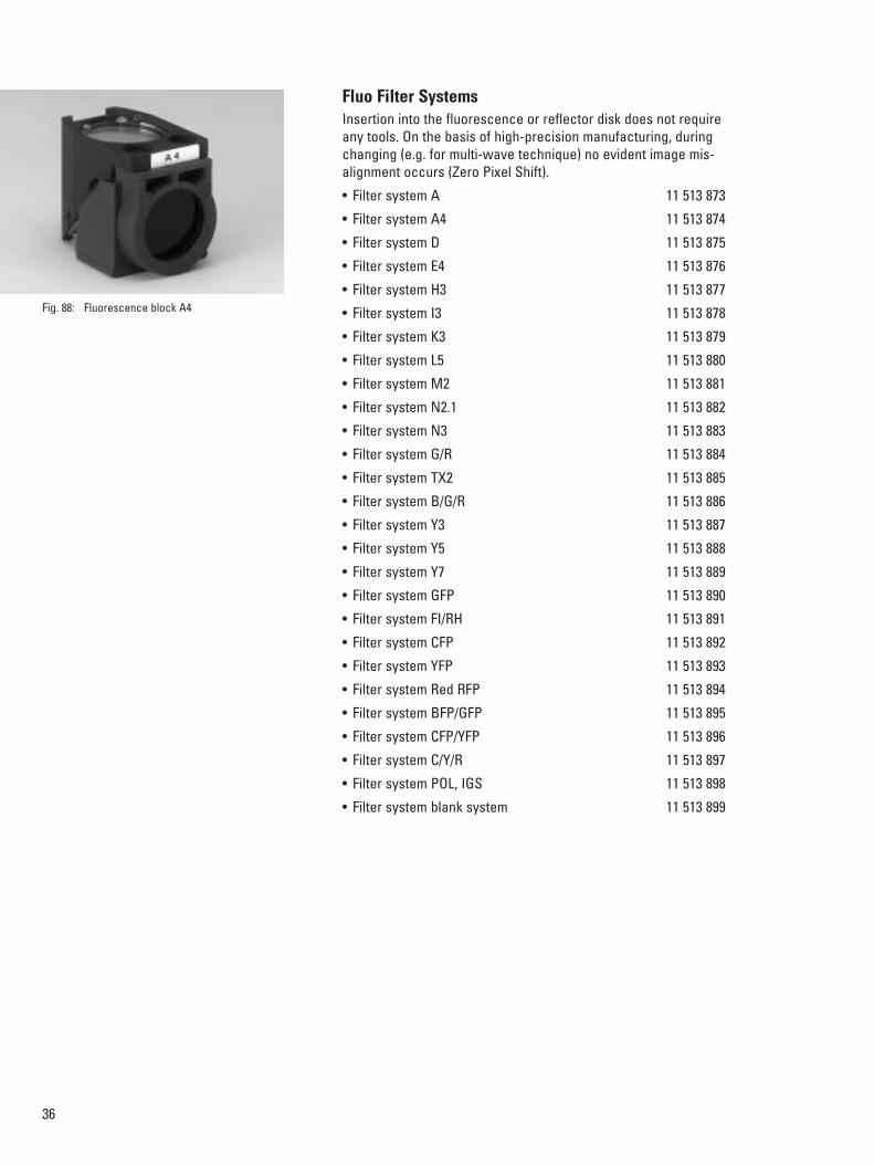
Fluo Filter SystemsInsertion into the fluorescence or reflector disk does not requireany tools. On the basis of high-precision manufacturing, duringchanging (e.g. for multi-wave technique) no evident image mis-alignment occurs (Zero Pixel Shift).
• Filter system A 11 513 873
• Filter system A4 11 513 874
• Filter system D 11 513 875
• Filter system E4 11 513 876
• Filter system H3 11 513 877
• Filter system I3 11 513 878
• Filter system K3 11 513 879
• Filter system L5 11 513 880
• Filter system M2 11 513 881
• Filter system N2.1 11 513 882
• Filter system N3 11 513 883
• Filter system G/R 11 513 884
• Filter system TX2 11 513 885
• Filter system B/G/R 11 513 886
• Filter system Y3 11 513 887
• Filter system Y5 11 513 888
• Filter system Y7 11 513 889
• Filter system GFP 11 513 890
• Filter system FI/RH 11 513 891
• Filter system CFP 11 513 892
• Filter system YFP 11 513 893
• Filter system Red RFP 11 513 894
• Filter system BFP/GFP 11 513 895
• Filter system CFP/YFP 11 513 896
• Filter system C/Y/R 11 513 897
• Filter system POL, IGS 11 513 898
• Filter system blank system 11 513 899
Fig. 88: Fluorescence block A4

37
Light Ssources, Lamp Housing, Supply UnitsThe light sources are housed in lamp mounts, which are housedin lamp housings. The lamp housings are fastened to the standor transmitted light illumination arm using a flange ring.This allows optimum heat decoupling and comfortable handling.The following equipment is available:
For Transmitted Light:
Standard Lamp HousingLamp Housing 107/2 (Single-lens)Plastic lamp housing with lamp access from above.With fixed, pre-centered lamp mount with 0.70 m power cableincluding 1x halogen bulb 12 V 100 W, single-lens aspherical,permanently set collector, heat-absorbing filter, microprism griddisk with middle diffuser for enlargement of the lamp filamentand optimization of the illuminated area, without reflector, without replacement lamp. 11 504 104
Lamp Housing 107/2 (Single-lens)as above, but with 2.5 m power cable 11 504 103
Lamp Housing 107, Left-hand Operation (Double-lens)Plastic lamp housing with lamp access from above.With centerable lamp mount with 0.70 m power cable including1x halogen bulb 12 V 100 W, double-lens aspherical, focusablecollector, heat-absorbing filter, microprism with middle diffuserfor enlargement of the lamp filament and optimization of the illuminated area, without reflector, without replacement lamp.
11 504 102
Lamp Housing 107, Left-hand Operation (Double-lens)as above, but with 2.5 m power cable 11 504 101
Lamp Housing 106 (Double-lens)Metal lamp housing with side lamp access. With centerable lamp mount with 0.70 m power cable including1x halogen bulb 12 V 100 W, double-lens aspherical, focusablecollector, heat-absorbing filter, microprism with middle diffuserfor enlargement of the lamp filament and optimization of theilluminated area, without reflector, without replacement lamp.
11 504 058
Lamp Housing 106 (Double-lens)as above, but with 2.5 m power cable 11 504 059
Fig. 90: Lamp housing 107 (double-lens)
Fig. 89: Lamp housing 107/2 (single-lens)
Fig. 91: Lamp housing 106 (double-lens)

38
Lamp Housing 106z, Left-Hand Operation – 12 V 100 W (4-lens)Metal lamp housing with side lamp access.With centerable lamp mount with 0.70 m power cable including1x halogen bulb 12 V 100 W, four-lens, achromatic, focusablecollector, centerable reflector for doubling of the lamp filamentand optimization of the illuminated area, with heat-absorbing filter, without auxiliary lamp. 11 504 091
Lamp Housing 106z – 12 V 100 W (4 lens)As 11 504 091, but right-hand operation. 11 504 070
For Incident Light (Fluorescence):
Lamp Housing 106z, Left-hand Operation – Hg 100 W (6-lens)Metal lamp housing with side lamp access. Left-hand operationfor DMI 6000 B.With centerable lamp mount for Hg 100 W lamp with 1.5 m power cable. 6-lens, achromatic 1-inch collector, UV-optimized transmission> 50% at 340 nm, centerable reflector for doubling the focal pointand optimization of the illuminated area, with heat-absorbing filter, without burner. 11 504 106
Lamp Housing 106z– Hg 100 W (6-lens)As 11 504 106, but right-hand operation. 11 504 114
Lamp Housing 106z – Xe 75 W (6-lens)Metal lamp housing with side lamp access.With centerable lamp mount for Xe 75 W lamp with 1.5 m powercable.6-lens, achromatic 1-inch collector, UV-optimized transmission> 50% at 340 nm, centerable reflector for doubling the focal pointand optimization of the illuminated area, with heat-absorbing fil-ter, face protection, protective gloves, without burner. 11 504 105
Fiber Optic CouplingA fiber optic coupling can be inserted between the lamp mountand lamp housing. This "cold" light source prevents the standfrom warming up and is also useful in conjunction with large climate chambers.• Fiber optic coupling, complete with 1 m light guide 11 504 112• Fiber optic coupling, complete with 2 m light guide 11 504 113
Fig. 92: Lamp housing 106z – 12 V 100 W (4 lens)
Fig. 93: Halogen bulb 12 V, 100 Wfor lamp housing 106z
Fig. 94: Lamp mount for Hg 50 W
Fig. 95: Lamp mount for Hg 100 W

39
Lamps and Burners• Halogen bulb 12 V 100 W (Fig. 93 p. 38) 11 500 974• High-pressure mercury burner Hg 100 W
(Fig. 95 p. 38) 11 500 138 • High-pressure mercury burner Hg 100 W/2
(longer life) 11 500 321• High-pressure xenon burner Xe 75 W 11 500 139
Spacer for Filter D = 50mm2 filter positions at LH 106/107, 4 filter positions with LH 106 z. adapter between LH. 11 505 030
Additionally, for Xe 75 W lamp:Gray Filter 0.2%D = 50 mm, 0.2% transparency, in holder 11 514 031
Diffusion Filter ND = 50 mm, embossed, in holder. 11 514 042
Additional filters D = 50mm in holder:• DLF, daylight filter 11 514 755• ALF, artificial light filter 11 514 756• Panchromatic green filter 11 542 131• VG 9, green filter 11 514 041• Neutral gray filter N20 (5%) 11 514 036• Heat-absorbing filter 11 514 027
Supply Units
For power supply voltages other than 220–240 V, the following isrequired:Pre-transformer 100–120 V With power supply cord, primary 100–120 V, secondary 220–230 V 11 500 316
Supply Unit Hg 100 WWith power supply cord, automatic switching to power supplyvoltage 90 V–250 V 50/60 Hz with operating hours display.
11 500 325
Supply Unit Xe 75 W With power supply cord, automatic switching to power supplyvoltage 90 V–250 V 50/60 Hz with operating hours display.
11 500 324
Fig. 96: Filter and spacerfor filter d = 50mm
Fig. 97: Polarizer protective filter
Fig. 98: Supply unit Hg 100 W

40
TV AdapterYou can adapt analog and digital cameras to all tubes with docu-mentation output. The C-B and F-mount adapters are aligned tothe dimensions of the holder thread. The various fixed and vari-able magnification factors allow adjustment of the rendering ofthe microscopic image on the camera chip. In order to displaythe largest possible portion of the field of view on the monitor,the magnification factor of the adapter must fit the chip size ofthe camera. If the magnification is too low, there will be a lack ofuniformity to the illuminated area (shading) and/or vignetting.
Diagonal measurements of images taken (in mm) at
1 inch- 2/3 inch- 1/2 inch- 1/3 inch- Order No.Camera Camera Camera Camera
Without variable magnification, only for single chip cameras:C-mount adapter 1x HC 16 11 8 6 11 541 510C-mount adapter 0.63x HC – 17.5 12.7 9.5 11 541 537C-mount adapter 0.5x HC – – 16 19 11 541 511C-mount adapter 0.35x HC – – – 17.1 11 541 512
With variable magnification (Vario TV adapter) for 1–3 chip cameras:C-mount, 0.32–1.6x HC – – 19*–5 18–3.8 11 541 517B-mount (ENG), 0.5–2.4x HC (1/2 inch) – – 16–3.3 – 11 541 518
Without variable magnification level, only for 1-3 chip cameras:C-mount adapter 1x – – 16 12 11 543 706B-mount adapter 1x – – 16 12 11 543 702B-mount adapter 1.25x – 17.5 – – 11 541 539F-mount adapter 1x – – 16 12 11 541 540F-mount adapter 1.25x – 17.5 – – 11 541 541Required for each: TV optics 0.5x HC 11 541 538
* Available beginning with Vario factor 0.42x!
Fig. 101: TV adapter
Fig. 102: TV adapter
Fig. 103:C-mount 0.63x HC
Fig. 103:C-mount 0.5x HC

41
Objectives, Objective Turret,Optics ObjectivesBased on the Leica principle of infinity distance correction ofoptics, the microscope objectives are infinity corrected for tubelens systems with 200 mm reference focal lengths. The calibra-tion length is 45 mm for bright field.The objectives are divided into 4 correction classes:• Achromatic objectives: C PLAN
Field of view performance up to FOV 20• Planachromatic objectives: N PLAN
Field of view performance up to FOV 22• Semi-apochromatic objectives: HC/X PL FLUOTAR
Field of view performance up to FOV 25• Apochromatic objectives HC/X PL APO
Field of view performance up to FOV 25When selecting the objectives, consider the intended use withregard to specimen covering, etc. For more detailed explana-tions, please refer to the appendix of the objective list.
Objective TurretIn principle, all infinity corrected high-performance Leicaobjectives with an M25 thread may be used. Even older objec-tives can be adapted for further use. An adapter is available forRMS-threaded objectives:• Adapter M25/RMS 11 506 028• Adapter M32/M25 11 561 003• Adapter M32/RMS 11 562 281A wide range of application objectives with long working distances (L objectives) and/or with corrective mounts (Corrobjectives) are available especially for inverted microscopy.The following table lists all objectives of the Leica program.The specimen is focused via the 6-position M25 objective turret.The reliable, stable and precise focusing is not affected by thestage and its specimens or accessories. Adapters are available for the installation of objectives withdifferent thread sizes. Objectives of earlier lines with RMSthreads cannot be adapted unconditionally, however, as problems with parfocality and field flattening may arise.
OpticsThe optics are the heart of every microscope and influence thequality of the image information. Leica has set standards in thisrespect with the introduction of HC optics. Eyepieces, tubelenses, and objectives have been carefully harmonized with oneanother.
Fig. 104: HCX PL Fluotar 63x/0.90 Corr
Fig. 105: Objective turret
Fig. 106: Adapter for RMS-threaded objectives

42
Leica HCS Objectives, Version 3.8

43

44
IC prisms for interference contrast:Condenser prisms:K1a only DM R with condensers UCR/UCPR,
condenser head swung out K1b only with DM4000, DM4500, DM5000, DM6000 condensers,
condenser head swung out K2 – K5 + K11 only with condenser head 0.90 S1 or P 0.90 S1
(upright)K9, K12, K15 only with condenser head P 1.40 OIL S1Objective prisms: A – EPrisms B2/D for wider splitting = higher contrast
B1/D1 for narrower splitting = higher resolution
Cover glass requirements:– can be used with and without cover glassO for use without cover glass0.17 for use with cover glass 0.17mm (DIN/ISO) 1.8 Q with quartz glass window 1.8mm, for use on heating stages 0 – 2 can be used with cover glasses from 0 – 2mm thick
Weakest objective magnification levels:According to microscope/condenser type:DM LS/LSP 4x/FOV 20; 5x/FOV 25UCL/UCLP 2.5x/FOV 25 with auxiliary lens 2.5CL/PH 2.5x with diffusion filterDM LB/LP/LM 4x/FOV 20 or 5x/FOV 25UCA/UCAP 1.6x/FOV 25DM R series 1.6x all FOV (UCR/UCE/UCPR)approx. 1x with Bertrand lens B (without objective) and special condenser
1) With quartz plate for enhanced contrast (crossed polarizers required)
2) Inert front section with minimal electrical and thermal conductivity, chemically neutral ceramics3) Immersion cap for oil, water etc. available (11 556 045)4) Capping piece CG 0.4 (11 506 071) for cover glass 0.25 – 0.55mm5) For low-contrast incident light objectives alternative objectives N PLAN POL or
HC PL FLUOTAR/PL APO6) K1a condenser prisms only with condenser UCR/stands DM R, condenser head swung out!7) Correction for adjustment with/without cover glass/with water, glycerol, immersion oil8) Correction for adaptation to cover glass thicknesses 0.14 – 0.18mm/
temperature 15 – 37 °C/NaCI content 0 – 3 %9) Correction for temperature 15–37 °C and NaCl 0–3 %
11) With condenser head P 1.40 OIL S112) U-V-I: UV-Visible-IR13) Appropriate and recommended for Leica Integrated Modulation Contrast (IMC)14) Optimized for Confocal Scanning15) Lbd. Bl (Lambda Blue): GFP optimized16) With piezo focus drive (Leica AS MDW)17) Recommended for Leica DM 4000, DM 5000, DM6000
Adapters are required for objective threads that do not match the turret:M25/RMS 11 506 028 M32/M25 11 561 003 M32/RMS 11 562 281
Tube length ∞, Reference focal length tube length fB = 200mm, calibration length 45mm
Immersions:OIL = immersion oil as per DIN/ISOIMM = water, glycerin or oilW = water
Methods:Suitable for transmitted light bright field, transmitted light darkfield, fluorescence and polarization contrast; no special labeling. Achromatic objectives C PLAN are only conditionally recommended forfluorescence.BD = for brightfield/incident light-dark fieldPH = phase contrast objectiveRC = reflection contrast objectiveL = long working distanceP, POL = low-strain, for quantitative polarization/
=not for incident light, with exception of fluorescenceLMC = modulation contrast objective (only with DM IRB)

45
AccessoriesImmersion oil, 20 mlas per ISO 8036/1, refraction index ne
23 = 1.5180 ± 0.005, dispersion ve
23 = 44 ± 2 11 513 860
Immersion oil, 250 mlas per ISO 8036/1, refraction index ne
23 = 1.5180 ± 0.005, dispersion ve
23 = 44 ± 2 11 513 861
Immersion oil, 10 mlFree of natural fluorescence as per ISO 8036/1, refraction index ne
23 = 1.5180 ± 0.005, dispersion ve
23 = 44 ± 2 11 513 859
Stage micrometerTransmitted light 2 mm = 200 parts 11 513 106
Stage micrometerIncident light 1 mm = 100 parts 11 563 011
Focusing telescope diameter 30.0mm 11 505 070
Halogen lamp 12 V 100 W 11 500 974
Hg 50 W burner 11 500 137
Hg 100 W/2 burner 11 500 321
Xe high-pressure burner 11 500 139
Digital Image Documentation and Analysis
• Leica Digital Camera System DC150, DC180, DC300/350DC480, DC500, D2DV3
Monochrome and color digital cameras for all requirementsbetween highest resolution (12 megapixels) and quick live image(25 frames per second)(see Leica Digital Camera brochures)
Leica Image Analysis Systems:• Leica CW4000
Image analysis for cytogenetics• Leica Qprodit
Image analysis for pathology• Leica FW4000
Fluorescence imaging solutions• Leica Q550MW
Image analysis for materials testing(see Leica Image Analysis brochures)
Fig. 107: Proper handling of Hg burner
Fig. 108: Proper handling of halogen lamp

46
MicromanipulatorMechanical micromanipulators are also available for all invertedLeica microscopes:
• Micromanipulator (for right side of microscope) 11 520 137• Micromanipulator (for left side of microscope) 11 520 138
• Massive baseplatefor the assembly of the microscope and micromanipulator 11 522 040
• Extension for DMI 6000 B 11 521 630• Single instrument holder 11 520 142• Dual instrument holder 11 520 143• 3 Instrument sleeves 11 520 145• 100 glass tubes (diameter 1mm)
for pipettes 11 520 119
While other micromanipulation accessories such as microtools,pullers, grinders, microforges and anti-vibration tables are notpart of the Leica program, they can be supplied by your Leicadistributor on request.
Information can also be provided on the adaptation of non-Leicamicromanipulation tools for in-vitro fertilization, microinjection,microdissection or patch clamping.
Fig. 109: Micromanipulator with extension and single instrument holder

47
Control Units for Heating Stages and IncubatorsA broad range of control units are required for heating stages,objective heaters and incubators. Leica supplies a variety oftypes depending on the number of components to be heated. For a detailed description and sample applications, please seeLeica Microsystem’s "Live on Stage" brochure.
TempControl MiniFor objective heater temperature control. Control range35°C–40 °C • For 115 volts 11 532 310• For 230 volts 11 531 826
TempControl 37 (1-channel)For temperature control of a single component. Suitable forobjective heaters, heating stages or heating inserts(see pages 14 and 17). Control range: 3 °C above room temperature to max. 60 °C • For 115 volts 11 532 309• For 230 volts 11 521 721
TempControl 37-2 (2-channel)For temperature control of two components. Suitable for objective heaters, heating stages, heating inserts or CTI controllers (see pages 14 and 17).Control range: 3 °C above room temperature to max. 60 °C • For 115 volts 11 532 308• For 230 volts 11 521 719
Heating UnitHeater to warm air for the incubator ML. Also usable for otherincubators when using air rather than CO2. A TempControl 37-2unit is always required, however.3 heating stages7 ventilation stages• For 115 volts 11 532 306• For 230 volts 11 531 833
CTI Controller 3700C02 control unit (concentration and circulation) and temperaturecontrol CO2 range: 0–7.5% ± 0.1%Circulation: 5 stagesTemperature stability: ± 0.1 °CRS232 interface• For 115 volts 11 521 591• For 230 volts 11 521 588
Fig. 110: TempControl Mini
Fig. 111: TempControl 37
Fig. 112: TempControl 37-2 digital
Fig. 113: Heating unit
Fig. 114: CTI controller 3700

48
CO2 Incubation A variety of incubators are available depending on the applica-tion and features of the inverted microscope.Incubators are used whenever living cells are to be observedunder physiological conditions. For a detailed description and sample applications, please seeLeica Microsystem’s "Live on Stage" brochure.
Incubator SIncubator for heating insert P (11 531 172), for use on regular 3-plate cross-stages and scanning stages. 11 531 171
Incubator S-MIncubator for the heating inserts M06–M96 (11 531 590, 11 531 823, 11 531 591, 11 531 172),for use on regular 3-plate cross-stages and scanning stages. 11 531 589
Incubator LIncubator for fixed stages, unheated or heatable, with or without attachable mechanical stage. 11 521 587
Incubator MLIncubator for the entire microscope 11 521 749
CO2 ControllerIn combination with incubator ML instead of CTI controller• For 115 volts 11 532 305• For 230 volts 11 521 733
Further accessories can be found in Leica's applicationbrochure, "Live on Stage" for the following:• pH value monitoring, e.g. covers for heating inserts, acces-
sories for • Stage cooling such as thermostats, O2 monitoring
systems • Evaporation control systems or cell incubation
systems (POC chambers)
Fig. 115: Incubator S
Fig. 116: CO2 controller
Fig. 117: POCmini
Fig. 118: POC-R

49
Dimensions and Weights
Weights:Leica DMI 6000 B transmitted light configura-tion, complete with lamp housing and tube
approximately 21 kg
Leica DMI 6000 B incident/transmitted lightequipment, complete with lamp housing andtube approx. 27 kg
Technical Data
Operating voltage: 90–250VFrequency: 50/60 HzPower consumption: P max: 180 WOperating temperature: 10 °C–36 °CRelative humidity: 0–80% at 30 °C
623 mm
665
mm
410–
510
mm
265
mm
126 mm
268 mm 151 mm

System Overview Leica DMI6000 B
0.5x
Leica DC150
Leica DC180
Leica DFC280
Leica D(F)C300 (F/X)
0,5–
2,4x
0,33
–1,6
x
0,35
x
0,5x
0,63
x
1x
11 5
41 5
18
11 5
41 5
17
11 5
41 5
12
11 5
41 5
38
11 5
41 5
11
11 5
41 5
37
11 5
41 5
10
11 541 540F-mount
1/2
11 541 541F-mount
2/3
11 543 706C-mount
1/2
11 543 702B-mount
1/2 Sony
11 541 539B-mount
2/3 Sony
1x1x 1x1.25x 1.25x
MFK2
Leica DC500
Leica DFC320
Leica D(F)C350 (F/X)
Leica D(F)C480 Image analysis/Image storage
C-mount adapter HC
TV camera without opticsMonitor
TV systems
Condensers
Side ports
Digital cameras, see Special brochures
ENG(
B) m
ount
HC
C-m
ount
HC
11 541 043DM MFK 2 Video measurement system
12
11 888 255Motorized side portleft only
11 888 272Motorized side portright only
11 888 273Motorized side portright and left
11 888 259: Side port prism 100% left11 888 260: Side port prism dichroic 630 nm left11 888 262: Side port prism 80% left11 888 264: Side port prism 50% left
11 888 258: Side port prism 100% right11 888 261: Side port prism 80% right11 888 263: Side port prism 50% right
11 888 258: Side port prism 100% right11 888 259: Side port prism 100% left11 888 260: Side port prism dichroic 630 nm left11 888 261: Side port prism 80% right11 888 262: Side port prism 80% left11 888 263: Side port prism 50% right11 888 264: Side port prism 50% left
11
Micromanipulator Mright/left
11 522 040Base plate for Leica DMI6000 B
1b
11 551 004Condenser headS1/1.4 oil
11 521 002Spacer ring
Light ring set Condenser prisms
11 522 006Man. condenser base S1–S28with fixed head
11 521 5153x Filter holderFilter Ø 32 mm
11 522 010Man. polarizer
11 522 005Man. condenser base S1–S28with pivoting head
11 505 150Condenser headS1/0.9 dry
11 521 500Condenser headS23/0.52
11 505 175Condenser headS28/0.55
FilterØ 32 mm
S1–28 man.
Light ring set Condenser prisms
(in prep.)Mot. condenser S70 complete
11 522 024Adjustment lens for low magnification
11 521 5153x Filter holderFilter Ø 32 mm
11 522 010Man. polarizer
11 522 008Man. condenser S70
FilterØ 32 mm
S70
11 551 004Condenser headS1/1.4 oil
11 521 002Spacer ring
Light ring set Condenser prisms
11 522 007Mot. condenser base S1–S28with fixed head
11 522 009Mot. polarizer
11 522 004Mot. condenser base S1–S28with pivoting head
11 505 150Condenser headS1/0.9 dry
11 521 500Condenser headS23/0.52
11 505 175Condenser headS28/0.55
S1–28 mot.
With bino ErgoTube11 888 276with Bertrand lens
With trino ErgoTube11 888 253with Bertrand lens
1 1
5
6
8
9
FDAP
TL/L
INT
3 10
12
12
4 4 4 411 12
12
11 12
12
11 12
12
11
5
6
9
FDAP
TL/L
INT
3 10
5
6
8
9
FDAP
TL/L
INT
3 10
5
6
9
FDAP
TL/L
INT
311 10
11 888 277without Bertrand lens
Base stand*11 888 291without bottom port11 888 290with bottom port
* prepared for bino tube
Base stand*with IMC optics11 888 289without bottom port11 888 288with bottom port
* prepared for bino tube
Base stand*11 888 287without bottom port11 888 286with bottom port
* prepared for trino tube
Base stand*with IMC optics11 888 285without bottom port11 888 284with bottom port
* prepared for trino tube
11 888 275without Bertrand lens
22 2 2
1212Bino ErgoTubes Trino ErgoTubes
8
11 505 180Remote controlSmartMove
Supply unit
CTR6000
11 888 109
7777

5
11 504 107Motorized mirror housing for 3 inputs 11 504 106
Lamp housing 106z L 6 LensesHg 100 W 1 Inch collector
11 500 325Power supplyHg 100 W
11 500 324Power supplyXe 75 W
11 504 108Manual mirror housing right/straight
11 504 109Manual mirror housing left/straight
11 504 110Lamp adapter 90 right
11 504 111Lamp adapter straight
11 504 114Lamp housing 106z 6 LensesHg 100 W 1 Inch collector
11 504 105Lamp housing 106z L 6 LensesXe 100 W 1 Inch collector
11 504 112Fiber-optics coupling 1 m
11 504 113Fiber-optics coupling 2 m
10
11 522 011Regular fixed stage plate
11 522 012Fixed heating stage plate
11 522 013Fixed cooling stage plate
11 522 014Objective guide forspecial holder frame
Special holder frame
11 522 015Regular micromanipulator stage
11 522 016Heating micromanipulator stage
11 522 017Cooling micromanipulator stage
11 522 018Object guide forspecial holder frame
Special holder frame
Rectangular insert
11 522 019Regular 3-plate stage
11 522 020Micromanipulation3-plate stage incl. inserts
11 522 021Motorized microman.3-plate stage incl. inserts
Rectangular insert
11 522 022and 11 522 023Scanning stages
11 531 559Manual rotating stage (without illustration)
4
11 522 036Base plate 25 mm
11 522 031Base plate 12 mm
Base plates
11 504 101Lamp housing LH107 L12 V 100 W Halogen (2.5 m)
11 504 102Lamp housing LH107 L12 V 100 W Halogen (0.7 m)
11 504 103Lamp housing LH107/2 L12 V 100 W Halogen (2.5 m)
11 504 104Lamp housing LH107/2 L12 V 100 W Halogen (0.7 m)
11 504 059Lamp housing LH10612 V 100 W Halogen (2.5 m)
11 504 058Lamp housing LH10612 V 100 W Halogen (0.7 m)
11 504 091Lamp housing LH106z L12 V 100 W Halogen (0.7 m)
11 504 070Lamp housing LH106z12 V 100 W Halogen (0.7 m)
1c
Transmitted-light lamp housings
9IL objective prisms Analyzer
11 522 029Man. DIC objectiveprism disk,objective prisms(A, C, C1, C2, D, D1, E)
IL objective prisms Analyzer
11 522 001Mot. DIC objectiveprism disk,objective prisms(A, C, C1, C2, D, D1, E)
11 888 283Front module and magnification changer 1.5x*
11 888 280Front module and magnification changer 1.6x*
11 888 282Front module andmagnification changer 2.0x*
11 888 281Front module
11 522 002IMC slider
11 522 003PhaCo slider
* Not simultaneously with motorized magnification changerAvailable May 2005
8
IMC systems
DIC systems
211 505 070Focusing telescope
– Eyepieces– Reticle graticules– Stage micrometer (for part numbers see module brochure)
Eyepieces
3
Objective series M25
11 513 860Immersion oil 20 ml
11 513 861Immersion oil 10 ml low-fluorescence
11 513 859Immersion oil 250 ml
Objectives
Fluorescence lamp housings
11 888 6891.5x magnification
11 888 2651.6x magnification
11 888 6902.0x magnification
11 888 6891.5x magnification
11 888 2651.6x magnification
11 888 6902.0x magnification
Fluorescence filter system(for order numbers see module brochure)
11513900Analyzer
11513898POL/IG filter system
Fluorescence filter system(for order numbers see module brochure)
11513900Analyzer
11513898POL/IG filter system
11 888 3006x fluor turret with ultrafast filter wheel,1 x tube lens and magnification changer
11 888 2666x fluor turret,1 x tube lens and magnification changer
11 888 3016x fluor turret with ultrafast filter wheel,1 x tube lens
11 888 2676x fluor turret,1 x tube lens
11 888 2691 x tube lens and magnification changer
11 888 2681 x tube lens
6
Fluorescence filter system(for order numbers see module brochure)
11513900Analyzer
11513898POL/IG filter system
Fluorescence filter system(for order numbers see module brochure)
11513900Analyzer
11513898POL/IG filter system
11 888 6891.5x magnification
11 888 2651.6x magnification
11 888 6902.0x magnification
Fluorescence axes and magnification changer
Stages
1
Light filter Ø 40 mm+ Stopmot.
Light filter Ø 40 mmman.
1
Transmitted-light axes
1c
1b
1c
1b
11 522 025Mot. illumination carrierincl. CCIC, mot. field diaphragm,mot. shutter, mot. filter magazine
11 522 026Man. illumination carrierincl. man. field diaphragm,man. shutter, man. filter magazine
7Booster optics
11 522 027Booster lens
CCIC

Copy
right
©Le
ica
Mic
rosy
stem
s W
etzla
r Gm
bH •
Erns
t-Lei
tz-S
trass
e 17
–37
•35
578
Wet
zlar •
Germ
any
2003
•Te
l. (0
6441
) 29-
0 •
Fax
(064
41) 2
9-25
99
LEI
CA a
nd th
e Le
ica
Logo
are
regi
ster
ed tr
adem
arks
of L
eica
IR G
mbH
.Or
der n
os. o
f the
edi
tions
in: E
nglis
h 00
0000
•Ge
rman
000
000
•Fr
ench
000
000
•Sp
anis
h 00
0000
•Ita
lian
0000
00 •
Part-
No.
501
-000
P
rinte
d on
chl
orin
e-fre
e bl
each
ed p
aper
. X
/04/
DX/K
.H.
M I C R O S Y S T E M S
Leica Microsystems –the brand for outstanding productsLeica Microsystems’ mission is to be the world’s first-choice provider of innovativesolutions to our customers’ needs for vision, measurement, lithography and analysisof microstructures.
Leica, the leading brand for microscopes and scientific instruments, developed fromfive brand names, all with a long tradition: Wild, Leitz, Reichert, Jung and CambridgeInstruments. Yet Leica symbolizes innovation as well as tradition.
Leica Microsystems – an international companywith a strong network of customer servicesAustralia: Gladesville Tel. +61 2 9879 9700 Fax +61 2 9817 8358Austria: Vienna Tel. +43 1 486 80 50 0 Fax +43 1 486 80 50 30Canada: Richmond Hill/Ontario Tel. +1 905 762 2000 Fax +1 905 762 8937Denmark: Herlev Tel. +45 4454 0101 Fax +45 4454 0111France: Rueil-Malmaison Tel. +33 1 473 285 85 Fax +33 1 473 285 86Germany: Bensheim Tel. +49 6251 136 0 Fax +49 6251 136 155Italy: Milan Tel. +39 0257 486.1 Fax +39 0257 40 3273Japan: Tokyo Tel. +81 3 5435 9600 Fax +81 3 5435 9615Korea: Seoul Tel. +82 2 514 65 43 Fax +82 2 514 65 48Netherlands: Rijswijk Tel. +31 70 4132 100 Fax +31 70 4132 109People’s Rep. of China: Hong Kong Tel. +852 2564 6699 Fax +852 2564 4163Portugal: Lisbon Tel. +351 21 388 9112 Fax +351 21 385 4668Singapore Tel. +65 6779 7823 Fax +65 6773 0628Spain: Barcelona Tel. +34 93 494 95 30 Fax +34 93 494 95 32Sweden: Sollentuna Tel. +46 8 625 45 45 Fax +46 8 625 45 10Switzerland: Glattbrugg Tel. +41 1 809 34 34 Fax +41 1 809 34 44United Kingdom: Milton Keynes Tel. +44 1908 246 246 Fax +44 1908 609 992USA: Bannockburn/lllinois Tel. +1 847 405 0123 Fax +1 847 405 0164
and representatives of Leica Microsystemsin more than 100 countries.
The companies of the Leica MicrosystemsGroup operate internationally in four businesssegments, where we rank with the marketleaders.
• Microscopy SystemsOur expertise in microscopy is the basis for allour solutions for visualization, measurementand analysis of microstructures in life sciencesand industry. With confocal laser technologyand image analysis systems, we provide three-dimensional viewing facilities and offer newsolutions for cytogenetics, pathology and mate-rials sciences.
• Specimen PreparationWe provide comprehensive systems and ser-vices for clinical histo- and cytopathologyapplications, biomedical research and indus-trial quality assurance. Our product rangeincludes instruments, systems and consum-ables for tissue infiltration and embedding,microtomes and cryostats as well as automat-ed stainers and coverslippers.
• Medical EquipmentInnovative technologies in our surgical micro-scopes offer new therapeutic approaches inmicrosurgery.
• Semiconductor EquipmentOur automated, leading-edge measurement andinspection systems and our E-beam lithographysystems make us the first choice supplier forsemiconductor manufacturers all over the world.
@www.light-microscopy.com