Reactive oxygen species scavenging capacity of different cooked garlic preparations
Upload
khangminh22Category
view
2download
0
Artifacts in Histological and Cytological PreparationsGeoffrey O Rolls, Neville J Farmer and John B Hall
ScientiaLeica Microsystems’ Education Series

Acknowledgements
This work is derived from “Laboratory Histopathology: A Complete Reference” edited by Anthony E Woods and Roy C Ellis. It is republished under licence.
AuthorsGeoffrey O Rolls BAppSc, FAIMSHistology ConsultantLeica MicrosystemsFormer Senior Lecturer HistopathologyDepartment of Laboratory MedicineRMIT UniversityMelbourne
Neville J Farmer DipMLT, FAIMSHistology ConsultantLeica MicrosystemsFormer Manager Anatomical PathologyDorevitch PathologyCamberwell Victoria
John B Hall MSc, FAIMSSenior Scientist (Retired)Anatomical Pathology UnitAlfred HospitalPrahran Victoria
The authors would like to express their appreciation to Ms Debbie Reich (Dorevitch Pathology) and Mrs Diana Stockman (Victorian Cytology Service) for providing material and advice on the cytology section, and to Mr Alan Sutton (Queensland Health), Mr Clyde Riley (Women’s Cancer Foundation), and Dr Jenny Penschow (The Howard Florey Institute) for providing examples and supporting information of particularly interesting material.
Introduction In histological and cytological terms an artifact can be defi ned as a structure that is not normally
present in the living tissue. The problem is recognizing artifacts as such when they do occur and not confusing them with normal tissue components or pathological changes. In some situations the presence of an artifact can compromise an accurate diagnosis.
The aim of this publication is to promote an awareness of the various artifacts which may be encountered in histopathology, to provide a guide for their recognition, to explain their causes and to suggest, where possible, the means by which their occurrence can be avoided. Examples of many common artifacts and some rare ones have been included but the intention is to provide an overview of artifacts and not a complete compendium. Alternative names for the artifacts are included in the list of common artifacts on page 100.
The scheme used to classify the artifacts is modifi ed from that originally devised by Wallington1. It follows the sequence normally required to produce paraffi n sections but also includes categories for more specialized techniques.

Scientia Knowledge. Science. Skill.
The Scientia education series from Leica Microsystems is part of our commitment to improving the theory and practice of histology through education, training and scientifi c discourse.

/ 1
ContentsPrefi xation Artifacts ..................................................................................................................................................... 3
Fixation Artifacts ......................................................................................................................................................... 21
Tissue-Processing Artifacts ..................................................................................................................................... 27
Artifacts of Microtomy and Section Mounting...................................................................................................... 31
Staining Artifacts......................................................................................................................................................... 45
Section Preservation Artifacts ................................................................................................................................. 53
Artifacts in Frozen Sections ...................................................................................................................................... 59
Artifacts in Bone and Calcifi ed Tissues .................................................................................................................. 65
Artifacts in Resin Sections ........................................................................................................................................ 71
Histochemistry, Immunohistochemistry and Hybridization Histochemistry ................................................... 77
Miscellaneous Artifacts ............................................................................................................................................. 83
Artifacts in Cytological Preparations ...................................................................................................................... 89
List of Common Artifacts ......................................................................................................................................... 100
References .................................................................................................................................................................. 105
2 / Leica Microsystems – Scientia

/ 3
Prefixation ArtifactsPrefi xation artifacts are produced in tissues before fi xation. They may take the form of deposits such as tattoo pigment, or result from a surgical procedure as with laser knife damage or crush artifact. Contaminants can also be introduced into tissues during surgery or whilst handling prior to, or during specimen dissection. This type of artifact can only be avoided by ensuring that those involved are fully aware of the consequences of allowing a specimen to become contaminated or otherwise damaged.

4 / Leica Microsystems – Scientia

Prefi xation Artifacts / 5
Figure 1
A breast biopsy in which a laser knife has been used during specimen removal. The typical acidophilia of the heat-damaged tissue can be seen while the adjacent glandular tissue is largely unaffected; H&E.
Heat Damage
Heat damage is often seen along the margin of surgical biopsies. It takes the form of strong acidophilic staining in a local area with loss of nuclear and cytoplasmic detail (Figure 1). Connective tissue fi bers become coagulated due to the effects of heat and, if glandular tissue is present, it may become vacuolated. This artifact is caused by laser-generated heat fi xation of the tissues. Resultant dehydration and denaturation of proteins causes coagulation and condensation and leads to increased acidophilia of connective tissues compared to normally fi xed tissues.
General or local heat damage to specimens can also occur at any stage following fi xation but particularly during infi ltration with over-heated wax, when embedding using heated forceps and while drying slide-mounted sections on a hot plate or in an incubator.

6 / Leica Microsystems – Scientia
Figure 2
H&E-stained section from a stitch granuloma. A: Brightfi eld. B: Polarized light.
Presence of Sutures
Suture material is an occasional inclusion in histological specimens. It may consist of isolated fragments or complete fi ber-bundles cut in transverse, oblique or longitudinal planes. Detail of the fi ber structure can sometimes be seen upon careful examination of H&E-stained sections (Figure 2A). Silk sutures exhibit a strong birefringence under polarized light and this can be useful in their identifi cation (Figure 2B).
Whilst the presence of a suture in a histological specimen may not be of any pathological signifi cance it can damage the microtome knife leading to tears and knife lines in sections. Visible sutures should be removed wherever possible.
A B

Prefi xation Artifacts / 7
Figure 3
Cellulose in an H&E-stained section of intestinal tumor. A: Brightfi eld. B: Polarized light.
Cellulose Contamination
Cellulose is commonly present in association with the lumenal surface of gastrointestinal tract tissues which have not been washed adequately before processing. Whilst not of pathological signifi cance cellulose can cause shredding of sections. Occasionally it may be present in an unexpected situation such as within the mass of a bowel tumor (Figure 3). It is recognized by the characteristic appearance of plant cells with their strongly staining cell walls and square shape.
Cellulose can also be encountered as a contaminant arising from paper, cotton gauze or a cork board used during specimen preparation. In this case, it is usually found on the surface of the specimen but can be implanted mechanically during dissection.
A B

8 / Leica Microsystems – Scientia
Figure 4
Gelfoam associated with the splenic capsule; H&E.
Gelfoam Artifact
Gelfi lm and Gelfoam are made from absorbable gelatin and, in the form of a thin fi lm or sponge, are used to control bleeding in various surgical procedures. They may be encountered in sections usually adhering to a specimen surface (Figure 4). Gelatin foam has a characteristic appearance with slightly basophilic gelatin walls of varying thickness surrounding distorted spaces which may contain blood or other cell types. Typically there is no tissue reaction to the presence of this material.

Prefi xation Artifacts / 9
Figure 5
Starch granules in a typical starch granuloma stained with H&E. A: Brightfi eld. B: Polarized light.
Starch Contamination
Starch is used as a powder in surgical gloves and can therefore be deposited within or upon the surface of surgically-acquired tissues. On occasions it may be present within granulomas removed surgically. Starch contamination can also occur in the laboratory if new gloves are not washed before handling specimens.
Starch can be diffi cult to see in H&E-stained sections using normal brightfi eld microscopy. Granules tend to be spherical to slightly angular (hexagonal), with some exhibiting a small, central dark spot (Figure 5A). Starch stains very strongly with the periodic acid-Schiff (PAS) reaction2 and shows a characteristic ‘Maltese cross’ birefringence with polarized light (Figure 5B).
A B

10 / Leica Microsystems – Scientia
Catheter Damage
Epithelial surfaces are easily damaged in both living tissue and fi xed specimens. Catheterization performed before or during surgery may partly or completely remove epithelium and compress underlying tissues. If tissue fi xation is prompt this compression and epithelial damage will remain (Figure 6).
Figure 6
A vas deferens from which most of the lining epithelium has been removed and underlying tissue compression is visible; H&E.

Prefi xation Artifacts / 11
Crush Artifact
In the fresh state some tissues (such as lymph node) are highly susceptible to damage from crushing by forceps or other surgical instruments. This artifact is typically seen at the periphery of specimens and is usually in small, localized areas (Figure 7). (See also Effect of Crush Artifact on Immunostaining).
Figure 7
Crush artifact in a section of lymph node. At one margin the section shows darkly staining, distorted cell nuclei, some stretched out and fl attened, but maintaining an intense basophilia; H&E.

12 / Leica Microsystems – Scientia
Figure 8
The effects of Monsel’s solution in a cervical biopsy section. A: H&E. B: Perls’ stain illustrating the extensive deposition of iron within the epithelium.
Necrosis due to Monsel’s Solution
Monsel’s solution is a topical hemostatic agent used to control bleeding following skin or mucosal biopsy. The solution is normally painted onto the site after tissue removal where it causes coagulation and necrosis to a maximum depth of 0.6 mm. The solution contains ferric subsulphate which is deposited diffusely in the local area and is taken up by macrophages.3
On occasion Monsel’s solution is mistakenly applied before the biopsy is taken. This can result in a general basophilia, partial desquamation and cracking of the epithelium and signs of early necrosis (Figure 8). It has been reported that treating sections with a restitution solution consisting of 0.5% hydrochloric acid in 70% ethanol at 60°C for one hour prior to staining, signifi cantly improved the image quality of subsequent H&E stains.4
A B

Prefi xation Artifacts / 13
Tattoo Pigment
Various colored insoluble pigments used in producing decorative tattoos are occasionally encountered in sections of skin (Figure 9). These deposits are generally unreactive to histochemical tests and monorefringent under polarized light.
Figure 9
A section of skin in which deposits of fi nely granular black material lie free in the reticular dermis. There is no tissue reaction to the presence of the deposits; H&E.

14 / Leica Microsystems – Scientia
Postmortem Change
Degenerative changes commence immediately tissue is deprived of an effective blood supply. Autolysis is produced by hydrolytic enzymes released when lysosomal membranes rupture. Autolysed tissue usually shows nuclear pyknosis, karyorrhexis and karyolysis to varying degrees along with cytoplasmic vacuolation and eventually disintegration of tissue structure (Figure 10). Tissues show varying susceptibility to these changes, with glandular epithelial tissue being rapidly affected while connective tissue and, in particular, connective tissue fi bers are much more resistant. Autopsy specimens are more likely to show autolysis than surgical specimens providing the latter are promptly fi xed.
Microorganisms present in tissues postmortem can be derived from organisms which form the natural fl ora during life (such as those of the gastrointestinal tract) or are contaminants arriving from various sources after death. These organisms often stain weakly with hematoxylin (Figure 10).
Postmortem changes are retarded by storage at 4 °C but can only be completely avoided by rapid fi xation – an unlikely event in most autopsy cases.
Figure 10
An autopsy specimen of liver illustrating the poorly defi ned nuclei and imprecise cytoplasmic staining which are characteristic of autolysis. Shown also are many bacteria within large and small blood vessels and free in tissue spaces. There is no tissue reaction to the presence of these organisms ; H&E.

Prefi xation Artifacts / 15
Desquamation
Shedding of epithelial cells is also a sign of early autolysis (Figure 11).
Figure 11
Autolytic liver tissue in which a large bile duct shows desquamation of the columnar epithelium; H&E.

16 / Leica Microsystems – Scientia
Specimen Marking Dyes
The excision margins of fresh or fi xed surgical specimens are sometimes marked with coloring agents to allow appropriate orientation of the specimen and assessment of these margins microscopically. Reagents commonly used include India ink, silver nitrate, alcian blue or alcian green and many proprietary products of various colors. The agent not only colors the surface of the specimen but may also penetrate the tissue to varying degrees (Figure 12).
Figure 12
The margin of a skin biopsy marked with silver nitrate. The reagent stains the soft tissues and has penetrated into the dermis. Intense staining of keratin at the edge of the specimen can also be seen; H&E.
Prefi xation Artifacts / 17
Biopsy-Pad Artifact
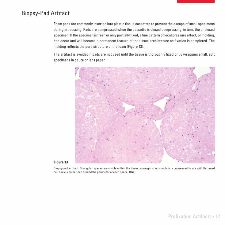
Foam pads are commonly inserted into plastic tissue cassettes to prevent the escape of small specimens during processing. Pads are compressed when the cassette is closed compressing, in turn, the enclosed specimen. If the specimen is fresh or only partially fi xed, a fi ne pattern of local pressure effect, or molding, can occur and will become a permanent feature of the tissue architecture as fi xation is completed. The molding refl ects the pore structure of the foam (Figure 13).
The artifact is avoided if pads are not used until the tissue is thoroughly fi xed or by wrapping small, soft specimens in gauze or lens paper.
Figure 13
Biopsy-pad artifact. Triangular spaces are visible within the tissue; a margin of eosinophilic, compressed tissue with fl attened cell nuclei can be seen around the perimeter of each space; H&E.

18 / Leica Microsystems – Scientia
Freezing Damage
It is common in many laboratories after frozen sections are cut to thaw the tissue block in fi xative and process to paraffi n for confi rmation of the diagnosis. These specimens may contain ice crystal damage as well as more subtle freeze-thaw changes.
For instance in frozen, thawed and fi xed tissue the nuclei may be surrounded by a clear space and appear slightly smaller with condensed, darker-staining chromatin (Figure 14). Also the general nuclear and cytoplasmic detail is not as well defi ned. These effects are not uniformly distributed across the section but tend to occur in irregular patches.
Figure 14
Section of lymph node which has been frozen, thawed, fi xed then processed to paraffi n; H&E.

Prefi xation Artifacts / 19
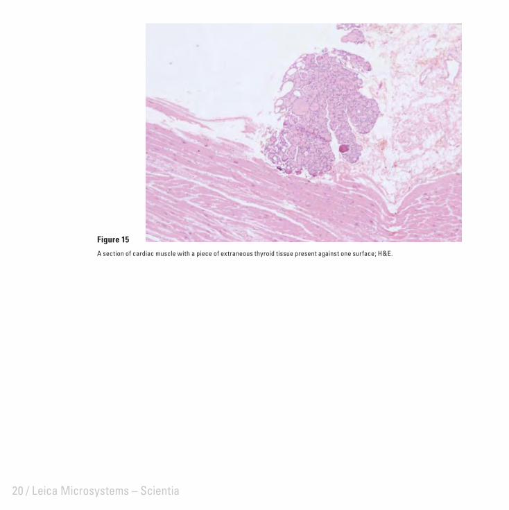
Specimen-to-Specimen Contamination
Most specimen-to-specimen contamination (Figure 15) probably occurs during dissection where tissue from a previous specimen is transferred via the instruments used (such as scalpel blades) or from fragments which remain on the dissecting board surface. Thorough rinsing of the board and instruments between specimens or covering the dissection board with separate paper sheets will avoid this problem. Reusable processing components (such as tissue cassette lids), if not thoroughly cleaned, can also carry fragments of previous specimens.
It is possible for tissue fragments to pass directly from one cassette to another during processing or from previously used reagents. This risk can be reduced through the judicious selection of cassettes and by ensuring that foam pads or other enclosures contain the specimen and that only uncontaminated reagents are used for processing.
Specimen transfer may occur infrequently during other stages of section preparation including:
during specimen embedding via contaminated forceps, moulds, hot plates and cassette covers• via section fl otation baths (these should always be skimmed between samples to remove any section • fragments from previous specimens which may remain) – this form of contaminant can often be detected from its position on the slide in relation to the actual sectionduring staining if cells are shed from a section or cytological smear and deposited on another slide•
The possibility for undetected contamination of a specimen with tissue of a similar type (for example endometrial tissue with endometrial fragments) should not be overlooked. The consequences of such contamination could, at worst, lead to an inaccurate diagnosis. It is clearly important therefore to remove the potential for specimen-to-specimen contamination as far as possible.
20 / Leica Microsystems – Scientia
Figure 15
A section of cardiac muscle with a piece of extraneous thyroid tissue present against one surface; H&E.
/ 21
Fixation ArtifactsThe process of fi xation can produce artifacts in tissues if the procedure is not carried out under optimal conditions, if fi xative does not have proper access to the tissues, or because of the nature and quality of the particular reagent used.

22 / Leica Microsystems – Scientia
Zonal Fixation
This artifact is most commonly seen in large specimens particularly those surrounded by a capsule as well as in tissue which degenerates rapidly (such as glandular tissue). It occurs when the fi xative penetrates slowly producing differing degrees of fi xation at different levels within the specimen (Figure 16). Common causes for this are insuffi cient time in fi xative, attempting to fi x a specimen which is too large, or by using a reagent with a poor penetration rate.
Figure 16
Zonal fi xation. A: A section of marrow aspirate where red blood cell lysis is evident in the left side of the fi eld whereas the cells in the adjacent area are intact; H&E. B: Liver trichrome stain showing uneven staining due to fi xation effects.
A B

Fixation Artifacts / 23
Streaming Artifact
Streaming artifact is caused through precipitation and displacement of glycogen by an advancing fi xation front. It is often seen in formalin fi xed liver (Figure 17) but may not be as obvious with preferred glycogen fi xatives (such as formal-alcohol or Bouin). It can be completely avoided by freeze-drying.
Figure 17
Streaming artifact in a formalin-fi xed section of liver; PAS.
24 / Leica Microsystems – Scientia
Formalin Pigment
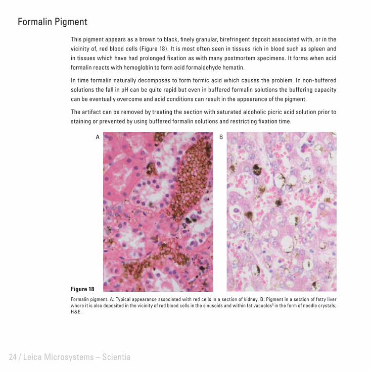
This pigment appears as a brown to black, fi nely granular, birefringent deposit associated with, or in the vicinity of, red blood cells (Figure 18). It is most often seen in tissues rich in blood such as spleen and in tissues which have had prolonged fi xation as with many postmortem specimens. It forms when acid formalin reacts with hemoglobin to form acid formaldehyde hematin.
In time formalin naturally decomposes to form formic acid which causes the problem. In non-buffered solutions the fall in pH can be quite rapid but even in buffered formalin solutions the buffering capacity can be eventually overcome and acid conditions can result in the appearance of the pigment.
The artifact can be removed by treating the section with saturated alcoholic picric acid solution prior to staining or prevented by using buffered formalin solutions and restricting fi xation time.
Figure 18
Formalin pigment. A: Typical appearance associated with red cells in a section of kidney. B: Pigment in a section of fatty liver where it is also deposited in the vicinity of red blood cells in the sinusoids and within fat vacuoles5 in the form of needle crystals; H&E.
A B

Fixation Artifacts / 25
Mercury Pigment
Fixation in mercuric chloride-containing fi xatives produces a brown to black granular deposit distributed randomly throughout the tissues (Figure 19). Mercury pigment can be removed by treating the section with Lugol’s iodine or alcoholic iodine solution and then bleaching the section with sodium thiosulphate. The use of mercuric chloride in fi xatives should be actively discouraged because of its highly toxic nature. Zinc salts used in fi xatives as a substitute for mercuric chloride do not produce artifact pigments.
Figure 19
Mercury pigment (B5 fi xative) in a section of kidney; H&E.

26 / Leica Microsystems – Scientia
/ 27
Tissue-Processing ArtifactsArtifacts that occur during processing to paraffi n wax may be the result of inadequate or incomplete fi xation or some processing fault. It is inevitable that some shrinkage and distortion will occur during processing.

28 / Leica Microsystems – Scientia
Vessel Shrinkage in Central Nervous System
Perivascular shrinkage in nerve tissue (Figure 20) can largely be avoided by perfusion fi xation and gentle, prolonged processing using chloroform as a clearing agent. Celloidin-paraffi n double embedding may also be helpful. A similar effect can frequently be seen around large neurons.
Figure 20
Paraffi n section of brain stem. Perivascular separation of dense nervous tissue at the junction of the adventitia and glial membrane is due to poor fi xation; H&E.

Tissue-Processing Artifacts / 29
Poor Processing
Extensive loss of architectural detail and clarity within loose connective tissue may refl ect inadequate fi xation, but can also be caused by faults in tissue processing (Figure 21). These include too short a processing cycle (especially wax infi ltration times), inappropriate choice of reagents, use of exhausted reagents, a mechanical fault with the processor, or an error in replacing solvents on the processing machine.
Figure 21
As a result of poor processing this breast specimen shows extensive tissue disruption within the loose connective tissue; H&E.

30 / Leica Microsystems – Scientia
Loss of Soluble Substances
Cholesterol is seen as tapering needle-like crystals in vessel walls in atheroma and various sites of old hemorrhage. The crystals dissolve during processing leaving spaces of characteristic shape (Figure 22). A more common example of the loss of soluble substances is seen when neutral lipid is dissolved from adipose cells leaving regular ovoid spaces surrounded by a rim of cytoplasm.
Figure 22
Cholesterol clefts in a section of oral cyst; H&E.

/ 31
Artifacts of Microtomy andSection Mounting
Various forms of mechanical damage produced during section cutting and fl otation, together with a range of contaminants from a variety of sources, are commonly encountered in sections.

32 / Leica Microsystems – Scientia
Knife Lines
Scores in sections are the result of a damaged knife edge (Figure 23). Knife lines may extend across the whole fi eld but more commonly appear as a single score running across the section in the direction of cutting. Severe scoring can usually be seen macroscopically.
Knife edges may be faulty initially (disposable blades may be defective as supplied or conventional steel knives may be inadequately sharpened), or are damaged through careless handling (for example by contact with forceps) or when sectioning hard material such as foci of calcifi cation within the block. In the last instance surface decalcifi cation before cutting is recommended.
Figure 23
Knife lines in a section of spleen; H&E.

Artifacts of Microtomy and Section Mounting / 33
Displacement of Components
Displacement of tissue components can occur during section cutting, mounting, or at some later stage and is commonly seen in sections of bone (Figure 24). It can also affect collagen, elastic, or reticular fi bers causing them to become re-aligned along the direction of cutting. Displacement can be caused by a dull knife, excessively rough sectioning, using an embedding medium which is too soft for the density of the tissue being cut, careless fl otation technique, incorrect blotting or poor adhesion of sections (leading to lifting during staining or coverslipping).
Figure 24
Displacement of cancellous bone in a trephine section stained for reticulin.

34 / Leica Microsystems – Scientia
Venetian Blind Effect
Fine parallel cracking in sections is usually caused by tiny vibrations in the knife edge as it passes through hard, brittle blocks (Figure 25). It most often occurs when disposable blades are not properly supported in the knife holder. Excessive hardness and brittleness in blocks caused by over-processing, over-heating during infi ltration and embedding, or over-chilling followed by excessively rough or rapid cutting may also produce this effect. Cutting thinner sections or softening the block before cutting will normally overcome micro-chatter.
Figure 25
Micro-chatter in a section of rodent liver stained for reticulin.

Artifacts of Microtomy and Section Mounting / 35
Coarse Chatter
Coarse chatter usually occurs when cutting dense tissue (particularly uterus and cervix) in large blocks or when movement of the specimen holder, knife or knife holder causes vibration in the section (Figure 26). The effect can also be seen in a poorly designed microtome albeit in perfect mechanical condition.
Coarse chatter can be avoided by using a properly maintained microtome of suitable design and by cutting appropriately processed blocks of a sensible size. Care must also be taken to clamp the specimen, knife and knife holder fi rmly.
Figure 26
Coarse chatter in a section of cervix; H&E.

36 / Leica Microsystems – Scientia
Holes from Roughing
This effect may occur when sectioning lymph node and other very cellular organs. Excessively rough trimming pulls tissue fragments from the block face and these appear as holes in subsequent thin sections (Figure 27). The effect can usually be seen when fl oating sections on the waterbath.
Figure 27
Roughing effect in a section of lymph node. The parallel alignment seen in this particular example is not always evident; H&E.

Artifacts of Microtomy and Section Mounting / 37
Tidemark due to Adhesive
The pale amorphous, hematoxylin-stained deposits in Figure 28 are caused by the pooling and subsequent evaporation of fl otation fl uid containing dichromate-gelatin adhesive. The pools are more likely to occur in irregular, poor quality sections where protein-based adhesives are used and sections are not drained of excess adhesive before drying. In this example the section was dried fl at on a hot-plate.
Figure 28
Adhesive pool artifact; H&E.

38 / Leica Microsystems – Scientia
Bubbles Under Section
Air bubbles trapped in a section after fl otation and mounting can collapse on drying leaving zones which crack and fail to adhere properly to the slide. These regions often display altered staining (Figure 29).
The bubbles may be caused by poor fl otation technique, where a section is dropped rather than pulled gently across the water surface. Alternatively, bubbles already present in the bath can be dislodged by the slide and rise up under the section. Freshly boiled water used in fl otation baths is less likely to produce bubbles.
Figure 29
Section of lymph node showing circular darkly stained areas with pale centers and surrounding radial cracks. These faults indicate collapsed bubble artifact; H&E.
Artifacts of Microtomy and Section Mounting / 39
Sneeze Artifact
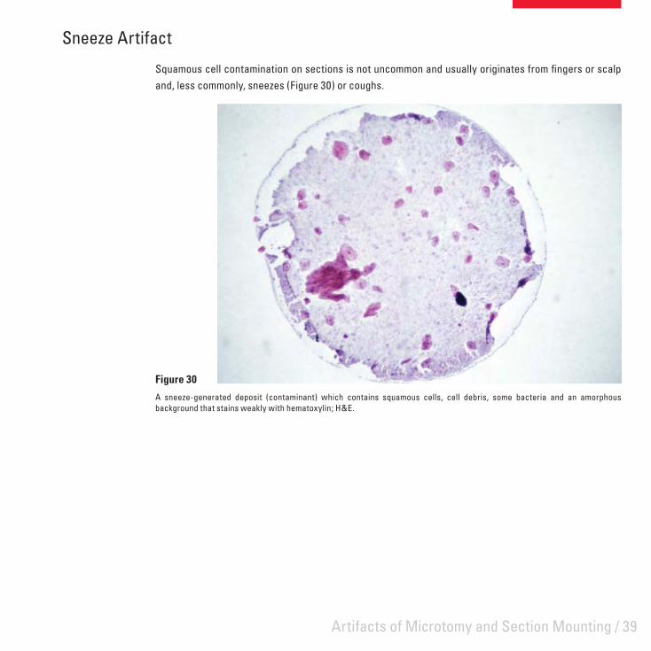
Squamous cell contamination on sections is not uncommon and usually originates from fi ngers or scalp and, less commonly, sneezes (Figure 30) or coughs.
Figure 30
A sneeze-generated deposit (contaminant) which contains squamous cells, cell debris, some bacteria and an amorphous background that stains weakly with hematoxylin; H&E.

40 / Leica Microsystems – Scientia
Contamination of Mounted Sections
Mounted, unstained sections left uncovered, can become contaminated with various materials including:
microorganisms, particularly airborne fungi (Figure 31)• airborne fi bers (Figure 32)• hair from the brush used to transfer sections from knife edge to fl otation bath (Figure 33)• cellulose fi bers from facial tissues used to skim fl otation baths or wipe slides and coverslips (Figure 34)• dirt (Figure 35).•
Figure 31
A semi-thin resin section of kidney which has become contaminated with fungal hyphae and conidia when left, unprotected, on a hotplate overnight to dry; PAS.

Artifacts of Microtomy and Section Mounting / 41
Figure 32
Fiber of unknown origin contaminating a section of skin. Despite investigation of a range of potential local sources the origin of these fi bers was never identifi ed; H&E.
Figure 33
Section of vagina showing a hair beneath the section; H&E.

42 / Leica Microsystems – Scientia
Figure 34
Cellulose fi ber contamination in a section of ureter; H&E.
Figure 35
Liver section showing dirt which was deposited on the section prior to staining, probably during drying. This highlights the importance of absolute cleanliness at all stages of section preparation.

Artifacts of Microtomy and Section Mounting / 43
Folds
Cartilage is one of several problem tissues likely to show folds after fl otation (Figure 36). The folds are diffi cult to avoid unless specialized techniques, such as double-embedding or resin embedding, are used. Folding is caused by cartilage shrinking less than other tissue types during processing followed by variable expansion on fl otation. These faults are readily identifi ed macroscopically. Careful microtomy and fl otation techniques minimize this problem.
Figure 36
Folds in an island of hyaline cartilage. Guinea pig trachea; H&E.

44 / Leica Microsystems – Scientia

/ 45
Staining ArtifactsArtifacts which arise during staining fall into two main groups: incomplete or patchy staining in otherwise satisfactorily stained preparations, and precipitates or contaminants derived from the staining solution(s). Patchy or incomplete staining is most commonly seen as areas devoid of all or some of the stain components.

46 / Leica Microsystems – Scientia
Residual Wax
Residual wax in a section will prevent the penetration of both aqueous and alcoholic dye solutions leaving areas totally devoid of stain (Figure 37). The fi nal clearing of the section before coverslipping removes all traces of the wax leaving no evidence as to the cause of the patchy staining. Traces of residual wax can also have a subtle effect on nuclear staining, producing small patches in sections where nuclei appear muddy and lack detail. Prolonged xylene treatment and re-staining will overcome this problem. These faults are readily identifi ed macroscopically.
Figure 37
A section of skin in which the superfi cial epidermis and keratin have failed to stain with either hematoxylin or eosin because of residual wax; H&E.

Staining Artifacts / 47
Incomplete Staining
Incomplete staining with one dye in a multi-step procedure may result from an inadequately fi lled staining dish (Figure 38). This is most commonly observed with automated staining machines.
Figure 38
A liver section stained on a linear stainer shows satisfactory hematoxylin staining throughout but an absence of eosin at one end of the section. This was due to an inadequate level of eosin in the container.

48 / Leica Microsystems – Scientia
Unstained Area in Section
Unstained areas in a section may occur when solvent is allowed to accumulate at the top of the slide during the dewaxing process, either because the dewaxing bath is fi lled to a level above that of the alcohol baths, or solvent is trapped between the slide holder and slide. In both situations beads of water-immiscible solvent collect above the section and may streak down the slide at any stage to prevent staining by aqueous dyes.
A variant of this artifact is shown in Figure 39. The section of liver, stained by Shikata’s orcein method for hepatitis B antigen, shows a deeply stained focus of cells. This method requires pretreatment of the section with potassium permanganate and oxalic acid to reduce background staining. Exposure to these reagents appears to have been prevented, possibly by traces of solvent which may have remained in the section. The orcein stain, prepared in alcohol, has had full access to the tissue. This phenomenon will show the reverse effect when the contaminants prevent the access of aqueous dyes to tissues resulting in pale or unstained areas in the section.
The remedy to these artifacts is essentially good technique, frequent replenishment of dewaxing solvents, and maintenance of correct levels in the staining baths.
Figure 39
Section of liver showing a deeply stained focus of cells where suppression of the background staining has failed (see text for details); Shikata’s orcein.

Staining Artifacts / 49
Stain Deposit
This type of artifact may arise from undissolved stain, stain precipitate or any solid component in an unfi ltered staining solution (Figure 40). Precipitation can occur when volatile solvents are used and in methods which require heat or long staining times. The problem is increased when slides are stained on open racks. The use of sealed staining jars which hold slides vertically will eliminate most artifacts due to precipitates.
Figure 40
A precipitate of alcian blue deposited on the tissue section and to a lesser extent on the slide.

50 / Leica Microsystems – Scientia
Contaminated Staining Solution
Contamination of staining solutions by microorganisms which are subsequently deposited on the section (Figure 41) is readily identifi ed and prevented by regular replacement of solutions prone to microbial growth, or by adding a preservative such as thymol or merthiolate. Filtration of the staining solution may overcome an immediate problem.
Figure 41
The effect of staining with a solution contaminated by microorganisms.

Staining Artifacts / 51
Mucus Contamination
The standard procedure for the demonstration of glycogen in histological sections utilizes the PAS reaction preceded by diastase digestion as a negative control. Human saliva is a convenient, reliable, and cost-free source of this enzyme. However, failure to adequately wash sections after incubation with saliva may lead to strong PAS staining in residual mucus (Figure 42). The potential for mucus contamination can be minimized by diluting the saliva with water or saline; the use of commercial lyophilized diastase preparations eliminates the problem.
Figure 42
A bone marrow section treated with saliva prior to PAS staining. Mucus strands, which have not washed off prior to PAS staining cover the section.

52 / Leica Microsystems – Scientia

/ 53
Section Preservation ArtifactsDegeneration artifacts which develop in sections during storage may not be evident for months or even years. This can cause major problems when reviews of archival material are required.

54 / Leica Microsystems – Scientia
Drying Artifact
The common problem of large air bubbles in the mountant is easily recognized; a less obvious variant is shown in Figure 43. The appearance of dark nuclei, lacking visible detail occurs when excessive time is taken between removing the slide from xylene and applying the coverslip. The section starts to dry and minute bubbles become trapped over the nuclei when the coverslip is applied. Remounting sections will usually overcome the problem.
Figure 43
Drying artifact in a section of liver; H&E.

Section Preservation Artifacts / 55
Water in Section
Since water is immiscible with clearing agents, sections which have not been adequately dehydrated will be opaque due to the presence of water (Figure 44). Sometimes small water droplets may also be seen microscopically. The presence of water masks microscopic detail and causes leaching of stains. If water is detected in a section the coverslip should be removed, the section washed in clearant then returned to alcohol. When the residual water has been removed the section can be cleared and remounted.
Figure 44
Dehydration fault in a section of liver; H&E.

56 / Leica Microsystems – Scientia
Figure 45
Polystyrene mountant breakdown. A: Crazing (cracking). B: Crystallization (presence of spherocrystals)
Mountant Breakdown
Incorrectly prepared polystyrene-based mountants are prone to degenerate over time (Figure 45). Should this occur remove the coverslip and defective mountant and remount with a proven product.
A B
Section Preservation Artifacts / 57
Bleaching of Stain
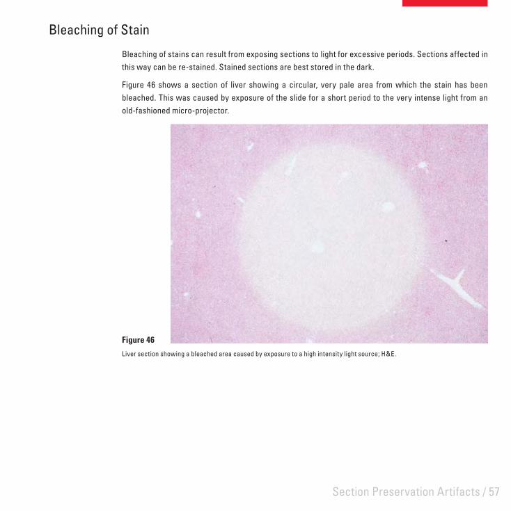
Bleaching of stains can result from exposing sections to light for excessive periods. Sections affected in this way can be re-stained. Stained sections are best stored in the dark.
Figure 46 shows a section of liver showing a circular, very pale area from which the stain has been bleached. This was caused by exposure of the slide for a short period to the very intense light from an old-fashioned micro-projector.
Figure 46
Liver section showing a bleached area caused by exposure to a high intensity light source; H&E.

58 / Leica Microsystems – Scientia

/ 59
Artifacts in Frozen SectionsAlthough many of the artifacts encountered in paraffi n sections may also occur in frozen sections, there are some that are particular to frozen sections.

60 / Leica Microsystems – Scientia
Ice Crystal Artifact
Ice crystal artifact is one of the more common and potentially serious artifacts in frozen sections as it often makes diagnosis diffi cult or impossible (and once formed cannot be overcome). The effect appears as intercellular clefts in highly cellular tissues and as intracellular clefts and vacuoles in skeletal muscle (Figure 47). Ice crystal artifact results from the slow freezing of tissue, inappropriate quenching techniques or the selection of tissue samples too large to permit rapid freezing. Consequently damage is most prominent in the central region of the specimen. While this artifact is usually associated with unexpected urgent frozen sections where attention to optimal freezing technique is often secondary to speed, severe ice crystal artifact also occurs in large specimens (particularly amputated limbs) frozen for preservation or to facilitate sampling – a practice not to be recommended.
Figure 47
Ice crystal artifact in a section of skeletal muscle; H&E.

Artifacts in Frozen Sections / 61
Frozen Section Chatter
Frozen tissues are prone to sectioning artifacts similar to those which affect paraffi n blocks. Chatter is one example – this occurs because the specimen is too cold and hard (Figure 48), the specimen or knife is poorly supported or adjusted, or the section thickness is too great.
Each tissue type has an optimal temperature for the preparation of frozen sections and, in the absence of other causes, chatter indicates the specimen is below its optimal sectioning temperature. Holding a gloved fi nger against the frozen tissue face will usually warm the specimen suffi ciently to allow one or two sections to be cut free from chatter.
Disposable microtome blades are less robust than conventional knives and their use has resulted in frozen section chatter becoming a more common problem. The optimal temperature of the tissue is critical with disposable blades and their low rigidity makes them more suited to small tissue samples and frozen sections of 5 μm in thickness or less.
Figure 48
Frozen section chatter. The temperature at which the specimen was cut was too low for satisfactory sections to be prepared.

62 / Leica Microsystems – Scientia
Figure 49
Cryostat sections of oral mucosa; H&E. A: Was immediately wet-fi xed in Carnoy’s fl uid. B: Was allowed to dry prior to fi xation.
Fuzzy Staining
Fuzzy or indistinct staining may be observed when frozen sections of fresh tissue are allowed to dry before fi xation. Figure 49A shows a cryostat sections of oral mucosa which was picked up on a slide and immediately wet-fi xed using Carnoy’s fl uid then stained H&E. It shows good nuclear and cytoplasmic detail. Another section from the same specimen was prepared in the same way except that it was allowed to dry before fi xation (Figure 49B). It shows poor nuclear detail, poorly defi ned cytoplasm and an overall loss of clarity. At higher magnifi cation nuclear and cytoplasmic vacuolation is evident.
A B
Artifacts in Frozen Sections / 63
Miscellaneous Artifacts
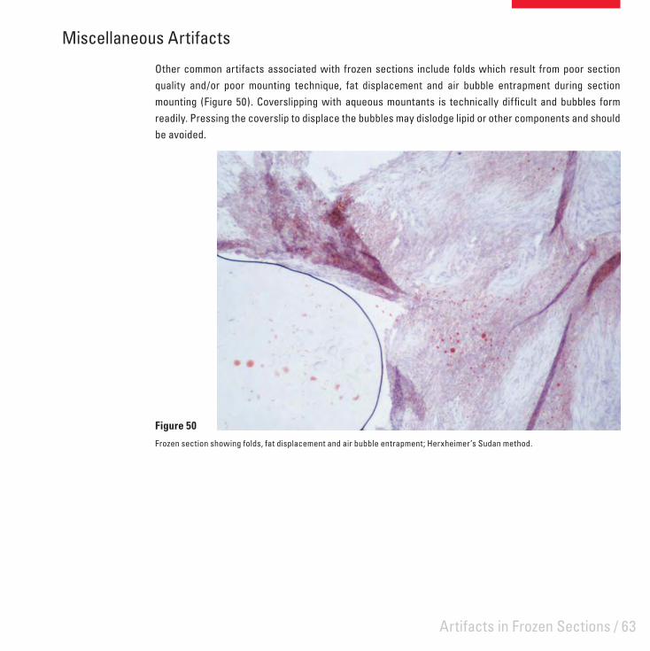
Other common artifacts associated with frozen sections include folds which result from poor section quality and/or poor mounting technique, fat displacement and air bubble entrapment during section mounting (Figure 50). Coverslipping with aqueous mountants is technically diffi cult and bubbles form readily. Pressing the coverslip to displace the bubbles may dislodge lipid or other components and should be avoided.
Figure 50
Frozen section showing folds, fat displacement and air bubble entrapment; Herxheimer’s Sudan method.
64 / Leica Microsystems – Scientia

/ 65
Artifacts in Bone and Calcified TissuesArtifacts in calcifi ed tissues may occur as a result of the sampling or collection techniques, from tissue processing including decalcifi cation, or because of factors related to microtomy.
66 / Leica Microsystems – Scientia
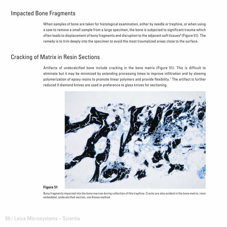
Impacted Bone Fragments
When samples of bone are taken for histological examination, either by needle or trephine, or when using a saw to remove a small sample from a large specimen, the bone is subjected to signifi cant trauma which often leads to displacement of bony fragments and disruption to the adjacent soft tissues6 (Figure 51). The remedy is to trim deeply into the specimen to avoid the most traumatized areas close to the surface.
Cracking of Matrix in Resin Sections
Artifacts of undecalcifi ed bone include cracking in the bone matrix (Figure 51). This is diffi cult to eliminate but it may be minimized by extending processing times to improve infi ltration and by slowing polymerization of epoxy resins to promote linear polymers and provide fl exibility.7 The artifact is further reduced if diamond knives are used in preference to glass knives for sectioning.
Figure 51
Bony fragments impacted into the bone marrow during collection of this trephine. Cracks are also evident in the bone matrix; resin embedded, undecalcifi ed section, von Kossa method.
Artifacts in Bone and Calcifi ed Tissues / 67
Bone Dust Artifact
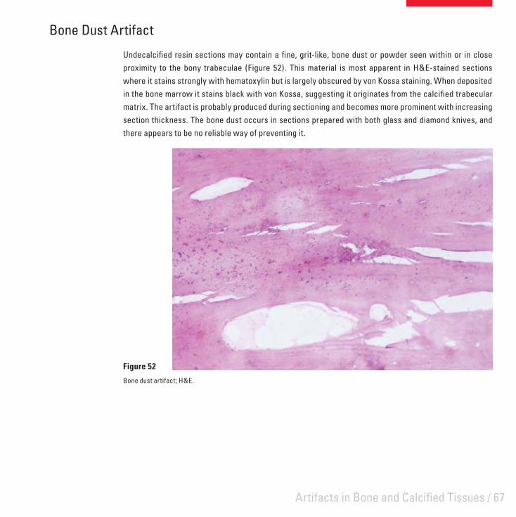
Undecalcifi ed resin sections may contain a fi ne, grit-like, bone dust or powder seen within or in close proximity to the bony trabeculae (Figure 52). This material is most apparent in H&E-stained sections where it stains strongly with hematoxylin but is largely obscured by von Kossa staining. When deposited in the bone marrow it stains black with von Kossa, suggesting it originates from the calcifi ed trabecular matrix. The artifact is probably produced during sectioning and becomes more prominent with increasing section thickness. The bone dust occurs in sections prepared with both glass and diamond knives, and there appears to be no reliable way of preventing it.
Figure 52
Bone dust artifact; H&E.
68 / Leica Microsystems – Scientia
Effects of Over-Decalcifi cation on Tissues
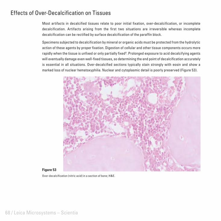
Most artifacts in decalcifi ed tissues relate to poor initial fi xation, over-decalcifi cation, or incomplete decalcifi cation. Artifacts arising from the fi rst two situations are irreversible whereas incomplete decalcifi cation can be rectifi ed by surface decalcifi cation of the paraffi n block.
Specimens subjected to decalcifi cation by mineral or organic acids must be protected from the hydrolytic action of these agents by proper fi xation. Digestion of cellular and other tissue components occurs more rapidly when the tissue is unfi xed or only partially fi xed8. Prolonged exposure to acid decalcifying agents will eventually damage even well-fi xed tissues, so determining the end point of decalcifi cation accurately is essential in all situations. Over-decalcifi ed sections typically stain strongly with eosin and show a marked loss of nuclear hematoxyphilia. Nuclear and cytoplasmic detail is poorly preserved (Figure 53).
Figure 53
Over-decalcifi cation (nitric acid) in a section of bone; H&E.

Artifacts in Bone and Calcifi ed Tissues / 69
Effects of Incomplete Decalcifi cation
Incomplete decalcifi cation of a specimen is clearly apparent when trimming a paraffi n block. As discussed previously, this problem is readily corrected, but there are associated problems such as damage to the microtome knife and to the soft tissues surrounding the calcifi ed areas. If sections can be obtained, the bony trabeculae stain strongly with hematoxylin (indicating residual calcium) and the adjacent soft tissue is severely disrupted (Figure 54).
Figure 54
Incomplete decalcifi cation in a section of cancellous bone; H&E.
70 / Leica Microsystems – Scientia
Limitations of Paraffi n Wax Embedding for Dense Bone
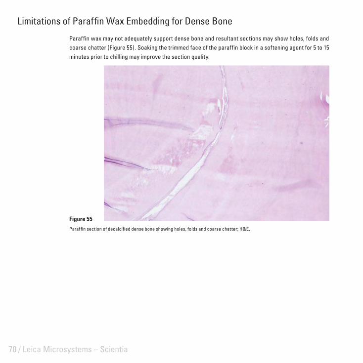
Paraffi n wax may not adequately support dense bone and resultant sections may show holes, folds and coarse chatter (Figure 55). Soaking the trimmed face of the paraffi n block in a softening agent for 5 to 15 minutes prior to chilling may improve the section quality.
Figure 55
Paraffi n section of decalcifi ed dense bone showing holes, folds and coarse chatter; H&E.

/ 71
Artifacts in Resin SectionsAlthough polymerizing resins are rarely used as embedding agents in routine histopathology, they are valuable for high resolution light microscopy and calcifi ed tissue research. Artifacts in resin sections can be quite subtle and diffi cult to overcome.

72 / Leica Microsystems – Scientia
Polymerization Artifacts in Epoxy Resin Sections
When used for small tissue samples, epoxy resins polymerize satisfactorily at 60°C in 16 hours (overnight). Large specimens are often not adequately polymerized in this time and may require up to 3 days. Occasionally a specimen may appear to section satisfactorily but on staining is found to show a “chatter-like” artifact which is limited to the central zone of the specimen with the tissue at the periphery well presented (Figure 56). This artifact can be signifi cantly reduced or abolished by returning the block to the 60°C oven for 24 hours. Failure to thoroughly mix the components of the epoxy resin and omitting the accelerator from the infi ltrating solutions will retard polymerization and can cause this problem.
Figure 56
Polymerization artifact in a 2 μm epoxy resin section of lymph node; H&E.
Artifacts in Resin Sections / 73
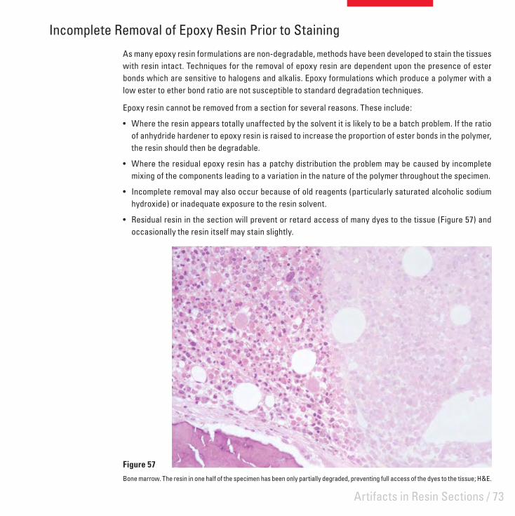
Incomplete Removal of Epoxy Resin Prior to Staining
As many epoxy resin formulations are non-degradable, methods have been developed to stain the tissues with resin intact. Techniques for the removal of epoxy resin are dependent upon the presence of ester bonds which are sensitive to halogens and alkalis. Epoxy formulations which produce a polymer with a low ester to ether bond ratio are not susceptible to standard degradation techniques.
Epoxy resin cannot be removed from a section for several reasons. These include:
Where the resin appears totally unaffected by the solvent it is likely to be a batch problem. If the ratio • of anhydride hardener to epoxy resin is raised to increase the proportion of ester bonds in the polymer, the resin should then be degradable.
Where the residual epoxy resin has a patchy distribution the problem may be caused by incomplete • mixing of the components leading to a variation in the nature of the polymer throughout the specimen.
Incomplete removal may also occur because of old reagents (particularly saturated alcoholic sodium • hydroxide) or inadequate exposure to the resin solvent.
Residual resin in the section will prevent or retard access of many dyes to the tissue (Figure 57) and • occasionally the resin itself may stain slightly.
Figure 57
Bone marrow. The resin in one half of the specimen has been only partially degraded, preventing full access of the dyes to the tissue; H&E.

74 / Leica Microsystems – Scientia
Effects of a Dull Knife on Epoxy Resin Sections
Epoxy sections can be cut with a glass or diamond knife. The quality of the cutting edge is critical for the production of sections suitable for high resolution microscopy. Macroscopically, sections prepared with a blunt or dull knife have a ground glass or opaque appearance, whereas those prepared using sharp knives appear glossy and transparent. Microscopically, the sections from a dull knife lack the sharp and crisp image associated with resin sections (Figure 58). While this is often a subtle artifact it is seen most frequently with bone specimens where the glass knife edge deteriorates rapidly from the sectioning of mineralized trabecular bone. Glass knives should be used as soon as possible after preparation and not stored for prolonged periods.
Figure 58
2 μm epoxy resin sections of bone marrow. A: Nuclear and cytoplasmic detail is poor because the knife has been dulled by cutting several sections prior to this one. B: Section cut from the same specimen with a fresh knife shows much better resolution.
A B
Artifacts in Resin Sections / 75
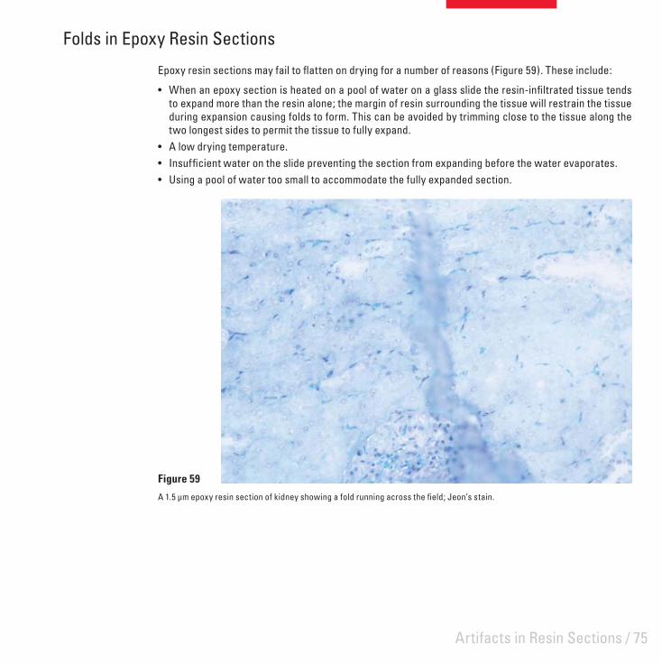
Folds in Epoxy Resin Sections
Epoxy resin sections may fail to fl atten on drying for a number of reasons (Figure 59). These include:
When an epoxy section is heated on a pool of water on a glass slide the resin-infi ltrated tissue tends • to expand more than the resin alone; the margin of resin surrounding the tissue will restrain the tissue during expansion causing folds to form. This can be avoided by trimming close to the tissue along the two longest sides to permit the tissue to fully expand.A low drying temperature.• Insuffi cient water on the slide preventing the section from expanding before the water evaporates.• Using a pool of water too small to accommodate the fully expanded section.•
Figure 59
A 1.5 μm epoxy resin section of kidney showing a fold running across the fi eld; Jeon’s stain.

76 / Leica Microsystems – Scientia
Background Staining in Acrylic Sections
Acrylic polymers are effectively insoluble and staining methods are performed with the resin intact. Contamination of the acrylic resin monomer with methacrylic acid from the initial synthesis of the resin or the breakdown of the monomer during storage will result in background staining with basic dyes (Figure 60). This artifact is easily monitored and overcome. When a signifi cant level of methacrylic acid is present the pH of the monomer (usually 7.0-7.4) falls below pH 7.0. The methacrylic acid is removed by passing the monomer through an ion exchange resin.
Figure 60
Section of mucosa embedded in LR White showing background staining; Toluidine blue.

/ 77
Histochemistry, Immunohistochemistry and Hybridization Histochemistry
Many artifacts encountered in routine histopathological techniques may also be seen in the more specialized preparations of histochemistry, immunohistochemistry and hybridization histochemistry. In addition there are some artifacts that are unique to these areas.

78 / Leica Microsystems – Scientia
Effect of Crush Artifact on Immunostaining
Tissues subjected to crush artifact may also show displacement of cellular antigens (Figure 61). (See also Crush Artifact).
Figure 61
A high grade B cell lymphoma stained for the lymphocyte marker L26. The specimen was crushed with forceps prior to formalin fi xation and paraffi n embedding and shows diffuse staining of both cytoplasm and background.

Histochemistry, Immunohistochemistry and Hybridization Histochemistry / 79
Non-specifi c Staining in Immunohistochemistry
Endogenous peroxidase and alkaline phosphatase are well recognized causes of non-specifi c staining in immunohistochemistry and the methods for blocking these enzymes are extensively documented. Endogenous peroxidase is localized in erythrocytes and to a lesser extent to granulocytes in both formalin fi xed and fresh tissues. Figure 62 shows residual peroxidase staining in laked red cells in a liver section stained for hepatitis B core antigen. Formalin pigment can be seen associated with these red cells. Endogenous alkaline phosphatase activity is not preserved in formalin fi xed paraffi n sections and is a problem only in frozen sections and smears.
Background staining of collagen is another common artifact which may be eliminated or reduced by predigestion with proteolytic enzymes and hyaluronidase, and by blocking with normal serum from the animal species used for linking or labeling. This artifact can be attributed to the physical trapping of the primary antibody in collagen and to electrovalent bonding of the antibody to collagen.
Figure 62
Residual endogenous peroxidase staining in laked red cells in a liver section stained for hepatitis B core antigen. Formalin pigment can also be seen associated with these red cells.

80 / Leica Microsystems – Scientia
Pigments
Localization of antigens in tissues by light microscopy is dependent upon the production of a colored fi nal reaction product at the site of the antigen. The chromogen diaminobenzidine, used to localize the marker enzyme horseradish peroxidase, gives a brown to black fi nal reaction product which contrasts poorly with many artifact and endogenous pigments commonly found in tissues. Some examples include carbon, formalin, tattoo, lipogenic, melanin, hemosiderin, and pseudomelanosis coli pigments. Careful examination of negative control sections before examination of the test material is essential to avoid misinterpreting such pigments as positive staining (Figure 63). In many instances pigments can be removed before staining, or alternatively chromogenic substrates which yield red or blue fi nal reaction products can be used.
Figure 63
Sections from the same case of melanoma. A: Stained for S100 with DAB as the chromogen. Here it is diffi cult to differentiate between the brown melanin pigment and the reaction product. B: Negative control slide showing the natural color of melanin only.
A B

Histochemistry, Immunohistochemistry and Hybridization Histochemistry / 81
Eosinophil Artifact in Hybridization Histochemistry
Non-specifi c labeling of eosinophils can occur when DNA probes incorporating radiolabels are used on cell smears of peripheral blood or on tissue sections (Figure 64). It is reported that using a stain for eosinophils (carbol chromotrope) blocks this non-specifi c binding but does not inhibit hybridization to specifi c nucleotide sequences.9
Figure 64
A frozen section of sheep adrenal hybridized with a 30mer oligonucleotide probe for side-chain cleavage enzyme, 32P labeled. Non-specifi c labeling of eosinophils is evident in the medulla.

82 / Leica Microsystems – Scientia
Crystallization Artifact
This artifact has been observed frequently in student preparations where a tetrazolium salt has been used in a standard method for the enzyme succinate dehydrogenase. This method is performed on fresh, unfi xed cryostat sections which are fi nally fi xed in formalin after incubation in a substrate solution which contains a substituted tetrazolium salt (Nitro BT) and the natural substrate sodium succinate. The reaction product is an intensely colored formazan which is preserved by mounting in an aqueous mountant.
Figure 65, a section of rat kidney, shows the colored needle-crystals that appear in the section when it is not thoroughly washed in water following fi xation and prior to mounting. After several weeks the stained tissue underlying the crystals also becomes bleached. The crystals are probably produced from residual tetrazolium salt which has not been washed from the section and is concentrated in the aqueous mountant as it dries out. Thorough washing prior to mounting prevents the occurrence of this artifact.
Figure 65
Cryostat section of rat kidney showing crystalline deposit at reaction site; SDH method.

/ 83
Miscellaneous ArtifactsThis category includes artifacts where the cause is not fully understood or where the cause may be multi-factorial.

84 / Leica Microsystems – Scientia
Nuclear Meltdown
Nuclear meltdown is one of a number of descriptive names given to a group of artifacts which are characterized by poorly demonstrated cell nuclei. The causes of these artifacts are poorly understood and have been the subject of ongoing debate for many years.10,11 Because there are a number of possible contributing factors the precise cause of any particular instance may be impossible to pin down, however poor fi xation does not appear to cause this artifact.
Nuclear meltdown may present the following characteristics.
The presence of poorly defi ned nuclear membranes.• The presence of chromatin that lacks defi nition (it may appear amorphous, like cut glass, or blurry, and • can range from very pale to quite dense).The presence of a blue hue or blue haze (more of a royal blue color than the purple/blue of properly • stained nuclei in the same section).A patchy distribution which may affect only small parts of the whole section (for example, in a section • of intestine or skin it may be present in only some areas of the epithelium with underlying tissues unaffected).It may affect a variable number of specimens in a batch ranging from one or two to many.• It may affect particular types of specimens only. Common specimens affected are: gastro-intestinal tract • (particularly endoscopies), prostate, lymphoid tissue and bone marrow, spleen, skin and endometrium. Epithelial and lymphoid tissue appear to be the most susceptible.It may occur periodically, troubling a laboratory for a time and then disappearing only to reappear • weeks or months later.
The following are some of the causes of nuclear meltdown that have been suggested.
Allowing a specimen to dry out before fi xation• 12 ( eg. by placing fresh, unfi xed tissue on a dry absorbent surface). This can certainly be a problem with tiny endoscopic specimens.Using xylene that is contaminated with water during the clearing step in processing. In this situation it • has been suggested that the problem can be overcome by reprocessing the specimen.13
Using wax which is contaminated with formalin or both formalin and ethanol during processing.• 13 This problem can be caused by a faulty tissue processor (particularly a fl uid-transfer machine) and appears to permanently damage the tissue.Failing to completely replace solvent with wax during processing (retained solvent). This may be caused • by using a protocol that is too short for the dimensions and nature of the specimen, using expired or contaminated reagents for processing or by a tissue processor fault. In this case reprocessing the specimen may overcome the problem.Over-heating the section when drying prior to staining (a faulty slide dryer producing hot-spots in the • section).

Miscellaneous Artifacts / 85
Ineffective dewaxing of sections prior to staining leaving traces of wax in the section that may impair • nuclear staining. The nuclei will fail to stain properly with hematoxylin and may take up eosin producing so-called “pink disease”.14,15 Extended dewaxing time and fresh solvent may overcome this cause of the problem.
Figure 66 shows the typical features of nuclear meltdown with the chromatin being very poorly defi ned with a hazy blue hue. A portion of the mucosa in the intestine (66A) was affected in this way with some adjacent areas being normally preserved. Nuclei in a small area of the epidermis and dermis in the skin section (Figure 66B) were similarly affected. In both cases the specimens were well-fi xed and processed on a four-hour cycle. Here the problem was most likely caused by retained solvent in the tissue.
Figure 66
Examples of typical nuclear meltdown. A: Intestinal mucosa; H&E. B: Skin, H&E.
A B

86 / Leica Microsystems – Scientia
Myocardial Fragmentation
Transverse fragmentation of myocardial fi bers (Figure 67) has long been recognized as an artifact of cardiac muscle sections although it is not always evident and is not seen in endomyocardial biopsies. The cause of the artifact remains obscure.
Figure 67
Myocardial fragmentation; H&E.
Miscellaneous Artifacts / 87
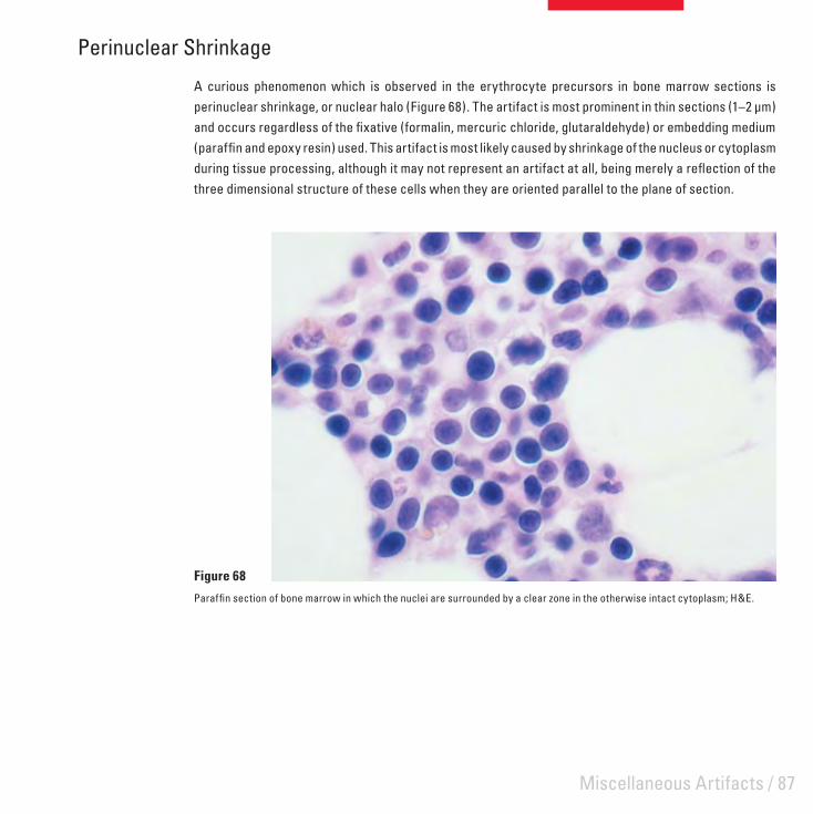
Perinuclear Shrinkage
A curious phenomenon which is observed in the erythrocyte precursors in bone marrow sections is perinuclear shrinkage, or nuclear halo (Figure 68). The artifact is most prominent in thin sections (1–2 μm) and occurs regardless of the fi xative (formalin, mercuric chloride, glutaraldehyde) or embedding medium (paraffi n and epoxy resin) used. This artifact is most likely caused by shrinkage of the nucleus or cytoplasm during tissue processing, although it may not represent an artifact at all, being merely a refl ection of the three dimensional structure of these cells when they are oriented parallel to the plane of section.
Figure 68
Paraffi n section of bone marrow in which the nuclei are surrounded by a clear zone in the otherwise intact cytoplasm; H&E.

88 / Leica Microsystems – Scientia

/ 89
Artifacts in Cytological PreparationsVarious types of artifacts can be encountered in cytological preparations. They are usually caused by inappropriate handling before fi xation, the fi xation process itself, or are due to contaminants present in the material taken for examination or introduced at some later stage.

90 / Leica Microsystems – Scientia
Cardboard Imprint
Cardboard imprint (also known as packing artifact) is the result of contact between slide holders and smears which are wet with fi xative (Figure 69).
Figure 69
A Papanicolaou-stained smear showing a pattern produced by contact with the cellulose fi bers in the lid of the cardboard slide-holder into which the smear was placed while still wet with fi xative.

Artifacts in Cytological Preparations / 91
Drying Prior to Fixation
Smears to be stained by the Papanicolaou method should be prepared on the slide then immediately wet-fi xed, without drying. Allowing a smear to dry before fi xation results in a lack of cellular detail and poor staining (Figure 70).
Figure 70
An ascites fl uid. The smear was allowed to completely dry before fi xation and shows marked cellular enlargement and eosinophilia in addition to a lack of nuclear and cytoplasmic defi nition; Papanicolaou.

92 / Leica Microsystems – Scientia
UV Artifact
The methanol fi xed, May-Grünwald Giemsa stained smear shown in Figure 71 shows an artifact which was accidentally induced and required careful investigation in order to establish a cause. Cells in the smear show loss of crisp nuclei and an uneven vacuolated appearance. The smear was one of a group which were prepared then left overnight in a biohazard cabinet with the ultraviolet lights on before fi xation and staining the next morning. The effects observed were apparently due to the irradiation with ultraviolet light.
Figure 71
Methanol fi xed smear showing the effects of radiation with ultraviolet light; May-Grünwald Giemsa.

Artifacts in Cytological Preparations / 93
Propellant Contamination
This artifact occurs when pressure-packs (of hair spray) used for fi xation are almost empty and the spray consists mostly of propellant (hydrocarbons) and very little alcohol (which acts as the fi xative). It appears to be a defect of fi xation. Hair spray is no longer recommended for fi xation because of this risk.16 Cells appear dark with the normal range of colors seen in a Papanicolaou stain and are masked by an overall grey-blue coloration and some fi ne granularity (Figure 72 A). The problem can be largely overcome by soaking smears overnight in 2% aqueous hydrochloric acid then re-staining (Figure 72 B).
Figure 72
A: Smear showing pressure pack artifact. B: Smear after acid treatment and re-staining; Papanicolaou.
A B
94 / Leica Microsystems – Scientia
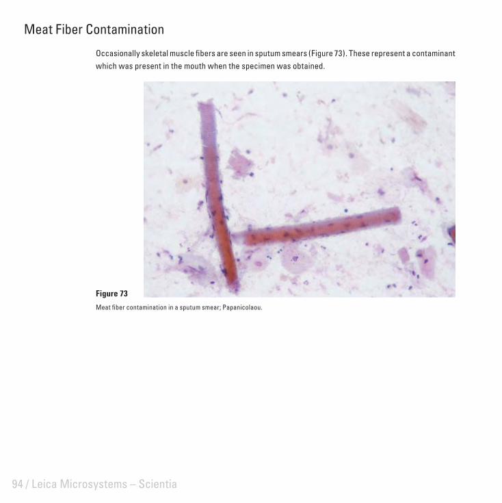
Meat Fiber Contamination
Occasionally skeletal muscle fi bers are seen in sputum smears (Figure 73). These represent a contaminant which was present in the mouth when the specimen was obtained.
Figure 73
Meat fi ber contamination in a sputum smear; Papanicolaou.

Artifacts in Cytological Preparations / 95
Insect Contaminant
Figure 74 illustrates two different cervical smears collected on the same occasion and stained by the Papanicolaou method. The smears contain contaminant material which may have arisen from an insect of some type or other unidentifi ed source. These contaminants could have been present within the vagina originally or were introduced from an external source as the smear was taken or spread on the slide.
Figure 74
Cervical smears showing insect contaminant; Papanicolaou.
A B
96 / Leica Microsystems – Scientia
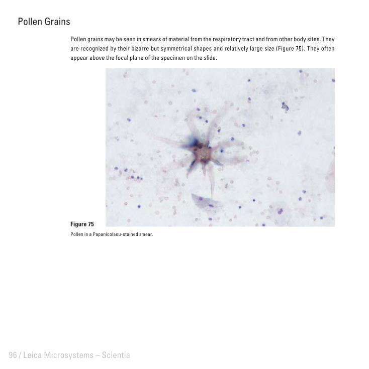
Pollen Grains
Pollen grains may be seen in smears of material from the respiratory tract and from other body sites. They are recognized by their bizarre but symmetrical shapes and relatively large size (Figure 75). They often appear above the focal plane of the specimen on the slide.
Figure 75
Pollen in a Papanicolaou-stained smear.

Artifacts in Cytological Preparations / 97
Alternaria Contamination
Alternaria, an airborne fungus, may settle on smears at any stage of preparation. The organism displays a branching mycelium and ‘snowshoe’-shaped macro-conidia although the latter are more commonly seen alone (Figure 76). Storage of smears in covered containers prior to staining prevents this form of contamination.
Figure 76
Alternaria in a Papanicolaou-stained cervical smear.

98 / Leica Microsystems – Scientia
Lubricant Contamination
An occasional contaminant seen in cervical smears is derived from lubricant jelly which has been introduced before taking the smear (Figure 77). The presence of the lubricant interferes with the visualization of the cells and stains an intense blue-black with the Papanicolaou stain.
Figure 77
A and B show the typical appearance of lubricant deposits in smears. Note the cross-like appearance inside the deposits present in A.
A B
Artifacts in Cytological Preparations / 99
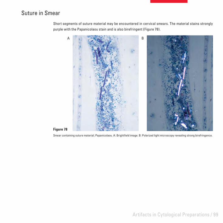
Suture in Smear
Short segments of suture material may be encountered in cervical smears. The material stains strongly purple with the Papanicolaou stain and is also birefringent (Figure 78).
Figure 78
Smear containing suture material; Papanicolaou. A: Brightfi eld image. B: Polarized light microscopy revealing strong birefringence.
A B

100 / Leica Microsystems – Scientia

/ 101
List of Common Artifacts Common Name Alternative Description Page
Prefi xation ArtifactsHeat damage Laser knife damage
Cauterization damageThermal dehydration
5
Presence of sutures Silk suturesStitch granuloma
6
Cellulose contamination Cellulose fi ber 7
Gelfoam artifact Gelfi lm artifactSurgical sponge contaminantSurgical packing
8
Starch contamination Starch granulomaGlove powder contamination
9
Catheter damage Surgery-induced artifactEpithelial compression
10
Crush artifact Compression artifactSurgical trauma
11
Necrosis due to Monsel’s solution Monsel’s artifact 12
Tattoo pigment Tattoo artifact 13
Postmortem change AutolysisPutrefactionMicroorganisms introduced postmortem
14
Desquamation Epithelial sheddingAutolytic change
15
Specimen marking dyes Silver nitrate contaminationIndia ink contamination
16
Biopsy-pad artifact Foam-pad damageEnclosure damagePressure effects
17
Freezing damage Freeze-thaw-fi x artifactFreezing artifact
18

102 / Leica Microsystems – Scientia
Common Name Alternative Description Page
Specimen-to-specimen contamination Translocation of tissueTissue transferContamination with tissue debris
19
Fixation ArtifactsZonal fi xation Penetration artifact 22
Streaming artifact Glycogen streamingPolarization displacement
23
Formalin pigment Acid formaldehyde hematinFormalin deposit
24
Mercury pigment Mercuric chloride depositSublimate deposit
25
Tissue-Processing ArtifactsVessel shrinkage in central nervous system Perivascular shrinkage 28
Poor processing Under-processingInfi ltration faultClearing fault
29
Loss of soluble substances Cholesterol clefts 30
Artifacts of Microtomy and Section MountingKnife lines Scoring 32
Displacement of components Translocation Realignment of fi bers
33
Venetian blind effect Micro-chatter 34
Coarse chatter Mechanical vibration 35
Holes from roughing Moth-eaten effect 36
Tidemark due to adhesive Adhesive pools 37
Bubbles under section Collapsed-bubble artifact 38

/ 103
Common Name Alternative Description Page
Contamination of mounted sections Sneeze artifactContamination during mountingContamination with squamesAirborne contaminationFungal contaminationCellulose contaminationFiber from facial tissueUnknown fi bers, hair, dirt
39
Folds Wrinkles 43
Staining ArtifactsResidual wax Dewaxing fault 46
Incomplete staining Tide-mark 47
Unstained area in section Contaminant on section 48
Stain deposit Stain precipitate 49
Contaminated staining solution Microorganism contamination 50
Mucus contamination Saliva contamination 51
Section Preservation ArtifactsDrying artifact Corn-fl aking
Black nucleiAir bubbles over nuclei
54
Water in section Dehydration faultWater bubbles
55
Mountant breakdown CrazingCrystallization of mountant
56
Bleaching of stain Fading (photofading) of stain 57
Artifacts in Frozen SectionsIce crystal artifact Ice crystal damage
Freezing artifact60
Frozen section chatter Fragmentation artifact 61
Fuzzy staining Blurred stainingIndistinct staining
62

104 / Leica Microsystems – Scientia
Common Name Alternative Description Page
Miscellaneous artifacts Fat displacementBubbles in aqueous mountant
63
Artifacts in Bone and Calcifi ed TissuesImpacted bone fragments Bone-saw damage 66
Cracking of matrix in resin sections Bone fragmentation 66
Bone dust artifact Bone powder 67
Effect of over-decalcifi cation on tissues Acid effectsAcid exposure
68
Effects of incomplete decalcifi cation Residual calcium 69
Limitations of paraffi n wax embedding for dense bone Lack of support 70
Artifacts in Resin SectionsPolymerization artifacts in epoxy resin sections Incomplete polymerization 72
Incomplete removal of epoxy resin prior to staining Residual resin 73
Effects of a dull knife on epoxy resin sections Ground-glass effect 74
Folds in epoxy resin sections 75
Background staining in acrylic sections Resin staining 76
Histochemistry, Immunohistochemistry and Hybridization HistochemistryEffect of crush artifact on immunostaining Compression artifact
Surgical trauma78
Non-specifi c staining in immunohistochemistry Endogenous enzyme 79
Pigments False positive staining 80
Eosinophil artifact in hybridization histochemistry Non-specifi c staining 81
Crystallization artifact Crystal formation 82
Miscellaneous ArtifactsNuclear meltdown Blue-hue
Ground-glass nucleiBlue-blob effectPink disease
84
Myocardial fragmentation ‘Broken-heart’ artifactMyocardial splitting
86
Perinuclear shrinkage Nuclear halo 87

/ 105
Common Name Alternative Description Page
Artifacts in Cytological PreparationsCardboard imprint Cardboard artifact
Packing imprint90
Drying prior to fi xation Air-drying artifactDrying damage
91
UV artifact UV damageRadiation artifact
92
Propellant contamination Hair spray fi xation artifactPressure-pack artifact
93
Meat fi ber contamination Muscle fi ber contamination 94
Insect contaminant Foreign body contamination 95
Pollen grains Pollen contamination 96
Alternaria contamination Fungal contamination 97
Lubricant contamination Lubricant jelly artifact 98
Suture in smear Silk contaminantSuture contaminant
99

106 / Leica Microsystems – Scientia
References Wallington EA: Artifacts in tissue sections. Med Lab Sci 1979, 36:3-611.
Thompson SW, Luna LG: An atlas of artifacts. Springfi eld, Charles C Thomas, 19782.
Davis JR, Steinbronn KK, Graham AR, Dawson BV: Effects of Monsel's solution in uterine cervix. Am J Clin Pathol 1984, 3. 82:332-335
Schlosshauer PW, Chen W, Chanderdatt D, Antonio LB: Monsel's artifact in gynecologic biopsies: a simple remedy. The 4. Journal of Histotechnology 2005, 28:161-162
Raife T, Landas SK: Intracellular crystalline material in visceral adipose material: "rediscovery" of a common artifact. The 5. Journal of Histotechnology 1993, 16:69-70
Kobayashi H, Mahovlic D, Bauer TW: Interpreting and avoiding histologic artifacts in hard-tissue research. The Journal of 6. Histotechnology 2006, 29:223-228
Lee H, Neville K: Handbook of epoxy resins. New York, McGraw Hill, 19577.
Cook SF, Ezra-Cohn HE: A comparison of methods for decalcifying bone. J Histochem Cytochem 1962, 10:560-5638.
Patterson S, Gross J, Webster ADB: DNA probes bind non-specifi cally to eosinophils during in situ hybridisation but does not 9. inhibit hybridisation to specifi c nucleotide sequences. J Virol Methods 1989, 23:105-109
Luna LG: Questions in search of an answer (Question 4). HistoLogic 1988:1610.
Dayman ME: Response to questions in search of an answer. HistoLogic 1989:56-5711.
Grizzle WE: The effect of tissue processing variables other than fi xation on histochemical staining and immunohistochemical 12. detection of antigens. The Journal of Histotechnology 2001, 24:213-219
Wynnchuk M: An artifact of H&E staining: The problem and its solution. The Journal of Histotechnology 1990, 13:193-19813.
Drury RAB, Wallington EA: Carleton's histological technique. Oxford, Oxford University Press, 198014.
Faolain EO, Hunter MB, Byrne JM, Kelehan P, Lambkin HA, Byrne HJ, Lyng FM: Raman spectroscopic evaluation of effi cacy of 15. current paraffi n wax section dewaxing agents. Journal of Histochemistry and Cytochemistry 2005, 53:121-129
Wied GL, Keebler CM, Koss LG, Patten SF, Rosenthal DL (editors): Compendium of diagnostic cytology. Chicago, Tutorials of 16. Cytology, 1992

Artifacts in Histological and Cytological PreparationsGeoffrey O Rolls, Neville J Farmer and John B Hall
ScientiaLeica Microsystems’ Education Series
© L
eica
Mic
rosy
stem
s Gm
bH
HRB
518
7
04/2
008
95
.785
8 Re
v A
Leica Microsystems – an international companywith a strong network of customer servicesAustralia: North Ryde Tel. +61 2 8870 3500 Fax +61 2 9878 1055
Austria: Vienna Tel. +43 1 486 80 50 0 Fax +43 1 486 80 50 30
Belgium: Groot Bijgaarden Tel. +32 2 790 98 50 Fax +32 2 790 98 68
Canada: Richmond Hill/Ontario Tel. +1 905 762 2000 Fax +1 905 762 8937
Denmark: Herlev Tel. +45 4454 0101 Fax +45 4454 0111
France: Rueil-Malmaison Tel. +33 1 47 32 85 85 Fax +33 1 47 32 85 86
Germany: Wetzlar Tel. +49 64 41 29 40 00 Fax +49 64 41 29 41 55
Italy: Milan Tel. +39 02 574 861 Fax +39 02 574 03392
Japan: Tokyo Tel. +81 3 5421 2800 Fax +81 3 5421 2896
Korea: Seoul Tel. +82 2 514 65 43 Fax +82 2 514 65 48
Netherlands: Rijswijk Tel. +31 70 4132 100 Fax +31 70 4132 109
People’s Rep. of China: Hong Kong Tel. +852 2564 6699 Fax +852 2564 4163
Portugal: Lisbon Tel. +351 21 388 9112 Fax +351 21 385 4668
Singapore Tel. +65 6779 7823 Fax +65 6773 0628
Spain: Barcelona Tel. +34 93 494 95 30 Fax +34 93 494 95 32
Sweden: Kista Tel. +46 8 625 45 45 Fax +46 8 625 45 10
Switzerland: Heerbrugg Tel. +41 71 726 34 34 Fax +41 71 726 34 44
United Kingdom: Milton Keynes Tel. +44 1908 246 246 Fax +44 1908 609 992
USA: Bannockburn/lllinois Tel. +1 847 405 0123 Fax +1 847 405 0164
and representatives of Leica Microsystems in more than 100 countries.
Leica Microsystems operates internationally in four divi-sions, where we rank with the market leaders.
• Life Science Research DivisionLeica Microsystems’ Life Science Research Division supports the imaging needs of the scientific community with advanced innovation and technical expertise for the visu alization, measurement and analysis of microstructures. Our strong focus on understanding scientific applications puts Leica Microsystems’ customers at the leading edge of science.
• Industry DivisionThe Leica Microsystems Industry Division’s focus is to support customers’ pursuit of the highest quality end result by providing the best and most innovative imaging systems for their needs to see, measure and analyze the microstructures in routine and research industrial applications, in materials science and quality control, in forensic science investigations, and educational applications.
• Biosystems DivisionThe Biosystems Division of Leica Microsystems brings histopathology labs and researchers the highest-quality, most comprehensive product range. From patient to pathologist, the range includes the ideal product for each histology step and high-productivity workflow solutions for the entire lab. With complete histology systems featuring innovative automation and Novocastra™ reagents, the Biosystems Division creates better patient care through rapid turnaround, diagnostic confidence and close cus tomer collaboration.
• Surgical DivisionThe Leica Microsystems Surgical Division’s focus is to partner with and support micro-surgeons and their care of patients with the highest-quality, most innovative surgi cal microscope technology today and into the future.
Leica Microsystems – the brand for outstanding products
Leica Microsystems’ mission is to be the world’s first-choice provider of innovative solutions to our custo-mers’ needs for vision, measurement and analysis of micro-structures.
Leica, the leading brand for microscopes and scientific instruments, developed from five brand names, all with a long tradition: Wild, Leitz, Reichert, Jung and Cambridge Instruments. Yet Leica symbolizes innova-tion as well as tradition.
Artifacts in Histological and Cytological Preparations
www.leica-microsystems.com
Copyright © 2022 FDOKUMEN