Manipulating Constraints to Train Decision Making in Rugby Union
Upload
khangminh22Category
view
0download
0
Leica Rugby 840User Manual
Version 2.0English
Rugby 840, Introduction 2
IntroductionPurchase Congratulations on the purchase of a Leica Rotating Laser product.
This manual contains important safety directions as well as instructions for setting up the product and operating it. Refer to "1 Safety Directions" for further information.Read carefully through the User Manual before you switch on the product.
Product Identification
The type and serial number of your product are indicated on the type plate.Always refer to this information when you need to contact your agency or Leica Geosystems authorised service workshop.
Validity of this manual
This manual applies to the Rugby 840 lasers. Differences between the models are marked and described.
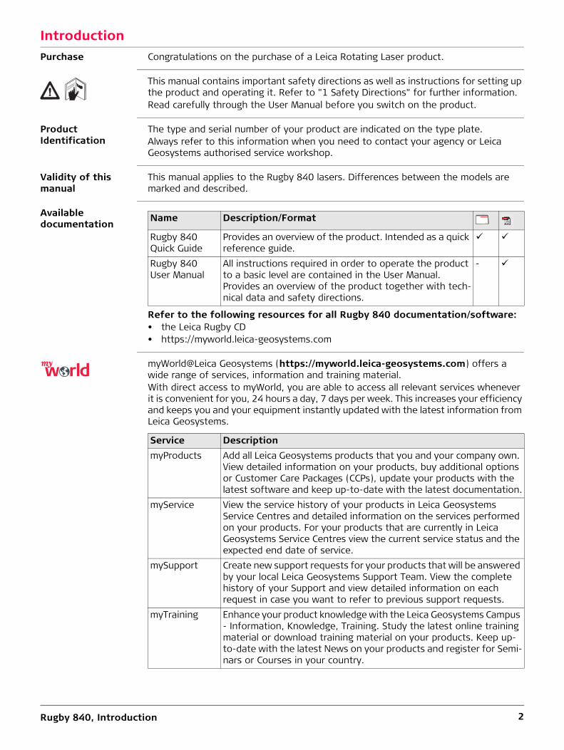
Availabledocumentation
Refer to the following resources for all Rugby 840 documentation/software:• the Leica Rugby CD• https://myworld.leica-geosystems.com
myWorld@Leica Geosystems (https://myworld.leica-geosystems.com) offers a wide range of services, information and training material.With direct access to myWorld, you are able to access all relevant services whenever it is convenient for you, 24 hours a day, 7 days per week. This increases your efficiency and keeps you and your equipment instantly updated with the latest information from Leica Geosystems.
Name Description/Format
Rugby 840 Quick Guide
Provides an overview of the product. Intended as a quick reference guide.
Rugby 840 User Manual
All instructions required in order to operate the product to a basic level are contained in the User Manual. Provides an overview of the product together with tech-nical data and safety directions.
-
Service DescriptionmyProducts Add all Leica Geosystems products that you and your company own.
View detailed information on your products, buy additional options or Customer Care Packages (CCPs), update your products with the latest software and keep up-to-date with the latest documentation.
myService View the service history of your products in Leica Geosystems Service Centres and detailed information on the services performed on your products. For your products that are currently in Leica Geosystems Service Centres view the current service status and the expected end date of service.
mySupport Create new support requests for your products that will be answered by your local Leica Geosystems Support Team. View the complete history of your Support and view detailed information on each request in case you want to refer to previous support requests.
myTraining Enhance your product knowledge with the Leica Geosystems Campus - Information, Knowledge, Training. Study the latest online training material or download training material on your products. Keep up-to-date with the latest News on your products and register for Semi-nars or Courses in your country.

Rugby 840, Introduction 3
myTrustedServices
Offers increased productivity while at the same time providing maximum security.• myExchange
With myExchange you can exchange any files/objects from your computer to any of your Leica Exchange Contacts.
• mySecurityIf your instrument is ever stolen, a locking mechanism is available to ensure that the instrument is disabled and can no longer be used.
Service Description

Rugby 840, Table of Contents 4
Table of ContentsIn this manual Chapter Page
1 Safety Directions 61.1 General 61.2 Definition of Use 71.3 Limits of Use 71.4 Responsibilities 71.5 Hazards of Use 81.6 Laser Classification 10
1.6.1 General 101.6.2 Rugby 840 10
1.7 Electromagnetic Compatibility EMC 111.8 FCC Statement, Applicable in U.S. 121.9 ICES-003 Statement, Applicable in Canada 13
2 Description of the System 142.1 System Components 142.2 Rugby Laser Components 152.3 Case Components 152.4 Setup 162.5 RC400 Remote Control 17
2.5.1 Pairing the Rugby 840 with the RC400 Remote Control 18
3 Operation 193.1 Buttons 193.2 LED Indicators 203.3 Turning the Rugby on and off 203.4 Automatic Mode 213.5 Manual Mode 213.6 Elevation Alert (H.I.) Function 23
4 RC800 Remote Control and Semi-Automatic Grade 244.1 RC800 Remote Control 24
4.1.1 Description of the Remote Control 244.1.2 Pairing the Rugby with the RC800 Remote Control 254.1.3 Connecting Screen for the Remote Control 25
4.2 Operation 264.2.1 Start Up Screens 264.2.2 Grade Entry 274.2.3 Elevation (H.I.) Alert, Bump Alert and Smart Slope
Functions 284.2.4 Rugby Menu Options 304.2.5 RC800 Menu 32
5 Receiver 335.1 Rod Eye 180, Digital RF Receiver (used with the Rugby 840) 335.2 Menu 345.3 Pairing the Rod Eye 180 with the Rugby 840 34

Rugby 840, Table of Contents 5
6 Applications 356.1 Setting Forms 356.2 Checking Grades 366.3 Manual Grades 376.4 Applications - Rugby 840 and the Rod Eye 180 Digital RF
receiver 386.4.1 Smart Target (Automatic Slope Catching) 386.4.2 Smart Target Lock (Slope Lock/Monitoring) 396.4.3 Dual Receiver Setups 406.4.4 Batter Boards 416.4.5 Facades 436.4.6 Suspended Ceilings 456.4.7 Layout 46
6.5 Rugby and the RC800 Remote Control 486.5.1 Entering Grades 48
7 Batteries 507.1 Operating Principles 507.2 Battery for Rugby 51
8 Accuracy Adjustment 548.1 Checking the Level Accuracy 548.2 Adjusting the Level Accuracy 55
9 Automatic Field Calibration 57
10 Troubleshooting 6010.1 Rugby 840 6010.2 RC800 Remote Control 62
11 Care and Transport 6411.1 Transport 6411.2 Storage 6411.3 Cleaning and Drying 65
12 Technical Data 6612.1 Conformity to National Regulations 66
12.1.1 Rugby 840 6612.1.2 Dangerous Goods Regulations 66
12.2 General Technical Data of the Laser 6712.3 RC400 Remote Control 6812.4 RC800 Remote Control 69
13 Warranty under PROTECT by Leica Geosystems 70
14 Accessories 71
Index 73

Rugby 840, Safety Directions 6
1 Safety Directions1.1 General
Description The following directions enable the person responsible for the product, and the person who actually uses the equipment, to anticipate and avoid operational hazards.
The person responsible for the product must ensure that all users understand these directions and adhere to them.
About Warning Messages
Warning messages are an essential part of the safety concept of the instrument. They appear wherever hazards or hazardous situations can occur.
Warning messages...• make the user alert about direct and indirect hazards concerning the use of the
product.• contain general rules of behaviour.
For the users‘ safety, all safety instructions and safety messages shall be strictly observed and followed! Therefore, the manual must always be available to all persons performing any tasks described herein.
DANGER, WARNING, CAUTION and NOTICE are standardized signal words for iden-tifying levels of hazards and risks related to personal injury and property damage. For your safety it is important to read and fully understand the table below with the different signal words and their definitions! Supplementary safety information symbols may be placed within a warning message as well as supplementary text.
Type Description
� DANGER Indicates an imminently hazardous situation which, if not avoided, will result in death or serious injury.
� WARNING Indicates a potentially hazardous situation or an unintended use which, if not avoided, could result in death or serious injury.
� CAUTION Indicates a potentially hazardous situation or an unintended use which, if not avoided, may result in minor or moderate injury.
NOTICE Indicates a potentially hazardous situation or an unintended use which, if not avoided, may result in appreciable material, financial and environmental damage.
Important paragraphs which must be adhered to in practice as they enable the product to be used in a technically correct and efficient manner.

Rugby 840, Safety Directions 7
1.2 Definition of Use
Intended use • The product casts a horizontal laser plane or a laser beam for the purpose of align-ment.
• The laser beam can be detected by means of a laser detector.• Remote control of product.• Data communication with external appliances.
Reasonably fore-seeable misuse
• Use of the product without instruction.• Use outside of the intended use and limits.• Disabling safety systems.• Removal of hazard notices.• Opening the product using tools, for example screwdriver, unless this is permitted
for certain functions.• Modification or conversion of the product.• Use after misappropriation.• Use of products with obvious damages or defects.• Use with accessories from other manufacturers without the prior explicit approval
of Leica Geosystems.• Inadequate safeguards at the working site.• Deliberate dazzling of third parties.• Controlling of machines, moving objects or similar monitoring application without
additional control and safety installations.
1.3 Limits of Use
Environment Suitable for use in an atmosphere appropriate for permanent human habitation: not suitable for use in aggressive or explosive environments.
� DANGER Local safety authorities and safety experts must be contacted before working in hazardous areas, or close to electrical installations or similar situations by the person in charge of the product.
1.4 Responsibilities
Manufacturer of the product
Leica Geosystems AG, CH-9435 Heerbrugg, hereinafter referred to as Leica Geosys-tems, is responsible for supplying the product, including the user manual and original accessories, in a safe condition.
Person responsible for the product
The person responsible for the product has the following duties:• To understand the safety instructions on the product and the instructions in the
user manual.• To ensure that it is used in accordance with the instructions.• To be familiar with local regulations relating to safety and accident prevention.• To inform Leica Geosystems immediately if the product and the application
becomes unsafe.• To ensure that the national laws, regulations and conditions for the operation of
e.g. radio transmitters or lasers are respected.

Rugby 840, Safety Directions 8
1.5 Hazards of Use
� CAUTION Watch out for erroneous measurement results if the product has been dropped or has been misused, modified, stored for long periods or transported.Precautions:Periodically carry out test measurements and perform the field adjustments indicated in the user manual, particularly after the product has been subjected to abnormal use as well as before and after important measurements.
� DANGER Because of the risk of electrocution, it is dangerous to use poles, levelling staffs and extensions in the vicinity of electrical installations such as power cables or electrical railways.Precautions:Keep at a safe distance from electrical installations. If it is essential to work in this environment, first contact the safety authorities responsible for the electrical instal-lations and follow their instructions.
NOTICE With the remote control of products, it is possible that extraneous targets will be picked out and measured.Precautions:When measuring in remote control mode, always check your results for plausibility.
� WARNING If the product is used with accessories, for example masts, staffs, poles, you may increase the risk of being struck by lightning.Precautions:Do not use the product in a thunderstorm.
� WARNING Inadequate securing of the working site can lead to dangerous situations, for example in traffic, on building sites and at industrial installations.Precautions:Always ensure that the working site is adequately secured. Adhere to the regulations governing safety, accident prevention and road traffic.
� CAUTION If the accessories used with the product are not properly secured and the product is subjected to mechanical shock, for example blows or falling, the product may be damaged or people can sustain injury.Precautions:When setting-up the product, make sure that the accessories are correctly adapted, fitted, secured, and locked in position.Avoid subjecting the product to mechanical stress.
� WARNING During the transport, shipping or disposal of batteries it is possible for inappropriate mechanical influences to constitute a fire hazard.Precautions:Before shipping the product or disposing of it, discharge the batteries by running the product until they are flat.When transporting or shipping batteries, the person in charge of the product must ensure that the applicable national and international rules and regulations are observed. Before transportation or shipping contact your local passenger or freight transport company.

Rugby 840, Safety Directions 9
� WARNING During dynamic applications, for example stakeout procedures there is a danger of accidents occurring if the user does not pay attention to the environmental conditions around, for example obstacles, excavations or traffic.Precautions:The person responsible for the product must make all users fully aware of the existing dangers.
� WARNING If you open the product, either of the following actions may cause you to receive an electric shock.• Touching live components• Using the product after incorrect attempts were made to carry out repairsPrecautions:Do not open the product. Only Leica Geosystems authorised service workshops are entitled to repair these products.
� WARNING If the product is improperly disposed of, the following can happen:• If polymer parts are burnt, poisonous gases are produced which may impair health.• If batteries are damaged or are heated strongly, they can explode and cause
poisoning, burning, corrosion or environmental contamination.• By disposing of the product irresponsibly you may enable unauthorised persons to
use it in contravention of the regulations, exposing themselves and third parties to the risk of severe injury and rendering the environment liable to contamination.
Precautions:
Product-specific treatment and waste management information can be downloaded from the Leica Geosystems home page at http://www.leica-geosystems.com/treatment or received from your Leica Geosystems distributor.
� WARNING Only Leica Geosystems authorised service workshops are entitled to repair these prod-ucts.
� WARNING High mechanical stress, high ambient temperatures or immersion into fluids can cause leakage, fire or explosions of the batteries.Precautions:Protect the batteries from mechanical influences and high ambient temperatures. Do not drop or immerse batteries into fluids.
� WARNING If battery terminals are short circuited e.g. by coming in contact with jewellery, keys, metalized paper or other metals, the battery can overheat and cause injury or fire, for example by storing or transporting in pockets.Precautions:Make sure that the battery terminals do not come into contact with metallic objects.
The product must not be disposed with household waste.Dispose of the product appropriately in accordance with the national regulations in force in your country.Always prevent access to the product by unauthorised personnel.
Rugby 840, Safety Directions 10
1.6 Laser Classification1.6.1 General
General The following chapters provide instructions and training information about laser safety according to international standard IEC 60825-1 (2014-05) and technical report IEC TR 60825-14 (2004-02). The information enables the person responsible for the product and the person who actually uses the equipment, to anticipate and avoid operational hazards.
1.6.2 Rugby 840
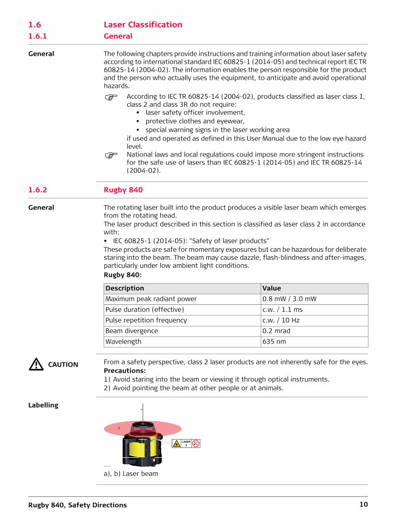
General The rotating laser built into the product produces a visible laser beam which emerges from the rotating head.The laser product described in this section is classified as laser class 2 in accordance with:• IEC 60825-1 (2014-05): "Safety of laser products"These products are safe for momentary exposures but can be hazardous for deliberate staring into the beam. The beam may cause dazzle, flash-blindness and after-images, particularly under low ambient light conditions.Rugby 840:
� CAUTION From a safety perspective, class 2 laser products are not inherently safe for the eyes.Precautions:1) Avoid staring into the beam or viewing it through optical instruments.2) Avoid pointing the beam at other people or at animals.
Labelling
According to IEC TR 60825-14 (2004-02), products classified as laser class 1, class 2 and class 3R do not require:
• laser safety officer involvement,• protective clothes and eyewear,• special warning signs in the laser working area
if used and operated as defined in this User Manual due to the low eye hazard level.
National laws and local regulations could impose more stringent instructions for the safe use of lasers than IEC 60825-1 (2014-05) and IEC TR 60825-14 (2004-02).
Description ValueMaximum peak radiant power 0.8 mW / 3.0 mWPulse duration (effective) c.w. / 1.1 msPulse repetition frequency c.w. / 10 HzBeam divergence 0.2 mradWavelength 635 nm
a), b) Laser beam004787_002
bb
a
Rugby 840, Safety Directions 11
1.7 Electromagnetic Compatibility EMC
Description The term Electromagnetic Compatibility is taken to mean the capability of the product to function smoothly in an environment where electromagnetic radiation and electro-static discharges are present, and without causing electromagnetic disturbances to other equipment.
� WARNING Electromagnetic radiation can cause disturbances in other equipment.Although the product meets the strict regulations and standards which are in force in this respect, Leica Geosystems cannot completely exclude the possibility that other equipment may be disturbed.
� CAUTION There is a risk that disturbances may be caused in other equipment if the product is used with accessories from other manufacturers, for example field computers, personal computers or other electronic equipment, non-standard cables or external batteries.Precautions:Use only the equipment and accessories recommended by Leica Geosystems. When combined with the product, they meet the strict requirements stipulated by the guide-lines and standards. When using computers or other electronic equipment, pay atten-tion to the information about electromagnetic compatibility provided by the manufac-turer.
� CAUTION Disturbances caused by electromagnetic radiation can result in erroneous measure-ments.Although the product meets the strict regulations and standards which are in force in this respect, Leica Geosystems cannot completely exclude the possibility that the product may be disturbed by intense electromagnetic radiation, for example, near radio transmitters, two-way radios or diesel generators.Precautions:Check the plausibility of results obtained under these conditions.
� CAUTION If the product is operated with connecting cables attached at only one of their two ends, for example external supply cables, interface cables, the permitted level of elec-tromagnetic radiation may be exceeded and the correct functioning of other products may be impaired. Precautions:While the product is in use, connecting cables, for example product to external battery, product to computer, must be connected at both ends.
Radios or Digital Cellular Phones
Use of product with radio or digital cellular phone devices:
� WARNING Electromagnetic fields can cause disturbances in other equipment, in installations, in medical devices, for example pacemakers or hearing aids and in aircraft. It can also affect humans and animals.Precautions:Although the product meets the strict regulations and standards which are in force in this respect, Leica Geosystems cannot completely exclude the possibility that other equipment can be disturbed or that humans or animals can be affected.• Do not operate the product with radio or digital cellular phone devices in the vicinity
of filling stations or chemical installations, or in other areas where an explosion hazard exists.
• Do not operate the product with radio or digital cellular phone devices near to medical equipment.
• Do not operate the product with radio or digital cellular phone devices in aircraft.

Rugby 840, Safety Directions 12
1.8 FCC Statement, Applicable in U.S.
The greyed paragraph below is only applicable for products without radio.
� WARNING
� WARNING Changes or modifications not expressly approved by Leica Geosystems for compliance could void the user's authority to operate the equipment.
Labelling Rugby 840
Labelling Rod Eye
This equipment has been tested and found to comply with the limits for a Class B digital device, pursuant to part 15 of the FCC rules.These limits are designed to provide reasonable protection against harmful interfer-ence in a residential installation.This equipment generates, uses and can radiate radio frequency energy and, if not installed and used in accordance with the instructions, may cause harmful interference to radio communications. However, there is no guarantee that interference will not occur in a particular installation.If this equipment does cause harmful interference to radio or television reception, which can be determined by turning the equipment off and on, the user is encouraged to try to correct the interference by one or more of the following measures:• Reorient or relocate the receiving antenna.• Increase the separation between the equipment and the receiver.• Connect the equipment into an outlet on a circuit different from that to which the
receiver is connected.• Consult the dealer or an experienced radio/TV technician for help.
Complies with FDA performance standards forlaser products except for deviations pursuant to
Laser Notice Nr. 50 July 24, 2007
This device complies with part 15 of the FCC Rules. Operation is subject to the following
two conditions: (1) This device may not cause harmful interference, and (2) This
device must accept any interferencereceived, including interference that
may cause undesired operation.
Leica Geosystems AGCH-9435 Heerbrugg
Serial Number: YWWY8402500
Y W W Y 8 7 0 2 5 0 0
pPav = 3.0-0.8mW λ = 635nm t = 1.1ms - cwClass 2 Laser - IEC 60825-1:2014
Type: Rugby 840Power: 8.4V / 0.5A / Art.No.: 795434Made in China / Manufactured: MM/YYYY
Contains FCC ID: RFD-CT100 IC: 3177A-CT100
004788_002
Rod Eye 180
This device complies with part 15 of the FCC Rules. Operation issubject to the following two conditions:(1) This device may not cause harmful interference, and(2) this device must accept any interference received, includinginterference that may cause undesired operation.
CH-9435 Heerbrugg
Swiss Technologyby Leica GeosystemsPower : 3V / 100mA
Art.No.: 832396Made in ChinaContains FCC ID: RFD-CT100 IC ID: 3177A-CT100
Type: RE180A
004662_002
Rugby 840, Safety Directions 13
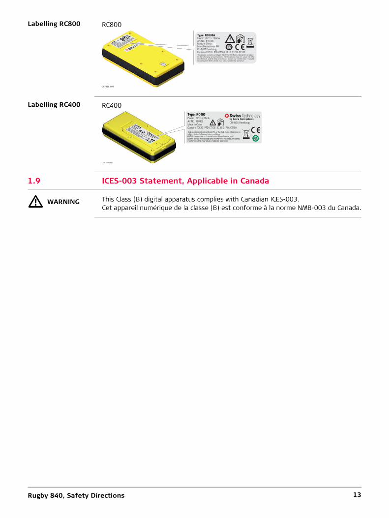
Labelling RC800
Labelling RC400
1.9 ICES-003 Statement, Applicable in Canada
� WARNING This Class (B) digital apparatus complies with Canadian ICES-003.Cet appareil numérique de la classe (B) est conforme à la norme NMB-003 du Canada.
RC800
007818_002
This device complies with part 15 of the FCC Rules. Operation is subjectto the following two conditions: (1) This device may not cause harmfulinterference, and (2) this device must accept any interference received,including interference that may cause undesired operation.
Type: RC800APower : 3V / 100mAArt.No.: 840706Made in ChinaLeica Geosystems AGCH-9435 HeerbruggContains FCC ID: RFD-CT300 IC ID: 3177A-CT300
RC400
This device complies with part 15 of the FCC Rules. Operation issubject to the following two conditions:(1) This device may not cause harmful interference, and(2) this device must accept any interference received, includinginterference that may cause undesired operation.
CH-9435 Heerbrugg
Swiss Technologyby Leica GeosystemsPower : 3V / 60mA
Art.No.: 790352Made in ChinaContains FCC ID: RFD-CT100 IC ID: 3177A-CT100
Type: RC400
004789_001
Rugby 840, Description of the System 14
2 Description of the System2.1 System Components
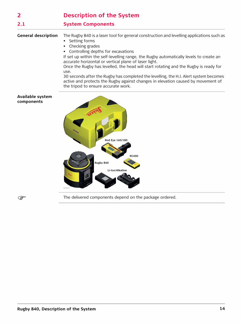
General description The Rugby 840 is a laser tool for general construction and levelling applications such as• Setting forms• Checking grades• Controlling depths for excavationsIf set up within the self-levelling range, the Rugby automatically levels to create an accurate horizontal or vertical plane of laser light.Once the Rugby has levelled, the head will start rotating and the Rugby is ready for use. 30 seconds after the Rugby has completed the levelling, the H.I. Alert system becomes active and protects the Rugby against changes in elevation caused by movement of the tripod to ensure accurate work.
Available system components
The delivered components depend on the package ordered.
004790 001
Rod Eye 160/180
Rugby 840
Li-Ion/Alkaline
RC400

Rugby 840, Description of the System 15
2.2 Rugby Laser Components
Rugby laser components
2.3 Case Components
Case components
a) Carry Handleb) LED Indicatorsc) Buttonsd) Battery compartmente) Charge jack (for Li-Ion
battery pack)004791_001
ab
c
d
e
a) Rugby laserb) Rod eye receiver mounted on the bracketc) Li-Ion battery pack or Alkaline battery packd) RC400 Remote Controle) 2x AA-cell batteryf) User Manual/CDg) Second receiver (can be purchased separately)h) 4 x D-cell battery (for alkaline versions only)i) Charger (for Li-Ion versions only)
004792_001
a
bc
e
fg
h
i
d
Rugby 840, Description of the System 16
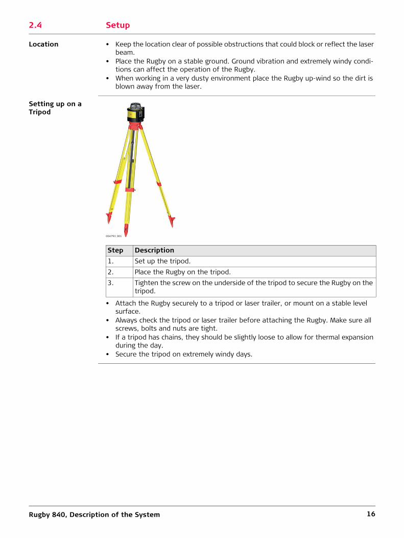
2.4 Setup
Location • Keep the location clear of possible obstructions that could block or reflect the laser beam.
• Place the Rugby on a stable ground. Ground vibration and extremely windy condi-tions can affect the operation of the Rugby.
• When working in a very dusty environment place the Rugby up-wind so the dirt is blown away from the laser.
Setting up on a Tripod
• Attach the Rugby securely to a tripod or laser trailer, or mount on a stable level surface.
• Always check the tripod or laser trailer before attaching the Rugby. Make sure all screws, bolts and nuts are tight.
• If a tripod has chains, they should be slightly loose to allow for thermal expansion during the day.
• Secure the tripod on extremely windy days.
Step Description1. Set up the tripod.2. Place the Rugby on the tripod.3. Tighten the screw on the underside of the tripod to secure the Rugby on the
tripod.
004793_001

Rugby 840, Description of the System 17
2.5 RC400 Remote Control
Description The RF Remote Control communicates with the Rugby via RC (radio) and is used to control the same functions as on the laser.
RC400 Remote Control panel
Description of the Buttons
Sending LED:The sending LED flashes to indicate that the remote is sending a signal to the Rugby.
The remote control is powered by a 2x AA batteries. replacement is the same as for the Rod Eye receivers.
a) Sending LEDb) Scan mode buttonc) Left and Right Arrow buttonsd) Up and Down Arrow buttonse) Clockwise (CW) and Counterclock-
wise (CCW) buttonsf) Scan 90° and Scan Memory buttong) Head Speed buttonh) Automatic/Manual Mode button i) Beam down buttonj) Sleep mode button
004794_001
a
bcdef
g
h
i
c
e
j
Button FunctionScan Mode Press to change width of the scanning motion.Left and Right Arrow
Press to tilt the Y-axis when it is in Manual Mode. In the laydown position press to align the vertical plane and 90° split beam.
Up and Down Press to tilt the X-axis when it is in Manual Mode.CW and CCW Press to rotate the stationary and scanning beam in a clockwise
or counterclockwise motion.Scan 90° and Scan Memory
Press to quickly move the scanning or stationary beam at 90° intervals. In Scan Mode the scan width will automatically change to the smallest scan width when this function is activated.
Scan Memory means that you can switch to rotational or stationary mode and the scan will return to the previous position when scanning motion is chosen again.
Head Speed Press to change the speed of the head rotation.Automatic/Manual Mode
Press to change desired axis to Manual Mode.
Beam down Press to stop the rotating head (zero rps). The position of the beam will move to the downward position to allow the user to align the Rugby over a reference point on the floor.
Sleep mode Press to put the Rugby in sleep mode.• During Sleep Mode all functions are disabled.• The Low battery indicator flashes once every ten seconds to
indicate the Rugby is in Sleep Mode.• The Rugby will sleep for two hours, then shuts down auto-
matically and must be turned on again at the laser.• When in Sleep Mode pressing the sleep button will wake the
Rugby and normal operation resumes.

Rugby 840, Description of the System 18
Applications • For layout work use the Beam down feature to position the beam over a reference point. Then use the Scan 90° feature to quickly move the small scan to a position to the left or right of the laser.
• For ceiling applications and marking elevations the Scan 90° feature can quickly bring the scanning beam to you.
2.5.1 Pairing the Rugby 840 with the RC400 Remote Control
Pairing step-by-step The Rugby 840 and the RC400 Remote Control include radio devices that allow the user to activate additional functions on the Rugby. When purchased together, the Rugby 840 and the RC400 have been paired together at the factory. Should it be necessary to pair your units after purchase, the following information is applicable.Before using the RF features, the Rugby and the Remote Control must first be paired together to be able to communicate with each other.
Refer to "5.3 Pairing the Rod Eye 180 with the Rugby 840" for information on pairing the Rugby with the receiver.
Step Description1. Turn off the Rugby 840.2. Press and hold the Power button on the Rugby 840 for 5 seconds to turn on
the Rugby 840 in pairing mode. The Rugby 840 beeps five times.3. Press and hold the Head Speed button and the Scan Mode button on the
RC400.
The X-axis Indicator LED and the Y-axis Indicator LED flash green and the Rugby 840 beeps five times quickly when the pairing was successful.The X-axis Indicator LED and the Y-axis Indicator LED flash red five times quickly if the pairing was not successful.

Rugby 840, Operation 19
3 Operation3.1 Buttons
Buttons
Description of the Buttons
a) Left and Right Arrow buttonsb) Scanning buttonc) Power buttond) Automatic/Manual Mode buttone) Head speed button (rps)004795_001
a a
b
c
d
e
Button FunctionLeft and Right Arrow
Press to enter a slope for an axis in Manual Mode.
Power Press to turn on or off the Rugby.Automatic/Manual Mode
Press once to change the X-axis to Manual Mode with Y-axis self-levelling.Press again to change the Y-axis to Manual Mode with X-axis self-levelling.Press again to change both axes to Manual Mode with no self-levelling.Press again to change back to Full Automatic Mode.
Note the changes in the LED indicators in the Manual Modes. The red LED indicates that the corresponding axis is in Manual Mode.
Scanning Press to change the width of the scanning beam - 10° • 45° • 90°Head Speed Press to change the speed of the head rotation - 0 • 2 • 5 rps

Rugby 840, Operation 20
3.2 LED Indicators
Main Functions DescriptionThe LED Indicators have three main functions:• To indicate the level status of the axes.• To indicate the battery status.• To indicate an H.I. Alert condition.Diagram of the LED Indicators
Description of the LEDs
3.3 Turning the Rugby on and off
Turning on and off Press the Power button to turn on or off the Rugby.After turning on: • If set up within the +/-6° self-levelling range (horizontal or vertical), the Rugby
automatically levels to create an accurate horizontal plane of laser light.• Once levelled, the head starts rotating and Rugby is ready for use.• After 30 seconds of completing the levelling, the H.I. Alert system becomes active
to protect the laser against changes in elevation caused by movement or settling of the tripod.
• The self-levelling system and H.I. Alert function continues to monitor the position of the laser beam to ensure consistent and accurate work.
a) Low Battery Indicator LEDb) X-axis Indicator LEDc) Y-axis Indicator LED004796_001
ab c
IF the is/are THENLow Battery Indicator LED (Li-Ion)
off the battery is okay.flashing slowly the battery has ≤ 10% (4 h) power
remaining.flashing quickly the battery has ≤ 5% (2 h) power remaining.red the battery cannot power the Rugby. Charge
the battery.Low Battery Indicator LED (alkaline)
off the battery is okay.flashing slowly the battery is getting low.flashing rapidly the battery needs to be changed.
X-axis and Y-axis Indi-cator LEDs
green the axis is level.flashing green the axis is levelling.red the axis is in Manual Mode.both flashing red
an H.I. Alert is indicated.

Rugby 840, Operation 21
3.4 Automatic Mode
Description of the Automatic Mode
The Rugby always starts up in Automatic Mode.In Automatic Mode the Rugby automatically levels if set up within the 6° self-levelling range (horizontal or vertical).
3.5 Manual Mode
Description of the Manual Mode
After start-up the Manual Mode can be activated. In Manual Mode the self-levelling will be deactivated. The following options are available:• Change the X-axis to Manual Mode• Change the Y-axis to Manual Mode• Change to Full Manual Mode
After turning the Rugby off and on again, the Rugby is in Automatic Mode.
Changing the X-axis to Manual Mode
After startup, press the Automatic/Manual Mode Button once to change the X-axis to Manual Mode.
The X-axis and Y-axis are marked on the top of the Rugby.• The X-axis does not self-level and a slope can be entered in this axis using the Up
and Down Arrow buttons on the Rugby.• The X-axis LED is red.• The Y-axis continues to self-level and the Y-axis
LED flashes green until level.
When the X-axis is in Manual Mode, the X-axis can be sloped upwards or downwards as illustrated.
004797_001

Rugby 840, Operation 22
Changing the Y-axis to Manual Mode
Press the Automatic/Manual Mode button again to change the Y-axis to Manual Mode.
The X-axis and Y-axis are marked on the top of the Rugby.
Changing to Full Manual Mode
Press the Automatic/Manual Mode button again to change to Full Manual Mode.
The X and Y axes are marked on the top of the Rugby.
When using the RC400 Remote Control, each of the axes can be sloped inde-pendently.
• The Y-axis does not self-level and a slope can be entered in this axis using the Up and Down Arrow buttons on the Rugby.
• The Y-axis LED is red.• The X-axis continues to self-level and the X-axis
LED flashes green until level.
When the Y-axis is in Manual Mode, the Y-axis can be sloped upwards or downwards as illustrated.
004798_001
• Both the X-axis and Y-axis do not self-level and a slope can be entered in the Y-axis using the Left and Right Arrow buttons on the Rugby.
• The X-axis LED is red.• The Y-axis LED is red.
When both the X-axis and Y-axis are in Manual Mode, the Y-axis can be sloped using the Left and Right Arrow buttons.
004799_001

Rugby 840, Operation 23
3.6 Elevation Alert (H.I.) Function
Description of the Elevation Alert function
• The Elevation Alert or Height of Instrument (H.I.) function prevents incorrect work caused by movement or settling of the tripod that would cause the laser to level at a lower height.
• The Elevation Alert function becomes active and monitors the movement of the laser 30 second after the Rugby has completely levelled and the head of the laser starts rotating.
• The Elevation Alert monitors the laser. If disturbed, both the X-axis LED and Y-axis LED flash and the Rugby beeps rapidly.
• To stop the alert turn Rugby off and on again. Check the height of the laser before beginning to work again.
The Elevation Alert function turns on automatically every time the Rugby is turned on.
Disable or enable the Elevation Alert function
The Elevation Alert function can be disabled or enabled by pressing the following button combination: • With the Rugby turned on, press and hold the Left and Right Arrow buttons.• Press the Automatic/Manual Mode button.
The Rugby beeps once to indicate the change.

Rugby 840, RC800 Remote Control and Semi-Automatic Grade 24
4 RC800 Remote Control and Semi-Automatic Grade4.1 RC800 Remote Control4.1.1 Description of the Remote Control
The RF Remote Control communicates with the Rugby via RF (radio frequency).When the Rugby is used together with the RC800 remote (type 800A), the Rugby will operate as an semi-automatic grade laser, allowing the user to dial in a desired grade value.
RC400 Remote Control
Description of the Control Panel
* In the Remote Control menu, you can select the sleep time.
a) LCD displayb) Power buttonc) Remote battery LEDd) Grade buttone) Left and right arrow buttonsf) Rugby LEDg) Sleep mode buttonh) Up and down arrow buttons007830_002
abc
de
fg
h
e
LCD Display Displays all required user information.Power Button Press to turn on or off the Remote Control.Grade Button Press to start grade entry mode.Up and Down Arrow Buttons
Press to change the grade displayed.Press both simultaneously to reset the grade value to zero.
Left and Right Arrow Buttons
Press both simultaneously to enter the Rugby menu.Press and hold simultaneously for 1.5 seconds to enter the Remote Control menu.
Sleep Mode Button Press to put the Rugby in sleep mode.• During Sleep Mode, all functions are disabled.• The LCD display indicates that the Rugby is in Sleep
Mode.• The Rugby sleeps for 2 hours*, then shuts down auto-
matically and must be turned on again at the laser.• When in Sleep Mode, pressing the sleep button wakes
the Rugby and normal operation is resumed.Rugby LED Indicates level status of the Rugby.Remote Battery LED Indicates when the batteries for the Remote Control
should be replaced.

Rugby 840, RC800 Remote Control and Semi-Automatic Grade 25
Replacing the batteries The remote control is powered by 2x AA batteries.
If the Remote Battery LED flashes, replace the batteries as shown in the picture.
4.1.2 Pairing the Rugby with the RC800 Remote Control
Pairing step-by-step The Rugby and the RC800 Remote Control include radio devices that allow you to acti-vate the functions on the Rugby remotely up to 100 m (330’) from the Rugby. Before using the RF features, the Rugby and the Remote Control must be paired together to be able to communicate with each other.
4.1.3 Connecting Screen for the Remote Control
Information screen while connecting
007831_001
1
2
3a
3b
Step Description1. Turn off both the Rugby and the Remote Control.2. Press and hold the Power Button on the Rugby for 5 seconds to turn on the
Rugby in pairing mode. The Rugby beeps five times slowly.3. Press and hold the Power Button on the Remote Control until pairing is
confirmed.
When the pairing is successful: Both the Rugby and the Remote Control beep quickly five times and the Status LED flashes green quickly (5 Hz). There is no confirmation on the LCD displays during this process.
When the pairing is not successful:Both the Rugby and the Remote Control beep slowly three times and the Status LED flashes red (1 Hz).
Connecting Screen The "connecting” screen is displayed when the Remote Control is first turned on and while connecting to the Rugby.
007599_001

Rugby 840, RC800 Remote Control and Semi-Automatic Grade 26
4.2 Operation4.2.1 Start Up Screens
Start up screen
Main user screen
Grade mode screen
When the Rugby is turned on, the Leica Start up screen is shown displaying the following information:• Serial number (Rugby)• Software revision level (RC800)
Start up screen - RC800011078_001
The Main user screens show the grade input.
011079_001
Enter your desired grade in Grade mode. The Rugby will check the level position and then adjust the plane of laser light to the grade input.
In Grade mode, the Rugby does not self-level, but is set to detect bumps and temperature changes.
A small icon in the bottom left of the screen indicates that the axis with grade is not self-levelling.
011080_001

Rugby 840, RC800 Remote Control and Semi-Automatic Grade 27
4.2.2 Grade Entry
Entering grade
Grade setting process
The Rugby always starts up with no grade input.
To enter grade, do the following:1) Press the Grade button once to enter
Grade mode.2) Press the Up and Down arrow buttons to
enter a grade for the X-axis.3) Press the Grade button a second time to
switch to the Y-axis.4) Press the Up and Down arrow buttons to
enter a grade for the Y-axis.5) Press the Grade button again to return to
the Main user screen.The Rugby will begin the grade setting process.
The smallest grade increment is 0.05% up to 3.00% grade and 0.10% for grade greater than 3.00%.
When entering grade the displays change as shown.
To restore the last set grade(s), press and hold the Grade button for 1.5 seconds.
If after eight seconds no button is pressed, the Rugby will accept the grade entered and will begin the grade setting process.
X-axis grade entry
Y-axis grade entry
011081_001
011082_001
After grade entry for one or both axes, the Rugby waits for 8 seconds of no movement or button presses before beginning the process.The Rugby then displays the Levelling to grade screen and automatically self-levels in the horizontal plane, followed by readjusting the servo mechanism to the desired grade value.After completion, the Rugby activates the Slope/Bump Alert and Temperature Alert functions (if enabled).
During this process, do not touch or disturb the Rugby.
Levelling to grade screen011083_001

Rugby 840, RC800 Remote Control and Semi-Automatic Grade 28
4.2.3 Elevation (H.I.) Alert, Bump Alert and Smart Slope Functions
Elevation (H.I.) Alert
The Elevation Alert or Height of Instrument (H.I) function prevents incorrect work caused by movement or settling of the tripod that would cause the Rugby to level at a lower height.The Elevation (H.I.) Alert function becomes active and monitors the movement of the Rugby 30 seconds after it has completely levelled and the head starts rotating.If the Rugby gets disturbed, the Elevation (H.I.) Alert screen is displayed and the Rugby beeps rapidly.
To stop the alert, turn the Rugby off and on again. Check the height of the laser before beginning to work again.
The Elevation (H.I.) Alert functions in Level mode (0.00%) and in Grade mode when one of the axes remains at 0.00%.
The Elevation (H.I.) Alert function turns on automatically every time the Rugby is turned on. It can be enabled/disabled in the Option Menu (enabled by default).
Elevation (H.I.) Alert screen011084_001

Rugby 840, RC800 Remote Control and Semi-Automatic Grade 29
Bump Alert
Smart Slope
The Bump Alert function prevents incorrect work caused by movement or settling of the tripod that occurs when the Rugby is used for grade.The Bump Alert function becomes active and monitors the movement of the Rugby when it has completely levelled and the head starts rotating.If the Rugby gets disturbed, the Bump Alert screen is displayed and the Rugby beeps rapidly.
To stop the alert, do one of the following:• If the height has not changed, press the
Grade button for 1.5 seconds to stop the alert and continue working.The Rugby will check level and return to desired grade.
• If the height has changed, turn the Rugby off and on again, check the height of the laser and reenter the grade.
If one axis is still set to Level mode (0.00%), the Elevation (H.I.) Alert function is also active for this axis.
The Bump Alert function turns on automatically every time grade is entered in the Rugby. It can be enabled/disabled in the Option Menu (enabled by default).
The Bump Alert function can be set to FINE or COARSE in the Option Menu (FINE by default).
Bump Alert screen011085_001
If the Rugby detects a change in ambient temperature, the grade mechanism will return to level position, check level and return to the grade set.During this, the Rugby cannot be used and the Smart Slope screen is displayed.
There are two settings for the Smart Slope function:• FINE: 2°C temperature change /
10 minutes• COARSE: 5°C temperature change /
20 minutes
The Smart Slope setting can be changed in the Option Menu (COARSE by default).
Smart Slope screen: COARSE011086_001

Rugby 840, RC800 Remote Control and Semi-Automatic Grade 30
4.2.4 Rugby Menu Options
Option Menu
Selecting an option
Changing an option
To access the menu of the Rugby, press the left and right arrow button on the RC800 simultaneously while the main screen is displayed.
There are five options available:• Smart Slope: FINE/COARSE/OFF• Bump Alert: FINE/COARSE/OFF• H.I. Alert: ON/OFF at start up• Contrast• Percent/Per mil
011087_001
1) Press the Up arrow or Down arrow button to highlight the option to change.
2) Press the Grade button to enter the selected option screen.
011088_001
1) Press the Up arrow or Down arrow button to highlight the desired option.
2) Press the Grade button to confirm the setting and return to the Option Menu.
011089_001

Rugby 840, RC800 Remote Control and Semi-Automatic Grade 31
Percent/Per mil Do not change this option unless you are sure you want to work with Per mil values (Percent by default).
Changing from Percent to Per mil moves the decimal point one place to the right:• Percent: 1 m per 100 m• Per mil: 1 m per 1,000 m (1 mm per 1 m)
Percent/Per mil option
If changing from Percent to Per mil, confirmation for the change is neces-sary.
Confirm Percent
Percent The Percent and Per mil screens to the left are equal.
Per mil
011090_001
011091_001
011092_001
011093_001

Rugby 840, RC800 Remote Control and Semi-Automatic Grade 32
4.2.5 RC800 Menu
Overview
Display Brightness
Sleep Mode Hours
Remote Shut-Off Time
Remote Control Menu Screen
The RC800 Remote Control has its own menu where you can change the following parameters:• Display Brightness• Sleep Mode Hours• Remote Shut-Off Time
To access the Remote Control menu, press and hold the Left and Right Arrow Buttons on the remote control for 1.5 seconds.
For navigation within the Remote Control menu, use the same buttons as for navigation within the Rugby menu. (Refer to "3.1 Buttons")
007650_001
Remote Control Display Brightness
You can change the display brightness on this screen.Use the Up and Down Arrow Buttons to adjust the bright-ness as desired.
007651_001
Sleep Mode Hours
You can determine how long the Rugby stays in sleep mode before turning off completely:• 2 hours• 4 hours• 8 hours• 16 hours
007652_001
Shut-Off Time
You can determine a shut-off time for the remote control:• 30 seconds• 60 seconds• 120 secondsIf the remote control is not used during this time, it shuts off automatically.
007653_001

Rugby 840, Receiver 33
5 Receiver
Description The Rugby 840 is sold with the Rod Eye 180 Digital RF Receiver. Using the Rugby 840 together with the Rod Eye 180 enables the user to perform special functions such as automatic slope catching and monitoring, as well alignment of the vertical plane for batter boards and facade applications.Additional information on the Rod Eye 180 Digital RF Receiver can be found in the indi-vidual user manuals also located on this CD.
5.1 Rod Eye 180, Digital RF Receiver (used with the Rugby 840)
Instrument components
Description of the Buttons
a) Speakerb) LCD Digital Displayc) LED Displayd) Power buttone) Laser man buttonf) Reception windowg) Bandwidth buttonh) Audio buttoni) X and Y buttons004638_001
ab
cde
f
g
h
i
Button FunctionPower Press once to turn on the receiver.
Press 1.5 seconds to turn off the receiver.Laser man Press to capture the digital reading.
Press 1.5 seconds to start the Smart Target functions such as automatic slope catching on the X-axis in the upright mode and automatic vertical plane alignment in the laying down mode.
Bandwidth Press to change detection bandwidths.Audio Press to change the audio output.X and Y Press to select alternate or second axis for slope catching and
slope monitoring.

Rugby 840, Receiver 34
5.2 Menu
Menu access and navigation
To access the menu of the Rod Eye 180 Digital RF Receiver, press the Bandwidth button and Audio button simultaneously.• Use the Bandwidth button and Audio button to change parameters.• Use the Power button to scroll through the menu.
Menu
5.3 Pairing the Rod Eye 180 with the Rugby 840
Pairing step-by-step The Rugby 840 and the Rod Eye 180 include radio devices that allow the user to auto-matically match an existing grade. When purchased together, the Rugby 840 and Rod Eye 180 have been paired together at the factory. If purchasing a second receiver, the Rugby 840 and the Rod Eye 180 must first be paired together to be able to communicate with each other.
Menu Function IndicationUNT Changes the unit of measure for the
digital readout.Units - mm/cm/in/ft
Active unit flashes.LED Changes the brightness of the LED
indicators.LEDs - High/Low/Off
DRO Turns on or off the digital readout. Green LED is on: digital readout is on.Red LED is on: digital readout is off.
DRO flashes.BAT Turns on or off the Laser low battery
indication on the receiver.Green LED is on: Laser low battery icon function is active.Red LED is on: Laser low battery icon function is not active.
Rugby icon flashes.MEM Turns on or off the position memory
function.Green LED is on: function is on.Red LED is on: function is off.
Full down arrow flashes.RPS Measures the head speed of the
laser.
Hold in rotating beam to measure the head speed.
Measured head speed is displayed.
Step Description1. Turn off the Rugby 840 and the Rod Eye 180.2. Press and hold the Power button on the Rugby 840 for 5 seconds to turn on
the Rugby 840 in pairing mode. The Rugby 840 beeps five times.3. Press and hold the Power button on the Rod Eye 180 for 5 seconds.
The X-axis Indicator LED and the Y-axis Indicator LED flash green and the Rugby 840 beeps five times quickly when the pairing was successful.The X-axis Indicator LED and the Y-axis Indicator LED flash red five times quickly if the pairing was not successful.
Rugby 840, Applications 35
6 Applications6.1 Setting Forms
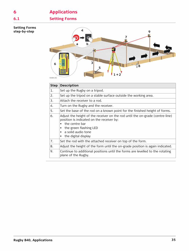
Setting Forms step-by-step
Step Description1. Set up the Rugby on a tripod.2. Set up the tripod on a stable surface outside the working area.3. Attach the receiver to a rod.4. Turn on the Rugby and the receiver.5. Set the base of the rod on a known point for the finished height of forms.6. Adjust the height of the receiver on the rod until the on-grade (centre-line)
position is indicated on the receiver by:• the centre bar• the green flashing LED• a solid audio tone• the digital display
7. Set the rod with the attached receiver on top of the form.8. Adjust the height of the form until the on-grade position is again indicated.9. Continue to additional positions until the forms are levelled to the rotating
plane of the Rugby.
ba
4
004800_001
65
7
8
9
1 + 2
3

Rugby 840, Applications 36
6.2 Checking Grades
Checking Grades step-by-step
Step Description1. Set up the Rugby on a tripod.2. Set up the tripod on a stable surface outside the working area.3. Attach the receiver to a rod.4. Turn on the Rugby and the receiver.5. Set the base of the rod on a known point for the finished grade.6. Adjust the height of the receiver on the rod until the on-grade (centre-line)
position is indicated on the receiver by:• the centre bar• the green flashing LED• a solid audio tone• the digital display
7. Set the rod with the attached receiver on top of the excavation or concrete pour to check for correct elevation.
8. Variances can be read in precise measurements with the digital receiver.• 7a: Position is too high.• 7b: Position is too low. • 7c: Position is on grade.
6
ba
4
004801_001
3
1 + 2
5
7a
7b
7c

Rugby 840, Applications 37
6.3 Manual Grades
Manual Grading step-by-step
Step Description1. Set up the Rugby on a tripod.2. Set up the tripod at the base of a slope with the x-axis pointing in the direction
of the slope.3. Attach the receiver to a rod.4. Turn on the Rugby and the receiver.5. At the base of the slope, adjust the height of the receiver on the rod until the
on-grade (centre-line) position is indicated on the receiver by:• the centre bar• the green flashing LED• a solid audio tone• the digital display
6. Move the rod and the attached receiver to the top of the slope.7. Change the X-axis to Manual Mode by pressing the Automatic/Manual Mode
button once on the Rugby.8. Use the Up and Down Arrow buttons on the Rugby to move the laser beam up
and down until the on-grade (centre-line) position is indicated on the receiver by:• the centre bar• the green flashing LED• a solid audio tone• the digital display
1x
7 8
ba
4
004802_001
5
6
1 + 2
3
X
α
α

Rugby 840, Applications 38
6.4 Applications - Rugby 840 and the Rod Eye 180 Digital RF receiver
Description The Rugby 840 and the Rod Eye 180, Digital Receiver RF, contain radio devices which allow for special features when used together.
6.4.1 Smart Target (Automatic Slope Catching)
Smart Targeting using the Rugby 840, step-by-step
Step Description1. Set up the Rugby 840 at the base of a slope with the X-axis pointing in the
direction of the slope.2. At the base of the slope, adjust the height of the receiver on the rod until the
on-grade (centre-line) position is indicated on the receiver by:• the centre bar• the green flashing LED• a solid audio tone• the digital display
3. Move to the top of the slope and press the laser man button for 1.5 seconds to start the smart targeting process. The receiver shows SMT, then XSC for X-axis slope catching.
4. The Rugby 840 searches for the receiver until the on-grade position is found. Once the on-grade position, the receiver will flash all three LEDs simultane-ously one time and the receiver returns to normal operation.
5. After this signal the receiver can be moved and used as normal. The sloped axis is in Manual mode and should be checked from time to time to ensure the Rugby 840 has not moved.
2
1.5 s
3
4XSC
SMT
004803_001 1
X
α
α

Rugby 840, Applications 39
6.4.2 Smart Target Lock (Slope Lock/Monitoring)
Smart Target Lock using the Rugby 840, step-by-step
Step Description1. Set up the Rugby 840 at the base of a slope with the X-axis pointing in the
direction of the slope.2. At the base of the slope, adjust the height of the Rod Eye 180 Digital Receiver
RF on the rod until the on-grade (centre-line) position is indicated on the receiver by:• the centre bar• the green flashing LED• a solid audio tone• the digital display
3. Move to the top of the slope and press the laser man button for 5 seconds to start the smart target and lock process. The receiver will show SMT, then XSL during the X-axis slope lock process.
4. The Rugby 840 searches for the receiver until the on-grade position is found. Once the on-grade position is found, the receiver will flash all three LEDs simul-taneously one time and the receiver returns to normal operation. The display will show LOC while the receiver is in lock mode.
To turn off lock mode on the receiver, hold the power button for 1.5 seconds.
2
5 s
3
4XSL
SMT
004804_001 1
X
α
α

Rugby 840, Applications 40
6.4.3 Dual Receiver Setups
Dual Receiver setups using the Rugby 840
It is possible to use the Smart Targeting feature of the Rod Eye 180 Digital RF Receiver to catch and monitor both axes of the laser. To do this, perform the actions above for the first axis, and then repeat the actions for the second axis using a second receiver.
To use the Smart Target feature to slope catch and monitor both axes, it is necessary to have two receivers.
Once the lock and monitoring process is started, the receivers must remain in place.
Individual axis can be selected for the Smart Targeting procedure by first pressing the X or Y button on the receiver keypad and the laser man button.
Action ButtonsTo slope catch the X-axis: Press X plus Laser Man for 1.5 seconds
To slope catch and lock the X-axis: Press X plus Laser Man for 5 seconds.
To slope catch the Y axis: Press Y plus Laser Man for 1.5 seconds.
To slope catch and lock the Y-axis: Press Y plus Laser Man for 5 seconds.
1.5 s1x +
5 s1x +
1.5 s1x +
5 s1x +

Rugby 840, Applications 41
6.4.4 Batter Boards
Description The Rugby 840 and the Rod Eye 180 Digital Receiver create a vertical plane of laser light that acts as a virtual string line for batter board setups.
Setup Laser setup
Receiver setup
Step Description1. Mount the Rugby to the clamp and then the clamp to the batter board.2. Turn on the Rugby.
The laser beam will automatically point downwards so that the laser and the clamp can be positioned directly over the surveyed reference nail.
3. Set the head rotation to the fastest speed (10 rps).
Step Description1. Mount the receiver to the receiver bracket using the 90° adapter.2. Attach the bracket to the batter board. The top of the receiver bracket
should be tight against the surveyed reference nail.3. Turn on the receiver.
004805_001
1
2a 3
2b
004806_001
13
2

Rugby 840, Applications 42
Alignment
• Use the remote control to move the rotating laser beam left or right until the receiver displays an on-grade position.
OR• Use the Smart Target function of the receiver to automatically align the vertical
rotating plane to the receiver. Press the Laser man button on the receiver for 1.5 seconds to start the alignment process. The receiver will display YSC.
Monitoring
Use the Smart Target function of the receiver to automatically align and then monitor the laser beam. Press the Laser Man button on the receiver for 5 seconds to start the alignment and slope catching and lock/monitoring process. The receiver will display YSL, then LOC when the process is complete.
004939_001
1.5 s
a
b YSC
004807_001
5 s
a
b YSL c LOC

Rugby 840, Applications 43
6.4.5 Facades
Description The Rugby 840 and the Rod Eye 180 Digital Receiver create a vertical plane of laser light that is aligned to the building and acts as a constant reference for facade instal-lations.
Setup Mounting the facade adapter brackets
Laser setup
Step Description1. Mount the facade adapter brackets to the side of the building in locations
where it is desired to have a laser and receiver setup.
Step Description1. Mount the Rugby to the clamp and then the clamp to the facade adapter
bracket.2. Turn on the Rugby.
The laser beam will automatically point downwards so that the laser and the clamp can be positioned at the desired distance from the building’s surface.
3. Set the head rotation to the fastest speed (10 rps).
004808_002
004809_001
1
2a 3
2b a
Rugby 840, Applications 44
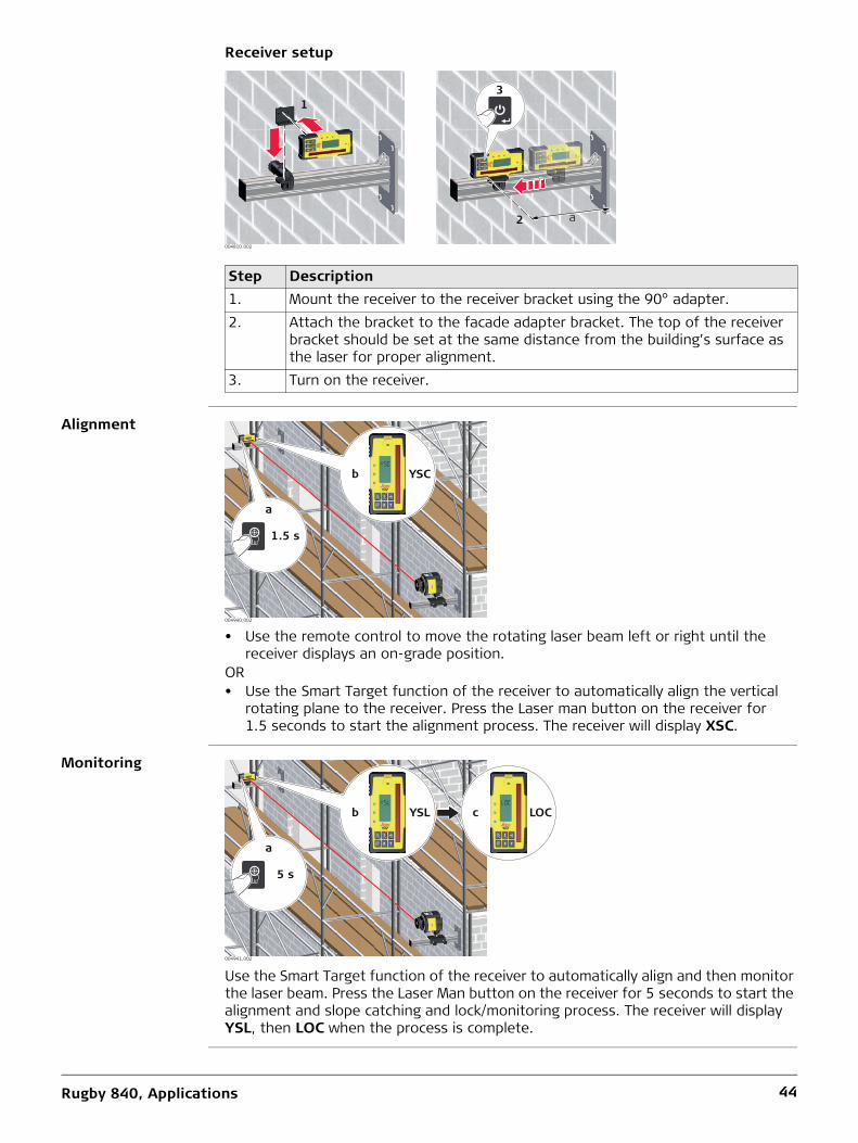
Receiver setup
Alignment
• Use the remote control to move the rotating laser beam left or right until the receiver displays an on-grade position.
OR• Use the Smart Target function of the receiver to automatically align the vertical
rotating plane to the receiver. Press the Laser man button on the receiver for 1.5 seconds to start the alignment process. The receiver will display XSC.
Monitoring
Use the Smart Target function of the receiver to automatically align and then monitor the laser beam. Press the Laser Man button on the receiver for 5 seconds to start the alignment and slope catching and lock/monitoring process. The receiver will display YSL, then LOC when the process is complete.
Step Description1. Mount the receiver to the receiver bracket using the 90° adapter.2. Attach the bracket to the facade adapter bracket. The top of the receiver
bracket should be set at the same distance from the building’s surface as the laser for proper alignment.
3. Turn on the receiver.
2 a
004810_002
13
004940_002
1.5 s
a
b YSC
5 s
8
9 YSL 10 LOC
004941_002
5 s
a
b YSL c LOC
Rugby 840, Applications 45
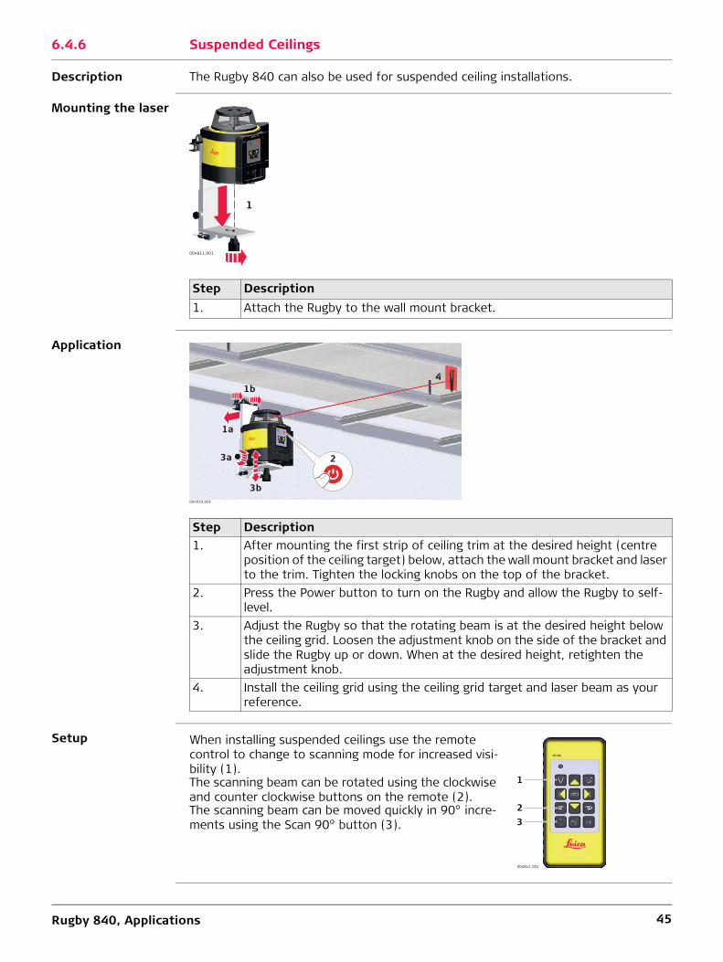
6.4.6 Suspended Ceilings
Description The Rugby 840 can also be used for suspended ceiling installations.
Mounting the laser
Application
Setup
Step Description1. Attach the Rugby to the wall mount bracket.
004811_001
1
Step Description1. After mounting the first strip of ceiling trim at the desired height (centre
position of the ceiling target) below, attach the wall mount bracket and laser to the trim. Tighten the locking knobs on the top of the bracket.
2. Press the Power button to turn on the Rugby and allow the Rugby to self-level.
3. Adjust the Rugby so that the rotating beam is at the desired height below the ceiling grid. Loosen the adjustment knob on the side of the bracket and slide the Rugby up or down. When at the desired height, retighten the adjustment knob.
4. Install the ceiling grid using the ceiling grid target and laser beam as your reference.
004939_001
2
1b
3a
1a
3b
4
When installing suspended ceilings use the remote control to change to scanning mode for increased visi-bility (1).The scanning beam can be rotated using the clockwise and counter clockwise buttons on the remote (2).The scanning beam can be moved quickly in 90° incre-ments using the Scan 90° button (3).
004812_001
1
23

Rugby 840, Applications 46
6.4.7 Layout
Description In the laying down position the Rugby 840 can be used for laying out wall positions, squaring, transferring points and more.
Layout The Rugby 840 projects two laser beams at a 90° angle to each other.
Setup
Step Description1. Place the Rugby in the laydown position.2. Press the power button to turn on the Rugby.
The Rugby will always turn on in Automatic Mode. Allow the Rugby to self-level.
3. In the laying down position the Rugby will move the beam to downwards for alignment over your reference.
4. Start the head rotation or scanning motion to roughly align the beam to a second control point.
5. Using the buttons on the laser or the remote control, fine adjust the beam until striking the second control point.
6. Once aligned the split beam and rotating beams can be used to locate 90° angles for layout. The rotating beam also creates a vertical plane for trans-ferring points from the floor to the ceiling.
004813_001
2
1
3
4
5
When using the Rugby in the laydown position use the left or right arrow buttons on your remote control to quickly align the vertical plane or plumb beam to the second reference point. (1).The scanning beam can be moved quickly to the left or right side of the laser using the Scan 90° button (2).To check the alignment over a point press the Beam down button (3).
004814_001
1
2 3
1

Rugby 840, Applications 47
More applications Exterior Applications• Setting elevation of forms and footings• Squaring of forms• Checking elevations and benchmarks• Landscaping• Drainage and septic systems• Fences and retaining walls• Decks and patios• Simple driveways or small parking lots• Facade Installations• Batter board setupsInterior Applications• Suspended ceilings• Walls and partitions• Vertical alignment• Transferring points from floor to ceiling• Vertical plumb• Layout of floors• Squaring of angles• Setting cabinets• Chair rails and wainscoting• Alignment of wall and floor tiles• Trim carpentry• Setting sprinkler head heights• Sloped ceilings
Rugby 840, Applications 48
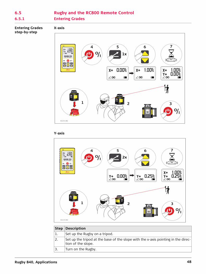
6.5 Rugby and the RC800 Remote Control6.5.1 Entering Grades
Entering Grades step-by-step
X-axis
Y-axis
Step Description1. Set up the Rugby on a tripod.2. Set up the tripod at the base of the slope with the x-axis pointing in the direc-
tion of the slope.3. Turn on the Rugby.
011171_001
64 7
IO
5
1x
1 3
IO
2
011172_001
64 7
IO
5
2x
1 2 3
IO
Rugby 840, Applications 49
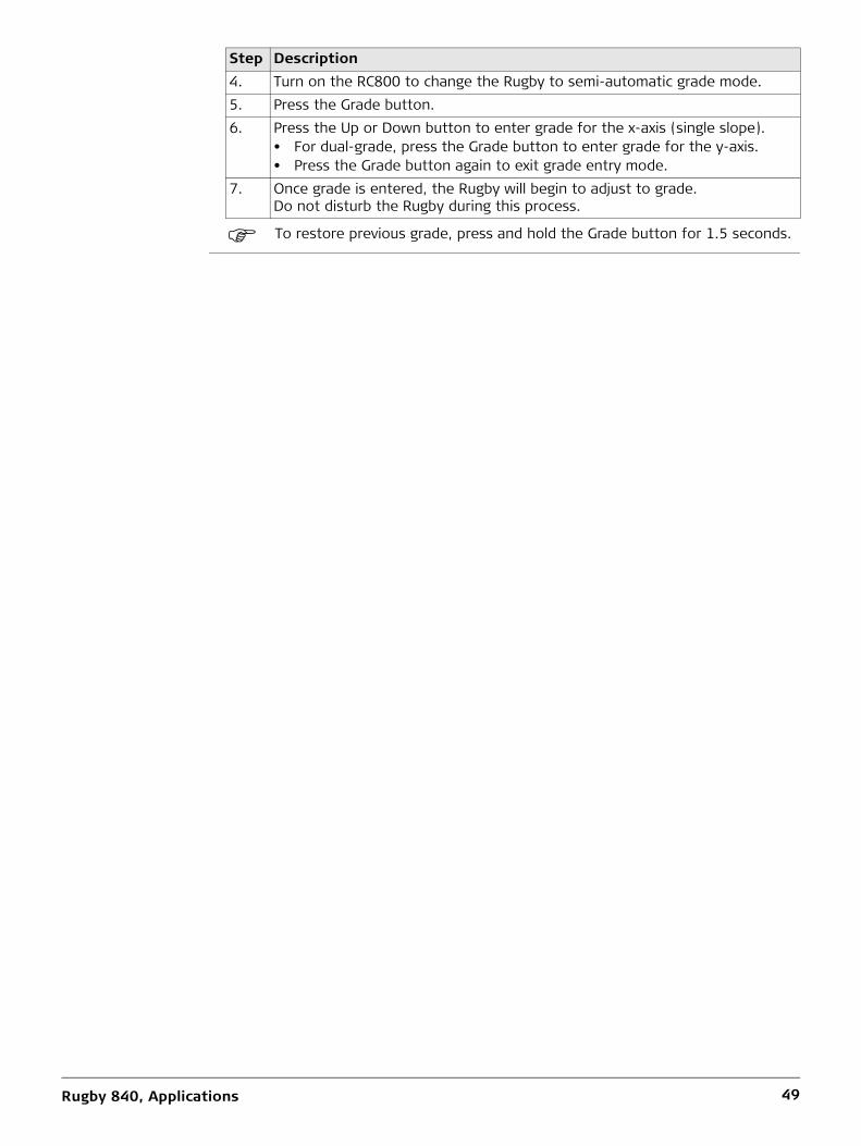
To restore previous grade, press and hold the Grade button for 1.5 seconds.
4. Turn on the RC800 to change the Rugby to semi-automatic grade mode.5. Press the Grade button.6. Press the Up or Down button to enter grade for the x-axis (single slope).
• For dual-grade, press the Grade button to enter grade for the y-axis.• Press the Grade button again to exit grade entry mode.
7. Once grade is entered, the Rugby will begin to adjust to grade. Do not disturb the Rugby during this process.
Step Description
Rugby 840, Batteries 50
7 Batteries
Description The Rugby 840 can be purchased with alkaline batteries or a rechargeable Li-Ion battery pack.The following information is appropriate only to the model you have purchased.
7.1 Operating Principles
First-time Use / Charging Batteries
• The battery must be charged prior to using it for the first time because it is deliv-ered with an energy content as low as possible.
• The permissible temperature range for charging is between 0°C to +40°C/ +32°F to +104°F. For optimal charging, we recommend charging the batteries at a low ambient temperature of +10°C to +20°C/+50°F to +68°F if possible.
• It is normal for the battery to become warm during charging. Using the chargers recommended by Leica Geosystems, it is not possible to charge the battery if the temperature is too high.
• For new batteries or batteries that have been stored for a long time (> three months), it is effectual to make only one charge/discharge cycle.
• For Li-Ion batteries, a single discharging and charging cycle is sufficient. We recom-mend carrying out the process when the battery capacity indicated on the charger or on a Leica Geosystems product deviates significantly from the actual battery capacity available.
Operation / Discharging
• The batteries can be operated from -20°C to +55°C/-4°F to +131°F.• Low operating temperatures reduce the capacity that can be drawn; high operating
temperatures reduce the service life of the battery.

Rugby 840, Batteries 51
7.2 Battery for Rugby
Charging the Li-Ion battery pack step-by-step
The rechargeable Li-Ion battery pack on the Rugby can be charged without removing the battery pack from the laser.
The battery pack reaches a full charge in approximately 5 hours if completely empty. A one hour charge should allow the Rugby to run for a full eight hours.
Step Description1. Slide the locking mechanism on the battery compartment to the very left to
expose the charge jack.2. Plug the AC connector into the appropriate AC power source.3. Connect the charger plug into the charge jack on the Rugby battery pack.4. The small LED next to the charge jack flashes indicating that the Rugby is
charging. The LED is on solid when the battery pack is fully charged.5. When the battery pack is fully charged, disconnect the charger plug from the
charge jack.6. Slide the locking mechanism to the centre position to prevent dirt from
getting into the charging jack.
4
004815_001
13
2
5
6

Rugby 840, Batteries 52
Changing the Li-Ion batteries step-by-step
The Low Battery Indicator LED on the Rugby flashes when the batteries are low and need to be charged.The charge indicator LED on the Lithium-Ion battery pack indicates when the pack is being charged (flashing slowly) or fully charged (on, not flashing).
Step Description
The batteries are inserted in the front of the laser.
The rechargeable battery pack can be recharged without being removed from the laser. Refer to " Charging the Li-Ion battery pack step-by-step" for further information.
1. Slide the locking mechanism on the battery compartment to the right and open the cover of the battery compartment.
2. To remove the batteries:Remove the batteries from the battery compartment.To insert the batteries:Insert the batteries into the battery compartment.
3. Close the cover of the battery compartment and slide the locking mecha-nism to the left centre position until it locks into position.
004816_001
1
2
3

Rugby 840, Batteries 53
Changing the alkaline batteries step-by-step
The Low Battery Indicator LED on the Rugby flashes when the batteries are low and need to replaced.
Step Description
The batteries are inserted in the front of the laser.1. Slide the locking mechanism on the battery compartment to the right and
open the cover of the battery compartment.2. To remove the batteries:
Remove the batteries from the battery compartment.To insert the batteries:Insert the batteries into the battery compartment, ensuring that the contacts are facing in the right direction.
The correct polarity is displayed on the battery holder.3. Close the cover of the battery compartment and slide the locking mecha-
nism to the left until it locks into position.
—
++
—
—+
+
004817_001
1
2
3
3

Rugby 840, Accuracy Adjustment 54
8 Accuracy Adjustment
About • It is the responsibility of the user to follow operating instructions and to periodi-cally check the accuracy of the laser and work as it progresses.
• The Rugby is adjusted to the defined accuracy specification at the factory. It is recommended to check the laser for accuracy upon receipt and periodically there-after to ensure accuracy is maintained. If the laser requires adjustment, contact your nearest authorised service centre or adjust the laser using the procedures described in this chapter.
• Only enter the accuracy adjustment mode when you plan to change the accuracy. Accuracy adjustments should only be performed by a qualified individual that understands basic adjustment principles.
• It is recommended to perform this procedure with two people on a relatively flat surface.
8.1 Checking the Level Accuracy
Checking the level accuracy step-by-step
Step Description1. Place the Rugby on a flat, level surface or tripod approximately 30 m (100 ft)
from a wall.
2. Align the first axis so that it is square to a wall. Allow the Rugby to self-level completely (approximately 1 minute after the Rugby begins to rotate).
3. Mark the position of the beam.4. Rotate the laser 180° and allow it to self-level.5. Mark the opposite side of the first axis.
6. Align the second axis of the Rugby by rotating it 90° so that this axis is square to the wall. Allow the Rugby to self-level completely.
7. Mark the position of the beam.
004825_001
30 m (100 ft)
30 m (100 ft)
X+
X—
004826_001
30 m (100 ft)
30 m (100 ft)
Y+
Y—

Rugby 840, Accuracy Adjustment 55
The Rugby is within its accuracy specification if the four marks are within ± 1.5 mm (± 1/16") from the centre.
8.2 Adjusting the Level Accuracy
Description
Entering adjust-ment mode step-by-step
The following sequence of LED behaviour occurs:• The X-axis and the Y-axis LEDs flash alternately three times.• The X-axis LED flashes three times, then flashes slowly until level. When the Rugby
is level, the X-axis LED is on, but does not flash.• The Y-axis LED is off.
Adjusting the X-axis step-by-step
The following sequence of LED behaviour occurs:• The X-axis and the Y-axis LEDs flash alternately three times.• The Y-axis LED flashes three times, then flashes slowly until level. When the Rugby
is level, the Y-axis LED is on, but does not flash.• The X-axis LED is off.
8. Rotate the laser 180° and allow it to self-level.9. Mark the opposite side of the second axis.
Step Description
In Adjustment Mode the X-axis LED indicates changes to the X-axis.
The Y-axis LED indicates changes to the Y-axis.
004827_001
X
004828_001
Y
Step Description1. Turn off the power.2. Press and hold both the Left and Right Arrow buttons.3. Press the Power button. The active axis is the X-axis.
Step Description1. Press the Left and Right Arrow buttons to increment the laser beam up and
down. Each increment is indicated by a flash of the X-axis LED and a beep from the audio indicator.
2. Continue to press the Left and Right Arrow buttons and monitor the spot until the Rugby is within its specified range.
Five steps are equal to 10 arc seconds of change, or approximately 1.5 mm at 30 m (1/16" at 100’).
3. Press the Automatic/Manual Mode button to switch to the Y-axis.

Rugby 840, Accuracy Adjustment 56
Adjusting the Y-axis step-by-step
Entering adjust-ment mode for the Z-axis step-by-step
The following sequence of LED behaviour occurs:• The X-axis and the Y-axis LEDs flash alternately three times.• The X-axis LED flashes three times, then flashes slowly until level. When the Rugby
is level, the X-axis LED is on, but does not flash.• The Y-axis LED is off.
Adjusting the Z-axis (vertical plane) step-by-step
Exiting adjustment mode step-by-step
Press and hold the Automatic/Manual Mode button for 3 seconds to save and exit Adjustment Mode.The X-axis LED and Y-axis LED flash alternately three times, then the Rugby shuts off.
Pressing the Power button at any time while in Adjustment Mode will exit the mode without saving changes.
Step Description1. Press the Left and Right Arrow buttons to increment the laser beam up and
down. Each increment is indicated by a flash of the Y-axis LED and a beep from the audio indicator.
2. Continue to press the Left and Right Arrow buttons and monitor the spot until the Rugby is within its specified range.
Five steps are equal to 10 arc seconds of change, or approximately 1.5 mm at 30 m (1/16" at 100’).
3. Press the Automatic/Manual Mode button to switch back to the X-axis if desired.
Step Description1. Turn off the power.2. Place the Rugby in the laydown position.3. With Power off, press and hold both the Left and Right Arrow buttons.4. Press the Power button. The active axis is the Z-axis.
Step Description1. Press the Left and Right Arrow buttons to increment the laser beam’s
vertical position. Each increment is indicated by a flash of the X-axis LED and a beep from the audio indicator.
2. Continue to press the Left and Right Arrow buttons and monitor the spot until the Rugby is within its specified range.

Rugby 840, Automatic Field Calibration 57
9 Automatic Field Calibration
About This procedure is unique to the Rugby lasers and uses the digital readout of the Rod Eye 180 receiver to measure, then adjust the plane of each axis. This procedure is an alternative to the traditional method described in "8 Accuracy Adjustment".
The automatic field calibration procedure cannot be used to adjust the vertical plane in the laying down position.
Description Objective: To rotate the laser to all four axes, then allow the receiver to adjust the beam automatically.
Setup
• With each rotation it may take up to 10 seconds for the calibration process to iden-tify the axis being checked, i.e. before the LED starts to blink red.
• Each step of the process is very exact and may take 1 minute to complete before the LED turns to green.
• It is important to note the colour and blink sequence to know the status of each axis in the process.
• It is not necessary to follow the steps in the exact order, but different rotation sequences will result in different LED indications.
• Increasing the distance beyond 30 meters (100 ft) between the laser and receiver will not increase the accuracy of the calibration process.
Step Description1. Pair the receiver to the laser (if not already done). Refer to "5.3 Pairing the
Rod Eye 180 with the Rugby 840" for more information.2. Mount the laser on a flat, level surface or tripod.3. Turn on the laser and align the X-axis toward the receiver position.4. Mount the receiver to a fixed position (e.g., a stationary grade rod) approx-
imately 30 meters (100 ft) from the laser.5. Turn on the receiver and position the height of the receiver near or at the
on-grade position. It is not necessary to be exact.6. Turn off the receiver.7. Turn on the receiver in CAL mode by pressing both the power and Laser man
button for five seconds.8. The display will show CAL.
9. Return to the laser and note the colour and activity of the X and Y LEDs.004749_001

Rugby 840, Automatic Field Calibration 58
Calibrating step-by-step
The following table defines and displays the LED indications that will be seen during each step of the field calibration process.
Step 1 - Rotate and align the first side of the X-axis (X+)
Step 2 - Rotate 180° and align to the opposite side of the X-axis (X-)
X-axis LED
Y-axis LED
X Y X-axis status
Y-axis status Actions
Red on Red on X-axis not aligned
Y-axis not aligned
Rotate laser until the X-axis LED is flashing red.
X-axis LED
Y-axis LED
X Y X-axis status
Y-axis status Actions
Flashing red
Off X-axis is levelling
Off Wait until the first side of the X-axis is meas-ured.
Flashing green
Red on X-axis is half complete
Y-axis not aligned
Rotate laser 180° until the X-axis LED is again flashing red.
X-axis LED
Y-axis LED
X Y X-axis status
Y-axis status Actions
Flashing red
Off X-axis is levelling
Off Wait until the reverse of the X-axis is meas-ured.
Green on Red on X-axis is complete
Y-axis not aligned
Rotate laser 90° until the Y-axis LED is flashing red.
004829 001
30 m (100 ft)X+
004830_001
30 m (100 ft)X—

Rugby 840, Automatic Field Calibration 59
Step 3 - Rotate 90° and align to the first side of the Y-axis (Y+)
Step 4 - Rotate 180° and align to the opposite side of the Y-axis (Y-)
If the calibration process was successful, the X and Y LEDs will flash alternately three times, the beeper will sound and the Rugby will then turn off.If the Rugby does not complete the procedure as noted above, the procedure has failed and must be repeated.
X-axis LED
Y-axis LED
X Y X-axis status
Y-axis status Actions
Off Flashing red
Off Y-axis is level-ling
Wait until the first side of the Y-axis is meas-ured.
Green on Flashing green
X-axis is complete
Y-axis is half complete
Rotate laser 180° until the X-axis LED is again flashing red.
X-axis LED
Y-axis LED
X Y X-axis status
Y-axis status Actions
Off Flashing red
Off Y-axis is level-ling
Wait until the reverse of the Y-axis is meas-ured.
Green on Green on X-axis is complete
Y-axis is complete
Done.
004831_001
30 m (100 ft)Y+
004832_001
30 m (100 ft)Y—

Rugby 840, Troubleshooting 60
10 Troubleshooting10.1 Rugby 840
Alerts
Troubleshooting
Alert Symptom Possible causes and solu-tions
Low Battery LED flashes red, or is on but not flashing.
The batteries are low. Replace the alkaline batteries or recharge the Li-Ion battery pack. Refer to "7 Batteries".
Elevation (H.I.) AlertThe LEDs flash quickly with an audio beep.
The Rugby has been bumped or tripod was moved. Turn off Rugby to stop alert check the height of the laser before beginning to work again. Allow Rugby to re-level and check the height of the laser.After two minutes in the alert condition, the unit will shut off automatically.
Servo Limit AlertAll LEDs flash sequentially.
The Rugby is tipped too far to reach a level position. Re-level the Rugby within the 6 degree self-levelling range.This alert will also be displayed any time the unit is tipped more than 45° from level. After two minutes in the alert condition, the unit will shut off automatically.
Temperature AlertAll LEDs are on but not flashing.
The Rugby is in an environment where it cannot operate without causing damage to the laser diode. This could be a result of heat from direct sunlight. Shade the Rugby from the sun.After two minutes in the alert condition, the unit will shut off automatically.
5 Hz +
Problem Possible Cause(s) Suggested SolutionsThe Rugby is working, but not self-levelling.
The Rugby is in Manual Mode. The Rugby must be in Auto-matic Mode to self-level. Set the Rugby to Automatic Mode by pressing the Auto-matic/Manual Mode button.– In Automatic Mode the X-
axis LED and the Y-axis LED flash green while levelling.
– In Manual Mode the X-axis LED and/or the Y-axis LED are red.

Rugby 840, Troubleshooting 61
Rugby does not turn on.
The batteries are low or dead. Check the batteries and change or charge the batteries if necessary. If the problem continues, return the Rugby to an authorised service centre for service.
The distance of the laser is reduced.
Dirt is reducing the laser output. Clean the windows of the Rugby and the receiver. If the problem continues, return the Rugby to an authorised service centre for service.
The laser receiver is not working properly.
The Rugby is not rotating. It may be levelling or in Elevation Alert.
Check for proper operation of the Rugby.
Refer to the receiver manual for more infor-mation.
The receiver is out of usable range.
Move closer to the Rugby.
The batteries of the receiver are low.
Change the receiver batteries.
The Rugby cannot communicate with the RC400 Remote Control.
The Rugby 840 and the receiver have not been paired and cannot communicate with each other.
Pair the Rugby 840 and the receiver. Refer to "2.5.1 Pairing the Rugby 840 with the RC400 Remote Control" for more information.
Elevation Alert function is not working.
The Elevation Alert function is disabled.
The Elevation Alert function is enabled or disabled by pressing the following button combination: With Rugby turned on and rotating, press and hold the Left and Right Arrow buttons. Then press the Auto-matic/Manual Mode button to enable or disable the Elevation Alert function. The Rugby beeps once to indicate the change.
The Rugby does not turn on in Automatic Mode.
The Rugby is designed to always turn on in Automatic Mode unless specifically disabled by the user.
The Automatic Mode can be enabled or disabled by pressing the Automatic/Manual Mode button.
The Rugby turns on with the last mode saved.
The Rugby is designed to always turn on in Automatic Mode unless specifically disabled by the user.
With the Rugby turned on and rotating, press the power button to turn the Rugby off. Press and hold both the Auto-matic/Manual Mode button and the power button for five seconds to enable or disable the function. The Rugby will beep once to indicate the change.
Problem Possible Cause(s) Suggested Solutions

Rugby 840, Troubleshooting 62
10.2 RC800 Remote Control
Alerts Alert Symptom Possible causes and solu-tions
Low Battery indication on the display.
The batteries are low. Replace the alkaline batteries or recharge the Li-Ion battery pack. Refer to "7 Batteries".
Elevation (H.I.) AlertThe Elevation (H.I.) Alert screen is shown and the audio beeps.(Level position)
The Rugby has been bumped or tripod was moved. Turn off Rugby to stop alert, check the height of the laser before beginning to work again. Allow Rugby to re-level and check the height of the laser.After two minutes in the alert condition, the unit will shut off automatically.
Bump AlertThe Bump Alert screen is shown and the audio beeps.(Grade position)
The Rugby has been bumped or tripod was moved. Turn off Rugby to stop alert, check the height of the laser before beginning to work again. Allow Rugby to re-level and check the height of the laser.After two minutes in the alert condition, the unit will shut off automatically.
Servo Limit AlertThe Servo Limit Alert screen is shown.
The Rugby is tipped too far to reach a level position. Re-level the Rugby within the 6 degree self-levelling range.After two minutes in the alert condition, the unit will shut off automatically.
Tilt AlertThe Tilt Alert screen is shown.
The Rugby is tipped more than 45° from level.After two minutes in the alert condition, the unit will shut off automatically.
Smart Slope AlertThe Smart Slope Alert screen is shown.
The Rugby is checking the level position before returning to grade.Refer to "Smart Slope".
011084_001
011085_001
011094_001
011095_001
011086_001

Rugby 840, Troubleshooting 63
Troubleshooting
Temperature AlertThe Temperature Alert screen is shown.
The Rugby is in an environment where it cannot operate without causing damage to the laser diode. This could be a result of heat from direct sunlight. Shade the Rugby from the sun.After two minutes in the alert condition, the unit will shut off automatically.
Function not allowed The Rugby is in Smart target, Smart lock or Calibration mode. The remote cannot be used.
Alert Symptom Possible causes and solu-tions
011096_001
011173_001
Problem Possible Cause(s) Suggested SolutionsThe Rugby is working, but not self-levelling.
The Rugby is in Grade Mode. The Rugby will self-level only when 0.00% is shown in the display. In Grade mode, the Rugby self-levels at 0.00%, then adjusts to the grade input.
Elevation (H.I.) Alert function is not working.
The Elevation (H.I.) Alert func-tion is disabled.
The Elevation (H.I.) Alert func-tion can be enabled or disabled in the Option Menu.
The Bump Alert feature activates too often.
The Bump Alert setting is too sensitive.
Change the Bump Alert setting from FINE to COARSE in the Option Menu.
The Smart Slope feature activates too often.
The Smart Slope setting is too sensitive.
Change the Smart Slope setting from FINE to COARSE in the Option Menu.
The display is too dark/light.
Contrast setting needs readjust-ment to lighting conditions.
Adjust the contrast setting in the Option Menu.
The grade shows in Percent (%) or Per mil (‰).
Wrong setting chosen. Choose the desired setting in the Option Menu.

Rugby 840, Care and Transport 64
11 Care and Transport11.1 Transport
Transport in the field
When transporting the equipment in the field, always make sure that you• either carry the product in its original transport container,• or carry the tripod with its legs splayed across your shoulder, keeping the attached
product upright.
Transport in a road vehicle
Never carry the product loose in a road vehicle, as it can be affected by shock and vibration. Always carry the product in its transport container, original packaging or equivalent and secure it.
Shipping When transporting the product by rail, air or sea, always use the complete original Leica Geosystems packaging, transport container and cardboard box, or its equivalent, to protect against shock and vibration.
Shipping, transport of batteries
When transporting or shipping batteries, the person responsible for the product must ensure that the applicable national and international rules and regulations are observed. Before transportation or shipping, contact your local passenger or freight transport company.
Field adjustment Periodically carry out test measurements and perform the field adjustments indicated in the User Manual, particularly after the product has been dropped, stored for long periods or transported.
11.2 Storage
Product Respect the temperature limits when storing the equipment, particularly in summer if the equipment is inside a vehicle. Refer to "12 Technical Data" for information about temperature limits.
Field adjustment After long periods of storage inspect the field adjustment parameters given in this user manual before using the product.
Li-Ion and alkaline batteries
For Li-Ion and alkaline batteries• Refer to "Technical Data" for information about storage temperature range.• Remove batteries from the product and the charger before storing.• After storage recharge batteries before using.• Protect batteries from damp and wetness. Wet or damp batteries must be dried
before storing or use.For Li-Ion batteries• A storage temperature range of 0°C to +30°C / +32°F to +86°F in a dry environment
is recommended to minimize self-discharging of the battery.• At the recommended storage temperature range, batteries containing a 30% to
50% charge can be stored for up to one year. After this storage period the batteries must be recharged.

Rugby 840, Care and Transport 65
11.3 Cleaning and Drying
Product and accessories
• Blow dust off lenses and prisms.• Never touch the glass with your fingers.• Use only a clean, soft, lint-free cloth for cleaning. If necessary, moisten the cloth
with water or pure alcohol. Do not use other liquids; these can attack the polymer components.
Damp products Dry the product, the transport container, the foam inserts and the accessories at a temperature not greater than 40°C /104°F and clean them. Remove the battery cover and dry the battery compartment. Do not repack until everything is completely dry. Always close the transport container when using in the field.
Cables and plugs Keep plugs clean and dry. Blow away any dirt lodged in the plugs of the connecting cables.

Rugby 840, Technical Data 66
12 Technical Data12.1 Conformity to National Regulations12.1.1 Rugby 840
Conformity to national regulations
Frequency band 2400 - 2483.5 MHz
Output power < 100 mW (e. i. r. p.)
Antenna
12.1.2 Dangerous Goods Regulations
Dangerous Goods Regulations
The products of Leica Geosystems are powered by Lithium batteries.
Lithium batteries can be dangerous under certain conditions and can pose a safety hazard. In certain conditions, Lithium batteries can overheat and ignite.
When carrying or shipping your Leica product with Lithium batteries onboard a commercial aircraft, you must do so in accordance with the IATA Dangerous Goods Regulations.
Leica Geosystems has developed Guidelines on “How to carry Leica products” and “How to ship Leica products” with Lithium batteries. Before any transpor-tation of a Leica product, we ask you to consult these guidelines on our web page (http://www.leica-geosystems.com/dgr) to ensure that you are in accord-ance with the IATA Dangerous Goods Regulations and that the Leica products can be transported correctly.
Damaged or defective batteries are prohibited from being carried or trans-ported onboard any aircraft. Therefore, ensure that the condition of any battery is safe for transportation.
• FCC Part 15 (applicable in US)• Hereby, Leica Geosystems AG, declares that the product Rugby 840 is in compliance
with the essential requirements and other relevant provisions of Directive 1999/5/EC and other applicable European Directives. The declaration of conformity may be consulted at http://www.leica-geosystems.com/ce.
Class 1 equipment according European Directive 1999/5/EC (R&TTE) can be placed on the market and be put into service without restric-tions in any EU Member state.
• The conformity for countries with other national regulations not covered by the FCC part 15 or European directive 1999/5/EC has to be approved prior to use and oper-ation.
Rugby 840: Chip antennaRod Eye 180, Digital RF Receiver: Chip antennaRC800 remote control: Chip antenna

Rugby 840, Technical Data 67
12.2 General Technical Data of the Laser
Operating range Operating range (diameter):
Self-levelling accuracy Self-levelling accuracy is defined at 25°C (77°F)
Self-levelling range
Rotation speed
Scanning modes
Laser Dimensions
Weight
Internal battery
*Operating times are dependent upon environmental conditions.
Charging the Li-Ion battery pack takes a maximum of five hours.
Use only high quality alkaline batteries to achieve operating time.
Environmental specifications
Temperature
Protection against water, dust and sand
Rugby 840: 700 m/2300 ft
Self-levelling accuracy: ±1.5 mm at 30 m (±1/16" at 100 ft)
Self-levelling range: ±6°
Rotation speed: 0, 2, 5, 10 rps
Scanning modes: 10°, 45°, 90°
004818_001
237
mm
(9.
33")
240.5 mm (9.47") 196 mm (7.72")
Rugby 840 weight with battery: 3 kg/6.6 lbs.
Type Operating times* at 20°CLithium-Ion (Li-Ion Pack) 50 hAlkaline (four D-cells) 40 h
Operating temperature Storage temperature-20°C to +50°C (-4°F to +122°F)
-40°C to +70°C(-40°F to +158°F)
ProtectionIPX8 (IEC 60529) / MIL-STD-810GDust tightProtected against continuous immersion in water.

Rugby 840, Technical Data 68
A100 Lithium-Ion charger
A800 Lithium-Ion battery pack
12.3 RC400 Remote Control
Operating range
Batteries
Remote Control Dimensions
Type: Li-Ion battery chargerInput voltage: 100 V AC-240 V AC, 50 Hz-60 HzOutput voltage: 12 V DCOutput current: 3.0 APolarity: Shaft: negative, Tip: positive
Type: Li-Ion battery packInput voltage: 12 V DCInput current: 2.5 ACharge time: 5 hours (maximum) at 20°C
Operating range (radius): 100 m / 330 ft
Batteries: Alkaline Two AA-cellsBattery life (typical usage) 70 hours
004819_001
122
mm
(4.
8")
59 mm (2.32") 25.8 mm (1.02")

Rugby 840, Technical Data 69
12.4 RC800 Remote Control
Operating range with Rugby 840
Batteries
Remote Control dimensions
Operating range (radius): 100 m / 330 ft
Batteries: Alkaline Two AA-cellsBattery life (typical usage) 70 hours
011189_001
30 mm (1.2")13
5 m
m (
5.3"
)73 mm (2.9")

Rugby 840, Warranty under PROTECT by Leica Geosystems 70
13 Warranty under PROTECT by Leica Geosystems
Description Lifetime Manufacturer’s WarrantyWarranty coverage for the entire usage time of the product under PROTECT according to Leica Geosystems International Limited Warranty and PROTECT General Terms & Conditions set out under www.leica-geosystems.com/protect. Free charge repair or replacement of all products or any parts under PROTECT that suffer defects as a result of faults in materials or manufacturing.
5 Years No CostsAdditional services should the product under PROTECT become defective and require servicing under normal conditions of use, as described in the user manual, at no addi-tional charge. To receive the “5 years no cost” period, the product must be registered at http://myworld.leica-geosystems.com within 8 weeks of the purchase date. If the product is not registered, a “Two years no cost” period applies.
Description Two Year Knockdown WarrantyIn addition to the lifetime manufacturer's warranty and the “No Cost” period for addi-tional services, the internal self-levelling system of the product under PROTECT is covered. Should any accident or knockdown occur within two years of the purchase date, all repairs to the internal self-levelling assembly will be covered under PROTECT General Terms & Conditions.
Rugby 840, Accessories 71
14 Accessories
Accessories for power supply
A100 - Li-Ion Charger (790417)The A100 Li-Ion charger comes complete with four separate AC adaptors.
A130 - 12 Volt Battery Cable (790418)The A130 12 volt battery cable connects the Rugby to a standard 12 volt automotive battery as a backup for the unit’s battery. It is only usable with the rechargeable battery pack. Length: 4 metres/13 feet.
A140 - Car Adapter Cable (797750)The A140 car adapter cable connects the Rugby to a standard automotive accessory jack as a backup for the unit’s battery or to charge in a vehicle. It is only usable with a rechargeable battery pack. Length: 2 metres/6.5 feet.
A150 - Alkaline Battery Pack (790419)The A150 alkaline battery pack is included as part of the standard alkaline package. It can also be purchased separately to be used as a backup for rechargeable models. Batteries required: Four D-cell type alkaline.
A170 - Solar Panel Kit (807479)The A170 solar panel kit runs and charges the Rugby. It is usable only with a recharge-able battery pack. The A170 solar panel comes complete with its own storage bag that can be attached directly to the Rugby carrying case.
A800 - Li-Ion Battery Pack (790416)The A800 Li-Ion battery pack is included as part of the standard rechargeable package. It can also be purchased separately as an upgrade to the alkaline battery pack. It is necessary to also purchase the A100, Li-Ion battery charger to complete the Li-Ion battery solution.
A200 - Wall Mount Bracket (790421)The A200 wall mount bracket mounts the Rugby 840 securely to the ceiling grid for suspended ceiling installations.
A210 - Ceiling Grid Target (732791)The A210 ceiling grid target attached magnetically to the ceiling grid for suspended ceilings installations.
A220 - Batter Board Clamp with Adapter (790432)The A220 batter board clamp and adapter provides the user with a simple, string free set up on batter boards. The 90° receiver adapter attaches to the main clamp for easy storage when not being used. Refer to "6.4.4 Batter Boards" for specific application information.
A280 - Facade Adapter Kit (799204)The A280 facade adapter kit provides the user with a useful setup for facade installa-tions. The kit consists of two facade adapter brackets and a batter board clamp with the 90° receiver adapter. Refer to "6.4.5 Facades" for specific application information.

Rugby 840, Accessories 72
004820_001
A800
A170
A150
A140
A130
A100
A200
A210
A280
A220

Rugby 840, Index 73
Index
AAccessories ........................................................ 71Accuracy
Self-levelling .................................................. 67Accuracy Adjustment ......................................... 54Adjust
Level Accuracy ................................................ 55Antenna
Technical Data ............................................... 66Applications
Checking Grades ............................................. 36Entering Grades ............................................. 48Manual Grades ............................................... 37Setting Forms ................................................ 35Smart Target .................................................. 38Smart Target Lock .......................................... 39
Automatic Field Calibration ................................ 57Automatic Mode ................................................ 21
BBatter Boards
Setup ............................................................. 41Batteries
Operation, Discharging ................................... 50Battery
Change alkaline batteries ............................... 53Change Li-Ion battery pack ............................. 52Charge ........................................................... 51Technical data ................................................ 67
Battery ChargerTechnical data ................................................ 68
Battery PackTechnical data ................................................ 68
Buttons ............................................................. 19
DDangerous Goods Regulations ........................... 66Definition of Use ................................................. 7Description of the system .................................. 14Digital Receiver .................................................. 33Dimensions
Of laser .......................................................... 67Of Remote Control ................................... 68, 69
Documentation .................................................... 2Dual Receiver Setups ......................................... 40
EElevation alert .................................................... 23Environmental specifications
Laser .............................................................. 67
FFacades
Setup .............................................................43FCC Statement ...................................................12Frequency Band
Rugby .............................................................66
IIndicators, LED
Level status ....................................................20Instrument
Technical Data ................................................67Turn on and off ..............................................20
Intended use ........................................................7
LLaser
Classification ..................................................10Dimensions ....................................................67
LED Indicators ....................................................20Level Accuracy
Adjust .............................................................55Check .............................................................54
Li-Ion battery .....................................................68Storage ..........................................................64
MManual mode .....................................................21Menu
Remote Control ..............................................32Rod Eye ..........................................................34
OOperating range .................................................67Output Power
Rugby .............................................................66
PPairing
Remote Control with Rugby ......................18, 25Rod Eye 180 ...................................................34
RRange
Self-levelling ...................................................67Receiver
Pairing ............................................................34Remote Control
Dimensions ..............................................68, 69Responsibilities ....................................................7

Rugby 840, Index 74
Rod EyeMenu ............................................................. 34
Rod Eye 180Buttons .......................................................... 33Instrument components ................................. 33
Rotation speed .................................................. 67
SSafety Directions ................................................. 6Scanning modes ................................................ 67Setup
Dual Receivers ............................................... 40Instrument on tripod ...................................... 16
Specifications, environmentalInstrument ..................................................... 67
TTemperature
LaserOperating ................................................. 67Storage .................................................... 67
Troubleshooting ........................................... 60, 63
UUser Manual
Validity of ........................................................ 2
WWeight
Instrument ..................................................... 67

Rugby 840, Index 75

Leica Geosystems AGHeinrich-Wild-StrasseCH-9435 HeerbruggSwitzerlandPhone +41 71 727 31 31www.leica-geosystems.com
799863-2.0.0enOriginal text Published in Switzerland © 2015 Leica Geosystems AG, Heerbrugg, Switzerland
Copyright © 2022 FDOKUMEN