Monitoring of the Curing Process of an Industrial Composite Structure by TJS and FUT
11
ARTÍCULO 27 MONITORING OF THE CURING PROCESS OF AN INDUSTRIAL COMPOSITE STRUCTURE BY TJS AND FUT M. Torres , F. Collombet , B. Douchin , L. Crouzeix , R. Bazer-Bachi , Y-H. Grunevald , J. Lubin , T. Camps , X. Jacob , S. Rodriguez , K-T. Wu . 1 2 2 2 2 3 4 4 5 5 6 1 2 3 4 5 6 INSTITUTO POLITÉCNICO NACIONAL, ESIME UNIVERSITÉ DE TOULOUSE, INSA, UPS, ICA (INSTITUT CLÉMENT ADER), COMPOSITES, EXPERTISE & SOLUTIONS UNIVERSITÉ DE TOULOUSE, LABORATORY FOR ANALYSIS AND ARCHITECTURE OF SYSTEMS UNIVERSITÉ DE TOULOUSE, LABORATORY OF HUMAN BEING PHYSICS APPLIED TO THE ENVIRONMENT INDUSTRIAL MATERIALS INSTITUTE INSTITUTO TECNOLÓGICO de saltillo SALTILLO, COAHUILA 23, 24 Y 25 DE OCTUBRE DEL 2013.
Transcript of Monitoring of the Curing Process of an Industrial Composite Structure by TJS and FUT

ARTÍCULO 27
MONITORING OF THE CURING PROCESS OF ANINDUSTRIAL COMPOSITE STRUCTURE BY TJS AND FUT
M. Torres , F. Collombet , B. Douchin , L. Crouzeix , R. Bazer-Bachi ,Y-H. Grunevald , J. Lubin , T. Camps , X. Jacob , S. Rodriguez , K-T. Wu .
1 2 2 2 2
3 4 4 5 5 6
1
2
3
4
5
6
INSTITUTO POLITÉCNICO NACIONAL, ESIMEUNIVERSITÉ DE TOULOUSE, INSA, UPS, ICA (INSTITUT CLÉMENT ADER),
COMPOSITES, EXPERTISE & SOLUTIONSUNIVERSITÉ DE TOULOUSE, LABORATORY FOR ANALYSIS AND ARCHITECTURE OF SYSTEMS
UNIVERSITÉ DE TOULOUSE, LABORATORY OF HUMAN BEING PHYSICS APPLIED TO THE ENVIRONMENTINDUSTRIAL MATERIALS INSTITUTE
INSTITUTO TECNOLÓGICOde saltillo
SALTILLO, COAHUILA 23, 24 Y 25 DE OCTUBRE DEL 2013.

MONITORING OF THE CURING PROCESS OF AN INDUSTRIAL COMPOSITE STRUCTURE BY TJS AND FUT
M. Torres*1, F. Collombet2, B. Douchin2, L. Crouzeix2, R. Bazer-Bachi2, Y-H. Grunevald3,
J. Lubin4, T. Camps4, X. Jacob5, S. Rodriguez5, K-T. Wu6.1 Instituto Politécnico Nacional, ESIME U.P. Ticomán, Av. Ticomán 600, 07340, México D.F., México
2 Université de Toulouse, INSA, UPS, ICA (Institut Clément Ader),
133 C Av. de Rangueil, F-31077 Toulouse, France.
3 Composites, Expertise & Solutions, 4 Rue Georges Vallerey, F-31320 Castanet Tolosan, France.
4 Université de Toulouse, Laboratory for Analysis and Architecture of Systems, Toulouse, France.
5 Université de Toulouse, Laboratory of Human Being Physics Applied to the Environment,
118 Route de Narbonne, 31062, Toulouse, France.
6 Industrial Materials Institute, 75 Bvld de Mortagne, Boucherville, Quebec J4B6Y4, Canada.
ABSTRACT
In this work, a multi-instrumentation setup is conceived in order to have a better
understanding of composites curing by using different devices: tunnelling junction sensor
(TJS), flexible ultrasonic transducers (FUT) and thermocouples. The sensors are
simultaneously embedded or placed on the surface of a thick carbon-epoxy plate for
monitoring its autoclave cycle. By means of their signals, the evolution of temperature related
with the polymerization state is described. A qualitative statement is provided to have a first
approach of the initial state of the composite plate in order to improve its mechanical
properties.
RESUMEN
En este trabajo, un experimento de multi-instrumentación es concebido para tener un mejor
entendimiento de la polimerización de estructuras compósitas. En él se utilizan diferentes
dispositivos: sensores a efecto túnel (TJS), transductores ultrasónicos flexibles (FUT) y
termopares (TC). Los sensores son embebidos o puestos en la superficie de una placa
carbono-epoxi para monitorear su manufactura dentro del autoclave. Mediante las señales
recuperadas, se describe la evolución de la temperatura y su relación con el estado de
polimerización del compósito. Una aproximación cualitativa es obtenida a fin de tener el
estado inicial de la placa compósita con el fin de mejorar sus propiedades mecánicas.
Keywords: curing process, carbon-epoxy plate, tunnelling junction sensor, flexible ultrasonic
transducers.
*Corresponding Author, e-mail: [email protected], Tel: (55)5729 6000 ext 56104.
1. Introduction
The nature of long-fibre composite structures allows the possibility to implement in-core
instrumentation for monitoring since the manufacturing process until their final application.
Numerous studies have proven the value added of composites in-core instrumentation to
follow through-the-thickness properties [1-4]. However, composites in-core instrumentation
still reveals worries which retard its plenty industrial application. Sensor’s size, autonomy and
wire connexions are the major issues to deal with in order to fulfil this approach in the
industry. Several researchers have shown their interest on the thermal phenomena which
occur during composites curing [3-5]. A deeper knowledge of the curing reactions will aid to
reply on many snags that appear in the fabrication stage and, in consequence, to improve
the mechanical properties of the composite structure.
This works belongs to the project called “Multi-sensor Instrumentation for the Composite
Materials and Structures (I2MC)”. It puts together the expertise of seven research teams with
the goal to study the in-core instrumentation of composites structures [7,8]. In this
collaboration, a multi-instrumentation set up is done for monitoring a composite structure
during its curing process. For instance, one of the goals is to compare the signals from
different embedded devices such as tunnelling junction sensors (TJS) [9-11], and flexible
ultrasonic transducers (FUT) [12, 13] in order to infer the curing stages of the composite
structure.
2. Experimental set up
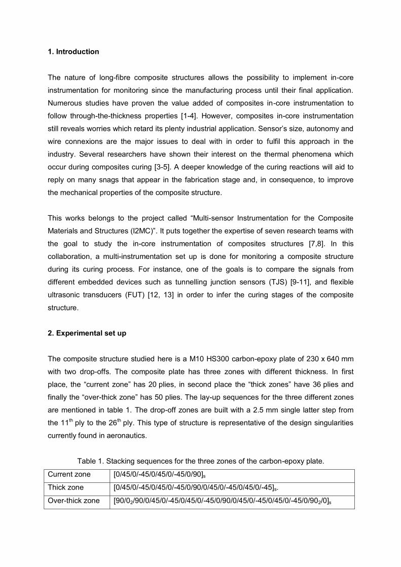
The composite structure studied here is a M10 HS300 carbon-epoxy plate of 230 x 640 mm
with two drop-offs. The composite plate has three zones with different thickness. In first
place, the “current zone” has 20 plies, in second place the “thick zones” have 36 plies and
finally the “over-thick zone” has 50 plies. The lay-up sequences for the three different zones
are mentioned in table 1. The drop-off zones are built with a 2.5 mm single latter step from
the 11th ply to the 26th ply. This type of structure is representative of the design singularities
currently found in aeronautics.
Table 1. Stacking sequences for the three zones of the carbon-epoxy plate.
Current zone [0/45/0/-45/0/45/0/-45/0/90]sThick zone [0/45/0/-45/0/45/0/-45/0/90/0/45/0/-45/0/45/0/-45]s.
Over-thick zone [90/02/90/0/45/0/-45/0/45/0/-45/0/90/0/45/0/-45/0/45/0/-45/0/902/0]s

The multi-instrumentation of the composite structure can be divided in two sets: the in-core
instrumentation and the surface instrumentation. The in-core instrumentation involves two
monitoring patches [14] with a tunnelling junction sensor (TJS) inside each one. The surface
instrumentation involves five pairs of flexible ultrasonic transducers (FUT) and nine
thermocouples (TC) at different locations of the composite plate. A general view of the
sensors arrangement on the composite plate is illustrated in figure 1. Figure 2 show some
illustrations of the experimental set-up and the placement of the plate inside the autoclave.
Picture 2-a shows the TJS being encapsulated in the monitoring patch. Picture 2-b exhibits
on of the FUT with a silicone seal. Finally, picture 2-c shows the final disposition of the plate
before its placement inside the autoclave for curing.
Figure 1. Instrumentation scheme for monitoring the curing cycle of the composite plate.
Figure 2. Illustrations of the instrumentation procedure for the composite plate.
Patch 2
TJ sensor
FUT
a)
b)
c)
TC2 TC3
TC5
TC8 TC9
TC4 TC7
Embedded thermocouple
Surface thermocouple
TC1
TC6
FUT at mould
FUT atcomposite
Large thick zoneCurrent
zoneOver-thick zone Thick zone Drop-off
mm27035 170 40 80 40
FUT 1
FUT 2
FUT 4
FUT 5
FUT 3
Monitoring patch (TJS)
Patch 2Patch 1

The polymerization cycle begins at room temperature (25ºC). Then a 2ºC/min heating slope
is provided to reach a 90ºC plateau during 45 min. After that, the temperature rises with the
same 2ºC/min slope, to have a 120ºC plateau for 2 hrs. When the second plateau ends, the
cooling phase is fixed with a -1ºC/min slope to get back at room temperature. For the
pressure, we apply 2 bar from the beginning of the cycle until the end of the first temperature
plateau. Then, the pressure is increased to 5 bar until the end of the polymerization cycle.
During all the autoclave cycle, void pressure is fixed at 0.9 bar.
3. Signal of embedded sensors: Tunnelling junction sensors (TJS)
Tunnelling junction sensors (TJS) are electronic devices which take advantage of inverse
polarization of P – N junctions, known as Symmetric Thresholds Element (STE). To stimulate
the P – N junctions, the TJS is polarized continuously. Between 100 nA and 10 mA, the
increment of energy produces the shrinkage of the potential barrier, allowing the electrons to
pass through it and the voltage increases gradually. This fact is a pure quantum physics
phenomenon, known as “tunnelling effect conduction”.
The interest on the tunnelling effect conduction lays onto its dependence to temperature
changes [9, 10]. The sensibility to temperature changes becomes evident when the
polarization current gets a value within the tunnel effect range. For a fixed polarization
current, the voltage will fluctuate as regards on the increment or decrease of temperature.
This condition makes the TJS affordable for monitoring temperature changes.
The TJS of patch 1 is connected to a SMU 2612 Keithley® power source controlled by
Labtracer software. A total of 45 TJS polarizations, from 1 nA to 10 mA, are induced during
the curing cycle in order to follow the temperature changes inside the composite plate. The
space of measurement of the TJS is detected between 2 mA and 5 mA, where the sensitivity
to temperature gets quantifiable. The voltage dependence to the temperature variation is
illustrated in figure 3.
In order to establish the link between the voltage variations of the TJS and the temperature
changes of the composite plate, a temperature – voltage – time diagram is built. Figure 4
shows the TJS voltage variations for two current values, 2.75 mA and 3.8 mA, and the
temperature measurements of the thermocouple TC5 during the curing cycle.

Figure 3. Measurement range for the tunnelling junction sensor (TJS).
On the diagram of figure 4, voltage decreases when the temperature rises and voltage
increases when temperature diminishes. The TJS voltage has an inverse relation to the
composite plate temperature. On one side, the TJS sensitivity at 2.75 mA is -8 mV/ºC; on the
other side, the TJS sensitivity at 3.8 mA is -7 mV/ºC. With these results, the trustworthiness
of using tunnelling junction sensors for composites curing monitoring is pointed.
Figure 4. Temperature – voltage – time diagram for the tunnelling junction sensor (TJS).
4
4.5
5
5.5
6
6.5
7
0
20
40
60
80
100
120
140
0 50 100 150 200 250 300 350
Volta
ge (V
)
Tem
pera
ture
(°C)
Curing cycle (min)
TC 52.75 mA
3.8 mA
2.75 mA 3.8 mA
0.0
1.0
2.0
3.0
4.0
5.0
6.0
7.0
8.0
2.0E-03 3.0E-03 4.0E-03 5.0E-03
Volta
ge (V
)
Current (A)
T 20,6°C T 24,2°C T 26,8°CT 30°C T 33,4°C T 38,5°CT 42,2°C T 43,7°C T 54,2°CT 63°C T 71,4°C T 80,1°CT 87,4°C T 91,8°C T 92,9°CT 93,5°C T 99,6°C T 115,1°CT 120,6°C T 126,6°C T 127,6°CT 106,7°C T 133,7,6°C T 126,7°CT 123,5°C T 122,6°C T 122°CT 121,7°C T 121,6°C T 121,6°CT 121,6°C T 121,6°C T 121,6°CT 120,2°C T 108,8°C T 94,9°CT 88,9°C T 84,6°C T 79,4°CT 72°C T 68,9°C T 63,5°CT 59,8°C

4. Signal of embedded sensors: Flexible Ultrasonic Transducers (FUT)
Flexible ultrasonic transducers (FUT) are one of the non-destructive techniques (NDT) which
can be used to reveal the presence of internal defects in a structure. FUT works thanks to
the piezoelectric effect of their constitutive micro-layers. By receiving an electrical
stimulation, the FUT produce a high-frequency wave that can travel through any material
which the FUT is in contact to. The parameters of the ultrasonic wave after travelling are
unique and depend only on the atomic composition and the physical state of each material.
The FUT employed on this work are composed by bismuth titanate (BIT) powders dispersed
by sol-gel spray onto a lead-zirconate-titanate (PZT) substrate of 4 mm diameter. Then, this
compound is placed onto a stainless steel foil of 12.7 mm length. This configuration, as
shown in figure 5, gives the FUT their main characteristics: flexibility, good ultrasonic
coupling and functioning at relatively high-temperature (< 500ºC). This last characteristic
makes the FUT promising for monitoring composites during curing processes.
Figure 5. Schemes of the FUT assembly and the different echoes produced by the FUT.
The amplitude and the delay of time for all echoes of each FUT are acquired. After the
polymerization process, only the echoes Lm+c and L2m can be employed for the curing
monitoring because they are strong enough. If we consider the difference between the depart
time and the return time of the echo, this “time delay” of the ultrasonic wave can be analysed
as a function of the physical state of the composite material. Time delay variations can be
attached to the chemical and physical phenomena happening inside the composite plies.
Figure 6 shows the evolution of the time delay for the duration of the curing process. There
are five recognizable phases which are described as follows. S0: phase where mould
temperature is a little above the room temperature. In this phase the resin has a lower
viscosity which provides a good coupling between the mould and the plies. The time delay
Al plate (6 mm)Teflon foil (1 mm)
Plate FUTComposite
plate
Al mould (15 mm)
Lm+cLm+3c L2m
L2m+2c
Steel rodMould FUT
Lm+cLm+3c
L2mL2m+2c
Echoes received by plate FUT
Echoes received by mould FUT

decreases and more ultrasonic waves go through the plies. S1: phase where temperature
continues rising till 90ºC. The viscosity of matrix decreases, the speed of sound diminishes
and the time delay increases until the point D1. This time delay increment is caused by a
partially melting of the resin causing an irregularly impregnation among fibres. S2: phase
corresponding to the 90ºC plateau. Theoretically, the time delay should not present any
change. However, the time delay diminishes gradually until the point D2. In this phase, it is
considered that the polymerization reaction starts. The composite morphology defined by the
mix of the solid state of the fibers and the liquid - rubbery state of the resin could be the
cause of ultrasonic fuzziness. Nonetheless, more experiments should been carried out in
order to confirm this hypothesis. S3: phase located during the second temperature slope,
from 90ºC to 120ºC. In this phase, the polymerization reaction is almost fulfilled. The
evolution of the time delay presents a point D3, probably related to the matrix gel point. After
this point, time delay decreases drastically, because of the matrix reticulation until the signal
stabilizes during the composite consolidation. S4: phase linked to the composite
consolidation. The time delay decreases steadily because of the autoclave cooling. This final
reduction is certainly related to the final composite solidification into a glassy state.
Figure 9. Evolution of the time delay in the composite plate during the curing cycle.
2
2.5
3
3.5
4
4.5
19.15
19.2
19.25
19.3
19.35
19.4
19.45
0 100 200 300 400
Tim
e del
ay in
com
posi
te (µ
s)
Tim
e del
ay o
f L2m
(µs)
Curing cycle (min)
Composite time delay
L2m
S1 S2 S3 S4
S0
D3 (Gel point)
D2
D1
Rubbery state Glassy stateLiquid state

6. Conclusions
A carbon-epoxy plate with two drop-offs is instrumented, in-core and at its surface, with
tunnelling junction sensors (TJS), flexible ultrasonic transducers (FUT), and thermocouples
(TC). This multi-instrumentation is designed to obtain information related to the
polymerization phenomena during the curing cycle.
For the tunnelling junction sensors (TJS), detection of temperature changes is confirmed and
their application in composites monitoring shows promising features. Temperature – voltage
– time diagram are built to link the temperature changes in the composite plate and the TJS
voltage changes. These sensors will get more attentions not only for their temperature
sensitivity, but for their capability for detecting strains too. The reliability of TJS for detecting
residual strains inside composites after curing cycles will be one of the key-points in the
incoming research.
An assembly of flexible ultrasonic transducers (FUT) are placed to follow the thickness
evolution of the composite plate. The measurements through-the-thickness of the ultrasonic
waves can give signs of the physical state of the composite plies. The evolution of the time
delay during the curing cycle is analysed and presents different phases. The curing phases
are identified with a unique signature beginning with the mould-composite coupling, passing
through resin reticulation and finishing with composite consolidation. With these recognizable
signatures, the viability of FUT to estimate the composite polymerization evolution is proved.
7. Acknowledgments
The present work is part of the research project “Multi-sensor Instrumentation for Composite
Materials and Structures (I2MC)” financially supported by the Thematic Advanced Research
Network for Aeronautic and Space Sciences & Technologies of Toulouse (RTRA STAE).
M. Torres conveys his special appreciation to the National Council of Science and
Technology of Mexico (CONACYT) for the financial support.
8. References
1. F. Collombet, G. Luyckx, C. Sonnenfeld, Y-H. Grunevald, Y. Davila, M. Torres, X.
Jacob, K-T. Wu, S. Rodriguez, B. Douchin, L. Crouzeix, R. Bazer-Bachi, T.
Geernaert, J. Degrieck, F. Berghmans. “Cure monitoring of an autoclave
manufactured industrial part: Added value of complementary instrumentation”.
Proceedings of the 19th International Conference on Composite Materials. 2013,
Quebec, Canada, 1178-1187.
2. C. Sonnenfeld, G. Luyckx, F. Collombet, Y-H. Grunevald, B. Douchin, L. Crouzeix, M.
Torres, T. Geernaert, S. Sulejmani, K. Chah, P. Mergo, H. Thienpont, F. Berghmans.
“Cure cycle monitoring of laminated carbon fiber-reinforced plastic with fiber Bragg
gratings in microstructured optical fiber”. Proceedings of the 19th International
Conference on Composite Materials. 2013, Quebec, Canada, 3327-3335.
3. Hernández H, Collombet F, Douchin B, Choqueuse D, Davies P, González JL. “Entire
life time monitoring of filament wound composite cylinders using Bragg grating
sensors: II. Process Monitoring”. Applied Composites Materials, 2009; 16/4: 197-209.
4. Mulle M, Zitoune R, Collombet F. “Through-the-thickness material properties
identification in a technological specimen using 3D-DIC and embedded FBG
measurements”. Experimental Mechanics, 2008; 1340-1343.
5. Mulle M, Zitoune R, Collombet F, Olivier P, Grunevald YH. “Thermal expansion of
carbon–epoxy laminates measured with embedded FBGS – Comparison with other
experimental techniques and numerical simulation”. Composites Part A, 2007; 38:
1414-1424.
6. Kim S, Murayama H, Kageyama K, Uzawa K, Kanai M. “Study on the curing process
for carbon/epoxy composites to reduce thermal residual stress”. Composites Part A:
Applied Science and Manufacturing, 2012; 43/8: 1197-1202.
7. Collombet F, Grunevald YH, Zitoune R, Mulle M. “Economical value added of Multi
Instrumented Technological Evaluators for the development of composite civil
aircraft”. Proceedings of the 16th National Journeys on Composites (JNC16),
Toulouse, France, 2009.
8. Grunevald YH. Value Added of MITE toolbox on development of a full composite
railway bogie, comparison with a classical approach. Proceedings of the 7th
International Conference on Rapid Product Development, Saint Dié des Vosges,
France, 2009.
9. Dumonteuil M. “Solution générique pour l'adressage matriciel de micro-actionneurs
thermiques et optimisation de micro-sources thermiques”. PhD Thesis (in French).
Laboratory for Analysis and Architecture of Systems (LAAS). University of Toulouse,
2007.
10. Marty B. “Conception, réalisation et mise en œuvre d’une plateforme
d’instrumentation thermique pour des applications microfluidiques”. PhD Thesis (in
French). Laboratory for Analysis and Architecture of Systems (LAAS). University of
Toulouse, 2009.
11. Lubin J. “Déploiement d'un réseau de capteurs enfouis dans des multi-plis carbone-
époxy pour l'instrumentation in-situ de structures composites pour l'avionique”. PhD
Thesis (in French). Laboratory for Analysis and Architecture of Systems (LAAS).
University of Toulouse, 2012.
12. Kobayashi M, Jen CK. “Piezoelectric thick bismuth titanate/PZT composite film
transducers for smart NDE of metals”. Smart Materials Structures 2004; 13: 951-956.
13. Kobayashi M, Jen CK, Bussiere JF, Wu KT. "High-temperature integrated and flexible
ultrasonic transducers for non-destructive testing”. NTD & E International, 2009; 42:
157-161.
14. Torres M, Crouzeix L, Collombet F, Douchin B, Grunevald Y-H. Mechanical
characterization of an alternative technique to embed sensors in composite
structures: the monitoring patch. Applied Composites Materials, 2012; 19: 379 – 391.