Manufacturing and Structural Behavior Evaluation of Composite Side Beams Using Autoclave Curing and...
8
INTERNATIONAL JOURNAL OF PRECISION ENGINEERING AND MANUFACTURING Vol. 13, No. 5, pp. 723-730 MAY 2012 / 723 DOI: 10.1007/s12541-012-0094-3 1. Introduction A reduction in the structural weight of one large component usually triggers positive synergy effects for other parts. For example, a reduction of the mass of a railway car body could leads to weight savings in the traction system, suspension, brakes and other subsystems. A reduced total weight of railway vehicles means less wear on the rails, wheels, and bearings, which would require less maintenance. 1-4 Composite materials have been used in a wide range of applications in structural design due to their superior mechanical properties over conventional materials. The bogie of a railway vehicle sustains the weight of the car body, controls the wheel sets on straight and curved track, and absorbs the vibrations. 5 The weight of the bogie makes up approximately 37% of the whole vehicle weight. Therefore, reducing the weight of the components making up the bogie system is essential for a lightweight design of a railway vehicle. In particular, a bogie frame, which accounts for approximately 20% of the bogie weight, is intended to support heavy static and dynamic loads, such as the vertical load by the body of the vehicle, braking and accelerating load, twisting load induced by track twisting, and traction load. This is why it is commonplace to produce the bogie frame with steel plate (especially a freight bogie) or welded structures. Such bogie frames are heavy, ranging from 1 ton to 2 tons, and rigid and have to be equipped with suspension and damping systems in order to safeguard the comfort of the passengers of the vehicle and absorb vibrations due to the irregularities of the railway track on which the vehicle runs. There have been few attempts to develop the bogie frame using composite materials. Geuenich and Leo, et al. 6-8 built the world’s first bogie frame made of glass fiber reinforced plastics (GFRP). They targeted the bogie frame of a passenger train. The use of composite elements for the frame of the bogies gave a weight reduction of approximately 25%, enabling minimization of power capacity, energy consumption, and wear. Maurin et al. 9 assessed the mechanical reliability of the side beam of a composite-based bogie frame using a FBG sensor. They noted that the ultimate load of the composite side beam before the first failure appeared to be greater than 350 kN. The objective of the present work is to design, analyze, fabricate and testing of a GFRP side beam. The composite side beam was manufactured using two different method; autoclave curing method and resin transfer moulding method (RTM). It is targeted to replace a welded steel side beam for urban subway trains with the corresponding composite beam. Because of high elastic Manufacturing and Structural Behavior Evaluation of Composite Side Beams Using Autoclave Curing and Resin Transfer Moulding Method Jung-Seok Kim 1,# and Woo-Geun Lee 2 1 Railroad Structural Research Department, Korea Railroad Research Institute, 374-1, Woulam-dong, Uiwang-si, Gyeonggi-do, Korea, 437-050 2 Railway System Engineering, University of Science & Technology, 176 Gajeong-dong, Yuseong-gu, Deajeon, Korea, 305-350 # Corresponding Author / E-mail: j[email protected], TEL: +82-31-460-5663, FAX: +82-31-460-5289 KEYWORDS: Composite bogie, Bogie frame, Side beam, Subway In this study, in order to replace the conventional steel bogie with a composite bogie, a composite side beam made of glass/epoxy was developed to be used in the bogie frame of an urban subway train. The composite side beam was manufactured using two different manufacturing method; autoclave curing method and resin transfer moulding method (RTM). And, then, they were tested under a vertical load of 140 kN to evaluate the structural behavior. Moreover, the stress and strain distribution was evaluated with the finite element method and compared with the experiment. The maximum deflections of the two side beam were 7.74 mm and 8.25 mm, respectively. The side beam made by RTM appeared a little softer than the autoclave cured one due to the lower fiber volume fraction. Through the parametric study for the different design parameters, it was known that the variation of the side beam height appeared to be strongest effect to deflection. Manuscript received: March 15, 2011 / Accepted: December 8, 2011 © KSPE and Springer 2012
Transcript of Manufacturing and Structural Behavior Evaluation of Composite Side Beams Using Autoclave Curing and...

INTERNATIONAL JOURNAL OF PRECISION ENGINEERING AND MANUFACTURING Vol. 13, No. 5, pp. 723-730 MAY 2012 / 723 DOI: 10.1007/s12541-012-0094-3
1. Introduction
A reduction in the structural weight of one large component usually triggers positive synergy effects for other parts. For example, a reduction of the mass of a railway car body could leads to weight savings in the traction system, suspension, brakes and other subsystems. A reduced total weight of railway vehicles means less wear on the rails, wheels, and bearings, which would require less maintenance.1-4 Composite materials have been used in a wide range of applications in structural design due to their superior mechanical properties over conventional materials. The bogie of a railway vehicle sustains the weight of the car body, controls the wheel sets on straight and curved track, and absorbs the vibrations.5 The weight of the bogie makes up approximately 37% of the whole vehicle weight. Therefore, reducing the weight of the components making up the bogie system is essential for a lightweight design of a railway vehicle. In particular, a bogie frame, which accounts for approximately 20% of the bogie weight, is intended to support heavy static and dynamic loads, such as the vertical load by the body of the vehicle, braking and accelerating load, twisting load induced by track twisting, and traction load. This is why it is commonplace to produce the bogie frame with steel plate
(especially a freight bogie) or welded structures. Such bogie frames are heavy, ranging from 1 ton to 2 tons, and rigid and have to be equipped with suspension and damping systems in order to safeguard the comfort of the passengers of the vehicle and absorb vibrations due to the irregularities of the railway track on which the vehicle runs. There have been few attempts to develop the bogie frame using composite materials. Geuenich and Leo, et al.6-8 built the world’s first bogie frame made of glass fiber reinforced plastics (GFRP). They targeted the bogie frame of a passenger train. The use of composite elements for the frame of the bogies gave a weight reduction of approximately 25%, enabling minimization of power capacity, energy consumption, and wear. Maurin et al.9 assessed the mechanical reliability of the side beam of a composite-based bogie frame using a FBG sensor. They noted that the ultimate load of the composite side beam before the first failure appeared to be greater than 350 kN.
The objective of the present work is to design, analyze, fabricate and testing of a GFRP side beam. The composite side beam was manufactured using two different method; autoclave curing method and resin transfer moulding method (RTM). It is targeted to replace a welded steel side beam for urban subway trains with the corresponding composite beam. Because of high elastic
Manufacturing and Structural Behavior Evaluation of Composite Side Beams Using Autoclave Curing and Resin Transfer Moulding Method
Jung-Seok Kim1,# and Woo-Geun Lee2 1 Railroad Structural Research Department, Korea Railroad Research Institute, 374-1, Woulam-dong, Uiwang-si, Gyeonggi-do, Korea, 437-050
2 Railway System Engineering, University of Science & Technology, 176 Gajeong-dong, Yuseong-gu, Deajeon, Korea, 305-350 # Corresponding Author / E-mail: [email protected], TEL: +82-31-460-5663, FAX: +82-31-460-5289
KEYWORDS: Composite bogie, Bogie frame, Side beam, Subway
In this study, in order to replace the conventional steel bogie with a composite bogie, a composite side beam made of glass/epoxy was developed to be used in the bogie frame of an urban subway train. The composite side beam was manufactured using two different manufacturing method; autoclave curing method and resin transfer moulding method (RTM). And, then, they were tested under a vertical load of 140 kN to evaluate the structural behavior. Moreover, the stress and strain distribution was evaluated with the finite element method and compared with the experiment. The maximum deflections of the two side beam were 7.74 mm and 8.25 mm, respectively. The side beam made by RTM appeared a little softer than the autoclave cured one due to the lower fiber volume fraction. Through the parametric study for the different design parameters, it was known that the variation of the side beam height appeared to be strongest effect to deflection.
Manuscript received: March 15, 2011 / Accepted: December 8, 2011
© KSPE and Springer 2012

724 / MAY 2012 INTERNATIONAL JOURNAL OF PRECISION ENGINEERING AND MANUFACTURING Vol. 13, No. 5 strain energy storage capacity and high strength-to-weight ratio compared with those of steel, the GFRP has been used as suspension leaf springs in automobiles and railways.10-12 Based on these good characteristics of the GFRP, in this study, the possibility of a multi-functional GFRP side beam, which not only sustains heavy static and dynamic loads but also has the function of suspension, was investigated.
2. Configuration of the side beam
2.1 Steel side beam Usually, the bogie of urban subway trains is subjected to more
load variation than the passenger trains due to the passenger weight difference between the full weight condition during rush hour and the tare weight condition. The passenger weight difference of the urban subway train is in the range of 25 tons to 30 tons, while in case of the passenger train, it ranges from 6 tons to 10 tons. The conventional steel side beam of the urban subway train is manufactured as a welded steel box format (like a hollow tube) to reduce the weight (Fig. 1(a)). It is 2970 mm long, 200 mm wide, and 145 mm high. The top and bottom cover plates have thickness of 10 mm and 15 mm. The thickness of the inside plates is ranging from 10 mm to 12 mm, and the vertical rib plates is 9 mm thick. The SM490A steel is usually used as the base material of the side beam. The yield strength and the tensile strength of the SM490A steel are 330 MPa and 500 MPa, respectively.
2.2 Composite side beam
In this study, the composite side beam was designed based on the conventional one. Therefore, its dimension is 2970 mm long, 200 mm wide, and 150 mm high. In order to meet the structural requirements, it was composed of four components; skin, composite chords, ribs, and foam cores (Fig. 1(b)). The ribs sustain the bending induced by the vehicle weight and the composite chords support the lateral deformation of the ribs and skin. The foam cores fill the empty space among the ribs and the skin also sustains the bending and assembles tightly the above components. The skin is 15 mm thick and the rib is 10 mm thick. And, the foam core is 30 mm thick.
3. Comparison of the structural behavior of the side beams using FEM
Before the design and manufacturing of the composite side
beam, in this study, the structural behaviors such as maximum deflection and maximum stress were evaluated in order to verify the possibility of the composite material to apply the side beam for the bogie frame using finite element analysis. In order to achieve this goal, the side beam with three different materials such as steel, carbon/epoxy, and glass/epoxy were modeled and analyzed. In each composite side beam, the layup of the skin was [0]56T and the rib had two different layup of [0]44T and [0/±45/90]11T.
top plate
bottom plate
side platerib
x
y
z
145mm
(a)
150mm
: skin
: composite chord
: Rib
: Foam core
(b)
Fig. 1 Schematic drawing of the steel (a) and composite side beams (b)
Table 1 Weight information of the urban subway train used
Symbols Meaning Values Wtare Tare weight 33.8 tones Wp Maximum passenger weight 29.0 tones
Wunsprung Unsprung weight 6.56 tones
3.1 Loading conditions The weight conditions of the urban subway train are listed in
Table 1. From the weight data, the vertical load imposed on single composite side beam was calculated using Eq. (1).
Fv= (Wtare+Wp-Wunsprung)/4 (1)
where Wtare is the tare weight, Wp is the maximum passenger weight, Wunsprung is the unsprung weight of the train.
The vertical force calculated from Eq. (1) and data of Table 1 was 140 kN.
3.2 Finite element modeling
The steel side beam was modeled using S4 shell elements. In the composite side beam, the skin was modeled using S4 layered shell elements, and the shell elements were meshed on the middle surface of the skin, which had a thickness of 15 mm. The composite core and rib was modeled with SC8R continuum shell elements. Finally, the foam core was modeled using C3D8I solid elements. The layup structure definition, such as fiber orientation, ply thickness, local coordinate definition, and number of integration points through the ply thickness, of the three composite parts, except the foam core, was completed using the composite layup module supplied by ABAQUS.13 The shell elements of the skin part were connected with the inner parts meshed by the solid and continuum shell elements using tie constraints.
INTERNATIONAL JOURNAL OF PRECISION ENGINEERING AND MANUFACTURING Vol. 13, No. 5 MAY 2012 / 725
Fixed region Deformable region Fixed region1285mm842.5mm 842.5mm
Supporting point
Supporting point
Uy=Uz=0φx=φy=0
Ux=Uy=Uz=0φx=φy=0
x
y
(a)
Deformable regionFixedregion
Fixedregion
290mm2390mm
290mmSupporting
point Supporting point
Uy=Uz=0φx=φy=0
Ux=Uy=Uz=0φx=φy=0
x
y
(b)
Fig. 2 Boundary conditions of the side beams
Table 2 Material properties of composite materials used
* Refer to the manufacturer’s sheets
In Table 2, E11 and E22 mean the elastic modulus in direction of
warp and fill. G12, G13 and G23 are the in plane and the out-of plane shear modulus. X and Y are the strength in direction of warp and fill. S is shear strength. Subscript t and c mean the tensile and compressive properties. ν is Poisson’s ratio.
The boundary conditions are shown in the Fig. 2. There are two supporting points at each side beam model. These are locations of the wheel rotation center. The right supporting points were allowed to rotate only about the z-axis, Ux=Uy=Uz=φx=φy=0. In contrast, the translation along the longitudinal direction and the rotation about the z-axis was possible at the left supporting points (Uy=Uz=φx=φy=0). The supporting points were connected with the composite side beam by means of the MPC constraints. The vertical load was imposed on the top surface of the side beam by pressure. In this analysis, the boundary condition of Fig. 2(a) was used. Table 2 lists the material properties of the carbon/epoxy and glass/epoxy used in this study.
3.3 Analysis results
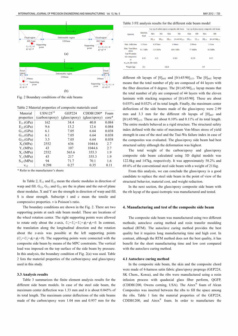
Table 3 summarizes the finite element analysis results for the different side beam models. In case of the steel side beam, the maximum center deflection was 1.33 mm and it is about 0.045% of its total length. The maximum center deflections of the side beams made of the carbon/epoxy were 1.04 mm and 0.957 mm for the
different rib layups of [0]44T and [0/±45/90]11T. The [0]44T layup means that the total number of ply are composed of 44 layers with the fiber direction of 0 degree. The [0/±45/90]11T layup means that the total number of ply are composed of 44 layers with the eleven laminate with stacking sequence of [0/±45/90]. These are about 0.035% and 0.032% of its total length. Finally, the maximum center deflections of the side beams made of the glass/epoxy were 2.99 mm and 3.3 mm for the different rib layups of [0]44T and [0/±45/90]11T. These are about 0.10% and 0.11% of its total length. The entire models behaved as a rigid structure. The structural safety index defined with the ratio of maximum Von-Mises stress of yield strength in case of the steel and the Tsai-Wu failure index in case of the composites was evaluated. The glass/epoxy side beam had best structural safety although the deformation was highest.
The total weight of the carbon/epoxy and glass/epoxy composite side beam calculated using 3D digital models was 122.8kg and 147kg, respectively. It was approximately 58.2% and 69.6% of the conventional steel side beam with a weight of 211kg.
From this analysis, we can conclude the glass/epoxy is a good candidate to replace the steel side beam in the point of view of the structural behavior, material cost, and weight reduction.
In the next section, the glass/epoxy composite side beam with the rib layup of the quasi-isotropic was manufactured and tested.
4. Manufacturing and test of the composite side beam The composite side beam was manufactured using two different
methods; autoclave curing method and resin transfer moulding method (RTM). The autoclave curing method provides the best quality but it requires long manufacturing time and high cost. In contrast, although the RTM method does not the best quality, it has benefit for the short manufacturing time and low cost compared with the autoclave curing method.
4.1 Autoclave curing method
In the composite side beam, the skin and the composite chord were made of 4-harness satin fabric glass/epoxy prepregs (GEP224, SK Chem., Korea), and the ribs were manufactured using a resin infusion process with quadaxial glass fiber perform, QGFP, (CDDB1200, Owens corning, USA). The Airex® foam of Alcan Composites was inserted between the ribs to fill the space among the ribs. Table 1 lists the material properties of the GEP224, CDDB1200, and Airex® foam. In order to manufacture the
Material properties
USN12514 (carbon/epoxy)
GEP224 (glass/epoxy)
CDDB1200*(glass/epoxy)
Foamcore*
E11 (GPa) 162 34.4 40.0 0.084E22 (GPa) 9.6 13.2 12.6 0.084G12 (GPa) 6.1 7.05 6.64 0.038G13 (GPa) 6.1 7.05 6.64 0.038G23 (GPa) 3.5 7.05 6.64 0.038Xt (MPa) 2552 636 1044.6 2.7Yt (MPa) 43 107 1044.6 2.7Xc (MPa) 2552 565.6 355.3 1.9Yc (MPa) 43 217 355.3 1.9S12 (MPa) 94 71.7 70.1 1.6
ν12 0.298 0.27 0.35 0.11
Table 3 FE analysis results for the different side beam model

726 / MAY 2012 INTERNATIONAL JOURNAL OF PRECISION ENGINEERING AND MANUFACTURING Vol. 13, No. 5
composite side beam, first, the plates for ribs were manufactured using the resin infusion process.
For this process, eleven QGFP sheets with a thickness of 0.91mm were laid up. The QGFP sheet was composed of four layers of 0o, 90o, 45o and -45o unidirectional glass fiber. After the completion of the layup, the resin, which had a mixing ratio of the epoxy resin to the hardener of 100:33 (KukDo Chem., Korea), was infused into the stacked QGFP sheets by vacuum. After completion of the resin infusion, the plate was cured in an oven for 2 hours at 80oC, and finally, the plate for ribs was completed. The cured plate was cut using a diamond cutting machine and bonded with the foam cores, which were already trimmed, using FM73 adhesive film (Cytec, USA) (Fig. 3(a)-(b)).
The bonded parts were vacuum-packed and then cured in the oven for one and half hours at 80oC. In order to make the composite chord, the GEP224 prepregs were laid up between the ribs on the top and bottom of the foam core to the required thickness (Fig. 3(c)). The composite chord increases the bending stiffness and sustains the compressive force imposed on the width direction. After the completion of the layup, the part was vacuum-packed (Fig. 3(d)) and then cured in the oven. After the manufacturing of the inner structural part (Fig. 4(a)), the fifty six GEP224 prepregs were laid
up on its surface to form the skin (Fig. 4(b)). The totally stacked composite beam was cured in the autoclave (Fig. 4(c)) under curing cycle of Fig. 5. Fig. 4(d) is the picture of the final product and it weighed 145kg. The fiber volume fraction of the fully cured skin and rib was 60% and 50%, respectively.
4.2 Resin transfer moulding method
The manufacturing process of the composite side beam using the resin transfer moulding is the same as the process using the autoclave curing method with the exception of the skin manufacturing process. The uni-axial glass fiber perform (Owens corning, USA) was stacked on the inner structure surfaces prepared in advance (Fig. 6(a)).
Fig. 6(b) presents the three different elements of the RTM mould. All elements of the mould were made of GFRP and the mould has six injection holes. In order to improve the resin flowing, glass mesh sheets were placed on the inside surfaces of the GFRP moulds. In the RTM process, low-temperature curing epoxy resin, RIM135 (Momentive Specialty Chemicals Inc., USA) and hardener were used to impregnate the fibres. The RTM pump pressure needed to inject the resin varied from 1.5 bar at the beginning to 3.0 bar at the end of the RTM process. After 15 min the preform was wetted. However, in order to ensure a complete impregnation of the fibres in the preform, the resin injection was continued for 60 min
(a) (b)
(c) (d)
(b)
Fig. 3 Manufacturing process for the inner structural parts
(a) (b)
(c) (d)
Fig. 4 Skin layup and curing process of the composite side beam
Time
Time
125
1.0
6080
6.0
180 min
60 min1.5 ºC/min
2.5 ºC/min
Pressure Release Point
Pressure in Autoclave
Vaccum bagging Pressure
Open the Autoclave
Fig. 5 Curing cycle of the composite side beams
(a) (b)
(c) (d)
Fig. 6 Manufacturing process of the side beam using RTM

INTERNATIONAL JOURNAL OF PRECISION ENGINEERING AND MANUFACTURING Vol. 13, No. 5 MAY 2012 / 727
(Fig. 6(c)-(d)). After the injection, it was cured in the oven under temperature of 50oC for 4hours. Fig. 7(a)-(c) describes the demoulding process of the composite side beam. The weight of the final product (Fig. 7(d)) was 148.5kg. The fibre volume fraction of 55% was achieved with a good laminate quality.
4.3 Test setup
The objective of the composite side beam is not only to reduce the weight but also to use the high specific strain energy capacity of the composite materials over the steel. Usually, GFRP (glass fiber reinforced plastics) presents advantages over carbon/epoxy such as lower sensitivity to cracks, impact and wear damage, low cost and high failure strain. In order to evaluate the allowable deflection under the same load condition as the steel side beam, in this study, the supporting points were moved outward from the center compared with the conventional supporting condition as shown in Fig. 2(b). Through the comparison of Fig. 2(a) and (b), the deformable region in the boundary condition of Fig. 2(b) was 86% wider than Fig. 2(a).
In order to conduct the test for the composite side beams, two types of supporting jig were designed and fabricated to realize the boundary condition of Fig. 2. The purpose of the jigs was to sustain the vertical load and allow the longitudinal and rotational displacements. The right side jig illustrated in Fig. 8(a) supports the vertical load and allows only rotation around the z axis. The left side jig of Fig. 8(a), on other hand, supports the vertical load and allows both the translation along the longitudinal direction of the composite side beam (x-direction) and the rotation around the z axis. The composite side beam was installed on both jigs by means of the upper plate and the lower plate using four bolts.
Fig. 8(b)-(c) shows the test setup of the two types of side beam. For the test, the vertical load using a 500 kN capacity hydraulic loading machine (MTS, USA) was applied at the center of the side beam. The center deflection of the side beam was measured using a LVDT, which was located in the bottom of the side beam. In order to measure the strain distribution on the skin of the composite side beam, four strain gauges (TML, Japan) were bonded on the surface of the side beam.
L=2970mm
Vertical load
LVDT
Composite side beam
Strain gauge
x
y
Supporting jig
(a)
(b) (c)
Fig. 8 Boundary conditions of the side beams
0 2 4 6 8 100
20
40
60
80
100
120
140
160
Side beam manufactured by autoclave curing Side beam manufactured by RTM
Ver
tical
load
(kN
)
Center deflection (mm)
Kauto
KRTM
Fig. 9 Boundary conditions of the side beams
5. Results and discussions
5.1 Test results Fig. 9 shows the load–center deflection curves of the side beam
manufactured by the autoclave curing method and RTM. The maximum deflections of the two side beams were 7.74 mm and 8.25 mm, respectively. Based on the deflections of the two models, the stiffness values of each side beam were 17.7 kN/m for the autoclave cured side beam and 16.6 kN/m for the side beam made by RTM. The side beam made by RTM appeared a little softer than the autoclave cured one due to the lower fiber volume fraction.
The load–center deflection curves presented nearly linear elastic behavior; however, it had a little hysteresis. There could be several reasons for the hysteresis behavior. One of the main reasons would be the friction between the side beam and the fixing plates (upper
(a) (b)
(c) (d)
Fig. 7 Demoulding process of the composite side beam

728 / MAY 2012 INTERNATIONAL JOURNAL OF PRECISION ENGINEERING AND MANUFACTURING Vol. 13, No. 5
plate and lower plate). In this test, the composite side beam was installed between the two steel fixing plates that were fastened using four bolts (see Fig. 8). Although the bolts were fastened tightly, there might be a little slip between the side beam and the fixing plates.
In the present side beam, there are four inflection points where the height of the side beam changes, points ①, ②, ③ and ④. At the points ① and ④, the height of it starts to extend linearly and, at the points ② and ③, the height of it keeps a constant value. The ε11 strain values measured from the two side beams were listed in Table 4. In the both models, the maximum strain occurred at the point ④ near the right side jig that allows only rotation around the z axis. The maximum of the measured strain was 0.122% and 0.126%. These values were 6.23% and 6.43% of the failure strain of the GEP224.
In addition, the longitudinal strain (ε11) distribution along the bottom line of the composite side beam was plotted in the Fig. 10. From the numerical results, the strain values were drastically increased or decreased near the inflection points. The maximum strain occurred at the x/L=0.17 and 0.83 position where the height starts to extend linearly from the boundary points. The strain abruptly decreased at the x/L=0.4 and 0.6 position where the height started to become a constant value. The calculated maximum strain was 0.134%.
5.2 Stress distribution in the composite side beam
In order to evaluate the detail stress distribution of the whole side beam, the finite element analysis was carried out for the autoclave cured side beam and the results were compared with the measured one. The same finite element model and loading condition used in Section 3 was used, while the boundary condition
was changed from Fig. 2(a) to Fig. 2(b). The calculated center deflection was 7.95 mm and it was coincident with an error of 3.6% compared with the measured one.
The maximum Tsai-Wu failure indexes of the skin and the composite chord were 0.130 and 0.096 (Fig. 11). The maximum values occurred at the inflection point ① of the lower surface of the skin and on the inclined sections of the lower chord by bending of the beam. However, the ribs showed a little different behavior. As the vertical load was imposed on the center of the beam, its upper center area was expended outward and, inversely, the lower center area was deformed inward as seen in Fig. 12. On the other hand, in case of the outermost rib placed at the boundary area, it was severely deformed inward in the lower part, and the top and the bottom parts were supported by the composite chord. The maximum Tsai-Wu failure indexes appeared in the upper part of the outermost rib adjacent to the supporting composite chord as shown in Fig. 12. As the rib thickness and the vertical load were given, the magnitude of the deformation of the ribs might depend on the stiffness of the foam core, which bonded between the ribs. Fig. 13 presents the Goodman diagram of the composite side beam
Table 4 The ε11 strain values measured from the two side beams
No. of strain gages Manufacturing methods Autoclave curing RTM
1 0.108% 0.113% 2 0.095% 0.103% 3 0.095% 0.096% 4 0.122% 0.126%
0.0 0.2 0.4 0.6 0.8 1.0-0.02
0.00
0.02
0.04
0.06
0.08
0.10
0.12
0.14
0.16
FE resutls Experiment (autoclave cured) Experiment (RTM)
Stra
in, ε
11 (%
)
x/L
Fig. 10 The longitudinal strain (ε11) distribution along the bottom line of the composite side beam
Max. Tsai-Wu index
Max. Tsai-Wu index
(a)
(b)
Fig. 11 Tsai-Wu failure indexes of the skin (a) and the composite chord (b)
center
outermost rib
Composite chord
0.077mm
0.054mm
Max. Tsai-Wu index
A
A
X-directional deformation along A-A section
Tsai-Wu index contour and deformed shape
Fig. 12 The Tsai-Wu failure index distribution for the ribs

INTERNATIONAL JOURNAL OF PRECISION ENGINEERING AND MANUFACTURING Vol. 13, No. 5 MAY 2012 / 729
-600 -400 -200 0 200 400 6000
20
40
60
80
100
120
140
Stress amplitude(MPa)
Mean stress(MPa)
Endurance limit for warp direction Endurance limit for warp/fill laminate
No 1 strain gauge No 2 strain gauge No 3 strain gauge No 4 strain gauge
Fig. 13 Goodman diagram for the composite side beam manufactured by the autoclave curing method
manufactured by the autoclave curing method under the vertical and dynamic loads. The vertical load is induced by the carbody weight, while the dynamic load, which takes into account the dynamic effect acting on the carbody, is corresponding to 1.3 times of the vertical load. In the Fig. 13, there are two endurance limits: warp direction and warp/fill laminate. As known from the Fig. 13, the stress values are within the endurance limits and it means that the side beam satisfies the structural safety. 5.3 Parametric study
The composite side beam proposed in this study must not only support the vertical load but also act as a suspension in the bogie system. Therefore, the allowable deflection was investigated according to the different design parameters as follows;
height of the side beam (mm): 90,100,110,120,130, 140,150 thickness of rib (mm): 4, 6, 7.5, 9, and 10 layup of the skin: [0/θ/-θ/0]11T, θ={0o, 30o, 45o, 60o, 90o}
In this, the center deflection of the side beam according to the
variation of these parameters selected was investigated because the parameters determine the stiffness of composite side beam.
Fig. 14(a) plots the height of the side beam vs the center deflection curve. Fig. 14(a) reveals that the center deflection exponentially increased according to the decrease of the height of the side beam. The center deflection of the side beam height of 90 mm was 18.2 mm and it was about 2.26 times high over the model of the side beam height of 150 mm. Fig. 14(b) plots the rib thickness vs the center deflection curve. The center deflection linearly increased according to the decrease of the rib thickness. The center deflection at the rib thickness of 4 mm was 8.94 mm and it was about 11.2% higher than the reference model.
Fig. 15 plots the stacking sequence of the skin vs the center deflection curve. The center deflection increased according to the fiber orientation angle. The center deflection of the model, which has the skin stacking sequence of [0/90/90/0]11T was 9.57 mm and it was about 19.0% higher than the reference model that has the skin
stacking sequence of [0/0/0/0]11T.
6. Conclusions In this study, in order to replace the conventional steel bogie
with a composite bogie, a composite side beam made of glass/epoxy was designed and manufactured to be used in the bogie frame of an urban subway train. Although the side beam
80 90 100 110 120 130 140 150 1600
5
10
15
20
Cen
ter d
efle
ctio
n (m
m)
Heigth of side frame (mm)
(a)
(b)
0 2 4 6 8 10 125
6
7
8
9
10
Cen
ter d
efle
ctio
n (m
m)
Thickness of rib (mm)
Fig. 14 Center deflection according to different height of the side beam (a) and rib thickness (b)
0 20 40 60 80 1005
6
7
8
9
10
Cen
ter d
efle
ctio
n (m
m)
[0/θ/−θ/0]
Fig. 15 Center deflection according to different layup of the skin

730 / MAY 2012 INTERNATIONAL JOURNAL OF PRECISION ENGINEERING AND MANUFACTURING Vol. 13, No. 5 manufactured by the autoclave curing method had better structural properties, the side beam manufactured by the RTM revealed the good structural properties and a little higher deflection. The strain distribution along the longitudinal direction showed three peaks and two valleys due to the variation of the cross sectional area of the composite side beam.
Through the parametric study for the different design parameters; height of the composite side beam, thickness of rib and stacking sequence of the skin, the variation of the side beam height showed strongest effect to deflection. In contrast, the variation of the rib thickness showed weakest effect to deflection.
The evaluation of fatigue strength using the Goodman diagram showed that the side beam met the structural safety.
The results of this study can be used as the basic data to develop the whole composite bogie frame. Especially, the investigation for the different manufacturing method can be used as good decision-making data in the commercialization phase.
REFERENCES
1. Kim, J. S., Lee, S. J. and Shin, K. B., “Manufacturing and Structural Safety Evaluation of a Composite Train Carbody,” Compos. Struct., Vol. 78, No. 4, pp. 468-476, 2007.
2. Kim, J. S., “Development of a User-Friendly Expert System for Composite Laminate Design,” Compos. Struct., Vol. 79, No. 1, pp. 76-83, 2007.
3. Kim, J. S. and Jeong, J. C., “Natural Frequency Evaluation of a Composite Train Carbody with Length of 23 m,” Compos. Sci. Technol., Vol. 66, No. 13, pp. 2272-2283, 2006.
4. Kim, J. H., Shin, K. B. and Kim, J. S., “Optimum design on suspension joint parts of GFRP composite bogie frame with H-shaped side beams for urban railway trains,” Int. J. Precis. Eng. Manuf., Vol. 13, No. 1, pp. 71-76, 2012.
5. Kim, J. S., “Fatigue Assessment of Tilting Bogie Frame for Korean Tilting Train: Analysis and Static Tests,” Eng. Fail. Anal., Vol. 13, No. 8, pp. 1326-1337, 2006.
6. Geuenich, W., Guenther, C. and Leo, R., “Dynamics of Fiber Composite Bogies with Creep-controlled Wheelsets,” Proc. of the 8th IAVSD Symposium, pp. 225-238, 1983.
7. Guenther, C., Leo, R. and Wackerle, P., “New Technologies for Rail Vehicle Bogies and Car Body Substructures,” MRS, pp. 89-95, 1985.
8. Leo, R. and Lang, H. P., “Fiber-composite Bogies on Test,” Railway Gazette International, pp. 632-633, 1986.
9. Maurin, L., Boussoir, J., Rougeault, S., Bugaud, M., Ferdinand, P., Landrot, A. G., Grunevald, Y.-H. and Chauvin, T., “FBG-based Smart Composite Bogies for Railway Applications,” 15th Optical Fiber Sensors Conference Technical Digest, Vol. 1, pp. 91-94, 2002.
10. Shankar Shiva, G. S. and Vijayarangan, S., “Mono Composite
Leaf Spring for Light Weight Vehicle - Design, End Joint Analysis and Testing,” Materials Science, Vol. 12, No. 3, pp. 220-225, 2006.
11. Al-Qureshi, H. A., “Automobile Leaf Springs from Composite Materials,” J. Mater. Proc. Technol., Vol. 118, No. 1, pp. 58-61, 2001.
12. Rajendran, I. and Vijayarangan, S., “Optimal Design of a Composite Leaf Spring using Genetic Algorithms,” Comput. Struct., Vol. 79, No. 11, pp. 1121-1129, 2001.
13. Simulia, “ABAQUS user’s manual,” 2007.
14. Seong, M. S., Kim, T. W., Nguyen, K. H., Kweon, J. H. and Choi, J. H., “A parametric study on the failure of bonded single-lap joints of carbon composite and aluminum,” Compos. Struct., Vol. 86, No. 1-3, pp. 135-145, 2008.