MOL 2275-38 MOL 2800-38/41/44 Oil Burner - Installation ...
41
Installation & Maintenance Manual MOL 2275-38 MOL 2800-38/41/44 Oil Burner 11/12 Tel: +44 (0) 1905 794331 Fax: +44 (0) 1905 794017 Email: [email protected] Web: www.nu-way.co.uk
-
Upload
khangminh22 -
Category
Documents
-
view
0 -
download
0
Transcript of MOL 2275-38 MOL 2800-38/41/44 Oil Burner - Installation ...

Installation & Maintenance Manual
MOL 2275-38 MOL 2800-38/41/44
Oil Burner
11/12
Tel: +44 (0) 1905 794331 Fax: +44 (0) 1905 794017 Email: [email protected] Web: www.nu-way.co.uk

CONTENTS BURNER & COMPONENT IDENTIFICATION FOR MOL 2275 & 2800 BURNERS …………………………… 3 INTRODUCTION …………………………………………………………………………………………………... 9 FEATURES …………………………………………………………………………………………………………… 9 Burner Capacity ……………………………………………………………………………. 9 Controls and Safety Systems ……………………………………………………………………………. 9 Operating Mode ……………………………………………………………………………. 9 Fuel ……………………………………………………………………………. 9 SITE CONDITIONS AND SERVICES ………………………………………………………………………………. 9 Flue and Chimney Requirements ……………………………………………………………………………. 9 Plant Room Ventilation ……………………………………………………………………………. 9 Combustion Chamber Conditions ……………………………………………………………………………. 10 Oil System ……………………………………………………………………………. 10 Oil Storage Tank ……………………………………………………………………………. 10 Oil Supply to Burner ……………………………………………………………………………. 10 Single Pipe System ……………………………………………………………………………. 10 Pumped Oil Ring Main ……………………………………………………………………………. 10 Burner Pump Capacitor ……………………………………………………………………………. 10 Filtration ……………………………………………………………………………. 10 Electrical Power Supply ……………………………………………………………………………. 10 UNPACKING AND ASSEMBLY……………………………………………………………………………………… 11 MODULATING BURNER OIL SYSTEM ……………………………………………………………………………. 12 INSTALLATION ……………………………………………………………………………………………………… 13 BURNER CONTROL OPERATION – MODULATING & HIGH/LOW …………………………………………… 14 BURNER CONTROLS ………………………………………………………………………………………………. 15 Oil Pumping Units ……………………………………………………………………………. 15 Modulating Unit ……………………………………………………………………………. 15 COMMISSIONING : GENERAL ……………………………………………………………………………………. 16 Safety and Emergency Notes ……………………………………………………………………………. 16 Inspection ……………………………………………………………………………. 16 Pre-Firing Checks ……………………………………………………………………………. 17 COMMISSIONING : MODULATING …………………………………………………………………………….. 19 Modulating Unit …………………………………………………………………………… 20 COMMISSIONING : HIGH/LOW .................................................................................................................. 22 High/Low Burner Oil System …………………………………………………………………………… 22 FINAL CHECKS - COMMISSIONING ………………………………………………………................................ 24 On Completing Commissioning ……………………………………………………………………….. 24 ROUTINE MAINTENANCE ………………………………………………………………………………………… 25 General …………………………………………............................................. 25 Daily Checks ………………………………………………………........................... 25 Replenishing the Fuel Supply …………………………………………………………………………. 25 Boiler Combustion Services …………………………………………………………………………. 25 Inner Assembly Removal – High/Low ………………………………………………………........................... 26 Inner Assembly Removal - Modulating …………………………………………………………………………. 26 FAULT FINDING …………………………………………………………………................................................. 27 Burner fails to start ………………………………………………………………………….. 27 Flame occurs followed by lockout ………………………………………………………………………….. 27 Burner starts, no flame appears ………………………………………………………………………….. 27 Modulating system ………………………………………………………………………….. 27 Burner commissioning sheet ………………………………………………………………………….. 27
MOL 2275-38 & 2800 H/L & MOD Page 1
BURNER HEAD DETAILS & ELECTRODE SETTING ……………………………………………………………… 28 FUEL PUMPS - SUNTEC ……………………………………………………………………………………… 29 - HP TECHNIK ………………………………………………………………………………… 30 FLAME FAILURE & SEQUENCE CONTROL & MODULATING CONTROL SYSTEMS ………………………… 31 BURNER OIL NOZZLE …………………………………………………………………………………………….. 35 SERVICE & REPLACEMENT …………………………………………………………………………………………. 35 APPENDIX Burner Performance Graph ………………………………………………………………………………….. 36 Commissioning Sheet ………………………………………………………………………………….. 37
IMPORTANT – SAFETY It is essential that the following instructions and adjustments are carried out by qualified engineers that areexperienced in forced draught gas and pressure jet oil burner commissioning. In the UK it is a legal requirement that these engineers should also be Gas Safe Registered. Nu-way cannot be held responsible for any consequential damage, loss or personal injury as a result of customers failing to follow theseinstructions, or as a result of misuse. Your attention is drawn to the Emergency Instructions on Page 16.
EUROPEAN BOILER EFFICIENCY DIRECTIVE (B.E.D.) All burners and boiler bodies marketed separately should comply with EN 267 (oil burners) or EN676 (gasburners) and EN303-1 (boiler bodies). Burner adjustments must be made in accordance with boiler manufacturer’s instructions, and these must include flue gas temperatures, average water temperature, and CO2 or O2 concentration.
NOTE The burner performance and boiler suitability is based on testing methodology and combustion chamber dimensions, as described in EN 303, EN 267 and EN 676 Standards. Nu-way cannot guarantee the performance of burners fitted to boilers that have combustion chambers that do not conform to EN 303, and customers should refer to Nu-way for further information.
MOL 2275-38 & 2800 H/L & MOD Page 2

MOL2275-38 & 2800 H/L & MOD Page 3
BURNER AND COMPONENT IDENTIFICATION FOR MOL 2275-38 & MOL 2800-38 HIGH/LOW BURNER
ITEM DESCRIPTION 1 Oil Pump 2 Safety Solenoid Valve 3 Twin Solenoid Valve 4 Burner Casing 5 Flame Tube 6 Viewing Window 7 Hydraulic Ram 8 Air Inlet 9 Reset Button 10 Control Panel 11 Motor
* Motor dimension may vary according to motor type.

MOL2275-38 & 2800 H/L & MOD Page 4
BURNER AND COMPONENT IDENTIFICATION FOR
MOL 2800-41 & 44 HIGH/LOW BURNERS All dimensions are in mm
Oil pump unit
These dimensions are intended for general assessment of the overall sizes of the burners and should not be used without reference to our engineering department for inclusion in drawings for installation purposes. Certified dimensional drawings are available on receipt of orders.
12
1
3
7
5
4
640
Item Description 1 Burner Casing 3 Flame Tube 4 Fan Motor 5 Air Inlet 7 Control Panel 12 Fan Inspection Cover
* Standard projections 240, 340, 430
565

MOL 2275-38 & 2800 H/L & MOD Page 5
BURNER AND COMPONENT IDENTIFICATION FOR MOL 2800-38 MODULATING BURNERS
Item Description 1 Burner Casing 2 Hinged Extension 3 Flame Tube 4 Fan Motor 5 Air Inlet 6 Modulating Control Motor 7 Control Panel 8 Modulating Cam Unit 9 Oil Spill Control Valve 10 Oil Inlet Connection 11 Return Oil Connection 12 Fan Inspection Cover

MOL 2275-38 & 2800 H/L & MOD Page 6
BURNER AND COMPONENT IDENTIFICATION FOR MOL 2800-41 & 44 MODULATING BURNERS
All dimensions are in mm

MOL 2275-38 & 2800 H/L & MOD Page 7
BURNER AND COMPONENT IDENTIFICATION FOR
MOL 2800-41 & 44 MODULATING BURNERS
Item Description
1 Burner Casing 2 Hinged Extension 3 Flame Tube 4 Fan Motor 5 Air Inlet 6 Modulating Control Motor 7 Control Panel 8 Modulating Cam Unit 9 Oil Spill Control Valve
10 Burner Head Oil Inlet Quick Release Connection
11 Burner Head Return Oil Quick Release Connection
12 Fan Inspection Cover 13 Ignition Transformer
Burner Mounting Details
On request, MOL modulating burners can be supplied in the fully assembled ‘compact’ configuration. Supply oil connections are made to the Air Separator Bottle, refer to the Pumping Unit connections shown on page 15 for identification. Standard burners are supplied with a floor-mounted unit. In this configuration, the system oil connections 10 & 11 on page 5 refers.
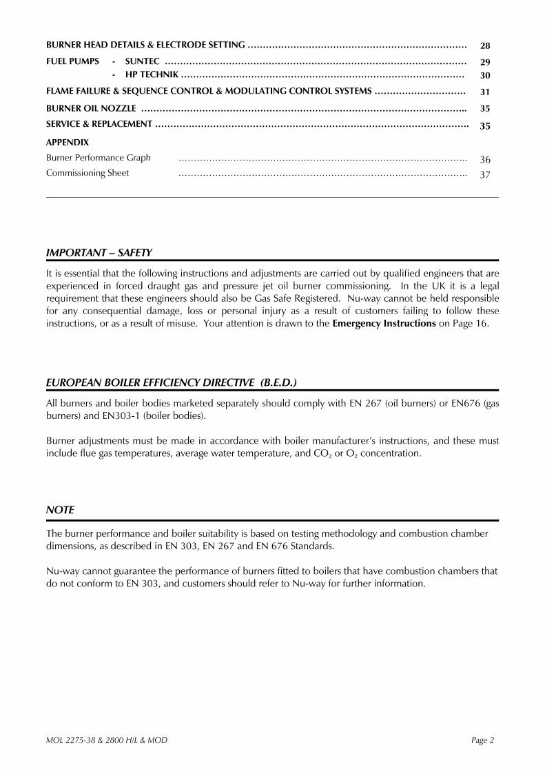
Electrical Data MOL 2800 Modulating and High/Low Burners
Control Fan Motor Main Burner MCB Size Fan Motor MCB Size Overload Cable Size
MOL 2275-38 H/L 5 Amp 5.5 kW 3 x 16 Amp 8.0-12 2.5mm2
MOL 2800-38 H/L 5 Amp 7.5 kW 3 x 20 Amp 11-16 Amp 4mm2
MOL 2800-38 Mod 6 Amp 7.5 kW 3 x 20 Amp 11-16 Amp 4mm2
MOL 2800-41 H/L 6 Amp 11.0 kW 3 x 32 Amp 19-27 Amp 6mm2
MOL 2800-41 Mod 6 Amp 11.0 kW 3 x 32 Amp 19-27 Amp 6mm2
MOL 2800-44 H/L 6 Amp 15.0 kW 3 x 40 Amp 26-35 Amp 6mm2
MOL 2800-44 Mod 6 Amp 15.0 kW 3 x 40 Amp 26-35 Amp 6mm2
Pumping Unit details Pump Motor Main
Burner Pumping Unit Motor MCB Size Overload Cable Size
MOL 2275-38 H/L
MOL 2800-38 H/L The MOL 2275-38 & MOL 2800-38 H/L have a pump driven from the fan motor.
MOL 2800-38 Mod 1.5 kW x 1425 rpm 6 Amp 2.7-4.2 Amp 1.5mm2
MOL 2800-41 H/L 1.1 kW x 1425 rpm 4 Amp 1.8-2.8 Amp 1.0mm2
MOL 2800-41 Mod 1.5 kW x 2800 rpm 6 Amp 2.7-4.2 Amp 1.5mm2
MOL 2800-44 H/L 1.1 kW x 1425 rpm 4 Amp 1.8-2.8 Amp 1.0mm2
MOL 2800-44 Mod 1.5 kW x 2800 rpm 6 Amp 2.7-4.2 Amp 1.5mm2
MOL 2275-38 & 2800 H/L & MOD Page 8

INTRODUCTION This manual has been produced to enable users to install, commission and use MOL modulating burners safely and efficiently. The manual covers two types of burner: High/Low and Modulating (Class D fuel). At each stage the conditions which should be met and the adjustments and other actions which should be carried out are detailed and the locations of the various components and adjustment mechanisms are identified. Where appropriate, this information is supported by tables and graphs. Literature on the proprietary components used in MOL systems is available on request. FEATURES Developed through extensive field experience in the UK and overseas markets, the MOL series meets the current known test authority requirements in these markets and sets new standards in efficient and reliable operation. MOL modulating burners are designed for flange mounting to the appliance frontplate and they are delivered ready to install with a pre-wired packaged control system and oil pumping unit. (See Modes 1, 2 & 3:Page 11) Burner Nominal Capacity MOL 2275 2300 kW MOL 2800 2750 kW Controls and Safety Systems MOL burners are fitted with an automatic sequence/flame failure control and photoelectric cell for continuous flame supervision. A combustion air flow control coupled to an oil nozzle pressure control system ensures smooth starting and optimum operating efficiency. Operating Mode In standard form the MOL Modulating burner can provide a turndown range of up to 3:1. The High/Low version will be limited to a maximum of 2.5:1. Fuels MOL burners covered in this manual are designed to fire distillate fuel. SITE CONDITIONS AND SERVICES Flue and Chimney Requirements It is important that: The flue pipe from the appliance and the joint between this flue and the chimney are sealed to prevent leakage of combustion products.
The flue pipe from the appliance does not protrude into the chimney beyond the inside wall. The top of the flue or chimney shall be higher than any roof within a radius of 10 metres. Checks are made to ensure that the chimney is suitable for oil fired appliances and that the proposed installation complies with all Local Authority and other regulations covering such installations.
If more than one appliance is connected to a common flue or chimney the cross-section of this flue or chimney should be adequate for the total volume of combustion products from the appliances. It is recommended that each appliance should be exhausted into a separate flue.
Plant Room Ventilation The burner must be supplied with dust-free air at sufficient rates for all firing conditions, in accordance with the appropriate standards. Existing Appliances The appliance should be prepared for installation of the MOL burner by thorough cleaning, including the removal of all adhering tar, scale and dirt. An inspection should also be carried out to ensure that the appliance is in good condition. Any doubt about the appliances suitability for oil firing shall be referred to the appliance manufacturer. MOL2275-38 & 2800 H/L & MOD Page 9

Combustion Chamber Conditions The combustion chamber conditions should not exceed those shown on page 36 of this manual. Burners working with zero rated combustion chamber conditions can be subjected to a maximum negative condition of 0.05 kPa (0.5 mbar) Oil System Refer to the drawings on pages 12, 22 & 23 for details of the burner oil system. Oil Supply to the Burner The oil supply from the storage tank to the burner may be provided by: a. Single pipe gravity feed system b. Pumped ring main system Single Pipe System The height of the main storage tank above the burner and the sizing of the pipe to the burner must be designed so that the oil pressure at the burner oil pump inlet is not less than 35 kPa (0.34 bar). The maximum oil pressure at the burner pump inlet must not exceed 500 kPa (5.0 bar) under any operating conditions. The pipe must be sized to the full swept volume of the burner oil pump and not the capacity of the burner nozzles. Pumped Ring Main System The pumped ring main is the preferred system of oil supply and is essential for multiple burner installations.
The ring main pumps and supply pipework must be designed to cater for 1.25 times the total swept volume of the burner oil pumps connected to the supply system.
All oil supply pipes must be constructed and installed to comply with local conditions and appropriate codes of practice and standards. All pipework must be firmly supported and a Pressure Reducing Valve (PRV) should be fitted to control the supply pressure. Burner Pump Capacities The oil pumps used on Nu-way modulating oil burners are listed in the table on page 29 & 30. It is essential that the full swept volume of the pump be considered when oil supply lines or ring main systems are calculated. Filtration When using fuel oils filtration of the oil is essential. The filtration system should be chosen according to the individual features of the installation. The oil supply diagram on page 12 gives guidelines. When the oil supply pressure is checked then this should be measured at the burner pump vacuum gauge port to allow for any pressure drop across the filters.
Failure to provide a good clean oil supply will almost certainly lead to premature wear and rapid failure of the oil pump unit. Electrical Power Supply A three phase 50Hz supply is required (60 Hz Burners are available on request). Power requirements are tabulated in the Appendix of this handbook. The power supply provided must comply with all relevant Codes and Standards. MOL 2275-38 & 2800 H/L & MOD Page 10
UNPACKING and ASSEMBLY To safeguard against damage in transit, MOL modulating burners may be supplied in partly assembled form in one of three alternative modes: Mode 1: The complete burner unit fully assembled. Mode 2: Burner body complete with control panel. Combustion head hinged extension and flame tube
assembly. To assemble the burner: Assembly of the burner can be completed after fitting the hinged extension/flame tube
assembly to the appliance. Alternatively, fit the extension/flame tube assembly to the burner body using the four nuts and
washers provided. The pumping unit is supplied as a separate component to modes 1 and 2 and is inclusive of flexible pipes to make all the necessary oil connections. Mode 3: On request, MOL modulating burners can be supplied in a fully assembled compact
configuration. These burners include the oil pumping and conditioning unit mounted beneath the burner body and are pre-piped, requiring only the connection of fuel and electrical supplies to complete the installation. The suitability for installation of compact modulating burners should be referred to the appliance manufacturer as the addition of the oil pumping unit adds extra weight to the appliance frontplate.
MOL 2275-38 & 2800 H/L & MOD Page 11
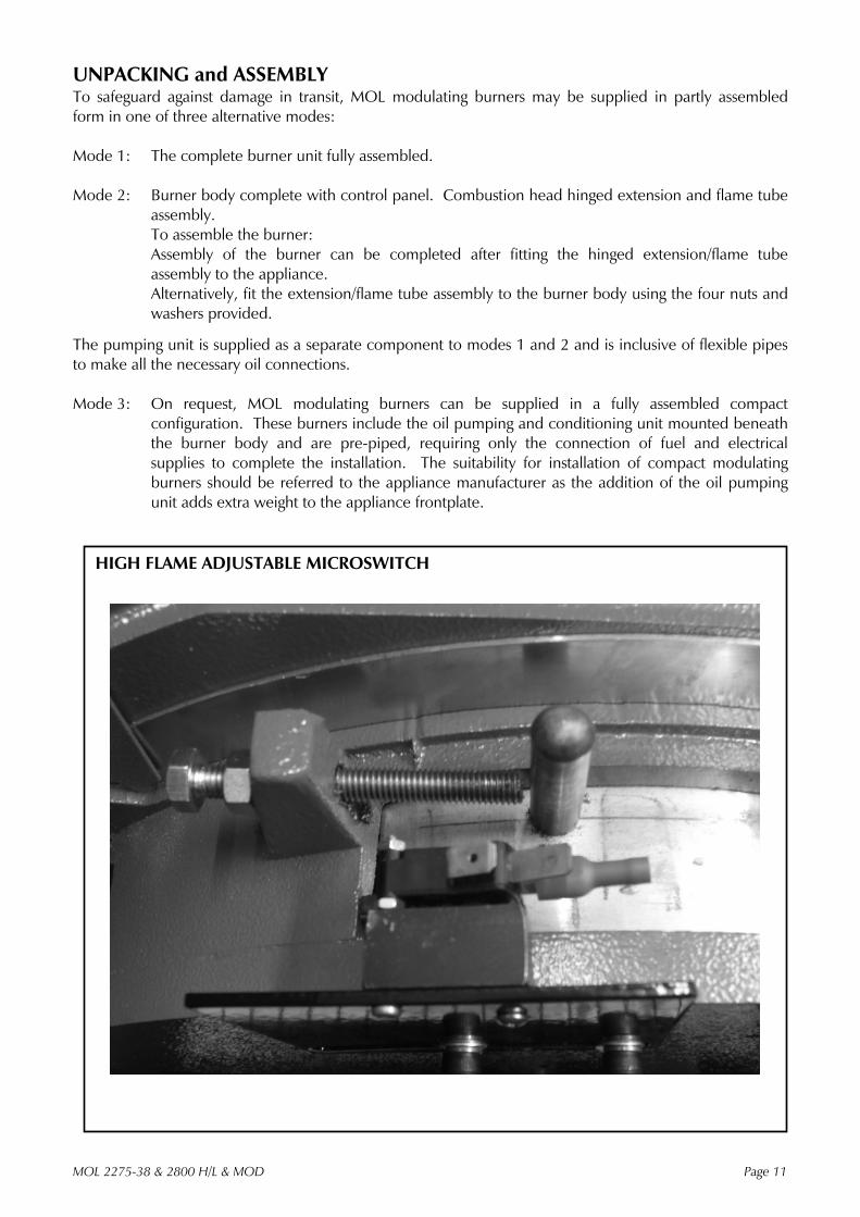
HIGH FLAME ADJUSTABLE MICROSWITCH

MOL2275-38 & 2800 H/L & MOD Page 12
BURNER OIL SYSTEM
Pumped Systems – All Modulating Burners
All interconnecting pipework to be minimum 19mm and pressure rated for 42 kg/cm2 (600 psi).
All burners require a pump inlet pressure of 0.35 to 0.70 kg/cm2 (5 to 10 psi).
If a shut-off valve is fitted in the inlet line, a pressure relief valve set at 0.7 kg/cm2 (10 psi) above the supply pressure must be fitted to prevent damage should the valve be left shut during burner.

INSTALLATION General Ensure that the appliance is suitable for the heat input of the burner. If there is any doubt in this area, reference shall be made to the appliance manufacturer. Detailed burner performance data are presented in the appendix of this handbook. Fitting to the Appliance If the burner is to be fitted to a new appliance refer to the appliance manufacturers recommendations.
If the burner is to be fitted to an existing appliance a mounting flange must be provided as detailed in the section of Burner & Components Identification. Ensure that the joint between the burner and the mounting flange is sealed effectively using the gasket provided.
The flame tube should not extend beyond the inner face of the appliance combustion chamber unless the appliance manufacturer specifies extensions, for example in the case of reverse flame boilers. Connections Once the burner is mounted to the appliance, open the hinged extension by removing the two nuts and washers, connect the HT leads to the ignition electrodes and close and fasten the extension.
Connect the flexible oil pipes between the burner and the pumping unit by referring to the burner component and pumping unit drawings on pages 5,6 & 15.
Connect the oil supply to the burner pumping unit with reference to the oil system diagrams and pumping unit drawings on pages 12, 22 & 23. Electrical Power Connection Connect a three-phase, 50 Hz electrical supply to the burner, observing all applicable Codes and Standards. The electrical connections required are shown in the wiring diagram contained in the instruction pack attached to the burner. These diagrams also show the auxiliary control connections, which must be made.
If the burner is supplied as part of a packaged appliance/burner unit, refer to the appliance manufacturers instructions. New Wiring Colours In accordance with the Requirements for electrical Installations BS 7671:2001 Amendment No.2 (the IEE wiring regulations), wiring colour coding has been amended to Brown (L) and Blue (N) for single phase power circuits, and Brown (L1), Black (L2), Grey (L3) and Blue (N) in three-phase power circuits from 1st June 2006. Full details of the changes can be found in amendment No.2 9AMD 14905 to BS 7674:2001 – which is a free download from the IEE website (www.iee.org/cablecolours). They are also within the new version of BS 7671:2001 (Incorporating Amds 1 & 2) published on 31st March, this new version of the Wiring Regulations can be identified by its brown cover. MOL 2275-38 & 2800 H/L & MOD Page 13

All personnel concerned with commissioning and/or operation of MOL burners shall familiarise themselves with the information presented in this section.
BURNER OPERATION - MODULATION
Burner Description Nu-way MOL modulating series fully automatic oil burner units are of packaged design and meet relevant National and International standards based on the ISO system of measurement and fastening.
A system of pressure atomisation employing a single spill-back nozzle is used throughout the range. If the burner is equipped with the Nu-way Electronic Cam Modulating (ECM) system, then reference should also be made to the supplementary documentation supplied with this handbook. In the case references to the RWF40 Universal Controller and Modulating Unit within this handbook can be ignored.
The standard method of operation is based on the Siemens RWF40 Universal Controller, which has been designed for use in oil and gas fired installations, where it provides temperature or pressure control of modulating burners with continuously adjustable fuel throughput.
The control output of the RWF40 is a potential free 3-position switch, which is used for the control of reversible motors. The control signals for the Open (Y1) and closed (Y2) are indicated on the controller face by light emitting diodes.
For further information on the RWF40 and its associated components, please refer to the data provided on page 33 of this handbook.
When the boiler control calls for heat, the burner modulating unit will travel to the ‘high flame’ position and interlock the control circuit. An air pre-purge will take place at this position for a pre-determined period, at the end of which the burner sequence controller will stop until the modulating unit has travelled to the ‘low flame’ position and interlocked the control circuit again. The sequence control will now recommence its operational cycle and the burner will light and remain at low flame until the high flame release signal is given by the sequence control.
The modulating unit will now move to high flame and remain at this position until the desired boiler temperature/pressure is attained. From this stage the modulating unit will commence to move towards the low flame position between low and high flame. BURNER OPERATION – MOL 2800-41 & 44 HIGH/LOW The oil system operates at constant pressure and utilises four nozzles in order to minimise nozzle size, thus producing the fine atomisation necessary for efficient combustion.
The air regulator is of a rotary type and is hydraulically actuated. Access by removing the top cover from silencer box and air adjustments by set pins operating against stop on moveable part of regulator.
An adjustable microswitch is actuated by the moving air regulator. The microswitch controls the air/oil phasing on the change from low to high flame. The switch also proves that the air regulator is moving before high flame is allowed to spray. The microswitch controls an additional, normally open, solenoid valve. BURNER OPERATION – MOL 2275-38 & MOL 2800-38 HIGH/LOW This oil system also operates at constant pressure but with two nozzles to compensate for the reduced throughput at high pressure and the smaller diffuser required.
Air regulation is by a pivoted flat blade fitted into the air inlet and is operated by a hydraulic ram. Adjustment is by adjustable screws restricting the movement of the operating arm and access is obtained by removal of the linkage cover from the end of the inlet casting.
Oil flow is obtained when the magnetic valve is energised and the burner fires on low fire. A second valve is energised when high fire oil and air is required. MOL 2275-38 & 2800 H/L & MOD Page 14

BURNER CONTROLS Burners are supplied with an integral control panel containing a sequencing control unit and the burner switchgear. On steam boiler applications an auxiliary control panel containing boiler feed pump controls, water level interlocks and alarms is available. Oil Pumping Units Standard burners are supplied with a floor-mounted pumping unit. Details of which are shown below. On burners supplied in ‘compact’ configuration, the pumping equipment is mounted on the burner. Modulating Unit The modulating unit consists of a reversible servomotor, which is directly coupled to the camshaft of the modulating unit. Two adjustable cams are mounted on this shaft, one of which is connected to a flexible cable operating the burner air inlet control damper and is of the variable contour type (see fig 2 on page 20). The second cam is the modulating oil cam and is illustrated in fig. 1. The Burner Oil System drawing on page 12 shows the hydraulic circuits. Oil for combustion is drawn from the supply through a fixed displacement pump and supplied direct to the burner nozzle. A return line from the back of the nozzle is connected to a ‘spill regulating valve’ which regulates the oil pressure at the nozzle according to the position of an internal piston which is actuated by the oil control cam in the modulating unit.
There is a well-defined relationship between the delivery of fuel through the nozzle and pressure behind the nozzle, therefore movement of the oil cam ‘modulates’ the nozzle output and hence the output of the burner.
The volume of air required for combustion must also be varied as the nozzle output varies, and this is done by the air control damper, operated by a flexible steel cable connected to a lever system bearing against the air control cam.
Once the oil has been adjusted as described in the Commissioning procedure section of this handbook, the profile of the air cam is adjusted to give the desired combustion conditions by turning the thumbscrews under the cam in or out as the burner is ‘inched’ through its firing range.
The air control damper is spring-loaded ‘open’ for safety in the event of cable failure. MOL2275-38 & 2800 H/L & MOD Page 15
OIL PUMPING SET
Pipework Connections Item Description R”
1 Oil Inlet Connection 1 2 Oil Return Connection 1 3 Burner Oil Feed 3/4 4 Burner Oil Return 3/4
COMMISSIONING IMPORTANT – SAFETY It is essential that commissioning shall be undertaken only by suitably qualified and experienced personnel. In the case of MOL modulating burners, commissioning engineers should be experienced in pressure jet oil burner commissioning. Nu-way can accept no responsibility for consequential loss, damage or personal injury which results from a failure to follow the commissioning instructions provided or from commissioning procedures being undertaken by unqualified personnel. EMERGENCY INSTRUCTIONS MOL modulating burners are designed and constructed to meet current legislation. When used in accordance with the instructions provided, MOL modulating burners are unlikely to produce a hazardous condition. If, however, such a condition should arise in connection with the burner, the appliance or of any instrument, machine or service in the vicinity of the burner, the OIL AND ELECTRICITY SUPPLIES SHALL BE ISOLATED IMMEDIATELY and they shall remain isolated until the fault has been identified and rectified. Inspection Before commissioning is begun it is important to: Check that the electrical wiring is complete and complies with all applicable Codes and Standards.
Ensure that the fuses are fitted and are of the correct rating.
Check electrical earthing.
Verify that the oil supply system is correctly designed and that the supply pipework is correctly sized and free from leaks.
Ensure that all manual fuel isolation valves are operable, fully closed and leak tight.
Make all personnel involved in the commissioning aware of the location of the emergency fuel and electricity isolation points.
Check that fittings for bleed and pressure testing are fitted.
Establish that the appliance is in an appropriate and safe condition to be fired: for example, that there is water in the boiler.
Set the appliance’s ventilation and flueing arrangements.
Ensure that any warning notices appropriate to the commissioning procedure are in position.
Ensure that all tools and test equipment are available and ready for use. Essential items include temperature measuring instruments for measuring flue gas and appliance water temperatures, and a means of analysing the flue products for carbon dioxide (CO2), oxygen (O2), carbon monoxide (CO) and smoke.
Check that all relevant documentation is available including, where appropriate: - The agreed plant performance specifications - Plant drawings and pipework diagrams - Certificates confirming satisfactory completion of procedures such as soundness testing and
electrical safety tests. - Commissioning, operating and maintenance instructions for the plant.
Establish that the operation of plant other than that being commissioned will not have an adverse effect on the operation of the plant to be commissioned and similarly, that the operation of the plant to be commissioned will not have an adverse effect on other plant.
Confirm that the operation of adjacent plant and machinery will not constitute a hazard to the personnel involved in commissioning.
MOL 2275-38 & 2800 H/L & MOD Page 16

Pre-firing Checks and Dry Run
With the oil and power switched off, carry out the following checks:
Check the nozzle size and position relative to the diffuser plate. (The burner head dimensional details are given in the appendix of this handbook).
Check that the electrode positions and HT leads are correct.
Check all the motor overload settings.
If the appliance is a boiler, check that the water level is correct, the controlling valves are open and that the water pumps are in working order.
If a flue damper is fitted, check that it is correctly interlocked to the burner or fixed in the fully open position.
Ensure that there is a good oil supply to the burner pump. Bleed one or two gallons from the flexible to eliminate any pipe scale and air from the system.
Check that the oil supply is of the recommended temperature and pressure.
Bleed the burner pump manually by removing the right-hand ¼” BSP plug in the top of the pump until air-free oil flows.
Switch on the electricity supply to the burner and check that the pump motor rotation is correct to the direction arrows shown on the pump face.
Modulating Burners
Remove the access lid on the modulating cam box unit.
Switch on the burner at the control panel. The modulating unit cam shaft should now rotate to the high flame setting, and the combustion air motor will start the air pre-purge phase.
Allow the fan motor to run up to speed, switch off the burner and check the fan rotation (anti-clockwise as viewed from the motor side) as the fan slows down.
Remove and cover the photoelectric cell with a clean lint-free cloth, switch on the burner, and allow it to run through to lockout. During this run check that the ignition spark is occurring, and note the spill and line oil pressures at the moment of ignition. Reset the sequence control and repeat the run if necessary to check these functions.
If necessary, adjust the spill pressure to the correct figure according to the nozzle specification and the line pressure at the burner pump to 27.8 bar (400 psi).
MOL 2275-38 & 2800 H/L & MOD Page 17

High/Low Burners
Check that the total nozzle size is correct for the particular application. The normal operating pressure of the burner is 20 atm (20.7 bar : 300 lbf/in2). To obtain nozzle throughput in Imperial gal/h multiply marking by 1.44. To obtain nozzle throughput in litres per hour multiply by 6.55, and for kg/h multiply by 6.2.
Check ignition electrodes and leads and the position of the nozzles relative to the face of the diffuser.
When replacing the inner assembly ensure that the ‘O’ rings are correctly in position between the union blocks.
Check that all controls and flue dampers are correctly set.
Turn switch on control panel to ‘low flame hold’ and ensure that there is water in the boiler.
Remove and cover the photoelectric cell with a clean lint-free cloth, switch on the burner, and allow it to run through to lockout. during this run check that the ignition spark is occurring, and note the pump pressure.
For MOL 2800 41 & 44 Models only
The works setting of the air regulator is 6mm (¼”) open for low flame and 19mm (¾”) for high flame. The sequencing microswitch is set to bring in high flame oil after the air regulator has moved from 6mm (¼”) away from the low position. The air regulator is adjusted by means of set pins acting on a stop carried on the moving member of the regulator.
Access to the set pins and the sequencing microswitch is obtained by removal of the plate at the top of the silencer.
For MOL 2275-38 & MOL 2800-38 Models only The recommended air damper setting on this burner at the start of the test should be approximately 20° for low and 40° for high fire. Adjustment of both angles will be necessary during the commissioning procedure and is made with the screwed stops under the linkage cover. See Fig 9, page 23. THE BURNER IS NOW READY TO BE COMMISSIONED MOL 2275-38 & 2800 H/L & MOD Page 18

COMMISSIONING - MODULATING BURNER Hand Auto Selector Switch This switch must always be in the ‘Auto’ position when the burner is required to start. The ‘Hand’ selection can be made immediately the burner has started to fire.
Should the burner be left in the ‘Hand’ position it will NOT modulate until the ‘Auto’ position is selected. Commissioning the Burner New MOL 2800 modulating burners are generally supplied against the firing specification of the appliance. In this case the system and spill pressure may be pre-set and require checking and minor adjustments only. The following section describes how to set up the modulating cam box unit from a ‘scratch’ situation. The modulating cam layshaft can be rotated by hand using the gearbox disengagement lever in the drive servomotor. Ensuring that the modulating cam arrangement is in the low flame position, adjust the oil cam (see fig 1,
page 20) so that it gives approximately 1.5mm throw (3mm stoke and lock in position).
Check to ensure that the spill valve push rod bears lightly against the oil cam.
Turning to the air cam (fig.2) rotate the thumbscrews in or out so that they give a reasonable amount of adjustment in each direction. Adjust the flexible cable (at either end if necessary) until the air inlet damper is fully closed (i.e. until all the slack is taken up on the cable).
Note: Cams one and two control the high (cam one) and low (cam two) limits of the mechanism. These are factory set and should not require any adjustment. However, in extreme circumstances the angle of rotation can be reduced by adjustment of the appropriate cam. Any adjustment made will alter the oil spill pressure.
Now adjust the thumbscrews to give a small opening of the air damper at low flame.
Uncover and replace the photocell. Reset the sequence control and allow the burner to start. Immediately the burner starts, switch the hand/auto selector switch to the ‘hand’ position and hold low flame until the appliance is ready to accept high flame. During this period, check and adjust the low flame oil throughput.
Check the flame visually. If the flame is dirty, adjust the air cam thumbscrews until the flame becomes clean.
After a suitable delay, inch the camshaft to the high flame position (i.e. through 180) by means of the inching switch on the control panel. Adjust the air cam profile by means of the thumbscrews until the air damper is now fully open. At this stage it will be found that all of the thumbscrews between low and high position will require adjusting so as to avoid over stressing the cam profile band.
Once this has been done, there should be a fairly smooth profile between low and high positions. Ensure that the flame is visually clean throughout the modulation range at all times. MOL 2275-38& 2800 H/L & MOD Page 19

MOL 2275-38 & 2800 H/L & MOD Page 20
MODULATING UNIT (Cams shown in the Low Flame Position)

Check the oil consumption. If this is not correct for the full burner rating, the oil cam must be adjusted as follows:- a. Inch the burner to low flame and note the spill pressure
b. To increase the minimum rate, adjust as shown in fig.1.
c. Adjust the cam to give more eccentricity for more oil at high flame, and vice-versa.
d. Return to the minimum setting and compensate for any changes.
e. Inch the burner to high flame and again check the oil flow.
Continue to repeat a. to d. until the high flame oil rate is correct.
When a satisfactory setting has been achieved, lock the air cam thumbscrews with the grubscrews fitted in the face side of the cam body. Refit the Modulating unit access cover.
Check the function of the air pressure switch:
Switch off the electrical supply to the burner.
Remove the air pressure switch cover. Fit a manometer to the pressure switch to check the actual air pressure against the pressure switch dial setting.
Switch on the electrical supply and allow the burner to establish low flame.
Select ‘Hand’ control and ensure that the burner is at low flame by using the inching switch.
Slowly turn the air pressure switch adjusting dial clockwise until the flame is extinguished. The burner will go to lockout.
Turn the dial one division anticlockwise and reset the burner lockout. The burner will now continue through its cycle until flame is established or the burner goes to its lockout position. If the burner goes to lockout repeat the procedure one division per burner cycle until flame is established. Once successful turn the dial a further two divisions anticlockwise.
Switch off the burner electrical supply, replace the air pressure switch cover and remove the manometer.
If the burner control is inclusive of Low, Excess Low and High Water interlocks and alarms, test that these function correctly. Ensure that the boiler feed pump switchgear provided in the panel is operating satisfactorily.
Adjust the boiler to attain the correct working pressure/temperature and adjust the on/off and limit instruments to the desired values.
Switch the Hand/Auto selector switch to ‘Auto’. The plant is now under the control of the pressure/temperature controllers for modulation and the on/off and high limit instruments for control.
Finally check ancillary controls and equipment such as damper interlocks etc. MOL 2275-38 & 2800 H/L & MOD Page 21

COMMISSIONING – ALL HIGH/LOW BURNERS LOW FLAME
Switch on electricity supply. If controls are correctly set, burner fan will start, followed by oil pump, providing air pressure switch changes over. Check rotation of each.
Air pressure switch is works set at 50mm wg, but may have to be adjusted to suit installation.
After pre-purge period has elapsed the low flame solenoid valve will open allowing oil to spray through the low flame nozzle only and be ignited by the HT spark which is already present.
The photo-electric (PE) cell should take over and burner will run.
At this stage adjust the air regulator to give a visibly clean flame.
Do not fire the burner for long periods until warming up of appliance is completed. During warm-up check lockout period by ‘blacking-out’ PE cell while burner is firing: burner should stop within one second.
Keep PE cell covered: after between 20 and 40 seconds burner should start its cycle again. It should lock out five seconds after the low flame solenoid valve is energised. The air regulator should now be set to give a CO2 reading of 10-11% with a smoke number of 0-1. HIGH FLAME When the appliance is ready to be fired at high flame, move switch on control panel to this position. The two high flame solenoid valves will be energised. The normally closed valve will open and allow pressurised oil to pass to the hydraulic cylinder actuating the air regulator. At the same time the other, normally open, high flame solenoid valve will close to prevent oil reaching the high flame nozzles until the air regulator has moved and actuated the sequencing microswitch.
For MOL 2800-41&44 models only: The micro switch controls this second high flame valve and should be adjusted to give a clean changeover from low to high flame. (See page 11)
With the burner operating on high flame adjust the air regulator to give a CO2 reading of 12-13% and a smoke number of 0-1.
If silencer has been removed, refit and again check CO2 and smoke readings, readjusting the air regulator if necessary.
MOL 2275-38 & 2800 H/L & MOD Page 22
BURNER OIL SYSTEM 2800-41 & 44 HIGH/LOW BURNERS

MOL 2275-38 & 2800 H/L & MOD Page 23
BURNER OIL SYSTEM – MOL 2275-38 & MOL 2800-38 HIGH/LOW BURNERS
Fig. 9
AIR DAMPER ADJUSTMENT - MOL 2275-38 & MOL 2800-38HIGH/LOW BURNERS

FINAL CHECKS 1. Check that all covers have been replaced and that all locking devices are secure.
2. Check the operation of the appliance control instruments and safety interlocks.
3. Ensure that the appliance safety controls and any other interlocks are set to safe limits.
4. COMMISSIONING IS NOW COMPLETE.
5. Establish the electrical supply to the burner and switch on the burner. Allow the burner to proceed through its operating sequence until it is operating on high fire. The burner will now operate normally until:
a. It is switched off by the appliance controls.
b. It is switched off manually.
c. There is an electrical power failure. In this event the burner will restart and run normally when power is restored. No manual intervention is required.
On Completing Commissioning
When commissioning has been completed satisfactorily the commissioning engineer shall prepare a report, which shall contain the following:
1. Details of any modifications made to the system, together with revised drawings if necessary.
2. Customer and plant details, including any serial numbers.
3. Operating levels and settings, including flue gas analysis information. This report shall be passed to the person responsible for the plant. This responsible person shall ensure that:
1. All personnel concerned with operating, supervising and maintaining the plant receive instruction covering:
- The way in which the plant operates and the locations and functions of the plants safety systems.
- The correct light-up and shutdown procedures.
- Adjustment of operating variables.
- Checking of plant interlocks.
- The plant’s maintenance requirements.
- The actions to be taken in the event of a fault condition.
2. Clear light-up and shutdown procedures are displayed on the plant and that the pipes, valves and switches involved are clearly marked.
3. CLEAR AND CONCISE EMERGENCY SHUTDOWN PROCEDURES ARE DISPLAYED. MOL 2275-38 & 2800 H/L & MOD Page 24

ROUTINE MAINTENANCE OF MOL BURNERS General It is vitally important that personnel responsible for the day to day operation and maintenance of the plant are instructed by the commissioning engineer on the basic function of the burner, as well as the need for routine maintenance and daily checking of burner operations. Final adjustments, which will have been made during the commissioning, must be recorded on the Commissioning Sheet at the back of this manual and in the appliance log book. A copy of the commissioning data must be sent to the appliance manufacturer. The burner should be kept clean inside and out. It will be more reliable, and if an oil leak occurs it will be spotted more readily. Daily Checks Inspect the burner daily to check if there is any variation from the correct operating sequence, as follows: Check the oil pressure on the nozzle line gauge. This should be 27.8 bar (400 psi). If the oil pressure is low, then check the oil supply system, stop/fire valves, ring main pumps, etc. Check the spill pressures. If these are low it may indicate that the oil nozzle filter is clogged. If there is an inspection window on the appliance through which the ignition spark and flame can be observed, ignition and flame should be inspected and any irregularities that are observed should be rectified, i.e. nozzle/electrodes cleaned and any deposits removed from the inside of the flame tube and diffuser. Replenishing the Fuel Supply It is usual practice to shut boiler(s) off whilst delivery of fuel is being made and allow approximately 30 minutes for any sediment to settle before restarting the burners. Boiler Combustion Services Keep the boiler combustion surfaces and flueways clean. Any accumulation of soot will decrease the efficiency of the boiler and increase the flue gas exit temperature. Always cover up the burner during boiler cleaning operations. Inner Assembly Removal – MOL 2800-41 & 44 High/Low Burners The inner assembly, comprising the nozzle block and diffuser plate, can be removed through the burner casing. First switch off the electricity supply to the burner, remove the burner casing top cover (eight screws). Disconnect the Allen screw securing the outer manifold to the inner manifold, located on the right-hand side of the burner casing. Note that these two manifolds are sealed together by ‘O’ rings. The solenoid valves, pressure gauges, etc, are now released from the outside of the burner casing. They may be supported, while the burner inner assembly is removed, by entering the Allen screw through the outer manifold into the (tapped) boss provided for the purpose in the burner casing immediately below the normal manifold location. Remove the two nuts securing the inner manifold to the inside of the burner casing. By grasping the inner assembly pipes the complete inner assembly/diffuser can be withdrawn from the casing. The diffuser plate is mounted on a bracket clamped to the nozzle assembly. The front of the nozzles should be set approximately 12mm (½”) behind the diffuser face. The diffuser should be set 102mm (4”) back from the front of the flame tube. The position can be adjusted if necessary. If the burner has one low flame nozzle (the upper one) the ignition electrodes are set on this nozzle. If there are two low flame nozzles the ignition electrode should be set over the top left-hand nozzle (as viewed from the front, or boiler side of the burner). MOL 2275-38 & 2800 H/L & MOD Page 25

Inner Assembly Removal – MOL 2275-38 & MOL 2800-38 High/Low Burners The nozzle block can be withdrawn through the top of the burner casing:-
After switching off the electrical supply to the burner, remove the casing top cover held in place with four screws.
Disconnect the two Allen screws holding the two halves of the brass manifold together, these are located on the right-hand side of the case. Be prepared to catch any free fuel oil that may fall when sealing ‘O’ rings are freed.
Grasp the two inner oil pipes and withdraw the inner assembly from the case. It will be necessary to support the weight of the nozzle block when the front support ring detaches from the diffuser assembly, this assembly is attached to the blast tube and will stay in place. See Fig. 1 below. Inner Assembly Removal – Modulating Burners Switch off the electricity supply to the burner and disconnect the flexible oil lines at the burner head quick release couplings.
Remove the hinge plate retaining nuts and swing open the burner. Disconnect the HT leads and remove the two long cap head screws retaining the inner assembly, from the face of the oil manifold block on the side of the hinged extension.
The inner assembly lance can now be removed complete with the diffuser and electrode assembly. It is important that the nozzle is cleaned using non-abrasive materials, never use anything which may scratch the finely finished surfaces of the nozzle.
Nozzle life is approximately 5000 hours operation, after which wear will affect atomisation and plant efficiency will drop. Photoelectric Cell Remove the photoelectric cell and clean with a soft lint-free cloth if necessary. Be careful not to touch the glass bulb of the cell as this can lead to premature failure of the unit. Access to the air regulator is by removal of the silencer.
To remove:
1. Take off guard at inlet.
2. Remove two nuts securing silencer to casing accessible from underneath.
3. Take off two remaining nuts through top cover and remove silencer. BURNER COMBUSTION HEAD – MOL 2275-38 & MOL 2800-38 HIGH/LOW MOL 2275-38 & 2800 H/L & MOD Page 26
Fig. 1
FAULT FINDING
If the Burner Fails to Start
Make sure that all the thermostats and switches in the control circuit are in the ‘made’ position and that the oil pre-heater ‘excess limit’ thermostat has not tripped. Reset if required. Check that the low oil temperature thermostat is set correctly for the appropriate fuel. Check that the electricity supply to the burner is ‘live’ and that the control and main circuit fuses are intact. If a fuse is found to be ‘blown’ then the cause should be investigated and rectified before proceeding further.
On steam boilers, check that the ‘water level interlocks’ are in the ‘made’ position.
If the burner is found at lockout (red lockout lamp illuminated) Reset the burner and observe the starting sequence. (make reference to the Sequence Diagram and Timing Charts for the Flame Failure controls on page 31 & 34 for further information.
Check the fan and oil pump motor overloads and reset if necessary.
Check the operation of the air pressure switch. Failure of the switch to operate prevents the oil pump from starting. Flame Occurs Followed by Immediate Lockout
Check the PE cell and the air regulator for correct operation. Check that the oil pressures are correct. If necessary, check and clean the pre-heater hot oil filter, ensure that there is sufficient oil in the storage tank, bleed the oil pump in case it is partially air-locked. Check to ensure that all stop/fire valves in the supply line are fully open. Check residual fuel oil temperature – check the ring main for correct operation in respect of temperature and pressure. The Burner Starts With The Correct Oil Pressure But No Flame Appears
Check the ignition system, HT lead connections, electrode gap and the condition of the electrode insulators. Check that the nozzle cut-off is functioning and that the air damper cable is not broken or disconnected (the air regulator will be fully open). It is important to note that continued re-setting of the burner should be avoided as this can lead to a dangerous situation. Modulating System
If malfunction of the modulating controller RWF 40 is suspected, check that only compatible components such as the range insert and pressure/temperature detector have been used. If problems persist then replacement of the unit should be considered. Burner Commissioning Sheet
This manual contains a record of the essential information and will have been completed by the commissioning engineer with individual details of the burner. These details should be verified periodically and adjusted if variations are noted. Commissioning details must also be record in the appliance logbook. MOL2275-38 & 2800 H/L & MOD Page 27

BURNER HEAD DETAILS & ELECTRODE SETTING
MOL 2275-38 & 2800 H/L & MOD Page 28
ALL MODULATING BURNERS
MOL 2800-41 & 44 HIGH/LOW BURNERS 6 3
8
13

FUEL PUMPS Suntec Series TV Pressure Regulating Valve (For use with Suntec series ‘T’ pumps) The TV valve is designed for use with the Suntec series ‘T’ fuel pumps, see diagrams. This separate pressure-regulating valve, which is installed in the nozzle line, is designed to keep constant pressure even if the output capacity is changed. A built-in dampening device absorbs vibrations in the valve, effectively eliminating pulsations in the nozzle line. Pressure adjustment Remove the cap nut (1), washer (2) and loosen the locknut (4). Turning the screw (3) counter-clockwise will decrease the nozzle line pressure and visa-versa. After adjustment, tighten the locknut and refasten the washer and cap nut. OIL PUMP DETAILS General Notes: Pump rotation is quoted by the direction of the pump shaft as viewed from the shaft side. The direction arrow embossed on the face of the pump or pump nameplate is therefore the reverse of the quoted rotation.
The Oil Pump is completely pre-piped as part of the pumping or pumping and heating set.
Should the Oil Pump performance become suspect then a replacement unit should be obtained and the Oil Pump returned to determine its serviceability.
Upon replacement refer to the pump bleeding instructions in the section Pre-firing Checks on page 17. Further details regarding the Oil Pump unit can be supplied on request. PUMP CAPACITY HP Technik VBGR = 1150 l/h
Suntec T2C = 1450 l/h
Suntec E7 & J7 = 355 l/h SUNTEC Type T OIL PUMP Technical Data General: Hydraulic data: Mounting: Flange mounting Nozzle pressure range: 40 bar max Conn threads: Cylindrical according to ISO 228/1 Operating viscosity: 4-450 cSt Shaft: 20mm ø Oil temperature: 0-140° max in the pump Weight: 7.8 kg Inlet pressure - Light oil: 0.45 bar max vacuum to prevent air separation from oil - Heavy oil: 5 bar max Rated speed: 3600 rpm max Starting torque: 0.4 Nm MOL 2275-38 & 2800 H/L & MOD Page 29
1. Suction
2. Pressure outlet and internal bypass plug
3. Vacuum or inlet pressure gauge port
4. Pressure gauge port
5. Preheater cavity

HP TECHNIK VBGR OIL PUMP Technical data
Special Model with SC quick-release *e2 nozzle connection R, S & A pipe connections = ½” BSP Note VBGR is for two-pipe application. Used as one-pipe pump with positive feed pressure an external bypass has to be made between the return port and the suction port. Media The pump specification stipulates mineral-based fuel oil or media of a corresponding or higher classification. First-time start Check that there is oil in the pump for lubrication at start, otherwise fill up the pump with oil. SUNTEC Type E & J OIL PUMPS MOL 2275-38 & 2800 H/L & MOD Page 30
Item Port S Suction Port
P Pressure Port
R Return Port
Pn Vacuum Gauge
Ps Pressure Gauge
A Adjustment Screw
B By-pass Plug
Hydraulic Data E7 J7
Nozzle pressure range : 14 - 30 bar : 10 - 30 bar
Delivery pressure setting : 20 bar : 12 bar
Viscosity range : 2.8 to 75 cSt : 2.8 to 200 cSt
Inlet pressure : 1.5 mbar max. : 1.5 mbar max.
Return pressure : 3.5 bar max. : 1.5 bar max.
Suction height : 0.45 bar max. vacuum to prevent air separation from oil
: 0.45 bar max. vacuum to prevent air separation from oil
Rated speed : 3600 rpm max. : 3600 rpm max.
Oil temperature : Max. 120° C in the
pump : Max.90° C in the pump
Starting torque : 0.4 Nm : 0.4 Nm
SUNTEC PUMP

FLAME FAILURE & SEQUENCE CONTROL – Siemens LAL.1 Burner Control The unit is designed to provide control and supervision for atomising oil burners of medium to large capacity. They are suitable for use on multi-stage and modulating burners.
For safety reasons, at least one controlled shutdown must be provided within each 24-hour period of continuous operation.
When a burner failure is encountered the box goes into lockout mode. This is indicated by an orange neon, which displays within the lockout window of the control and is repeated at the lockout lamp on the panel facia.
If a lockout situation occurs, the burner will not start until it is manually reset by pressing the lockout window on the control. (The control can also be reset by the off/on reset switch situated on the control panel facia).
If the burner fails to fire and persists in locking out, no more than three attempts should be made. To do so will almost certainly create a dangerous situation.
If a burner becomes troublesome then the assistance of a qualified engineer should be obtained. To assist in his diagnosis, notes should be made detailing the events leading up to the lockout situation. The symbol appearing in the lockout window should also be noted prior to re-setting the burner. (Refer to the Sequence Diagram and Timing Chart below).
PLEASE NOTE: When the control box goes to lockout it is generally performing the function it is designed for. Burner Control Program Burner operated sequence based on the Siemens LAL1.25 Control Box. Note: Timings are for operation on a 50Hz electrical supply only.
MOL 2275-38 & 2800 H/L & MOD Page 31
t6
Burner Motor
Air Damper
Ignition
Main Oil Valves
Flame On
t2 t3 t4 t5 t7t1 t8
Ts Run Tp
T
Period Time (secs) Description
t1 2.5 Start-up time for fan motor
t2 5 Start-up to ‘open’ signal
t3 54 Modulating servo to ‘High Flame’
t4 22.5 Full air pre-purge
t5 54 Modulating servo to ‘Low Flame’
t6 54 Pre-ignition
t7 5 Safety period
t8 15 Release to RWF 40 Controller
Ts 155.5 Total start-up time
Tp 15 Post purge time
T 170.5 Control re-cycle time

Control Program under Fault Conditions and Lockout Indication In the event of fault conditions the sequence switch stops and simultaneously the lockout indicator. The symbol appearing above the reading mark indicates the kind of fault encountered.
When lockout occurs, the control can be reset immediately. After the resetting (and also after the correction of a fault which resulted in a controlled shutdown, or after each mains failure) the sequence switch always runs through to the start position, whereby only terminals 7, 9, 10 and 11 receive voltage in accordance with the control program. It is only then that the control unit programs a fresh burner start-up. Note: Do not press the lockout reset button (or remote reset switch) for more than 10 seconds. MOL 2275-38 & 2800 H/L & MOD Page 32
Symbol Fault
No start, because, e.g. the CLOSE signal has not been supplied to control box terminal 8 by the servo motor limit or auxiliary switch, or a contact has not been closed between control box terminals 12 and 4 or 4 and 5.
▲ Shut down of start-up sequence, because the OPEN signal has not been supplied to control box terminal 8 by the servo motor limit switch. Terminals 6, 7 and 15 remain under voltage until the fault is corrected.
■ Lockout due to a fault in the flame supervision circuit.
▼ Shut down of start-up sequence, because the signal for the low flame position has not been supplied to control box terminal 8 by the servo motor auxiliary switch. Terminals 6, 7 and 15 remain under voltage until the fault is corrected.
1 Lockout, because no flame signal has been received on completion of the safety time.
I Lockout, because the flame signal has been lost during burner operation or an air pressure failure has occurred.
Lockout on completion or after completion of the control program sequence due to extraneous light (e.g. flame not extinguished, leaking fuel valves) or due to a faulty flame signal (e.g. fault in the flame supervision circuit or similar).
a - b Start-up sequence
b - b’ Idle steps up to the self shutdown of the sequence switch
b(b’) - a Post purge sequence

Modulating Control : Siemens RWF 40 Basic display
The diagram below shows the RWF40 after switching on the supply voltage. This conditions is called the basic display. The actual valve and the currently active set-pint are shown here. Manual operation, self-optimisation, the operating parameter and configuration levels can be activated from here. To change the working set point
The operating display shows the actual pressure/temperature of the boiler in red and the required set point pressure/temperature beneath in smaller green digits. One quick press of the PGM button, the display changes to show the set point as the larger red digits and the SPI in the lower small green digits. Alter the red display using the up/down buttons to show the new required set point, press exit or let the unit time out to return to the basic display which should be the new set point figure. To enter a new parameter
The parameters dictate the way in which the burner firing rate alters in response to changes in the pressure/temperature of the boiler. A major factor that determines the need to change the parameters is if the burner is fitted to a steam or hot water boiler. The table below indicates the parameter and its setting for steam and hot water boilers. It must be emphasised that it is only an indication and any departure from these settings should be made in small increments, with time given to see how the burner is reacting to the changed parameter. Press and hold the PGM button down until the green set point figure changes to an AL, the larger upper figures show the value. Use the up/down buttons to set the new values, press the PGM button to enter the value and change to the next screen. To cancel an entry press exit. Scroll through the screens, (PGM button) modifying any value found to be in error (up/down buttons). At the last screen the PGM button will return the controller to the original display. At any point in the procedure the original operating display can be obtained by letting the unit time out, the value in the display at the time out will be accepted. A value can only be altered within the permitted range of that parameter. All other parameters must remain as supplied. Note: The detector range parameters SCL & SCH are given as °C for Hot Water (temperature) and bar for
Steam (pressure). MOL 2275-38 & 2800 H/L & MOD Page 33
K6
PGM EXIT
SIEMENS
Landis & Staefa RWF40
Burner enableReduce output
Increase output
Manual operation
Limit comparator
Increase value
Exit key
Process value display (red)
Setpoint display value (green)
Reduce value
PGM key
RWF Recommended Settings
Parameter Display Hot Water
Steam
Proportional band
Pb1 10 1
Derivative time Dt 10 5
Reset time Rt 50 20
Actuator time Tt Set to the air Damper
running time between low and high flame
Switch on threshold
Hys 1 0 0
Upper off threshold
Hyst 3 99.9 999.9
Detector: range start
SCL 0 0
Detector: range end
SCH 100 25

FLAME FAILURE & SEQUENCE CONTROL – Satronic TMO 720-4 Burner Control
The unit is designed to provide control and supervision for atomising oil burners of medium to large capacity.
For safety reasons, at least one controlled shutdown must be provided within each 24-hour period of continuous operation. TMO 720 Loss of flame during operation results in immediate cancellation of fuel release, followed by direct lockout or repeat of start sequence if jumper 11 has been cut.
Start without flame establishment causes cancellation of fuel release within 5 seconds of its initial release.
Fuel is supplied only when all parts of the unit are functioning correctly. All safety circuits are automatically checked before fuel is released.
Failure of the mains supply always results in a normal start sequence on restoration of power. if the control box is at lockout, failure of the mains supply does not cause it to reset. Stray light during the pre-purge phase leads to shutdown and lockout.
COLOUR WHERE WHAT REASON Incorrect wiring No voltage at terminal 9 GREEN End Does not start No neutral connections Stray light Photocell faulty Solenoid leaking
BLUE Anywhere Lockout
Flame monitoring circuit broken No ignition Fuel supply problem
YELLOW (NO
FLAME) End Lockout
Solenoid valve defective Photocell dirty Photocell or circuit faulty
YELLOW (WITH FLAME)
End Locknut No voltage at terminal 20
When a burner failure is encountered the box goes into lockout mode. This is indicated by a red light, which displays within the lockout window of the control and is repeated at the lockout lamp on the panel facia. If a lockout situation occurs, the burner will not start until it is manually reset by pressing the lockout window on the control. (The control can also be reset by the off/on/reset switch situated on the control panel facia).
If the burner fails to fire and persists in locking out, no more than three attempts should be made. To do so may create a dangerous situation.
When lockout occurs, the control can be reset immediately. After the resetting (and also after the correction of a fault which resulted in a controlled shutdown, or after a mains failure) the sequence switch always runs through to the start position, whereby only selected terminals receive voltage in accordance with the control program. it is only then that the control unit programs a fresh burner start-up.
Note: Do not press the lockout reset button (or remote reset switch) for more than 10 seconds.
PLEASE NOTE When the control box goes to lockout it is generally performing the function it is designed for. MOL 2275-38 & 2800 H/L & MOD Page 34

BURNER OIL NOZZLE The burner lance is designed to operate spill-back atomisers having a spring-loaded orifice shut-off needle and a 7/8” x 20 unef fixing thread.
The Fluidics W1 series atomiser is the preferred type and this will have been sized at the point of order to suit the burner rating and application.
When the nozzle has completed 5000 hours of operation, it should be replaced with the same make, type and size as fitted. Failure to do so will alter the characteristics of the burner and may impair the performance and efficiency of the plant.
The nozzle identification code is stamped onto the face of the hexagonal nut section of the nozzle body, as shown opposite.
Should any doubts arise concerning the suitability or performance of the burner nozzle, please contact the Nu-way Technical department who will be pleased to assist. SERVICE & REPLACEMENT Nu-way Limited Parts & Components Division carry a comprehensive stock, making up the burner systems described in this handbook. Should it become necessary to order replacement parts, it is important to quote the burner model, specification and serial numbers to ensure correct expedition of your order. Nu-way Limited is able to offer ‘on-site’ Commissioning, Service and Repair through its worldwide network of authorised distributors and sales offices. Please contact the Nu-way Service Department for further information. MOL2275-38 & 2800 H/L & MOD Page 35

APPENDIX Burner Performance Graph All outputs quoted are based on nett CV
The performance graph shown above plots burner input against the appliance running resistance. The appliance starting resistance is derived from a combination of the combustion chamber shape, volume, start rate and flue conditions. It may be necessary to select a burner with a higher fan static pressure than would normally be chosen, if the appliance has a high starting resistance.
Similarly, when firing a reverse pass boiler up to 2 MW, with a combustion intensity of 2MW/m3 and an operating resistance between 40 and 90mm wg, it is recommended that a burner with a higher fan static pressure is selected, i.e. if the graph selects a burner with a 28cm fan then use the 34cm fan model for correct combustion.
All outputs quoted are based on nett CV.
MOL 2275-38 & 2800 H/L & MOD Page 36
0 1700 1800 1900 2000 2100 2200 2300 2400 2500 2600 2700 2800 kW
MOL 2800-38
MOL 2800-41
MOL 2800-44
MOL 2275-38

COMMISSIONING SHEET The details below are to be completed by the Commissioning Engineer Installers Name: ___________________________________________________________________________ Address: ____________________________________________________________________________
____________________________________________________________________________ Site Address: ____________________________________________________________________________ ____________________________________________________________________________ Appliance: Type:___________________ Rating:____________________ Serial No:________________ Burner: Type:___________________ Rating:____________________ Spec No:_________________ Serial No:_______________ Nozzles:___________________ Oil Pump:________________ Commissioning date: ______________________ Guarantee Expiry Date: _______________________ Oil type: _________________________________
Combustion Details Low Flame
Point 2
Point 3
Point 4
Point 5
High Flame
CO2%
Smoke No.
Ambient Temp °C
Flue Gas Temp °C
Efficiency %
C.C.P. mm/wg
Flue Draught mm/wg
Fan Static mm/wg
Oil Pressure bar
Spill Pressure bar
Oil Temperature °C
Oil Consumption US/gph
Air Control % Open
Motor FLC Amp
Engineers Name: ________________________________________ Signature: ________________________________________ Date: ___________________ MOL2275-38 & 2800 H/L & MOD Page 37

NOTES

NOTES

Enertech Limited, P O Box 1, Vines Lane Droitwich, Worcestershire, WR9 8NA Tel: +44 (0) 1905 794331 Fax: +44 (0) 1905 794017 Email: [email protected] Web: www.nu-way.co.uk