Modularly Integrated Simulation Framework for Cooperative ...
8
AuNa: Modularly Integrated Simulation Framework for Cooperative Au tonomous Na vigation Harun Teper 1 , Anggera Bayuwindra 3 , Raphael Riebl 4 , Ricardo Severino 5 , Jian-Jia Chen 1 , Kuan-Hsun Chen 2 1 TU Dortmund University, Germany, 2 University of Twente, the Netherlands, 3 TU Eindhoven, the Netherlands 4 Technische Hochschule Ingolstadt, Germany, 5 Polytechnic Institute of Porto, Portugal Abstract— In the near future, the development of autonomous driving will get more complex as the vehicles will not only rely on their own sensors but also communicate with other vehicles and the infrastructure to cooperate and improve the driving ex- perience. Towards this, several research areas, such as robotics, communication, and control, are required to collaborate in order to implement future-ready methods. However, each area focuses on the development of its own components first, while the effects the components may have on the whole system are only considered at a later stage. In this work, we integrate the simulation tools of robotics, communication and control namely ROS2, OMNeT++, and MATLAB to evaluate coopera- tive driving scenarios. The framework can be utilized to develop the individual components using the designated tools, while the final evaluation can be conducted in a complete scenario, enabling the simulation of advanced multi-robot applications for cooperative driving. Furthermore, it can be used to integrate additional tools, as the integration is done in a modular way. We showcase the framework by demonstrating a platooning scenario under cooperative adaptive cruise control (CACC) and the ETSI ITS-G5 communication architecture. Additionally, we compare the differences of the controller performance between the theoretical analysis and practical case study. I. I NTRODUCTION In recent years, several new features for vehicles have been deployed to aid drivers, e.g., automatic parking, lane keeping assistance and autonomous driving systems for highways and low traffic areas. While these methods only rely on the capabilities of the vehicle itself, future vehicles will also use cooperative methods to enhance the driving experience. Although the standards for cooperative driving have been defined since 2013 [1], modern vehicles do not yet include these functionalities, as they introduce interactions between the communication, navigation and control systems of the vehicle. Such features have to be assessed and evaluated before being integrated into the vehicle, to ensure that the system behaviour is predictable and no safety issues arise. Towards this, several simulation frameworks have been developed to validate their corresponding components of the vehicle while approximating the other parts of the system. For example, control systems can be developed using MAT- LAB [2] to evaluate their stability during operation. However, the vehicle’s state is often only estimated by using the corresponding kinematic and dynamic models instead having an accurate vehicle simulation. Other examples are discrete event simulators, like the ns-3 [3], VANET Toolbox [4] and OMNeT++ [5], which can be used to simulate and analyze vehicular networks. Nevertheless, they require ex- ternal frameworks such as the SUMO traffic simulator [6] to approximate each vehicle’s movement, avoiding to simulate each vehicle’s navigation and control systems by itself. Finally, the Robot Operating System (ROS) [7] provides implementations of algorithms for mapping, localization, navigation and more to create complex navigation systems. It can be used together with robot simulation tools like Gazebo [8], Carla [9], or LG SVL [10], which provide a graphics and physics engine to simulate the environment, the vehicles, and their sensors for various scenarios. However, ROS was not originally designed for multi-robot scenar- ios. For this purpose, ROS2 was released, which includes many architectural improvements that can be used to design more complex navigation systems and connect to multi- robot simulations. Nevertheless, it does not provide the level of detail for simulating communication networks and has limited design tools for control systems in comparison to MATLAB. In general, such practices result in researchers using an oversimplified approximation of system components from other domains and a lack of consistent methods for evaluating various scenarios with reasonable effort. In order to tackle the aforementioned issues, in this work, we develop a new framework, which achieves such an integration over state-of-the-art tools, i.e., ROS2, OMNeT++ and MATLAB, for the simulation of autonomous driving scenarios. The framework keeps the modular architecture of each simulation tool so that new components can be im- plemented in their corresponding development environment, while the evaluation features the complete system, including the robot, communication and control system simulation. Our Contributions in a Nutshell: • We integrate ROS2, OMNeT++ and MATLAB to create an integrated simulation framework named Autonomous Navigation that is capable to simulate various coopera- tive autonomous driving scenarios (see Section III). • To demonstrate the applicability, we deploy a platooning scenario using cooperative adaptive cruise control in the framework, where the ETSI ITS-G5 architecture is simulated for the communication (see Section IV). • Through extensive experiments, we showcase the effects of using the communication standard and compare the control performance between a theoretical evaluation and practical simulation (see Section V). The framework is publicly available at Github: (https: //github.com/tu-dortmund-ls12-rt/AuNa). 1 arXiv:2207.05544v1 [cs.RO] 12 Jul 2022
-
Upload
khangminh22 -
Category
Documents
-
view
0 -
download
0
Transcript of Modularly Integrated Simulation Framework for Cooperative ...

AuNa: Modularly Integrated Simulation Framework forCooperative Autonomous Navigation
Harun Teper1, Anggera Bayuwindra3, Raphael Riebl4, Ricardo Severino5, Jian-Jia Chen1, Kuan-Hsun Chen21TU Dortmund University, Germany, 2University of Twente, the Netherlands, 3TU Eindhoven, the Netherlands
4Technische Hochschule Ingolstadt, Germany, 5Polytechnic Institute of Porto, Portugal
Abstract— In the near future, the development of autonomousdriving will get more complex as the vehicles will not only relyon their own sensors but also communicate with other vehiclesand the infrastructure to cooperate and improve the driving ex-perience. Towards this, several research areas, such as robotics,communication, and control, are required to collaborate inorder to implement future-ready methods. However, each areafocuses on the development of its own components first, whilethe effects the components may have on the whole system areonly considered at a later stage. In this work, we integratethe simulation tools of robotics, communication and controlnamely ROS2, OMNeT++, and MATLAB to evaluate coopera-tive driving scenarios. The framework can be utilized to developthe individual components using the designated tools, whilethe final evaluation can be conducted in a complete scenario,enabling the simulation of advanced multi-robot applicationsfor cooperative driving. Furthermore, it can be used to integrateadditional tools, as the integration is done in a modular way.We showcase the framework by demonstrating a platooningscenario under cooperative adaptive cruise control (CACC) andthe ETSI ITS-G5 communication architecture. Additionally, wecompare the differences of the controller performance betweenthe theoretical analysis and practical case study.
I. INTRODUCTION
In recent years, several new features for vehicles have beendeployed to aid drivers, e.g., automatic parking, lane keepingassistance and autonomous driving systems for highwaysand low traffic areas. While these methods only rely onthe capabilities of the vehicle itself, future vehicles will alsouse cooperative methods to enhance the driving experience.Although the standards for cooperative driving have beendefined since 2013 [1], modern vehicles do not yet includethese functionalities, as they introduce interactions betweenthe communication, navigation and control systems of thevehicle. Such features have to be assessed and evaluatedbefore being integrated into the vehicle, to ensure that thesystem behaviour is predictable and no safety issues arise.
Towards this, several simulation frameworks have beendeveloped to validate their corresponding components of thevehicle while approximating the other parts of the system.For example, control systems can be developed using MAT-LAB [2] to evaluate their stability during operation. However,the vehicle’s state is often only estimated by using thecorresponding kinematic and dynamic models instead havingan accurate vehicle simulation. Other examples are discreteevent simulators, like the ns-3 [3], VANET Toolbox [4]and OMNeT++ [5], which can be used to simulate andanalyze vehicular networks. Nevertheless, they require ex-ternal frameworks such as the SUMO traffic simulator [6] to
approximate each vehicle’s movement, avoiding to simulateeach vehicle’s navigation and control systems by itself.Finally, the Robot Operating System (ROS) [7] providesimplementations of algorithms for mapping, localization,navigation and more to create complex navigation systems.It can be used together with robot simulation tools likeGazebo [8], Carla [9], or LG SVL [10], which provide agraphics and physics engine to simulate the environment, thevehicles, and their sensors for various scenarios. However,ROS was not originally designed for multi-robot scenar-ios. For this purpose, ROS2 was released, which includesmany architectural improvements that can be used to designmore complex navigation systems and connect to multi-robot simulations. Nevertheless, it does not provide the levelof detail for simulating communication networks and haslimited design tools for control systems in comparison toMATLAB. In general, such practices result in researchersusing an oversimplified approximation of system componentsfrom other domains and a lack of consistent methods forevaluating various scenarios with reasonable effort.
In order to tackle the aforementioned issues, in this work,we develop a new framework, which achieves such anintegration over state-of-the-art tools, i.e., ROS2, OMNeT++and MATLAB, for the simulation of autonomous drivingscenarios. The framework keeps the modular architecture ofeach simulation tool so that new components can be im-plemented in their corresponding development environment,while the evaluation features the complete system, includingthe robot, communication and control system simulation.
Our Contributions in a Nutshell:
• We integrate ROS2, OMNeT++ and MATLAB to createan integrated simulation framework named AutonomousNavigation that is capable to simulate various coopera-tive autonomous driving scenarios (see Section III).
• To demonstrate the applicability, we deploy a platooningscenario using cooperative adaptive cruise control inthe framework, where the ETSI ITS-G5 architecture issimulated for the communication (see Section IV).
• Through extensive experiments, we showcase the effectsof using the communication standard and compare thecontrol performance between a theoretical evaluationand practical simulation (see Section V).
The framework is publicly available at Github: (https://github.com/tu-dortmund-ls12-rt/AuNa).
1
arX
iv:2
207.
0554
4v1
[cs
.RO
] 1
2 Ju
l 202
2
II. BACKGROUND
This section presents the targeted cooperative driving sce-narios and an overview of the currently available simulationframeworks for cooperative multi-robot simulations.
A. Cooperative Driving Scenarios
The CAR 2 CAR Communication Consortium definedthree phases for cooperative driving scenarios for futureautonomous vehicles, which are referred to as CooperativeIntelligent Transport Systems (C-ITS) [1], [11]. The firstphase includes warning signals for intersections, traffic jamsor other road users which are transmitted between vehiclesto enhance foresighted driving. The second phase improvesthe service quality by sharing perception and awarenessmessages to implement overtaking warnings, cooperativeadaptive cruise control or detailed warning signals. Thethird phase includes cooperative driving scenarios, suchas platooning, lane merging and overtaking. Furthermore,the vehicles not only share information messages but alsonegotiate the outcome during navigation for the third phase.
A successful implementation of these scenarios increasesfuel efficiency and road capacity, as well as the navigationto improve the driving experience. Furthermore, the safetyis increased, as each vehicle maintains an appropriate safetydistance during operation and traffic accidents are avoided.
In this paper, we simulate a vehicle platoon by imple-menting cooperative adaptive cruise control (CACC) [12],which is part of the second phase. For this, the vehiclescommunicate to exchange their state and try to maintainan appropriate safety distance to the leading vehicle. As aresult, each follower does not have to determine the state ofother vehicles using its own sensors, improving its perceptionof the environment. Instead, the communication and controlsystems need to be reliable to successfully implement CACC.
B. Cooperative Communication
For the communication of C-ITS, the ETSI ITS-G5 com-munication standard [13] is defined. Artery, which is anextension of OMNeT++, features an implementation of theETSI ITS-G5 communication architecture to simulate thecommunication between the onboard units (OBU) of thevehicles and roadside units (RSU) in the infrastructure.
Artery includes several blocks, consisting of the physicallayer and MAC layer of Veins [14], the transport andnetworking layers of Vanetza, and a configurable applica-tion layer that is connected via a managing middleware. Itcan be used to modularly implement applications, such asplatooning, and connect other frameworks to OMNeT++ byintegrating it into the corresponding layers of Artery.
For C-ITS scenarios, Artery provides services in the appli-cation layers, which implement the communication rules forthe message transfer. Natively, it implements the CooperativeAwareness (CA) basic service [15] of the ETSI ITS-G5 stan-dard, which automatically broadcasts Cooperative AwarenessMessages (CAM) to communicate with other road users.
C. Related Work
This section provides an overview of available toolsfrom robotics, communication and control domains and theirshortcomings for cooperative driving scenarios.Robotics: The Robot Operating System (ROS) [7] is acollection of tools and libraries for creating robot applica-tions, such as navigation systems for autonomous vehicles.ROS implements components for robot systems as nodes,such as algorithms for localization, mapping, and navigation.Additionally, these nodes can communicate via topics, whichare used as message busses for inter-node communication.For example, a node can publish a message to a topic, whichis then broadcast to all nodes that subscribe to that topic.ROS provides a modular approach for implementing robotapplications and many packages are available that providenodes and tools to design complex robot systems.
However, ROS was originally designed for single robotsystems with ideal communication, without considering real-time constraints and embedded systems. Although somepackages try to enable these features, they are built on thelimited architecture of ROS. This could lead to further limi-tations when developing future autonomous driving systems,which would have to be corrected by the application itself.Communication: OMNeT++ [5] is an extensible, modularsimulation library and framework for building network simu-lators. It is a discrete event simulator for different network ar-chitectures with wired or wireless communication. However,OMNeT++ requires external tools to simulate vehicles andupdate the simulation. For example, the Simulation of UrbanMobility (SUMO) tool simulates the traffic and providesOMNeT++ with the vehicle states. Nevertheless, SUMO doesnot simulate the vehicle sensors or navigation systems, butonly approximates their movement in traffic scenarios. Otherdiscrete event simulators like ns-3 or the VANET Toolboxsuffer from the same problem, requiring external data orsimulators to provide the vehicle data for the simulation.Control: Control systems can be evaluated with MATLABand Simulink. MATLAB is a numeric computing environ-ment designed to create and evaluate algorithms for areassuch as signal processing, machine learning and robotics.Simulink is a MATLAB package for control system designand evaluation. It provides predefined blocks which can bearranged and connected to create complex control systemsand can be evaluated using artificial or recorded input signals.However, the vehicle data is often approximated by definingthe corresponding kinematic and dynamic models for thevehicle movement and creating artificial signals with Gaus-sian noise for the sensor data. Alternatively, the recording ofsignals is time consuming and expensive.Integrated Solutions: The COPADRIVe framework [16]integrates ROS and OMNeT++ to simulate the robot andtheir navigation systems as well as the communication.However, it is specifically designed to evaluate platooningscenarios, which does not provide the flexibility to evaluateother cooperative driving scenarios for future applications.
2
III. FRAMEWORK OVERVIEW
For the simulation of cooperative driving scenarios, thefollowing four main components need to be implementedand integrated to interact with each other:• Robot Simulation: The robot simulation is responsible
for creating a virtual environment and the robots. Itshould include a graphics engine for evaluation and aphysically accurate simulation to provide the navigationsystems and other simulations with vehicle controls,sensor data, and the current state of the simulation.
• Communication Simulation: The simulation of thecommunication should implement the communicationstandard for cooperative scenarios to simulate effectssuch as delays and package loss. Additionally, it needsto be synchronized with the robot simulation and eachrobot needs to interact with its communication module.
• Control Simulation: The control simulation shouldimplement the control systems for each vehicle. Fur-thermore, it should provide a modular architecture todesign complex systems and provide the functionalitiesto connect them to the navigation systems of each robot.
• Navigation Systems: Each robot requires a navigationsystem that receives the data from all simulations andprocesses it to create a map of the environment, localize,and navigate itself in the scenario.
For multi-robot simulations, all robots should be includedin the same robot simulation simultaneously, while theirnavigation systems are independent of each other. The com-munication between the robots for cooperative scenariosshould happen through the communication simulation.
Our framework is based on ROS2-Foxy [17] to implementthe robot systems and integrate the tools into a framework.ROS2 provides a lightweight and more robust version thanROS, improves upon already present aspects, and providesnew functionalities for multi-robot setups. For example, thecommunication between nodes and topics is implementedusing Data Distribution Services (DDS), which provide moreefficient and robust communication and are suitable forautonomous vehicles and embedded systems.
In general, ROS2 nodes can implement any algorithm toprocess the received data and transmit their results to othernodes. They can be implemented in C++ and Python and canbe integrated into other tools by importing the correspondinglibraries. For the cooperative driving simulation, each toolshould implement nodes to interact with each other.
The following technical challenges must be overcome forthe integration of all tools into the framework and to createa complete and modular multi-robot simulation:• C1 (Flexibility & Efficiency): The simulation tools
should efficiently communicate to synchronize theirentities across the simulations without manual adjust-ments. Additionally, the simulation should be config-urable by the user to adjust the scenario easily across alltools. For example, the simulation of additional robotsshould only require to specify the needed number ofrobots instead of adding them individually.
• C2 (Event Management): Each simulation tool shoulddirectly manage its simulation by itself and not becontrolled by other simulation tools. For example,OMNeT++, as a discrete event simulator, should onlyreceive the data about the current state of the robotsimulation and update its simulation environment itself.
• C3 (Event Synchronization): All simulators shouldefficiently synchronize the generated events under aglobal view of a synchronized clock without affectingthe other parts of the simulation. Specifically, the com-munication simulation should synchronize itself withthe robot simulation so that the environment representsthe most recently received simulation state.
• C4 (Modular Preservation): The framework shouldpreserve the modular architecture of each tool andshould not require the user to modify core parts of thearchitecture. By doing so, updates of different tools canstill be integrated in the framework with a minimumeffort, e.g., the integration of new applications and sys-tem designs should not require to adapt the underlyinglayers of the system architecture.
A. COPADRIVe Integration and Limitation
To the best of our knowledge, COPADRIVe [16] is thefirst integrated simulator capable of simulating a multi-robot scenario for cooperative autonomous driving. However,the integration is either limited by its tools or does notmake efficient use of the underlying modular architectures.Therefore, it does not fully overcome the above challenges.
For COPADRIVe, ROS launch files that start the requirednodes for the navigation systems and robot simulation haveto be manually adjusted to extend and configure the scenario,which limits the flexibility that is required for C1.
COPADRIVe uses OMNeT++ and Artery to simulatethe V2X communication. However, COPADRIVe does notefficiently synchronize the robot simulation and communi-cation simulation to address C1 ,C2 and C3. Furthermore,the architecture of Artery is adjusted to only support theplatooning scenario, so that additional scenarios cannot beimplemented easily, which is required for C4.
For the control systems, COPADRIVe includes a PID-controller, but does not make use of MATLAB and Simulink.In general, this approach can be used for simple controlsystems, but limits the flexibility for C1 to easily implementcomplex control system designs, such as model-predictive ormachine-learning based methods for future scenarios.
In conclusion, while COPADRIVe successfully integratesthese tools for the platooning scenario, it unfortunately doesnot fully overcome the previously mentioned challenges. Thefollowing sections introduce our approaches to address theseissues and overcome the previously mentioned challenges.
B. Framework Integration
We introduce the adopted methods for simulating multi-robot scenarios in a step-wise manner, including every sim-ulation component that is introduced in Section III.
3
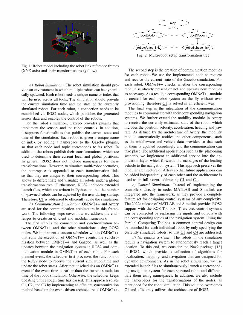
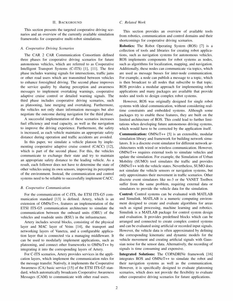
Fig. 1: Robot model including the robot link reference frames(XYZ-axis) and their transformations (yellow)
a) Robot Simulation: The robot simulation should pro-vide an environment in which multiple robots can be dynami-cally spawned. Each robot needs a unique name or index thatwill be used across all tools. The simulation should providethe current simulation time and the state of the currentlysimulated robots. For each robot, a connection needs to beestablished via ROS2 nodes, which publishes the generatedsensor data and enables the control of the robots.
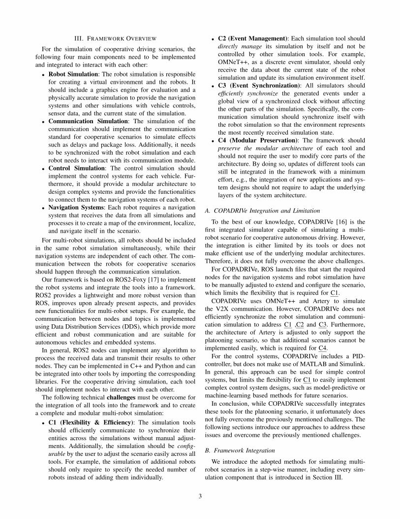
For the robot simulation, Gazebo provides plugins thatimplement the sensors and the robot controls. In addition,it supports functionalities that publish the current state andtime of the simulation. Each robot is given a unique nameor index by adding a namespace to the Gazebo plugins,so that each node and topic corresponds to its robot. Inaddition, the robots publish their transformations, which areused to determine their current local and global positions.In general, ROS2 does not include namespaces for thesetransformations. However, to simulate multi-robot scenarios,the namespace is appended to each transformation link,so that they are unique to their corresponding robot. Thisallows to differentiate and visualize all robots under a globaltransformation tree. Furthermore, ROS2 includes extendedlaunch files, which are written in Python, so that the numberof spawned robots can be adjusted by the user during startup.Therefore, C1 is addressed to efficiently scale the simulation.
b) Communication Simulation: OMNeT++ and Arteryare used for the communication architecture in this frame-work. The following steps cover how we address the chal-lenges to create an efficient and modular framework.
The first step is the connection and synchronization be-tween OMNeT++ and the other simulations using ROS2nodes. We implement a custom scheduler within OMNeT++that runs the execution of OMNeT++ events, the synchro-nization between OMNeT++ and Gazebo, as well as theupdates between the navigation system in ROS2 and com-munication module in OMNeT++ of each robot. For eachplanned event, the scheduler first processes the functions ofthe ROS2 node to receive the current simulation time andupdate the robot states. After that, it schedules an OMNeT++event if the event time is earlier than the current simulationtime of the robot simulation. Otherwise, the scheduler keepsupdating until enough time has passed. This approach solvesC1, C2, and C3 by implementing an efficient synchronizationmethod based on the event-driven architecture of OMNeT++.
Fig. 2: Multi-robot setup transformation tree
The second step is the creation of communication modulesfor each robot. We use the implemented node to requestand receive the current state of the Gazebo simulation. Foreach robot, OMNeT++ checks whether the correspondingmodule is already present or not and spawns new modulesas necessary. As a result, a corresponding OMNeT++ moduleis created for each robot system on the fly without overprovisioning, therefore C1 is solved in an efficient way.
The final step is the integration of the communicationmodules to communicate with their corresponding navigationsystems. We further extend the mobility module in Arteryto receive the currently estimated state of the robot, whichincludes the position, velocity, acceleration, heading and yawrate. As defined by the architecture of Artery, the mobilitymodule automatically notifies the other components, suchas the middleware and vehicle data provider, so that eachof them is updated accordingly and the communication cantake place. For additional applications such as the platooningscenario, we implement an additional service into the ap-plication layer, which forwards the messages of the leadingvehicle to the navigation system. This approach preserves themodular architecture of Artery so that future applications canbe added independently of each other and the architecture isused to its full extent, addressing C1 and C4.
c) Control Simulation: Instead of implementing thecontrollers directly in code, MATLAB and Simulink areintegrated into the framework, as they provide a completefeature set for designing control systems of any complexity.The 2022a release of MATLAB and Simulink provides ROS2support with the ROS Toolbox. Therefore, control systemscan be connected by replacing the inputs and outputs withthe corresponding topics of the navigation system. Using theParallel Computing Toolbox, a common control design canbe launched for each individual robot by only specifying thecurrently simulated robots, so that C1 and C4 are addressed.
d) Navigation Systems: The robots in the simulationrequire a navigation system to autonomously reach a targetlocation. To this end, we consider the Nav2 package [18]in ROS2, which provides a collection of algorithms forlocalization, mapping, and navigation that are designed fordynamic environments. As in the robot simulation, we useextended launch files to simultaneously launch a correspond-ing navigation system for each spawned robot and differen-tiate them using namespaces. In addition, we also includethe namespaces for the transformations of the nodes, asmentioned for the robot simulation. This solution overcomesC1 and efficiently utilizes the architecture of ROS2.
4
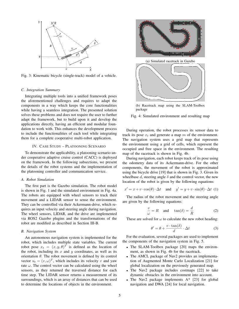
Fig. 3: Kinematic bicycle (single-track) model of a vehicle.
C. Integration Summary
Integrating multiple tools into a unified framework posesthe aforementioned challenges and requires to adapt thecomponents in a way which keeps the core functionalitieswhile having a seamless integration. The presented solutionsolves these problems and does not require the user to furtheradapt the framework, but to build upon it and develop theapplications directly, having an efficient and modular foun-dation to work with. This enhances the development processto include the functionalities of each tool while integratingthem for a complete cooperative multi-robot application.
IV. CASE STUDY – PLATOONING SCENARIO
To demonstrate the applicability, a platooning scenario un-der cooperative adaptive cruise control (CACC) is deployedon the framework. In the following subsections, we presentthe details of the robot systems and the implementation ofthe platooning controller and communication service.
A. Robot Simulation
The first part is the Gazebo simulation. The robot modelis shown in Fig. 1 and the simulated environment in Fig. 4a.The robots are equipped with wheel sensors to track theirmovement and a LIDAR sensor to sense the environment.They can be controlled via their Ackermann-drive, which re-quires an input velocity and steering angle during navigation.The wheel sensors, LIDAR, and the drive are implementedvia ROS2 Gazebo plugins and the transformations of therobot are modified as described in Section III-B.
B. Navigation System
An autonomous navigation system is implemented for therobot, which includes multiple state variables. The currentrobot pose xt = (x, y, θ)T is defined as the location ofthe robot, including its x and y coordinates, as well as itsorientation θ. The robot movement is defined by its controlvector ut = (v, ω)T , which includes its velocity v and yawrate ω. The control vector can be calculated using the wheelsensors, as they returned the traversed distance for eachtime step. The LIDAR sensor returns a measurement of itssurroundings, which is an array of distances that can be usedto determine the locations of objects in the environment.
(a) Simulated racetrack in Gazebo
(b) Racetrack map using the SLAM-Toolboxpackage
Fig. 4: Simulated environment and resulting map
During operation, the robot processes its sensor data totrack its pose xt and generate a map m of the environment.The navigation system uses a grid map that representsthe environment using a grid of cells, which represent theoccupied and free space in the environment. The resultingmap of the racetrack is shown in Fig. 4b.
During navigation, each robot keeps track of its pose usingthe odometry data of its Ackermann-drive. For the othercomponents, the movement of the robot is approximatedusing the bicycle drive [19] that is shown in Fig. 3. Given itswheelbase d, steering angle δ and the control vector, the newlocation of the robot is given by the following equations:
x′ = x+ v · cos(θ) ·∆t and y′ = y+ v · sin(θ) ·∆t (1)
The radius of the robot movement and the steering angleare given by the following equations:
v
ω= R and tan(δ) =
d
R(2)
These are solved for ω to calculate the new robot heading:
θ′ = θ +v · tan(δ)
d·∆t (3)
For the evaluation, several packages are used to implementthe components of the navigation system in Fig. 5.• The SLAM-Toolbox package [20] maps the environ-
ment, as shown in Fig. 4b for the racetrack.• The AMCL package of Nav2 provides an implementa-
tion of Augmented Monte Carlo Localization [21] forglobal localization on the previously generated map.
• The Nav2 package includes costmaps [22] to takedynamic obstacles in the environment into account.
• The Nav2 package implements A* [23] for globalnavigation and DWA [24] for local navigation.
5

Fig. 5: Robot navigation system overview
The resulting robot is capable of navigating itself indynamic environments and provides the other simulationswith the required data to communicate with other robots andimplement the control systems for the scenarios.
C. Communication Simulation
For each robot, a node is implemented such that it collectsand forwards the current state of the robot to Artery andOMNeT++, including the position, velocity, acceleration,heading and yaw rate. The communication for platooning isimplemented by adding a new platooning service to Artery.Through the already implemented CA basic service, thevehicles exchange CAMs that contain the information aboutthe other’s state. The platooning service of Vehicle i onlyconsiders the CAMs from its leading Vehicle i−1, for i ≥ 2and forwards them to the navigation system of the robot.Afterwards, the navigation system receives and processes thedata directly or through its control systems.
D. Control Simulation
For platooning, a controller is required to calculate theappropriate acceleration and yaw rate to maintain a stablesafety distance during operation. In this paper, the controllerdesigned in [12] is implemented in MATLAB and Simulinkand connected using the ROS and Parallel Computing Tool-box. For completeness, we sketch their controller here.
The controller is responsible for the longitudinal andlateral control implements a time-gap spacing policy witha standstill distance of ri meters and a time gap ofhi seconds. It is designed for non-zero positive velocitiesand takes the velocity and longitudinal and lateral accelera-tion into account. Furthermore, it avoids cutting corners byimplementing an extended look-ahead approach and featuresa time-gap spacing policy instead of a constant spacing.
For longitudinal control, it defines the error ei as thedifference between the real distance di and the desireddistance dr,i between the positions pi and pi−1:
ei = di − dr,i = (pi−1 − pi)− dr,i (4)
dr,i =
[drx,idry,i
]= (ri + hi · vi)
[cos θisin θi
](5)
However, using this error would lead to the vehicle cuttingcorners, as it always directly targets the desired position,without taking the leading vehicle’s heading into account.
The extended look-ahead approach in [12] fixes this issueby defining a new look-ahead point which includes theleading vehicle’s heading in the extension vector si−1. Itapplies the following error term for the case of ωi−1 6= 0:
ei = (pi−1 + si−1)− (pi + ri + hi · vi) (6)
The controller outputs consists of the acceleration and yawrate of a unicycle drive robot. It needs to be converted tothe corresponding output velocity and steering angle of theAckermann-drive. The kinematic model of a unicycle driveis described by the following equations:
xi = vi · cos(θi), yi = vi · sin(θi), (7)
vi = ai, θi = ωi (8)
The output velocity corresponds to the integral of theacceleration, which can be implemented using an Integratorin Simulink. Additionally, it is filtered to only return positivevalues and turned off in case the leading vehicle is standingstill or moves slower than a threshold value. Next, thefollowing equation is used to convert the yaw rate of therobot to the steering angle of the bicycle-drive model:
δ = atan
(ω · dv
)(9)
The controller in [12] is configured by four parameters,including the gains for longitudinal and lateral control aswell as the standstill distance and time-gap.
V. EVALUATION
Using the previously introduced robot system and theframework, the following aspects were evaluated:
• Compare an ideal channel that is implemented by aROS2 topic to the communication simulation via Arteryand the ETSI ITS-G5 architecture. Highlight the effectsof the communication on the received data.
• Compare the theoretical controller performance usingsynthetic input signals and approximated vehicles to thecontroller performance when used in the framework,which accurately simulates the robot movement andincludes the communication effects. This highlights thedifference between the performance using approxima-tions under ideal conditions and an accurate simulation.
Head-to-head comparisons between COPADRIVe and ourmodularly integrated simulation framework would be ableto demonstrate how much improvement we have achieved.However, it would require to port their robot simulationenvironment, navigation, and control systems to ROS2 andwould include the pitfalls of their integration pointed outin Section III-A. Therefore, the evaluation only showcasesscenarios that are simulated using our framework.
6
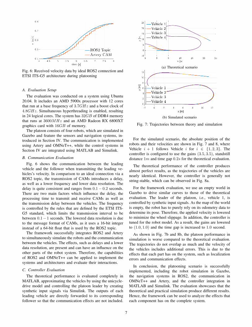
Fig. 6: Received velocity data by ideal ROS2 connection andETSI ITS-G5 architecture during platooning
A. Evaluation Setup
The evaluation was conducted on a system using Ubuntu20.04. It includes an AMD 5900x processor with 12 coresthat run at a base frequency of 3.7GHz and a boost clock of4.8GHz. Simultaneous hyperthreading is enabled, resultingin 24 logical cores. The system has 32GB of DDR4 memorythat runs at 3600MHz and an AMD Radeon RX 6800XTgraphics card with 16GB of memory.
The platoon consists of four robots, which are simulated inGazebo and feature the sensors and navigation systems, in-troduced in Section IV. The communication is implementedusing Artery and OMNeT++, while the control systems inSection IV are integrated using MATLAB and Simulink.
B. Communication Evaluation
Fig. 6 shows the communication between the leadingvehicle and the follower when transmitting the leading ve-hicles’s velocity. In comparison to an ideal connection via aROS2 topic, the transmission of CAMs introduces a delay,as well as a lower frequency and lower data resolution. Thedelay is quite consistent and ranges from 0.1− 0.2 seconds.There are two main factors which influence the delay, theprocessing time to transmit and receive CAMs as well asthe transmission delay between the vehicles. The frequencyis controlled by the rules that are defined by the ETSI ITS-G5 standard, which limits the transmission interval to bebetween 0.1−1 seconds. The lowered data resolution is dueto the message format of CAMs, as it uses a 16-bit integerinstead of a 64-bit float that is used by the ROS2 topic.
The framework successfully integrates ROS2 and Arteryto simultaneously simulate the robots and the communicationbetween the vehicles. The effects, such as delays and a lowerdata resolution, are present and can have an influence on theother parts of the robot system. Therefore, the capabilitiesof ROS2 and OMNeT++ can be applied to implement thesystems and architectures and evaluate their interactions.
C. Controller Evaluation
The theoretical performance is evaluated completely inMATLAB, approximating the vehicles by using the unicycle-drive model and controlling the platoon leader by creatingsynthetic input signals via Simulink. The outputs of eachleading vehicle are directly forwarded to its correspondingfollower so that the communication effects are not included.
(a) Theoretical scenario
(b) Simulated scenario
Fig. 7: Trajectories between theory and simulation
For the simulated scenario, the absolute position of therobots and their velocities are shown in Fig. 7 and 8, whereVehicle i + 1 follows Vehicle i for i ∈ {1, 2, 3}. Thecontroller is configured to use the gains (3.5, 3.5), standstilldistance 1m and time gap 0.2s for the theoretical evaluation.
The theoretical performance of the controller producesalmost perfect results, as the trajectories of the vehicles arenearly identical. However, the controller is generally notstring-stable, which can be observed in Fig. 8a.
For the framework evaluation, we use an empty world inGazebo to drive similar curves to those of the theoreticalevaluation. The leader of the platoon, i.e., vehicle 1, iscontrolled by synthetic input signals. As the map of the worldis empty, the robot has to purely rely on its odometry data todetermine its pose. Therefore, the applied velocity is loweredto minimize the wheel slippage. In addition, the controller istuned for the robot model. As a result, the gains are loweredto (1.0, 1.0) and the time gap is increased to 1.0 second.
As shown in Fig. 7b and 8b, the platoon performance insimulation is worse compared to the theoretical evaluation.The trajectories do not overlap as much and the velocity ofthe vehicles includes additional errors. This is due to theeffects that each part has on the system, such as localizationerrors and communication effects.
In conclusion, the platooning scenario is successfullyimplemented, including the robot simulation in Gazebo,the navigation systems in ROS2, the communication inOMNeT++ and Artery, and the controller integration inMATLAB and Simulink. The evaluation showcases that thetheoretical and practical simulation produce different results.Hence, the framework can be used to analyze the effects thateach component has on the complete system.
7
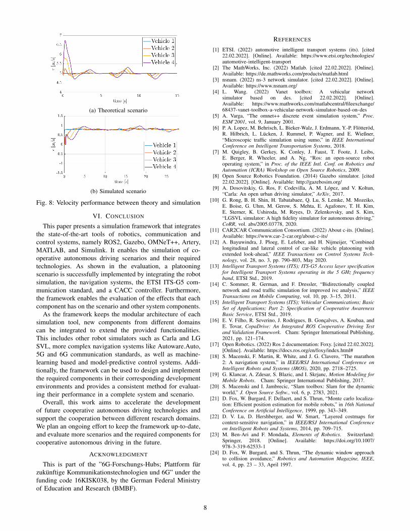
(a) Theoretical scenario
(b) Simulated scenario
Fig. 8: Velocity performance between theory and simulation
VI. CONCLUSION
This paper presents a simulation framework that integratesthe state-of-the-art tools of robotics, communication andcontrol systems, namely ROS2, Gazebo, OMNeT++, Artery,MATLAB, and Simulink. It enables the simulation of co-operative autonomous driving scenarios and their requiredtechnologies. As shown in the evaluation, a platooningscenario is successfully implemented by integrating the robotsimulation, the navigation systems, the ETSI ITS-G5 com-munication standard, and a CACC controller. Furthermore,the framework enables the evaluation of the effects that eachcomponent has on the scenario and other system components.
As the framework keeps the modular architecture of eachsimulation tool, new components from different domainscan be integrated to extend the provided functionalities.This includes other robot simulators such as Carla and LGSVL, more complex navigation systems like Autoware.Auto,5G and 6G communication standards, as well as machine-learning based and model-predictive control systems. Addi-tionally, the framework can be used to design and implementthe required components in their corresponding developmentenvironments and provides a consistent method for evaluat-ing their performance in a complete system and scenario.
Overall, this work aims to accelerate the developmentof future cooperative autonomous driving technologies andsupport the cooperation between different research domains.We plan an ongoing effort to keep the framework up-to-date,and evaluate more scenarios and the required components forcooperative autonomous driving in the future.
ACKNOWLEDGMENT
This is part of the ”6G-Forschungs-Hubs; Plattform furzukunftige Kommunikationstechnologien und 6G” under thefunding code 16KISK038, by the German Federal Ministryof Education and Research (BMBF).
REFERENCES
[1] ETSI. (2022) automotive intelligent transport systems (its). [cited22.02.2022]. [Online]. Available: https://www.etsi.org/technologies/automotive-intelligent-transport
[2] The MathWorks, Inc. (2022) Matlab. [cited 22.02.2022]. [Online].Available: https://de.mathworks.com/products/matlab.html
[3] nsnam. (2022) ns-3 network simulator. [cited 22.02.2022]. [Online].Available: https://www.nsnam.org/
[4] L. Wang. (2022) Vanet toolbox: A vehicular networksimulator based on des. [cited 22.02.2022]. [Online].Available: https://www.mathworks.com/matlabcentral/fileexchange/68437-vanet-toolbox-a-vehicular-network-simulator-based-on-des
[5] A. Varga, “The omnet++ discrete event simulation system,” Proc.ESM’2001, vol. 9, January 2001.
[6] P. A. Lopez, M. Behrisch, L. Bieker-Walz, J. Erdmann, Y.-P. Flotterod,R. Hilbrich, L. Lucken, J. Rummel, P. Wagner, and E. Wießner,“Microscopic traffic simulation using sumo,” in IEEE InternationalConference on Intelligent Transportation Systems, 2018.
[7] M. Quigley, B. Gerkey, K. Conley, J. Faust, T. Foote, J. Leibs,E. Berger, R. Wheeler, and A. Ng, “Ros: an open-source robotoperating system,” in Proc. of the IEEE Intl. Conf. on Robotics andAutomation (ICRA) Workshop on Open Source Robotics, 2009.
[8] Open Source Robotics Foundation. (2014) Gazebo simulator. [cited22.02.2022]. [Online]. Available: http://gazebosim.org/
[9] A. Dosovitskiy, G. Ros, F. Codevilla, A. M. Lopez, and V. Koltun,“Carla: An open urban driving simulator,” ArXiv, 2017.
[10] G. Rong, B. H. Shin, H. Tabatabaee, Q. Lu, S. Lemke, M. Mozeiko,E. Boise, G. Uhm, M. Gerow, S. Mehta, E. Agafonov, T. H. Kim,E. Sterner, K. Ushiroda, M. Reyes, D. Zelenkovsky, and S. Kim,“LGSVL simulator: A high fidelity simulator for autonomous driving,”CoRR, vol. abs/2005.03778, 2020.
[11] CAR2CAR Communication Consortium. (2022) About c-its. [Online].Available: https://www.car-2-car.org/about-c-its/
[12] A. Bayuwindra, J. Ploeg, E. Lefeber, and H. Nijmeijer, “Combinedlongitudinal and lateral control of car-like vehicle platooning withextended look-ahead,” IEEE Transactions on Control Systems Tech-nology, vol. 28, no. 3, pp. 790–803, May 2020.
[13] Intelligent Transport Systems (ITS); ITS-G5 Access layer specificationfor Intelligent Transport Systems operating in the 5 GHz frequencyband, ETSI Std., 2019.
[14] C. Sommer, R. German, and F. Dressler, “Bidirectionally couplednetwork and road traffic simulation for improved ivc analysis,” IEEETransactions on Mobile Computing, vol. 10, pp. 3–15, 2011.
[15] Intelligent Transport Systems (ITS); Vehicular Communications; BasicSet of Applications; Part 2: Specification of Cooperative AwarenessBasic Service, ETSI Std., 2019.
[16] E. V. Filho, R. Severino, J. Rodrigues, B. Goncalves, A. Koubaa, andE. Tovar, CopaDrive: An Integrated ROS Cooperative Driving Testand Validation Framework. Cham: Springer International Publishing,2021, pp. 121–174.
[17] Open Robotics. (2022) Ros 2 documentation: Foxy. [cited 22.02.2022].[Online]. Available: https://docs.ros.org/en/foxy/index.html#
[18] S. Macenski, F. Martin, R. White, and J. G. Clavero, “The marathon2: A navigation system,” in IEEE/RSJ International Conference onIntelligent Robots and Systems (IROS), 2020, pp. 2718–2725.
[19] G. Klancar, A. Zdesar, S. Blazic, and I. Skrjanc, Motion Modeling forMobile Robots. Cham: Springer International Publishing, 2017.
[20] S. Macenski and I. Jambrecic, “Slam toolbox: Slam for the dynamicworld,” J. Open Source Softw., vol. 6, p. 2783, 2021.
[21] D. Fox, W. Burgard, F. Dellaert, and S. Thrun, “Monte carlo localiza-tion: Efficient position estimation for mobile robots,” in 16th NationalConference on Artificial Intelligence, 1999, pp. 343–349.
[22] D. V. Lu, D. Hershberger, and W. Smart, “Layered costmaps forcontext-sensitive navigation,” in IEEE/RSJ International Conferenceon Intelligent Robots and Systems, 2014, pp. 709–715.
[23] M. Ben-Ari and F. Mondada, Elements of Robotics. Switzerland:Springer, 2018. [Online]. Available: https://doi.org/10.1007/978-3-319-62533-1
[24] D. Fox, W. Burgard, and S. Thrun, “The dynamic window approachto collision avoidance,” Robotics and Automation Magazine, IEEE,vol. 4, pp. 23 – 33, April 1997.
8