Modelling of stresses and strains in bonded concrete overlays subjected to differential volume...
7
Modelling of stresses and strains in bonded concrete overlays subjected to differential volume changes Jian Zhou a, * , Guang Ye a,b , Erik Schlangen a , Klaas van Breugel a a Microlab, Faculty of Civil Engineering and Geosciences, Delft University of Technology, P.O. Box 5048, 2600 GA, Delft, The Netherlands b Magnel Laboratory for Concrete Research, Department of Structural Engineering, Ghent University, Ghent, Belgium Available online 14 December 2007 Abstract The differential volume changes between repair material and substrate concrete induces stresses in concrete overlays. These stresses could cause the repair material cracking or the interface delamination, which facilitate the penetration of harmful substances into con- crete and hence accelerate the deterioration of concrete overlays. In order to investigate the characteristics of these stresses, an analytical model has been developed based on the plate theory and the assumption of the linear relation between shear stress and slip at the inter- face. This model is able to calculate the tensile stress in the repair material, shear and normal stresses at the interface and the correspond- ing strains. With this model, the influence of the interface shear stiffness, the dimension of the concrete overlay, and the elastic moduli of two materials on stresses and strains was studied. Ó 2007 Elsevier Ltd. All rights reserved. Keywords: Analytical model; Bonded concrete overlay; Stress and strain; Differential volume changes 1. Introduction Concrete overlay is widely used to repair or strengthen concrete structures, such as pavements, industrial floors and bridge decks. It consists of replacing the damaged con- crete or increasing the cross section of existing concrete structures with the repair material, which is fully bonded on the substrate concrete. However, the concrete overlay experiences a serious performance problem. Although many researches have been carried out to enhance the durability of the concrete overlay, failures were often observed. The failure of concrete overlays was mainly attributed to the high stresses induced by the differential volume changes between repair material and substrate con- crete [1]. Most repair materials have a tendency to contract due to thermal and moisture movements especially at the early stage, while the volume change of substrate concrete is almost complete. The shrinkage of repair material is therefore restrained by the substrate concrete through the interface. As a result, the tensile stress is induced in the repair material and the shear as well as normal stresses are induced at the interface. Once the tensile stress exceeds the tensile strength of the repair material or the stresses at the interface exceed the bond strength, these stresses lead to the repair material cracking or the interface delamina- tion respectively. In the concrete overlay with a large differ- ential shrinkage, the cracks can propagate through the whole depth of the repair material and the interface delam- ination can cause the peeling of the repair material from the substrate concrete. Moreover, the repair material cracking and the interface delamination accelerate the pen- etration of water, oxygen, chlorides, alkalis or sulphates into the concrete overlay. This causes reinforcement corro- sion or concrete deterioration. Finally, the concrete repair fails and the repair of concrete repair must be carried out again. There are several parameters, which have influence on the characteristics of the stresses and strains in the concrete overlay subjected to differential volume changes. For a cer- tain repair system, the stresses induced by the differential shrinkage are proportional to the value of this shrinkage 0167-8442/$ - see front matter Ó 2007 Elsevier Ltd. All rights reserved. doi:10.1016/j.tafmec.2007.11.006 * Corresponding author. Tel.: +31 15 278001; fax: +31 15 2786383. E-mail address: [email protected] (J. Zhou). www.elsevier.com/locate/tafmec Available online at www.sciencedirect.com Theoretical and Applied Fracture Mechanics 49 (2008) 199–205
-
Upload
independent -
Category
Documents
-
view
2 -
download
0
Transcript of Modelling of stresses and strains in bonded concrete overlays subjected to differential volume...
Available online at www.sciencedirect.com
www.elsevier.com/locate/tafmec
Theoretical and Applied Fracture Mechanics 49 (2008) 199–205
Modelling of stresses and strains in bonded concrete overlayssubjected to differential volume changes
Jian Zhou a,*, Guang Ye a,b, Erik Schlangen a, Klaas van Breugel a
a Microlab, Faculty of Civil Engineering and Geosciences, Delft University of Technology, P.O. Box 5048, 2600 GA, Delft, The Netherlandsb Magnel Laboratory for Concrete Research, Department of Structural Engineering, Ghent University, Ghent, Belgium
Available online 14 December 2007
Abstract
The differential volume changes between repair material and substrate concrete induces stresses in concrete overlays. These stressescould cause the repair material cracking or the interface delamination, which facilitate the penetration of harmful substances into con-crete and hence accelerate the deterioration of concrete overlays. In order to investigate the characteristics of these stresses, an analyticalmodel has been developed based on the plate theory and the assumption of the linear relation between shear stress and slip at the inter-face. This model is able to calculate the tensile stress in the repair material, shear and normal stresses at the interface and the correspond-ing strains. With this model, the influence of the interface shear stiffness, the dimension of the concrete overlay, and the elastic moduli oftwo materials on stresses and strains was studied.� 2007 Elsevier Ltd. All rights reserved.
Keywords: Analytical model; Bonded concrete overlay; Stress and strain; Differential volume changes
1. Introduction
Concrete overlay is widely used to repair or strengthenconcrete structures, such as pavements, industrial floorsand bridge decks. It consists of replacing the damaged con-crete or increasing the cross section of existing concretestructures with the repair material, which is fully bondedon the substrate concrete. However, the concrete overlayexperiences a serious performance problem. Althoughmany researches have been carried out to enhance thedurability of the concrete overlay, failures were oftenobserved. The failure of concrete overlays was mainlyattributed to the high stresses induced by the differentialvolume changes between repair material and substrate con-crete [1]. Most repair materials have a tendency to contractdue to thermal and moisture movements especially at theearly stage, while the volume change of substrate concreteis almost complete. The shrinkage of repair material istherefore restrained by the substrate concrete through the
0167-8442/$ - see front matter � 2007 Elsevier Ltd. All rights reserved.
doi:10.1016/j.tafmec.2007.11.006
* Corresponding author. Tel.: +31 15 278001; fax: +31 15 2786383.E-mail address: [email protected] (J. Zhou).
interface. As a result, the tensile stress is induced in therepair material and the shear as well as normal stressesare induced at the interface. Once the tensile stress exceedsthe tensile strength of the repair material or the stresses atthe interface exceed the bond strength, these stresses leadto the repair material cracking or the interface delamina-tion respectively. In the concrete overlay with a large differ-ential shrinkage, the cracks can propagate through thewhole depth of the repair material and the interface delam-ination can cause the peeling of the repair material fromthe substrate concrete. Moreover, the repair materialcracking and the interface delamination accelerate the pen-etration of water, oxygen, chlorides, alkalis or sulphatesinto the concrete overlay. This causes reinforcement corro-sion or concrete deterioration. Finally, the concrete repairfails and the repair of concrete repair must be carried outagain.
There are several parameters, which have influence onthe characteristics of the stresses and strains in the concreteoverlay subjected to differential volume changes. For a cer-tain repair system, the stresses induced by the differentialshrinkage are proportional to the value of this shrinkage
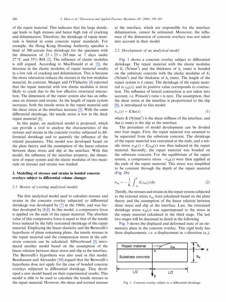
Fig. 1. Concrete overlay subject to a differential shrinkage.
200 J. Zhou et al. / Theoretical and Applied Fracture Mechanics 49 (2008) 199–205
of the repair material. This indicates that the large shrink-age leads to high stresses and hence high risk of crackingand delamination. Therefore, the shrinkage of repair mate-rials is limited in some concrete repair standards. Forexample, the Hong Kong Housing Authority specifies alimit of 300 lstrain free shrinkage for the specimen withthe dimension of 25 � 25 � 285 mm at 7 days under27 �C and 55% RH [2]. The influence of elastic modulusis still argued. According to MacDonald et al. [3], thedecrease in the elastic modulus of repair material resultsin a low risk of cracking and delamination. This is becausethe stress relaxation reduces the stresses in the low modulusmaterial. In contrast, Manget and O’Flaherity [4] reportedthat the repair material with low elastic modulus is morelikely to crack due to the low effective structural interac-tion. The dimension of the repair system also has an influ-ence on stresses and strains. As the length of repair systemincreases, both the tensile stress in the repair material andthe shear stress at the interface increase [5]. With the samedifferential shrinkage, the tensile stress is low in the thickrepair material [6].
In this paper, an analytical model is proposed, whichcan provide a tool to analyse the characteristics of thestresses and strains in the concrete overlay subjected to dif-ferential shrinkage and to quantify the influence of therelated parameters. This model was developed based onthe plate theory and the assumption of the linear relationbetween shear stress and slip at the interface. With thismodel, the influence of the interface property, the dimen-sion of repair system and the elastic modulus of two mate-rials on stresses and strains was studied.
2. Modelling of stresses and strains in bonded concrete
overlays subject to differential volume changes
2.1. Review of existing analytical models
The first analytical model used to calculate stresses andstrains in the concrete overlay subjected to differentialshrinkage was developed by [7] in the 1960s, and was fur-ther developed by [8,9]. In this model, a compressive forceis applied on the ends of the repair material. The absolutevalue of this compressive force is equal to that of the tensileforce induced by the fully restrained shrinkage of the repairmaterial. Employing the linear elasticity and the Bernoulli’shypothesis of plane remaining plane, the tensile stresses inthe repair material and the compression stress in the sub-strate concrete can be calculated. Silfwerbrand [5] intro-duced another model based on the assumption of thelinear relation between shear stress and slip at the interface.The Bernoulli’s hypothesis was also used in this model.Beushausen and Alexander [10] argued that the Bernoulli’shypothesis dose not apply for the case of bonded concreteoverlays subjected to differential shrinkage. They devel-oped a new model based on their experimental results. Thismodel is able to be used to calculate the tensile stresses inthe repair material. However, the shear and normal stresses
at the interface, which are responsible for the interfacedelamination, cannot be estimated. Moreover, the influ-ence of the dimension of concrete overlays was not takeninto account in their model.
2.2. Development of an analytical model
Fig. 1 shows a concrete overlay subject to differentialshrinkage. The repair material with the elastic modulusof Er (N/mm2) and the thickness of hr (mm) is bondedon the substrate concrete with the elastic modulus of Es
(N/mm2) and the thickness of hs (mm). The length of therepair system is L (mm). The shrinkage of the repair mate-rial is esh(y), and its positive value corresponds to contrac-tion. The influence of lateral contraction is not taken intoaccount, i.e. Poisson’s ratio t is zero. The assumption, thatthe shear stress at the interface is proportional to the slip[9], is introduced to this model:
rxyðxÞ ¼ KDuðxÞ ð1Þ
where K (N/mm3) is the shear stiffness of the interface, andDu(x) (mm) is the slip at the interface.
The procedure of model development can be dividedinto four stages. First, the repair material was assumed tobe separated from the substrate concrete. The shrinkageof the repair material was restrained at the ends, and a ten-sile stress rsh(y) = Eresh(y) was thus induced in the repairmaterial. Secondly, the repair material was bonded onthe substrate concrete. For the equilibrium of the repairsystem, a compressive stress �rsh(y) were then applied atthe ends of the repair material. This stress was simplifiedto be constant through the depth of the repair material(Fig. 2b):
req ¼ �1
hr
Z 0
�hr
EreshðyÞdy ð2Þ
Thirdly, the stresses and strains in the repair system subjectedto the external stress req were calculated based on the platetheory and the assumption of the linear relation betweenshear stress and slip at the interface. Last, the restrainedshrinkage stress rsh(y) was superimposed to the stress inthe repair material calculated in the third stage. The lasttwo stages will be discussed in detail in the following.
Fig. 3 shows the displaced and deformed state of an ele-mentary plate in the concrete overlay. This rigid body hasthree displacements, i.e. a displacement in x-direction (ux),

Fig. 4. Equilibrium of an elementary plate.
Fig. 3. Displaced and deformed state of an elementary plate.
Fig. 2. Modelling stresses induced by differential shrinkage.
J. Zhou et al. / Theoretical and Applied Fracture Mechanics 49 (2008) 199–205 201
a displacement in y-direction (uy), and a rotation (xxy), andthree deformations, i.e. a strain in x-direction (exx), a strainin y-direction (eyy), and a shear deformation (cxy). Thekinematic equations relating the displacements and thedeformations can be written as
exx ¼oux
oxð3aÞ
eyy ¼ouy
oyð3bÞ
cxy ¼oux
oyþ ouy
oxð3cÞ
According to Hooke’s law, the constitutive equations,which describe the relations between the stresses and thestrains, can be given:
exx ¼1
Erxx ð4aÞ
eyy ¼1
Eryy ð4bÞ
cxy ¼2
Erxy ð4cÞ
where rxx, ryy, and rxy are the stress in x-direction, thestress in y-direction, and the shear stress respectively.Based on the equilibrium of this elementary plate(Fig. 4), the equilibrium equations, which relate the loadsto the stress resultants, can be obtained:
orxx
oxþ orxy
oy¼ 0 ð5aÞ
oryy
oyþ orxy
ox¼ 0 ð5bÞ
By combining the kinematic equations, the constitutiveequations, and the equilibrium equations, three partial dif-ferential equations are derived:
Eo4ux
ox4þ 2
o4ux
ox2y2þ o4ux
oy4
� �¼ 0 ð6aÞ
Eo
4uy
ox4þ 2
o4uy
ox2y2þ o
4uy
oy4
� �¼ 0 ð6bÞ
o2ux
ox2þ 1
2
o2ux
oy2þ 1
2
o2uy
oxoy¼ 0 ð6cÞ
With supposing the solution in the form of ux = Aekx+ky,the general solutions are solved:
ux ¼ ðA1ðekx � e�kxÞ þ A2xðekx
þ e�kxÞÞ sinðky þ A3Þ þ A4x ð7aÞ
uy ¼A1kþ 3A2
kðekx þ e�kxÞ þ A2xðekx � e�kxÞ
� �� cosðky þ A3Þ þ A5y ð7bÞ
where Ai are the constants. To determine these constants,the following boundary conditions are needed:
1. The ends of the repair material are subject to the com-pression stresses req, i.e. when x ¼ � L
2; rr
xx ¼ req.2. The ends of the substrate concrete are free, i.e. when
x ¼ � L2; rs
xx ¼ 0.3. The top of the repair material is not subject to any load,
i.e. when y = �hr, rrxy ¼ 0 and rr
yy ¼ 0.4. The bottom of the substrate concrete is free in x-direc-
tion, but can not bend, i.e. when y ¼ hs; rsxy ¼ 0 and
usy ¼ 0.
5. At the interface the normal stresses in the repair materialare equal to those in the substrate concrete, and theirsum is equal to zero, i.e. when y = 0, rr
yy ¼ rsyy andR L
2
�L2rr
yy dx ¼ 0.
202 J. Zhou et al. / Theoretical and Applied Fracture Mechanics 49 (2008) 199–205
6. At the interface the shear stresses in the repair materialand in the substrate concrete are equal, and are propor-tional to the slip, i.e. when y = 0, rr
xy ¼ rsxy ¼ Kðus
x � urxÞ.
Where ur, rr, us, and rs are the displacements and the stres-ses in the repair material and in the substrate concreterespectively. By superimposing rsh(y) in the repair material,the stresses and the strains in this concrete overlay aredetermined:
where k ¼ K cosðkhrÞEr sinðkhrÞ þ
K cosðkhsÞEs sinðkhsÞ.
rrxx ¼ Ere
rxx ¼ req
Es sinðkhsÞðekx þ e�kxÞ cosðky þ khrÞ þ Er sinðkhrÞðekL2 þ e�
kL2 Þ
ðEr sinðkhrÞ þ Es sinðkhsÞÞðekL2 þ e�
kL2 Þ
þ Eresh ð8aÞ
rryy ¼ Ere
ryy ¼
reqEs cosðkhsÞððekx þ e�kxÞ sinðky þ khrÞ � 2kL sinðkhrÞðe
kL2 � e�
kL2 ÞÞ
ðEr sinðkhrÞ � Es cosðkhsÞÞðekL2 þ e�
kL2 Þ
ð8bÞ
rrxy ¼ Ere
rxy ¼ �
reqEs sinðkhsÞðekx � e�kxÞ sinðky þ khrÞðEr sinðkhrÞ þ Es sinðkhsÞÞðe
kL2 þ e�
kL2 Þ
ð8cÞ
rsxx ¼ Ese
sxx ¼ �
reqEs sinðkhrÞððekx þ e�kxÞ cosðky � khsÞ � ðekL2 þ e�
kL2 ÞÞ
ðEr sinðkhrÞ þ Es sinðkhsÞÞðekL2 þ e�
kL2 Þ
ð8dÞ
rsyy ¼ Ese
syy ¼
reqEs sinðkhrÞððekx þ e�kxÞ cosðky � khsÞ � 2kL cosðkhsÞðe
kL2 � e�
kL2 ÞÞ
ðEr sinðkhrÞ � Es cosðkhsÞÞðekL2 þ e�
kL2 Þ
ð8eÞ
rsxy ¼ Ese
sxy ¼
reqEs sinðkhrÞðekx � e�kxÞ sinðky � khsÞðEr sinðkhrÞ þ Es sinðkhsÞÞðe
kL2 þ e�
kL2 Þ
ð8fÞ
-2
0
2
4
6
-1000 -500 0 500 1000Distance x (mm)
Str
ess
(MP
a)
xx in the repair material calculated by the analytical
model or FEMMASSE
yy at the interface calculated by the analytical model
xy at the interface calculated by the analytical model or FEMMASSE
yy at the interface calculated by FEMMASSE
σ
σσ
σ
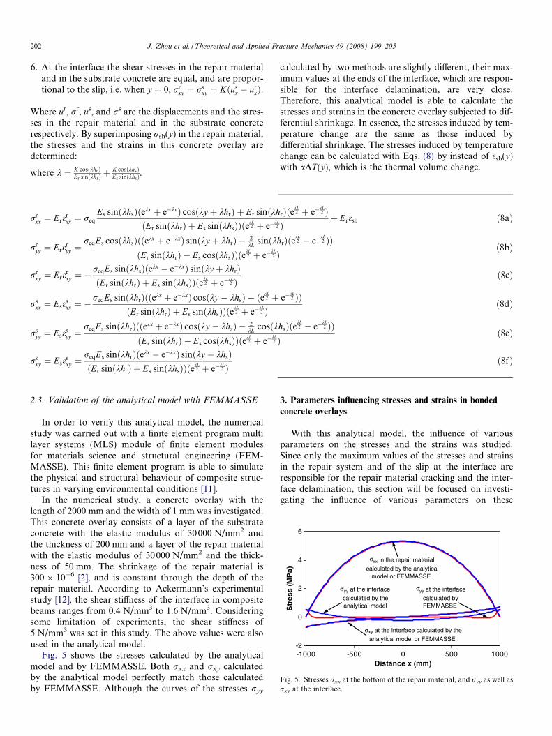
Fig. 5. Stresses rxx at the bottom of the repair material, and ryy as well asrxy at the interface.
2.3. Validation of the analytical model with FEMMASSE
In order to verify this analytical model, the numericalstudy was carried out with a finite element program multilayer systems (MLS) module of finite element modulesfor materials science and structural engineering (FEM-MASSE). This finite element program is able to simulatethe physical and structural behaviour of composite struc-tures in varying environmental conditions [11].
In the numerical study, a concrete overlay with thelength of 2000 mm and the width of 1 mm was investigated.This concrete overlay consists of a layer of the substrateconcrete with the elastic modulus of 30000 N/mm2 andthe thickness of 200 mm and a layer of the repair materialwith the elastic modulus of 30000 N/mm2 and the thick-ness of 50 mm. The shrinkage of the repair material is300 � 10�6 [2], and is constant through the depth of therepair material. According to Ackermann’s experimentalstudy [12], the shear stiffness of the interface in compositebeams ranges from 0.4 N/mm3 to 1.6 N/mm3. Consideringsome limitation of experiments, the shear stiffness of5 N/mm3 was set in this study. The above values were alsoused in the analytical model.
Fig. 5 shows the stresses calculated by the analyticalmodel and by FEMMASSE. Both rxx and rxy calculatedby the analytical model perfectly match those calculatedby FEMMASSE. Although the curves of the stresses ryy
calculated by two methods are slightly different, their max-imum values at the ends of the interface, which are respon-sible for the interface delamination, are very close.Therefore, this analytical model is able to calculate thestresses and strains in the concrete overlay subjected to dif-ferential shrinkage. In essence, the stresses induced by tem-perature change are the same as those induced bydifferential shrinkage. The stresses induced by temperaturechange can be calculated with Eqs. (8) by instead of esh(y)with aDT(y), which is the thermal volume change.
3. Parameters influencing stresses and strains in bondedconcrete overlays
With this analytical model, the influence of variousparameters on the stresses and the strains was studied.Since only the maximum values of the stresses and strainsin the repair system and of the slip at the interface areresponsible for the repair material cracking and the inter-face delamination, this section will be focused on investi-gating the influence of various parameters on these

0
0.1
0.2
0.3
0 2 4 6 8 10 12
Shear stiffness (N/mm3)
Slip
(mm
)
Fig. 7. Maximum values of the slip at the interface.
J. Zhou et al. / Theoretical and Applied Fracture Mechanics 49 (2008) 199–205 203
maximum values. The concrete overlay mentioned in Sec-tion 2.3 also was used in this section as the reference.According to Eqs. (8), the highest rxx in the repair materialis situated at the middle of the bottom, and the highest ryy
and rxy at the interface are situated at the two ends. Thesemaximum values can be calculated in the following:
rrxx;max ¼ Ere
rxx;max ¼
eshErðekL2 þ e�kL
2 � 2Þ1þ Er sin khr
Es sin khs
� �ekL
2 þ e�kL2
� � ð9aÞ
rinyy;max ¼
eshErEs sin khr cos khs
kðEs cos khs � Er sin khrÞk� ekL
2 � e�kL2
ekL2 þ e�kL
2
2
L
!ð9bÞ
rinxy;max ¼ KDu ¼
eshErEs sin khr sin khs ekL2 � e�kL
2
� �ðEs sin khs þ Er sin khrÞ ekL
2 þ e�kL2
� � ð9cÞ
3.1. Shear stiffness
Fig. 6 shows the influence of the shear stiffness of theinterface on the maximum values of the stresses. Theincreasing shear stiffness results in a higher rxx and thusa higher potential of cracking. This explains why the crack-ing is more serious in the concrete overlay with the rougherinterface, which has large shear stiffness [13]. When theshear stiffness goes infinite large, rxx approaches the high-est value of 7.2 N/mm2, which is equal to the stress calcu-lated by the Birkeland’s model [7]:
rrxx ¼
Eresh
1þ Eshs
Erhr
ð10Þ
This means that the Birkeland’s model overestimates thetensile stress in the repair material especially when the shearstiffness is low. As shown in Figs. 6 and 7, as the shear stiff-ness increases, ryy andrxy increase, while the slip decreases.This indicates that too large shear stiffness can result in highstresses at the interface, and too low shear stiffness can re-sult in a large slip. Both of them have negative influenceon the performance of the interface. Therefore, the concept,that the rougher the interface, the better the performance ofthe concrete overlay, is not correct.
0
2
4
6
8
0 2 4 6 8 10 12
Shear stiffness (N/mm3)
Str
ess
(MP
a)
xx
xyyy
σ
σ
Fig. 6. Maximum values of rxx in the repair material, and ryy and rxy atthe interface.
3.2. Dimension
Fig. 8 shows the influence of the length of the concreteoverlay. The stresses increase fast as the length increasesup to 4000 mm. Then they increase slightly, and rxx
approaches the highest value of 7.2 N/mm2. This meansthat the shrinkage of the repair material is restrained atthe interface within a critical length. When the length ofrepair system is higher than this critical length, it is notthe crucial factor any more. The value of the critical lengthis influenced by the shear stiffness. When the shear stiffnessis large, the shear stresses are high, rxx increases fast, andthus the critical length becomes small.
The influence of the ratio of the thickness of the repairmaterial to that of the substrate concrete is plotted inFig. 9. As the thickness ratio increases, the maximum valueof rxx decreases and the maximum values of ryy and rxy
increase. This indicates that the thinner repair material ismore likely to crack, while the risk of the interface dela-mination is higher in the concrete overlay with a thickerrepair material.
The dimension of most concrete overlays is determinedaccording to the loading capacity of the repair structuresand the dimension of original structures. However, thisanalytical model can be used to improve the performance
0
2
4
6
8
0 2000 4000 6000 8000 10000 12000Length (mm)
Str
ess
(MP
a) xx
yyxy
σ
σ σ
Fig. 8. Maximum values of rxx in the repair material, and ryy and rxy atthe interface.

0
2
4
6
8
0.4 0.6 0.8 1 1.2 1.4 1.6Elastic modulus ratio Er/Es
Str
ess
(MP
a)
xx
yy
xy
σ
σ
σ
Fig. 10. Maximum values of rxx in the repair material, and ryy and rxy atthe interface.
0
0.2
0.4
0.6
0.8
1
0.4 0.6 0.8 1 1.2 1.4 1.6
Elastic modulus ratio Er/Es
No
rnal
ized
str
ain
x/
sh
εε
Fig. 11. Maximum values of exx in the repair material.
0
2
4
6
8
0 0.2 0.4 0.6 0.8 1 1.2Thickness ratio hr/hs
Str
ess
(MP
a) xx
yy
xy
σ
σ
σ
Fig. 9. Maximum values of rxx in the repair material, and ryy and rxy atthe interface.
204 J. Zhou et al. / Theoretical and Applied Fracture Mechanics 49 (2008) 199–205
of repair works by changing other parameters. For exam-ple, in the concrete overlay with a long and thin repairmaterial the potential of repair material cracking can bereduced by smoothing the interface.
3.3. Elastic modulus
The influence of the ratio of the elastic modulus of therepair material to that of the substrate concrete is plotted
in Figs. 10 and 11. The increase in the ratio of the elasticmoduli causes a small increase in the maximum values ofryy and rxy and hence an increase in the risk of the inter-face delamination. As the ratio of the elastic moduliincreases, the maximum value of rxx increases, and themaximum value of exx decreases. Since the cracking is gov-erned by the ultimate strain, it can be expected that therepair material with smaller elastic modulus is more likelyto crack due to differential shrinkage. This coincides withMangat and Flaherty’s conclusion [4].
4. Conclusions and future work
An analytical model was developed based on the platetheory and the assumption of the linear relation betweenshear stress and slip at the interface. This model canbe used to calculate the tensile stress in the repair mate-rial and shear and normal stresses at the interfaceinduced by differential volume changes, which are respon-sible for the repair material cracking and the interfacedelamination. With this analytical model, the influenceof several parameters on stresses and strains wasstudied:
1. The high interface shear stiffness results in the increasein the stresses in the repair material and at the interfacebut the decrease in the slip at the interface.
2. The stresses in the repair material and at the interfaceare higher in the concrete overlay with a longer repairmaterial. These stresses approach to constant when thelength is higher than the critical value. The thick repairmaterial results in a low tensile stress in the repair mate-rial and high shear and debonding stresses at theinterface.
3. The repair material with higher elastic modulus has abetter resistance to cracking and leads to higher stressesat the interface.
In the future, a material model will be developed toinvestigate the thermal properties, shrinkage, and creepof various repair materials. By combining this model andthe analytical model, the characteristics of stresses andstrains in concrete overlays subject to differential volumechanges as elapsed time can be predicted. Experimentalstudy will be carried out to verify these models. Since fewexperimental results of the interface shear stiffness areavailable until now, tests will be performed to measurethe interface shear stiffness of concrete overlays with differ-ent repair materials and different surface preparationtechniques.
Acknowledgement
This research is financially supported by Delft Clusterand Heijmans Infrastructure B.V. They are gratefullyacknowledged.

J. Zhou et al. / Theoretical and Applied Fracture Mechanics 49 (2008) 199–205 205
References
[1] J. Bijen, T. Salet, Adherence of young concrete to old concrete —development of tools for engineering, in: Proceedings of the 2ndBolomey Workshop. Sion/Sitten, Switzerland, April, 1993, pp. 1–24.
[2] Hong Kong Housing Authority, Practice Notes for Concrete Repair,1991.
[3] J.E. McDonald, A.M. Vaysburd, P.H. Emmons, R.W. Poston, K.E.Kesner, Selecting durable repair materials: performance criteria-summary, Concr. Int. 24 (2002) 37–44.
[4] P.S. Mangat, F.J. O’Flaherty, Influence of elastic modulus on stressredistribution and cracking in repair patches, Cem. Concr. Res. 30(2000) 125–136.
[5] J. Silfwerbrand, Stresses and strains in composite concrete beamssubjected to differential shrinkage, ACI Struct. J. 94 (1997) 347–353.
[6] H. Beushausen, Long-term Performance of Bonded Concrete Over-lays Subjected to Differential Shrinkage, Ph.D. Dissertation, Univer-sity of Cape Town, South Africa, 2006.
[7] H.W. Birkeland, Differential shrinkage in composite beams, ACI J. 56(1960) 1123–1136.
[8] Y. Yuan, M. Marsszeky, Restrained shrinkage in repaired reinforcedconcrete elements, Mater. Struct. 27 (1994) 375–382.
[9] Y. Yuan, G. Li, Y. Cai, Modeling for prediction of restrainedshrinkage effect in concrete repair, Cem. Concr. Res. 33 (2003) 347–352.
[10] H. Beushausen, M.G. Alexander, Localised strain and stress inbonded concrete overlays subject to differential shrinkage, Mater.Struct. 40 (2007) 189–199.
[11] E. Schlangen, A. Lemmens, A. van Beek, Simulation of physical andmechanical processes in concrete floors and slabs, in: R.K. Dhir et al.,(Eds.), Challenges of Concrete Construction, Concrete floors andSlabs, Dundee, 200, pp. 45–55.
[12] G. Ackermann, Structural behaviour of joints in composite structuresof precast elements and in-situ concrete, in: Proceedings of the 2ndBolomey Workshop. Sion/Sitten, Switzerland, April, 1993, pp.115–127.
[13] M. Li, V.C. Li, Behavior of ECC/concrete layered repair systemunder drying shrinkage conditions, Restorat. Build. Monum. 12(2006) 143–160.