Modelling and Simulation of SCADA and PLC System for ...
7
Electrical, Control and Communication Engineering ISSN 2255-9159 (online) ISSN 2255-9140 (print) 2021, vol. 17, no. 1, pp. 19–25 https://doi.org/10.2478/ecce-2021-0003 https://content.sciendo.com 19 ©2021 Ayesha Faryal, Farhana Umer, Muhammad Amjad, Zeeshan Rashid, Aoun Muhammad. This is an open access article licensed under the Creative Commons Attribution License (http://creativecommons.org/licenses/by/4.0), in the manner agreed with Sciendo. Modelling and Simulation of SCADA and PLC System for Power System Protection Laboratory Ayesha Faryal (M. Sc. Student, The Islamia University of Bahawalpur, Bahawalpur, Pakistan), Farhana Umer * (Assistant Professor, The Islamia University of Bahawalpur, Bahawalpur, Pakistan), Muhammad Amjad (Professor, The Islamia University of Bahawalpur, Bahawalpur, Pakistan), Zeeshan Rashid (Assistant Professor, The Islamia University of Bahawalpur, Bahawalpur, Pakistan), Aoun Muhammad (Assistant Professor, Department of Electrical Engineering, The Islamia University of Bahawalpur, Bahawalpur, Pakistan) Abstract – The protection of power system is an essential trait in a huge network to efficiently detect and isolate the sections undergoing faults or abnormal behaviour. The key components of a protection scheme include circuit breakers, relays, switchgears and fuses which employ communication from one station to another to achieve high-speed tripping. The automation of these components at the laboratory level using programmable logic controller (PLC) along with supervisory control and data acquisition (SCADA) system owns paramount importance for intelligent decision making, sensing, actuating, monitoring and maintaining the record in the host server. This paper discusses such a technique for conventional power system protection laboratory at a new level of development to promote a control system through PLC and SCADA. The control system has indication of over and under values of voltage, load and frequency, which can trigger malfunctioning of equipment and must be rectified. Furthermore, ground fault and inverse current indication are added to the system for monitoring and controlling purposes. The proposed system enhances the efficiency and safety of the expensive equipment and the personnel to the next level and also introduces new standards of automated protection schemes for modern technical institutes. Keywords – Automatic control; Electrical safety; Frequency control; Power system protection, Programmable logic devices; SCADA systems; Supervisory control; Voltage control. I. INTRODUCTION Instrumentation covers up an extensive range of areas from signal and system, electrical circuit, data communication, sensor technology, electronic, digital signal processing, design and software engineering. It is imperative to control and monitor industrial distribution systems, water management, oil and gas, production and processing, transmission, distribution, power generation, car manufacturing and others [1]. In the mid-1960s, Hydramatic, a division of General Motors Corporation, proposed that logic functions could be performed by a computer and then performed by relays [2]. With this proposed technique, SCADA system became popular due to an increasing demand for monitoring and controlling the * Corresponding author E-mail: [email protected] equipment. With the introduction of cyber-network security, threats and attacks on the control system became a problem [3]. Earlier systems were expensive because they needed a manual operation and monitoring [4]. These are extremely tedious tasks which take a lot of manpower. Recent technology has improved with the automated-SCADA system having maximum efficiency at reduced cost. As a result, the need for such progressive control of automatic system that investigates the required target is growing into essential to overtake antediluvian paths that are persevering in the present system [5]. Control systems, nowadays, can provide much more reliability than they did in the past. They are more flexible and modular than before. Power industries need techniques of rapid and modern development that require the use of equipment, resources and knowledge of technology to manage the future stations as an automation system is a mesh of interconnected wires. To make them utilise and function for the operation, a programmable logic controller (PLC) along with supervisory control and data acquisition (SCADA) is required within the automation sector. The automation industry is in the need of the hour for sustainable growth of the economy [6]. PLC and SCADA systems contribute to real-life problems and help understand the concept of automation. Moreover, it also helps solve such problems as transforming them into tech-giant. There are several kinds of faults happening in a power protection system. Sometimes, a protective device fails to deliver the required task [7]. If a protective relay does not work properly, then consequential damage will be very costly and cause loss of energy and abnormal behaviour of the system [8]. In such cases, a backup case system must be there for replacement and protection. There are some security issues in deploying these systems but there are also some obvious security and best practice procedures, such as using separate PCs to perform office and PLC-related admin to avoid such security threats [9]. It is time for Pakistan industries to adopt the new latest technologies to meet the world standards and compete with other developed countries. On the governmental level, there is a need to introduce such laws that make it
-
Upload
khangminh22 -
Category
Documents
-
view
3 -
download
0
Transcript of Modelling and Simulation of SCADA and PLC System for ...
Electrical, Control and Communication Engineering ISSN 2255-9159 (online) ISSN 2255-9140 (print) 2021, vol. 17, no. 1, pp. 19–25 https://doi.org/10.2478/ecce-2021-0003 https://content.sciendo.com
19
©2021 Ayesha Faryal, Farhana Umer, Muhammad Amjad, Zeeshan Rashid, Aoun Muhammad. This is an open access article licensed under the Creative Commons Attribution License (http://creativecommons.org/licenses/by/4.0), in the manner agreed with Sciendo.
Modelling and Simulation of SCADA and PLC System for Power System Protection Laboratory
Ayesha Faryal (M. Sc. Student, The Islamia University of Bahawalpur, Bahawalpur, Pakistan), Farhana Umer* (Assistant Professor, The Islamia University of Bahawalpur, Bahawalpur, Pakistan),
Muhammad Amjad (Professor, The Islamia University of Bahawalpur, Bahawalpur, Pakistan), Zeeshan Rashid (Assistant Professor, The Islamia University of Bahawalpur, Bahawalpur, Pakistan),
Aoun Muhammad (Assistant Professor, Department of Electrical Engineering, The Islamia University of Bahawalpur, Bahawalpur, Pakistan)
Abstract – The protection of power system is an essential trait in a huge network to efficiently detect and isolate the sections undergoing faults or abnormal behaviour. The key components of a protection scheme include circuit breakers, relays, switchgears and fuses which employ communication from one station to another to achieve high-speed tripping. The automation of these components at the laboratory level using programmable logic controller (PLC) along with supervisory control and data acquisition (SCADA) system owns paramount importance for intelligent decision making, sensing, actuating, monitoring and maintaining the record in the host server. This paper discusses such a technique for conventional power system protection laboratory at a new level of development to promote a control system through PLC and SCADA. The control system has indication of over and under values of voltage, load and frequency, which can trigger malfunctioning of equipment and must be rectified. Furthermore, ground fault and inverse current indication are added to the system for monitoring and controlling purposes. The proposed system enhances the efficiency and safety of the expensive equipment and the personnel to the next level and also introduces new standards of automated protection schemes for modern technical institutes.
Keywords – Automatic control; Electrical safety; Frequency
control; Power system protection, Programmable logic devices; SCADA systems; Supervisory control; Voltage control.
I. INTRODUCTION Instrumentation covers up an extensive range of areas from
signal and system, electrical circuit, data communication, sensor technology, electronic, digital signal processing, design and software engineering. It is imperative to control and monitor industrial distribution systems, water management, oil and gas, production and processing, transmission, distribution, power generation, car manufacturing and others [1].
In the mid-1960s, Hydramatic, a division of General Motors Corporation, proposed that logic functions could be performed by a computer and then performed by relays [2]. With this proposed technique, SCADA system became popular due to an increasing demand for monitoring and controlling the
* Corresponding author E-mail: [email protected]
equipment. With the introduction of cyber-network security, threats and attacks on the control system became a problem [3]. Earlier systems were expensive because they needed a manual operation and monitoring [4]. These are extremely tedious tasks which take a lot of manpower. Recent technology has improved with the automated-SCADA system having maximum efficiency at reduced cost. As a result, the need for such progressive control of automatic system that investigates the required target is growing into essential to overtake antediluvian paths that are persevering in the present system [5]. Control systems, nowadays, can provide much more reliability than they did in the past. They are more flexible and modular than before. Power industries need techniques of rapid and modern development that require the use of equipment, resources and knowledge of technology to manage the future stations as an automation system is a mesh of interconnected wires. To make them utilise and function for the operation, a programmable logic controller (PLC) along with supervisory control and data acquisition (SCADA) is required within the automation sector. The automation industry is in the need of the hour for sustainable growth of the economy [6]. PLC and SCADA systems contribute to real-life problems and help understand the concept of automation. Moreover, it also helps solve such problems as transforming them into tech-giant. There are several kinds of faults happening in a power protection system. Sometimes, a protective device fails to deliver the required task [7]. If a protective relay does not work properly, then consequential damage will be very costly and cause loss of energy and abnormal behaviour of the system [8]. In such cases, a backup case system must be there for replacement and protection. There are some security issues in deploying these systems but there are also some obvious security and best practice procedures, such as using separate PCs to perform office and PLC-related admin to avoid such security threats [9]. It is time for Pakistan industries to adopt the new latest technologies to meet the world standards and compete with other developed countries. On the governmental level, there is a need to introduce such laws that make it

Electrical, Control and Communication Engineering
________________________________________________________________________________________2021, vol. 17, no. 1
20
compulsory for industries to follow modern safety standards. This will increase the skill set of the students as well as increase the worth of the students. The proposed method will help the Pakistani industry increase its production and a lot of revenue will be saved, as this method meets the advanced international standards. Furthermore, the quality of the products will also be increased, which will surely result in the increasing exports of Pakistan and eventually the economy of Pakistan will get better. Students having good knowledge of this system will be in high demand in the coming few years due to an increase in technology to compete with other countries. Our industry will have to deploy such systems and these systems require specific skill sets to operate in the right way. In the near future, the scope of such a technology is very high. In Pakistani industries, if this culture of adopting new trends starts, the quality of products will increase and job seekers who are trained in these systems will have many opportunities. Therefore, there is no question that this is the best way to teach PLC controlled process [10]. This paper contains a description of the modern controlled SCADA system and how it is implemented on Power System Laboratory. The newly built protection system based on automation tools will be reliable and time saving. All of it will cost less and minimum maintenance. The area under discussion will not only tend to fulfil future technological needs but also open new opportunities for industrialization and employment. The detail for the cost-effective system of the laboratory set up using PLC and SCADA is proposed.
II. STRUCTURE OF THE CONTROL AND MONITORING SYSTEM Regardless of the differences, all SCADA systems have a
common and regular structure connected to various units. Rapidly advanced hardware and software technologies have made it possible to develop a new generation of SCADA system [11]. Management actions in SCADA system are performed by PLC or Remote Terminal Units (RTUs) that transmit information to a controlled system. All devices and sensors in system communicate with PLCs which have a direct link to a human-machine interface (HMI) [9]. The purpose of HMI is to manage and control all the process and measure the values [10], [11]. The main objectives to automate the power system laboratory are as follows:
• to upgrade the conventional power system protection laboratory;
• to design and simulate the sensors available in the Power System Protection Laboratory;
• to increase reliability for continuous operation; • to develop the control system; • to perform the monitoring and control of the system; • to upgrade the system that will have fast response and low
maintenance cost; • to develop the understanding of students regarding
advanced techniques used worldwide. Figure 1 shows the control structure used for the proposed
system. To monitor and control the system, first, it is needed to visit the power system protection laboratory and understand the operation of the laboratory environment and all devices available in the laboratory. It has a basic role to make algorithm and HMI design. To make the strategy, it is necessary to enlist
all the analogue and digital sensors available in the power system protection laboratory because the selection of PLC is made on the basis of inputs and outputs of all the available devices and sensors. The price of I/O increases the price of PLC proportionally. PLC works as a gateway. It sends and receives data between sensors and controlled system. PLC sends and gets data from sensors that are contacted to it. If any sensor undergoes fault, HMI will show fault at that sensor and alert the operator to take action remotely.
The method used has the following important steps: • Installation of relays/sensors; • Selection of suitable PLC to read data between sensors
and control system; • Development of algorithms in PLC software; • HMI design for laboratory; • SCADA system design for the laboratory to control and
monitor the system.
Fig. 1. Flow chart for the proposed system.
III. PROGRAMMABLE LOGIC CONTROLLER (PLC) A PLC module is like a hard-real-time system in the sense
that the output result is dependent on what conditions of input are applied with a certain range of time. In other cases, the output produced may be unwanted and not suitable. PLC has five major components that are used for the successful conduction of operation. They are input assembly, output assembly, programming software, power supply, rack or mounting and lastly a processor or central processing unit (CPU) [12]. PLC ranges from small sizes (about tens of I/O devices) to large rack-mounted devices in which thousands of I/O devices are connected. These devices are often connected to other PLC and SCADA systems. These chips are used to design many digital and analogue I/O devices, including temperature ranges, electrical noise immunity and resistance to vibration. All programs are stored in non-volatile memory that can be utilized for future use. PLC modules are used when field
Electrical, Control and Communication Engineering
________________________________________________________________________________________2021, vol. 17, no. 1
21
control is needed to perform. Examples may include a water tank controller. Only information PLC modules require is the number of necessary inputs to generate a suitable output.
PLC programming usually employs the use of relay ladder logic (RLL). As PLC ladder observes sequential repetitive nature, it also has a sensitive response in terms of speed maximization [13] but as long as it involves minimum and no complex hardware, it is set to pass the test. PLC ladder logic (LL) program well matches custom used by engineers [14]. The consecutive respective behaviour of PLC ladder logic needs cautious thought to exploit the speed of replay or response. However, it offers numerous benefits as compared to hardware correspondent [15].
The selection of PLC is made on the bases of project environments and CPU numbers [16]. In general, the CPU numbers are 1st/2nd/3rd. PLC has three types according to their CPU: DC/DC/RLY, AC/DC/RLY and DC/DC/DC. In the proposed system, DC/DC/RLY CPU is selected. The reason to select this PLC is that all types of equipment in the laboratory are sensors and we have to deal in the laboratory only with sensors.
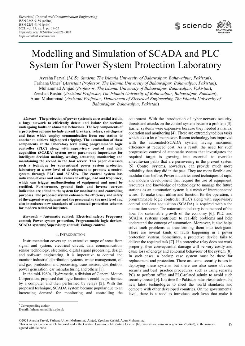
PLC software selected is Siemens TIA Portal. It can migrate projects to STEP7 and online diagnostic function is available which is fast and easy. The up-to-date series of Siemens PLC are S7-1200 and S7-1500. PLC shown in Fig. 2 is the PLC used for the proposed controlled system. After the selection of PLC type, the next step is to download and install the PLC software according to the PLC type. After downloading and installing the PLC software, next task is to make an algorithm for the control system. The algorithm should be short and simple enough to understand because long programs have disadvantages such as memory consumption taking a large number of I/O, which increases the price of PLC.
Fig. 2. PLC module used for the proposed system.
IV. SUPERVISORY CONTROL AND DATA ACQUISITION (SCADA)
Modern SCADA systems can uplift industries by providing strong and impactful operators that give users a view of real-time operation [17]. They are used to maximise efficiency and optimise even greater power distribution. They can be utilised to arrange data in several ways and simplify the analysis using graphical user interfaces (GUIs). Both terminologies work side
by side but as the existing labs are unable to provide high-class equipment, firstly, labs must be automated to advance levels of power system protection and then they must be utilised in every efficient way possible. However, SCADA system is generally a scheme that is usually used for supervision and monitoring purposes [18], [19].
A SCADA system is made to control and monitor the whole system and this system is upgraded with improving computer technology [20]. The control program designed will monitor the system and if any error or fault occurs, it will show that error by generating an alarm. If a relay detects any fault that is connected to PLC, it will process the fault and send data to HMI that will show the fault with all information. A PLC is connected to a PC through a compatible cable for communication between the two. PLC works as intermediate equipment. The PLC used is connected to a DC supply and the other 24 V DC is required for PLC to energize its input. The desired equipment is connected to the output of PLC. SCADA system is established to use standard protocol communication. Alarms are introduced to alert in case of a fault. This makes the system more integrated to meet the needs of users. It makes the small process and large control easy for the operator. The SCADA system can generate an automated report and send it to the supervisor. This report can be generated and sent in different periods according to the design and requirement. After making the algorithm, next step is to implement that algorithm in order to make a control program. Once a program is made, it is compiled and checked for errors. If any error occurs, it is removed and again compiled until all errors are removed. After compiling, the program is simulated.
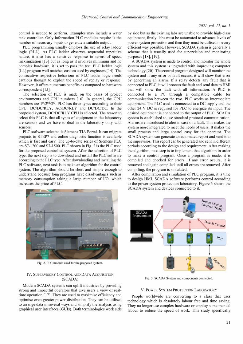
After compilation and simulation of PLC program, it is time to design HMI. SCADA software performs control according to the power system protection laboratory. Figure 3 shows the SCADA system and devices connected to it.
Fig. 3. SCADA System and components connected.
V. POWER SYSTEM PROTECTION LABORATORY People worldwide are converting to a class that uses
technology which is absolutely labour free and time saving. They no longer use complex hardware or employ some manual labour to reduce the speed of work. This study specifically
Electrical, Control and Communication Engineering
________________________________________________________________________________________2021, vol. 17, no. 1
22
revolves around a power protection system that will be used in laboratories. The system designed for such a purpose will be in charge of a continuous power supply to the consumer in a reliable way [9]. As mentioned earlier, designing such a system will automatically reduce the cost factor and also have lower maintenance. By programming power system laboratory equipment to the latest standards, we will be able to transform our laboratories to meet the international criteria that will also provide faster responses to faults in the system, thus increasing its reliability. A detail of such events is discussed below that will provide enough information to understand what PLC and SCADA are and how they are modelled and simulated for power protection laboratory.
To start with the process, first, we have to install sensors in the protection system. These sensors work as an alarm that will alert us of anything unwanted. They are basically installed for the detection of an unusual entity and then convert it into a useful result that can be measured. Next task is the instalment of PLC that will be able to decode the data coming from sensors or the relays. In the third part, an interface is designed specifically for HMI. This interface basically allows an operator to connect with the controller of the system. It has hardware and software that take inputs from a user to be translated into signals for machines, which will provide the required output as a result. Lastly, a SCADA system is implanted which will control, monitor and supervise the above products compiled in a form of system.
The automation system designed will be based on the integration of the following systems that are built prior to the main systems. Sensors and relays are interfaced with the central control unit (CCU) through some devices at the end.
• PLC which is the control unit at this stage will send an output based on input and send it to the circuit breakers and other equipment that are protection controlled.
• All of this will be monitored through HMI details which are mentioned above. It will also control the process being the face of the functional logic of the system.
By performing this lab, students will be able to automate any
system related to any field by programming the PLC and SCADA system.
A. Configuration in PLC Software Siemens has made many PLC line products in the family of
SIMATIC S7, i.e., S7-200, 300 and 400. For automation, Step 7 is a powerful software solution for Siemens. It has a programming environment for Siemens PLCs. The unique feature of this software is the construction of reusable logic, single integration of numerous automation devices and controlled program architecture.
First, it is necessary to install Soft PLC that comes with Hardware of PLC. After installing PLC software logic is made according to the laboratory system. For the development of an algorithm of a program, a proper set of strategy must be charted during program implementation and its organisation. To plan a program after developing a description, a flow chart can be used for it. The flow chart allows for better understanding of sequence and tells how to sort out. It represents the process, analysis, record, communication and sequence of the control process. Defining a control task is the first step of the control
program. It tells about what must be done. These tasks depend on the operation of the instrument. Defining a control strategy is the second step in the development of a control program. To generate the desired control output, order for those programming steps should occur within the program. This is also called the development of the algorithm.
B. TIA Portal In the proposed system, software in the TIA Portal is used.
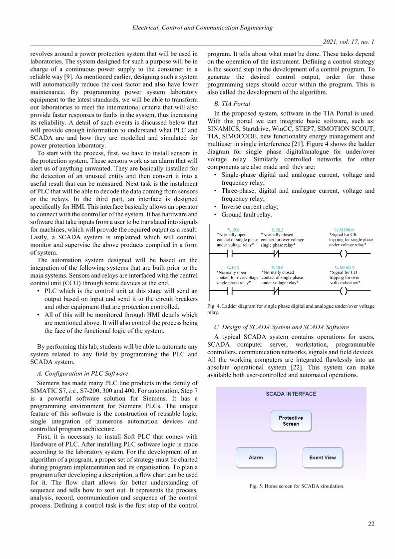
With this portal we can integrate basic software, such as: SINAMICS, Startdrive, WinCC, STEP7, SIMOTION SCOUT, TIA, SIMOCODE, new functionality energy management and multiuser in single interference [21]. Figure 4 shows the ladder diagram for single phase digital/analogue for under/over voltage relay. Similarly controlled networks for other components are also made and they are:
• Single-phase digital and analogue current, voltage and frequency relay;
• Three-phase, digital and analogue current, voltage and frequency relay;
• Inverse current relay; • Ground fault relay.
Fig. 4. Ladder diagram for single phase digital and analogue under/over voltage relay.
C. Design of SCADA System and SCADA Software A typical SCADA system contains operations for users,
SCADA computer server, workstation, programmable controllers, communication networks, signals and field devices. All the working computers are integrated flawlessly into an absolute operational system [22]. This system can make available both user-controlled and automated operations.
Fig. 5. Home screen for SCADA simulation.

Electrical, Control and Communication Engineering
________________________________________________________________________________________2021, vol. 17, no. 1
23
Flutek WinTr software has been used for SCADA programming, which has two kinds of features: standard features and optional features. Standard features in a single package have runtime and development module, cutaway, symbol factory, dundas chart, alarm-view, VB and SQL server. Optional features include print server, reports, SMS, emails, WinTr server, PLC drivers for Modbus, RTU, Profitnet, PPI and S7 MPI. WinTr-SCADA trumped-up is divided into runtime and development with the following competence. Warning and Alarms are used for operation values. For the good and complete understating of power system protection laboratory, it is required to first understand the control of all sensors available in the laboratory. For this purpose, all experiments are performed in the laboratory on different sensors. Figure 5 shows the home screen for the SCADA system and Fig. 6 shows HMI screen for the Power Protection System Laboratory. The main screen contains a different button by using which we can go on another screen.
Fig. 6. Protection screen for SCADA system control according to power protection laboratory of university.
D. Undervoltage Detection at Single Phase for Digital/Analogue Relay
An experiment has been done to detect undervoltage for digital/analogue relay at single phase (Fig. 7). The value is set as 1.5 V for undervoltage condition. As voltage is dropped to the set value on sensor of 1.5 V, it sends a signal to PLC software through CPU connected. It will show a green line. The green line shows the power flow. Blue dotted lines indicate disconnectivity. As the fault has occurred, it appears on the projection screen. The associated green LED will turn into red and it will show Fault. Single-phase relay can be connected to any phase. It is connected to the blue phase so when the fault occurs the corresponding blue under-voltage LED turns into red on a protection screen. Figure 7 shows the undervoltage fault for digital/analogue relay at single-phase and Fig. 8 below shows the fault in HMI. It tells that relay is connected at the red phase.
Fig. 7. PLC simulation for under-voltage fault for digital/analog relay at a single phase.
Fig. 8. Fault occurred at single phase undervoltage for digital/analogue relay in HMI.
E. Protection Scheme Used in Programming If the voltage is below or above the prescribed limit than a
protection scheme activates and send signals to a circuit breaker, which turns off the system. Figure 9 shows the protection scheme of under/overvoltage for analogue/digital relay.
Fig. 9. Protection scheme of under/overvoltage for analogue/digital relay.
If a sensor undergoes any internal fault or gets damaged, it starts giving a signal. This case is very rare. However, if it happens, a circuit breaker will turn on and protect the system.
VI. CONCLUSION A controlled and monitored system for power system
protection laboratory has been introduced. The proposed system will enhance the existing power protection systems used conventionally in Pakistan to an advanced level that will be reliable and require less cost and maintenance. It will basically transform manual operation to the digital, create an automatic and user-friendly system that will reduce labour costs and

Electrical, Control and Communication Engineering
________________________________________________________________________________________2021, vol. 17, no. 1
24
provide an efficient solution to the problem despite the traditional ways. The present research further emphasises that PLC and SCADA systems that are now used worldwide should be taught as a regular course to students as they will use this technology in industries and at home. It can be seen from the proposed system that people have become more aware of PLC and SCADA systems than before as these products contribute to solving the real-life problems and help understand the concept of automation. It is not possible to make a record and control a laboratory in a remote area. If new instruments are introduced in a power system protection laboratory in future, they will easily be adjustable with this programming and compatible with this controller as it provides a large range of I/O and additionally I/O can be added. The newly built protection system based on automation tools will be reliable and time saving. The proposed system that will cost less and have minimum maintenance can be extended to several protection schemes and can be applied to other laboratories.
REFERENCES [1] K. I. Wong and T. U. Siaw, “PLC and SCADA Laboratory Experiments
for a Final Year Instrumentation Course,” Int. J. Inf. Educ. Technol., vol. 5, no. 11, pp. 865–868, 2015. https://doi.org/10.7763/IJIET.2015.V5.628
[2] E. R. Alphonsus and M. O. Abdullah, “A review on the applications of programmable logic controllers (PLCs),” Renew. Sustain. Energy Rev., vol. 60, pp. 1185–1205, 2016. https://doi.org/10.1016/j.rser.2016.01.025
[3] X. Yu and C. Singh, “A practical approach for integrated power system vulnerability analysis with protection failures,” IEEE Trans. Power Syst., vol. 19, no. 4, pp. 1811–1820, 2004. https://doi.org/10.1109/TPWRS.2004.835656
[4] C. P. Janssen, S. F. Donker, D. P. Brumby, and A. L. Kun, “History and future of human-automation interaction,” Int. J. Hum. Comput. Stud., vol. 131, pp. 99–107, 2019. https://doi.org/10.1016/j.ijhcs.2019.05.006
[5] IEEE Standard for SCADA and Automation Systems, IEEE Std C37.1-2007, vol. 23, no. 6, 2007.
[6] C. Lin, X. Min, and J. Junru, “Exploration on Educational Reform of Electrical Engineering and Automation Professional,” 2019 Asia-Pacific Conference on Advance in Education, Learning and Teaching (ACAELT 2019), pp. 1321–1325, 2019.
[7] B. Ram and D. N. Vishwakarma, Power System Protection and Switchgear. McGraw-Hill Professional Publishing, 2011.
[8] M. Eremia and M. Shahidehpour, Handbook of Electrical Power System Dynamics: Modeling, Stability, and Control. The Institute of Electrical and Electronics Engineers, Inc., 2013. https://doi.org/10.1002/9781118516072
[9] M. S. Thomas, P. Kumar, and V. K. Chandna, “Design, development, and commissioning of a supervisory control and data acquisition (SCADA) laboratory for research and training,” IEEE Trans. Power Syst., vol. 19, no. 3, pp. 1582–1588, 2004. https://doi.org/10.1109/TPWRS.2004.826770
[10] J. F. M. valter Pinto, Silviano Rafeal, “PLC controlled industrial processes on-line simulator,” IEEE Int. Symp. Ind. Electrnics, 4–7 June, 2007. https://doi.org/10.1109/ISIE.2007.4375084
[11] D. Li, Y. Serizawa, and M. Kiuchi, “Concept design for a Web-based Supervisory Control and Data-Acquisition (SCADA) system,” Proc. IEEE Power Eng. Soc. Transm. Distrib. Conf., vol. 1, ASIA PACIFIC, pp. 32–36, 2002.
[12] R. Bayindir and Y. Cetinceviz, “A water pumping control system with a programmable logic controller (PLC) and industrial wireless modules for industrial plants-An experimental setup,” ISA Trans., vol. 50, no. 2, pp. 321–328, 2011. https://doi.org/10.1016/j.isatra.2010.10.006
[13] J. L. Vazquez-Gonzalez, J. Barrios-Aviles, A. Rosado-Muñoz, and R. Alejos-Palomares, “An industrial automation course: Common infrastructure for physical, virtual and remote laboratories for PLC programming,” Int. J. Online Biomed. Eng., vol. 14, no. 8, pp. 4–19, 2018. https://doi.org/10.3991/ijoe.v14i08.8758
[14] D. Cousineau, D. Mentré, and H. Inoue, “Automated deductive verification for ladder programming,” Proceedings F-IDE 2019, EPTCS, vol. 310, pp. 7–12, 2019. https://doi.org/10.4204/EPTCS.310.2
[15] H. A. Abbas, “Future SCADA challenges and the promising solution: The agent-based SCADA,” Int. J. Crit. Infrastructures, vol. 10, no. 3/4, pp. 307–333, 2014. https://doi.org/10.1504/IJCIS.2014.066354
[16] R. K. Chauhan, M. L. Dewal, and K. Saini, “Utility of SCADA in power generation and distribution system,” Proc. 2010 3rd IEEE Int. Conf. Comput. Sci. Inf. Technol. ICCSIT 2010, vol. 6, pp. 648–652, 2010.
[17] T. Adams, “SCADA System Fundamentals,” Course No: E01-007, pp. 3–5, 2014.
[18] R. Slusariuc, L. Samoila, G. Popescu and A. D. Handra, “SCADA Systems Analysis For Industrial Procesess,” Annals of the University of Petrosani, Electrical Engineering, vol. 21, pp. 17–22, 2019.
[19] H. Salih, H. Abdelwahab, and A. Abdallah, “Automation design for a syrup production line using Siemens PLC S7-1200 and TIA Portal software,” Proc. 2017 Int. Conf. Commun. Control. Comput. Electron. Eng. ICCCCEE 2017, pp. 5–9, 2017. https://doi.org/10.1109/ICCCCEE.2017.7866702
[20] S. L. Jämsä-Jounela, “Future trends in process automation,” IFAC Proc. Vol., vol. 40, no. 1, pp. 1–10, 2007. https://doi.org/10.3182/20070213-3-CU-2913.00003
[21] S. SIMATIC, “S7-1200 Easy Book,” pp. 1–454, 2015. [22] L. Prenzel and J. Provost, “PLC Implementation of Symbolic, Modular
Supervisory Controllers,” IFAC-PapersOnLine, vol. 51, no. 7, pp. 304–309, 2018. https://doi.org/10.1016/j.ifacol.2018.06.317
Ayesha Faryal received her B. Sc. and M. Sc. degrees in Electrical Engineering from NFC Institute of Engineering & Technology, Multan and the Islamia University of Bahawalpur, Pakistan in 2017 and 2020, respectively. Her areas of research include controlling, power protection system, transmission, modelling of SCADA systems, programmable logic controllers (PLC), integration of PLC and SCADA systems and automation of home appliances and laboratories. Address: Department of Electrical Engineering, the
Islamia University of Bahawalpur, 63100, Bahawalpur, Pakistan. E-mail: [email protected]
Farhana Umer received PhD degree from the School of Electrical/Electronics Engineering, Selcuk University, Turkey in 2017. She received her M. E. degree in Electrical Power Engineering from Mehran University of Engineering & Technology, Pakistan, in 2013. She worked as a Lecturer at the department of Electrical Engineering, the IUB from 2009 to 2016. Now she is an Assistant Professor at the Department of Electrical Engineering, the Islamia University of Bahawlpur, Pakistan. Her research interests include transient analysis of power systems, distributed energy
generation and power system analysis. Address: Department of Electrical Engineering, the Islamia University of Bahawalpur, 63100, Bahawalpur, Pakistan. E-mail: [email protected] ORCID iD: https://orcid.org/0000-0002-5392-7964
Muhammad Amjad received PhD degree from the University of Technology, Malaysia, in 2013. He has been working as a Professor at the Department of Electronic Engineering, the Islamia University of Bahawalpur, Pakistan since 1999. In addition, he is serving as the Dean of the Faculty of Engineering at the same university. He has published several conference papers and more than 21 papers in well reputed international journals. His research interests include advanced power electronics, fuzzy logic control particle swarm optimization, design of model
predictive controller for machine design and implementation of transformerless ozone implementation using LCL filters. Address: Department of Electronic Engineering, the Islamia University of Bahawalpur, 63100, Bahawalpur, Pakistan. E-mail: [email protected]

Electrical, Control and Communication Engineering
________________________________________________________________________________________2021, vol. 17, no. 1
25
Zeeshan Rashid received PhD degree from Koc University, Istanbul, Turkey in 2018. Currently, he is working as an Assistant Professor at the Department of Electrical Engineering, the Islamia University of Bahawalpur, Pakistan. His research interests include modelling of fibre lasers, harmonic wave propagation in smart grids, and high frequency distortion in underground cables, model predictive control and modelling of low voltage power circuits at harmonic frequencies in a smart network.
Address: Department if Electrical Engineering, the Islamia University of Bahawalpur, 63100, Bahawalpur, Pakistan. E-mail: [email protected]
Aoun Muhammad did his M. Sc. Electrical Engineering from University of Engineering and Technology, Lahore, Pakistan in 2011. He did his B. Sc. Electrical Engineering from Bahauddin Zakariya University, Multan, Pakistan in 2006. He worked as a lecturer at the department of Electronic Engineering 2007–2015. Since 2015 he is an Assistant Professor at The Islamia University of Bahawalpur, Pakistan. His research interests are power electronics and power
systems analysis. E-mail: [email protected]