OFSOPC with Citect SCADA 2016 - Explore Exchange ...
35
OFSOPC with Citect SCADA 2016 April 2017 - White paper Martin Lalanne
-
Upload
khangminh22 -
Category
Documents
-
view
4 -
download
0
Transcript of OFSOPC with Citect SCADA 2016 - Explore Exchange ...

OFSOPC with Citect SCADA 2016
April 2017 - White paper
Martin Lalanne

OFSOPC with Citect SCADA 2016
2
Summary
I. Introduction 3
1.1 Architecture Overview 3 1.2 SCADA Project 4 1.3 Computer Selection 4 1.4 PAC Selection 4 1.5 PAC Sizing 5 1.6 PAC Scan Cycle 6
II. Citect SCADA Communication 7
2.1 Communications Overview 7 2.2 Citect SCADA Communications detail 9
III. OFSOPC Driver 10
3.1 OFS Internal Architecture 10 3.2 OPC Communications 10 3.3 OFSOPC Driver 11 3.4 Startup and Redundancy 12
IV. OFS Configuration 13
4.1 OFS Alias 13 4.2 OFS Communication Parameters 25 4.3 OFS Options 25
V. Citect SCADA Fast Link 27
5.1 Import PAC Tags with Fast Link 27 5.2 Add / Modify / Delete Tags 30
VI. Performance 32
6.1 SCADA Redundancy 32 6.2 PAC Redundancy 33 6.3 PAC Scantime 33 6.1 OFS Server communication modes 34

OFSOPC with Citect SCADA 2016
3
I. Introduction
Applies to:
Citect SCADA 2016
OFS 3.60 SP2
OFSOPC V2.05.46
Modicon M340, M580 and M580 HSBY
Unity Pro v11.1
Summary:
This document will illustrate how to set up Citect SCADA, the OFSOPC driver and OFS to communicate
with Schneider PACs.
This document will also describe the Citect SCADA best practices, OFSOPC driver configuration, OFS
setup as well as the communication capabilities of Schneider Electric PACs; M340 (BMX P34 2020),
M580 (BME H58 4040), M580 Hot Standby (BME H58 6040).
1.1 Architecture Overview
Figure 1: System Architecture Overview

OFSOPC with Citect SCADA 2016
4
1.2 SCADA Project
Two test projects were used to provide results in this document.
Project 1:
10,000 I/O | 3,750 Alarms | 6,250 Trends
2,500 Analog | 7,500 Digital tags
Project 2:
20,000 I/O | 7,500 Alarms | 12,500 Trends
5,000 Analog | 15,000 Digital tags
Both projects were built and run with the following characteristics:
25 / 75 per cent split between analog and digital points
Two per cent of analogs change every seconds
One per cent of digitals change every 60 seconds
The simulation is focused on providing a base load to allow realistic timing measurements.
1.3 Computer Selection
The SCADA servers run on physical PC machines with the following specifications:
Windows Server 2012 R2
Intel Core i7-3770 CPU 3.40 GHz
16 Gb RAM
Hard Drive 2 Tb
1.4 PAC Selection
A number of different models were selected to explore the different performance characteristics of each PAC. A total of three PACs with varying sizes and capabilities were chosen.
M340 PAC System
The M340 is a compact mid-range PAC suited to process control and industrial applications. It is capable of supporting various industrial protocols by installing optional communication modules. It also forms part of the Ethernet Remote I/O solution.
The built in CoPro was chosen as the communications channel for SCADA-to-PAC communications. This is the preferred channel, due to increased throughput and capabilities.
Additional communications modules can be added for dedicated programming, PAC-to-PAC communications, I/O scanning, global data and many other industrial protocol standards.

OFSOPC with Citect SCADA 2016
5
M580 PAC System
The M580 is a compact high-range PAC. It is suitable for a number of medium to large sized applications requiring advanced control, scalability and flexibility. It is capable of supporting various industrial protocols by installing optional communication modules. It also forms part of the Ethernet Remote I/O.
The CPU Channel was chosen as the communications channel for SCADA-to-PAC communications. This is the preferred channel, due to increased throughput and capabilities.
Additional communications modules can be added for dedicated programming, PAC-to-PAC communications, I/O scanning, global data and many other industrial protocol standards.
M580 Hot Standby PAC System
The M580 hot standby system provides high speed exchange capacity and the I/O sizing requirements for large projects. It was chosen to demonstrate the PAC redundancy performance capabilities for the SCADA-to-PAC channel with OFSOPC.
1.5 PAC Sizing
The following table summarizes the type, tag count and channel selected for communications with SCADA:
PAC Type Comm Channel Max Number Requests per Scan per Channel
Tag Count
M340-BMXP342020 Stand-alone CoPro 12 10,000 (Project 1)
M580-BMEP584040 Stand-alone CPU
NOR
24
16
20,000 (Project 2)
M580-BMEH586040 Hot standby CPU 32 20,000 (Project 2)
Table 1: PAC Details
For all controllers the server processes the requests at the beginning of the scan. The resources available to process requests depend on the controller model.
The server communication resource of a PAC can be adjusted using the system word %SW90. Adjusting this parameter will adjust the maximum number of requests the PAC can handle per CPU scan.
PAC Default Maximum Value Used
M340-BMXP342020 8 12 12
M580-BMEP584040 32 40 32
M580-BMEH586040 56 64 56
Table 2: Number of Requests PAC Configuration

OFSOPC with Citect SCADA 2016
6
1.6 PAC Scan Cycle
Figure 2: Synchronous PAC Scan Cycle
The figure above illustrates the synchronous scan cycle of the PAC. It can be seen that communications processing occurs at the start of scan. This information should be taken in the context of the number of requests the CPU can process per scan. It is also important to note that the PAC scan time can impact the communications performance and throughput.

OFSOPC with Citect SCADA 2016
7
II. Citect SCADA Communication
2.1 Communications Overview The following diagrams provide a high level overview of the communications configuration for Citect SCADA, OFS and PAC controllers. The current architecture of the OFSOPC driver only supports having Citect SCADA and OFS on the same physical machine. It is therefore important to note that most communication delays and optimization will be on the link between the OFS Server and the PACs. We advise that the channel between OFS and the PAC should therefore first be analysed and optimized, before modifying any SCADA parameters. The first diagram focuses on the Primary SCADA Server and the second diagram focuses on the Standby SCADA Server.
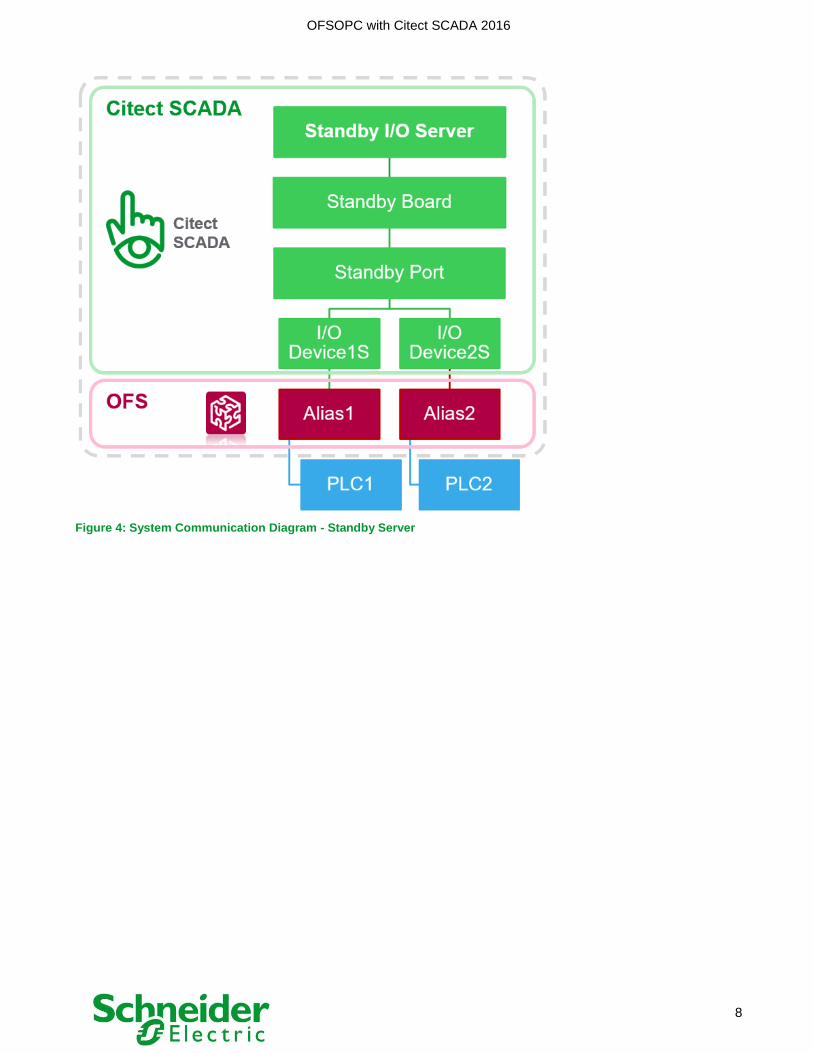
Important: One port is recommended to host several I/O Devices with the OFSOPC Driver
Primary SCADA server:
Figure 3: System Communication Diagram - Primary Server
Standby SCADA server:
OFSOPC with Citect SCADA 2016
8
Figure 4: System Communication Diagram - Standby Server
OFSOPC with Citect SCADA 2016
9
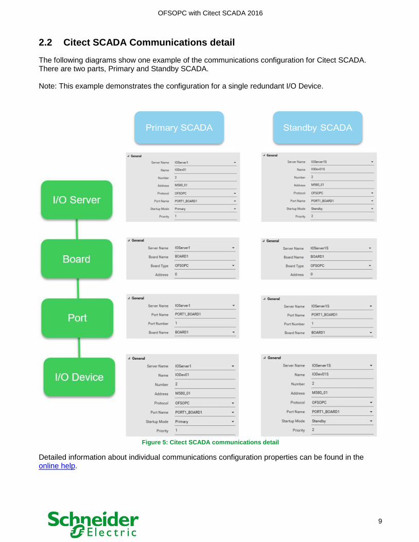
2.2 Citect SCADA Communications detail
The following diagrams show one example of the communications configuration for Citect SCADA. There are two parts, Primary and Standby SCADA. Note: This example demonstrates the configuration for a single redundant I/O Device.
Figure 5: Citect SCADA communications detail
Detailed information about individual communications configuration properties can be found in the online help.

OFSOPC with Citect SCADA 2016
10
III. OFSOPC Driver
3.1 OFS Internal Architecture The OPC Factory Server (OFS) is composed of three main components:
1. A communication task (COM Handler) which manages communication with a device
2. A shared memory area (Cache Memory)
3. An OPC task that manages groups and OPC method access from groups
The figure below shows the internal architecture of the OFS server:
Figure 6: OFS internal architecture
3.2 OPC Communications
This section will describe the typical behaviour of the Citect SCADA OFSOPC driver (OPC client) connecting to OFS. When the I/O server starts, the OFSOPC driver creates three OPC groups for each I/O Device with different update rates using the notification mechanism:
- Group 1 with 400ms update rate (created with name “<OFSAlias>_GROUP_1”)
- Group 2 with 1s update rate (created with name “<OFSAlias>_GROUP_2”)
- Group 3 with 3s update rate (created with name “<OFSAlias>_GROUP_3”)
The three OPC groups are first created as inactive. The OFSOPC driver then adds all items (configured variable tags) as active in Group 1. A status tag <OFSAlias>!#PLCQualStatus which has its own OPC group (“STATUS_GROUP”) is read. If it returns healthy status, the driver will set the three groups active, which effectively brings the unit online and OFS starts polling the device. As the different subscription rates for each variable tag stabilise, items are moved between OPC groups to best match the requested update rate. Two additional groups are created by OFS for PAC Status and data dictionary management:
- Group at 500ms for the PAC Status
o <OFSAlias>!#PLCQualStatus
o <OFSAlias>!#PLCDataDicReady
- Group at 2s which is managing the consistency of data dictionary with service requests
On the OPC Handler side several groups will be created and refreshed to satisfy the OFSOPC driver requested update rates. On the controller communication side (COM Handler), three groups will be created with update rates of 400ms, 1s and 3s. The communications for each group period will be calculated and optimized in order to send the minimum number of requests to the controller.

OFSOPC with Citect SCADA 2016
11
Each time an item is activated or deactivated the request optimization will re-evaluate the communication requests. Within the created groups the items added by the OFSOPC driver will be either active or inactive depending on the need of the SCADA system. In general, the alarm and trend items will always be active, while for visualization only the displayed items are active. Other items that are not requested are not exchanged between the OFS and the controller. This mechanism optimizes the communication between OFS and the controller, sending the minimum amount of data to satisfy all requests. When a new page is displayed on the SCADA system, the OFSOPC driver activates the item and promotes it into the group with the required update rate. It then disables any items that were previously displayed but no longer required. The deactivation time is five (5) seconds.
3.3 OFSOPC Driver
It is recommended to use the latest version of the OFSOPC driver that is available. This document targets OFSOPC V2.05.46.00000 or greater. The OFSOPC driver defines three groups per I/O device. These groups are polled at a rate defined by the [OFSOPC]Group<i>UpdateRate parameter in citect.ini.
These poll rates should be set such that:
Group1UpdateRate < Group2UpdateRate < Group3UpdateRate
Group1UpdateRate < AlarmScanTime
Group2UpdateRate < Fast trend sampling time
Group3UpdateRate < Slow trend sampling time
The default values are:
Group1UpdateRate = 400ms
Group2UpdateRate = 1000ms
Group3UpdateRate = 3000ms
The minimum group update rate is 50ms in OFS 3.60 SP2. This parameter is fixed and can’t be changed. Each requested tag will be added in the group which provides the lowest (e.g. fastest) update rate and the one that is faster than the requested rate. For example, a tag with a request rate of 2s will be activated in Group 2 if the default values are being used.
If no group provides such a rate, then Group 1 (the fastest group) is used. For example, tags requested at 200ms with default configuration will be put in the 400ms group.
Usually Group 1 is associated with variable tags in the active display page and alarms. Group 2 is typically targeted for use by trends and Group 3 is there for slow trends if they are configured.

OFSOPC with Citect SCADA 2016
12
3.4 Startup and Redundancy On startup, the OFSOPC driver connects to OFS and checks the connection status of the device. The I/O device with the best availability and highest priority will become activate first.
The OFSOPC driver adds five groups for each device.
Figure 7: OFS groups in Client window
The groups are initially in the inactive state except for the Status group.
Items are added in the inactive groups in the active state.
Once all items are added, the OFSOPC driver enables the group for primary devices.
On the standby machine the groups are in the inactive (disabled) state.
During a redundancy switchover event, the OFSOPC driver on the Standby I/O Server sets the
groups active, which enables communications to the controller.

OFSOPC with Citect SCADA 2016
13
IV. OFS Configuration
Schneider Electric’s OPC Factory Server (OFS) is required to be installed on each Citect SCADA I/O Server, as DCOM is not supported by the OFSOPC driver. The following section details the OFS configuration used in this example and makes some recommendations regarding key parameter settings for better performance.
4.1 OFS Alias The alias configuration is important to optimize communication between OFS and the controller. This section describes how to optimize the settings of an alias.
4.1.1 Add Device Alias
In the OFS Configuration Tool, create a New Device Alias in the Device overview section.
Define a name. This name will be use in Citect SCADA for the IO Devices communication.
Define the IP address of the PAC in Device address A for a single communications channel.
Figure 8: OFS Alias configuration

OFSOPC with Citect SCADA 2016
14
4.1.2 Dual communication channels
OFS can support two communication channels to each PAC. In this example, the M580 PAC has an additional channel with the NOR communication module. In OFS one address is defined for the M580 CPU module and one for the NOR communication module. Both modules are connected to the Plant Network which provides a redundant link to communicate between the M580 PAC and OFS (which serves the Citect SCADA system). This removes complexity from the Citect SCADA configuration as you only define a single I/O device, while OFS handles the dual channel communication.
Figure 9: M580 PAC Overview in Unity Pro
For dual channel configuration in OFS, enter the second IP address in Device address B.
Figure 10: OFS Alias configuration – Dual communication channels
If Device address A is not available, OFS will automatically switch to Device address B
Figure 11: Diagnostic window logs in OFS Server
Device address B will become the Primary address

OFSOPC with Citect SCADA 2016
15
Figure 12: OFS network window for M580 PAC
Once Device address A is available again, it will be the Primary address for OFS only if Device address B is shutdown or the OFS Server is restarted.
4.1.3 PAC Hot Standby Configuration
The OFS configuration with Hot Standby Controller (M580 HSBY) only needs a unique Main IP Address. It should be noted that the Standby PAC address corresponds to the Main IP +1. The SCADA system must not use the Standby PAC address (Main IP+1), since no control commands are processed. Only the Main can handle control commands and manages synchronisation with the Standby.
Note: Do not use the Standby PAC IP address for communication with SCADA
Define the Main IP address for the PAC in the first field in IPConfig tab in Unity. This address is
used by the SCADA system for communications. The IP+1 is created automatically for the
redundant PAC (Standby).
Figure 13: Unity Pro PAC – Main IP & IP+1 addresses
Use only the Primary PAC IP address in OFS configuration.

OFSOPC with Citect SCADA 2016
16
Figure 14: OFS configuration with the main PAC IP address
4.1.1 OFS communication Modes
There are different scenarios to configure OFS communication:
XVM Symbol table file only
XVM Symbol table file & Using Data Dictionary
Using Data Dictionary only
Figure 15: OFS communication mode overview

OFSOPC with Citect SCADA 2016
17
4.1.1.1 Data dictionary
In Unity Pro, open Project Settings and select the Data dictionary option.
Figure 16: Data dictionary setting in Unity Pro
Select “Only HMI variables” when variables are configured with the HMI variable option. This
allows OFS to load only the HMI variables from the PAC. It also optimises the size of the Data
Dictionary that is then stored in the PAC memory.
Figure 17: Variables in Unity Pro with HMI variable option
In the OFS Configuration Tool, select Using Data Dictionary and No Communication Break
options. If No Communication Break is set, While OFS server is copying the new data
dictionary, OFS will continue to use old one.

OFSOPC with Citect SCADA 2016
18
Figure 18: OFS Alias configuration data links
4.1.1.2 Symbol Table (XVM)
To generate XVM file, export Variables in Unity Pro on the XVM format.
Figure 19: Generate Symbol Table XVM in Unity Pro

OFSOPC with Citect SCADA 2016
19
In OFS configuration, specify the symbol table file (XVM) path.
Figure 20: OFS configuration with Symbol Table XVM
Note: It is possible to combine Data Dictionary and Symbol table file. More details about the performance can be found in section 6.1.
Figure 21: OFS configuration with Symbol Table XVM and Data Dictionary

OFSOPC with Citect SCADA 2016
20
Define Consistency level for Symbol table file
- Strict Mode: OFS will stop communicating to the controller when there is any mismatch between the
controller and XVM signatures. Once XVM signatures match, it starts communicating.
- Debug Mode: OFS will ignore any minor changes like changed code, comment added, Tag added in
the controller
Figure 22: Consistency level mode
4.1.2 OFS Parameters The key parameters to adjust communication with the controller are the Max Channels and Max Pending parameters.
Max Pending – the number of requests that are allowed to be sent in parallel to the controller
Max Channels – the maximum number of TCP/IP connections that OFS will open with the
controller
By default, MaxChannels = 1 and MaxPending = 0
MaxPending: Number of requests that are allowed to be sent in parallel to the controller A setting of MaxPending=0 means the OFS server automatically detects the PAC’s target communications port and decide how many parallel requests may be sent at the same time. OFS will choose the appropriate MaxPending value using a predefined table of communication modules. It is preferable to let OFS choose the value of the MaxPending parameter, unless a new release of a PAC firmware changes the capability of the device.

OFSOPC with Citect SCADA 2016
21
In case of multiple OFS connections to the same PAC (redundant IO Server), it is recommended to set MaxPending to the capacity of the channel (refer to Table 1: PAC Details). This number depends on the PAC type and the number of channels the user wants to configure on the PAC for OFS. Max Channels: Maximum number of TCP/IP connections that OFS will open with the controller It should be considered that for Unity devices (frame length = 1023 Bytes) the TCP/IP stack is able to buffer up to 4 KB. Therefore, it is possible to configure MaxChannels = MaxPending / 4 By increasing the number of channels, it increases the communications "fault tolerance" if a connection becomes unavailable. It also makes it possible to send parallel requests and increases the reliability of the communication by distributing the load.
4.1.3 Identifying request requirements for the Alias
From OFS, it is possible to view the number of requests needed to refresh items from a specific group.
When OFS is running, in the General menu, select Network Window and then select the
appropriate device.
Figure 23: OFS network windows
Expand the Nb Timers section as shown below:
Figure 24: OFS network window for M580 PAC

OFSOPC with Citect SCADA 2016
22
Net Request gives you the number of requests needed for each group. In this example we can see that 27 requests (Total of Net Request across all groups) are needed to retrieve all data from the controller. Information for this controller in terms of response times is also available. Average Access Time is the time typically taken for the controller to respond to OFS requests (12 ms). Max Channels and Max Pending parameters configuration with the M580 system: To fully exploit the bandwidth of the M580 PAC, the following OFS configuration is recommended. For the M580 PAC in our test system, two channels with different communications capabilities are present. The CPU channel is capable of processing 24 requests per CPU scan, while the NOR channel is capable of processing 16 requests per CPU scan. We must set the number of pending requests such that the channel capability is not exceeded. Therefore, the Max Pending value of 16 is selected. From OFS diagnostics, it can be seen that 27 requests will be processed in two (2) CPU cycles if we consider that 16 requests are processed per CPU cycle. In this example it is recommended that the Max Channels is set to 4 and Max Pending is set to 16 for the Alias configuration in OFS.
Figure 25: Max Channels and Max Pending
Given the details above the following OFS configuration is used for each controller:
PAC MaxChannels MaxPending
M340 3 12
M580 4 16
M580 HSBY 8 32
Table 3: OFS configuration Details

OFSOPC with Citect SCADA 2016
23
The following figures detail the M340 which is used in the example calculation above.
Figure 26: OFS network window for M340 PAC Figure 27: OFS Configuration adjustment for M340 PAC
The following figures detail the M580 Hot Standby
Figure 28: OFS network window for M580 HSBY PAC Figure 29: OFS Configuration adjustment for M580 HSBY
OFSOPC with Citect SCADA 2016
24
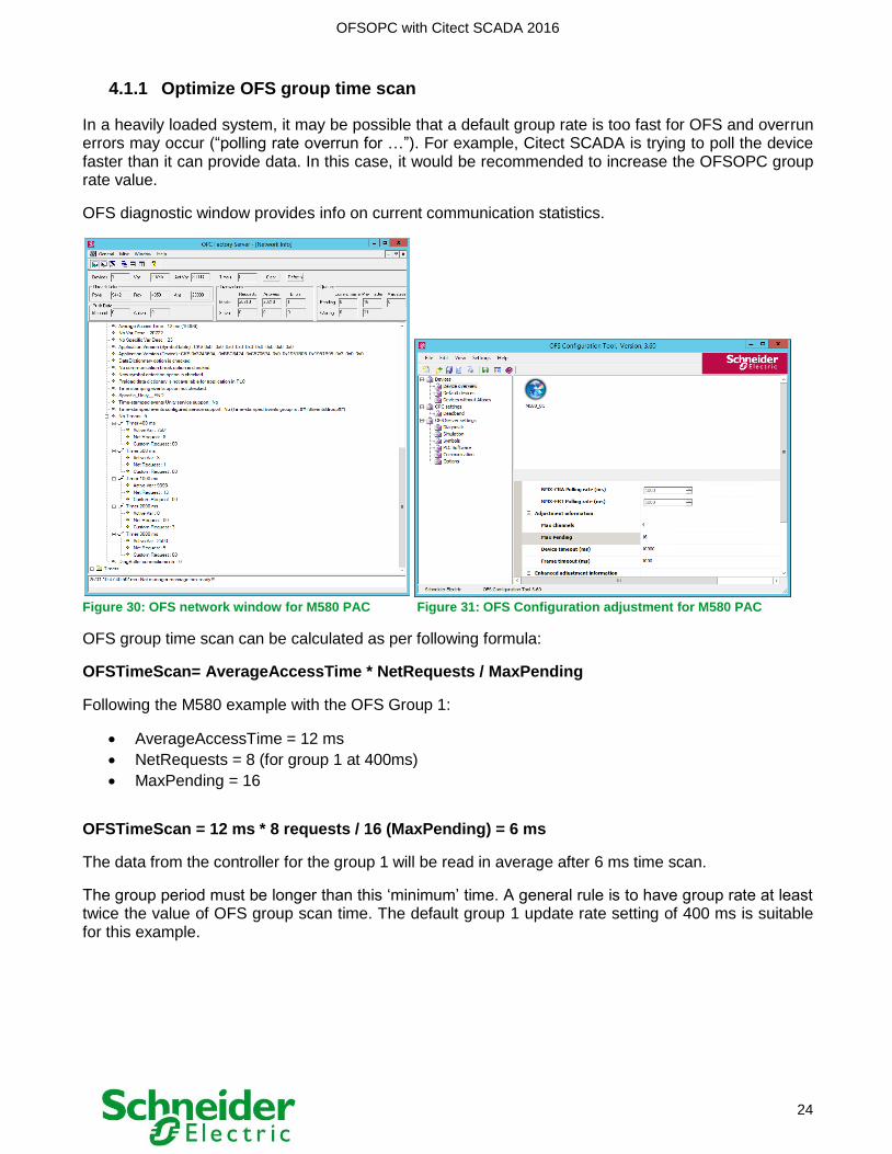
4.1.1 Optimize OFS group time scan
In a heavily loaded system, it may be possible that a default group rate is too fast for OFS and overrun errors may occur (“polling rate overrun for …”). For example, Citect SCADA is trying to poll the device faster than it can provide data. In this case, it would be recommended to increase the OFSOPC group rate value.
OFS diagnostic window provides info on current communication statistics.
Figure 30: OFS network window for M580 PAC Figure 31: OFS Configuration adjustment for M580 PAC
OFS group time scan can be calculated as per following formula:
OFSTimeScan= AverageAccessTime * NetRequests / MaxPending
Following the M580 example with the OFS Group 1:
AverageAccessTime = 12 ms
NetRequests = 8 (for group 1 at 400ms)
MaxPending = 16
OFSTimeScan = 12 ms * 8 requests / 16 (MaxPending) = 6 ms
The data from the controller for the group 1 will be read in average after 6 ms time scan.
The group period must be longer than this ‘minimum’ time. A general rule is to have group rate at least twice the value of OFS group scan time. The default group 1 update rate setting of 400 ms is suitable for this example.

OFSOPC with Citect SCADA 2016
25
4.2 OFS Communication Parameters
When using the OFSOPC driver the following parameters must be activated: Quick Item Validation: An OPC Method is available to validate an item when it is requested from OFS. By default, OFS checks if the value is reachable in the controller and this requires a request to be sent. When Quick Item Validation is enabled, OFS does not run the ‘IsValid’ method. Quick SetActive State: This parameter refreshes the OPC Client as soon as the value is known without waiting for the notification period, as the OPC specification defines. Communication Overrun: This parameter defines whether a communications overrun in OFS should be notified to the SCADA as ‘bad quality’ or if the OFS server should instead try to auto-adapt its own polling rate. It is recommended to set this parameter to ‘rate adapt’ to avoid potential false ‘bad quality’ readings when the load on OFS or the PAC is high.
Select Rate adapt for the Communication Overrun behaviour
Select Quick item validation & Quick SetActive State in Advanced feature.
Enable OPC extensions is mandatory.
Figure 32: Communication windows in OFS configuration
4.3 OFS Options In multi-processor machines it is strongly recommended to set the Processor Affinity of the OFS server such that it does not run on the same processor as the SCADA I/O Server.
Figure 33: Option windows in OFS configuration

OFSOPC with Citect SCADA 2016
26
OFS is set to CPU 0 and Citect processes are set to use other available CPUs.
For the Citect Project, unselect CPU 0 in Setup Wizard in CPU Setup
Figure 34: CPU Setup in Citect Setup Wizard

OFSOPC with Citect SCADA 2016
27
V. Citect SCADA Fast Link
5.1 Import PAC Tags with Fast Link It is possible to import PAC tags into Citect SCADA using the Fast Link feature. If you link to the PAC database, Citect SCADA is updated with any changes made to the PAC when a refresh is performed.
Note: OFS has to be configured and ready to run before importing the PAC tags.
Step 1: Use the Express Communications Wizard to Link your I/O Device to the PAC tag database.
Figure 35: Link I/O Device to the PAC tag database
Step 2: Select Unity SpeedLink to OFS Database type and Browse.

OFSOPC with Citect SCADA 2016
28
Figure 36: Browse external OPC database available
Step 3: Select the PAC branch to import and finalize the express communication wizard procedure.
Figure 37: Complete the Express Communication wizard
You can find the I/O Device configuration in the I/O Devices form in Topology >> IO Devices
Figure 38: I/O Device configuration

OFSOPC with Citect SCADA 2016
29
Refresh tags manually using Refresh tags button in I/O Devices section
Select Automatic Refresh option to True for automatic updates
Figure 39: Refresh Linked Tags
Figure 40: Import Tags

OFSOPC with Citect SCADA 2016
30
5.2 Add / Modify / Delete Tags When Fast Link is used in a Citect SCADA project, if you disconnect an existing link, you can choose to make a local copy of the tags or you can delete them from Citect SCADA's variable tags database altogether.
Use the same methodology to add, modify and delete tag across the PACs and Citect SCADA:
Add/Modify/Delete tag in the PAC
Figure 41: Add Variable tag in Unity Pro
Compile, Download and Run Unity project
Note: OFS has to be configured and ready to run before refreshing the PAC tags.
In Citect SCADA, Refresh tags in Topology view for the selected IO device.
Figure 42: Refresh Linked Tags

OFSOPC with Citect SCADA 2016
31
Figure 43: Import Tags
Tags will be automatically added/modified/deleted in the Citect SCADA variables list
Figure 44: Import Tags
Restart IO Server process to refresh tags in Citect SCADA runtime

OFSOPC with Citect SCADA 2016
32
VI. Performance
6.1 SCADA Redundancy The following tests were performed using Citect SCADA 2016 with the 20,000 IO tag SCADA project ( Project 2) and Schneider PACs.
Time measurements were made by monitoring a trend tag in Process Analyst and using a cicode function to check the connection status of the IO Devices.
Measured startup time to get I/O Device online:
PAC Startup time
M340 9 sec
M580 14 sec
M580 HSBY 16 sec Table 4: Startup time
Note: A registry change was set in Windows on the Citect Server machine to improve redundancy switchover performance in the case of a network isolation.
Add the KeepAliveTime parameter to the
HKEY_LOCAL_MACHINE\SYSTEM\CurrentControlSet\Services\Tcpip\Parameters section with
the value 3000
Figure 45: Registry Editor in Windows
M340 PAC:
Mode of Failure Switchover time
Primary IO Server shutdown 2.0 sec
Primary IO Server interruption (end task) 2.0 sec
Primary IO Server network isolation 13 sec Table 5: Redundancy switchover time with M580 PAC
M580 PAC:
Mode of Failure Switchover time
Primary IO Server shutdown 1.8 sec
Primary IO Server interruption (end task) 2.0 sec
Primary IO Server network isolation 14 sec Table 6: Redundancy switchover time with M580 PAC

OFSOPC with Citect SCADA 2016
33
M580 HSBY PAC: Mode of Failure Switchover time
Primary IO Server shutdown 2.0 sec
Primary IO Server interruption (end task) 2.0 sec
Primary IO Server network isolation 13 sec Table 7: Redundancy switchover time with M580 HSBY PAC
6.2 PAC Redundancy
PAC Hot Standby Switch Over: A failure was simulated on the Primary controller to enable a Hot Standby switchover and check the behaviour of the SCADA system. A Citect Client was displaying tags, alarms and trends properly during and after the PAC Hot Standby switchover. The PAC redundancy switchover worked seamlessly and fast, such that there was no measurable SCADA communications interruption, which was to be expected.
6.3 PAC Scantime The round trip time on the SCADA I/O server was measured to understand the communications performance at the data acquisition layer. This was achieved by sending via cicode a command bit to the PAC, which increments a counter variable and then measuring the time difference for the value to arrive in the I/O server cache. A different PAC scantime was used for each test (see table below). A total of 10 tests were run for each scantime per controller type, with the average and max times recorded. M340 PAC:
CPU Scantime Avg Time (ms) Max Time (ms)
10 518 615 50 600 707 100 678 719
Table 8: M580 PAC round trip time
M580 PAC:
CPU Scantime Avg Time (ms) Max Time (ms)
10 469 511 50 708 869 100 770 856
Table 9: M580 PAC round trip time
M580 HSBY PAC:
CPU Scantime Avg Time (ms) Max Time (ms)
10 481 705 50 574 686 100 709 866
Table 10: M580 PAC round trip time
It can be seen from the above tables that a lower CPU scantime value will have a direct impact on the responsiveness of the SCADA communications.

OFSOPC with Citect SCADA 2016
34
6.1 OFS Server communication modes The OFS Server communication mode is defined by the way in which it accesses the application symbols. The different scenarios to configure OFS Server are:
XVM Symbol table file only
XVM Symbol table file & Using Data Dictionary
Using Data Dictionary only
The following tests were performed using Citect SCADA 2016 with the 20,000 IO tag SCADA project (Project 2) with the Schneider M580 ePAC. Each scenario was tested with the same SCADA system.
Time measurements were made by monitoring a trend tag in Process Analyst and using a cicode function to check the connection status of the IO Devices.
Measured startup time to get I/O Device online:
M580 Startup time
XVM only 11 sec
XVM + Data Dictionary 13 sec
Data Dictionary only 15 sec Table 11: Startup time vs. OFS communication mode

OFSOPC with Citect SCADA 2016
35
Schneider Electric
78 Waterloo Road
Macquarie Park NSW 2113
Phone: + 61 (0) 1300 369 233
www.schneider-electric.com
http://www.schneider-electric.com
http://www.schneider-electric.com April 2017
http://www.schneider-electric.com
© 2
017
Sch
neid
er
Ele
ctr
ic.
All
rig
hts
re
se
rve
d.