Modelling and simulation of process: machine interaction in grinding
10
MACHINE TOOL Modelling and simulation of process: machine interaction in grinding J. C. Aurich D. Biermann H. Blum C. Brecher C. Carstensen B. Denkena F. Klocke M. Kro ¨ger P. Steinmann K. Weinert Received: 28 July 2008 / Accepted: 7 October 2008 / Published online: 15 November 2008 Ó German Academic Society for Production Engineering (WGP) 2008 Abstract This article presents an overview of current simulation methods describing the interaction of grinding process and grinding machine structure, e.g., vibrations, deflections, or thermal deformations. Innovative process models which describe the effects of the grinding wheel– workpiece interaction inside the contact zone are shown in detail. Furthermore, simulation models representing the static and dynamic behaviour of a grinding machine and its components are discussed. Machine tool components with a high influence on the process results are modelled more detailed than those with low influence. The key issue of the paper is the coupling of process and machine tool models for J. C. Aurich Institute for Manufacturing Technology and Production Systems, University of Kaiserslautern, P.O. Box 3049, 67653 Kaiserslautern, Germany e-mail: [email protected] URL: http://www.uni-kl.de/FBK D. Biermann (&) Á K. Weinert Institute of Machining Technology, Dortmund University of Technology, Baroper Str. 301, 44227 Dortmund, Germany e-mail: [email protected] URL: http://www.isf.de K. Weinert e-mail: [email protected] H. Blum Institute of Applied Mathematics, Dortmund University of Technology, Vogelpothsweg 87, 44227 Dortmund, Germany e-mail: [email protected] URL: http://www.mathematik.uni-dortmund.de/lsx C. Brecher Á F. Klocke Laboratory for Machine Tools and Production Engineering, RWTH Aachen University, Steinbachstr. 19, 52074 Aachen, Germany e-mail: [email protected] URL: http://www.wzl.rwth-aachen.de F. Klocke e-mail: [email protected] C. Carstensen Department of Mathematics, Humboldt University Berlin, Unter den Linden 6, 10099 Berlin, Germany e-mail: [email protected] URL: http://www.math.hu-berlin.de B. Denkena Institute of Production Engineering and Machine Tools, Leibniz Universita ¨t Hannover, An der Universita ¨t 2, 30823 Garbsen, Germany e-mail: [email protected] URL: http://www.ifw.uni-hannover.de M. Kro ¨ger Institute of Machine Elements, Design and Production, TU Bergakademie Freiberg, Lampadiusstraße 4, 09596 Freiberg, Germany e-mail: [email protected] URL: http://www.imkf.tu-freiberg.de P. Steinmann Chair of Applied Mechanics, University of Erlangen-Nuremberg, Egerlandstraße 5, 91058 Erlangen, Germany e-mail: [email protected] URL: http://www.ltm.uni-erlangen.de 123 Prod. Eng. Res. Devel. (2009) 3:111–120 DOI 10.1007/s11740-008-0137-x
Transcript of Modelling and simulation of process: machine interaction in grinding

MACHINE TOOL
Modelling and simulation of process: machine interactionin grinding
J. C. Aurich Æ D. Biermann Æ H. Blum Æ C. Brecher ÆC. Carstensen Æ B. Denkena Æ F. Klocke Æ M. Kroger ÆP. Steinmann Æ K. Weinert
Received: 28 July 2008 / Accepted: 7 October 2008 / Published online: 15 November 2008
� German Academic Society for Production Engineering (WGP) 2008
Abstract This article presents an overview of current
simulation methods describing the interaction of grinding
process and grinding machine structure, e.g., vibrations,
deflections, or thermal deformations. Innovative process
models which describe the effects of the grinding wheel–
workpiece interaction inside the contact zone are shown in
detail. Furthermore, simulation models representing the
static and dynamic behaviour of a grinding machine and its
components are discussed. Machine tool components with a
high influence on the process results are modelled more
detailed than those with low influence. The key issue of the
paper is the coupling of process and machine tool models for
J. C. Aurich
Institute for Manufacturing Technology and Production Systems,
University of Kaiserslautern, P.O. Box 3049,
67653 Kaiserslautern, Germany
e-mail: [email protected]
URL: http://www.uni-kl.de/FBK
D. Biermann (&) � K. Weinert
Institute of Machining Technology,
Dortmund University of Technology,
Baroper Str. 301, 44227 Dortmund, Germany
e-mail: [email protected]
URL: http://www.isf.de
K. Weinert
e-mail: [email protected]
H. Blum
Institute of Applied Mathematics,
Dortmund University of Technology,
Vogelpothsweg 87, 44227 Dortmund, Germany
e-mail: [email protected]
URL: http://www.mathematik.uni-dortmund.de/lsx
C. Brecher � F. Klocke
Laboratory for Machine Tools and Production Engineering,
RWTH Aachen University, Steinbachstr. 19,
52074 Aachen, Germany
e-mail: [email protected]
URL: http://www.wzl.rwth-aachen.de
F. Klocke
e-mail: [email protected]
C. Carstensen
Department of Mathematics, Humboldt University Berlin,
Unter den Linden 6, 10099 Berlin, Germany
e-mail: [email protected]
URL: http://www.math.hu-berlin.de
B. Denkena
Institute of Production Engineering and Machine Tools,
Leibniz Universitat Hannover, An der Universitat 2,
30823 Garbsen, Germany
e-mail: [email protected]
URL: http://www.ifw.uni-hannover.de
M. Kroger
Institute of Machine Elements, Design and Production,
TU Bergakademie Freiberg, Lampadiusstraße 4,
09596 Freiberg, Germany
e-mail: [email protected]
URL: http://www.imkf.tu-freiberg.de
P. Steinmann
Chair of Applied Mechanics,
University of Erlangen-Nuremberg, Egerlandstraße 5,
91058 Erlangen, Germany
e-mail: [email protected]
URL: http://www.ltm.uni-erlangen.de
123
Prod. Eng. Res. Devel. (2009) 3:111–120
DOI 10.1007/s11740-008-0137-x
predicting the interactions of process and machine. Several
coupling methods are introduced and the improvements of
the simulation results are documented. On the basis of the
presented simulation approaches, grinding processes and
machines can be designed more effectively resulting in
higher workpiece quality and process stability.
Keywords Process machine interaction � Grinding �Modelling � Simulation
1 Introduction
High quality and high value parts are usually produced in
small lot sizes. Due to the high value of the parts, reject
parts are not acceptable. However, the number of costly
prototypes for identifying reliable process parameters and
tool paths has to be reduced too. Especially grinding pro-
cesses, which are applied as one of the last steps in the
process chain, have to be focused since a process error
during the finishing operations usually leads to high extra
costs. Extensive experimental studies for finding optimal
process parameters are not practicable. Therefore, very
conservative process parameters accounting for long
machining times are normally chosen. An application of
simulation methods which predict the process behaviour
and results during the planning phase would facilitate the
selection of process parameters and increase productivity.
In the past, many approaches for modelling and
simulation of grinding processes were developed and applied
to gain detailed process knowledge. These approaches were
mostly focused on grinding wheel - workpiece interaction.
A comprehensive summary of the state of the art in
simulation of grinding has been given by [1, 2]. Most of the
models are only valid for a specific combination of grinding
wheel, workpiece material, and grinding machine system. In
order to increase the simulation quality, the effect of the
machine tool behaviour during the grinding process has to be
modelled as well. Vibrations and deformations of the
machine structure caused by the process forces can be
determined, which leads to a better predictability of resulting
workpiece geometries and process stability. Strategies can
be derived to reduce geometry as well as thermo mechanical
errors by process parameters and/or tool path optimization,
which are individually adapted to the machine.
This article focuses on modelling of processes and
machines for different grinding kinematics. High-perfor-
mance face grinding, pendulum and speed stroke grinding,
as well as tool grinding, and NC-shape grinding are dis-
cussed as examples. The aim is an exact modelling of the
grinding processes, the surrounding machine structures,
and the interaction effects. In Sects. 2 and 3, several
methods to model both, the grinding process, and the
machine structure are presented. In order to simulate
interaction effects, process and machine models have to be
coupled. Different coupling strategies are discussed in
Sect. 4.
2 Process models
A process model for grinding describes the complex rela-
tionship between process and machine parameters, and
work results. The interaction is modelled by prediction of
grinding forces, temperatures, grinding energies, surface
integrity etc., depending on the process. Multiple approa-
ches for building up a process model are presented in [1].
These include fundamental approaches as well as kine-
matic models, finite element method (FEM), molecular
dynamics, physical and empirical, artificial neural nets, and
rule based models.
This chapter focuses on the prediction of process forces
occurring during grinding as an input value for a machine
model in order to describe the interaction between the
process and the machine structure. Due to the large number
of abrasive grains with an unknown geometry which varies
with time, grinding is a complex material removal opera-
tion [3].
The large number of input variables complicates the
development of a universal model [4]. Due to different
contact conditions, several models have been developed
accounting for different grinding operations.
Kinematic-geometrical simulations are the basis of the
presented process models. Therefore, the penetration
between grinding wheel and workpiece is considered.
Furthermore, these simulations can be distinguished
between microscopic and macroscopic approaches which
are described below. Their complexity and accuracy
depend on the chosen modelling approach and the grinding
process kinematics [1].
20
15
10
5
0
-5
-10
Single grain
Workpiece surface
Com
paris
onst
ress
von
Mie
ses
[N/m
m2 ]
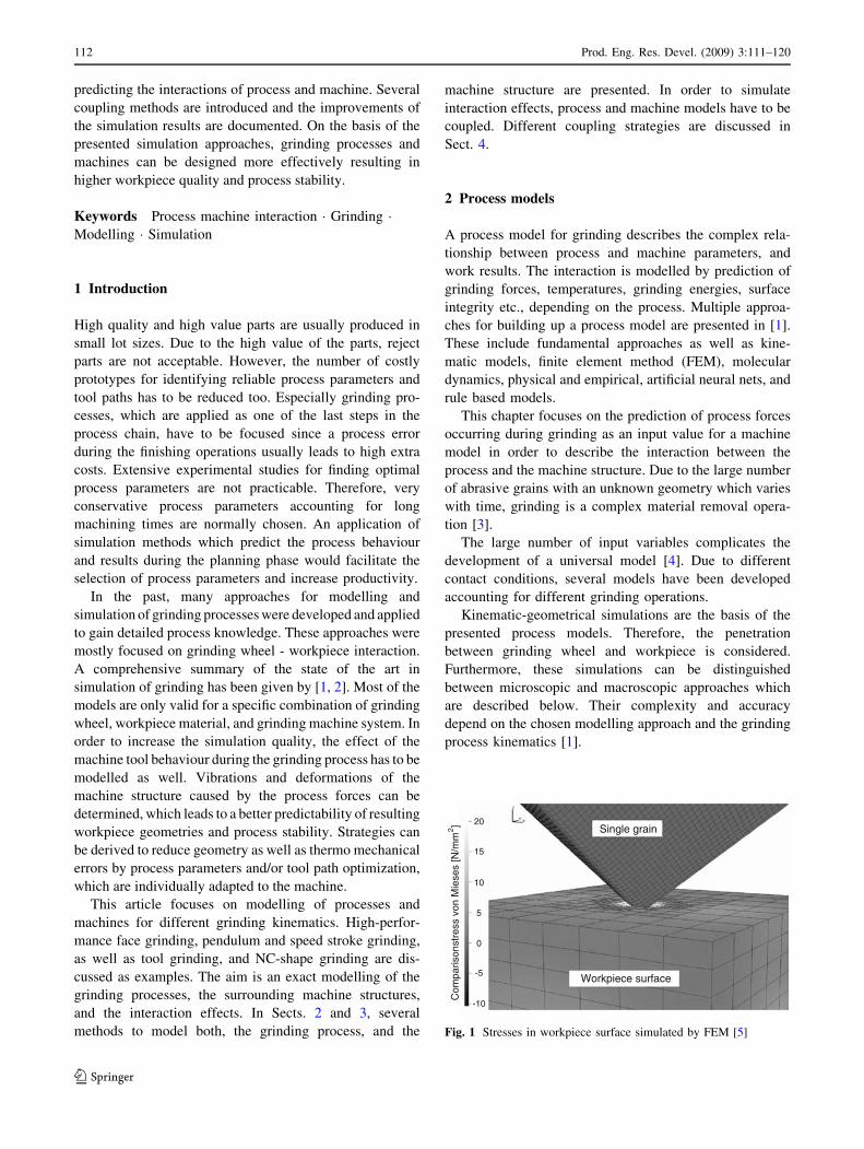
Fig. 1 Stresses in workpiece surface simulated by FEM [5]
112 Prod. Eng. Res. Devel. (2009) 3:111–120
123
2.1 Microscopic approaches
In microscopic approaches, the components participating in
material machining are described in detail. In one
approach, the grinding wheel consists of a detailed
description of the complex 3D shape of each single grain
and its randomly distributed position and orientation on the
wheel, based on statistic functions determined by detailed
statistical analyses of grinding wheel topographies [2].
Other approaches measure the wheel’s topography and use
this data for detailed modelling.
A different microscopic approach is shown in Fig. 1. A
3D FEM simulation model, showing the occurring stresses
during a single grain penetration, is used. The simulation
can be extended by considering multiple statistically dis-
tributed grains to represent grains on certain paths. The
computed stresses of the grains are used to calculate the
process forces.
Based on the knowledge of the grinding wheel topo-
graphy in combination with the process kinematics it is
possible to simulate the machined material by each grain
using a 3D FEM.
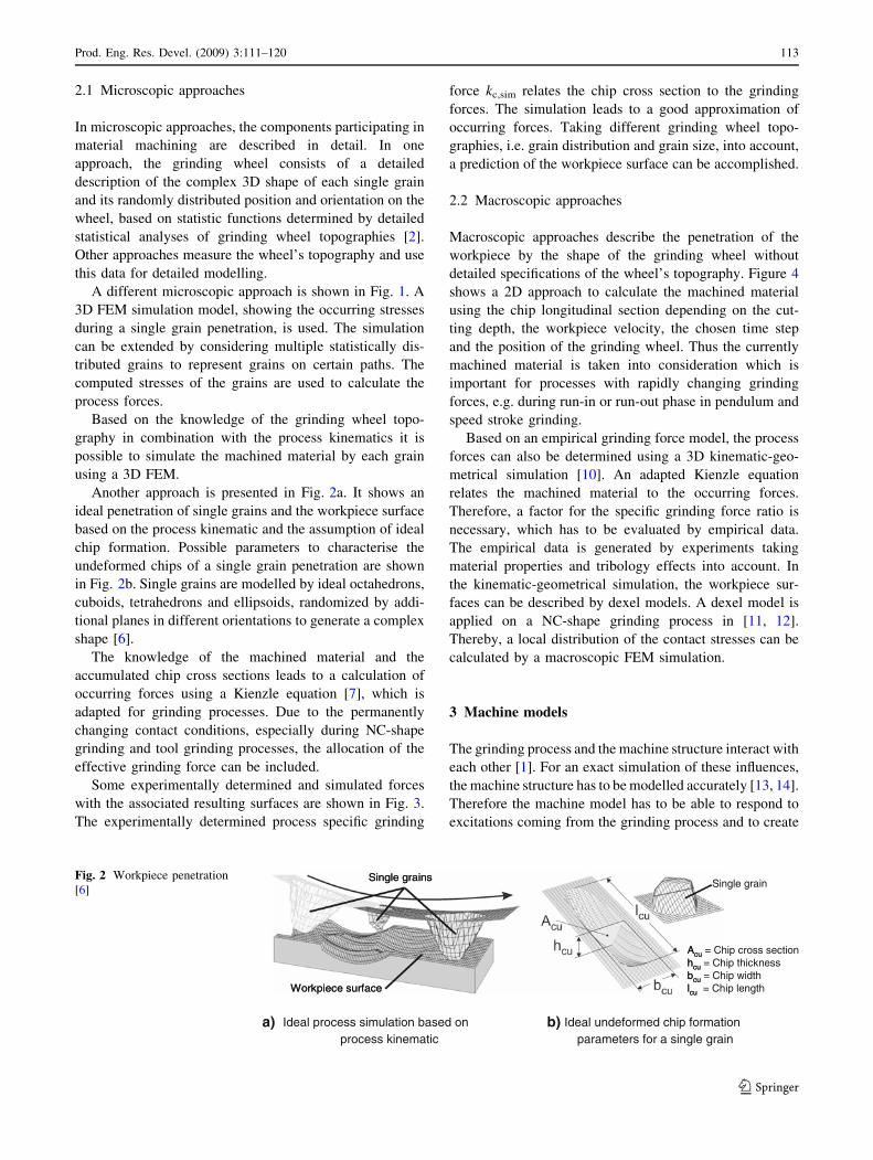
Another approach is presented in Fig. 2a. It shows an
ideal penetration of single grains and the workpiece surface
based on the process kinematic and the assumption of ideal
chip formation. Possible parameters to characterise the
undeformed chips of a single grain penetration are shown
in Fig. 2b. Single grains are modelled by ideal octahedrons,
cuboids, tetrahedrons and ellipsoids, randomized by addi-
tional planes in different orientations to generate a complex
shape [6].
The knowledge of the machined material and the
accumulated chip cross sections leads to a calculation of
occurring forces using a Kienzle equation [7], which is
adapted for grinding processes. Due to the permanently
changing contact conditions, especially during NC-shape
grinding and tool grinding processes, the allocation of the
effective grinding force can be included.
Some experimentally determined and simulated forces
with the associated resulting surfaces are shown in Fig. 3.
The experimentally determined process specific grinding
force kc,sim relates the chip cross section to the grinding
forces. The simulation leads to a good approximation of
occurring forces. Taking different grinding wheel topo-
graphies, i.e. grain distribution and grain size, into account,
a prediction of the workpiece surface can be accomplished.
2.2 Macroscopic approaches
Macroscopic approaches describe the penetration of the
workpiece by the shape of the grinding wheel without
detailed specifications of the wheel’s topography. Figure 4
shows a 2D approach to calculate the machined material
using the chip longitudinal section depending on the cut-
ting depth, the workpiece velocity, the chosen time step
and the position of the grinding wheel. Thus the currently
machined material is taken into consideration which is
important for processes with rapidly changing grinding
forces, e.g. during run-in or run-out phase in pendulum and
speed stroke grinding.
Based on an empirical grinding force model, the process
forces can also be determined using a 3D kinematic-geo-
metrical simulation [10]. An adapted Kienzle equation
relates the machined material to the occurring forces.
Therefore, a factor for the specific grinding force ratio is
necessary, which has to be evaluated by empirical data.
The empirical data is generated by experiments taking
material properties and tribology effects into account. In
the kinematic-geometrical simulation, the workpiece sur-
faces can be described by dexel models. A dexel model is
applied on a NC-shape grinding process in [11, 12].
Thereby, a local distribution of the contact stresses can be
calculated by a macroscopic FEM simulation.
3 Machine models
The grinding process and the machine structure interact with
each other [1]. For an exact simulation of these influences,
the machine structure has to be modelled accurately [13, 14].
Therefore the machine model has to be able to respond to
excitations coming from the grinding process and to create
Workpiece surface
Single grains
Workpiece surface
Single grains
Acuhcubculcu
Acu = Chip cross sectionhcu = Chip thicknessbcu = Chip widthlcu = Chip length
Single grain
Ideal process simulation based on process kinematic
Ideal undeformed chip formation parameters for a single grain
a) b)
Fig. 2 Workpiece penetration
[6]
Prod. Eng. Res. Devel. (2009) 3:111–120 113
123

an output which again has an influence on the calculated
grinding process. Furthermore, the machine model should be
built up as simple as possible to enable an efficient exploi-
tation of the simulation results. Thus, simplifications of the
model, which depend strongly on the considered grinding
process, are required. For error estimation, the machine
models are parameterized by experimental investigations,
like modal analysis or measurements of the damping
behaviour of special machine parts, in general. An exem-
plary grinding machine, which is represented by a machine
model below, is illustrated in Fig. 5.
In this section, different possibilities to model a
grinding machine are presented. Thereby, it has to be
distinguished if the complete machine is modelled in a
full machine model or only special parts of the machine
Fig. 3 Comparison of
measured and simulated process
results [8]
Workpiece
Position: I II III
lg
∆t
Al,total
Grinding Wheel
x1x0
x1x0 x2 x3
Al,totallg
Workpiece
lgAl,total
Grinding Wheel
x1x0
x1x0 x2 x3
Run-in Run-outOverrun
Grinding wheel position
To
tal c
hip
log
itu
din
alse
ctio
n/ A
l,to
tal
: Total chip longitudinal section: Contact length
Fig. 4 Change of chip longitudinal section during face grinding [9]
Ball screws
Machinecontrol
Grinding spindle
Workpiecetable
Guideways
Grinding wheel
Workpiece
Fig. 5 Structure of a grinding machine [15]
114 Prod. Eng. Res. Devel. (2009) 3:111–120
123
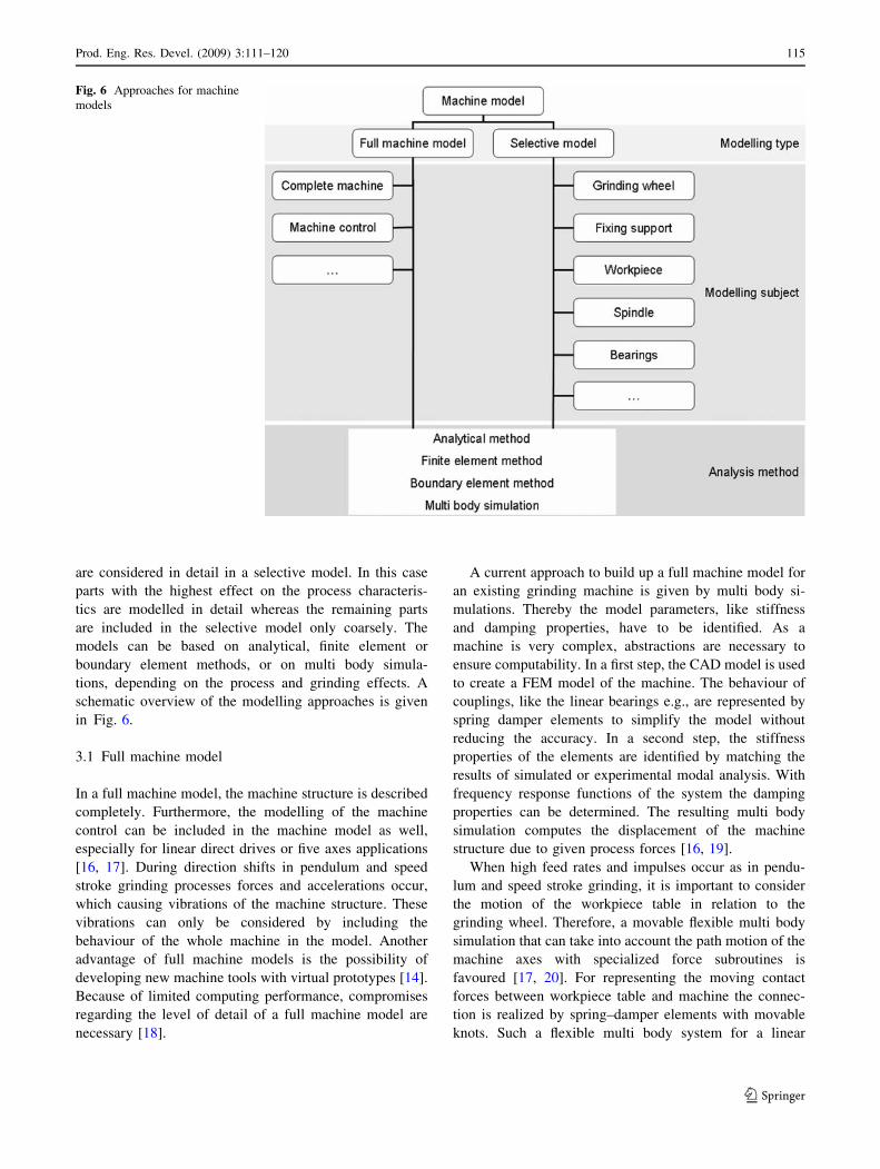
are considered in detail in a selective model. In this case
parts with the highest effect on the process characteris-
tics are modelled in detail whereas the remaining parts
are included in the selective model only coarsely. The
models can be based on analytical, finite element or
boundary element methods, or on multi body simula-
tions, depending on the process and grinding effects. A
schematic overview of the modelling approaches is given
in Fig. 6.
3.1 Full machine model
In a full machine model, the machine structure is described
completely. Furthermore, the modelling of the machine
control can be included in the machine model as well,
especially for linear direct drives or five axes applications
[16, 17]. During direction shifts in pendulum and speed
stroke grinding processes forces and accelerations occur,
which causing vibrations of the machine structure. These
vibrations can only be considered by including the
behaviour of the whole machine in the model. Another
advantage of full machine models is the possibility of
developing new machine tools with virtual prototypes [14].
Because of limited computing performance, compromises
regarding the level of detail of a full machine model are
necessary [18].
A current approach to build up a full machine model for
an existing grinding machine is given by multi body si-
mulations. Thereby the model parameters, like stiffness
and damping properties, have to be identified. As a
machine is very complex, abstractions are necessary to
ensure computability. In a first step, the CAD model is used
to create a FEM model of the machine. The behaviour of
couplings, like the linear bearings e.g., are represented by
spring damper elements to simplify the model without
reducing the accuracy. In a second step, the stiffness
properties of the elements are identified by matching the
results of simulated or experimental modal analysis. With
frequency response functions of the system the damping
properties can be determined. The resulting multi body
simulation computes the displacement of the machine
structure due to given process forces [16, 19].
When high feed rates and impulses occur as in pendu-
lum and speed stroke grinding, it is important to consider
the motion of the workpiece table in relation to the
grinding wheel. Therefore, a movable flexible multi body
simulation that can take into account the path motion of the
machine axes with specialized force subroutines is
favoured [17, 20]. For representing the moving contact
forces between workpiece table and machine the connec-
tion is realized by spring–damper elements with movable
knots. Such a flexible multi body system for a linear
Fig. 6 Approaches for machine
models
Prod. Eng. Res. Devel. (2009) 3:111–120 115
123

bearing of a pendulum grinding machine is pictured in
Fig. 7.
3.2 Selective model
If only some of the machine components react to an
excitation by the grinding process, the machine model can
be focused on these elements by describing them in detail.
The remaining parts are included in the model only coar-
sely and with strong simplifications. Comparing the
selective model with the full machine model, in the
selective model the machine structure is represented with a
higher level of abstraction and only some parts are mo-
delled with more details. Modelling approaches are FEM,
boundary element method, multi body simulations or
analytical models [1, 2]. For parameterising a selective
model, measurements of the real machine are necessary. In
this section, two examples of selective models are pre-
sented, as shown in Figs. 8 and 9.
3.2.1 Spindle and grinding wheel
If the distribution of the process forces depends strongly on
time and space, a detailed representation of the contact area
between grinding wheel and workpiece is needed. This is
the case in high-performance face grinding and, especially,
in NC-shape grinding. One possible approach is to
discretise the grinding wheel with finite elements, which
leads to a well resolved contact surface. This method is
able to include additional effects, like the expansion of the
grinding wheel due to centrifugal forces at high rotational
speed or thermal influences [4].
The behaviour of the whole machine is reduced to
selected parts or assemblies, which decreases the total
modelling effort. One possible representation is to model
an elastic grinding wheel support which includes the
stiffness properties of the grinding machine [22]. Another
possibility is to discretise the spindle with finite elements,
and to concentrate the stiffness of the grinding machine in
elastic bearings [11, 23]. This approach is shown in Fig. 8.
Since the parameters of the bearings cannot be measured
directly, numerical parameter identification techniques are
used to determine them. In this approach, the results of
measurements are compared to corresponding simulation
results. Using optimization algorithms, the optimal
parameters are computed by minimizing the distance
between the measurement and the simulation results.
3.2.2 Workpiece
Grinding processes of very elastic workpieces require a
precise simulation of the process, which can be approxi-
mated by analytical descriptions, FEM, or boundary
element method [1, 2].
Setpath
Actualpath
xz
y
Linear direct drive
Workpiece table
Moving body
Linearguiding
Guiding wagonGuiding wagon
Contactforces
Control loop ZControl loop Y
Control loop X
MBS model Control model
Guiding wagon
Subroutine for Moving contact forces
Fig. 7 Multi body system of a pendulum grinding machine [21]
Fig. 8 Selective model of spindle and grinding wheel based on [11, 23]
Fig. 9 Selective workpiece model based on [25]
116 Prod. Eng. Res. Devel. (2009) 3:111–120
123

For grinding processes of long cantilevering workpieces,
as drills and end mills in the manufacturing state, a beam
model can be used for instance, which is illustrated in
Fig. 9. The machine structure is reduced to the boundary
conditions of the beam model [24]. Parameters for the
elastic and damping properties of the clamping support
have to be identified by measurements of the machine
behaviour, e. g. using modal analysis or structural inves-
tigations [25]. With the parameterized analytical model,
static and dynamic effects of the workpiece are predictable
[5, 25, 26].
4 Coupling of process and machine model
The process and machine models described in the previous
sections need to be coupled in order to simulate the inter-
action between grinding process and grinding machine.
Although coupling problems are also encountered in other
disciplines, such as in fluid-structure interactions or shape
optimisation analyses, this section concentrates only on
some aspects concerning grinding processes. These
aspects, judged to be important for grinding simulations,
have been extracted during studying different works done
in the last years and will be discussed in the following in
detail. Many coupling approaches are based on the
exchange of the grinding forces, as predicted by the process
model, and displacements, as computed by the machine
model, Fig. 10 [5, 26]. Furthermore, heat, temperature and
the shape of the contact area between grinding wheel and
workpiece can be exchanged [27].
The complexity of a process–machine interaction is
determined by the rules according to which the interaction
takes place and the frequency of data exchange between the
process and machine model [28].
Since the process and machine state, in general, vary in
time and additionally involve nonlinearities, the coupling
problem has to be solved iteratively. So, for a certain time
span, during which the process and the machine are con-
sidered, it may be necessary to perform several simulation
iterations. Every time the process and the machine are in an
equilibrium state, the problem is said to be converged for
that iteration and the simulation can proceed to the next
iteration, until the end of the considered time span is
reached. An iterative solution for nonlinear process–
structure coupling problems is presented in [23].
In order to evaluate the process and machine state after
one iteration step, convergence criteria have to be defined.
For a structural analysis, for example, forces or displace-
ments are used as convergence criteria. An overview about
coupling strategies and related convergence problems is for
example given in [11].
In order to obtain accurate simulation results, suffi-
ciently refined time increments and signals are needed. The
Fig. 10 Interaction between
process and machine model
Prod. Eng. Res. Devel. (2009) 3:111–120 117
123

requirement of high accuracy may lead to a large number
of iterations. Thus, the resulting computing time is long.
With some assumptions regarding the process, the
machine, and the interaction, the simulation can sometimes
be simplified. This simplification may lead to a significant
reduction of the computing time, while the simulation
results are still representative for the real process.
The mutual acquisition and transfer of simulation results
between the process and machine model throughout cou-
pling require adequate interfaces. Some interfaces are
offered by commercial software. In other cases, it can be
necessary to implement a self-developed software inter-
face, which is fitted to the process and machine considered.
In [29] interfaces between different grinding simulations
are described.
Through coupling, the accuracy of the simulation results
provided by a non-coupled process and machine model can
be improved. In [23] it is shown how the simulation results
for predicted workpiece topographies can be improved by
taking the interaction between the process and the machine
into account. As shown in Fig. 11, the simulation results
based on coupled process and machine models consider the
influence of the dynamic machine behaviour and, therefore,
match the measured workpiece surface profile more pre-
cisely than the non-coupled solution.
5 Conclusions
Simulation of grinding is still an academic-driven field of
research accounting for many different simulation
approaches which today mainly focus on grinding wheel–
workpiece interaction inside the contact zone. Those sim-
ulations primarily help to increase the understanding of a
grinding process with its millions of single grain engage-
ments resulting in a macroscopic material removal.
This article presents further developments in the field of
modelling and simulation of grinding with the focus on
process–machine interaction. Models describing the
grinding process and models describing the machine
structure are coupled in order to simulate process–machine
interactions. The modelling and simulation is partly done
using commercial software packages. However, in most
cases no appropriate commercial software packages are
available and therefore special software solutions are pro-
grammed. The presented simulation approaches are based
on four different grinding processes, namely face grinding,
speed stroke grinding, tool grinding, and NC-shape grin-
ding. Concerning the process models, macroscopic as well
as microscopic approaches describing the grinding wheel–
workpiece contact are used. Grinding forces are calculated
as input parameters for the machine model. The force
models are mostly based on an adapted Kienzle equation.
For modelling the structure of the grinding machine, those
machine components which cause the main deformations
and displacements between grinding wheel and workpiece
are identified and modelled. Furthermore, the modelling of
the grinding machine strongly depends on the current
process setup, e.g., the grinding kinematics, the material
and shape of workpiece, and the properties of the grinding
wheel.
Within this article different modelling approaches
describing the different components of the grinding
machine are presented. As mentioned, a coupling of
Fig. 11 Simulated and
measured depth of cut of
includes coupled and non-
coupled simulation of process
and machine models [23]
118 Prod. Eng. Res. Devel. (2009) 3:111–120
123

machine and process models is necessary to simulate pro-
cess–machine interactions. Thereby, different coupling
strategies to connect process and machine model have been
discussed. Furthermore, the frequency and amount of data
for the coupling procedures could be varied which influ-
ences the overall simulation result and quality.
The main improvements of coupled simulations are the
more precise prediction of grinding forces and workpiece
topographies, as well as the behaviour of the machine
structure, e.g., deformations and vibrations during the
grinding process. On the one hand, process parameters
optimized for the respective grinding machine can be
identified. On the other hand, tool path optimization and
the identification and improvement of weak points of the
machine structure are possible.
Future research field is the exchange of temperature or
thermal parameters between the process and the machine
model, additionally to the exchange of grinding forces and
deformations within the coupling procedures. Moreover,
CFD simulations for detailed description of the effects
caused by the cooling lubricant can be coupled into the
simulations.
Concerning the software architecture of the coupled
simulations, mostly accounting for several independent
software tools covering the machine and the process,
integral software tools covering both the process and the
machine will be focused in the future.
Acknowledgments This research work was supported by the Ger-
man Research Foundation (Deutsche Forschungsgemeinschaft, DFG)
within the Priority Program 1180 ‘‘Prediction and Manipulation of
Interaction between Structure and Process’’. The authors wish to
express their sincere thanks to further co-workers for their effort in
helping to write this paper, namely A. Bouabid, M. Deichmuller,
M. Duscha, P. Herzenstiel, F. Hoffmann, K. M. Popp, A. Rademacher,
A. V. Scheidler, M. Weiss, and S. Wiedemann.
References
1. Brinksmeier E, Aurich JC, Govekar E, Heinzel C, Hoffmeister
HW, Peters J, Rentsch R, Stephenson DJ, Uhlmann E, Weinert K,
Wittmann M (2006) Advances in modeling and simulation of
grinding processes. Ann CIRP 55(2):667–696
2. Tonshoff HK, Peters J, Inasaki T, Paul T (1992) Modelling and
simulation of grinding processes. Ann CIRP 41(2):677–688
3. Hou ZB, Komanduri R (2003) On the mechanics of the grinding
process—Part 1. Stochastic nature of the grinding process. Int J
Mach Tools Manuf 43:1579–1593. doi:10.1016/S0890-6955
(03)00186-X
4. Mackerle J (2003) Finite element analysis and simulation of
machining: an addendum. A Bibliography (1996–2002). Int J
Mach Tools Manuf 43:103–114. doi:10.1016/S0890-6955
(02)00162-1
5. Denkena B, Tracht K, Deichmuller M (2006) Wechselwirkungen
zwischen Struktur und Prozess beim Werkzeugschleifen. wt
Werkstattstechnik online, Jahrgang 96, H. 11/12
6. Zitt U-R (1999) Modellierung und Simulation von Hochleis-
tungsschleifprozessen. Dissertation, University of Kaiserslautern
7. Kienzle O (1954) Einfluss der Warmebehandlung von Stahlen auf
die Hauptschnittkraft beim Drehen. Stahl Eisen 74:530–551
8. Braun O (2008) Konzept zur Gestaltung und Anwendung
definiert gesetzter CBN Schleifscheiben. Dissertation, Universitat
Kaiserslautern
9. Klocke F, Duscha M, Hoffmann F, Wegner H (2008) Prozess-
Maschine-Wechselwirkung beim Pendel- und Schnellhubschlei-
fen mit hochharten Schleifscheiben. Diamond Buisness
3(2008):52–60
10. Weinert K, Blum H, Jansen T, Mohn T, Rademacher A (2006)
Angepasste Simulationstechnik zur Analyse NC-gesteuerter
Formschleifprozesse. ZWF Zeitschrift fur wirtschaftlichen
Fabrikbetrieb 101(7–8):422–425
11. Weinert K, Blum H, Jansen T, Rademacher A (2007) Simulation
based optimization of the NC-shape grinding process with toroid
grinding wheels. Production engineering—research and devel-
opment. Springer, Berlin, 1/3:245–252
12. Biermann D, Mohn T (2008) A geometric-kinematical approach
for the simulation of complex grinding processes, CIRP Intelli-
gent Computation in Manufacturing Engineering, Innovation and
Cognitive Production Technology and Systems, Naples, Italy
13. Neidhold T, Blochwitz T, Schreiber U (1999) Kooperation von
Simulatoren durch Kopplung. 8. GMM-WS ‘‘Methoden und
Werkzeuge zum Entwurf von Mikrosystemen’’, 2.-3.12. 175–182,
Berlin
14. Altintas Y, Brecher C, Weck M, Witt S (2005) Virtual machine
tool. Ann CIRP. Keynote Pap STC-M 55(2)
15. Source: BLOHM Maschinenbau GmbH, Profimat MT 408 HTS
16. Weck M, Queins Q, Brecher C (2003) Coupled simulation of
control loop and structural dynamics. Ann Ger Acad Soc Prod
Eng X(2):105–110
17. Brecher C, Queins M, Witt S (2004) Coupled simulation of
structural dynamics and control loops for the development of
high-dynamic machine tools. In: Proceedings of NAFEMS
seminar ‘‘Mechatronics in Structural Analysis’’, Wiesbaden
18. Werner K, Klocke F, Brinksmeier E (2003) Modelling and
simulation of grinding processes. In: 1st European conference on
grinding. Aachen, S. 8–1–8–27
19. Queins M (2005), Simulation des dynamischen Verhaltens von
Werkzeugmaschinen mit Hilfe flexibler Mehrkorpermodelle.
Dissertation, RWTH Aachen
20. Hoffmann F, Brecher C (2006) Simulation dynamischer Bahn-
abweichungen von Werkzeugmaschinen. In: Proceedings of VDI
conference ‘‘Elektrisch-mechanische Antriebssysteme’’,
Dusseldorf, VDI
21. Klocke F, Duscha M, Hoffmann F, Wegner H, Zeppenfeld C
(2008) Machine–grinding wheel–workpiece interaction in speed
stroke grinding. In: Proceedings of the 1st international confer-
ence on process machine interaction, pp 259–266
22. Herzenstiel P, Ching CY, Ricker S, Menzel A, Steinmann P,
Aurich JC (2007) Interaction of process and machine during high-
performance grinding—towards a comprehensive simulation
concept. Int J Manuf Technol Manage 12(1/2/3):155–170
23. Jansen T (2007) Entwicklung einer Simulation fur den
NC-Formschleifprozess mit Torusschleifscheiben. Dissertation,
Technische Universitat Dortmund, Essen, Band 43
24. Denkena B, Deichmueller M, Kroeger M, Panning L, Carstensen
C, Kilian S (2007) Modeling and simulation of the process
machine interaction during tool grinding processes. In: Proceed-
ings of the 10th CIRP international workshop on modelling of
machining operations, 27–28.8.2007, Reggio Calabria, Italy
25. Popp KM, Kroger M, Deichmueller M, Denkena B (2008)
Analysis of the machine structure and dynamic response of a tool
Prod. Eng. Res. Devel. (2009) 3:111–120 119
123

grinding machine. In: Proceedings of the 1st international con-
ference on process machine interaction, pp 299–307
26. Denkena B, Deichmueller M, Kroger M, Popp KM, Carstensen C,
Schroeder A, Wiedemann S (2008) Geometrical analysis of the
complex contact area for modeling the local distribution of pro-
cess forces in tool grinding. In: Proceedings of the 1st
international conference on process machine interaction, pp 289–
298
27. Malkin S, Guo C (2007) Thermal analysis of grinding. CIRP Ann
Manuf Technol 56(2):760–782
28. Herzenstiel P, Bouabid A, Steinmann P, Aurich JC (2008)
Experimental investigation and computational simulation of
process–machine interactions during high-performance surface
grinding. In: Proceedings of the 1st international conference on
process machine interaction, pp 267–278
29. Weinert K, Blum H, Jansen T, Mohn T, Noyen M, Rademacher A
(2007) Verfahrensspezifische Modellbildung fur die Belastung
beim Schleifen. In: Hoffmeister H-W, Denkena B: Jahrbuch
Schleifen, Honen, Lappen und Polieren, Vulkan-Verlag, Essen,
63:24–38
120 Prod. Eng. Res. Devel. (2009) 3:111–120
123