
Variability studies for the Sossego 41 ktpd grinding circuit
19
VARIABILITY STUDIES FOR THE SOSSEGO 41 KTPD GRINDING CIRCUIT By M. Bergerman, H. Delboni, J. Morais, A. Castro and M. Nankran Contact author: Mr. Mauricio Bergerman Vale – Department of copper, Rua Grajau, 63, Parauapebas, PA, 68516-000. Brasil Tel: (55 94) 3327-2314 Email: [email protected] Dr. Homero Delboni University of Sao Paulo, Avenida Prof. Mello Moraes, 2373 São Paulo SP, 05508-900 Brasil Email: [email protected] Mr. Juarez Morais Vale – Department of copper, Rua Grajau, 63, Parauapebas, PA, 68516-000. Brasil Email: [email protected] Mr. Adilson Castro Vale – Department of copper, Rua Grajau, 63, Parauapebas, PA, 68516-000. Brasil Email: [email protected]
Transcript of Variability studies for the Sossego 41 ktpd grinding circuit

VARIABILITY STUDIES FOR THE SOSSEGO 41 KTPD
GRINDING CIRCUIT By
M. Bergerman, H. Delboni, J. Morais, A. Castro and M.
Nankran
Contact author: Mr. Mauricio Bergerman Vale – Department of copper, Rua Grajau, 63, Parauapebas, PA, 68516-000. Brasil Tel: (55 94) 3327-2314 Email: [email protected] Dr. Homero Delboni University of Sao Paulo, Avenida Prof. Mello Moraes, 2373 São Paulo SP, 05508-900 Brasil Email: [email protected] Mr. Juarez Morais Vale – Department of copper, Rua Grajau, 63, Parauapebas, PA, 68516-000. Brasil Email: [email protected] Mr. Adilson Castro Vale – Department of copper, Rua Grajau, 63, Parauapebas, PA, 68516-000. Brasil Email: [email protected]

Mr. Marco Nankran Vale – Department of copper, Rua Grajau, 63, Parauapebas, PA, 68516-000. Brasil Email: [email protected]

Variability studies for the Sossego 41 ktpd grinding circuit
By M. Bergerman, H. Delboni, J. Morais, A. Castro and M. Nankran
ABSTRACT
Sossego was the first Vale SAG mill operation to process copper-gold ore. It is located in Para state, south east of Amazon region in Brazil. The comminution circuit was designed to treat 41 000 metric tons per day comprising primary crushing, one 11.6 m SAG mill operating in closed configuration with cone crushers, followed by two 6.7 ball mills. In the first three years of continuous operation Vale investigated alternatives for obtained improved performance of the circuit by investigating operating conditions, mainly focusing on SAG mill. A number of actions were then implemented, which resulted in significant increase in overall production. Vale then decided to further assess the performance of the comminution circuit as a function of ore characteristics. A comprehensive ore characterization program was then conducted, together with the calibration of mathematical models on the basis of surveys carried out at the industrial circuit. The simulator was then used to predict the production level associated to each ore type, as well as to establish the optimized circuit configuration and tailored operating conditions. The ongoing validation program is planned to consolidate the selected strategy, as well as showing the benefits in adopting such indices in mine planning, as opposed to rather simplistic approaches. This paper describes in detail the main aspects of optimizing the industrial circuit performance, as well as the successful method for predicting the production as a function of ore characteristics. Key words: copper, grinding, simulation, variability, blasting

INTRODUCTION Sossego is the first Vale project in copper business. It is based on a copper-gold resource discovered in early 1997 comprising Sequeirinho and Sossego adjacent ore bodies.
The mine is situated approximately 70 km south-west of Carajas area, near the town of Canaa dos Carajas, in the south of Para state, Brazil. The concentrator was designed to process 41 000 metric tons per day which is equivalent to 15 million metric tons per year from an open pit mine. The proved reserve is 255 Mt with an average grade of 1.0% Cu and 0.3 g/t Au. The ore is a granite with significant occurrence of magnetite. Typical Bond ball mMill Work Index (BWI) varies from 17 to 20 kWh/t, as well as relatively high Abrasion Index (0.5). Operation of Sossego mine and processing plant started in April 2004 targeting an average concentrate production of 540 000 metric tons per year with 30% Cu and 8 g/t Au. Industrial Circuit Sossego industrial plant comprises a typical high-tonnage primary crushing-SABC-flotation circuit based on large capacity equipment in each unit operation. A brief description of Sossego circuit follows. Primary crushing
Run-of-Mine ore is delivered to a 6089 gyratory crusher by 240 ton rear-dump trucks. The primary crusher operates under nominal closed side setting of 139.7 mm which results in a product P80 of 125 - 150 mm. Crushed ore is conveyed to a conical pile adjacent to the concentrator by a 4 km long conveyor belt, which operates at a nominal rate of 2300 t/h. Crushed ore stockpile
The conical ore stockpile has a live capacity of 41 kt, equivalent to 24 h of plant operation. Three tandem apron feeders are located underneath the stockpile feeding a single conveyor belt that supplies the SAG mill.

Grinding
The grinding circuit consists of a single line configured as SABC with a nominal capacity of 1841 t/h. A 11.6 diameter by 7 m (EGL) SAG mill is driven by a 20 MW gearless motor. The SAG mill discharges onto two 3.6 x 7.3 m horizontal vibrating screens whose oversize is conveyed to the recycle crushing building where two conical crushers reduces the pebbles to a nominal P80 of 12 mm. The crushed product is conducted back to the SAG mill feed, therefore closing the circuit. The screen undersize is pumped to two separated nests of 0.8 m hydrocyclones. Each nest underflow is directed to one of the two 6.7 x 9.7 m ball mill, equipped with 8,5 MW motor single pinion fixed speed drive. Targeted P80 of hydrocyclone overflow is 0.21 mm at 40% solids. Flotation and Regrinding
The hydrocyclone overflow from each ball mill circuit feeds the rougher stage consisting of seven 160 m³ tank cells. Rougher tailings from both lines are sent by gravity to the tailing dam. Rougher concentrates are pumped to the regrind circuit consisting of two vertical mills (1500 hp motor each) operating in a reverse mode with 0.38 m hydrocyclones. The regrind circuit product, with a nominal P80 of 0.044 mm is pumped to the six cleaner flotation columns (4.27 x 10 m). The column tails feed the cleaner-scavenger cells ie. one row of seven 70 m³ cells. The cleaner-scavenger concentrate is combined with the rougher concentrate, thus forming the circulating load of the flotation circuit. The cleaner-scavenger tails are pumped to the tailing dam, whereas the cleaner concentrate is pumped to a thickener. Thickening and filtering
Final concentrate flows by gravity to a 20 m diameter thickener. The thickener overflow is recycled to the flotation feed and the underflow is pumped at 60% solids to the filtering plant tanks. From the filtering feed tank concentrate is pumped to two filters. The filtrate returns to the thickener and the cake with 9% moisture is stocked in a 5250 t capacity conical pile, located in a moisture controlled building. The concentrate is reclaimed by front end loaders to 35 t haul trucks which dump it in a storage building in the city of Parauapebas. From Parauapebas the concentrate is then transported by a 800 km railway to the port of Itaqui, in Maranhao state, from where it is shipped to various costumers, located at Brazil, Korea, Bulgaria, Germany, China, Sweden, Indian, Japan and the Philippines.
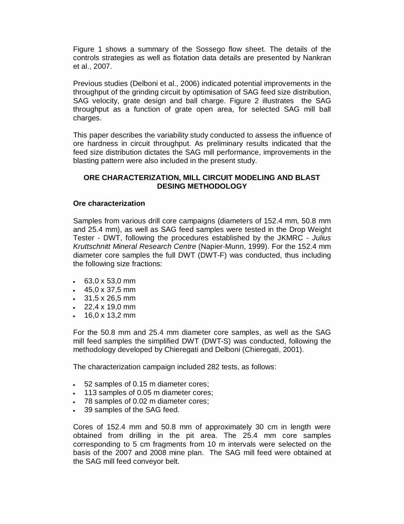
Figure 1 shows a summary of the Sossego flow sheet. The details of the controls strategies as well as flotation data details are presented by Nankran et al., 2007. Previous studies (Delboni et al., 2006) indicated potential improvements in the throughput of the grinding circuit by optimisation of SAG feed size distribution, SAG velocity, grate design and ball charge. Figure 2 illustrates the SAG throughput as a function of grate open area, for selected SAG mill ball charges. This paper describes the variability study conducted to assess the influence of ore hardness in circuit throughput. As preliminary results indicated that the feed size distribution dictates the SAG mill performance, improvements in the blasting pattern were also included in the present study.
ORE CHARACTERIZATION, MILL CIRCUIT MODELING AND BLAST
DESING METHODOLOGY Ore characterization Samples from various drill core campaigns (diameters of 152.4 mm, 50.8 mm and 25.4 mm), as well as SAG feed samples were tested in the Drop Weight Tester - DWT, following the procedures established by the JKMRC - Julius Kruttschnitt Mineral Research Centre (Napier-Munn, 1999). For the 152.4 mm diameter core samples the full DWT (DWT-F) was conducted, thus including the following size fractions: 63,0 x 53,0 mm 45,0 x 37,5 mm 31,5 x 26,5 mm 22,4 x 19,0 mm 16,0 x 13,2 mm For the 50.8 mm and 25.4 mm diameter core samples, as well as the SAG mill feed samples the simplified DWT (DWT-S) was conducted, following the methodology developed by Chieregati and Delboni (Chieregati, 2001). The characterization campaign included 282 tests, as follows: 52 samples of 0.15 m diameter cores; 113 samples of 0.05 m diameter cores; 78 samples of 0.02 m diameter cores; 39 samples of the SAG feed. Cores of 152.4 mm and 50.8 mm of approximately 30 cm in length were obtained from drilling in the pit area. The 25.4 mm core samples corresponding to 5 cm fragments from 10 m intervals were selected on the basis of the 2007 and 2008 mine plan. The SAG mill feed were obtained at the SAG mill feed conveyor belt.

Mill circuit modelling The experimental basis for modelling the grinding circuit comprised survey campaigns, following the protocols described by Napier-Munn et al. (1999). Prior to sampling, operating conditions were checked to ensure that the plant was operating under steady-state conditions. Two survey campaigns were carried out, the first in 2006 and the second in 2007. During a period of two hours 9 streams were sampled incrementally. Previous calculations indicated the minimum amount of sample to be taken in each sampling point. The following streams were sampled: SAG mill feed; SAG screen oversize (pebbles crusher feed); Pebble crusher product; Cyclone feed; Cyclone overflow and flotation feed (back up and comparison); Cyclone underflow and ball mill feed (back up and comparison); Ball mill product. Due to its lay-out, the SAG mill screen undersize is practically impossible to be correctly sampled. Solids and water flowrates of such a stream was therefore later estimated by mass balance calculations. Immediately after the sampling period the SAG mill was crash stopped by simultaneously shutting down the feeding conveyor belt, the mill water flow valve and the mill. After removing the feed chute the charge level and mill internal dimensions were measured. A period of grind-out followed for later measuring the remaining ball charge in the SAG mill. Both ball mill and cyclone dimensions were taken during a plant maintenance shutdown, which occurred two days before the sampling campaign. The nine samples were analysed at the process laboratory located in the industrial plant. They were weighted, filtered and dried, then screened for size analysis at screen of 203, 152, 127, 100, 76.2, 50, 37.5, 25, 19, 12.5, 9.5, 6.3, 4.75, 3.3.5, 2, 1, 0.5, 0.425, 0.3, 0.212, 0.150, 0.106, 0.075, 0.053 and 0.038 mm. Sample from the SAG feed was tested for DWT, abrasion and Bond Work Index. The experimental data base for each survey also included information from the supervisory system installed at Sossego control room. These comprised SAG mill feed flow rate, power draw, load cell indication, water flow rate, mill speed, screen oversize and recycle crusher flow rates, cyclone pressure, percent solids, circulating load, number of cyclones in operation, ball mill power draw, final product size distribution and percent solids. Auxiliary information as stockpile hight, feeders in operation, silo levels and sump levels were also recorded during the sampling period.

Raw data were mass balanced using the mass-balancing algorithm of JKSimMet version 5.1 (JKTech Pty Ltd., Queensland, Australia). After the mass balancing models of JKSimMet were fitted. The following models were used: SAG mill; Pebble crusher; SAG screen; Cyclones; Ball mill. Once fitted individually the models were integrated into a single flow sheet that included both primary and secondary grinding circuits. Adjusts were particularly necessary at the SAG screen undersize flow, as it links both circuits but no experimental data was obtained. Once calibrated for both surveys several alternatives for circuit optimization were evaluated in order to have a sensitive analysis for each main operating variable of the circuit. The following optimisation strategies were analysed: Secondary crushing of the – 0.127 + 76.2 mm primary crusher product; Opening of the pebble crusher circuit; Change at the SAG screen aperture (from 13 to 19 mm); Cyclone geometry; Changes in ore hardness; Changes in feed size; Changes in SAG ball size; Changes in ball mill ball size. Blasting improvement Simulations of the muck pile size distribution were carried out by using the Two Component Model (TCM), as developed by Djordjevic (1999), as well as the Kuz-Ram model, developed by Kusnetzov (1973). Table 1 describes the blast design parameters and explosive properties used for the test.
RESULTS AND DISCUSSION Ore characterization DWT-S tests generally result in lower A*b values than the corresponding figures obtained for the full DWT (DWT-F). This is due to the fact that the finer the fragment the more resistant it becomes. Accordingly, relatively coarser fragments contain relatively more flaws, natural weakness planes, blasting inducted cracks than the finer fragments as resulting from comminution in the sample preparation processes. Therefore it is necessary to calculate the equivalent A*b for DWT-F on the basis of DWT-S results. This is carried out by assessing the A*b figures

obtained for samples tested on both DWT-F and DWT-S. Such a procedure was carried out for tests conducted on 152.4 mm, 50.8 mm and 25.4 mm core samples. Figure 3 illustrates the results of the DWT tests with correspondent calculations. It is clear that the 50.8 mm and 152.4 mm samples are more heterogeneous than the 25.4 mm and SAG feed. Analysis of drill core description indicated that some samples included pure chalcopyrite fragments, which explains the relatively low resistance values indicated in the 25.4 mm core sample distribution. The 25.4 mm and SAG feed samples showed homogeneous distributions. It is also interesting to observe that the SAG mill feed samples are relatively harder than the other groups. It suggests that the ore variability is not the main factor that influences the variations in the SAG mill throughput. Mill circuit modelling In general mass balancing procedures indicated good data quality, as assessed by the errors calculated for flow rates and size distributions around classification equipment. The mass balanced data provided very good fit to the selected models, thus indicating overall good quality of the experimental work. Table 2 lists relevant experimental data obtained after model fitting exercises. Figures 4 and 5 illustrate the results of experimental data, balanced data and model fitted data.
It is interesting to note that in one of the surveys the SAG mill was running at 67% of its critical speed, while it usually runs at 80% of the critical speed. This is due the fact that the feed F80 was around 88.9 mm, therefore very fine as compared with the usual value of 127 mm. The derived model covers therefore a relatively wide range of mill speed operation and feed size distribution, as the second survey was conducted under usual operating conditions. A robust SAG mill model was thus obtained. Another remarkable aspect of the circuit is the amount of fines at the screen undersize stream. The minus 0.210 mm fraction accounted for approximately 60% of the total mass at this point, thus ready for the flotation stage. This illustrates the massive amount of fines generated by the SAG mill. Based on the calibrated model a number of simulations were carried out to assess the impact of individual operating variables in the circuit throughput. A summary follows: Secondary crushing of the – 127 + 76.2 mm primary crusher product:
throughput increases in the range of 13 to 29%; Change at the SAG screen aperture (from 13 to 19 mm): decrease in the
circulating load of the pebble crusher from 19 to 25%;

Opening of the pebble crusher circuit: increase in throughput of 2% or higher depending upon the ore type;
Cyclone geometry: a coarser flotation feed resulted in significant reduction in the ball mill circulating load;
Change in ore hardness: variation of 6% in throughput for the 2008 mine plan;
Change in feed size (F80 from 139.7 mm to 114.3 mm): increase in throughput of 10%;
Change in SAG ball size: increase 8% in throughput; Change in ball mill ball size: coarser flotation feed F80 of 10%. Some of these alternatives were implemented at the plant, while others are planned for future implementation. For the ones that are already implemented it was possible to validate the model used. The following were observed: Opening of the pebble crusher circuit resulted in up to 10% increase in
throughput for certain ore types (Nankran et al., 2007); Cyclone geometry: similar F80 results to those simulated were obtained; Change in ore hardness: good adherence between simulations and actual
plant data; Change in SAG mill feed size distribution: recent tests indicated a 10%
increase in plant throughput, thus confirming the simulations. Changes in ball sizes were also implemented but evaluating its effects were not possible, as other changes were simultaneously in place, such as changes in grate aperture (Delboni et al., 2006). Simulations also indicated the benefits of using the recycled SAG mill 101.6 mm balls in the ball mills. This action, together with changes at the cyclone geometry helped in reducing the ball mill circulating load, which thus improved the metallurgical recovery of copper. This is explained by the fact that high losses of chalcopyrite flotation are associated to fines and previously 30% of the contained copper in the flotation feed was within the minus 8 m fraction, while only 4% at the + 0.210 mm. A more adequate size distribution obtained by coarser ball sizes resulted in approximately 1% increase in copper recovery. Blasting improvement The effects of different blasting patterns in SAG mill F80 are illustrated in Figure 6. It shows consistent the reduction in the F80 of the SAG mill feed, while the primary crusher closed size setting was kept constant.
Figure 7 illustrates the stockpile before and after the test. It is clear the increase of fines. The reduction of the feed size illustrated at Figure 6 resulted in SAG mill throughput of 10%. Accordingly, the SAG mill throughput increase in 10% as its feed F80 was changed from 114.3 mm to 88.9 mm. Besides the benefits in throughput it was also observed higher productivity associated to the front-end-loaders at the mine. Furthermore, there was a

lower consumption of wear materials in the mine and in the mill, as well as a higher availability of the primary crusher. The latter was a direct consequence of reducing the frequency of oversized rocks in the primary crusher chamber. The increase associated with a higher fragmentation (higher powder factor and drilling) was in the order of half of the earns resulting from the increase in the grinding circuit throughput. Even though not quantified, other earns were associated with higher mine productivity and lower maintenance costs. It was clear thus that the mine to mill approach has a potential for increasing the overall production with lower costs.
CONCLUSIONS
A comprehensive experimental data base was established for assessing both ore characteristics and circuit performance of Sossego industrial grinding plant. Ore characteristics showed relatively homogeneous distributions for different drill core campaigns, as well as for testing resulted from samples obtained from the SAG mill feed. Surveys carried out at the Sossego industrial plant indicated on average good quality of data which were reflected on excellent model fitting exercises. The obtained model was considered robust enough for simulating the integrated grinding circuit. Simulations conducted to assess the circuit performance as a function of individual operating conditions indicated a number of potential modifications which resulted in improved overall performance. Accordingly, simulations were useful to identify, quantify and determine in detail the potential for improving the Sossego production. One of the most important variables selected in the simulations was the SAG mill size distributions, while ore characteristics was considered of a minor influence in circuit performance. The latter thus reflects the small variations obtained in the testing campaign. Selected modifications were progressively implemented to the industrial circuit showing very good adherence to the corresponding simulations, such as opening the recycle crusher circuit and changes in the hydrocyclone geometry. Implementation of tailored blasting patterns resulted in higher fragmentation, which in turn significantly increased the SAG mill throughput, as previewed by simulations.
REFERENCES
Chieregati, A.C.; 2001. New method for the technological characterization of ores to comminution, Masters in engineering thesis (unpublished), University of Sao Paulo, Sao Paulo (in Portuguese).

Delboni, H, 2004, Assessment and Optimization of the Sossego Grinding Circuit. Report (in Portuguese). Delboni, H, Rosa, M, Bergerman, M, Nardi, R. 2006. Optimisation of the Sossego SAG Mill. Advances in autogenous and semi autogenous grinding technology, Vancouver. p. I39-I50. 1 CD-ROM. Djordjevic, N. 1999. A Two-Component Model of Blast Fragmentation. The AusIMM Proceedings, Brisbane, Australia. p. 9 – 13. Kuznetsov, V. 1973. The mean diameter of the fragments formed by blasting rock. Soviet Mining Science. p. 144-148. Morais, J. 2004. Simulation of the fragmentation of rock blasting with explosives. PhD thesis (unplublished), Federal University of Minas Gerais, Belo Horizonte (in Portuguese). Nankran, M, Bergerman, M, Fonseca, R, Queiroz, A, Geraldo, J. 2007. Opening of the Sossego SAG mill circuit, XXII National Ore Treatment Meeting, Ouro Preto, Brazil. (In Portuguese) Nankran, M, Bergerman, M, Miranda, A, Oliveira, J, Souza, M, Batista Filho, J, Cardoso, W. 2007. Operational control of the Sossego metallurgical plant, XXII National Ore Treatment Meeting, Ouro Preto, Brazil. (In Portuguese)
Napier-Munn, T.J. et al. 1999. Mineral comminution circuits: their operation and optimization. Indooroopilly: Julius Kruttschnitt Mineral Research Centre/University of Queensland (JKMRC Monograph Series in Mining and Mineral Processing).
ACKNOWLEDGEMENTS
The authors whish to thanks Vale for the support and permission to publish this paper.

LIST OF HEADINGS
INTRODUCTION
Industrial circuit
Primary crushing
Crushed ore stockpile
Grinding
Flotation and Regrinding
Thickening and filtering
ORE CHARACTERIZATION AND MILL CIRCUIT MODELING METHODOLOGY
Ore characterization
Mill circuit modelling
Blasting improvement
RESULTS AND DISCUSSION
Ore characterization
Mill circuit modelling
Blasting improvement
CONCLUSIONS REFERENCES

CAPTIONS
Table captions
Table 1. Blast design parameters and explosive properties for the test.
Table 2. Planta data
Figure captions Figure 1. Sossego flow sheet.
Figure 2. SAG mill throughput as a function of grate open area and ball
charge.
Figure 3. DWT distributions.
Figure 4. Full size distribution comparison.
Figure 5. Circuit data – experimental vs. model fit.
Figure 6. SAG mill F80 for different blast designs
Figure 7. Stock pile after and before the blasting pattern change

TABLE 1
Blast design parameters and explosive properties for the tests.
Blasting parameters Old New Hole diameter (mm) 311 311 Spacing (m) 8,5 6,6 Burder (m) 6,5 5,7 Spacing x burder (m) 55,3 36,8 Bench height (m) 16 16 Staimming (m) 6 6,1 Subdrill (m) 2 2 Rock density (g/cm3) 2,85 2,85 Rock factor 6 6 Linear powder factor (kg/m) 90 90 Rock mass per hole (t) 2652 1709 Explosive mass per hole (kg) 1.080 1.070 Powder factor (g/t) 407 626
Explosive tipe Heavy ANFO
Heavy ANFO
X50 (cm) 19,6 14,2 Crushing zone diameter (m) 1,5 1,5 Fines at the pulverize zone (%<50mm) 3,2 4,8
TABLE 2 Plant data
SAG mill Pebble crusher Cyclones Diameter (inside liners) (m) 11.4 Closed Side Setting - CSS (mm) 15 Parameter
Belly length (inside liners) (m) 6.82 Measured Power Draw (kW) 360 Cyclone Diameter - Dc (m) 0.838
Feed trunion diameter (m) 2.28 Measured No Load Power (kW) 240 Inlet Diameter - Di (m) 0.25 Grate Size, xg (mm) 74.16 Vortex Finder Diameter - Do (m) 0.375
Fine Size, xm (mm) 1.059 Ball mill Spigot Diameter - Du (m) 0.175
Grate Open Area fraction 0.0948 Original Mill Cylinder Length - Lc (m) 0.7
Ball Load (%by vol) 14.5 Internal diameter (m) 6.52 Cone Angle - Theta (deg) 20
Ball Top Size (mm) 133 Internal length (m) 9.42 Water Split To O/F (%) 69
Impact Breakage Fraction Critical Speed 0.75 Operating Pressure, kPa 65 Parameter A 63.2 Load Fraction 0.3 N. of ciclones 6
Parameter B 0.5 Ore Work Index (kWh/t) 17
Abrasion ta 0.224 Original Mill Ball Top Size (mm) 76 Calculated Ecs
Fraction critical speed 0.67 SAG screen
Ball specific gravity 7.8 First deck 25.4 mm
Measured Power (kW) 15 500 Second deck 13 mm
Exp Volumetric total load (%) 30

FIG 1 – Sossego flow sheet.
FIG 2 – SAG mill throughput as a function of grate open area and ball charge.
1100
1200
1300
1400
1500
1600
1700
1800
1900
8.0 8.5 9.0 9.5 10.0 10.5 11.0
Grate open area (%)
SAG
mill
thro
ughp
ut (t
/h)
8% Ball Charge
10% Ball Charge
13.5% Ball Charge

FIG 3 – DWT distributions
S AG fedd
0102030405060708090
100
0,00 0,01 0,10 1,00 10,00 100,00 1000,00Size (m m )
Cum
ulat
ive
pass
ing
(%)
exper imental balanced model f it
Oversize of the SAG screen
0102030405060708090
100
10,00 100,00 1000,00Siz e (m m )
Cum
ulat
ive
pass
ing
(%)
exper imental balanc ed model f it
U n d ersiz e of th e S AG s cre en
01020
3040506070
8090
100
0,00 0,01 0,10 1,00 10,00 100,00 1000,00Siz e (m m )
Cum
ulat
ive
pass
ing
(%)
ex per imental balanc ed model f it
Pebble crusher product
01020
3040506070
8090
100
0,10 1,00 10,00 100,00 1000,00s iz e (m m )
Cum
ulat
ive
pass
ing
(%)
experimental balanc ed model f it
0
10
20
30
40
50
60
70
80
90
100
0 20 40 60 80 100 120 140 160 180 200A*b
Acum
ulat
ed fr
eque
ncy
(%)
2"- 2006 2"- 2000 6"- 2000 SAG Feed
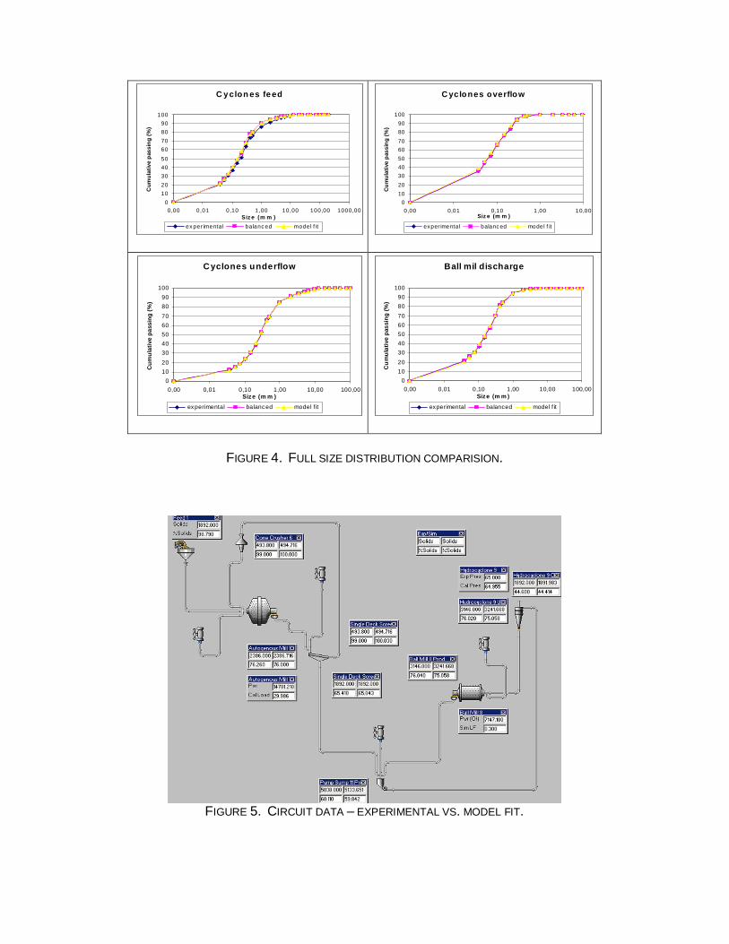
FIGURE 4. FULL SIZE DISTRIBUTION COMPARISION.
FIGURE 5. CIRCUIT DATA – EXPERIMENTAL VS. MODEL FIT.
C y clon es fe ed
01020304050
60708090
100
0,00 0,01 0,10 1,00 10,00 100,00 1000,00Siz e (m m )
Cum
ulat
ive
pass
ing
(%)
ex per imental balanc ed model f it
C yclones overflow
0102030405060708090
100
0,00 0,01 0,10 1,00 10,00Siz e (m m )
Cum
ulat
ive
pass
ing
(%)
exper imental balanc ed model f it
Cyclones underflow
0102030405060708090
100
0,00 0,01 0,10 1,00 10,00 100,00Size (m m )
Cum
ulat
ive
pass
ing
(%)
experimental balanced model f it
Ball mil discharge
0102030405060708090
100
0,00 0,01 0,10 1,00 10,00 100,00Size (m m )
Cum
ulat
ive
pass
ing
(%)
experimental balanced model f it
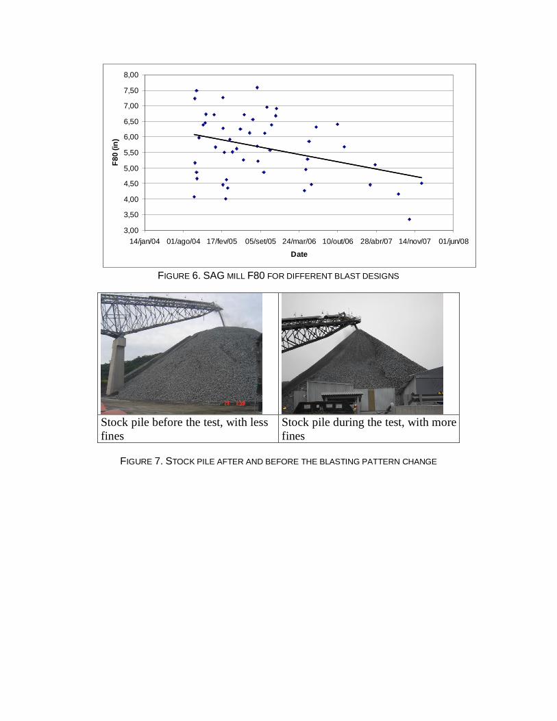
FIGURE 6. SAG MILL F80 FOR DIFFERENT BLAST DESIGNS
Stock pile before the test, with less fines
Stock pile during the test, with more fines
FIGURE 7. STOCK PILE AFTER AND BEFORE THE BLASTING PATTERN CHANGE
3,00
3,50
4,00
4,50
5,00
5,50
6,00
6,50
7,00
7,50
8,00
14/jan/04 01/ago/04 17/fev/05 05/set/05 24/mar/06 10/out/06 28/abr/07 14/nov/07 01/jun/08
Date
F80
(in)