Model 303B Moisture Monitor User Manual - AMETEK ...
70
Model 303B Moisture Monitor User Manual Process Instruments 455 Corporate Boulevard Newark, DE 19702 PN 303230001 , Rev. U
-
Upload
khangminh22 -
Category
Documents
-
view
0 -
download
0
Transcript of Model 303B Moisture Monitor User Manual - AMETEK ...

Model 303B Moisture Monitor
User Manual
Process Instruments 455 Corporate Boulevard
Newark, DE 19702PN 303230001 , Rev. U
ii | 303B Moisture Analyzer Manual
Offices
© 2009 AMETEK
This manual is a guide for the use of the 303B Moisture Monitor Analyzer. Data herein has been verified and validated and is believed adequate for the intended use of this instrument. If the instrument or procedures are used for purposes over and above the capabilities specified herein, confirmation of their validity and suitability should be obtained; otherwise, AMETEK does not guarantee results and assumes no obligation or liability. This publication is not a license to operate under, or a recommendation to infringe upon, any process patents.
SALES AND MANUFACTURING:
USA - Delaware
455 Corporate Blvd., Newark DE 19702 • Tel: 302-456-4400, Fax: 302-456-4444
USA - Oklahoma
2001 N. Indianwood Ave., Broken Arrow OK 74012 • Tel: 918-250-7200, Fax: 918-459-0165
USA - Pennsylvania
150 Freeport Road, Pittsburgh PA 15238 • Tel: 412-828-9040, Fax: 412-826-0399
CANADA - Alberta
2876 Sunridge Way N.E., Calgary, AB T1Y 7H9 • Tel: +1-403-235-8400, Fax: +1-403-248-3550
WORLDWIDE SALES AND SERVICE LOCATIONS:
USA - TexasTel: 713-466-4900, Fax: 713-849-1924
CHINA
Beijing / Tel: 86 10 8526 2111, Fax: 86 10 8526 2141
Chengdu / Tel: 86 28 8675 8111, Fax: 86 28 8675 8141
Shanghai / Tel: 86 21 6426 8111, Fax: 86 21 6426 7818
FRANCE
Tel: 33 1 30 68 89 20, Fax: 33 1 30 68 89 29
GERMANY
Tel: 49 21 59 91 36 0, Fax: 49 21 59 91 3639
MIDDLE EAST - Dubai
Tel: 971 4 881 2052, Fax: 971 4 881 2053
SINGAPORE
Tel: 65 6484 2388, Fax: 65 6481 6588
www.ametekpi.com
Contents | iii
Table of ContentsOffices ..................................................................................................................... iiSafety Notes .........................................................................................................viiWarning Labels ...................................................................................................viiiSPECIAL WARNINGS AND INFORMATION FOR EQUIPMENT USED .... IN HAZARDOUS LOCATIONS ........................................................................ ixWARRANTY AND CLAIMS ................................................................................ x
Chapter 1 OverviewPurpose ................................................................................................................1-1Description ..........................................................................................................1-1Sample System Requirements ..........................................................................1-2
Sample Adjust ..............................................................................................1-2Tubing ............................................................................................................1-3Flow Diagram ...............................................................................................1-4
Optimising Response Time ..............................................................................1-5Non-Interfering ...........................................................................................1-5Interfering .....................................................................................................1-5Contaminating .............................................................................................1-5
Parameters Affecting Operation ......................................................................1-6Flow Calibration ..........................................................................................1-6Density ..........................................................................................................1-6
Pressure ..........................................................................................................1-7 Cell ..................................................................................................................1-8 Alarm Relay ...................................................................................................1-8Special Functions ................................................................................................1-9 Cell Test ..........................................................................................................1-9 Electrical Test .................................................................................................1-9 Stand by Test ...............................................................................................1-10Mathmatical Operation ...................................................................................1-10Zeroing Example ..............................................................................................1-12Flow Example ...................................................................................................1-124 to 20ma Output Range Example ................................................................1-12
Chapter 2 Specifications
Chapter 3 InstallationPrior to Installation ............................................................................................3-1
Analyzer Site Preparation ..........................................................................3-1Installation Connections .............................................................................3-1Power .............................................................................................................3-2AC Mains Operation ...................................................................................3-2External DC Operation ...............................................................................3-4Internal DC Operation ...............................................................................3-4

iv | 303B Moisture Analyzer Manual
Start Up ................................................................................................................3-5Alarm Setpoint Input .........................................................................................3-5Sample System Start-Up ...................................................................................3-6Pressure Vacuum Pump ....................................................................................3-7Rear Panel ............................................................................................................3-7Interconnection Diagram ..................................................................................3-8Grounding Methods ..........................................................................................3-9System Installation Bubble-O Meter .............................................................3-10Bubble O-Meter Diagram ...............................................................................3-11
Chapter 4 User InterfaceOperation ............................................................................................................4-1
Controls and Indicators Table ....................................................................4-1Ooperation and Procedure (Checklist) ...........................................................4-2Transportation ....................................................................................................4-2Flow Doublling Technique ................................................................................4-2
Chapter 5 MaintenanceGeneral .................................................................................................................5-1
Moisture Monitor Interior View ................................................................5-2Parts Replacement .......................................................................................5-3Flow Controller ............................................................................................5-3Power Supply PC Board .............................................................................5-3Main AC Fuse ...............................................................................................5-4Battery ...........................................................................................................5-4CPU Display Board .....................................................................................5-4
Testing ..................................................................................................................5-5Leak Test ........................................................................................................5-5Gas Flow Operational Test .........................................................................5-5Power Supply Voltage Test .........................................................................5-6
Trouble-Shooting ................................................................................................5-6Display and LED Test ..................................................................................5-7Flashing LED Positions ...............................................................................5-7Parameter Settings .......................................................................................5-8Gain ................................................................................................................5-8Factory A/D Gain .........................................................................................5-9Trouble-Shooting Chart ............................................................................5-10Power Supply Board .................................................................................5-12
Chpater 6 Service and PartsParts Ordering Information .......................................................................6-1Parts Lists ......................................................................................................6-2Accessories ....................................................................................................6-3
Contents | v
Apprndix A Conversion Chart
Dew Point ..........................................................................................................A-1Notes ...................................................................................................................A-1
Appendix B NomogramConversion to Relative Humidity ................................................................... B-1
Appendix C NomogramDew Point with Pressure .................................................................................. B-1
Appendix D Glossary of System Conditions
Appendix E Flow Meter Settings
vi | 303B Moisture Analyzer Manual
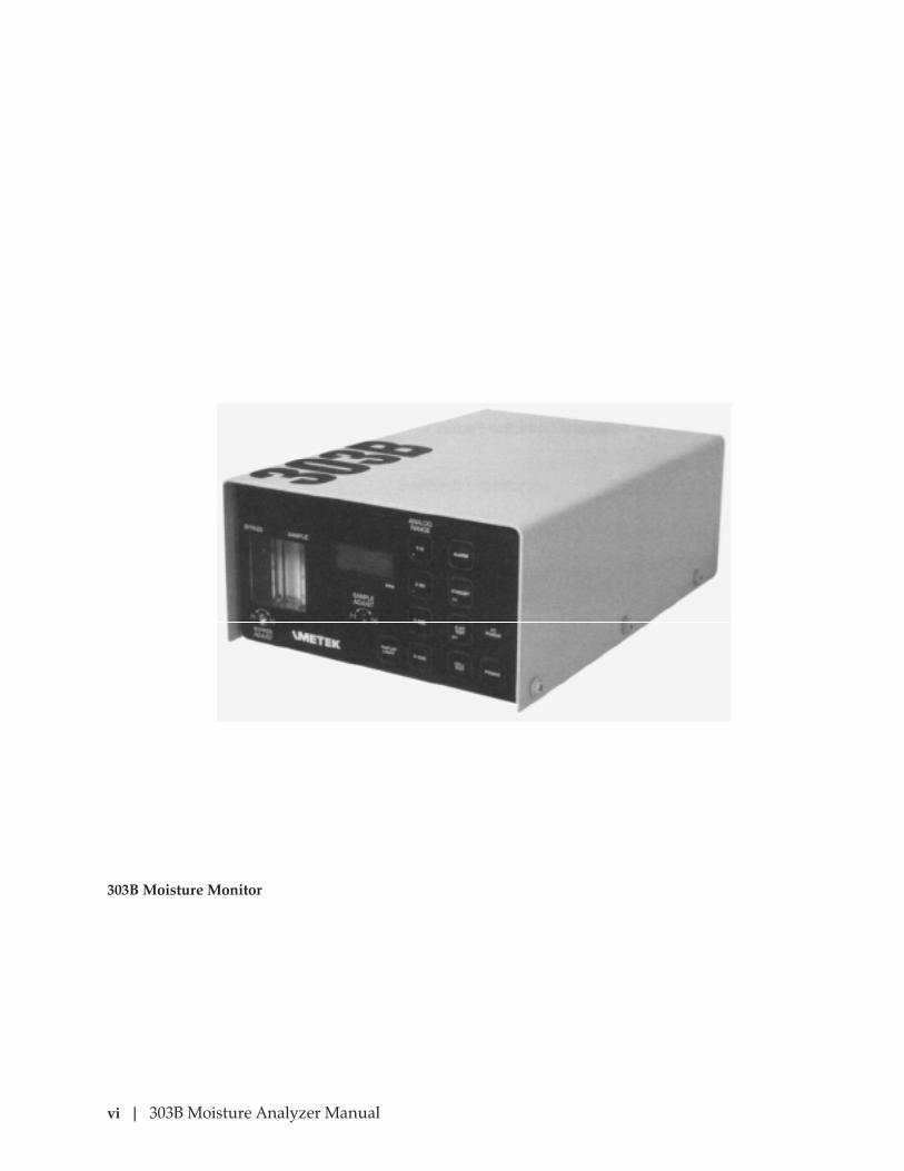
303B Moisture Monitor

Contents | vii
Safety Notes
WARNINGS, CAUTIONS, and NOTES contained in this manual emphasize critical instructions as follows:
WARNING: This equipment has been tested, and declared compliant with international standards for general safety in normal environments, as well as for use in NEC / CEC Class I, Division 2 areas containing flammable gasses in groups A, B, C, and D. Any use of this equipment in a manner not specified by the manufacturer may impair the original protection provided against personal injury or damage to the unit.
Health Hazards Precaution Data: if and when hazardous chemicals or adverse health factors affect the environment or use of the equipment, appropriate precautions are provided.
Service operations given or implied in this manual should be performed only by AMETEK or other qualified personnel.
If the unit is used to measure moisture in toxic or flammable gases, the GAS OUT must exhaust to an area deemed safe and appropriate by the local authority having jurisdiction. Take appropri-ate precautions.
Take care when handling acetone, phosphoric acid and nitric acid in the various procedures.
Check the sample line for leaks before and after connecting.
If sampling a hazardous gas, shut off gas flow and purge the monitor before pressing the POWER switch (LED OFF) or removing the cell.
!WARNING
!WARNING
!WARNING
!WARNING
!WARNING

viii | 303B Moisture Analyzer Manual
PROTECTIVE CONDUCTOR TERMINAL(BORNIER DE L’ECRAN DE PROTECTION)Schutzerde
CAUTION - Risk of electric shock(ATTENTION-RISQUE DE DÉCHARGE ÉLECTRIQUE)Achtung - Hochspannung Lebensgefahr
CAUTION - Refer to accompanying documents(ATTENTION-SE RÉFERER AUX DOCUMENTS JOINTS)Achtung (Beachten Sie beiliegende Dokumente)
CAUTION - Hot Surface(ATTENTION-SURFACE CHAUDE)Achtung - Heiße Oberfläche
Warning Labels
These symbols may appear on the instrument in order to alert you of existing conditions.
Environmental Information (WEEE)
This AMETEK product contains materials that can be reclaimed and recycled. In some cases the product may contain materials known to be hazardous to the environment or human health. In order to prevent the release of harmful substances into the environment and to conserve our natural resources, AMETEK recommends that you arrange to recycle this product when it reaches its “end of life.”
Waste Electrical and Electronic Equipment (WEEE) should never be disposed of in a municipal waste system (residential trash). The Wheelie Bin marking on this product is a reminder to dis-pose of the product properly after it has completed its useful life and been removed from service. Metals, plastics and other components are recyclable and you can do your part by one of the fol-lowing these steps:
• When the equipment is ready to be disposed of, take it to your local or regional waste collection administration for recycling.
• In some cases, your “end-of-life” product may be traded in for credit towards the purchase of new AMETEK instruments. Contact your dealer to see if this program is available in your area.
• If you need further assistance in recycling your AMETEK product, contact our office listed in the front of the instruction manual.
Contents | ix
SPECIAL WARNINGS AND INFORMATION FOR EQUIPMENT USED IN HAZARDOUS LOCATIONS
This Equipment is Suitable for Use in Class I, Division 2, Groups ABCD or Non-Hazardous Areas Only.
Warning - Explosion Hazard - Substitution of Components May Impair Suitability for Class I, Division 2.
AVERTISSEMENT - RISQUE D’EXPLOSION - LA SUBSTITUTION DE COMPOSANTS PEUT RENDRE CE MATERIEL INACCEPTABLE POUR LES EMPLACEMENTS DE CLASSE I, DIVISION 2
Warning - Explosion Hazard - Do Not Disconnect Equipment Unless Power Has Been Switched Off or the Area is Known to be Non-Hazardous
AVERTISSEMENT - RISQUE D’EXPLOSION - AVANT DE DECONNECTER L’EQUIPEMENT, COUPER LE COURANT OU S’ASSURER QUE L’EMPLACMENT EST DESIGNE NON DANGEREUX.
Warning - If This Equipment is to Be Operated in a Class I Div 2 area, the Use of the External 12 Vdc Power Input Option is Strictly Prohibited.
AVERTISSEMENT - SI CET EQUIPEMENT EST UTILISE EN ZONE CLASSE I, DIVISION 2, L’UTILISATION DE L’OPTION “EXTERNE 12 VDC” EST ABSOLUMENT INTERDITE.
When the Controller Unit is to be Operated in a Hazardous Location, the “Alarm Relay Output” Feature is Acceptable for Switching External Circuits Having a Class I, Div 2, Groups ABCD Non-Incendive Output.
The Power Cord Supplied with the Analyzer is Suitable for Flexible Haz-ardous Location Connec-tion. The Mains Plug must be of the Locking and Grounding type.
!Avertisse-
ment
!WARNING
!WARNING
!Avertisse-
ment
!WARNING
!Avertisse-
ment
x | 303B Moisture Analyzer Manual
WARRANTY AND CLAIMS
We warrant that any equipment of our own manufacture or manufactured for us pursuant to our specifica-tions which shall not be, at the time of shipment thereof by or for us, free from defects in material or work-manship under normal use and service, will be repaired or replaced (at our option) by us free of charge, provided that written notice of such defect is received by us within twelve (12) months from date of shipment of portable analyzers or within eighteen (18) months from date of shipment or twelve (12) months from date of installation of permanent equipment, whichever period is shorter. All equipment requiring repair or replacement under the warranty shall be returned to us at our factory, or at such other location as we may designate after obtaining a Returned Material Authorization (RMA) number, transportation prepaid. Such returned equipment shall be examined by us and if it is found to be defective as a result of defective materi-als or workmanship, it shall be repaired or replaced as aforesaid. Our obligation does not include the cost of furnishing any labor in connection with the installation of such repaired or replaced equipment or parts thereof, nor does it include the responsibility or cost of transportation. In addition, instead of repairing or replacing the equipment returned to us as aforesaid, we may, at our option, take back the defective equip-ment, and refund in full settlement the purchase price thereof paid by Buyer.
Process photometric analyzers, process moisture analyzers, and sampling systems are warranted to perform the intended measurement, only in the event that the customer has supplied, and AMETEK has accepted, valid sample stream composition data, process conditions, and electrical area classification prior to order acknowledgment. The photometric light sources are warranted for ninety (90) days from date of shipment. Resale items warranty is limited to the transferable portion of the original equipment manufacturer’s warranty to AMETEK. If you are returning equipment from outside the United State, a statement should appear on the documentation accompanying the equipment being returned declaring that the goods being returned for repair are American goods, the name of the firm who purchased the goods, and the shipment date.
The warranty shall not apply to any equipment (or part thereof) which has been tampered with or altered after leaving our control or which has been replaced by anyone except us, or which has been subject to misuse, neglect, abuse or improper use. Misuse or abuse of the equipment, or any part thereof, shall be con-strued to include, but shall not be limited to, damage by negligence, accident, fire or force of the elements. Improper use or misapplications shall be construed to include improper or inadequate protection against shock, vibration, high or low temperature, overpressure, excess voltage and the like, or operating the equip-ment with or in a corrosive, explosive or combustible medium, unless the equipment is specifically designed for such service, or exposure to any other service or environment of greater severity than that for which the equipment was designed.
The warranty does not apply to used or secondhand equipment nor extend to anyone other than the original purchaser from us.
THIS WARRANTY IS GIVEN AND ACCEPTED IN LIEU OF ALL OTHER WARRANTIES, WHETHER EXPRESS OR IMPLIED, INCLUDING WITHOUT LIMITATION AND WARRANTIES OF FITNESS OR OF MERCHANTABILITY OTHER THAN AS EXPRESSLY SET FORTH HEREIN, AND OF ALL OTHER OBLIGATIONS OR LIABILITIES ON OUR PART. IN NO EVENT SHALL WE BE LIABLE UNDER THIS WARRANTY OR ANY OTHER PROVISION OF THIS AGREEMENT FOR ANY ANTICIPATED OR LOST PROFITS, INCIDENTAL DAMAGES, CONSEQUENTIAL DAMAGES, TIME CHANGES OR ANY OTHER LOSSES INCURRED BY THE ORIGINAL PURCHASER OR ANY THIRD PARTY IN CONNECTION WITH THE PURCHASE, INSTALLATION, REPAIR OR OPERATION OF EQUIPMENT, OR ANY PART THEREOF COVERED BY THIS WARRANTY OR OTHERWISE. WE MAKE NO WARRANTY, EXPRESS OR IMPLIED, INCLUDING WITHOUT LIMITATION ANY WARRANTIES OF FITNESS OR OF MERCHANTABILITY, AS TO ANY OTHER MANUFACTURER’S EQUIPMENT, WHETHER SOLD SEPARATELY OR IN CONJUNC-TION WITH EQUIPMENT OF OUR MANUFACTURE. WE DO NOT AUTHORIZE ANY REPRESENTATIVE OR OTHER PERSON TO ASSUME FOR US ANY LIABILITY IN CONNECTION WITH EQUIPMENT, OR ANY PART THEREOF, COVERED BY THIS WARRANTY.
Overview | 1-1
OVERVIEW
This manual describes operation; provides application, installation, and maintenance data; and lists user replaceable parts for the AMETEK Model 303B Moisture Monitor. Gas correction factor tables are given in Appendi-ces A through C. A glossary of terms is given in Appendix D.
Purpose
The Model 303B measures the water vapor content of most gases, or a mixture of gases, in ppmv or lb/MMscf in Division 2 areas.
Description
The 303B (figure 1-1) is a small, compact, portable, weather proof (NEMA 3R) instrument that operates from an external AC or DC source, or an in-ternal battery. An internal flow meter is provided for use as a flow indica-tor..
• The front panel contains ten membrane key switches, ten windows to view LED’s that show the status of the various functions, two trans-parent windows to view the flow meters and the output display, and two access holes for flow adjustment
• The electrolytic cell, the battery, and two pc boards (cpu/display and power supply) are mounted inside.
• The rear panel contains sample connector fittings, and watertight CGB connectors for the AC or DC power cord and the analog/output alarm wires.
Battery operating life is directly related to the moisture level being meas-ured. At maximum moisture levels, power can be sustained for 24 hours; at low moisture levels, operation can be sustained for over 1 week.
While running, if for any reason external power is lost, the analyzer au-tomatically switches to battery operation. On external power, the bat-tery automatically recharges to full capacity, time permitting, in about 24 hours.

1-2 | 303B Moisture Analyzer Manual
Sample Stream Requirements
Sampling technique is extremely important. Failure to observe needed precautions can result in poor response, incorrect readings, or both.
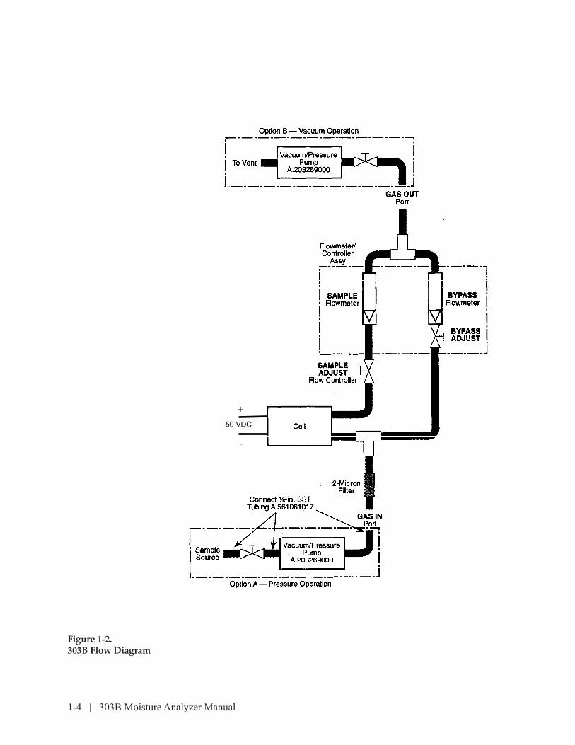
Sample gas pressure must be at least 70 kPa (10 psi) gauge or a booster pump must be used (either pressure on the inlet, or vacuum on the out-let). See Figure 1-2.
Foreign particles are removed from the gas by the 2-micron filter. The SAMPLE ADJUST flow controller must be set to 100 mL/min at 1 atmos-phere. The built-in bypass system permits a portion of the sample gas to bypass the cell while 100 mL/min flows through it.
Bypassing increases sample flow, thereby reducing the time needed for sample to transit the line. Since sample flow is constant, the displayed reading corresponds exactly and linearly to ppm of water vapor in the sample.
The two most common installation errors are in selecting improper sizes and materials for sample lines and fittings between the sample source and the instrument. To assure good results:
• Select a take-off point representative of the sample.
• To minimize dry-down time and response, keep sample line as short as possible.
• Use no material in the inlet system which can absorb and desorb any amount of moisture or allow moisture permeation.
• Eliminate water absorbing materials.
• Insulate the system to eliminate large temperature swings.
• Maintain good pressure control.
• Keep the cell as dry as possible between uses.
• Remove contaminating substances from sample if possible.
• Filter out all particulate matter larger than 10 µm; if not, the internal filter will foul quickly.
• Be sure sample temperature does not exceed 40°C.
• Be sure the sample is free of oil mist.

Overview | 1-3
Sample gas tubing (PN A.571061017) is recommended. It should be chemi-cally cleaned and passivated, thermocouple grade 316 stainless steel. Cop-per, brass, and polycarbonate are not to be used. Most plastics or elasto-mer materials are unsatisfactory because of their relatively high moisture permeability.
All tubing should be minimum length; [3 m (10 ft)] and ID; 3.2 mm [0.128 in. (1/8 in.)] OD is recommended. Use Teflon® Fluorocarbon tape or American Sealants Co. Locktite® 545 on threaded connections. Do not use pipe, rubber, or similar cements. The sample system should be leak-checked periodically.
*Reg. U.S. Pat. & T.M. Off.
1-4 | 303B Moisture Analyzer Manual
Figure 1-2.303B Flow Diagram
+
-
50 VDC

Overview | 1-5
Optimizing Response Time
The built-in bypass system is always used to optimize response time. Un-less the sample gas is hazardous or costly, bypass flow should be as high as possible. The bypass system also is valuable with the instrument in portable service analyzing discrete samples. In these applications, bypass helps to purge gas cylinder valves, pressure regulators and tubing prior to sampling.
Non-interfering, Interfering, and Contaminating Gases
Non-interfering
The cell is not affected by gases such as nitrogen, methane, and many aliphatic and aromatic hydrocarbons. The instrument is ideally suited for analysis of these gases.
Interfering
When analyzing moisture vapor in hydrogen, oxygen, or gas mixtures containing a high percentage of either gas, the display will read artificially high. On air for example, it may read up to 10 percent high. This is caused by the electrolysis of moisture formed by recombination of free hydrogen or oxygen. A recommended flow doubling technique to correct for hydro-gen and oxygen is described in Chapter 4.
Contaminating
These substances damage the instrument or cell. Instrument readings may or may not be immediately affected.
Certain corrosive acid gases will corrode the tubing and flow control sys-tem, but will not harm the cell. The reading will not be affected until the damage is sufficient to cause line leaks, poor flow control, etc. Typical ex-amples are chlorine and sulfur dioxide.
Certain unsaturated hydrocarbons gradually coat the cell with a polymer-ic coating. The reading is affected gradually as the cell becomes inactive. A typical example is butadiene.
Entrained liquids and solids also can affect cell performance. Filtering usually prevents this problem.
Do not allow liquids to pass through the cell.
1-6 | 303B Moisture Analyzer Manual
Interfering and Contaminating
Some substances will immediately contaminate the cell and cause incor-rect readings. Typical examples are graphite dust, hydrogen fluoride, and ammonia.
Parameters Affecting Operation
Flow Calibration
The 303B is an easy to operate, but flow dependent instrument. To ob-tain an accurate moisture measurement the operator must set the sample flow to the equivalent of 100 mL/min at 1 atmospheric pressure and 25°C (77°F). If sample flow is off by ten percent, the measurement will general-ly also be off by ten percent. If the user is to achieve the specified accura-cy, the simple flow setting procedure described in Chapter 3-5, Sample System Hook Up, steps 4, 5 and 6, must be performed.
The 303B comes equipped with sample and bypass flow meters. These flow meters are not high precision devices and are to be used exclusively as flow indicators. We suggest the operator use a relatively high precision flow meter, such as a bubble-o-meter (soap bubble flow meter) to set the sample flow through the monitor. Of course, the external flow meter must be calibrated for the sample gas and the bubble-o-meter must be correct-ed for temperature and pressure.
Operating at a flow other than 100 mL/min at 25°C (77°F) and 1 atmos-phere requires a display reading correction to obtain the proper ppm. In general, doubling the flow doubles the indicated moisture reading.
No cell calibration is needed because the measurement is quantitative and its response to moisture is linear from less than 1 to 1000 ppm, or 50 lb/MMscf.
Density
Sample flow must be readjusted if gases of different densities are ana-lyzed.
A flow meter will not be at the same point for a flow of 100 mL/min for two gases of different densities
Flow meters are calibrated for a specific gas at a specific temperature and
NOTE

Overview | 1-7
pressure. Volumetric flow measuring devices such as the bubble-o-meter are not affected by different gas densities and will provide the correct flow independent of density (at constant temperature and pressure).
Pressure
Since the flow controller maintains a constant flow, sample input pressure changes do not affect instrument response. Pressure should be regulated between 70 and 700 kPa (10 and 100 psi) gauge, but the instrument can ac-commodate higher sample gas pressures if an external regulator is used to reduce the pressure to the 70 to 700-kPa range. Use an external pump for sample pressures below 70 kPa gauge.
Gas usually exits the system at atmospheric pressure. If the instrument is operated with a back pressure, an appropriate correction must be made to assure that flow through the instrument corresponds to 100 mL/min at 1 atmosphere and 25°C.
Temperature
A change in sample temperature does not affect the way the instrument measures moisture. It does, however, affect gas density and moisture ab-sorbed in sample system parts.
The unit is calibrated to operate at 25°C. If operated at a different tem-perature, density change and the consequent change in moisture is based on °K (= °C + 273).
Actual_Moisture • [(273 + 25) Displayed_Moisture_Reading = --------------------------------------------- (Act_temperature C + 273)]
The density change effect is about 0.33 percent/°C, but if the cell is cali-brated with the bubble-o-meter with temperature compensation, all tem-perature/density effects are again 0.
Other effects, a higher temperature may have is to release moisture held in system components, even that trapped in stainless steel tubing. The higher the tubing free carbon content, the higher is the moisture level it can trap. Also, oils, grease, and other hydroscopic compounds coating component walls can sorb and desorb moisture. As temperature rises,
1-8 | 303B Moisture Analyzer Manual
these components can release their moisture, which will be measured as if they were in the sample stream. The reverse also is true; as sample tem-perature falls, moisture will be absorbed into the components, lowering the moisture readings. The only fix is to remove all absorbing/desorbing parts from the system.
Cell
The cell converts the water-content of the sample gas passing through it to an electrical current. The cell determines the moisture by absorbing the gaseous water, and electrolyzing the absorbed water. This accounts for the high degree of accuracy and specificity, since the process is virtually unique for water and consumes at least 99.9 percent of the gaseous water at levels as low as 1.0 ppm or as high as 2000 ppm.
The assembly is cased in epoxy resin for mechanical protection. This nor-mally precludes damage from any cause except objects which may en-ter through the cell ports.
If flow of a sample gas with specific moisture content is constant, the moisture is absorbed and electrolyzed, producing a constant current. When flow is increased, electrolyzing current increases proportionally. Current is directly and linearly related to mass flow, and can be calculated from Faraday’s law.
When these factors are considered for water being electrolyzed by a moisture cell, current in µA/ppm of water is given by IµA = (0.132 x flow) where flow is the sample flow in mL/min, measured at 100 kPa (1.00 atm) pressure and 25°C. For example, at 20 mL/min, 1 ppm of water produces 2.64 µA; 100 mL/min, 13.2 µA. The current is displayed as ppm.
Alarm Relay
The alarm relay has two contacts: normally open (NO) and normally closed (NC). With the relay OFF, NO contacts are open and NC contacts are closed. With the relay ON, NO contacts are closed and NC contacts are open.
There are two relay modes controlled by jumper JP2 (figure 3-2): low-power (pins 2 and 3) and fail-safe (pins 1 and 2). In low-power mode, the relay coil turns ON when the moisture reading is above the alarm set-point; the coil turns OFF with low ppm readings, such that battery power can be conserved.
The relay works against a single setpoint setting. In the fail-safe mode, the relay coil is ON when the moisture reading is below the alarm setpoint
Overview | 1-9
and OFF when the reading goes above the setpoint. Since the coil is nor-mally ON with low readings, if power is lost accidentally, the coil turns OFF which, in turn, reverses the relay contacts as if a high ppm reading oc-curred; hence fail-safe.
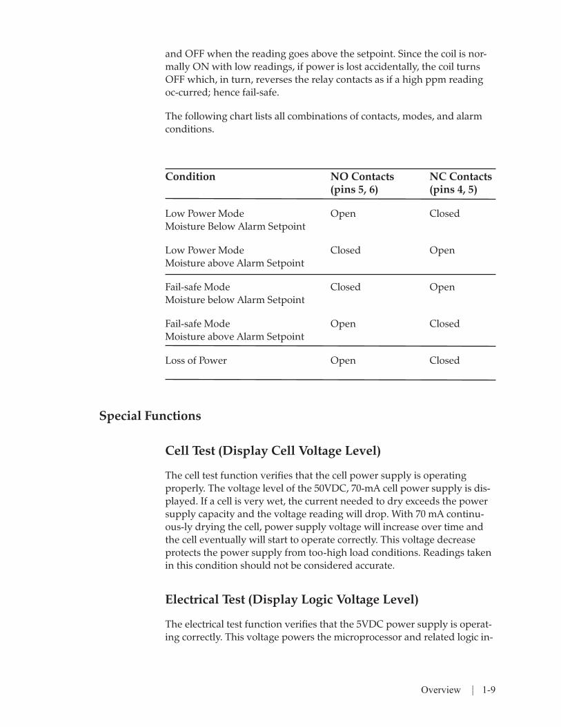
The following chart lists all combinations of contacts, modes, and alarm conditions.
Condition NO Contacts NC Contacts (pins 5, 6) (pins 4, 5)
Low Power Mode Open Closed Moisture Below Alarm Setpoint
Low Power Mode Closed Open Moisture above Alarm Setpoint
Fail-safe Mode Closed Open Moisture below Alarm Setpoint
Fail-safe Mode Open Closed Moisture above Alarm Setpoint
Loss of Power Open Closed
Special Functions
Cell Test (Display Cell Voltage Level)
The cell test function verifies that the cell power supply is operating properly. The voltage level of the 50VDC, 70-mA cell power supply is dis-played. If a cell is very wet, the current needed to dry exceeds the power supply capacity and the voltage reading will drop. With 70 mA continu-ous-ly drying the cell, power supply voltage will increase over time and the cell eventually will start to operate correctly. This voltage decrease protects the power supply from too-high load conditions. Readings taken in this condition should not be considered accurate.
Electrical Test (Display Logic Voltage Level)
The electrical test function verifies that the 5VDC power supply is operat-ing correctly. This voltage powers the microprocessor and related logic in-

1-10 | 303B Moisture Analyzer Manual
tegrated circuits (ICs), and should always be between 4.80 and 5.20 volts.
If this voltage is out-of-range, most likely the 303B will not operate at all and the function cannot be accessed. If this function shows an out-of-range condition, voltage must be measured directly at the power supply board to verify the voltage error, and the power supply board should be replaced. If the power supply voltage level is in-range when measured di-rectly, the power supply ribbon cable or the cpu/display board needs to be replaced.
Stand-By Test (Keep Cell Dry While Transporting)
The stand-by function is used while transporting a 303B to maintain a dry cell. When this mode is started, all power is shut off, except to the cell and the microprocessor, which are powered from ac line power (if it is plugged-in) or from the battery. If ac line power is lost while in this mode, the 303B automatically switches to the battery. Power use is minimized to maximize battery life so that the cell can be maintained dry as long as possible. To save battery power, the 303B should, whenever possible, be plugged into ac line power.
Using this mode while transporting the 303B, the cell will stay dry, and be able to give accurate moisture readings almost immediately after hooking up at the new location.
Mathematical Operation
Moisture determination is based on a straight line formula. Cell current is converted to a digital number through an analog-to-digital (A/D) con-verter where further conversions can be done by the microprocessor. The over-all formula is:
ppm = (A/D_number • factory_gain • gain) – offset
or lb/mmscf = (A/D_number • factory_gain • gain • 0.0476) – offset
By changing jumper JP4, PPM (pins 2, 3) or LB/MMSCF (pins 1, 2) can be displayed (figure 2-2). The jumper changes the microprocessor formu-las automatically. Since 1 ppm = 0.0476 lb/mmscf, this factor is the only differ-ence between the two formulas.
The factory_gain number converts the A/D_number to ppm values and is determined by applying multiples of 1.32 µA/ppm and calculating the cor-

Overview | 1-11
rect factory_gain number for a particular display/cpu board. Through this, each instrument meets the published specifications. Since this calibration is so complex, it is not recommended that this number ever be changed. In case the number is accidentally overwritten or changed, a label at-tached to the display/cpu board has the factory_gain number inscribed. If a dif-ferent multiplier is desired in the formulas, then use the gain number.
Gain and offset factors compensate for many different effects. Since their defaults are 1 and 0, they have no affect on the moisture readings.
Gain is a multiplier of the moisture reading, such that if the reading is 88.4 ppm and gain is changed from 1.0 to 0.5, the reading would change to 44.2 ppm.
Offset is a subtractor to the moisture reading, such that if the reading off-set is changed from 0.0 to 5.0, the moisture reading would change to 5.54 lb/mmscf.
The formulas above can be simplified to the following if you plan on us-ing only the gain and offset.
Displayed_moisture_value = (Actual_moisture_value • gain) – offset
If you need to calculate the actual moisture value after changing gain and offset, the formula is:
(Displayed_moisture_value + offset) Actual_moisture_value = --------------------------------------------------- gain
Gain and offset values have limitations. Both have only one decimal place, which can be limiting if fine adjustments are needed when changing gain. Also, both values have a limited range of 0.0 to 655.3. Negative numbers are not allowed, which can limit some offset changes. The most important thing to remember is that the offset number is always subtracted, which makes it impossible to add moisture to the reading.
By changing offset it is possible to have a negative displayed moisture value; a negative value will flash. When offset is 0, it is impossible to have a negative moisture value.
Listed on the following pages are some examples of what these factors can do, both to lb/mmscf and ppm readings.

1-12 | 303B Moisture Analyzer Manual
Zeroing Example
By supplying a zero-moisture calibration gas, the analyzer may not dry down to 0. If the analyzer stops drying down at 3.2 ppm, an offset of 3.2 can be entered to have the display read 0.0. This is probably the most common use for the offset factor.
If the analyzer later dried down below 3.2 ppm, the display would flash indicating that the value is negative. For example, to get a 0.0 reading if 0.3 were flashing, offset must be changed from 3.2 to 2.9.
Refer to page 5-8 of this manual to change offset parameter.
Flow Compensation Example
The analyzer requires a 100-mL flow to operate properly, but if the pro-cess can supply only a 50-mL flow, gain can compensate. For example, the reading is 112.0 ppm at a 100-mL flow; when flow is reduced to 50 mL, 56.0 is displayed. To show the correct moisture, gain can be in-creased from 1.0 to 2.0, causing the display to increase back to 112.0 ppm.
The same can be applied in reverse. For a 4.75 lb/mmscf reading at 100mL/min, and increasing the flow to 200 mL flow, 9.50 is displayed. To display the correct moisture, gain can be decreased from 1.0 to 0.5, caus-ing the reading decrease back to 4.74 lb/mmscf.
Change the 4 to 20-mA Output Range Example
These examples change the 4 to 20-mA output, but the display will not show the correct ppm readings.
For example, if you want to have readings from 50 to 100 ppm be mapped into the 4 to 20-mA output at 0 to 100 percent, gain must first be changed from 1.0 to 2.0. This changes the ppm readings from 50 to 100 to 100 to 200. Then, by changing offset from 0.0 to 100.0, the readings change again from 100 to 200 to 0 to 100. Then, simply set the 4 to 20-mA range to 0 to 100; the 50 to 100 ppm readings then will be 0 to 100 percent of the 4 to 20-mA output. As stated earlier, 0 to 100 ppm will be displayed even though the real moisture levels are 50 to 100 ppm.
Overview | 1-13
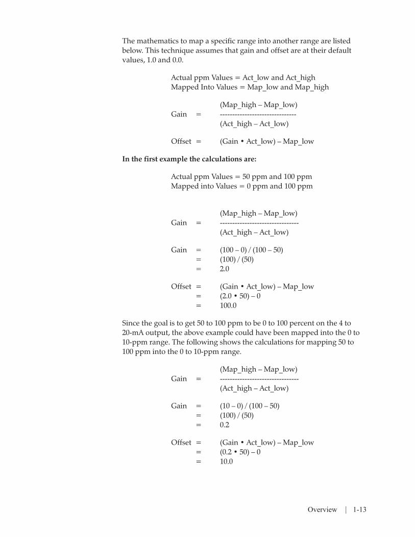
The mathematics to map a specific range into another range are listed below. This technique assumes that gain and offset are at their default values, 1.0 and 0.0.
Actual ppm Values = Act_low and Act_high Mapped Into Values = Map_low and Map_high
(Map_high – Map_low) Gain = ------------------------------- (Act_high – Act_low)
Offset = (Gain • Act_low) – Map_low
In the first example the calculations are:
Actual ppm Values = 50 ppm and 100 ppm Mapped into Values = 0 ppm and 100 ppm
(Map_high – Map_low) Gain = -------------------------------- (Act_high – Act_low)
Gain = (100 – 0) / (100 – 50) = (100) / (50) = 2.0
Offset = (Gain • Act_low) – Map_low = (2.0 • 50) – 0 = 100.0
Since the goal is to get 50 to 100 ppm to be 0 to 100 percent on the 4 to 20-mA output, the above example could have been mapped into the 0 to 10-ppm range. The following shows the calculations for mapping 50 to 100 ppm into the 0 to 10-ppm range.
(Map_high – Map_low) Gain = -------------------------------- (Act_high – Act_low)
Gain = (10 – 0) / (100 – 50) = (100) / (50) = 0.2
Offset = (Gain • Act_low) – Map_low = (0.2 • 50) – 0 = 10.0

1-14 | 303B Moisture Analyzer Manual
This page intentionally left blank.
Specifications | 2-1
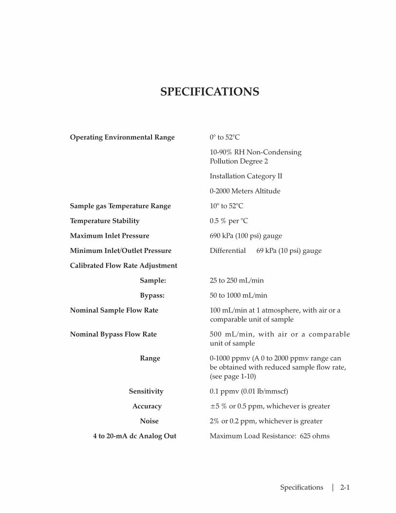
SPECIFICATIONS
Operating Environmental Range 0° to 52°C
10-90% RH Non-Condensing Pollution Degree 2
Installation Category II
0-2000 Meters Altitude
Sample gas Temperature Range 10° to 52°C
Temperature Stability 0.5 % per °C
Maximum Inlet Pressure 690 kPa (100 psi) gauge
Minimum Inlet/Outlet Pressure Differential 69 kPa (10 psi) gauge
Calibrated Flow Rate Adjustment
Sample: 25 to 250 mL/min
Bypass: 50 to 1000 mL/min
Nominal Sample Flow Rate 100 mL/min at 1 atmosphere, with air or a comparable unit of sample
Nominal Bypass Flow Rate 500 mL/min, with air or a comparable unit of sample
Range 0-1000 ppmv (A 0 to 2000 ppmv range can be obtained with reduced sample flow rate, (see page 1-10)
Sensitivity 0.1 ppmv (0.01 lb/mmscf)
Accuracy ±5 % or 0.5 ppm, whichever is greater
Noise 2% or 0.2 ppm, whichever is greater
4 to 20-mA dc Analog Out Maximum Load Resistance: 625 ohms

2-2 | 303B Moisture Analyzer Manual
Alarm Relay N o r m a l l y o p e n a n d n o r m a l l y c l o s e d contac t s ; ra ted for res i s t ive loads on ly : 1 A, 24 Vac/dc
Alarm Setpoint 0 to 2000 ppm
• From 0.0 to 999.9, 0.1 resolution
• From 1000 to 6553, 1.0 resolution
Power Supply
AC 100-130 Vac, 47-63 Hz, 20W
200-260 Vac, 47-63 Hz, 20W
Factory Configured
DC 12 - 14 Vdc, external and internal,
20W Max ext.
Enclosure Classification NEMA 3R
Dimensions 34.3 cm (13.5 in) deep
23.5 cm (9.25 in) wide
12.7 cm (5 in) high
Weight (fully optioned) 6.4 kg (14 lb)
Factory Defaults
Factory Gain: Specified on board label
Gain: 1.00
Offset: 0.0
Alarm Setpoint: 2000 ppm or 100 lb/mmscf
Analog Output Range: 0 to 2000 ppm or 0 to 100 lb/mmscf

Specifications | 2-3
Approvals and Certifications
UL/CSA General Safety Requirements Class 1, Division 2, Groups ABCD T4A
Electromagnetic Compatibility Directive; EN61326-1 Industrial
Low Voltage Directive; EN61010-1
Pressure Equipment Directive Complies with all relevant European direc tives

2-4 | 303B Moisture Analyzer Manual
This page intentionally left blank.
Installation | 3-1
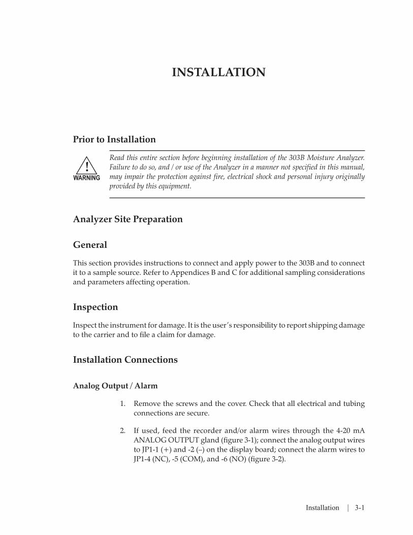
INSTALLATION
Prior to Installation
Read this entire section before beginning installation of the 303B Moisture Analyzer. Failure to do so, and / or use of the Analyzer in a manner not specified in this manual, may impair the protection against fire, electrical shock and personal injury originally provided by this equipment.
Analyzer Site Preparation
General
This section provides instructions to connect and apply power to the 303B and to connect it to a sample source. Refer to Appendices B and C for additional sampling considerations and parameters affecting operation.
Inspection
Inspect the instrument for damage. It is the user’s responsibility to report shipping damage to the carrier and to file a claim for damage.
Installation Connections
Analog Output / Alarm
1. Remove the screws and the cover. Check that all electrical and tubing connections are secure.
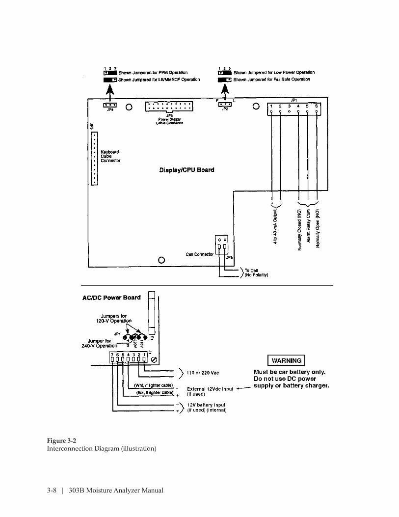
2. If used, feed the recorder and/or alarm wires through the 4-20 mA ANALOG OUTPUT gland (figure 3-1); connect the analog output wires to JP1-1 (+) and -2 (–) on the display board; connect the alarm wires to JP1-4 (NC), -5 (COM), and -6 (NO) (figure 3-2).
!WARNING

3-2 | 303B Moisture Analyzer Manual
Power
The AMETEK 303B moisture monitor is equipped with three power source options. The unit may be powered from either of two external power sources or an internal battery. Informa-tion on the characteristics and limi-tations regarding these sources are described below:
AC Mains Operation
1. The 303B is shipped with the internal AC/DC power supply board jumpered and fused for the mains line voltage ordered by the customer (i.e. 120 vs. 240 VAC).
This configuration must not be altered by the operator! Only qualified service person-nel may access the interior of the unit to change this setting and fuse. The rear panel label must be clearly remarked to indicate the new AC source information. If qualified personnel are not available to perform these tasks, contact AMETEK Service.
The 303B is shipped with three feet (.91m) of nondetachable, extra-hard usage (Class 1, Div 2 requirement), AC power cord, pre-terminated at the unit. For European and other overseas products, this cable will be of the CENELEC Harmonized type. In addition, the wire size will be .82 mm2, or equivalent, for 10 amp use, and have the international insulation color code of brown, light blue and green/yellow stripe.
In the case of use in North America the cable will be U.L. 62 and/or CSA C22.2 No. 49, 18 AWG, and have the North American color code of black, white, and green. In addition, if a molded cord set is supplied, it will be properly approved for North American use or Harmonized for European application.
If the above supplied power cable is not sufficient due to length, or unique specification, the user may replace the cordage (for use in non-hazardous areas), but must abide by the following safety requirements:
• Adhere to nationally recognized standards for cordage for use with this type of equipment, having the power requirements stated in this manual and for use in the intended environment.
• Retain the original connection characteristics in the new connection and have the connection performed by qualified service personnel. This in-cludes:
!WARNING

Installation | 3-3
• Protective ground connection, see Fig. 3-3.
• Proper connection to AC disconnect connector at the internal power supply.
• New cordage diameter must be compatible with the strain relief provided.
• Strain relief must be tightened securely as to not allow slippage when cordage is pulled or pushed from the outside.
• Allow six inches of loose power wire inside the unit.
If the unit is to be hard wired into the installation’s power system it must be done so in a safe area only and treated as permanently connected equipment and installed according to the local, nationally recognized procedures for equipment of this type and stated power requirements. The installation must have the following characteristics in addition to the above:
• Have a separate disconnect device such as a switch or circuit breaker included as part of the building installation. The power rating for the disconnect should be sized to accommodate the requirements stated on the rear of the unit.
• This device must be in close proximity to the equipment as to be in easy reach of the operator.
• This device must be marked as the disconnecting device for this equip-ment.
If a mains plug is to be attached to the end of the original cordage, it must comply with the relevant, nationally recognized specifications and/or standards for detachable mains plugs for the stated power requirements of this equipment. If the unit is to be operated in a hazardous location, the plug must be of the grounded and locking type.
Hazardous location operation: For use in Class I, Div 2 locations, AC power connection must be made using three feet maximum of agency approved extra-hard usage power cable, terminated with a plug of the grounded and locking type. See NEC section 501-3b6 or CEC 18-172,174
When the 303B is connected to the AC power mains, the internal battery will either be in a state of recharge, or full charge, maintained by the internal battery charger portion of the power supply. Note that the front panel AC LED is illuminated.
NOTE

3-4 | 303B Moisture Analyzer Manual
External DC Operation (12Vdc, negative ground, vehicular)
This option is available for safe area operation only. Do not attempt to operate this equipment or charge the battery using this option in a hazardous (classified) location!
The 303B is supplied with approximately 12 feet (4m) of low voltage cable, terminated at one end with a standard vehicular male cigarette/accessory plug. The unterminated end is to be inserted through the designated 12 V strain relief on the rear panel and terminated into the AC/DC power board connector at J1 as per Fig. 3.2.
Using the supplied auto lighter plug and cable, connect its black and white leads to J1-5 (+) and J1-4 (-) respectively. Tighten the strain relief securely so that the dc power lead cannot be pulled or pushed through the strain relief from the outside.
The plugged end is intended for insertion into the fused, mating con-nector of a 12 VDC, negative ground vehicle, only. The value of this fuse should be 1A minimum, with a voltage rating of 18Vor greater. This external connection is not intended to be energized by devices such as DC power supplies, battery chargers, generators, and the like.
Non-adherence to the above requirements, or use of the equipment in a manner not speci-fied in this manual, may im-pair the protection against fire, electrical shock and damage, originally provided by this equipment.
When the 303B is properly connected to a vehicle, the internal battery will be in a state of recharge or full charge, maintained by the internal bat-tery charger portion of the power supply. Note that the front panel AC LED does not illuminate during external DC operation.
Internal DC Operation
The 303B provides an internal 12V, sealed lead acid battery for portable use. There are no special connections or preparations needed to use this feature.
Note that the front panel AC LED does not illuminate during inter-nal battery use.
2. Check that jumper plug JP4 on the display board is set for your reading; pins 1 and 2 for ppm, pins 2 and 3 for lb/mmscf.
!WARNING
!WARNING
NOTE
Installation | 3-5
3. Check that jumper plug JP2 is set as desired for your alarm operation; pins 1 and 2 (F) for fail-safe (relay actuated with readings below setpoint, or pins 2 and 3 (L) for low power (relay actuated with readings above set-point).
4. Check that the cell leads are secure in plug JP6.
5. Check that the keyboard cable is secure in plug JP5.
6. Check that the power supply cable is secure in plug JP3.
7 Connect the power plug (if used) to either the ac or dc supply.
Start-Up
1. Press the POWER key (LED ON). The analyzer goes through a self check of EEPROM and LED/display, followed by a display of the software revision number (P X.XX). With POWER ON and no sample flow, electrolysis will gradually dry the cell.
2. Press the CELL TEST key. The CELL TEST and an ANALOG RANGE key LED will flash and the displayed value will read toward 47-53 (volts).
3. Press the CELL TEST key (LED OFF). Wait for the display to stabilize.
Alarm Setpoint Input
1. Press the ALARM key. The ALARM, +, and – LED’s will flash and the last alarm setpoint will be displayed.
2. Press the + or – key to increment or decrement the setpoint to the desired value.
3. When the desired value is displayed, press ALARM to store the value; ProG will be displayed until the value is stored.
If the STANDBY, CELL TEST, ELECT TEST, 0-1000, 0-2000, or DISPLAY LIGHT key is pressed during the routine, the new value is not stored and normal moisture measuring begins.
NOTE

3-6 | 303B Moisture Analyzer Manual
Sample System Hook-Up
1. Do the leak test given in Section 4-6.
If the instrument is used to measure moisture in toxic or flammable gases, the GAS OUT must exhaust to an area deemed safe and appropriate by the local authority having ju-risdiction.
To prevent damage to the moisture cell, it is necessary to purge your sample line prior to connecting the analyzer. Failure to do so may void the warranty.
2. Connect a source of gas at 70 to 700 kPa (10 to 100 psi) gauge with a moisture content of less than 100 ppm to the GAS IN fitting. Nitrogen, instrument air, argon, or helium is commonly used.
3. Close the BYPASS ADJUST valve. Do not over tighten.
4. Connect a precision flow meter such as the bubble-o-meter (figure 3-4) to the GAS OUT fitting. The 303B flow meters must be calibrated for all sample gases (refer to Appendix E for correction factors).
5. Set the SAMPLE ADJUST so that the external flow meter indicates 100 mL/min at 25°C (77°F) and 1 atmosphere.
6. Note the reading on the 303B internal flow meter. You may want to mark the tube with a permanent marker.
7. Select the lowest ANALOG RANGE that does not cause the recorder to read full scale.
8. Continue to operate until the displayed moisture level stabilizes.
9. If operating on dc (internal battery), unplug the ac power at the source. The AC POWER LED should go out and the display reading may fluctu-ate slightly. This slight difference between ac and dc operation is normal and will disappear over a short period of time.
10. If the monitor is operating correctly, shut off sample gas and press the POWER switch (LED off). If it is not operating correctly, review these procedures to ensure they have been properly followed, and read the following manual sections. There are troubleshooting procedures in Section 4.
11. Install the cover and tighten the screws.
!WARNING
!WARNING
Installation | 3-7
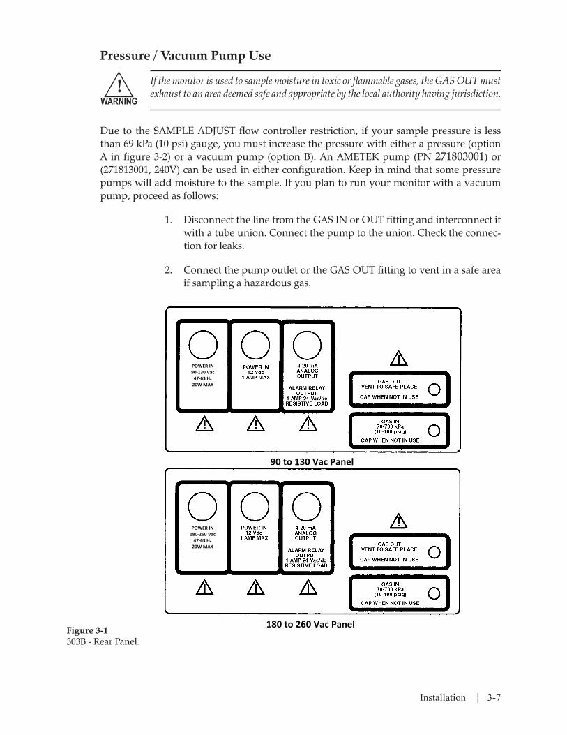
Pressure / Vacuum Pump Use
If the monitor is used to sample moisture in toxic or flammable gases, the GAS OUT must exhaust to an area deemed safe and appropriate by the local authority having jurisdiction.
Due to the SAMPLE ADJUST flow controller restriction, if your sample pressure is less than 69 kPa (10 psi) gauge, you must increase the pressure with either a pressure (option A in figure 3-2) or a vacuum pump (option B). An AMETEK pump (PN 271803001) or (271813001, 240V) can be used in either configuration. Keep in mind that some pressure pumps will add moisture to the sample. If you plan to run your monitor with a vacuum pump, proceed as follows:
1. Disconnect the line from the GAS IN or OUT fitting and interconnect it with a tube union. Connect the pump to the union. Check the connec-tion for leaks.
2. Connect the pump outlet or the GAS OUT fitting to vent in a safe area if sampling a hazardous gas.
!WARNING
90 to 130 Vac Panel
180 to 260 Vac Panel
POWER IN 90‐130 Vac 47‐63 Hz 20W MAX
POWER IN 180‐260 Vac 47‐63 Hz 20W MAX
Figure 3-1303B - Rear Panel.
3-8 | 303B Moisture Analyzer Manual
Figure 3-2Interconnection Diagram (illustration)

Installation | 3-9
Figure 3-3Proper and Improper Grounding Methods

3-10 | 303B Moisture Analyzer Manual
System Installation Bubble-O Meter
1. Wet the entire inside of the bubble-o-meter (tube) with a dilute liquid detergent or shampoo solution through the top of the tube.
2. Tilt the tube sideways and turn it to wet the entire inside surface.
3. Hold the tube upright and check that the liquid level in the rubber bulb is slightly below the Y arm. If level is too high, bubbles will flow without squeezing the bulb. Pour out some of the liquid if this happens.
4. Connect the bottom Y inlet port to a gas source with rubber or plastic tubing.
5. Measure the gas flow rate by carefully squeezing the bulb to form a single bubble and, with a stopwatch, timing its transit time between two adjacent calibration marks.
When making precision measurements, use the gas law equations to correct for ambient temperature and vapor pressure, and water tension above the soap solution; be sure to add distilled water occasionally to compensate for evaporation.
When making measurements at low flow rates with gases like helium or hydrogen, form several films ahead of the one being timed to prevent gas loss by diffusion through the film.
!WARNING
!WARNING

Installation | 3-11
Figure 3-4Bubble-O-Meter PN 303030006.

3-12 | 303B Moisture Analyzer Manual
This page intentionally left blank.

User Interface | 4-1
OPERATION Controls and Indictors
Control Function Normal Measuring
BYPASS flow meter Sets and reads bypass gas flow rate. Mid-scale.
SAMPLE flow meter Reads sample flow rate. 100 cc/min at 1 atm
Moisture display Liquid crystal display (LCD) shows moisture Moisture reading value or other data depending on mode.
SAMPLE ADJUST Screwdriver adjustment for sample flow As needed for SAMPLE rate. flow meter readingBYPASS ADJUST Screwdriver adjustment for reference As needed for BYPASS flow rate. flow meter reading
ANALOG RANGE Keys enable selection of one of four 4 to One of the four LED keys and LED’s 20-mA output ranges. LED indicates which must always be ON range is active + key Plus key increments value selections for Not applicable gain, offset, factory gain, and alarm set-point entries.
– key Minus key decrements value selections Not applicable for gain, offset, factory gain, and alarm setpoint entries. DISPLAY LIGHT key Back lights the display for about 1 minute As needed
ALARM key and LED Enables alarm setpoint adjustment with LED ON if moisture + and – keys. reading is above alarm setpoint.STANDBY key Places the unit in a standby mode by Not applicableand LED reducing power consumption. ELEC TEST key and LED Tests 5V power supply. Not applicable
CELL TEST key and LED Tests cell 50V power supply. Not applicable
AC POWER LED ON when the unit is plugged into ac out-let. ON (if on ac power)
POWER key and LED Turns instrument power ON and OFF. ON
ofst key Enables changing offset parameter when Not applicable key is pressed at power-up (refer to Para- meter Setting in Section 4).gain key Enables changing gain parameter when Not applicable key is pressed at power-up (refer to Pa- rameter Setting in Section 4). Operating Procedure (Checklist)
USER INTERFACE
4-2 | 303B Moisture Analyzer Manual
Operating Procedure (Checklist)
With the instrument connected to a sample gas stream, proceed as follows:
1. Press the POWER key (LED ON). The system will run through a series of test displays, then start displaying moisture values.
2. Check sample gas for:
• Pressure — Regulated 69 to 690 kPa ± 5 percent (10 to 100 psi) gauge ±5 percent
• Flow—≈100mL/minat1atmosphere
• Bypass—≈mid-scale
• GAS IN temperature — between 10°C and 50°C
Refer to the Parameters Affecting Operation — Temperature in Section 1 for temperature variation factor.
To prevent cell saturation, always shut sample gas off before turning the monitor off.
3. Press the desired ANALOG RANGE key. The LED of the selected RANGE will turn ON.
Transportation
When the instrument is being moved from place to place, cap the GAS IN and OUT fittings to prevent moisture and dirt from entering the lines. If the time lapse between use is less than twenty four hours (on average), the STANDBY switch should be pressed (LED ON) while not in use. This provides a low current to keep the cell dry through electrolysis. Cell equilibra-tion time prior to the next analysis then is reduced. This current draw will not significantly discharge the battery.
Flow Doubling Technique
If the instrument is used to measure moisture in toxic or flammable gases, the GAS OUT must exhaust to an area deemed safe and appropriate by the local authority having ju-risdiction. Take appropriate precautions.
NOTE
NOTE
!WARNING

User Interface | 4-3
The effect of electrolyzed reformed water can be easily determined. The reformation of water is constant and independent of flow within the instrument range. Generally, the error resulting from air or oxygen streams can be as high as 10 percent. Use the following technique to reduce this effect:
1. Adjust sample flow to 100 mL/min and note the moisture content.
2. Readjust sample flow to 200 mL/min and note the moisture content.
Moisture Value = Reading at 200 mL/min - reading at 100 mL/min

4-4 | 303B Moisture Analyzer Manual
This page intentionally left blank.
Maintenance | 5-1
MAINTENANCE
FIRE AND EXPLOSION: If this equipment is operating in a loca-tion that may contain flammable gas or is being used to sample a hazardous gas, AC power must be disconnected from a remote, safe area before performing maintenance or parts replacement.
DO NOT USE THE AC POWER PLUG AS A DISCONNECT! DO NOT ATTEMPT TO DISCONNECT THE INTERNAL BAT-TERY IN THIS SITUATION!
Service operations given or implied in this section should be performed only by AMETEK or other qualified personnel. There are no operator-replaceable parts internal to the unit.
General
Frequency of analyzer maintenance depends almost entirely on the condi-tion of the sample stream being monitored. A clean sample will provide years of trouble free analyzer operation, while a dirty sample can cause the analyzer cell to fail in hours. No special tools are needed to maintain the unit.
Take proper precautions when handling acetone, alcohol, phosphoric acid, and nitric acid in the various procedures.
!WARNING
!WARNING
!WARNING
5-2 | 303B Moisture Analyzer Manual
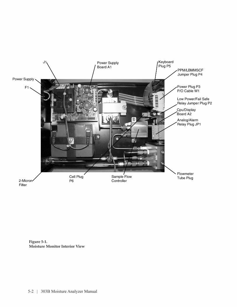
Figure 5-1.Moisture Monitor Interior View
Maintenance | 5-3
Parts Replacement
Flow Meter Tubes (Figure 5-1)
1. Turn off power using front panel switch and disconnect the unit from the power source.
2. Shut off sample flow at the source and purge the line. Shut off purge.
3. Remove the screws and lift off the cover.
4. Disconnect the “U” tube between the top fittings.
5. Remove the two screws and the plastic cover from the assembly.
6. With a hex wrench, loosen the plug over the glass tube in the assem-bly top and remove the tube. Using a piece of tape on the glass makes replacement easier.
7. Be sure the glass tube is centered on the top and bottom seals and the grounding wire is around the tube before tightening the top plug.
Do not tighten the screws on the plastic cover or the cover might break.
Flow Controller (Figure 5-1)
1. To gain access, perform steps 1, 2 and 3 above under Flow Meter Tubes section.
2. Loosen the two tubing ferrule nuts at the flow controller and discon-nect the lines.
3. Remove the mounting nuts and lift out the flow controller and brack-et.
4. Remove the screw and remove the flow controller from the bracket.
Power Supply PC Board (Figure 5-1)
1. To gain access, perform steps 1, 2 and 3 above under Flow Meter Tubes section.
2. Loosen the screws and remove the power-in wires from J1; remove
NOTE

5-4 | 303B Moisture Analyzer Manual
the ribbon plug from J2.
3. Remove the four mounting screws and board from its mounting.
Main AC Fuse (Figure 5-1)
1. To gain access, perform steps 1, 2 and 3 above under Flow Meter Tubes section.
2. Locate fuse F1 on the power supply board near the transformer.
3. Lift out F1 and test with an ohm meter. If open, use appropriate fuse type stated in Section 5.
4. If fuse blows again, replace power supply pc board.
Battery (Figure 5-1)
1. To gain access, perform steps 1, 2 and 3 above under Flow Meter Tubes section.
2. Remove the wire terminals from the battery. Note that red wire is on + terminal.
3. Remove the two bracket nuts, move the bracket to the side, and lift out the battery.
4. If new battery does not fix problem, check polarity. Allow 24 hours for initial charge.
On battery replacement, use only AMETEK 303020001, nominal 12Vdc @ 5 Amp hour.
CPU/Display Board
1. To gain access, perform steps 1, 2 and 3 above under Flow Meter Tubes section.
2. Remove connectors P6, P1, P3, and P5.
3. Remove the three mounting nuts and the board.
!WARNING

Maintenance | 5-5
Testing
Leak Test
The following test will assure that the monitor is free from leaks that will interfere with proper operation.
1. Cap off the GAS OUT fitting.
2. Attach a 0 to 1000-kPa (150-psi) leak-free pressure gauge and leak-free shutoff valve to the GAS IN fitting (the gauge must be between the valve and the monitor).
3. Connect a regulated source of clean, dry, pressurized gas (N2, instru-ment air, etc.) to the shutoff valve. With the valve closed, adjust gas pressure to 700 kPa (100 psi) gauge. Slowly open the valve and allow pressure in the monitor to equilibrate. Ensure that the monitor pres-sure gauge reads 700 kPa (100 psi) and adjust if necessary. Close the shutoff valve and disconnect the gas source from the IN fitting.
4. After 60 minutes, note the pressure. It should not drop more than 34 kPa (5 psi) gauge.
5. If pressure test is satisfactory, remove the gauge, shutoff valve, and caps. Proceed to other tests in this section.
6. If gauge pressure has dropped more than 14 kPa (2 psi), repressurize to 700 kPa (100 psi) and check all connections for leaks with a soap solution. Repair leaks as needed.
7. Repeat steps 3 through 6 until a gauge pressure drop of less than 14 kPa (2 psi) is noted.
8. Remove pressure gauge, shutoff valve, and caps. Proceed to other tests in this section.
Gas Flow Operational Test
1. Check all fittings for tightness.
If you use a hazardous gas, be sure the bubble-o-meter is vented to a safe place.
2. Connect a flow device such as a bubble-o-meter or a flow meter to the GAS OUT fitting. Since it is more accurate, a bubble-o-meter is pre-ferred.
!WARNING

5-6 | 303B Moisture Analyzer Manual
3. Adjust sample gas pressure to about 3.4 bar (50 psi) gauge.
4. Vary sample gas pressure between 1.4 and 6.9 bar (20 and 100 psi) gauge and check that flow does not vary more than ±5 percent.
Power Supply Voltage Tests
1. Press POWER key (LED ON).
2. Disconnect the ribbon cable plug from power supply board connector J2.
3. Measure the voltages shown in figure 4-3 on each J2 pin using small clip leads. If any voltage is > ±10 percent, replace the power supply board.
4. If all voltages are ok, connect the ribbon cable plug and do a:
• Cell Test to check the 50-volt supply. Unplug the cell at JP6. If the displayed voltage is not between 47 and 53, replace the power supply board.
• Electrical Test to check the 5-volt supply. If the displayed voltage is not between 4.7 and 5.3, replace the power supply board.
• Output Test to check the 4 to 20-mA output. Disconnect the leads from JP1-1 and -2 and attach a dc voltmeter in their place (+ to -1). If the volt-meter does not read between 13 and 17, replace the cpu/display board.
Troubleshooting
Troubleshooting Table 4-1 localizes a faulty assembly. It is not intended to isolate a faulty component.
Memory Errors Er01 and Er02
Both these displayed errors are associated with the Analog Range, Alarm Setpoint, Gain, Offset, and Factory Gain variable parameters stored in electrically erasable read-only memory (EEPROM). EEPROM retains pa-rameter values on power shut-down so they can be enabled on power-up. A coding scheme — checksum — is stored with the data to make sure the data does not change during storage.
On power-up, the stored parameters are read and checked against the checksum. If there is a problem with checksum reading, read error Er01

Maintenance | 5-7
is displayed. If there is a problem storing values during parameter value en-tering, write error Er02 is displayed. Only the Analog Range param-eter entry does not give a display feedback when it is stored correctly. For either error, power-down and reenter the parameters as directed in the procedures on pages 5-7 and 5-8.
Display and LED Test
On power-up, all LED’s and display segments sequence through the set pattern shown in the following chart at a half-second-per-step rate. The LED’s will flash ON and OFF at about a four-per-second rate.
Observing the sequence closely lets you see if any LED or segment is not working. Although the POWER and AC POWER LED’s are not part of the sequence, they will be ON whenever the monitor is connected to an ac supply and the unit is powered up.
Flashing LED Positions
STEP DISPLAY CELL ELEC STAND ALARM ANALOG RANGE
TEST TEST BY Bottom to Top
1 8 . 8 . 8 . 8 O N O N O N O N O N O N O N O N
2 0 0 0 0 O N
3 1 1 1 1 O N O N
4 2 2 2 2 O N O N O N
5 3 3 3 3 O N O N O N O N
6 4 4 4 4 O N O N O N O N O N
7 5 5 5 5 O N O N O N O N O N O N
8 6 6 6 6 O N O N O N O N O N O N O N
9 7 7 7 7 O N O N O N O N O N O N O N O N
1 0 8 8 8 8 O N O N O N O N O N O N O N O N
1 1 9 9 9 9 O N O N O N O N O N O N O N O N
1 2 P x . x x O N O N O N O N O N O N O N O N
5-8 | 303B Moisture Analyzer Manual
In step 12, P x.xx represents your software revision number, which can be helpful to identify software upgrades. This should be the same number written on the cpu/display board cpu PROM.
Parameter Settings
Offset
Offset subtracts from the moisture readings.
1. Press the POWER key (LED OFF). Hold the STANDBY key (LED ON) and press the POWER key (LED ON) until the STANDBY, +, and – LED’s flash.
2. Press the + or – key to increment or decrement the display to the desired valve.
3. When the desired value is displayed, press OFFSET to store the value; ProG will be displayed until the value is stored, followed by the normal LED/display test.
If the ALARM, CELL TEST, 0-1000 (50), 0-2000 (100), or DISPLAY LIGHT key is pressed during the routine, the new value is not stored and normal moisture measuring begins.
Gain
Gain adjustment enables a value to be entered to compensate for non-standard ranges or flow limitations.
1. Press the POWER key (LED OFF). Hold the ELEC TEST key (LED ON) and press the POWER key (LED ON) until the STANDBY, +, and – LED’s flash.
2. Press the + or – key to increment or decrement the display to the de-sired valve.
3. When the desired value is displayed, press GAIN to store the value; ProG will be displayed until the value is stored, followed by the nor-mal LED/display test.
NOTE

Maintenance | 5-9
If the ALARM, CELL TEST, 0-1000 (50), 0-2000 (100), or DISPLAY LIGHT key is pressed during the routine, the new value is not stored and normal moisture measuring begins.
Factory A/D Gain
Factory A/D gain linearizes the cpu/display board to the moisture cell.
1. Press the POWER key (LED OFF). Hold both ELEC TEST and STAND-BY keys (LED’s ON) and press the POWER key (LED ON) until the STANDBY, ELEC TEST, + and - LEDs flash.
2. Press the + or - key to increment or decrement the display to the de-sired value.
3. When the desired value is displayed, press STANDBY to store the value; ProG will be displayed until the value is stored, followed by the
If the ALARM, CELL TEST, 0-1000 (50), 0-2000 (100), or DISPLAY LIGHT key is pressed during the routine, the new value is not stored and normal moisture measuring begins.
NOTE
NOTE
5-10 | 303B Moisture Analyzer Manual
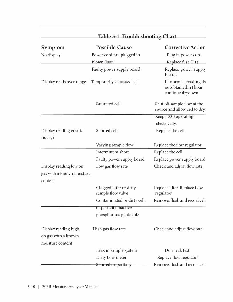
Table 5-1. Troubleshooting Chart
Symptom Possible Cause Corrective ActionNo display Power cord not plugged in Plug in power cord Blown Fuse Replace fuse (F1) Faulty power supply board Replace power supply board.Display reads over range Temporarily saturated cell If normal reading is not obtained in 1 hour continue drydown. Saturated cell Shut off sample flow at the source and allow cell to dry. Keep 303B operating electrically.Display reading erratic Shorted cell Replace the cell (noisy) Varying sample flow Replace the flow regulator Intermittent short Replace the cell Faulty power supply board Replace power supply boardDisplay reading low on Low gas flow rate Check and adjust flow rategas with a known moisture content Clogged filter or dirty Replace filter. Replace flow sample flow valve regulator Contaminated or dirty cell, Remove, flush and recoat cell or partially inactive phosphorous pentoxide
Display reading high High gas flow rate Check and adjust flow rateon gas with a known moisture content Leak in sample system Do a leak test Dirty flow meter Replace flow regulator Shorted or partially Remove, flush and recoat cell

Maintenance | 5-11
shorted cell
Symptom Flow slow or erratic
AC POWER LED does not light with unit connected to ac supply
After power up, display shows Er02
After power up, display
shows Er01
Display flashing 9999
ELEC TEST, +, and - LEDs flashing
STANDBY, +, and - LEDs flashing
ELEC TEST, STANDBY, +, and – LEDs flashing
ALARM, +, and – LEDs flashing
STANDBY (display blank) LEDs flashing
Possible CauseClogged filter or flow meter
Blown fuse F1
Check sum read error detected during alarm, analog range, gain offset or factory gain read
Checksum write error detected during alarm, analog range, gain offset or factory gain write
Gain or moisture level too high
In gain adjust mode; dis-play shows offset value
In offset adjust mode; display shows offset value
In factory gain adjust mode; display shows fac-tory gain value
In alarm adjust mode; dis-play shows alarm setpoint
In standby - battery power save mode
Corrective ActionReplace filter or flow regulator
Replace fuse
Reenter parameter values as directed in procedure on pages 5-7 and 5-8.
Reenter parameter values as directed in procedure on pages 5-7 and 5-8.
Do a cell test for high mois-ture level, or reset the gain or factory gain values as directed in procedures on page 5-9.
Press any key to exit with-out saving displayed val-ue; press ELEC TEST to exit and save value.
Press any key to exit with-out saving displayed value; press STANDBY to exit and save value.
Press any key to exit with-out saving displayed val-ue; press ELEC TEST and STANDBY to exit and save value.
Press any key to exit with-out saving displayed val-ue; press ALARM to exit and save value.

5-12 | 303B Moisture Analyzer Manual
Press STANDBY to return to moisture analysis.
SymptomELEC TEST and any one ANALOG RANGE LEDs flashing
CELL TEST and any one ANALOG RANGE LEDs flashing
Analyzer will not turn off in battery mode
Possible CauseIn electrical test mode
In cell test mode
Low Battery
Corrective ActionPress ELEC TEST to exit.
Press CELL TEST to exit.
Recharge the battery by running the analyzer in the AC power mode.

Service and Parts | 6-1
SERVICE AND PARTS
Parts Ordering Information
This section lists parts AMETEK considers practical to stock and supply for replacement. The parts are listed in Table 6-1 and identified by reference designation or item numbers in Figures 6-1, 6-2, and 5-1.
To obtain replacement parts, contact any of the regional offices listed below and include the part number and description. To ensure that you receive the correct part for your monitor, be sure you include the instrument type and its serial and/or model number.
USA - HEADQUARTERS150 Freeport RoadPittsburgh, PA 15238Phone: 412-828-9040Fax: 412-826-0399
USA - Delaware455 Corporate BoulevardNewark, Delaware 19702Phone: 302-456-4400 Fax: 302-456-4444
USA - Texas9750 Whithorn DriveHouston, Texas 77095Phone: 713-466-4900Fax: 713-489-1924
CANADA2876 Sunridge Way N.E.Calgary, Alberta T1Y 7H9Phone: 403-235-8400 Fax: 403-248-3550
GERMANYPostfach 2165D-40644 Meerbusch
OR
Rudolf-Diesel Strasse 16D-40670 MeerbuschPhone: 49-21-59-9136-0Fax: 49-21-59-9136-39
FRANCERond Point de l’épine des champsBuroplus Bat D78990 ELANCOURTPhone: 33 1 30 68 89 20Fax: 33 1 30 68 89 29
CHINARoom 912, Metro TowerNo. 30 Tian Yao Qiao RoadShanghai 200030 P.R. ChinaTel: 86-21-6426-8111Fax: 86-21-6426-7818
6-2 | 303B Moisture Analyzer Manual
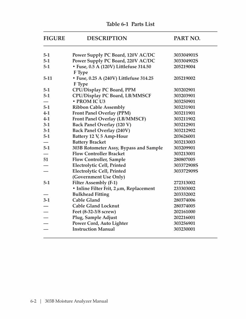
Table 6-1 Parts List
FIGURE DESCRIPTION PART NO.
5-1 Power Supply PC Board, 120V AC/DC 303304901S5-1 Power Supply PC Board, 220V AC/DC 303304902S5-1 • Fuse, 0.5 A (120V) Littlefuse 314.50 205219004 F Type5-11 • Fuse, 0.25 A (240V) Littlefuse 314.25 205219002 F Type5-1 CPU/Display PC Board, PPM 3032029015-1 CPU/Display PC Board, LB/MMSCF 303203901— • PROM IC U3 3032509015-1 Ribbon Cable Assembly 3032319014-1 Front Panel Overlay (PPM) 3032119014-1 Front Panel Overlay (LB/MMSCF) 3032119023-1 Back Panel Overlay (120 V) 3032129013-1 Back Panel Overlay (240V) 3032129025-1 Battery 12 V, 5 Amp-Hour 203626001— Battery Bracket 3032130035-1 303B Rotometer Assy, Bypass and Sample 303209901— Flow Controller Bracket 30321300151 Flow Controller, Sample 280807005— Electrolytic Cell, Printed 303372908S— Electrolytic Cell, Printed 303372909S (Government Use Only) 5-1 Filter Assembly (F-1) 272313002 • Inline Filter Frit, 2 µm, Replacement 233303002— Bulkhead Fitting 2033320023-1 Cable Gland 280374006— Cable Gland Locknut 280374005— Feet (8-32-3/8 screw) 202161000— Plug, Sample Adjust 202216001— Power Cord, Auto Lighter 303256901— Instruction Manual 303230001
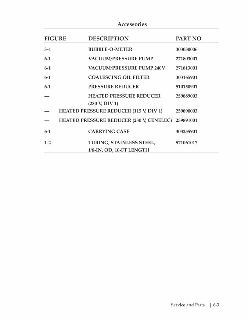
Service and Parts | 6-3
Accessories
FIGURE DESCRIPTION PART NO.
3-4 BUBBLE-O-METER 303030006
6-1 VACUUM/PRESSURE PUMP 271803001
6-1 VACUUM/PRESSURE PUMP 240V 271813001
6-1 COALESCING OIL FILTER 303165901
6-1 PRESSURE REDUCER 510150901
— HEATED PRESSURE REDUCER 259889003
(230 V, DIV 1)
— HEATED PRESSURE REDUCER (115 V, DIV 1) 259890003
— HEATED PRESSURE REDUCER (230 V, CENELEC) 259891001
6-1 CARRYING CASE 303255901
1-2 TUBING, STAINLESS STEEL, 571061017
1/8-IN. OD, 10-FT LENGTH
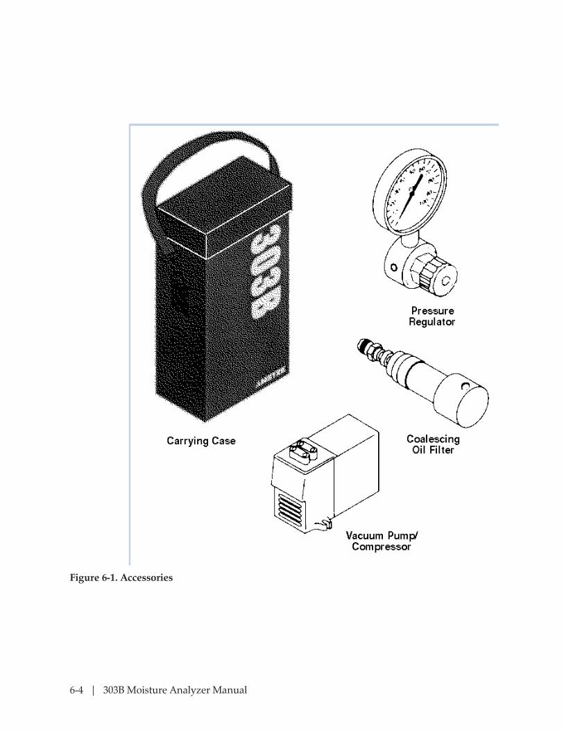
6-4 | 303B Moisture Analyzer Manual
Figure 6-1. Accessories

Appendix-A | A-1
Notes:
1. The graph is based on standard atmospheric pressure. See figure C-1 for relationship at other pressures.
2. The graph relates absolute moisture levels, as obtained on the 303B, to dew point in either °F or °C.
3. To convert ppm to lb/mmscf, multiply the ppm value by 0.0476.
Appendix A
Figure A-1.Conversion Chart (PPm H20 to Dew Point)

A-2 | 303B Moisture Analyzer Manual
This page intentionally left blank.
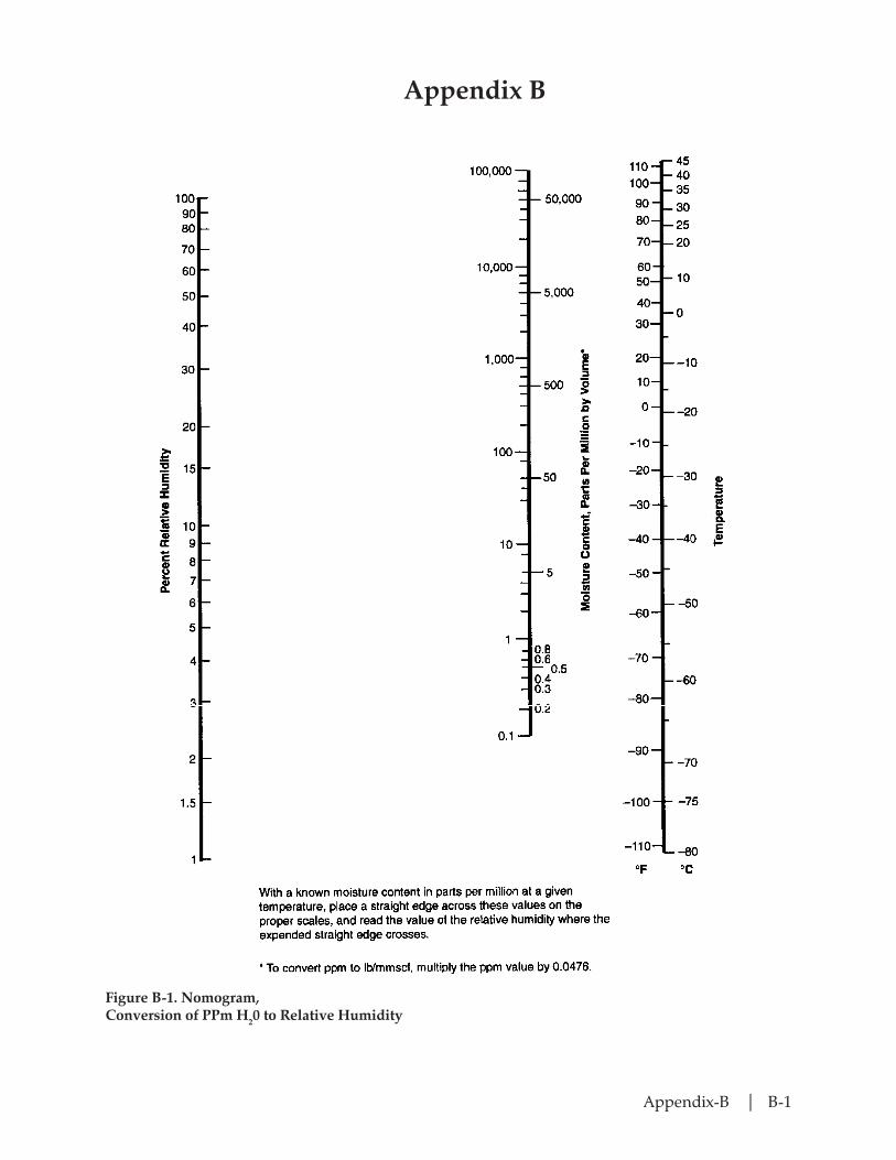
Appendix-B | B-1
Appendix B
Figure B-1. Nomogram,Conversion of PPm H20 to Relative Humidity

B-2 | 303B Moisture Analyzer Manual
This page intentionally leftr blank.

Appendix-C | C-1
Appendix C
Figure C-1. Nomogram,Determination of Dew Point with Pressure.

C-2 | 303B Moisture Analyzer Manual
This page intentionally left blank.

Appendix-D | D-1
Appendix D
lb/MMscf Pounds of water per million cubic feet of sample. (A temperature must be specified.)
Electrolytic Cell Cell with two electrodes coated with a phospho-rus pentoxide desiccant. Water vapor is absorbed by the desiccant and electrolyzed by current passing through the cell.
Saturated Cell A condition where the phosphorus pentoxide coating has absorbed so much water that cell drying is required.
Flooded Cell A condition of extreme saturation. The phospho-rus pentoxide coating is dissolved, so that re-coating is necessary.
Water Hang-Up Water trapped or absorbed onto the system walls or fittings.
Tramp Water Water which has entered a sample stream from a source other than the source being sampled.
System Equilibrium A system condition where water is absorbed onto the system walls at the same rate as it is given off.
Entrained Dirt Dirt carried by a sample stream.
Dew Point (H2O) Temperature at which water vapor begins to de- posit as liquid.
System Response Time Sample system volume divided by the flow.
Speed of Response The time for the moisture analyzer to reach 63 percent of its final reading after a step change in moisture content.
XX_XX In mathematical term s, a single variable using two or more words.

D-2 | 303B Moisture Analyzer Manual
This page intentionally left blank.

Appendix-E | E-1
Appendix E
Divide desired flow rate by the following correction factors to obtain proper flow meter setting
Flow meter Correction Factors (Approximate)
Argon 0.85
Butadiene 0.73
Butane 0.71
Carbon Monoxide 1.01
Ethane 0.98
Ethylene 1.02
F-22 0.58
F- 12 0.49
134A 0.53
Helium 2.69
Isobutane 0.71
Isobutylene 0.72
Methane’s 1.35
Nitrogen 1.01
Oxygen 0.95
Propane 0.81
Propylene 0.83
Mole weight of gas X = -------------------------------------- 28.95 (Mole weight of air) CorrectionFactor=√1/X

E-2 | 303B Moisture Analyzer Manual
This page intentionally left blank.