Bedside Monitor - Frank's Hospital Workshop
315
0614-900685U Bedside Monitor BSM-6301/BSM-6501/BSM-6701 Operator’s Manual BSM-6000 series BSM-6301A BSM-6301K BSM-6501A BSM-6501K BSM-6701A BSM-6701K
-
Upload
khangminh22 -
Category
Documents
-
view
3 -
download
0
Transcript of Bedside Monitor - Frank's Hospital Workshop

0614-900685U
Bedside MonitorBSM-6301/BSM-6501/BSM-6701
Operator’s Manual
BSM-6000 seriesBSM-6301ABSM-6301KBSM-6501ABSM-6501KBSM-6701ABSM-6701K
In order to use this product safely and fully understand all its functions, read this manual before using the product.
Keep this manual near the instrument or in the reach of the operator and refer to it whenever the operation is unclear.
This product stores personal patient information. Manage the information appropriately.
Patient names on the screen shots and recording examples in this manual are fictional and any resemblance to any person living or dead is purely coincidental.
The contents of this manual are subject to change without notice.
If you have any comments or suggestions on this manual, please contact us at: www.nihonkohden.com
Copyright NoticeThe entire contents of this manual are copyrighted by Nihon Kohden. All rights are reserved. No part of this document may be reproduced, stored, or transmitted in any form or by any means (electronic, mechanical, photocopied, recorded, or otherwise) without the prior written permission of Nihon Kohden.
Trademark
The mark printed on the SD card that is used in this instrument is a trademark. The company name and model name are trademarks and registered trademarks of each company.
Operator’s Manual BSM-6000 C.1
ContentsAbout this Manual ......................................................... 1
Related Documentation ................................................ 1
Intended Purpose ......................................................... 2
Indications for Use ................................................... 3
Precautions ................................................................... 4
General Handling Precautions ................................ 4
EMC Related Caution .............................................. 4
Other Caution .......................................................... 6
Responsibility of the Manufacturer ............................... 6
Conventions Used in this Manual and Instrument ........ 7
Warnings, Cautions and Notes ................................ 7
Text Conventions ..................................................... 7
Explanations of the Symbols in this Manual and
Instrument .................................................................... 8
General Safety Information ......................................... 11
Panel Description ....................................................... 14
MU-631R Main Unit ............................................... 14
MU-651R/MU-671R Main Unit .............................. 16
AY-631P/AY-633P/AY-651P/AY-653P/AY-660P/
AY-661P/AY-663P/AY-671P/AY-673P Input Unit ..... 18
BSM-1700 series Bedside Monitor ........................ 20
AA-672P/AA-674P Smart Expansion Unit ............. 21
Installation .................................................................. 22
General .................................................................. 22
Grounding the Monitor ...................................... 23
Environment for External Instruments .............. 23
Warnings and Cautions for Connecting the
Monitor to a Network ........................................ 24
Inserting and Removing the Battery Packs ........... 25
Inserting the Battery Pack ................................ 25
Removing the Battery Pack .............................. 26
Inserting and Removing the AY-600P series
Input Unit or BSM-1700 series Bedside
Monitor .................................................................. 27
Inserting the Input Unit ..................................... 27
Removing the Input Unit ................................... 27
Loading Recording Paper ...................................... 28
Turning the Monitor On or Off ..................................... 29
Turning the Monitor On .......................................... 29
Check Before Turning On the Power ................ 29
Check After Turning On the Power and
During Monitoring ............................................. 30
Power and Battery Status Indications............... 31
Battery Pack Handling and Operation .............. 32
Charging the Battery Pack ............................... 34
Stored Data Status at Power On ........................... 34
Monitor Status on Power Interruption .................... 35
Turning the Monitor Off .......................................... 35
Check After or Before Turning the Power
Off ..................................................................... 35
Basic Operation .......................................................... 36
Using the Hard Keys on the Bedside Monitor
and Touch Screen .................................................. 36
Using the Remote Control ..................................... 36
Using the Mouse ................................................... 36
Home Screen Description........................................... 37
Settings for the Home Screen ............................... 38
Trendgraph on the Home Screen (Current
Trendgraph) ........................................................... 39
OCRG ............................................................... 39
Freezing Waveforms .............................................. 39
Using the Timer ..................................................... 39
Car Seat Challenge ............................................... 39
Using Sleep Mode ................................................. 40
MENU Window Description ........................................ 41
Changing Settings ...................................................... 42
Administrator Settings ........................................... 42
Changing Parameter Settings and Other
Settings ................................................................. 42
Changing Settings ............................................ 42
Changing Settings on the VOLUME
Window ............................................................. 43
Admitting/Discharging Patient..................................... 44
Admitting a Patient ................................................ 44
Discharging a Patient ............................................ 46
Stored Data Status and Screen Transition for
Admitting Patient ................................................... 47
Using Transport Function in a Monitor Network .......... 49
Input Unit ............................................................... 49
Transport Function ................................................. 49
Warnings and Cautions for Transport ............... 50
WLAN Transport .................................................... 52
Using Transport Function with a Defibrillator .............. 53
Alarms ........................................................................ 54
Alarm Types and Levels ......................................... 54
Alarm Control Marks.............................................. 56
Flow of Alarm Function .......................................... 56
Silencing/Suspending Alarms ................................ 57
Silencing Alarms .............................................. 57
Suspending Alarms .......................................... 57
Canceling Technical Alarms .................................. 60
Alarm Sound Volume ............................................. 60

C.2 Operator’s Manual BSM-6000
Alarm Recording .................................................... 60
Alarm Setting ......................................................... 60
Changing Vital Sign Upper/Lower Alarm
Limits ................................................................ 62
Changing the Arrhythmia Alarm Settings ......... 65
Alarm Escalation ................................................... 66
Interbed Alarm ....................................................... 67
Review Windows......................................................... 68
General .................................................................. 68
Event Bar .......................................................... 69
TREND Window .................................................... 70
GRAPH 1, GRAPH 2, GRAPH 3 Page ............. 70
TABLE 1, TABLE 2, TABLE 3 Page ................... 71
NIBP TREND Page .......................................... 72
HEMO TREND Page ........................................ 73
Adding the Acquired Data to the
Hemodynamics Table ....................................... 73
LUNG TREND Page ......................................... 74
RECALL Window ................................................... 75
ARRHYTH HISTORY Page .............................. 75
ALARM HISTORY Window .................................... 76
ALARM HISTORY Page ................................... 76
FULL DISC Window .............................................. 77
FULL DISC Page .............................................. 77
ST Window ............................................................ 79
ST INTERVAL Page ......................................... 79
OCRG Window ...................................................... 80
aEEG Window ....................................................... 81
12 LEAD/12 LEAD ANALYSIS Windows .................... 82
General .................................................................. 82
12 LEAD ANALYSIS Window ................................ 83
Performing 12 Lead ECG Interpretation ........... 83
12 LEAD Window .................................................. 85
Viewing the 12 Lead Analysis Result ............... 85
DRUG/LUNG FUNCTION Windows ........................... 87
DRUG Window ...................................................... 87
LUNG FUNCTION Window ................................... 89
Recording ................................................................... 91
Recording Modes .................................................. 91
When More than One Recording Modes is
Triggered .......................................................... 91
Changing Recording Settings ................................ 91
Selecting Recording Waveforms ...................... 92
Changing Recording Speed ............................. 92
Selecting Recording Interval for Periodic
Recording ......................................................... 92
Turning Alarm Recording On or Off .................. 92
INTERBED Window .................................................... 93
Registering/Removing Interbed Beds .................... 93
Displaying the Interbed Bed Data .......................... 94
Interbed Alarm Function ........................................ 96
Interbed Alarm Setting ..................................... 96
Monitoring Parameters ............................................... 97
ECG ....................................................................... 97
Preparation ....................................................... 97
Monitoring Arrhythmia .................................... 100
Changing ECG Settings ................................. 104
Respiration .......................................................... 111
Preparation ..................................................... 111
Changing Respiration Settings ....................... 112
CO2 ..................................................................... 114
Preparation ..................................................... 115
Changing CO2 Settings .................................. 118
Inspection of Measuring Accuracy ................. 121
Use with Volatile Anesthetic Agents ............... 121
SpO2 with Nihon Kohden Probes (AY-660P/
AY-661P/AY-663P/AY-671P/AY-673P/
BSM-1763/BSM-1773) ........................................ 122
Silencing SpO2 Alarm ..................................... 123
Preparation ..................................................... 123
Changing SpO2 Settings ................................. 126
SpO2 with Nellcor Probes (AY-651P/AY-653P/
BSM-1753) .......................................................... 130
Silencing SpO2 Alarm ..................................... 131
Preparation ..................................................... 131
Changing SpO2 Settings ................................. 134
SpO2 with Masimo Probes (AY-631P/AY-633P/
BSM-1733) .......................................................... 137
Silencing SpO2 Alarm ..................................... 138
Preparation ..................................................... 139
Changing SpO2 Settings ................................. 142
NIBP .................................................................... 146
Preparation ..................................................... 146
Changing NIBP Settings ................................. 148
Starting and Stopping NIBP Measurement .... 151
IBP ....................................................................... 156
Preparation ..................................................... 156
Connecting Cables to the Unit ........................ 156
Assembling the Transducer ............................ 157
Adjusting Zero Balance .................................. 158
The CHECK ZERO Page ............................... 159
Changing IBP Settings ................................... 159
Temperature ........................................................ 164
Preparation ..................................................... 164
Using the Insulation Pad ................................ 165
Changing Temperature Settings ..................... 165
BIS ....................................................................... 167
Preparation ..................................................... 167
Changing the BIS Settings ............................. 171
Cardiac Output .................................................... 174

Operator’s Manual BSM-6000 C.3
Preparation ..................................................... 174
Measuring the Pulmonary Capillary Wedge
Pressure ......................................................... 175
Measuring Cardiac Output ............................. 176
Deleting the Data from the CO Table .............. 180
Adding the Acquired Data to the HEMO
TREND Page of the TREND Window ............. 181
GAS ..................................................................... 182
Preparation ..................................................... 182
Changing Gas Settings .................................. 182
Inspection of Measuring Accuracy ................. 185
O2 ....................................................................... 186
Preparation ..................................................... 186
Changing O2 Settings ..................................... 187
CCO .................................................................... 188
Preparation ..................................................... 188
Changing the CCO Settings ........................... 189
Other Parameters ................................................ 191
Screen Messages ..................................................... 194
Troubleshooting ........................................................ 214
Monitoring ............................................................ 214
Network ............................................................... 215
Transport in a Monitor Network ........................... 215
Remote Control ................................................... 216
Recording ............................................................ 217
Printing ................................................................ 217
ECG ..................................................................... 217
Respiration .......................................................... 218
Impedance Method ......................................... 218
Thermistor Method ......................................... 219
CO2 ..................................................................... 219
Mainstream Method ........................................ 219
Sidestream Method ........................................ 220
When Using Microcap® Monitor or
Micropod™ Module ........................................ 220
SpO2 ................................................................... 221
When Using Nellcor or Masimo Pulse
Oximeter ......................................................... 221
NIBP .................................................................... 222
IBP ....................................................................... 223
Temperature ........................................................ 223
BIS ....................................................................... 223
When Using BIS Processor/BISx ................... 223
When Using BIS Monitor ................................ 223
Cardiac Output .................................................... 224
GAS ..................................................................... 224
When Using AG-920R Multigas Unit .............. 224
When Using GF-110PA Multigas Unit or
GF-120PA Multigas/Flow Unit ........................ 224
When Using GF-210R Multigas Unit or
GF-220R Multigas/Flow Unit .......................... 225
O2 ....................................................................... 226
Ventilation ............................................................ 227
TOF ..................................................................... 227
CCO .................................................................... 227
When Using APCO/IBP Processor ................. 227
When Using PiCCO Monitor ........................... 228
When Using Other CCO Monitors .................. 228
FLOW/Paw .......................................................... 229
When Using GF-120PA Multigas/Flow Unit .... 229
When Using GF-220R Multigas/Flow Unit ...... 229
EEG ..................................................................... 230
tcPO2/tcPCO2 ...................................................... 230
rSO2 .................................................................... 231
Anesthesia ........................................................... 231
Transmitter ........................................................... 231
12 Lead ECG ....................................................... 231
aEEG ................................................................... 231
Maintenance ............................................................. 232
MU-631R, MU-651R and MU-671R Main Unit .... 232
Cleaning and Disinfecting the Main Unit ........ 232
Cleaning the Touch Screen ............................ 233
Disposing of the Main Unit ............................. 234
WS-671P Recorder Module ................................ 234
Cleaning the Thermal Head ........................... 234
Cleaning the Sensors ..................................... 234
Disposing of the Recorder Module ................. 234
AY Series Input Unit and AA-672P/AA-674P
Smart Expansion Unit.......................................... 235
Cleaning and Disinfecting the Units ............... 235
Disposing of the Units .................................... 235
BSM-1700 series Bedside Monitor ...................... 235
SB-671P Battery Pack ......................................... 235
Battery Lifetime .............................................. 235
Replacing the Batteries .................................. 235
Disposing of Batteries .................................... 235
RY-910P Remote Controller ................................ 235
Cleaning and Disinfecting the Remote
Controller ........................................................ 235
Disposing of the Remote Controller ............... 235
Replacing the Batteries .................................. 235
Disposing of Batteries .................................... 235
QF series Interface and IF series
Communication Cable ......................................... 235
Cleaning and Disinfecting the Interface and
Communication Cable .................................... 235
Disposing of the Interface and
Communication Cable .................................... 236

C.4 Operator’s Manual BSM-6000
Leads, Cables and Cords .................................... 236
Cleaning the Leads, Cables and Cords .......... 236
Disinfecting the Leads, Cables and Cords ..... 236
Disposing of Leads, Cables and Cords .......... 236
Electrodes, Probes, Cuffs, Thermistors,
Transducers, Catheters and Other
Consumables....................................................... 236
Periodic Inspection .............................................. 236
Safety Information for Maintenance on
Optional Units ...................................................... 237
AG-920R, GF-110PA or GF-210R Multigas
Unit and GF-120PA or GF-220R Multigas/
Flow Unit ........................................................ 237
AG-400R CO2 Unit ......................................... 238
AE-918P Neuro Unit ....................................... 238
Specifications ........................................................... 239
Measuring Parameters ........................................ 239
Influence on Measuring Accuracy by
Electrosurgery/Defibrillation/Electrostatic
Discharge ............................................................ 239
Display ................................................................. 239
Alarm ................................................................... 240
Alarm Delay Time ................................................ 241
ECG ..................................................................... 242
Respiration (Transthoracic impedance
pneumography) ................................................... 244
SpO2 ................................................................... 244
Non Invasive Blood Pressure, NIBP .................... 247
Multi Socket ......................................................... 248
Invasive Blood Pressure, IBP .............................. 248
Temperature ........................................................ 249
Carbon Dioxide, CO2 (Mainstream method) ........ 249
Inspired Oxygen Fractional Concentration, O2 ... 250
Cardiac Output, CO ............................................. 250
Respiration (Thermistor method) ......................... 251
Bispectral Index, BIS ........................................... 251
ECG/BP Output ................................................... 252
RGB Socket (when QI-631P or QI-671P is
connected) ........................................................... 252
RS-232C Socket (when QI-631P or QI-671P is
connected) ........................................................... 253
Alarm Socket (when QI-632P or QI-671P is
connected) ........................................................... 253
When WS-671P Recorder Module is
Connected ........................................................... 253
When ZS-900P Transmitter is Connected ........... 253
Gas ...................................................................... 253
Carbon Dioxide, CO2 (Sidestream method) ......... 256
FLOW/Paw .......................................................... 257
EEG ..................................................................... 257
CCO .................................................................... 258
Battery (SB-671P Battery Pack) .......................... 258
Power Requirement ............................................. 259
Clock Accuracy .................................................... 259
Environment ........................................................ 259
Mechanical Strength ............................................ 259
Electromagnetic Compatibility ............................. 259
Safety Standard ................................................... 260
Dimensions and Weight (approximate) ................ 261
Electromagnetic Emissions ................................. 262
Electromagnetic Immunity ................................... 263
Recommended Separation Distances between
Portable and Mobile RF Communications
Equipment ........................................................... 265
System Composition for EMC Test ...................... 266
Factory Default Settings ........................................... 267
Event Bar ............................................................. 267
TREND Window .................................................. 268
RECALL Window ................................................. 271
FULL DISC Window ............................................ 271
ST Window .......................................................... 271
OCRG Window .................................................... 272
aEEG Window ..................................................... 272
ADMIT DISCHARGE Window ............................. 272
ALARM LIMITS Window ...................................... 273
Vital Signs Alarms .......................................... 273
Arrhythmia Alarms .......................................... 278
DATE Window ...................................................... 279
VOLUME Window ................................................ 279
DISPLAY Window ................................................ 279
RECORD Window ............................................... 279
ECG Window ....................................................... 280
RESP/CO2 Window ............................................. 281
SpO2 Window ...................................................... 281
NIBP Window ...................................................... 282
PRESS Window ................................................... 283
TEMP Window ..................................................... 284
BIS Window ......................................................... 284
CO Window ......................................................... 284
GAS Window ....................................................... 285
O2 Window ........................................................... 286
VENT Window ..................................................... 286
CCO Window ....................................................... 286
FLOW/Paw Window ............................................. 287
EEG Window ....................................................... 288
ANALOG Window ................................................ 289
rSO2 Window ....................................................... 289
12 LEAD ANALYSIS Window .............................. 289

Operator’s Manual BSM-6000 C.5
DRUG Window .................................................... 290
LUNG FUNCTION Window ................................. 292
INTERBED Window ............................................. 292
CAR SEAT CHALLENGE Window ...................... 292
Standard Accessories .............................................. 293
MU-631RA/MU-651RA/MU-671RA Main Unit ..... 293
MU-631RK/MU-651RK/MU-671RK Main Unit ..... 293
Options/Consumables .............................................. 294
Accessory Set ..................................................... 294
MU-631RA/MU-651RA/MU-671RA Main Unit ..... 294
MU-631RK/MU-651RK/MU-671RK Main Unit ..... 295
Units and Modules ............................................... 296
Network ............................................................... 297
Interfaces and Cables for External
Instruments .......................................................... 297
Cart and Attaching Parts ..................................... 299
For ECG and Respiration (Impedance Method)
Monitoring ............................................................ 299
For Respiration Monitoring (Thermistor
Method) ............................................................... 300
For CO2 Monitoring (Mainstream Method) ........... 300
For SpO2 Monitoring ............................................ 301
For NIBP Monitoring ............................................ 302
For IBP Monitoring............................................... 303
For Temperature Monitoring ................................ 304
For BIS Monitoring (Using the BIS Processor/
BISx) .................................................................... 305
For CO Monitoring ............................................... 305
For O2 Monitoring ................................................ 305
For CCO Monitoring ............................................ 305
For CO2 Sidestream Monitoring ........................... 305
For BIS Monitoring (Using the BIS Monitor) ........ 306
For Anesthetic Agent Monitoring ......................... 306
For FLOW/Paw Monitoring .................................. 306
For EEG Monitoring ............................................. 306
General Requirements for Connecting Medical
Electrical Systems .................................................... 307

Operator’s Manual BSM-6000 1
About this Manual
This Operator’s Manual describes the most common features and functions of the BSM-6301A/K, BSM-6501A/K and BSM-6701A/K bedside monitors.
Related Documentation
The BSM-6301A/K, BSM-6501A/K and BSM-6701A/K bedside monitors come with the following manuals in addition to the Operator’s Manual.
Administrator’s Guide
Describes how to install the bedside monitor. It also explains about the password protected settings on the SYSTEM SETUP window and SYSTEM CONFIGURATION screen which only an administrator can change.
User’s Guide, Part I
Gives supplemental information on the operation of the bedside monitor.
User’s Guide, Part II
Describes the features and settings of the monitoring parameters.
Service Manual
Describes information on servicing the bedside monitor. Only qualified service personnel can service the bedside monitor.

2 Operator’s Manual BSM-6000
Intended Purpose
The Life Scope TR BSM-6301A/K, BSM-6501A/K and BSM-6701A/K bedside monitors are for one patient. The BSM-6301A/K bedside monitors have a 10.4 inch TFT color display, BSM-6501A/K have a 12.1 inch TFT color display, and BSM-6701A/K have a 15 inch TFT color display. All the monitors can display 15 waveforms on the screen.
The bedside monitors are to be installed near the patient. With the basic configuration of the system, ECG, respiration in impedance or thermistor method, SpO2, NIBP, IBP, temperature, CO2 and O2 of all hospital patients can be monitored and alarms are generated.* The monitor is designed so the operator can directly touch the screen from the operator position. * Essential performance in EMC standard.
The basic configuration of the system is the following units. This manual is based on this configuration.• MU-631RA/RK, MU-651RA/RK, MU-671RA/RK main unit• QI-631P, QI-632P, QI-634P, QI-671P, QI-672P interface• AA-672P/AA-674P smart expansion unit• WS-671P recorder module• SB-671P battery pack• AY series input unit or BSM-1700 series bedside monitor
ModelAY-
631PAY-
633PAY-
651PAY-
653PAY-
660P*1
AY-661P*1
AY-671P
AY-663P*1
AY-673P
BSM-1733
BSM-1753
BSM-1763*1
BSM-1773
No. of MULTI sockets 1 3 1 3 1 1 3 3
Available parameters using MULTI sockets
RESP (Thermistor), CO2, SpO2, IBP, TEMP, BIS, CO, O2, CCO (APCO)
CO2, IBP
RESP (Thermistor), CO2, SpO2, IBP, TEMP, BIS, CO, O2, CCO (APCO)
ECG, respiration in impedance method, SpO2, NIBP, temperature (up to 2 channels), IBP (up to 3 channels), ETCO2, FiCO2, cardiac output, SpO2-2, BIS
No. of TEMP sockets 2 1 2 2
ECG measurement using 10 electrodes Yes No Yes Yes
12 lead analysis Yes No Yes YesSpO2 probe Masimo Nellcor Nihon Kohden*2 Masimo Nellcor Nihon KohdenDual SpO2 Yes*3 Yes*4 Yes*5 Yes*6 Yes*3 Yes*4 Yes*6
NIBP PWTT measurement No Yes No Yes
Smart expansion unit
Yes No Yes
No
Analog ECG YesAnalog BP YesHT output Yes
*1 These are not available for BSM-6000A series.*2 When the probe is not connected to the SpO2 socket, Masimo or Nellcor probe can be used with IF-925P or IF-919P communication cable.*3 IF-925P communication cable is required.*4 IF-919P communication cable is required.*5 Dual SpO2 is available when the MULTI socket on the JA-694PA data acquisition unit is used.*6 JL-500P1 or JL-500P2 SpO2 adapter is required.
For simplicity, the model number suffix A/G/K is omitted in this manual.

Operator’s Manual BSM-6000 3
WARNINGDo not use the same monitor for more than one
patient at the same time. Do not connect different
sensors from different patients to the same
monitor.
WARNINGDo not diagnose a patient based only on data
acquired by the bedside monitor. Overall
judgement must be performed by a physician who
understands the features, limitations and
characteristics of the bedside monitor and by
reading the biomedical signals acquired by other
instruments.
NOTE:
• This monitor must be used by qualified medical personnel with a full knowledge of operating
this monitor.
• Upgrade the main unit and each optional unit to the Nihon Kohden recommended software
version. Only use the specified configuration of units. If more than one BSM-6000 series
bedside monitor is used in the same facility, make sure the bedside monitors have the same
software version. If BSM-6000 series monitors with different software versions are used
together, correct system operation cannot be guaranteed.
• The ALARM CAP function is available on the following bedside monitors, central monitors and
multiple patient receivers.
- BSM-6000A series software version 04-01 or later
- BSM-9101A software version 13-03 or later
- CNS-9701A software version 01-95 or later
- ORG-9100A/ORG-9110A software version 03-06 or later
- ORG-9700A software version 03-06 or later
For details on ALARM CAP function, refer to manual for each instrument of the above and
Section 3 of the BSM-6000 series Administrator’s Guide.
• Only use Nihon Kohden parts and accessories to assure maximum performance from your
instrument.
Indications for UseThe BSM-6000 series bedside monitor is intended to monitor, display and record physiological data to provide cardiac and vital signs monitoring within a medical facility. The device is intended to produce a visual record of the electrical signals produced by the heart and monitor the electrocardiogram to generate audible and/or visible alarms when an arrhythmia exists. The device is also intended to monitor heart rate, pulse rate, blood oxygen saturation (SpO2), non-invasive blood pressure (NIBP), invasive blood pressure (IBP), body temperature, BIS, cardiac output (CO), oxygen concentration (FiO2), carbon dioxide concentration (CO2), EtCO2, respiratory rate, and inspired and expired anesthetic agents and anesthetic gases including N2O, Halothane, Isoflurane, Enflurane, Sevoflurane, and Desflurane. The device may generate an audible and/or visual alarm when a measured rate falls outside preset limits. The device may also be used to condition and transmit physiological signals via radio frequency. The device will be available for use by medical personnel on patients within a medical facility on all patient populations.

4 Operator’s Manual BSM-6000
Precautions
General Handling Precautions• This device is intended for use only by qualified medical personnel.• Only use Nihon Kohden approved products with this device. Use of non-approved products or in a
non-approved manner may affect the performance specifications of the device. This includes, but is not limited to, batteries, recording paper, extension cables, electrode leads, input units and AC power.
• This device must receive expert, professional attention for maintenance and repairs. When the device is not functioning properly, it should be clearly marked to avoid operation while it is out of order.
• This device must not be altered or modified in any way.• The instrument and specified parts must undergo regular maintenance inspection at the interval which is
specified after this “General Handling Precautions” section.
EMC Related CautionThis equipment and/or system complies with IEC 60601-1-2 International Standard for
electromagnetic compatibility for medical electrical equipment and/or system. However,
an electromagnetic environment that exceeds the limits or levels stipulated in IEC
60601-1-2, can cause harmful interference to the equipment and/or system or cause the
equipment and/or system to fail to perform its intended function or degrade its intended
performance. Therefore, during the operation of the equipment and/or system, if there
is any undesired deviation from its intended operational performance, you must avoid,
identify and resolve the adverse electromagnetic effect before continuing to use the
equipment and/or system.
The following describes some common interference sources and remedial actions:
1. Strong electromagnetic interference from a nearby emitter source such as an
authorized radio station or cellular phone:
Install the equipment and/or system at another location. Keep the emitter source such
as cellular phone away from the equipment and/or system, or turn off the cellular
phone.
2. Radio-frequency interference from other equipment through the AC power supply of
the equipment and/or system:
Identify the cause of this interference and if possible remove this interference source.
If this is not possible, use a different power supply.
3. Effect of direct or indirect electrostatic discharge:
Make sure all users and patients in contact with the equipment and/or system are free
from direct or indirect electrostatic energy before using it. A humid room can help
lessen this problem.
4. Electromagnetic interference with any radio wave receiver such as radio or television:
If the equipment and/or system interferes with any radio wave receiver, locate the
equipment and/or system as far as possible from the radio wave receiver.

Operator’s Manual BSM-6000 5
5. Interference of lightning:
When lightning occurs near the location where the equipment and/or system is
installed, it may induce an excessive voltage in the equipment and/or system. In such
a case, disconnect the AC power cord from the equipment and/or system and operate
the equipment and/or system by battery power, or use an uninterruptible power
supply.
6. Use with other equipment:
When the equipment and/or system is adjacent to or stacked with other equipment,
the equipment and/or system may affect the other equipment. Before use, check that
the equipment and/or system operates normally with the other equipment.
7. Use of unspecified accessory, transducer and/or cable:
When an unspecified accessory, transducer and/or cable is connected to this
equipment and/or system, it may cause increased electromagnetic emission
or decreased electromagnetic immunity. The specified configuration of this
equipment and/or system complies with the electromagnetic requirements with the
specified configuration. Only use this equipment and/or system with the specified
configuration.
8. Use of unspecified configuration:
When the equipment and/or system is used with the unspecified system
configuration different than the configuration of EMC testing, it may cause increased
electromagnetic emission or decreased electromagnetic immunity. Only use this
equipment and/or system with the specified configuration.
9. Measurement with excessive sensitivity:
The equipment and/or system is designed to measure bioelectrical signals with
a specified sensitivity. If the equipment and/or system is used with excessive
sensitivity, artifact may appear by electromagnetic interference and this may
cause mis-diagnosis. When unexpected artifact appears, inspect the surrounding
electromagnetic conditions and remove this artifact source.
10. Use with radiation therapy equipment:
When the equipment and/or system is used in a radiotherapy room, it may cause
failure or malfunction due to electromagnetic radiation or corpuscular radiation.
When you bring the equipment and/or system into a radiotherapy room, constantly
observe the operation. Prepare countermeasures in case of failure or malfunction.
If the above suggested remedial actions do not solve the problem, consult your Nihon
Kohden representative for additional suggestions.
The CE mark is a protected conformity mark of the European Community. Products with
the CE mark comply with the requirements of the Medical Device Directive 93/42/EEC.

6 Operator’s Manual BSM-6000
BSM-6301 and BSM-6501 (JA-690PA or JA-694PA data acquisition unit, QE-910P BIS
processor, AE-918P neuro unit, JP-911P IBP interface isolation cable, QI-320PA or
QI-420PA wireless LAN station and QI-670P interface are not connected) comply with
International Standard IEC 60601-1-2: 2001 and Amendment 1: 2004 which requires
CISPR11, Group 1, Class B. Class B EQUIPMENT is equipment suitable for use in
domestic establishments and in establishments directly connected to a low voltage
power supply network which supplies buildings used for domestic purposes.
BSM-6301, BSM-6501 (JA-690PA or JA-694PA data acquisition unit, QE-910P BIS
processor, AE-918P neuro unit, JP-911P IBP interface isolation cable, QI-320PA or
QI-420PA wireless LAN station or QI-670P interface is connected) and BSM-6701 comply
with International Standard IEC 60601-1-2: 2001 and Amendment 1: 2004 which requires
CISPR11, Group 1, Class A. Class A EQUIPMENT is equipment suitable for use in
industrial or light industrial establishments and commercial environment.
BSM-6301 and BSM-6501 (when ZS-900P is connected) are CLASS A equipment if the
equipment complies with IEC 60601-1-2: 2001 36 201.1.5 in the countries which do not
have national wireless rule.
Other CautionUnited States law restricts this product to sale by or on the order of a physician.
Responsibility of the Manufacturer
Nihon Kohden Corporation (NKC) shall warrant its products against all defects in materials and workmanship for one year from the date of delivery. However, consumable materials such as recording paper, ink, stylus and battery are excluded from the warranty.
NKC or its authorized agents will repair or replace any products which prove to be defective during the warranty period, provided these products are used as prescribed by the operating instructions given in the user’s guide, operator’s and service manuals.
This warranty does not apply to products that have been modified, disassembled, reinstalled or repaired without Nihon Kohden approval or which have been subjected to neglect or accident, damage due to accident, fire, lightning, vandalism, water or other casualty, improper installation or application, or on which the original identification marks have been removed.

Operator’s Manual BSM-6000 7
Conventions Used in this Manual and Instrument
Warnings, Cautions and NotesWarnings, cautions and notes are used in this manual to alert or signal the reader to specific information.
WARNINGA warning alerts the user to possible injury or death associated with the use or misuse of
the instrument.
CAUTIONA caution alerts the user to possible injury or problems with the instrument associated with
its use or misuse such as instrument malfunction, instrument failure, damage to the
instrument, or damage to other property.
NOTE: A note provides specific information, in the form of recommendations, prerequirements,
alternative methods or supplemental information.
Text Conventions• Names of hard keys on the bedside monitor are enclosed in square brackets: [Menu]• Messages that are displayed on the screen are enclosed in quotation marks: “CHECK ELECTRODES”• Names of items that are displayed on the screen are enclosed in angle brackets: <SENSITIVITY>

8 Operator’s Manual BSM-6000
Explanations of the Symbols in this Manual and Instrument
MU-631R/MU-651R/MU-671R Main Unit
Symbol Description Symbol Description
“On” only for a part of instrument Equipotential terminal
“Off” only for a part of instrument Attention, consult operator’s manual
Alternating current Serial number
Battery charging Date of manufacture
Out of paper BIS READY label (QE-910P BIS processor/BISx processor can be connected)
Record Battery slot 1/Battery slot 2 (MU-631R only)
Alarm silence ZS ZS socket
NIBP CSA mark*
NIBP interval MR unsafe*
NIBP start The CE mark** is a protected conformity mark of the European Community. Products marked with this symbol comply with the requirements of the Medical Device Directive 93/42/EEC.NIBP stop
Menu Products marked with this symbol** comply with the European WEEE directive 2002/96/EC and require separate waste collection. For Nihon Kohden products marked with this symbol, contact your Nihon Kohden representative for disposal.
Home
Data input/output
SD card slotCAUTION: United States law restricts this product to sale by or on the order of a physician.*
Network socket
Output terminal
* The CSA mark, MR unsafe mark and RX only mark only apply to the MU-631RA/MU-651RA/MU-671RA.** The CE mark and WEEE mark only apply to the MU-631RK/MU-651RK/MU-671RK.
AY Series Input Unit
Symbol Description Symbol Description
Defibrillation-proof type CF applied part Serial number
Output terminalThe CE mark is a protected conformity mark of the European Community. Products marked with this symbol comply with the requirements of the Medical Device Directive 93/42/EEC.
Date of manufacture
Attention, consult operator’s manual

Operator’s Manual BSM-6000 9
BSM-1700 Series Bedside Monitor
Refer to the BSM-1700 series bedside monitor operator’s manual.
AA-672P/AA-674P Smart Expansion Unit
Symbol Description Symbol Description
Defibrillation-proof type CF applied part Date of manufacture
Attention, consult operator’s manual The CE mark is a protected conformity mark of the European Community. Products marked with this symbol comply with the requirements of the Medical Device Directive 93/42/EEC.Serial number
QI-631P Interface
Symbol Description Symbol Description
Serial interface (RS-232C socket) Attention, consult operator’s manual
External display (RGB socket)
QI-632P Interface
Symbol Description Symbol DescriptionInput/output terminal (USB socket and Multi-link socket) Attention, consult operator’s manual
Output terminal (Alarm socket)
QI-634P Interface
Symbol Description Symbol DescriptionInput/output terminal (USB socket and Multi-link socket) Attention, consult operator’s manual
QI-671P Interface
Symbol Description Symbol Description
Input/output terminal (Multi-link socket) External display (RGB socket)
Serial interface (RS-232C socket) Attention, consult operator’s manual
Output terminal (Alarm socket)
QI-672P Interface
Symbol Description Symbol DescriptionInput/output terminal (USB socket and Multi-link socket) Attention, consult operator’s manual

10 Operator’s Manual BSM-6000
WS-671P Recorder Module
Symbol Description Symbol Description
Attention, consult operator’s manual The CE mark is a protected conformity mark of the European Community. Products marked with this symbol comply with the requirements of the Medical Device Directive 93/42/EEC.Serial number
Date of manufacture
SB-671P Battery Pack
Symbol Description Symbol Description
Recycle markProducts marked with this symbol require separate waste collection according to EU battery directive 2006/66/EC.
The CE mark is a protected conformity mark of the European Community. Products marked with this symbol comply with the requirements of the Medical Device Directive 93/42/EEC.
Products marked with this symbol comply with environmental protection use period of 10 years according to the ST/J11364 “Marking for Control of Pollution Caused by Electronic Information Products” of the People’s Republic of China Electronic Industry Standard.
On screen
Symbol Description Symbol Description
Alarm silence Accessing to SD card
Alarm suspended Checking SD card
All alarms off/Vital sign alarm limit off SD card failure
Non-paced Adjust setting/Scroll data
QRS/pulse sync mark Zoom in/Zoom out
Respiration sync mark Left end/Right end
Battery status @ Touch panel calibration
Cascade display

Operator’s Manual BSM-6000 11
General Safety Information
WARNINGNever use the monitor in the presence of any
flammable anesthetic gas or high concentration
oxygen atmosphere. Failure to follow this warning
may cause explosion or fire.
WARNINGNever use the monitor in a hyperbaric oxygen
chamber. Failure to follow this warning may cause
explosion or fire.
WARNINGWhen performing defibrillation, discharge as far as
possible from electrodes, patches and any gel,
cream or medicine on the chest of the patient. If
there is a possibility that the defibrillator paddle
could touch these materials, remove them from the
patient. If the defibrillator paddle directly contacts
these materials, the discharged energy may cause
skin burn to the patient.
WARNINGDo not perform defibrillation when the cables are
located between the defibrillator paddles. The
discharged energy may be insufficient.
WARNINGDo not allow the conductive part of the connector
which is connected to the patient to contact other
conductive parts including earth. This causes
leakage current and incorrect measurement value
and leads to wrong diagnosis.
WARNINGDo not use the same monitor for more than one
patient at the same time. Do not connect different
sensors from different patients to the same
monitor.
WARNINGDo not leave the SD card near the patient or in
reach of children.
WARNINGWhen the monitor is used with an electrosurgical
unit (ESU), firmly attach the entire area of the ESU
return plate. Otherwise, the current from the ESU
flows into the electrodes of the monitor, causing
electrical burn where the electrodes are attached.
For details, refer to the ESU manual.
WARNINGBefore defibrillation, all persons must keep clear of
the bed and must not touch the patient or any
equipment or cord connected to the patient. Failure
to follow this warning may cause electrical shock
or injury.
WARNINGDo not use this instrument system or components
during MRI imaging.
WARNINGAfter attaching electrodes, probes and sensors on
the patient and connecting cables to the bedside
monitor, check that there is no error messages and
the waveforms and numeric data are appropriately
displayed on the screen. If there is an error
message, or waveform or numeric data is not
appropriate, check the electrodes, probes and
sensor attachment, patient condition and settings
on the bedside monitor and remove the cause.

12 Operator’s Manual BSM-6000
CAUTIONOnly use Nihon Kohden specified electrodes,
probes, transducers, thermistors and catheters.
Otherwise, the maximum performance from the
monitor cannot be guaranteed.
CAUTIONMake sure that the electrodes and cords attached
to the patient are properly connected to the
monitor. Otherwise, incorrect data may be
displayed and lead to wrong diagnosis.
CAUTIONTurn off the power of mobile phones, small
wireless devices and other devices which produce
strong electromagnetic interference around a
patient (except for devices allowed by the hospital
administrator). Radio waves from devices such as
mobile phones or small wireless devices may be
mistaken as pulse waves and the displayed data
may be incorrect.
CAUTIONWhen the “CONNECTOR OFF” message appears
on the screen, check that the connection cords are
connected to the sockets properly. The patient
cannot be monitored and the alarm does not
function while this message is displayed.
CAUTIONThe ZS-900P transmitter can only transmit
temperature data from 5 to 45°C (41 to 113°F). Be
careful when reading the value.
CAUTIONDo not reuse disposable parts and accessories.
For caution and usage of the electrode and transducer, refer to the manual of the electrode and transducer.
CAUTIONAfter the monitor power is turned on, parameter-
related alarms do not function until the parameters
are monitored.
CAUTIONWhen admitting a new patient, first delete all data
of the previous patient. Otherwise, the data of the
previous patient and new patient will be mixed
together.
CAUTIONIf fluids are accidentally spilled into the monitor,
take the monitor out of service and contact your
Nihon Kohden representative. The monitor must be
disassembled, cleaned, dried and tested for safety
and function.
CAUTIONWhen using a ZS-900P transmitter, the
measurement values and displayed waveform on
the bedside monitor and receiving monitor may
differ due to timing delay of the display and other
factors. Be careful when reading the value and
waveform.
CAUTIONWhen transmitting CO2 data through a ZS-900P
transmitter to a receiving monitor, if the transmitted
CO2 data is out of the range of the receiving
monitor, the maximum value of the receiving
monitor is displayed instead. Be careful when
reading the value.
NOTE: Operate the monitor on battery power if you cannot confirm the grounding or wiring in your facility.

Operator’s Manual BSM-6000 13
Using External Instruments
WARNINGWhen connecting an external instrument using an interface or communication cable to the
monitor, some alarms and messages from the external instrument might not be displayed
on the monitor. When the waveform or data is abnormal, check the alarm and message on
the external instrument.

14 Operator’s Manual BSM-6000
Panel Description
MU-631R Main UnitFront Panel
AC power lamp Lights when the power cord is connected between the AC SOURCE socket and AC outlet.
Touch screen Displays monitoring data. Touching a key or data on the screen changes the displayed screen and settings.
Alarm indicator Red or yellow lamp blinks, or yellow or cyan lamps lights according to the alarm settings. Green lamp blinks in synchronization with the patient’s QRS or pulse.
Handle For carrying the monitor.
Silence Alarms key Silences the alarm sound.
NIBP Interval key Selects NIBP measurement mode. Pressing this key changes the mode.
NIBP Start/Stop key Starts NIBP measurement in selected mode. Pressing the key during measurement stops measurement.
Menu key Displays the MENU window.
Home key Closes all opened windows and displays the home screen.
Power switch Press to turn the monitor power on. When turning the monitor power off, press and hold for more than three seconds.
Power lamp Lights when the monitor power is turned on.
Record/Stop key (option)Press to start or stop recording.
Remote control sensor Receives an infrared signal from the remote control.
Error lamp (option) Blinks when out of paper. Lights when the recorder door is open.
Speaker For alarm and sync sound.
Battery lamp 1Indicates a batterystatus of the battery in the battery slot 1.
Battery lamp 2 Indicates a battery status of the battery in the battery slot 2.
Left Side Panel
Battery pack holder 1(Battery slot 1) For an SB-671P battery pack.
Input unit socket Connects an AY seriesinput unit or BSM-1700 series bedside monitor.
When an AY-673P input unit is installed
AY-673P
When an AY-673P input unit and AA-674P smart expansion unit are installed
AY-673PAA-674P
Operator’s Manual BSM-6000 15
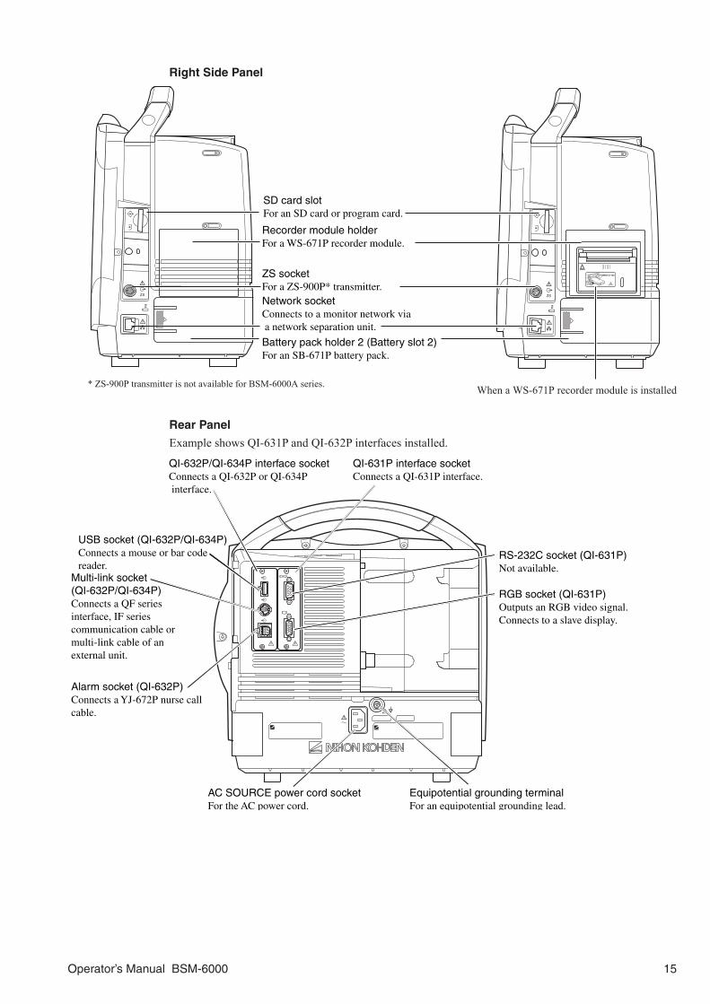
Right Side Panel
When a WS-671P recorder module is installed
Recorder module holder For a WS-671P recorder module.
SD card slot For an SD card or program card.
ZS socket For a ZS-900P* transmitter.Network socket Connects to a monitor network via a network separation unit.
Battery pack holder 2 (Battery slot 2) For an SB-671P battery pack.
* ZS-900P transmitter is not available for BSM-6000A series.
Rear Panel
Example shows QI-631P and QI-632P interfaces installed.
RGB socket (QI-631P)Outputs an RGB video signal.Connects to a slave display.
QI-631P interface socket Connects a QI-631P interface.
QI-632P/QI-634P interface socket Connects a QI-632P or QI-634P interface.
AC SOURCE power cord socket For the AC power cord.
Equipotential grounding terminal For an equipotential grounding lead.
USB socket (QI-632P/QI-634P) Connects a mouse or bar code reader.
Multi-link socket (QI-632P/QI-634P) Connects a QF seriesinterface, IF series communication cable ormulti-link cable of an external unit.
RS-232C socket (QI-631P) Not available.
Alarm socket (QI-632P) Connects a YJ-672P nurse callcable.

16 Operator’s Manual BSM-6000
MU-651R/MU-671R Main UnitFront Panel
AC power lamp Lights when the power cord is connected between the AC SOURCE socket and AC outlet.
Touch screen Displays monitoring data. Touching a key or data on the screen changes the displayed screen and settings.
Alarm indicator Red or yellow lamp blinks, or yellow or cyan lamps lights according to the alarm settings. Green lamp blinks in synchronization with the patient’s QRS or pulse.
Handle For carrying the monitor.
Silence Alarms key Silences the alarm sound.
NIBP Interval key Selects NIBP measurement mode. Pressing this key changes the mode.
NIBP Start/Stop key Starts NIBP measurement in the selected mode. Pressing the key during measurement stops measurement.
Menu key Displays the MENU window.
Home key Closes all opened windows and displays the home screen.
Power switch Press to turn the monitor power on. When turning the monitor power off, press and hold for more thanthree seconds.
Power lamp Lights when the monitor power is turned on.
Record/Stop key (option)Press to start or stop recording.
Remote control sensor Receives an infrared signal from the remote control.
Error lamp (option) Blinks when out of paper. Lights when the recorder door is open.
Speaker For alarm and sync sound.
Battery lamp 1Indicates a status of the battery in the battery slot 1.
Battery lamp 2 Indicates a status of the battery in the battery slot 2.
Left Side Panel
When an AY-673P input unit is installed
When an AY-673P input unit and AA-674P smart expansion unit are installed
AY-673P
AY-673PAA-674P
Battery pack holder For an SB-671P battery pack.
Input unit socket Connects an AY seriesinput unit or BSM-1700 series bedside monitor.

Operator’s Manual BSM-6000 17
Right Side Panel
When a WS-671P recorder module is installed
Recorder module holder For a WS-671P recorder module.
SD card slot For an SD card or program card.
ZS socket For a ZS-900P* transmitter.
Network socket Connects to a monitor networkvia the network separation unit.
* ZS-900P transmitter is not available for BSM-6000A series.
Rear Panel
RGB socketOutputs an RGB video signal.Connects to a dual display or slave display.
QI-671P interface socket Connects a QI-671P interface.
QI-672P interface socket Connects a QI-672P interface.
AC SOURCE power cord socket For the AC power cord. Equipotential grounding terminal
For an equipotential grounding lead.
USB sockets Connects a mouse or bar code reader.
Multi-link sockets Connects a QF seriesinterface, IF series communication cable or multi-link cable of an external unit.
RS-232C socket Not available.
Alarm socket Connects a YJ-672P nurse callcable.

18 Operator’s Manual BSM-6000
AY-631P/AY-633P/AY-651P/AY-653P/AY-660P/AY-661P/AY-663P/AY-671P/AY-673P Input Unit
Front Panel
AY-660P: One TEMP socket, one MULTI socket, no ECG/BP OUT socket
AY-631P/AY-651P/AY-661P/AY-671P: Two TEMP sockets, one MULTI socket
AY-633P/AY-653P/AY-663P/AY-673P: Two TEMP sockets, three MULTI sockets
Example is AY-673P input unit.
NIBP socket Connects to the air hose.
MULTI socket Connects to the connection cord of the parameter to be monitored (IBP, temperature, CO, CO
2, O
2,
respiration by thermistor method, SpO
2-2 (AY-661P/663P/671P/
673P only), BIS or CCO (APCO)). The type of parameter is automaticallyrecognized.
TEMP socket Connects to the temperature probe cord.
SpO2 socket Connects to the SpO
2 connection cord.
ECG/RESP socket Connects to the ECG connection cord.
ECG/BP OUT socket Outputs 100 mmHg/V IBP waveform and 1 mV/V ECG waveform and heart rate triggerby using the YJ-910P or YJ-920P ECG/BP output cable. These analog signals can be used as the synchronization signal for other equipment, such as IABP.
WARNINGWhen performing defibrillation during cardiac
output monitoring, never touch the CO connection
cord. The discharged energy may cause electrical
shock or injury.
CAUTIONWhen using the output signal from the monitor as
the synchronization signal for other equipment
such as an IABP (intra-aortic balloon pump) or
defibrillator:
• Set the timing of the IABP by checking the
waveform on the IABP screen.
• Check the condition of the bedside monitor at all
times. The output signal may become unstable.
• Check that the delay time of the output signal is
within the range of the connected equipment.
CAUTIONOnly a Nihon Kohden defibrillator can use the
output signal from the monitor as a
synchronization signal. Check that the delay time
of the output signal (heart rate trigger 20 ms
maximum) is within the range of the connected
defibrillator.

Operator’s Manual BSM-6000 19
NOTE:
• When using an IBP waveform as a synchronization signal for other equipment, connect
the IBP line to the MULTI socket on the input unit. The IBP waveform that is used for the
synchronization signal depends on the “IBP ANALOG OUT” setting in the SYSTEM SETUP
window.
- When “IBP ANALOG OUT” is set to FIXED POSITION:
The IBP line connected to the top MULTI socket on the input unit is used.
- When “IBP ANALOG OUT” is set to HIGHEST PRIORITY LABEL:
When more than one IBP waveform is acquired, the IBP waveform of the highest priority
label is used.
IBP label priority:
ART > ART2 > RAD > DORS > AO > FEM > UA > LVP > P1 > P2 > P3 > P4 > P5 > P6 > P7
• Analog ECG, analog BP and heart rate trigger output are not available when an AY-660P input
unit is used.
• The output signal from the ECG/BP OUT socket may become unstable in the following
conditions.
- Electrode is dry or detached.
- Electrode lead is damaged or disconnected from the electrode.
- Electrode lead is pulled.
- AC interference or EMG noise superimposed.
- Air bubbles or blood clog in the circuit for monitoring IBP.
- Cord or cable is disconnected or damaged.
• All instruments which are to be connected to the ECG/BP OUTPUT socket must use a
YJ-910P or YJ-920P ECG/BP output cable and comply with the IEC 60601-1 safety standard
for medical equipment.
Left Side PanelWhen the side panel is removed
Side panel Remove to attach an AA-672P or AA-674P smart expansion unit.
Smart expansion unit socket Connects an AA-672P or AA-674P smart expansion unit.
20 Operator’s Manual BSM-6000
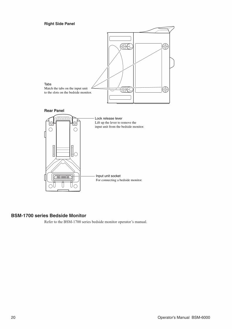
Right Side Panel
Tabs Match the tabs on the input unit to the slots on the bedside monitor.
Rear Panel
Input unit socket For connecting a bedside monitor.
Lock release lever Lift up the lever to remove the input unit from the bedside monitor.
BSM-1700 series Bedside MonitorRefer to the BSM-1700 series bedside monitor operator’s manual.

Operator’s Manual BSM-6000 21
AA-672P/AA-674P Smart Expansion UnitFront Panel
AA-672P AA-674P
MULTI socket Connects to the connection cord of the parameter to be monitored (IBP, temperature, CO, CO
2, O
2,
respiration by thermistor method, SpO
2-2 (AY-661P/663P/671P/
673P only), BIS or CCO (APCO)). The type of parameter is automatically recognized.
Right Side Panel
Connector Connects an AY-631P, AY-633P, AY-651P, AY-653P, AY-661P, AY-663P, AY-671P or AY-673P input unit.

22 Operator’s Manual BSM-6000
Installation
GeneralThe monitor must be installed by qualified personnel. Details are in the Administrator’s Guide.
WARNINGOnly use the provided power cord. Using other
power cords may result in electrical shock or injury
to the patient and operator.
WARNINGWhen several medical instruments are used
together, ground all instruments to the same
one-point ground. Any potential difference between
instruments may cause electrical shock to the
patient and operator.
WARNINGConnect only the specified instrument to the
monitor and follow the specified procedure. Failure
to follow this warning may result in electrical shock
or injury to the patient and operator, and cause fire
or instrument malfunction.
WARNING• Do not install the monitor and optional units
above the patient.
• Only use the specified tools or equipment when
installing the monitor and units. Failure to follow
this warning may result in the monitor or unit
falling and injuring the patient.
CAUTIONOnly use the specified stand, cart or equipment for
installing the monitor and instruments. Using
non-specified equipment may result in the
instruments falling and causing injury.
CAUTIONWhen not using the specified cart, carefully set the
monitor to prevent it from falling off or tipping over.
CAUTIONBefore connecting or disconnecting instruments,
make sure that each instrument is turned off and
the power cord is disconnected from the AC
socket. Otherwise, the patient or operator may
receive electrical shock or injury.
Make sure that there is more than 5 cm of space between the monitor and the wall for adequate ventilation. When the monitor is surrounded, make sure that there is about 10 cm of space above the monitor for ventilation so that the operating temperature does not exceed 40°C (104°F).
10 cm
5 cm Rear Panel
5 cm
Side Panel

Operator’s Manual BSM-6000 23
Grounding the Monitor
When more than one electrical instrument is used, there may be electrical potential difference between the instruments. The potential difference between the instruments may cause current to flow to the patient connected to the instruments, resulting in electrical shock.
When equipotential grounding is required, connect the equipotential ground terminal on the instrument to the equipotential ground terminal on the wall (equipotential grounding system) with the equipotential grounding lead (potential equalization conductor).
NOTE:
• For details on connecting an external instrument to the monitor, contact your Nihon Kohden
representative.
• Leakage current may increase when interconnecting many medical instruments to the monitor.
Environment for External Instruments
Use external instruments in the following environment.
Medically-used room
Patient Environment Outside the Patient EnvironmentNon-medically used room
Sub display(IEC 60601-1 complied or
using the isolation transformercomplied to IEC 60601-1)
Sub display(IEC 60601-1 complied or
using the isolation transformercomplied to IEC 60601-1)
Externalinstruments
(IEC 60601-1 complied)
Central monitorNetwork printer(IEC xxx complied)
Remote controllerRY-910PA
InterfaceQF series
Communication cable
IF series
External instruments
(IEC 60601-1 complied)
MouseBar code reader
Smart expansion unitAA-672P/674P
Hyper isolation transformer
HIT-100
Input unitAY-631P/633PAY-651P/653P
AY-661P*/663P*AY-671P/673P
Recorder moduleWS-671P
TransmitterZS-900P
Wireless LANstation
QI-320PA/420PA
BSM-6301/6501/6701
InterfaceQI-632P/634P(For MU-631R)
QI-672P(For MU-651R/671R)
InterfaceQI-631P
(For MU-631R)
InterfaceQI-671P
(For MU-651R/671R)
Main unitMU-631R/671R/651R
Input unitAY-660P*
Multigas unitGF-110PA/210R*
Multigas/Flow unitGF-120PA*/220R*
Neuro unitAE-918P
* These units are not available for BSM-6000A series.
Bedside monitorBSM-1700 series
InterfaceQI-670P*

24 Operator’s Manual BSM-6000
Warnings and Cautions for Connecting the Monitor to a Network
WARNINGInstall all network devices, including printer and
hubs, outside the patient environment (IEC 60601-
1-1). If they are installed inside the patient
environment, the patient or operator may receive
electrical shock or injury. For installation, contact
your Nihon Kohden representative.
WARNINGCheck the software version number of the monitor
before connecting it to the network. Different
software versions have different communication
methods. More than one communication method in
a network may cause communication failure. For
details, refer to the Network and System
Installation Guide.
WARNINGConnect the monitor to network as specified.
Otherwise the patient and operator may receive
electrical shock or injury. To connect the network,
contact your Nihon Kohden representative.
WARNINGDo not use a damaged network cable. The patient
or operator may receive electrical shock when the
damaged part is touched.
WARNINGIn a network where this monitor is connected,
connect only the specified instruments.
Unspecified instruments may cause electrical
shock or injury to the patient and operator or
cause instrument malfunction, instrument stop, or
data loss.
CAUTIONWhen the monitor is connected to a central
monitor network, set the Bed Name (Bed ID) and
Group Name on the monitor. Otherwise, the default
settings are used for the bed name and group
name and the bed may be incorrectly identified on
the central monitor.
CAUTIONThe network must be managed by the network
administrator. Make sure that each monitor in the
network has a different IP address. Otherwise,
data communication cannot be performed properly.
When adding a monitor to an already operating
network, set the IP address on the monitor before
connecting the monitor to the network.

Operator’s Manual BSM-6000 25
Inserting and Removing the Battery PacksThis monitor can hold two battery packs. Insert the battery pack to the battery slot 1 or/and battery slot 2.
NOTE:
• Only use the SB-671P battery pack.
• The procedure for inserting and removing the battery packs is the same for
BSM-6301 and BSM-6501/BSM-6701 bedside monitors even though the
battery slot positions and battery cover shapes are different.
Inserting the Battery Pack
1. Remove the battery cover by pressing the tab on the battery cover and slide the cover off.
2. Insert the battery pack with the label (black) facing up in the battery slot.
3. Attach the battery cover.
Battery slot 1
Battery slot 2
Battery cover
Battery packBattery lever

26 Operator’s Manual BSM-6000
Removing the Battery Pack
1. Remove the battery cover by pressing the tab on the battery cover and slide the cover off.
2. Press the battery lever to release the lock.
3. Pull out the battery pack from the battery slot.
4. Attach the battery cover.
Battery cover
Battery lever

Operator’s Manual BSM-6000 27
Inserting and Removing the AY-600P series Input Unit or BSM-1700 series Bedside Monitor
The AY-600P series input unit or BSM-1700 series bedside monitor can be inserted to or removed from the monitor. When the patient is changed or moved to a different location, insert or remove the input unit or BSM-1700 series bedside monitor.
The following procedure is for the AY-600P series input unit. For details on inserting and removing the BSM-1700 series bedside monitor, refer to the BSM-1700 series bedside monitor operator’s manual.
Inserting the Input Unit
1. Put the input unit into the rear of the monitor so that the four tabs go into the four slots.
2. Slide the input unit all the way into the monitor until it clicks into place.
Removing the Input Unit
CAUTIONWhen inserting or removing the input unit from the monitor, be careful
not to drop it.
Slide out the input unit while pulling up the lock release lever.
Slots
Tabs
Input unit socket
Connector
Lock release lever

28 Operator’s Manual BSM-6000
Loading Recording PaperWhen using the WS-671P recorder module, load recording paper as follows.
CAUTIONDo not touch the thermal head inside the recorder module. The thermal head may be
damaged by static electricity or become dirty and cause printing failure.
1. Move the door release lever in the direction of the arrow ( ) to release the lock.
2. Open the recorder door. Set the recording paper (FQW50-2-100) inside the recorder module so that the detection mark (small black square on corner) of the paper is on the right side.
3. Draw out one page of paper toward you and close the recorder door.
If the out of paper lamp is still lit, the recorder door is not closed properly.
Door release lever
Mark

Operator’s Manual BSM-6000 29
Turning the Monitor On or Off
Turning the Monitor OnThe monitor can operate on either battery or AC power. When the monitor is installed and the power cord is connected, the AC power lamp lights. When a battery pack is installed and the power cord is disconnected or there is a sudden power failure, the monitor automatically switches to battery power. The monitor can operate for about 90 minutes (BSM-6301/BSM-6501) or 60 minutes (BSM-6701) with a new fully charged battery pack when:• Used in normal temperature.• Recorder is stopped.• No alarm occurs.• Monitoring ECG, respiration (impedance) and SpO2.• <POWER SAVING MODE> on the SYSTEM SETUP window is set to ON.• <SYNC SOUND VOLUME> on the VOLUME window is set to OFF.• NIBP measurement interval is 15 minutes.• QI-671P and QI-672P interfaces or QI-631P and QI-632P or QI-634P interfaces are installed in the
monitor.• The input unit is an AY-600P series input unit and not a BSM-1700 series bedside monitor.
Check Before Turning On the Power
Check the following items before turning on the power.• Enough electrodes and electrode leads are ready.• Cleaned and sterilized sensors and transducers are ready.• Power cord is connected properly.• Equipotential grounding lead is connected properly when equipotential grounding is required.• All cables are connected properly.• Enough recording paper in the recorder (when using an optional recorder).• Fully charged battery pack is installed in the monitor in case of a sudden power failure.• No scratches, damage or dirt on the monitor.• No damage to the keys and panels.• No damage to the power cord.• No damage to the electrode leads, transducers, probes and cables.• The monitor is not in a wet place.
NOTE: When the AC power lamp is not lit, check the power cord connection.
The AC power lamp does not light when there is not enough current to each
unit.
When the power cord is connected between the bedside monitor and AC outlet and the AC power lamp lights, press the [Power] switch on the front panel to turn the power on. The power lamp and the AC power lamp light and self check starts. When the check is complete, the home screen appears.
NOTE: Even though the position of symbol marks for the lamps are different on
BSM-6301 and BSM-6501/BSM-6701 bedside monitors, the function and the
position of lamps are the same.
Lit Lit

30 Operator’s Manual BSM-6000
The power can also be turned on by pressing the [POWER] button on the remote control.
CAUTIONWhen the monitor is turned on, check that a single beep sounds and the red, yellow, cyan
and green alarm indicator lamps blink once. This shows that the alarm is functioning
properly.
NOTE: The sound volume when the monitor power is turned on is the volume set on <ALARM
VOLUME> of the VOLUME window.
When the monitor power is turned on, alarms are suspended while the monitor is waiting for the electrodes and probe to be attached to the patient. The monitoring starts when the connection cord is connected to the socket on the monitor and the electrodes or probe are attached to the patient. The alarm activates when one of the following occurs:• ECG, SpO2 or IBP is monitored or NIBP is measured and a value is displayed (when AUTO is selected
for <ALARM ACTIVATION DELAY> on the ALARM window of the SYSTEM SETUP window).• ECG, SpO2 or IBP is continuously monitored for the selected time (when 1 min, 2 min or 3 min is
selected for <ALARM ACTIVATION DELAY>).• NIBP is measured (when 1 min, 2 min or 3 min is selected for <ALARM ACTIVATION DELAY>).
Check After Turning On the Power and During Monitoring
To start monitoring safely and properly, check the following items after turning on the power. If any problem is detected, take the proper countermeasure according to the troubleshooting and maintenance sections.
• There is no fire, smoke or smell.• The monitor is not too hot.• The power lamp and other lamps light.• Alarm indicators (red, yellow, cyan and green lamps) blink once and a beep sounds.• The start up screen and the home screen appears.• No error message is displayed on the screen.• The time on the screen is correct.• The monitor does not affect surrounding equipment.• The data and waveforms are displayed properly.• Keys and switches operate properly.• The touch keys function properly and the key clicking sound is generated.• Alarm functions properly.• Alarm sound can be heard.• Alarm sound volume setting is appropriate.• There is no trouble in recording (when using an optional recorder).• Sound can be heard from the monitor.

Operator’s Manual BSM-6000 31
Power and Battery Status Indications
Battery slot No.
Battery slot 1
Battery slot 2
Battery slot 1 Battery slot 2
BSM-6301 BSM-6501/BSM-6701
Remaining battery power
more than 90%more than 60%more than 40%more than 25%less than 25%
Battery operation
Operating on battery
Battery is being charged
Power and battery status are indicated by four lamps on the bedside monitor. A discharged battery is also indicated by battery marks, screen message and alarm.
NOTE:
• When charging the battery pack with the monitor power turned off, check that the power
lamp and battery charging lamp light. If the lamps do not light even when the power cord is
connected and the battery pack is inserted, turn the power on, check that the battery charging
lamp is blinking or lit, then turn the power off.
• Even though the position of symbol marks for the lamps are different on BSM-6301 and
BSM-6501/BSM-6701 bedside monitors, the function and the position of lamps are the same.
• Operating on AC power and battery pack is fully charged or there is no battery Power lamp: Lit AC power lamp: Lit Battery lamp 1: Lit or off Battery lamp 2: Lit or off
• Operating on AC power and battery pack is being charged Power lamp: Lit AC power lamp: Lit Battery lamp 1: Slow blinking (once every 2 seconds) or off Battery lamp 2: Slow blinking (once every 2 seconds) or off
• Operating on AC power when battery pack is damaged Power lamp: Lit AC power lamp: Lit Battery lamp 1: Rapid blinking (4 times per second) or off Battery lamp 2: Rapid blinking (4 times per second) or off Screen indication: “BATTERY ERROR” message Alarm indication: Continuous “bing bong” sound (when NK1 is selected for
<ALARM SOUND TYPE> on the ALARM window of the SYSTEM SETUP window) and blinking yellow alarm indicator lamp

32 Operator’s Manual BSM-6000
• Operating on battery power Power lamp: Lit AC power lamp: Off Battery lamp 1: Lit* or off Battery lamp 2: Lit* or off
* When two battery packs are used and when the battery pack which is not used is fully charged
• Operating on battery power and battery pack is damaged Power lamp: Lit AC power lamp: Off Battery lamp 1: Rapid blinking (4 times per second) or off Battery lamp 2: Rapid blinking (4 times per second) or off Screen indication: “BATTERY ERROR” message Alarm indication: Continuous “bing bong” sound (when NK1 is selected for
<ALARM SOUND TYPE> on the ALARM window of the SYSTEM SETUP window) and blinking yellow alarm indicator lamp
• No monitoring and charging battery pack Power lamp: Off AC power lamp: Lit Battery lamp 1: Slow blinking (once every 2 seconds) or off Battery lamp 2: Slow blinking (once every 2 seconds) or off
Battery Pack Handling and Operation
WARNINGDo not do the following to the battery pack. It may
cause leakage, overheating, explosion and fire.
• Short-circuit the + and – terminals on the battery
pack.
• Put the battery pack into fire or heat the battery
pack.
• Disassemble or modify the battery pack.
• Give strong impact to or deform the battery pack.
• Use the battery pack on unspecified instruments.
• Charge the battery pack on unspecified
instruments.
• Install the battery pack with the wrong polarity.
• Leave the battery pack in the reach of patients.
WARNINGIf the battery pack is damaged and the substance
inside the battery pack contacts the eyes or skin,
wash immediately and thoroughly with water and
see a physician. Never rub your eyes, because you
may lose your eyesight.
WARNING• Do not immerse the battery pack in water. The
battery pack may heat up and rust and the
substance inside the battery pack may leak.
• Do not leave the battery pack unused for more
than about two years. The battery pack may leak.
CAUTIONDo not expose the battery pack to direct sunlight
or leave in a high temperature place. The lifetime
of the battery pack may be shortened, the
performance of the battery pack may be degraded
and the battery pack may leak.
CAUTIONDo not use a battery pack with a damaged cover.
The operator may receive electrical shock.

Operator’s Manual BSM-6000 33
CAUTIONDo not tilt the monitor when removing the battery
pack from the monitor. If the lock release lever is
lifted while the monitor is tilted, the battery pack
falls out of the monitor and may injure the patient
or operator.
CAUTIONDo not leave the battery pack near the patient or in
reach of children.
CAUTIONDo not use a battery pack which is past the
expiration date written on the label.
CAUTIONDo not subject the battery pack to a strong
mechanical shock.
CAUTIONUse the battery pack between 10°C (50°F) and
40°C (104°F). Temperatures out of this range affect
the working of the battery.
CAUTIONBefore disposing of the battery pack, check with
your local solid waste officials for details in your
area for recycling options or proper disposal. The
battery pack is recyclable. At the end of its useful
life, under various state and local laws, it may be
illegal to dispose of this battery pack into the
municipal waste stream.
NOTE: Be careful when handling the fully charged battery pack. The battery pack heats up to
about 60°C (140°F).
Battery Pack Handling Procedures• Always place a battery pack in the monitor. This charges it so that you will always have a fully charged
battery pack ready.• Fully recharge the battery pack before using it for the first time or after storing it for over a month.
When the battery pack is not used, it self-discharges.• Replace the battery pack with a new one every year. This is because the battery pack is a chemical
product which gradually deteriorates whether or not it is used.• Store the battery packs under the following conditions. Temperature: –20 to +60°C (–4 to +140°F) (within 30 days) –20 to +45°C (–4 to +113°F) (within 90 days) –20 to +35°C (–4 to +95°F) (more than 90 days) Humidity: 20 to 85% RH (noncondensing)
When Not Using the Monitor or Battery Pack• When the monitor is not used for a long time, remove the battery pack. When a charged or discharged
battery pack is left inside the monitor with the power cord unplugged, the battery pack self-discharges and deteriorates.
• When a battery pack is not used, fully charge it before storage. When a battery pack is not used for over one month, fully charge it once every six months.
When the “BATTERY WEAK” Message AppearsOperate the monitor on AC power and/or replace the battery pack when the “BATTERY WEAK” message appears. When the “BATTERY WEAK” message appears, the remaining battery power is less than 25%. The yellow alarm lamp lights with a continuous “bing bong” sound.

34 Operator’s Manual BSM-6000
If no AC or battery power is supplied to the monitor, there is no measurement and patient data such as trend data may be lost.
Charging the Battery Pack
The battery pack can be charged by the monitor. It takes about 10 hours to charge one battery pack during monitoring and 6 hours to charge two battery packs when not monitoring.
NOTE: The new battery pack is not charged. Charge the battery pack before use.
The monitor can operate for about 90 minutes (BSM-6301/BSM-6501) or 60 minutes (BSM-6701) with a new fully charged battery pack when:• Used in normal temperature.• Recorder is stopped.• No alarm occurs.• Monitoring ECG, respiration (impedance) and SpO2.• <POWER SAVING MODE> on the SYSTEM SETUP window is set to ON.• <SYNC SOUND VOLUME> on the VOLUME window is set to OFF.• NIBP measurement interval is 15 minutes.• QI-671P and QI-672P interfaces or QI-631P and QI-632P or QI-634P interfaces are installed in the
monitor.• The input unit is an AY-600P series input unit and not a BSM-1700 series bedside monitor.
CAUTIONWhen charging the battery pack, keep the ambient temperature at approximately 20°C to
maintain the optimal battery operation time. If the battery pack is charged at less than 10°C
(50°F) or more than 30°C (86°F), the maximum battery operation time will be 20% to 30%
less than the optimal operation time.
Charging in the MonitorNormal charging
During AC operation, the battery pack is automatically charged without interrupting monitoring. It takes approximately 10 hours of continuous charging to fully charge a battery pack.
Fast charging
It takes 6 hours of continuous charging to fully charge two battery packs when not monitoring. When installing two battery packs, the monitor can charge the two battery packs at the same time.
After continuous charging, the monitor automatically switches to trickle charging mode to keep the battery pack fully charged. Trickle charging is necessary because the battery pack can self-discharge even when it is not in use.
NOTE: Do not disconnect the power cord from the monitor during battery charging.
Stored Data Status at Power OnStored data status at power on depends on the settings on the DATA MANAGEMENT window of the SYSTEM CONFIGURATION screen, whether the previous patient is discharged, and whether the power is off for more than 30 minutes. For details, refer to the “Admitting/Discharging Patient” section.

Operator’s Manual BSM-6000 35
Monitor Status on Power InterruptionWhen there is a power failure or sudden power interruption, the monitor status is as follows.• When a battery pack is installed in the monitor, the BSM-6301 and BSM-6501 operate for about 90
minutes and the BSM-6701 operates for about 60 minutes on battery power.• When the monitor has no battery pack installed or the battery pack is discharged, the monitor turns off.
When the AC power is restored, the monitor turns on automatically. The patient data and settings are stored for about 30 minutes after power off when <DATA TRANSPORT USING INPUT UNIT> is set to DISABLE and <SHOW ADMIT CONFIRMATION WINDOW> is turned off in the SYSTEM CONFIGURATION screen.
When <DATA TRANSPORT USING INPUT UNIT> is set to ENABLE, the patient data and settings are always stored.
When there is a power failure or sudden power interruption, immediately connect the monitor to the emergency power source. It is recommended to always keep the battery pack in the monitor.
Turning the Monitor OffPress the [Power] switch on the bedside monitor for more than three seconds to turn the power off. The screen becomes dark and the power lamp on the front panel turns off.
NOTE:
• Press the [Power] switch and hold for more than three seconds to turn the
power off.
• Do not disconnect the power cord while the monitor power is on. Data may
be lost.
• Even though the position of symbol marks for the lamps are different on
BSM-6301 and BSM-6501/BSM-6701 bedside monitors, the function and the
position of lamps are the same.
The power can also be turned off by pressing the [POWER] button for more than three seconds on the remote control.
Check After or Before Turning the Power Off
Check the following items for the next use.• Previous patient data is deleted.• Temporarily changed settings are changed back to the previous settings.• There is no dirt, damage or scratches on the monitor.• The sensors, probes, transducers, and cables are cleaned and sterilized.• Accessories are cleaned and stored properly.• There are enough consumables, such as recording paper, and disposable electrodes for the next use.• Battery pack is fully charged.• The power switch on the monitor is turned off and the power cord is disconnected from the monitor.• The monitor is not in a wet place.• Dead batteries are disposed of properly.• The medical waste is disposed of properly.• The monitor is stored properly.
LitOff

36 Operator’s Manual BSM-6000
Basic Operation
The monitor can be operated by the following methods. These methods can be used together.• The hard keys on the bedside monitor• Touch screen• Remote control• Mouse
This manual mainly describes operations using the hard keys on the bedside monitor and touch screen.
Using the Hard Keys on the Bedside Monitor and Touch ScreenPress the key on the bedside monitor to open the window or operate the function assigned to the key.
Press the key on the screen to select the setting or open/close a window. You can use the scroll bar on the screen to scroll data on the window.
There is a pip sound when a key or screen is touched, or the scroll bar on the screen is used.
Using the Remote ControlUse the remote control to operate the monitor from a distance. A pointer appears on the screen when the monitor is operated by the remote control. The remote control channel can be assigned to the monitor to prevent operating a different monitor. Point the transmitter on the remote control to the remote control sensor on the bedside monitor.
Press the keys on the remote control to open/close a window.Move the selection knob up/down/left/right to scroll the data or select a setting and press the [ENTER] key to register the setting.
There is a pip sound when a key on the remote control is pressed or the selection knob is moved to scroll the data.
NOTE:
• Watch the monitor screen and check the operation when using the remote control to avoid
wrong operation.
• Make sure that the remote control is handled appropriately.
Using the MouseWhen connecting a QI-632P, QI-634P or QI-672P interface, use the mouse to move the pointer on the screen and click the left button to select and register the setting.
There is a pip sound when the mouse is clicked.
1

Operator’s Manual BSM-6000 37
Home Screen Description
The home screen displays the numeric values and waveforms of the monitoring parameters, current trendgraphs, various messages and operation keys. Different screen layouts are available by changing the settings on the SYSTEM SETUP window.
ECG
Heart rate
ECG lead
Current date and time
ECG sensitivity
VPC
Patient name
ST level
Bed ID
Function keys
Current trendgraphsThe width of the trendgraph can be changed. OCRG can be displayed instead of trendgraphs.
Numeric values
Waveforms
Respiration rateRespiration rate is detected from one parameter. When several respiration parameters are monitored at the same time, the respiration rate is counted from the parameter in the following priority.Anesthetic gas > Flow > CO2 > thermistor respiration > impedance respiration
The respiration rate is detected from two parameters when <DISPLAY IMP-RR AS SECOND PARAMETER> is set to ON.
Alarm limit settingsFor BSM-6000A series, when the limit is set to OFF, “OFF” is displayed. For BSM-6000K series, when the limit is set to OFF, “---” is displayed.
ECG filter mode
QRS detection type
Initial cuff inflation pressure type
Patient type
To close the opened window and return to the home screen, press the [Home] key on the bedside monitor or the [MENU/HOME] key on the remote control.
Touching the following items on the home screen displays the following windows.• Numeric value: Parameter window• Patient name: ADMIT DISCHARGE window• Time: DATE window• Function key: Window assigned to the function key
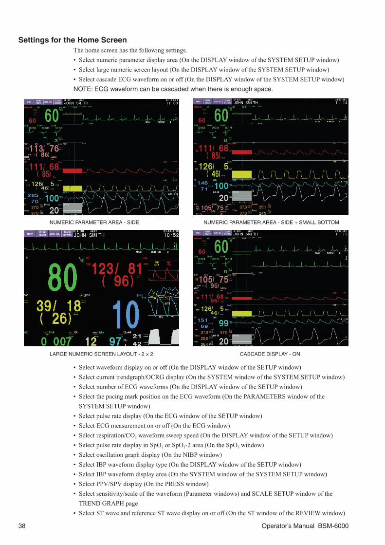
38 Operator’s Manual BSM-6000
Settings for the Home ScreenThe home screen has the following settings.• Select numeric parameter display area (On the DISPLAY window of the SYSTEM SETUP window)• Select large numeric screen layout (On the DISPLAY window of the SYSTEM SETUP window)• Select cascade ECG waveform on or off (On the DISPLAY window of the SYSTEM SETUP window)NOTE: ECG waveform can be cascaded when there is enough space.
NUMERIC PARAMETER AREA - SIDE NUMERIC PARAMETER AREA - SIDE + SMALL BOTTOM
LARGE NUMERIC SCREEN LAYOUT - 2 × 2 CASCADE DISPLAY - ON
• Select waveform display on or off (On the DISPLAY window of the SETUP window)• Select current trendgraph/OCRG display (On the SYSTEM window of the SYSTEM SETUP window)• Select number of ECG waveforms (On the DISPLAY window of the SETUP window)• Select the pacing mark position on the ECG waveform (On the PARAMETERS window of the
SYSTEM SETUP window)• Select pulse rate display (On the ECG window of the SETUP window)• Select ECG measurement on or off (On the ECG window)• Select respiration/CO2 waveform sweep speed (On the DISPLAY window of the SETUP window)• Select pulse rate display in SpO2 or SpO2-2 area (On the SpO2 window)• Select oscillation graph display (On the NIBP window)• Select IBP waveform display type (On the DISPLAY window of the SETUP window)• Select IBP waveform display area (On the SYSTEM window of the SYSTEM SETUP window)• Select PPV/SPV display (On the PRESS window)• Select sensitivity/scale of the waveform (Parameter windows) and SCALE SETUP window of the
TREND GRAPH page• Select ST wave and reference ST wave display on or off (On the ST window of the REVIEW window)

Operator’s Manual BSM-6000 39
Trendgraph on the Home Screen (Current Trendgraph)The latest 30 minute parameter data can be displayed as a trendgraph on the home screen. This trendgraph can be dragged left or right by touching the right edge of the trendgraph on the screen.
OCRG
The OCRG (oxygen-cardio-respirogram) can be displayed on the home screen instead of a trendgraph. To display OCRG on the home screen, select either “OCRG 1 cm/min” or “OCRG 3 cm/min” for <CURRENT TREND> on the DISPLAY window of the SYSTEM SETUP window.
Freezing WaveformsYou can freeze (stop sweeping) the waveforms on the home screen by touching the FREEZE function key at the upper left corner of the screen or on the remote control. The waveforms are frozen for 3 minutes or until the interbed window appears. To unfreeze the waveforms manually, touch any key on the screen or press any key on the bedside monitor.
Using the TimerThe timer can be displayed on the home screen by touching the TIMER key on the MENU window or the TIMER function key on the upper left of the screen if the TIMER is assigned to the function key. To start counting up, touch the START key on the TIMER window. To stop the timer, touch the STOP key. When closing the TIMER window, touch the RESET key to reset the timer and touch the key.
Car Seat ChallengeThe American Academy of Pediatrics recommends car seat challenge for all neonates born before 37 weeks gestation to ensure that the neonate is able to sit in a car seat safely without any episodes of oxygen desaturation apnea or bradycardia.
The CAR SEAT CHALLENGE window measures a neonate’s lower heart rate limit, lower SpO2 limit and apnea time for a set duration. This function is only available on BSM-6000A series bedside monitors when the site mode is NICU.

40 Operator’s Manual BSM-6000
Using Sleep ModeTo prevent the monitor from disturbing the patient during sleep or other times, use the SLEEP MODE. In sleep mode, the screen is darkened and sync sound is turned off. To turn sleep mode on, touch the SLEEP key on the MENU window. The sleep mode is only available when the ZS-900P* transmitter is connected or the bedside monitor is connected to the central monitor network.* ZS-900P transmitter is not available for BSM-6000A series.
WARNINGWhen using sleep function, monitor the patient on the central monitor or telemetry system. Otherwise, the bedside monitor alarm may be overlooked. When <EXIT SLEEP MODE ON CRISIS ALARM> check box on the ALARM page of the SYSTEM SETUP window is OFF, bedside monitor alarms and sync sound appear on the central monitor but do not appear on the bedside monitor during sleep mode.
To turn the sleep mode off, touch the screen or press any hard key on the bedside monitor. When the sleep mode is turned off by pressing a hard key, the function of that hard key is also performed.
When <EXIT SLEEP MODE ON CRISIS ALARM> on the SLEEP page of the SYSTEM SETUP window is set to ON, the sleep mode is turned off when an CRISIS level alarm occurs. When the time is set in <SLEEP MODE WILL END AT> box, the monitor exits the sleep mode on the set clock time.
When the communication between the bedside monitor and central monitor is interrupted, the bedside monitor exits sleep mode.

Operator’s Manual BSM-6000 41
MENU Window Description
Press the [Menu] key on the bedside monitor or the [MENU/HOME] key on the remote control to display the MENU window. Any window, except for the home screen and SYSTEM CONFIGURATION screen, can be displayed from the MENU window. The MENU window layout differs according to the selected site.
Example: OR or ICU site
Opens the basic parameter window for changing parameter-related settings.Opens the review window.
Changes alarm settings.
Opens the window for changing date and time, sync/alarm sound volume, screen brightness, waves, recording and assigning functions to remote control keys and administrator setting window.
Enters patient information and deletes data.
Opens the 12 lead analysis/calculation window, displays the drug, lung function, interbed, and timer windows, touch key function on/off, and displays the large numeric screen.
Turns sleep mode on (in ICU and NICU mode only).
Suspends all alarms indefinitely in ICU/NICU mode (“BYPASS” in OR mode).
Suspends all alarms for the set time (1, 2 or 3 minutes).
Opens the parameter window for changing parameter-related settings.
NOTE:
• On BSM-6000A series,
- FLOW/Paw key is not available.
- 12 LEAD and 12 LEAD ANALYSIS keys are not available when the site setting is NICU and
12 LEAD ANALYSIS is set to Off in the SYSTEM CONFIGURATION screen.
- When the site setting is NICU, the CAR SEAT CHALLENGE key is in the <OTHER> box.
• On BSM-6301A/K, aEEG is not available.
• aEEG is only available when EEG is monitored with AE-918P neuro unit with software version
02-01 or later.
• When the site setting is NICU, the OCRG key is in the <REVIEW> box.
For the alarm off key on the MENU window, refer to “Silencing/Suspending Alarms” in this manual.

42 Operator’s Manual BSM-6000
Changing Settings
Administrator SettingsSome settings can only be changed by the administrator. A password is required to display the window or enter the screen for changing these settings. These settings are:• Settings on the SYSTEM SETUP window• Settings on the SYSTEM CONFIGURATION screen
The details for these settings are described in the Administrator’s Guide.
WARNINGST, CO2, RESPIRATION, tcPO2/tcPCO2 and HEMOGLOBIN settings only affect the
individual bedside monitor, not on all monitors connected to the network. The unit settings
must be the same on all bedside monitors and central monitors in the network. Otherwise,
the different measurement values and alarms will be displayed on different monitors
depending on the unit settings on each monitor.
CAUTIONWhen installing the monitor, change the time zone setting to the same setting as the other
bedside monitors and central monitors. If the time zone setting is not the same, the data
which was in the input unit before transport is deleted when using the transport function
with the input unit.
Changing Parameter Settings and Other Settings• DATE window for setting date and time• VOLUME window for setting alarm and sync sound volume• DISPLAY window for setting number of ECG waveforms, waveform display, IBP waveform display
type and waveform sweep speed on the home screen• RECORD window for setting recording parameters• SYSTEM window for checking assigned functions to the remote control keys• Parameter windows for setting various parameter-related settings
Changing Settings
1. Display the MENU window.
2. Touch the desired menu key on the MENU window to display the setting window.
3. Change the desired item by touching the keys or buttons, or dragging the slider displayed on the setting window.

Operator’s Manual BSM-6000 43
Example: To correct the date and time1. Display the DATE window of the SETUP window. Press the [Menu] key → DATE key.
Or, Touch the date and time at the upper right corner on the home
screen.
2. Touch the item key to be changed on the DATE window.
3. Touch the desired number key(s).
4. Repeat steps 2 and 3 to change other items.
5. Touch the SET key to enter the setting.
Example: Change the ECG lead1. Display the MAIN page of the ECG window. Press the [Menu] key → ECG key → MAIN tab.
Or, Touch the heart rate value on the home screen.
2. Touch the desired lead key from <LEAD> box.
To change the lead for the second and third traces on the home screen, display the ECG2/3 WAVES page of the ECG window and select the lead for each trace.
Changing Settings on the VOLUME Window
<SYNC SOUND VOLUME>: Set the volume for the sync sound.When ON is selected, there is a beeping sound.
<ALARM VOLUME>: Set the volume for the alarm sound. The alarm volume cannot be turned off.
NOTE: Set the alarm volume depending on the monitoring
environment. When you drag the slider or touch the key
to the lowest level, the alarm sound goes to the minimum
volume.

44 Operator’s Manual BSM-6000
Admitting/Discharging Patient
WARNINGCheck the alarm settings when admitting a new patient and whenever the patient condition
changes and change the alarm settings if necessary. The alarm settings return to the alarm
master settings on the SYSTEM SETUP window when:
• A patient is admitted or discharged.
• <SHOW ADMIT CONFIRMATION WINDOW> is set to “Off” in the SYSTEM
CONFIGURATION screen and 30 minutes elapse after monitor power off.
• “PATIENT TYPE” is changed on the ADMIT DISCHARGE window.
CAUTIONWhen admitting a new patient, first delete all data of the previous patient. Otherwise, the
data of the previous patient and new patient will be mixed together.
When the patient is admitted or discharged, the alarm settings, arrhythmia analysis on/off and QRS detection type setting return to the alarm master settings, the NIBP measurement mode returns to the INTERVAL MASTER settings on the SYSTEM SETUP window and the following data are deleted.
• Patient information (only when the patient is discharged) • Current trendgraph on the home screen• Data on the review windows • Data on the 12 LEAD ANALYSIS window• Data on the DRUG window • Data on the LUNG FUNCTION window• PCWP value on the CO window • Thermodilution curve on the CO window• CO table on the MEASURE page of the CO window • CSA/DSA graph
When the patient is discharged, the PATIENT TYPE setting returns to the alarm master settings.
Admitting a PatientEnter the patient information to admit the patient. Before entering data for a new patient, you must first discharge a previous patient. Refer to the “Discharging a Patient” section.
1. Display the ADMIT page of the ADMIT DISCHARGE window by doing any of the following. • Press the [Menu] key → ADMIT DISCHARGE key.• Touch the patient name area at the upper part of the
home screen.
• When <ADMIT MODE> is set to MANUAL, the STANDBY window appears after discharging a patient. Touch the ADMIT key on the STANDBY window.

Operator’s Manual BSM-6000 45
The STANDBY window depends on the <STANDBY MODE> setting in the SYSTEM CONFIGURATION screen. When <STANDBY MODE> is set to Off, the ADMIT key appears on the STANDBY window. When <STANDBY MODE> is set to On, the MONITOR key appears on the STANDBY window. You can start monitoring a patient immediately after touching the MONITOR key.
2. Touch the PATIENT TYPE key on the ADMIT page to open the PATIENT TYPE window.
3. Select the patient type and touch the YES key. The QRS detection type, alarm and scale settings change according to the patient type. These settings can be changed on the setting windows after the patient is admitted. To change the QRS detection type, refer to “Changing ECG Settings” section.
4. Touch the desired key on the ADMIT page. The setting window opens.
5. Enter the patient information using the keyboard or key on the screen and touch the ENT key. For the date of birth, touch the SET key after touching the ENT key. For the gender and pacemaker use, touch the close key ( ) after entering the patient information.
6. Check the information on the window and touch the ADMIT key. A confirmation message appears.
7. Confirm the message and touch the OK key.
Patient ID can be entered with a bar code reader.1. Display the ADMIT page. Press the [Menu] key → ADMIT DISCHARGE key. Or, Touch the patient name area at the upper part of the home screen.

46 Operator’s Manual BSM-6000
2. Touch the Patient ID key on the ADMIT page. The PATIENT ID window opens.
NOTE: Patient ID can be entered from the home screen.
3. Scan the bar code of the patient. The PATIENT ID window closes.
4. Confirm that the patient ID is displayed on the ADMIT page.NOTE: After turning the monitor on and when admitting a patient on the monitor, make sure that
the time displayed at the upper right of the screen is correct. When the date or time is changed
during monitoring, the date and time of all stored data is also changed and might not match the
date and time on the printout.
Discharging a PatientWhen monitoring the patient is no longer required, discharge the patient on the DISCHARGE* page.* For BSM-6000A series, DISCHARGE tab is NEXT CASE tab when the site setting is OR.
1. Display the DISCHARGE page of the ADMIT DISCHARGE window.
Press the [Menu] key → ADMIT DISCHARGE key → DISCHARGE tab.
The message confirming the data deletion appears.
2. Touch the YES key to discharge the patient.
If No key is touched, discharging the patient is cancelled, the previous data is not deleted and the settings are not initialized.
3. When <ADMIT MODE> is set to AUTO, check the following items to confirm that all data are deleted.• Patient name on the home screen is deleted.• The message on the DISCHARGE page is dimmed.• ALARMS SUSPENDED message appears and alarms are suspended on the monitor.
When <ADMIT MODE> is set to MANUAL, the “DISCHARGED” message and the STANDBY window appear. Check that the patient name is deleted from the upper left of the screen.
The STANDBY window depends on the <STANDBY MODE> setting in the SYSTEM CONFIGURATION screen. When <STANDBY MODE> is set to Off, the ADMIT key appears on the STANDBY window. When <STANDBY MODE> is set to On, the MONITOR key appears on the STANDBY window. You can start monitoring a patient immediately after touching the MONITOR key.
4. Press the [Home] key to return to the home screen.

Operator’s Manual BSM-6000 47
Stored Data Status and Screen Transition for Admitting PatientWhen <DATA TRANSPORT USING INPUT UNIT> is set to ENABLE on the DATA MANAGEMENT window of the SYSTEM CONFIGURATION screen, the patient data and settings are always stored in the input unit or BSM-1700 series bedside monitor. For details, refer to the “Using Transport Function” section.
When <DATA TRANSPORT USING INPUT UNIT> is set to DISABLE on the DATA MANAGEMENT window of the SYSTEM CONFIGURATION screen, the stored data status at power on depends on the settings on the DATA MANAGEMENT window of the SYSTEM CONFIGURATION screen, whether the previous patient is discharged, and whether the power is off for more than 30 minutes.
When <ADMIT MODE> is set to AUTO and <SHOW ADMIT CONFIRMATION WINDOW> is turned on on the DATA MANAGEMENT window of the SYSTEM CONFIGURATION screen, the ADMIT CONFIRMATION window appears when the monitor power is turned on. Touch the YES key to monitor a new patient. Touch the NO key to continue monitoring the same patient.
When <ADMIT MODE> is set to AUTO and <SHOW ADMIT CONFIRMATION WINDOW> is turned off on the DATA MANAGEMENT window of the SYSTEM CONFIGURATION screen and the monitor is turned off for more than 30 minutes, the patient data and settings are deleted and monitoring starts about 5 seconds after power on. After turning the power on, admit the patient by doing the procedure in the “Admitting a Patient” section.
When <ADMIT MODE> is set to AUTO and <SHOW ADMIT CONFIRMATION WINDOW> is turned off on the DATA MANAGEMENT window of the SYSTEM CONFIGURATION screen and the power is turned off for less than 30 minutes, the previous patient data and settings are kept and monitoring of the same patient resumes. To monitor a new patient after turning the power on again, admit the patient by doing the procedure in the “Admitting a Patient” section.
When <ADMIT MODE> is set to MANUAL and <SHOW ADMIT CONFIRMATION WINDOW> is turned on on the DATA MANAGEMENT window of the SYSTEM CONFIGURATION screen and the previous patient was not discharged before turning the power off, the ADMIT CONFIRMATION window appears when the power is turned on again. Touch the YES key to monitor a new patient. Touch the NO key to continue monitoring the same patient.
When <ADMIT MODE> is set to MANUAL and <SHOW ADMIT CONFIRMATION WINDOW> is turned on on the DATA MANAGEMENT window of the SYSTEM CONFIGURATION screen and the patient was discharged before turning the power off, the “DISCHARGED” message and the STANDBY window appear when the power is turned on again. The STANDBY window depends on the <STANDBY MODE> setting in the SYSTEM CONFIGURATION screen. Touch the ADMIT key to display the ADMIT page of ADMIT DISCHARGE window and admit the patient by doing the procedure in the “Admitting a Patient” section. Touch the MONITOR key to start monitoring a patient immediately.

48 Operator’s Manual BSM-6000
When <ADMIT MODE> is set to MANUAL and <SHOW ADMIT CONFIRMATION WINDOW> is turned off on the DATA MANAGEMENT window of the SYSTEM CONFIGURATION screen, the monitor is turned off for more than 30 minutes and the patient was not discharged before turning the power off, the patient data and settings are deleted and monitoring starts about 5 seconds after power on. You should admit the patient by doing the procedure in the “Admitting a Patient” section.
When <ADMIT MODE> is set to MANUAL and <SHOW ADMIT CONFIRMATION WINDOW> is turned off on the DATA MANAGEMENT window of the SYSTEM CONFIGURATION screen, the monitor power is off for less than 30 minutes and the patient was not discharged before turning the power off, the patient data and settings are kept and monitoring of the previous patient resumes. To monitor a new patient after the power is turned on, admit the patient by doing the procedure in the “Admitting a Patient” section.
When <ADMIT MODE> is set to MANUAL and <SHOW ADMIT CONFIRMATION WINDOW> is turned off on the DATA MANAGEMENT window of the SYSTEM CONFIGURATION screen and the patient was discharged before turning the power off, the “DISCHARGED” message and the STANDBY window appear when the power is turned on again. The STANDBY window depends on the <STANDBY MODE> setting in the SYSTEM CONFIGURATION screen. Touch the ADMIT key to display the ADMIT page of ADMIT DISCHARGE window and admit the patient by doing the procedure in the “Admitting a Patient” section. Touch the MONITOR key to start monitoring a patient immediately.

Operator’s Manual BSM-6000 49
Using Transport Function in a Monitor Network
Input UnitIn this “Using Transport Function in a Monitor Network” section, the “input unit” means the AY-600P series input unit which a QM-600P memory unit is installed and the BSM-1700 series bedside monitor unless otherwise specified.
Transport FunctionYou can use the transport function with the input unit when <DATA TRANSPORT USING INPUT UNIT> on the DATA MANAGEMENT window of the SYSTEM CONFIGURATION screen is set to ENABLE. When using the BSM-1700 series bedside monitor as an input unit, also set <DATA TRANSPORT USING INPUT UNIT> to On on the BSM-1700 series.
Patient information and review data can be sent to another bed by disconnecting the input unit from the monitor or JA-690PA or JA-694PA data acquisition unit and connecting it into another monitor or data acquisition unit.
If the source monitor and destination monitors are in the same central monitor network, you can observe the transported patient continuously from the central monitor.
NOTE:
• A QM-600P memory unit must be installed in the AY-600P series input unit to use the
transport function.
• If the BSM-6000 series bedside monitors have different software version, transport function
cannot be used.
• If the BSM-6000 series bedside monitor has software version 02-03 or later, transport function
using a BSM-9101 bedside monitor is available.
• When “On” is selected for <USE SETTINGS IN INPUT UNIT> on the DATA MANAGEMENT
window of the SYSTEM CONFIGURATION screen and the data is transported from the
source monitor whose arrhythmia type is set to STANDARD to the destination monitor whose
arrhythmia type is set to EXTENDED, the STANDARD settings of the source monitor are
copied to the destination monitor. However, depending on the other various settings, the
STANDARD settings may be changed. Check the arrhythmia alarm settings before monitoring
on the destination monitor.
• On BSM-6000A series, if <CRISIS VITAL ALARM MANAGEMENT> on the SYSTEM
CONFIGURATION screen is turned on and “ALARM PRIORITY” of the following parameters
is set to CRISIS on the destination monitor, the alarm settings on the destination monitor have
priority and the source monitor settings are not applied to the destination monitor.
Parameters:
HR/PR UPPER, HR/PR LOWER, RR UPPER, RR LOWER, APNEA, SpO2 UPPER, SpO2
LOWER, SpO2-2 UPPER, SpO2-2 LOWER, CO2 (E) UPPER, CO2 (E) LOWER, arrhythmia
alarms
• If the BSM-6000 series bedside monitor has software version 02-01 or later, transport function
not using the central monitor network is available.
• If the BSM-6000 series bedside monitor has software version 02-02 or later, transport function
using the central monitor network is available.
• If the central monitor is CNS-9701, it must have software version 01-77 or later. Any version of
CNS-6201 is compatible with transport function.

50 Operator’s Manual BSM-6000
Warnings and Cautions for Transport
General
WARNINGWhen the input unit is connected to the monitor,
make sure to authenticate the patient on the
SELECT PATIENT DATA window. Otherwise,
monitoring cannot be started.
WARNINGCheck the patient information and data range on
the SELECT PATIENT DATA window. Otherwise,
the patient may be incorrectly identified.
WARNINGThe monitor cannot monitor when it is in the
standby state. When the preparation for removing
the input unit from the source monitor is complete,
immediately insert the input unit into the
destination monitor. If not transporting the patient,
activate the standby state.
WARNINGCheck the alarm settings after patient
authentication. The alarm settings depend on the
<USE SETTINGS IN INPUT UNIT> On/Off setting
on the DATA MANAGEMENT window of the
SYSTEM CONFIGURATION screen of the
destination monitor.
CAUTIONIf the patient data in the input unit has different
measuring units from the data in the main unit, an
INPUT UNIT ERROR dialog box to delete the data
in the input unit appears. If you do not want to
delete the data in the input unit, touch the
CANCEL key and remove the input unit from the
main unit.
CAUTIONWhen removing the input unit from the monitor
when the transport function is enabled, perform
the removal procedure of the input unit on the
REMOVE tab of the ADMIT DISCHARGE window
before removing the input unit. Otherwise, the data
in the input unit may be lost.
CAUTIONWhen installing the monitor, change the time zone
setting to the same setting as the other bedside
monitors and central monitors. If the time zone
setting is not the same, the data which was in the
input unit before transport is deleted when using
the transport function with the input unit.

Operator’s Manual BSM-6000 51
Sending Data to CNS-6201 and CNS-9701 Central Monitors
WARNINGWhen using transport function in the central
monitor network, patient data may be mixed
together or lost in the following cases:
• Transport function and wireless LAN are used at
the same time.
• The network cable is connected or disconnected
from the bedside monitor or the input unit is
removed while the bedside monitor power is off.
WARNINGWhen you send data from the bedside monitor to
the central monitor, use a 10BASE-T or 100BASE-
TX switching hub. If you use another type of hub,
the network may lose connection and the patient
cannot be monitored on the central monitor.
CAUTIONDo not remove the input unit while the data is
being sent to the central monitor. The data may be
lost.
CAUTIONWhen the patient is discharged and there is no
need to send the patient data to the central
monitor, discharge the patient on the central
monitor before removing the input unit. When the
input unit is unintentionally removed or inserted
when not using transport function, data that was
sent to the central monitor in the past may be lost.
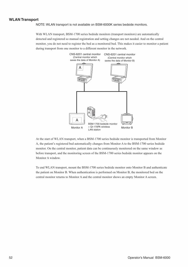
52 Operator’s Manual BSM-6000
WLAN TransportNOTE: WLAN transport is not available on BSM-6000K series bedside monitors.
With WLAN transport, BSM-1700 series bedside monitors (transport monitors) are automatically detected and registered so manual registration and setting changes are not needed. And on the central monitor, you do not need to register the bed as a monitored bed. This makes it easier to monitor a patient during transport from one monitor to a different monitor in the network.
Monitor BMonitor ABSM-1700 bedside monitor+ QI-170PA wireless LAN station
CNS-6201 central monitor (Central monitor which
saves the data of Monitor A)
A
A
A
CNS-6201 central monitor (Central monitor which
saves the data of Monitor B)
At the start of WLAN transport, when a BSM-1700 series bedside monitor is transported from Monitor A, the patient’s registered bed automatically changes from Monitor A to the BSM-1700 series bedside monitor. On the central monitor, patient data can be continuously monitored on the same window as before transport, and the monitoring screen of the BSM-1700 series bedside monitor appears on the Monitor A window.
To end WLAN transport, mount the BSM-1700 series bedside monitor onto Monitor B and authenticate the patient on Monitor B. When authentication is performed on Monitor B, the monitored bed on the central monitor returns to Monitor A and the central monitor shows an empty Monitor A screen.

Operator’s Manual BSM-6000 53
Using Transport Function with a Defibrillator
When a QI-670P interface is mounted on the bedside monitor, waveforms and numeric data can be received from a TEC-5600 series or TEC-8300 series defibrillator. Data from the defibrillator can be reviewed on the Review window.
Refer to the defibrillator operator’s manual together with this manual.
One of the following interfaces is also required when connecting a QI-670P interface. BSM-6301: QI-632P or QI-634P interfaceBSM-6501: QI-672P interfaceBSM-6701: QI-672P interface
TEC-8300 series defibrillator
TEC-5600 series defibrillator
QI-670P interface
BSM-6000 series bedside monitor
Data can be received via Bluetooth® communication
Or
NOTE:
• Transport function with a defibrillator can be used with BSM-6000 series bedside monitor
software version 05-41 or later. For the compatible defibrillator software versions, refer to the
defibrillator operator’s manual.
• While receiving data, do not turn off the bedside monitor or disconnect the USB cable of the
QI-670P interface from the bedside monitor. The bedside monitor may be damaged or data
may be lost.
• The filter setting of the waveform cannot be received from the defibrillator.
• Data communication with the QI-670P interface is only for TEC-5600 series and TEC-8300
series defibrillators.
• If a QI-670P interface that was connected to this bedside monitor is reconnected to a different
bedside monitor, all data in the interface is deleted.
• If the time setting on the bedside monitor and defibrillator are different, the time of the received
data is adjusted to the time on the bedside monitor.
• Do not use the QI-670P interface at the same time as a QI-320PA or QI-420PA wireless LAN
station.
• The received data from the defibrillator cannot be transferred to the central monitor.

54 Operator’s Manual BSM-6000
Alarms
WARNINGWhen an alarm occurs:
• Check the patient first and take necessary
measure to ensure patient’s safety.
• Remove the cause of the alarm.
• Check the alarm settings on the bedside monitor
and change the alarm settings if necessary.
WARNINGIf more than one medical equipment is used
together in the same facility, make sure all
equipments have the same alarm default settings
(alarm master). If the medical equipments have
different alarm default settings and when
initialized, the alarm settings differ with the other
equipments and alarm cannot be managed
appropriately in the facility. If using different alarm
default settings according to areas or wings in the
facility, manage the alarms appropriately.
WARNINGDo not diagnose a patient based on only the alarm
information of the bedside monitor. An alarm may
not be indicated due to alarm level or alarm on/off
setting and critical changes on the patient may be
overlooked.
WARNINGA physician must be within the range where he/she
can hear the alarm sound of the bedside monitor
while monitoring a patient on the bedside monitor.
If the physician cannot hear the alarm sound,
critical changes on the patient may be overlooked.
Alarm Types and LevelsThere are four types of alarms: vital signs, arrhythmias, technical and interbed alarms, and three alarm levels: crisis, warning and advisory.The monitor can indicate alarms both visually and audibly:• Alarm sound• Alarm message or highlighted numeric data on the screen• Alarm indicator: the alarm indicator indicates three alarm levels. CRISIS: Red blinking, WARNING: Yellow blinking, ADVISORY: Cyan or yellow lit
CRISIS: Patient is in critical condition and the patient’s life may be at risk. Immediate action must be taken. Electrodes or probe off, or incorrect lead or other cable connections may also cause this alarm.WARNING: Patient is in critical condition. Prompt action should be taken. Electrodes or probe off, or incorrect lead or other cable connections may also cause this alarm.ADVISORY: Electrodes, probe, cuff, lead and other cable connections or settings on the monitor are not appropriate for accurate measurement. Prompt action should be taken.
The priority and monitor action are different for each level.
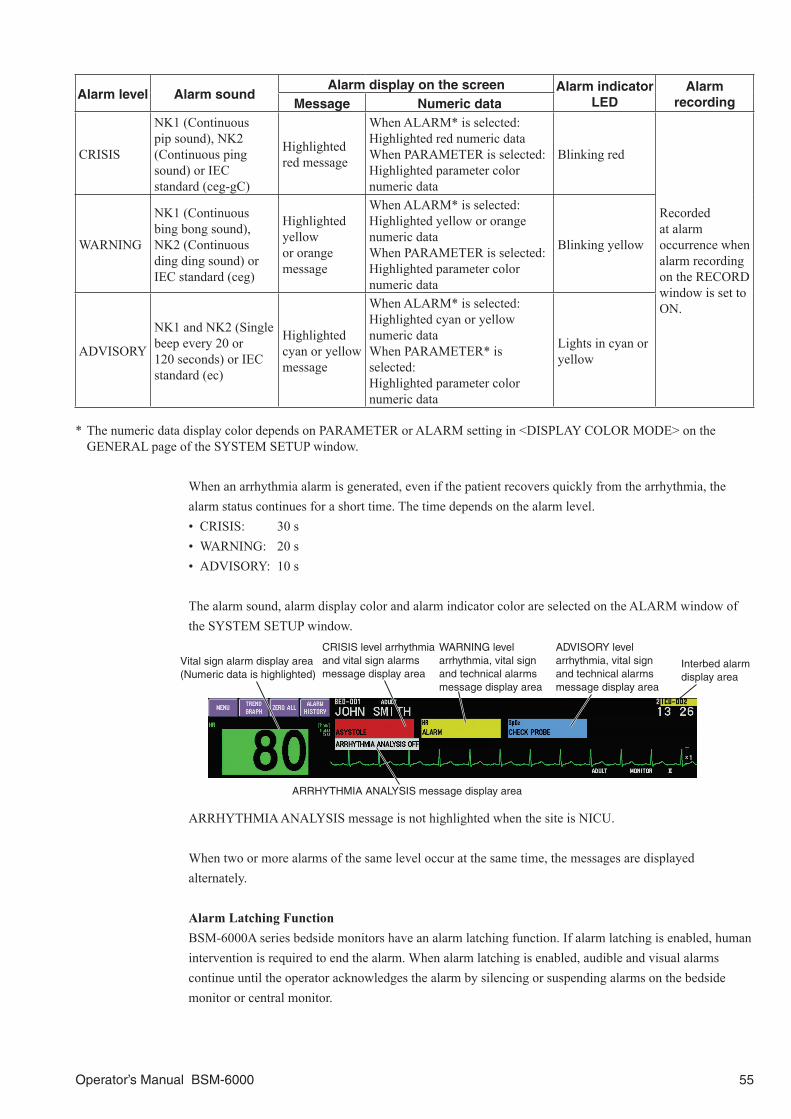
Operator’s Manual BSM-6000 55
Alarm level Alarm soundAlarm display on the screen Alarm indicator
LEDAlarm
recordingMessage Numeric data
CRISIS
NK1 (Continuous pip sound), NK2 (Continuous ping sound) or IEC standard (ceg-gC)
Highlighted red message
When ALARM* is selected:Highlighted red numeric dataWhen PARAMETER is selected:Highlighted parameter color numeric data
Blinking red
Recorded at alarm occurrence when alarm recording on the RECORD window is set to ON.
WARNING
NK1 (Continuous bing bong sound), NK2 (Continuous ding ding sound) or IEC standard (ceg)
Highlighted yellow or orange message
When ALARM* is selected:Highlighted yellow or orange numeric dataWhen PARAMETER is selected:Highlighted parameter color numeric data
Blinking yellow
ADVISORY
NK1 and NK2 (Single beep every 20 or 120 seconds) or IEC standard (ec)
Highlighted cyan or yellow message
When ALARM* is selected:Highlighted cyan or yellow numeric dataWhen PARAMETER* is selected:Highlighted parameter color numeric data
Lights in cyan or yellow
* The numeric data display color depends on PARAMETER or ALARM setting in <DISPLAY COLOR MODE> on the GENERAL page of the SYSTEM SETUP window.
When an arrhythmia alarm is generated, even if the patient recovers quickly from the arrhythmia, the alarm status continues for a short time. The time depends on the alarm level.• CRISIS: 30 s• WARNING: 20 s• ADVISORY: 10 s
The alarm sound, alarm display color and alarm indicator color are selected on the ALARM window of the SYSTEM SETUP window.
Interbed alarm display area
Vital sign alarm display area (Numeric data is highlighted)
WARNING level arrhythmia, vital sign and technical alarms message display area
CRISIS level arrhythmia and vital sign alarms message display area
ADVISORY level arrhythmia, vital sign and technical alarms message display area
ARRHYTHMIA ANALYSIS message display area
ARRHYTHMIA ANALYSIS message is not highlighted when the site is NICU.
When two or more alarms of the same level occur at the same time, the messages are displayed alternately.
Alarm Latching FunctionBSM-6000A series bedside monitors have an alarm latching function. If alarm latching is enabled, human intervention is required to end the alarm. When alarm latching is enabled, audible and visual alarms continue until the operator acknowledges the alarm by silencing or suspending alarms on the bedside monitor or central monitor.

56 Operator’s Manual BSM-6000
Alarm Control Marks Alarm is silenced by pressing the [Silence Alarms] key on the bedside monitor or [SILENCE ALARMS]
key on the remote control. Remaining minutes appears.
Alarms are suspended for a certain period.
Alarms are suspended infinitely or vital sign alarm limit is set to off.
Flow of Alarm Function
NONE
Suspend all alarms by touching the SUSPENDMONITORING key on the MENU window
Suspend all alarms by touching the SUSPEND ALARMS key on the MENU window
Silence Alarms
Suspend all alarms by touching the ALL ALARMS OFF or BYPASS key on the MENU window
The “ALL ALARMS OFF” message with all alarms off mark appears at the top of the screen. Or, the “BYPASS” and “ALL ALARMS OFF” message with all alarms off mark alternately appears at the top of the screen.No alarms are generated until the alarm function is re-activated.
The “SUSPEND MONITORING” and “ALARMS SUSPENDED”message with alarm suspended mark alternately appears at thetop of the screen. No alarms are generated until the system resumes monitoring or alarm function is re-activated.
The “ALARMS SUSPENDED --- min” message appears at thetop of the screen. No alarms are generated for a set period.
Identify the cause of the generated alarm and silence the alarm by pressing the [Silence Alarms] key
Identify the cause of the generated alarm and silence the alarm by touching the SILENCE ALARM key on the INTERBED window
Set the upper/lower limits on the ALARM LIMIT window or parameter window
Vital sign alarmArrhythmia
alarmTechnical
alarmInterbed
alarm
On
On
On
Off
Off
Off
Start monitoring
Sus
pend
all
alar
ms
inde
finite
ly
Sus
pend
all
alar
ms
for
a pe
riod
Ala
rm s
ettin
g an
d al
arm
beh
avio
rsS
ilenc
e an
ala
rm
ARRHYTHMIA ANALYSIS on or off on the ECG window
Set alarm on or off for each arrhythmia and alarm threshold on the ARRHYTH page of the ECG window or ARRHYTH ALARMS window
The “ALARM SILENCED --- min” message and the period in which the alarm is silenced appear at the top of the screen.
No alarms generated
Arrhythmia is not analyzed
No alarms generated even if arrhythmia is detected
Not connected
ConnectedNo interbed operation
No alarms generated
An alarm is generated when an alarm is detected on an interbed bed.
An alarm is generatedwhen a technical alarm is detected.
An alarm is generated when an arrhythmia is detected.
An alarm is generated when the alarm setting value is exceeded.
Connect the monitor to the network
Set interbed alarm on the INTERBED page of the SYSTEM SETUP window
ALL, CRISIS AND WARNING, CRISIS

Operator’s Manual BSM-6000 57
Silencing/Suspending AlarmsSilencing Alarms
When an alarm occurs, you can silence the alarm sound and indications for one, two or three minutes by pressing the [Silence Alarms] key on the bedside monitor or remote control. When a vital signs alarm other than NIBP or arrhythmia alarm is silenced, the alarm resumes after the alarm silence ends. When a technical alarm other than the following alarms is silenced, the alarm indication does not resume after the alarm silence ends. If the following alarms are silenced, the alarm resumes after the alarm silence ends.
• BATTERY ERROR • BATTERY WEAK• CO2 CHANGE ABSORBENT • CO2 LINE BLOCK• ECG CANNOT ANALYZE • EXTERNAL DEVICE ALARM• GAS LINE BLOCK • MULTILINK CONFIG ERROR• MULTILINK POWER ERROR • NIBP CUFF OCCLUSION• NIBP SAFETY CIRCUIT RUNNING • SpO2 CHANGE PROBE
When several alarms occur together and the [Silence Alarms] key is pressed, all alarms are silenced. To cancel vital sign or arrhythmia alarm silence, press the [Silence Alarms] key. <SILENCE ALARMS TIME> is set on the ALARM window of the SYSTEM SETUP window.
When the Monitor is Connected to the Central Monitor NetworkWhen the bedside monitor is connected to a central monitor network, all alarms other than NIBP alarm are temporarily silenced by touching the Silence Alarms key on the central monitor. Refer to the central monitor operator’s manual for details.
Suspending Alarms
All alarms can be suspended before they occur. This monitor has three types of alarm suspension:• Suspending all alarms for one, two or three minutes by touching the SUSPEND ALARMS key*2. For
example: for electrode replacement, etc. Alarm function resumes when the suspend alarm time elapses or the SUSPEND ALARMS key is
touched. <SUSPEND ALARMS TIME> is set on the ALARM window of the SYSTEM SETUP window.
When admitting or discharging a patient or when the monitor power is turned on, alarms are automatically suspended. Alarm function resumes when the monitoring conditions*1 are continuously met or the SUSPEND ALARMS key is touched.
• Suspending all alarms indefinitely by touching the BYPASS key (in OR mode only) or ALL ALARMS OFF key*3 on the MENU window. For example: suspend alarms when the patient is connected to a heart-lung machine.

58 Operator’s Manual BSM-6000
When the <ALARM INDICATOR LIT> on the ALARM window of the SYSTEM SETUP window is set to ON, the red lamp of the alarm indicator lights when all alarms are indefinitely suspended with the BYPASS or ALL ALARMS OFF key.
Alarm function resumes when the BYPASS or ALL ALARMS OFF key is touched.
• Suspending all alarms indefinitely by touching the SUSPEND MONITORING key*4. For example: suspend alarms while the patient is being examined. The “SUSPEND MONITORING” and “ALARMS SUSPENDED” messages appear on the screen alternately.
Alarm function resumes when the SUSPEND MONITORING key or SUSPEND ALARMS key is touched or the following monitoring conditions*1 are continuously met.
*1
Setting of <ALARM ACTIVATION DELAY> on the SYSTEM SETUP
windowCondition
AUTO
Alarm function activates when ECG, SpO2 or IBP* is monitored or NIBP** is measured and a value is displayed.* When SYS > DIA, the difference between these two values
is 3 mmHg and this status continues for more than 3 seconds.
** When SYS, DIA or MAP value is measured.
The alarm function is also recovered when the heart rate is 0.
1 min2 min3 min
When one of the following requirements is met.
1 ECG, SpO2 or IBP is continuously monitored for the selected time.
2 NIBP is measured (SYS, DIA or MAP value is measured).3 Heart rate becomes 0.
*2 SUSPEND ALARMS key is available when SUSPEND ALARMS is selected for <ALARM INACTIVATION> on the ALARM window of the SYSTEM SETUP window.
*3 ALL ALARMS OFF key is available when ALL ALARMS OFF is selected for <ALARM INACTIVATION> on the ALARM window of the SYSTEM SETUP window.
*4 SUSPEND MONITORING key is available when SUSPEND ALARMS is selected for <ALARM INACTIVATION> on the ALARM window of the SYSTEM SETUP window.
WARNINGDuring alarm suspension (“ALARMS
SUSPENDED” or “ALL ALARMS OFF” message
displayed), all alarms are turned off. Be careful
when you suspend the alarm.
WARNINGDo not turn all alarms off with the ALL ALARMS
OFF or BYPASS key when there is no medical
staff around the patient or when the patient is
connected to a ventilator.

Operator’s Manual BSM-6000 59
The alarm off key on the MENU window
Alarm off keys
ALARM INACTIVATION setting ICU/NICU site OR site
SUSPEND ALARMS
ALL ALARMS OFF
ALARMS OFF TYPE: BYPASS
ALARMS OFF TYPE: ALL ALARMS OFF
Alarm off functionSUSPEND MONITORING keyUse this key to temporarily stop patient monitoring for examination. When this key is touched, all alarms and NIBP STAT/SIM and auto measurements are suspended. Alarms resume when the SUSPEND MONITORING key is touched again or when the <ALARM ACTIVATION DELAY> condition is met.
SUSPEND ALARMS keyUse this key to suspend all alarms for the time set in <SUSPEND ALARMS TIME>.
BYPASS keyUse this key when the patient is connected to a heart-lung machine. When this key is touched, all alarms and NIBP STAT/SIM and auto measurements are indefinitely suspended. Touch the BYPASS key and touch the YES key on the confirmation window. Alarms resume when the BYPASS key is touched again.
ALL ALARMS OFF keyUse this key to suspend all alarms indefinitely. Touch the ALL ALARMS OFF key and touch the YES key on the confirmation window. Alarms resume when the ALL ALARMS OFF key is touched again.

60 Operator’s Manual BSM-6000
Canceling Technical AlarmsWhen you remove a sensor cable, probe cable, input unit or BSM-1700 series bedside monitor from the bedside monitor and press the [Silence Alarms] key, the technical alarm can be canceled. Touching the SUSPEND MONITORING, SUSPEND ALARMS, BYPASS and ALL ALARMS OFF keys also cancel the technical alarm.
Alarm Sound VolumeThe alarm sound volume is adjusted on the VOLUME window in the SETUP window.
Alarm RecordingWith an optional WS-671P recorder module, you can set the monitor to automatically record ECG waveforms and data when an alarm occurs. Set <ALARM RECORDING> on the OTHER page of the RECORD window in the SETUP window to ON. The waveforms of 8 seconds before to 12 seconds after the alarm occurrence are recorded.
Alarm SettingThere are vital sign upper/lower limit alarm and arrhythmia alarm settings. The vital sign alarm settings can be set on the ALARM LIMITS window. The arrhythmia alarm settings can be set on the ARRHYTH ALARMS window. The vital sign alarm setting can also be changed on the setting window for each parameter and the arrhythmia alarm setting can also be changed on the ARRHYTH window of the ECG window. The alarm settings are linked between different windows. For example, when a heart rate upper alarm limit is changed on the ALARM LIMITS window, the heart rate upper alarm limit is also changed on the ECG window. This section describes changing settings on the ALARM LIMITS and ARRHYTH ALARM windows.
The alarm returns to the master settings when:• The monitor power is off for more than 30 minutes when <SHOW ADMIT CONFIRMATION
WINDOW> is set to off in the SYSTEM CONFIGURATION screen.• The patient is admitted or discharged.• The “PATIENT TYPE” setting is changed on the ADMIT DISCHARGE window.

Operator’s Manual BSM-6000 61
WARNINGCheck the alarm settings when admitting a new
patient and whenever the patient condition
changes and change the alarm settings if
necessary. The alarm settings return to the alarm
master settings on the SYSTEM SETUP window
when:
• A patient is admitted or discharged.
• <SHOW ADMIT CONFIRMATION WINDOW> is
set to “Off” in the SYSTEM CONFIGURATION
screen and 30 minutes elapse after monitor
power off.
• “PATIENT TYPE” is changed on the ADMIT
DISCHARGE window.
WARNINGFor arrhythmia monitoring, set <ARRHYTHMIA
ANALYSIS> on the ECG window to ON.
Otherwise, there is no sound or indication for
arrhythmia alarms (except for ASYSTOLE).
WARNINGIf more than one medical equipment is used
together in the same facility, make sure all
equipments have the same alarm default settings
(alarm master). If the medical equipments have
different alarm default settings and when
initialized, the alarm settings differ with the other
equipments and alarm cannot be managed
appropriately in the facility. If using different alarm
default settings according to areas or wings in the
facility, manage the alarms appropriately.
WARNINGChange the anesthetic alarm settings by referring
to anesthetic agent reference information.
CAUTIONWhen the alarm limit is set to OFF, there will be no
alarm for that limit. Be careful when you set the
alarm limit to OFF.
CAUTIONWhen the alarm is turned OFF for an arrhythmia,
there will be no alarm for that arrhythmia type.
There is no message or mark to indicate that a
certain arrhythmia alarm is turned off. Therefore,
be careful when you turn off an arrhythmia alarm.
CAUTIONWhen the ZS-900P transmitter is attached to the
bedside monitor, check the alarm, arrhythmia and
monitoring settings on the central monitor or
telemetry system. The transmitter does not
transmit the alarm, arrhythmia and monitoring
setting information.

62 Operator’s Manual BSM-6000
NOTE: For BSM-6000A series bedside monitor, arrhythmia alarm whose priority is set to CRISIS
on the ALARM window of the SYSTEM SETUP window cannot be set to OFF.
When the Monitor is Connected to the Central Monitor NetworkWhen the bedside monitor is connected to a central monitor network, the alarm setting can also be changed from the central monitor. When the alarm setting is changed on the central monitor, check that the same setting on the bedside monitor is also changed.
Changing Vital Sign Upper/Lower Alarm Limits
There are three ways to change vital sign upper/lower alarm limits.• Change upper or lower alarm limits for each parameter individually.• Change upper or lower alarm limits for each parameter individually from the each parameter window.
Refer to the “Monitoring Parameters” section.• Set all alarm limits to the alarm master settings. The procedure is described in the User’s Guide Part I.
Changing Each Parameter Alarm Limits Individually1. Display the ALARM LIMITS window. Press the [Menu] key → ALARM LIMITS key.
Current measured value
Upper limit
Lower limit
Setting bar
Selected parameter
Upper limit slider
Lower limit slider
Touch the desired tab to change the displayed parameters
Current measured value
2. Touch the parameter key for the limit you want to change.
3. Touch or drag the sliders to the desired level on the setting bar. Use the or key to adjust the setting.
4. Press the [Home] key to return to the home screen.
Automatically Changing All Upper/Lower LimitsAll upper/lower alarm limits, including ST levels, can be set automatically according to the current measured parameter values. This function can be used on the Vital Signs page, All Vital Signs page and ST page.
NOTE: The alarm limit is not automatically changed for the parameter which is not monitored or
whose measured value is invalid.

Operator’s Manual BSM-6000 63
1. Display the ALARM LIMITS window. Press the [Menu] key → ALARM LIMITS key.
2. Touch the AUTOMATIC tab.
3. Touch YES to change all upper/lower alarm limits, including ST levels, according to the current measured values.
4. Check that the settings are appropriate.
5. Press the [Home] key to return to the home screen.
Automatic Setting Range
Parameter Upper limit value Lower limit value UnitECG HR HR×1.25 HR×0.75 beat/minPR PR×1.25 PR×0.75 count/minST ST+0.5 ST–0.5 mV
RespRR RR×1.25+4 RR×0.75–4 count/minAPNEA (60/RR)×2 – s
NIBP SYS, DIA, MAP NIBP×1.25+10 NIBP×0.75–10 mmHgSpO2 SpO2, SpO2-2 –*1 SpO2–5 %SpO2
IBP (ART, ART2, RAD, DORS, AO, FEM, UA, PAP, RVP, LVP, P1 to 7) SYS, DIA, MEAN IBP×1.25+10 IBP×0.75–10
mmHgIBP (UV, CVP, RAP, LAP, ICP, ICP2 to 4) MEAN IBP×1.25+5 IBP×0.75–5
Temp (Tb, Tskin, Tskin2, Tskin3, Trect, Tcore, Tnaso, Teso, Ttymp, Tblad, Taxil, T1 to 4) TEMP+0.5 TEMP–0.5
°C∆T ∆T+0.5 –
O2O2 (I) O2 (I)×1.1 O2 (I)×0.9
%O2 (E) O2 (E)×1.25 O2 (E)×0.75
CO2CO2 (I) CO2 (I)×1.25 –
mmHgETCO2 ETCO2×1.25 ETCO2×0.75

64 Operator’s Manual BSM-6000
Parameter Upper limit value Lower limit value Unit
N2ON2O (I) N2O (I)×1.2+5 N2O (I)×0.8–5
%
N2O (E) N2O (E)×1.2+5 N2O (E)×0.8–5
HALHAL (I) HAL (I)×1.1+0.5 HAL (I)×0.9–0.5HAL (E) HAL (E)×1.1+0.5 HAL (E)×0.9–0.5
ISOISO (I) ISO (I)×1.1+0.5 ISO (I)×0.9–0.5ISO (E) ISO (E)×1.1+0.5 ISO (E)×0.9–0.5
ENFENF (I) ENF (I)×1.1+0.5 ENF (I)×0.9–0.5ENF (E) ENF (E)×1.1+0.5 ENF (E)×0.9–0.5
SEVSEV (I) SEV (I)×1.1+0.5 SEV (I)×0.9–0.5
%SEV (E) SEV (E)×1.1+0.5 SEV (E)×0.9–0.5
DESDES (I) DES (I)×1.2+0.5 DES (I)×0.8–0.5DES (E) DES (E)×1.2+0.5 DES (E)×0.8–0.5
MV*2 MV×1.25 MV×0.75 L/minPpeak*2 Ppeak×1.25 Ppeak×0.75
cmH2OPEEP*2 PEEP×1.25 PEEP×0.75BIS Off 40 –
EEGSEF SEF×1.25+2.0 SEF×0.75–2.0 HzTP TP×1.25+0.20 TP×0.75–0.20 nW
*1 Not automatically set (the upper limit value is greater than the lower limit value).*2 These parameter alarms are not available on BSM-6000A series.
Changing All Alarm Limits to the Alarm Master SettingsAll alarms, including arrhythmia alarm, can be set to a group of alarm settings called the alarm master. The alarm masters are set by the administrator on the MASTER window of the SYSTEM SETUP window.
NOTE: The vital sign upper/lower limits settings and arrhythmia alarm settings are changed
on the different alarm master page but the same master setting is applied to the both settings.
(i.e., if the master for the upper/lower limits is changed, the master for the arrhythmia alarm is
changed to the same master as the upper/lower limits.)
1. Display the ALARM MASTER page. The “APPLY SETTINGS FROM MASTER?” message appears.
Press the [Menu] key → ALARM LIMITS or ARRHYTH ALARMS key → ALARM MASTER tab.
<NUMBER OF MASTER SETTINGS> is set to “1” <NUMBER OF MASTER SETTINGS> is set to “3”
2. Select a master when the <NUMBER OF MASTER SETTINGS> is set to “3” on the MASTER window of the SYSTEM SETUP window.
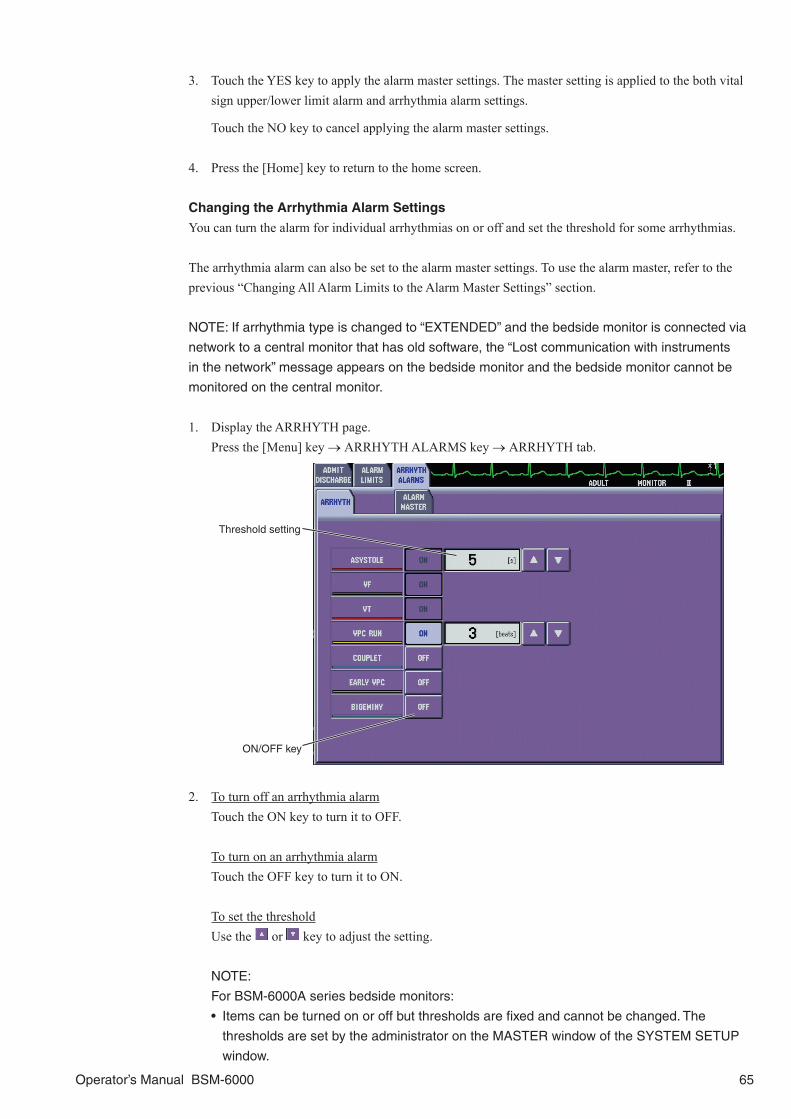
Operator’s Manual BSM-6000 65
3. Touch the YES key to apply the alarm master settings. The master setting is applied to the both vital sign upper/lower limit alarm and arrhythmia alarm settings.
Touch the NO key to cancel applying the alarm master settings.
4. Press the [Home] key to return to the home screen.
Changing the Arrhythmia Alarm Settings
You can turn the alarm for individual arrhythmias on or off and set the threshold for some arrhythmias.
The arrhythmia alarm can also be set to the alarm master settings. To use the alarm master, refer to the previous “Changing All Alarm Limits to the Alarm Master Settings” section.
NOTE: If arrhythmia type is changed to “EXTENDED” and the bedside monitor is connected via
network to a central monitor that has old software, the “Lost communication with instruments
in the network” message appears on the bedside monitor and the bedside monitor cannot be
monitored on the central monitor.
1. Display the ARRHYTH page. Press the [Menu] key → ARRHYTH ALARMS key → ARRHYTH tab.
ON/OFF key
Threshold setting
2. To turn off an arrhythmia alarm Touch the ON key to turn it to OFF.
To turn on an arrhythmia alarm Touch the OFF key to turn it to ON.
To set the thresholdUse the or key to adjust the setting.
NOTE:
For BSM-6000A series bedside monitors:
• Items can be turned on or off but thresholds are fixed and cannot be changed. The
thresholds are set by the administrator on the MASTER window of the SYSTEM SETUP
window.

66 Operator’s Manual BSM-6000
• Arrhythmia alarm whose alarm level is set to CRISIS on the ALARM window of the
SYSTEM SETUP window, the alarm cannot be set to OFF.
• When the “EXT TACHY” or “EXT BRADY” alarm is set to OFF, the heart rate limit range is
15 to 300 beat/min or OFF.
When EXTENDED is selected for the <ARRHYTHMIA TYPE> on the ECG page of the PARAMETERS window in the SYSTEM SETUP window, touch the threshold to display the ARRHYTH window and adjust the setting.
3. Press the [Home] key to return to the home screen.
Alarm EscalationIf the APNEA, SpO2, ECG CHECK ELECTRODES, CANNOT ANALYZE or SpO2 CHECK PROBE alarm occurs and no action is taken for a selected time, the alarm level can be escalated. If an SpO2 value drops below a set level for a selected duration, the alarm level can also be escalated.

Operator’s Manual BSM-6000 67
Interbed AlarmWhen the bedside monitor is connected to a central monitor network, the bedside monitor can display monitoring data and alarms of up to 20 other beds in the network on the INTERBED window if the other beds are registered as “interbed” bed. When an interbed alarm occurs, the monitor acts as follows. The monitor action depends on the INTERBED ALARMS TO DISPLAY setting on the SYSTEM SETUP window. Refer to the “INTERBED Window” section of this manual and Section 3 of the Administrator’s Guide for details.
NOTE:
• Parameters which cannot be measured on this monitor are displayed as “ALARM”.
• The interbed alarm for another bed is lower level than any other alarm for this bed. Therefore,
the interbed alarm might not be indicated during an alarm for this bed.
INTERBED ALARMS TO DISPLAY Setting
ALL, CRISIS AND WARNING,CRISIS
NONE
Alarm Indicator Off
Alarm SoundThree continuous ping sounds (only when the alarm is detected)
No sound
Home Screen
The bed ID of interbed alarm bed is displayed in the upper right corner. When two or more alarms are detected, the bed IDs alternate.
The bed ID is highlighted in the alarm priority color.*1 The bed ID is displayed in white.
After is touched. Bed ID: remain highlighted Bed ID: remain in white font
Multiple Beds Window
Interbed alarm message is displayed
The bed ID and interbed alarm message is highlighted in the alarm priority color.*1*2
After is touched.Bed ID: displayed in whiteAlarm: remain highlighted
Individual Bed Window
The alarm message and bed ID are highlighted in the alarm priority color. When the vital sign alarm occurs, the measurement value is also highlighted.
The bed ID and alarm message is highlighted in the alarm priority color.*1*2
After is touched.Bed ID: displayed in whiteAlarm: remain highlighted
*1 The alarm priority is displayed as set on the interbed bed. The alarm priority color is set at <ALARM PRIORITY COLOR> on the DISPLAY/SOUND page of the ALARM window of the SYSTEM SETUP screen. Refer to “ALARM Window” in Section 3 of the Administrator’s Guide.
*2 When the alarm of crisis or warning level occur, the message blinks.

68 Operator’s Manual BSM-6000
Review Windows
GeneralYou can review saved data on the following review windows. You can expand the memory of the monitor from 128 MB to 1 GB with the optional QM-601P memory card. The parentheses show the capacity when the QM-601P memory card is installed in the monitor.
• TREND window GRAPH page: Displays the trendgraph of the past 24 hours (72 hours). TABLE page: Displays the vital sign data of the past 24 hours (72 hours). NIBP TREND page: Displays vital sign data at the NIBP measurement. Up to 512 files (1,024
files) can be saved. HEMO TREND page: Displays the hemodynamic data when CO is measured. Up to 512 files
(1,024 files) can be saved. LUNG TREND page: Displays data acquired at the lung function measurement. Up to 128 files
(128 files) can be saved.• RECALL window: Displays arrhythmia waveforms of 4 seconds before and 4 seconds after
the arrhythmia detection. Up to 8,192 files (16,384 files) can be saved.• ALARM HISTORY window: Displays the table of vital sign alarms and arrhythmia alarms. Up 8,192
files (16,384 files) can be saved.• FULL DISC window: Displays up to 24 hours (72 hours) of compressed and expanded
waveforms of up to 5 parameters.• ST window: Displays the ST level waveforms of the past 24 hours (72 hours). All
monitoring ECG can be saved. ST window is available when the site setting is OR or ICU.
• 12 LEAD window: Displays the 12 lead analysis result data of up to 6 files (18 files). Refer to the “12 LEAD/12 LEAD ANALYSIS Windows” section.
• OCRG window: Displays the OCRG trendgraph of the past 24 hours (72 hours). OCRG window is available when the site setting is NICU.
• aEEG window: Displays 2 aEEG traces of the past 24 hours (72 hours). aEEG is only available when EEG is monitored with AE-918P neuro unit with software version 02-01 or later.
NOTE:
• When <DATA TRANSPORT USING INPUT UNIT> is set to DISABLE, and <SHOW ADMIT
CONFIRMATION WINDOW> is set to OFF in the SYSTEM CONFIGURATION screen, the
stored data remains in memory for about 30 minutes after the power is turned off. After 30
minutes, the stored data is lost. When <DATA TRANSPORT USING INPUT UNIT> is set to
ENABLE, the patient data and settings are always stored.
• The oldest file is deleted when the maximum number of files are saved.
• Do not disconnect the power cord while the monitor power is on. Data may be lost.
• On BSM-6000A series, the 12 LEAD ANALYSIS window is not available when the site mode is
NICU and 12 LEAD ANALYSIS is set to Off in the SYSTEM CONFIGURATION screen. Refer
to “SITE Window” in Section 2 of the Administrator’s Guide.
• On BSM-6301A/K, the aEEG window is not available.

Operator’s Manual BSM-6000 69
Event Bar
An event bar near the bottom of the review window shows events during displayed review time. The event bar and review window are synchronized. They have the same time scale and scroll together.
You can display up to four types of events.• Arrhythmia alarms• Technical alarms• Vital sign alarms• Monitoring operations: silence alarm, suspend alarms, all alarms off, bypass, and suspend monitoring
Example: GRAPH 1 page
Event bar
Date and time at the cursor
Event at the cursor(parameter and message)
CursorThe cursor on the event bar is synchronized with the cursor on the review window. When the cursor is on the latest time, the review window and event bar are continuously refreshed.
EventsAlarm events are displayed in the alarm priority color.
Time scaleTouch or to change the time scale of the event bar. (1, 2, 4, 8 or 24 hours)
Event keys : Moves the cursor to the previous event. : Moves the cursor to left. : Moves the cursor to right. : Move the cursor to the next event.
Scroll keys : Scrolls to the oldest time. : Scrolls to the latest time. : Scrolls one page back. : Scrolls one page forward.
Time

70 Operator’s Manual BSM-6000
TREND WindowGRAPH 1, GRAPH 2, GRAPH 3 Page
There are 3 trend graph pages. Each page displays up to 6 parameters of the past 24 hours. With the optional QM-601P memory card, data of past 72 hours can be saved.
The screen example is when 2 parameters are selected on the SETTINGS window. On the SETTINGS window, you can select parameters and on the SCALE window you can select each scale for the trendgraph display. To change the time threshold for the apnea trendgraph, select the interval in <APNEA TREND TIME> box on the SETTINGS window. You can select to display maximum and minimum values or mean values for the trendgraph display.
Press the [Menu] key → TREND key → GRAPH 1, GRAPH 2 or GRAPH 3 tab to display the TREND GRAPH page.
Cursor (can be dragged with your finger)
Changes the trendgraph page.
Displays other review windows.
Displays the maximum and minimum values on the trendgraph.
Displays mean values on the trendgraph.
Records or prints the displayed trend graph on the WS-671P recorder module or connected network printer.
Scale
Displays the SETTINGS window.
Displays the SCALE SETUP window.
Event bar
Displays the parameter selected on the SETTINGS window.

Operator’s Manual BSM-6000 71
TABLE 1, TABLE 2, TABLE 3 Page
There are 3 table pages. Each page displays the vital sign data of the past 24 hours. With the optional QM-601P memory card, data of past 72 hours can be saved.
The data of all monitoring parameters can be displayed on the TREND TABLE page. The data of the selected parameters at the selected interval are displayed. Select the parameters to be displayed on the SETTINGS window on the TABLE 1 to TABLE 3 page.
Press the [Menu] key → TREND key → TABLE 1, TABLE 2 or TABLE 3 tab to display the TREND TABLE page.
Displays the parameters selected in the SETTINGS window.
Date and time
Changes the trend data page.
Displays other review windows.
Records or prints the trend data of the selected time period on the WS-671P recorder module or connected network printer.
Displays the SETTINGS window.
Displays the INTERVAL SETUP window.
Event bar
Selected file

72 Operator’s Manual BSM-6000
NIBP TREND Page
The NIBP TREND page displays data of the selected parameters at the NIBP measurement. Select the parameters to be displayed on the SETTINGS window of the NIBP TREND page. Displays the vital sign data at the NIBP measurement of up to 512 files. With the optional QM-601P memory card, data of up to 1,024 files can be saved.
Press the [Menu] key → TREND key → NIBP TREND tab to display the NIBP TREND page.
Displays other review windows.
Date and time
Selected file
Displays the SETTINGS window.
Displays the parameters selected in the SETTINGS window.
Records or prints the NIBP data of the selected time period on the WS-671P recorder module or connected network printer.
Event bar
NOTE: The HR on the NIBP TREND page is the HR at the completion of NIBP measurement.
The HR on the TABLE page and NIBP TREND page may be different.

Operator’s Manual BSM-6000 73
HEMO TREND Page
The HEMO TREND page displays the hemodynamics table when cardiac output is measured and the measured values are added to the hemodynamics table. When cardiac output is monitored by the CCO monitor, measured values are also added to the hemodynamics table. Up to 512 files of the hemodynamic data are displayed when CO is monitored. With the optional QM-601P memory card, data of up to 1,024 files can be saved.
Press the [Menu] key → TREND key → HEMO TREND tab to display the HEMO TREND page.
Records or prints the hemodynamics data of the selected time period on the WS-671P recorder module or connected network printer.
Event bar
Displays other review windows.
Scroll to display other parameters.
Displays other trend windows.Selected file
Measured date and time
Adding the Acquired Data to the Hemodynamics Table
The acquired CO data can be added to the hemodynamics table in the HEMO TREND page. When data is added to the hemodynamics table, the data disappears from the home screen and CO window. “- - -” appears on the CO data display area on the screen.
1. Display the RESULT page of the CO window. Press the [Menu] key → CO key → RESULT tab.

74 Operator’s Manual BSM-6000
2. Touch the ADD key under <ADD TO HEMO TREND>. The data on the RESULT page is registered to the hemodynamics table (in the HEMO TREND page).
3. Touch the SHOW key under <SHOW HEMO TREND> to display the HEMO TREND page. The registered CO data is displayed in the HEMO TREND page.
Even when CO is not monitored, CCO and CCI data can be added to the hemodynamics table if CCO is monitored.
LUNG TREND Page
The LUNG TREND page displays data acquired at the lung function measurement from the LUNG FUNCTION window. The files of past 24 hours or up to 128 files can be saved. Refer to the “DRUG/LUNG FUNCTION Windows” section.
Press the [Menu] key → TREND key → LUNG TREND tab to display the LUNG TREND page.
Selected file
Records or prints the lung trend data of the selected time period on the WS-671P recorder module or connected network printer.
Displays other review windows.
Date and time
Displays data from LUNG FUNCTION window.
Event bar

Operator’s Manual BSM-6000 75
RECALL WindowARRHYTH HISTORY Page
Up to 8,192 files can be saved for arrhythmias. 8 second ECG is saved for each recall file. With the optional QM-601P memory card, data of up to 16,384 files can be saved.
To create arrhythmia recall files:• <ARRHYTHMIA ANALYSIS> on the ECG window must be set to ON.• The type of arrhythmias you want to save as files must be selected on the ARRHYTHMIA EVENT
SETUP window on the RECALL window.
Press the [Menu] key → RECALL key to display the ARRHYTH HISTORY page.
Scroll to display other recall files.
Recall file
Arrhythmia type
Date and time of file creation
Compressed ECG of the recall file
Displays other review windows.
Records or prints the displayed arrhythmia history data on the WS-671P recorder module or connected network printer.
Displays the ARRHYTHMIA EVENT SETUP window.
Selected file
Event bar
The recall file of past 24 hours can be displayed on the ARRYTH HISTORY page. Use the scroll bar to display other files. Touch the desired file to display the actual size ECG.

76 Operator’s Manual BSM-6000
Actual Size ECGThe ARRHYTH HISTORY page displays the actual size ECG of the selected recall file with the ECG of one before and one after the selected file.
Selected file
Records or prints the displayed actual size ECG on the WS-671P recorder module or connected network printer.
Displays other review windows.
File before the selected file
Date and time of file creation
Lead
ECG sensitivity
Vital signs numeric values at the time the recall file is created.
Stored recall files time range
Event bar
ALARM HISTORY WindowALARM HISTORY Page
Displays the history of the past 24 hours. Up to 8,192 files can be saved. With the optional QM-601P memory card, data of up to 16,384 files can be saved.
Press the [Menu] key → ALARM HISTORY key to display the ALARM HISTORY page.
Scrolls file.
Date and time of alarm occurrence
Parameter
Alarm message
Records the alarm history data of the selected time period on the WS-671P recorder module.
Alarm type
Selected file
Event bar
Displays other review windows.

Operator’s Manual BSM-6000 77
FULL DISC WindowFULL DISC Page
Up to 5 parameter waveforms can be saved for the past 24 hours. With the optional QM-601P memory card, data of past 72 hours can be saved. Up to 4 parameters waveforms can be displayed. The full disclosure waveforms can be zoomed in to display the enlarged waveforms. Select the parameters for the waveform to be saved as the full disclosure on the SETTINGS window.
Press the [Menu] key → FULL DISC key to display the FULL DISC page.
Full Disclosure WaveformTouch to display the 6 seconds of enlarged waveforms. Touch again to restore the previous display.
Scrolls time.
Displays other review windows.
Time of file creation ECG lead
Vital sign numeric values at the time the recall file is created
Stored recall files time range
60 second full disclosure waveform
Displays the Zoom In window for the selected waveform. Every touch of the key changes the display range from 60 → 30 →12 → 6 seconds of waveforms.
Displays the DISPLAY/SAVE and WAVEFORMS settings window.
Records or prints the displayed full disclosure data on the WS-671P recorder module or connected network printer.
Event bar

78 Operator’s Manual BSM-6000
Zoom In WindowThe full disclosure waveform can be displayed in actual size.
Scrolls time.
6 second actual size waveformDisplays other review windows.
ECG lead
Vital sign numeric values at the time the recall file is created
Displays the DISPLAY/SAVE and WAVEFORMS settings window.
Records or prints the displayed full disclosure data on the WS-671P recorder module or connected network printer.
Displays the ZOOM OUT window to display the compressed traces window.
ECG sensitivity
Time of file creation
Stored full disclosure files time range
Selected ECG waveforms are highlighted.
Event bar
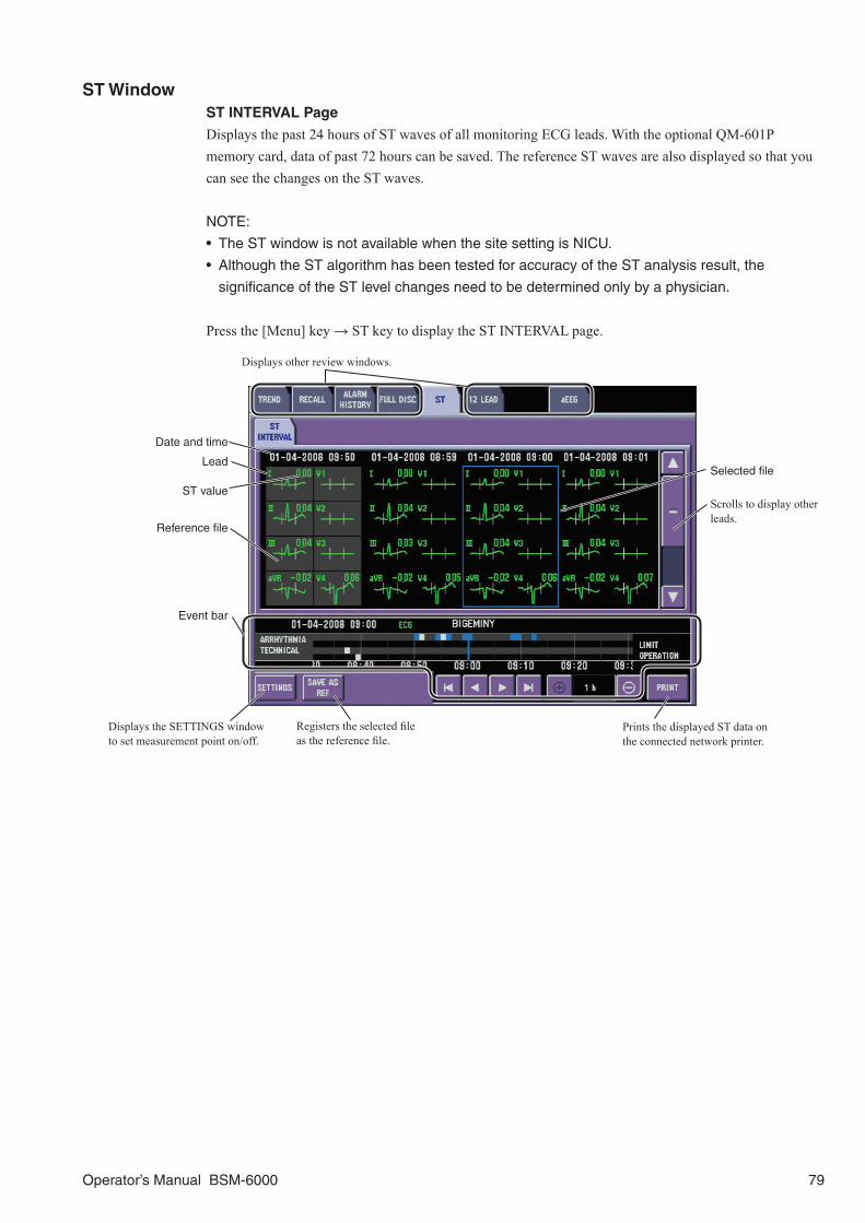
Operator’s Manual BSM-6000 79
ST WindowST INTERVAL Page
Displays the past 24 hours of ST waves of all monitoring ECG leads. With the optional QM-601P memory card, data of past 72 hours can be saved. The reference ST waves are also displayed so that you can see the changes on the ST waves.
NOTE:
• The ST window is not available when the site setting is NICU.
• Although the ST algorithm has been tested for accuracy of the ST analysis result, the
significance of the ST level changes need to be determined only by a physician.
Press the [Menu] key → ST key to display the ST INTERVAL page.
Displays other review windows.
Reference file
Scrolls to display other leads.
Registers the selected file as the reference file.
ST value
Date and time
Lead
Displays the SETTINGS window to set measurement point on/off.
Prints the displayed ST data on the connected network printer.
Selected file
Event bar

80 Operator’s Manual BSM-6000
OCRG WindowDisplays the past 24 hours of OCRG trendgraph. With the optional QM-601P memory card, data of past 72 hours can be saved.
On the SETTINGS window, you can select the OCRG trendgraph type of 1 cm/min or 3 cm/min and on the SCALE window, you can select the scale for the heart rate, SpO2 and impedance respiration trendgraph display.
NOTE: The OCRG window is available only when the site setting is NICU.
Press the [Menu] key → OCRG key to display the OCRG window.
Event bar
Cursor (can be dragged with your finger)Displays other review windows.
Records or prints the displayed trend graph on the WS-671P recorder module or connected network printer.
Scale
Displays the SETTINGS window.
Displays the SCALE SETUP window.

Operator’s Manual BSM-6000 81
aEEG WindowNOTE: aEEG window is not available on BSM-6301A/K.
Displays 2 aEEG traces on the aEEG window of the past 24 hours. With the optional QM-601P memory card, data of past 72 hours can be saved. aEEG is only available when EEG is monitored with an AE-918P neuro unit with software version 02-01 or later.
Press the [Menu] key → aEEG key to display the aEEG window.
To display aEEG (amplitude integrated electroencephalography), EEG must be monitored with an AE-918P neuro unit. aEEG of 2 channels monitored by the neuro unit is displayed on the aEEG window. When EEG is selected for the parameters to be saved as full disclosure on the FULL DISC window, the actual size EEG of the full disclosure is displayed in the lower part of the aEEG window.
aEEG and EEG can be recorded or printed by specifying the recording or printing range.
Cursor (can be dragged with your finger)Displays other review windows.
Records or prints the displayed aEEG on the WS-671P recorder module or connected network printer.
Displays the SETTINGS window.
aEEG traces
6 s EEG full disclosure waveforms in actual size at the cursor on aEEG
Scrolls aEEG traces up/down.
Event bar

12 LEAD/12 LEAD ANALYSIS Windows
GeneralWhen 12 lead ECG is monitored, ECG can be analyzed on the 12 LEAD ANALYSIS window and the analysis result and clinical findings can be displayed on the 12 LEAD window. Up to 6 files can be saved.With the optional QM-601P memory card, data of up to 18 files can be saved.
The 12 LEAD window has the following pages to display the analysis result and clinical findings.• 12 LEAD page for displaying the 12 lead analysis result data.• ANALYSIS WAVE page for displaying ECG waveforms used for analysis.• AVERAGE WAVE page for displaying averaged ECG waveforms.• REPORT page for displaying clinical findings.
NOTE:
• 12 lead analysis is not available when an AY-660P input unit is used.
• On BSM-6000A series, the 12 LEAD and 12 LEAD ANALYSIS windows are not available
when the site setting is NICU and 12 LEAD ANALYSIS is set to Off in the SYSTEM
CONFIGURATION screen. Refer to Section 2 of the Administrator’s Guide.
• ECG must be monitored with 10 electrodes to perform 12 lead ECG interpretation. ECG
cannot be analyzed when monitoring with 3 or 6 electrodes.
• The oldest file is deleted when the maximum number of files are created.
• The stored data remains in memory for about 30 minutes after the power is turned off. After 30
minutes, the stored data is lost.
• Do not disconnect the power cord while the monitor power is on. Data may be lost.
82 Operator’s Manual BSM-6000

12 LEAD ANALYSIS WindowPerforming 12 Lead ECG Interpretation
WARNINGDo not use 12 lead ECG interpretation results and
measured values from the Mason-Likar
modification for diagnosis because the limb
electrode placement is not the same as the
standard 12 lead ECG. This may cause wrong
diagnosis since 12 lead ECG interpretation of this
monitor is based on the standard 12 lead ECG.
CAUTION• The 12 lead ECG interpretation is performed
for acquired ECG waveforms only and does not
reflect all conditions of the patient. The results
of the analysis might not correspond to the
judgement of a physician.
• Overall judgement must be performed by the
physician, referring to the analysis result, clinical
findings and other examination results. After
the physician’s overall judgement, the analysis
results should be signed or initialed by the
physician.
CAUTIONWhen the gender is not specified, 12 lead ECG
interpretation is performed with the patient as
male.
CAUTIONWhen the date of birth or age is not entered, 12
lead ECG interpretation is performed with the
patient as 35 years old.
NOTE:
• When electrodes are not attached to the limbs, the analysis result concerning the ECG axis
(such as axis deviation) may differ from the analysis with electrodes attached to limbs.
• When analyzing the pacemaker patient, set the pacing spike detection on the ECG window to
ON.
• Refer to the ECAPS12C ECG Interpretation Program User’s Guide for details about the
analysis and the clinical findings.
1. Display the PATIENT INFORMATION window and check that the age and gender are correct. Press the [Menu] key → 12 LEAD ANALYSIS key → PATIENT INFO key.
2. Check that the electrodes are attached to the patient and leads are connected appropriately.
3. Display the 12 LEAD ANALYSIS window and check that ECGs on the window are stable. Press the [Menu] key → 12 LEAD ANALYSIS key.
NOTE: When the age and/or gender is not entered, the “ENTER DATE OF BIRTH AND
GENDER” message appears.
Operator’s Manual BSM-6000 83
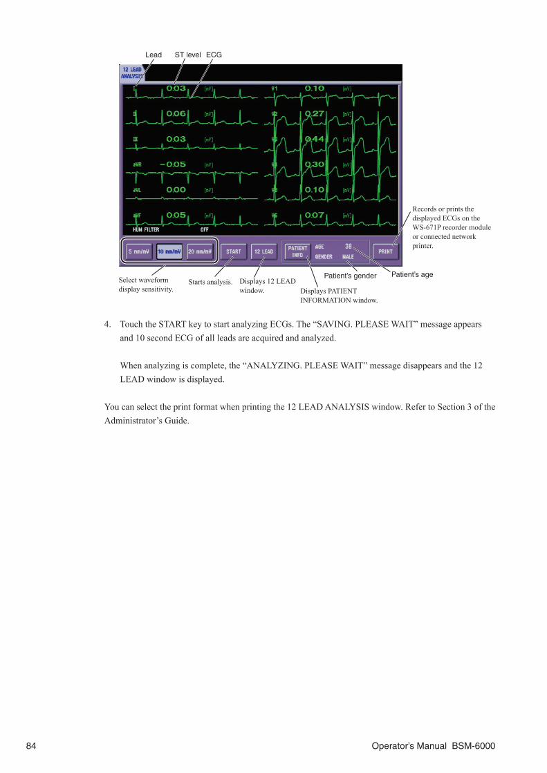
Select waveform display sensitivity.
Starts analysis.
ECGST levelLead
Patient’s gender Patient’s ageDisplays 12 LEAD window. Displays PATIENT
INFORMATION window.
Records or prints the displayed ECGs on the WS-671P recorder module or connected network printer.
4. Touch the START key to start analyzing ECGs. The “SAVING. PLEASE WAIT” message appears and 10 second ECG of all leads are acquired and analyzed.
When analyzing is complete, the “ANALYZING. PLEASE WAIT” message disappears and the 12 LEAD window is displayed.
You can select the print format when printing the 12 LEAD ANALYSIS window. Refer to Section 3 of the Administrator’s Guide.
84 Operator’s Manual BSM-6000

12 LEAD Window
Viewing the 12 Lead Analysis Result
To see the 12 lead analysis result data, touch the 12 LEAD tab.
Selected file
Records the displayed ECGs on the WS-671P recorder module.
Event bar
Scroll to display other 12 lead data.
To see the analyzed waveforms, touch the ANALYSIS WAVE tab. About 2 seconds of the ECG of each lead and 10 seconds of rhythm waveform (lead II) used for the analysis are displayed.
Analyzed ECG (about 2 s)
ST level
Lead
Date and time
Patient’s age
Rhythm waveform (about 10 s)
Patient’s gender
Records or prints the displayed ECGs on the WS-671P recorder module or connected network printer.
Event bar
Operator’s Manual BSM-6000 85

To see the interpretation result, touch the REPORT tab.Patient’s gender Patient’s age
Measured values
Date and time
Records or prints the displayed ECGs on the WS-671P recorder module or connected network printer.
Finding code and analysis results
Event bar
To see the averaged ECGs, touch the AVERAGE WAVE tab. The cursors appear to indicate the P wave start and end points, QRS start and end points and T wave end points.
Averaged ECG
Cursor
Prints the displayed ECGs on the connected network printer.
Event bar
86 Operator’s Manual BSM-6000

DRUG/LUNG FUNCTION Windows
DRUG WindowOn the DRUG window, you can calculate the flow rates and dosages for medication titrations. The flow rate is calculated from the following equation. The dosage can also be calculated when the flow rate is known.
Dosage × Patient Weight × Solution AmountFlow rate = Drug Amount
The DRUG window has the following windows.• DRUG window for entering drug name, registering drugs and the units other than the factory default
settings• SETTINGS window for entering drug amount (AMOUNT), solution amount (VOLUME), dosage
(DOSE), flow rate (SAMPLE RATE), patient weight and dose step• DOSE window for displaying the table of the selected drug titration
NOTE:
• When using the DRUG window for the first time after shipment or after settings are initialized,
you must set the drug names and other settings.
• When the patient weight is changed on the ADMIT page of the ADMIT DISCHARGE window,
the titration is automatically recalculated with the new weight.
Select drug from here.
Displays EDIT window for entering drug name and dose unit.
17 drugs and drug amount, solution amount, dosage and dose step for each drug are preset on the monitor. You can set four other drugs on the DRUG window and change the settings on the EDIT window. The following drug names are preset.• Amrinone • Aminophylline • Bretylium• Dobutamine • Dopamine • Epinephrine• Heparin • Insulin • Isoproterenol• Lidocaine • Nitroglycerin • Nitroprusside• Norepinephrine • Phenylephrine • Procainamide• Streptokinase • tPA
Operator’s Manual BSM-6000 87

Using Drug Calculation1. Display the DRUG window. Press the [Menu] key → DRUG key.
2. On the DRUG window, select the drug name.
3. On the SETTINGS window, enter other necessary settings. For drugs which need patient weight to calculate the flow rate, enter the patient weight on the ADMIT page of the ADMIT DISCHARGE window or the SETTINGS window of the DRUG window.
Use the numeric keys to enter values. Touch the ENT key to register the entered value.
Touch a key to enter value.
4. Touch the DOSE tab to display the titration table. The titration values calculated from the settings on the SETTINGS window are displayed in the table.
Prints the displayed dose table and settings on the WS-671P recorder module or network printer.
Select the dose step.
88 Operator’s Manual BSM-6000

Registering DrugsWhen using a drug other than the 17 preset drugs, assign a drug name and dose unit to Drug A, B, C or D on the DRUG window. When the dosage unit is set, the sample rate unit is automatically set.
Use the keyboard to enter drug name.
Select a dose unit.
Entered drug name
LUNG FUNCTION WindowThere are two windows. The DATA ENTRY window calculates the patient’s respiration dynamics and the LUNG FUNCTION window displays the calculation result. The following data required for this calculation is automatically acquired from the monitoring parameters when the window is opened.• Patient’s height and weight entered on the ADMIT page of the ADMIT DISCHARGE window• CCO value (When CCO is measured, the CCO value is used as the CO value)• O2 when O2 or anesthetic gas is monitored
Calculating the LUNG FUNCTION1. Display the DATA ENTRY window. Press the [Menu] key → LUNG FUNCTION key → DATA ENTRY tab.
Use the numeric keypad to change the values in the DATA ENTRY column on the LUNG FUNCTION window.
Touch key to enter value.
Operator’s Manual BSM-6000 89

2. If necessary, change values using the numeric keypad. When height or weight is changed, the same setting on the ADMIT page of the ADMIT DISCHARGE window and windows which use height and weight are also changed. Touch ENT key to register the entered value. The respiration dynamics are recalculated according to the entered values.
3. Touch the LUNG FUNCTION tab to display the LUNG FUNCTION window.
The values in this column are automatically calculated according to the values in the DATA ENTRY column.
Adds the values on the window to the LUNG TREND page in the TREND window.
The values in this column can be changed on the DATA ENTRY window.
Records the displayed data on the WS-671P recorder module.
Shows the LUNG TREND page in the TREND window.
4. Touch the ADD key to register the calculated values to the table in the LUNG TREND page in the TREND window.
Displaying the LUNG TREND TableTouch the SHOW key on the LUNG FUNCTION window to display the table in the LUNG TREND page in the TREND window.
Selected file
Records or prints the lung trend data of the selected time period on the WS-671P recorder module or connected network printer.
Displays other review windows.
Date and time
Displays data from the LUNG FUNCTION window.
Event bar
90 Operator’s Manual BSM-6000

Recording
Recording can be performed on the optional WS-671P recorder module. When the bedside monitor has no recorder module but is connected to the central monitor network, recording can be performed on the central monitor recorder. When recording on the central monitor is available, the central monitor name appears in <RECORD ON CENTRAL MONITOR> box on the RECORD window of the SYSTEM SETUP window.
Recording ModesThere are three recording modes:• Manual recording Real time/delayed waveform recording: Three waveforms selected on the RECORD window and vital
signs data are recorded whenever the [Record] key on the bedside monitor is pressed. When the RECORD WAVE key is assigned to the function key, the manual recording on the optional recorder module can be performed with the function key. The function key is not available for recording on the central monitor recorder.
Recording on the review windows and analysis/calculation windows: The displayed data on the review/analysis/calculation window is recorded when the PRINT key on the review/analysis/calculation window is touched.
• Periodic recording Waveform recording: Three waveforms selected on the RECORD window and vital signs data are
recorded automatically at the set interval. OCRG trendgraph recording: OCRG on the home screen can be recorded in 5 or 15 minute interval
when OCRG is selected for <PERIODIC REC INTERVAL (min)>.• Alarm recording When a vital sign alarm or arrhythmia alarm occurs, three waveforms selected on the RECORD
window and vital signs data are automatically recorded.
NOTE: Alarm recording is not performed when an alarm is suspended or <ALARM
RECORDING> is set to OFF.
When More than One Recording Modes is Triggered
If another recording is triggered during recording, only the first recording is performed.
During alarm recording, if a higher alarm level alarm occurs, the current alarm recording period is extended for 20 seconds.
Changing Recording SettingsThe following items can be set for recording.• Recording waveforms (up to three parameters)• Recording speed for manual recording by the [Record] key on the bedside monitor• Periodic recording interval/off• Alarm recording on or off
The following items are set on the RECORD window of the SYSTEM SETUP window.• Real time or 8 second delayed recording for manual recording (REAL TIME, DELAY)• Recording period for manual recording (CONTINUOUS, 10 s, 20 s or 30 s)• Interval for the FREE periodic recording (1 to 120 minutes)• Feed the paper after recording on or off
Operator’s Manual BSM-6000 91

Press the [Menu] key →RECORD key to display the RECORD window.
Select recording channel Select parameter
Selecting Recording Waveforms
The selected waveforms are recorded in manual recording by pressing the [Record] key, periodic recording and alarm recording. Up to three waveforms can be selected.
1. Select the channel in <TRACES> box on the REC PARAMS page.
2. Select the parameter in <SELECTABLE PARAMETERS> box on the OTHER page. Touch the NONE key when not using the channel.
Changing Recording Speed
Select 12.5 mm/s, 25 mm/s or 50 mm/s in <RECORDING SPEED> box on the OTHER page for manual recording.
Selecting Recording Interval for Periodic Recording
Select the recording interval in <PERIODIC REC INTERVAL> box. Select OFF when not performing periodic recording.
FREEThe interval for FREE is set on the RECORD window of the SYSTEM SETUP window which should be set by the administrator.
OCRGWhen <CURRENT TREND> on the LAYOUT page of the DISPLAY window in the SYSTEM SETUP window is set to “OCRG 1 cm/min” or “OCRG 3 cm/min”, OCRG is recorded at the selected 5 minute or 15 minute interval in <PERIODIC REC INTERVAL> box.
Turning Alarm Recording On or Off
Set ON or OFF for <ALARM RECORDING> to automatically record waveforms and data at vital signs alarm and arrhythmia alarm occurrence.
92 Operator’s Manual BSM-6000

INTERBED Window
When the bedside monitor is connected to a central monitor network, the bedside monitor data can be sent to the central monitor. The bedside monitor can display monitoring data of up to 20 other beds in the network on the INTERBED window. If you have previously registered other beds as interbed beds on the INTERBED window, an alarmed interbed bed ID appears on the home screen and alarm sounds on this bedside monitor.
To use the interbed function, the following must be set.• Register the beds to be managed by the interbed function on this monitor.• Set <INTERBED ALARMS TO DISPLAY> on the INTERBED page of the SYSTEM SETUP window
to ALL, CRISIS AND WARNING, or CRISIS. Refer to Section 3, Administrator’s Guide.• Set <AUTO INTERBED DISPLAY> on the SETTINGS window of the INTERBED window to ON to
automatically display the VIEW OTHER BEDS window when an alarm occurs on that bed.
WARNINGDo not monitor a patient’s vital signs only by the interbed function. The patient must be
monitored on the interbed bed or central monitor.
WARNINGWhen an alarm occurs:
• Check the patient first and take necessary measure to ensure patient’s safety.
• Remove the cause of the alarm.
• Check the alarm settings on the bedside monitor and change the alarm settings if
necessary.
NOTE: The monitor must be connected to a network to use the interbed function.
Registering/Removing Interbed BedsUp to 20 beds can be registered. Any bed in the monitor network can be registered as an interbed bed. When registering an interbed bed, the power of the bedside monitor to be registered must be turned on.
1. Display the SELECT BEDS window. Press the [Menu] key → INTERBED key → SELECT BEDS tab.
2. In the <SELECTED BEDS> box, select the position to register the interbed bed.
3. Touch the GROUP key to select the group to which the desired bed belongs and select the bed from the bed list. The beds which are already registered as interbed beds cannot be selected.
4. Check that the selected bed appears in the <SELECTED BEDS> box.
Operator’s Manual BSM-6000 93

To remove a bed from the interbed beds, select the bed to be removed in the <SELECTED BEDS> box and touch the VACANT key.
Displaying the Interbed Bed DataNOTE: When the instrument which is registered to the interbed bed is turned off or not
connected to the network correctly, a “MONITOR OFF” message is displayed and no
measurement value or alarm is displayed.
Display the VIEW OTHER BEDS window. Press the [Menu] key → INTERBED key → VIEW OTHER BEDS tab.
VIEW OTHER BEDS WindowThere are two display patterns for the VIEW OTHER BEDS window. Touching a patient name opens the individual bed window.
• When no interbed beds are registered in the bottom three rows on the SELECT BEDS window, the heart rate, SpO2, blood pressure, CO2, BIS and temperature of the interbed beds are displayed.
• When interbed beds are registered in the bottom three rows on the SELECT BEDS window, only the heart rate and SpO2 of the interbed beds are displayed.
To see more parameters on the VIEW OTHER BEDS window, register beds only in the top two rows of the SELECT BEDS window.
When any beds are registered in the bottom three rows on the SELECT BEDS window, only the HR and SpO2 are displayed on the VIEW OTHER BEDS window.
94 Operator’s Manual BSM-6000

Individual Bed WindowTouch the desired bed to display the individual bed window. On the individual bed window, numeric data of monitoring parameters are displayed with ECG and another selected parameter waveform. You can change beds by selecting the bed on the VIEW OTHER BEDS window.
To change the second waveform, touch the numeric data of the parameter you want to display. You can also change the waveform sensitivity or scale by using the and keys.
The parameters which can be displayed on the individual bed window are:Heart rate, VPC, ST, respiration rate, CO2, SpO2, NIBP, temperature (2 channels), O2, IBP (3 channels), BIS
Even when ECG is not monitored, pulse rate is displayed on the screen when IBP or SpO2 is monitored.
Silences the alarm on the alarmed interbed bed.
Operator’s Manual BSM-6000 95
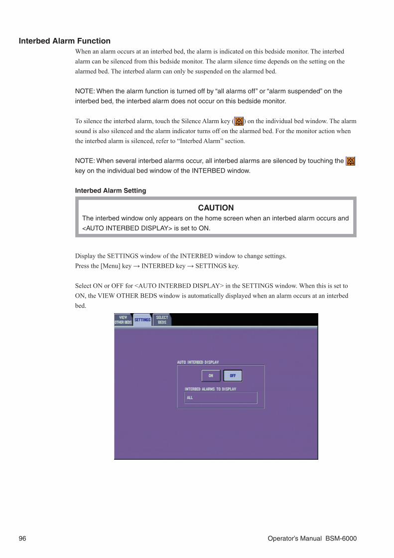
Interbed Alarm FunctionWhen an alarm occurs at an interbed bed, the alarm is indicated on this bedside monitor. The interbed alarm can be silenced from this bedside monitor. The alarm silence time depends on the setting on the alarmed bed. The interbed alarm can only be suspended on the alarmed bed.
NOTE: When the alarm function is turned off by “all alarms off” or “alarm suspended” on the
interbed bed, the interbed alarm does not occur on this bedside monitor.
To silence the interbed alarm, touch the Silence Alarm key ( ) on the individual bed window. The alarm sound is also silenced and the alarm indicator turns off on the alarmed bed. For the monitor action when the interbed alarm is silenced, refer to “Interbed Alarm” section.
NOTE: When several interbed alarms occur, all interbed alarms are silenced by touching the
key on the individual bed window of the INTERBED window.
Interbed Alarm Setting
CAUTIONThe interbed window only appears on the home screen when an interbed alarm occurs and
<AUTO INTERBED DISPLAY> is set to ON.
Display the SETTINGS window of the INTERBED window to change settings.Press the [Menu] key → INTERBED key → SETTINGS key.
Select ON or OFF for <AUTO INTERBED DISPLAY> in the SETTINGS window. When this is set to ON, the VIEW OTHER BEDS window is automatically displayed when an alarm occurs at an interbed bed.
96 Operator’s Manual BSM-6000
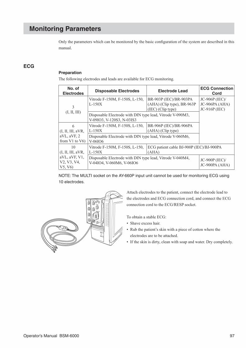
Monitoring Parameters
Only the parameters which can be monitored by the basic configuration of the system are described in this manual.
ECGPreparation
The following electrodes and leads are available for ECG monitoring.
No. of Electrodes
Disposable Electrodes Electrode LeadECG Connection
Cord
3(I, II, III)
Vitrode F-150M, F-150S, L-150, L-150X
BR-903P (IEC)/BR-903PA (AHA) (Clip type), BR-963P (IEC) (Clip type)
JC-906P (IEC)/JC-906PA (AHA)JC-916P (IEC)
Disposable Electrode with DIN type lead, Vitrode V-090M3, V-09IO3, V-120S3, N-03IS3
6(I, II, III, aVR, aVL, aVF, 2 from V1 to V6)
Vitrode F-150M, F-150S, L-150, L-150X
BR-906P (IEC)/BR-906PA (AHA) (Clip type)
Disposable Electrode with DIN type lead, Vitrode V-060M6, V-06IO6
10(I, II, III, aVR, aVL, aVF, V1, V2, V3, V4, V5, V6)
Vitrode F-150M, F-150S, L-150, L-150X
ECG patient cable BJ-900P (IEC)/BJ-900PA (AHA)
Disposable Electrode with DIN type lead, Vitrode V-040M4, V-04IO4, V-060M6, V-06IO6
JC-900P (IEC)/JC-900PA (AHA)
NOTE: The MULTI socket on the AY-660P input unit cannot be used for monitoring ECG using
10 electrodes.
Attach electrodes to the patient, connect the electrode lead to the electrodes and ECG connection cord, and connect the ECG connection cord to the ECG/RESP socket.
To obtain a stable ECG:• Shave excess hair.• Rub the patient’s skin with a piece of cotton where the
electrodes are to be attached.• If the skin is dirty, clean with soap and water. Dry completely.
Operator’s Manual BSM-6000 97

WARNINGAfter attaching the electrode to the patient and
connecting the cable to the monitor, check that
electrodes are attached to the patient and check
that the cable is connected to the monitor properly.
When the electrodes are removed from the patient,
do not touch the metal part of the electrode with
bare hands or let the metal part of the electrode
contact the metal part of the bed or any other
conductive parts. Failure to follow this warning may
cause electrical shock or injury to the patient by
discharged energy.
WARNINGWhen using a defibrillator together with the
monitor, use Ag/AgCl electrodes. Other types of
electrodes, stainless steel in particular, will
adversely affect the ECG waveform by slowing the
baseline recovery on the monitor and result in no
monitoring immediately following defibrillation.
WARNINGDo not use 12 lead ECG interpretation results and
measured values from the Mason-Likar
modification for diagnosis because the limb
electrode placement is not the same as the
standard 12 lead ECG. This may cause wrong
diagnosis since 12 lead ECG interpretation of this
monitor is based on the standard 12 lead ECG.
CAUTIONAt the start of ECG monitoring, check that the
dominant QRS is appropriate. Otherwise
arrhythmia monitoring may be inaccurate.
CAUTIONOnly use Nihon Kohden specified electrodes and
electrode leads. When other type of electrodes or
electrode leads are used, the “CHECK
ELECTRODES” message may be displayed and
ECG monitoring may stop.
CAUTION• When using the electrodes with DIN type lead,
use only Vitrode V or N electrodes. If other
electrodes are used, the electrode lead might not
be properly connected and ECG monitoring may
be unstable.
• Do not use electrodes of different metals. ECG
monitoring may be unstable if electrodes of
different metals are used.
CAUTIONWhen the “NOISE” or “CANNOT ANALYZE”
message is displayed, ECG data and alarm are
not reliable. Remove the cause by checking the
electrodes, electrode leads, patient’s body
movement, EMG and peripheral instruments
grounding. Also make sure that an electric blanket
is not used.
CAUTIONWhen the “CHECK ELECTRODES” message is
displayed, ECG is not monitored properly and the
ECG alarm does not function. Check the electrode,
electrode leads and connection cord, and if
necessary, replace with new ones.
98 Operator’s Manual BSM-6000

NOTE
• When a line isolation monitor is used, noise from the line isolation monitor may resemble
actual ECG waveforms on the bedside monitor and cause false heart rate alarms or no alarm
at all.
• Do not use the different types of the electrodes together. This might cause ECG monitoring to
become unstable.
When using 3 electrodes, one lead can be monitored. When using 6 electrodes, 8 leads can be monitored. When using 10 electrodes, up to 12 leads can be monitored and 12 lead ECG interpretation can be analyzed. For details on the 12 lead interpretation, refer to the “12 LEAD ANALYSIS Window” in “12 LEAD/12 LEAD ANALYSIS Windows” section.
Use with an Electrosurgical UnitFor use with an electrosurgical unit (ESU), this monitor has a circuit to protect the patient from skin burn and to reduce ESU interference on the ECG waveform. However, the effectiveness of this circuit depends on electrode position and monitor setup. With an ESU, pay attention to the following points.
WARNINGWhen the monitor is used with an electrosurgical unit (ESU), firmly attach the entire area of
the ESU return plate. Otherwise, the current from the ESU flows into the electrodes of the
monitor, causing electrical burn where the electrodes are attached. For details, refer to the
ESU manual.
CAUTIONWhen using the monitor with an ESU, locate the monitor and ESU appropriately and
ground instruments properly. Otherwise noise from the ESU may interfere with the ECG
and the heart rate and arrhythmia analysis may be incorrect.
• Arrangement Install the monitor as far from the ESU as possible. If possible, locate them on opposite sides of the
operating table.
• Power supply Noise from the ESU may interfere with the ECG signal through the AC power line. Supply power to the
monitor and ESU from different outlets located as far from each other as possible. Do the equipotential grounding properly.
Power supply and grounding for monitor
3 electrodes
Bedside monitorOperating table
ESU
Power supply and grounding for ESU
Operator’s Manual BSM-6000 99

• Measure with 3-electrode lead Use the minimum number of electrodes. Use new electrodes.• Minimize noise
1. Select an ECG lead where the active ECG electrodes are located as far from the incision as possible.
2. Position the + and – electrodes as close as possible.3. Select the leads where the angle (θ) between the active electrodes and the incision is as small as
possible.4. Set the electrosurgical return plate as close to the incision as possible.
Make small
IncisionReturn plate
As far as possible from electrode andas near as possible to incision.
• Set the following items on the OTHER page of the ECG window. FILTERS: MAXIMUM SYNC SOURCE: SpO2 or PRESS
• Monitor respiration by thermistor method or monitor CO2
Noise is superimposed on the waveform and the respiration rate cannot be monitored accurately in the impedance method. When monitoring respiration, turn respiration monitoring off or monitor the respiration by thermistor method or monitor CO2.
Monitoring Arrhythmia
The following arrhythmias are monitored.
Arrhythmia Name DescriptionASYSTOLE Longer than 3 to 10 seconds (selectable) with no QRS complex.VF Ventricular fibrillation longer than 4 seconds.
VTVentricular tachycardia. 3 to 9 (selectable*1) or more consecutive VPCs when heart rate exceeding the VT heart rate limit (16 to 300 beats/min selectable*1).
EXT TACHY*1 Extreme tachycardia exceeding the EXTREME TACHY limit.EXT BRADY*1 Extreme bradycardia dropping below the EXTREME BRADY limit.
V BRADY*1 Ventricular bradycardia. 3 or more consecutive VPCs when heart rate drops below the V BRADY heart rate limit (15 to 299 beats/min selectable).
VPC RUN
VPC short run. 3 to 8 (selectable) consecutive VPCs when heart rate exceeds the VPC RUN heart rate limit (16 to 300 beats/min selectable*1).orThe selected number*2 of consecutive VPCs when heart rate drops below the VT heart rate limit.
SV TACHY*1Supraventricular tachycardia. 3 to 9 (selectable) or more consecutive normal QRS of regular R-R interval when heart rate exceeding the SV TACHY heart rate limit (16 to 300 beats/min selectable).
TACHYCARDIA Heart rate above the upper heart rate limit.BRADYCARDIA Heart rate below the lower heart rate limit.PAUSE*1 1 to 3 seconds (selectable) with no QRS.V RHYTHM*1 Ventricular rhythm. 3 or more consecutive VPCs.COUPLET VPC couplet (paired VPCs). 2 consecutive VPCs.
100 Operator’s Manual BSM-6000

Arrhythmia Name Description
EARLY VPCEarly VPC including R-on-T type. VPC with a time interval from the preceding normal QRS complex of less than approximately one-third of the normal R-R interval, at heart rate dropping below 120*3 beats/min.
MULTIFORM*1 Two different shaped VPCs within the last 3 minutes.
BIGEMINY Ventricular bigeminy. 3 or more consecutive pairs of VPC and normal QRS. A dominant rhythm of N-V-N-V-N-V (N = normal beat, V = ventricular beat)
TRIGEMINY*1 Ventricular trigeminy. A dominant rhythm of N-N-V-N-N-V.
FREQ VPC Frequent VPCs. VPC rate (VPCs/min) reaching or exceeding the preset limit of 1 to 99 VPCs/min (selectable).
VPC Ventricular premature contraction.AF*4 Atrial fibrillation longer than 2 minutes.IRREGULAR RR*1 Consistently irregular R-R intervals.PROLONGED RR*1 R-R interval 1.75 times longer than the dominant R-R interval.NO PACER PULSE*1*5 No QRS and pacing pulse within the bradycardia limit. Oversensing.PACER NON-CAPTURE*1*5
No QRS from the preceding pacing pulse for the preset time interval (40 to 480 ms selectable). Non-capture.
*1 These become available when “EXTENDED” is selected for <ARRHYTHMIA TYPE> on the SYSTEM SETUP window.
*2 This number is set in the VT alarm setting.*3 120 beats/min when <QRS DETECTION TYPE> is set to ADULT, 150 beats/min when <QRS
DETECTION TYPE> is set to CHILD or NEONATE.*4 Not available for BSM-6000K series. Available only when <ARRHYTHMIA TYPE> on the ECG
page of the SYSTEM SETUP window is set to EXTENDED, and <AF DETECTION> on the ECG page of the SYSTEM SETUP window is set to On. For the SYSTEM SETUP window settings, refer to the Administrator’s Guide.
*5 Available only when pacing detection is set to On.
WARNINGIt is not possible to obtain 100% accurate detection of every arrhythmia.
WARNINGDo not use AF detection for children or neonates. The monitor might not correctly detect AF
in children or neonates.
WARNINGThe monitor requires a minimum of 2 minutes of continuous analysis before AF can be
detected. Detection may take up to 2.5 minutes.
To monitor arrhythmia, <ARRHYTHMIA ANALYSIS> on the ARRHYTH ANALYSIS window must be set to ON.
WARNINGFor arrhythmia monitoring, set <ARRHYTHMIA ANALYSIS> on the ECG window to ON.
Otherwise, there is no sound or indication for arrhythmia alarms (except for ASYSTOLE).
Operator’s Manual BSM-6000 101

CAUTIONIf there is any doubt about the arrhythmia analysis, make the monitor relearn the patient’s
ECG and check that the dominant QRS is appropriate. Otherwise, an important arrhythmia
may be overlooked.
Changing Arrhythmia Monitoring SettingsTurning Arrhythmia Analysis On or Off
Select ON or OFF in <ARRHYTHMIA ANALYSIS> box.
Selecting Arrhythmia Analysis Leads
Select SINGLE or MULTIPLE in <ARRHYTHMIA ANALYSIS METHOD> box to select the number of analyzing leads.SINGLE: The lead selected for the first trace is analyzed.MULTIPLE: The leads selected for the first and second traces are analyzed.
Selecting the Patient Type for QRS Detection
CAUTIONAt the start of ECG monitoring, check that the correct patient type is set for <QRS
DETECTION TYPE> on the ARRHYTH ANALYSIS page of the ECG window. If an
inappropriate patient type is set, heart rate cannot be counted accurately and noise or P
waves may be counted as QRS and cardiac arrest may be overlooked.
The patient type for QRS detection is the same as the patient type selected on the ADMIT DISCHARGE window. If necessary, you can change the type for QRS detection. Select the monitoring patient type in the QRS DETECTION TYPE box. The selected patient type is displayed on the home screen. This setting returns to the master setting on the ARRHYTH page of the MASTER window when 30 minutes elapse after monitor power off.
102 Operator’s Manual BSM-6000

The QRS settings depend to the patient type.
ItemsQRS DETECTION TYPE Setting
ADULT CHILD NEONATEDetect narrow QRS Not available Not available Available
QRS detection sensitivity Automatic sensitivity Same as the <SENSITIVITY> setting Automatic sensitivity
Default setting of ISO point R – 80 ms R – 56 msDefault setting of J point R + 48 ms Cannot be setDefault setting of ST point J + 60 ms R + 60 ms
Learning the ECG Waveform for Arrhythmia Detection
To learn ECG for arrhythmia detection, touch the LEARN key on the MAIN or ARRHYTH ANALYSIS page. The Dominant QRS is updated.
Checking the Dominant QRS
The dominant QRS and ECG of the selected first trace is displayed on the ARRHYTH ANALYSIS page.The monitor detects QRS of the monitoring ECG and classifies them into templates. The monitor selects the most typical QRS, called dominant QRS, and uses it for analyzing arrhythmia. Whenever ECG is learned or relearned, the dominant QRS is refreshed.
The ECG on ARRHYTH ANALYSIS window are annotated by the following QRS classification.
QRS Annotation DescriptionN Normal QRS complexV Ventricular premature contractionP Paced QRS? Impossible to classify or during learning– Noise
If there is any doubt about the arrhythmia analysis, make the monitor relearn the patient’s ECG and check the dominant QRS.
NOTE: The ECG waveform on the ECG window is delayed 5 seconds.
Operator’s Manual BSM-6000 103

Changing ECG Settings
Change settings on the ECG window. The following settings can be changed for ECG monitoring.• ECG measurement on or off• Monitoring lead and lead name• ECG sensitivity• Number of ECG traces on the home screen• Learn ECG. Refer to the “Monitoring Arrhythmia” section.• Heart rate, arrhythmia and ST alarm limits and setting• Arrhythmia analysis on or off. Refer to the “Monitoring Arrhythmia” section.• Arrhythmia analysis lead. Refer to the “Monitoring Arrhythmia” section.• Check dominant QRS. Refer to the “Monitoring Arrhythmia” section.• ST level settings• Pacing setting• Number of electrodes• Auto lead change on or off when electrode is detached• Heart rate display mode• Filter mode• Hum filter on or off• Sync source• Sync sound pitch• Pulse rate display on or off• QRS detection type
The following items can be set on the SYSTEM SETUP window.• ECG electrode lead type (IEC or AHA)• Heart rate sync sound pitch• ECG display color• Arrhythmia type (standard or extended)• Cascade ECG waveform
The ST level unit (mV or mm) can be set on the SYSTEM CONFIGURATION screen.
The scale of the heart rate and ST level trendgraphs on the home screen are the same scale as the trendgraphs of the Review window.
The ECG sweep speed is the speed set for <SWEEP SPEED> on the WAVES page of the DISPLAY window.
104 Operator’s Manual BSM-6000

On the MAIN Page<SENSITIVITY>: Select sensitivity for all monitoring ECG waves on the home screen.
<LEAD>: Select the lead for the selected trace on the home screen.
<ALARMS>HR/PR alarm limits: Set the upper and lower heart rate or pulse rate alarm limits.*1*2
VPC alarm limit: Set the upper VPC alarm limit.NOTE: VPC alarm limit can only be set
when <ARRHYTHMIA ANALYSIS> on the
ECG window is ON.
ST alarm limits: Set the upper and lower ST alarm limits of the first trace.
*1 On BSM-6000A series, if <CRISIS VITAL ALARM MANAGEMENT> on the SYSTEM CONFIGURATION screen is turned on and “ALARM PRIORITY” on the SYSTEM SETUP window is set to CRISIS, the alarm setting is set to the alarm master setting.
*2 On BSM-6000A series, if <ALARM CAP> on the SYSTEM CONFIGURATION screen is turned on, the alarm setting is affected by the “ALARM CAP” setting on the SYSTEM SETUP window.
On the ST ALARMS Page<ALARMS>: Set the upper and lower ST alarm limits for each lead individually or all leads together. Touch the ST-ALL key to set all the alarm limits together for all leads. ST-ALL is based on the current measurement value.
Operator’s Manual BSM-6000 105

On the ARRHYTH Page
WARNINGFor arrhythmia monitoring, set <ARRHYTHMIA ANALYSIS> on the ECG window to ON.
Otherwise, there is no sound or indication for arrhythmia alarms (except for ASYSTOLE).
CAUTIONWhen the alarm is turned OFF for an arrhythmia, there will be no alarm for that arrhythmia
type. There is no message or mark to indicate that a certain arrhythmia alarm is turned off.
Therefore, be careful when you turn off an arrhythmia alarm.
Turn the alarm for individual arrhythmias ON or OFF and set the threshold for some arrhythmias.
NOTE:
For BSM-6000A series bedside monitors:
• Items can be turned on or off but
thresholds are fixed and cannot be
changed. The thresholds are set by the
administrator on the MASTER window of
the SYSTEM SETUP window.
• Arrhythmia alarm whose priority is set
to CRISIS on the ALARM window of the
SYSTEM SETUP window cannot be set
to OFF.
When EXTENDED is selected for the <ARRHYTHMIA TYPE> on the ECG page of the PARAMETERS window in the SYSTEM SETUP window, touch the threshold to display the ARRHYTH window and adjust the setting.
106 Operator’s Manual BSM-6000

On the OTHER Page<FILTERS>: Select the filter type.DIAG: No filter. This mode is best for viewing the details of the waveform. It is similar to the real ECG. (0.05 to 150 Hz)MONITOR: Low-cut and high-cut filter. (0.3 to 40 Hz)MAXIMUM: Baseline drift-free, hum (AC) and high-cut filter. Appropriate when there is noise from AC or ESU. (1 to 18 Hz)
NOTE:
• When performing defibrillation, set the
<FILTERS> to MONITOR or MAXIMUM.
The waveform recovery may become
slow due to electrode polarization when
DIAG is set.
• When sending data using a ZS-900P transmitter, the waveform data is limited to the following
frequency response depending on the filter setting. For the frequency response of the BSM-
6000 series bedside monitor, refer to the “Specifications” section.
DIAG mode: 0.05 to 60 Hz
MONITOR/MAXIMUM mode: 0.3 to 60 Hz
The waveform may be distorted or the “CHECK ELECTRODES” message may be displayed
on the receiving monitor when the waveform amplitude exceeds ± 5 mV.
<HUM FILTER>: Turn the hum filter on or off.
<HR DISPLAY MODE>: Select the mode for updating the heart rate.AVERAGE: The heart rate is calculated by a moving average. The monitor detects 12 consecutive beats including VPC, averages the R-R intervals of the latest 12 beats and uses this average to calculate the current heart rate. When a new beat is detected, the heart rate is recalculated using the latest 12 beats. The heart rate display is updated every 3 seconds.INSTANT: The heart rate is calculated every beat. The heart rate display is updated every 3 seconds.
<PACING>
WARNINGTurn the pacing pulse detection* to ON when monitoring a pacemaker patient. Otherwise
the pacemaker pulse is not rejected. However, even when the pacing pulse detection is set
to ON, the pacemaker pulse might not be rejected. When the pacemaker pulse is not
rejected, the pacemaker pulse is detected as QRS and false heart rate may be indicated or
critical arrhythmia such as asystole may be overlooked. Keep pacemaker patients under
close observation.
* For the pacemaker pulse rejection capability of BSM-6000 series bedside monitor, refer to the “Specifications - ECG” section.
Operator’s Manual BSM-6000 107

WARNINGEven when the pacing pulse detection is set to ON, the pacemaker pulse can be
overlooked or detected as QRS. You cannot confirm the pacemaker operation only from the
detected pacemaker pulse.
NOTE: When you monitor a premature baby or infant and the monitor miscounts the narrow
width QRS, set this to OFF.
<DETECT>: Select ON when detecting pacing pulse.
<MARK>: Select ON to display pacing mark on the ECG waveform.The pacing mark display position (above wave or overlap wave) on the ECG waveform can be selected on the PARAMETERS window of the SYSTEM SETUP window.
<AUTO LEAD CHANGE>: When monitoring with 6 or 10 electrodes and when this item is set to ON, the lead for the first trace on the home screen can be automatically changed to a stable lead when there is an electrode detachment or the “CHECK ELECTRODES” message is displayed for more than 5 seconds on the screen.
<NUMBER OF ELECTRODES>: Select the type and number of electrodes.STANDARD: Any electrodes other than DIN type. The number of electrodes (3, 6 or 10) is automatically recognized by the monitor.INDIV 6: Monitoring with 3 or 6 DIN type electrodes.INDIV 10: Monitoring with more than 10 DIN type electrodes. The RF/RL electrode must be attached.
<ECG MEASUREMENT>: Select ON when monitoring ECG.
CAUTIONWhen monitoring SpO2 only, detection of arrhythmia and asystole is not available and
arrhythmia alarms such as ASYSTOLE, VF or VT are not available. If the patient requires
ECG monitoring, monitor the ECG.
CAUTIONWhen monitoring SpO2 only (without ECG monitoring), turn on both the upper and lower
limit alarms for PR and SpO2. If the patient’s pulse is not detected during asystole or other
condition, a “CANNOT DETECT PULSE” or “CHECK PROBE” alarm occurs instead of an
SpO2 limit alarm. Furthermore, if the patient has no pulse, noise from probe movement
could be misjudged as a pulse and cause an incorrect PR or SpO2 value to be displayed.
NOTE:
• The <ECG MEASUREMENT> setting cannot be changed to OFF while ECG is monitored.
• Even when the setting is set to OFF, the setting automatically changes to ON when ECG
measurement is started. If the measured value and waveform are not displayed on the home
screen within 10 seconds, change the setting to ON manually.
• After setting <ECG MEASUREMENT> to ON, check that the ECG waveform is displayed on
the home screen.
108 Operator’s Manual BSM-6000

<SYNC SOURCE>: Select the sync sound source from ECG (heart rate), arterial blood pressure (IBP) and SpO2.
NOTE:
• When heart rate is unstable because of an ESU, select SpO2 or PRESS.
• When the SpO2 connection cord is disconnected or the SpO2 probe is detached and an alarm
occurs, the sync source changes to ECG (HR). The sync source returns to SpO2 when the
SpO2 is measured again.
• The SpO2-2 cannot be set to the sync sound source.
<PR DISPLAY>: Select the pulse rate display on or off. This setting is only available when <SYNC SOURCE> is set to ECG.
<SYNC PITCH>: Select the sync sound pitch.FIXED: The pitch is fixed to the pitch selected on the SYSTEM SETUP window.PRESS: The pitch is high when the BP value is above 120 mmHg. The pitch is low when the BP value is below 20 mmHg. The pitch changes in 20 steps from high to low for each 5 mmHg change between 120 and 20 mmHg BP value. The BP value of the highest priority arterial blood pressure is used.SpO2: The pitch changes in 20 steps from high to low for each 1%SpO2 change between 100%SpO2 and 81%SpO2 in SpO2 value of SpO2 connected to the SpO2 socket.SpO2-2: The pitch changes in 20 steps from high to low for each 1%SpO2 change between 100%SpO2 and 81%SpO2 in SpO2 value of SpO2-2 connected to the MULTI socket. SpO2-2 is only available for the AY-661P, AY-663P, AY-671P or AY-673P input unit or the BSM-1763 or BSM-1773 bedside monitor.
On the ECG 2/3 WAVES Page<NO. ECG WAVES>: Select 1, 2, or 3 to change the number of ECG waveforms.
<ECG2 SENSITIVITY>: Select sensitivity for the second trace on the home screen.
<ECG3 SENSITIVITY>: Select sensitivity for the third trace on the home screen.
<ECG2 LEAD>: Select the lead for the second trace on the home screen.
<ECG3 LEAD>: Select the lead for the third trace on the home screen.
Operator’s Manual BSM-6000 109

On the V-LEADS PageWhen monitoring with 6 electrodes, you can assign the leads for Va and Vb. After assigning the Va and Vb leads, select the monitoring lead.
On the ST POINT PageSet the ISO (Isoelectric) point, J point and ST point for ST level measurement.
NOTE: Although the ST algorithm has been tested for accuracy of the ST analysis result, the
significance of the ST level changes need to be determined only by a physician.
Select the lead(s) from the LEAD box to be displayed on the ST POINT page. The QRS wave(s) of the selected lead(s) appears on the page.
Touch the vertical cursor left or right for each point. Use the or key to adjust the vertical cursor left or right for each point.
To change the ST point, touch the ST POINT key.
To register the ST level measurement condition settings, touch the SET key.
110 Operator’s Manual BSM-6000

Respiration
WARNINGThe bioelectric impedance measurement sensor of a minute ventilation rate-adaptive
implantable pacemaker may be affected by cardiac monitoring and diagnostic equipment
which is connected to the same patient. If this occurs, the pacemaker may pace at its
maximum rate and give incorrect data to the monitor or diagnostic equipment. In this case,
set the IMPEDANCE MEASUREMENT on the RESP/CO2 window to OFF on the bedside
monitor. For a patient that requires the respiration monitoring, measure the respiration by
thermistor method.
Preparation
Impedance method: Attach electrodes to the patient and connect the ECG connection cord to the ECG/RESP socket. Attach R and F (RA and LL) or R and L (RA and LA) with the lungs between the electrodes.
Thermistor method: Attach the respiration pickup to the patient and connect the respiration pickup to the MULTI socket.
NOTE: The MULTI socket on the AY-660P input unit
cannot be used for monitoring respiration in thermistor
method.
The following respiration pickups are available.TR-900P* respiration pickup for noseTR-910P respiration pickup for airway. YG-001P airway adapter is required.* This part has not been checked for compliance with the MDD (Medical
Device Directive). For EC member countries, Nihon Kohden recommends the use of parts that comply with MDD.
NOTE: Increase in the temperature of the inspired
air during monitoring in thermistor method causes
decrease in the temperature difference between
inspiration and expiration, and the amplitude of the
respiration waveform becomes small. When the
inspiration temperature increases higher than the
expiration temperature, the phases of expiration and
inspiration may be reversed.
R/RA
F/LL
L/LA
Standard R-F/RA-LL
Electrode lead and position
R/RA L/LA
F/LL
R-L/RA-LA
R/RA
F/LL
L/LA
R-F/RA-LL with higher F/LL position
When connecting the TR-900P respiration pickup
TR-900P TR-910P
YG-001P
Operator’s Manual BSM-6000 111

Changing Respiration Settings
Change settings on the RESP/CO2 window. The following settings can be changed for respiration monitoring.
For impedance method• Changing monitoring lead• Turning respiration monitoring on or off• Displaying respiration rate as second parameter• Respiration sensitivity• Respiration rate and apnea alarm limits• Respiration waveform sweep speed
For thermistor method• Respiration sensitivity• Respiration rate and apnea alarm limits• Respiration waveform sweep speed
The noise reduction for impedance respiration monitoring can be turned on or off and respiration data display color can be set on the SYSTEM SETUP window.
The scale of the respiration rate trendgraph on the home screen is the same scale as the trendgraph of the Review window.
On the MAIN Page<IMPEDANCE RESP LEAD>: Select the monitoring lead.
<SENSITIVITY>: Select sensitivity for respiration waveform on the home screen and recording paper.
<ALARMS>:RR alarm limits: Set the upper and lower respiration rate alarm limits.*1*2
APNEA alarm limit: Set the upper apnea alarm limit.*1*2
CO2 alarm limits: Set the upper and lower CO2 alarm limits.*1*2
*1 On BSM-6000A series, if <CRISIS VITAL ALARM MANAGEMENT> on the SYSTEM CONFIGURATION screen is turned on and “ALARM
PRIORITY” on the SYSTEM SETUP window is set to CRISIS, the alarm setting is set to the alarm master setting.
*2 On BSM-6000A series, if <ALARM CAP> on the SYSTEM CONFIGURATION screen is turned on, the alarm setting is affected by the “ALARM CAP” setting on the SYSTEM SETUP window.
112 Operator’s Manual BSM-6000

On the OTHER Page<IMPEDANCE MEASUREMENT>: Select respiration monitoring in impedance method on or off.
<RESP/CO2 SWEEP SPEED>: Select the respiration waveform sweep speed.
<DISPLAY IMP-RR AS SECOND PARAMETER>: Respiration rate by impedance method can be displayed as a second respiration rate parameter together with the first respiration rate parameter. Select ON to display two measured values of respiration rate.
Operator’s Manual BSM-6000 113

CO2 CO2 monitoring by the mainstream method is performed by connecting the TG-900P, TG-920P, TG-950P, TG-970P or TG-980P CO2 sensor kit to the patient’s respiration circuit or directly to the patient and connect the CO2 sensor kit to the MULTI socket or PRESS CO2 socket on the unit. When monitoring with the TG-950P, TG-970P or TG-980P CO2 sensor kit, FiCO2 is also monitored.
CO2 by the sidestream method can be monitored when the optional AG-400R CO2 unit, Oridion portable bedside monitor Microcap® or Covidien Microstream®
Micropod™ capnography module is connected to the monitor. For details on the sidestream method, refer to the AG-400R CO2 unit, Oridion portable bedside monitor Microcap® or Covidien Microstream®
Micropod™ capnography module manual.
NOTE:
• TG-950P CO2 sensor kit and AG-400R CO2 unit are not available for BSM-6000A series.
• Oridion Microcap® portable bedside monitor is not available for BSM-6000K series.
Semi-quantitative method using the TG-900P or TG-920P CO2 sensor kitMeasurements are based on the assumption of no CO2 gas in the inspiration. The CO2 concentration in the respiration is calculated by taking the CO2 concentration in the inspiration as 0 mmHg (0 kPa).
Quantitative method using the TG-950P, TG-970P or TG-980P CO2 sensor kitThe CO2 partial pressure in both inspiration and expiration is measured.
WARNINGThe TG-970P and TG-980P CO2 sensor kits
cannot correctly measure the ETCO2 value and
respiration rate during high frequency oscillation
(HFO). Do not diagnose the patient from the
ETCO2 value and respiration rate.
CAUTIONSupply adequate oxygen when measuring CO2
partial pressure of a patient connected to a
Jackson Rees, Mapleson D or any other
respiration circuit where CO2 gas may be present
during inspiration. The semi-quantitative method
measures CO2 partial pressure based on the
assumption of no CO2 gas in the inspired air; it
assumes CO2 partial pressure 0 mmHg (0 kPa) in
the inspiration of every respiration. If the inspired
air contains CO2 gas, the measured CO2 value
may be lower than the actual value.
CAUTIONWith the TG-950P, TG-970P or TG-980P CO2
sensor kit, measured value may be incorrect when
the operating temperature changes greatly. In this
case, wait for about 30 minutes to acquire correct
measurement.
CAUTIONWhen measuring CO2 partial pressure of a patient
with an oxygen mask, set the oxygen supply to
5 L/min or more. If CO2 gas remains in the oxygen
mask and mixes with the inspired air, the
measured value may be lower than the actual
value.
CAUTIONThe TG-900P and TG-920P CO2 sensor kits do not
adjust the measurement value to compensate for
different atmospheric pressure. Be careful when
reading the value when using the CO2 sensor kit at
high altitudes because the measurement value
may be inaccurate.
* The measurement value drops 0.13 kPa (1 mmHg) for 5.33 kPa (40 mmHg) CO2 gas when an atmospheric pressure drops 3.3 kPa.
114 Operator’s Manual BSM-6000

NOTE:
• Only one MULTI socket can be used for monitoring CO2. The sidestream and mainstream
methods cannot be monitored at the same time.
• When the AG-920R, GF-110PA or GF-210R multigas unit or GF-120PA or GF-220R multigas/
flow unit is connected to the monitor, turn off the AG-920R multigas unit power or disconnect
the multi-link cable of the GF-110PA or GF-210R multigas unit or GF-120PA or GF-220R
multigas/flow unit from the monitor while monitoring CO2 by mainstream method. The CO2
alarm from mainstream method cannot be indicated when the multigas unit or multigas/flow
unit is turned on. (GF-120PA or GF-220R multigas/flow unit is not available for BSM-6000A
series.)
• When using N2O anesthetic gas (nitrous oxide), set the gas composition on the GAS COMP window.
Preparation
Connect the CO2 sensor kit to the MULTI socket on the unit and connect the airway adapter to the CO2 sensor.
Types of CO2 Sensor Kits
Model Method AttachmentTG-900P Semi-quantitative Used on an intubated patient
TG-920P Semi-quantitative Attach to the patient nose or used on an intubated patient
TG-950P* Quantitative Used on an intubated patient
TG-970P, TG-980P Quantitative
Used on an intubated patient with YG-211T/213T/214TUsed on a non-intubated patient with YG-232T/242T/272T/282T
The CO2 sensor kit requires an airway adapter, nasal adapter or cap-ONE mask.
CO2 sensor kit Airway adapter/Nasal adapter WeightDead space
volumeSupply Code
TG-900P YG-101T airway adapter 10 kg or more 5 mL R801
TG-920P
YG-111T airway adapter 7 kg or more 4 mL R804YG-120T nasal adapter
10 kg or more 1.2 mLV921
YG-121T nasal adapter V922YG-122T nasal adapter V923
TG-950P*YG-201T* airway adapter for adult 10 kg or more 5 mL R802YG-202T* airway adapter for child 3 to 10 kg 2 mL R803
TG-970P, TG-980P
YG-211T airway adapter 7 kg or more 4 mL R805YG-213T/214T airway adapter for neonate and child
YG-213T: 2 to 7 kg 0.5 mL R806YG-214T: 2.5 to 7 kg 1.8 mL R807
YG-232T/242T cap-ONE mask for pediatric and infant
YG-232T: 20 to 40 kg 3.5 mL V933YG-242T: 7 to 20 kg 2.5 mL V935
YG-272T/282T cap-ONE mask for adultYG-272T: 30 kg or more 7 mL V938AYG-282T: 40 kg or more 10 mL V938C
* TG-950P CO2 sensor kit, YG-201T and YG-202T airway adapters are not available for BSM-6000A series.
Operator’s Manual BSM-6000 115

WARNINGWhen using the airway adapter or nasal adapter
on a patient with low ventilatory volume, the CO2
may mix in the inspiration due to the airway
adapter’s dead space, resulting in inaccurate
measured values or difficulty in detecting apnea.
Perform ventilation taking into consideration the
dead space of the adapters.
CAUTIONSelect the airway adapter or nasal adapter taking
into consideration the patient weight and
ventilation volume. If an inappropriate airway
adapter or nasal adapter is used, the resistance in
the respiration circuit increases and it causes
incorrect measurement value.
CAUTIONWhen the “CHANGE ADAPTER” or “SENSOR
ERROR” message is displayed, check the CO2
sensor kit and replace it if necessary. CO2 cannot
be monitored while the message is displayed.
CAUTIONThe CO2 data may be inaccurate when monitoring
a patient with an extremely high respiration rate or
irregular respiration. Read the measured values
carefully.
CAUTIONWhen monitoring CO2, make sure that the gas
composition is entered. Otherwise the
measurement result may be inaccurate.
CAUTIONWhen using an anesthetic instrument with a
volatile anesthetic agent, the CO2 measurement
may be inaccurate.
NOTE: The measurement may be inaccurate when monitored in the following conditions. Read
the measured values carefully.
• When used in environments with high concentration nitrous oxide gas.
• When used in environments with sudden temperature changes.
• When used in environments with severe humidity.
116 Operator’s Manual BSM-6000

NOTE: For intubated patients, connect the CO2 sensor as in the following example so that the
sensor does not touch the patient.
Connection Example
For intubated patients For non-intubated patients
TG-900P/TG-950P/TG-970P/TG-980P
Straight type tracheal tube Elbow type
tracheal tube
TG-920P
YG-111T airway adapter
TG-920P
YG-121T nasal adapter
TG-970P/TG-980PYG-232T/242T cap-ONE mask
Using the TG-920P CO2 Sensor Kit
WARNINGThe only oxygen cannula that can be used with
YG-122T is manufactured by HUDSON RCI®. Do
not use any other oxygen cannula. Other oxygen
cannulas cannot be attached and oxygen cannot
be delivered to the patient through the nostrils.
WARNINGCheck that the oxygen cannula tube is not bent,
broken, or blocked by the nasal tube. If the ends of
the oxygen cannula tube turn too far up or down, it
causes insufficient O2 supply or the CO2 value may
be incorrect.
WARNING• When you use YG-122T together with an oxygen
cannula, check that the oxygen cannula is
correctly attached on the patient by referring to
other parameters and by observing the patient
periodically.
• If arterial oxygen saturation does not increase,
immediately stop using the oxygen cannula with
the CO2 sensor kit and select another way to
supply oxygen.
CAUTIONWhen using the YG-121T/YG-122T nasal adapter
on a patient with bleeding disorder, poor general
medical condition or malnutrition, observe the
patient condition all the time. The mouth guide
touches the mouth and may cause pressure sores.
Operator’s Manual BSM-6000 117

Performing CalibrationWhen using the TG-950P, TG-970P or TG-980P CO2 sensor kit, perform zero calibration in the following conditions before connecting the CO2 sensor to the respiration circuit.• When the airway adapter is replaced with a new one.• When a different type of airway adapter is used.• When the operating temperature changes.• When the measurement room is changed.• Whenever necessary.
On the ZERO CAL PageZero calibration can be performed in two ways: calibration with air and calibration with N2 gas. Both methods are performed on the RESP/CO2 window.• Calibration with air
1. Touch the AIR CAL key.2. Expose the airway adapter to air.3. Touch the YES key. The CO2 sensor is
calibrated with about 0.2 mmHg (0.03 kPa) CO2 in the air.
• Calibration with N2 gas1. Touch the N2 CAL key.2. Flow N2 gas into the airway adapter.3. Touch the YES key. The CO2 sensor is
calibrated.
Changing CO2 Settings
Change the settings on the RESP/CO2 window. The following settings can be changed for CO2 monitoring.• Scale• Respiration rate, apnea and inspired CO2 alarm settings• Inspiration composition• CO2 waveform sweep speed• Duration for holding ETCO2 maximum value
The CO2 unit can be set to mmHg or kPa on the SYSTEM CONFIGURATION screen.
The CO2 data display color and CO2 waveform fill in or not can be set on the SYSTEM SETUP window.
118 Operator’s Manual BSM-6000

On the SCALE PageSelect the scale by touching the desired scale key. You can adjust the scale using the scale slider.
On the MAIN Page<ALARMS>RR alarm limits: Set the upper and lower respiration rate alarm limits.*1*2
APNEA alarm limit: Set the upper apnea alarm limit.*1*2
CO2(E) alarm limits: Set the upper and lower expired CO2 alarm limits.*1*2
CO2(I) alarm limits: Set the upper inspired CO2
alarm limits when monitoring CO2 with TG-950P, TG-970P or TG-980P CO2 sensor kit or by sidestream method.
*1 On BSM-6000A series, if <CRISIS VITAL ALARM MANAGEMENT> on the SYSTEM CONFIGURATION screen is turned on and “ALARM PRIORITY” on the SYSTEM SETUP window is set to CRISIS, the alarm setting is set to the alarm master setting.
*2 On BSM-6000A series, if <ALARM CAP> on the SYSTEM CONFIGURATION screen is turned on, the alarm setting is affected by the “ALARM CAP” setting on the SYSTEM SETUP window.
Operator’s Manual BSM-6000 119

On the GAS COMP Page<GAS COMPOSITION>: When using anesthetic gas or a respirator, set the inspiration composition.
This setting is not required when monitoring CO2 by sidestream method.
CAUTIONWhen monitoring CO2, make sure that the gas
composition is entered. Otherwise the
measurement result may be inaccurate.
CAUTIONWhen using an anesthetic instrument with a
volatile anesthetic agent, the CO2 measurement
may be inaccurate.
When N2O is mixed in the inspiration or when a high concentration of oxygen is inspired, sensitivity of CO2 absorbing infrared ray is affected, and as a result measurements cannot be performed correctly. When using anesthetic gas or a respirator, set the inspiration composition. The monitor corrects the CO2 concentration automatically according to the setting.
On the OTHER Page<RESP/CO2 SWEEP SPEED>: Select the CO2 waveform sweep speed.
<ETCO2 MAX HOLD>: Select the time for holding the maximum ETCO2 value. This setting is effective only when using the TG-950P* TG-970P or TG-980P CO2 sensor kit. When using the TG-900P or TG-920P CO2 sensor kit, this item is automatically set to OFF.10 sec: The maximum value for latest
10 seconds20 sec: The maximum value for latest
20 secondsOFF: The maximum value is updated each
breath.* This function is not available in some
versions.
120 Operator’s Manual BSM-6000

Inspection of Measuring Accuracy
The inspection of measuring accuracy must be performed by the qualified service personnel.
CAUTIONFollow the CAUTION label on the CO2 gas cylinder.
Use with Volatile Anesthetic Agents
CAUTIONWhen using an anesthetic instrument with a volatile anesthetic agent, the CO2 measurement
may be inaccurate.
Volatile anesthetic agents affect the CO2 value. Be aware of this when using volatile anesthetic agent.Example: At 1 atmospheric pressure and gas mixtures of 5% CO2 (5.1 kPa (38 mmHg)) and balance N2,
dry gas
Anesthetic Gas ConcentrationDifference
TG-900P TG-920P TG-950P TG-970P, TG-980P
Halothane 4% +0.9 mmHg +0.12 kPa
+0.6 mmHg +0.08 kPa
+0.2 mmHg +0.03 kPa
+0.3 mmHg+0.04 kPa
Enflurane 5% +1.5 mmHg +0.20 kPa
+1.5 mmHg +0.20 kPa
+0.4 mmHg +0.05 kPa
+0.9 mmHg+0.12 kPa
Isoflurane 5% +1.8 mmHg +0.24 kPa
+1.7 mmHg +0.23 kPa
+0.8 mmHg +0.11 kPa
+1.7 mmHg+0.22 kPa
Sevoflurane 6% +2.8 mmHg +0.37 kPa
+2.7 mmHg +0.36 kPa
+1.3 mmHg +0.17 kPa
+2.1 mmHg+0.28 kPa
Desflurane24% +7.0 mmHg
+0.93 kPa+6.6 mmHg +0.88 kPa
+3.2 mmHg +0.43 kPa —
15% +6.6 mmHg +0.88 kPa
+5.4 mmHg +0.72 kPa — +2.9 mmHg
+0.39 kPa
Operator’s Manual BSM-6000 121

SpO2 with Nihon Kohden Probes (AY-660P/AY-661P/AY-663P/AY-671P/AY-673P/BSM-1763/BSM-1773)
WARNINGSpO2 measurement may be incorrect in the
following cases.
• When the patient’s carboxyhemoglobin or
methemoglobin increases abnormally.
• When dye is injected in the blood.
• When using an electrosurgical unit.
• During CPR.
• When measuring at a site with venous pulse.
• When there is body movement.
• When the pulse wave is small (insufficient
peripheral circulation).
WARNING• When using the TL-201T finger probe, do
not fasten the probe and cable to the finger
by wrapping with tape. This may cause burn,
congestion or pressure necrosis from poor blood
circulation.
• When using probes other than the TL-201T
finger probe, to avoid poor circulation, do
not wrap the tape too tight. Check the blood
circulation condition by observing the skin
color and congestion at the skin peripheral to
the probe attachment site. Even for short-term
monitoring, there may be burn or pressure
necrosis from poor blood circulation, especially
on neonates or low birth weight infants whose
skin is delicate. Accurate measurement cannot
be performed on a site with poor peripheral
circulation.
WARNINGCheck the circulation condition by observing the
skin color at the measurement site and pulse
waveform. Change the measurement site every 8
hours for disposable probes and every 4 hours for
reusable probes (every 8 hours for TL-630T3/
TL-631T3 probe). The skin temperature may
increase at the attached site by 2 or 3°C (4 or 5°F)
and cause a burn or pressure necrosis. When
using the probe on the following patients, take
extreme care and change the measurement site
more frequently according to symptoms and
degree.
• Patient with a fever
• Patient with peripheral circulation insufficiency
• Neonate or low birth weight infant with delicate
skin
WARNINGWhen monitoring SpO2 of a patient who is
receiving photodynamic therapy, the light from the
finger probe sensor may cause a burn.
Photodynamic therapy uses a photosensitizing
agent that has a side effect of photosensitivity.
The SpO2 probe manufactured by Nihon Kohden have two wavelengths with peaks in the range of 650 and 950 nm. The maximum light intensity is less than 5.5 mW.
WARNINGWhen not monitoring SpO2, disconnect the SpO2
connection cord from the input unit. Otherwise,
noise from the probe sensor may interfere and
incorrect data is displayed on the screen.
CAUTIONTurn off the power of mobile phones, small
wireless devices and other devices which produce
strong electromagnetic interference around a
patient (except for devices allowed by the hospital
administrator). Radio waves from devices such as
mobile phones or small wireless devices may be
mistaken as pulse waves and the displayed data
may be incorrect.
CAUTIONOnly use the specified probes. Otherwise, SpO2
cannot be monitored.
CAUTIONNormal external light does not affect monitoring
but strong light such as a surgical light or sunlight
may affect monitoring. If affected, cover the
measuring site with a blanket.
122 Operator’s Manual BSM-6000
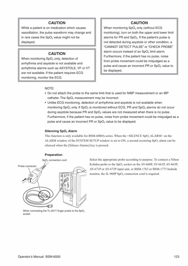
CAUTIONWhile a patient is on medication which causes
vasodilation, the pulse waveform may change and
in rare cases the SpO2 value might not be
displayed.
CAUTIONWhen monitoring SpO2 only (without ECG
monitoring), turn on both the upper and lower limit
alarms for PR and SpO2. If the patient’s pulse is
not detected during asystole or other condition, a
“CANNOT DETECT PULSE” or “CHECK PROBE”
alarm occurs instead of an SpO2 limit alarm.
Furthermore, if the patient has no pulse, noise
from probe movement could be misjudged as a
pulse and cause an incorrect PR or SpO2 value to
be displayed.
CAUTIONWhen monitoring SpO2 only, detection of
arrhythmia and asystole is not available and
arrhythmia alarms such as ASYSTOLE, VF or VT
are not available. If the patient requires ECG
monitoring, monitor the ECG.
NOTE:
• Do not attach the probe to the same limb that is used for NIBP measurement or an IBP
catheter. The SpO2 measurement may be incorrect.
• Unlike ECG monitoring, detection of arrhythmia and asystole is not available when
monitoring SpO2 only. If SpO2 is monitored without ECG, PR and SpO2 alarms do not occur
during asystole because PR and SpO2 values are not measured when there is no pulse.
Furthermore, if the patient has no pulse, noise from probe movement could be misjudged as a
pulse and cause an incorrect PR or SpO2 value to be displayed.
Silencing SpO2 Alarm
This function is only available for BSM-6000A series. When the <SILENCE SpO2 ALARM> on the ALARM window of the SYSTEM SETUP window is set to ON, a second occurring SpO2 alarm can be silenced when the [Silence Alarms] key is pressed.
Preparation
Select the appropriate probe according to purpose. To connect a Nihon Kohden probe to the SpO2 socket on the AY-660P, AY-661P, AY-663P, AY-671P or AY-673P input unit, or BSM-1763 or BSM-1773 bedside monitor, the JL-900P SpO2 connection cord is required.
When connecting the TL-201T finger probe to the SpO2
socket
SpO2 connection cord
Probe connector
Operator’s Manual BSM-6000 123

To monitor SpO2 at two sites (dual SpO2), connect a Nihon Kohden probe to the SpO2 socket and another probe to the MULTI socket on the AY-661P, AY-663P, AY-671P or AY-673P input unit, BSM-1763 or BSM-1773 bedside monitor, or AA-672P or AA-674P smart expansion unit. The MULTI socket on the AY-660P input unit cannot be used.
To connect a Nihon Kohden probe to the MULTI socket, the JL-500P1 or JL-500P2 SpO2 adapter is required.
When Monitoring Dual SpO2
CAUTIONWhen two probes are attached too close to each other,
the light from the probes interferes with each other and
SpO2 cannot be monitored properly. Make sure that there
is no light interference when attaching two probes.
Reusable Probes
Model Subject (Weight) Attachment SiteFinger Probe TL-201T Adults, children
(Weight 20 kg or more)Finger
Multi-site Probe TL-220T Adults, infants(Weight 3 kg or more)
Finger or toe
Neonates(Weight 3 kg or less)
Instep and sole
Finger Probe TL-630T3* Adults, children(Weight 50 kg or more)
Finger
Finger Probe TL-631T3 Adults, children(Weight 20 kg or more)
Finger or toe
Disposable Probes
Model Subject (Weight) Attachment SiteTL-260T* Children, neonates
(Weight 3 kg or more)Finger or toe(Attachment tape: type S)
Low birth weight infants(Weight 1 kg or less)
Instep and sole(Attachment tape: type S)
Neonates(Weight 3 kg or less)
Instep and sole(Attachment tape: type L)
TL-271T/271T3Cable lengthTL-271T: 80 cmTL-271T3: 160 cm
Adults(Weight 30 kg or more)
Finger or toe
TL-272T/272T3Cable lengthTL-272T: 80 cmTL-272T3: 160 cm
Children(Weight from 10 to 50 kg)
Finger or toe
TL-273T/273T3Cable lengthTL-273T: 80 cmTL-273T3: 160 cm
Adults(Weight 40 kg or more)
Finger or toe
Neonates(Weight 3 kg or less)
Instep
When connecting the TL-051S/052S probes to the SpO2 socket and MULTI socket to monitor dual SpO2
Sensor connector
SpO2 adapterLock cover
124 Operator’s Manual BSM-6000

Model Subject (Weight) Attachment SiteTL-274T/274T3Cable lengthTL-274T: 80 cmTL-274T3: 160 cm
Infants(Weight from 3 to 20 kg)
Finger or toe
TL-051S/052SCable lengthTL-051S: 80 cmTL-052S: 160 cm
Adults(Weight 50 kg or more)
Finger
Neonates(Weight 3 kg or less)
Instep and sole
TL-061S/062SCable lengthTL-061S: 80 cmTL-062S: 160 cm
Adults, children(Weight from 15 to 50 kg)
Finger
Children, infants(Weight from 3 to 15 kg)
Toe
* TL-260T multi-site Y probe and TL-630T3 finger probe are not available for BSM-6000A series.
CAUTIONWhen the probe is attached on an appropriate site
with sufficient circulation and an error message
about probe attachment repeatedly appears, the
probe may be deteriorated. Replace it with a new
one.
CAUTIONWhen a message indicates a faulty probe or faulty
SpO2 connection cord, stop monitoring and
replace the probe or SpO2 connection cord with a
new one.
CAUTIONIf the attachment site is dirty with blood or bodily
fluids, clean the attachment site before attaching
the probe. If there is nail polish on the attachment
site, remove the polish. Otherwise, the amount of
transmitted light decreases, and measured value
may be incorrect or measurement cannot be
performed.
NOTE:
• In order to maintain sufficient blood circulation, keep the measurement site warm by covering
with a blanket or something similar. Warming the site is effective, especially for a patient with a
small pulse amplitude.
• Connect the probe and SpO2 connection cord until you hear a stopper of the SpO2 connection
cord click.
Operator’s Manual BSM-6000 125
Changing SpO2 SettingsChange settings on the SpO2 window. The following settings can be changed for SpO2 monitoring.• Pulse waveform sensitivity• SpO2 and pulse rate alarm limits• Display pulse rate and/or PI in SpO2 numeric data area on the home screen• Display pulse rate to the left of the heart rate• Display SQI bar graph in SpO2 numeric data area on the home screen
The following settings can be changed on the SpO2-2 window for dual SpO2 monitoring.• Pulse waveform sensitivity• SpO2-2 and ∆SpO2 alarm limits• Display SpO2-2 pulse rate, PI and/or ∆SpO2 in SpO2-2 numeric data area on the home screen
The following settings are common settings for SpO2 and SpO2-2.• Sync source• Sync sound pitch• Response mode• Sensitivity mode (Available only when using the following units. The version can be confirmed on the
INFO page of the SYSTEM SETUP window.- BSM-6000 series software version 03-01 or later- AY-600P series input unit software version 03-01 or later, AY-600P series input unit SpO2 module
version 01-11 or later, or BSM-1763 or BSM-1773 bedside monitor- JL-500P1/P2 version 01-11 or later)
The SpO2 data display color can be set on the SYSTEM SETUP window.
The scale of the SpO2 trendgraph on the home screen is the same scale as the trendgraph of the Review window.
The SpO2 pulse waveform sweep speed is the speed set for <SWEEP SPEED> on the WAVES page of the DISPLAY window.
When monitoring dual SpO2, display the SpO2-2 page of the SpO2 window to change the SpO2-2 settings (AY-661P, AY-663P, AY-671P or AY-673P input unit or BSM-1763 or BSM-1773 bedside monitor only).
126 Operator’s Manual BSM-6000

On the MAIN PageSpO2 Tab
<SENSITIVITY>: Select sensitivity for pulse waveform on the home screen.
NOTE: The pulse wave amplitude varies
according to pulsation component ratio
of whole transmitted IR signal. When the
pulsation component ratio is 1%, the pulse
wave amplitude becomes about 10 mm at
×1 setting on the display.
<ALARMS>SpO2 alarm limits: Set the upper and lower SpO2 alarm limits.*1*2
HR/PR alarm limits: Set the upper and lower heart rate or pulse rate alarm limits.*1*2
*1 On BSM-6000A series, if <CRISIS VITAL ALARM MANAGEMENT> on the SYSTEM CONFIGURATION screen is turned on and “ALARM PRIORITY” on the SYSTEM SETUP window is set to CRISIS, the alarm setting is set to the alarm master setting.
*2 On BSM-6000A series, if <ALARM CAP> on the SYSTEM CONFIGURATION screen is turned on, the alarm setting is affected by the “ALARM CAP” setting on the SYSTEM SETUP window.
PI (Pulse-amplitude Index)
The Pulse-amplitude Index indicates the percentage of pulsatile signal in the entire transmitted IR signal. This index may be affected by an artifact.
SpO2-2 Tab
<SENSITIVITY>: Select sensitivity for SpO2-2 pulse waveform on the home screen.
NOTE: The pulse wave amplitude varies
according to pulsation component ratio
of whole transmitted IR signal. When the
pulsation component ratio is 1%, the pulse
wave amplitude becomes about 10 mm at
×1 setting on the display.
<ALARMS>SpO2-2 alarm limits: Set the upper and lower SpO2-2 alarm limits.*1*2
ΔSpO2 alarm limit: Set the upper ΔSpO2 alarm limit.
*1 On BSM-6000A series, if <CRISIS VITAL ALARM MANAGEMENT> on the SYSTEM CONFIGURATION screen is turned on and “ALARM PRIORITY” on the SYSTEM SETUP window is set to CRISIS, the alarm setting is set to the alarm master setting.
*2 On BSM-6000A series, if <ALARM CAP> on the SYSTEM CONFIGURATION screen is turned on, the alarm setting is affected by the “ALARM CAP” setting on the SYSTEM SETUP window.
Operator’s Manual BSM-6000 127

On the OTHER Page<SYNC SOURCE>: Select the sync sound source from ECG (HR), SpO2 and arterial blood pressure (PRESS).
NOTE:
• When heart rate is unstable because of
an ESU, select SpO2 or PRESS.
• When the SpO2 connection cord is
disconnected or the SpO2 probe is
detached and an alarm occurs, the sync
source changes to ECG (HR). The sync
source returns to SpO2 when the SpO2 is
measured again.
• The SpO2-2 cannot be set to the sync
sound source.
<PR DISPLAY>: Select the pulse rate display on or off. This setting is only available when <SYNC SOURCE> is set to ECG.
<SYNC PITCH>: Select the sync sound pitch.FIXED: The pitch is fixed to the pitch selected on the SYSTEM SETUP window.PRESS: The pitch is high when the BP value is above 120 mmHg. The pitch is low when the BP value is below 20 mmHg. The pitch changes in 20 steps from high to low for each 5 mmHg change between 120 and 20 mmHg BP value. The BP value of the highest priority arterial blood pressure is used.SpO2: The pitch changes with each 1%SpO2 change in SpO2. You can select the range (81 to 100%SpO2 or 40 to 100%SpO2) of SpO2, which is connected to the SpO2 socket on the SYSTEM SETUP window. Refer to Section 3 of the Administrator’s Guide. When <SYNC PITCH> is set to “SpO2” and SpO2 cannot be measured and the alarm occurs, the sync sound pitch changes to SpO2-2.SpO2-2: The pitch changes with each 1%SpO2 change in SpO2. You can select the range (81 to 100%SpO2 or 40 to 100%SpO2) of SpO2-2, which is connected to the MULTI socket, on the SYSTEM SETUP window. Refer to Section 3 of the Administrator’s Guide. When <SYNC PITCH> is set to “SpO2-2” and SpO2-2 cannot be measured and the alarm occurs, the sync sound pitch changes to SpO2. SpO2-2 is only available for the AY-661P, AY-663P, AY-671P or AY-673P input unit or BSM-1763 or BSM-1773 bedside monitor.
<RESPONSE>: Select the response mode from FAST, NORMAL or SLOW. For details on the response time, refer to the “Specifications - SpO2” section in this manual.
NOTE: When measurement condition is unstable due to strenuous movement of the patient,
etc., response may become slower in all modes.
<SpO2 SENSITIVITY MODE>: Select the sensitivity mode for SpO2.MAX: This mode should be used for a critical patient, where obtaining a reading is most difficult. MAX mode is designed to interpret and display data for even the weakest of signals. This mode is recommended during procedures and when clinician and patient contact is continuous.NORMAL: This mode provides the best combination of sensitivity and probe-off detection performance. This mode is recommended for most patients.
128 Operator’s Manual BSM-6000

<SpO2-2 SENSITIVITY MODE>: Select the sensitivity mode for SpO2-2.MAX: This mode should be used for a critical patient, where obtaining a reading is most difficult. MAX mode is designed to interpret and display data for even the weakest of signals. This mode is recommended during procedures and when clinician and patient contact is continuous.NORMAL: This mode provides the best combination of sensitivity and probe-off detection performance. This mode is recommended for most patients.
When MAX is selected for <SpO2 SENSITIVITY MODE> or <SpO2-2 SENSITIVITY MODE>, “SENS MAX” appears in the SpO2 value area on the home screen.
<PARAMETER FOR 2ND CURRENT TREND>: Select the PI display on or off on the current trendgraph of the home screen.
On the NUMERIC DISPLAY Page<NUMERIC DISPLAY ON HOME SCREEN FOR SpO2>: Select the PR and PI display on or off in the SpO2 area on the home screen.
<NUMERIC DISPLAY ON HOME SCREEN FOR SpO2-2>: Select the PR, ΔSpO2 and PI display on or off in the SpO2-2 area on the home screen.
ON and OFF keys for <SpO2 SQI> are displayed on the NUMERIC DISPLAY page only when the SpO2 module version is 02-01 or later, the bedside monitor software version is 05-01 or later, and the AY-600P series input unit version is 02-01 or later.
To show the SQI bar graph on the home screen, set <SpO2 SQI> to ON.
SQI bar graph
Operator’s Manual BSM-6000 129

SpO2 with Nellcor Probes (AY-651P/AY-653P/BSM-1753)
WARNINGSpO2 measurement may be incorrect in the
following cases.
• When the patient’s carboxyhemoglobin or
methemoglobin increases abnormally.
• When dye is injected in the blood.
• When using an electrosurgical unit.
• During CPR.
• When measuring at a site with venous pulse.
• When there is body movement.
• When the pulse wave is small (insufficient
peripheral circulation).
WARNINGTo avoid poor circulation, do not wrap the tape too
tight. Check the blood circulation condition by
observing the skin color and congestion at the skin
peripheral to the probe attachment site. Even for
short-term monitoring, there may be burn or
pressure necrosis from poor blood circulation,
especially on neonates or low birth weight infants
whose skin is delicate. Accurate measurement
cannot be performed on a site with poor peripheral
circulation.
WARNINGCheck the circulation condition by observing the
skin color at the measurement site and pulse
waveform. Change the measurement site every 8
hours for disposable probes and every 4 hours for
reusable probes. When using the probe on the
following patients, take extreme care and change
the measurement site more frequently according
to symptoms and degree.
• Patient with a fever
• Patient with peripheral circulation insufficiency
• Neonate or low birth weight infant with delicate
skin
WARNINGWhen monitoring SpO2 of a patient who is
receiving photodynamic therapy, the light from the
finger probe sensor may cause a burn.
Photodynamic therapy uses a photosensitizing
agent that has a side effect of photosensitivity.
WARNINGWhen not monitoring SpO2, disconnect the SpO2
connection cord from the input unit. Otherwise,
noise from the probe sensor may interfere and
incorrect data is displayed on the screen.
CAUTIONTurn off the power of mobile phones, small
wireless devices and other devices which produce
strong electromagnetic interference around a
patient (except for devices allowed by the hospital
administrator). Radio waves from devices such as
mobile phones or small wireless devices may be
mistaken as pulse waves and the displayed data
may be incorrect.
CAUTIONWhile a patient is on medication which causes
vasodilation, the pulse waveform may change and
in rare cases the SpO2 value might not be
displayed.
CAUTIONOnly use the specified probes. Otherwise, SpO2
cannot be monitored.
CAUTIONNormal external light does not affect monitoring
but strong light such as a surgical light or sunlight
may affect monitoring. If affected, cover the
measuring site with a blanket.
130 Operator’s Manual BSM-6000

CAUTIONWhen monitoring SpO2 only, detection of
arrhythmia and asystole is not available and
arrhythmia alarms such as ASYSTOLE, VF or VT
are not available. If the patient requires ECG
monitoring, monitor the ECG.
CAUTIONWhen monitoring SpO2 only (without ECG
monitoring), turn on both the upper and lower limit
alarms for PR and SpO2. If the patient’s pulse is
not detected during asystole or other condition, a
“CANNOT DETECT PULSE” or “CHECK PROBE”
alarm occurs instead of an SpO2 limit alarm.
Furthermore, if the patient has no pulse, noise
from probe movement could be misjudged as a
pulse and cause an incorrect PR or SpO2 value to
be displayed.
NOTE:
• Purchase of this instrument confers no express or implied license under any Nellcor Puritan
Bennett patent to use this instrument with any oximetry sensor that is not manufactured or
licensed by Nellcor Puritan Bennett.
• Do not attach the probe to the same limb that is used for NIBP measurement or an IBP
catheter. The SpO2 measurement may be incorrect.
• Unlike ECG monitoring, detection of arrhythmia and asystole is not available when
monitoring SpO2 only. If SpO2 is monitored without ECG, PR and SpO2 alarms do not occur
during asystole because PR and SpO2 values are not measured when there is no pulse.
Furthermore, if the patient has no pulse, noise from probe movement could be misjudged as a
pulse and cause an incorrect PR or SpO2 value to be displayed.
Silencing SpO2 Alarm
This function is only available for BSM-6000A series. When the <SILENCE SpO2 ALARM> on the ALARM window of the SYSTEM SETUP window is set to ON, a second occurring SpO2 alarm can be silenced when the [Silence Alarms] key is pressed.
Preparation
Select the appropriate probe according to purpose. To connect a Nellcor probe to the SpO2 socket on the AY-651P or AY-653P input unit or the BSM-1753 bedside monitor, the JL-650P SpO2 connection cord is required. The Nellcor probes are available direct from Covidien-Nellcor or their suppliers.
Monitoring SpO2 at two sites (dual SpO2) with Nellcor probes are available. To monitor dual SpO2, the IF-919P communication cable and a Nellcor OxiMaxTM N-600xTM pulse oximeter are required. Connect a Nellcor probe to the SpO2 socket on the AY-651P or AY-653P input unit or the BSM-1753 bedside monitor, another probe to the OxiMaxTM N-600xTM pulse oximeter and connect the pulse oximeter to the multi-link socket on the montior with the IF-919P communication cable.
Operator’s Manual BSM-6000 131

When Monitoring Dual SpO2
CAUTIONWhen using the Nellcor OxiMaxTM N-600xTM pulse oximeter, the “Sensor Message” on the
pulse oximeter do not function on the bedside monitor. When the SpO2 data on the bedside
monitor is abnormal, check the data on the pulse oximeter.
CAUTIONWhen two probes are attached too close to each other, the light from the probes interferes
with each other and SpO2 cannot be monitored properly. Make sure that there is no light
interference when attaching two probes.
NOTE:
• If a parameter is not monitored on the pulse oximeter, it is not displayed on the bedside
monitor.
• Some parameters cannot be displayed on the bedside monitor even if they are monitored on
the pulse oximeter.
• Waveforms from the pulse oximeter are not synchronized with the waveforms measured on
the bedside monitor.
Nellcor SpO2 ProbesOxiMax Adhesive Sensors: Single-page use
DescriptionWeight Range
Measuring Accuracy
Qty Catalog #
MAX-FAST Adhesive Forehead Sensor >10 kg ±2%SpO2
Case of 24 MAXFAST
MAX-FAST Headband — — Case of 12 10004954
MAX-A Adhesive Sensor, adult >30 kg ±2%SpO2Case of
24 MAXA
MAX-AL Adhesive Sensor, adult (longer, 36 inch cable) >30 kg ±2%SpO2
Case of 24 MAXAL
MAX-N Adhesive Sensor, neonatal/adult <3 kg or >40 kg ±2%SpO2
Case of 24 MAXN
MAX-P Adhesive Sensor, pediatric 10 to 50 kg ±2%SpO2Case of
24 MAXP
MAX-I Adhesive Sensor, infant 3 to 20 kg ±2%SpO2Case of
24 MAXI
MAX-R Adhesive Sensor, adult nasal >50 kg ±3.5%SpO2Case of
24 MAXR
MAX Sensor Assortment Pack(2 MAX-A and 2 MAX-N sensors) — ±2%SpO2 1 MAXPACI
132 Operator’s Manual BSM-6000

OxiMax OxiCliq® Sensors: Reusable cable with adhesive sensor bandage
DescriptionWeight Range
Measuring Accuracy
Qty Catalog #
OxiCliq Sensor Cable (3 ft) — — 1 OC-3
OxiCliq A, adult >30 kg ±2.5%SpO2Case of
24 A
OxiCliq N, neonatal/adult <3 kg or >40 kg Neonate: ±3.5%SpO2
Adult: ±2.5%SpO2
Case of 24 N
OxiCliq P, pediatric 10 to 50 kg ±2.5%SpO2Case of
24 P
OxiCliq I, infant 3 to 20 kg ±2.5%SpO2Case of
24 I
OxiMax Reusable Sensors
DescriptionWeight Range
Measuring Accuracy
Qty
Durasensor® DS-100A finger-clip sensor, adult >40 kg ±3%SpO2 1
Oxiband® OXI-A/N adult/neonatal <3 kg or >40 kg Neonate: ±4%SpO2
Adult: ±3%SpO21
Oxiband OXI-P/I pediatric/infant <3 kg or >40 kg ±3%SpO2 1
Dura-Y® D-YS multisite sensor >1 kg Neonate: ±4%SpO2
Infant/Adult: ±3%SpO21
D-YSE ear clip for Dura-Y sensor >30 kg ±3.5%SpO2 1PediCheck™ D-YSPD pediatric spot-check sensor <3 kg or >40 kg ±3.5%SpO2 1
For details on how to connect a Nellcor probe to the OxiMaxTM N-600xTM pulse oximeter, refer to the pulse oximeter manual. To connect the pulse oximeter to the multi-link socket on the monitor, refer to the IF-919P communication cable operator’s manual.
CAUTIONWhen the probe is attached on an appropriate site
with sufficient circulation and an error message
about probe attachment repeatedly appears, the
probe may be deteriorated. Replace it with a new
one.
CAUTIONWhen a message indicates a faulty probe or faulty
SpO2 connection cord, stop monitoring and
replace the probe or SpO2 connection cord with a
new one.
CAUTIONIf the attachment site is dirty with blood or bodily
fluids, clean the attachment site before attaching
the probe. If there is nail polish on the attachment
site, remove the polish. Otherwise, the amount of
transmitted light decreases, and measured value
may be incorrect or measurement cannot be
performed.
CAUTIONOnly use the OxiMAX™ series sensor probes on
this monitor.
NOTE:
• In order to maintain sufficient blood circulation, keep the measurement site warm by covering
with a blanket or something similar. Warming the site is effective, especially for a patient with a
small pulse amplitude.
• When using Nellcor probes, read the instructions provided with the probe.
Operator’s Manual BSM-6000 133

Changing SpO2 Settings
Change settings on the SpO2 window. The following settings can be changed on SpO2 tab for SpO2 monitoring.• Pulse waveform sensitivity• SpO2 and pulse rate alarm limits• Display pulse rate in SpO2 numeric data area on the home screen• Display pulse rate to the left of the heart rate
The following settings can be changed on the SpO2-2 tab for dual SpO2 monitoring.• Pulse waveform sensitivity• ∆SpO2 alarm limits• Display SpO2-2 pulse rate and/or ∆SpO2 in SpO2-2 numeric data area on the home screen
The following settings are common settings for SpO2 and SpO2-2.• Sync source• Sync sound pitch
The SpO2 data display color can be set on the SYSTEM SETUP window.
The scale of the SpO2 trendgraph on the home screen is the same scale as the trendgraph of the Review window.
The SpO2 pulse waveform sweep speed is the speed set for <SWEEP SPEED> on the WAVES page of the DISPLAY window.
On the MAIN PageSpO2 Tab
<SENSITIVITY>: Select sensitivity for pulse waveform on the home screen.
NOTE: The pulse wave amplitude varies
according to pulsation component ratio
of whole transmitted IR signal. When the
pulsation component ratio is 1%, the pulse
wave amplitude becomes about 10 mm at
×1 setting on the display.
<ALARMS>SpO2 alarm limits: Set the upper and lower SpO2 alarm limits.*1*2
HR/PR alarm limits: Set the upper and lower heart rate or pulse rate alarm limits.*1*2
*1 On BSM-6000A series, if <CRISIS VITAL ALARM MANAGEMENT> on the SYSTEM CONFIGURATION screen is turned on and “ALARM PRIORITY” on the SYSTEM SETUP window is set to CRISIS, the alarm setting is set to the alarm master setting.
*2 On BSM-6000A series, if <ALARM CAP> on the SYSTEM CONFIGURATION screen is turned on, the alarm setting is affected by the “ALARM CAP” setting on the SYSTEM SETUP window.
134 Operator’s Manual BSM-6000

SpO2-2 Tab
<SENSITIVITY>: Select sensitivity for SpO2-2 pulse waveform on the home screen.
NOTE: The pulse wave amplitude varies
according to pulsation component ratio
of whole transmitted IR signal. When the
pulsation component ratio is 1%, the pulse
wave amplitude becomes about 10 mm at
×1 setting on the display.
<ALARMS>ΔSpO2 alarm limit: Set the upper ΔSpO2 alarm limit.
On the OTHER Page<SYNC SOURCE>: Select the sync sound source from ECG (heart rate), SpO2 and arterial blood pressure (PRESS).
NOTE:
• When heart rate is unstable because of
an ESU, select SpO2 or PRESS.
• When the SpO2 connection cord is
disconnected or the SpO2 probe is
detached and an alarm occurs, the sync
source changes to ECG (HR). The sync
source returns to SpO2 when the SpO2 is
measured again.
<PR DISPLAY>: Select the pulse rate display on or off. This setting is only available when <SYNC SOURCE> is set to ECG.
<SYNC PITCH>: Select the sync sound pitch.FIXED: The pitch is fixed to the pitch selected on the SYSTEM SETUP window.PRESS: The pitch is high when the BP value is above 120 mmHg. The pitch is low when the BP value is below 20 mmHg. The pitch changes in 20 steps from high to low for each 5 mmHg change between 120 and 20 mmHg BP value. The BP value of the highest priority arterial blood pressure is used.SpO2: The pitch changes with each 1%SpO2 change in SpO2. You can select the SpO2 range (81 to 100%SpO2 or 40 to 100%SpO2) on the SYSTEM SETUP window. Refer to Section 3 of the Administrator’s Guide.
Operator’s Manual BSM-6000 135

On the NUMERIC DISPLAY Page<NUMERIC DISPLAY ON HOME SCREEN FOR SpO2>: Select the PR display on or off in the SpO2 area on the home screen.
<NUMERIC DISPLAY ON HOME SCREEN FOR SpO2-2>: Select the PR and ΔSpO2 display on or off in the SpO2-2 area on the home screen.
136 Operator’s Manual BSM-6000

SpO2 with Masimo Probes (AY-631P/AY-633P/BSM-1733)
WARNINGSpO2 measurement may be incorrect in the
following cases.
• When the patient’s carboxyhemoglobin or
methemoglobin increases abnormally.
• When dye is injected in the blood.
• When using an electrosurgical unit.
• During CPR.
• When measuring at a site with venous pulse.
• When there is body movement.
• When the pulse wave is small (insufficient
peripheral circulation).
WARNINGCheck the circulation condition by observing the
skin color at the measurement site and pulse
waveform. Change the measurement site every 8
hours for disposable probes and every 4 hours for
reusable probes. When using the probe on the
following patients, take extreme care and change
the measurement site more frequently according
to symptoms and degree.
• Patient with a fever
• Patient with peripheral circulation insufficiency
• Neonate or low birth weight infant with delicate
skin
WARNINGTo avoid poor circulation, do not wrap the tape too
tight. Check the blood circulation condition by
observing the skin color and congestion at the skin
peripheral to the probe attachment site. Even for
short-term monitoring, there may be burn or
pressure necrosis from poor blood circulation,
especially on neonates or low birth weight infants
whose skin is delicate. Accurate measurement
cannot be performed on a site with poor peripheral
circulation.
WARNINGThe following information are given by Masimo
Corporation.
• A pulse oximeter should NOT be used as an
apnea monitor.
• Pulse rate measurement is based on the optical
detection of a peripheral flow pulse and therefore
may not detect certain arrhythmias. The pulse
oximeter should not be used as a replacement or
substitute for ECG based arrhythmia analysis.
• A pulse oximeter is an early warning device. Use
lab co-oximeter to completely understand the
patient’s condition.
WARNINGWhen monitoring SpO2 of a patient who is
receiving photodynamic therapy, the light from the
finger probe sensor may cause a burn.
Photodynamic therapy uses a photosensitizing
agent that has a side effect of photosensitivity.
WARNINGWhen not monitoring SpO2, disconnect the SpO2
connection cord from the input unit. Otherwise,
noise from the probe sensor may interfere and
incorrect data is displayed on the screen.
Operator’s Manual BSM-6000 137
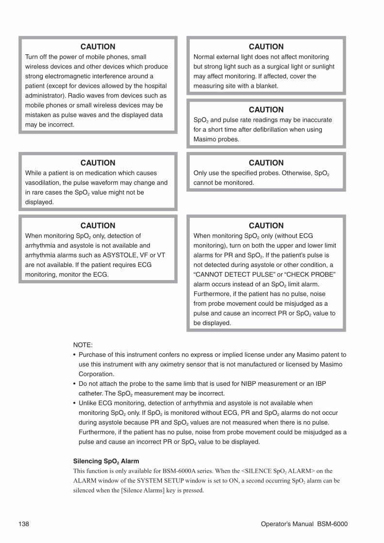
CAUTIONTurn off the power of mobile phones, small
wireless devices and other devices which produce
strong electromagnetic interference around a
patient (except for devices allowed by the hospital
administrator). Radio waves from devices such as
mobile phones or small wireless devices may be
mistaken as pulse waves and the displayed data
may be incorrect.
CAUTIONNormal external light does not affect monitoring
but strong light such as a surgical light or sunlight
may affect monitoring. If affected, cover the
measuring site with a blanket.
CAUTIONSpO2 and pulse rate readings may be inaccurate
for a short time after defibrillation when using
Masimo probes.
CAUTIONWhile a patient is on medication which causes
vasodilation, the pulse waveform may change and
in rare cases the SpO2 value might not be
displayed.
CAUTIONOnly use the specified probes. Otherwise, SpO2
cannot be monitored.
CAUTIONWhen monitoring SpO2 only, detection of
arrhythmia and asystole is not available and
arrhythmia alarms such as ASYSTOLE, VF or VT
are not available. If the patient requires ECG
monitoring, monitor the ECG.
CAUTIONWhen monitoring SpO2 only (without ECG
monitoring), turn on both the upper and lower limit
alarms for PR and SpO2. If the patient’s pulse is
not detected during asystole or other condition, a
“CANNOT DETECT PULSE” or “CHECK PROBE”
alarm occurs instead of an SpO2 limit alarm.
Furthermore, if the patient has no pulse, noise
from probe movement could be misjudged as a
pulse and cause an incorrect PR or SpO2 value to
be displayed.
NOTE:
• Purchase of this instrument confers no express or implied license under any Masimo patent to
use this instrument with any oximetry sensor that is not manufactured or licensed by Masimo
Corporation.
• Do not attach the probe to the same limb that is used for NIBP measurement or an IBP
catheter. The SpO2 measurement may be incorrect.
• Unlike ECG monitoring, detection of arrhythmia and asystole is not available when
monitoring SpO2 only. If SpO2 is monitored without ECG, PR and SpO2 alarms do not occur
during asystole because PR and SpO2 values are not measured when there is no pulse.
Furthermore, if the patient has no pulse, noise from probe movement could be misjudged as a
pulse and cause an incorrect PR or SpO2 value to be displayed.
Silencing SpO2 Alarm
This function is only available for BSM-6000A series. When the <SILENCE SpO2 ALARM> on the ALARM window of the SYSTEM SETUP window is set to ON, a second occurring SpO2 alarm can be silenced when the [Silence Alarms] key is pressed.
138 Operator’s Manual BSM-6000

Preparation
Select the appropriate probe according to purpose. To connect a Masimo probe to the SpO2 socket on the AY-631P or AY-633P input unit or the BSM-1733 bedside monitor, the JL-630P or JL-631P SpO2 connection cord is required. Use JL-630P with LNOP series probes and JL-631P with LNCS series probes. The Masimo probes are available direct from Masimo or their suppliers.
Monitoring SpO2 at two sites (dual SpO2) with Masimo probes are available. To monitor dual SpO2, the IF-925P communication cable and a Masimo pulse oximeter, Radical™, Radical-7™ or Rad-8™ are required. Connect a Masimo probe to the SpO2 socket on the AY-631P or AY-633P input unit or the BSM-1733 bedside monitor, another probe to the Masimo pulse oximeter and connect the pulse oximeter to the multi-link socket on the monitor with the IF-925P communication cable.
When Monitoring Dual SpO2
CAUTIONSome pulse oximeter alarms do not function on the bedside monitor when an pulse
oximeter is connected. When the data is abnormal, check the alarm on the pulse oximeter.
CAUTIONWhen two probes are attached too close to each other, the light from the probes interferes
with each other and SpO2 cannot be monitored properly. Make sure that there is no light
interference when attaching two probes.
NOTE:
• If a parameter is not monitored on the pulse oximeter, it is not displayed on the bedside
monitor.
• Some parameters cannot be displayed on the bedside monitor even if they are monitored on
the pulse oximeter.
• Waveforms from the pulse oximeter are not synchronized with the waveforms measured on
the bedside monitor.
• When the pulse oximeter is operating in power save mode, the bedside monitor cannot receive
data from the pulse oximeter. For details on the power save mode, refer to the pulse oximeter
manual.
• The pulse waveform displayed on the bedside monitor is affected by the operation on the
pulse oximeter. Depending on the status of the pulse oximeter, the pulse waveform displayed
on the bedside monitor may differ from the actual waveform.
e.g. The pulse waveform on the bedside monitor becomes flat while the trendgraph on the
pulse oximeter is updated.
Operator’s Manual BSM-6000 139
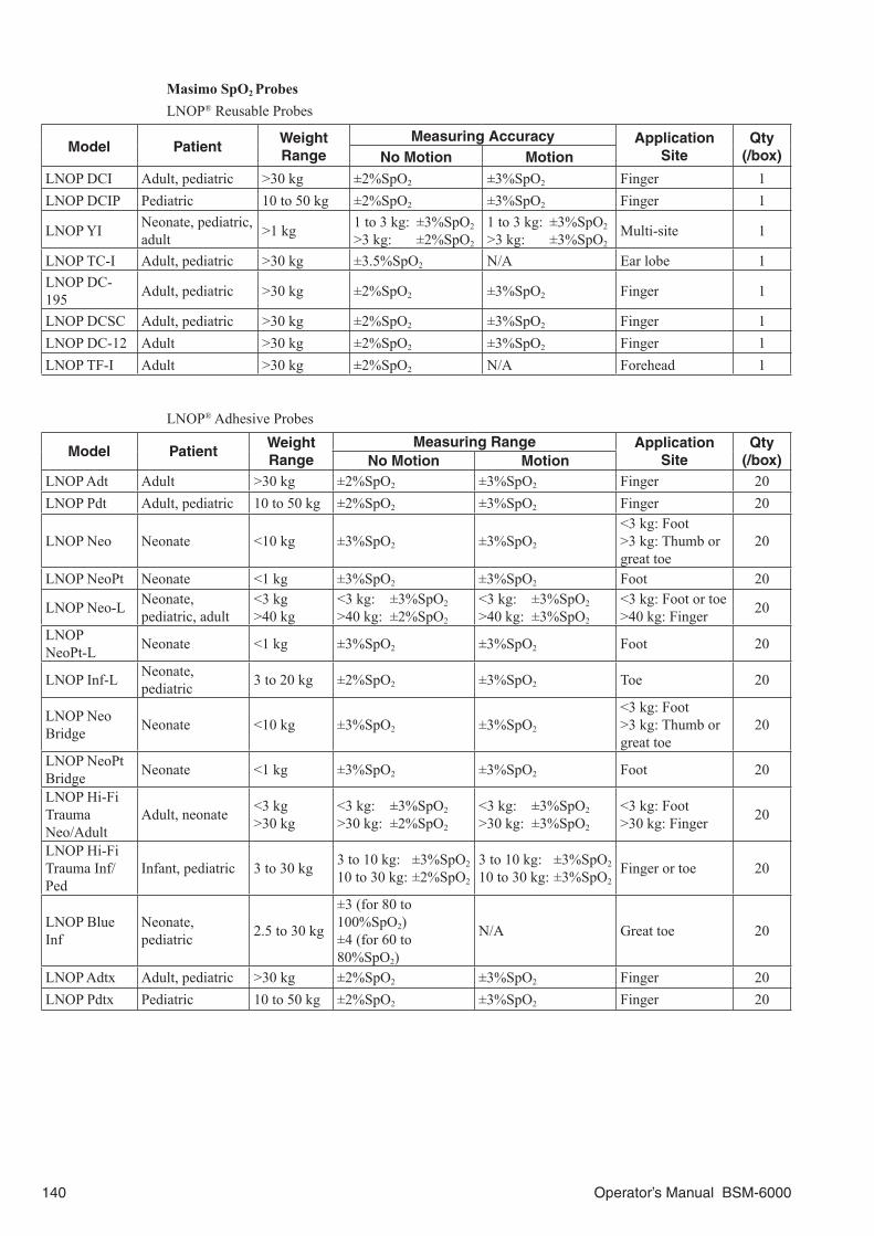
Masimo SpO2 ProbesLNOP® Reusable Probes
Model PatientWeight Range
Measuring Accuracy Application Site
Qty (/box)No Motion Motion
LNOP DCI Adult, pediatric >30 kg ±2%SpO2 ±3%SpO2 Finger 1LNOP DCIP Pediatric 10 to 50 kg ±2%SpO2 ±3%SpO2 Finger 1
LNOP YI Neonate, pediatric, adult >1 kg 1 to 3 kg: ±3%SpO2
>3 kg: ±2%SpO2
1 to 3 kg: ±3%SpO2
>3 kg: ±3%SpO2Multi-site 1
LNOP TC-I Adult, pediatric >30 kg ±3.5%SpO2 N/A Ear lobe 1LNOP DC-195 Adult, pediatric >30 kg ±2%SpO2 ±3%SpO2 Finger 1
LNOP DCSC Adult, pediatric >30 kg ±2%SpO2 ±3%SpO2 Finger 1LNOP DC-12 Adult >30 kg ±2%SpO2 ±3%SpO2 Finger 1LNOP TF-I Adult >30 kg ±2%SpO2 N/A Forehead 1
LNOP® Adhesive Probes
Model PatientWeight Range
Measuring Range Application Site
Qty(/box)No Motion Motion
LNOP Adt Adult >30 kg ±2%SpO2 ±3%SpO2 Finger 20LNOP Pdt Adult, pediatric 10 to 50 kg ±2%SpO2 ±3%SpO2 Finger 20
LNOP Neo Neonate <10 kg ±3%SpO2 ±3%SpO2
<3 kg: Foot>3 kg: Thumb or great toe
20
LNOP NeoPt Neonate <1 kg ±3%SpO2 ±3%SpO2 Foot 20
LNOP Neo-L Neonate, pediatric, adult
<3 kg>40 kg
<3 kg: ±3%SpO2
>40 kg: ±2%SpO2
<3 kg: ±3%SpO2
>40 kg: ±3%SpO2
<3 kg: Foot or toe>40 kg: Finger 20
LNOP NeoPt-L Neonate <1 kg ±3%SpO2 ±3%SpO2 Foot 20
LNOP Inf-L Neonate, pediatric 3 to 20 kg ±2%SpO2 ±3%SpO2 Toe 20
LNOP Neo Bridge Neonate <10 kg ±3%SpO2 ±3%SpO2
<3 kg: Foot>3 kg: Thumb or great toe
20
LNOP NeoPt Bridge Neonate <1 kg ±3%SpO2 ±3%SpO2 Foot 20
LNOP Hi-Fi Trauma Neo/Adult
Adult, neonate <3 kg>30 kg
<3 kg: ±3%SpO2
>30 kg: ±2%SpO2
<3 kg: ±3%SpO2
>30 kg: ±3%SpO2
<3 kg: Foot>30 kg: Finger 20
LNOP Hi-Fi Trauma Inf/Ped
Infant, pediatric 3 to 30 kg 3 to 10 kg: ±3%SpO2
10 to 30 kg: ±2%SpO2
3 to 10 kg: ±3%SpO2
10 to 30 kg: ±3%SpO2Finger or toe 20
LNOP Blue Inf
Neonate, pediatric 2.5 to 30 kg
±3 (for 80 to 100%SpO2)±4 (for 60 to 80%SpO2)
N/A Great toe 20
LNOP Adtx Adult, pediatric >30 kg ±2%SpO2 ±3%SpO2 Finger 20LNOP Pdtx Pediatric 10 to 50 kg ±2%SpO2 ±3%SpO2 Finger 20
140 Operator’s Manual BSM-6000

LNCS™ Reusable Probes
Model PatientWeight Range
Measuring Accuracy Application Site
Qty(/box)No Motion Motion
LNCS DCI Adult, pediatric >30 kg ±2%SpO2 ±3%SpO2 Finger 1LNCS DCIP Pediatric 10 to 50 kg ±2%SpO2 ±3%SpO2 Finger 1LNCS TC-I Adult, pediatric >30 kg ±3.5%SpO2 N/A Ear lobe 1LNCS TF-I Adult, pediatric >30 kg ±2%SpO2 N/A Forehead 1
LNCS™ Adhesive Probes
Model PatientWeight Range
Measuring Accuracy Application Site
Qty(/box)No Motion Motion
LNCS Adtx Adult, pediatric >30 kg ±2%SpO2 ±3%SpO2 Finger 20LNCS Pdtx Adult, pediatric 10 to 50 kg ±2%SpO2 ±3%SpO2 Finger 20LNCS Inf-L Neonate, pediatric 3 to 20 kg ±2%SpO2 ±3%SpO2 Toe 20
LNCS Neo-L Neonate, pediatric, adult
<3 kg>40 kg
±3%SpO2
±2%SpO2
±3%SpO2
±3%SpO2
<3 kg: Foot or toe>40 kg: Finger 20
LNCS NeoPt Neonate <1 kg ±3%SpO2 ±3%SpO2 Foot 20
When connecting the LNOP series probe
When connecting the LNCS series probe
JL-630P SpO2 connection cord JL-631P SpO2 connection cord
For details on how to connect a Masimo probe to the Masimo pulse oximeter, refer to the pulse oximeter manual. To connect the pulse oximeter to the multi-link socket on the monitor, refer to the IF-925P communication cable operator’s manual.
WARNINGDo not use additional tape to secure the probe to
patient.
CAUTIONWhen the probe is attached on an appropriate site
with sufficient circulation and an error message
about probe attachment repeatedly appears, the
probe may be deteriorated. Replace it with a new
one.
CAUTIONWhen a message indicates a faulty probe or faulty
SpO2 connection cord, stop monitoring and
replace the probe or SpO2 connection cord with a
new one.
Operator’s Manual BSM-6000 141

CAUTIONIf the attachment site is dirty with blood or bodily
fluids, clean the attachment site before attaching
the probe. If there is nail polish on the attachment
site, remove the polish. Otherwise, the amount of
transmitted light decreases, and measured value
may be incorrect or measurement cannot be
performed.
CAUTIONOnly use the specified probes. Otherwise, SpO2
cannot be monitored.
CAUTION• Do not reuse adhesive probes for another
patients because it causes cross infection.
• Do not use the probe over its stated lifetime.
Otherwise the SpO2 measurement accuracy
cannot be guaranteed.
• Do not immerse the Masimo probe in water
or any other solutions. The probe, cable and
connectors are not waterproof.
• Do not sterilize the probe by irradiation, steam or
ethylene oxide. Refer to the probe manual.
NOTE:
• In order to maintain sufficient blood circulation, keep the measurement site warm by covering
with a blanket or something similar. Warming the site is effective, especially for a patient with a
small pulse amplitude.
• Connect the probe and SpO2 connection cord until you hear a stopper of the SpO2 connection
cord click.
• When using Masimo probes, read the instructions provided with the probe.
Changing SpO2 Settings
Change settings on the SpO2 window. The following settings can be changed on the SpO2 tab for SpO2 monitoring.• Pulse waveform sensitivity• SpO2 and pulse rate alarm limits• Averaging time• Sensitivity mode• FAST SAT mode on or off• Display pulse rate and/or perfusion index in SpO2 numeric data area on the home screen• Display pulse rate to the left of the heart rate
The following settings can be changed on the SpO2-2 tab for dual SpO2 monitoring.• Pulse waveform sensitivity• ∆SpO2 alarm limit• Scale for SpO2-2 trendgraph on the home screen• Display SpO2-2 pulse rate, perfusion index and/or ∆SpO2 in SpO2-2 numeric data area on the home
screen
The following settings are common settings for SpO2 and SpO2-2.• Sync source• Sync sound pitch
The SpO2 data display color can be set on the SYSTEM SETUP window.
The scale of the SpO2 trendgraph on the home screen is the same scale as the trendgraph of the Review window.
142 Operator’s Manual BSM-6000
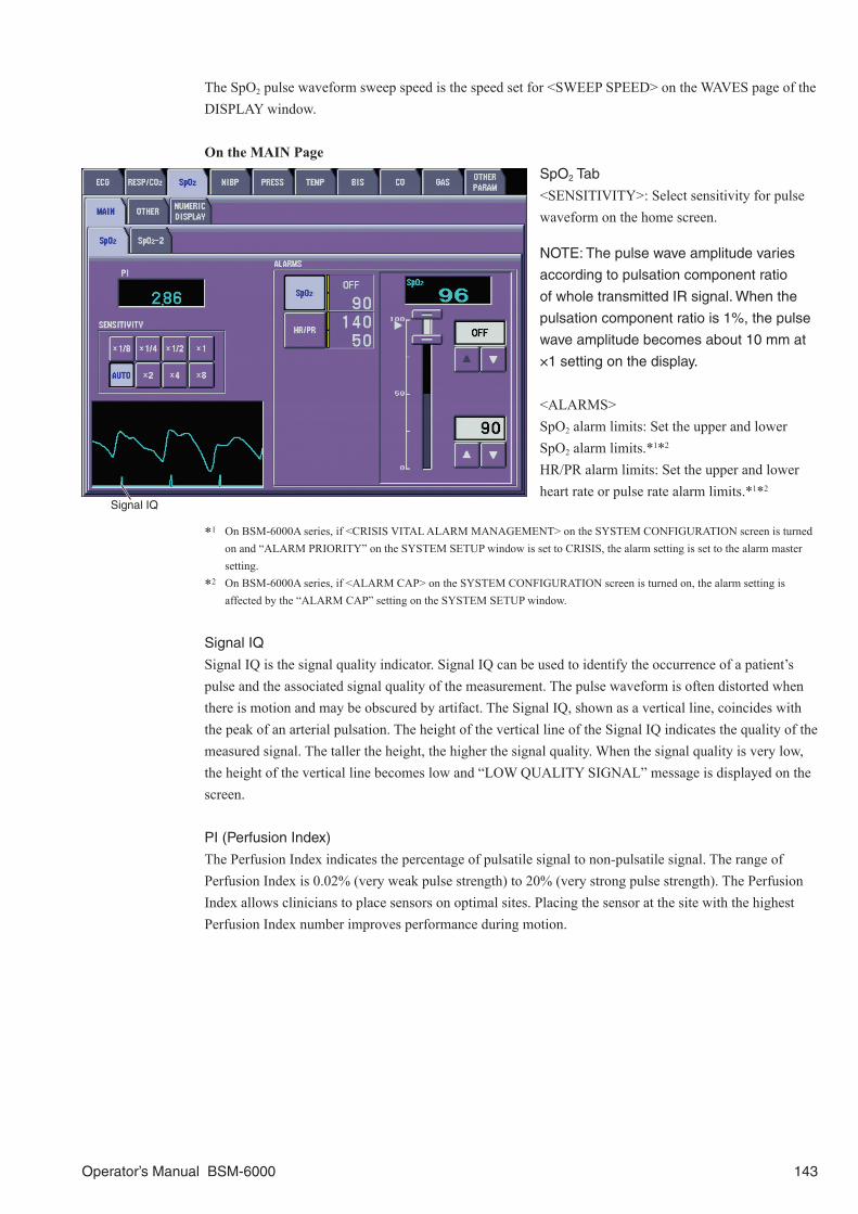
The SpO2 pulse waveform sweep speed is the speed set for <SWEEP SPEED> on the WAVES page of the DISPLAY window.
On the MAIN PageSpO2 Tab
<SENSITIVITY>: Select sensitivity for pulse waveform on the home screen.
NOTE: The pulse wave amplitude varies
according to pulsation component ratio
of whole transmitted IR signal. When the
pulsation component ratio is 1%, the pulse
wave amplitude becomes about 10 mm at
×1 setting on the display.
<ALARMS>SpO2 alarm limits: Set the upper and lower SpO2 alarm limits.*1*2
HR/PR alarm limits: Set the upper and lower heart rate or pulse rate alarm limits.*1*2
*1 On BSM-6000A series, if <CRISIS VITAL ALARM MANAGEMENT> on the SYSTEM CONFIGURATION screen is turned on and “ALARM PRIORITY” on the SYSTEM SETUP window is set to CRISIS, the alarm setting is set to the alarm master setting.
*2 On BSM-6000A series, if <ALARM CAP> on the SYSTEM CONFIGURATION screen is turned on, the alarm setting is affected by the “ALARM CAP” setting on the SYSTEM SETUP window.
Signal IQ
Signal IQ is the signal quality indicator. Signal IQ can be used to identify the occurrence of a patient’s pulse and the associated signal quality of the measurement. The pulse waveform is often distorted when there is motion and may be obscured by artifact. The Signal IQ, shown as a vertical line, coincides with the peak of an arterial pulsation. The height of the vertical line of the Signal IQ indicates the quality of the measured signal. The taller the height, the higher the signal quality. When the signal quality is very low, the height of the vertical line becomes low and “LOW QUALITY SIGNAL” message is displayed on the screen.
PI (Perfusion Index)
The Perfusion Index indicates the percentage of pulsatile signal to non-pulsatile signal. The range of Perfusion Index is 0.02% (very weak pulse strength) to 20% (very strong pulse strength). The Perfusion Index allows clinicians to place sensors on optimal sites. Placing the sensor at the site with the highest Perfusion Index number improves performance during motion.
Signal IQ
Operator’s Manual BSM-6000 143

SpO2-2 Tab
<SENSITIVITY>: Select sensitivity for SpO2-2 pulse waveform on the home screen.
NOTE: The pulse wave amplitude varies
according to pulsation component ratio
of whole transmitted IR signal. When the
pulsation component ratio is 1%, the pulse
wave amplitude becomes about 10 mm at
×1 setting on the display.
<ALARMS>ΔSpO2 alarm limit: Set the upper ΔSpO2 alarm limit.
On the OTHER Page<SYNC SOURCE>: Select the sync sound source from ECG (heart rate), SpO2 and arterial blood pressure (IBP).
NOTE:
• When heart rate is unstable because of
an ESU, select SpO2 or PRESS.
• When the SpO2 connection cord is
disconnected or the SpO2 probe is
detached and an alarm occurs, the sync
source changes to ECG (HR). The sync
source returns to SpO2 when the SpO2 is
measured again.
• When PRESS is selected while
monitoring low blood pressure, the pulse
rate becomes small and might not be
displayed correctly.
• The SpO2-2 cannot be set to the sync sound source.
<PR DISPLAY>: Select the pulse rate display on or off. This setting is only available when <SYNC SOURCE> is set to ECG.
<SYNC PITCH>: Select the sync sound pitch.FIXED: The pitch is fixed to the pitch selected on the SYSTEM SETUP window.PRESS: The pitch is high when the BP value is above 120 mmHg. The pitch is low when the BP value is below 20 mmHg. The pitch changes in 20 steps from high to low for each 5 mmHg change between 120 and 20 mmHg BP value. The BP value of the highest priority arterial blood pressure is used.SpO2: The pitch changes with each 1%SpO2 change in SpO2. You can select the SpO2 range (81 to 100%SpO2 or 40 to 100%SpO2) on the SYSTEM SETUP window. Refer to Section 3 of the Administrator’s Guide.
<AVERAGE TIME (s)>: Select the averaging time.
144 Operator’s Manual BSM-6000

<SENSITIVITY MODE>: Select the sensitivity mode.MAX: This mode should be used for a critical patient, where obtaining a reading is most difficult. MAX mode is designed to interpret and display data for even the weakest of signals. This mode is recommended during procedures and when clinician and patient contact is continuous.NORMAL: This mode provides the best combination of sensitivity and probe-off detection performance. This mode is recommended for most patients.APOD: APOD (Adaptive Probe Off Detection) is the least sensitive in picking up a reading on patients with low perfusion but has the best detection for probe-off conditions. This mode is useful for patients that are at particular risk of the sensor becoming detached (pediatric, body movement, etc.).
When MAX or APOD is selected, “SENS MAX” or “APOD” appears in the SpO2
value area on the home screen.
<FAST SAT>: FAST SAT enables rapid tracking of arterial oxygen saturation changes by minimizing the averaging. This mode is clinically applicable during procedures when detecting rapid changes in oxygen saturation is most important such as induction, intubation and sleep studies.
On the NUMERIC DISPLAY Page<NUMERIC DISPLAY ON HOME SCREEN FOR SpO2>: Select the PR and PI (Perfusion Index) display on or off in the SpO2 area on the home screen.
<NUMERIC DISPLAY ON HOME SCREEN FOR SpO2-2>: Select the PR, ΔSpO2 and PI (Perfusion Index) display on or off in the SpO2-2 area on the home screen.
Example: MAX is selected
Operator’s Manual BSM-6000 145

NIBPThe NIBP measurement can be used during electrosurgery and during the discharge of a cardiac defibrillator. This monitor complies with IEC 60601-2-30: 1999.
WARNINGBe careful when measuring NIBP on a patient with
known bleeding disorders or coagulation. After
NIBP measurement, there may be dot
hemorrhage, or circulatory disorder by thrombus
where the cuff is attached.
WARNINGNIBP measurement may be incorrect in the
following situations.
• When using an ESU
• Body movement
• Small pulse wave
• Too many arrhythmias
• Shaking from an external source
• Rapid blood pressure change
• During CPR
• Slow pulse
• Low blood pressure
• Cuff is too tight or too loose
• Cuff does not fit the arm
• Cuff is wrapped over thick clothing
• Cuff is deteriorated
Preparation
Select the appropriate cuff according to the patient. A YN-900P (1.5 m) or YN-901P (3.5 m) air hose is required. A YN-990P (1.5 m) extension hose is also available. When using cuff for neonates, a YN-920P (1.5 m) or YN-921P (3.5 m) air hose is required.
When connecting the YP-963P Cuff for Adults
146 Operator’s Manual BSM-6000

Reusable Cuffs
Cuff Width (cm) Applicable Circumference (cm)
For infantsYP-960T
5 8 to 13YP-710T
For childrenSmall
YP-961T7
12 to 18YP-711T 13 to 18
StandardYP-702T
10 15 to 23YP-962T
For adults
Small YP-712T* 10 18 to 23
StandardYP-703T
1321 to 30
YP-963TYP-713T* 23 to 33
LargeYP-964T 15 26 to 36
YP-714T* 16 33 to 45
For thighYP-965T
1933 to 45
YP-715T* 45 to 55
* Can be used for inflation method measurement when an Inflate Mode (iNIBP) compatible input unit is mounted on the BSM-6000K series bedside monitor.
Disposable Cuffs
Cuff Width (cm) Applicable Circumference (cm)Infants (Non-sterilized) YP-810P 6 8 to 14Children (Non-sterilized) YP-811P 8 13 to 20
Adults (Non-sterilized)
Small YP-812P 10 18 to 26Standard YP-813P 14 26 to 35Medium large YP-814P 15 29 to 38
Large YP-815P 17 32 to 42Extra large YP-816P 18 35 to 44
For thigh YP-817P 20 42 to 50
Neonates (Non-sterilized)
YP-820P 2 3 to 6YP-821P 3 4 to 8YP-822P 4 6 to 10YP-823P 4.5 7 to 13YP-824P 5 8 to 15
Connect the air hose to the NIBP socket.
CAUTIONFirmly connect the air hose to the NIBP socket on
the monitor until it clicks. If not connected properly,
the cuff type cannot be identified. At the start of
NIBP measurement, check if the cuff type
corresponds to the type displayed on the
monitoring screen.
CAUTIONWhen too much pressure is applied to the cuff, or
the hose is bent or squeezed, the “NIBP SAFETY
CIRCUIT RUNNING” message appears on the
screen and NIBP monitoring may be stopped.
Remove the cause, wait 40 seconds, check that
the message disappears, then measure again.
Operator’s Manual BSM-6000 147

CAUTIONDo not wrap the cuff too tight. It may cause poor
blood circulation and congestion. If the cuff is
wrapped too loosely, the NIBP value may increase.
CAUTIONDo not wrap the cuff on an arm or thigh which is
used for injection. NIBP measurement on an arm
or thigh which is used for injection may cause
reflux of blood and stop injection.
CAUTIONOnly connect the air hose to the cuff and NIBP
socket on the monitor. Do not connect the air hose,
especially the air hose for neonate, to other parts,
such as an infusion line. It may cause thrombus.
Changing NIBP Settings
Change settings on the NIBP window. The following settings can be changed for monitoring NIBP.• Initial cuff inflation pressure• Measurement mode and interval• NIBP alarm limits• Automatic measurement with PWTT on or off• Oscillation graph display on or off• Inflate mode on/off (Available only when an Inflate Mode (iNIBP) compatible input unit is mounted on
the BSM-6000K series bedside monitor)
The following items can be set on the SYSTEM SETUP window.• Measurement end sound• Starting NIBP auto measurement by pressing the [NIBP Interval] key• SIM mode measurement on or off• Measurement mode after the monitor power is off for more than 30 minutes or the monitor is initialized• Dim or hide the old measurement data• Time after NIBP measurement for the NIBP data to be dimmed or hidden• Measurement program for STAT and SIM modes• Measurement interval displayed on the NIBP INTERVALS window when the [NIBP Interval] key is
pressed• Venous puncture mode on or off and cuff inflation pressure for venous puncture• NIBP data display color
The NIBP unit (mmHg or kPa) is the same as the blood pressure unit. The pressure unit is set on the SYSTEM CONFIGURATION screen.
The scale of the NIBP trendgraph on the home screen is the same scale as the trendgraph of the Review window.
148 Operator’s Manual BSM-6000

On the MAIN Page<INITIAL CUFF PRESSURE TYPE>: Select the initial cuff inflation pressure type when the air hose for adult/child/neonate is connected to the NIBP socket.
NOTE: When the air hose for neonates
(1.5 m) is connected to the monitor and the
initial cuff pressure is set to 125 mmHg or
more, the actual pressure may be less than
the setting.
<ALARMS>SYS alarm limits: Set the upper and lower systolic alarm limits.DIA alarm limits: Set the upper and lower diastolic alarm limits.MAP alarm limits: Set the upper and lower mean alarm limits.
<MEASUREMENT INTERVAL>: Select the NIBP measurement mode.
On the PWTT PageTo automatically measure NIBP with PWTT, select ON for <PWTT MEASUREMENT>.
NOTE:
• PWTT is only available on the AY-660P,
AY-661P, AY-663P, AY-671P or AY-673P
input unit or the BSM-1763 or BSM-1773
bedside monitor and SpO2 is monitored
with Nihon Kohden probe.
• PWTT is not available when site is NICU
or the patient type is Neonate.
• PWTT is not available on BSM-6000A
series.
Operator’s Manual BSM-6000 149

On the OTHER Page<INITIAL CUFF PRESSURE>: Select the cuff inflation pressure for the first measurement. After the first measurement, the cuff inflation pressure is the systolic value of the previous measurement plus 30 mmHg.
To change the initial cuff inflation pressure for neonate, the air hose for neonate must be connected to the NIBP socket.
<DISPLAY OSCILLATION GRAPH>: Select whether to display the oscillation graph. However, the graph cannot be displayed when many parameters are monitored or NUMERIC PARAMETER AREA is set to SIDE + SMALL BOTTOM on the SYSTEM SETUP screen. Refer to “LAYOUT Page” in Section 3 of the administrator’s guide.
<INFLATE MODE>: Select whether to perform NIBP measurement in inflate mode. NOTE: INFLATE MODE is not available on BSM-6000A series.
WARNINGWhen measuring NIBP in INFLATE MODE, use a cuff specified by Nihon Kohden. If an
unspecified cuff is used, correct NIBP measurement might not be performed.
On the INTERVAL PageSelect the measurement modes for the mode selection by the [NIBP Interval] key on the bedside monitor.
The SIM mode is only available in the OR site and when <SIM> on the NIBP page of the PARAMETERS window is set to ON in the SYSTEM SETUP window.
150 Operator’s Manual BSM-6000

Starting and Stopping NIBP Measurement
After selecting measurement mode and interval, press the [NIBP Start/Stop] key on the bedside monitor.
To stop measurement, press the [NIBP Start/Stop] key again.
WARNINGWhen performing long term measurement at
intervals less than 2.5 minutes, perform
measurements while observing the state of the
patient, blood vessels and limb to ensure adequate
circulation. Congestion may occur at the
measurement site. When performing periodic
measurement for a long time, periodically check
the circulation condition.
CAUTIONWhen too much pressure is applied to the cuff, or
the hose is bent or squeezed, the “NIBP SAFETY
CIRCUIT RUNNING” message appears on the
screen and NIBP monitoring may be stopped.
Remove the cause, wait 40 seconds, check that
the message disappears, then measure again.
CAUTIONBefore starting STAT or SIM mode measurement,
check the measurement setting (measurement
intervals).
NOTE:
• When measuring patients who are conscious, help the patient to relax. Measurement may not
be accurate if the patient’s arm is tense or if the patient talks.
• The data for measurement on the thigh tends to be higher than measurement on the arm.
• Do not apply pressure to the cuff or air hose. NIBP might not be measured correctly because
of the noise or NIBP measurement may stop due to the NIBP safety circuit running.
• Do not bend or apply pressure on the air hose. It may cause noise and NIBP might not be
measured correctly.
• When NIBP START/STOP key is assigned to the function key, the NIBP measurement can
also be performed with the function key.
• Do not measure NIBP on a patient on whom an IABP is used. Accurate NIBP measurement
cannot be performed due to pulse waves from the IABP mixing with the patient’s pulse waves.
Measurement Mode and IntervalThere are four NIBP measurement modes: manual, auto (periodic), STAT (continuous) and SIM. The SIM mode is only available in OR site and when <SIM> is set to ON on the NIBP page of the PARAMETERS window in the SYSTEM SETUP window.
Manual Measurement
NIBP is measured once whenever the [NIBP Start/Stop] key on the monitor is pressed. Manual measurement cannot be performed during the first stage of the STAT or SIM mode measurement.
Operator’s Manual BSM-6000 151

Auto Measurement
The first NIBP measurement is performed when the [NIBP Start/Stop] key on the monitor is pressed. The second measurement is performed when the current time (minutes) in the monitor reaches the nearest time interval selected.
Auto Measurement with PWTT Trigger
NOTE:
• PWTT is only available on the AY-660P, AY-661P, AY-663P, AY-671P or AY-673P input unit
or the BSM-1763 or BSM-1773 bedside monitor and SpO2 is monitored with Nihon Kohden
probe.
• PWTT triggered NIBP measurement is not available when site is NICU, the patient type is
“Neonate” or the air hose for neonate is connected to the input unit, standard input unit or the
BSM-1700 series bedside monitor.
• PWTT is not available on BSM-6000A series.
To start PWTT trigger measurement, set PWTT Trigger NIBP Measurement to “On” on the PWTT window and set the NIBP SYS alarm limits on the MAIN page. Monitor ECG and SpO2. When stable PWTT is detected about one minute after ECG and SpO2 monitoring start, the mark appears. Measure NIBP once for calibration. When the calibration is finished, the border around the mark disappears and PWTT trigger measurement starts. When the NIBP SYS estimated by PWTT exceeds the alarm limits for eight seconds, the mark is highlighted and the NIBP is measured automatically.
CAUTIONDo not rely only on the PWTT trigger NIBP
measurement to monitor blood pressure changes.
When it is necessary to monitor critical blood
pressure change, set the appropriate interval for
NIBP measurement.
CAUTIONIn the following cases, PWTT may trigger too many
or no NIBP measurements. Check the patient
condition. If necessary, change the delta PWTT
threshold or set the PWTT to OFF.
• Rapid blood pressure change with vasoreflex
due to vasoactive drugs, such as phenylephrine
and nicardipine
• Unstable pulse wave due to poor peripheral
circulation
• Too many arrhythmias
• Patient movement
• Noise on ECG due to ESU
• SpO2 measurement on foot of a child
152 Operator’s Manual BSM-6000

NOTE:
• NIBP measurement with PWTT trigger is performed when ECG and SpO2 are monitored.
When ECG or SpO2 is not monitored, PWTT appears blank on the home screen.
• To avoid too frequent NIBP measurement, PWTT does not trigger NIBP measurement within
one minute of an NIBP measurement.
• If any of the following items are changed, PWTT changes discontinuously and estimated
NIBP SYS might not be accurate. After changing any of these items, calibrate (measure NIBP)
again.
- “LEAD” setting on ECG window
- Attachment place of the SpO2 probe
• When using PWTT triggered NIBP measurement, set <AUTO LEAD CHANGE> on the ECG
window to “OFF”. If you set this to “ON”, PWTT changes discontinuously and estimated NIBP
SYS might not be accurate when the lead is changed.
• In the following cases, the PWTT mark disappears and PWTT triggered NIBP measurement is
temporarily turned off. Remove the cause to turn on the PWTT triggered measurement.
- Noise interference on ECG or SpO2 and stable PWTT cannot be detected.
- An ECG electrode or SpO2 probe is detached and PWTT cannot be detected.
- The ECG, SpO2 or NIBP connector is disconnected.
- Both the upper and lower NIBP SYS alarm limits are set to off.
STAT Measurement
Measurements are performed continuously according to the measurement program set for STAT measurement on the STAT page on the NIBP MODE page of the PARAMETERS window in the SYSTEM SETUP window. The program is divided into two stages. In the first stage, NIBP is measured continuously or at 1 minute intervals for 5 or 10 minutes. In the second stage, NIBP is measured at a different interval (manual or 1, 2, 2.5, 5, 10, 15, 30 minutes, usually, longer interval than the first stage). Manual measurement cannot be performed during first stage measurement.
SIM Mode Measurement
CAUTIONFor safety during lumbar anesthesia, NIBP SIM mode measurement is recommended by
medical policy in Japan and the factory default settings are the recommended settings.
When changing these initial settings, make sure that the changed setting is appropriate for
the patient by referring to the manual of the anesthetic agent.
SIM mode program is for monitoring blood pressure during regional anesthesia, such as lumbar block, subarachnoid block and epidural anesthesia. The SIM mode is only available in OR site and when <SIM> on the NIBP page of the PARAMETERS window in the SYSTEM SETUP window is set to ON.
Measurements are performed continuously according to the measurement program set for SIM measurement on the SIM tab of the NIBP MODE page of the PARAMETERS window in the SYSTEM SETUP window.
The program is divided into two stages. In the first stage, NIBP is measured at 1, 2 or 2.5 minute intervals for 5, 10 or 15 minutes. In the second stage, NIBP is measured at a different interval (2, 2.5 or 5 minutes, usually longer interval than the first stage). Manual measurement cannot be performed during first stage measurement.
Operator’s Manual BSM-6000 153
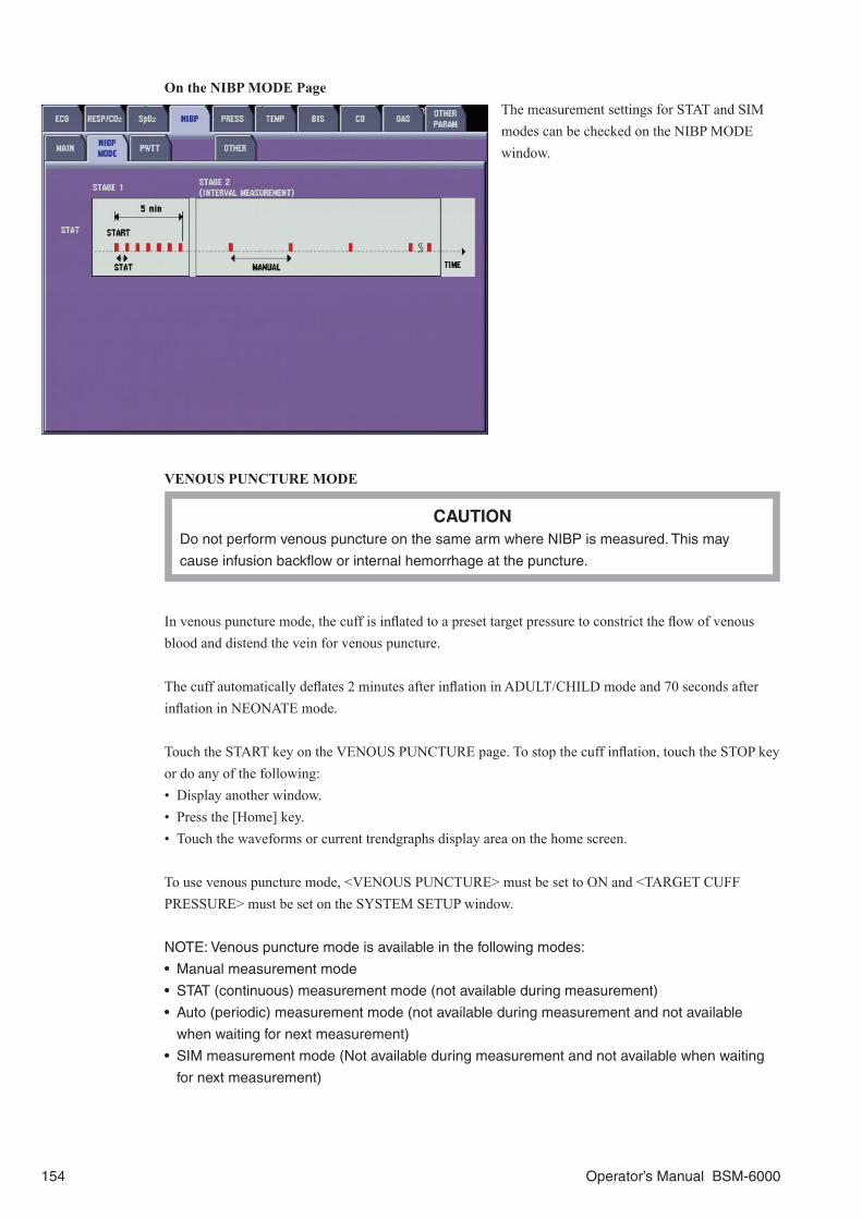
On the NIBP MODE PageThe measurement settings for STAT and SIM modes can be checked on the NIBP MODE window.
VENOUS PUNCTURE MODE
CAUTIONDo not perform venous puncture on the same arm where NIBP is measured. This may
cause infusion backflow or internal hemorrhage at the puncture.
In venous puncture mode, the cuff is inflated to a preset target pressure to constrict the flow of venous blood and distend the vein for venous puncture.
The cuff automatically deflates 2 minutes after inflation in ADULT/CHILD mode and 70 seconds after inflation in NEONATE mode.
Touch the START key on the VENOUS PUNCTURE page. To stop the cuff inflation, touch the STOP key or do any of the following:• Display another window.• Press the [Home] key.• Touch the waveforms or current trendgraphs display area on the home screen.
To use venous puncture mode, <VENOUS PUNCTURE> must be set to ON and <TARGET CUFF PRESSURE> must be set on the SYSTEM SETUP window.
NOTE: Venous puncture mode is available in the following modes:
• Manual measurement mode
• STAT (continuous) measurement mode (not available during measurement)
• Auto (periodic) measurement mode (not available during measurement and not available
when waiting for next measurement)
• SIM measurement mode (Not available during measurement and not available when waiting
for next measurement)
154 Operator’s Manual BSM-6000

VENOUS PUNCTURE PageCUFF PRESSURE: Displays the current cuff pressure (mmHg).TARGET CUFF PRESSURE: Displays the set target cuff pressure (mmHg).REMAINING TIME: Displays the remaining time (s) until cuff deflation.
Operator’s Manual BSM-6000 155

IBPInvasive blood pressure and intracranial pressure (ICP) are measured and monitored by installing the blood pressure measuring device, connecting the blood pressure transducer to the IBP connection cord and IBP connection cord to the MULTI socket or PRESS CO2 socket on the unit. Up to 7 channels can be monitored. When the ZS-900P transmitter is connected to the bedside monitor and an AY-633P, AY-653P, AY-663P or AY-673P input unit or the BSM-1700 series bedside monitor with three MULTI sockets is used for IBP monitoring, only the IBP information from the two sockets from the top can be sent.NOTE: ZS-900P transmitter is not available for BSM-6000A series.
Preparation
Select the appropriate blood pressure measuring device according to the purpose. The following illustrates a typical blood pressure measuring device setup, the DX-360 Argon Medical Devices disposable blood pressure transducer. For details, refer to the instruction manual of the measuring kit. When using other blood pressure transducers and measuring kits, refer to the respective instruction manuals..
WARNINGAll parts, except for transducers, must be non conductive.
Otherwise, the discharged energy may cause electrical
shock to the operator during defibrillation.
IBP Connection CordsThe following IBP connection cords are available for connecting the device to the monitor.JP-900P: For Argon Medical Devices blood pressure transducersJP-911P: For Integra NeuroSciences Camino® MPM-1 multi- parameter monitorJP-920P: For Edwards Lifesciences (Baxter) blood pressure transducersJP-960P: For Biosensor blood pressure transducersJP-910P: For other blood pressure transducers
Connecting Cables to the Unit
1. Connect the blood pressure transducer to the IBP connection cord.
2. Connect the IBP connection cord to the MULTI socket on the unit.
NOTE:
• When using an IBP waveform as a synchronization signal for other equipment, connect the
IBP line to the MULTI socket. The IBP waveform that is used for the synchronization signal
depends on the “IBP ANALOG OUT” setting in the SYSTEM SETUP window.
- When “IBP ANALOG OUT” is set to FIXED POSITION:
The IBP line connected to the top MULTI socket is used.
- When “IBP ANALOG OUT” is set to HIGHEST PRIORITY LABEL:
When more than one IBP waveform is acquired, the IBP waveform of the highest priority
label is used.
IBP label priority:
ART > ART2 > RAD > DORS > AO > FEM > UA > LVP > P1 > P2 > P3 > P4 > P5 > P6 > P7
Extension tube 30 cm
Extension tube 120 cmMicro drip with filter
Roller clamp
Infusion tube 150 cm
IBP connection cord
156 Operator’s Manual BSM-6000

• When connecting the IBP connection cord to the unit after assembling the transducer and
filling the tubes with saline solutions, make sure that the connector is not wet.
Assembling the Transducer
NOTE:
• For caution and usage of the transducer, refer to the manual of the transducer.
• The DX series disposable transducers are sterilized by EOG. Keep them clean after opening.
• Check that connectors and caps are firmly connected and the 3-way stopcock are directed to
the correct way.
• The 3-way stopcocks and blood pressure tube openings are protected from contamination
by the white aerated caps. Keep these white caps on until the solution is filled in completely.
After filling the solution, replace the white caps with the yellow sealing caps which are in the
separate bag.
1. Inject 1 to 2 units of heparin into 1 mL sterilized physiological saline solution.NOTE: Do not mix the solution yet.
2. Insert the needle at the tip of the micro-drip into the hole on the physiological saline pack.
3. Pressurize the physiological saline pack with your hand by pressing the flush cap to remove air from the pack.
4. When the solution in the micro-drip chamber is about 1/3 full (the stainless needle is in the solution), turn the physiological saline pack upside down and mix the physiological saline solution and heparin.
5. Place the saline pack in the pressure bag and hang the pressure bag on the stand.
6. Press the flush cap to completely fill the tube with saline solution.NOTE: Tap the bottom part of the micro-drip to remove air bubbles from under the filter.
7. Fill in the transducer with the saline solution. Remove air bubbles by pressing the flush cap at above the saline pack, then bringing the flush cap down.
If the air bubbles cannot be removed from the transducer:i) Hold the transducer higher than the saline pack to flow the saline solution back into the saline
pack and fill the transducer again.ii) Tap the transducer lightly and flush the transducer slowly. Do not tap too hard because the air
bubbles may break into small bubbles which are difficult to remove.iii) Check that there are no air bubbles in the transducer, tubes and 3-way stopcocks.
8. Replace the white aerated caps with the yellow sealing caps.
9. Pressurize the pressure bag to 300 mmHg (40.0 kPa). The solution in the micro-chip chamber is about a third to half full.
At this pressure, the drip rate should be 2 to 4 drops/min.
10. Check all connections and that there is no leakage in the circuit.
11. After about 30 minutes, check the pressure of the pressure bag and drip rate. Also check that there is no leakage in the circuit.
Operator’s Manual BSM-6000 157

Adjusting Zero Balance
NOTE: There is no alarm for 30 seconds after adjusting zero balance. When the measurement
value is abnormal, the numeric value on the screen is highlighted.
Adjust zero balance in the following cases. Zero balance adjustment is important for accurate IBP measurement.• Before starting measurement.• When the patient moved so that the height of the heart changed.• When the height of the blood pressure transducer changes.• When changes in the measured value are expected due to measurements over a long period of time or
due to changes in the ambient temperature (check the pressure when exposed to air).• IBP connection cord or transducer is changed.
When the zero balance is not adjusted, the “ZERO IMBALANCE” message is displayed beside each IBP value.
Zero Balance ModeThere are two modes for adjusting zero balance.
• All zero Zero balance of all blood pressure lines exposed to air, except for ICP, is performed at the same time. Touch the ZERO ALL key on the PRESS window. The zero all function can also be assigned to one of
the function keys.
Adjust zero balance separately for ICP (intracranial pressure).
• Individual zero The zero balance is adjusted individually for one pressure line. Touch the ZERO CAL key on the PRESS window of the IBP label (including the ICP label).
When using the optional JP-940P IBP connection box, the zero balance keys on the box can be used for each line.
Adjusting Zero Balance1. When zero balance is not adjusted, the following dialog box appears.
2. Touch the YES key to adjust zero balance. When the YES key is touched, the MAIN page of the PRESS window appears. Adjust zero balance by doing the following steps.
When the NO key is touched, the monitor starts monitoring IBP by using the zero balance value memorized in the connector of the IBP connection cord and the “ZERO IMBALANCE” messages disappear. The IBP values appear on the screen. If necessary, adjust zero balance by doing the following steps.
3. Move the dome up or down to the appropriate position.
158 Operator’s Manual BSM-6000

4. To adjust zero balance of all blood pressure lines at the same timeNOTE: Zero balance cannot be adjusted for ICP by using the zero all function. Adjust zero balance separately from the ICP window.
Touch the ZERO ALL function key on the home screen or the ZERO ALL key on the MAIN page of the PRESS window.
To adjust zero balance individually Touch the ZERO CAL key on the desired LABEL page of the PRESS window.
When the “ZEROING COMPLETE” message is displayed, zero balance adjustment is complete.
5. Close the 3-way stopcock.
The CHECK ZERO Page
This page becomes active when zero balance is not adjusted. Zero balance can also be adjusted on the CHECK ZERO page.
Changing IBP Settings
Change settings on the PRESS window. The following settings can be changed for monitoring IBP.• Label• Scale• IBP alarm limits• Adjust zero balance. Refer to the “Adjusting Zero Balance” section.• IBP calculation mode• Numeric data display mode• CPP display on or off• Auto ET mode for CVP mean calculation on or off• Sync source• Sync sound pitch• Pulse rate display on or off• Waveform display mode (scale mode)• PPV/SPV display on or off• PPV/SPV average time
Operator’s Manual BSM-6000 159

The blood pressure unit (mmHg or kPa) can be set on the SYSTEM CONFIGURATION screen.The noise filter and IBP data display color can be set on the SYSTEM SETUP window.
The IBP waveform sweep speed and the waveform display of all monitoring IBP labels on the home screen can be selected on the DISPLAY window.
On the LABEL PageSelect the blood pressure label for the line connected to the MULTI socket from the <SELECTABLE ITEMS> box.
NOTE: The blood pressure label is fixed to
ART when a JP-600P APCO/IBP processor
is used.
On the SCALE PageSelect the scale for the blood pressure line waveform on the home screen. The same scale is used on both the home screen and PRESS window.
You can touch the AUTO ADJUST key to automatically select the appropriate scale.
160 Operator’s Manual BSM-6000

On the MAIN Page<ALARMS>SYS alarm limits: Set the upper and lower systolic alarm limits.*1
DIA alarm limits: Set the upper and lower diastolic alarm limits.*1
MEAN alarm limits: Set the upper and lower mean alarm limits.*1
HR/PR alarm limits: Set the upper and lower heart rate or pulse rate alarm limits.*1*2
*1 On BSM-6000A series, if <ALARM CAP> on the SYSTEM CONFIGURATION screen is turned on, the alarm settings for ART (SYS, DIA, MEAN), PAP (SYS, DIA, MEAN), CVP (MEAN) and HR/PR are affected by the “ALARM CAP” setting on the SYSTEM SETUP window.
*2 On BSM-6000A series, if <CRISIS VITAL ALARM MANAGEMENT> on the SYSTEM CONFIGURATION screen is turned on and “ALARM PRIORITY” on the SYSTEM SETUP window is set to CRISIS, the alarm setting is set to the alarm master setting.
On the OTHER Page<SYNC SOURCE>: Select the sync sound source from ECG (heart rate), arterial blood pressure (IBP) and SpO2.
NOTE:
• When heart rate is unstable because of
an ESU, select SpO2 or PRESS.
• When the SpO2 connection cord is
disconnected or the SpO2 probe is
detached and an alarm occurs, the sync
source changes to ECG (HR). The sync
source returns to SpO2 when the SpO2 is
measured again.
• The SpO2-2 cannot be set to the sync
sound source.
<PR DISPLAY>: Select the pulse rate display on or off. This setting is only available when <SYNC SOURCE> is set to ECG.
<CALCULATION METHOD>: Select the IBP calculation mode.STANDARD: The IBP values are calculated by moving average. The monitor averages the latest 8 consecutive pulses and displays this average as the IBP value. When a new pulse is detected, the IBP value is recalculated using the latest 8 pulses. The IBP value display is updated every 3 seconds.PEAK: The systolic, diastolic and mean values of the highest pulse wave in the latest 8 consecutive pulses are displayed as the IBP values. The IBP value display is updated every 3 seconds.When connected IABP causes the IBP values to vary greatly, use PEAK to improve measurement accuracy.
Operator’s Manual BSM-6000 161

<CPP DISPLAY>: Select the CPP display on the home screen ON or OFF when monitoring ICP.
<NUMERIC DISPLAY>: Select the IBP/ICP display mode on the home screen.SYS/DIA(MEAN): Displays the systolic blood pressure (SYS), diastolic blood pressure (DIA) and the averaged blood pressure (MEAN).MEAN: Displays only the averaged blood pressure.
<SYNC PITCH>: Select the sync sound pitch.FIXED: The pitch is fixed to the pitch selected on the SYSTEM SETUP window.PRESS: The pitch is high when the BP value is above 120 mmHg. The pitch is low when the BP value is below 20 mmHg. The pitch changes in 20 steps from high to low for each 5 mmHg change between 120 and 20 mmHg BP value. The BP value of the highest priority arterial blood pressure is used.SpO2: The pitch changes in 20 steps from high to low for each 1%SpO2 change between 100%SpO2 and 81%SpO2 in SpO2 value of SpO2 connected to the SpO2 socket.SpO2-2: The pitch changes in 20 steps from high to low for each 1%SpO2 change between 100%SpO2 and 81%SpO2 in SpO2 value of SpO2-2 connected to the MULTI socket. SpO2-2 is only available for the AY-661P, AY-663P, AY-671P or AY-673P input unit or BSM-1763 or BSM-1773 bedside monitor.
<PRESS SCALE>: Select the display mode for IBP waveforms.SEPARATE: IBP waveforms are displayed separately on different scales.COMMON: All IBP waveforms are displayed on the same scale.DUAL: IBP waveforms are separated into arterial blood pressures and other type of blood pressures. The arterial blood pressures are labeled ART, ART-2, RAD, DORS, AO, FEM, UA, LVP and PRESS (P1 to P7).
<CVP AUTO ET MODE>: Select the auto ET mode for CVP mean calculation on or offOn: Automatically uses the ET mode to calculate the mean CVP. When CO2 is not monitored in mainstream method with the TG-900P, TG-920P, TG-950P, TG-970P or TG-980P CO2 sensor kit, the mean CVP is calculated in normal mode. When the ET mode is used, “CVP_ET” appears for the CVP value on the home screen.Off: The mean CVP is calculated in normal mode every 3 seconds.
NOTE:
• To use the ET mode, CO2 must be monitored with the TG-900P, TG-920P, TG-950P, TG-970P
or TG-980P CO2 sensor kit.
• In the following cases, the mode automatically changes from ET to normal mode:
- Cannot detect changes from expiration to inspiration for more than 20 seconds.
- The CO2 sensor connector is not connected or disconnected from the socket.
- CO2 cannot be monitored due to CO2 sensor failure
- CO2 is not monitored with a TG-900P, TG-920P, TG-950P, TG-970P or TG-980P CO2 sensor
kit.
• When the ET mode is used, the mean CVP might not be calculated at the appropriate end-
tidal point due to the CO2 sensor attachment or patient’s respiration state. When using the ET
mode, check that the CVP value is appropriate by reading the CVP waveform on the screen.
• The mean CVP value obtained by the ET mode might not be accurate due to patient
movement or unstable respiration.
• When “NUMERIC DISPLAY” is set to SYS/DIA (MEAN), the ET mode is used for the
calculation, but “CVP” appears instead of “CVP_ET” for the CVP value on the home screen.
162 Operator’s Manual BSM-6000

<PPV/SPV DISPLAY>: Select PPV or SPV to be displayed on the home screen. Select OFF when not displaying either PPV or SPV.
NOTE:
• PPV or SPV of IBP with the highest priority label of arterial blood pressure (ART, ART2,
RAD, DORS, AO or FEM) is displayed. If the connection cord of IBP whose PPV or SPV
is monitored is disconnected from the monitor, PPV or SPV of the blood pressure with the
second priority label is monitored. If the disconnected IBP is connected again, PPV or SPV of
the highest priority label is monitored again. In such a case, adjust zero balance.
• PPV or SPV is accurately measured when the patient is using a ventilator and when there is
no patient movement and no arrhythmias. In the following cases, PPV or SPV is not accurate
or cannot be measured.
- Patient movement
- Spontaneous respiration
- Arrhythmia
- Respiration rate less than 6 counts/min
- Ventilation volume less than 8 mL/kg
- Acute right heart failure
• This setting is common for all IBP labels. It only needs to be set on one label window.
<PPV/SPV AVERAGE TIME>: Select the averaging time for PPV or SPV display. 5 min is appropriate for monitoring variation for long term (more than an hour) with less noise interference.
NOTE:
• This setting is only available when “PPV” or “SPV” is selected for the <PPV/SPV DISPLAY>
setting.
• This setting is common for all IBP labels. It only needs to be set on one label window.
Operator’s Manual BSM-6000 163
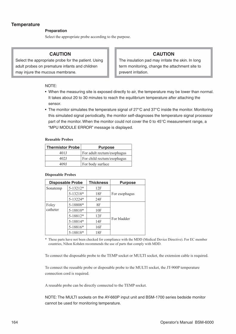
TemperaturePreparation
Select the appropriate probe according to the purpose.
CAUTIONSelect the appropriate probe for the patient. Using
adult probes on premature infants and children
may injure the mucous membrane.
CAUTIONThe insulation pad may irritate the skin. In long
term monitoring, change the attachment site to
prevent irritation.
NOTE:
• When the measuring site is exposed directly to air, the temperature may be lower than normal.
It takes about 20 to 30 minutes to reach the equilibrium temperature after attaching the
sensor.
• The monitor simulates the temperature signal of 27°C and 37°C inside the monitor. Monitoring
this simulated signal periodically, the monitor self-diagnoses the temperature signal processor
part of the monitor. When the monitor could not cover the 0 to 45°C measurement range, a
“MPU MODULE ERROR” message is displayed.
Reusable Probes
Thermistor Probe Purpose401J For adult rectum/esophagus402J For child rectum/esophagus409J For body surface
Disposable Probes
Disposable Probe Thickness PurposeSonatemp 5-13212* 12F
For esophagus5-13218* 18F5-13224* 24F
Foley catheter
5-18808* 8F
For bladder
5-18810* 10F5-18812* 12F5-18814* 14F5-18816* 16F5-18818* 18F
* These parts have not been checked for compliance with the MDD (Medical Device Directive). For EC member countries, Nihon Kohden recommends the use of parts that comply with MDD.
To connect the disposable probe to the TEMP socket or MULTI socket, the extension cable is required.
To connect the reusable probe or disposable probe to the MULTI socket, the JT-900P temperature connection cord is required.
A reusable probe can be directly connected to the TEMP socket.
NOTE: The MULTI sockets on the AY-660P input unit and BSM-1700 series bedside monitor
cannot be used for monitoring temperature.
164 Operator’s Manual BSM-6000

When connecting the 409J reusable probe for the body surface to the TEMP socket
When connecting the 409J reusable probe for the body surface to the MULTI socket
JT-900P temperature connection cord
Using the Insulation Pad
The pad prevents the environmental temperature from affecting the sensor temperature and also prevents internal body heat from escaping at the attached site so that a stable temperature is obtained.
Changing Temperature Settings
Change settings on the TEMP window. The following settings can be changed for monitoring temperature.• Label• Temperature alarm limits• Delta temperature equation setting
The temperature unit can be set to °C or °F on the SYSTEM CONFIGURATION screen.
The temperature data display color can be set on the SYSTEM SETUP window.
On the MAIN Page<ALARMS>Temperature alarm limits: Set the upper and lower temperature alarm limits.
Operator’s Manual BSM-6000 165

On the LABEL Page
CAUTIONAfter changing the temperature label, do not reconnect the probe to another jack. This may
cause an incorrect label display and lead to misjudgment.
Select the site to be labeled and select the label from <SELECTABLE ITEMS> box.
On the OTHER PageTemperature difference for two pairs of temperatures can be selected.
<∆T SITES>: Set the temperature difference equations to measure temperature differences.Select the label for the first temperature and second temperature from <SELECTABLE ITEMS> box.
<∆T2 SITES>: Set the temperature difference equations to measure temperature differences.Select the label for the first temperature and second temperature from <SELECTABLE ITEMS> box.
If you do not need to monitor temperature difference, select NONE in <ΔT SITES> or <ΔT2 SITES> box.
First temperature Second temperature
166 Operator’s Manual BSM-6000
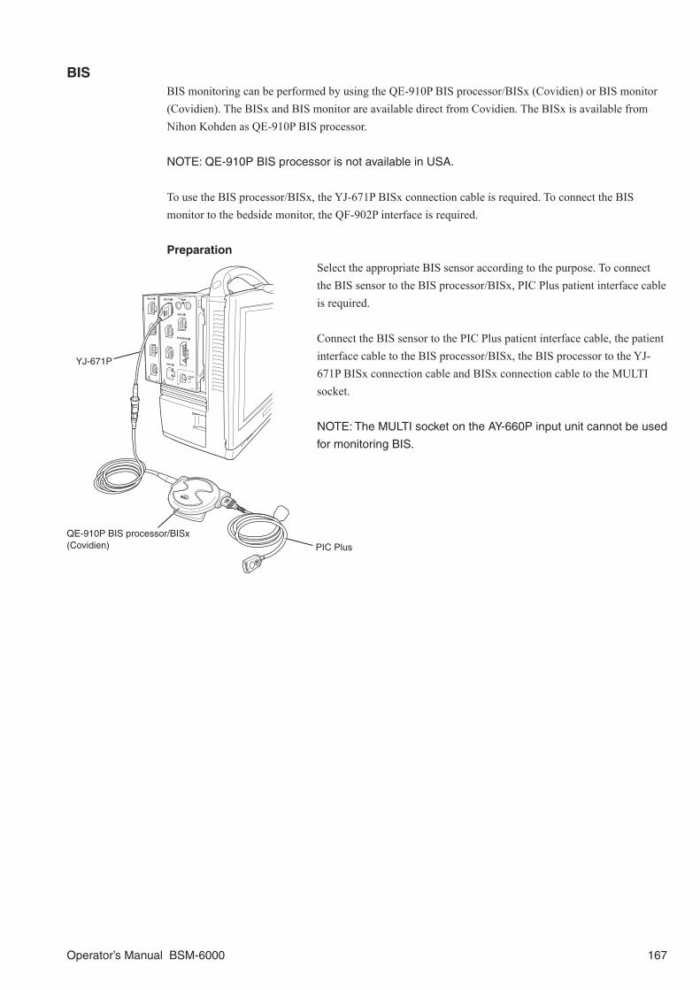
BISBIS monitoring can be performed by using the QE-910P BIS processor/BISx (Covidien) or BIS monitor (Covidien). The BISx and BIS monitor are available direct from Covidien. The BISx is available from Nihon Kohden as QE-910P BIS processor.
NOTE: QE-910P BIS processor is not available in USA.
To use the BIS processor/BISx, the YJ-671P BISx connection cable is required. To connect the BIS monitor to the bedside monitor, the QF-902P interface is required.
Preparation
Select the appropriate BIS sensor according to the purpose. To connect the BIS sensor to the BIS processor/BISx, PIC Plus patient interface cable is required.
Connect the BIS sensor to the PIC Plus patient interface cable, the patient interface cable to the BIS processor/BISx, the BIS processor to the YJ-671P BISx connection cable and BISx connection cable to the MULTI socket.
NOTE: The MULTI socket on the AY-660P input unit cannot be used
for monitoring BIS.
PIC Plus
YJ-671P
QE-910P BIS processor/BISx (Covidien)
Operator’s Manual BSM-6000 167

WARNINGDo not place the BIS monitor or BIS processor
above the patient. When installing the BIS monitor,
use the pole clamp to firmly attach the BIS monitor
to a secure pole (1.0 to 3.8 cm in diameter).
Periodically check that the pole clamp knob is not
loose. Use the clip on the back of the BIS
processor to attach the BIS processor to the bed
rail or pole. If the BIS monitor or BIS processor is
not attached to a rail or pole, install it where it
cannot fall or tip over. Otherwise, it may cause
injury to the patient or operator.
WARNINGIt is reported that BIS monitoring is not appropriate
when an analgesic anesthetic agent, such as
ketamin, fentanyl, morphine, or only a muscle
relaxant is used.
WARNINGDo not perform defibrillation with the BIS sensor
placed between the defibrillator pads.
WARNINGThe conductive parts of electrodes or sensor and
connectors, including the neutral electrode, should
not contact other conductive parts, including earth.
WARNINGThe hypnotic state of a patient undergoing surgery
is influenced by the intensity of stimulation that is
applied. During the course of a surgical procedure,
the balance between the intensity of stimulation
and sensory suppression may be constantly
changing. Read the BIS value carefully.
WARNINGReliance on the BIS alone for intraoperative
anesthetic management is not recommended.
Clinical judgement (patient face color, patient
reaction, heart rate, blood pressure and other vital
sign data) should always be used. BIS has been
studied with the anesthetic agents listed in the
“Drugs that have been Studied for Use with the
BIS” section in the BIS reference guide, but the
studied data are relative values and do not indicate
the absolute value of the hypnotic level.
WARNINGDue to limited clinical experience in the following
applications, BIS values should be interpreted
cautiously in patients with known neurological
disorders such as epilepsy, patients taking other
psychoactive medications, patients with cerebral
infarction and in children below the age of 18.
CAUTIONWhen performing electroconvulsive therapy (ECT),
attach the BIS sensor as far as possible from the
electrodes that are used for electrical shock.
Otherwise noise from the electrodes may interfere
and incorrect data is displayed on the screen.
CAUTION• The BIS sensor is single use only. Do not reuse
it.
• Do not reuse the BIS sensor for another patient.
There are a lot of fine projections on the BIS
sensor. Reusing the BIS sensor for another
patient may cause infection to another patient by
bacteria adhering to the BIS sensor.
• Do not use the BIS sensor for more than 24
hours. It affects monitoring accuracy.
CAUTIONDo not use an expired BIS sensor.
CAUTIONTo minimize the risk of patient strangulation, the
PIC Plus patient interface cable must be carefully
placed and secured.
168 Operator’s Manual BSM-6000

CAUTIONTurn off the automatic impedance check if the
impedance check signal (1 nA, 128 Hz) interferes
with other equipment.
CAUTIONDo not let the BIS processor continuously contact
the patient’s body. The BIS processor heats up
during operation and it may cause low temperature
burn to the patient.
CAUTIONWhen attaching the BIS sensor to the patient,
press each electrode on the sensor for 5 seconds
to reduce impedance between the electrode and
skin.
CAUTIONWhen the “BIS CONNECTOR OFF” message is
displayed, check that the BIS processor is firmly
connected to the connection cable and connection
cable is firmly connected to the monitor. The BIS
cannot be monitored and the alarm does not
function while this message is displayed.
CAUTIONOnly use the specified BIS sensor.
CAUTIONThe BIS processor cannot be sterilized. Sterilizing
the BIS processor may damage it.
Operator’s Manual BSM-6000 169

CAUTION• The following physiological factors and external factors must be considered in BIS
monitoring.
1. Ischemia or hypoxia, when severe enough to cause global EEG slowing or outright
suppression, results in a decrease in the BIS value. It is important to bear in mind that
the frontal montage used for BIS monitoring usually will not detect episodes of focal
ischemia caused by embolic events.
2. Hypothermia will generally result in a corresponding decrease in BIS levels as brain
processes slow. More profound hypothermia used during cardiac bypass procedures
will cause suppression of the EEG and, consequently, a very low BIS.
3. Artifacts and signal of poor quality cause the BIS to be unreliable. Such artifacts are
caused by poor contact of sensor to skin, muscle activity or rigidity, head or body
movement, eye movement, inappropriate sensor attachment and other electrical
interference. Some examples are given below.
a) Hum noise: Usually there is no hum interference, but when the hum filter is turned
off and a signal larger than 100 μV is superimposed on the EEG waveform on the
screen, BIS may increase.
b) ESU (unipolar):The noise generated by unipolar ESU is so large that it saturates
the EEG signal so that EEG waveforms cannot be acquired. BIS value first blinks
(SQI decreases) and then disappears. After stopping the use of the ESU, BIS value
is displayed again.
c) ESU (bipolar): Bipolar ESU causes low amplitude high frequency wave signals
which may be mistaken as EEG and thus cause an increase in BIS value. If there is
unexpected increase in BIS, monitor EEG carefully and read the BIS value carefully.
d) ECG: The BIS processor has a filter for detecting ECG, but large ECG may be
mistaken as EEG. If ECG artifact is seen on the EEG, read the BIS value carefully.
e) Pulse wave: There may be an interference caused by the pulse wave when the BIS
sensor is attached near an artery. Reattach the BIS sensor to the appropriate site.
f) Pacemaker: If pacing spikes can be seen on the EEG, the BIS may be affected.
Read the BIS value carefully.
g) EMG: EMG is a signal of high frequency wave of more than 500 μV (generally
more than 30 Hz). There is an increase in EMG as the patient is emerging from
anesthesia. Muscle activity is seen during surgery. The BIS processor has a filter
for detecting EMG, but the increase in EMG causes an increase in the BIS value.
Shivering in a patient who is emerging from anesthesia may increase EMG and
artifact on EEG, resulting in an increase in BIS value.
• Check the BIS sensor attachment when there is an unexpected EMG increase and SQI
decrease. If EMG still increases after having checked the sensor attachment, there may
be an electromagnetic interference. Check the surrounding equipment and power supply.
NOTE: Connect the BSM connector of the BIS processor to the BISx connection cable until you
hear a click.
170 Operator’s Manual BSM-6000

On the MEASURE Page (When using the BIS Processor)Displays the BIS data and EEG waveforms.
BIS
SEF
EEG waveforms
SRSQI
EMG
Changing the BIS Settings
When using the BIS processor or BISx, the following settings can be changed for BIS monitoring. Change the settings on the BIS window.• BIS alarm limits• BIS waveform sensitivity• Check impedance and auto impedance check on or off• Filter on or off• Smoothing rate• BIS waveform sweep speed• Parameter for second current trendgraph
The display color for BIS can be set on the SYSTEM SETUP window.
When using the BIS monitor, only the measured values are displayed on the monitor screen.
Operator’s Manual BSM-6000 171

On the MAIN Page<SENSITIVITY>: Select sensitivity for BIS waveform on the home screen.
<ALARMS>BIS alarm limits: Set the upper and lower BIS alarm limits.
On the IMP CHECK PageThis setting is not available when using the BIS monitor.
Check the impedance between the BIS sensor and skin.
Check the impedance between the BIS sensor and skin. If the check result is not “PASS”, remove the cause and repeat the impedance check until the result becomes “PASS”.
The impedance check can be performed automatically and manually. Set <AUTO CHECK> on the OTHER page to ON to perform the impedance check automatically. To perform the impedance check manually, set <AUTO CHECK> to OFF.
PASS: The impedance check is OK. The impedance is 7.5 kΩ or less. However, the result of the #2 ground electrode becomes
“PASS” when the impedance is 100 kΩ or less.HIGH: The impedance is above 7.5 kΩ. As long as the sum of the impedance of all electrodes except
for the ground electrode is 15 kΩ or less, the check result becomes “PASS”. If the check result is over 15 kΩ, clean the skin where the BIS sensor will be attached.
NOISE: The signal from the electrode exceeds the measurable range. Check the BIS sensor attachment. Replace the BIS sensor with a new one if necessary.
LDOFF: Connector connection is loose or disconnected. Check the connection from the BIS sensor to the monitor. If necessary, replace the BIS sensor or PIC Plus patient interface cable with a new one.
172 Operator’s Manual BSM-6000
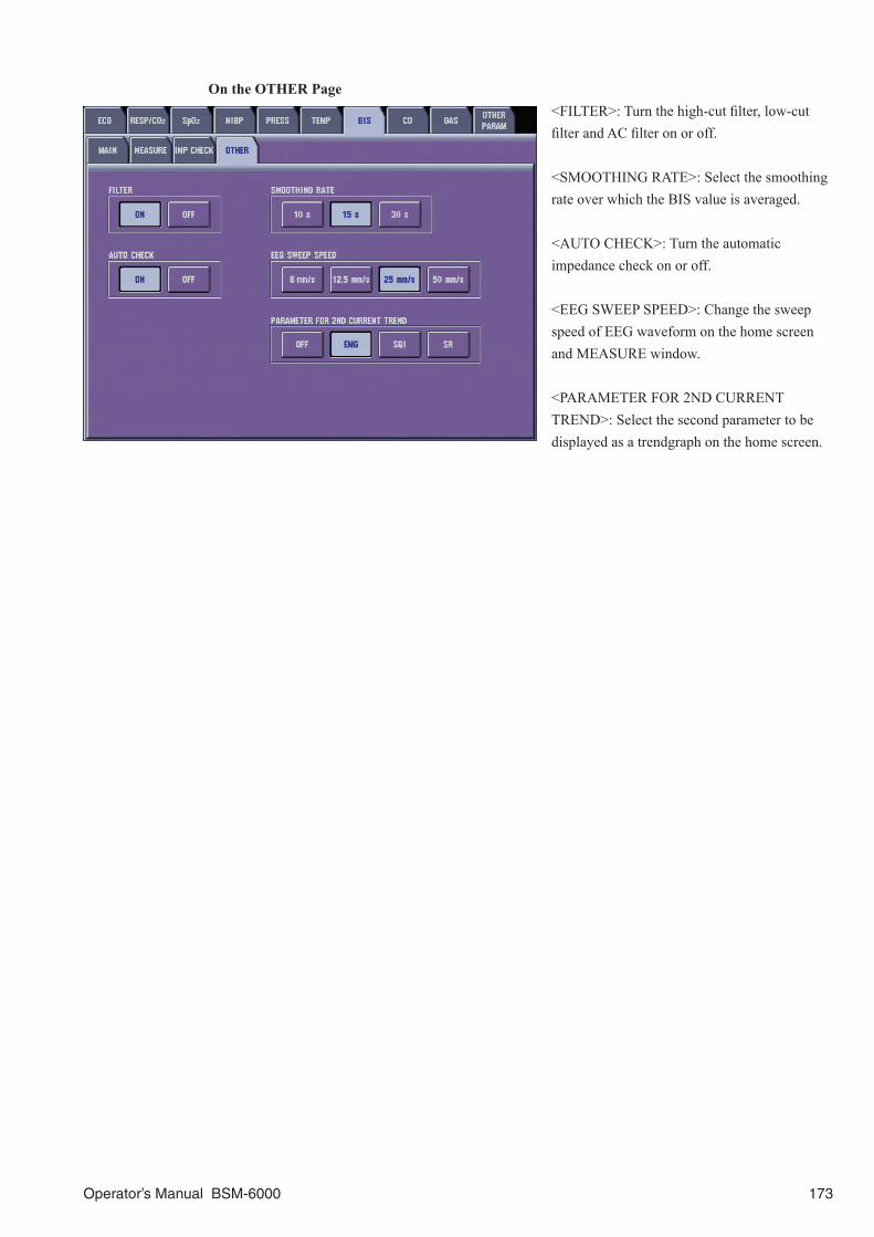
On the OTHER Page<FILTER>: Turn the high-cut filter, low-cut filter and AC filter on or off.
<SMOOTHING RATE>: Select the smoothing rate over which the BIS value is averaged.
<AUTO CHECK>: Turn the automatic impedance check on or off.
<EEG SWEEP SPEED>: Change the sweep speed of EEG waveform on the home screen and MEASURE window.
<PARAMETER FOR 2ND CURRENT TREND>: Select the second parameter to be displayed as a trendgraph on the home screen.
Operator’s Manual BSM-6000 173

Cardiac OutputCO (Cardiac Output) measurement is performed by connecting the measuring system to the MULTI socket on unit. This monitor uses the thermodilution method.
WARNINGWhen performing defibrillation during cardiac output monitoring, never touch the CO
connection cord. The discharged energy may cause electrical shock or injury.
NOTE:
• CO monitoring using the MULTI socket does not comply with the Defibrillator proof type CF.
• The MULTI socket on the AY-660P input unit cannot be used for CO monitoring.
Preparation
Select the appropriate catheter according to the purpose. The following illustrates a typical measuring system setup. For details, refer to the instruction manual of the measuring kit.
When using the Argon Medical Devices Catheter TC-704 and measuring with the in-line sensor method
CO connection cord
IBP connection cord
Injectate bottle
IBP transducer
To infusion circuit line
Distal (PA) lumen (yellow)Balloon
lumen (red)
Thermistor lumen
Inline sensor
Proximal (CVP)lumen (blue)
Thermistor
Balloon
Distal lumen hole
Thermodilution catheter TC-704
Proximal lumen hole
Container for cooling injectate
Inline iced injectate kit
174 Operator’s Manual BSM-6000

Measuring the Pulmonary Capillary Wedge Pressure
Inserting and Retaining the Catheter in the PatientFor details and precautions on the methods of inserting the catheter, refer to relevant literature and manuals.
WARNING• Insert or remove the catheter from the pulmonary artery as quickly as possible. If it
takes longer than about 10 seconds, pulmonary infarction, pulmonary hemorrhage or
pulmonary artery perforation may occur.
• When inserting or removing the catheter, check the blood pressure waveform on the
monitor, X-ray unit images, and other equipment. Do not depend on the insertion or
removal messages displayed on the monitor.
NOTE:
• Set the label to PAP to monitor the blood pressure for checking the catheter position.
• When inserting the catheter into the patient, monitor the blood pressure waveform and check
the position of the catheter at all times.
• If inserting the catheter takes a long time, the catheter may soften from body heat or there
may be spasm in the vein which makes inserting the catheter more difficult.
• Be careful not to burst the balloon. It may cause embolization. To inflate the balloon, use
carbon dioxide and not air. Inflate the balloon slowly while observing the blood pressure
waveform on the monitor.
• Arrhythmia may occur when the catheter is inserted through the ventricle. Monitor ECG.
1. Quickly insert the catheter to the right atrium and inflate the balloon.
2. While checking the position of the catheter from the pressure waveform on the home screen, push it slowly to the pulmonary artery in the direction of the blood flow.
3. After inserting the catheter to the position where the pulmonary capillary wedge pressure (PCWP) waveform can be obtained, deflate the balloon promptly, and check that the pulmonary artery pressure (PAP) waveform is obtained.
4. After determining the position at which the PCWP waveform is obtained when the balloon is inflated and the PAP waveform is obtained when deflated, retain the catheter in the pulmonary artery.
NOTE: Monitor the pulmonary artery pressure (PAP) waveform while retaining the catheter and
check at all times that the tip of the catheter is at the main branches of the pulmonary artery and
not wedging into a peripheral artery.
Operator’s Manual BSM-6000 175

Entering the PCWP and IBP ValuesEnter the IBP values required for calculating the CO. When the IBP lines are labeled correctly, these values are automatically entered.
1. Touch the ART tab to enter ART mean value, CVP tab to enter CVP mean value, PAP tab to enter PAP value and PCWP tab to enter PCWP. The value appears in the upper part of the window.
You can change the value by moving the
horizontal cursor with your finger or by touching the or key.
You can freeze the waveforms by touching the FREEZE key. When the waveforms are frozen, a vertical cursor appears. You can scroll the waveforms by moving the vertical cursor with your finger or the or keys. To unfreeze the waveforms, touch the FREEZE key again.
2. Touch the SET key. The value is entered into the table on the RESULT page.
Measuring Cardiac Output
When the catheter has been inserted, CO measurements can be performed. Before measurements, the coefficient value of the catheter and patient height and weight must be entered.
Changing Settings for CO MeasurementNOTE: The settings, such as injectate volume and catheter size are necessary for calculating
CO. These settings cannot be changed after measurement.
1. Set the coefficient value on the CATHETER page.
When using a Argon Medical Devices or Edwards Lifesciences (Baxter) catheter, the injectate temperature is automatically measured by this monitor. Enter the manufacturer of catheter, catheter size, injectate volume and injectate temperature.
Manufacture of catheter
Catheter sizeInjection volumeMethod of measuring injectate temperature
176 Operator’s Manual BSM-6000
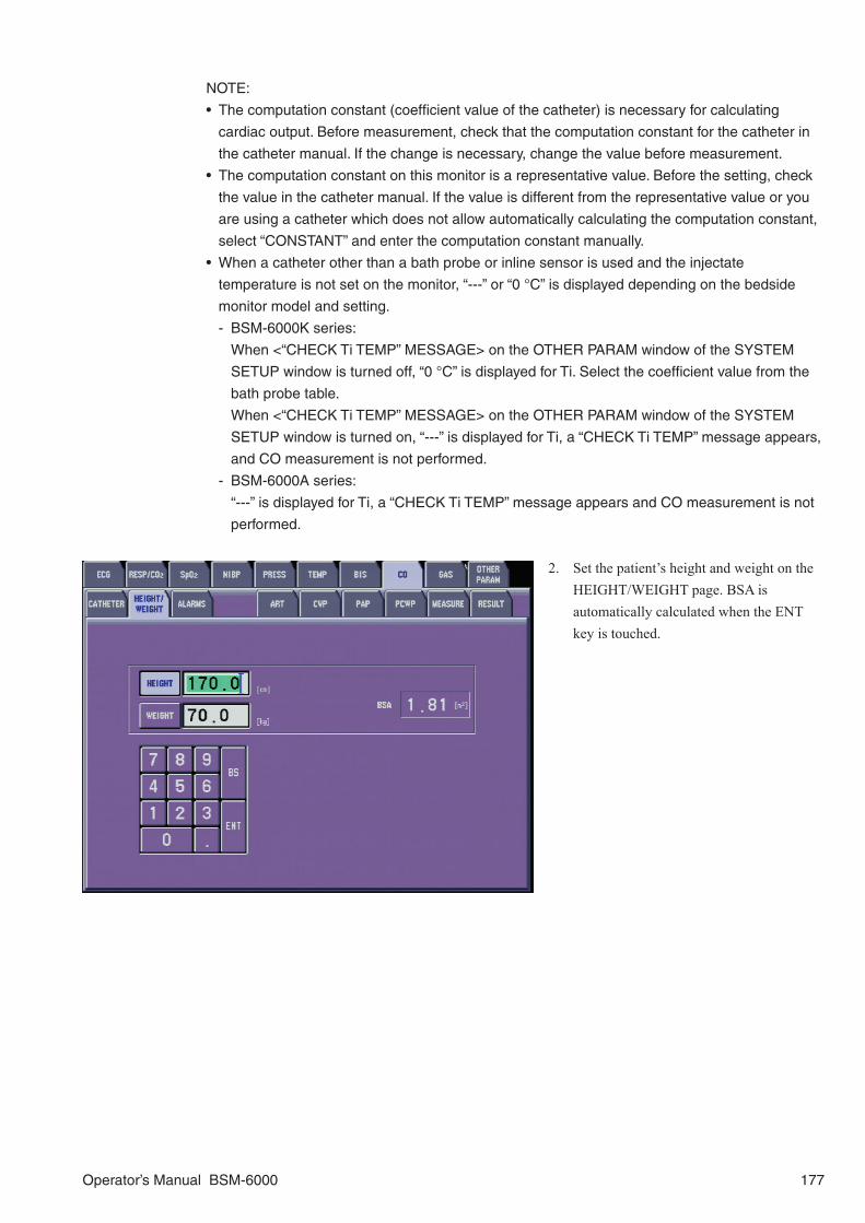
NOTE:
• The computation constant (coefficient value of the catheter) is necessary for calculating
cardiac output. Before measurement, check that the computation constant for the catheter in
the catheter manual. If the change is necessary, change the value before measurement.
• The computation constant on this monitor is a representative value. Before the setting, check
the value in the catheter manual. If the value is different from the representative value or you
are using a catheter which does not allow automatically calculating the computation constant,
select “CONSTANT” and enter the computation constant manually.
• When a catheter other than a bath probe or inline sensor is used and the injectate
temperature is not set on the monitor, “---” or “0 °C” is displayed depending on the bedside
monitor model and setting.
- BSM-6000K series:
When <“CHECK Ti TEMP” MESSAGE> on the OTHER PARAM window of the SYSTEM
SETUP window is turned off, “0 °C” is displayed for Ti. Select the coefficient value from the
bath probe table.
When <“CHECK Ti TEMP” MESSAGE> on the OTHER PARAM window of the SYSTEM
SETUP window is turned on, “---” is displayed for Ti, a “CHECK Ti TEMP” message appears,
and CO measurement is not performed.
- BSM-6000A series:
“---” is displayed for Ti, a “CHECK Ti TEMP” message appears and CO measurement is not
performed.
2. Set the patient’s height and weight on the HEIGHT/WEIGHT page. BSA is automatically calculated when the ENT key is touched.
Operator’s Manual BSM-6000 177

3. Set the upper and lower Tb alarm limits on the ALARMS page.
Measuring COBefore Measurement
Do the following before measurement.1. Completely fill the blood pressure transducer, dome and tubes with physiological saline with heparin
to eliminate air completely.
2. Inject physiological saline with heparin in the CVP lumen of the catheter using a syringe and check that liquid flows out from the tip of the CVP lumen.
3. Fill the PA lumen with physiological saline with heparin.
Check the following before measurement.1. Check the injectate temperature (Ti) on the home screen or CO window.
NOTE: When the injectate temperature is not appropriate, the “Ti OUT OF RANGE”
message appears on the screen and CO cannot be measured.
2. Check that the injectate temperature measurement lines (thermistor probe and in-line sensor) are connected correctly.
NOTE: When a catheter other than a bath probe or inline sensor is used and the injectate
temperature is not set on the monitor, “---” or “0 °C” is displayed depending on the bedside
monitor model and setting.
- BSM-6000K series:
When <“CHECK Ti TEMP” MESSAGE> on the OTHER PARAM window of the SYSTEM
SETUP window is turned off, “0 °C” is displayed for Ti. Select the coefficient value from the
bath probe table.
When <“CHECK Ti TEMP” MESSAGE> on the OTHER PARAM window of the SYSTEM
SETUP window is turned on, “---” is displayed for Ti, a “CHECK Ti TEMP” message
appears, and CO measurement is not performed.
- BSM-6000A series:
“---” is displayed for Ti, a “CHECK Ti TEMP” message appears and CO measurement is
not performed.
178 Operator’s Manual BSM-6000

3. Check the catheter settings on the CATHETER page of the CO window.
NOTE: The settings, such as injectate volume and catheter size are necessary for
calculating CO. These settings cannot be changed after measurement.
Measuring CO
CAUTIONDo not measure the cardiac output repeatedly at short intervals. Frequently injecting the
injectate affects the measuring accuracy.
1. On the MEASURE page, check that the “INJECT” message is displayed and inject the injectate quickly within 4 minutes. CO measurement starts.
NOTE:
• If the injectate is not injected within
4 minutes, the “INJECTION TIME
OUT” message appears. In this
case, touch the MANUAL key on the
MEASURE window and inject the
injectate within 30 seconds.
• Inject the injectate as quickly and
steadily as possible. Measurement
cannot be performed correctly if
injected slowly.
2. Check that the “MEASURING CO” message is displayed on the CO window.
NOTE: The monitor has not acknowledged the injection if the “MEASURING CO” message is
not displayed on the CO window within about 10 seconds after the injectate has been injected.
Inject the injectate again.
When the CO value is calculated, the measurement results are displayed in the CO table on the MEASURE page.
NOTE: Do not close the MEASURE page of the CO window before the measurement result is
displayed in the CO table. Otherwise, the measured data will be lost.
Message display area
Operator’s Manual BSM-6000 179

CO table
Cardiac output
Injectate temperature
Blood temperature
Thermodilution curve
Average valuesCardiac index
When the “INJECT” message is displayed on the MEASURE window again, the injectate can be injected again. Up to five measurement data can be stored in memory and displayed in the CO table. If more than five measurements are performed, the oldest data is deleted.
NOTE: To register the CO values to the hemodynamics table, refer to the “Adding the Acquired
Data to the HEMO TREND Page of the TREND Window” section.
When Measurements Cannot be Performed CorrectlyIn some cases, measurements cannot be performed correctly because the baseline moves due to noise or conditions of the patient, such as physiological changes. In such cases, touch the MANUAL key on the MEASURE window and inject the injectate within 30 seconds. The point when the MANUAL key is touched is the start of measurement.
NOTE: If the injectate is not injected within 30 seconds, the “INJECTION TIME OUT” message
appears.
Deleting the Data from the CO Table
Up to five measurement data can be stored and displayed in the CO table on the MEASURE page. Stored data can be deleted from the list.
NOTE: Once data is deleted, it cannot be recovered.
1. On the MEASURE page, select the data to be deleted from the CO table.
2. Touch the DELETE key to delete data. The average is calculated again.
180 Operator’s Manual BSM-6000

Adding the Acquired Data to the HEMO TREND Page of the TREND Window
The acquired CO data can be added to the hemodynamics trend table in the HEMO TREND page of the TREND window. When data is added to the HEMO TREND page, the data disappears from the MEASURE page of the CO window. “- - -” appears on the CO data display area.
On the RESULT window, touch the ADD key. The acquired data is added to the HEMO TREND page.
To display the hemodynamics trend table, touch the SHOW key.
Operator’s Manual BSM-6000 181

GASThe concentration of gases administered to and respired by the patient during anesthesia can be monitored by connecting the AG-920R multigas unit, GF-110PA or GF-210R multigas unit or GF-120PA or GF-220R multigas/flow unit to the multi-link socket on the monitor. To connect the AG-920R multigas unit to the monitor, the QF-904P interface is required.
NOTE: GF-120PA or GF-220R multigas/flow unit is not available for BSM-6000A series.
Carbon dioxide (CO2), nitrous oxide (N2O), oxygen (O2), and any of five anesthetic agents (Halothane, Isoflurane, Enflurane, Sevoflurane and Desflurane) are monitored on a real-time, breath-by-breath basis. The inspiration and expiration phases are detected from the instantaneous CO2 concentration and the respiration rate is counted from these phases. The measured data are displayed on the home screen and can be viewed with reference to other vital sign data.
Preparation
Set up the multigas unit and connect the unit to the patient.
Changing Gas Settings
Change the settings on the GAS window. The following settings can be changed for gas monitoring.• Respiration rate, apnea, CO2, O2, N2O and agent alarm settings• Scale for CO2, O2, N2O and agent waveforms• Sampling rate (when using AG-920R or GF-110PA multigas unit or GF-120PA multigas/flow unit)• Perform air calibration• Displaying gas parameters on the home screen• Gas measurement on or off (when using GF-110PA or GF-210R multigas unit or GF-120PA or
GF-220R multigas/flow unit)
The CO2 unit can be set to mmHg or kPa on the SYSTEM CONFIGURATION screen.
The display color for each gas can be set on the SYSTEM SETUP window.
On the ALARMS PageSet the upper and lower CO2, O2, N2O, anesthetic agent, respiration rate and apnea alarm limits.*1*2
*1 On BSM-6000A series, if <CRISIS VITAL ALARM MANAGEMENT> on the SYSTEM CONFIGURATION screen is turned on and “ALARM PRIORITY” on the SYSTEM SETUP window is set to CRISIS, the alarm settings of RR, APNEA and CO2 (E) are set to the alarm master setting.
*2 On BSM-6000A series, if <ALARM CAP> on the SYSTEM CONFIGURATION screen is turned on, the alarm settings of RR, APNEA and CO2 (E) are affected by the “ALARM CAP” setting.
182 Operator’s Manual BSM-6000

On the SCALE PageSelect the scale for the CO2, O2, N2O and agent waveforms.
The same scale is used on both the home screen and GAS window.
On the SAMPLING PageThis setting is not available when using a GF-210R multigas unit or GF-220R multigas/flow unit.
There is auto mode and manual mode for the sampling rate. The default setting is AUTO.
AUTO: Sampling volume is 200 mL/min when a water trap for adult is connected to the multigas unit. Sampling rate is 100 mL/min when a water trap for neonate is connected to the multigas unit.MANUAL: You can select from 120 to 200 mL/min in 5 mL/min steps when a water trap for adult is connected to the multigas unit.
You can select from 70 to 120 mL/min in 5 mL/min steps when a water trap for neonate is connected to the multigas unit.
If a value outside this range is set, the mode changes to AUTO.
Operator’s Manual BSM-6000 183

On the AIR CAL PageFor stable measurement accuracy, perform gas calibration every year and whenever you suspect the monitor is not reading correctly.
The monitor periodically performs air calibration. Manually perform the air calibration when inappropriate measurement data appears and before performing gas calibration. It takes about 5 seconds (GF-110PA, GF-120PA) or about 60 seconds (GF-210R, GF-220R) for the air calibration to complete.
Touch the CAL key. Calibration is complete when the “CALIBRATING” message disappears.
On the OTHER PageSelect the parameters to display on the home screen from <SELECTABLE ITEMS> box. RR and CO2(E) are always displayed.
CO2(I) display can be turned off independently of other items when LAYOUT page on the SYSTEM window of the SYSTEM SETUP window is set to SIDE + SMALL BOTTOM or SIDE + LARGE BOTTOM.
Gas measurement can be turned off only when using a GF-110PA or GF-210R multigas unit or GF-120PA or GF-220R multigas/flow unit.
184 Operator’s Manual BSM-6000

On the MEASURE PageAfter completing the preparation, gas data and waveforms appear on the screen.
NOTE:
• The gas monitoring starts about
45 seconds (AG-920R, GF-110PA,
GF-120PA) or 1 minute (GF-210R,
GF-220R) after the [MEASURE] lamp on
the multigas unit lights. The measurement
accuracy is guaranteed for about
10 minutes (AG-920R, GF-110PA,
GF-120PA) or 6 minutes (GF-210R,
GF-220R) after the [MEASURE] lamp
lights.
• Inspired and expired values are not
displayed soon after starting monitoring.
These values stabilize after the
respiration rate appears on the screen.
Auto Calibration
Using AG-920R or GF-110PA Multigas Unit or GF-120PA Multigas/Flow UnitThe monitor periodically performs air calibration at the following intervals. Manually perform the air calibration when inappropriate measurement data appears and before performing air calibration. It takes about 5 seconds for the air calibration to complete.5 minutes after power on: 30 to 100 seconds5 to 60 minutes after power on: 2 to 15 minutes1 to 2 hours after power on: 30 minutesMore than 2 hours after power on: 4 hours
Using GF-210R Multigas Unit or GF-220R Multigas/Flow UnitThe monitor performs the air calibration every 2 hours when the multigas unit is in the steady state. Manually perform the air calibration when inappropriate measurement data appears. It takes about 1 minute for the air calibration to complete.
Inspection of Measuring Accuracy
CAUTIONWhen the monitoring value is not appropriate, perform gas calibration. Perform gas
calibration once a year for stable measuring accuracy.
The inspection of measuring accuracy must be performed by qualified service personnel.
Operator’s Manual BSM-6000 185

O2 Preparation
The following items are necessary for O2 monitoring.• Oxygen sensor, 074705• T-shaped adapter, 110774• FiO2 connection cord, JO-900P
CAUTIONThe oxygen sensor must be stored with the detector facing down. If the oxygen sensor is
not stored with the detector facing down, the oxygen sensor must be left with the detector
facing down for a few minutes before calibration. If the calibration is performed right after
the oxygen sensor has been stored with the detector not facing down, calibration cannot be
performed properly.
NOTE: The MULTI sockets on the AY-660P input unit and BSM-1700 series bedside monitor
cannot be used for monitoring O2.
Connect the oxygen sensor to the FiO2 connection cord and FiO2 connection cord to the MULTI socket.
Calibrating the O2 SensorBefore attaching the oxygen sensor to the patient’s inspiration circuit, calibrate the oxygen sensor.
Calibration can be performed in two ways: calibration with air and calibration with 100% O2 gas. Both methods are performed on the O2 window.• Calibration with air (21% O2)
1. Leave the oxygen sensor in the atmosphere for more than 1 minute.2. Display the MAIN page of the O2 window. Press the [Menu] key → O2 key → MAIN tab.3. Touch the AIR CAL key.4. When the “EXPOSE SENSOR TO AIR” message is displayed, touch the YES key to start
calibration. When the calibration is complete, the calibration date and time, and the O2 value “21” are displayed on the O2 window.
• Calibration with 100% O2
1. Apply 100% O2 flow to the oxygen sensor for more than 1 minute.2. Display the MAIN page of the O2 window.3. Touch the O2 CAL key.4. When the “FLOW CALIBRATION GAS” message is displayed, touch the YES key to start
calibration. When the calibration is complete, the calibration date and time, and the O2 value “100” are displayed on the O2 window.
186 Operator’s Manual BSM-6000

After calibration, attach the oxygen sensor to the patient’s inspiration circuit. Connect the T-shaped adapter to the inspiration circuit of the respirator, with the detector of the oxygen sensor facing down and the oxygen sensor at an inclination angle within 45° from the respirator vertically.
NOTE:
• Connect the detector of the oxygen sensor facing down. Otherwise, the oxygen sensor
function deteriorates and considerable errors in the measured value may occur.
• Do not connect the oxygen sensor where inspiration and expiration gas mix. The oxygen
sensor cannot respond to each respiration.
Changing O2 Settings
Change the alarm settings on the O2 window.
The O2 data display color can be set on the SYSTEM SETUP window.
On the MAIN WindowO2 alarm limits: Set the upper and lower O2 alarm limits.
Operator’s Manual BSM-6000 187

CCOCCO monitoring can be performed by using the JP-600P APCO/IBP processor.
NOTE: The JP-600P APCO/IBP processor is not available for BSM-6000A series.
Preparation
Select the appropriate FloTrac sensor according to the purpose.
Connect the FloTrac sensor to the JP-600P APCO/IBP processor and JP-600P APCO/IBP processor to the MULTI socket.
NOTE: The MULTI socket on the AY-660P input unit cannot be used
for monitoring CCO.
On the MEASURE PageDisplays the CCO data.
Displays the hemodynamics table on the HEMO TREND Page of the TREND Window
188 Operator’s Manual BSM-6000

Changing the CCO Settings
When using the JP-600P APCO/IBP processor, the following settings can be changed for CCO monitoring. Change the settings on the CCO window.• Enter the patient’s date of birth, gender, height and weight• Perform zero calibration• CCO and CCI alarm limits• Scale for AP waveform• Displaying CCO parameters on the home screen• CCO/CCI average time• Displaying CCO or CCI for current trendgraph on the home screen
The display color for CCO can be set on the SYSTEM SETUP window.
NOTE: The blood pressure label is fixed to ART when a JP-600P APCO/IBP processor is used.
On the PATIENT INFO PageEnter the patient information when the patient information is not entered.
NOTE:
• When the date of birth, gender, height
and weight are not entered, CCO
monitoring cannot be performed.
• When the BSA is outside the range of
0.08 to 5.02 m2 and the age is outside
the range of 2 to 120 years old, CCO
monitoring is not available.
On the MAIN Page<ZERO CALIBRATION>Touch the ZERO CAL key to perform zero balance adjustment. When the “ZEROING COMPLETE” message is displayed, zero balance adjustment is complete.
<ALARMS>CCO and CCI alarm limits: Set the upper and lower CCO and CCI alarm limits.
Operator’s Manual BSM-6000 189

On the WAVEFORM PageSelect the scale for the AP waveform.
On the OTHER Page<NUMERIC DISPLAY>: Select the parameter to be displayed in the selected area from the <SELECTABLE ITEMS> box.
<PARAMETER FOR CURRENT TREND>: Select the parameter to be displayed as a trendgraph on the home screen.
<AVERAGE TIME>: Select the averaging time for CCO and CCI display.
Records AP waveform and CCO data of the selected time period on the WS-671P recorder module
190 Operator’s Manual BSM-6000

Other ParametersThe following parameters can be monitored on a BSM-6301, BSM-6501 or BSM-6701 bedside monitor when optional units and connection cables are installed.
WARNINGWhen connecting an external instrument using an interface or communication cable to the
monitor, some alarms and messages from the external instrument might not be displayed
on the monitor. When the waveform or data is abnormal, check the alarm and message on
the external instrument.
CO2 SidestreamCO2 monitoring in sidestream method is available with an AG-400R CO2 unit.
NOTE: AG-400R CO2 unit is not available for BSM-6000A series.
CO2 monitoring in sidestream method is available with a Oridion Microcap® portable bedside monitor or Covidien Microstream® Micropod™ capnography module.
NOTE: Oridion Microcap® portable bedside monitor is not available for BSM-6000K series.
WARNINGAlarms are set on the bedside monitor and external instrument individually. When an alarm
setting is changed on one instrument, the same setting change is not automatically applied
to the other instrument.
BISBIS monitoring is available with a Covidien BIS monitor.
GasGas monitoring is available with an AG-920R, GF-110PA or GF-210R multigas unit or GF-120PA or GF-220R multigas/flow unit.
NOTE: GF-120PA or GF-220R multigas/flow unit is not available for BSM-6000A series.
AnesthesiaAnesthesia gas and ventilation monitoring is available with a Heinen + Löwenstein anesthesia machine, Dräger Medical anesthesia workstation, GE Healthcare anesthesia delivery system, Air Liquide anesthesia system, MAQUET FLOW-i anesthesia system or ACOMA Medical Industry anesthesia apparatus.
NOTE: Heinen + Löwenstein anesthesia machine and ACOMA Medical Industry anesthesia
apparatus are not available for BSM-6000A series.
VentilatorVentilator monitoring is available with Dräger ventilators, Covidien Puritan Bennett ventilators, MAQUET ventilators, Hamilton Medical ventilators, Newport Medical ventilators or CareFusion ventilators.
TOFTOF monitoring is available with a Merck & Co./MSD TOF-Watch® SX neuromuscular transmission monitor.
Operator’s Manual BSM-6000 191

CCOCCO monitoring is available with an Edwards Lifesciences oximeter/continuous cardiac output measuring device, Edwards Lifesciences clinical platform or LiDCO hemodynamic monitor.
PCCOPCCO monitoring is available with a Pulsion Medical Systems PiCCO monitor.
CAUTIONConnect the PiCCO monitor to the BSM-6000 series bedside monitor using only the QF-
911P interface. Do not connect the instruments using any other interface or cable.
Otherwise, the measurement accuracy becomes out of range.
CCO/SvO2
CCO/SvO2 monitoring is available with an ICU Medical oxygen saturation and continuous cardiac output monitor.
Analog InputAnalog waveforms of an external device which outputs analog voltage signal, such as Transonic Systems HT series flowmeters, can be displayed on the monitor screen.
FLOW/PawFLOW/Paw monitoring is available with a GF-120PA multigas/flow unit.
NOTE: GF-120PA and GF-220R multigas/flow unit is not available for BSM-6000A series.
EEGEEG monitoring is available with a AE-918P neuro unit.
WARNINGWhen using the JE-905P EEG connection cord,
bundle all unused electrode leads. When using the
JE-906P EEG connection cord, disconnect all
unused electrode from the EEG connection cord. If
the unused electrode or electrode lead touches a
metal object or any other conductive parts, the
patient may receive electrical shock.
WARNINGWhen using the JE-906P EEG connection cord
and the bedside monitor is connected to a central
monitor network, EEG values and waveforms are
not output to the central monitor from the bedside
monitor. No data or alarm regarding the EEG data
from the neuro unit are displayed on the central
monitor. Be careful on EEG monitoring when the
bedside monitor is connected to a central monitor
network.WARNING
When abnormal waveforms appear (flat waveform
or a lot of AC interference), remove all electrodes
from the patient and stop using the neuro unit.
CAUTIONDo not use the needle electrodes for more than
one hour as a measurement electrode for the
EEG. When measuring the EEG for over one hour,
use the EEG disk electrode.
CAUTIONNever check the skin-electrode impedance with
the needle electrode inserted in the patient. Failure
to follow this caution causes electrical burn where
electrodes are inserted.
192 Operator’s Manual BSM-6000

tcPO2/tcPCO2
Transcutaneous blood gas monitoring is available with a Radiometer transcutaneous monitor.
rSO2
Regional oxygen saturation monitoring is available with a Covidien cerebral/somatic oximeter.
Operator’s Manual BSM-6000 193

194 Operator’s Manual BSM-6000
Screen Messages
The messages displayed when using this monitor are listed in alphabetical order. Each message is followed by the corresponding cause and countermeasure.
An item with an asterisk (*) in the left column is an alarm.
An item with a dagger (†) in the left column is an alarm which is displayed when <AVAILABLE ALARM TYPES> on the ALARM – DISPLAY/SOUND page of the SYSTEM SETUP window is set to ALL. Refer to Section 3 of the Administrator’s Guide.
NOTE: If the problem cannot be solved after performing the countermeasure, contact your Nihon
Kohden representative.
Screen Message Parameter Possible Cause/Criteria Action
* – – – ALARM All parameters
Alarm concerning the – – – (parameter name) occurred.
Take appropriate action depending on the alarm level. (Displaying the home screen may display the alarm in detail.)
– Bed name INTERBED ALARM
All parameters
Alarm occurred on an interbed bed of the bed name.
Check the data of the alarmed bed on the INTERBED window and remove the cause.
– ACQUIRING PWTT DATA NIBP
Started acquiring data for PWTT measurement.
Monitor ECG and SpO2 and wait until the PWTT mark is displayed on the screen (about one minute).
– ALARM SILENCED All parameters
The [Silence Alarms] key was pressed to silence the alarm.
• When the alarm cause is resolved, the alarm is cleared.
• When the [Silence Alarms] key is pressed during alarm silence, all alarms are resumed.
– ALARMS SUSPENDED
All parameters
The [Silence Alarms] key was pressed before alarm occurrence.
To cancel alarm suspension, press the [Silence Alarms] key again.
– ALARMS SUSPENDED – min
All parameters
The SUSPEND MONITORING key was touched.
All alarms resume when the SUSPEND MONITORING or SUSPEND ALARMS key is touched again during alarm suspension.
The SUSPEND ALARMS key was touched.
– ALL ALARMS OFF All parameters
The BYPASS key or ALL ALARMS OFF key is touched to suspend alarm function.
To resume alarm function, touch the BYPASS or ALL ALARMS OFF key.
– ARRHYTHMIA ANALYSIS OFF ECG
<ARRHYTHMIA ANALYSIS> on the SYSTEM SETUP window is set to OFF.
If arrhythmia analysis is necessary, set <ARRHYTHMIA ANALYSIS> on the SYSTEM SETUP window to ON.
* BATTERY ERROR System Battery problems. Contact your Nihon Kohden representative.
* BATTERY WEAK SystemRemaining battery is less than 25%. Switch to AC power and charge the battery
pack.
*BIS CHECK EXTERNAL DEVICE
BIS (BIS monitor)
The BIS monitor is disconnected from the bedside monitor.
Check the interface connection between the BIS monitor and bedside monitor.

Operator’s Manual BSM-6000 195
Screen Message Parameter Possible Cause/Criteria Action
* BIS CHECK SENSOR
BIS (BIS processor/BISx)
The BIS sensor is detached from the patient.
Attach the BIS sensor to the patient properly.
The BIS sensor is disconnected from the PIC Plus patient interface cable.
Connect the BIS sensor to the PIC Plus patient interface cable properly.
The PIC Plus patient interface cable is disconnected from the BIS processor.
Connect the PIC Plus patient interface cable to the BIS processor properly.
The impedance between the BIS sensor and skin is too high.
Check the BIS sensor attachment and remove the cause. If necessary, replace it with a new one. Use only the specified BIS sensor.
* BIS CONNECTOR OFF
BIS (BIS processor/BISx)
The BIS processor is disconnected from the connection cord or the connection cord is disconnected from the monitor.
Check that the BIS processor is firmly connected to the connection cord and connection cord is firmly connected to the monitor.
– BIS HIGH IMPEDANCE
BIS (BIS processor/BISx)
The impedance between the BIS sensor and skin is too high.
Check the BIS sensor attachment and if necessary, replace it with a new one.
– BIS CHECKING IMPEDANCE
BIS (BIS processor/BISx)
The impedance of the BIS sensor is being checked.
Wait until the impedance check is complete.
* BIS MODULE FAILURE
BIS (BIS processor/BISx)
Faulty BIS processor. Contact your Nihon Kohden representative.
– BIS NOISEBIS (BIS processor/BISx)
Noise interference. Check the BIS sensor attachment. If necessary, replace the sensor with a new one.
* BIS SENSOR ERROR
BIS (BIS processor/BISx)
The BIS sensor failure. Display the BIS window and touch the RESET key after replacing the BIS sensor with a new one.
* BIS SENSOR EXPIRED
BIS (BIS processor/BISx)
BIS sensor is past its expiration date.
Replace the BIS sensor with a new one.
– CANNOT ANALYZE‡ ECG
Noise interference for more than 30 seconds and heart rate cannot be counted and arrhythmia cannot be analyzed.
Remove noise.
* CCO ALARM CCOCCO/SvO2
Alarm occurring on the CCO monitor.
Check the CCO monitor and remove the cause of the alarm.
*CCO CHECK EXTERNAL DEVICE
CCOThe CCO monitor is disconnected from the bedside monitor.
Check the interface connection between the CCO monitor and the bedside monitor.
–CCO CHECK PATIENT INFORMATION
CCO (APCO/IBP processor)
The patient’s gender, age and/or BSA are not entered.
Enter the patient’s gender, age and/or BSA.
The patient’s gender, age and/or BSA are out of range.
Check the patient’s gender, age and/or BSA. Enter the patient information correctly.
‡ When <ARRHYTHMIA ANALYSIS> on the ECG window is set to ON, a “CANNOT ANALYZE” message appears instead of “ECG NOISE”. If the “CANNOT ANALYZE” message is displayed for more than 30 seconds, the message changes to an alarm.

196 Operator’s Manual BSM-6000
Screen Message Parameter Possible Cause/Criteria Action
* CCO CHECK SENSOR
CCO (APCO/IBP processor)
The FloTrac sensor is disconnected from the APCO/IBP processor.
Connect the FloTrac sensor to the APCO/IBP processor.
The specified FloTrac sensor is not used.
Use the specified FloTrac sensor.
The cable or sensor is damaged. Replace the cable or sensor with a new one.
APCO/IBP processor internal system failure.
Contact your Nihon Kohden representative.
* CCO CHECK WAVEFORM
CCO (APCO/IBP processor)
The arterial waveform is not accurate enough for measuring CO.
Check the arterial blood pressure waveform and whether there is a critical low blood pressure or high blood pressure, noise, body movement or overdamping. Check that the FloTrac sensor pressure bag is inflated enough. Check the IBP line and the connection. Check the cable connection.
The arterial waveform is not accurate enough for a long period.The IBP line is not appropriate.The arterial systolic pressure is too high or arterial diastolic pressure is too low.
* CCO CONNECTOR OFF
CCO (APCO/IBP processor)
The APCO/IBP processor is disconnected from the monitor.
Connect the APCO/IBP processor properly. When APCO monitoring is not necessary, press the [Silence Alarms] key to silence the alarm.
The APCO/IBP processor is damaged.
Replace the APCO/IBP processor with a new one.
* CCO MODULE FAILURE
CCO (APCO/IBP processor)
Faulty APCO/IBP processor. Contact your Nihon Kohden representative.
– CCO UNSTABLECCO
(APCO/IBP processor)
The arterial waveform is not accurate enough for measuring CCO.
Check the arterial blood pressure waveform and whether there is a critical low blood pressure or high blood pressure, noise, body movement or overdamping. Check that the FloTrac sensor pressure bag is inflated enough. Check the IBP line and the connection. Check the cable connection.
The IBP line is not appropriate.The arterial systolic pressure is too high or arterial diastolic pressure is too low.The patient’s pulse is getting low.
– CCO ZERO IMBALANCE
CCO (APCO/IBP processor)
Zero balance is not adjusted. Adjust zero balance.
– CCO ZERO UNSTABLE
CCO (APCO/IBP processor)
The circuit is not exposed to air during zero balance adjustment.
Expose the circuit to air and perform zero balance adjustment again.
The pressure of zero balance is unstable.
Reconnect the circuit and perform zero balance adjustment again.
– CCO ZEROING COMPLETE
CCO (APCO/IBP processor)
Zero balance adjustment is complete. —
*CCO SVV: HIGHLY VARIABLE PULSE RATE
SVV(APCO/IBP processor)
The pulse rate changes greatly from the arrhythmia, etc. The SVV value might not be reliable.
––
*† CHECK CO2 CELL
CO2(TG-950P/ 970P/980P)
The respiration circuit has fluid or fluid prevents measurement.
Remove fluid from the respiration circuit and fix the airway adapter to the respiration circuit in the correct direction.The respiration circuit has fluid and
CO2 cannot be measured.
* CHECK INPUT UNIT BATTERY System
The battery pack is not inserted correctly in the BSM-1700 series bedside monitor.
Insert the battery pack into the BSM-1700 series bedside monitor correctly.
* CLOCK IC FAILURE System The clock circuit is damaged. Contact your Nihon Kohden representative.
– CLOSE PAPER MAGAZINE Recording
The recorder door is open. Push the recorder door closed until it clicks.

Operator’s Manual BSM-6000 197
Screen Message Parameter Possible Cause/Criteria Action
– CO BASELINE DRIFT CO
Physiological change. Increase the injectate volume or cool the injectate.
Using a respirator. Adjust the respiration phases.Injection interval is short. Increase the injection interval.Noise interference from external devices.
Place external devices as far as possible from the catheter.
* CO CHECK SENSOR CO
The catheter is not connected to the CO connection cord.
Connect the catheter to the CO connection cord properly.
The catheter is faulty. Replace the catheter with a new one.The CO connection cord is damaged. Replace the CO connection cord with a
new one.
– CO CHECK Ti TEMP♦ CO
The injectate temperature is not measured.
Measure the injectate temperature to monitor CO.
* CO CONNECTOR OFF CO
The CO connection cord is disconnected from the monitor.
Connect the connection cord properly. When CO monitoring is not necessary, press the [Silence Alarms] key to silence the alarm.
The CO connection cord is damaged. Replace the CO connection cord with a new one.
– CO DETECTING BASELINE CO
Searching for the baseline of the blood temperature.
Wait for the baseline of the blood temperature to be detected.
– CO INJECT CO
Injectate is not injected or the monitor does not acknowledge that injectate is injected.
Inject the injectate.The monitor has not acknowledged the injection if the “MEASURING CO” message is not displayed on the CO window even when the injectate is injected. Inject the injectate again.
– CO INJECTION TIME OUT CO
Injectate is not detected within 4 minutes after the “INJECT” message was displayed (or 30 seconds after the MANUAL key is pressed).
Touch the MANUAL key and inject the injectate within 30 seconds.
– CO MEASURING CO CO
Measuring the CO. Wait for the calculation to be completed.
* COMMUNICATION LOSS System
The network cable is disconnected. Connect the network cable properly.The cable or connector is faulty. Replace the cable or connector.The hub or router is faulty. Replace the hub or router.
– CONNECT INPUT UNIT System
The input unit‡ is not connected to the main unit or data acquisition unit and the monitor is not ready for monitoring when the transport function is enabled.
Connect the input unit‡ to the main unit or data acquisition unit and authenticate the patient on the SELECT PATIENT DATA window.
♦ On BSM-6000K series bedside monitor, when <“CHECK Ti TEMP” MESSAGE> on the OTHER PARAM window of the SYSTEM SETUP window is turned off, this message does not appear. Refer to “OTHER PARAM Page” in Section 3 of the Administrator’s Guide.
‡ The “input unit” means the AY-600P series input unit and the BSM-1700 series bedside monitor.

198 Operator’s Manual BSM-6000
Screen Message Parameter Possible Cause/Criteria Action
– CO OUT OF RANGE CO
Calculated a value outside the measuring range.
If the catheter retaining condition is not appropriate, the temperature change becomes small and the CO value may be outside the measuring range. Check the catheter retaining condition and the coefficient value setting.
The coefficient value of the injectate temperature is not specified by the catheter manufacturer.
Make sure the injectate temperature is within the range specified by the manufacturer. For example, when using an Argon Medical Devices catheter, the coefficient values for the injectate temperature between 5 and 18°C are not specified so do not use an injectate temperature between 5 and 18°C.
– CO Tb TEMP ERROR CO
The blood temperature is below 15°C or above 45°C. —
The catheter is faulty. Replace the catheter with a new one.
–CO THERMODILUTION CURVE ERROR
COReturned to the baseline of the thermodilution curve too late.
Use the appropriate injection method.
Possible endocardial shunt. Check the accuracy of the measured value.
– CO Ti TEMP ERROR CO
The injectate is not cooled or the room temperature is above 27°C.
Cool the injectate or decrease the room temperature.
The bath probe or inline sensor is faulty.
Replace the probe or sensor with a new one.
* CO2 APNEA CO2Apnea exceeded the apnea alarm limit. —
– CO2 CAL??
CO2(Mainstreamwith TG-950P/ 970P/980P)
Zero calibration is not performed. Perform zero calibration.
– CO2 CALIBRATING
CO2(Mainstreamwith TG-900P/920P)
Zero calibration is being performed.
—
CO2(Sidestream)
Calibration is being performed. —
– CO2 CAL COMPLETE
CO2(Sidestream)
Calibration is complete. —
– CO2 CAL ERROR CO2(Sidestream)
Calibration failed. Calibrate again. If the problem still occurs, contact your Nihon Kohden representative.
*† CO2 CELL OFF
CO2(TG-970P/ 980P)
The airway adapter is disconnected. Connect the airway adapter to the CO2 sensor.
* CO2 CHANGE ABSORBENT
CO2(Sidestream)
The CO2 absorbent needs to be replaced.
Contact your Nihon Kohden representative.
* CO2 CHANGE ADAPTER
CO2(Mainstream)
The CO2 adapter is damaged. Refer to the CO2 sensor kit manual. If necessary, replace the adapter with a new one.
*CO2 CHECK EXTERNAL DEVICE
CO2 (Microcap®/MicroPod™)
The interface is disconnected from the bedside monitor or external instrument.
Check all cable connections between the external instrument and bedside monitor.
CO2(Sidestream)
The AG-400R CO2 unit is disconnected from the bedside monitor.
Check the interface connection between the AG-400R CO2 unit and bedside monitor.

Operator’s Manual BSM-6000 199
Screen Message Parameter Possible Cause/Criteria Action
* CO2 CHECK SENSOR
CO2(Mainstream)
Insufficient sensor light. Refer to the CO2 sensor kit manual. If necessary, replace the kit with a new one.
* CO2 CONNECTOR OFF
CO2
(Mainstream)
The CO2 sensor kit is disconnected from the monitor.
Connect the CO2 sensor kit properly. When CO2 monitoring is not necessary, press the [Silence Alarms] key to silence the alarm.
The CO2 sensor kit is damaged. Replace the CO2 sensor kit with a new one.
* CO2 DEVICE ERROR
CO2 (Microcap®/MicroPod™)
The external instrument or interface failure.
Contact your Nihon Kohden representative.
Communication error between the external instrument and bedside monitor.
CO2(Sidestream)
CO2 unit failure. Contact your Nihon Kohden representative.
* CO2 LINE BLOCK
CO2 (Sidestream/Microcap®/MicroPod™)
The airway adapter, filterline or exhaust gas tube is clogged and CO2 cannot be measured.
Check that there is no clog in the airway adapter, filterline or exhaust gas tube. If necessary, replace with a new one.Make sure that the filterline is placed above the airway adapter.
* CO2 NO FILTERLINE
CO2 (Sidestream)
The filterline is not connected to the CO2 unit or unspecified tube is connected.
Firmly connect the specified filterline to the CO2 unit.
CO2 (Microcap®/MicroPod™)
The filterline is not connected to the external instrument or unspecified tube is connected.
Firmly connect the specified filterline to the external instrument.
– CO2 PLEASE WAIT CO2 (Sidestream)
Measurement of the sensitivity calibration is complete and calculation is started.
Stop the gas supply and wait for the calculation to complete.
– CO2 PURGING
CO2 (Sidestream/Microcap®/MicroPod™)
Purging to remove clogging of the sampling path.
When the clogging is removed, measurement is possible. If the clogging is not removed, the “CO2 LINE BLOCK” message appears. Refer to the “CO2 LINE BLOCK” message.
* CO2 SENSOR ERROR
CO2 (Mainstream)
CO2 sensor is damaged. Replace the CO2 sensor with a new one.
– CO2 WARMING UP
CO2 (Sidestream)
The CO2 unit is warming up. Measurement is not possible.
Wait for the message to disappear.
CO2
(Microcap®/MicroPod™)
The external instrument is warming up. Measurement is not possible.
– CO2 ZERO CALIBRATING
CO2
(Microcap®/MicroPod™)
Auto zero balance adjustment is being performed.
Wait until zero balance adjustment is complete.
CO2 (Sidestream)
Zero calibration is being performed. Wait for the zero calibration to complete.
– DATA SEND ERROR System
The network cable is not properly connected to the bedside monitor, hub and central monitor.
Connect the network cable to the bedside monitor, hub and central monitor properly and insert and remove the input unit‡ from the bedside monitor.
The network cable is damaged. Replace the network cable with a new one and insert and remove the input unit‡ from the bedside monitor.
The bedside monitor is not registered as a monitored bed on the central monitor.
Register the bedside monitor on the central monitor as a monitored bed and insert and remove the input unit‡ from the bedside monitor.
‡ The “input unit” means the AY-600P series input unit and the BSM-1700 series bedside monitor.

200 Operator’s Manual BSM-6000
Screen Message Parameter Possible Cause/Criteria Action
– ECG AUTO LEAD CHANGE ECG
<AUTO LEAD CHANGE> on the ECG window is set to ON, an electrode of the lead for the first trace was detached for more than 5 seconds and therefore the lead was changed to a stable lead.
Check the electrode attachment.
* ECG CHECK ELECTRODES ECG
The electrode lead is detached from the electrode.
Connect the electrode lead to the electrode firmly.
The electrode cannot be attached firmly to the skin.
Replace the electrode with a new one.
The electrode lead is disconnected from the ECG connection cord.
Connect the electrode lead to the ECG connection cord.
The contact between the lead and electrode is poor.
Clean the electrode lead clip or replace the electrode lead with a new one.
<NUMBER OF ELECTRODES> setting on the ECG window is not correct.
Set the correct settings for <NUMBER OF ELECTRODES>.
The electrode lead is damaged. Replace the electrode lead with a new one.Differential offset voltage at electrodes.
Replace the electrode with a new one.
* ECG CHECK ELECTRODE – – ECG
Problems at the specified electrode. Remove the cause by referring to the “ECG CHECK ELECTRODES” message.
– ECG LEARNING ECGStarted learning QRS for arrhythmia analysis.
Wait for learning to finish.
– ECG LOW mV ECGThe QRS amplitude is too small. Move the electrodes to where the QRS
amplitude is large enough and relearn the ECG.
* ECG MODULE ERROR ECG
Module malfunction. Contact your Nihon Kohden representative.
– ECG NOISE‡ ECG
The baseline is not stable due to respiration or body movement.
Change the electrode position.
EMG noise is superimposed. Change the electrode position to where there is less muscle.
The electrode is pulled by the lead. Put some slack into the electrode lead.The electrode is dry. Replace the electrode with a new one.The contact between the lead and electrode is poor.
Clean the electrode lead clip or replace the electrode lead with a new one.
High electrode impedance. Rub the skin with “skinPure” skin preparation gel.
An electric blanket is used. Use another warming method.Equipment which emits strong electromagnetic interference is nearby. e.g. ESU, cellular phone.
Keep the interference source away from the monitor or turn off the emitter source power.
Equipotential grounding is not acquired.
Connect the equipotential ground terminal on the monitor to the equipotential ground terminal on the wall with the grounding lead.
‡ When <ARRHYTHMIA ANALYSIS> on the ECG window is set to ON, a “CANNOT ANALYZE” message appears instead of “ECG NOISE”. If the “CANNOT ANALYZE” message is displayed for more than 30 seconds, the message changes to an alarm.

Operator’s Manual BSM-6000 201
Screen Message Parameter Possible Cause/Criteria Action
–
ECG PACING(This message appears only when pacing spike detection on the ECG window is set to ON.)
ECG
Paced QRS is detected. When the patient does not have an implanted cardiac pacemaker, set the pacing spike detection to OFF on the ECG window.
An electric blanket is used. Use another warming method.ECG of a neonate is monitored. Set the pacing spike detection to OFF on
the ECG window.
– EEG CALIBRATING EEGThe CAL key on the EEG window is touched to display the calibration waveforms.
—
* EEG CHECK ELECTRODES EEG
The electrode is dry or not attached to the patient.
Attach the electrodes to the patient properly. When using disposable electrodes, replace them with new one.
The electrode lead is disconnected from the EEG connection cord.
Connect the electrode lead to the EEG connection cord.
Contact between the electrode lead clip and electrode is poor (when using disposable electrodes).
Replace the EEG electrode lead with a new one.
The electrode lead is damaged. Replace the electrode lead with a new one.Differential offset voltage at electrodes.
Attach the electrodes to the patient properly. When using disposable electrodes, replace them with new one.
The electrode impedance is too high. Clean the attachment site and attach the electrodes again.
The EEG connection cord is disconnected then connected.
When the EEG connection cord is disconnected and then connected again, this message may appear. Press the [Silence Alarms] key to clear the message.
*EEG CHECK EXTERNAL DEVICE
EEGThe neuro unit is disconnected from the bedside monitor. Check the cable connection between the
units.
– EEG CHECKING IMPEDANCE EEG Checking electrode impedance. —
* EEG CONNECTOR OFF EEG
The EEG connection cord is disconnected from the neuro unit.
Connect the EEG connection cord to the neuro unit. When EEG monitoring is not necessary, press the [Silence Alarms] key to silence the alarm.
The EEG connection cord is damaged.
Replace the EEG connection cord with a new one.
– EEG HIGH IMPEDANCE EEG The electrode impedance is too high. Clean the attachment site and attach the
electrodes again.
– EEG RESETTING BASELINE EEG
The RESET key on the EEG window is touched to return all EEG waveforms to the baseline position.
—
* FLOW APNEA FLOW/Paw Apnea exceeded the apnea alarm limit. —
– FLOW CAL COMPLETE FLOW/Paw Zero calibration is complete. —
– FLOW CAL ERROR FLOW/Paw
There was vibration during calibration and zeroing failed.
If the message appears several times, contact your Nihon Kohden representative.
Nearby device was generating a strong noise during calibration and zeroing failed.

202 Operator’s Manual BSM-6000
Screen Message Parameter Possible Cause/Criteria Action
*FLOW CHECK EXTERNAL DEVICE
FLOW/Paw
Measure switch on the unit is turned off.
Turn on the measure switch on the unit.
The connection cable is disconnected from the monitor.
Check the connection between the unit and the monitor.
An error occurs in the communication between the unit and monitor.
Remove the connection cable from the monitor and connect it again. If the problem still occurs, contact your Nihon Kohden representative.
FLOW/Paw The power cord of the multigas/flow unit is disconnected.
Check that the power cord of the multigas/flow unit is securely connected.
FLOW/Paw <FLOW/Paw MEASUREMENT> on the FLOW/Paw window is OFF.
Set the <FLOW/Paw MEASUREMENT> on the FLOW/Paw window to ON.
* FLOW CONNECTOR OFF FLOW/Paw
Faulty flow tube. Replace the flow tube with a new one.The flow tube is disconnected from the unit.
Connect the flow tube to the unit securely.
* FLOW DEVICE ERROR FLOW/Paw Faulty unit. Contact your Nihon Kohden representative.
– FLOW OUT OF RANGE FLOW/Paw
The measured value is outside the measurable range.
Replace the flow tube and/or flow adapter with a new one. If the problem still occurs, contact your Nihon Kohden representative.
– FLOW ZERO CALIBRATING FLOW/Paw Zero calibration is being performed. Wait for calibration to complete.
– FREEZE All parameters
The waveforms are frozen. To unfreeze the waveforms:• Press any key on the screen• Press any key on the monitor• The waveforms are unfreezed 3 minutes
after freezing
* GAS APNEA GASApnea exceeded the apnea alarm limit. —
– GAS CALIBRATING GASAir or gas calibration is being performed.
Wait for the calibration to complete.
– GAS CAL COMPLETE
GAS(GF-110PA/ 120PA/210R/ 220R)
Air or gas calibration is complete.
—
– GAS CAL ERROR
GAS
The sampling line or exhaust gas tube is clogged.
Check that the sampling line and exhaust gas tube are not bent or clogged. Replace with a new one if necessary and perform the manual or air calibration. If the problem still occurs, contact your Nihon Kohden representative.
Contaminated air due to leaking prevented air calibration.
Check that sampling line and respiration circuit are not leaking. After confirming that there are no leaking, ventilate the air around the unit and perform the manual air calibration. If the problem still occurs, contact your Nihon Kohden representative.
GAS(AG-920RGF-110PA/120PA)
The pressure in the gas cylinder is less than 0.1 MPa.
If the pressure in the gas cylinder is less than 0.1 MPa, replace with a new calibration gas and calibrate again.
Correct gas is not used for calibration.
Check that correct gas is used for calibration.

Operator’s Manual BSM-6000 203
Screen Message Parameter Possible Cause/Criteria Action
*GAS CHECK EXTERNAL DEVICE
GAS
Measure switch on the unit is turned off.
Turn on the measure switch on the unit.
The connection cable is disconnected from the monitor.
Check the connection between the unit and the monitor.
An error occurs in the communication between the unit and monitor.
Remove the connection cable from the monitor and connect it again. If the problem still occurs, contact your Nihon Kohden representative. When using an AG-920R multigas unit, refer to the QF-904P interface manual.
GAS(AG-920RGF-210R/220R)
The power cord is disconnected. Check the power cord is securely connected.
GAS(GF-110PA/ 120PA/210R/ 220R)
<GAS MEASUREMENT> on the GAS window is OFF.
Set the <GAS MEASUREMENT> on the GAS window to ON.
* GAS CHECK SAMPLE LINE
GAS(AG-920R)
The sampling gas inlet on the water trap or sampling gas outlet on the rear panel of the unit is pressurized.
Check that the sampling gas inlet or sampling gas outlet of the unit is not pressurized.
* GAS CHECK WATERTRAP
GASThe water trap is not attached properly. The sampling line is not connected properly.
Make sure that the water trap is securely attached to the unit. Connect the sampling line properly.
GAS(GF-210R/220R)
An unspecified sampling line is used.
Use a specified sampling line.
*GAS CHECK WATERTRAP AND SAMPLE LINE
GAS
The water trap is clogged. Empty the water from the water trap. If the problem still occurs, replace the water trap with a new one.
The sampling line is clogged. Check that sampling line is not bent or clogged. Replace with a new one if necessary.
The exhaust gas tube is clogged. Check that exhaust gas tube is not bent or clogged. Replace with a new one if necessary.
* GAS DEVICE ERROR GAS Faulty unit. Contact your Nihon Kohden representative.
* GAS LINE BLOCK GAS
The water trap is clogged. Empty the water from the water trap. If the problem still occurs, replace the water trap with a new one.
The sampling line is clogged. Check that sampling line is not bent or clogged. Replace with a new one if necessary.
The exhaust gas tube is clogged. Check that exhaust gas tube is not bent or clogged. Replace with a new one if necessary.
* GAS MIXED GAS GAS
Two anesthetic agents are detected at the same time when the vaporizer is changed.
When either agent concentration becomes below 0.2% or alarm silences.
Wrong agent is delivered to the vaporizer.
Contact the anesthetic machine manufacturer.
Two anesthetic agents are detected when two vaporizers operated at the same time.

204 Operator’s Manual BSM-6000
Screen Message Parameter Possible Cause/Criteria Action
– GAS OUT OF RANGE GAS
The measured value is outside the measurable range.
• Check the condition of the patient and anesthetic machine.
• Check the connection of the sampling line and respiration circuit.
• Remove the connection cable from the monitor and connect it again.
If the problem still occurs, contact yourNihon Kohden representative.
The measurement sensitivity has shifted.
Perform gas calibration with the correct gas.
* GAS OVERHEATGAS
(GF-210R/220R)
Faulty fan. Contact your Nihon Kohden representative.
– GAS PURGING GAS(AG-920R)
Purging to remove clogging from the sampling line.
Wait for purging to complete.
– GAS UNSPECIFIED ACCURACY
GAS(AG-920R)
The measured value is outside the accuracy range.
• Check the condition of the patient and anesthetic machine.
• Check the connection of the sampling line and respiration circuit.
• Remove the connection cable from the monitor and connect it again.
If the problem still occurs, contact your Nihon Kohden representative.
The measurement sensitivity has shifted.
Peform gas calibration with the correct gas.
– GAS WARMING UP GAS The unit is still warming up. Wait for warming up to complete.
* HIS SYNC ERROR System
The settings for HL7 are not correct. Set the HL7 settings correctly on the HL7 page in the NETWORK window of the SYSTEM CONFIGURATION screen. Refer to Section 2 of the Administrator’s Guide.
The entered patient ID is not correct. Enter the correct patient ID.
* INPUT UNIT DISCONNECT System
The input unit‡ is disconnected from the main unit or data acquisition unit when the transport function is enabled.
Connect the input unit‡ and authenticate the patient on the SELECT PATIENT DATA window to select the monitoring patient.
* INPUT UNIT FAILURE System
Communication error between the input unit‡ and main unit.
Insert and remove the input unit‡ from the bedside monitor. If the problem is not solved, contact your Nihon Kohden representative
The QM-600P memory unit installed inside the input unit‡ is damaged.The data is sent to a bedside monitor or central monitor which has a different time zone setting and data in the input unit‡ is deleted.
Insert and remove the input unit‡ from the bedside monitor or JA-690PA/694PA data acquisition unit and press the [Silence Alarms] key. Make sure to change the zone setting to the same setting as the other bedside monitors or central monitors.
– INSERT REC PAPER Recording
No recording paper. Load the recording paper.
The recording paper is not loaded correctly.
Correctly load the recording paper.
– INVALID CARD System Invalid SD card is inserted. Only use the Nihon Kohden specified SD card.
‡ The “input unit” means the AY-600P series input unit and the BSM-1700 series bedside monitor.

Operator’s Manual BSM-6000 205
Screen Message Parameter Possible Cause/Criteria Action
–
Lost communication with instruments (such as a central monitor) in the network.
System
<AVAILABLE ALARM TYPES> is set to ALL or <ARRHYTHMIA TYPE> is set to EXTENDED on this monitor and the monitor is connected to the network. One or more instruments in the network have software version which does not support extended arrhythmia and communication is lost.
• Set the <AVAILABLE ALARM TYPES> setting to MAIN to restore communication.
• Set the <ARRHYTHMIA TYPE> setting to STANDARD.
• Upgrade all instruments in the network to the recommended software version.
The <PROTOCOL> is set to 2ND GEN. (BSM-6000A series only)
Set the <PROTOCOL> to 1ST GEN.
– MONITOR OFF (interbed window) System
The instrument which is registered to interbed is turned off.
Check the patient condition and secure the patient safety. Then check that the system has no trouble.The instrument which is registered
to interbed is disconnected from the network.
* MPU MODULE ERROR
All parameters
MPU circuit malfunction. Contact your Nihon Kohden representative.
TEMP
The monitor simulates the temperature signal of 27°C and 37°C inside the monitor. Monitoring this simulated signal periodically (every 128 ms), the monitor self-diagnoses the temperature signal processor part of the monitor. When the monitor could not cover the 0 to 45°C measurement range, a “MPU MODULE ERROR” message is displayed.
* MULTILINK CONFIG ERROR
All parameters
Communication failure between QF series interface or IF series communication cable and monitor.
Contact your Nihon Kohden representative.
* MULTILINK POWER ERROR
All parameters
Multi-link power supply failure. Contact your Nihon Kohden representative.
* NIBP AIR LEAK NIBP
The cuff pressure does not change after inflation even after a certain period of time.
Connect the cuff to the air hose properly.Connect the air hose to the socket properly.
The cuff or air hose is damaged. Replace the cuff or air hose with a new one.
* NIBP CANNOT DETECT PULSE NIBP
The patient’s pulse wave is small. Measure by palpation or the invasive blood pressure method.
The cuff is not wrapped on the patient correctly.
Wrap the cuff around the arm of the patient properly.
*NIBP CHECK INTERVAL SETTING
NIBPNIBP is measured at 1 minute intervals for more than 30 minutes.
Check the patient condition and determine whether to continue measuring NIBP at 1 minute intervals.
* NIBP CONNECTOR OFF NIBP
The air hose is disconnected from the monitor.
Connect the air hose properly. When NIBP monitoring is not necessary, press the [Silence Alarms] key to silence the alarm.
The air hose is damaged. Replace the air hose with a new one.
* NIBP CUFF OCCLUSION NIBP The cuff pressure does not decrease
after measurement has completed.Check that the air hose is not bent or squeezed.
* NIBP HIGH CUFF PRESS NIBP Enormous pressure was applied to
the pressure of the cuff.When measuring an adult, ask the patient not to move too much.
– NIBP INFLATION PRESS LOW NIBP Insufficient cuff inflation pressure. Wait until the cuff pressure rises.

206 Operator’s Manual BSM-6000
Screen Message Parameter Possible Cause/Criteria Action
* NIBP MEAS TIMEOUT NIBP
The measuring time exceeded the specified time due to arrhythmia or noise.
If the cause is arrhythmia, measure by invasive blood pressure measurement.Remove the cause if due to noise.
– INFLATION TIME PASSED NIBP Venous puncture cuff inflation time
is exceeded.Restart venous puncture.
– NIBP MEASURING NIBP NIBP Start venous puncture during NIBP. Finish the NIBP measurement and restart
venous puncture.
* NIBP MODULE ERROR NIBP
Module malfunction. Contact your Nihon Kohden representative.
– NIBP PLEASE WAIT NIBP
Measurement started before the cuff inflation pressure was deflated enough.
Check the cuff pressure before starting measurements.When measuring using the adult cuff: below 15 mmHgWhen measuring using the cuff for neonates: below 3 mmHg
–
NIBP REMEASURING(Remeasurement is automatically performed. If the message still appears, after remeasurement, do the counter actions.)
NIBP
The cuff is not attached to the patient.
Attach the cuff to the patient.
Patient moved during measurement. Wait for the patient to stop moving, then measure again.
Patient’s pulse is too small. Measure by palpation or the invasive blood pressure method.
The cuff is not attached properly. Attach the cuff properly.The cuff size is not appropriate. Check that the cuff of the correct size is
used.Patient’s pulse and heart rate is unstable.
Wait for the patient to relax and stop moving.
*
NIBP SAFETY CIRCUIT RUNNING(When this message is displayed, measurement cannot be performedfor 40 seconds.)
NIBP
The hose is bent. Check that the hose is not bent.The inflation time is too long. Stop measurement.In auto mode measurement, the cuff inflation started before the cuff deflation is complete.
Stop measurement.
* NIBP SYSTOLIC OVER NIBP
The maximum blood pressure exceeded 280 mmHg when using the adult cuff, or 150 mmHg when using the neonate cuff.
Measure by palpation or the invasive blood pressure method.
– NIBP WEAK PULSE NIBP
The patient’s pulse wave is too small.
Measure by palpation or the invasive blood pressure method.
The cuff is wrapped too loosely. Wrap the cuff around the arm properly.The cuff size is inappropriate. Use the appropriate cuff.
– NIBP ZEROING NIBP NIBP zero balance adjustment is being performed.
Do not touch the cuff during zeroing and wait for the message to disappear.

Operator’s Manual BSM-6000 207
Screen Message Parameter Possible Cause/Criteria Action
– O2 CAL?? O2
The oxygen sensor is not calibrated. Calibrate the oxygen sensor.The oxygen sensor has reached the end of its life.
Replace the oxygen sensor with a new one.
The oxygen sensor is not connected properly.
Check the connection of the oxygen sensor, wait for more than 1 minute and then calibrate again. If the problem still occurs, replace the oxygen sensor with a new one.
Calibration is performed when the oxygen sensor is not stable.The calibration mode is not appropriate.
Select the correct calibration mode.
– O2 CALIBRATING O2 Calibrating the oxygen sensor. Wait for the calibration to be connected.
* O2 CONNECTOR OFF O2
The FiO2 connection cord is disconnected from the monitor.
Connect theFiO2 connection cord properly. When O2 monitoring is not necessary, press the [Silence Alarms] key to silence the alarm.
The FiO2 connection cord is damaged.
Replace the FiO2 connection cord with a new one.
* O2 CHECK SENSOR O2
The oxygen sensor is disconnected from the FiO2 connection cord.
Connect the oxygen sensor to the FiO2 connection cord properly.
The FiO2 connection cord is damaged.
Replace the FiO2 connection cord with a new one.
The oxygen sensor is damaged. Replace the oxygen sensor with a new one.
–† OUT OF RANGE‡
CO2(TG-950P/ 970P/980P)
CO2 measurement value exceeds the measurement range. —
* PARAMETER NOT AVAILABLE
All parameters
Connected cord or cable of the parameter is not available on the monitor.
—
*PCCO CHECK EXTERNAL DEVICE
PiCCOThe PiCCO monitor is disconnected from the bedside monitor.
Check the interface connection between the PiCCO monitor and the bedside monitor.
* PRESS CHECK SENSOR IBP
The blood pressure transducer is disconnected from the IBP connection cord.
Connect the blood pressure transducer to the IBP connection cord properly.
Malfunction of the blood pressure transducer.
Replace the blood pressure transducer with a new one.
The IBP connection cord is damaged.
Replace the IBP connection cord with a new one.
* PRESS CONNECTOR OFF IBP
The IBP connection cord is disconnected from the monitor.
Connect the IBP connection cord properly. When IBP monitoring is not necessary, press the [Silence Alarms] key to silence the alarm.
The IBP connection cord is damaged.
Replace the IBP connection cord with a new one.
– PRESS OUT OF RANGE IBP
The measured value is outside the measuring range.
Check the measuring environment.
Malfunction of the blood pressure transducer.
Replace the blood pressure transducer with a new one.
*PRESS THIS LABEL IS ALREADY REGISTERED
IBPMore than one IBP connection cord with the same label are used.
Set another label.
– PRESS ZERO CALIBRATING IBP Zero balance adjustment is
performed.Wait for the zero balance adjustment to complete.
– PRESS ZERO IMBALANCE IBP Zero balance is not adjusted. Adjust the zero balance.
‡ When the TG-950P CO2 sensor kit is used, the “OUT OF RANGE” message might not be displayed depending on the software version of the CO2 sensor kit.
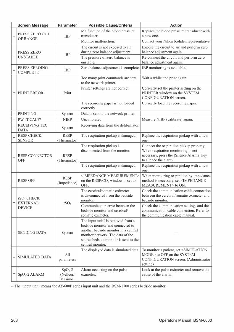
208 Operator’s Manual BSM-6000
Screen Message Parameter Possible Cause/Criteria Action
– PRESS ZERO OUT OF RANGE IBP
Malfunction of the blood pressure transducer.
Replace the blood pressure transducer with a new one.
Monitor malfunction. Contact your Nihon Kohden representative.
– PRESS ZERO UNSTABLE IBP
The circuit is not exposed to air during zero balance adjustment.
Expose the circuit to air and perform zero balance adjustment again.
The pressure of zero balance is unstable.
Re-connect the circuit and perform zero balance adjustment again.
– PRESS ZEROING COMPLETE IBP Zero balance adjustment is complete. IBP monitoring is available.
* PRINT ERROR Print
Too many print commands are sent to the network printer.
Wait a while and print again.
Printer settings are not correct. Correctly set the printer setting on the PRINTER window on the SYSTEM CONFIGURATION screen.
The recording paper is not loaded correctly.
Correctly load the recording paper.
– PRINTING System Data is sent to the network printer. —– PWTT CAL?? NIBP Uncalibrated. Measure NIBP (calibrate) again.
– RECEIVING TEC DATA System Receiving data from the defibrillator. —
* RESP CHECK SENSOR
RESP (Thermistor)
The respiration pickup is damaged. Replace the respiration pickup with a new one.
* RESP CONNECTOR OFF
RESP (Thermistor)
The respiration pickup is disconnected from the monitor.
Connect the respiration pickup properly. When respiration monitoring is not necessary, press the [Silence Alarms] key to silence the alarm.
The respiration pickup is damaged. Replace the respiration pickup with a new one.
– RESP OFF RESP(Impedance)
<IMPEDANCE MEASUREMENT> on the RESP/CO2 window is set to OFF.
When monitoring respiration by impedance method is necessary, set <IMPEDANCE MEASUREMENT> to ON.
*rSO2 CHECKEXTERNAL DEVICE
rSO2
The cerebral/somatic oximeteris disconnected from the bedsidemonitor.
Check the communication cable connectionbetween the cerebral/somatic oximeter andbedside monitor.
Communication error between thebedside monitor and cerebral/somatic oximeter.
Check the communication settings and thecommunication cable connection. Refer to the communication cable manual.
– SENDING DATA System
The input unit‡ is removed from a bedside monitor and connected to another bedside monitor in a central monitor network. The data of the source bedside monitor is sent to the central monitor.
—
– SIMULATED DATA All parameters
The displayed data is simulated data. To monitor a patient, set <SIMULATION MODE> to OFF on the SYSTEM CONFIGURATION screen. (Administrator setting)
* SpO2-2 ALARMSpO2-2
(Nellcor/Masimo)
Alarm occurring on the pulse oximeter.
Look at the pulse oximeter and remove the cause of the alarm.
‡ The “input unit” means the AY-600P series input unit and the BSM-1700 series bedside monitor.

Operator’s Manual BSM-6000 209
Screen Message Parameter Possible Cause/Criteria Action
* SpO2 CANNOT DETECT PULSE
SpO2
(NK)
Poor blood circulation for measuring the SpO2 value.
Check the patient condition, probe attachment or change the attachment site.
The probe is attached too tightly and is obstructing the blood circulation.
Reattach the probe.
The probe is not attached to the patient properly.
Attach the probe to the patient properly.
One of the following message is displayed for 30 seconds.• SpO2 LIGHT INTERFERENCE• SpO2 CHECK PROBE SITE• SpO2 DETECTING PULSE
Refer to the each screen message section and remove the cause of the alarm or message.
SpO2
(Nellcor)The pulse waveform cannot be detected.
Attach the probe to the patient properly.
* SpO2-2 CANNOT DETECT PULSE
SpO2
(NK)
Poor blood circulation for measuring the SpO2 value.
Check the patient condition, probe attachment or change the attachment site.
The probe is attached too tightly and is obstructing the blood circulation.
Reattach the probe.
The probe is not attached to the patient properly.
Attach the probe to the patient properly.
One of the following message is displayed for 30 seconds.• SpO2-2 LIGHT INTERFERENCE• SpO2-2 CHECK PROBE SITE• SpO2-2 DETECTING PULSE
Refer to the each screen message section and remove the cause of the alarm or message.
* SpO2 CHANGE PROBE
SpO2
(NK)
Probe is deteriorated. Replace the probe with a new one.Probe is damaged or short-circuited. Replace the probe with a new one.SpO2 connection cord is damaged. Replace the SpO2 connection cord with a
new one.
SpO2
(Masimo)
The monitor cannot identify the connected probe or the probe is broken.
Replace the probe. Refer to the probe manual.
* SpO2-2 CHANGE PROBE
SpO2
(NK)
Probe is deteriorated. Replace the probe with a new one.Probe is damaged or short-circuited. Replace the probe with a new one.SpO2 adapter is damaged. Replace the SpO2 adapter with a new one.
*SpO2-2 CHECK EXTERNAL DEVICE
SpO2-2 (Nellcor/Masimo)
The pulse oximeter is disconnected from the bedside monitor.
Check the communication cable connection between the pulse oximeter and bedside monitor.
Communication error between the bedside monitor and pulse oximeter.
Check the communication settings and the communication cable connection. Refer to the communication cable manual.

210 Operator’s Manual BSM-6000
Screen Message Parameter Possible Cause/Criteria Action
* SpO2 CHECK PROBE
SpO2
(NK)
The probe is not attached to the patient properly.
Attach the probe to the patient properly.
When the pulse waveform on the screen is flat
The probe cable is disconnected from the SpO2 connection cord or not connected properly.
Connect the probe cable to the SpO2 connection cord.If SpO2 monitoring is not necessary, press the [Silence Alarms] key.
The probe is damaged or short-circuited.
Replace the probe with a new one. If the message still appears, replace the SpO2 connection cord with a new one.
When the pulse waveform is displayed on the screen
The probe is not attached at the appropriate site.
Attach the probe to the appropriate site.
The probe is deteriorated.
Replace the probe with a new one.
SpO2 (Nellcor/Masimo)
The probe is not attached to the patient properly.
Attach the probe to the patient properly.
* SpO2-2 CHECK PROBE
SpO2
(NK)
The probe cable is disconnected from the SpO2 adapter.
Connect the probe cable to the SpO2 adapter.If SpO2 monitoring is not necessary, press the [Silence Alarms] key.
The probe is not attached to the patient properly.
Attach the probe to the patient properly.
The probe is broken or short-circuited.
Replace the probe with a new one. If the message still appears, replace the SpO2 adapter with a new one.
* SpO2 CHECK PROBE SITE
SpO2
(NK)
The probe is not attached at the appropriate site.
Attach the probe to a site 6 to 14 mm thick.
Probe is deteriorated. Replace the probe with a new one.
* SpO2-2 CHECK PROBE SITE
SpO2
(NK)
The probe is not attached at the appropriate site.
Attach the probe to a site 6 to 14 mm thick.
Probe is deteriorated. Replace the probe with a new one.
* SpO2 CONNECTOR OFF
SpO2
(NK/Nellcor/Masimo)
The SpO2 connection cord is disconnected from the SpO2 socket.
Connect the SpO2 connection cord properly. When SpO2 monitoring is not necessary, press the [Silence Alarms] key to silence the alarm.
SpO2
(Nellcor/Masimo)
The probe cable is disconnected from the SpO2 connection cord.
Connect the probe cable to the SpO2 connection cord.If SpO2 monitoring is not necessary, press the [Silence Alarms] key.
SpO2
(Masimo)
The probe is not connected to the patient cable correctly.
Connect the probe to the patient cable with the logo labels facing the same direction.
The monitor cannot identify the connected probe.
Replace the probe. Refer to the probe manual.
* SpO2-2 CONNECTOR OFF
SpO2
(NK)
The probe cable is disconnected from the SpO2 adapter.
Connect the probe cable to the SpO2 adapter.If SpO2 monitoring is not necessary, press the [Silence Alarms] key.
The SpO2 adapter is disconnected from the SpO2 socket.
Connect the SpO2 adapter properly. When SpO2 monitoring is not necessary, press the [Silence Alarms] key to silence the alarm.

Operator’s Manual BSM-6000 211
Screen Message Parameter Possible Cause/Criteria Action
– SpO2 DETECTING PULSE
SpO2
(NK/Nellcor/Masimo)
Searching for the correct pulse wave. Wait until the pulse wave is detected.The probe is not attached to the patient properly.
Attach the probe to the patient properly.
SpO2
(NK)
The SpO2 value cannot be obtained because the waveform is unstable.
Check the probe attachment.
Poor blood circulation for measuring SpO2.
Check the patient condition, probe attachment or change the attachment site.
The probe is secured too tightly and is obstructing the blood circulation.
Reattach the probe.
The probe is disconnected from the SpO2 connection cord.
Connect the probe to the SpO2 connection cord.
The finger probe is not attached to the patient properly.
Attach the finger probe firmly to the patient.
SpO2
(Nellcor/Masimo)
The probe attachment site is not appropriate.
Attach the probe to an appropriate place.
– SpO2-2 DETECTING PULSE
SpO2
(NK)
Searching for the correct pulse wave. Wait until the pulse wave is detected.The probe is not attached to the patient properly.
Attach the probe to the patient properly.
The SpO2 value cannot be obtained because the waveform is unstable.
Check the probe attachment.
Poor blood circulation for measuring SpO2.
Check the patient condition, probe attachment or change the attachment site.
The probe is secured too tightly and is obstructing the blood circulation.
Reattach the probe.
The probe is disconnected from the SpO2 adapter.
Connect the probe to the SpO2 adapter.
The finger probe is not attached to the patient properly.
Attach the finger probe firmly to the patient.
* SpO2-2 ERRORSpO2-2
(Nellcor/Masimo)
There is an error on the pulse oximeter.
Look at the pulse oximeter screen and remove the cause of the error.
* SpO2 LIGHT INTERFERENCE
SpO2
(Masimo)
Too much light on the probe. Remove light or cover the probe site with blanket.
Interference from surroundings. Remove the interference.The probe attachment site is not appropriate.
Attach the probe to an appropriate site.
– SpO2 LOW QUALITY SIGNAL
SpO2
(NK/Nellcor/Masimo)
Considerable body movement. When the message is displayed frequently, check the patient condition and, if necessary, change the attachment site.
The probe is not attached to the patient properly.
SpO2
(Nellcor)
Low signal IQ. When the message is displayed frequently, check the patient condition and, if necessary, change the attachment site.
– SpO2-2 LOW QUALITY SIGNAL
SpO2
(NK)
Considerable body movement. When the message is displayed frequently, check the patient condition and, if necessary, change the attachment site.
The probe is not attached to the patient properly.
* SpO2 MODULE ERROR
SpO2
(NK/Nellcor/Masimo)
SpO2 hardware malfunction. Turn off the monitor power, wait for a few minutes and turn on the power again. If the message still appears, contact your Nihon Kohden representative.
* SpO2-2 MODULE ERROR
SpO2
(NK)
SpO2 hardware malfunction. Turn off the monitor power, wait for a few minutes and turn on the power again. If the message still appears, contact your Nihon Kohden representative.

212 Operator’s Manual BSM-6000
Screen Message Parameter Possible Cause/Criteria Action
* SpO2 NO PROBE SpO2
(NK)The probe is not connected to the SpO2 connection cord.
Connect the probe to the SpO2 connection cord properly.
* SpO2-2 NO PROBE SpO2
(NK)The probe is not connected to the SpO2 connection cord.
Connect the probe to the SpO2 connection cord properly.
– SpO2 WEAK PULSE
SpO2
(NK/Masimo)
Poor peripheral circulation. Check the patient condition and change the attachment site.
The probe is attached too tightly and is obstructing the blood circulation.
Reattach the probe.
SpO2
(Masimo)Low perfusion. Check the patient condition and change the
attachment site.
– SpO2-2 WEAK PULSE
SpO2
(NK)
Poor peripheral circulation. Check the patient condition and change the attachment site.
The probe is attached too tightly and is obstructing the blood circulation.
Reattach the probe.
* tcPO2/PCO2 ALARM tcPO2/PCO2Alarm occurring on the transcutaneous monitor.
Look at the transcutaneous monitor and remove the cause of the alarm.
*tcPO2/PCO2 CHECK EXTERNAL DEVICE
tcPO2/PCO2
The transcutaneous monitor is disconnected from the bedside monitor.
Check the communication cable connection between the transcutaneous monitor and bedside monitor.
Communication error between the bedside monitor and transcutaneous monitor.
Check the communication settings and the communication cable connection. Refer to the communication cable manual.
* TEC DATA RECEIVE ERROR System
Sending data is canceled on the defibrillator. —
Communication distance is too far. Move the defibrillator closer and send data to the bedside monitor again.
Radio waves interference Keep the monitor away from electronic devices which emit strong radio waves.
*TEC INTERFACE ALREADY CONNECTED
SystemTwo QI-670P interfaces are connected.
Remove the most recently connected QI-670P interface from the monitor.
* TEC INTERFACE DISCONNECTED System USB cable of the QI-670P interface
is disconnected from the monitor.Connect the USB cable of the QI-670P interface to the monitor.
* TEC INTERFACE ERROR System
Communication error between the QI-670P interface and monitor.
Reconnect the QI-670P interface to the monitor. If the problem still occurs, contact your Nihon Kohden representative.QI-670P interface error
* TEMP CHECK SENSOR TEMP
The probe is disconnected from the TEMP socket or temperature connection cord is disconnected from the MULTI socket.
Connect the probe to the TEMP socket or the temperature connection cord to the MULTI socket properly.
The probe or temperature connection cord is damaged.
Replace the probe or temperature connection cord with a new one.
The measured value is outside the measuring range.
Check the probe attachment site.
* TEMP CONNECTOR OFF TEMP
The temperature connection cord is disconnected from the monitor.
Connect the temperature connection cord properly. When temperature monitoring is not necessary, press the [Silence Alarms] key to silence the alarm.
The temperature connection cord is damaged.
Replace the temperature connection cord with a new one.
*TEMP THIS LABEL IS ALREADY REGISTERED
TEMPMore than one temperature probe with the same label are used.
Set another label.

Operator’s Manual BSM-6000 213
Screen Message Parameter Possible Cause/Criteria Action
*
– – – THIS PARAMETER IS ALREADY REGISTERED
All parameters
More than the specified number of channels are used for a parameter.
Only use the specified number of channels.
*TOF CHECK EXTERNAL DEVICE
TOFThe TOF-watch® SX is disconnected from the monitor.
Check the interface connection between the TOF-watch® SX and monitor.
* TOF ALARM TOF There is an error on the TOF-watch® SX.
Check the TOF-watch® SX screen and remove the cause of the error.
* TRANSMITTER CONNECTOR OFF System
The connection cord of the transmitter is disconnected from the monitor.
Connect the connection cord properly.
–†
UNSPECIFIED ACCURACY‡
CO2(TG-950P/ 970P/980P)
Temperature or pressure exceeds the operating environment. —
– UPDATING DATA All parameters
Changing the parameter on the trend screen.
Wait until the message disappears.
* VENT ALARM VENT Alarm occurring on the ventilator. Check the ventilator and remove the cause of the alarm.
*VENT CHECK EXTERNAL DEVICE
VENTThe ventilator is disconnected from the monitor.
Check the interface or communication cable connection between the ventilator and the monitor.
‡ When the TG-950P CO2 sensor kit is used, the “UNSPECIFIED ACCURACY” message might not be displayed depending on the software version of the CO2 sensor kit.

214 Operator’s Manual BSM-6000
Troubleshooting
Monitoring
Trouble Possible Cause/Criteria Action
Cannot turn the power on.
The monitor is not connected to the AC outlet.
Connect the monitor to an AC outlet.
Monitor malfunction. Contact your Nihon Kohden representative.The remaining battery power is low. Remove the battery pack and use AC power.
The screen is dark.
The brightness of the screen is not appropriate.
Adjust the setting on the BRIGHT window.
The backlight is old. Contact your Nihon Kohden representative.The monitor is operating on battery. If necessary, set <POWER SAVE MODE> to
OFF on the GENERAL window.
No sync sound.
The sync sound setting is turned OFF. Select the ON button of <SYNC SOUND VOLUME>.
The sync sound volume is turned down. Adjust the volume setting on the VOLUME window.
The sleep mode is turned on. The sleep mode is turned off when:• An alarm occurs.• The touch screen is touched.• Key on the bedside monitor is pressed.
The time displayed on the upper right corner of the screen is not correct.
The date and time setting is not correct. Set the correct date and time on the DATE window.
The backup battery is old. Check the date and time setting on the DATE window and turn the power of the monitor off and on. If the time is incorrect, replace the battery with a new one. Contact your Nihon Kohden representative.
The monitor is too hot. The vent hole is obstructed. Remove the cause.The touch screen keys do not function.
The pressed position and activated position do not match.
Calibrate the touch screen.
The monitor only operates for less than 90 minutes (BSM-6301/ BSM-6501) or 60 minutes (BSM-6701) with a fully charged battery.
The battery pack is old. Replace the battery pack with a fully charged new one.
Some part of the review data is deleted or the time is incorrect.
The monitor was turned off during the system check screen display.
The remaining data may not be reliable. Delete all data.
Three pip sounds and the monitor restarts.
Monitor malfunction. Contact your Nihon Kohden representative.
GF-110PA multigas unit, GF-120PA multigas/flow unit or AE-918P neuro unit is not recognized.
BSM-1700 series bedside monitor is mounted on the BSM-6301 bedside monitor, and GF-110PA multigas unit, GF-120PA multigas/flow unit or AE-918P neuro unit is connected to the multi-link socket.
The combination of BSM-6301 bedside monitor + BSM-1700 series bedside monitor + GF-110PA multigas unit, GF-120PA multigas/flow unit or AE-918P neuro unit is not possible. Replace the BSM-1700 series bedside monitor with an AY-600P series input unit if possible.

Operator’s Manual BSM-6000 215
Network
Trouble Possible Cause/Criteria Action
The monitor cannot be connected to the network.
The network cable is not connected to the monitor properly.
Connect the network cable to the monitor properly.
The network settings are not correct. Set the correct network settings on the NETWORK window of the SYSTEM CONFIGURATION screen.
The monitor is not selected as a monitored bed on the central monitor or receiving instrument.
Select the monitor as a monitored bed on the central monitor or receiving instrument.
Discontinuity in the network cable or faulty hub.
Replace the network cable or the hub with a new one.
The “Lost communication with instruments in the network” message appears on the bedside monitor and the bedside monitor data cannot be monitored on the central monitor.
The <AVAILABLE ALARM TYPES> on the ALARM − DISPLAY/SOUND page of the SYSTEM SETUP window is set to ALL or <ARRHYTHMIA TYPE> on the PARAMETERS window of the SYSTEM SETUP window is set to EXTENDED on the bedside monitor but the central monitor software is old and so the central monitor cannot receive data from this bedside monitor.
To monitor this bedside monitor data on the central monitor, change the <AVAILABLE ALARM TYPES> setting to MAIN. If the bedside monitor still cannot communicate with the central monitor, change the <ARRHYTHMIA TYPE> setting to STANDARD on the bedside monitor.If possible, upgrade the central monitor software.
The <PROTOCOL> on the NETWORK window in the SYSTEM CONFIGURATION screen is set to 2ND GEN. (BSM-6000A series only)
Set the <PROTOCOL> to 1ST GEN.
Transport in a Monitor Network
Trouble Possible Cause/Criteria Action
Cannot display data saved in the input unit* on the destination monitor.
The AY series input unit has no QM-600P memory unit installed.
The QM-600P memory unit must be installed in the AY series input unit to save data.
The data or memory unit in the input unit* is damaged.
Replace the memory unit. Contact your Nihon Kohden representative.
The software version of the main unit is old and the transport function cannot be used.
To use the transport function, the main unit software version must be 02-01 or later.When transporting data with the BSM-9101 bedside monitor, the BSM-9101 software version must be 08-74 or later.
The software versions of the source BSM-6000 series bedside monitor main unit and destination BSM-6000 series bedside monitor main unit are different.
Upgrade both the source and destination BSM-6000 series bedside monitor main units to the same software version. To use the transport function, the main unit software version must be 02-01 or later.Contact your Nihon Kohden representative.
Cannot display waveforms on the full disclosure window.
The source and destination monitors have different parameters to be saved for full disclosure.
Select the same parameters to be saved for full disclosure on the source and destination monitors.
Cannot perform transport function using the central monitor network.
The software versions of the main unit and/or central monitor are old.
Transport function using the network is available with BSM-6000 series bedside monitor software version 02-02 or later and central monitor software version 01-77 or later.

216 Operator’s Manual BSM-6000
Trouble Possible Cause/Criteria Action
Cannot send review data on the HEMO TREND page of the TREND window, RECALL window and 12 LEAD window to the central monitor.
The software versions of the main unit and/or central monitor are old.
To send the review data on the HEMO TREND page of the TREND window, RECALL window and 12 LEAD window, the BSM-6000 series bedside monitor software version must be 02-03 or later and central monitor software version must be 01-77 or later.
Cannot send review data on the ST window to the central monitor.
The software versions of the main unit and/or central monitor are old.
To send the review data on the ST window, the BSM-6000 series bedside monitor software version must be 02-10 or later and central monitor software version must be 01-77 or later.
Cannot display data on the aEEG window on the destination monitor.
Data on the aEEG window cannot be saved in the input unit*1. —
The AF*2 recall data before transport cannot be displayed on the destination bedside monitor.
AF recall data cannot be transported. Check the AF recall data on another bedside monitor on the central monitor.
WLAN transport*2 does not start Central monitors and bedside monitors have different versions.
Upgrade all instruments to the same version.
Incompatible host monitor is connected. Connect a compatible host monitor.WLAN transport is not available on the central monitor which saves the host monitor data.
Save the data in a compatible central monitor.
Transport setting on the host monitor is incorrect.
Set the correct transport settings.
Transport setting on the BSM-1700 series bedside monitor is incorrect.
Set the correct transport settings on the BSM-1700 series bedside monitor.
WLAN transport*2 failed to start <WLAN TRANSPORT> is set to OFF on the BSM-1700 series bedside monitor.
Set the <WLAN TRANSPORT> setting to ON on the BSM-1700 series bedside monitor. Refer to the BSM-1700 bedside monitor administrator’s guide.
Temporary communication error. Disconnect the BSM-1700 series bedside monitor from the host monitor then reconnect it.
The BSM-1700 series bedside monitor is already registered on the central monitor.
Remove the BSM-1700 series bedside monitor bed registration from the central monitor. Refer to the central monitor operator’s manual.
*1 The “input unit” means the AY-600P series input unit and the BSM-1700 series bedside monitor.*2 Not available for BSM-6000K series.
Remote Control
Trouble Possible Cause/Criteria Action
The remote control does not function.
The batteries in the remote control are old.
Replace the batteries with new ones.
Wrong bed is selected. Select the correct remote control channel of the bed.
The display number on the remote control is not correct.
Select the correct display number.
Nothing appears on the display window of the remote control.
The batteries in the remote control are weak.
Replace the batteries with new ones.
LED on the remote control does not blink or light.
The batteries in the remote control are weak.
Replace the batteries with new ones.

Operator’s Manual BSM-6000 217
Recording
Trouble Possible Cause/Criteria ActionThere is no printing (only paper feeding).
The recording paper is upside down. Reload the recording paper into the recorder correctly.
Recorder operates only some of the time.
Dust in the sensor inside the recorder. Clean the surface of the sensor inside the recorder with a dry cotton swab.
Recording is faint.The specified paper is not used. Use the FQW50-2-100 recording paper.The thermal head is dirty. Clean the thermal head with the thermal head
cleaning pen.
Dots are missing. The thermal head is dirty. Clean the thermal head with the provided thermal head cleaning pen.
Recording suddenly starts without key operation.
Alarm recording or periodic recording mode is set to ON.
Set the alarm recording or periodic recording on the RECORD window to OFF if not needed. Press the [Record] key on the monitor to stop recording.
No paper is feeding.The recorder door is open. Push the recorder door closed until it clicks.Dust may have collected in the gears. Contact your Nihon Kohden representative.
Waveforms can be recorded but the trend and list recording cannot.
The recording paper is upside down. Reload the recording paper correctly.Dust in the sensor inside the recorder. Clean the surface of the sensor inside the
recorder with a dry cotton swab.
Printing
Trouble Possible Cause/Criteria Action
The monitor cannot be connected to the network printer.
The network cable is not connected to the monitor properly.
Connect the network cable to the monitor properly.
The printer settings are not correct. Set the correct settings on the PRINTER page of the RECORD window in the SYSTEM CONFIGURATION screen.
ECG
Trouble Possible Cause/Criteria Action
The heart rate is inaccurate.
The QRS amplitude is small. Change the sensitivity so that the QRS amplitude is larger than 1 cm.
The QRS is not detected correctly. Change to a lead which provides good QRS.Change the lead or electrode position so that the QRS is large and T wave is small.
The pacing detection setting on the ECG window is not appropriate.
When the patient does not have an implanted cardiac pacemaker or neonate’s ECG is monitored, set the pacing detection to Off on the ECG window.
The arrhythmia alarm occurs frequently when heart rate is normal.
The dominant QRS is not appropriate for arrhythmia monitoring.
Re-learn the patient ECG or change the dominant QRS.
Patient moved or EMG noise is superimposed.
Change the electrode position to where there is less muscle.
ECG waveform does not appear on the screen when electrodes are attached properly.
<NUMBER OF ELECTRODES> setting on the ECG window is not correct.
Set the correct number for <NUMBER OF ELECTRODES> setting.
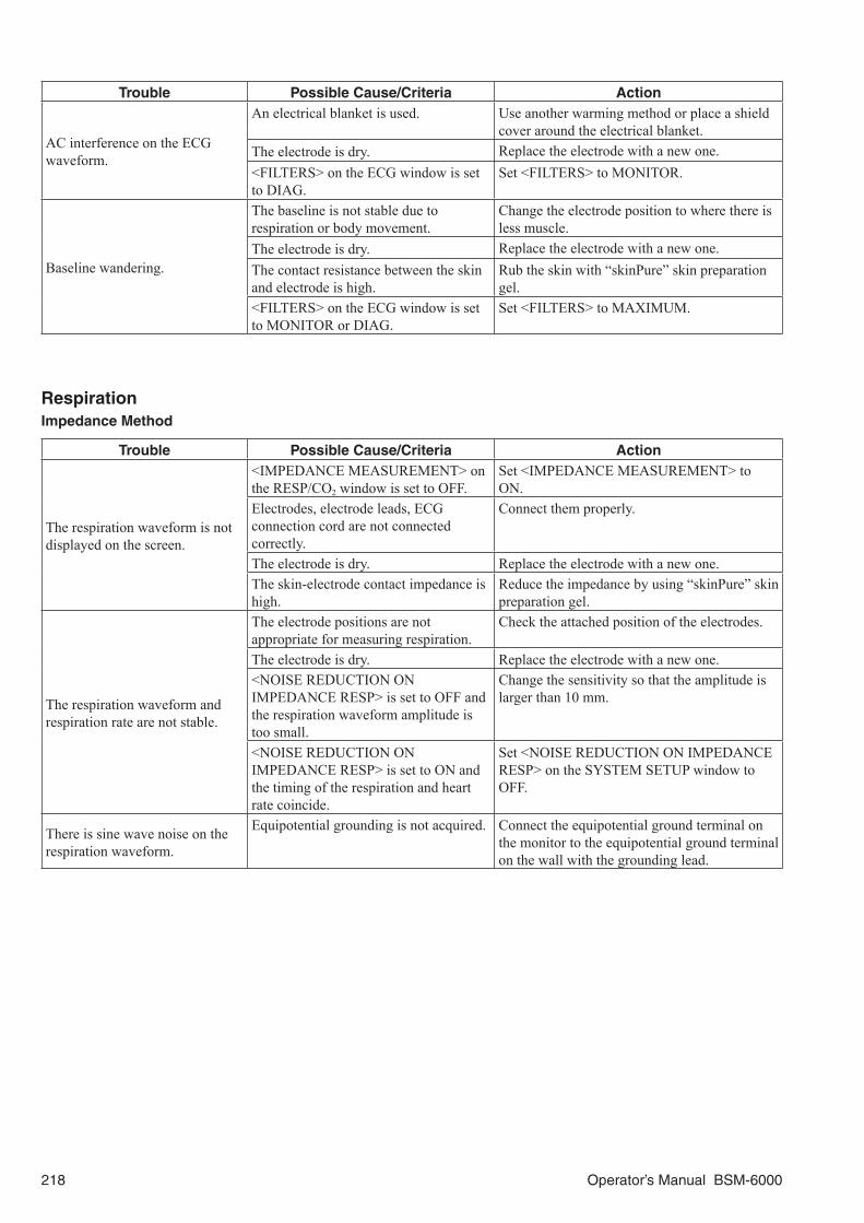
218 Operator’s Manual BSM-6000
Trouble Possible Cause/Criteria Action
AC interference on the ECG waveform.
An electrical blanket is used. Use another warming method or place a shield cover around the electrical blanket.
The electrode is dry. Replace the electrode with a new one.<FILTERS> on the ECG window is set to DIAG.
Set <FILTERS> to MONITOR.
Baseline wandering.
The baseline is not stable due to respiration or body movement.
Change the electrode position to where there is less muscle.
The electrode is dry. Replace the electrode with a new one.The contact resistance between the skin and electrode is high.
Rub the skin with “skinPure” skin preparation gel.
<FILTERS> on the ECG window is set to MONITOR or DIAG.
Set <FILTERS> to MAXIMUM.
RespirationImpedance Method
Trouble Possible Cause/Criteria Action
The respiration waveform is not displayed on the screen.
<IMPEDANCE MEASUREMENT> on the RESP/CO2 window is set to OFF.
Set <IMPEDANCE MEASUREMENT> to ON.
Electrodes, electrode leads, ECG connection cord are not connected correctly.
Connect them properly.
The electrode is dry. Replace the electrode with a new one.The skin-electrode contact impedance is high.
Reduce the impedance by using “skinPure” skin preparation gel.
The respiration waveform and respiration rate are not stable.
The electrode positions are not appropriate for measuring respiration.
Check the attached position of the electrodes.
The electrode is dry. Replace the electrode with a new one.<NOISE REDUCTION ON IMPEDANCE RESP> is set to OFF and the respiration waveform amplitude is too small.
Change the sensitivity so that the amplitude is larger than 10 mm.
<NOISE REDUCTION ON IMPEDANCE RESP> is set to ON and the timing of the respiration and heart rate coincide.
Set <NOISE REDUCTION ON IMPEDANCE RESP> on the SYSTEM SETUP window to OFF.
There is sine wave noise on the respiration waveform.
Equipotential grounding is not acquired. Connect the equipotential ground terminal on the monitor to the equipotential ground terminal on the wall with the grounding lead.

Operator’s Manual BSM-6000 219
Thermistor Method
Trouble Possible Cause/Criteria ActionThe respiration waveform is not displayed on the screen.
Malfunction of the respiration pickup. Replace the respiration pickup with a new one.
The amplitude of the respiration waveform is small or becomes a baseline.
When measuring at the nostrils, the position of the respiration pickup is not appropriate.
Attach the respiration pickup to a position where sufficient temperature changes can be seen.
The respiration pickup for nose is used for measuring a patient with trachea tube inserted.
Measure with a respiration pickup for airway.
The temperature difference between inspiration and expiration is small due to increase in temperature of the inspired air.
Use the impedance method.
The expiration and inspiration phases are reversed.
The inspiration temperature is higher than the expiration temperature.
Use the impedance method.
The respiration rate is not accurate.
The respiration waveform amplitude is too small.
Change the sensitivity so that the amplitude is larger than 10 mm.
CO2 Mainstream Method
Problem Possible Cause/Criteria Action
The measured value is low.
CO2 is mixed in the inspiration. (TG-900P/TG-920P only)
Refer to the CO2 section.
The airway adapter/nasal adapter is dirty.
Replace the adapter with a new one.
The measurement is performed where atmospheric pressure is low, such as at high altitude. (TG-900P/TG-920P only)
Consider the atmospheric pressure when making evaluations.
Zero calibration is not performed. (TG-950P/TG-970P/TG-980P only)
Calibrate the CO2 sensor.
The measured value is high.Anesthetic gas is used.N2O: 2 L/min, sevoflurane: 1%
Set the correct inspired gas composition. Refer to the “On the GAS COMP Page” in CO2 monitoring section.
The measured value is inaccurate.
Oscillation. Check the respirator and remove the cause.Doing suction with a suction catheter in the airway adapter. (TG-900P/TG-920P only)
Do not let the suction catheter in the airway adapter.
A Jackson Rees respiration circuit or Mapleson D respiration circuit is connected to the patient. (TG-900P/TG-920P only)
Cannot measure correctly.
The respiration rate of the patient is very high or respiration is irregular.
Cannot measure correctly.
The respiration waveform does not appear.
Oscillation. Check the respirator and remove the cause.The airway adapter/nasal adapter is disconnected from the CO2 sensor kit.
Connect the adapter to the CO2 sensor kit.
The red LED on the CO2 adapter blinks.
CO2 sensor or CO2 adapter is faulty. (TG-900P/TG-920P only)
Replace the CO2 sensor or CO2 adapter with a new one.
Apnea for longer than 20 seconds. (TG-900P/TG-920P only)
The red LED blinks when apnea is longer than 20 seconds regardless of the alarm setting on the monitor.
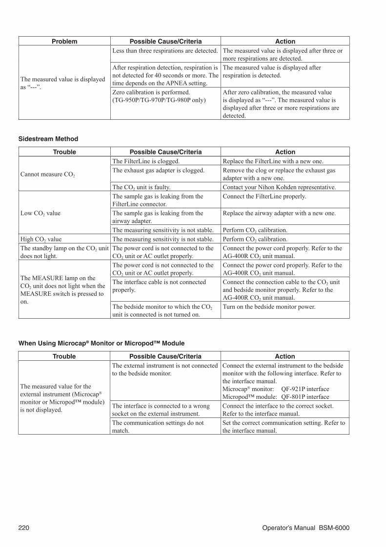
220 Operator’s Manual BSM-6000
Problem Possible Cause/Criteria Action
The measured value is displayed as “---”.
Less than three respirations are detected. The measured value is displayed after three or more respirations are detected.
After respiration detection, respiration is not detected for 40 seconds or more. The time depends on the APNEA setting.
The measured value is displayed after respiration is detected.
Zero calibration is performed. (TG-950P/TG-970P/TG-980P only)
After zero calibration, the measured value is displayed as “---”. The measured value is displayed after three or more respirations are detected.
Sidestream Method
Trouble Possible Cause/Criteria Action
Cannot measure CO2
The FilterLine is clogged. Replace the FilterLine with a new one.The exhaust gas adapter is clogged. Remove the clog or replace the exhaust gas
adapter with a new one.The CO2 unit is faulty. Contact your Nihon Kohden representative.
Low CO2 value
The sample gas is leaking from the FilterLine connector.
Connect the FilterLine properly.
The sample gas is leaking from the airway adapter.
Replace the airway adapter with a new one.
The measuring sensitivity is not stable. Perform CO2 calibration.High CO2 value The measuring sensitivity is not stable. Perform CO2 calibration.The standby lamp on the CO2 unit does not light.
The power cord is not connected to the CO2 unit or AC outlet properly.
Connect the power cord properly. Refer to the AG-400R CO2 unit manual.
The MEASURE lamp on the CO2 unit does not light when the MEASURE switch is pressed to on.
The power cord is not connected to the CO2 unit or AC outlet properly.
Connect the power cord properly. Refer to the AG-400R CO2 unit manual.
The interface cable is not connected properly.
Connect the connection cable to the CO2 unit and bedside monitor properly. Refer to the AG-400R CO2 unit manual.
The bedside monitor to which the CO2 unit is connected is not turned on.
Turn on the bedside monitor power.
When Using Microcap® Monitor or Micropod™ Module
Trouble Possible Cause/Criteria Action
The measured value for the external instrument (Microcap® monitor or Micropod™ module) is not displayed.
The external instrument is not connected to the bedside monitor.
Connect the external instrument to the bedside monitor with the following interface. Refer to the interface manual.Microcap® monitor: QF-921P interfaceMicropod™ module: QF-801P interface
The interface is connected to a wrong socket on the external instrument.
Connect the interface to the correct socket. Refer to the interface manual.
The communication settings do not match.
Set the correct communication setting. Refer to the interface manual.

Operator’s Manual BSM-6000 221
SpO2
Trouble Possible Cause/Criteria Action
Unstable SpO2 value.
The probe size is inappropriate. Use the correct size probe.The probe is attached to the same limb that is used for NIBP or IBP measurement.
Attach the probe to the other limb.
An ESU is used. Locate the ESU as far as possible from the probe and wait until the pulse wave stabilizes.
Measuring on the venous pulse. Cannot measure correctly.
SpO2 value on the monitor and CO oximeter do not match.
The probe is not attached properly. Attach the probe correctly. (The emitter and detector of the probe must face each other.)
The attachment site is inappropriate. Attach the probe to a site 6 to 14 mm thick.The measuring site is not clean. If necessary, remove nail polish and clean the
measuring site.Too much abnormal hemoglobin (HbCO, MetHB, etc.).
Cannot measure correctly.
Dye (methylene blue or indocyanine green) is injected in the blood.
Cannot measure correctly.
Measuring during CPR. Cannot measure correctly.
Probe is damaged.
Probe is disinfected by an unspecified procedure.
Disinfect the probe using the specified method.
The probe is repeatedly used. Replace the probe with a new one when the probe is deteriorated.
Sine wave noise on the pulse wave.
Light interference. Cover the attachment site with a blanket.The line frequency setting on the monitor is not correct.
Set the correct line frequency on the monitor.
No SpO2 data on the screen when using Nellcor probe.
The SpO2 connection cord other than JL-650P is used.
Only the JL-650P SpO2 connection cord can be used with Nellcor probe.
No SpO2 data on the screen when using Masimo probe.
The SpO2 probe and/or connection cord other than specified is used.
Only use the specified SpO2 probe and connection cord.
The probe is not connected to the connection cord correctly.
Connect the probe to the connection cord with the logo labels facing the same direction.
No SpO2-2 data on the screen when using Nihon Kohden probe.
The JL-500P1 or JL-500P2 SpO2 adapter is disconnected from the monitor or probe.
Connect the SpO2 adapter to the monitor and probe.
The MULTI socket on the AY-660P input unit is used for SpO2-2 monitoring.
SpO2-2 cannot be monitored by the MULTI socket on the AY-660P input unit.Use the MULTI socket on the AA-672P or AA-674P smart expansion unit or JA-694PA data acquisition unit.
When Using Nellcor or Masimo Pulse Oximeter
Trouble Possible Cause/Criteria ActionThe SpO2 measured values of the pulse oximeter are not displayed.
The pulse oximeter is not connected to the bedside monitor.
Connect the pulse oximeter to the bedside monitor with the communication cable. Refer to the communication cable manual.

222 Operator’s Manual BSM-6000
NIBP
Trouble Possible Cause/Criteria Action
Cuff inflation pressure is less than 10 mmHg or NIBP data display disappears for a few seconds.
The air hose is not connected to the cuff socket properly.
Connect the air hose to the socket properly.
The cuff is not wrapped around the arm or is wrapped too loosely.
Wrap the cuff around the upper arm.
The cuff does not inflate when the [NIBP Start/Stop] key is pressed.
The cuff hose is not connected to the cuff socket.
Connect the cuff hose to the socket firmly.
The cuff hose or air hose may be folded or squeezed when the cuff pressure display on the screen increases quickly but the actual cuff does not inflate.
Check the cuff hose and air hose.
Abnormal measurement results are displayed.
The cuff size is not correct. Select the cuff which fits the patient’s limb circumference.
The cuff is not wrapped around the arm correctly.
Wrap the cuff around the upper arm, not too tightly or too loosely.
Body movement. Prevent the patient from moving during measurement.
Measurement on the wrong site. Measure NIBP at the correct site.The cuff is suddenly deflated during inflation.
The [NIBP Start/Stop] key is pressed during inflation. —
Auto measurement does not start even when the time interval has passed.
The time interval for the NIBP auto measurement is set incorrectly.
Set the correct time interval.
The cuff suddenly inflates.
The measurement mode is set to auto mode.
Check the time interval.
NIBP measurement is triggered by PWTT.(PWTT is only available on the AY-660P, AY-661P, AY-663P, AY-671P or AY-673P input unit or the BSM-1763 or BSM-1773 bedside monitor and SpO2 is monitored with Nihon Kohden probe.)
Set PWTT on the NIBP window to Off when measuring NIBP with PWTT is not necessary.
Cannot connect cuff to the air hose.
Unspecified cuff is used. Use a cuff specified by Nihon Kohden.
Cannot measure NIBP.
Noise which disables calculation of the blood pressure has interfered.
Remove the cause.
The air hose is bent or squeezed. Remove the cause.The cuff has worn out. Use a new cuff.
Blood congestion occurs. Measuring over a long period of time at intervals less than 2.5 minutes.
Increase the measuring interval.Do not measure NIBP over a long time.
Thrombus occurs.Measuring a patient with known bleeding disorders or a sickle anemia patient.
Do not perform NIBP measurement on such a patient.
NIBP data on the screen is dark or “---” appears.
The time set at <TIME UNTIL DATA IS OLD> on the SYSTEM SETUP window elapsed from the last measurement.
When NIBP is measured again, the data is displayed in normal brightness.

Operator’s Manual BSM-6000 223
IBP
Trouble Possible Cause/Criteria Action
The acquired blood pressure value is different from the estimated value.
Air bubbles remain in the circuit. Remove the air bubbles.An extra tube is connected in the circuit. Remove the extra tube.The position of the blood pressure transducer is inappropriate.
Check the position of the blood pressure transducer.
A blood pressure transducer with different sensitivities is used.
Check the blood pressure transducer.
Other causes. Perform zero balance adjustment again.
No invasive blood pressure value appears on the screen.
The measurement is out of range. Check the measuring condition.The blood pressure transducer is damaged.
Replace the blood pressure transducer with a new one.
No waveform is output from the ECG/BP OUTPUT socket.
IBP is monitored only using the MULTI sockets on the JA-690PAor JS-694PA data acquisition unit.
IBP signal from one of the MULTI sockets is used for BP output.Connect IBP to the MULTI socket for BP output.
The measurement data is displayed as 0 mmHg when the JP-911P IBP connection cord is used.
JP-911P IBP connection cord is damaged.
Replace the JP-911P IBP connection cord with a new one.
Temperature
Trouble Possible Cause/Criteria Action
The temperature value is not displayed on the screen.
The temperature probe or temperature connection cord is faulty.
Replace the temperature probe or temperature connection cord with a new one.
Monitor malfunction. Contact your Nihon Kohden representative.
BISWhen Using BIS Processor/BISx
Trouble Possible Cause/Criteria Action
Nothing appears on the BIS window.
BIS processor or BISx failure. Replace the BIS processor or BISx with a spare if available and contact you Nihon Kohden representative.
When Using BIS Monitor
Trouble Possible Cause/Criteria Action
The measured value for the BIS monitor is not displayed.
The BIS monitor is not connected to the bedside monitor.
Connect the BIS monitor to the bedside monitor with the QF-902P interface. Refer to the QF-902P interface manual.
The interface is connected to a wrong socket on the BIS monitor.
Connect the interface to the correct socket. Refer to the QF-902P interface manual.
The communication settings do not match.
Set the correct communication setting. Refer to the QF-902P interface manual.

224 Operator’s Manual BSM-6000
Cardiac Output
Trouble Possible Cause/Criteria Action
Infarction occurs.
The balloon burst. Remove the catheter from the patient, treat the infarction and insert the new catheter into the patient. Check that the balloon is not damaged before use.
No CO data on the screen.The MULTI socket on the AY-660P input unit is used for CO monitoring.
CO cannot be monitored by the MULTI socket on the AY-660P input unit. Use the MULTI socket on the other unit.
GASWhen Using AG-920R Multigas Unit
Trouble Possible Cause/Criteria Action
The power lamp on the rear panel of the multigas unit does not light.
The power cord is not connected to the multigas unit properly.
Connect the power cord properly. Refer to the AG-920R multigas unit manual.
The power cord is not connected to the AC outlet properly.
The MEASURE lamp on the front panel of the multigas unit does not light.
The power cord is not connected properly.
Connect the power cord properly. Refer to the AG-920R multigas unit manual.
The interface cable is not connected to the multigas unit and main unit of the bedside monitor properly.
Connect the interface properly. Refer to the QF-904P interface manual.
The “Warming up” message does not disappear.
The sampling tube or exhaust gas adapter is bent.
Correct the bent portion and turn on a power supply again.
The water trap or sampling line is kinked or blocked.
Replace with a new one.
The multigas unit is not connected properly.
Connect the sampling gas exhaust outlet of the multigas unit to the scavenging system of the anesthetic machine properly.
The measured value is too low.
The sampling gas is leaking from a sampling tube, airway adapter or water trap.
Check that the water trap or sampling line is connected properly. Replace with a new one if necessary.
The measurement sensitivity has shifted. Perform gas calibration.The measured value is too high. The measurement sensitivity has shifted. Perform gas calibration.
When Using GF-110PA Multigas Unit or GF-120PA Multigas/Flow Unit
Trouble Possible Cause/Criteria Action
The measured value and waveform are not displayed on the screen.
The multi-link cable is not connected to the monitor and multigas/flow unit properly.
Connect the multi-link cable properly.
The software of the monitor does not correspond to the multigas/flow unit.
Contact your Nihon Kohden representative.
The “GAS WARMING UP” message does not disappear.
The sampling tube or exhaust gas tube is bent.
Correct the bent portion and turn on the power supply again.
The water trap or sampling line is kinked or blocked.
Replace with a new one.
The exhaust gas tube is directly connected to an aspirator.
Connect the sampling gas exhaust outlet of the multigas/flow unit to the scavenging system of the anesthetic machine properly.
Multigas/flow unit failure. Contact your Nihon Kohden representative.

Operator’s Manual BSM-6000 225
Trouble Possible Cause/Criteria Action
Gas calibration cannot be done.
Ten minutes have not passed since the power was turned on.
Perform gas calibration when one hour has passed since the power was turned on.
The calibration gas is not flowing. Flow the calibration gas.Multigas/flow unit failure. Contact your Nihon Kohden representative.
The measured density of gas is low.
The sampling gas is leaking from the sampling line or T-piece.
Check that the sampling line or T-piece is connected properly. Replace with a new one if necessary.
When an unspecified sampling line is used, accurate measurement is not possible and the gas may adsorb into the inner wall of the tube.
Use a Nihon Kohden specified sampling line.
The measurement sensitivity has shifted. Perform gas calibaration.
The measured density of gas is high.
When an unspecified sampling line is used, accurate measurement is not possible and the gas may adsorb into the inner wall of the tube.
Use a Nihon Kohden specified sampling line.
The measurement sensitivity has shifted. Perform gas calibaration.Pressure in the gas cylinder is low (less than 0.17 mPa at 200 mL/min) when the sensitivity calibration is done.
Replace with new calibration gas and calibrate again.
Anesthetic gas name displayed on the bedside monitor is different from the actual gas.
Nearby device is generating a strong noise.
Connect the noise-causing device to a different power source than the multigas/flow unit and monitor.Put the multigas/flow unit and monitor and the device that generates strong noise far away from each other.
An unspecified power cord is used. Use a Nihon Kohden specified power cord.The sampling line does not meet specifications.
Replace with a specified sampling line.
Multigas/flow unit failure. Contact your Nihon Kohden representative.
When Using GF-210R Multigas Unit or GF-220R Multigas/Flow Unit
Trouble Possible Cause/Criteria Action
No measured data displayed on the screen.
<GAS MEASUREMENT> on the GAS window is OFF.
Set the <GAS MEASUREMENT> on the GAS window to ON.
The water trap is not attached properly. The sampling line is not connected properly.
Attach the water trap properly. Make sure that the water trap is securely attached to the unit. Connect the sampling line properly.
The flow tube is disconnected from the unit. (GF-220R only)
Connect the flow tube to the unit securely.
The “GAS WARMING UP” message does not disappear.
The unit is still warming up. Wait for the warm up to complete. Warming up takes about 6 minutes.
Unit failure. Contact your Nihon Kohden representative.
“---” is displayed on the screen.
The unit is still warming up. Wait for the warm up to complete. Normally measurement value is displayed on the screen during warming up, “---” may appear due to calibration during warming up.
Zeroing. Wait for the zeroing to complete. “---” is displayed for GAS on the screen during zeroing.
There is an alarm for a faulty unit. Look at the multigas unit and remove the cause of alarm.

226 Operator’s Manual BSM-6000
Trouble Possible Cause/Criteria Action
The measured value of is low.
—Check the measurement accuracy. For details on the measurement accuracy check, refer to the Service Manual.
The sampling gas is leaking from the sampling line or T-piece.
Check that the sampling line or T-piece is connected properly. Replace with a new one if necessary.
An unspecified sampling line is used. Use a Nihon Kohden specified sampling line. When an unspecified sampling line is used, accurate measurement is not possible and the gas may be absorbed into the inner wall of the tube.
Patient’s ventilation conditions are bad. Check the patient’s ventilation conditions. ETCO2 may be less than PaCO2 depending on the patient’s ventilation conditions.
Faulty anesthetic machine. Contact the representative for the anesthetic machine.
The measurement sensitivity has shifted (faulty unit).
Contact your Nihon Kohden representative.
The measured value of gas is high.
—Check the measurement accuracy. For details on the measurement accuracy check, refer to the Service Manual.
An unspecified sampling line is used. Use a Nihon Kohden specified sampling line. When an unspecified sampling line is used, accurate measurement is not possible and the gas may be absorbed into the inner wall of the tube.
Faulty anesthetic machine. Contact the representative for the anesthetic machine.
The measurement sensitivity has shifted (faulty unit).
Perform gas calibration.
Anesthetic gas name displayed on the screen is different from the actual gas.
Nearby device is causing strong noise interference.
Connect the noise-causing device to a different power source than the unit and monitor.Put the unit and the monitor far away from the device that generates noise.
Spray is used around the unit. Ventilate the air in the room.An unspecified power cord is used. Use a Nihon Kohden specified power cord.An unspecified sampling line is used. Use a Nihon Kohden specified sampling line.Faulty unit. Contact your Nihon Kohden representative.
O2
Trouble Possible Cause/Criteria Action
The measured value is abnormal.
The direction of the oxygen sensor changed considerably after calibration.
Face the oxygen sensor downwards and calibrate again.
Peripheral equipment problem. Check the state of the equipment connected to the patient.
The measured value appears “– – –”.
The oxygen sensor is not calibrated. Calibrate the oxygen sensor.The oxygen sensor is deteriorated. Replace the oxygen sensor with a new one.
No O2 data on the screen.The MULTI socket on the AY-660P input unit is used for O2 monitoring.
O2 cannot be monitored by the MULTI socket on the AY-660P input unit. Use the MULTI socket on the other unit.

Operator’s Manual BSM-6000 227
Ventilation
Trouble Possible Cause/Criteria Action
The measured value for the ventilator is not displayed.
The ventilator is not connected to the bedside monitor.
Connect the ventilator to the bedside monitor with the interface or communication cable. Refer to the QF series interface or IF series communication cable manual.
The interface or communication cable is connected to a wrong socket on the ventilator.
Connect the interface or communication cable to the correct socket. Refer to the QF series interface or IF series communication cable manual.
The communication settings do not match.
Set the correct communication setting. Refer to the QF series interface or IF series communication cable manual.
The value is out of display range. Check the measured data on the ventilator screen.
TOF
Trouble Possible Cause/Criteria Action
The TOF measured value is not displayed.
The TOF-watch® SX is not connected to the bedside monitor.
Connect the TOF-watch® SX to the bedside monitor with the QF-909P interface. Refer to the QF-909P interface manual.
CCOWhen Using APCO/IBP Processor
Trouble Possible Cause/Criteria Action
The acquired value is different from the estimated value.
Air bubbles remain in the circuit. Remove the air bubbles.An extra tube is connected in the circuit. Remove the extra tube.The position of the FloTrac sensor is inappropriate.
Check the position of the FloTrac sensor.
APCO/IBP processor and FloTrac sensor are not connected properly.
Connect the APCO/IBP processor and FloTrac sensor properly.
Other causes. Perform zero balance adjustment again.
The measured value for the APCO/IBP processor is not displayed.
The patient’s gender, age and/or BSA are not entered.
Enter the patient’s gender, age and/or BSA.
The patient’s gender, age and/or BSA are out of range.
Check the patient’s gender, age and/or BSA. Enter the patient information correctly.
Zero balance is not adjusted. Adjust zero balance.APCO/IBP processor and FloTrac sensor are not connected properly.
Connect the APCO/IBP processor and FloTrac sensor properly.
The measured value is out of range. Check the measurement condition.The FloTrac sensor is damaged. Replace the FloTrac sensor with a new one.
IBP waveform is not displayed. APCO/IBP processor and FloTrac sensor are not connected properly.
Connect the APCO/IBP processor and FloTrac sensor properly.

228 Operator’s Manual BSM-6000
When Using PiCCO Monitor
Trouble Possible Cause/Criteria Action
The measured value for the PiCCO monitor is not displayed.
The PiCCO monitor is not connected to the bedside monitor.
Connect the PiCCO monitor to the bedside monitor with the QF-911P interface. Refer to the QF-911P interface manual.
The interface is connected to a wrong socket on the PiCCO monitor.
Connect the interface to the correct socket. Refer to the QF-911P interface manual.
The communication settings do not match.
Set the correct communication setting. Refer to the QF-911P interface manual.
When Using Other CCO Monitors
Trouble Possible Cause/Criteria Action
The measured value for the CCO monitor is not displayed.
The CCO monitor is not connected to the bedside monitor.
Connect the CCO monitor to the bedside monitor with the QF-903P interface or IF-922P, IF-946P or IF-948P communication cable. Refer to the QF-903P interface or IF-922P, IF-946P or IF-948P communication cable manual.
The communication cable is connected to a wrong socket on the CCO monitor.
Connect the interface to the correct socket. Refer to the QF-903P interface or IF-922P, IF-946P or IF-948P communication cable manual.
The communication settings do not match.
Set the correct communication setting. Refer to the QF-903P interface or IF-922P, IF-946P or IF-948P communication cable manual.

Operator’s Manual BSM-6000 229
FLOW/PawWhen Using GF-120PA Multigas/Flow Unit
Trouble Possible Cause/Criteria Action
The measured value and waveform are not displayed on the screen.
<FLOW/Paw MEASUREMENT> on the FLOW/Paw window is OFF.
Set the <FLOW/Paw MEASUREMENT> on the FLOW/Paw window to ON.
The flow tube is not connected to the multigas/flow unit properly.
Connect the flow tube properly.
The accuracy of the measured C (Compliance) and R (Airway Resistance) are low.
In the following cases, C and R can not be measured accurately.• Patient with spontaneous breathing.• Auto PEEP is applied.• Flow gas is leaking.
—
The accuracy of the measured flow is low.
The flow gas is leaking from a flow adapter, flow tube or respiration circuit.
Check that the flow adapter, flow tube and respiration circuit are connected properly. Replace with a new one if necessary.
The settings of temperature and humidity are not set on the monitor.
Set the temperature and humidity in the flow adapter.
The settings of gas composition are not set on the monitor.When the anesthetic gas is not monitored at the same time, it is necessary to set the gas composition manually.
Set the gas composition in the flow adapter.
When Using GF-220R Multigas/Flow Unit
Trouble Possible Cause/Criteria ActionThe measured value and waveform are not displayed on the screen.
The flow tube is not connected to the unit properly.
Connect the flow tube properly.
“---” is displayed on the screen. Respiration is not detected. The measurement value is displayed after the 3 breaths are detected.
The accuracy of the measured C (Compliance) and R (Airway Resistance) are low.
In the following cases, C and R cannot be measured accurately.• Patient with spontaneous breathing.• Auto PEEP is applied.• Flow gas is leaking.
—
The accuracy of the measured airway volume is low.
—Check the measurement accuracy. For details on the measurement accuracy check, contact your Nihon Kohden representative.
The flow gas is leaking from a flow adapter, flow tube or respiration circuit.
Check that the flow adapter, flow tube and respiration circuit are connected properly and not leaking. Replace the flow adapter or flow tube with a new one if necessary.
Water droplets are on the flow tube. Replace the flow tube with the new one.The settings of temperature and humidity are not set on the monitor.
Set the temperature and humidity in the flow adapter.
The gas composition are not set on the monitor. When the anesthetic gas is not monitored at the same time, it is necessary to set the gas composition manually.
Set the gas composition in the flow adapter.
Faulty unit. Contact your Nihon Kohden representative.

230 Operator’s Manual BSM-6000
EEGTrouble Possible Cause/Criteria Action
Noise or artifacts superimposed on the waveforms.
The electrode lead is damaged. Check that the electrode leads are not damaged.The Z electrode is not attached to the patient.
Attach the Z electrode.
The 1 and 2 electrodes (JE-906P) or EEG1 (+) and EEG1 (–) electrodes (JE-905P) are not used.
Use the 1 and 2 electrodes (JE-906P) or EEG1 (+) and EEG1 (–) electrodes (JE-905P).
The bed is not grounded. When the bed is metallic, ground it.The monitor is not grounded. Ground the monitor. Make sure that the
provided power cord is used.Several ME instruments are used on the patient.
Perform equipotential grounding.
There is an AC outlet or table tap near the patient or bed.
Arrange the measurement environment so that there is no influence from an AC power line.
A desk lamp or fluorescent light is turned on.
Turn the desk lamp or fluorescent light off.
The patient is touching some metal part. Patient must not touch any metal part.An electric blanket is used. Turn the electric blanket off and use another
warming method.There is a cell phone or radio near the patient.
Turn the cell phone or radio off.
The waveform is not stable.
The Z electrode is not attached to the patient.
Attach the Z electrode to the patient.
The 1 and 2 electrodes (JE-906P) or EEG1 (+) and EEG1 (–) electrodes (JE-905P) are not used.
Use the 1 and 2 electrodes (JE-906P) or EEG1 (+) and EEG1 (–) electrodes (JE-905P).
New and old electrodes or different types of electrodes are used together.
Do not use the new and old electrode or different types of electrodes together. This may cause high polarization voltage.
Sometimes the waveform becomes flat.
The electrodes are not attached to the patient correctly.
Check the electrode attachment. Clean the electrode attachment to reduce impedance.
tcPO2/tcPCO2 Trouble Possible Cause/Criteria Action
The measured value for the transcutaneous monitor is not displayed.
The transcutaneous monitor is not connected to the bedside monitor.
Connect the transcutaneous monitor to the bedside monitor with the IF-913P or IF-914P communication cable. Refer to the IF-913P or IF-914P communication cable manual.
The communication cable is connected to a wrong socket on the transcutaneous monitor.
Connect the communication cable to the correct socket. Refer to the IF-913P or IF-914P communication cable manual.
The communication settings do not match.
Set the correct communication setting. Refer to the IF-913P or IF-914P communication cable manual.
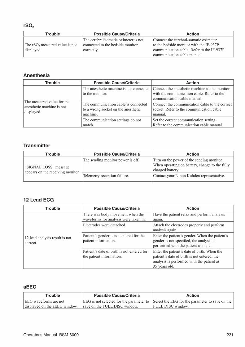
Operator’s Manual BSM-6000 231
rSO2
Trouble Possible Cause/Criteria Action
The rSO2 measured value is not displayed.
The cerebral/somatic oximeter is not connected to the bedside monitor correctly.
Connect the cerebral/somatic oximeter to the bedside monitor with the IF-937P communication cable. Refer to the IF-937P communication cable manual.
AnesthesiaTrouble Possible Cause/Criteria Action
The measured value for the anesthetic machine is not displayed.
The anesthetic machine is not connected to the monitor.
Connect the anesthetic machine to the monitor with the communication cable. Refer to the communication cable manual.
The communication cable is connected to a wrong socket on the anesthetic machine.
Connect the communication cable to the correct socket. Refer to the communication cable manual.
The communication settings do not match.
Set the correct communication setting. Refer to the communication cable manual.
Transmitter
Trouble Possible Cause/Criteria Action
“SIGNAL LOSS” message appears on the receiving monitor.
The sending monitor power is off. Turn on the power of the sending monitor. When operating on battery, change to the fully charged battery.
Telemetry reception failure. Contact your Nihon Kohden representative.
12 Lead ECG
Trouble Possible Cause/Criteria Action
12 lead analysis result is not correct.
There was body movement when the waveforms for analysis were taken in.
Have the patient relax and perform analysis again.
Electrodes were detached. Attach the electrodes properly and perform analysis again.
Patient’s gender is not entered for the patient information.
Enter the patient’s gender. When the patient’s gender is not specified, the analysis is performed with the patient as male.
Patient’s date of birth is not entered for the patient information.
Enter the patient’s date of birth. When the patient’s date of birth is not entered, the analysis is performed with the patient as 35 years old.
aEEG
Trouble Possible Cause/Criteria ActionEEG waveforms are not displayed on the aEEG window.
EEG is not selected for the parameter to save on the FULL DISC window.
Select the EEG for the parameter to save on the FULL DISC window.

232 Operator’s Manual BSM-6000
Maintenance
The bedside monitor contains parts which gradually deteriorate with use. Original performance might not be delivered if any part of the bedside monitor is deteriorated. Perform regular maintenance checks to assure continued safe operation.
CAUTIONBefore maintenance, cleaning or disinfection, turn
the bedside monitor main unit power off and
disconnect the power cord from the AC socket.
Failure to follow this instruction may result in
electrical shock and bedside monitor main unit
malfunction.
CAUTIONIf fluids are accidentally spilled into the monitor,
take the monitor out of service and contact your
Nihon Kohden representative. The monitor must be
disassembled, cleaned, dried and tested for safety
and function.
CAUTIONNever disassemble or repair the monitor. If there is
any problem with the monitor, contact your Nihon
Kohden representative.
CAUTIONDispose of Nihon Kohden products according to
your local laws and your facility’s guidelines for
waste disposal. Otherwise, it may affect the
environment. If there is a possibility that the
product may have been contaminated with
infection, dispose of it as medical waste according
to your local laws and your facility’s guidelines for
medical waste. Otherwise, it may cause infection.
NOTE:
• Refer to the manual for each option for cleaning and disinfecting together with this manual.
• Follow the cleaning and disinfecting procedure in this section.
• Follow the directions of the gas provider for disposal of used calibration gas.
MU-631R, MU-651R and MU-671R Main UnitCleaning and Disinfecting the Main Unit
Before cleaning, turn off the main unit and disconnect the power cord.After cleaning, let dry completely before connecting the power cord and turning on the main unit.
CAUTION• Do not use volatile liquids such as thinner or benzine, because these will cause the
materials to melt or crack.
• The main unit is not waterproof. Be careful not to let any water get inside the main unit.
• Never sterilize the main unit because the materials may deform, crack or discolor.

Operator’s Manual BSM-6000 233
CleaningClean the surface of the main unit every month with a soft cloth moistened with neutral soap, water or alcohol (15°C (75°F), 76.9 to 81.4% by vol), and wipe with a dry cloth or gauze.
Remove dust from the speaker and vent holes on the panels with a cotton swab.
DisinfectingTo disinfect the outside surface of the main unit, wipe it with a non-abrasive cloth moistened with any of the disinfectants listed below. Use the recommended concentration.Disinfectant Concentration (%)Chlorhexidine gluconate solution 0.5Benzethonium chloride solution 0.2Glutaraldehyde solution 2.0Benzalkonium chloride 0.2Alkyldiaminoethylglycine hydrochloride 0.5
Cleaning the Touch Screen
Before cleaning the touch screen, disable touch keys.1. Display the TOUCH KEYS OFF window. Press the [Menu] key → TOUCH KEYS OFF key.
2. Touch the YES key to turn the touchkey function off. Touch the NO key to not turn the touchkey function off.
To turn the touchkey function on again, do any of the following.• Press the [Silence Alarms] key• Press the [NIBP Interval] key• Press the [NIBP Start/Stop] key• Press the [Menu] key• Press the [Home] key• Press the [Record] key
When the touchkey function is turned on by pressing a hard key, the function of that hard key is also performed. For example, if the [NIBP Start/Stop] key is pressed, NIBP measurement in manual mode is performed.
Clean the touch screen using a dry soft cloth or a cloth which is moistened with neutral detergent and wrung out.
Speaker
Vent holes

234 Operator’s Manual BSM-6000
NOTE:
• Do not use a rough cloth.
• Do not use acidic, alkaline detergents or alcohol other than ethanol or isopropyl.
Disposing of the Main Unit
Remove the battery packs when disposing of the main unit. For detailed information about disposal, contact your Nihon Kohden representative.
WS-671P Recorder Module
CAUTION• Do not touch the recording head with any hard object. When the head is tapped with hard
object, the head may crack and the heater element wire may break.
• Clean the head surface with the provided head cleaner pen before loading new paper.
After a period of usage, paper dust may accumulate between the paper and the head
surface and good printing cannot be obtained.
• Be careful not to cut yourself with the paper cutter on the recorder.
Cleaning the Thermal Head
To protect the thermal head from abrasion or damage and assure optimum performance and long service life, clean the surface of the head with the provided thermal head cleaning pen after every 10 to 15 sets of recording paper.
1. Push up the recorder door release lever and open the recorder door.
2. Clean the gold-colored part of the thermal head with the thermal head cleaning pen.
Cleaning the Sensors
The paper empty sensor and mark sensors are located as shown at the left. Clean the sensor surfaces with a cotton swab.
Disposing of the Recorder Module
For detailed information about disposal, contact your Nihon Kohden representative.

Operator’s Manual BSM-6000 235
AY Series Input Unit and AA-672P/AA-674P Smart Expansion UnitCleaning and Disinfecting the Units
Clean and disinfect the units in the same way as cleaning and disinfecting the MU-631R/MU-651R/ MU-671R main unit. Refer to the “MU-631R, MU-651R and MU-671R Main Unit” section.
Disposing of the Units
For detailed information about disposal, contact your Nihon Kohden representative.
BSM-1700 series Bedside MonitorRefer to the manuals of the BSM-1700 series bedside monitor.
SB-671P Battery PackBattery Lifetime
The battery pack can be used for approx. 200 cycles of full discharging/charging or one year whichever comes first.
Replacing the Batteries
Replace the batteries with a new one after 200 cycles of discharging/charging or after one year whichever comes first.
Disposing of Batteries
Before disposing of the batteries, check with your local solid waste officials for details in your area for recycling options or proper disposal. For detailed information about disposal, contact your Nihon Kohden representative.
RY-910P Remote ControllerCleaning and Disinfecting the Remote Controller
Clean and disinfect the remote control in the same way as cleaning and disinfecting the MU-631R/MU-651R/MU-671R main unit. Refer to the “MU-631R, MU-651R and MU-671R Main Unit” section.
Disposing of the Remote Controller
Follow your local laws for disposing of the remote controller.
Replacing the Batteries
Replace the batteries when the batteries are discharged.
Disposing of Batteries
Before disposing of the batteries, check with your local solid waste officials for details in your area for recycling options or proper disposal.
QF series Interface and IF series Communication CableCleaning and Disinfecting the Interface and Communication Cable
Clean and disinfect the interfaces and communication cables in the same way as cleaning and disinfecting the MU-631R/MU-651R/MU-671R main unit. Refer to the “MU-631R, MU-651R and MU-671R Main Unit” section.

236 Operator’s Manual BSM-6000
Disposing of the Interface and Communication Cable
For detailed information about disposal, contact your Nihon Kohden representative.
Leads, Cables and CordsNOTE:
• Do not touch the socket pin.
• Do not wet the socket.
Cleaning the Leads, Cables and Cords
Wipe with a soft cloth moistened with neutral soap, water or alcohol and wipe with a dry cloth or gauze.
Disinfecting the Leads, Cables and Cords
Wipe with a non-abrasive cloth moistened with any of the disinfectants listed below. Use the recommended concentration.Disinfectant Concentration (%)Chlorhexidine gluconate solution 0.5Benzethonium chloride solution 0.2Glutaraldehyde solution 2.0Benzalkonium chloride 0.2Alkyldiaminoethylglycine hydrochloride 0.5
Disposing of Leads, Cables and Cords
For detailed information about disposal, contact your Nihon Kohden representative.
Electrodes, Probes, Cuffs, Thermistors, Transducers, Catheters and Other ConsumablesSee the instructions supplied with the item. Do not reuse disposable items. For detailed information about disposal, contact your Nihon Kohden representative.
Periodic InspectionIf the periodic inspection is not performed, degradation or loss of function may go unnoticed and lead to misdiagnosis.
Service personnel should perform the periodic inspection at least once every year. Make sure that the bedside monitor operates properly and replace the consumables.
If you found abnormalities as a result of inspection and the bedside monitor is suspected to be faulty, attach an “Unusable” or “Repair request” label to the bedside monitor and contact your Nihon Kohden representative. For inspection, refer to the Service Manual.
Check the following items every year to keep your monitor in optimal condition.• Monitor is not dirty, damaged or rusty.• No key or switch is broken.• No damage to the sockets on the monitor.• Power cord is not damaged.• Grounding lead is properly connected.• Screen is clean.• Screen brightness can be adjusted.

Operator’s Manual BSM-6000 237
• Screen display is correct.• Clock is correct.• SYSTEM SETUP settings are correct.• The specified electrodes, sensors, transducers and probes are used.• Recorder (option) operates properly when used.• The specified recording paper is used.• The printed date is correct.• Alarm and sync sound can be heard clearly.• Alarm setting is correct and functions properly.• Alarm indicator lamps light.• The sync sound is produced and sync mark is displayed.• The blood pressure zero balance is performed.• The blood pressure label is attached to the connection cord connector.• The correct values are obtained for invasive blood pressure, CO2 and O2 in the calibration by the
specified mercury manometer and calibration gas.• No current leakage.• Supplied voltage is correct.• Measurement accuracy is within the specified range.• Only the specified parts are used.
Safety Information for Maintenance on Optional Units
AG-920R, GF-110PA or GF-210R Multigas Unit and GF-120PA or GF-220R Multigas/Flow
Unit
CAUTIONBefore maintenance, cleaning or disinfection, turn
the multigas unit power off and disconnect the
power cord from the AC socket. Failure to follow
this instruction may result in electrical shock and
multigas unit malfunction.
CAUTIONWhen the monitoring value is not appropriate,
perform gas calibration. Perform gas calibration
once a year for stable measuring accuracy.
CAUTIONDo not spray detergent or water in the vent hole of
the multigas unit. The operator may receive
electrical shock or the unit may be damaged.
CAUTIONFollow the CAUTION label on the CO2 gas
cylinder.
CAUTIONHandle the contents of the water trap as you would
handle any bodily fluid. Failure to follow this
warning causes infection.
NOTE: Follow the directions of the gas provider for disposal of used calibration gas.

238 Operator’s Manual BSM-6000
AG-400R CO2 Unit
CAUTIONBefore maintenance, cleaning or disinfection, turn
the CO2 unit power off and disconnect the power
cord from the AC socket. Failure to follow this
instruction may result in electrical shock and CO2
unit malfunction.
CAUTIONWhen the monitoring value is not appropriate,
perform gas calibration. Perform gas calibration
every half year for stable measuring accuracy.
CAUTIONDo not spray detergent or water in the vent hole of
the CO2 unit. The operator may receive electrical
shock or the unit may be damaged.
NOTE: Follow the directions of the gas provider for disposal of used calibration gas.
AE-918P Neuro Unit
CAUTIONBefore maintenance, cleaning or disinfection, turn
the instrument power off and disconnect the power
cord from the AC socket. Failure to follow this
instruction may result in electrical shock and
instrument malfunction.
CAUTIONIf fluids are accidentally spilled into the neuro
unit, take the neuro unit out of service and
contact your Nihon Kohden representative. The
neuro unit must be disassembled, cleaned, dried
and tested for safety and function.
CAUTION• Do not use volatile liquids such as thinner or
benzine, because these will cause the materials
to melt or crack.
• The neuro unit and EEG connection cord are not
waterproof. Be careful not to let any water get
inside the neuro unit and EEG connection cord.
• Never sterilize the neuro unit and EEG
connection cord because the materials may
deform, crack or discolor.
Operator’s Manual BSM-6000 239
Specifications
Measuring Parameters
ECG, respiration in impedance and thermistor method, SpO2, NIBP, IBP, temperature, cardiac output, O2, CO2 in mainstream method and sidestream method, flow/Paw, BIS, anesthetic gas (CO2, O2, N2O, agent), TOF, ventilation, CCO, EEG, tcPO2, tcPCO2, rSO2
Influence on Measuring Accuracy by Electrosurgery/Defibrillation/Electrostatic Discharge
The bedside monitor returns to the previous operating mode within 10 seconds without loss of any stored data. When performing defibrillation, the filter setting on the bedside monitor must be set to MONITOR on the ECG window to return to the previous operating mode within 10 seconds without loss of any stored data. Measurement accuracy may be temporarily decreased while performing electro-surgery or defibrillation. This does not affect patient or equipment safety.
Display
Display size: BSM-6301: 10.4 inch, color TFT type LCD BSM-6501: 12.1 inch, color TFT type LCD BSM-6701: 15 inch, color TFT type LCDResolution: BSM-6301/6501: 800 × 600 dots BSM-6701: 1024 × 768 dotsViewing area: BSM-6301: 212.2 mm × 159.4 mm BSM-6501: 246.0 mm × 184.5 mm BSM-6701: 304.1 mm × 228.1 mmWaveform display: ECG (maximum 12 traces), respiration, IBP (maximum 7 traces), SpO2 pulse wave,
CO2 and CO thermodilution curve, EEG, N2O concentration, O2 concentration, anesthetic agent concentration (Halothane, Isoflurane, Enflurane, Sevoflurane, Desflurane), flow, Paw, volume, AP
Waveform display mode: Non-fade moving or non-fade fixedMaximum number of waveform trace: 15 tracesSweep speed: 6.25, 12.5, 25 or 50 mm/sRespiration sweep speed: 1.56, 6.25, 12.5 or 25 mm/sAspect ratio (ECG display sensitivity ratio to sweep speed): Standard: 0.4 s/mV Setting range: 0.05 to 6.4 s/mVSweep time (at 25 mm/s sweep speed): BSM-6301: 6.0 s BSM-6501: 6.5 s BSM-6701: 9.0 sDisplay delay time: DIAG and MONITOR mode: ≤ 250 ms MAXIMUM mode: ≤ 1 sWaveform display color: 12 colorsNumeric data display: Heart rate, VPC rate, ST level, respiration rate, NIBP (systolic, diastolic, MAP),
PWTT, delta PWTT, IBP (systolic, diastolic, mean), SpO2, pulse rate, temperature, cardiac output, cardiac index, injectate temperature, blood temperature, O2 concentration, ETCO2, FiCO2, BIS, inspired/expired N2O concentration, inspired/expired O2 concentration, inspired/expired anesthetic agent concentration

240 Operator’s Manual BSM-6000
(Halothane, Isoflurane, Enflurane, Sevoflurane, Desflurane), minimum alveolar concentration, peak airway pressure, positive end expiratory pressure, mean airway pressure, minute volume, expiratory/inspiratory tidal volume, compliance, airway resistance, expiratory/inspiratory airway resistance, inspiration expiration ratio, inspired setO2, CCO, SVRI, SvO2, Tb, EF, ScvO2, CCI, EDV, SVR, EDVI, PCCO, PCCI, SEF, MDF, PPF, TP, Abs δ, Abs θ, Abs α, Abs β, Abs γ, % δ, % θ, % α, % β, % γ, tcPO2, tcPCO2, PPV, SPV, rSO2
Synchronization mark: Heart rate sync mark, pulse rate sync mark, respiratory sync markNumeric display color: 12 colorsRecovery time after defibrillation: ≤ 10 s (at MONITOR mode)
Alarm
Alarm levels: Crisis: Patient is in critical condition and the patient’s life may be at risk. Immediate action
must be taken. Warning: Patient is in critical condition. Prompt action should be taken. Advisory: Setting or condition is not appropriate for accurate monitoring.Alarm items: Vital sign alarms: HR, PR, ST, RR, APNEA, TEMP, delta TEMP, SpO2, SpO2-2, delta SpO2, NIBP,
IBP, ETCO2, CO2 (I), O2 (I), O2 (E), Tb, MV, Ppeak, PEEP, N2O (I), N2O (E), Agent (I), Agent (E), SEF, TP, BIS, CCO, CCI
Arrhythmia alarms: ASYSTOLE, VF, VT, V BRADY, EXT TACHY, EXT BRADY, SV TACHY, VPC RUN, TACHYCARDIA, BRADYCARDIA, COUPLET, EARLY VPC, MULTIFORM, V RHYTHM, PAUSE, BIGEMINY, TRIGEMINY, VPC, AF*,
IRREGULAR RR, PACER NON-CAPTURE, PROLONGED RR, NO PACER PULSE
* Not available for BSM-6000K series.
Interbed alarms Technical alarms: Alarms concerning instrument and measuring environment such as, connector
disconnection alarm, noise alarm, electrode off alarm, waveform detecting alarm, probe off alarm, cuff/hose check alarm, sensor check alarm, low battery alarm, etc.
Alarm indication*: Alarm sound, blinking/lighting alarm indicator, highlighted numeric data/message.Displays the alarmed item at the upper part of the screen.*
* Essential performance in EMC standardAlarm indicator: Crisis: Red blinking: approx. 1.6 Hz (approx. 640 ms), duty 50% Warning: Yellow blinking: approx. 0.8 Hz (approx. 1280 ms), duty 50% Advisory: Yellow or cyan lightingAlarm sound: Crisis: NK1 (Continuous pip sound), NK2 (Continuous ping sound) or IEC standard Warning: NK1 (Continuous bing bong sound), NK2 (Continuous ding ding sound) or IEC
standard Advisory: NK1 and NK2 (Single beep every 20 or 120 seconds) or IEC standardAlarm silence: Provided for 1, 2 or 3 min. When another alarm occurs during alarm silence, alarm
is indicated.Alarm suspend: Provided for 1, 2, 3 min or OFFAll alarms off: ProvidedAlarm volume: Volume range: 45 to 85 dB (A) (Requirement of IEC 60601-2-49: 2001) (at 1 m in front of monitor)

Operator’s Manual BSM-6000 241
Volume priority: Crisis ≥ Warning ≥ Advisory
Alarm Delay Time
Includes time to output alarm from the network socket on the monitor when connected to the network.Includes time to output alarm from the transmitter when the ZS-900P transmitter is connected.Heart rate: HR change from 80 to 120 bpm ≤ 10 seconds (upper limit: 100 bpm) HR change from 80 to 40 bpm ≤ 10 seconds (lower limit: 60 bpm) Time to alarm for tachycardia: Ventricular tachycardia (amplitude 1 mV p-v, heart rate 206 bpm): at ×1 gain (Test waveform name: aami4a*): 4 to 10 seconds at ×0.5 gain (Test waveform name: aami4a_h*): 4 to 10 seconds at ×2 gain (Test waveform name: aami4a_d*): 4 to 10 seconds Ventricular tachycardia (amplitude 2 mV p-v, heart rate 195 bpm): at ×1 gain (Test waveform name: aami4b*): 4 to 10 seconds at ×0.5 gain (Test waveform name: aami4b_h*): 4 to 10 seconds at ×2 gain (Test waveform name: aami4b_d*): 4 to 10 seconds
* The test waveforms can be downloaded at http://www.physionet.orgPulse rate: PR change from 80 to 120 bpm ≤ 35 seconds (upper limit: 100 bpm) PR change from 80 to 40 bpm ≤ 35 seconds (lower limit: 60 bpm)ST: Approx. 1 second after measurement value reaches alarm threshold (averaged 15-second data)Respiration rate: Approx. 5 seconds after measurement value reaches alarm threshold (depends on the setting)NIBP: Approx. 1 seconds after measurement value becomes stableIBP: IBP change from 100 to 60 mmHg ≤ 15 seconds (at pulse rate 80 bpm, SYS lower limit: 80 mmHg)SpO2: Approx. 0 to 10 seconds after measurement value reaches alarm threshold (depends on the setting)Blood temperature: Approx. 1 second after measurement value reaches alarm threshold For catheter response time, refer to the manual for the catheter.O2 (when JO-900P FiO2 connection cord is used): Approx. 1 second after measurement value reaches alarm threshold Sensor response time (90%): Maximum 15 secondsCO2 (Mainstream method): CO2 (I): Approx. 20 seconds (when TG-950P, TG-970P or TG-980P CO2 sensor kit is used) Upper CO2 (E): Approx. 5 seconds Lower CO2 (E): Approx. 5 seconds (when the <ETCO2 MAX HOLD>* is OFF) Maximum 15 seconds (when the <ETCO2 MAX HOLD>* is 10 s) Maximum 25 seconds (when the <ETCO2 MAX HOLD>* is 20 s) * When the TG-950P (depends on the TG-950P software version), TG-970P or
TG-980P CO2 sensor kit is used. The alarm delay time is approx. 5 seconds for the version which does not have the <ETCO2 MAX HOLD>.
CO2 (Sidestream method): CO2 (I): Approx. 20 seconds CO2 (E): Approx. 5 secondsGas CO2 (I): Approx. 20 seconds CO2 (E): Approx. 5 seconds N2O, O2, anesthetic agent: Approx. 5 secondsPpeak, PEEP (FLOW): Approx. 5 seconds after measurement value reaches alarm threshold (when the next respiration is detected)

242 Operator’s Manual BSM-6000
MV (FLOW): Approx. 5 seconds after measurement value reaches alarm threshold (Integrated data from 8 respiration intervals and TV (tidal volume))Temperature, BIS, SEF, TP (EEG), CCO, CCI: Approx. 1 second after measurement value reaches alarm thresholdAlarm signal delay in central monitor network: ≤ 4 s
ECG
Complies with IEC 60601-2-27: 2005, ANSI/AAMI EC13: 2002, ANSI/AAMI EC57: 1998.Leads: 3-electrode cable: I, II, III 6-electrode cable: I, II, III, aVR, aVL, aVF, 2 from V1 to V6 10-electrode cable: I, II, III, aVR, aVL, aVF, V1 to V6 Defibrillation-proof: ECG input protected against 400 Ws/DC 5 kV IEC 60601-2-27 17.101 compatibleElectrode offset potential tolerance: ≥ ±500 mVInput dynamic range: ≥ ±5 mVInternal noise: ≤ 30 μVp-p (Referred to input)Noise suppression: RL driving gain: maximum 40 dB Maximum voltage: 1.23 VrmsCommon mode rejection ratio: ≥ 95 dBInput bias current: ≤ 100 nAFrequency response: DIAG mode: 0.05 to 150 Hz (–3 dB) MONITOR mode: 0.3 to 40 Hz (–3 dB) MAXIMUM mode: 1 to 18 Hz (–3 dB) AC hum filter: ≤ –40 dB (at 50 or 60 Hz)Input impedance: ≥ 5 MW (at 10 Hz) ≥ 2.5 MW (at 0.67 to 40 Hz)ESU protection: Provided, recovers within 10 seconds after ESU and acquired data is not lost. IEC 60601-2-27: 2005 compatibleLeads-off sensing: Each leads has own sensing Active electrode: < 100 nA Reference electrode: < 900 nA12 lead ECG interpretation: ECAPS 12C (BSM) Available when monitoring 12 leads Interpretation items: Normal sinus rhythm, TACHYCARDIA, BRADYCARDIA, VPC RUN, COUPLET,
EARLY VPC Display and output: Screen, recorder module, network printer, printer connected to the central monitor File storage: 6 filesWaveform display: Display sensitivity: 10 mm/mV ±5% (at ×1 sensitivity) Number of channels: 3 (maximum, with 6 or 10 electrodes on home screen) 12 (maximum, with 10 electrodes at 12 LEAD window) Sensitivity control: ×1/4, ×1/2, ×1, ×2, ×4, or AUTO Pacing mark display: AvailableRecording sensitivity: 10 mm/mV ±5% (same as the display sensitivity)Heart rate count: Calculation method: Moving average/Instantaneous beat to beat QRS detection (at × 1 sensitivity): Adult: Width: 70 to 120 ms

Operator’s Manual BSM-6000 243
Amplitude: 0.5 to 5 mV, rate: 30 to 200 beats/min Child and neonate: Width: 40 to 120 ms Amplitude: 0.5 to 5 mV, rate: 30 to 250 beats/min Counting range: 0, 15 to 300 beats/min (±2 beats/min) Counting accuracy*: ±2 beats/min (0, 15 to 300 beats/min) * Essential performance in EMC standard Heart rate display update cycle: Every 3 s or when alarm is generated Heart rate sync mark delay time: within 100 to 200 ms (when QRS is detected) Tall T-wave rejection capability: Complies with the heights of T-waves from 0 mV to 1.2 mV specified in ANSI/
AAMI EC13 Sect. 4.1.2.1(c) Heart rate averaging: Calculated by using the most recent 4 or 12 beats. Heart rate meter accuracy and response to irregular rhythm: Ventricular bigeminy (Test waveform name: aami3a*): 80 bpm Slow alternating ventricular bigeminy (Test waveform name: aami3b*): 60 bpm Rapid alternating ventricular bigeminy (Test waveform name: aami3c*): 120 bpm Bidirectional systoles (Test waveform name: aami3d*): 90 bpm * The test waveforms can be download at http://www.physionet.org Response time of heart rate meter to change in heart rate: HR change from 80 to 120 bpm: 9 to 12 seconds HR change from 80 to 40 bpm: 9 to 13 seconds Time to alarm for tachycardia: Ventricular tachycardia (amplitude 1 mV p-v, heart rate 206 bpm): at ×1 gain (Test waveform name: aami4a*): 4 to 10 seconds at ×0.5 gain (Test waveform name: aami4a_h*): 4 to 10 seconds at ×2 gain (Test waveform name: aami4a_d*): 4 to 10 seconds Ventricular tachycardia (amplitude 2 mV p-v, heart rate 195 bpm): at ×1 gain (Test waveform name: aami4b*): 4 to 10 seconds at ×0.5 gain (Test waveform name: aami4b_h*): 4 to 10 seconds at ×2 gain (Test waveform name: aami4b_d*): 4 to 10 seconds * The test waveforms can be download at http://www.physionet.org Pacemaker pulse detector rejection of fast ECG signals: Slew rate at which the pacemaker pulse detector responds: 6 to 8 V/s Tested as specified in ANSI/AAMI EC13 Sect. 4.1.4.3 Pacemaker pulse rejection capability, without overshoot: Complies with the amplitudes of pacemaker pulses ±2 to ±700 mV and widths 0.1 to
2 ms specified in ANSI/AAMI EC13 Sect. 4.1.4.1 Pacemaker pulse rejection capability, with overshoot: Overshoot amplitudes and time constants of ±0.12 mV/100 ms to ±2 mV/4 ms (As defined by method B of ANSI/AAMI EC13 Sect. 4.1.4.2, this corresponds to the
pacemaker pulses amplitudes and widths of ±4 mV/2 ms to amplitudes ±80 mV/ 0.1 ms.)
Heart rate alarm: Upper limit range: 16 to 300 beats/min, OFF in 1 beat/min steps Lower limit range: OFF, 15 to 299 beats/min in 1 beat/min steps Alarm items: TACHYCARDIA, BRADYCARDIAArrhythmia analysis: Analysis method: Multi-template matching method Number of channels: 2 VPC counting rate: 0 to 99 VPCs/min Arrhythmia message: ASYSTOLE, VF, VT, V BRADY, EXT TACHY, EXT BRADY, SV TACHY, VPC
RUN, TACHYCARDIA, BRADYCARDIA, COUPLET, EARLY VPC,

244 Operator’s Manual BSM-6000
MULTIFORM, V RHYTHM, PAUSE, BIGEMINY, TRIGEMINY, VPC, AF*, IRREGULAR RR, PACER NON-CAPTURE, PROLONGED RR, NO PACER PULSE
* Not available for BSM-6000K series. Other messages: NOISE, CHECK ELECTRODES, LEARNING Arrhythmia alarm: Upper limit range: OFF, 1 to 99 VPC/min Number of arrhythmia recall files: 8,192 (24 hours) Storage time per file: 8 sST level measurement: Number of measurement channels: 3-electrode: 1 ch 6-electrode: 8 ch 10-electrode: 12 ch ST level measuring range: ±2.5 mV Measurement point: Manual ST level alarm: Upper limit range: –1.99 to 2.00 mV in 0.01 mV steps, OFF Lower limit range: OFF, –2.00 to 1.99 mV in 0.01 mV steps Number of ST recall files: 1,440 files
Respiration (Transthoracic impedance pneumography)
Measuring method: Transthoracic impedance pneumographyNumber of channels: Selectable from R-F and R-LMeasuring impedance available range: 220 W to 4 kWExcitor current: 45 ±10 μArms at 40 kHz (sine wave)Internal noise: ≤ 0.2 W (Referred to input)Respiration rate counting range: 0 to 150 counts/minRespiration rate counting accuracy*: ±2 counts/min (0 to 150 counts/min) * Essential performance in EMC standardFrequency response (high frequency cut-off): 3 Hz ±1 Hz (–3 dB)Defibrillation proof: Respiration input protected against 400 Ws/DC 5 kVImpedance respiration: Measurement On/Off availableHeart beat rejection: AvailableWaveform display: Display sensitivity: 10 mm/1 W ±25% (at ×1 sensitivity) Sensitivity control: ×1/4, ×1/2, ×1, ×2, ×4 Respiration rate display update cycle: Every 3 s or when alarm is generatedAlarm: Upper limit range: 2 to 150 counts/min in 2 counts/min steps, OFF Lower limit range: OFF, 0 to 148 counts/min in 2 counts/min steps Apnea alarm: OFF, 5 to 40 s in 5 s steps Displayed message: APNEA
SpO2
Complies with ISO 9919: 2005.Display: Display update cycle: Every 3 s or when alarm is generated Sync tone modulation: Changes tone depending on SpO2 value Sweep speed: 6.25, 12.5, 25, 50 mm/s Waveform sensitivity: ×1/8, ×1/4, ×1/2, ×1, ×2, ×4, ×8 or AUTO

Operator’s Manual BSM-6000 245
SpO2: Measuring method: Two wavelength light absorption method Wavelength range: AY-631P/AY-633P: 660/905 nm (LNOP tip clip and LNCS tip clip) 663/880 nm (Other clips) AY-651P/AY-653P: 660/900 nm Emitted light energy: AY-631P/AY-633P: 0.13 mW minimum, 0.79 mW maximum AY-651P/AY-653P: < 15 mW Data delay time: ≤ 10 s Averaging time: AY-651P/AY-653P: 6 to 7 s (approximately 3 seconds in FAST mode) If the dynamic averaging time exceeds 20 seconds for SpO2, the SpO2 and pulse
rate will continue to be updated every second. Display range: AY-631P/AY-633P/AY-651P/AY-653P: 1 to 100%SpO2
AY-660P/AY-661P/AY-663P/AY-671P/AY-673P: 0 to 100%SpO2
Declared range: AY-631P/AY-633P/AY-651P/AY-653P: Depends on probe. Refer to the probe manual.
AY-660P/AY-661P/AY-663P/AY-671P/AY-673P: 70 to 100%SpO2
Measuring accuracy*: AY-631P/AY-633P/AY-651P/AY-653P: Depends on probe. Refer to the probe manual.
AY-660P/AY-661P/AY-663P/AY-671P/AY-673P: 70%SpO2 ≤ %SpO2 ≤ 80%SpO2 ±3%SpO2
80%SpO2 ≤ %SpO2 ≤ 100%SpO2 ±2%SpO2
SpO2 accuracy is guaranteed at surrounding temperature of 18 to 40°C (64.4 to 104°F)
* Essential performance in EMC standardNOTE for SpO2 Accuracy of AY-660P/AY-661P/AY-663P/AY-671P/AY-673P:
• The SpO2 accuracy was tested on OLV-3100 pulse oximeter using the
TL-201T, TL-260T, TL-271T and TL-631T SpO2 probes. The testing was
performed during induced hypoxia on healthy volunteers (Ethnicity:
10 Caucasians, 2 Africans, 1 Asian and 3 Indians), (Skin: 8 Light,
4 Medium, 4 Dark), (Age: 21 to 34), (5 women and 11 men) under the
condition of no motion. Arterial blood was sampled and measured by a
CO-oximeter. The difference between SpO2 measured by the SpO2 probe
and functional SaO2 measured by a CO-oximeter was calculated using the
root-mean-square (rms) according to ISO 9919: 2005. This measurement
accuracy figure represents 2/3 of all test measurements.
• A pulse oximeter tester that generates simulated signals can be used to
check the difference from the design specification, but it cannot be used as
a replacement for human signals for testing accuracy.
NOTE for SpO2 Accuracy of AY-631P/AY-633P/AY-651P/AY-653P:
The SpO2 accuracy has been validated in human studies against arterial
blood sample reference measured with a CO-oximeter. Pulse oximeter
measurement are statistically distributed, only about two-thirds of the
measurements can be expected to fall within the specified accuracy
compared to CO-oximeter measurements.

246 Operator’s Manual BSM-6000
NOTE for AY-631P/AY-633P:
The plethysmographic waveform is scaled to a fixed size for signal strengths
above 10% or 0.5%.
NOTE for AY-651P/AY-653P:
Nellcor OEM modules communicate a non-normalized depiction of the
plethysmographic waveform.
SpO2 alarm: Upper limit range: 51 to 100%SpO2 in 1%SpO2 steps , OFF Lower limit range: OFF, 50 to 99%SpO2 in 1%SpO2 stepsPulse rate: Display range: AY-631P/AY-633P: 25 to 240 beats/min AY-651P/AY-653P: 20 to 300 beats/min AY-660P/AY-661P/AY-663P/AY-671P/AY-673P: 30 to 300 beats/min Declared range: AY-631P/AY-633P: 25 to 240 beats/min AY-651P/AY-653P: 20 to 300 beats/min AY-660P/AY-661P/AY-663P/AY-671P/AY-673P: 30 to 300 beats/min Counting accuracy (rms)*: AY-631P/AY-633P: ±3 beats/min: No motion ±5 beats/min: Motion AY-651P/AY-653P: ±3 beats/min AY-660P/AY-661P/AY-663P/AY-671P/AY-673P: ±3% ±1 beat/min * Essential performance in EMC standard Pulse rate alarm: Upper limit range: When SYNC SOURCE is set to ECG: 16 to 300 beats/min in 1 beat/min steps, OFF When SYNC SOURCE is set to PRESS or SpO2: 31 to 300 beats/min in 1 beat/min steps, OFF Lower limit range: When SYNC SOURCE is set to ECG: OFF, 15 to 299 beats/min in 1 beat/min steps When SYNC SOURCE is set to PRESS or SpO2: OFF, 30 to 299 beats/min in 1 beat/min steps Response time (AY-660P/AY-661P/AY-663P only): Selectable from “SLOW”, “NORMAL” and “FAST”. The following graphs show the response time example when SpO2 changes
0.6%SpO2/s.
Pulse Rate = 70 bpm
60
65
70
75
80
85
90
95
100
0 10 20 30 40 50 60 70 80 90 100 110 120 130 140
Time (seconds)
SpO
2 (%
SpO
2)
SpO2 Reference SpO2 Fast SpO2 Normal SpO2 Slow
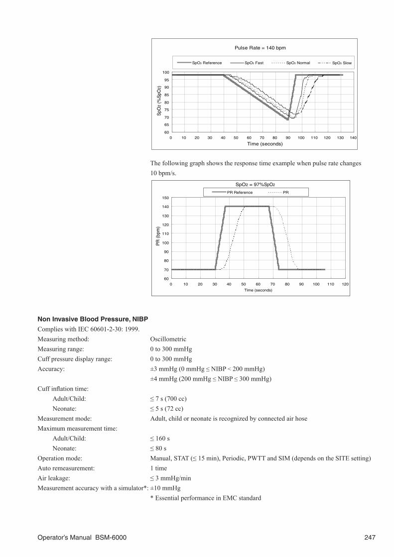
Operator’s Manual BSM-6000 247
60
65
70
75
80
85
90
95
100
0 10 20 30 40 50 60 70 80 90 100 110 120 130 140
SpO2 Reference SpO2 Fast SpO2 Normal
Pulse Rate = 140 bpm
Time (seconds)
SpO
2 (%
SpO
2)
SpO2 Slow
The following graph shows the response time example when pulse rate changes 10 bpm/s.
SpO2 = 97%SpO2
60
70
80
90
100
110
120
130
140
150
0 10 20 30 40 50 60 70 80 90 100 110 120
Time (seconds)
PR
(bpm
)
PR Reference PR
Non Invasive Blood Pressure, NIBP
Complies with IEC 60601-2-30: 1999.Measuring method: OscillometricMeasuring range: 0 to 300 mmHgCuff pressure display range: 0 to 300 mmHgAccuracy: ±3 mmHg (0 mmHg ≤ NIBP < 200 mmHg) ±4 mmHg (200 mmHg ≤ NIBP ≤ 300 mmHg)Cuff inflation time: Adult/Child: ≤ 7 s (700 cc) Neonate: ≤ 5 s (72 cc)Measurement mode: Adult, child or neonate is recognized by connected air hoseMaximum measurement time: Adult/Child: ≤ 160 s Neonate: ≤ 80 sOperation mode: Manual, STAT (≤ 15 min), Periodic, PWTT and SIM (depends on the SITE setting)Auto remeasurement: 1 timeAir leakage: ≤ 3 mmHg/minMeasurement accuracy with a simulator*: ±10 mmHg * Essential performance in EMC standard

248 Operator’s Manual BSM-6000
Initial pressurization value: Adult: 180 mmHg Child: 140 mmHg Neonate: 100 mmHgMaximum pressurization value: Adult/Child: 300 mmHg Neonate: 150 mmHgDisplay items: Systolic (SYS), diastolic (DIA), mean (MAP), cuff pressure during NIBP
measurement, delta PWTTNIBP data display update cycle: Updated every measurementMeasurement completion sound: Generated at measurement completion (depends on the setting)Alarm Upper limit range: 15 to 260 mmHg in 5 mmHg steps, OFF Lower limit range: OFF, 10 to 255 mmHg in 5 mmHg stepsSafety Maximum pressurization value cuff inflation limiter: Adult/Child: 300 to 330 mmHg Neonate: 150 to 165 mmHg Cuff inflation time limiter: Adult/Child: 161 to 165 s Neonate: 81 to 84 s Interval time limiter: 25 to 29 s Power discontinuity: Deflate immediately after power down
Multi Socket
Input impedance: ≥ 900 kWExcitor output impedance: ≤ 2 WExcitor overcurrent protection: 100 mA+5 V maximum power output from the socket: 500 mA
Invasive Blood Pressure, IBP
Complies with IEC 60601-2-34: 2000 except for clauses 44.6, 45.101 a) and 45.101 b).Complied transducer: P23XL-1 and P10EZ-1 Argon Medical Devices reusable transducers Argon Medical Devices disposable transducers DX series 5 μV/V/mmHg, bridge resistor: 200 W to 20 kW, defibrillation-proof or the
equivalentsVolume displacement: 0.04 mm3/100 mmHgAuto zero balancing range: ±200 mmHgAuto zero balancing accuracy: ±1 mmHgMeasuring range: –50 to 300 mmHgMeasuring accuracy: ±1 mmHg ±1 digit (–50 mmHg ≤ IBP < 100 mmHg) ±1% ±1 digit (100 mmHg ≤ IBP ≤ 300 mmHg)Total measuring accuracy*: ±4% or ±4 mmHg (whichever is greater)** * Essential performance in EMC standard ** When used with ANSI/AAMI BP-22-1994 complied equipmentsInternal noise: within ±1 mmHgTemperature zero drift: ±0.1 mmHg/1°CFrequency response: DC to 12 Hz or 20 Hz (selectable)Display items: Systolic (SYS), diastolic (DIA), mean (MEAN)Display update cycle: Every 3 s or when alarm is generatedBP sync sound: Systolic value 20 to 120 mmHg, changes in 20 steps every 5 mmHg

Operator’s Manual BSM-6000 249
Alarm: Upper limit range: –48 to 300 mmHg in 2 mmHg steps, OFF Lower limit range: OFF, –50 to 298 mmHg steps in 2 mmHg steps Alarm inactivation: Alarm is inactivated in certain period when zero balancing is performed.Pulse rate Counting range: 0, 30 to 300 beats/min Display range: 0 to 300 beats/min Counting accuracy (rms): ±2 beats/min (30 beats/min ≤ PR ≤ 300 beats/min) Alarm: Upper limit range: When SYNC SOURCE is set to ECG: 16 to 300 beats/min in 1 beat/min steps, OFF When SYNC SOURCE is set to PRESS or SpO2: 31 to 300 beats/min in 1 beat/min steps, OFF Lower limit range: When SYNC SOURCE is set to ECG: OFF, 15 to 299 beats/min in 1 beat/min steps When SYNC SOURCE is set to PRESS or SpO2: OFF, 30 to 299 beats/min in 1 beat/min steps
Temperature
Complies with EN 12470-4: 2000 only for clauses 6.2, 6.3 a), 6.5, 6.6, 6.7, 6.8, 6.9, 6.10 and 8.Thermistor probe: 400 series (YSI)Number of channels: Up to 4 (2 channels fixed TEMP sockets and 1 MULTI socket)Measuring range: 0 to 45°C, 32 to 113°FMeasuring accuracy*: ±0.1°C (25°C ≤ TEMP ≤ 45°C) ±0.2°C ( 0°C ≤ TEMP < 25°C) * Essential performance in EMC standardInternal noise: ≤ 0.014°C (at 37°C)Temperature drift: within ±0.005°C /°CDisplay range: 0 to 45°C (32 to 113°F)Display update cycle: Every 3 s or when alarm is generatedTime response delay from probe to monitor display: ≤ 6 seconds (sensor time constant is not included)Alarm Upper limit range: 0.1 to 45.0°C (33 to 113°F) in 0.1°C (1°F) steps, OFF Lower limit range: OFF, 0.0 to 44.9°C (32 to 112°F) in 0.1°C (1°F) steps
Carbon Dioxide, CO2 (Mainstream method)For the TG-900P/TG-920P/TG-950P*/TG-970P/TG-980P CO2 sensor kit specifications, refer to the kit manual.* TG-950P is not available for BSM-6000A series.Calculation method TG-900P/TG-920P: semi-quantitative TG-950P/TG-970P/TG-980P: quantitativeCO2 measuring range TG-900P/TG-920P/TG-950P: 0 to 100 mmHg TG-970P/TG-980P: 0 to 150 mmHgCO2 measuring accuracy** TG-900P/TG-920P: ±0.4 kPa (0 ≤ CO2 ≤ 1.33 kPa) (±3 mmHg (0 ≤ CO2 ≤ 10 mmHg)) ±0.53 kPa (1.33 < CO2 ≤ 5.33 kPa) (±4 mmHg (10 < CO2 ≤ 40 mmHg)) ±10% reading (5.33 < CO2 ≤ 13.3 kPa (40 < CO2 ≤ 100 mmHg)) (At 1 atmospheric pressure, air inspiration, no condensation)

250 Operator’s Manual BSM-6000
TG-950P/TG-970P/TG-980P: ±0.27 kPa (0 ≤ CO2 ≤ 5.33 kPa) (±2 mmHg (0 ≤ CO2 ≤ 40 mmHg)) ±5% reading (5.33 < CO2 ≤ 9.33 kPa (40 < CO2 ≤ 70 mmHg)) ±7% reading (9.33 < CO2 ≤ 13.3 kPa (70 < CO2 ≤ 100 mmHg)) (When no condensation) ** Essential performance in EMC standardWarm-up time: TG-900P/TG-920P: 5 s TG-950P: 15 s TG-970P/TG-980P: 10 sResponse time TG-900P: 160 ms (typical) for steps from 10 to 90% TG-920P/TG-950P/TG-970P: 120 ms (typical) for steps from 10 to 90% TG-980P: < 60 ms (typical) for steps from 10 to 90%Respiration rate counting range TG-900P/TG-920P: 3 to 150 counts/min TG-950P/TG-970P/TG-980P: 0 to 150 counts/minRespiration rate counting accuracy TG-900P/TG-920P: ±10% (3 to 150 counts/min) TG-950P/TG-970P/TG-980P: ±1 count/minCO2 value display update cycle: Every 3 s or when alarm is generatedCO2 alarm: Upper limit: CO2 (I): 1 to 99 mmHg in 1 mmHg steps, OFF 0.1 to 13.0 kPa in 0.1 kPa steps, OFF ETCO2: 2 to 99 mmHg in 1 mmHg steps, OFF 0.2 to 13.0 kPa in 0.1 kPa steps, OFF Lower limit: ETCO2: OFF, 1 to 98 mmHg in 1 mmHg steps OFF, 0.1 to 12.9 kPa in 0.1 kPa stepsRespiration rate alarm: Upper limit range: 2 to 150 counts/min in 2 counts/min steps, OFF Lower limit range: OFF, 0 to 148 counts/min in 2 counts/min stepsApnea time: OFF, 5 to 40 s in 5 s steps Displayed message: APNEATotal system response time: ≤ 1.0 second
Inspired Oxygen Fractional Concentration, O2
Measuring parameters: Inspired oxygen fraction concentrationNumber of channels: 1Calibration condition: 21 or 100% O2
Measuring range: 10 to 100% O2
Accuracy*: ±3% full scale (includes sensor, when calibrated with air) * Essential performance in EMC standardInternal noise: ≤ 0.12% O2RMS ±0.72% O2
Temperature drift: ±0.12% O2/°CO2 display update cycle: Every 3 s or when alarm is generatedAlarm: Upper limit range: 19 to 100% in 1% steps, OFF Lower limit range: 18 to 99% in 1% steps
Cardiac Output, CO
Measuring method: Thermodilution method

Operator’s Manual BSM-6000 251
Measuring parameters: Cardiac output (CO), injectate temperature (Ti), blood temperature (Tb), delta TbNumber of channel: 1Measuring range: Injectate temperature (Ti): 0°C to 27°C (32 to 81°F) Blood temperature (Tb): 15°C to 45°C (59 to 113°F) Thermodilution curve (delta Tb): 0°C to 2.5°C (32 to 37°F) Cardiac output (CO): 0.5 to 20 L/minMeasuring accuracy: Ti: ±0.2°C (0°C to 27°C) Tb: ±0.1°C (25°C ≤ TEMP ≤ 45°C) ±0.2°C (15°C ≤ TEMP < 25°C) CO: ±5%Internal noise: Ti: ≤ 0.025°C RMS Tb: ≤ 0.016°C RMS (correspond to 37°C) Delta Tb: ≤ 0.005°C RMS Temperature drift: Ti: ±0.005°C /°C Tb: ±0.005°C /°CFrequency response (delta Tb): DC to 12 Hz (–3 dB)Injectate volume range: 3, 5, 10 mLDisplay update cycle: Updated every measurementTb alarm Upper limit range: 15.1 to 45.0°C (60 to 113°F) in 0.1°C (1°F) steps, OFF Lower limit range: OFF, 15.0 to 44.9°C (59 to 112°F) in 0.1°C (1°F) steps
Respiration (Thermistor method)
Complied sensor: TR-900P respiration pickup for nose and TR-910P respiration pickup for airwayMeasuring items: Thermistor respiration curve, respiration rateNumber of channel: 1APNEA detection: AvailableRespiration rate counting range: 0 to 150 counts/minRespiration rate counting accuracy*: ±2 counts/min * Essential performance in EMC standardMeasurable temperature range: 10 to 40°CInternal noise: ≤ 2.5 W (Referred to input)Frequency response: 0.1 to 3 Hz (–3 dB)Waveform display: Display sensitivity: 10 mm/100 W ±20% (at ×1 sensitivity) Sensitivity control: ×1/4, ×1/2, ×1, ×2, ×4Respiration rate display update cycle: Every 3 s or when alarm is generatedAlarm: Upper limit range: 2 to 150 counts/min in 2 counts/min steps, OFF Lower limit range: OFF, 0 to 148 counts/min in 2 counts/min steps Apnea alarm: OFF, 5 to 40 s in 5 s steps Displayed message: APNEA
Bispectral Index, BISFor the BISx/BIS processor specifications, refer to the BISx/BIS processor manual.BIS can be monitored with Covidien’s BIS monitor.

252 Operator’s Manual BSM-6000
BIS alarm: Upper limit range: 2 to 100 in 1 steps, OFF Lower limit range: OFF, 0 to 99 in 1 steps
ECG/BP Output
Outputs 100 mmHg/V IBP waveform and the first trace of 1 mV/V ECG waveform. When more than one IBP waveforms are acquired, the IBP waveform of the top MULTI socket is output (when “FIXED POSITION” is set for IBP Analog Output) or the IBP waveform is output following the highest priority label (when “HIGHEST PRIORITY LABEL” is set for IBP Analog Output).Complied medical electrical equipments Connecting medical electrical equipment must comply to the following standards: IEC 60601-1: 1988 IEC 60601-1 Amendment 1: 1991 IEC 60601-1 Amendment 2: 1995 CSA C22.2 No.601.1 Medical electrical equipment must be connected by specified method in following standards: IEC 60601-1-1: 2000 CSA C22.2 No.60601-1-1-02Output impedance: ECG: ≤ 100 W BP: ≤ 100 WOutput-waveform: ECG: ±5.0 V (at 1 mV/V ± 5% sensitivity) BP: –0.5 to +3.0 V (at 100 mmHg/V ± 1% sensitivity) HT: 5.0 to 15.0 V (Open collector output: 0.5 to 50 mA)Frequency response: ECG: ≥ 0.5 to 100 Hz (≥ –3 dB) (No reproducibility of pace maker pulse) BP: ≥ DC to 20 Hz ±3 Hz (–3 dB)HT pulse width: 15 msGain: ECG: 1000Offset: ECG: ≤ ±50 mV BP: ≤ ±10 mVSensitivity accuracy: ECG: ±5% BP: ±1%Delay: ECG, HT: 20 ms max BP: 40 ms max ART (CCO): 60 ms max
RGB Socket (when QI-631P or QI-671P is connected)
Output signal: Analog RGB signal, 0.7 Vp-pResolution: BSM-6301/BSM-6501: 800 × 600 dots BSM-6701: 1024 × 768 dots

Operator’s Manual BSM-6000 253
RS-232C Socket (when QI-631P or QI-671P is connected)
Serial communication: RS-232C compliesBaud rate: 9600, 19200, 38400 bps
Alarm Socket (when QI-632P or QI-671P is connected)
Nurse call output: Open collector output (Low active)
When WS-671P Recorder Module is Connected
Recording method: Thermal array recordingNumber of channels: 3 traces (maximum)Recording width: ≥ 46 mmPaper speed: 12.5, 25, 50 mm/s Recording mode: Manual, periodic, alarmRecording density: Amplitude direction: 8 dots/mm Feeding direction: 40 dots/mm (≤ 25 mm/s) 20 dots/mm (50 mm/s)Recording paper: FQW-50-2-100
When ZS-900P Transmitter is Connected
ZS-900P transmitter is not available for BSM-6000A series.Frequency capacity deviation: ≤ ±3 ppm (15 to 35°C)Transmission power: 1.0 mW +5%, –40% (15 to 35°C)Spurious emission strength: ≤ 2.5 μW (5 MHz to 1.5 GHz)Occupied bandwidth: 5.0 to 8.5 kHzAdjacent channel leaking power: ≥ 40 dBRTransmission frequency range: 420.0500 to 449.6625 MHzModulation method: Frequency shift keying
Gas
Gas can be monitored with the AG-920R, GF-110PA or GF-210R multigas unit or GF-120PA or GF-220R multigas/flow unit. For the AG-920R, GF-110PA or GF-210R multigas unit or GF-120PA or GF-220R multigas/flow unit specifications, refer to the manual.Measurement method: Sidestream gas samplingMeasured parameters: Inspired/expired CO2 partial pressure, inspired/expired N2O concentration,
inspired expired O2 concentration, inspired/expired anesthetic agent concentration (Halothane, Isoflurane, Enflurane, Sevoflurane, Desflurane), respiration rate, minimum alveolar concentration
Warm-up time: AG-920R, GF-110PA/120PA: within 45 seconds to first measurement within 10 minutes to measurement with guaranteed accuracy GF-210R/220R: about 1 minute to CO2 measurement about 6 minutes to measurement with guaranteed accuracySampling rate: 70 to 100 mL/min ±10 mL/min 100 to 200 mL/min ±10%relTotal system response time: AG-920R, GF-110PA/120PA: ≤ 5.0 seconds (when sampling volume is 200 mL/min, using adult sampling tube
and adult water trap) GF-210R/220R: ≤ 5.0 seconds (when YG-610P sampling line is connected)

254 Operator’s Manual BSM-6000
CO2 measurement: Measurement method: Non-dispersive infrared ray absorption Measuring range: AG-920R, GF-110PA/120PA: 0 to 76 mmHg, 0 to 10.13 kPa GF-210R/220R: 0 to 10 vol% Measuring accuracy: AG-920R, GF-110PA/120PA: ±2 mmHg (0 ≤ CO2 ≤ 40 mmHg), ±0.27 kPa
(0 ≤ CO2 ≤ 5.33 kPa) ±3 mmHg (40 ≤ CO2 ≤ 55 mmHg), ±0.40 kPa
(5.33 ≤ CO2 ≤ 7.33 kPa) ±4 mmHg (55 < CO2 ≤ 76 mmHg), ±0.53 kPa
(7.33 < CO2 ≤ 10.13 kPa)NOTE for AG-920R and GF-110PA/120PA:
CO2 measurement accuracy is maintained up to a respiratory rate of 60 bpm with I:E ratio of 1:3, 1:2, 1:1 and 2:1.
GF-210R/220R: ± (0.43 vol% + 8%rel)NOTE for GF-210R and GF-220R:
CO2 measurement accuracy is maintained up to a respiratory rate of 60 bpm with I:E ratio of 1:2.
Response time (10 to 90%): AG-920R, GF-110PA/120PA: ≤ 250 ms (under the condition of sampling flow is 200 mL/min and sampling
line for adult and water trap for adult is connected)
Alarm: Upper limit: CO2(I): 1 to 99 mmHg in 1 mmHg steps, OFF 0.1 to 13.0 kPa in 0.1 kPa steps, OFF ETCO2: 2 to 99 mmHg in 1 mmHg steps, OFF 0.2 to 13.0 kPa in 0.1 kPa steps, Off Lower limit: ETCO2: OFF, 1 to 98 mmHg in 1 mmHg steps OFF, 0.1 to 12.9 kPa in 0.1 kPa stepsN2O measurement: Measurement method: Non-dispersive infrared ray absorption Measuring range: AG-920R, GF-110PA/120PA: 0 to 100% GF-210R/220R: 0 to 100 vol% Measuring accuracy: AG-920R, GF-110PA/120PA: ±3%NOTE for AG-920R and GF-110PA/120PA:
N2O measurement accuracy is maintained up to a respiratory rate of 30 bpm with I:E ratio of 1:3, up to a respiratory
rate of 40 bpm with I:E ratio of 1:2 and up to a respiratory rate of 60 bpm with I:E ratio of 1:1 and 2:1.
GF-210R/220R: ±(2vol% + 8%rel)NOTE: N2O measurement accuracy is maintained up to a respiratory rate of 60 bpm with I:E ratio of 1:2.
Response time (10 to 90%): AG-920R, GF-110PA/120PA: ≤ 250 ms (under the condition of sampling flow is 200 mL/min and sampling line for adult and water trap for adult is connected)
Alarm (N2O(I), N2O(E)): Upper limit: 1 to 100% in 1% steps, OFF Lower limit: OFF, 0 to 99% in 1% stepsO2 measurement: Measurement method: Paramagnetic Measuring range: 0 to 100% Measuring accuracy: AG-920R, GF-110PA/120PA: ±2% (0 ≤ O2 ≤ 55%) ±3% (55 < O2 ≤ 100%) GF-210R/220R: ±(2.5 vol% + 2.5%rel)

Operator’s Manual BSM-6000 255
NOTE for GF-210R/220R:
O2 measurement accuracy is maintained up to a respiratory rate of 60 bpm with I:E ratio of 1:2.
Response time (10 to 90%): AG-920R, GF-110PA/120PA: ≤ 500 ms (under the condition of sampling flow is 200 mL/min and sampling line for adult and water trap for adult is connected)
Alarm: Upper limit: O2(I): 19 to 100% in 1% steps, OFF O2(E): 11 to 100% in 1% steps, OFF Lower limit: O2(I): 18 to 99% in 1% steps O2(E): OFF, 10 to 99% in 1% stepsAnesthetic agent measurement: Measurement method: Non-dispersive infrared ray absorption Measured items: HAL (Halothane), ISO (Isoflurane), ENF (Enflurane), SEV (Sevoflurane), DES
(Desflurane) Measuring range: AG-920R, GF-110PA/120PA: HAL, ISO, ENF 0 to 5% SEV 0 to 8% DES 0 to 18% GF-210R/220R: HAL, ISO 0 to 8.5 vol% ENF, SEV 0 to 10 vol% DES 0 to 20% vol% Measuring accuracy: AG-920R, GF-110PA/120PA: ±0.2% (0 ≤ GAS ≤ 5%) ±0.4% (5 < GAS ≤ 10%) ±0.6% (10 < GAS ≤ 15%) ±1.0% (15 < GAS ≤ 18%)NOTE for AG-920R, GF-110PA and GF-120PA:
Anesthetic agent accuracy is maintained up to a respiratory rate of 60 bpm with I:E ratio of 1:3, 1:2, 1:1 and 2:1.
GF-210R/220R: ± (0.2 vol% +15%rel)NOTE for GF-210R/220R:
Anesthetic agent accuracy is maintained up to a respiratory rate of 60 bpm with I:E ratio of 1:2.
Response time (10 to 90%): AG-920R, GF-110PA/120PA: ≤ 300 ms (HAL, ISO, SEV, DES) ≤ 500 ms (ENF) (under the condition of sampling flow is 200
mL/min and sampling line for adult and water trap for adult is connected)
Alarm: Upper limit: Agent(I), Agent(E) (HAL, ISO, SEV, ENF): 0.1 to 7.0% in 0.1% steps, OFF
DES(I), DES(E): 0.1 to 20.0% in 0.1% steps, OFF Lower limit: Agent(I), Agent(E) (HAL, ISO, SEV, ENF): OFF, 0.0 to 6.9% in 0.1% steps, OFF DES(I), DES(E): OFF, 0.0 to 19.9% in 0.1% stepsMAC:Uncorrected MAC: When AG-920R multigas unit is connected Uncorrected MAC = %Et(AA1)/x(AA1) + %Et(AA2)/x(AA2) + %Et(N2O)/x(N2O) %Et(AA1): End tidal concentration of primary anesthetic agent %Et(AA2): End tidal concentration of secondary anesthetic agent %Et(N2O): End tidal concentration of N2O

256 Operator’s Manual BSM-6000
x(AA1): Uses the following values with the MAC of primary anesthetic agent HAL = 0.77%, ENF = 1.7%, ISO = 1.15%, SEV = 2.1%, DES = 6.0%* x(AA2): Uses the following values with the MAC of secondary anesthetic agent HAL = 0.77%, ENF = 1.7%, ISO = 1.15%, SEV = 2.1%, DES = 6.0%* x(N2O): Uses 105% with the MAC of N2O
* NOTE: DES value is 7.3% if the BSM-6000 series bedside monitor has software version 04-14 or earlier. When
using two or more AG-920R multigas units in a facility, use bedside monitors with the same software version.
For the GF-110PA or GF-210R multigas unit and GF-120PA or GF-220R multigas/flow unit, refer to the manual.
Ambient pressure corrected MAC: For GF-110PA or GF-210R multigas unit and GF-120PA or GF-220R multigas/flow unit, refer to the manual.
Enhanced MAC correction: For GF-110PA or GF-210R multigas unit and GF-120PA or GF-220R multigas/flow unit, refer to the manual.
Respiration rate: Measuring range: 0, 4 to 60 counts/min Measuring accuracy: ±1 count/min Alarm: Upper limit: 2 to 150 counts/min in 2 counts/min steps, OFF Lower limit: OFF, 0 to 148 counts/min in 2 counts/min steps Apnea alarm: OFF, 5 to 40 s in 5 s steps Displayed message: APNEA
Carbon Dioxide, CO2 (Sidestream method)
CO2 in sidestream method can be monitored with the AG-400R CO2 unit.For the AG-400R CO2 unit specifications, refer to the AG-400R CO2 unit manual.Sampling flow: 50 mL/min +15/−7.5 mL/minWarm up time: 30 s average (from power on to the measurable state)Measuring range: 0 to 99 mmHgTotal measuring accuracy: Whichever greater in following measuring accuracyMeasuring accuracy: 0 to 38 mmHg ±2 mmHg 39 to 99 mmHg ± [5 + 0.08 × (χ − 39)] % of reading
χ: CO2 partial pressure of a standard gas with a known CO2 partial pressure (mmHg)ETCO2 and CO2(I) alarm: Upper limit: CO2(I) : 1 to 99 mmHg in 1 mmHg steps, OFF 0.1 to 13.0 kPa in 0.1 kPs steps, OFF ETCO2: 2 to 99 mmHg in 1 mmHg steps, OFF 0.2 to 13.0 kPa in 0.1 kPa steps, OFF Lower limit: ETCO2: OFF, 1 to 98 mmHg in 1 mmHg steps OFF, 0.1 to 12.9 kPa in 0.1 kPa stepsRespiration rate measuring range: 0 to 150 counts/minRespiration rate measuring accuracy: 101 to 150 counts/min: ±5% 71 to 100 counts/min: ±3% 41 to 70 counts/min: ±2 counts/min 0 to 40 counts/min: ±1 count/minRespiration rate alarm: Upper limit range: 2 to 150 counts/min in 2 counts/min steps, OFF Lower limit range: OFF, 0 to 148 counts/min in 2 counts/min steps Apnea alarm: OFF, 5 to 40 s in 5 s steps Displayed message: APNEA

Operator’s Manual BSM-6000 257
Total system response time: ≤ 4 seconds
FLOW/Paw
Flow/Paw can be monitored with the GF-120PA or GF-220R multigas/flow unit. For the GF-120PA or GF-220R multigas/flow unit specifications, refer to the GF-120PA or GF-220R multigas/flow unit manual.
FLOW measurement:Measurement method: Differential pressure method (fixed orifice) Measuring range: –3 to +3 L/s Measuring accuracy: ±3% rel or ±0.005 L/s whichever is greater Applicable when 10 minutes or more has elapsedPaw measurement: Ppeak, Pmean, PEEP: Measuring range: –20 to +100 cmH2O, hPa Measuring accuracy: ±1 cmH2O, hPa Applicable when 10 minutes or more has elapsed Ppeak alarm: Upper limit range: 1 to 100 cmH2O, hPa in 1 cmH2O, hPa steps, OFF Lower limit range: OFF, 0 to 99 cmH2O, hPa in 1 cmH2O, hPa steps PEEP alarm: Upper limit range: 1 to 50 cmH2O, hPa in 1 cmH2O, hPa steps, OFF Lower limit range: OFF, 0 to 49 cmH2O, hPa in 1 cmH2O, hPa stepsVolume measurement: Measuring range: 0 to 3000 mL Measuring accuracy: ±5% rel or ±10 mL whichever is greater Applicable when 10 minutes or more has elapsedTVe, TVi measurement: Measuring range: 0 to 3000 mL Display range: 0 to 9999 mL Measuring accuracy: ±5% rel or ±10 mL whichever is greater Applicable when 10 minutes or more has elapsed Not applicable when TVi and TVe is less than 100 mLMV measurement: Display range: 0 to 99.9 L/min Alarm: Upper limit range: 0.1 to 30.0 L/min in 0.1 L/min steps, OFF Lower limit range: OFF, 0.0 to 29.9 L/min in 0.1 L/min stepsC measurement: Display range: 0.0 to 999.9 mL/cmH2OR, Ri, Re measurement: Display range: 0.0 to 999.9 cmH2O/L/sRespiration rate measurement: Counting range: 0, 4 to 60 counts/min Counting accuracy: ±1 counts/min Alarm: Upper limit range: 2 to 150 counts/min in 2 counts/min steps, OFF Lower limit range: OFF, 0 to 148 counts/min in 2 counts/min steps Apnea time: OFF, 5 to 40 s in 5 s steps Displayed message: APNEA
EEG
EEG can be monitored with the AE-918P neuro unit. For the AE-918P neuro unit specifications, refer to the AE-918P neuro unit manual.
Number of channels: 8

258 Operator’s Manual BSM-6000
Measuring range: SEF, MDF, PPF: 0.0 to 62.5 Hz TP: 0.01 to 9.99 nW ABS δ, ABS θ, ABS α, ABS β, ABS γ: 1 to 9999 pW % δ, % θ, % α, % β, % γ: 0 to 100% CSA: 0 to 60 Hz DSA: 0 to 60 Hz aEEG trace: 0.0 to 100.0 μV aEEG value: 0.0 to 3276.7 μVData display update cycle: Every 3 s or when alarm is generatedElectrode impedance check: > 10 kW within ±20%Sensitivity: 10 µV/1 mm within ±5%Non distorted maximum input: > ±2 mVPolarization voltage: > ±700 mVInput impedance: > 15 MW at 10 HzCMRR: > 110 dB (in isolation mode)Frequency characteristics: High range: 70 Hz at 70% amplitude (−3 dB) within ±20% Low range: 2 s ±20% or 0.08 Hz at 70% amplitude (−3 dB) within ±20%AC filter: attenuation ratio > 26 dBNoise: within 3 µVp-pSEF alarm: Upper limit range: 1.0 to 60.0 Hz in 0.5 Hz steps, OFF Lower limit range: OFF, 0.5 to 59.5 Hz in 0.5 Hz stepsTP alarm: Upper limit range: 0.02 to 9.99 nW in 0.01 nW steps, OFF Lower limit range: OFF, 0.01 to 9.98 nW in 0.01 nW steps
CCOFor the APCO/IBP processor specifications, refer to the APCO/IBP processor manual.
CCO alarm: Upper limit range: 1.1 to 20.0 L/min in 0.1 L/min steps, OFF Lower limit range: OFF, 1.0 to 19.9 L/min in 0.1 L/min stepsCCI alarm: Upper limit range: 1.1 to 20.0 L/min/m2 in 0.1 L/min/m2 steps, OFF Lower limit range: OFF, 1.0 to 19.9 L/min/m2 in 0.1 L/min/m2 steps
Battery (SB-671P Battery Pack)
Type of battery: Nickel-metal hydrideNumber of batteries: 2Battery lifetime: 1 year or 200 cycles of full discharging/chargingBattery operation time: BSM-6301/6501: 90 minutes BSM-6701: 60 minutes (new battery, fully charged and no options are used in normal temperature)DC voltage: 9.6 VCharging current: 360 mA ±50 mA (normal use)

Operator’s Manual BSM-6000 259
Charging time: During monitoring: 10 hours During non-monitoring: 6 hours (two battery at the same time)Battery status indication: Battery lamps on the front panel, screen message and alarm sound, alarm indicatorOperating environment: Charging temperature: 10 to 55°C (50 to 131°F) Discharging temperature: 5 to 50°C (41 to 122°F) Humidity: 30 to 85% RH (noncondensing) Atmospheric pressure: 700 to 1060 hPaTransport and storage environment: When the battery pack is stored more than 6 months, charge and discharge or charge
the battery once every 6 months. Temperature: –20 to +60°C (–4 to +140°F) (within 30 days) –20 to +45°C (–4 to +113°F) (within 90 days) –20 to +35°C (–4 to +95°F) (more than 90 days) Humidity: 20 to 85% RH (noncondensing) Atmospheric pressure: 700 to 1060 hPa
Power Requirement
Line voltage: AC: AC 100 to 240 V ±10% DC (SB-671P): 8.5 to 12.6 VLine frequency: 50 or 60 HzPower input: BSM-6301: AC 140 VA BSM-6501: AC 90 VA BSM-6701: AC 100 VA
Clock Accuracy
At operating temperature 25°C: approx. ±2 min 40 s/month maximumAt storage temperature –20 to +60°C: approx. ±6 min/month maximum
Environment
Operating environment: Temperature: 10 to 40°C (50 to 104°F) SpO2 accuracy is guaranteed at surrounding temperature of 18 to 40°C (60 to 104°F) Humidity: 30 to 85% RH (10 to 40°C, noncondensing) Atmospheric pressure: 700 to 1060 hPaTransport and storage environment: Temperature: –20 to +65°C (–4 to +149°F) –15 to +55°C (Recording paper) Humidity: 10 to 95% RH Atmospheric pressure: 700 to 1060 hPa
Mechanical Strength
Mechanical strength: Indoor mobile type
Electromagnetic Compatibility
IEC 60601-1-2: 2001 IEC 60601-1-2 Amendment 1: 2004

260 Operator’s Manual BSM-6000
Safety Standard
Safety standard: CAN/CSA C22.2 No. 601-1 M90 (BSM-6501A, BSM-6701A) CAN/CSA C22.2 No. 601-1S1-94 (BSM-6501A, BSM-6701A) CAN/CSA C22.2 No. 601-1B-98 (BSM-6501A, BSM-6701A) CAN/CSA C22.2 No. 60601-1-1-02 (BSM-6501A, BSM-6701A) CAN/CSA C22.2 No. 601.2.27-98 (BSM-6501A, BSM-6701A) CAN/CSA C22.2 No. 60601-2-30-02 (BSM-6501A, BSM-6701A) CAN/CSA C22.2 No. 60601-2-34-02 (BSM-6501A, BSM-6701A) CAN/CSA C22.2 No. 60601-2-49-04 (BSM-6501A, BSM-6701A) EN 12470-4: 2000*1
IEC 60601-1: 1988 IEC 60601-1 Amendment 1: 1991 IEC 60601-1 Amendment 2: 1995 IEC 60601-1-1: 2000 IEC 60601-1-2: 2001 IEC 60601-1-2 Amendment 1: 2004 IEC 60601-1-6: 2010 IEC 60601-1-8: 2006*2*3
IEC 60601-2-27: 2005 - Particular requirements for the safety, including essential performance, of electrocardiographic monitoring equipment
IEC 60601-2-30: 1999 - Particular requirements for the safety of automatic cycling in in-direct blood pressure monitoring equipment
IEC 60601-2-34: 2000 - Particular requirements for the safety of direct blood pressure monitoring equipment*4
IEC 60601-2-49: 2001 - Particular requirements for the safety of multifunction patient monitoring equipment
ISO 21647: 2004 ISO 9919: 2005
*1 This monitor complies with EN 12470-4: 2000 only for clauses 6.2, 6.3 a), 6.5, 6.6, 6.7, 6.8, 6.9, 6.10 and 8.
*2 Only the “IEC standard” alarm sound complies with clause 6.3.3.2.*3 This monitor complies with IEC 60601-1-8: 2006 except for interbed alarm.*4 This monitor complies with IEC 60601-2-34: 2000 except for clauses 44.6,
45.101 a) and 45.101 b).Type of protection against electrical shock: CLASS I EQUIPMENT (AC Powered) Internally Powered EQUIPMENT (BATTERY Powered)Degree of protection against electrical shock Defibrillator-proof type CF applied part: AY-631P, AY-633P, AY-651P, AY-653P, AY-661P, AY-663P, AY-671P and AY-673P: ECG, Respiration (impedance and thermistor method), IBP, Temperature, SpO2,
SpO2-2, CO2, O2, NIBP, BIS, CCO (APCO) AY-660P: ECG, Respiration (impedance method), IBP, Temperature, SpO2, CO2, NIBP AA-672P, AA-674P, JA-694P: Respiration (thermistor method), IBP, Temperature, SpO2-2, CO2, O2, BIS, CCO
(APCO) BSM-1700 series: ECG, Respiration (impedance method), IBP, Temperature, SpO2, SpO2-2, CO2,
NIBP, BIS CF applied part: AY-631P, AY-633P, AY-651P, AY-653P, AY-661P, AY-663P, AY-671P, AY-673P, AA-672P, AA-674P, JA-694P and
BSM-1700 series: CO
Operator’s Manual BSM-6000 261
Degree of protection against harmful ingress of water: IPX0 (non-protected)Degree of safety of application in the presence of FLAMMABLE ANAESTHETIC MIXTURE WITH AIR, OR WITH OXYGEN OR NITROUS OXIDE: Equipment not suitable for use in the presence of FLAMMABLE
ANAESTHETIC MIXTURE WITH AIR, OR WITH OXYGEN OR NITROUS OXIDE
Mode of operation: CONTINUOUS OPERATION
Dimensions and Weight (approximate)
MU-631R main unit: Dimensions: 316 W × 325 H × 188 D mm (excluding protruding parts) Weight: 5.3 kgMU-651R main unit: Dimensions: 342 W × 353 H × 183 D mm (excluding protruding parts) Weight: 7.0 kgMU-671R main unit: Dimensions: 415 W × 392 H × 191 D mm (excluding protruding parts) Weight: 9.0 kgAY-631P/AY-633P/AY-651P/AY-653P/AY-660P/AY-661P/AY-663P/AY-671P/AY-673P input unit: Dimensions: 83 W × 176 H × 145 D mm (excluding protruding parts) Weight: 1.3 kgAA-672P/AA-674P smart expansion unit: Dimensions: 38 W × 165 H × 145 D mm (excluding protruding parts) Weight: 0.5 kgWS-671P recorder module: Dimensions: 77 W × 73 H × 120 D mm (excluding protruding parts) Weight: 0.35 kgQI-631P interface: Dimensions: 28.5 W × 94 H × 106 D mm (excluding protruding parts) Weight: 0.1 kgQI-632P/QI-634P interface: Dimensions: 27 W × 94 H × 106 D mm (excluding protruding parts) Weight: 0.1 kgQI-671P interface: Dimensions: 29 W × 173 H × 112 D mm (excluding protruding parts) Weight: 0.16 kgQI-672P interface: Dimensions: 26 W × 173 H × 107 D mm (excluding protruding parts) Weight: 0.15 kgRY-910PA remote controller: Dimensions: 45 W × 35 H × 135 D mm Weight: 0.08 kgInterface QF series: Dimensions: 65 W × 23 H × 44 D mm (excluding cables) Weight: 0.13 kgCommunication cable IF series: Dimensions: 65 W × 23 H × 44 D mm (excluding cables) Weight: 0.13 kgJA-690PA/JA-694PA data acquisition unit: Dimensions: 145 mm W × 205 mm H × 190 mm D Weight: 1.8 kg (JA-690PA), 2.0 kg (JA-694PA)BSM-1700 series bedside monitor: Refer to the manuals of the BSM-1700 series bedside monitor.
262 Operator’s Manual BSM-6000
Electromagnetic Emissions
The BSM-6000’s essential performances in EMC standard satisfy the following criteria.
This Model BSM-6000 is intended for use in the electromagnetic environment specified below.The customer or the user of the BSM-6000 should assure that it is used in such an environment.
BSM-6301 and BSM-6501 (JA-690PA or JA-694PA data acquisition unit, QE-910P BIS processor, AE-918P neuro unit, JP-911P IBP interface isolation cable, QI-320PA or QI-420PA wireless LAN station and QI-670P interface are not connected)
Emissions test Compliance Electromagnetic environment - guidanceRF emissionsCISPR 11
Group 1 The BSM-6301 and BSM-6501 (JA-690PA/JA-694PA, QE-910P, AE-918P, JP-911P, QI-320PA/QI-420PA and QI-670P are not connected) use RF energy only for its internal function. Therefore, its RF emissions are very low and are not likely to cause any interference in nearby electronic equipment.
RF emissionsCISPR 11
Class B*1 The BSM-6301 and BSM-6501 (JA-690PA/JA-694PA, QE-910P, AE-918P, JP-911P, QI-320PA/QI-420PA and QI-670P are not connected) are suitable for use in all establishments, including domestic establishments and those directly connected to the public low-voltage power supply network that supplies buildings used for domestic purposes.
Harmonic emissionsIEC 61000-3-2
Class A*2
Voltage fluctuations/flicker emissionsIEC 61000-3-3
Complies
*1 BSM-6301 and BSM-6501 (when ZS-900P is connected) are CLASS A equipment if the equipments comply with IEC 60601-1-2: 2001 36.201.1 5 in the countries which do not have national wireless rule.
*2 BSM-6301 is not applicable.
BSM-6301, BSM-6501 (JA-690PA or JA-694PA data acquisition unit, QE-910P BIS processor, AE-918P neuro unit, JP-911P IBP interface isolation cable, QI-320PA or QI-420PA wireless LAN station or QI-670P interface is connected) and BSM-6701
Emissions test Compliance Electromagnetic environment - guidanceRF emissionsCISPR 11
Group 1 The BSM-6301, BSM-6501 (JA-690PA/JA-694PA, QE-910P, AE-918P, JP-911P, QI-320PA/QI-420PA or QI-670P is connected) and BSM-6701 use RF energy only for its internal function. Therefore, its RF emissions are very low and are not likely to cause any interference in nearby electronic equipment.
RF emissionsCISPR 11
Class A The BSM-6301, BSM-6501 (JA-690PA/JA-694PA, QE-910P, AE-918P, JP-911P, QI-320PA/QI-420PA or QI-670P is connected) and BSM-6701 are suitable for use in all establishments, excluding domestic establishments and those directly connected to the public low-voltage power supply network that supplies buildings used for domestic purposes.
Harmonic emissionsIEC 61000-3-2
Class A*
Voltage fluctuations/flicker emissionsIEC 61000-3-3
Complies
* BSM-6301 is not applicable.

Operator’s Manual BSM-6000 263
Electromagnetic Immunity
The BSM-6000’s essential performances in EMC standard satisfy the following criteria.
This Model BSM-6000 is intended for use in the electromagnetic environment specified below.The customer or the user of the BSM-6000 should assure that it is used in such an environment.
Immunity test IEC 60601 test level Compliance levelElectromagnetic environment -
guidanceElectrostatic discharge (ESD)IEC 61000-4-2
±6 kV contact±8 kV air
±6 kV contact±8 kV air
Floors should be wood, concrete or ceramic tiles. If floors are covered with synthetic material, the relative humidity should be at least 30%.
Electrical fast transient/ burstIEC 61000-4-4
±2 kV for power supply lines±1 kV for input/output lines
±2 kV for power supply lines±1 kV for input/output lines
Mains power quality should be that of a typical commercial or hospital environment.
SurgeIEC 61000-4-5
±1 kV differential mode±2 kV common mode
±1 kV differential mode±2 kV common mode
Mains power quality should be that of a typical commercial or hospital environment.
Voltage dips, short interruptions and voltage variations on power supply input linesIEC 61000-4-11
<5% UT (>95% dip in UT) for 0.5 cycles
40% UT (60% dip in UT) for 5 cycles
70% UT (30% dip in UT) for 25 cycles
<5% UT (>95% dip in UT) for 5 s
<5% UT (>95% dip in UT) for 0.5 cycles
40% UT (60% dip in UT) for 5 cycles
70% UT (30% dip in UT) for 25 cycles
<5% UT (>95% dip in UT) for 5 s
Mains power quality should be that of a typical commercial or hospital environment.If the user of the BSM-6000 requires continued operation during power mains interruptions, it is recommended that the BSM-6000 be powered from an uninterruptible power supply or a battery.
Power frequency(50/60 Hz)magnetic fieldIEC 61000-4-8
3 A/m 3 A/m Power frequency magnetic fields should be at levels characteristic of a typical location in a typical commercial or hospital environment.
NOTE: UT is the AC mains voltage prior to application of the test level.

264 Operator’s Manual BSM-6000
Immunity testIEC 60601 test
levelCompliance level Electromagnetic environment - guidance
Conducted RF IEC 61000-4-6
Radiated RFIEC 61000-4-3
3 Vrms150 kHz to 80 MHz
3 V/m 80 MHz to 2.5 GHz
3 Vrms
3 V/m 80 MHz to 2.5 GHz
Portable and mobile RF communications equipment should be used no closer to any part of the BSM-6000 including cables than the recommended separation distance calculated from the equation applicable to the frequency of the transmitter.
Recommended separation distance
d = 1.2 P
d = 1.2 P 80 MHz to 800 MHzd = 2.3 P 800 MHz to 2.5 GHz
where P is the maximum output power rating of the transmitter in watts (W) according to the transmitter manufacturer and d is the recommended separation distance in meters (m).
Field strengths from fixed RF transmitters, as determined by an electromagnetic site survey*1, should be less than the compliance level in each frequency range*2.
Interference may occur in the vicinity of equipment marked with the following symbol:
NOTE 1: At 80 MHz and 800 MHz, the higher frequency range applies.NOTE 2: These guidelines may not apply in all situations. Electromagnetic propagation is affected by absorption and
reflection from structures, objects and people.*1 Field strengths from fixed transmitters, such as base stations for radio (cellular/cordless) telephones and land mobile
radios, amateur radio, AM and FM radio broadcast and TV broadcast cannot be predicted theoretically with accuracy. To assess the electromagnetic environment due to fixed RF transmitters, an electromagnetic site survey should be considered. If the measured field strength in the location in which the BSM-6000 is used exceeds the applicable RF compliance level above, the BSM-6000 should be observed to verify normal operation. If abnormal performance is observed, additional measures may be necessary, such as re-orienting or relocating the BSM-6000.
*2 Over the frequency range 150 kHz to 80 MHz, field strengths should be less than 3 V/m.

Operator’s Manual BSM-6000 265
Recommended Separation Distances between Portable and Mobile RF Communications Equipment
The BSM-6000 is intended for use in an electromagnetic environment in which radiated RF disturbances are controlled. The customer or the user of the BSM-6000 can help prevent electromagnetic interference by maintaining a minimum distance between portable and mobile RF communications equipment (transmitters) and the BSM-6000 as recommended below, according to the maximum output power of the communications equipment.
Rated maximum output power of transmitter
(W)
Separation distance according to frequency of transmitter (m)
150 kHz to 80 MHzd = 1.2 P
80 MHz to 800 MHzd = 1.2 P
800 MHz to 2.5 GHzd = 2.3 P
0.01 0.12 0.12 0.230.1 0.38 0.38 0.731 1.2 1.2 2.310 3.8 3.8 7.3100 12 12 23
For transmitters rated at a maximum output power not listed above, the recommended separation distance d in meters (m) can be estimated using the equation applicable to the frequency of the transmitter, where P is the maximum output power rating of the transmitter in watts (W) according to the transmitter manufacturer.NOTE 1: At 80 MHz and 800 MHz, the separation distance for the higher frequency range applies.NOTE 2: These guidelines may not apply in all situations. Electromagnetic propagation is affected by absorption and reflection from structures, objects and people.

266 Operator’s Manual BSM-6000
System Composition for EMC Test
The BSM-6000 bedside monitor is tested to comply with IEC 60601-1-2: 2001 and Amendment 1: 2004 with the following composition. If any part which is not specified by Nihon Kohden is used, the EMC specifications might not comply.
Units Cable length Units Cable length
MU-631R/MU-651R/MU-671R main unit — NE-114A EEG disk electrode 0.8 mAY-633P/AY-660P/AY-673P input unit — YJ-910P ECG/BP output cable 5.0 mQM-600P memory unit — JP-600P APCO/IBP processor 2.72 mAA-674P smart expansion unit — MHD8S FloTrac sensor 0.39 mQI-631P/QI-632P/QI-634P/QI-671P/ QI-672P interface — QF-901P interface (including a cable for
Drager ventilator) —QI-670P interface —BJ-900P ECG patient cable 3.8 m QF-902P interface (including a cable for
A-2000 BIS monitor) —JL-900P SpO2 connection cord 2.5 m
JL-500P1 SpO2 adapter 2.5 m QF-903P interface (including a cable for Vigilance CCO monitor) —
TL-201T finger probe 1.6 mQF-904P interface (including a cable for AG-920R multigas unit) —JL-650P SpO2 connection cord 3.0 m
JL-630P SpO2 connection cord 3.0 mLNOP-DCI Masimo adult reusable sensor — QF-905P interface (including a cable for
AG-400R CO2 unit) —YN-921P air hose for neonate 3.5 mYP-821P disposable cuff for neonate 0.2 m YS-080P3 RGB cable 10 mYN-901P air hose for adult/child 3.5 m YS-089P2 serial connection cable 10 mYP-963T cuff for adult 0.15 m Basic optical mouse —JP-900P IBP connection cord 3.5 m SB-671P battery pack —JP-911P IBP connection cord 0.8 m ZS-900P transmitter —DX-300 monitoring kit — YS-089P7 network connection cable 0.7 mJT-950P CO connection cord 2.0 m HIT-100 hyper isolation transformer —TC-704MU Argon Medical Devices catheter soft type 1.1 m
RY-910PA remote controller —Power cord W 2.5 m
SP-5030 bath probe 1.5 m Power cord H 2.5 mJT-900P temperature connection cord 0.3 m Power cord N 2.4 m401J thermistor probe for adult 3.5 m Power cord UL 2.5 m402J thermistor probe for child 3.5 m Power cord GB 2.5 mTG-900P CO2 sensor kit 3.0 m Grounding lead —TG-920P CO2 sensor kit 3.5 m QI-320PA wireless LAN station —TG-950P CO2 sensor kit 4.0 m YS-095P3 wireless LAN mounting set 0.19 m/0.22 mTG-970P CO2 sensor kit 3.5 m QI-420PA wireless LAN station 0.2 m/0.22 mJO-900P FiO2 connection cord 3.0 m QI-600P interface unit —074705 oxygen sensor 0.6 m JA-690PA/JA-694PA data acquisition unit —TR-900P respiration pickup for nose 3.0 m YS-096P2/YS-096P3 unit connection
cable 2.5 m/5.0 mYJ-671P BISx connection cord 0.3 mQE-910P BIS processor — YS-096P5 multi-link cable 0.27 mAE-918P neuro unit 0.4 m
NOTE
When the following units are used, IEC 60601-1-2:
1993 complies.
• Multigas unit AG-920R
• CO2 unit AG-400R
JE-906P EEG connection cord 3.0 m

Operator’s Manual BSM-6000 267
Factory Default Settings
The factory default settings of the SYSTEM CONFIGURATION screen and SYSTEM SETUP window are listed in the “Factory Default Settings” in Section 4, Administrator’s Guide. Other default settings are listed in this manual.
OK: The setting remains in memory even when the power is turned off.30 min: When <DATA TRANSPORT USING INPUT UNIT> is set to DISABLE, and <SHOW ADMIT
CONFIRMATION WINDOW> is turned off in the SYSTEM CONFIGURATION screen, the setting remains in memory for about 30 minutes after turning the power off. After that, the setting changes back to the default setting.
When <DATA TRANSPORT USING INPUT UNIT> is set to ENABLE or <SHOW ADMIT CONFIRMATION WINDOW> is turned on in the SYSTEM CONFIGURATION screen, the setting always remains in memory.
Master: When <DATA TRANSPORT USING INPUT UNIT> is set to DISABLE, and <SHOW ADMIT CONFIRMATION WINDOW> is turned off in the SYSTEM CONFIGURATION screen, the setting remains in memory for about 30 minutes after turning the power off. After that, the setting changes back to the master setting. After that, the setting changes back to the default setting for the default patient type. This setting also changes to the setting for the patient type when the patient type is changed on the ADMIT DISCHARGE window.
When <DATA TRANSPORT USING INPUT UNIT> is set to ENABLE or <SHOW ADMIT CONFIRMATION WINDOW> is turned on in the SYSTEM CONFIGURATION screen, the setting always remains in memory.
When initializing the settings, all the settings other than NETWORK window and CHANGE PASSWORD window of the SYSTEM CONFIGURATION screen change back to the default settings of ICU mode. If the site setting is changed, the settings are not initialized. Only the settings that are different for each site change back to the default settings; the settings that are common to all sites do not change.
Event Bar
Item Setting Items Default Setting Backup
EVENT BAR
UPPER LEFTARRHYTHMIA, TECHNICAL, LIMIT, OPERATION, NONE
ARRHYTHMIA
OK
LOWER LEFT TECHNICAL
UPPER RIGHT LIMIT
LOWER RIGHT OPERATION
EVENT BAR INTERVAL(s) 1, 2, 4, 8, 24 4

268 Operator’s Manual BSM-6000
TREND Window
Window Page Item Setting Items Default Setting Backup
TRENDGRAPH 1GRAPH 2GRAPH 3
TRENDGRAPH DISPLAY FORMAT MAX-MIN, MEAN MEANOK
APNEA TREND TIME(s) 5, 10, 15, 20, 25, 30, 35, 40 20
SCALE
HR, PR 0-300 beats/min
ADULT, CHILD: 0-100 beats/minNEONATE: 0-200 beats/min
30 min
VPC 0-100 count/min 0-20 count/min OK
RR 0-150 breaths/min
ADULT, CHILD: 0-50 breaths/minNEONATE: 0-150 breaths/min
30 min
APNEA-T 0-180 s 0-120 sOK
APNEA-F 0-12 s 0-6 s
NIBP
0-300 mmHgADULT: 0-200 mmHgCHILD: 0-160 mmHgNEONATE: 0-100 mmHg
30 min
0-40.0 kPaADULT: 0-26.5 kPaCHILD: 0-21.5 kPaNEONATE: 0-13.5 kPa
CO2(E)0-150 mmHg 0-40 mmHg
OK
0.0-20.0 kPa 0.0-5.5 kPa
CO2(I)0-100 mmHg 0-5 mmHg0.0-13.0 kPa 0.0-0.7 kPa
O2(E) 0-100% 30-60%O2(I) 0-100% 30-60%SpO2, SpO2-2 0-100%SpO2 80-100%SpO2
PI (SpO2, SpO2-2) 0.01-100% (fixed)
Tb 0.0-45.0°C 34.0-40.0°C0.0-115.0°F 95.0-105.0°F
ST-I to ST-V6±20.0 mm ±5.0 mm±2.00 mV ±0.5 mV
ART, ART2, RAD, DORS, AO, LVP, FEM, P1 to P7
0-300 mmHgADULT: 0-200 mmHgCHILD: 0-160 mmHgNEONATE: 0-100 mmHg
30 min
0.0-40.0 kPaADULT: 0-26.5 kPaCHILD: 0-21.5 kPaNEONATE: 0-13.5 kPa
UA0-300 mmHg 0-100 mmHg
OK
0.0-40.0 kPa 0.0-13.5 kPa
PAP, CVP, RAP, UV, RVP, LAP, ICP, ICP2 to ICP4
0-300 mmHg 0-50 mmHg
0.0-40.0 kPa 0.0-6.5 kPa
PPV 0-50% 0-25%SPV 0-50% 0-25%
Tskin, Tskin2, Tskin3, Trect, Tcore, Tnaso, Teso, Ttymp, Tblad, Taxil, T1 to T4
0.0-45.0°C 34.0-40.0°C
0.0-115.0°F 95.0-105.0°F
N2O(E), N2O(I) 0-100% 50-80%HAL(E), HAL(I), ISO(E), ISO(I), ENF(E), ENF(I), DES(E), DES(I), SEV(E), SEV(I)
0.0-20.0% 0.0-8.0%
BIS 0-100 0-100SQI (BIS) 0-100% 0-100%SR 0-100% 0-100%EMG 0.0-80.0 dB 30.0-80.0 dB

Operator’s Manual BSM-6000 269
Window Page Item Setting Items Default Setting Backup
TRENDGRAPH 1GRAPH 2GRAPH 3
SCALE
PWTT 0-500 ms 100-400 ms
OK
CCO 0.00-20.00 L/min 4.00-6.00 L/minCCI 0.00-20.00 L/min/m2 4.00-6.00 L/min/m2
SV 0-300 mL 0-160 mLSVI 0-200 mL/m2 0-80 mL/m2
Sv-O2 0-100% 60-80%ScvO2 0-100% 60-80%EDV 0-800 mL 50-250 mLCF 0-10.0 0.000-2.000
SVR0-3000 dyn•s/cm5 0-2000 dyn•s/cm5
0.0-300.0 kPa•s•m2/L 0.0-200.0 kPa•s•m2/L
SVRI0-30000 dyn•s•m2/cm5 0-4000 dyn•s•m2/cm5
0-3000.0 kPa•s/L 0.0-400.0 kPa•s/LSVV 0.0-50.0% 0.0-20.0%HRV 0-100% 0-30%PCCO 0.00-20.00 L/min 4.00-6.00 L/min
PCCI 0.00-20.00 L/min/m2 4.00-6.00 L/min/m2
DO2* 0-1200 mL/min 200-800 mL/min
DO2I* 0-1200 mL/min/m2 200-800 mL/min/m2
VO2* 0-500 mL/min 100-200 mL/min
VO2I* 0-500 mL/min/m2 100-200 mL/min/m2
TOFrat 0-200% 0-100%
TOFcnt 0-4 times 0-4 times
PTC 0-15 times 0-15 times
MV* 0.0-30.0 L/min 0.0-12.0 L/min
TVe* 0-2000 mL 0-1000 mL
C* 0-200 mL/cmH2O/L/s, mL/hPa 0-100 mL/cmH2O/L/s, mL/hPa
R* 0-100 cmH2O/L/s, hPa/L/s 0-50 cmH2O/L/s, hPa/L/s
Re* 0-100 cmH2O/L/s, hPa/L/s 0-50 cmH2O/L/s, hPa/L/s
Ri* 0-100 cmH2O/L/s, hPa/L/s 0-50 cmH2O/L/s, hPa/L/s
Ppeak* 0-150 cmH2O, hPa 0-50 cmH2O, hPa
Pmean* 0-150 cmH2O, hPa 0-20 cmH2O, hPa
PEEP* 0-150 cmH2O, hPa 0-10 cmH2O, hPa
tcPO2
0-800 mmHg 0-200 mmHg
0.0-100.0 kPa 0.0-26.5 kPa
tcPCO2
0-120 mmHg 0-80 mmHg
0.0-16.0 kPa 0.0-10.5 kPa
rSO2-1 to rSO2-4 0-100 30-100
SETTINGS
HR, PR, VPC, RR, APNEA-T, APNEA-F, NIBP, CO2(E), CO2(I), O2(E), O2(I), SpO2, PI (SpO2), SpO2-2, PI (SpO2-2), Tb, ST-I to ST-V6, ART, ART2, RAD, DORS, AO, FEM, UA, UV, PAP, CVP, RAP, RVP, LAP, LVP, ICP, ICP2 to ICP4, P1 to P7, PPV, SPV, Tskin, Tskin2, Tskin3, Trect, Tcore, Tnaso, Teso, Ttymp, Tblad, Taxil, T1 to T4, N2O(E), N2O(I), HAL(E), HAL(I), ISO(E), ISO(I), ENF(E), ENF(I), DES(E), DES(I), SEV(E), SEV(I), BIS, SQI (BIS), SR, EMG, PWTT, CCO, CCI, SV, SVI, Sv-O2, ScvO2, EDV, CF, SVR, SVRI, SVV, HRV, PCCO, PCCI, DO2*, DO2I*, VO2*, VO2I*, TOFrat, TOFcnt, PTC, MV*, TVe*, C*, R*, Re*, Ri*, Ppeak*, Pmean*, PEEP*, tcPO2, tcPCO2, rSO2-1 to rSO2-4, NONE
GRAPH 1LEFT1: HRLEFT2, 3: NONERIGHT1: SpO2
RIGHT2, 3: NONE
GRAPH2LEFT1: NIBPLEFT2, 3: NONERIGHT1: ARTRIGHT2, 3: NONE
GRAPH3LEFT1: T1LEFT2, 3: NONERIGHT1: T2RIGHT2, 3: NONE
* Not available for BSM-6000A series.
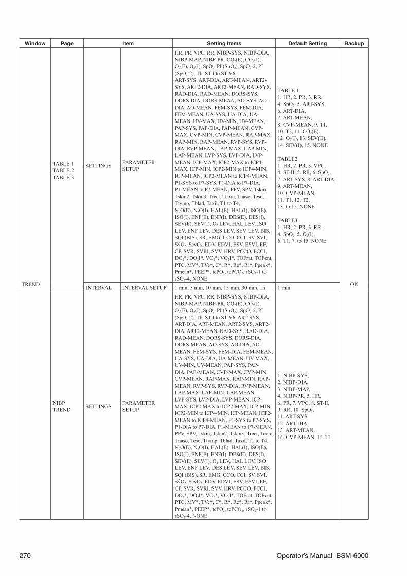
270 Operator’s Manual BSM-6000
Window Page Item Setting Items Default Setting Backup
TREND
TABLE 1TABLE 2TABLE 3
SETTINGS PARAMETER SETUP
HR, PR, VPC, RR, NIBP-SYS, NIBP-DIA, NIBP-MAP, NIBP-PR, CO2(E), CO2(I), O2(E), O2(I), SpO2, PI (SpO2), SpO2-2, PI (SpO2-2), Tb, ST-I to ST-V6, ART-SYS, ART-DIA, ART-MEAN, ART2-SYS, ART2-DIA, ART2-MEAN, RAD-SYS, RAD-DIA, RAD-MEAN, DORS-SYS, DORS-DIA, DORS-MEAN, AO-SYS, AO-DIA, AO-MEAN, FEM-SYS, FEM-DIA, FEM-MEAN, UA-SYS, UA-DIA, UA-MEAN, UV-MAX, UV-MIN, UV-MEAN, PAP-SYS, PAP-DIA, PAP-MEAN, CVP-MAX, CVP-MIN, CVP-MEAN, RAP-MAX, RAP-MIN, RAP-MEAN, RVP-SYS, RVP-DIA, RVP-MEAN, LAP-MAX, LAP-MIN, LAP-MEAN, LVP-SYS, LVP-DIA, LVP-MEAN, ICP-MAX, ICP2-MAX to ICP4-MAX, ICP-MIN, ICP2-MIN to ICP4-MIN, ICP-MEAN, ICP2-MEAN to ICP4-MEAN, P1-SYS to P7-SYS, P1-DIA to P7-DIA, P1-MEAN to P7-MEAN, PPV, SPV, Tskin, Tskin2, Tskin3, Trect, Tcore, Tnaso, Teso, Ttymp, Tblad, Taxil, T1 to T4, N2O(E), N2O(I), HAL(E), HAL(I), ISO(E), ISO(I), ENF(E), ENF(I), DES(E), DES(I), SEV(E), SEV(I), O2 LEV, HAL LEV, ISO LEV, ENF LEV, DES LEV, SEV LEV, BIS, SQI (BIS), SR, EMG, CCO, CCI, SV, SVI, Sv-O2, ScvO2, EDV, EDVI, ESV, ESVI, EF, CF, SVR, SVRI, SVV, HRV, PCCO, PCCI, DO2*, DO2I*, VO2*, VO2I*, TOFrat, TOFcnt, PTC, MV*, TVe*, C*, R*, Re*, Ri*, Ppeak*, Pmean*, PEEP*, tcPO2, tcPCO2, rSO2-1 to rSO2-4, NONE
TABLE 11. HR, 2. PR, 3. RR, 4. SpO2, 5. ART-SYS, 6. ART-DIA, 7. ART-MEAN, 8. CVP-MEAN, 9. T1, 10. T2, 11. CO2(E), 12. O2(I), 13. SEV(E), 14. SEV(I), 15. NONE
TABLE21. HR, 2. PR, 3. VPC, 4. ST-II, 5. RR, 6. SpO2, 7. ART-SYS, 8. ART-DIA, 9. ART-MEAN, 10. CVP-MEAN, 11. T1, 12. T2, 13. to 15. NONE
TABLE31. HR, 2. PR, 3. RR, 4. SpO2, 5. O2(I), 6. T1, 7. to 15. NONE
OKINTERVAL INTERVAL SETUP 1 min, 5 min, 10 min, 15 min, 30 min, 1h 1 min
NIBP TREND SETTINGS PARAMETER
SETUP
HR, PR, VPC, RR, NIBP-SYS, NIBP-DIA, NIBP-MAP, NIBP-PR, CO2(E), CO2(I), O2(E), O2(I), SpO2, PI (SpO2), SpO2-2, PI (SpO2-2), Tb, ST-I to ST-V6, ART-SYS, ART-DIA, ART-MEAN, ART2-SYS, ART2-DIA, ART2-MEAN, RAD-SYS, RAD-DIA, RAD-MEAN, DORS-SYS, DORS-DIA, DORS-MEAN, AO-SYS, AO-DIA, AO-MEAN, FEM-SYS, FEM-DIA, FEM-MEAN, UA-SYS, UA-DIA, UA-MEAN, UV-MAX, UV-MIN, UV-MEAN, PAP-SYS, PAP-DIA, PAP-MEAN, CVP-MAX, CVP-MIN, CVP-MEAN, RAP-MAX, RAP-MIN, RAP-MEAN, RVP-SYS, RVP-DIA, RVP-MEAN, LAP-MAX, LAP-MIN, LAP-MEAN, LVP-SYS, LVP-DIA, LVP-MEAN, ICP-MAX, ICP2-MAX to ICP7-MAX, ICP-MIN, ICP2-MIN to ICP4-MIN, ICP-MEAN, ICP2-MEAN to ICP4-MEAN, P1-SYS to P7-SYS, P1-DIA to P7-DIA, P1-MEAN to P7-MEAN, PPV, SPV, Tskin, Tskin2, Tskin3, Trect, Tcore, Tnaso, Teso, Ttymp, Tblad, Taxil, T1 to T4, N2O(E), N2O(I), HAL(E), HAL(I), ISO(E), ISO(I), ENF(E), ENF(I), DES(E), DES(I), SEV(E), SEV(I), O2 LEV, HAL LEV, ISO LEV, ENF LEV, DES LEV, SEV LEV, BIS, SQI (BIS), SR, EMG, CCO, CCI, SV, SVI, Sv-O2, ScvO2, EDV, EDVI, ESV, ESVI, EF, CF, SVR, SVRI, SVV, HRV, PCCO, PCCI, DO2*, DO2I*, VO2*, VO2I*, TOFrat, TOFcnt, PTC, MV*, TVe*, C*, R*, Re*, Ri*, Ppeak*, Pmean*, PEEP*, tcPO2, tcPCO2, rSO2-1 to rSO2-4, NONE
1. NIBP-SYS, 2. NIBP-DIA, 3. NIBP-MAP, 4. NIBP-PR, 5. HR, 6. PR, 7. VPC, 8. ST-II, 9. RR, 10. SpO2,11. ART-SYS, 12. ART-DIA, 13. ART-MEAN, 14. CVP-MEAN, 15. T1

Operator’s Manual BSM-6000 271
Window Page Item Setting Items Default Setting Backup
TREND HEMO TREND SETTINGS
HR/PR, CO, CI, CCO, CCI, ART-MEAN, PAP-MEAN, PCWP, PCWP TIME, CVP, SV, SVI, LVSW, LVSWI, SVR, SVRI, SVV, PVR, PVRI, RVSW, RVSWI, ScvO2
HR, CO, CI, CCO, CCI, ART-MEAN, PAP-MEAN, PCWP, PCWP TIME, CVP, SV, SVI, LVSW
OK
* Not available for BSM-6000A series.
RECALL Window
Window Page Item Setting Items Default Setting Backup
REC
ALL ARRHYTH
HISTORYARRHYTHMIA EVENT SETUP
ARRHYTHMIA ITEMS
ASYSTOLE, VF, VT, EXT TACHY*1, EXT BRADY*1, V BRADY*1, VPC RUN, SV TACHY*1, TACHYCARDIA, BRADYCARDIA, PAUSE*1, V RHYTHM*1, COUPLET, EARLY VPC, MULTIFORM*1, BIGEMINY, TRIGEMINY*1, VPC, AF*2, IRREGULAR RR*1, PROLONGED RR*1, NO PACER PULSE*1, PACER NON-CAPTURE, ALL
ALL OK
*1 Available only when “EXTENDED” is selected for arrhythmia type on the SYSTEM SETUP window.*2 Not available for BSM-6000K series. Available only when <ARRHYTHMIA TYPE> on the ECG page of the SYSTEM SETUP window is set to
EXTENDED, and <AF DETECTION> on the ECG page of the SYSTEM SETUP window is set to On. For the SYSTEM SETUP window settings, refer to the Administrator’s Guide.
FULL DISC Window
Window Page Item Setting Items Default Setting Backup
FULL
DIS
C
FULL
DIS
C
SETTINGS
DISPLAY/SAVE
DISPLAYED WAVES –
1. TRACE12. NONE3. NONE4. NONE
OK
SAVED WAVES Select from <SELECT THE WAVE TO SAVE AND DISPLAY>
TRACE1, TRACE2, RESP(IMP), SpO2, ART
WAVE-FORMS
SELECT THE WAVE TO SAVE AND DISPLAY
TRACE1, TRACE2, I, II, III, aVR, aVL, aVF, V1 to V6, SpO2, SpO2-2, RESP(IMP), RESP(THM), CO2, CO2(GAS), CO2(EXT), ART, ART2, RAD, DORS, AO, FEM, UA, UV, PAP, CVP, RAP, RVP, LAP, LVP, ICP, ICP2 to ICP4, P1 to P7, EEG1(BIS), EEG2(BIS), FLOW*, Paw*, VOL*, EEG1 to EEG8
TRACE1, TRACE2, RESP(IMP), SpO2, ART
* Not available for BSM-6000A series.
ST Window
Window Page Items Setting Items Default Setting Backup
ST ST INTERVAL SETTINGS
ST POINT ON, OFF ON
OK
ST WAVE ON HOME SCREEN ON, OFF OFF
ST REF WAVE ON HOME SCREEN ON, OFF OFF
LEADTRACE1 to TRACE3, I, II, III, aVR, aVL, aVF, V1 to V6
TRACE1TRACE2TRACE3

272 Operator’s Manual BSM-6000
OCRG Window
Window Page Item Setting Items Default Setting Backup
OCRG OCRG
SETTINGS 1 cm/min, 3 cm/min 1 cm/min
OKSCALE
HR 210-60, 160-80, 220-100 210-60SpO2 100-60, 100-80 100-60RESP (IMP) ×1/4, ×1/2, ×1, ×2, ×4 ×1
aEEG WindowaEEG window is not available for BSM-6301A/K.
Window Page Item Setting Items Default Setting Backup
aEEG aEEG SETTINGS 1, 3, 6, 9, 12 cm/h 6 cm/h OK
ADMIT DISCHARGE Window
Window Page Item Setting Items Default Setting Backup
AD
MIT
DIS
CH
AR
GE
ADMIT
PATIENT TYPE ADULT, CHILD, NEONATE
OR, ICU: ADULTNICU: NEONATE Master
PATIENT ID Up to 16 characters
–
30 min
NAME Up to 15 characters
DATE OF BIRTH254 YEARS 11 MONTHS 30 DAYS before to the present date
AGE (calculated automatically)
0 YEAR 0 MONTH 0 DAY to AGE 254 YEARS 11 MONTHS 30 DAYS
HEIGHT/WEIGHT
HEIGHT0.1 to 299.9 cm0 ft 0.1 in to 9 ft 11.9 in
WEIGHT0.1 to 449.9 kg0.1 to 654.9 lb
BSA (calculated automatically)
Related to input height and weight data
GENDER MALE, FEMALE, – – (blank)
PACEMAKER YES, NO OR, ICU: YESNICU: NO
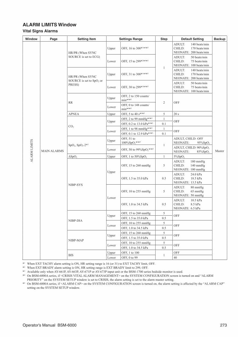
Operator’s Manual BSM-6000 273
ALARM LIMITS WindowVital Signs Alarms
Window Page Setting Item Settings Range Step Default Setting Backup
ALA
RM
LIM
ITS
MAIN ALARMS
HR/PR (When SYNC SOURCE is set to ECG)
Upper OFF, 16 to 300*1*4*5
1
ADULT: 140 beats/minCHILD: 170 beats/minNEONATE: 200 beats/min
Master
Lower OFF, 15 to 299*2*4*5ADULT: 50 beats/minCHILD: 75 beats/minNEONATE: 100 beats/min
HR/PR (When SYNC SOURCE is set to SpO2 or PRESS)
Upper OFF, 31 to 300*1*4*5ADULT: 140 beats/minCHILD: 170 beats/minNEONATE: 200 beats/min
Lower OFF, 30 to 299*2*4*5ADULT: 50 beats/minCHILD: 75 beats/minNEONATE: 100 beats/min
RRUpper OFF, 2 to 150 counts/
min*4*5
2 OFFLower OFF, 0 to 148 counts/
min*4*5
APNEA Upper OFF, 5 to 40 s*4*5 5 20 s
CO2
UpperOFF, 2 to 99 mmHg*4*5 1
OFFOFF, 0.2 to 13.0 kPa*4*5 0.1
LowerOFF, 1 to 98 mmHg*4*5 1
OFFOFF, 0.1 to 12.9 kPa*4*5 0.1
SpO2, SpO2-2*3
Upper OFF, 51 to 100%SpO2*4*5
1
ADULT, CHILD: OFFNEONATE: 95%SpO2
Lower OFF, 50 to 99%SpO2*4*5 ADULT, CHILD: 90%SpO2
NEONATE: 85%SpO2
ΔSpO2 Upper OFF, 1 to 50%SpO2 1 5%SpO2
NIBP-SYS
Upper
OFF, 15 to 260 mmHg 5ADULT: 180 mmHgCHILD: 140 mmHgNEONATE: 100 mmHg
OFF, 1.5 to 35.0 kPa 0.5ADULT: 24.0 kPaCHILD: 18.5 kPaNEONATE: 13.5 kPa
Lower
OFF, 10 to 255 mmHg 5ADULT: 80 mmHgCHILD: 65 mmHgNEONATE: 50 mmHg
OFF, 1.0 to 34.5 kPa 0.5ADULT: 10.5 kPaCHILD: 8.5 kPaNEONATE: 6.5 kPa
NIBP-DIAUpper
OFF, 15 to 260 mmHg 5OFF
OFF, 1.5 to 35.0 kPa 0.5
LowerOFF, 10 to 255 mmHg 5
OFFOFF, 1.0 to 34.5 kPa 0.5
NIBP-MAPUpper
OFF, 15 to 260 mmHg 5OFF
OFF, 1.5 to 35.0 kPa 0.5
LowerOFF, 10 to 255 mmHg 5
OFFOFF, 1.0 to 34.5 kPa 0.5
BISUpper OFF, 1 to 100
1OFF
Lower OFF, 0 to 99 40
*1 When EXT TACHY alarm setting is ON, HR setting range is 16 (or 31) to EXT TACHY limit, OFF.*2 When EXT BRADY alarm setting is ON, HR setting range is EXT BRADY limit to 299, OFF.*3 Available only when AY-661P, AY-663P, AY-671P or AY-673P input unit or the BSM-1700 series bedside monitor is used.*4 On BSM-6000A series, if <CRISIS VITAL ALARM MANAGEMENT> on the SYSTEM CONFIGURATION screen is turned on and “ALARM
PRIORITY” on the SYSTEM SETUP window is set to CRISIS, the alarm setting is set to the alarm master setting.*5 On BSM-6000A series, if <ALARM CAP> on the SYSTEM CONFIGURATION screen is turned on, the alarm setting is affected by the “ALARM CAP”
setting on the SYSTEM SETUP window.

274 Operator’s Manual BSM-6000
Window Page Setting Item Settings Range Step Default Setting Backup
ALA
RM
LIM
ITS
ECG ALARMS
HR/PR
Upper OFF, 16 to 300 beats/min*2*3
1
ADULT: 140 beats/minCHILD: 170 beats/minNEONATE: 200 beats/min
Master
Lower OFF, 15 to 299 beats/min*2*3
ADULT: 50 beats/minCHILD: 75 beats/minNEONATE: 100 beats/min
VPC*1 Upper OFF, 1 to 99 beats/min 1 OFF
ST-I to ST-V6Upper
OFF, –1.99 to 2.00 mV 0.01OFF
OFF, –19.9 to 20.0 mm 0.1
LowerOFF, –2.00 to 1.99 mV 0.01
OFFOFF, –20.0 to 19.9 mm 0.1
PRESS1 ALARMS
P1-SYS to P7-SYSUpper
OFF, –48 to 300 mmHg 2OFF
OFF, –6.0 to 40.0 kPa 0.5
LowerOFF, –50 to 298 mmHg 2
OFFOFF, –6.5 to 39.5 kPa 0.5
P1-DIA to P7-DIAUpper
OFF, –48 to 300 mmHg 2OFF
OFF, –6.0 to 40.0 kPa 0.5
LowerOFF, –50 to 298 mmHg 2
OFFOFF, –6.5 to 39.5 kPa 0.5
P1-MEAN to P7-MEAN
UpperOFF, –48 to 300 mmHg 2
OFFOFF, –6.0 to 40.0 kPa 0.5
LowerOFF, –50 to 298 mmHg 2
OFFOFF, –6.5 to 39.5 kPa 0.5
PRESS2 ALARMS
ART-SYS, ART2-SYS
UpperOFF, –48 to 300 mmHg*3 2
OFFOFF, –6.0 to 40.0 kPa*3 0.5
Lower
OFF, –50 to 298 mmHg*3 2ADULT: 80 mmHgCHILD: 66 mmHgNEONATE: 50 mmHg
OFF, –6.5 to 39.5 kPa*3 0.5ADULT: 10.5 kPaCHILD: 8.5 kPaNEONATE: 6.5 kPa
ART-DIA, ART2-DIAUpper
OFF, –48 to 300 mmHg*3 2OFF
OFF, –6.0 to 40.0 kPa*3 0.5
LowerOFF, –50 to 298 mmHg*3 2
OFFOFF, –6.5 to 39.5 kPa*3 0.5
ART-MEAN, ART2-MEAN
UpperOFF, –48 to 300 mmHg*3 2
OFFOFF, –6.0 to 40.0 kPa*3 0.5
Lower
OFF, –50 to 298 mmHg*3 2ADULT: 60 mmHgCHILD: 46 mmHgNEONATE: 30 mmHg
OFF, –6.5 to 39.5 kPa*3 0.5ADULT: 8.0 kPaCHILD: 6.0 kPaNEONATE: 4.0 kPa
RAD-SYS, AO-SYS, FEM-SYS
UpperOFF, –48 to 300 mmHg 2
OFFOFF, –6.0 to 40.0 kPa 0.5
Lower
OFF, –50 to 298 mmHg 2ADULT: 80 mmHgCHILD: 66 mmHgNEONATE: 50 mmHg
OFF, –6.5 to 39.5 kPa 0.5ADULT: 10.5 kPaCHILD: 8.5 kPaNEONATE: 6.5 kPa
RAD-DIA, AO-DIA, FEM-DIA
UpperOFF, –48 to 300 mmHg 2
OFFOFF, –6.0 to 40.0 kPa 0.5
LowerOFF, –50 to 298 mmHg 2
OFFOFF, –6.5 to 39.5 kPa 0.5
*1 Available only when <ARRHYTHMIA ANALYSIS> on the ECG window is set to ON.*2 On BSM-6000A series, if <CRISIS VITAL ALARM MANAGEMENT> on the SYSTEM CONFIGURATION screen is turned on and “ALARM
PRIORITY” on the SYSTEM SETUP window is set to CRISIS, the alarm setting is set to the alarm master setting.*3 On BSM-6000A series, if <ALARM CAP> on the SYSTEM CONFIGURATION screen is turned on, the alarm setting of HR/PR, ART-SYS, ART-DIA
and ART-MEAN is affected by the “ALARM CAP” setting.

Operator’s Manual BSM-6000 275
Window Page Setting Item Settings Range Step Default Setting Backup
ALA
RM
LIM
ITS
PRESS2 ALARMS
RAD-MEAN, AO-MEAN, FEM-MEAN
UpperOFF, –48 to 300 mmHg 2
OFF
Master
OFF, –6.0 to 40.0 kPa 0.5
Lower
OFF, –50 to 298 mmHg 2ADULT: 60 mmHgCHILD: 46 mmHgNEONATE: 30 mmHg
OFF, –6.5 to 39.5 kPa 0.5ADULT: 8.0 kPaCHILD: 6.0 kPaNEONATE: 4.0 kPa
DORS-SYS
Upper
OFF, –48 to 300 mmHg 2ADULT: OFFCHILD: 200 mmHgNEONATE: OFF
OFF, –6.0 to 40.0 kPa 0.5ADULT: OFFCHILD: 26.5 kPaNEONATE: OFF
Lower
OFF, –50 to 298 mmHg 2ADULT: 80 mmHgCHILD: 66 mmHgNEONATE: 50 mmHg
OFF, –6.5 to 39.5 kPa 0.5ADULT: 10.5 kPaCHILD: 9.0 kPaNEONATE: 6.5 kPa
DORS-DIAUpper
OFF, –48 to 300 mmHg 2 OFFOFF, –6.0 to 40.0 kPa 0.5 OFF
LowerOFF, –50 to 298 mmHg 2 OFFOFF, –6.5 to 39.5 kPa 0.5 OFF
DORS-MEAN
Upper
OFF, –48 to 300 mmHg 2ADULT: OFFCHILD: 186 mmHgNEONATE: OFF
OFF, –6.0 to 40.0 kPa 0.5ADULT: OFFCHILD: 25.0 kPaNEONATE: OFF
Lower
OFF, –50 to 298 mmHg 2ADULT: 60 mmHgCHILD: 46 mmHgNEONATE: 30 mmHg
OFF, –6.5 to 39.5 kPa 0.5ADULT: 8.0 kPaCHILD: 6.0 kPaNEONATE: 4.0 kPa
UA-SYSUpper
OFF, –48 to 300 mmHg 2OFF
OFF, –6.0 to 40.0 kPa 0.5
LowerOFF, –50 to 298 mmHg 2
OFFOFF, –6.5 to 39.5 kPa 0.5
UA-DIAUpper
OFF, –48 to 300 mmHg 2OFF
OFF, –6.0 to 40.0 kPa 0.5
LowerOFF, –50 to 298 mmHg 2
OFFOFF, –6.5 to 39.5 kPa 0.5
UA-MEAN, UV-MEANUpper
OFF, –48 to 300 mmHg 2OFF
OFF, –6.0 to 40.0 kPa 0.5
LowerOFF, –50 to 298 mmHg 2
OFFOFF, –6.5 to 39.5 kPa 0.5
PRESS3 ALARMS
PAP-SYSUpper
OFF, –48 to 300 mmHg* 2OFF
OFF, –6.0 to 40.0 kPa* 0.5
LowerOFF, –50 to 298 mmHg* 2
OFFOFF, –6.5 to 39.5 kPa* 0.5
PAP-DIAUpper
OFF, –48 to 300 mmHg* 2OFF
OFF, –6.0 to 40.0 kPa* 0.5
LowerOFF, –50 to 298 mmHg* 2
OFFOFF, –6.5 to 39.5 kPa* 0.5
PAP-MEAN, CVP-MEANUpper
OFF, –48 to 300 mmHg* 2OFF
OFF, –6.0 to 40.0 kPa* 0.5
LowerOFF, –50 to 298 mmHg* 2
OFFOFF, –6.5 to 39.5 kPa* 0.5
* On BSM-6000A series, if <ALARM CAP> on the SYSTEM CONFIGURATION screen is turned on, the alarm setting is affected by the “ALARM CAP” setting on the SYSTEM SETUP window.

276 Operator’s Manual BSM-6000
Window Page Setting Item Settings Range Step Default Setting Backup
ALA
RM
LIM
ITS
PRESS3 ALARMS
RVP-SYS, LVP-SYSUpper
OFF, –48 to 300 mmHg 2OFF
Master
OFF, –6.0 to 40.0 kPa 0.5
LowerOFF, –50 to 298 mmHg 2
OFFOFF, –6.5 to 39.5 kPa 0.5
RVP-DIA, LVP-DIAUpper
OFF, –48 to 300 mmHg 2OFF
OFF, –6.0 to 40.0 kPa 0.5
LowerOFF, –50 to 298 mmHg 2
OFFOFF, –6.5 to 39.5 kPa 0.5
RAP-MEAN, RVP-MEAN, LAP-MEAN, LVP-MEAN, ICP-MEAN, ICP2-MEAN to ICP4-MEAN
UpperOFF, –48 to 300 mmHg 2
OFFOFF, –6.0 to 40.0 kPa 0.5
LowerOFF, –50 to 298 mmHg 2
OFFOFF, –6.5 to 39.5 kPa 0.5
TEMP ALARMS
T1 to T4, Tskin, Tskin2, Tskin3, Trect, Tcore, Tnaso, Teso, Ttymp
Upper
OFF, 0.1 to 45.0°C 0.1ADULT: 38.0°CCHILD: 38.5°CNEONATE: 39.0°C
OFF, 33.0 to 113.0°F 1.0ADULT: 100°FCHILD: 101°FNEONATE: 102°F
LowerOFF, 0.0 to 44.9°C 0.1
OFFOFF, 32.0 to 112.0°F 1.0
Tblad, TaxilUpper
OFF, 0.1 to 45.0°C 0.1ADULT: 38.0°CCHILD: 38.5°CNEONATE: 39.0°C
OFF, 33.0 to 113.0°F 1.0ADULT: 100°FCHILD: 101°FNEONATE: 102°F
LowerOFF, 0.0 to 44.9°C 0.1
OFFOFF, 32.0 to 112.0°F 1.0
TbUpper
OFF, 15.1 to 45.0°C 0.1ADULT: 38.0°CCHILD: 38.5°CNEONATE: 39.0°C
OFF, 51.0 to 113.0°F 1.0ADULT: 100°FCHILD: 101°FNEONATE: 102°F
LowerOFF, 15.0 to 44.9°C 0.1
OFFOFF, 50.0 to 112.0°F 1.0
ΔT, ΔT2 UpperOFF, 0.1 to 45.0°C 0.1
OFFOFF, 1.0 to 113.0°F 1.0
GAS ALARMS
RRUpper OFF, 2 to 150 counts/
min*1*2
2OFF
Lower OFF, 0 to 148 counts/min*1*2 OFF
APNEA Upper OFF, 5 to 40 s*1*2 5 20 s
CO2(E)Upper
OFF, 2 to 99 mmHg*1*2 1OFF
OFF, 0.2 to 13.0 kPa*1*2 0.1
LowerOFF, 1 to 98 mmHg*1*2 1
OFFOFF, 0.1 to 12.9 kPa*1*2 0.1
CO2(I) Upper
OFF, 1 to 99 mmHg 1
ADULT OR, CHILD: 3 mmHgADULT ICU/NICU, NEONATE: OFF
OFF, 0.1 to 12.9 kPa 0.1ADULT OR, CHILD: 0.4 kPaADULT ICU/NICU, NEONATE: OFF
O2(E)Upper OFF, 11 to 100%
1OFF
Lower OFF, 10 to 99% OFF
O2(I)Upper OFF, 19 to 100%
1OFF
Lower 18 to 99% 18%
*1 On BSM-6000A series, if <CRISIS VITAL ALARM MANAGEMENT> on the SYSTEM CONFIGURATION screen is turned on and “ALARM PRIORITY” on the SYSTEM SETUP window is set to CRISIS, the alarm setting is set to the alarm master setting.
*2 On BSM-6000A series, if <ALARM CAP> on the SYSTEM CONFIGURATION screen is turned on, the alarm setting is affected by the “ALARM CAP” setting on the SYSTEM SETUP window.

Operator’s Manual BSM-6000 277
Window Page Setting Item Settings Range Step Default Setting Backup
ALA
RM
LIM
ITS
GAS ALARMS
N2O(E)Upper OFF, 1 to 100%
1OFF
Master
Lower OFF, 0 to 99% OFF
N2O(I)Upper OFF, 1 to 100%
180%
Lower OFF, 0 to 99% OFF
HAL(E)Upper OFF, 0.1 to 7.0%
0.1OFF
Lower OFF, 0.0 to 6.9% OFF
HAL(I)Upper OFF, 0.1 to 7.0%
0.14.0%
Lower OFF, 0.0 to 6.9% OFF
ISO(E)Upper OFF, 0.1 to 7.0%
0.1OFF
Lower OFF, 0.0 to 6.9% OFF
ISO(I)Upper OFF, 0.1 to 7.0%
0.15.0%
Lower OFF, 0.0 to 6.9% OFF
ENF(E)Upper OFF, 0.1 to 7.0%
0.1OFF
Lower OFF, 0.0 to 6.9% OFF
ENF(I)Upper OFF, 0.1 to 7.0%
0.15.0%
Lower OFF, 0.0 to 6.9% OFF
SEV(E)Upper OFF, 0.1 to 7.0%
0.1OFF
Lower OFF, 0.0 to 6.9% OFF
SEV(I)Upper OFF, 0.1 to 7.0%
0.16.0%
Lower OFF, 0.0 to 6.9% OFF
DES(E)Upper OFF, 0.1 to 20.0%
0.1OFF
Lower OFF, 0.0 to 19.9% OFF
DES(I)Upper OFF, 0.1 to 20.0%
0.112.0%
Lower OFF, 0.0 to 19.9% OFF
OTHER ALARMS
MV*Upper OFF, 0.1 to 30.0 L/min
0.1
ADULT: 10.0CHILD: 6.0NEONATE: OFF
Lower OFF, 0.0 to 29.9 L/min ADULT, CHILD: 2.0NEONATE: OFF
Ppeak*Upper OFF, 1 to 100 cmH2O
1
ADULT, CHILD: 40NEONATE: OFF
Lower OFF, 0 to 99 cmH2OADULT, NEONATE: OFFCHILD: 8
PEEP*Upper OFF, 1 to 50 cmH2O
1
ADULT, CHILD: 10NEONATE: OFF
Lower OFF, 0 to 49 cmH2OADULT, CHILD: 2NEONATE: OFF
SEFUpper OFF, 1.0 to 60.0 Hz
0.5OFF
Lower OFF, 0.5 to 59.5 Hz OFF
TPUpper OFF, 0.02 to 9.99 nW
0.01OFF
Lower OFF, 0.01 to 9.98 nW OFF
CCO*Upper OFF, 1.1 to 20.0 L/min
0.1
OFFLower OFF, 1.0 to 19.9 L/min OFF
CCI*Upper OFF, 1.1 to 20.0
L/min/m2 OFF
Lower OFF, 1.0 to 19.9 L/min/m2 OFF
* Not available for BSM-6000A series.

278 Operator’s Manual BSM-6000
Arrhythmia Alarms
Window Page Setting Item Settings Range Step Default Setting Backup
AR
RH
YTH
ALA
RM
S
ARRHYTH
ASYSTOLE ON fixed3 to 10 s 1 ADULT, CHILD: 5 s
NEONATE: 3 s
Master
VF ON fixed – ON
VT*1
ON fixed – ON
V BRADY alarm limit to 300 bpm 1
ADULT, CHILD: 100 bpmNEONATE: 140 bpm
Value set in VPC RUN to 9 beats 1 6 beats
EXT TACHY*1
ON, OFF – BSM-6000A: ONBSM-6000K: OFF
Upper heart rate alarm limit to 300 bpm 1
ADULT: 160 bpmCHILD: 190 bpmNEONATE: 220 bpm
EXT BRADY*1
ON, OFF – BSM-6000A: ONBSM-6000K: OFF
15 to lower heart rate alarm limit 1
ADULT: 40 bpmCHILD: 60 bpmNEONATE: 80 bpm
V BRADY*1
ON, OFF –ADULT OR: OFF ICU/NICU: ONCHILD, NEONATE: OFF
15 to 299 bpm 1 ADULT, CHILD: 50 bpmNEONATE: 60 bpm
VPC RUN
ON, OFF –ADULT OR: OFF ICU/NICU: ONCHILD, NEONATE: OFF
16 to 300 bpm*1 1ADULT, CHILD: 100 bpmNEONATE: 140 bpm
3 to 8 beats 1 3 beats
SV TACHY*1
ON, OFF – OFF
16 to 300 bpm 1ADULT, CHILD: 170 bpmNEONATE: 210 bpm
3 to 9 beats 1 6 beats
PAUSE*1
ON, OFF – ON
1.0 to 3.0 s 0.1 ADULT, CHILD: 3.0 sNEONATE: 1.5 s
V RHYTHM*1 ON, OFF –ADULT OR: OFF ICU/NICU: ONCHILD, NEONATE: OFF
COUPLET ON, OFF – OFFEARLY VPC ON, OFF – OFFMULTIFORM*1 ON, OFF – OFFBIGEMINY ON, OFF – OFFTRGEMINY*1 ON, OFF – OFF
AF*2 ON, OFF – ADULT: ONCHILD, NEONATE: OFF
IRREGULAR RR*1 ON, OFF – OFFPROLONGED RR*1 ON, OFF – OFFNO PACER PULSE*1 ON, OFF – OFF
PACER NON-CAPTURE*1ON, OFF – OFF40 to 480 ms 4 400 ms
*1 Available only when “EXTENDED” is selected for arrhythmia type on the SYSTEM SETUP window.*2 Not available for BSM-6000K series. Available only when <ARRHYTHMIA TYPE> on the ECG page of the SYSTEM SETUP window is set to
EXTENDED, and <AF DETECTION> on the ECG page of the SYSTEM SETUP window is set to On. For the SYSTEM SETUP window settings, refer to the Administrator’s Guide.

Operator’s Manual BSM-6000 279
DATE Window
Window Page Item Setting Items Default Setting Backup
DATE DATE
YEAR 2000 to 2099
– OK
MONTH 1 to 12
DAY 1 to 31
HOUR 0 to 23
MINUTE 0 to 59
VOLUME Window
Window Page Item Setting Items Default Setting Backup
VOLUME VOLUMESYNC SOUND VOLUME
ON, OFF ON
OK0 to 7 (8 steps) 3
ALARM VOLUME 1 to 7 (7 steps) 5
DISPLAY Window
Window Page Item Setting Items Default Setting Backup
DISPLAY
BRIGHT BRIGHTNESS 0 to 7 (8 steps) 7
OKWAVES
NO.ECG WAVES 1, 2, 3 1
PRESS SCALE SEPARATE, COMMON, DUAL COMMON
SWEEP SPEED 6 mm/s, 12.5 mm/s, 25 mm/s, 50 mm/s 25 mm/s
RESP/CO2 SWEEP SPEED 1 mm/s, 6 mm/s, 12.5 mm/s, 25 mm/s
OR: 6 mm/sICU: 25 mm/sNICU: 1 mm/s
WAVE DISPLAYSpO2, SpO2-2, EEG, EEG2, FLOW*, Paw*, VOL*, P1 to P7
All
* Not available for BSM-6000A series.
RECORD Window
Window Page Item Setting Items Default Setting Backup
RECORD
REC PARAMS TRACES
ECG, ECG2, ECG3, RESP, SpO2, SpO2-2, measuring PRESS labels, CO2, O2, N2O, AGENT1, AGENT2, FLOW*, Paw*, VOL*, EEG1 (BIS), EEG2 (BIS), FLOW(EXT), Paw(EXT), NONE
TRACE 1: ECGTRACE 2: NONETRACE 3: NONE
OK
OTHER
ALARM RECORDING ON, OFF OFF
RECORDING SPEED 12.5 mm/s, 25 mm/s, 50 mm/s 25 mm/s
PERIODIC REC INTERVAL (min)
OFF, FREE, 30, 60, 120, 5(OCRG), 15(OCRG) OFF
* Not available for BSM-6000A series.

280 Operator’s Manual BSM-6000
ECG Window
Window Page Item Setting Items Default Setting Backup
ECG
MAIN
SENSITIVITY ×1/4, ×1/2, AUTO, ×1, ×2, ×4 ×1OK
LEAD I, II, III, aVR, aVL, aVF, V1 to V6 II
ALARMS
HR/PR
The setting items and default setting are the same as the ALARM LIMITS setting in ECG ALARMS page.
Master
VPC
ST
ST ALARMS ALARMS ST-I to ST-V6
ARRHYTH The item, setting items and default setting are the same as the ALARM LIMITS setting in ARRHYTH ALARMS page.
OTHER
FILTERS– DIAG, MONITOR,
MAXIMUMOR, NICU: MAXIMUM ICU: MONITOR
OKHUM FILTER ON, OFF OFF
HR DISPLAY MODE AVERAGE, INSTANT AVERAGE
AUTO LEAD CHANGE ON, OFF OFF
PACINGDETECT ON, OFF ADULT, CHILD: ON
NEONATE: OFF 30 min
MARK ON, OFF OFF
OK
NUMBER OF ELECTRODES STANDARD, INDIV 6, INDIV 10 STANDARD
ECG MEASUREMENT ON, OFF ON
SYNC PITCH FIXED, PRESS, SpO2, SpO2-2 FIXED
SYNC SOURCE– ECG, PRESS, SpO2 ECG
PR DISPLAY ON, OFF OFF
ARRHYTH ANALYSIS
ARRHYTHMIA ANALYSIS ON, OFF ON Master
ARRHYTHMIA ANALYSIS METHOD SINGLE, MULTIPLE SINGLE OK
QRS DETECTION TYPE ADULT, CHILD, NEONATE OR, ICU: ADULTNICU: NEONATE Master
ECG2/3 WAVES
NO. ECG WAVES 1, 2, 3 1
OK
ECG2 SENSITIVITY ×1/4, ×1/2, ×1, ×2, ×4 ×1
ECG2 LEAD I, II, III, aVR, aVL, aVF, V1 to V6 V4
ECG3 SENSITIVITY ×1/4, ×1/2, ×1, ×2, ×4 ×1
ECG3 LEAD I, II, III, aVR, aVL, aVF, V1 to V6 V5
V-LEADSFREE LEAD a (Ca/Va) V1 to V6 V4
FREE LEAD b (Cb/Vb) V1 to V6 V5
ST POINT
ISO POINT R –: 248 to 0 ms ADULT: 80 msCHILD, NEONATE: 56 ms
30 minJ POINT R +: 0 to 340 ms ADULT: 48 msCHILD NEONATE: –
ST POINT R +: 0 to * ms 60 ms
* When J point is set to R +: 340 ms, ST point is J + 0 ms.

Operator’s Manual BSM-6000 281
RESP/CO2 Window
Window Page Item Setting Items Default Setting Backup
RESP/CO2
MAIN
IMPEDANCE RESP LEAD R-L, R-F R-FOK
SENSITIVITY ×1/4, ×1/2, ×1, ×2, ×4 ×1
ALARMS
RR The setting items and default setting are the same as the ALARM LIMITS setting in MAIN ALARMS page. MasterAPNEA
CO2
SCALE CO2
–0-40, 0-60, 0-80, 0-120, 0-150 mmHg or 0 (fixed) to 150 mmHg
0-40 mmHg
OK
–0.0-5.5, 0.0-8.0, 0.0-10.5, 0.0-16.0, 0.0-20.0 kPaor 0.0 (fixed) to 20.0 kPa
0.0-5.5 kPa
GAS COMP GAS COMPOSITION
– AIR, O2+AIR, O2+N2OOR: O2+N2OICU, NICU: O2+AIR
OKPERCENTAGE OF INSPIRED O2
0 to 100% 21.0%
OTHER
IMPEDANCE MEASUREMENT ON, OFF OR: OFFICU, NICU: ON
OKRESP/CO2 SWEEP SPEED 1 mm/s, 6 mm/s, 12.5 mm/s,
25 mm/s
OR: 6 mm/sICU: 25 mm/sNICU: 1 mm/s
ETCO2 MAX HOLD 10 s, 20 s, OFF 10 s
DISPLAY IMP-RR AS SECOND PARAMETER ON, OFF OFF
SpO2 Window
Window Page Item Setting Items Default Setting Backup
SpO2
MAIN
SpO2
SENSITIVITY ×1/8, ×1/4, ×1/2, ×1, AUTO, ×2, ×4, ×8 AUTO OK
ALARMSSpO2 The setting items and default setting are the same as the
ALARM LIMITS setting in MAIN ALARMS page. MasterHR/PR
SpO2-2*1
SENSITIVITY ×1/8, ×1/4, ×1/2, ×1, AUTO, ×2, ×4, ×8 AUTO OK
ALARMSSpO2-2 The setting items and default setting are the same as the
ALARM LIMITS setting in MAIN ALARMS page. MasterΔSpO2
OTHER
SYNC SOURCE– ECG, PRESS, SpO2 ECG
OK
PR DISPLAY ON, OFF OFF
SYNC PITCH FIXED, PRESS, SpO2, SpO2-2 FIXED
RESPONSE*2 FAST, NORMAL, SLOW NORMAL
PARAMETER FOR 2ND CURRENT TREND OFF, PI OFF
AVERAGE TIME(S)*3 2, 4, 8, 10, 12, 14, 18 8
SENSITIVITY MODE*3 MAX, NORMAL, APOD NORMAL
SpO2 SENSITIVITY MODE*2 MAX, NORMAL NORMAL30 min
SpO2-2 SENSITIVITY MODE*6 MAX, NORMAL NORMAL
FAST SAT*3 ON, OFF OFF OK
NUMERIC DISPLAY
NUMERIC DISPLAY ON HOME SCREEN FOR SpO2*4
PR ON, OFF OFF
OK
PI*5 ON, OFF OFFSQI*6 ON, OFF OFF
NUMERIC DISPLAY ON HOME SCREEN FOR SpO2-2
PR*7 ON, OFF OFFΔSpO2 ON, OFF OFFPI*5 ON, OFF OFF
*1 SpO2-2 page is displayed when a JL-500P1 or JL-500P2 SpO2 adapter is connected to an AY-661P, AY-663P, AY-671P or AY-673P input unit or BSM-1763 or BSM-1773 bedside monitor, or an IF-919P or IF-925P communication cable is used. The PR alarm setting is not available when the IF-919P or IF-925P communication cable is used. The JL-500P2 SpO2 adapter, AY-660P, AY-661P and AY-663P input units, and BSM-1763 bedside monitor are not available for BSM-6000A series.

282 Operator’s Manual BSM-6000
*2 Available only when an AY-660P, AY-661P, AY-663P, AY-671P or AY-673P input unit or BSM-1763 or BSM-1773 bedside monitor is used.*3 Available only when an AY-631P or AY-633P input unit or BSM-1700 series bedside monitor is used.*4 Available only when an AY-631P, AY-633P, AY-660P, AY-661P, AY-663P, AY-671P or AY-673P input unit or BSM-1700 series bedside monitor is used.*5 Available only when an AY-631P, AY-633P, AY-660P, AY-661P, AY-663P, AY-671P or AY-673P input unit or BSM-1700 series bedside monitor, or IF-925P
communication cable is used.*6 Available only when the SpO2 module version is 02-01 or later, the bedside monitor software version is 05-01 or later, and the AY-600P series input unit
version 02-01 or later.*7 Available only when an JL-500P1 or JL-500P2 SpO2 adapter is connected to the AY-661P, AY-663P, AY-671P or AY-673P input unit or BSM-1763 or
BSM-1773 bedside monitor.
NIBP Window
Window Page Item Setting Items Default Setting Backup
NIBP
MAIN
INITIAL CUFF PRESSURE TYPE ADULT, CHILD, NEONATEADULT: ADULTCHILD: CHILDNEONATE: NEONATE
30 min
MEASUREMENT INTERVAL
MANUAL, STAT, SIM, 1 min, 2 min, 2.5 min, 5 min, 10 min, 15 min, 30 min, 1 h, 2 h, 4 h, 8 h
MANUAL
Master
ALARMS
SYSThe setting items and default setting are the same as the ALARM LIMITS setting in MAIN ALARMS page.DIA
MAP
PWTT*1 PWTT MEASUREMENT ON, OFF OFF OK
OTHER
INITIAL CUFF PRESSURE
ADULT100 to 280 mmHg 180 mmHg
–
13.0 to 37.0 kPa 24.0 kPa
CHILD100 to 280 mmHg 140 mmHg
13.0 to 37.0 kPa 19.0 kPa
NEONATE70 to 145 mmHg 100 mmHg
9.0 to 19.0 kPa 13.0 kPa
DISPLAY OSCILLATION GRAPH ON, OFF ONOK
INFLATE MODE*1, *2 ON, OFF OFF
*1 Not available for BSM-6000A series.*2 Available only when an Inflate Mode (iNIBP) compatible input unit is mounted.

Operator’s Manual BSM-6000 283
PRESS Window
Window Page Item Setting Items Default Setting Backup
PRESS
MAIN ALARMS
SYSThe setting items and default setting are the same as the PRESS1 to PRESS3 ALARMS settings of ALARM LIMITS in MAIN ALARMS page.
MasterDIAMEANHR/PR
SCALE
ART, ART2, RAD, DORS, AO, LVP, FEM, P1 to P7
–
0-20, 0-50, 0-100, 0-160, 0-200, 0-300 mmHg or 0 to 300 mmHg
ADULT: 0-200 mmHgCHILD: 0-160 mmHgNEONATE: 0-100 mmHg
30 min0.0-2.5, 0.0-6.5, 0.0-13.5, 0.0-21.5, 0.0-26.5, 0.0-40.0 kPa or 0.0 to 40.0 kPa
ADULT: 0.0-26.5 kPaCHILD: 0.0-21.5 kPaNEONATE: 0.0-13.5 kPa
UA –
0-20, 0-50, 0-100, 0-160, 0-200, 0-300 mmHg or 0 to 300 mmHg
0-100 mmHg
OK
0.0-2.5, 0.0-6.5, 0.0-13.5, 0.0-21.5, 0.0-26.5, 0.0-40.0 kPa or 0.0 to 40.0 kPa
0.0-13.5 kPa
PAP, CVP, RAP, UV, RVP, LAP, ICP ICP2 to ICP4
–
0-20, 0-50, 0-100, 0-160, 0-200, 0-300 mmHg or 0 to 300 mmHg
0-50 mmHg
0.0-2.5, 0.0-6.5, 0.0-13.5, 0.0-21.5, 0.0-26.5, 0.0-40.0 kPa or 0.0 to 40.0 kPa
0.0-6.5 kPa
PRESS
LABEL SELECTABLE ITEMS
P1 to P7, ART, ART2, RAD, DORS, AO, FEM, UA, UV, PAP, CVP, RAP, RVP, LAP, LVP, ICP, ICP2 to ICP4
– – –
OTHER
SYNC SOURCE
– ECG, PRESS, SpO2 ECG
OK
PR DISPLAY ON, OFF OFFCALCULATION METHOD STANDARD, PEAK STANDARDCPP DISPLAY ON, OFF OFFSYNC PITCH FIXED, PRESS, SpO2, SpO2-2 FIXED
PRESS SCALE SEPARATE, COMMON, DUAL COMMON
NUMERIC DISPLAY
ART, ART2, RAD, DORS, AO, FEM, PAP, RVP, LVP, P1 to P7
SYS/DIA (MEAN), MEAN SYS/DIA (MEAN)
UAMAX/MIN (MEAN), MEAN
MAX/MIN (MEAN)UV, CVP, RAP, LAP, ICP, ICP2 to ICP4 MEAN
PPV/SPV DISPLAY PPV, SPV, OFF OFFPPV/SPV AVERAGE TIME 1 min, 5 min 1 minCVP AUTO ET MODE ON, OFF OFF

284 Operator’s Manual BSM-6000
TEMP Window
Window Page Item Setting Items Default Setting Backup
TEMP
MAIN ALARMS Measuring label, ΔT, ΔT2
The setting items and default setting are the same as the ALARM LIMITS setting in TEMP ALARMS page. Master
LABEL SELECTABLE ITEMS
T1 to T4, Tskin, Tskin2, Tskin3, Tcore, Tnaso, Teso, Tblad, Trect, Ttymp, Taxil, Tb, NONE
– –
OTHER
ΔT SITES
T1 to T4, Tskin, Tskin2, Tskin3, Tcore, Tnaso, Teso, Tblad, Trect, Ttymp, Taxil, Tb, NONE
T1 – T2
OK
ΔT2 SITES
T1 to T4, Tskin, Tskin2, Tskin3, Tcore, Tnaso, Teso, Tblad, Trect, Ttymp, Taxil, Tb, NONE
T3 – T4
BIS Window
Window Page Item Setting Items Default Setting Backup
BIS
MAINSENSITIVITY 10, 20, 30, 50, 70, 100, 150,
200 30 OK
ALARMS BIS The setting items and default setting are the same as the ALARM LIMITS setting in MAIN ALARMS page. Master
OTHER
FILTER ON, OFF ONOK
SMOOTHING RATE 10 s, 15 s, 30 s 15 s
AUTO CHECK ON, OFF ON 30 min
EEG SWEEP SPEED 6 mm/s, 12.5 mm/s, 25 mm/s, 50 mm/s 25 mm/s
OKPARAMETER FOR 2ND CURRENT TREND OFF, EMG, SQI, SR EMG
CO Window
Window Page Item Setting Items Default Setting Backup
CO
CATHETER
CATHETER Edwards, Argon, CONSTANT Edwards
OK
INJECTATE TEMPERATURE MEASURING METHOD BATH, INLINE BATH
INJECTATE VOLUME 10 cc, 5 cc, 3 cc 10 cc
CATHETER SIZEEdwards 8 F, 7.5 F, 7 F, 6 F, 5.5 F
7.5 FArgon 7.5 F, 7 F, 6 F, 5 F
CONSTANT 0.001 to 1.000 0.564
HEIGHT/WEIGHT
HEIGHT0.0 to 299.9 cm
– –0.1 to 118.0 inch (9 ft 11.9 inch)
WEIGHT0.00 to 449.9 kg
0.1 to 654.9 pound
ALARMS Tb The setting items and default setting are the same as the ALARM LIMITS setting in TEMP ALARMS page. Master

Operator’s Manual BSM-6000 285
GAS Window
Window Page Item Setting Items Default Setting Backup
GAS
SCALE
CO2
– 0-40, 0-60, 0-80, 0-120, 0-150 mmHg or 0 (fixed) to 150 mmHg 0-40 mmHg
OK
– 0.0-5.5, 0.0-8.0, 0.0-10.5, 0.0-16.0, 0.0-20.0 kPa or 0.0 (fixed) to 20.0 kPa 0.0-5.5 kPa
O2 – 30-60, 0-60, 0-100% or 0 to 100% 0-100%
N2O – 0-80, 0-100, 50-80% or 0 to 100% 50-80%
HAL, ISO, ENF, SEV, DES
– 0.0-4.0, 0.0-8.0, 0.0-20.0 mmHg or 0.0 to 20.0 mmHg 0.0-8.0 mmHg
ALARMS*1
RR, APNEA, CO2(E), CO2(I), O2(E), O2(I), N2O(E), N2O(I), HAL(E), HAL(I), ISO(E), ISO(I), ENF(E), ENF(I), SEV(E), SEV(I), DES(E), DES(I)
The setting items and default setting are the same as the ALARM LIMITS settings in GAS ALARMS page.
Master
SAMPLING*1*2
SAMPLING MODE AUTO, MANUAL AUTO
–SAMPLING VOLUME
ADULT: 120 to 200 mL/minNEONATE: 70 to 120 mL/min
ADULT: 120 mL/minNEONATE: 70 mL/min
OTHER
NUMERIC DISPLAYO2(E), O2(I), N2O(E), N2O(I), AGENT1(E), AGENT1(I), AGENT2(E), AGENT2(I), MAC, NONE
RR (fixed), CO2(E) (fixed), O2(I), AGENT1(I), NONE OK
CO2(I) DISPLAY ON, OFF OFF
GAS MEASUREMENT*3 ON, OFF ON
*1 The ALARMS and SAMPLING page are not displayed when an anesthetic machine is connected.*2 SAMPLING page is not displayed when the GF-210R multigas unit or GF-220R multigas/flow unit is connected to the monitor.*3 Available only when a GF-110PA or GF-210R multigas unit or GF-120PA or GF-220R multigas/flow unit is used.

286 Operator’s Manual BSM-6000
O2 Window
Window Page Item Setting Items Default Setting Backup
O2 MAIN ALARMS O2(I)The setting items and default setting are the same as the ALARM LIMITS settings in GAS ALARMS page. Master
VENT Window
Window Page Item Setting Items Default Setting Backup
VENT
SCALE
Paw – 0-10, 0-20, 0-50, 0-100, 0-150 or 0 (fixed) to 150 0-50
OK
FLOW – −1.0-+1.0, −2.0-+2.0, −3.0-+3.0 or –3.0-+3.0 -1.0-+1.0
VOL*1 – 0-150, 0-300, 0-500, 0-1000, 0-2000 0-500
LOOP*2
P-VPaw 0-10, 0-20, 0-30, 0-50, 0-100 0-30
VOL 0-150, 0-300, 0-500, 0-800, 0-1000, 0-2000 0-800
F-VFLOW −0.3-+0.3, −0.5-+0.5, −1.0-+1.0,
−1.5-+1.5, −3.0-+3.0 −1.5-+1.5
VOL 0-150, 0-300, 0-500, 0-800, 0-1000, 0-2000 0-800
SETTINGS SHOW LOOPS ON HOME SCREEN P-V, F-V, OFF P-V
OTHER NUMERIC DISPLAYPmean, MV, PEEP, O2(I), Ppeak, set O2(I), TV, set Freq, set AMP, set SV, MAP, %Leak, AMP, NONE
MV, TV, O2(I), Pmean
*1 Available only when using the IF-928P, IF-938P or IF-943P communication cable.*2 Available only when using the IF-943P communication cable or connecting Metran R100 with the IF-938P communication cable.
CCO Window
Window Page Item Setting Items Default Setting Backup
CCO
PATIENT INFO
DATE OF BIRTHThe setting items and default setting are the same as the settings in PATIENT INFO window. OKHEIGHT/WEIGHT
GENDER
MAIN ALARMSCCO The setting items and default setting are the same as the
ALARM LIMITS settings in OTHER ALARMS page. MasterCCI
WAVEFORM SCALE 0-20, 0-50, 0-100, 0-160, 0-200, 0-300 0-200
OK
OTHER
NUMERIC DISPLAY CCO, CCI, SV, SVI, SVR, SVRI, SVV, NONE
CCO, NONE, NONE, NONE
PARAMETER FOR CURRENT TREND CCO, CCI CCO
AVERAGE TIME 20 s, 5 min 20 s
CCO(CCO, CCO/SvO2)
OTHER NUMERIC DISPLAY CCO, SVRI, SvO2, Tb, EF, ScvO2, CCI, EDV, SVR, EDVI, NONE CCO, SVR, EF, Tb
CCO(PiCCO) OTHER NUMERIC DISPLAY ABSOLUTE, INDEX INDEX
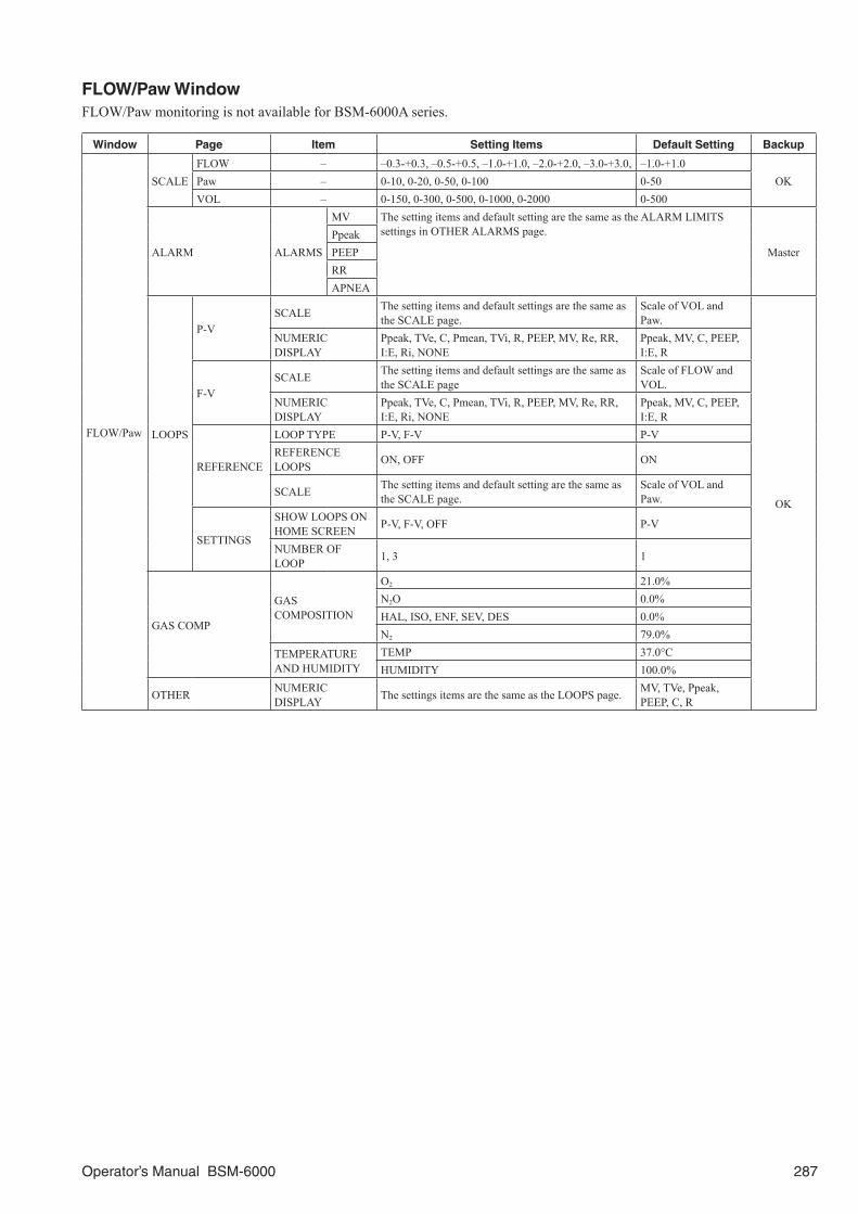
Operator’s Manual BSM-6000 287
FLOW/Paw WindowFLOW/Paw monitoring is not available for BSM-6000A series.
Window Page Item Setting Items Default Setting Backup
FLOW/Paw
SCALEFLOW – –0.3-+0.3, –0.5-+0.5, –1.0-+1.0, –2.0-+2.0, –3.0-+3.0, –1.0-+1.0
OKPaw – 0-10, 0-20, 0-50, 0-100 0-50VOL – 0-150, 0-300, 0-500, 0-1000, 0-2000 0-500
ALARM ALARMS
MV The setting items and default setting are the same as the ALARM LIMITS settings in OTHER ALARMS page.
MasterPpeakPEEPRRAPNEA
LOOPS
P-VSCALE The setting items and default settings are the same as
the SCALE page.Scale of VOL and Paw.
OK
NUMERIC DISPLAY
Ppeak, TVe, C, Pmean, TVi, R, PEEP, MV, Re, RR, I:E, Ri, NONE
Ppeak, MV, C, PEEP, I:E, R
F-VSCALE The setting items and default settings are the same as
the SCALE pageScale of FLOW and VOL.
NUMERIC DISPLAY
Ppeak, TVe, C, Pmean, TVi, R, PEEP, MV, Re, RR, I:E, Ri, NONE
Ppeak, MV, C, PEEP, I:E, R
REFERENCE
LOOP TYPE P-V, F-V P-VREFERENCE LOOPS ON, OFF ON
SCALE The setting items and default setting are the same as the SCALE page.
Scale of VOL and Paw.
SETTINGS
SHOW LOOPS ON HOME SCREEN P-V, F-V, OFF P-V
NUMBER OF LOOP 1, 3 1
GAS COMP
GAS COMPOSITION
O2 21.0%N2O 0.0%HAL, ISO, ENF, SEV, DES 0.0%N2 79.0%
TEMPERATURE AND HUMIDITY
TEMP 37.0°CHUMIDITY 100.0%
OTHER NUMERIC DISPLAY The settings items are the same as the LOOPS page. MV, TVe, Ppeak,
PEEP, C, R

288 Operator’s Manual BSM-6000
EEG Window
Window Page Item Setting Items Default Setting Backup
EEG
MEASURE SENSITIVITY 1, 2, 3, 5, 7, 10, 15, 20, 30, 50, 75, 100, 150, 200 µV/mm 10 µV/mm OK
ALARM ALARMSSEF The setting items and default setting are the same as the
ALARM LIMITS settings in OTHER ALARMS page. Master TP
CSA SCALE
VOLTAGE SPECTRUM 0.2, 0.5, 1, 2, 5, 10, 20, 50, 100, 200, 500, 1000, 2000 μV 200 μV
OK
POWER SPECTRUM 1, 2, 5, 10, 20, 50, 100, 200, 500, 1000, 2000, 5000 pW 1000 pW
FREQUENCY 0-15, 0-30, 0-60 Hz 0-30 Hz
DSA SCALE
VOLTAGE SPECTRUM 0.2, 0.5, 1, 2, 5, 10, 20, 50, 100, 200, 500, 1000, 2000 μV 200 μV
POWER SPECTRUM 1, 2, 5, 10, 20, 50, 100, 200, 500, 1000, 2000, 5000 pW 1000 pW
FREQUENCY 0-15, 0-30, 0-60 Hz 0-30 HzDSA COLOR SCALE Type 1, Type 2 Type 1
MONTAGE
IMP CHECK IMPEDANCE THRESHOLD 2, 5, 10, 20, 50 kΩ 10 kΩ
OTHER
1 10 ELECTRODES
ELECTRODE POSITION
A1, A2, T3, T4, T5, T6, F7, F8, F3, F4, Fz, Fp1, Fp2, C3, C4, Cz, P3, P4, Pz, O1, O2, Oz
1-A1, 2-A2, 3-F3, 4-F4, 5-C3, 6-C4, 7-P3, 8-P4, 9-O1, 10-O2
MONTAGE
A1, A2, T3, T4, T5, T6, F7, F8, F3, F4, Fz, Fp1, Fp2, C3, C4, Cz, P3, P4, Pz, O1, O2, Oz, 0V
EEG1: F3-A1, EEG2: F4-A2, EEG3: C3-A1, EEG4: C4-A2, EEG5: P3-A1, EEG6: P4-A2, EEG7: O1-A1, EEG8: O2-A2
2 10 ELECTRODES
ELECTRODE POSITION
A1, A2, T3, T4, T5, T6, F7, F8, F3, F4, Fz, Fp1, Fp2, C3, C4, Cz, P3, P4, Pz, O1, O2, Oz
1-A1, 2-A2, 3-Fp1, 4-Fp2, 5-F7, 6-F8, 7-T3, 8-T4, 9-T5, 10-T6
MONTAGE
A1, A2, T3, T4, T5, T6, F7, F8, F3, F4, Fz, Fp1, Fp2, C3, C4, Cz, P3, P4, Pz, O1, O2, Oz, 0V
EEG1: Fp1-A1,EEG2: Fp2-A2, EEG3: F7-A1, EEG4: F8-A2, EEG5: T3-A1, EEG6: T4-A2, EEG7: T5-A1, EEG8: T6-A2
3 10 ELECTRODES
ELECTRODE POSITION
A1, A2, T3, T4, T5, T6, F7, F8, F3, F4, Fz, Fp1, Fp2, C3, C4, Cz, P3, P4, Pz, O1, O2, Oz
1-A1, 2-A2, 3-Fp1, 4-Fp2, 5-C3, 6-C4, 7-O1, 8-O2, 9-T3, 10-T4
MONTAGE
A1, A2, T3, T4, T5, T6, F7, F8, F3, F4, Fz, Fp1, Fp2, C3, C4, Cz, P3, P4, Pz, O1, O2, Oz, 0V
EEG1: Fp1-A1,EEG2: Fp2-A2,EEG3: C3-A1, EEG4: C4-A2, EEG5: O1-A1, EEG6: O2-A2, EEG7: T3-A1, EEG8: T4-A2
MONTAGE OTHER
4 10 ELECTRODES
ELECTRODE POSITION
A1, A2, T3, T4, T5, T6, F7, F8, F3, F4, Fz, Fp1, Fp2, C3, C4, Cz, P3, P4, Pz, O1, O2, Oz
1-A1, 2-A2, 3-Fp1, 4-Fp2, 5-C3, 6-C4, 7-O1, 8-O2, 9-T3, 10-T4
MONTAGE
A1, A2, T3, T4, T5, T6, F7, F8, F3, F4, Fz, Fp1, Fp2, C3, C4, Cz, P3, P4, Pz, O1, O2, Oz, 0V
EEG1: Fp1-0V,EEG2: Fp2-0V, EEG3: C3-0V, EEG4: C4-0V, EEG5: O1-0V, EEG6: O2-0V, EEG7: T3-0V, EEG8: T4-0V
5 4 ELECTRODES
ELECTRODE POSITION
A1, A2, T3, T4, T5, T6, F7, F8, F3, F4, Fz, Fp1, Fp2, C3, C4, Cz, P3, P4, Pz, O1, O2, Oz
1-C3, 2-A1, 3-C4, 4-A2
MONTAGEA1, A2, T3, T4, T5, T6, F7, F8, F3, F4, Fz, Fp1, Fp2, C3, C4, Cz, P3, P4, Pz, O1, O2, Oz, 0V
EEG1: C3-A1,EEG2: C4-A2

Operator’s Manual BSM-6000 289
Window Page Item Setting Items Default Setting Backup
EEG
DISPLAY NUMERIC DISPLAY
CHANNELS PAIR
EEG1, EEG2, EEG3, EEG4, EEG5, EEG6, EEG7, EEG8 EEG1, EEG2
OK
PARAMETERS PAIR
SEF, MDF, PPF, TP, ABS DELTA, ABS THETA, ABS ALPHA, ABS BETA, ABS GAMMA, %DELTA, % THETA, % ALPHA, % BETA, % GAMMA
SEF, TP
OTHER
SEF 90, 95% 95%
AMPLITUDE LIMIT ON, OFF OR: ONICU, NICU: OFF
LOW CUT FILTER 0.08, 0.16, 0.27, 0.53, 1.6, 5.3 Hz 0.53 Hz
AC FILTER ON, OFF OFFHIGH CUT FILTER 15, 30, 35, 60, 70 Hz, OFF 30 HzCSA/DSA UPDATE INTERVAL 12, 20, 32, 40, 60, 120 s 32 sPARAMETER VOLTAGE, POWER VOLTAGE
ANALOG Window
Window Page Item Setting Items Default Setting Backup
ANALOG WAVEFORMSENS ×1/8, ×1/4, ×1/2, ×1, AUTO, ×2,
×4, ×8 ×1OK
SENS ×1/8, ×1/4, ×1/2, ×1, AUTO, ×2, ×4, ×8 ×1
rSO2 Window
Window Page Item Setting Items Default Setting Backup
rSO2 OTHER NUMERICS ON HOME SCREEN 2 CH, 4 CH 4 CH OK
12 LEAD ANALYSIS Window
Window Page Item Setting Items Default Setting Backup
12 LEAD ANALYSIS
12 LEAD ANALYSIS
– 5 mm/mV, 10 mm/mV, 20 mm/mV 10 mm/mV OK
PATIENT INFORMATION
DATE OF BIRTH 254 YEARS 11 MONTHS 30 DAYS before to the present date
–30 minAGE (calculated automatically)
0 YEAR 0 MONTH 0 DAY to AGE 254 YEARS 11 MONTHS 30 DAYS
GENDER MALE, FEMALE, NONE NONE

290 Operator’s Manual BSM-6000
DRUG Window
Window Page Item Setting Items Default Setting Backup
DRUG DRUG
AMRINONE
DRUG AMOUNT (mg) 0.01 to 2000.00 500.00OK
BASE VOLUME (mL) 1 to 1000 250DOSE (mcg/kg/min) 0.01 to 500.00
– 30 minSAMPLE RATE (mL/h) 0.1 to 600.0WEIGHT (kg) 0.1 to 449.9DOSE STEP 0.01, 0.05, 0.10, 1.00, 10.00 0.10
OK
AMINOPHYLLINE
DRUG AMOUNT (mg) 0.01 to 2000.00 500.00
BASE VOLUME (mL) 1 to 1000 250
DOSE (mg/kg/h) 0.01 to 500.00
– 30 minSAMPLE RATE (mL/h) 0.1 to 600.0
WEIGHT (kg) 0.1 to 449.9
DOSE STEP 0.01, 0.05, 0.10, 1.00, 10.00 0.10
OKBRETYLIUM
DRUG AMOUNT (mg) 0.01 to 2000.00 2000.00
BASE VOLUME (mL) 1 to 1000 250
DOSE (mg/min) 0.01 to 500.00 1.00
SAMPLE RATE (mL/h) 0.1 to 600.0 7.5
DOSE STEP 0.01, 0.05, 0.10, 1.00, 10.00 0.10
DOBUTAMINE
DRUG AMOUNT (mg) 0.01 to 2000.00 250.00
BASE VOLUME (mL) 1 to 1000 250
DOSE (mcg/kg/min) 0.01 to 500.00
– 30 minSAMPLE RATE (mL/h) 0.1 to 600.0
WEIGHT (kg) 0.1 to 449.9
DOSE STEP 0.01, 0.05, 0.10, 1.00, 10.00 0.10
OK
DOPAMINE
DRUG AMOUNT (mg) 0.01 to 2000.00 800.00
BASE VOLUME (mL) 1 to 1000 250
DOSE (mcg/kg/min) 0.01 to 500 –
30 minSAMPLE RATE (mL/h) 0.1 to 600.0 7.5
WEIGHT (kg) 0.1 to 449.9 –
DOSE STEP 0.01, 0.05, 0.10, 1.00, 10.00 0.10
OK
EPINEPHRINE
DRUG AMOUNT (mg) 0.01 to 2000.00 4.00
BASE VOLUME (mL) 1 to 1000 250
DOSE (mcg/min) 0.01 to 500.00 1.00
SAMPLE RATE (mL/h) 0.1 to 600.0 3.8
DOSE STEP 0.01, 0.05, 0.10, 1.00, 10.00 0.10
HEPARIN
DRUG AMOUNT (units) 100 to 150000 25000
BASE VOLUME (mL) 1 to 1000 250
DOSE (units/h) 10 to 15000 1000
SAMPLE RATE (mL/h) 0.1 to 600.0 10.0
DOSE STEP 10, 50, 100, 500 50
INSULIN
DRUG AMOUNT (units) 0.01 to 2000.00 100.00
BASE VOLUME (mL) 1 to 1000 100
DOSE (units/h) 0.01 to 500.00 1.00
DOSE STEP 0.01, 0.05, 0.10, 1.00, 10.00 0.10
ISOPROTERENOL
DRUG AMOUNT (mg) 0.01 to 2000.00 2.00
BASE VOLUME (mL) 1 to 1000 250
DOSE (mcg/kg/min) 0.01 to 500.00
– 30 minSAMPLE RATE (mL/h) 0.1 to 600.0
WEIGHT (kg) 0.1 to 449.9
DOSE STEP 0.01, 0.05, 0.10, 1.00, 10.00 0.10 OK
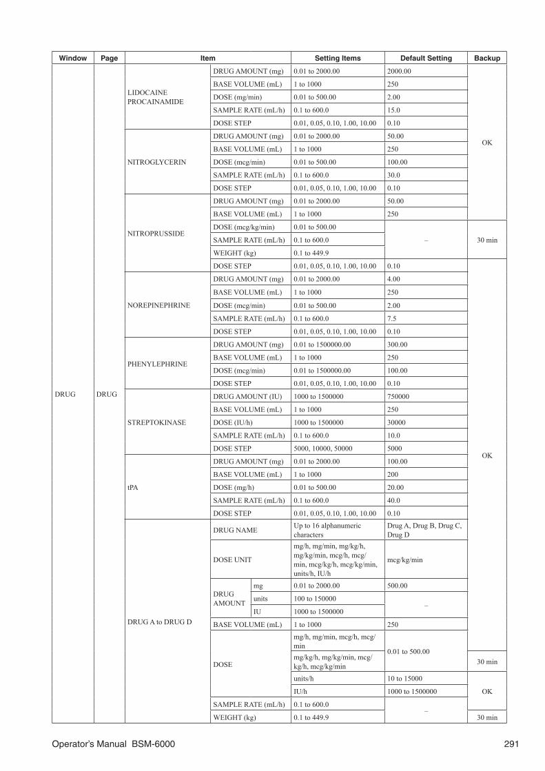
Operator’s Manual BSM-6000 291
Window Page Item Setting Items Default Setting Backup
DRUG DRUG
LIDOCAINEPROCAINAMIDE
DRUG AMOUNT (mg) 0.01 to 2000.00 2000.00
OK
BASE VOLUME (mL) 1 to 1000 250
DOSE (mg/min) 0.01 to 500.00 2.00
SAMPLE RATE (mL/h) 0.1 to 600.0 15.0
DOSE STEP 0.01, 0.05, 0.10, 1.00, 10.00 0.10
NITROGLYCERIN
DRUG AMOUNT (mg) 0.01 to 2000.00 50.00
BASE VOLUME (mL) 1 to 1000 250
DOSE (mcg/min) 0.01 to 500.00 100.00
SAMPLE RATE (mL/h) 0.1 to 600.0 30.0
DOSE STEP 0.01, 0.05, 0.10, 1.00, 10.00 0.10
NITROPRUSSIDE
DRUG AMOUNT (mg) 0.01 to 2000.00 50.00
BASE VOLUME (mL) 1 to 1000 250
DOSE (mcg/kg/min) 0.01 to 500.00
– 30 minSAMPLE RATE (mL/h) 0.1 to 600.0
WEIGHT (kg) 0.1 to 449.9
DOSE STEP 0.01, 0.05, 0.10, 1.00, 10.00 0.10
OK
NOREPINEPHRINE
DRUG AMOUNT (mg) 0.01 to 2000.00 4.00
BASE VOLUME (mL) 1 to 1000 250
DOSE (mcg/min) 0.01 to 500.00 2.00
SAMPLE RATE (mL/h) 0.1 to 600.0 7.5
DOSE STEP 0.01, 0.05, 0.10, 1.00, 10.00 0.10
PHENYLEPHRINE
DRUG AMOUNT (mg) 0.01 to 1500000.00 300.00
BASE VOLUME (mL) 1 to 1000 250
DOSE (mcg/min) 0.01 to 1500000.00 100.00
DOSE STEP 0.01, 0.05, 0.10, 1.00, 10.00 0.10
STREPTOKINASE
DRUG AMOUNT (IU) 1000 to 1500000 750000
BASE VOLUME (mL) 1 to 1000 250
DOSE (IU/h) 1000 to 1500000 30000
SAMPLE RATE (mL/h) 0.1 to 600.0 10.0
DOSE STEP 5000, 10000, 50000 5000
tPA
DRUG AMOUNT (mg) 0.01 to 2000.00 100.00
BASE VOLUME (mL) 1 to 1000 200
DOSE (mg/h) 0.01 to 500.00 20.00
SAMPLE RATE (mL/h) 0.1 to 600.0 40.0
DOSE STEP 0.01, 0.05, 0.10, 1.00, 10.00 0.10
DRUG A to DRUG D
DRUG NAME Up to 16 alphanumeric characters
Drug A, Drug B, Drug C, Drug D
DOSE UNIT
mg/h, mg/min, mg/kg/h, mg/kg/min, mcg/h, mcg/min, mcg/kg/h, mcg/kg/min, units/h, IU/h
mcg/kg/min
DRUG AMOUNT
mg 0.01 to 2000.00 500.00
units 100 to 150000–
IU 1000 to 1500000
BASE VOLUME (mL) 1 to 1000 250
DOSE
mg/h, mg/min, mcg/h, mcg/min
0.01 to 500.00mg/kg/h, mg/kg/min, mcg/kg/h, mcg/kg/min 30 min
units/h 10 to 15000
OKIU/h 1000 to 1500000
SAMPLE RATE (mL/h) 0.1 to 600.0–
WEIGHT (kg) 0.1 to 449.9 30 min

292 Operator’s Manual BSM-6000
Window Page Item Setting Items Default Setting Backup
DRUG DRUG DRUG A to DRUG D DOSE STEP0.01, 0.05, 0.10, 1.00, 10.00, 10, 50, 100, 500, 5000, 10000, 50000
0.10 OK
LUNG FUNCTION Window
Window Page Item Setting Items Default Setting Backup
LUN
G F
UN
CTI
ON
DATA ENTRY
HEIGHT 0.1 to 299.9 cm/inch
– –
WEIGHT 0.1 to 499.9 kg/pound
CO 1 to 20.0 L/min
O2 1 to 100%
ATM 235 to 795 mmHg/kPa
PaCO2 0 to 200 mmHg/kPa
Hb 0.1 to 50.0 g/dL/mmol/L
PaO2 0 to 800 mmHg/kPa
SaO2 1 to 100%
Pv-O2 1 to 100 mmHg/kPa
Sv-O2 0 to 99%
INTERBED Window
Window Page Item Setting Items Default Setting Backup
INTE
RB
ED
SETTINGS AUTO INTERBED DISPLAY ON, OFF OFF
OKSELECT BED
SELECTED BEDS Select from up to 20 beds NONE
GROUP
General, CCU, CCU-1, CCU-2, ER, ICU, ICU-1, ICU-2, OR, Post CCU, Recovery, Tele-1 to Tele-5
General
CAR SEAT CHALLENGE Window
Window Page Item Setting Items Default Setting Backup
CA
R S
EAT
CH
ALL
ENG
E
TEST TEST DURATION 10 min to 24 hour 90 min 30 min
RES
ULT
S
REP
ORT
SET
TIN
GS REPORT ITEMS
TABULAR TREND ON, OFF ON
OK
TREND GRAPH ON, OFF ON
FULL DISCLOSURE ON, OFF ON
TREND INTERVAL 1 min, 5 min, 10 min, 15 min, 30 min, 1h 1 min
TEST PERFORMED BY Up to 16 characters –
30 minCOMMENTS Up to 256 characters –
TEST RESULT PASS, FAIL –

Operator’s Manual BSM-6000 293
Standard Accessories
MU-631RA/MU-651RA/MU-671RA Main Unit
Name Qty Code No. Supply Code
Power cord UL 1 094577 –Operator’s Manual 1 0614-900685U –BSM-6000 series Manuals CD-ROM 1 0644-900031T –
MU-631RK/MU-651RK/MU-671RK Main Unit
Name Qty Code No. Supply Code
Operator’s Manual 1 0614-900685U –BSM-6000 series Manuals CD-ROM 1 0644-900031T –
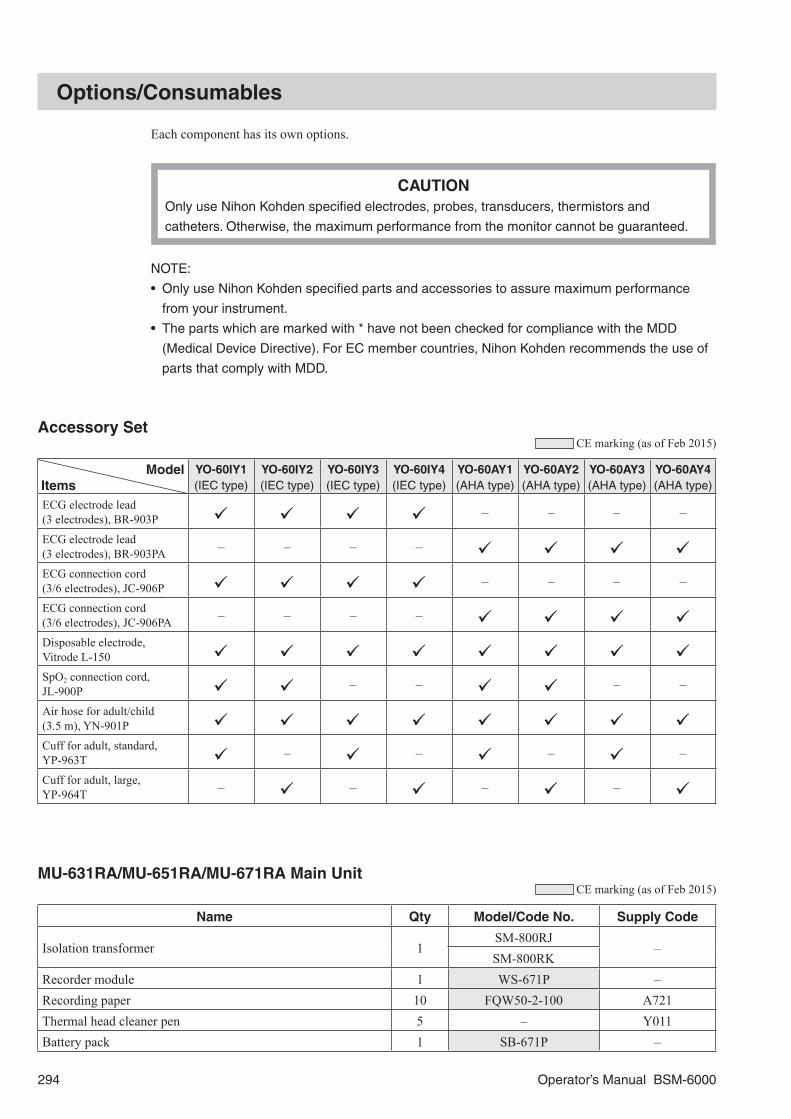
294 Operator’s Manual BSM-6000
Options/Consumables
Each component has its own options.
CAUTIONOnly use Nihon Kohden specified electrodes, probes, transducers, thermistors and
catheters. Otherwise, the maximum performance from the monitor cannot be guaranteed.
NOTE:
• Only use Nihon Kohden specified parts and accessories to assure maximum performance
from your instrument.
• The parts which are marked with * have not been checked for compliance with the MDD
(Medical Device Directive). For EC member countries, Nihon Kohden recommends the use of
parts that comply with MDD.
Accessory Set CE marking (as of Feb 2015)
ModelItems
YO-60IY1(IEC type)
YO-60IY2(IEC type)
YO-60IY3(IEC type)
YO-60IY4(IEC type)
YO-60AY1(AHA type)
YO-60AY2(AHA type)
YO-60AY3(AHA type)
YO-60AY4(AHA type)
ECG electrode lead (3 electrodes), BR-903P – – – –
ECG electrode lead (3 electrodes), BR-903PA – – – –
ECG connection cord(3/6 electrodes), JC-906P – – – –
ECG connection cord(3/6 electrodes), JC-906PA – – – –
Disposable electrode, Vitrode L-150
SpO2 connection cord,JL-900P – – – –
Air hose for adult/child(3.5 m), YN-901P
Cuff for adult, standard, YP-963T – – – –
Cuff for adult, large, YP-964T – – – –
MU-631RA/MU-651RA/MU-671RA Main Unit CE marking (as of Feb 2015)
Name Qty Model/Code No. Supply Code
Isolation transformer 1SM-800RJ
–SM-800RK
Recorder module 1 WS-671P –Recording paper 10 FQW50-2-100 A721Thermal head cleaner pen 5 – Y011Battery pack 1 SB-671P –
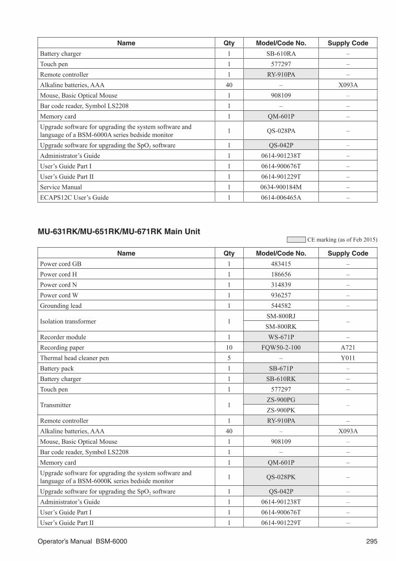
Operator’s Manual BSM-6000 295
Name Qty Model/Code No. Supply Code
Battery charger 1 SB-610RA –Touch pen 1 577297 –Remote controller 1 RY-910PA –Alkaline batteries, AAA 40 – X093AMouse, Basic Optical Mouse 1 908109 –Bar code reader, Symbol LS2208 1 – –Memory card 1 QM-601P –Upgrade software for upgrading the system software and language of a BSM-6000A series bedside monitor 1 QS-028PA –
Upgrade software for upgrading the SpO2 software 1 QS-042P –Administrator’s Guide 1 0614-901238T –User’s Guide Part I 1 0614-900676T –User’s Guide Part II 1 0614-901229T –Service Manual 1 0634-900184M –ECAPS12C User’s Guide 1 0614-006465A –
MU-631RK/MU-651RK/MU-671RK Main Unit CE marking (as of Feb 2015)
Name Qty Model/Code No. Supply Code
Power cord GB 1 483415 –Power cord H 1 186656 –Power cord N 1 314839 –Power cord W 1 936257 –Grounding lead 1 544582 –
Isolation transformer 1SM-800RJ
–SM-800RK
Recorder module 1 WS-671P –Recording paper 10 FQW50-2-100 A721Thermal head cleaner pen 5 – Y011Battery pack 1 SB-671P –Battery charger 1 SB-610RK –Touch pen 1 577297 –
Transmitter 1ZS-900PG
–ZS-900PK
Remote controller 1 RY-910PA –Alkaline batteries, AAA 40 – X093AMouse, Basic Optical Mouse 1 908109 –Bar code reader, Symbol LS2208 1 – –Memory card 1 QM-601P –Upgrade software for upgrading the system software and language of a BSM-6000K series bedside monitor 1 QS-028PK –
Upgrade software for upgrading the SpO2 software 1 QS-042P –Administrator’s Guide 1 0614-901238T –User’s Guide Part I 1 0614-900676T –User’s Guide Part II 1 0614-901229T –
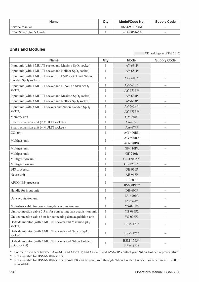
296 Operator’s Manual BSM-6000
Name Qty Model/Code No. Supply Code
Service Manual 1 0634-900184M –ECAPS12C User’s Guide 1 0614-006465A –
Units and Modules CE marking (as of Feb 2015)
Name Qty Model Supply Code
Input unit (with 1 MULTI socket and Masimo SpO2 socket) 1 AY-631P –Input unit (with 1 MULTI socket and Nellcor SpO2 socket) 1 AY-651P –Input unit (with 1 MULTI socket, 1 TEMP socket and Nihon Kohden SpO2 socket) 1 AY-660P*3 –
Input unit (with 1 MULTI socket and Nihon Kohden SpO2 socket)
1 AY-661P*2 –1 AY-671P*2 –
Input unit (with 3 MULTI socket and Masimo SpO2 socket) 1 AY-633P –Input unit (with 3 MULTI socket and Nellcor SpO2 socket) 1 AY-653P –
Input unit (with 3 MULTI sockets and Nihon Kohden SpO2 socket)
1 AY-663P*2 –1 AY-673P*2 –
Memory unit 1 QM-600P –Smart expansion unit (2 MULTI sockets) 1 AA-672P –Smart expansion unit (4 MULTI sockets) 1 AA-674P –CO2 unit 1 AG-400RK –
Multigas unit 1AG-920RA
–AG-920RK
Multigas unit 1 GF-110PA –Multigas unit 1 GF-210R –Multigas/flow unit 1 GF-120PA*3 –Multigas/flow unit 1 GF-220R*3 –BIS processor 1 QE-910P –Neuro unit 1 AE-918P –
APCO/IBP processor 1JP-600P
–JP-600PK*4
Handle for input unit 1 DH-600P –
Data acquisition unit 1JA-690PA
–JA-694PA
Multi-link cable for connecting data acquisition unit 1 YS-096P5 –Unit connection cable 2.5 m for connecting data acquisition unit 1 YS-096P2 –Unit connection cable 5 m for connecting data acquisition unit 1 YS-096P3 –Bedside monitor (with 3 MULTI sockets and Masimo SpO2 socket) 1 BSM-1733 –
Bedside monitor (with 3 MULTI sockets and Nellcor SpO2 socket) 1 BSM-1753 –
Bedside monitor (with 3 MULTI sockets and Nihon Kohden SpO2 socket) 1
BSM-1763*3
–BSM-1773
*2 For the differences between AY-661P and AY-671P, and AY-663P and AY-673P, contact your Nihon Kohden representative.*3 Not available for BSM-6000A series.*4 Not available for BSM-6000A series. JP-600PK can be purchased through Nihon Kohden Europe. For other areas, JP-600P
is available.

Operator’s Manual BSM-6000 297
Network CE marking (as of Feb 2015)
Name Qty Model Supply Code
Hyper isolation transformer 1 HIT-100 –Serial connection cable 1 YS-089P2 –Wireless LAN station 1 QI-320PA –Wireless LAN station 1 QI-420PA –Wireless LAN station 1 QI-610PA –
Interfaces and Cables for External Instruments CE marking (as of Mar 2016)
Name Qty Cable Length (m) Model
Interface for BSM-6301A/K (1 RS-232C socket, 1 RGB socket) 1 – QI-631PInterface for BSM-6301A/K (1 USB socket, 1 Multi-link socket, 1 Alarm socket) 1 – QI-632P
Interface for BSM-6301A/K (1 USB socket, 3 Multi-link sockets) 1 – QI-634P
Interface for TEC-5600 series or TEC-8300 series defibrillator 1 – QI-670P*2
Interface for BSM-6501A/K and BSM-6701A/K (1 Multi-link socket, 1 RS-232C socket, 1 Alarm socket, 1 RGB socket) 1 – QI-671P
Interface for BSM-6501A/K and BSM-6701A/K (2 USB sockets, 4 Multi-link sockets) 1 – QI-672P
Interface unit for data acquisition unit 1 – QI-600PInterface for Covidien Microstream®
Micropod™ capnography module 1 Interface cable: 1.35
Multi-link cable: 0.65 QF-801P
Interface for Dräger Medical ventilator 1 2.7 QF-901PInterface for Covidien BIS™ monitor 1 2.7 QF-902PInterface for Edwards Lifesciences oximeter/continuous cardiac output measuring device 1 2.7 QF-903P
Interface for AG-920RA/K multigas unit 1 2.7 QF-904PInterface for AG-400RK CO2 unit 1 2.7 QF-905P*2
Interface for Covidien Puritan Bennett™ 740, 760 or 840 ventilator 1 2.7 QF-907P
Interface for MAQUET ventilator 1 2.7 QF-908PInterface for Merck & Co./MSD neuromuscular transmission monitor 1 2.7 QF-909P
Interface for Pulsion Medical Systems PiCCO monitor 1 2.7 QF-911PInterface for Oridion Microcap® portable bedside monitor 1 2.7 QF-921P*3
Communication cable for external device which outputs analog voltage signal 1 2.7 IF-912P
Communication cable for Radiometer MicroGas 7650 rapid transcutaneous monitor 1 2.7 IF-913P
Communication cable for Radiometer TCM4, TCM40or TCM CombiM transcutaneous monitor 1 2.7 IF-914P
Communication cable for Newport Medical Instruments ventilator 1 2.7 IF-916P
Communication cable for Hamilton Medical ventilator 1 2.7 IF-917PCommunication cable for Heinen + Löwenstein Leon Plus anesthesia workstation 1 2.7 IF-918P*2

298 Operator’s Manual BSM-6000
Name Qty Cable Length (m) Model
Communication cable for Covidien Nellcor OxiMax™ N-600x™ pulse oximeter 1 2.7 IF-919P
Communication cable for Dräger Medical anesthesia workstation 1 2.7 IF-920P
Communication cable for ICU Medical oxygen saturation and continuous cardiac output monitor 1 2.7 IF-922P
Communication cable for Covidien Puritan Bennett™ 7200 ventilator 1 2.7 IF-923P
Communication cable for Masimo pulse oximeter 1 2.7 IF-925PCommunication cable for CareFusion ventilator 1 2.7 IF-927PCommunication cable for Dräger Medical Babylog® 8000 plus ventilator 1 2.7 IF-928P
Communication cable for GE Healthcare anesthesiadelivery system 1 2.7 IF-930P
Communication cable for Air Liquide Medical Systems Felix Dual, Felix Visio or Felix AlnOC anesthesia system 1 2.7 IF-931P*2
Communication cable for MAQUET FLOW-i anesthesia system 1 2.7 IF-932PCommunication cable for ResMed Elisee 150, 250 or 350 ventilator 1 2.7 IF-933P*2
Communication cable for Air Liquide Medical Systems Monnal T75 ventilator 1 2.7 IF-934P*2
Communication cable for GE Healthcare ventilator 1 2.7 IF-935PCommunication cable for Heinen + Löwenstein Elisa ventilator 1 2.7 IF-936P*2
Communication cable for Covidien INVOS 5100C cerebral/somatic oximeter 1 2.7 IF-937P
Communication cable for Metran ventilator 1 2.7 IF-938PCommunication cable for GE Healthcare Centiva/5 Critical Care ventilator 1 2.7 IF-939P
Communication cable for Dräger Medical Evita Infinity® V500 ventilator 1 2.7 IF-942P
Communication cable for Dräger Medical Babylog® VN500 ventilator 1 2.7 IF-943P
Communication cable for Hamilton Medical HAMILTON-C1 or HAMILTON-T1 ventilator 1 2.7 IF-944P
Communication cable for ACOMA Medical Industry PRO-next+i or PRO-next+s anesthesia apparatus 1 2.7 IF-945P*2
Communication cable for LiDCOrapid or LiDCOplus hemodynamic monitor 1 2.7 IF-946P
Communication cable for Edwards Lifesciencesclinical platform EV1000 1 2.7 IF-948P
Communication cable for Dräger Medical Perseus® A500 anesthesia workstation 1 2.7 IF-950P*2
Communication cable for MAQUET SERVO-U® ventilator and SERVO-n® neonatal ventilator 1 2.7 IF-951P*2
Communication cable for Dräger Medical Zeus® Infinity® Empowered anesthesia workstation 1 2.7 IF-952P*2
*2 Not available for BSM-6000A series.*3 Not available for BSM-6000K series.

Operator’s Manual BSM-6000 299
Cart and Attaching Parts CE marking (as of Feb 2015)
Name Qty Model
Cart 1 KC-600PCounter top mount 1 KG-600PWall mount kit 1 KG-951PHolder for transmitter 1 DI-590PMount adapter for mounting bedside monitor on the GF-210R multigas unit or GF-220R multigas/flow unit 1 DH-220P
Unit mount for mounting GF-210R multigas unit or GF-220R multigas/flow unit on the KC-600P cart 1 DH-223P
For ECG and Respiration (Impedance Method) Monitoring CE marking (as of Feb 2015)
Name Purpose Length (m) Qty Model Supply Code
Electrode lead3 electrodes
IEC, clip type
0.8
1
BR-903P K911BR-963P K916
AHA, clip type BR-903PA K911A
6 electrodesIEC, clip type BR-906P K912AHA, clip type BR-906PA K912A
ECG connection cord
3/6 electrodes (IEC)3
JC-906P K9223/6 electrodes (AHA) JC-906PA K922A3/6 electrodes (IEC) 1.5 JC-916P K92510 electrodes (IEC)
3JC-900P K921
10 electrodes (AHA) JC-900PA K921A
ECG patient cable10 electrodes (IEC)
3.8BJ-900P K901
10 electrodes (AHA) BJ-900PA K901A
ECG/BP output cable
Connects to other equipment for signal output (5 m)
– 1
YJ-910P K974
Connects to other equipment for signal output (0.3 m, horn jack type)
YJ-920P K975
Disposable electrodes, Vitrode
General–
3 × 50 F-150M G210D3 × 20 G-600 G22130 × 5 L-150 G203
General, X-ray 30 × 5 L-150X G207
General with DIN type lead
1.03 × 30
V-090M3 G272A1.5 V-09IO3 G278A1.0
4 × 10V-040M4 G272B
1.5 V-04IO4 G273A1.0
6 × 10V-060M6 G272C
1.5 V-06IO6 G274AFor neonates and premature infantsFor NICU – 3 × 50 F-150S G210C
For neonates and premature infantsFor NICU with DIN type lead 0.6
3 × 40 V-120S3 G271A3 × 10 N-03IS3 G300A
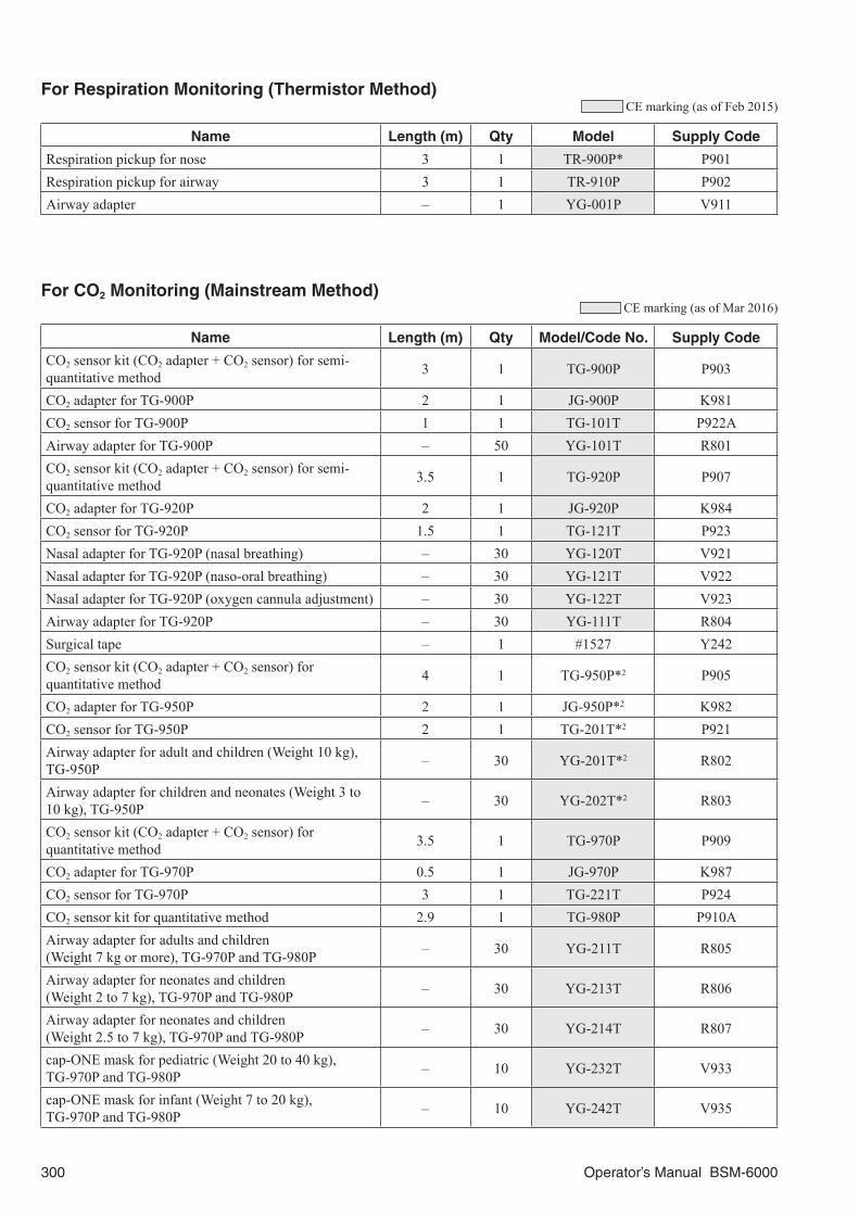
300 Operator’s Manual BSM-6000
For Respiration Monitoring (Thermistor Method) CE marking (as of Feb 2015)
Name Length (m) Qty Model Supply Code
Respiration pickup for nose 3 1 TR-900P* P901Respiration pickup for airway 3 1 TR-910P P902Airway adapter – 1 YG-001P V911
For CO2 Monitoring (Mainstream Method) CE marking (as of Mar 2016)
Name Length (m) Qty Model/Code No. Supply Code
CO2 sensor kit (CO2 adapter + CO2 sensor) for semi-quantitative method 3 1 TG-900P P903
CO2 adapter for TG-900P 2 1 JG-900P K981CO2 sensor for TG-900P 1 1 TG-101T P922AAirway adapter for TG-900P – 50 YG-101T R801CO2 sensor kit (CO2 adapter + CO2 sensor) for semi-quantitative method 3.5 1 TG-920P P907
CO2 adapter for TG-920P 2 1 JG-920P K984CO2 sensor for TG-920P 1.5 1 TG-121T P923Nasal adapter for TG-920P (nasal breathing) – 30 YG-120T V921Nasal adapter for TG-920P (naso-oral breathing) – 30 YG-121T V922Nasal adapter for TG-920P (oxygen cannula adjustment) – 30 YG-122T V923Airway adapter for TG-920P – 30 YG-111T R804Surgical tape – 1 #1527 Y242CO2 sensor kit (CO2 adapter + CO2 sensor) for quantitative method 4 1 TG-950P*2 P905
CO2 adapter for TG-950P 2 1 JG-950P*2 K982CO2 sensor for TG-950P 2 1 TG-201T*2 P921Airway adapter for adult and children (Weight 10 kg), TG-950P – 30 YG-201T*2 R802
Airway adapter for children and neonates (Weight 3 to 10 kg), TG-950P – 30 YG-202T*2 R803
CO2 sensor kit (CO2 adapter + CO2 sensor) for quantitative method 3.5 1 TG-970P P909
CO2 adapter for TG-970P 0.5 1 JG-970P K987CO2 sensor for TG-970P 3 1 TG-221T P924CO2 sensor kit for quantitative method 2.9 1 TG-980P P910AAirway adapter for adults and children (Weight 7 kg or more), TG-970P and TG-980P – 30 YG-211T R805
Airway adapter for neonates and children(Weight 2 to 7 kg), TG-970P and TG-980P – 30 YG-213T R806
Airway adapter for neonates and children(Weight 2.5 to 7 kg), TG-970P and TG-980P – 30 YG-214T R807
cap-ONE mask for pediatric (Weight 20 to 40 kg), TG-970P and TG-980P – 10 YG-232T V933
cap-ONE mask for infant (Weight 7 to 20 kg), TG-970P and TG-980P – 10 YG-242T V935

Operator’s Manual BSM-6000 301
Name Length (m) Qty Model/Code No. Supply Code
cap-ONE mask for adult (Weight 30 or more), TG-970P and TG-980P – 10 YG-272T V938A
cap-ONE mask for adult (Weight 40 or more), large, TG-970P and TG-980P – 10 YG-282T V938C
*2 Not available for BSM-6000A series.
For SpO2 Monitoring CE marking (as of Feb 2015)
Name Length (m) Qty Model/Code No. Supply Code
SpO2 connection cord (for Masimo SpO2 probe)
for LNOP series probe 3.6 1 JL-630P –
for LNCS series probe 3.0 1 JL-631P –
SpO2 connection cord (for Nellcor SpO2 probe) 3.0 1 JL-650P –SpO2 connection cord (for Nihon Kohden SpO2 probe) 2.5 1 JL-900P K931
SpO2 adapter 2.51 JL-500P1*2 –1 JL-500P2*2 –
Finger probe 1.6 1 TL-201T P225FMulti-site probe 1.6 1 TL-220T P225GFinger probe (for 50 kg or more, adults or children) 1.6 1 TL-630T3*3 P310CFinger probe (for 20 kg or more, adults or children) 1.6 1 TL-631T3 P311CMulti-site Y probe (for adults, children and neonates, disposable) 1.6 5 TL-260T*3 P205A
SpO2 probe (for adult, disposable)0.8 24 TL-271T P203A1.6 24 TL-271T3 P203E
SpO2 probe (for child, disposable)0.8 24 TL-272T P203B1.6 24 TL-272T3 P203F
SpO2 probe (for neonate/adult, disposable)0.8 24 TL-273T P203C1.6 24 TL-273T3 P203G
SpO2 probe (for child/infant, disposable)0.8 24 TL-274T P203D1.6 24 TL-274T3 P203H
Disposable probe (for adults and neonates)0.8 5 TL-051S P228A1.6 5 TL-052S P228B
Disposable probe (for adults, children and infants)0.8 5 TL-061S P229A1.6 5 TL-062S P229B
Probe fastener – 30 YS-093P2 P267Attachment tape – 3 × 30 – P263Sponge attachment tape S for TL-260T multi-site Y probe*3 – 24 – P260A
Sponge attachment tape L for TL-260T multi-site Y probe*3 – 24 – P260B
Clip adapter for TL-260T multi-site Y probe*3 – 1 – P256Foam tape for TL-051S/052S/061S/062S disposable probes – 4 × 25 – P260
SpO2 check plate for TL-201T finger probe – 1 6114-121095 –
*2 For the differences between JL-500P1 and JL-500P2, contact your Nihon Kohden representative.*3 Not available for BSM-6000A series.

302 Operator’s Manual BSM-6000
For NIBP Monitoring CE marking (as of Feb 2015)
Name Width (cm) Length (m) Qty Model/Code No. Supply Code
Air hose for adults/children–
1.5 1 YN-900P S9013.5 1 YN-901P S902
Extension air hose 1.5 1 YN-990P S903
Cuff for infants 50.15 1 YP-960T S943A0.15 1 YP-710T S951A
Cuff for childrenSmall 7
0.15 1 YP-961T S943B0.15 1 YP-711T S951B
Standard 100.15 1 YP-702T S949A0.15 1 YP-962T S943C
Cuff for adult
Small 10 0.15 1 YP-712T*2 S951C
Standard 130.15 1 YP-703T S949B0.15 1 YP-713T*2 S951D0.15 1 YP-963T S944B
Large15 0.15 1 YP-964T S944C16 0.15 1 YP-714T*2 S951E
Cuff for thigh 190.15 1 YP-715T*2 S951F0.15 1 YP-965T S944D
Disposable cuff for infants 6 0.17 20 YP-810P S945CDisposable cuff for children 8 0.17 20 YP-811P S945D
Disposable cuff for adults
Small 10 0.17 20 YP-812P S946EStandard 14 0.17 20 YP-813P S946FMedium large 15 0.17 20 YP-814P S946GLarge 17 0.17 20 YP-815P S946HExtra large 18 0.17 20 YP-816P S946I
Disposable cuff for thigh 20 0.17 20 YP-817P S946J
Air hose for neonates– 1.5 1 YN-920P S904– 3.5 1 YN-921P S905
Disposable cuff for neonates
2 0.2 10 YP-820P S948A3 0.2 10 YP-821P S948B4 0.2 10 YP-822P S948C
4.5 0.2 10 YP-823P S948D5 0.2 10 YP-824P S948E
*2 Can be used for inflation method measurement when an Inflate Mode (iNIBP) compatible input unit is mounted on a BSM-6000K series bedside monitor.

Operator’s Manual BSM-6000 303
For IBP MonitoringArgon Medical Devices Reusable Transducers
CE marking (as of Feb 2015)
Name Length, Description Qty Model Supply Code
IBP connection cord For P23XL-1, P10EZ-1 and Argon Medical Devices transducers, 3.5 m 1 JP-900P K951
IBP connection cord For Argon Medical Devices transducers,0.3 m 1 JP-910P K952
IBP transducer – 1 P23XL-1 –IBP transducer – 1 P10EZ-1 –Monitoring kit For P23XL-1 5 SCK-520* S571Super dome – 10 TA-1015T –Dome With membrane, rotatory lure lock 12 TA-1010ND –Criti flo 3 cc 10 TA-4004 –Criti flo 30 cc 10 TA-4005* –Transducer holder – 1 ZY-101U* S238Transducer holder For P23XL-1 1 TA-9010* –Adapter 2 For P23XL-1, used with ZY-101U 1 – S239Pressure tubing 15 cm 25 PT-06 –Pressure tubing 30 cm 25 PT-12 –Pressure tubing 60 cm 25 PT-24 –Pressure tubing 90 cm 25 PT-36 –Pressure tubing 120 cm 25 PT-48 –Pressure tubing 150 cm 25 PT-60 –
Argon Medical Devices Disposable Transducers CE marking (as of Feb 2015)
Name Length, Description Qty Model Supply Code
IBP connection cord 3.5 m 1 JP-900P K951IBP connection box 2.7 m, for 4 channels 1 JP-940P –Monitoring kit For cerebral pressure 10 DX-100* –Monitoring kit For neonates 10 DX-200* –Monitoring kit With flush device 10 DX-300* –Monitoring kit For arm mounting 5 DX-312* –Monitoring kit For pole mounting 5 DX-360* –Monitoring kit For pole mounting 5 DX-360R* –Monitoring kit For triple line 3 DX-360TT* –Monitoring kit For pole mounting 5 DX-360SD* –Transducer fixing plate – 1 G-TBG2 –Transducer fixing plate – 1 G-TMM –Transducer fixing plate – 1 G-UMM –Safe needle For DX-360SD 50 TA-BPN* –

304 Operator’s Manual BSM-6000
Edwards Lifesciences (Baxter) Disposable Transducers
Edwards Lifesciences (Baxter) blood pressure transducers are available direct from Edwards Lifesciences (Baxter) (www.edwards.com) or their suppliers.
CE marking (as of Feb 2015)
Name Length, Description Qty Model Supply Code
IBP connection cord For Edwards Lifesciences (Baxter) transducers, 3.5 m 1 JP-920P L901
Other CE marking (as of Feb 2015)
Name Length, Description Qty Model/Code No. Supply Code
IBP connection cord For Biosensor, 3.5 m 1 JP-960P K957
IBP connection cordFor Integra NeuroSciences Camino® MPM-1 multi-parametermonitor
1 JP-911P –
ECG/BP output cable
Connects to other equipment for signal output (5 m) 1 YJ-910P K974
Connects to other equipment for signal output (0.3 m, horn jack type) 1 YJ-920P K975
Pressure bag – 1 ACS-223* S160ADisposable 3-way stopcock – 50 318434* S1803-way stopcock 3 core 1 MF-3F* S3143-way stopcock 5 core 1 MF-5F* S315Holder For 5 core stopcock 1 – S226
For Temperature Monitoring CE marking (as of Feb 2015)
Name Purpose Length (m) Qty Model/Code No. Supply Code
Temperature connection cord
For reusable probe/disposable probe 0.3 1 JT-900P K961
Reusable thermistor probeFor adult rectum 3.5 1 401J*2 P240AFor child rectum 3.5 1 402J*2 P241ADisc type 3.5 1 409J*2 P242D
Probe cover For 401J – 10 – P249ATemperature insulation pad For 409J – 5 dozens 336468 P252
Extension cable For disposable probes 3 1 5-15801 L280A
*2 These thermistor probes are available direct from YSI, Yellow Springs Instrument Inc., Yellow Springs Ohio 45387, USA; Phone +1 937-767-7241.
The temperature disposable probes are available direct from Kendall Healthcare Products Company (www.kendallhq.com) or their suppliers.

Operator’s Manual BSM-6000 305
For BIS Monitoring (Using the BIS Processor/BISx)Covidien patient interface cable and BIS sensors are available direct from Covidien (www.covidien.com) or their suppliers.
CE marking (as of Feb 2015)
Name Length, Description Qty Model Supply Code
BISx connection cable 0.3 m 1 YJ-671P –
For CO Monitoring CE marking (as of Feb 2015)
NameMeasuring Method
and CatheterLength (m) Qty Model Supply Code
CO connection cord Bath probe and inline sensor methods 2.0 1 JT-950P K962
Bath probe Any catheter, bath probe method 1.5 1 SP-5030 –
Inline sensorArgon Medical Devices catheter inline sensor method
– 25 SP-5045 –Inline sensor connection cable – 1 SP-4045 –
Inline iced injectate kit – 4 SP-4500 –
Life kit Bath probe and inline sensor methods – 5 DX-336DT* –
Argon Medical Devices Thermodilution Catheters
Model Specifications Thickness (F) Lumen Total length (m) Qty Supply Code
TC-664MP* Made of polyurethane 6 4 1.1 1 –TC-704MU* Soft type 7 4 1.1 1 –TC-774MP* Made of polyurethane 7 4 1.1 1 –
Edwards Lifesciences (Baxter) Catheters
Edwards Lifesciences (Baxter) catheters are available direct from Edwards Lifesciences (Baxter) (www.edwards.com) or their suppliers.
For O2 Monitoring CE marking (as of Feb 2015)
Name Length (m) Qty Model/Code No. Supply Code
FiO2 connection cord 3 1 JO-900P K941O2 sensor 0.6 1 074705 P911T shaped adapter – 1 110774 V912
For CCO MonitoringFloTrac system and sensors are available direct from Edwards Lifescience (Baxter) (www.edwards.com) or their suppliers.
For CO2 Sidestream MonitoringRefer to the AG-400R CO2 Unit, Oridion Portable Bedside Monitor Microcap®, or Covidien Microstream® Micropod™ Capnography Module Operator’s Manual.

306 Operator’s Manual BSM-6000
For BIS Monitoring (Using the BIS Monitor)Refer to the BIS Monitor Operator’s Manual.
For Anesthetic Agent MonitoringRefer to the AG-920R, GF-110PA or GF-210R Multigas Unit or GF-120PA or GF-220R Mutigas/Flow Unit Operator’s Manual.
For FLOW/Paw MonitoringRefer to the GF-120PA Multigas/Flow Unit Operator’s Manual.
For EEG MonitoringRefer to the AE-918P Neuro Unit Operator’s Manual.

Operator’s Manual BSM-6000 307
General Requirements for Connecting Medical Electrical Systems
When more than one electrical instrument is used, there may be electrical potential difference between the instruments. Potential difference between instruments may cause current to flow to the patient connected to the instruments, resulting in electrical shock. Therefore, electrical instruments must be appropriately installed as specified in IEC 60601-1-1: 2000.
The following is an extract from IEC 60601-1-1 “Medical electrical equipment Part 1: General requirements for safety”. For details, refer to IEC 60601-1-1 and consult with a biomedical engineer.
Examples of combinations of MEDICAL ELECTRICAL EQUIPMENT and non-medical electrical equipment
Inside the PATIENTENVIRONMENT
Outside thePATIENT
ENVIRONMENT
1a Items A and B inPATIENTENVIRONMENT
1b Items A and B inPATIENTENVIRONMENT
For B: Additionalprotective earth orseparating transformer
1c Item A poweredfrom specified powersupply in item B inPATIENTENVIRONMENT
For B: Additionalprotective earth orseparating transformer
2a Item A inPATIENTENVIRONMENT anditem B in medicallyused room2b Item A inPATIENTENVIRONMENT anditem B in medicallyused room
For B: See 19.201 and itsrationale
3a Item A inPATIENTENVIRONMENT anditem B in non-medicallyused room
For B: See 19.201 and itsrationale
3b Item A inPATIENTENVIRONMENT anditem B in non-medicallyused room
For B: Additionalprotective earth orSEPARATION DEVICE
Medically used room
Non-medically usedroom
Feasible solution (Seeclause 19 in all
situations)
1
2
3
Situation No.
A
IEC60601
B
IEC60601
A
IEC60601
B
IECXXXXX
A
IEC60601
B
IEC60601
A
IEC60601
B
IECXXXXX
A
IEC60601
BIEC 60601
orIEC XXXXX
A
IEC60601
protective earth withpotential difference
protective earth
AIEC 60601
BIEC XXXXX
common protective earth
BIEC 60601
orIEC XXXXX
KEY TO TABLE• Additional protective earth: If necessary, provide additional protective earthing, which is permanently connected (see also
58.201). NOTE: Equipment modification may be required.• Separating transformer: If necessary, limit the ENCLOSURE LEAKAGE CURRENT, by using an additional separating
transformer according to annex EEE. NOTE 1: No equipment modification is required. NOTE 2: A separating transformer is a transformer with one or more input winding(s) separated from the output winding(s)
by at least basic insulation [IEC 60989].• SEPARATION DEVICE: If necessary, apply SEPARATION DEVICE.• IEC 60601: MEDICAL ELECTRICAL EQUIPMENT in compliance with IEC 60601.• IEC XXXXX: Non-medical equipment in compliance with relevant IEC safety standards.

Serial NumberModel
Your Representative
Contact information is accurate as of July 2016. Visit www.nihonkohden.com for the latest information.
The model and serial number of your instrument are identified on the rear or bottom of the unit.Write the model and serial number in the spaces provided below. Whenever you call your representative concerningthis instrument, mention these two pieces of information for quick and accurate service.
Manufacturer
NIHON KOHDEN CORPORATION1-31-4 Nishiochiai, Shinjuku-ku Tokyo 161-8560, JapanPhone +81 3-5996-8036 Fax +81 3-5996-8100
North and South America
NIHON KOHDEN AMERICA, INC.15353 Barranca Parkway, Irvine, CA 92618, U.S.A.Toll-free +1-800-325-0283 Phone +1 949-580-1555 Fax +1 949-580-1550
NIHON KOHDEN MEXICO S.A. DE C.V. Insurgentes Sur 730, Piso 9 Oriente, Col. Del ValleC.P. 03100, Delegacion Benito Juarez, Mexico, D.F. Phone +52 55-8851-5550 Fax +52 55-8851-5580
NIHON KOHDEN DO BRASIL LTDA. Rua Diadema, 89, 1º andar, conjuntos 11 a 17, bairro Mauá no Município de São Caetano do Sul, Estado de São Paulo CEP 09580-670, BrasilPhone +55 11-3044-1700 Fax +55 11-3044-0463
Europe European Representative
NIHON KOHDEN EUROPE GmbHRaiffeisenstrasse 10, D-61191 Rosbach, GermanyPhone +49 6003-827-0 Fax +49 6003-827-599
NIHON KOHDEN DEUTSCHLAND GmbHRaiffeisenstrasse 10, D-61191 Rosbach, GermanyPhone +49 6003-827-0 Fax +49 6003-827-599
NIHON KOHDEN FRANCE SARL8, rue Francois Delage, 94 230 Cachan, FrancePhone +33 1-49-08-05-50 Fax +33 1-49-08-93-32
NIHON KOHDEN IBERICA S.L.C/Ulises 75A, E-28043 Madrid, SpainPhone +34 917-161-080 Fax +34 913-004-676
NIHON KOHDEN ITALIA S.r.l.Via Fratelli Bronzetti 28, 24124 Bergamo, Italy Phone +39 035-219543 Fax +39 035-232546
NIHON KOHDEN UK LTD.Trident Court 118, 1 Oakcroft RoadChessington, Surrey KT9 1BD, UKPhone +44 20-8391-6800 Fax +44 20-8391-6809
Asia
SHANGHAI KOHDEN MEDICAL ELECTRONIC INSTRUMENT CORP. 567 Huancheng Bei RoadShanghai Comprehensive Industrial Development ZoneShanghai 201401, ChinaPhone +86 21-5743-6998Fax +86 21-5743-6939 NIHON KOHDEN SINGAPORE PTE LTD1 Maritime Square, #10-34 HarbourFront CentreSingapore 099253Phone +65 6376-2210 Fax +65 6376-2264
NIHON KOHDEN INDIA PVT. LTD. 308, Tower A, Spazedge, Sector 47, Sohna RoadGurgaon-122 002 Haryana, IndiaToll-free +91 1800-103-8182 Phone +91 124-493-1000 Fax +91 124-493-1029
NIHON KOHDEN MIDDLE EAST FZE JAFZA One Tower A, 19th floor, Office No. 1912Jebel Ali Free Zone, P.O. Box 261516, Dubai, U.A.E.Phone +971 4-884-0080 Fax +971 4-880-0122
NIHON KOHDEN KOREA, INC.5F Miso Bldg.890-47 Daechi-dong, Gangnam-gu, Seoul, 135-280 KoreaPhone +82 2-3273-2310 Fax +82 2-3273-2352