
MODEL 210 - Best Equipment Company
42
MODEL 210 TYMCO P.O. BOX 2368, WACO, TEXAS 76703 (Shipping Address) 225 INDUSTRIAL EAST WACO, TEXAS 76705 PHONE: 254-799-5546 • FAX: 254-799-2722 WEB SITE: www.tymco.com E-MAIL ADDRESS: [email protected] OPERATOR'S MANUAL 2008
-
Upload
khangminh22 -
Category
Documents
-
view
1 -
download
0
Transcript of MODEL 210 - Best Equipment Company

MODEL210
TYMCOP.O. BOX 2368, WACO, TEXAS 76703
(Shipping Address)225 INDUSTRIAL EAST WACO, TEXAS 76705PHONE: 254-799-5546 • FAX: 254-799-2722
WEB SITE: www.tymco.comE-MAIL ADDRESS: [email protected]
OPERATOR'SMANUAL
2008


CONGRATULATIONS
You have just purchased the finest air sweeper produced. Yet, for all of its advanced engineer-ing, in spite of all the skills that have gone into it - your sweeper is only as good as its operator.
TYMCO REGENERATIVE AIR SWEEPER SOLD & SERVICED BY:MODEL 210
NOTE: DO NOT destroy any part of this manual. It contains pertinent information onparts, operation and maintenance of your TYMCO REGENERATIVE AIRSWEEPER and truck chassis.
An informed operator will do a better job. Make sure he/she has anopportunity to study this manual.
This Operator’s Manual is the property of TYMCO, and is considered proprietary.It may not be reproduced by photocopying or otherwise without
the express written permission of TYMCO.Violators will be prosecuted to the full extent of the law.
© 1995 TYMCO2008 EDITION


INTRODUCTION
To insure proper understanding of operation, cleaning and maintenance of your TYMCO RE-GENERATIVE AIR SWEEPER, it is necessary that this Operator’s Manual and the Service &Parts Manual be read and studied from cover to cover by the operator. A full understanding ofthis equipment will help the operator achieve the results expected of this machine.
Though, seemingly, a very simple machine, the TYMCO REGENERATIVE AIR SWEEPERutilizes air instead of conventional rotary brushes, brooms and conveyers. Aerodynamic prob-lems that arise in the REGENERATIVE AIR SWEEPER are not as easily identified and, there-fore, necessitates a complete understanding of the machine.
The TYMCO REGENERATIVE AIR SWEEPER is designed to maintain cleaner surfaces athigher speeds and at lower cost. The performance capability of this truly modern machine isonly limited by the initiative of those responsible for its operation. There are many different con-ditions found in sweeping, and we believe it impossible to answer all of the problems here.Most important in the operation and maintenance of this machine, is that it should be KEPTCLEAN.
The Operator’s Manual includes the necessary checks, operating and adjustment proceduresneeded by the operator from day to day. For any specific adjustment, problem, or maintenancechecks not explained in this manual, please refer to the Service & Parts Manual.
CLEAN OUR STREETS AND PARKING AREASPICK IT UP WITH YOUR TYMCO


TIL-053 / September 9, 2004
Operating Procedure GuidelinesComplete Sweeper Inspection
• Check Auxiliary Engine Oil and Coolant• Check for Seal leaks• Check Warning and Work Lights• Inspect Pick-Up Head• Check Gutter Broom• Adjust Mirrors• Fill Fuel Tank• Fill Water System
Sweeper Start-Up Procedures1. Start Rear Engine (Must be in idle)2. Turn on Warning Lights3. Turn on Water System4. Lower Pick-Up Head5. Pull Sweeper forward to tuck Pick-Up Head Curtains6. Throttle up Auxiliary Engine RPM to desired levels7. Lower Gutter Broom(s)8. Begin sweeping9. DO NOT BACK UP WITH PICK-UP HEAD DOWN. Throttle down, raise head then back up.
(Optional Reverse Pick-Up Head Chains allow you to back up with the head down.)
CNG Option Start-Up1. Slowly open fuel service valve on each CNG fuel tank, if not already open.2. Slowly open fuel shutoff valves 1/4 turn.3. Start engine and idle for five minutes to allow time for warm-up before engaging transmission.4. Start auxiliary engine and idle for five minutes to allow time for warm-up before raising RPM.
NOTE: This procedure supplements the sweeper Start-Up Procedure above. Read and comply with both.
Leaf Pressure Bleeder Procedures• Closed for heavy debris such as Sand, Gravel, Dirt; Etc. (Use BAH when necessary)• Open 100% when sweeping light debris such as Leaves, Paper Cups, Etc.• Adjust opening 25% to 75% for mixed debris
Sweeper Shutdown Procedures1. Lower Auxiliary Engine RPM to idle speed (1000 RPM)2. Raise Gutter Brooms - (Must hold switch in the up position to fully retract gutter broom)3. Raise Pick-Up Head - (Must hold switch to retract to the travel position)4. Turn off Water System5. Turn off Warning Lights6. Turn off Auxiliary Engine
CNG Option Shutdown1. Bring all sweeper components to their stowed position.2. Lower engine RPM to idle on both engines for a minimum of 3 minutes to allow engine to cool down.3. Ignition switches may now be turned off.
NOTE: If sweeper is to be parked in an enclosed area, close both 1/4 turn fuel shutoff valves and allow engines torun until both shut down due to fuel starvation, then close the service valve on each CNG tank.This procedure supplements the sweeper Shutdown Procedure above. Read and comply with both.
Wash Out Procedures (DAILY)• Clean Hopper Screens• Clean out Hopper• Clean out Dust Separator• Clean under Pick-Up Head• Wash exterior of Sweeper and Chassis• Wash off Radiators
Parking Procedures• Raise Hopper and lower on 2x4 Wood Blocks - Do not close rear door (Model 210 - 435)• Leave Hopper Door and Inspection Door(s) open (All Model 600s)

TIL-064 / August 4, 2006
TYMCO REGENERATIVE AIR SWEEPER INSPECTIONAND REPETITIVE TASK SCHEDULE
600 500X 435 210
ADJUSTMENT OF GUTTER BROOM(S) A/R A/R A/R A/R
CLEANING OF GUTTER BROOM D D D DTORQUE MOTOR SHAFT AREA
ROTATE PRESSURE AND SUCTION 75 75 75 75HOSES 1/4 TURN HRS HRS HRS HRS
CHECK OF HYDRAULIC TANK D D D DFLUID LEVEL
CHANGE OF HYDRAULIC 100 100 100 100SYSTEM FILTER HRS HRS HRS HRS
TANK BREATHER FILTER N/A 100 N/A N/AHRS
RETURN LINE FILTER - RESTRICTION N/A 100 N/A N/AINDICATOR HRS
CHARGE LOOP FILTER - RESTRICTION N/A 100 N/A N/AINDICATOR HRS
HYDRAULIC SYSTEM OIL CHANGE 1000 1000 1000 1000NOTE: INITIAL CHANGE AT 100 HRS HRS HRS HRS HRS
CHANGE OF WATER PUMP OIL 150 150 150 150(IF APPLICABLE) HRS HRS HRS HRS
CLEANING OF SPRAY NOZZLE TIPS A/R A/R A/R A/RAND SCREENS
DRAIN WATER TANK D D D D
CLEANING OF HOPPER AND DUST D D D DSEPARATOR CHAMBER
AUXILIARY ENGINE FLUID LEVEL CK. D D D D
WASHDOWN OF ENGINE RADIATOR(S) D D D D
FUNCTIONAL TEST SWEEPER LIGHTS D D D D
FUNCTIONAL TEST OF TRUCK BRAKES D D D D
FUNCTIONAL TEST OF TRUCK LIGHTS D D D D
MOUNT TRUCK FLUID LEVEL CHECK D D D D
PERFORMMODEL
600 500X 435 210
GUTTER BROOM(S) FOR IMPACT D D D DDAMAGE/WEAR
PICK-UP HEAD BLAST ORIFICE FOR D D D DLODGED FOREIGN MAT'L/ADJUSTMENT
PICK-UP HEAD TURNING VANES 100 100 100 100FOR WEAR/FOREIGN MATERIAL HRS HRS HRS HRS
PICK-UP HEAD SKID PLATES FOR D D D DWEAR AND IMPACT DAMAGE
PICK-UP HEAD CURTAINS FOR D D D DWEAR/DAMAGE
PRESSURE AND SUCTION HOSES 100 100 100 100FOR WEAR HRS HRS HRS HRS
HYDRAULIC SYSTEM FOR PLUMB- D D D DING OR COMPONENT LEAKAGE
WATER PUMP OIL LEVEL D D D D(IF APPLICABLE)
WATER FILLER HOSE FILTER D D N/A N/ASCREEN
WATER PUMP SUCTION HOSE D D D DPRE-FILTER
ALL HOPPER AND TRANSITION D D D DSEALS FOR WEAR/DAMAGE
HOPPER SCREEN FOR DAMAGE D D D D
DUST SEPARATOR LINER FOR D D N/A N/AWEAR/DAMAGE
DUST SEPARATOR DOOR CLOSED D D N/A N/ABEFORE OPERATING
BLOWER WHEEL FOR 100 100 100 100WEAR/DAMAGE HRS HRS HRS HRS
ACCESSIBLE AREAS OF BLOWER 100 100 100 100HOUSING LINER FOR WEAR/DAMAGE HRS HRS HRS HRS
BLOWER LIP FOR WEAR/DAMAGE 100 100 100 100HRS HRS HRS HRS
ENGINE AIR INTAKE FILTER D D D DRESTRICTION INDICATORS
MOUNT TRUCK TIRES D D D D
INSPECTMODEL
D = DAILYHRS = HOURLY INTERVALSA/R = AS REQUIRED

TABLE OF CONTENTS
TYMCO REGENERATIVE AIR SYSTEM®. . . . . . . . . . . . . . . . . . . . . . . . . . . . . . . . . . . 1
TYMCO SWEEPER Capabilities. . . . . . . . . . . . . . . . . . . . . . . . . . . . . . . . . . . . . . . . . . . 1
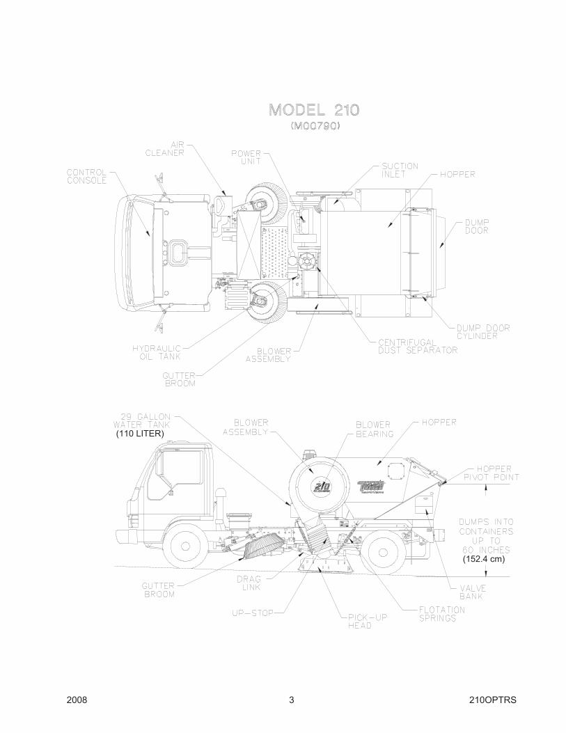
Detailed Drawing. . . . . . . . . . . . . . . . . . . . . . . . . . . . . . . . . . . . . . . . . . . . . . . . . . . . . . . 3
Console Control Panel Drawings . . . . . . . . . . . . . . . . . . . . . . . . . . . . . . . . . . . . . . . . . . 4
Quick Reference Service Chart. . . . . . . . . . . . . . . . . . . . . . . . . . . . . . . . . . . . . . . . . . . . 6
Hopper Assembly . . . . . . . . . . . . . . . . . . . . . . . . . . . . . . . . . . . . . . . . . . . . . . . . . . . . . . 7
Blower Assembly . . . . . . . . . . . . . . . . . . . . . . . . . . . . . . . . . . . . . . . . . . . . . . . . . . . . . . 9
Hydraulic System . . . . . . . . . . . . . . . . . . . . . . . . . . . . . . . . . . . . . . . . . . . . . . . . . . . . . 14
Gutter Broom . . . . . . . . . . . . . . . . . . . . . . . . . . . . . . . . . . . . . . . . . . . . . . . . . . . . . . . . 16
Pick-Up Head . . . . . . . . . . . . . . . . . . . . . . . . . . . . . . . . . . . . . . . . . . . . . . . . . . . . . . . . 19
Pressure Bleeder . . . . . . . . . . . . . . . . . . . . . . . . . . . . . . . . . . . . . . . . . . . . . . . . . . . . . 24
Dust Control System . . . . . . . . . . . . . . . . . . . . . . . . . . . . . . . . . . . . . . . . . . . . . . . . . . . 25
Winterization . . . . . . . . . . . . . . . . . . . . . . . . . . . . . . . . . . . . . . . . . . . . . . . . . . . . . . . . . 27
Wisconsin Power Unit Starting Procedure . . . . . . . . . . . . . . . . . . . . . . . . . . . . . . . . . . 27
Hand Hose Option . . . . . . . . . . . . . . . . . . . . . . . . . . . . . . . . . . . . . . . . . . . . . . . . . . . . 28
Auto Sweep Interrupt (ASI) (Optional) . . . . . . . . . . . . . . . . . . . . . . . . . . . . . . . . . . . . . 29
Warranty . . . . . . . . . . . . . . . . . . . . . . . . . . . . . . . . . . . . . . . . . . . . . . . . . . . . . . . . . . . . 31

2008 1 210OPTRS
THE TYMCO REGENERATIVE AIR SYSTEM
DESCRIPTION
The blower generates a constant blast of high velocity air that is directed down the pressureside of the machine and into the pick-up head. Blast air travels across the pick-up head, pickingup normal debris and refuse in its path and sending it up the suction side of the machine.
At the same time that the blower is directing pressure down the pressure side, it is taking airfrom inside the hopper, creating a suction; and consequently, it pulls debris up into the hopper.The debris is deposited into the hopper while dusty air passes through the screen to amultipass, centrifugal dust separator. The fines are then deposited back into the hopperthrough the skimmer slot. Air, containing very fine dust, then moves into the blower and repeatsits cycle.
The unique REGENERATIVE AIR SWEEPER uses no restricting filters, resulting in more en-ergy to do your work. Since the blower is used to push and pull, restriction due to clogging ormodification to any of the air passages will greatly affect the sweeper’s performance. In otherwords, PRESSURE FOR THE BLAST depends on ample volume of air through the suction;SUCTION depends on the discharge of air from the blast orifice.
Another point to consider is the fact that a very small air leak at the dump door, inspectiondoors, hand hose door, or suction hose will often cause a dusty condition. If the leak is severeenough, air will have a slower velocity and performance will be lowered.
DO NOT ALLOW EVEN A SMALL AIR LEAKCLEAN FRESH AIR DRAWN IN WILL BE DISCHARGED AS DUST
TYMCO REGENERATIVE AIR SWEEPER CAPABILITIES
We at TYMCO honestly believe that government officials, contractors and all personnel di-rectly responsible for the performance and maintenance of equipment in their charge are con-cerned with all phases of their operation.
Sweepers are one of the most controversial pieces of equipment with reference to operatingcost, performance, and maintenance. The general public does not realize the problems anddepends on people knowledgeable in this area. You, therefore, the person responsible for theperformance and maintenance of the sweeper should use your knowledge and experience toachieve the results expected.
The TYMCO REGENERATIVE AIR SWEEPER can achieve your anticipated results whilekeeping cost at a minimum. However, to realize the full potential of the TYMCO REGENERA-TIVE AIR SWEEPER, YOU MUST UNDERSTAND ITS CAPABILITIES AND ADHERECLOSELY TO OPERATING AND JOB FUNCTIONS FOR WHICH IT WAS DESIGNED.
It is a fact that a licensed driver can operate this equipment; however, we strongly recommendthat the same driver operate it daily. It is proven that ability on the equipment is increased withexperience. We suggest that every operator thoroughly read and study the manual to makesure that he/she understands its operation before ever attempting to operate the sweeper. It isvery important that every new operator be given this opportunity and that he does not relysolely on methods of previous operators.

210OPTRS 2 2008
A TYMCO REGENERATIVE AIR SWEEPER can be expected to clean normal debris that mayaccumulate on streets, parking lots, and other flat paved surfaces. Using the machine for morethan it was originally designed will cause excessive wear and failure to achieve the desiredresults.
This sweeper is not a Vacuum Cleaner. Cleaning is actually done by a stream of high velocityair the full width of the pick-up head. A blower furnishes both pressure and suction. Air pressurefrom the blower passes over the surface being swept within the pick-up head, blows up debris inits path, and the suction pulls it into the hopper, where it is separated. Air continues on into theblower and the cycle is repeated.
The TYMCO REGENERATIVE AIR SWEEPER is not intended nor is it expected to replace ashovel crew or a front end loader. An inspection at the dump site, however, may reveal thatthere are rocks and large objects in the hopper. This is due to air currents in the TYMCO RE-GENERATIVE AIR SYSTEM having the potential to pick up various large objects and retainthem. The mixture of light debris will sometimes boost the large objects into the air stream andcarry them into the hopper. Objects such as cans, bottles, glass, paper, leaves and light stringyrefuse or normal daily accumulation of debris are easily picked up by the sweeper’s uniqueREGENERATIVE AIR SYSTEM.
We can not say what blower RPM or truck speed at which you can achieve your sweeper’s fullcapabilities because of the various types of sweeping encountered. However, engine RPMshould not exceed 2400 (2000 if sweeper is equipped with a turbo charged auxiliary engine).For parking lot sweeping consisting of paper, broken glass, cans, leaves, etc., engine RPM canbe reduced as desired. The sweeper can be operated at truck speeds up to 10 MPH withoutchanging blower RPM. The above limits are intended for smooth wide open spaces that aresparsely scattered with debris. Slower truck speeds are advisable for curb and gutter work orwhere there are many obstacles. This prevents damage and wear to pick-up head and gutterbroom. Faster speeds may be necessary under your particular conditions. However, you mayexpect considerably more wear, not only by the hour as a result of more coverage, but also bythe mile. The heat generated at higher speeds will result in softening of the materials in contactwith the surface. We would advise consideration of these facts before allowing high speedoperation, overloading and machine neglect.
SAVE FUEL, REDUCE NOISE, WEAR AND DUST.
OPERATE AT THE LOWEST POSSIBLE R.P.M. TO ADEQUATELY DO THE JOB.
2008 3 210OPTRS
(152.4 cm)
(110 LITER)

210OPTRS 4 2008
TYMCO MODEL 210CONVENTIONAL CAB CONTROL CONSOLE COMPONENTS
ITEM DESCRIPTION
1 Gauge - Hour Meter2 Switch - Gutter Broom Light - LH3 Gauge - Engine Oil Pressure4 Switch - Pick Up Head5 Switch - Run Auxiliary Hydraulic6 Gauge - Tachometer7 Pilot Lamp Assembly - Pre Heat/Blank8 Switch - Warning Lights9 Gauge - Water Temperature10 Switch - Gutter Broom Light - LH11 Control Panel Plate12 Gauge - Voltage Meter13 Switch - Gutter Broom - LH14 Switch - Gutter Broom Water - LH15 Switch - Work Lights
ITEM DESCRIPTION
16 Gauge - Extra Fuel17 Blank - Control Panel18 Switch - Pressure Bleeder19 Switch - Dump Door20 Switch - Auxiliary Hydraulics21 Pilot Lamp Assembly - Lo Water/Pmp On22 Switch - Kubota Ignition23 Switch - Engine RPM24 Switch - Water System25 Retainer - #12 Passivated26 Screw - #12 Quick Opening Captive27 Switch - Hopper Water28 Switch - Broom Water - RH29 Switch - Pick Up Head Water/Press. Trans.30 Switch - Gutter Broom - RH

2008 5 210OPTRS
ITEM DESCRIPTION
1 Switch - Gutter Boom - LH2 Switch - Broom Light - LH3 Switch - Broom Tilt - LH4 Switch - Broom Water - LH5 Switch - Work Lights6 Blank - Control Panel7 Switch - Dump Door8 Switch - Hopper Water9 Pilot Lamp Assy - Lo Water/Pmp On10 Switch - Kubota Ignition11 Switch - Water System12 Switch - Engine RPM13 Switch - Pressure Bleeder14 Switch - PUH Water/Press. Trans
ITEM DESCRIPTION
15 Switch - Broom Water - RH16 Switch - Broom Tilt - RH17 Switch - Gutter Broom - RH18 Control Panel Plate19 Gauge - Hour Meter20 Switch - Broom Light - RH21 Switch - Pick-Up Head22 Plug - 5/823 Gauge - Engine Oil Pressure24 Gauge - Tachometer25 Pilot Lamp Assembly - Pre Heat/Blank26 Switch - Warning Light27 Gauge - Water Temperature28 Gauge - Voltage Meter
TYMCO MODEL 210CAB-OVER CONTROL CONSOLE COMPONENTS

210OPTRS 6 2008
ITEM DESCRIPTION RECOMMENDED SERVICE
1. Blower Bearings Grease once a week or every 25 hours of operation.
2. Blower Power Band Re-tension after initial 10 hours; then check every 150 hours.
3. Blower Wheel Inspect monthly for wear. DO NOT REACH INTO
BLOWER HOUSING FOR ANY REASON!
4. Gutter Broom / Wafer Check DAILY for string, cassette tape, etc on motor shaft.
Re-tension spring when new wafers are installed.
5. Hydraulic Reservoir Drain oil after initial 100 hours; then every 1000
hours or once a year. Check oil level DAILY.
6. Hydraulic Oil Filter Change every 100 hours.
7. Aux. Engine Air Cleaner Replace when restriction indicator shows red.
8. Auxiliary Engine Change oil every 100 hours, for additional service
refer to engine manual. Check oil level DAILY.
9. Console Fuse Panel Always replace fuse with identical amp rating.
10. Both Engine Radiators Check DAILY. CAUTION - Check only when cold.
11. Truck Air Cleaner Service every 25 hours or when restriction gauge
indicates.
12. Transmission Change oil & filter every 15,000 miles or once a year.
13. Water Tank Drain tank DAILY.
14. Centrifugal Separator Wash out DAILY! Cleanout door provided on engine
side.
15. Separator Seal Clean seal DAILY. Hopper must be airtight and fit
snuggly against seal when lowered.
16. Skimmer Hood Inspect DAILY! Skimmer hood must swing freely when
hopper is raised in order to clean itself of debris.
17. Hopper Screen Wash DAILY to prevent air blockage.
18. Hopper Wash out at end of each shift to prevent rusting.
19. Dump Door Seal Inspect DAILY; replace if damaged.
20. Hopper Pivot Hinge Grease every 25 hours of operation or once a week.
CAUTION: Hopper must be raised in order to grease
hinge. Always Install Pin in Lower Safety Strut!
21. Truck Tires Check DAILY for flats and correct air pressure.
22. Spring Tension Check skid plates weekly for wear; adjust spring
tension as required.
23. Pick-Up Head Curtains Inspect DAILY; replace when worn out .
24. Drag Link Inspect DAILY for condition
25. Truck Engine Change oil and filter every 100 hours or 3000 miles of
operation.
NEVER REACH INTO BLOWER HOUSING FOR ANY REASON!

2008 7 210OPTRS
A. DUMP OPERATION & CLEAN OUT
To dump the hopper, use the following procedure:
1. Back sweeper to container or area for dumping.NOTE: Raise the pick-up head before backing sweeper or damage could occur.
2. Start sweeper auxiliary engine and let idle.
3. Actuate dump toggle switch located on the left side of the sweeper behind cab sohopper raises and unloads debris. Work hopper door back and forth severaltimes to fully discharge load.
WARNING: Do not work under or around fully or partially raised hopperwithout first installing pin in lower safety strut!
4. Lower hopper; never drive sweeper in transit with hopper in raised position.
5. At end of shift, raise hopper and install pin in safety strut. Wash out hopper,hop-per screen and skimmer hood. Also wash out the separator, suction hose andbottom of pick-up head.
HOPPER ASSEMBLYThe TYMCO® Model 210 hopper has a volumetric area of 2.4 cubic yards (1.8 m) and is sub-jected to the most severe working conditions of any area on the sweeper. The worst enemy ofthe hopper assembly is CORROSION!
To prevent the hopper from rusting, it should be thoroughly washed at the end of each shift. Itshould be pointed out that even a small rust-through area on the hopper will have dramatic ef-fect on the sweeper’s performance. The hopper is the vessel from which the blower draws air;thus, creating the vacuum necessary to lift debris from the pavement. A small leak diminishesthis vacuum tremendously.
To empty the load from the Model 210, the hopper is made to high dump into containers up to60 inches (152.4 cm) high. Two large hydraulic cylinders are used to raise the hopper whichpivots on a massive hinge.
WARNING! Never work under or around raised hopper without first installingpin in lower safety strut!
(M01216)
210OPTRS 8 2008
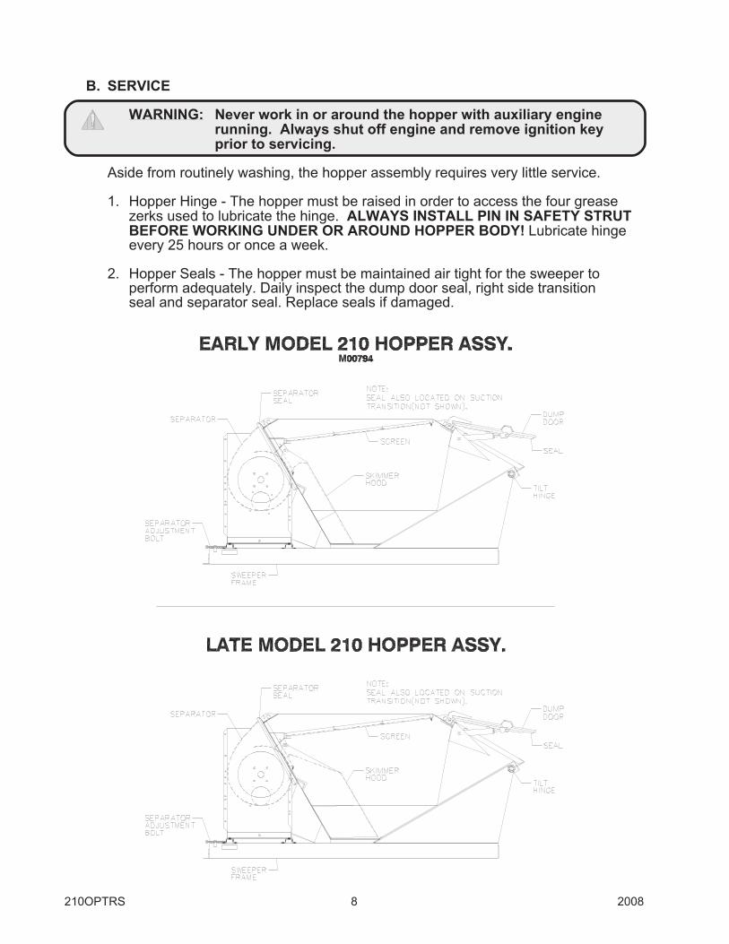
B. SERVICE
WARNING: Never work in or around the hopper with auxiliary enginerunning. Always shut off engine and remove ignition keyprior to servicing.
Aside from routinely washing, the hopper assembly requires very little service.
1. Hopper Hinge - The hopper must be raised in order to access the four greasezerks used to lubricate the hinge. ALWAYS INSTALL PIN IN SAFETY STRUTBEFORE WORKING UNDER OR AROUND HOPPER BODY! Lubricate hingeevery 25 hours or once a week.
2. Hopper Seals - The hopper must be maintained air tight for the sweeper toperform adequately. Daily inspect the dump door seal, right side transitionseal and separator seal. Replace seals if damaged.
2008 9 210OPTRS
BLOWER ASSEMBLY
A large turbine type blower is used in the TYMCO Model 210 to generate both the vacuum andpressure air stream used to sweep. The blower assembly is found on the left side of thesweeper (See Page 3) and is driven by an auxiliary engine through a sheave and belt system.
WARNING: Never reach into blower housing for any reason if blower powerband is installed.
WARNING: Always remove ignition key from sweeper control panel and/ordisconnect battery ground when working on or near the bloweror blower belt.
A. OPERATION
The blower begins to rotate as soon as the auxiliary engine is started. No clutch isused to engage or disengage the blower.
To increase the blower speed, turn the vernier throttle cable knob counterclockwiseto desired RPM.
Reverse procedure to decrease blower RPM. Use vernier override button on top ofthrottle cable knob only for emergency shutdowns.
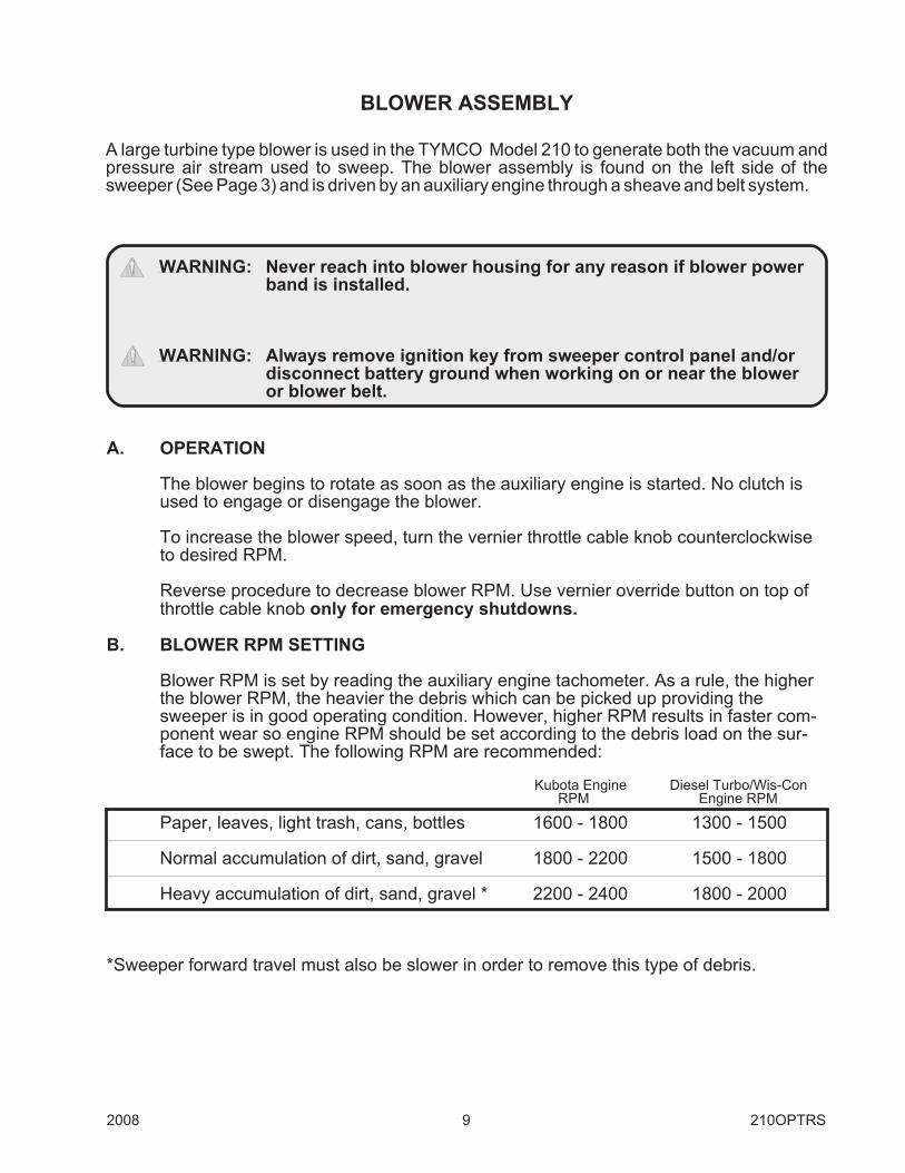
B. BLOWER RPM SETTING
Blower RPM is set by reading the auxiliary engine tachometer. As a rule, the higherthe blower RPM, the heavier the debris which can be picked up providing thesweeper is in good operating condition. However, higher RPM results in faster com-ponent wear so engine RPM should be set according to the debris load on the sur-face to be swept. The following RPM are recommended:
Kubota Engine Diesel Turbo/Wis-ConRPM Engine RPM
Paper, leaves, light trash, cans, bottles 1600 - 1800 1300 - 1500
Normal accumulation of dirt, sand, gravel 1800 - 2200 1500 - 1800
Heavy accumulation of dirt, sand, gravel * 2200 - 2400 1800 - 2000
*Sweeper forward travel must also be slower in order to remove this type of debris.

210OPTRS 10 2008
BLOWER SPEED - SRE OPTION
Auxiliary Engine RPM Blower RPM (Standard)
1400 17251700 21002000 2450
C. SWEEPING SPEEDS
The best sweeping speeds for the TYMCO SWEEPER will be between 1-10 MPHand will be dependent upon how heavily concentrated the debris. The lighter thecurb debris, the faster the sweeper can sweep. However, faster speeds will causefaster wear of the pick-up head curtains and skid plates.
The best all-around results are obtained when moderate blower RPM and moderatesweeping speeds are used. The following speeds are recommended:
MPH SPEED
Paper, leaves, light trash 1-10
Normal accumulation of dirt, sand, gravel 3-5
Heavy accumulation of dirt, sand, gravel 1-3
Traveling too slow when sweeping paper can sometimes cause it to build up in frontof the pick-up head; however, sand, dirt, and pea gravel must be swept slower toprevent trailing. Of course, the best way to find out what the TYMCO Model 210will pick up is to use it!
Higher speeds while maneuvering through repeated turns when sweeping a parkingarea will result in noticeable increased front tire wear.
CAUTION: Street sweeping requires a great deal of concentration by theoperator to avoid road hazards such as parked cars, pedestrians,chuck holes, etc. Judge street conditions and operate sweeperat a safe speed, regardless of how heavy or light the curb debris.

2008 11 210OPTRS
D. SERVICE
1. Wash out dust separator DAILY! Failure to clean separator will cause prematurewear of blower. Separator clean-out plug is located on the engine side of theseparator just below the flange bearing. Be cautious of belt drives when openingthe separator clean-out plug - SHUT OFF SWEEPER ENGINE!
(M01384)SEPARATOR CLEANOUT
PLUG
2. Two flange bearings are used on the blower assembly. One is located on theblower housing cover on the left side of the sweeper.

210OPTRS 12 2008
The second bearing is located on the right side of the separator next to theengine assembly. Both of these bearings require greasing once a week.
BEARING
(M01384)
CAUTION: Grease engine side bearing only when engine is not running.Proximity to belt drives is hazardous when engine is running. Alsonote that the hopper must be raised to access bearing. Always in-stall pin in lower safety strut before working beneath raised hopper.
When lubricating the bearing, be careful not to apply too much grease! Use manualhand type grease pump and pump the grease slowly into the bearing. A couple ofpumps is all that is necessary; too much grease will force out bearing seals andcause premature bearing failure.
3. Have blower belt tensioned after initial 10 hours of operation; then every 150 hoursof operation or once a month. A loose belt will allow slippage and result in poorsweeping performance as well as a damaged belt.

2008 13 210OPTRS
MODEL 210 SEPARATOR ASSEMBLY
(M00795)
When the 210 is being used, the blower draws air from the top of the hopper. As the air is beingdrawn, it passes first through the hopper screen and then into the separator inlet. Once in theseparator, the air begins to spin and centrifugal force throws dust particles against the separa-tor wall where it is then expelled through the skimmer slot. Once expelled, the skimmer hood in-side the hopper prevents the separated dust from being re-drawn into the separator inlet. Twoseparator belts are also used to prevent the expelled dust from being re-drawn back into theseparator inlet. Operation of the 210 without either the skimmer hood or the separator belts willcause accelerated wear of the blower and its housing.
210OPTRS 14 2008
HYDRAULIC SYSTEMSweeper operation is dependent upon a properly functioning hydraulic system. Componentssuch as the gutter broom, pick-up head lift assembly and hopper dump are all dependent on thehydraulic system for their proper operation.
The main hydraulic system components to be familiar with are:
A. Hydraulic Reservoir
B. Hydraulic Pump
C. Control Valves
A. HYDRAULIC RESERVOIR
The hydraulic reservoir is located on the left side of the sweeper between the caband dust separator (See Page 3). The reservoir oil capacity is 8 gallons (30.3 liters)and the operator must check the oil level daily! The sight gauge is located on thefront side of the hydraulic reservoir. If the oil level is low, fill reservoir before operat-ing sweeper. Use only 10W motor oil. (See Parts & Service Manual for EquivalentChart)
Located on the hydraulic reservoir is the hydraulic system oil filter. The filter shouldbe changed every 100 hours of sweeper service. The hydraulic oil filter is a spin-onautomotive type (TYMCO P/N 5010080).
NOTE: Change the break-in oil after initial 100 hours of operation. Then change oilonce every 12 months or 1000 hours, whichever occurs first. Drain hose islocated on the bottom of the reservoir.
CAUTION: Operator should never check for hydraulic leak using bare hand.High pressure used in the system could result in oil being injectedinto hand causing serious injury. Always turn sweeper off beforeservicing.
B. HYDRAULIC PUMP
The hydraulic pump is belt driven by the sweeper auxiliary engine. Hydraulic pumpbelt tension is critical for proper component operation. After initial 20 hours of opera-tion, re-tension belt. To access pump, hopper must be raised. Always install pin inlower safety strut before working under hopper!
Do not over-tension hydraulic belt! At center of belt span, use thumb and firmly de-press belt. A properly tensioned belt should deflect approximately 1/2 inch (12.7mm).
A 3/8" (9.5 mm) J.I.C. flared male fitting for testing the system pressure is located atthe output port on top of the pump. Use a test gauge rated to 3000 PSI (207 Bar) forsystem pressure checks.
CAUTION: Never Work Around belt drives when sweeper engine is running!

2008 15 210OPTRS
C. CONTROL VALVES
The hydraulic control valve assembly is used to control the flow of oil to the varioushydraulic components. The Model 210 valve assembly is located behind the door onthe left rear hopper hinge panel (See Page 3).
A relief valve is used to set the pressure for the Model 210 hydraulic system which is1500 PSI (103.5 Bar) for the standard left-hand gutter broom option. For Dual GutterBroom Option: 2500 PSI (172.5 Bar) for the primary pressure for the gutter broomsand 1500 PSI (103.5 Bar) for secondary pressure. Once set, no further adjustment isnecessary; however, at least once a year, or if components appear sluggish, havepressure setting tested. (Refer to Parts & Service Manual for procedure.)
The control valves are solenoid actuated, meaning that they are shifted by use ofelectric toggle switches. These toggle switches are located on the control consolepanel inside the cab - except the dump switch which is located externally. Shouldtoggle switch control fail to activate component, manual override buttons are pro-vided at each valve to manually engage component. Before manually shifting valves,make sure the wires are plugged into the valve solenoids. Should the switch fail toactivate the component, manual override buttons are provided on the top and bottomof each valve segment. Use the following procedure to engage the manual overridebuttons:
1. Locate valve segment not functioning.2. Set auxiliary engine RPM at idle.3. Use a screwdriver or similar device to push manual override button into valve
(considerable force must be exerted to overcome springs inside valve).
NOTE: Gutter broom can only be raised when manually shifting valve. If an at-tempt is made to lower gutter broom manually, bristles may rotate, butbroom will not lower due to lock valve engagement.
If a solenoid shorts out, it will cause the hydraulic system fuse to blow. The fuse is lo-cated at the control console assembly inside the cab (See Page 4). To replace sole-noid, refer to the Parts & Service Manual.

210OPTRS 16 2008
GUTTER BROOMThe Model 210 standard gutter broom utilizes a wafer type design which allows light debris,normally encountered in parking lot applications, to be brushed from the curb to the front of thesweeper’s pick-up head. Use the gutter broom only to clean next to the curb and gutters. Other-wise, keep it in the raised position to avoid unnecessary wear.
The gutter broom is controlled from inside the cab with an electric toggle switch (See Page 4).The sweeper auxiliary engine must be running in order for the gutter broom to work. When thetoggle switch control is sifted in the DOWN position, the gutter broom should begin to rotateand extend to the curb. Do Not force gutter broom into curb. Drive the truck so that bristle tipsjust contact curb; otherwise, the gutter broom may stall. ALWAYS use care when gutterbroom is down. NEVER ram gutter broom into curb or serious damage could occur.Also, NEVER back up with gutter broom lowered or it could possibly hang on stationaryobject resulting in damage.
Gutter broom rotational speed is directly related to the sweeper engine RPM. Full gutter broomrotation speed is achieved at 1500 RPM.
A. ADJUSTMENTS
1. Conventional Cab
The gutter broom will require regular bristle contact pattern adjustment. As thebristles wear, it may be necessary to decrease the gutter broom spring tension inorder to maintain bristle contact with the pavement surface. However, when newbristle segments are installed remember to re-tension gutter broom spring in orderto prevent premature bristle wear due to excessive down pressure.
The gutter broom tilt should be set as flat as possible. If set with too much tilt, exces-sive pressure will be felt by the bristle tips when contracting the pavement causingthem to bend severely and wear off prematurely. Also, too much bristle tilt will causebristles to jam up against the truck frame when gutter broom is raised, deformingbristle slope and causing gutter broom to “hop” while rotating.
Gutter broom tilt is adjusted by slightly loosening the single adjustment nut (SeePhotograph) just enough that bristles can be moved to desired position. The simpleball and socket joint used on the conventional cab gutter broom allows the maximumamount of bristle adjustment.
(M01219)

2008 17 210OPTRS
2. CAB-OVER
a. Spring - a long spring (1) is used to counter-balance the gutter broom assembly.As the gutter broom bristles wear out, this spring tension must be reduced bybacking off the eye bolt nut (2) used to attach spring to the boom arm. However,when new bristles are installed on gutter broom, the spring must be re-tensionedto counter the increased weight of the new bristles. Failure to re-tension thespring eye bolt nut will result in premature wear of the gutter broom bristles.Proper tension of the eye bolt nut for new segments is approximately one-halfway up the eye bolt.
b. Tilt - there is no established dimension for setting the gutter broom tilt becausestreet curbs and gutters vary from place to place. To tilt the gutter broom, locatedon the end of the boom arm are the wrist and hand. The hand adjustment allowsforward tilt; the wrist allows side to side tilt. Both require a 15/16" wrench to re-lease locking bolts. To adjust the hand, two bolts are found behind the torque mo-tor (3). Two bolts lock the wrist adjustment: one bolt is found on each side ofthe wrist bracket (4). When setting the gutter broom tilt, approximate the newbristle contact pattern for best results.
NEW BRISTLE CONTACT PATTERN
(M01383)
(M00762)

210OPTRS 18 2008
B. BRISTLE REPLACEMENT
It will be necessary to replace the bristles once they are worn out. To do so, use thefollowing procedures:
1. Lower gutter broom and turn off sweeper engine.
2. Turn ignition switch on, but do not start engine. Shift gutter broom toggle switchto UP position and observe the gutter broom spring to slightly raise the gutterbroom. Release the toggle switch once the gutter broom upward travel hasstopped and turn off ignition switch.
3. Remove bristle and disc assembly from hub by removing the three nuts locatedon bottom side of disc assembly.
4. Remove three bolts holding top disc to bottom disc and separate discs. Discardold bristle elements.
5. When installing new bristle elements, note line-up tabs on bristle segment ring.These tabs insert into slot provided on bottom disc (See Drawing below). Failureto install bristles correctly could allow them to rotate in disc.
6. For re-assembly, reverse procedure outlined above.
NOTE: Be sure to tension gutter broom spring properly (if necessary) to pre-vent premature bristle wear.
For more service information, consult your Parts & Service Manual or contact yourlocal TYMCO Dealer.
(M00692)
2008 19 210OPTRS
PICK-UP HEADThe pick-up head is the most important component of the TYMCO Model 210 Regenerative AirSweeper. But, because the pick-up head must be dragged on the pavement, it can be seriouslydamaged by careless operation. Even when the pick-up head is fully raised, It is still close to thepavement and care must be taken not to damage it in transit.
DO NOT:
1. Back up with pick-up head lowered.2. Raise pick-up head before lowering engine RPM.3. Increase engine RPM above idle before lowering pick-up head.4. Forget to raise pick-up for transit.5. Cut corners while in transit.6. Drive over speed bumps or divider turtles higher than two inches.
To lift debris from the ground, a 12" (30.5 cm) suction nozzle is located on the right side of thepick-up head. The sweeper blower draws air from the hopper creating a vacuum. A flexiblehose is used to connect the hopper vacuum to the pick-up head suction nozzle whereby debrisis lifted from the ground and deposited into the hopper. However, because the pick-up head is78" (198 cm) wide, some means must be used to move debris across to the suction nozzle.Just as debris is lifted into the hopper by the vacuum generated by the blower, the exhaust air ofthe blower is used to blow debris over to the suction nozzle. This is done by forcing the blowerexhaust air through an elongated pressure nozzle called the Blast Orifice. The blast orificeopening is 78" (198 cm) long with a 5/8" - 3/4" (16 - 19 mm) tapered opening (see Parts & Ser-vice Manual for adjustment procedures). The blower exhaust air is squeezed through this nar-row opening which compresses the air into a powerful jet that is used to blast debris from theground, forcing it over to the suction nozzle.
A. DESCRIPTION OF OPERATION
When at sweeping location, start sweeper auxiliary engine and let idle. Using thepick-up head toggle switch located on the control panel, lower pick-up head fully topavement (lift chains should be slack). Pull forward a few feet allowing curtains tofold under the pick-up head into the sweep position. Increase sweeper auxiliary en-gine speed to desired RPM and begin sweeping. Once sweeper auxiliary enginespeed is increased and the sweeper is moving forward, the pick-up head skid platesshould become firmly sealed against the pavement.
When sweeping operation has been completed, lowering engine RPM, continue trav-eling forward for a few feet to allow any debris under the pick-up head a chance tobe moved over to the suction nozzle and be picked up. Before raising the pick-uphead, throttle down sweeper engine to idle, then raise pick-up head. When fullyraised, the pick-up head will be secure against up-stop feet for sweeper transit.
PICK-UP HEAD MUST BE RAISED FOR TRANSIT!

210OPTRS 20 2008
B. PICK-UP HEAD CURTAINS
Because high velocity air is used by the pick-up head to remove debris from the pave-ment, the pick-up head must be sealed by rubber curtains to the pavement. These rub-ber curtains will incur wear as the pick-up head is dragged along the pavement and willrequire periodic replacement. Failure to replace worn out pick-up head curtains will re-sult in poor sweeper performance and excessively dusty conditions. Seal curtain life willdepend on pavement texture and sweeping speeds. Fast sweeping speeds increasefriction and accelerate curtain wear.
NOTE: Rubber curtain material is critical for proper wear life and sweeper perfor-mance. Use only TYMCO replacement curtains in order to guarantee sweeperperformance. To replace curtains, refer to Parts & Service Manual.
C. PICK-UP HEAD ADJUSTMENT
1. Blast Orifice - The adjustable blast orifice assembly must be moved in such a man-ner as to create a 5/8" (16mm) gap on the left tapering to a 3/4" (19mm) gap on theright. Failure to adjust the blast orifice gap each time the blast orifice curtain is re-placed will result in poor sweeper performance. (Refer to Parts & Service Manual)
2. Skid Plate Adjustment - The pick-up head is dragged on two skid plates (one oneach side of the pick-up head). These skid plates use carbide runners to prolongtheir service life. The skid plates are used to adjust the height of the blast orifice fromthe pavement. Refer to drawings for correct settings.
NOTE: Do Not lower skid plates in relation to the pick-up head when new curtainset is installed in order to prevent curtain wear, as lowering skid platesraises the blast orifice from the pavement and prevent curtains from prop-erly sealing. Poor sweeper performance will result.
3. Pick-Up Head Spring Adjustment - Four springs are used (two on each side) tosuspend the pick-up head from the sweeper carriage. The spring suspension is de-signed to give the pick-up head a floating effect as it is dragged along the pavement.This serves two purposes: one, it prolongs the service life of the carbide skid plates;two, it forms a shock absorption system that helps to protect the pick-up head fromsharp impacts. Failure to keep spring suspension system in proper adjustment willresult in premature wear of skid plates.
For proper spring adjustment, lower pick-up head and pull sweeper forward to foldcurtains under into the sweep position. With the pick-up head lowered and thesweeper engine at idle RPM, springs should hold front of skid plates 1/2" to 3/4"(12.7 to 19 mm) off pavement. If front of skid plates are contacting pavement, springtension should be increased until above description is observed. Rear of skid platesshould be set just above or lightly contacting the pavement (See Drawing). Once thespring tension is set, increased sweeper engine speed to 2000 RPM and pullsweeper forward. The increase in air velocity through the pick-up head should causepick-up head to drawn down and seal itself to pavement. The pick-up head oncedrawn down should then be easily lifted by one hand which demonstrates the float-ing characteristics desired.

2008 21 210OPTRS
4. Pick-Up Head Lock-Up Adjustment - The pick-up head is raised and lowered bymeans of a hydraulic cylinder which rotates a lift arm assembly. Two chains (one oneach side) attach the lift arms to the pick-up head. These chains are attached to thelift arms with an eye bolt (see Page 23). The pick-up head should fit snugly againstthe up-stops when fully raised. If not, check to see if the up-stops are bent. Ifup-stops are not bent, then use the lift chain eye bolts to take out slack in lift chains.
The pick-up head is locked in the UP or transit position hydraulically and electrically.A check valve in the hydraulic valve bank ensures the head from drifting down.
CROSS SECTION THRUMODEL 210 PICK-UP HEAD
(M00466)

210OPTRS 22 2008
MODEL 210 PICK-UP HEAD SETTINGS
(M00796)

2008 23 210OPTRS
MODEL 210 PICK-UP HEAD ASSEMBLY

210OPTRS 24 2008
PRESSURE BLEEDER
The pressure bleeder is a small door located on the pick-up head pressure ring just below thepressure hose. When the pressure bleeder door is opened by controls within the cab, part ofthe pressure air stream is diverted to the atmosphere. This causes the vacuum beneath thepick-up head to be intensified; thus, lifting the front curtain. This allows light debris to be drawnunder the pick-up head. This operation should be done only when necessary to pick up light de-bris and the pressure bleeder kept closed at all other times.
Open pressure bleeder door only when sweeping light debris;otherwise pressure bleeder should be kept closed.
(M01220)

2008 25 210OPTRS
DUST CONTROL SYSTEM
The optional dust control system is designed to control the normal amounts of dust created bythe operation of the sweeper under normal sweeping conditions. The dust control system (of-ten referred to as the water system) is only effective when the sweeper is operating properly.Problems such as bad door seals, worn pick-up head curtains, holes in the suction/pressurehoses can cause extremely dusty conditions which cannot be controlled by a properly function-ing dust control system.
A. OPERATION
The following procedure is recommended for operation of the TYMCO® Model 210dustcontrol system:
1. Fill the water tank. A 29 gallon (110 liter) water tank is located on the left side of thesweeper just under the dust separator (See picture below). The tank fill/drain valvehas a female adapter allowing the tank to be filled with a common garden hose. Thetank is full when water is observed to run out vent tube on top of tank.
2. Controls for the dust control system are located in the cab on the control consolepanel. To activate system, start sweeper engine, then turn on main water toggleswitch which activates the water pump. If the tank contains water, select the desiredwater distribution switches and water will continue to spray until sweeper engine isshut off, water toggle switch is turned off or water tank is emptied. If the water tankis emptied, the low water light will come on indicating that the water system has shutoff automatically.
3. At end of shift, fill tank and then drain to flush out tank.
(M01221)

210OPTRS 26 2008
B. SERVICE
There are essentially four service areas for the water system:
1. Water Tank2. Pre-Filter3. Water Pump4. Spray Nozzles
Service these areas routinely according to the following directions:
1. Water Tank - The water tank should be flushed at the end of each shift to removecontaminants. Fill tank and then allow to drain.
2. Pre-Filter - A pre-filter is located between tank and water pump to remove anycontaminants before they reach the pump. The pre-filter has a removable cleanoutbowl which should be removed and cleaned once a day. Use care not to lose thebowl gasket when cleaning or water system will not work due to air leak.
3. Water Pump - The heart of the TYMCO water system is an electric pump capable of5 GPM. The system relief valve is set at 25 PSI.
4. Spray Nozzles - The operator is responsible for keeping the spray nozzle tips cleanand spraying.
ATTENTION: On the Model 210 it is important to use only the correct outputspray tips in order to realize proper water system spray time andpressure.
a. If a spray nozzle is clogged, the entire tip assembly must be removed for clean-ing. To clean tip, use the edge of a knife or razor to clear tip spray slot. Grasp thetip between the index finger and thumb with slotted side facing up and strike thetip sharply against a clean, hard surface to dislodge blockage.
DO NOT USE DRILL TO MAKE ORIFICE LARGER!
b. To re-install tip, insert tip into cap and hand tighten cap to nozzle assembly. Holdtip in desired position with the use of pliers in one hand. With the other hand, usea wrench to tighten the cap which locks tip position.
WATER SYSTEMSERVICE AREAS
(M00768)

2008 27 210OPTRS
C. WINTERIZATION
To winterize the Model 210 water system, the system should be filled with a solution ofpropylene glycol. Follow procedures outlined below:
1. Disconnect siphon hose from water tank.2. Submerge hose end into container of propylene glycol.3. Turn ignition switch on. Turn water switch on until propylene glyco is observed to
spray from nozzles. Then turn water switch off.4. Make sure water tank is DRAINED!5. System is now winterized.
WISCONSIN POWER UNIT STARTING PROCEDURE:
If sweeper is equipped with the Wis-Con Power unit, follow the procedure below to start the en-gine.
1. Make sure the throttle is fully shut and the choke is OFF (Plate Open).
2. Engage the starter, spin engine for 3 seconds to allow engine speed to increase, thenpull the choke cable fully out (Plate Closed). Push back in when the engine fires. Chokeplate should not have to be closed for more than several seconds even in cold climates.
3. If the engine stalls, repeat the procedure, this time pushing the choke in slower after theengine fires.
4. Choking may not be necessary for hot restarts. If required, use only a quick pull of thechoke after the engine is spinning, with an immediate return to open position.

210OPTRS 28 2008
HAND HOSE OPTION
A simple, yet effective, optional feature offered on the Model 210 sweeper is the hand hose at-tachment. The hand hose was designed to allow the cleaning of those areas that the sweepercan not get into, such as corners, between posts, ditches, etc. However, when using the handhose, the street sweeping portion of the sweeper is disabled. The reason for this is that to usethe hand hose the hopper suction inlet must be blocked off. By doing this, all the hopper vacuumis diverted to the hand hose. To operate the hand hose, use the following instructions:
1. Park the sweeper next to area to be cleaned within range of the hand hose nozzle.
2. Insert the shutter plate (stored inside the chassis cab) between suction transition sealand hopper inlet.
3. Remove hand hose from transit hangers.
4. Open hand hose door and swing hand hose assembly around and clamp to handhose port.
5. Start the auxiliary engine; lower the pick-up head and turn on the hopper water sys-tem which supplies water to the hopper spray nozzle.
6. Set engine RPM according to the debris load:
Engine RPMPaper, leaves, cans & bottles 1500-1800Heavy dirt and gravel 1800-2200Water, mud, shallow catch basin 2000-2200
NOTE: When using hand hose to remove water or mud, do not submerge end ofnozzle. The hand hose picks up debris by the in-rush of air; if no air isallowed to enter nozzle, then no debris will be picked up. Hold nozzle endjust slightly above water or mud for best results.
WARNING: Never direct hand hose nozzle at another person or serious injurymay occur.
7. Once the hand hose operation is completed, always turn hopper water and auxiliaryengine off and unlatch hand hose from port before swinging assembly around to re-clamp to transit hangers.
8. After hand hose has been clamped to transit hangers, remove shutter plate fromhopper suction inlet. Failure to do so will render sweeper inoperable as debris frompick-up head is blocked off from hopper.

2008 29 210OPTRS
AUTO SWEEP INTERRUPT OPTION
DESCRIPTION OF OPERATION
WARNING! The ASI System does not automatically inhibit the sweeper frombacking up. The ASI System signals the operator when all thesweeper systems are safe to back up. Backing the sweeper is stillin the control of the sweeper operator and care must be taken toavoid accident or injury from backing sweeper.
Manual/Auto switch must be in Auto position for ASI to work. Upon placing the transmis-sion gear selector in the reverse position, the auxiliary engine will automatically be idled andthe sequence of the raising operations will begin. Also, to notify the operator that the sequenceof operations is in progress, a red warning light located on the console will start flashing. Assoon as the pick-up head is fully raised, the green light will turn on to notify the operator that thesweeper is ready to back up. To resume sweeping, the transmission must be taken out of re-verse (turning the red light off) and the INTERRUPT/RESET switch can then be pressed (turn-ing the green light off) which will automatically lower the gutter broom(s), if previously ON, andlower the pick-up head. Operator must manually increase the throttle RPM!
FUNCTION
The pick-up head is designed to operate (or be pulled) in only the forward sweeping direction.Therefore, to prevent damage to the pick-up head assembly, the sweeper should never be“backed-up” with the pick-up head in the DOWN position. Before backing the sweeper, the op-erator should ALWAYS return the auxiliary engine to the idle speed, and raise the pick-up headand gutter brooms. The Auto Sweep Interrupt (ASI) circuit was designed to automatically ac-complish this sequence of operations in an elapsed time of approximately 10 seconds.
When the ASI System is enabled, to interrupt sweeping for backing, the auto-sequence of op-erations begins immediately when the sweeper chassis is shifted into reverse or by pressing aINTERRUPT/RESET switch mounted at the sweeper control console. The auto-sequence ofoperations is in the following order:
1. The auxiliary engine is idled and the gutter broom(s) and the BAH (Broom AssistHead) broom, if equipped, are stopped.
2. The water system is turned OFF.3. The left gutter broom is raised.4. The right gutter broom is raised.5. The pick-up head is raised (Including the BAH broom.)
To reset the sweeper in order to resume sweeping, the transmission must be taken out of re-verse and the INTERRUPT/RESET switch pressed. All systems, except the throttle, will returnto their previous mode. The gutter broom(s) will automatically lower, the water system will re-sume, the pick-up head will lower if each were previously ON. After an approximate 4 secondtime delay (which is adjustable),to insure that the pick-up head is on the sweeping surface, theoperator may pull forward and manually raise the auxiliary engine speed and resumesweeping.

210OPTRS 30 2008

2008 31 210OPTRS
REGENERATIVE AIR SWEEPER®WARRANTY
TYMCO REGENERATIVE AIR SWEEPERS® are warranted to be free fromdefective materials and workmanship for a period of 12 months or 1,000hours from date of delivery and such period being hereinafter referred to as“warranty period”. It is the sole obligation of Seller with respect to this war-ranty period to replace free of charge, F.O.B. Waco, Texas, any part or partswhich may prove to be defective due to defective workmanship or materialswithin the warranty period provided no disarrangement of using unauthorizedparts or changes to the machinery be made voluntarily or by incompetency,carelessness, negligence, accident or need of attention upon the part ofpurchaser, agents, employees or other parties.
This warranty shall not cover normal maintenance and adjustments, and thesame not include nor shall Seller be liable or responsible for material for nor-mal wear and usage for any damages by reason of loss of production, downtime or loss of profits or income arising from any reason whatsoever. Sellerreserves the right to change the design and construction of said sweeperwhen in its sole opinion any such change represents an improvement of thesweeper. All outside purchased equipment and accessories are guaranteedonly to the extent that the manufacturer’s guarantee may apply and are notsubject to this warranty nor to any implied warranty.
This warranty is in lieu of all other warranties, expressed or implied. No per-son is authorized to give any other warranties or to assume any other liabilityon the Company’s behalf unless made in writing by the Company, and no per-son is authorized to give any warranties or to assume any liabilities on theSeller’s behalf unless made in writing by the Seller.