displays of his work. Large silk pieces occupied McCarthy Mall ...

18
Mobile Robot with Preliminary-announcement and Indication of Scheduled Route and
Occupied Area using Projector
Takafumi Matsumaru Shizuoka University
Japan
1. Introduction
We are proposing approaches and equipments for preliminarily announcing and indicating to people the upcoming operation of mobile robot moving on a two-dimensional plane. We have developed four kinds of prototype robot in which our approaches are realized. This chapter focuses on the projection robot PMR-5 and the revised version PMR-5R, in which projection equipment projects a two-dimensional frame on a running surface and the frame contains the information about the robot’s upcoming operation.
2. Background and Objectives
2.1 Preliminary-announcement and indication of upcoming operation
Human beings interact signaling their own and predicting others’ actions and intentions nonverbally through body language, hand gestures, facial expressions, and whole body operations. Most people moving through a crowd, for example, find little trouble plotting a passage through a forest of bodies without bumping into or otherwise upsetting or needlessly distracting others. Human beings hone social and physical skills that make their movement practically second nature based on a sense of affinity, familiarity, common appearance – sharing what they like to call “common sense”. Robots call up exactly the opposite reaction – disaffinity, unfamiliarity, uncommon appearance – no sharing of the common sense that would make robot movement predictable to people – or human movement predictable to robots. If I see that you are bent forward walking fast and your eyes on a distant goal, I can predict that getting out of your way is appropriate and I can guess how fast I’ll have to move to let you through. If, however, you are a robot, I probably have no idea how to deal with your movement – how fast you might walk and what direction you may take. This lack of shared knowledge and common sense between human and artificial organisms is what has made their interaction such a problem – the simplest aspect of which is to avoid the risk of contact and collision. We are studying functions to notify people of an artificial organism's approach upcoming and intentions before it moves in order to avoid the risk of unintended contact or collision between people and artificial organism, focusing on mobile robots or transport vehicles moving on a two-dimensional plane (Fig. 1). Such robots should announce their direction
www.intechopen.com

Mobile Robots Motion Planning, New Challenges
362
and speed of movement. Such announcement should be simple and immediately understandable enough to be acceptable to people. It must also be easy for people to understand based on their common sense. We have proposed four approaches categorized in two types to preliminarily announce and indicate the speed and direction of upcoming movement of mobile robot as shown in Table 1 (Matsumaru & Hagiwara, 2001a; Matsumaru, 2004). The first type announces the state of operation just after the present: lamp method and blowout (telescopic arrow) method, and the second type indicates the operations from the present to some future time continuously: light ray method and projection method. The effect of preliminary-announcing and indicating the upcoming robot operation, the difference according to methods, and the appropriate timing to announce have been examined by using a software simulation before the hardware equipments that made the approaches embodiment were designed and manufactured (Matsumaru & Hagiwara, 2001b; Matsumaru et al., 2003c, 2003d; Matsumaru et al., 2004).
Figure 1. Contact and collision avoidance
(1) Announcing state just after the present (2) Indicating operations continously
(a) Lamp (b) Blowout (c) Light ray (d) Projection
Several lamps are set on the top. Direction of movement is by turning the lamp on. Speed of movement is by blinking speed or color of lamp.
Blowout put on a turntable is set on the top. Speed of movement is by length of blowout. Direction of movement is by tip direction of blowout.
Light ray draws scheduled route on running surface from present to some future time using pan-tilt mechanism. Situation on the way can be indicated.
Not only scheduled route but also state of operation, such as stop or going backward, can be displayed in the projected frame.
Table 1. Proposed approaches
Main content to announce and display in the second type of proposed approaches is the scheduled route on running surface from the present to some future time.
www.intechopen.com

Mobile Robot with Preliminary-announcement and Indication of Scheduled Route and Occupied Area using Projector
363
Light ray method is intended to draw only the scheduled route (Table 1 (c)). The scheduled route expressed with the afterimage of radiant irradiated on running surface was monochrome (red or green) on the developed robot PMR-1, which embodied the light ray method, since the a single colour laser pointer was used as a light source (Matsumaru et al., 2006a, 2006b). Outward appearance and main specifications of PMR-1 are shown in Fig. 2 and Table 2. Period to display the scheduled route is predefined, such as until 3-second-later. Drawn route expresses the direction of movement directly. Strong point of light ray method is the “situation on the way” can be indicated, such as whether going the shortest route directly or going via somewhere to bypass something when moving to some place. However information about time is insufficient in the route drawn in a single colour. The speed of movement can be expressed with the length of drawn route, since we decide beforehand until how many seconds after the present the scheduled route is displayed. However it is only the average speed in that period. If we decide the route is drawn until 3-second-later, it is recognized whether fast or slow as the average speed during three seconds by the length of drawn route, then a change of speed in the period is not expressed. For example, although it will be slow from the present to 1-second-later, it will become fast from 1-second-later to 2-seconds-later and it will come back to be slow after 2-seconds-later again. Moreover the problem is it is difficult for people to understand the rule at a glance since only the afterimages of radiant is the source of information. Even if people understand the afterimage of radiant expresses the scheduled route, careful observation for a while and matching between expressions and operations are required to understand both the route of movement during some predefined period and the relation between the length of drawn route and the exact amount of robot’s speed.
Figure 2. Outward appearance of PMR-1R
Trailing wheel
Driving wheel
Laser pointer
Mirror
Pan motor
Tilt motor
PC
Scheduled route
www.intechopen.com

Mobile Robots Motion Planning, New Challenges
364
Projection method is developed from the light ray method (Table 1(d)). A projection equipment projects a two-dimensional frame on a running surface to indicate both the scheduled route and the states of operation such as stop and going backward. Internal condition of the robot such as remaining battery charge and warning on worn parts or overheating apparatus can also be displayed in the frame. If the projected frame is sufficiently large, the projector can be fixed to the robot and any moving portion for preliminary-announcement and indication function becomes unnecessary. Toyota Motor Corp. announced “road surface depiction (laser tactile sense)” in the autumn of 2004 similar in irradiation or projection on a running surface (Toyota, 2004). However this mainly targets collision avoidance among vehicles, not intending upcoming movement of the vehicle for pedestrians.
Item Specification
Mobile mechanism two-wheel drive
Max. mobility 36 mm/s, 41.4 deg/s
Size D460-W480-H910 mm
Weight 30.0 kg
Table 2. Main specifications of PMR-1R
2.2 Conventional Projection Interface
Human interface (HI) means the coupling part between people and a machine or a computer, and it indicates the scheme or structure to make artificial organisms user-friendly in a narrow meaning. Display equipment is commonly used as a human interface to show visual information through a screen, including CRT (cathode-ray tube), LCD (liquid crystal display), and projector (projection equipment). As a multifunctional interface containing some display unit for visual information, Digital Desk (Wellner, 1991) changed the previous indirect relationship between a user and a computer where a screen and a mouse device are used. On Digital Desk, three functions, visual display function (desktop is projected on a very common desk), control function (user's own fingertip is used to direct operations instead of mouse and icon), and registration function (documents and objects like doll are taken in, for example, using a camera and information is processed on desktop electronically) were considered. Researches on these three functions include Enhanced Desk (Koike et al., 2001), Sensetable (Patten et al., 2001), Illuminating Clay (Piper et al, 2002), SmartSkin (Rekimoto, 2002), Lumisight Table (Kakehi et al., 2005), Attentive Workbench (Nikaido et al., 2005), and so on. There are also some researches of projection on a wall instead of a desktop (Matsushita, 1997 and Nakanishi, et al. 2002). Those are mainly concerning human-machine interaction on visual information. Consequently reaction function (reaction force against operation is presented to the user) is studied as fourth function of Digital Desk. Researches include, for example, PSyBench (Physically Synchronized Bench) (Brave et al., 1998), Visual Haptic Workbench (Brederson et al., 2000), Actuated Workbench (Pangaro et al., 2002), and Proactive Desk (Noma et al., 2004). However those interactions are bounded between people and virtual environment even via physical force sense. As an interface for tasks to actual objects, projector is commonly used to present information from remote supporter to on-site worker in order to support and prescribe from remote site
www.intechopen.com
Mobile Robot with Preliminary-announcement and Indication of Scheduled Route and Occupied Area using Projector
365
(Hiura et al., 2003; Machino et al., 2005). RFIG (Radio Frequency Identification and Geometry) lamps are interesting as an interaction of information in real workspace (Raskar et al., 2003). Using an active RFID tag with photo electronic sensor and a handheld projector with camera, both the ID and position of a tag within a limited area are recognized by projecting grey code pattern light from the projector, then the related information is projected on the object. Some research uses projector as an interface between people and robot, for example, in order to teach operations to a robot (Terashima & Sakane, 1999; Sato & Sakane, 2000; Yamashita & Sakane, 2001). Those are mainly for off-line teaching, and the operation and direction to working robot are seldom taken into consideration. About the actually working robot, the information sharing function on manipulator (Wakita et al., 2001) is examined, as a method of showing people around the operational information of the robot. However this is only for ground-fixed manipulator.
3. Projection Robot, PMR-5 and PMR-5R
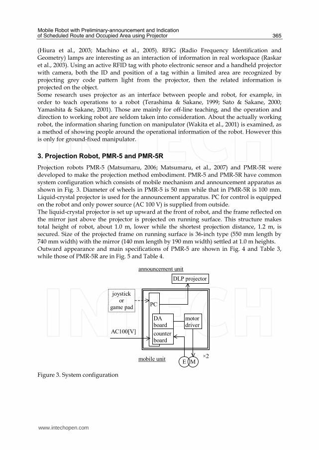
Projection robots PMR-5 (Matsumaru, 2006; Matsumaru, et al., 2007) and PMR-5R were developed to make the projection method embodiment. PMR-5 and PMR-5R have common system configuration which consists of mobile mechanism and announcement apparatus as shown in Fig. 3. Diameter of wheels in PMR-5 is 50 mm while that in PMR-5R is 100 mm. Liquid-crystal projector is used for the announcement apparatus. PC for control is equipped on the robot and only power source (AC 100 V) is supplied from outside. The liquid-crystal projector is set up upward at the front of robot, and the frame reflected on the mirror just above the projector is projected on running surface. This structure makes total height of robot, about 1.0 m, lower while the shortest projection distance, 1.2 m, is secured. Size of the projected frame on running surface is 36-inch type (550 mm length by 740 mm width) with the mirror (140 mm length by 190 mm width) settled at 1.0 m heights. Outward appearance and main specifications of PMR-5 are shown in Fig. 4 and Table 3, while those of PMR-5R are in Fig. 5 and Table 4.
DLP projector
PC
motor driver
DA board
announcement unit
×2
AC100[V]
joystick or
game pad
MEmobile unit
counter board
Figure 3. System configuration
www.intechopen.com

Mobile Robots Motion Planning, New Challenges
366
Figure 4. Outward appearance of PMR-5
Figure 5. Outward appearance of PMR-5R
Trailing wheel
Driving wheel
Mirror
PC
Projector
Occupied width
Trailing wheel
Driving wheel
Mirror
PC
Projector
Scheduled route
www.intechopen.com
Mobile Robot with Preliminary-announcement and Indication of Scheduled Route and Occupied Area using Projector
367
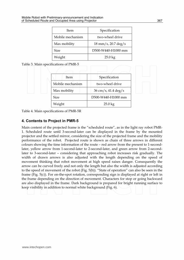
Item Specification
Mobile mechanism two-wheel drive
Max mobility 18 mm/s, 20.7 deg/s
Size D500-W440-H1000 mm
Weight 25.0 kg
Table 3. Main specifications of PMR-5
Item Specification
Mobile mechanism two-wheel drive
Max mobility 36 cm/s, 41.4 deg/s
Size D500-W440-H1000 mm
Weight 25.0 kg
Table 4. Main specifications of PMR-5R
4. Contents to Project in PMR-5
Main content of the projected frame is the “scheduled route”, as in the light ray robot PMR-1. Scheduled route until 3-second-later can be displayed in the frame by the mounted projector and the settled mirror, considering the size of the projected frame and the mobility performance of the robot. Projected route is shown as chain of three arrows in different colours showing the time information of the route – red arrow from the present to 1-second-later, yellow arrow from 1-second-later to 2-second-later, and green arrow from 2-second-later to 3-second-later – considering that approaching robot increases risk gradually. The width of drawn arrows is also adjusted with the length depending on the speed of movement thinking that robot movement at high speed raises danger. Consequently the arrow can be curved freely and not only the length but also the width is adjusted according to the speed of movement of the robot (Fig. 5(b)). “State of operation” can also be seen in the frame (Fig. 5(c)). For on-the-spot rotation, corresponding sign is displayed at right or left in the frame depending on the direction of movement. Characters for stop or going backward are also displayed in the frame. Dark background is prepared for bright running surface to keep visibility in addition to normal white background (Fig. 6).
www.intechopen.com

Mobile Robots Motion Planning, New Challenges
368
Straight-fast Straight-slow (a) Speed of movement: length/width of chained arrows
Turn On-the-spot rotation (b) Direction: curved condition of arrows or sigh
Going backward Stop (c) State of operation: characters
Figure 5. Exact descriptions on PMR-5
www.intechopen.com

Mobile Robot with Preliminary-announcement and Indication of Scheduled Route and Occupied Area using Projector
369
(a) Going forward (b) Stop Figure 6. Projected frame with dark background
State of operation to display is roughly divided into four – going forward, on-the-spot rotation, going backward, and stop. (1) Distinction of state of operation:
First, the state of operation to display is distinguished from the speed instruction, rotation
factor xJ and translation factor xJ , which is taken in from some input device every 50 ms
and accumulated in the instruction buffer during the latest three seconds.
• There is an instruction in which translation factor is negative. → Going forward (because the used joystick is a flight simulator type)
• There is an instruction in which translation factor is zero but rotation factor is not zero. → On-the-spot rotation
• There is an instruction in which translation factor value is positive. → Going backward
• There is an instruction in which both translation factor and rotation factor are zero at the same time. → Stop
State of operation displayed in the frame is independent each other even if two or more states are distinguished simultaneously. Accordingly multiple states may be displayed in the frame at the same time, for example, when it does stop after going forward. (2) Contents and method to display:
Secondly, contents to display are refreshed in every 50 ms – same as command input cycle. Only one projector is equipped on the developed robot so that it can project only one frame of a fixed size to predefined position in front of the robot. a) Going forward: Going forward is expressed with the chain of three arrows in which the scheduled route is expressed as the long axis of arrows in different colors showing the time information of the route, although in the light ray robot PMR-1 the scheduled route drawn by laser pointer is a simple line in a single color (movement afterimage of red radiant) and the length of drawn route only shows the average speed during three seconds. Sixty polygons are prepared from sixty speed instructions acquired every 50 ms during the latest three seconds. Those are connected perpendicularly and form three arrows after transformed so as to look like the correct form. One arrow consists of twenty polygons – one
triangular polygon aPo for the tip of arrowhead, seven quadrangle polygon bPo for the
arrowhead except tip, and twelve quadrangle polygon cPo for the rod of the arrow (Fig. 7).
www.intechopen.com

Mobile Robots Motion Planning, New Challenges
370
Poa
Pob
Poc
(a) Straight (b) Turn Figure 7. Each arrow consists of twenty polygons
Three arrows are formed connecting sixty polygons from base to tip using instructions from the oldest to the latest one (Fig. 8(a)). When a new speed instruction is acquired, the polygon
A shaped using the newly acquired instruction is arranged at top of green arrow, while sixty polygons are shifted to the base of arrows (toward the robot) (Fig. 8(b)). The position of
polygon A (top of green arrow) shows the position where the robot will reach three
seconds later. When the next speed instruction is acquired, the polygon A is shifted once to
the base of arrows (toward the robot) and the polygon B which is shaped using the new
instruction is arranged at the top of green arrow (Fig. 8(c)). Thus the polygon A is shifted to the base of arrows (toward the robot) one by one as time goes on. It reaches the base of arrows three seconds later, then the corresponding speed instruction is performed and the robot moves in that manner (Fig. 8(d)).
green
yellow
red
speed command A
A
(a) Initial condition (b) Command A input
speed command B
B
A
speed command
B
A
(c) Next command B (d) Three seconds later Figure 8. Flow of polygons made from input command
www.intechopen.com

Mobile Robot with Preliminary-announcement and Indication of Scheduled Route and Occupied Area using Projector
371
The rate of the length of polygon along the direction of route against the robot's speed of movement was determined by trial and error so that the arrows might agree with the actual robot movement. Moreover the rate of the width of polygon against the amount of speed instruction was also determined by trial and error considering the visual quality of the arrows. In any case all polygons are connected perpendicularly after calculating the inclination angles and carrying out the coordinate transformation using the speed
instruction, rotation factor xJ and translation factor yJ . The form of each polygon is
adjusted so that the scheduled route may be expressed smoothly even though any speed instruction, not only going straight but also arbitrary rotation, is given. Specifically the following processing is performed (Fig. 9). First, the speed of movement of
wheels on both sides nV1 , nV2 mm/s is obtained from each speed instruction value xnJ ,
ynJ of sixty pieces for three seconds ( n =1~60). The difference of movement distance nS
mm between right and left wheels during 50 ms and the rotation angle nrot rad are
computed, where Lw mm is the distance between wheels.
( ) 05.021 ×−= nVnVnS (1)
⎟⎠⎞⎜⎝⎛−= Lw
nSnrot 1tan (2)
Next, the rotation angle nsumrot rad of the n -th polygon and the displacement ( nx , ny )
by the speed instruction are calculated in the coordinates on the projected frame, where the variable a is the coefficient determined by trial and error in order to make the actual
movement and the projected frame in agreement.
∑=
=n
nnrotnsumrot
1 (3)
( ) ( )nsumrotynJanx sin×−×= (4)
( ) ( )nsumrotynJany cos×−×= (5)
Then the central point ( nX , nY ) of the n -th polygon from the original position ( 0X , 0Y ),
which is shown on the bottom line in the figure, is computed on the frame.
∑=
+=+−=n
nnxXnxnXnX
101 (6)
∑=
+=+−=n
nnyYnynYnY
101 (7)
The position of both ends of the bottom line of the n -th polygon are calculated just with
computing the position where it is apart from the central point only by the width nd of
arrow which is decided from the position of the polygon in the arrow (whether tip,
www.intechopen.com

Mobile Robots Motion Planning, New Challenges
372
arrowhead or rod) and the amount of speed instruction. By repeating these procedures the scheduled route can be displayed as three arrows correctly.
( )( ) ⎥⎦
⎤⎢⎣⎡
×+
×+=⎥⎦
⎤⎢⎣⎡
nnn
nnn
sumrotdY
sumrotdX
Y
X
sin
cos
( )( ) ⎥⎦
⎤⎢⎣⎡
×−
×−=⎥⎦
⎤⎢⎣⎡
nnn
nnn
sumrotdY
sumrotdX
Y
X
sin
cos
⎥⎦⎤⎢⎣
⎡0
0
Y
X
⎥⎦⎤⎢⎣
⎡n
n
Y
X
nsumrotnd
nd
⎥⎦⎤⎢⎣
⎡−
−
1
1
n
n
Y
X
⎥⎦⎤⎢⎣
⎡−
−
2
2
n
n
Y
XX
Y
nPo
Figure 9. Position of quadrangular polygon in the frame
b) On-the-spot rotation/Going backward/Stop: In case of on-the-spot rotation, going backward, and stop, the treatment is the same in displaying the state of operation. The corresponding sign for on-the-spot rotation and the characters of BACK or STOP for going backward and stop are displayed in the frame respectively. Those are always displayed in grey, while displayed in yellow if the operation is performed within three seconds and the color turns in red when the operation is executed at that time.
5. Contents to Project in PMR-5R
Mobility performance of PMR-5R is doubled from PMR-5 with replacing the driving wheels to those of double diameters leaving the same driving mechanisms. Therefore the projected frame with the same size as on PMR-5 can inform the upcoming operation until 1.5-second-later. In PMR-5R the upcoming occupied width and area during robot's travelling are displayed on the frame by drawing a belt with the same width as the robot. People will never come into contact nor collision with robot and safety will be secured only if they do not just step on the belt. The belt is colour-coded based on the traffic signal – red part from the present to 0.5-second-later, yellow part from 0.5-second-later to 1.0-second-later, and green part from 1.0-second-later to 1.5-second-later – like arrows in PMR-5 (Fig. 10(a)). The belt can be curved freely and the length of belt is adjusted depending on the speed of movement (Fig. 10(b)). The belt has semitransparent striped pattern which moves towards robot synchronizing with robot movement. Accordingly it looks like the belt is fixed on the floor and the robot moves rewinding the belt. That makes easy to understand the meaning of the projected belt for people around. Moreover we decide to display the grey arrows along the center of belt in order to make easier for people to understand the scheduled route. The arrows are also curved freely and their width and length are adjusted depending on the speed of movement as in PMR-5. State of operation can also be seen in the frame (Fig. 10(c)). For on-the-spot rotation, corresponding sign is displayed at right or left in the frame depending on the direction of movement. Characters for stop or going backward are also displayed in the frame.
www.intechopen.com

Mobile Robot with Preliminary-announcement and Indication of Scheduled Route and Occupied Area using Projector
373
Straight-fast Straight-slow (a) Speed of movement: length of belt and length/width of chained arrows
Turn On-the-spot rotation (b) Direction: curved condition of belt/arrows or sigh
Going backward Stop (c) State of operation: characters
Figure 10. Exact description on PMR-5R
Sixty polygons are prepared from thirty speed instructions acquired every 50 ms during the latest 1.5 seconds. That is, every speed instruction is dual partitioned from which two
www.intechopen.com

Mobile Robots Motion Planning, New Challenges
374
polygons are made to let the drawn belt look smooth (Fig. 11). Processing procedures to draw the belt and arrows are the same as in PMR-5.
Poa
Pob
Poc
Width of robot
(a) Straight (b) Turn Figure 11. Each part of belt consists of twenty polygons
Three kinds of striped pattern on color coding as bright tone and dark tone of polygons are
prepared. When a new speed instruction is acquired, two polygons A shaped using the speed instruction are arranged at tip end of the belt, while sixty polygons are sifted toward the robot (Fig. 12(a)). The corresponding polygons to form the part of arrows are also shaped as in PMR-5 at the same time, which are not shown in the figure. When the next speed instruction is acquired, the previous polygons are shifted to the robot keeping their
colour tone. And new two polygons B shaped using the new instruction with decided
colour tone are arranged at tip end of the belt (Fig. 12(b)). Two polygons A reach the bottom end of belt 1.5 seconds later, then the corresponding instruction is performed and the robot moves in that manner.
Par
t of
bel
t fo
r 500 m
s
Width of belt
A
B A
C B
A
Robot side
Outside
(a) T=t0 (b) T=t0+50ms (c) T=t0+100ms Figure 12. Flow of striped pattern of polygons
6. Discussion
In the questionnaire evaluation (Matsumaru, 2007b), PMR-5 has received the highest evaluation score comparing with other three prototype robots, eyeball robot PMR-2 (Matsumaru et al, 2003a, 2003b; Matsumaru et al, 2005), arrow robot PMR-6 (Matsumaru et al, 2001; Matsumaru, 2007a), and light ray robot PMR-1. In the experimental examination in simulated interactive situation between people and robot, the passing each
www.intechopen.com
Mobile Robot with Preliminary-announcement and Indication of Scheduled Route and Occupied Area using Projector
375
other and the positional prediction, we have clarified that the method of indicating operations from the present to some future time continuously is effective when a person wants to avoid contact or collision surely and correctively owing to the feature that complicated information can be accurately transmitted of PMR-5R (Miyata et al., 2007). Here the knowledge and consideration obtained through the research project are summarised as follows. (1) Artificial mechatronic system which moves its body physically
This research is aimed at artificial mechatronic systems which coexists with people like a human-friendly robot. We are willing to derive some benefit from such robot moving its body physically. The research is inspired from awareness of the issues that people may feel threat and receive sense of incongruity from existing human-friendly robot because it is difficult to understand the function and performance and the upcoming operation and intention of the robot only from its outward appearance. Accordingly there is a risk of contact or collide between people and robot. There should be two approaches to solve the problem. First approach is to design the structure and movement of robot so that it is easy to understand and predict its function and upcoming operation from its appearance. Second approach is to superimpose a new function to preliminary-announce and indicate its upcoming operation. This research takes the latter. The function to preliminary-announce and indicate the upcoming operation of robot aims at providing it to those who are willing to react actively due to the information. Consequently the robot assumed here is supposed to have some safety function to detect obstacles and people around and avoid them autonomously. We do not assume that the robot comes into contact with those who have neither awareness nor interest on the robot movement. What to emphasize here is that it is insufficient even if a robot does not contact with people. It is also important that robots never pose a threat to people and people can live together with robot comfortably without anxiety. (2) Sensory perception to be used
Each of four proposed methods complains to people's visual sense. If sound or voice is used to transmit information through auditory sense, information can be transmitted to everyone around, including those who do not want or desire it. Moreover sound or voice disturbs public peace. Accordingly only in the case that has a substantial need and requires emergency to transmit information to everyone around for safety reason, a robot might utter sound or voice, like heavy vehicles when turning at crossing. Since we decided to use visual sense here, we considered the method should be intelligible in which people can understand the shown contents immediately even at a glance, instead of taking a long looking. For that purpose it is necessary to take into consideration general common sense and customs, popular prejudice, basic knowledge stored through ordinary experiences, etc. (3) Kind of information to transmit
Direction indicator or winker lamp of passenger cars has a serious problem by expressing several meanings only with a single sign of blinking – turn (more various when including curvature factor and selection of corner to turn), lane changing, pulling over to the kerb (following up with parking), etc. It is difficult to setup the relation between sign and meaning. Especially when we want to transmit many kinds of information, namely various robot operations, the kind of sign becomes varied. Therefore it is difficult to memorize the meaning corresponding to each sign if the difference among signs is too
www.intechopen.com
Mobile Robots Motion Planning, New Challenges
376
large. On the contrary it is easy to confuse with each other when various signs are very similar. (4) Announcing state just after the present
Eyeball robot PMR-2 admits some interpretation between robot operation and sign for announcement, while arrow robot PMR-6 has direct connection between them. It is comparatively intelligible that the direction of movement is shown as eye positioning in the display, because the gaze is one of the keys to guess other's intention among people. Arrow is intelligible for everyone even at first sight, since it is commonly used in daily life and usually employed to express the direction. However it is difficult to show the speed of movement quantitatively by the degree of eye opening or the size of arrow. Especially on the speed of movement these two expressions might be used effectively after looking at the sign of moving robot and storing their knowledge. Accordingly these expressions will be effective in the situation and scene in which the information about the direction of movement has priority rather than that about the speed of movement. In the questionnaire evaluation, not a few people admired the eyeball expression as social and friendly due to personification and also the arrow expression as intelligible owing to straightforwardness and lucidness. Therefore those expressions will become candidates to examine for usage with greater importance to sociableness or lucidity. (5) Indicating operations continuously
Light ray robot PMR-1 displays the scheduled route in a single colour as line expression, while projection robot PMR-5 indicates the occupied area in multiple colours as field expression. Line expression is effective in contact avoidance even for small-size robots. Field representation is valid for wide-width organisms compared with human body like automobiles. When it is difficult to project a large frame, for example, by restriction of projection equipment, drawing borderlines on both sides can be considered to indicate occupied area in which the organism is going to pass through. These two methods of drawing lines and projecting frame by light have a big advantage that information can be indicated anywhere without special maintaining. However it is supposed that the surface to draw or project is plane with little unevenness and the environment should be under the right condition in which the reflected light is clearly visible. Accordingly those expressions will be useful in mobile robot which moves indoor on a floor at first. (6) Procedure to design and apply as interface
We have proposed and examined four methods, but we don't have to determine the best one. Each method has special and clear features respectively – indicating states of operation (subjective interpretation and clear interpretation) and displaying operations continuously (line expression and field representation). And this research has clarified their advantages and disadvantages. We think the method suitable for each application will be selected and applied referencing these clarified features. First it is necessary to declare the scene and situation where the preliminary-announcement and indication function is used, the kind and its number of required information, the contents of prior information, etc. in the intended application. Secondly candidates are chosen from four methods, then the developed method and the improved equipment are examined. The environment where the method using display or projection equipment might be effective will be restricted at first, such as indoor applications with flooring where sunlight will be never gotten directly.
www.intechopen.com

Mobile Robot with Preliminary-announcement and Indication of Scheduled Route and Occupied Area using Projector
377
7. Conclusion
This chapter presented the projection robot PMR-5 and the revised version PMR-5R in which projector projects a two-dimensional frame on a running surface which indicate the upcoming robot operation. Robots with preliminary-announcement function of its upcoming operation are not expected to pose problems in task accomplishment when moving along predefined routes or even if the route is decided on site, like robot cleaners, because the route is announced beforehand and the robot actually moves that way for some time. In manual operation in real time, however, as with automobiles, it will cause problems. The maneuverability in operator will become worse because the time-delay will be always inserted between the instruction and the execution. In that case we have to devise the method that the robot executes the instruction from operator in real time forecasting operator’s next operation from operational record and environmental condition (Akamatsu, 2003) and indicating the forecasted operation to surroundings. In addition, future work includes the study on dealing with the case that operator behaves contradictory to the forecasted operation and the case that robot does some autonomous operation suddenly to secure safety like stopping. We will continue to study to improve the affinity between human beings and mechatronic systems to establish a standard for mutual coexistence.
8. References
Akamatsu, M. (2003): Establishing Driving Behavior Database and its Application to Active Safety Technologies, J. of Society of Automotive Engineers of Japan, Vol.57, No.12, (2003), pp.34-39, ISSN: 0385-7298.
Brave, S.; Ishii, H. & Dahley, A. (1998): Tangible Interfaces for Remote Collaboration and Communication, Proceedings of the 1998 ACM conference on Computer supported cooperative work (CSCW '98), pp.169-178, ISBN:1-58113-009-0, [Seattle, Washington, USA], (1998), ACM, New York, NY, USA.
Brederson, J.D.; Ikits, M.; Johnson, C.R. & Hansen, C.D. (2000). The Visual Haptic Workbench, Proceedings of Fifth PHANToM Users Group Workshop (PUG 2000), pp.46-49, ISBN:non, [Aspen, Colorado, USA], (2000), (http://www.sensable.com/openhaptics-projects-papers.htm).
Kakehi, Y.; Iida, M.; Naemura, T.; Shirai, Y.; Matsushita, M. & Ohguro, T. (2005). Lumisight Table: an interactive view-dependent tabletop display, IEEE Computer Graphics and Applications, Vol.25, No.1, (2005), pp.48-53, ISSN:0272-1716.
Koike, H.; Sato, Y. & Kobayashi, Y. (2001). Integrating Paper and Digital Information on EnhancedDesk: A Method for Realtime Finger Tracking on an Augmented Desk System, ACM Transactions on Computer-Human Interaction (TOCHI), Vol.8, No.4, (2001), pp.307-322, ISSN:1073-0516.
Hiura, S.; Tojo, K. & Inokuchi, S. (2003). 3-D Tele-direction Interface using Video Projector, The 30th International Conference on Computer Graphics and Interactive Techniques (ACM SIGGRAPH 2003) Sketches & Applications, ISBN:1-58113-709-5, [San Diego, California, USA], (2003), ACM, New York, NY, USA.
www.intechopen.com

Mobile Robots Motion Planning, New Challenges
378
Machino, T.; Nanjo, Y.; Yanagihara, Y.; Kawata, H.; Iwaki, S. & Shimokura, K. (2005). Robot-augmented communication: a remote-collaboration system based on a shared field of view in real space, 2005 IEEE/RSJ International Conference on Intelligent Robots and Systems (IROS 2005), pp.2203-2209, ISBN:0-7803-8912-3, [Edmonton, Alberta, Canada], (2005), IEEE, Piscataway, N.J., USA.
Matsumaru, T. & Terasawa, Y. (2001). Preliminary Announcement and Display for Human-Friendly Mobile Robot, Preprints of IFAC Workshop on Mobile Robot Technology, pp.226-231, ISBN:non, [Jejudo, Korea], (2001), IFAC, Laxenburg, Austria.
Matsumaru, T. & Hagiwara, K. (2001a). Method and Effect of Preliminary-Announcement and Display for Translation of Mobile Robot, Proceedings of the 10th International Conference on Advanced Robotics (ICAR 2001), pp.573-578, ISBN:9637154051, [Budapest, Hungary], (2001), IEEE Hungary Section.
Matsumaru, T. & Hagiwara, K. (2001b). Preliminary-Announcement and Display for Translation and Rotation of Human-Friendly Mobile Robot, Proceedings of 10th IEEE International Workshop on Robot and Human Communication (ROMAN 2001), pp.213-218, ISBN:0-7803-7222-0, [Bordeaux and Paris, France], (2001), IEEE, Piscataway, N.J., USA.
Matsumaru, T.; Iwase, K.; Kusada, T.; Akiyama, K.; Gomi, H. & Ito, T. (2003a). Preliminary-Announcement Function of Mobile Robot's Following Motion by using Omni-directional Display, Proceeding of The 11th International Conference on Advanced Robotics (ICAR 2003), Vol.2, pp.650-657, ISBN:972-96889-8-2, [Coimbra, Portugal], (2003), IEEE, Piscataway, N.J., USA.
Matsumaru, T.; Akiyama, K.; Iwase, K.; Kusada, T.; Gomi, H. & Ito, T. (2003b). Eyeball Expression for Preliminary-Announcement of Mobile Robot's Following Motion, Proceedings of The 11th International Conference on Advanced Robotics (ICAR 2003), Vol.2, pp.797-803, ISBN:972-96889-8-2, [Coimbra, Portugal], (2003), IEEE, Piscataway, N.J., USA.
Matsumaru, T.; Kudo, S.; Kusada, T.; Iwase, K.; Akiyama, K. & Ito T. (2003c). Simulation on Preliminary-Announcement and Display of Mobile Robot's Following Action by Lamp, Party-blowouts, or Beam-light, Proceedings of 2003 IEEE/ASME International Conference on Advanced Intelligent Mechatronics (AIM 2003), Vol.2, pp.771-777, ISBN:0-7803-7759-1, [Kobe, Japan], (2003), IEEE, Piscataway, N.J., USA.
Matsumaru, T.; Endo, H. & Ito T. (2003d). Examination by Software Simulation on Preliminary-Announcement and Display of Mobile Robot's Following Action by Lamp or Blowouts, Proceedings of 2003 IEEE International Conference on Robotics and Automation (2003 IEEE ICRA), Vol.1, pp.362-367, ISBN:0-7803-7736-2 (ISSN:1050-4729), [Taipei, Taiwan], (2003), IEEE, Piscataway, N.J., USA.
Matsumaru, T. (2004). The Human-Machine-Information System and the Robotic Virtual System, Journal of the Society of Instrument and Control Engineers, Vol.43, No.2, (2004), pp.116-121, ISSN:0453-4662.
Matsumaru, T.; Kudo, S.; Endo, H. & Ito, T. (2004). Examination on a Software Simulation of the Method and Effect of Preliminary-announcement and Display of Human-friendly Robot's Following Action, Transactions of the Society of Instrument and Control Engineers, Vol.40, No.2, (2004), pp.189-198, ISSN:0453-4654.
www.intechopen.com

Mobile Robot with Preliminary-announcement and Indication of Scheduled Route and Occupied Area using Projector
379
Matsumaru, T.; Iwase, K.; Akiyama, K.; Kusada, T. & Ito, T. (2005). Mobile robot with eyeball expression as the preliminary-announcement and display of the robot's following motion, Autonomous Robots, Vol.18, No.2, (2005), pp.231-246, ISSN:0929-5593 (ISSN:1573-7527).
Matsumaru, T. (2006). Mobile Robot with Preliminary-announcement and Display Function of Following Motion using Projection Equipment, The 15th IEEE International Symposium on Robot and Human Interactive Communication (RO-MAN 06), pp.443-450, ISBN:1-4244-0565-3, [Hatfield, UK], (2006), IEEE, Piscataway, N.J., USA.
Matsumaru, T.; Kusada, T. & Iwase, K. (2006a). Mobile Robot with Preliminary-Announcement Function of Following Motion using Light-ray, 2006 IEEE/RSJ International Conference on Intelligent Robots and Systems (IROS 2006), pp.1516-1523, ISBN:1-4244-0259-X, [Beijing, China], (2006), IEEE, Piscataway, N.J., USA.
Matsumaru, T.; Kusada, T. & Iwase, K. (2006b). Development of Mobile Robot with Preliminary-announcement and Display Function of Scheduled Course using Light-ray, Journal of the Robotics Society of Japan, Vol.24, No.8, (2006), pp.976-984, ISSN:0289-1824.
Matsumaru, T. (2007a). Mobile Robot with Preliminary-announcement and Indication Function of Forthcoming Operation using Flat-panel Display, 2007 IEEE International Conference on Robotics and Automation (ICRA'07), pp.1774-1781, ISBN:1-4244-0601-3 (ISSN:1050-4729), [Rome, Italy], (2007), IEEE, Piscataway, N.J., USA.
Matsumaru, T. (2007b). Development of Four Kinds of Mobile Robot with Preliminary-announcement and Display Function of its Forthcoming Operation, Journal of Robotics and Mechatronics, Vol.19, No.2, (2007), pp.148-159, ISSN:0915-3934.
Matsumaru, T.; Hoshiba, Y.; Hiraiwa, S. & Miyata, Y. (2007). Development of Mobile Robot with Preliminary-announcement and Display Function of Forthcoming Motion using Projection Equipment, Journal of the Robotics Society of Japan, Vol.25, No.3, (2007), pp.410-421, ISSN:0289-1824.
Matsushita, N. & Rekimoto, J. (1997). HoloWall: Designing a Finger, Hand, Body, and Object Sensitive Wall, Proceedings of the 10th annual ACM symposium on User interface software and technology (UIST'97), pp.209-210, ISBN:0-89791-881-9, [Banff, Alberta, Canada], (1997), ACM, New York, NY, USA.
Miyata, Y.; Shinbayashi, S.; Suzuki, S.; Lin, M.; Akai, K. & Matsumaru, T. (2007). Preliminary-announcement of Robot’s Operation (1st report) –Experimentation of for kinds of method-, Proceedings of the 51st Annual Conference of the Institute od Systems, Control and Information Engineers (ISCIE), pp.159-160, ISBN:non, [Kyoto, Japan], (2007), ISCIE, Kyoto, Japan.
Nakanishi, Y.; Sato, Y. & Koike, H. (2002). EnhancedDesk and EnhancedWall: Augmented Desk and Wall Interfaces with Real-Time Tracking of User's Motion, Proceedings of UbiComp 2002 Workshop on Collaborations with Interactive Walls and Tables, pp.27-30, ISBN:non, [Goteborg, Sweden], (2002), (http://www.ipsi.fraunhofer.de/ambiente/collabtablewallws/).
Nikaido, M.; Sugi, M.; Tamura, Y.; Ota, J.; Arai, T.; Kotani, K.; Takamasu, K.; Yamamoto, A.; Shin, S.; Suzuki, H. & Sato, Y. (2005). Arrangement Planning for Multiple Self-Moving Trays in Human Supporting Production Cell 'Attentive Workbench', Proceedings of 2005 IEEE/RSJ International Conference on Intelligent Robots and Systems (IROS 2005), pp.3880-3885, ISBN:0-7803-8912-3, [Edmonton, Alberta, Canada], (2005), IEEE, Piscataway, N.J., USA.
www.intechopen.com

Mobile Robots Motion Planning, New Challenges
380
Noma, H.; Yoshida, S.; Yanagida, Y. & Tetsutani, N. (2004). The Proactive Desk: A New Haptic Display System for a Digital Desk Using a 2-DOF Linear Induction Motor, PRESENCE: Teleoperators & Virtual Environments, Vol.13, No.2, (2004), pp.146-163, ISSN:1054-7460.
Pangaro, G.; Maynes-Aminzade, D. & Ishii, H. (2002). The Actuated Workbench: Computer-Controlled Actuation in Tabletop Tangible Interfaces, Proceedings of the 15th annual ACM symposium on User interface software and technology (UIST 2002), pp.181-190, ISBN:1-58113-488-6, [Paris, France], (2002), ACM, New York, NY, USA
Patten, J.; Ishii, H.; Hines, J. & Pangaro G. (2001). Sensetable: A Wireless Object Tracking Platform for Tangible User Interfaces, Proceedings of the SIGCHI conference on Human factors in computing systems (CHI '01), pp.253-260, ISBN:1-58113-327-8, [Seattle, Washington, USA], (2001), ACM, New York, NY, USA.
Piper, B.; Ratti, C. & Ishii, H. (2002). Illuminating Clay: A 3-D Tangible Interface for Landscape Analysis, Proceedings of the SIGCHI conference on Human factors in computing systems (CHI '02), pp.355-362, ISBN:1-58113-453-3, [Minneapolis, Minnesota, USA], (2002), ACM, New York, NY, USA.
Raskar, R.; Beardsley, P.; Baar, J.v.; Wang, Y.; Dietz, P.; Lee, J.; Leigh, D. & Willwacher, T. (2003). RFIG lamps: interacting with a self-describing world via photosensing wireless tags and projectors, ACM Trans. on Graphics (TOG), Vol.23, No.3, (2003), pp.406-415, ISSN:0730-0301.
Rekimoto, J. (2002). SmartSkin: An Infrastructure for Freehand Manipulation on Interactive Surfaces, Proceedings of the SIGCHI conference on Human factors in computing systems (CHI '02), pp.113-120, ISBN:1-58113-453-3, [Minneapolis, Minnesota, USA], (2002), ACM, New York, NY, USA.
Sato, S. & Sakane, S. (2000). A human-robot interface using an interactive hand pointer that projects a mark in the real work space, Proceedings of 2000 IEEE Int'l Conf. on Robotics and Automation (ICRA'00), Vol.1, pp.589-595, ISBN:0-7803-5886-4, [San Francisco, California, USA], (2000), IEEE, Piscataway, N.J., USA.
Terashima, M. & Sakane, S. (1999). A Human-Robot Interface Using an Extended Digital Desk, Proceedings of 1999 IEEE Int'l Conf. on Robotics and Automation (ICRA'99), Vol.4, pp.2874-2880, ISBN:0-7803-5180-0, [Detroit, Michigan, USA], (1999), IEEE, Piscataway, N.J., USA.
Toyota Motor Corp. (2004). Company - News Release - Toyota, Hino, Daihatsu to Jointly Exhibit at 11th ITS World Congress, (2004). http://www.toyota.co.jp/en/news/04/0922_2.html
Wakita, Y.; Hirai, S.; Suehiro, T.; Hori, T. & Fujiwara, K. (2001). Information Sharing via Projection Function for Coexistence of Robot and Human, Autonomous Robots, Vol.10, No.3, (2001), pp.267-277, ISSN:0929-5593.
Wellner, P.D. (1991). The DigitalDesk Calculator: Tactile Manipulation on a Desk Top Display, Proceedings of the 4th annual ACM symposium on User interface software and technology (UIST '91), pp.27-33, ISBN:0-89791-451-1, [Hilton Head, South Carolina, USA], (1991), ACM, New York, NY, USA.
Yamashita, M. & Sakane, S. (2001). Adaptive Annotation Using a Human-Robot Interface System PARTNER, Proceedings of 2001 IEEE Int'l Conf. on Robotics and Automation (2001 ICRA), Vol.3, pp.2661-2667, ISBN:0-7803-5886-4, [Seoul, Korea], (2001), IEEE, Piscataway, N.J., USA.
www.intechopen.com
Motion PlanningEdited by Xing-Jian Jing
ISBN 978-953-7619-01-5Hard cover, 598 pagesPublisher InTechPublished online 01, June, 2008Published in print edition June, 2008
InTech EuropeUniversity Campus STeP Ri Slavka Krautzeka 83/A 51000 Rijeka, Croatia Phone: +385 (51) 770 447 Fax: +385 (51) 686 166www.intechopen.com
InTech ChinaUnit 405, Office Block, Hotel Equatorial Shanghai No.65, Yan An Road (West), Shanghai, 200040, China
Phone: +86-21-62489820 Fax: +86-21-62489821
In this book, new results or developments from different research backgrounds and application fields are puttogether to provide a wide and useful viewpoint on these headed research problems mentioned above,focused on the motion planning problem of mobile ro-bots. These results cover a large range of the problemsthat are frequently encountered in the motion planning of mobile robots both in theoretical methods andpractical applications including obstacle avoidance methods, navigation and localization techniques,environmental modelling or map building methods, and vision signal processing etc. Different methods such aspotential fields, reactive behaviours, neural-fuzzy based methods, motion control methods and so on arestudied. Through this book and its references, the reader will definitely be able to get a thorough overview onthe current research results for this specific topic in robotics. The book is intended for the readers who areinterested and active in the field of robotics and especially for those who want to study and develop their ownmethods in motion/path planning or control for an intelligent robotic system.
How to referenceIn order to correctly reference this scholarly work, feel free to copy and paste the following:
Takafumi Matsumaru (2008). Mobile Robot with Preliminary-Announcement and Indication of Scheduled Routeand Occupied Area Using Projector, Motion Planning, Xing-Jian Jing (Ed.), ISBN: 978-953-7619-01-5, InTech,Available from: http://www.intechopen.com/books/motion_planning/mobile_robot_with_preliminary-announcement_and_indication_of_scheduled_route_and_occupied_area_using
Copyright © 2022 FDOKUMEN