MMP-16 - TASCAM
163
TASCAM TEAC Professional Division MMP-16 Modular Multitrack Player MMP-16 Version 4.0 OWNER’S MANUAL
-
Upload
khangminh22 -
Category
Documents
-
view
3 -
download
0
Transcript of MMP-16 - TASCAM
TASCAMTEAC Professional Division
MMP-16Modular Multitrack Player
MMP-16 Version 4.0OWNER’S MANUAL


MMP-16 TASCAM MMP-16 Owner’s Manual • Table of Contents 5

TASCAM MMP-16 Owner’s Manual • Table of Contents MMP-16 6
TASCAM MMP-16 Owner’s ManualChapter 1 General Information ........................................................................13
MMP-16 Introduction ..................................................................................................................... 13
Hardware Overview ........................................................................................................................ 14Internal Boards for Units with Serial Numbers up to 01344........................................................................... 14Internal Boards for Units with Serial Numbers of 01345 and above............................................................... 14Front Panel .................................................................................................................................................. 15Rear Panel ................................................................................................................................................... 15Accessory Products...................................................................................................................................... 16
ViewNet Audio ............................................................................................................................. 17
Functional Overview........................................................................................................................ 18
System Specifications....................................................................................................................... 21
Chapter 2 Installation........................................................................................23MMP-16 Materials Kit Box............................................................................................................. 23
General Guidelines .......................................................................................................................... 24Mounting Rack Ears .................................................................................................................................... 24
Installing Multiple MMP Units ....................................................................................................... 25Multiple MMR-8 Rack Installation............................................................................................................... 25AC Mains and Grounding (Earthing) Considerations .................................................................................... 26
Audio Cables.................................................................................................................................... 26
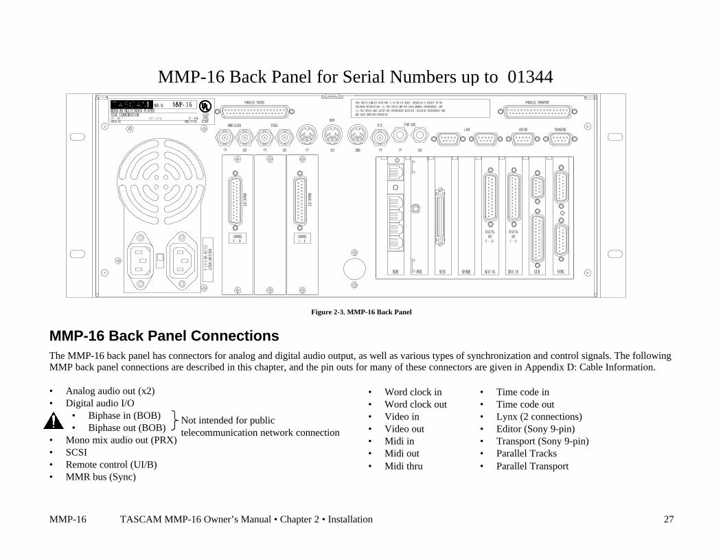
MMP-16 Back Panel Connections................................................................................................... 27
MMP-16 Back Panel Connections for Serial # 01345 and above ................................................... 28Audio Connections ...................................................................................................................................... 29
Analog Output Connections ..................................................................................................................... 29Digital Output Connections...................................................................................................................... 29Monitoring Connections........................................................................................................................... 29
Timecode and Video Reference Signals........................................................................................................ 30Video In/Out............................................................................................................................................ 30SMPTE/EBU Time Code In/Out .............................................................................................................. 30Biphase Connections................................................................................................................................ 31
Digital Audio Sample Reference Connections .............................................................................................. 31Word Clock ............................................................................................................................................. 31AES/EBU Sample Rate............................................................................................................................ 31
MIDI Connections ....................................................................................................................................... 32External Controllers & Bus Connections ...................................................................................................... 32
Lynx Bus / KCU Connection ................................................................................................................... 32MMR Sync Bus Connections ................................................................................................................... 32Serial Transport Connection..................................................................................................................... 33Serial Editor Connection .......................................................................................................................... 33Parallel Transport .................................................................................................................................... 33Parallel Tracks......................................................................................................................................... 33
Connecting External SCSI Media ................................................................................................... 34
SCSI Cables ..................................................................................................................................... 34Cable Quality............................................................................................................................................... 34Cable Length and Device Support ................................................................................................................ 34Cabling Wide and Narrow Devices in a System ............................................................................................ 35

MMP-16 TASCAM MMP-16 Owner’s Manual • Table of Contents 7
SCSI Termination............................................................................................................................ 35
Kingston Frame Configuration ....................................................................................................... 35
Wide SCSI Cards and Kingston Frames......................................................................................... 36Removing the Narrow Host Adapter (Symbios SYM 8600SP) ...................................................................... 36Installing the Wide Host Adapter (Symbios SYM8751SP) ............................................................................ 36Wide Kingston Drive Frames ....................................................................................................................... 37
Approved SCSI Drives .................................................................................................................... 37
DVD RAM Support ......................................................................................................................... 38
LIMDOW Optical Drives ................................................................................................................ 38
Remote Controllers for the TASCAM MMP-16............................................................................. 39
Keyboard Operation (with MM-RC option)................................................................................... 39Using the PC Keyboard................................................................................................................................ 40
Powering Up the System.................................................................................................................. 41
Verifying MMP-16 Installation ....................................................................................................... 41Software Updates......................................................................................................................................... 42
Factory Default Settings .................................................................................................................. 43
Chapter 3 MMP-16 Keys and Status Displays .................................................44MMP-16 Keys & Definitions ........................................................................................................... 44
MMP-16 Front Panel....................................................................................................................... 46
Front Panel Indicators, Switches, and Displays.............................................................................. 48LED Indicators ............................................................................................................................................ 48
Configuration Settings ............................................................................................................................. 48Active Mode/Key Indicators .................................................................................................................... 48Track Status and Metering ....................................................................................................................... 48Meter LEDs............................................................................................................................................. 49Machine Status LEDs .............................................................................................................................. 49
Liquid Crystal Display (LCD) ...................................................................................................................... 50Normal State Display ............................................................................................................................... 50Setup State Display.................................................................................................................................. 51View Track State Display......................................................................................................................... 51Slip Track State Display........................................................................................................................... 52Load Track State Display ......................................................................................................................... 52Backup State Display ............................................................................................................................... 53Verify State Display................................................................................................................................. 54Error State Display................................................................................................................................... 54
Front Panel Key Groups.................................................................................................................. 55Transport Group........................................................................................................................................... 55Setup and Wheel Group ............................................................................................................................... 56Wheel .......................................................................................................................................................... 57Track Group ................................................................................................................................................ 58Keypad Group ............................................................................................................................................. 62
Chapter 4 MMP-16 Operation ...........................................................................68Loading and Mounting Drives ........................................................................................................ 68
Loading a Project............................................................................................................................. 69
Loading Individual Tracks.............................................................................................................. 69Viewing Tracks............................................................................................................................................ 70
TASCAM MMP-16 Owner’s Manual • Table of Contents MMP-16 8
Unloading Tracks......................................................................................................................................... 70Deleting Tracks from the Disk...................................................................................................................... 70
Using the Backup Functions............................................................................................................ 70Backup ........................................................................................................................................................ 71Rename ....................................................................................................................................................... 71TapeMode Convert ...................................................................................................................................... 72Export.......................................................................................................................................................... 72
WaveFrame Export .................................................................................................................................. 72OMF Export ............................................................................................................................................ 73
To Import the OMF Export File into Pro Tools ............................................................................................. 73Crossfades in OMF ...................................................................................................................................... 73
Tape Mode Export to OMF...................................................................................................................... 74Pro Tools Export...................................................................................................................................... 74
Export As .................................................................................................................................................... 74Dynamic Backup Status Display................................................................................................................... 75
Using Registers ................................................................................................................................ 75Recalling Registers ...................................................................................................................................... 75Capturing the Current Time Code................................................................................................................. 75Trimming Time Code Values ....................................................................................................................... 76Using the Entry Register .............................................................................................................................. 76
Editing.............................................................................................................................................. 77
Local & Studio Monitoring ............................................................................................................. 82Headphone Volume (LEVEL) ...................................................................................................................... 82Headphone Jack (PHONES)......................................................................................................................... 82
The Lynx Bus................................................................................................................................... 82Transport Control......................................................................................................................................... 83Track Record Arm/Select (MMR-8 Only)..................................................................................................... 83Head/Tail..................................................................................................................................................... 83Slip Track/Region ........................................................................................................................................ 83Prev/Next..................................................................................................................................................... 83Undo/Redo................................................................................................................................................... 83Clear/Paste................................................................................................................................................... 84
The MMR Bus ................................................................................................................................. 85
Chapter 5 MMP-16 Setup Menus .....................................................................86The Setup State & the Setup Menus ............................................................................................... 86
Setup Operation............................................................................................................................... 87
Setup Menu Chart ........................................................................................................................... 88
000 Basic Setup ................................................................................................................................ 92000 Control Mode........................................................................................................................................ 92
Local/Bus ................................................................................................................................................ 92Time Code Chase..................................................................................................................................... 92Biphase Chase ......................................................................................................................................... 92Serial Transport ....................................................................................................................................... 93Editor ...................................................................................................................................................... 93Varispeed ................................................................................................................................................ 93
Serial Editor Port Details.............................................................................................................................. 93Record Ready Tallies............................................................................................................................... 93Sony P2 Chase and Offset Commands...................................................................................................... 93Serial Editor Port Active When Not ONLINE .......................................................................................... 93Automatic ONLINE................................................................................................................................. 93Local Machine Response to Serial Record Commands.............................................................................. 93
MMP-16 TASCAM MMP-16 Owner’s Manual • Table of Contents 9
Program Speed Play................................................................................................................................. 94Editor Mode Operation Without Video Reference..................................................................................... 94Hybrid Protocol on Serial Editor Port ....................................................................................................... 94
001 Frame Reference ................................................................................................................................... 94Automatic................................................................................................................................................ 94Video....................................................................................................................................................... 94
002 Sample Reference.................................................................................................................................. 94Automatic................................................................................................................................................ 94AES/EBU Input....................................................................................................................................... 94Ext Wordclock......................................................................................................................................... 95
003 Timecode Type...................................................................................................................................... 95004 Sample Rate .......................................................................................................................................... 95006 Varispeed Rate ...................................................................................................................................... 95
100 Bus Control ............................................................................................................................... 96100 Sync Group ........................................................................................................................................... 96110 MMR Bus Request ................................................................................................................................ 96111 Ident Request ........................................................................................................................................ 96112 Ident Assigned ...................................................................................................................................... 96120 Lynx Bus .............................................................................................................................................. 96121 Lynx Bus Address ................................................................................................................................. 96122 Lynx Bus V500 Mode ........................................................................................................................... 96
200 Transport .................................................................................................................................. 97210 Loop Mode............................................................................................................................................ 97211 Loop Record ......................................................................................................................................... 97212 Pre-roll.................................................................................................................................................. 97213 Post-roll ................................................................................................................................................ 97220 Next / Previous Mode ............................................................................................................................ 97221 Edit Sync Mode..................................................................................................................................... 97250 Slip Commit.......................................................................................................................................... 98
300 Biphase ...................................................................................................................................... 98300 Biphase Frame Rate............................................................................................................................... 98301 Biphase Pulse Rate ................................................................................................................................ 98302 Biphase Input ........................................................................................................................................ 98
400 Remote....................................................................................................................................... 98400 Editor Device ........................................................................................................................................ 98
TASCAM MMR-8................................................................................................................................... 99Sony PCM-7030 ...................................................................................................................................... 99Sony BVU-950 ........................................................................................................................................ 99
404 Editor Chase.......................................................................................................................................... 99420 MIDI Device ID .................................................................................................................................... 99
500 Audio ......................................................................................................................................... 99510 Crossfade .............................................................................................................................................. 99520 Meter Reference Level .......................................................................................................................... 99522 Clip LED on Play .................................................................................................................................. 99530 Reference Tone ..................................................................................................................................... 99550 Remote Meter Source .......................................................................................................................... 100
600 Digital I/O ............................................................................................................................... 100610 Digital Output Delay ........................................................................................................................... 100
700 Disk.......................................................................................................................................... 100710 Disk Initialize...................................................................................................................................... 100711 Disk Low Format ................................................................................................................................ 100720 Disk Cleanup ...................................................................................................................................... 100790 Drives Mounted................................................................................................................................... 101
800 Tracks/Project......................................................................................................................... 101
TASCAM MMP-16 Owner’s Manual • Table of Contents MMP-16 10
800 Project Name....................................................................................................................................... 101810 Track Prefix ........................................................................................................................................ 101
900 System ..................................................................................................................................... 101900 Store Settings ...................................................................................................................................... 101901 Recall Settings .................................................................................................................................... 101910 Set MM:DD:YY [Date] ....................................................................................................................... 101911 Set HH:MM:SS [Time] ....................................................................................................................... 102912 Change Password ................................................................................................................................ 102920 LED Brightness................................................................................................................................... 102940 Machine Name.................................................................................................................................... 102950 IP Address........................................................................................................................................... 102
Setting the IP Address............................................................................................................................ 102Format of IP Addresses.......................................................................................................................... 102
951 IP Net Mask ........................................................................................................................................ 102952 IP Gateway.......................................................................................................................................... 102Important Rules for IP Addresses ............................................................................................................... 103980 Serial Number ..................................................................................................................................... 103990 Software Version................................................................................................................................. 103995 Load Software..................................................................................................................................... 103
Chapter 6 File Format Support........................................................................105Show Project Format..................................................................................................................... 105
Show Track Format, Drive ID ...................................................................................................... 105
Formatting Macintosh Disks ......................................................................................................... 105
Delete and Disk Cleanup for Macintosh Volumes ........................................................................ 106
Macintosh File System Errors....................................................................................................... 106Macintosh Files Created by the MMR ........................................................................................................ 106
Support for Pro Tools® Session Files ........................................................................................... 107Pro Tools Features Supported..................................................................................................................... 108Pro Tools Features Not Supported .............................................................................................................. 108
Dynamic Voice Allocation..................................................................................................................... 108TDM Plug-Ins ....................................................................................................................................... 108Voice Output Assignments..................................................................................................................... 109
Restrictions When Using the Pro Tools Session Format .............................................................................. 109Pull Up / Pull Down............................................................................................................................... 109Frame and Sample Rates in Tape Mode.................................................................................................. 109Limitations on Number of Tracks........................................................................................................... 109Session Start Time Restrictions .............................................................................................................. 109Using TapeMode with ProTools Sessions............................................................................................... 110
Pro Tools Volume and Mute Automation ..................................................................................... 111Volume Automation................................................................................................................................... 111Mute Automation....................................................................................................................................... 111Disabling Pro Tools Volume Automation ................................................................................................... 112
Audio File Time Stamp Support ................................................................................................... 112
AIFF File Support ......................................................................................................................... 113
OMF Files ...................................................................................................................................... 113
Zaxcom DEVA Broadcast Wave File Support.............................................................................. 113DEVA Files Naming Conventions.............................................................................................................. 114
Akai DD-8 Support ........................................................................................................................ 114Playback .................................................................................................................................................... 114
MMP-16 TASCAM MMP-16 Owner’s Manual • Table of Contents 11
Export........................................................................................................................................................ 114
Editing File Formats not Written by The MM Series................................................................... 114
Sonic Solutions File Support ......................................................................................................... 115Using Sonic Lightspeed ............................................................................................................................. 115Sonic SSP, USP, and HD System Support .................................................................................................. 115Sonic Fade Files......................................................................................................................................... 115
Format Chart................................................................................................................................. 116
Chapter 7 MMP-16 System Applications .......................................................118Film Post Production ..................................................................................................................... 118
Biphase Setup Menus................................................................................................................................. 119MMP-16 Film Connections ........................................................................................................................ 120
Video Post Production ................................................................................................................... 120The Lynx Bus ............................................................................................................................................ 120
Chapter 8 Maintenance & Service ..................................................................121MMP Output Level Calibrations................................................................................................................. 121MOC Calibration Procedure ....................................................................................................................... 121
Adding External Drives to the System .......................................................................................... 122
Formatting Disks ........................................................................................................................... 123
Using Removable Media................................................................................................................ 123
Chapter 9 Technical Support ..........................................................................124MMP-16 System Software............................................................................................................. 124
Appendix A: Control Panel Command Summary........................................................................ 125Transport Group .................................................................................................................................... 125Setup and Wheel Group ......................................................................................................................... 125Keypad keys .......................................................................................................................................... 126Track Select Keys .................................................................................................................................. 128
Appendix B: TASCAM MMP-16 Drive Compatibility Chart.......................... 129Approved SCSI Drives............................................................................................................................... 129
Appendix C: WaveFrame Compatibility ...................................................................................... 131
Appendix D: MMP-16 Cable Information.................................................................................... 133Parallel Tracks and Parallel Transport Connector Pinout............................................................................. 133MIDI IN/THRU/OUT Connector pinout..................................................................................................... 134LYNX (Remote Controller) Connector pinout ............................................................................................ 134EDITOR Connector pinout......................................................................................................................... 134TRANSPORT (Sony 9-pin) Connector pinout ............................................................................................ 135ANALOG OUTPUT Connectors pinouts.................................................................................................... 136BIPH (Biphase) Connectors pinout............................................................................................................. 136DO (AES/EBU Digital Audio Out 1-8) Connector pinout ........................................................................... 137AO (AES/EBU Digital Audio Out 9-16) Connector pinout ......................................................................... 137SYNC (MMR-Bus) Connector pinout ........................................................................................................ 138TIMECODE IN Connector......................................................................................................................... 138TIMECODE OUT Connector..................................................................................................................... 138WORD CLOCK IN Connector................................................................................................................... 139WORD CLOCK OUT Connector ............................................................................................................... 139VIDEO IN/OUT Connector........................................................................................................................ 139SERIAL CONNECTORS .......................................................................................................................... 139SCSI Connector ......................................................................................................................................... 139PRX Connector.......................................................................................................................................... 139
TASCAM MMP-16 Owner’s Manual • Table of Contents MMP-16 12
Keyboard Operation (with optional MM-RC) ............................................................................................. 140The MM-RC Keyboard Connector ............................................................................................................. 140
Appendix E: MMP-16 Glossary .................................................................................................... 141
Appendix F: Disk Time Chart....................................................................................................... 147
Appendix G: Macintosh File System Error Messages .................................................................. 148Macintosh File System Error Codes............................................................................................................ 149
Appendix H: MMR/MMP MIDI Machine Control Protocol ....................................................... 154MMC Information Fields ........................................................................................................................... 154MMR-8 MMC Signature............................................................................................................................ 155MMP-16 MMC Signature .......................................................................................................................... 156MIDI Inquiry Message ............................................................................................................................... 156
Index .............................................................................................................................................. 157
MMP-16 Owner’s Manual Version 4.1 TRAINING
TASCAM MMP-16 Owner’s Manual • Chapter 1 • General Information MMP-16 13
-12
-25
SLIP
12
LINEON
PASTE
4
EDIT MON
1EVENT
2 3
COPY
9CUT
10
-6
SLIP
-25
-12
0 0
-12
-6
-25
SLIP
11CLEAR
-12
-6
-25
SLIP
0
TRACK
5
VIEWLOADTRACK
6DELETE
7UNLOAD
13INSERT
0
-6
0
-12
-6
-25
SLIP
14OPEN
15UNDO
0
-12
-6
-25
SLIP
0
-12
-6
-25
SLIP
SLIPTRACK
8BACKUP
0
LYNX SYNC
CAPT
INTERLOCK
16REDO
-25
-12
-6
0
SLIP
ERROR
LOCK
BUSY
OFFSET
TIME
CLR
CANCEL
MMP-16
+12
MAX
CLIP
TASCAM2
MAX
+12
+6
CLIP
1
+6
+12
MAX
CLIP
3
+6
+12
MAX
CLIP
54 6 7 11
+6
8 9
+6
+12
MAX
CLIP
10
+6
+12
MAX
CLIP
12
+6
+12
MAX
CLIP
13 14 16
+6
CLIP
15
+12
MAXTONE
MIDI
SER TRAN
EDITOR
MAST
VARI
SLAVE
TC/FEET
SHTL
LOC
STO=
SHIFT
YES
RCL
NO
LOOP
1 2
OFST
4RDR
5
3
FREE
6
OUT
IN
7TAIL
HEAD
8 9PREV EDIT
NEXT EDIT
TRIM JOG
P. DOWN
NON STD.
TRIM
SETUP
+/-
TIME CODE
NDF
29.97
25
24
DF
RATE
44.100
48.000
P. UP
-
SUBF
+
EXT RSLV
SYNC GRP
1
3
4
2 MMR
REMOVABLE
HARD DRIVE
LYNX
IDENT
LOCAL/BUS
BIPH TRAN
BIPH CHASE
TC CHASE
CONTROLREFERENCE
WORD
SAMPLE
MMR
AES
INT
FRAME
BIPH
LYNX
VIDEO
TC
MODE
POWER
PHONES
MOUNT
UNMOUNT
Chapter 1 General InformationThis chapter presents the main features and capabilities of the MMP-16 hardware and a functionaloverview of its Panel/Display states. MMP-16 product specifications are also included.
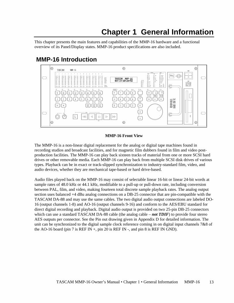
MMP-16 Introduction
MMP-16 Front View
The MMP-16 is a non-linear digital replacement for the analog or digital tape machines found inrecording studios and broadcast facilities, and for magnetic film dubbers found in film and video post-production facilities. The MMP-16 can play back sixteen tracks of material from one or more SCSI harddrives or other removable media. Each MMP-16 can play back from multiple SCSI disk drives of varioustypes. Playback can be in exact or track-slipped synchronization to industry-standard film, video, andaudio devices, whether they are mechanical tape-based or hard drive-based.
Audio files played back on the MMP-16 may consist of selectable linear 16-bit or linear 24-bit words atsample rates of 48.0 kHz or 44.1 kHz, modifiable to a pull-up or pull-down rate, including conversionbetween PAL, film, and video, making fourteen total discrete sample playback rates. The analog outputsection uses balanced +4 dBu analog connections on a DB-25 connector that are pin-compatible with theTASCAM DA-88 and may use the same cables. The two digital audio output connections are labeled DO-16 (output channels 1-8) and AO-16 (output channels 9-16) and conform to the AES/EBU standard fordirect digital recording and playback. Digital audio output is provided on two 25-pin DB-25 connectorswhich can use a standard TASCAM DA-88 cable (the analog cable – not TDIF) to provide four stereoAES outputs per connector. See the Pin out drawing given in Appendix D for detailed information. Theunit can be synchronized to the digital sample clock reference coming in on digital input channels 7&8 ofthe AO-16 board (pin 7 is REF IN +, pin 20 is REF IN -, and pin 8 is REF IN GND).

MMP-16 TASCAM MMP-16 Owner’s Manual • Chapter 1 • General Information14
The MMP-16 will directly play back material created on many different digital audio workstationsystems. A format compatibility chart is given in the Functional Specifications section of this chapter.The disk drive or drives containing edited Project (EDL and audio) files may be simply “unplugged” fromthe workstation and then “hot-plugged” into the MMP-16, using the standard internal Kingston hard drivecarrier, or otherwise connected to the MMP-16’s external SCSI port. Optionally, files on a RAID may beaccessed via the external SCSI port as well. Once the drive(s) are mounted by the MMP-16, tracks fromone or more projects may be loaded as required for the mix session. Sound files of the same or differentaudio file formats may be played back on the same unit simultaneously from one or more drives.
When the MMP-16 is turned on for the first time, the system default operating parameters are loaded, andthe machine boots into the Normal state (see the Functional Overview section in this chapter). There areten user settings files that may be stored to and recalled from the internal hard drive so that the MMP-16setup parameters can be instantly reconfigured between mix sessions. The MMP-16’s operatingparameters can be manually changed at any time via Setup menu selections. Password protection may beused to prevent some parameters from being changed inadvertently.
Hardware OverviewThe MMP-16 comes standard with one removable Kingston drive carrier. The Kingston carrier can hold astandard SCSI drive for playback of audio tracks. An internal IDE hard drive holds the operating system,the MMP-16 software, and the parameter settings files. Additional external SCSI drives can be connectedand accessed by the MMP-16. This allows loading tracks simultaneously from more than one disk. A listof approved media drives is given in Appendix B.
The MMP-16 is based on a standard Intel Pentium™ processor-based PC motherboard, withintegral PCI and ISA bus slots running under an industry-standard operating system. The MMP-16
processing and interface boards plug directly into this PC motherboard. There is a Lithium battery #CR2032 for the CMOS circuit on the motherboard. Caution: Battery May Explode if Mistreated. DoNot Recharge, Disassemble, or Dispose of in Fire. The MOC (digital-to-analog Output Converter)boards are in their own shielded cage, connected to the AO-16 (Analog Output) card via ribbon cables.Very high quality 20-bit converters on all analog outputs assure excellent audio fidelity. The MMP-16uses 24-bit internal digital resolution for all digital audio processing. The MMP-16 plays back audiostored in standard linear 16-bit or 24-bit sound files.
Internal Boards for Units with Serial Numbers up to 01344
The PRX (DSP) card performs the audio processing for the MMP-16. A standard Symbios SCSI-2controller card also plugs into the PCI bus. The Sync card, the UI/B (User Interface/Biphase) card, theAO-16 (Analog Output) card, and the DO-16 (AES/EBU Digital Output) card are all plugged into the ISAbus. The Biphase Operations Board (BOB) occupies a slot on the back panel to provide connections forthe system’s four Biphase inputs and one Biphase throghpu. It is attached to the UI/B card via a ribboncable and is not plugged into a slot.
Internal Boards for Units with Serial Numbers of 01345 and above
Units with serial numbers of 01609 and above have a different set of internal processing boards.Functionally, these units are identical to previous units. The change was made to facilitate a morestreamlined manufacturing process. Instead of separate boards for DSP processing, sync, remote control,etc., these functions have been combined into a single board designated as the M2 board. Connectors onthe side of the M2 board have ribbon cables attached which break out to brackets and connectors servingthe same functions as the previous array of boards and connectors.
TASCAM MMP-16 Owner’s Manual • Chapter 1 • General Information MMP-16 15
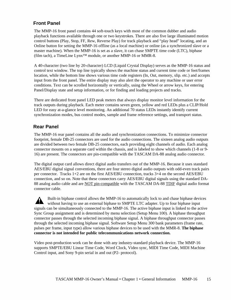
Front Panel
The MMP-16 front panel contains 44 soft-touch keys with most of the common dubber and audioplayback functions available through one or two keystrokes. There are also five large illuminated motioncontrol buttons (Play, Stop, FF, Rew, Reverse Play) for track playback and “play head” locating, and anOnline button for setting the MMP-16 offline (as a local machine) or online (as a synchronized slave or amaster machine). When the MMP-16 is set as a slave, it can chase SMPTE time code (LTC), biphase(film tach), a TimeLine Lynx™ module, or another MMP-16 or MMR-8.
A 40-character (two line by 20-character) LCD (Liquid Crystal Display) serves as the MMP-16 status andcontrol text window. The top line typically shows the machine status and current time code or feet/frameslocation, while the bottom line shows various time code registers (In, Out, memory, slip. etc.) and acceptsinput from the front panel. The entire display may also alert the operator to any machine or user errorconditions. Text can be scrolled horizontally or vertically, using the Wheel or arrow keys, for enteringPanel/Display state and setup information, or for finding and loading projects and tracks.
There are dedicated front panel LED peak meters that always display monitor level information for thetrack outputs during playback. Each meter contains seven green, yellow and red LEDs plus a CLIP/HoldLED for easy at-a-glance level monitoring. An additional 70 status LEDs instantly identify currentsynchronization modes, bus control modes, sample and frame reference settings, and transport status.
Rear Panel
The MMP-16 rear panel contains all the audio and synchronization connections. To minimize connectorfootprint, female DB-25 connectors are used for the audio connections. The sixteen analog audio outputsare divided between two female DB-25 connectors, each providing eight channels of audio. Each analogconnector mounts on a separate card within the chassis, and is labeled to show which channels (1-8 or 9-16) are present. The connectors are pin-compatible with the TASCAM DA-88 analog audio connector.
The digital output card allows direct digital audio transfers out of the MMP-16. Because it uses standardAES/EBU digital signal conventions, there are four stereo digital audio outputs with odd-even track pairsper connector. Tracks 1+2 are on the first AES/EBU connection, tracks 3+4 on the second AES/EBUconnection, and so on. Note that these connectors carry AES/EBU digital signals using the standard DA-88 analog audio cable and are NOT pin-compatible with the TASCAM DA-88 TDIF digital audio formatconnector cable.
Built-in biphase control allows the MMP-16 to automatically lock to and chase biphase deviceswithout having to use an external biphase to SMPTE LTC adapter. Up to four biphase input
signals can be simultaneously connected to the MMP-16. The active biphase input is linked to the activeSync Group assignment and is determined by menu selection (Setup Menu 100). A biphase throughputconnector passes through the selected incoming biphase signal. A biphase throughput connector passesthrough the selected incoming biphase signal. Software Setup Menu 300 bank parameters (frame rate,pulses per frame, input type) allow various biphase devices to be used with the MMR-8. The biphaseconnector is not intended for public telecommunications network connection.
Video post-production work can be done with any industry-standard playback device. The MMP-16supports SMPTE/EBU Linear Time Code, Word Clock, Video sync, MIDI Time Code, MIDI MachineControl input, and Sony 9-pin serial in and out (P2- protocol).
MMP-16 TASCAM MMP-16 Owner’s Manual • Chapter 1 • General Information16
Accessory Products
The TASCAM MM-RC is a dedicated remote control unit designed specially for use with the MMR-8recorder and the MMP-16 player. It connects directly to the UI/B board on the MMR/MMP back paneland allows control of any combination of up to 100 MMR-8 or MMP-16 units.
The TASCAM MMU-16 is a multi-segment digital meter unit which can display sixteen channels ofaudio level information. Two connectors on the back of the MMU-16 allow it to be connected to one ortwo MMR-8 units, or an MMP-16 sixteen channel player. The MMU-16 can also be connected to theMM-RC for displaying detailed level information for the MMR-8 or MMP-16 unit being accessed by theMM-RC. The MMU-16 comes with standard rack ears for mounting in a standard 19” equipment rackand also with mounting brackets for attaching the unit to an MM-RC.
The TimeLine Lynx Keyboard Control Unit (KCU) can function directly as a remote controller for up tosix MMP-16s without the use of dedicated Lynx-2 modules, since the MMP-16 contains the functionalequivalent of an integrated Lynx-2 synchronizer. Optionally, Lynx-2 modules can also be connected tothe Lynx port of the MMP so that other transports connected to the Lynx bus may also be controlled froma Lynx KCU connected to the MMP-16. TimeLine offers a special software version for the Lynx KCU(KCU 900 software) which includes special MMP support for some editing and event slip commands.Other remote controllers can also be used for controlling the transport functions of the MMP-16 throughthe Parallel Transport connector or via Sony P2 protocol through the 9-pin serial Editor port.
TASCAM MMP-16 Owner’s Manual • Chapter 1 • General Information MMP-16 17
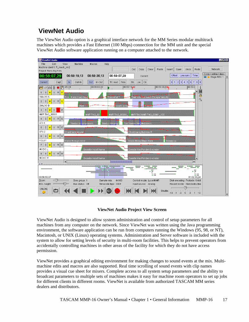
ViewNet AudioThe ViewNet Audio option is a graphical interface network for the MM Series modular multitrackmachines which provides a Fast Ethernet (100 Mbps) connection for the MM unit and the specialViewNet Audio software application running on a computer attached to the network.
ViewNet Audio Project View Screen
ViewNet Audio is designed to allow system administration and control of setup parameters for allmachines from any computer on the network. Since ViewNet was written using the Java programmingenvironment, the software application can be run from computers running the Windows (95, 98, or NT),Macintosh, or UNIX (Linux) operating systems. Administration and Server software is included with thesystem to allow for setting levels of security in multi-room facilities. This helps to prevent operators fromaccidentally controlling machines in other areas of the facility for which they do not have accesspermission.
ViewNet provides a graphical editing environment for making changes to sound events at the mix. Multi-machine edits and macros are also supported. Real time scrolling of sound events with clip namesprovides a visual cue sheet for mixers. Complete access to all system setup parameters and the ability tobroadcast parameters to multiple sets of machines makes it easy for machine room operators to set up jobsfor different clients in different rooms. ViewNet is available from authorized TASCAM MM seriesdealers and distributors.

MMP-16 TASCAM MMP-16 Owner’s Manual • Chapter 1 • General Information18
Functional OverviewThe MMP-16 operates in any of eight different Panel/Display states (simply referred to as “states” forconvenience). These states are distinguished by the nature of the information displayed in the LCDwindow and by which keys are functionally available while in that state. These MMP-16 Panel/Displaystates are described here.
Normal state is the default Panel/Display state on power-up. In this state, the LCD shows the currentsystem play time in the top of the display, and shows the active register (last requested register or functiontime) in the bottom of the display. All keys are active while in this state, and will respond by performingan action, accessing a register, or changing to the state written on the key. Shifted key functions are alsoavailable by first pressing the SHIFT key, then pressing the key which corresponds to the desired shiftedfunction. Once the SHIFT key is selected, pressing the appropriate key to activate the desired shiftedfunction completes the SHIFT operation. The SHIFT state can be cancelled by pressing SHIFT again, orby pressing CLR, to return the system to normal key selection.
Pressing the SETUP key activates the Setup state. This state gives access to the system setup menus,where most of the operating parameters of the MMP-16 can be altered. Some parameters are changeableonly under certain operating conditions (while stopped, etc.), although all are viewable at any time in theSetup state. Once in the Setup state, you may return to the Normal state by pressing the SETUP keyagain, or by pressing CLR.
There are three types of Panel/Display states that deal with MMP-16 track operations. These are LoadTrack, View Track, and Slip Track. Pressing the LOAD TRACK, TRACK, or SLIP keys puts theMMP-16 into one of these Track states. The SEL keys for each MMP track are used in conjunction withthese keys to identify the specific track to be loaded, viewed, or slipped.
There are also two keys to the left of the Track state keys labeled EDIT and MON. These keys do notchange the state of the MMP display, but are used to determine what status is being indicated for eachMMP track by the track selection LEDs when the SEL keys are pressed while in the Normal state ofoperation. One of these keys is always active as the current Track Mode. Since these keys function alongwith the Track state keys to identify the function being specified by the SEL keys, the entire group of fivekeys (EDIT, MON, LOAD TRACK, TRACK, and SLIP) are also referred to as the Track Mode keys.
The Track states supersede the Normal state since they change the display and make certain keysunavailable until the Track state is exited or cleared. To exit a Track state and return the MMP-16 to theNormal state, it is necessary to either complete the selected track operation (by pressing STO to load aProject, for example), or press the selected Track state key again, or press the CLR key to cancel theoperation. After exiting a Track state, the system will return to the Normal state and the last selectedTrack Mode (EDIT, MON).
Pressing the LOAD TRACK key activates the Load Track state. This state allows for loadingWaveFrame projects, OMF Compositions, or Pro Tools Session files from any mounted disk volume.This state also allows loading of individual tracks from a Project, Composition, or Session (hence thename of this key and state), and moving of tracks from one MMP channel to another. The shifted functionof LOAD TRACK allows for deleting WaveFrame Projects or Tracks. The MMP-16 software does notcurrently allow OMF Compositions and Pro Tools Session Files to be deleted.

TASCAM MMP-16 Owner’s Manual • Chapter 1 • General Information MMP-16 19
The MMP Backup state is accessed via the Load Track state by pressing SHIFT+SLIP after choosing(scrolling to) the desired Project while in the LOAD TRACK state. This state is similar to the Setup statein that it has menu choices which are accessed by using the Up/Down arrow keys or the Wheel. The keychoices available in the Backup state are the same as those in the Setup state, hence it exists at the samelevel of the hierarchy of panel/display states as the Setup state.
Pressing the TRACK key activates the View Track state. This state allows for viewing the names ofloaded tracks, and unloading of tracks (the shifted function of the TRACK key) from the loaded track list.
Pressing the SLIP key activates the Slip Track state. This state allows for slipping one or more of thealready loaded tracks in time.
Verify state supersedes the Normal and Track states. The two most common Verify state functions areconfirmation (a Yes/No answer is required from the user) and password entry (a password must beentered to complete the action request). Both of these requests override most other actions or do not allowaccess to the Normal, Setup, or Track states until they are cleared or a valid response is entered. Verifystate, when cleared, usually drops the MMP-16 back into the previously active state.
Error state is the final level in the hierarchy of Panel/Display states. In this state, the ERROR status lightflashes and the user is asked to clear a condition by pressing the CLR key, or if that is impossible (as inthe case of a fatal error), to note the error information and possibly take some extraordinary action (suchas re-starting the MMP-16). Until the Error state is cleared, or a valid response is entered, access to theNormal, Setup, or Track states is not allowed. The Error state, when cleared, may drop to another state, orto any appropriate condition—depending on the type and severity of the error.
These states are hierarchical in the sense that some require a response or they require a state to be clearedbefore certain keys or other states can be accessed. The Normal state is at the base of the hierarchybecause it is the default on startup and can always be accessed from any other state or by pressing theCLR key as many times as is necessary to clear any other state. The transport keys can be accesseddirectly from any state, so the MMP can always playback, regardless of what other functions or states arebeing accessed. The following diagram illustrates the hierarchical relationship between the various states,based on the number of choices available from each state.
MMP-16 TASCAM MMP-16 Owner’s Manual • Chapter 1 • General Information20
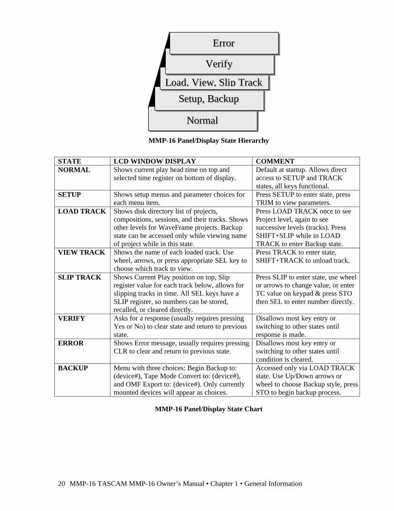
MMP-16 Panel/Display State Hierarchy
STATE LCD WINDOW DISPLAY COMMENTNORMAL Shows current play head time on top and
selected time register on bottom of display.Default at startup. Allows directaccess to SETUP and TRACKstates, all keys functional.
SETUP Shows setup menus and parameter choices foreach menu item.
Press SETUP to enter state, pressTRIM to view parameters.
LOAD TRACK Shows disk directory list of projects,compositions, sessions, and their tracks. Showsother levels for WaveFrame projects. Backupstate can be accessed only while viewing nameof project while in this state.
Press LOAD TRACK once to seeProject level, again to seesuccessive levels (tracks). PressSHIFT+SLIP while in LOADTRACK to enter Backup state.
VIEW TRACK Shows the name of each loaded track. Usewheel, arrows, or press appropriate SEL key tochoose which track to view.
Press TRACK to enter state,SHIFT+TRACK to unload track.
SLIP TRACK Shows Current Play position on top, Slipregister value for each track below, allows forslipping tracks in time. All SEL keys have aSLIP register, so numbers can be stored,recalled, or cleared directly.
Press SLIP to enter state, use wheelor arrows to change value, or enterTC value on keypad & press STOthen SEL to enter number directly.
VERIFY Asks for a response (usually requires pressingYes or No) to clear state and return to previousstate.
Disallows most key entry orswitching to other states untilresponse is made.
ERROR Shows Error message, usually requires pressingCLR to clear and return to previous state.
Disallows most key entry orswitching to other states untilcondition is cleared.
BACKUP Menu with three choices: Begin Backup to:(device#), Tape Mode Convert to: (device#),and OMF Export to: (device#). Only currentlymounted devices will appear as choices.
Accessed only via LOAD TRACKstate. Use Up/Down arrows orwheel to choose Backup style, pressSTO to begin backup process.
MMP-16 Panel/Display State Chart
NNNooorrrmmmaaalll
SSSeeetttuuuppp,,, BBBaaaccckkkuuuppp
LLLoooaaaddd,,, VVViiieeewww,,, SSSllliiippp TTTrrraaaccckkk
VVVeeerrriiifffyyy
EEErrrrrrooorrr
TASCAM MMP-16 Owner’s Manual • Chapter 1 • General Information MMP-16 21
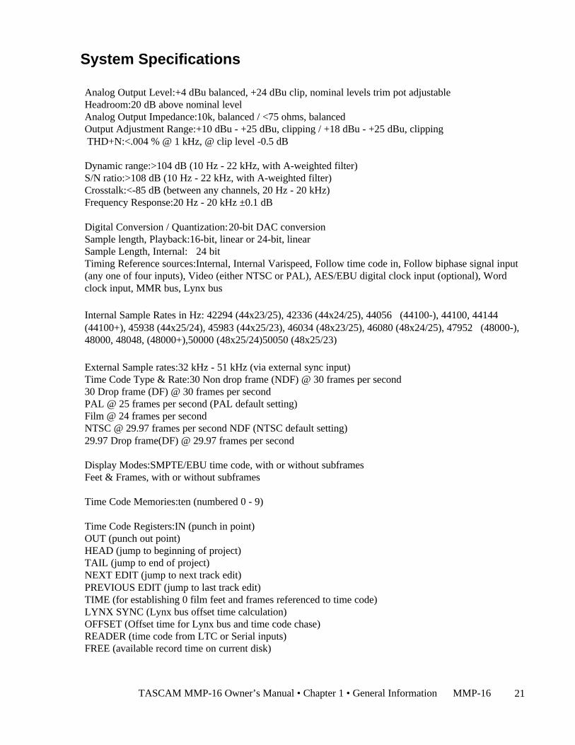
System Specifications
Analog Output Level:+4 dBu balanced, +24 dBu clip, nominal levels trim pot adjustableHeadroom:20 dB above nominal levelAnalog Output Impedance:10k, balanced / <75 ohms, balancedOutput Adjustment Range:+10 dBu - +25 dBu, clipping / +18 dBu - +25 dBu, clipping THD+N:<.004 % @ 1 kHz, @ clip level -0.5 dB
Dynamic range:>104 dB (10 Hz - 22 kHz, with A-weighted filter)S/N ratio:>108 dB (10 Hz - 22 kHz, with A-weighted filter)Crosstalk:<-85 dB (between any channels, 20 Hz - 20 kHz)Frequency Response:20 Hz - 20 kHz ±0.1 dB
Digital Conversion / Quantization:20-bit DAC conversionSample length, Playback:16-bit, linear or 24-bit, linearSample Length, Internal: 24 bitTiming Reference sources:Internal, Internal Varispeed, Follow time code in, Follow biphase signal input(any one of four inputs), Video (either NTSC or PAL), AES/EBU digital clock input (optional), Wordclock input, MMR bus, Lynx bus
Internal Sample Rates in Hz: 42294 (44x23/25), 42336 (44x24/25), 44056 (44100-), 44100, 44144(44100+), 45938 (44x25/24), 45983 (44x25/23), 46034 (48x23/25), 46080 (48x24/25), 47952 (48000-),48000, 48048, (48000+),50000 (48x25/24)50050 (48x25/23)
External Sample rates:32 kHz - 51 kHz (via external sync input)Time Code Type & Rate:30 Non drop frame (NDF) @ 30 frames per second30 Drop frame (DF) @ 30 frames per secondPAL @ 25 frames per second (PAL default setting)Film @ 24 frames per secondNTSC @ 29.97 frames per second NDF (NTSC default setting)29.97 Drop frame(DF) @ 29.97 frames per second
Display Modes:SMPTE/EBU time code, with or without subframesFeet & Frames, with or without subframes
Time Code Memories:ten (numbered 0 - 9)
Time Code Registers:IN (punch in point)OUT (punch out point)HEAD (jump to beginning of project)TAIL (jump to end of project)NEXT EDIT (jump to next track edit)PREVIOUS EDIT (jump to last track edit)TIME (for establishing 0 film feet and frames referenced to time code)LYNX SYNC (Lynx bus offset time calculation)OFFSET (Offset time for Lynx bus and time code chase)READER (time code from LTC or Serial inputs)FREE (available record time on current disk)
MMP-16 TASCAM MMP-16 Owner’s Manual • Chapter 1 • General Information22
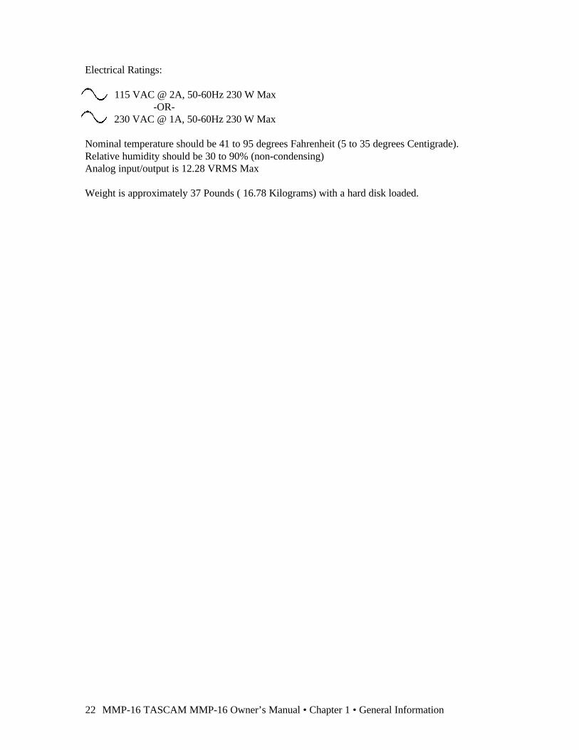
Electrical Ratings:
115 VAC @ 2A, 50-60Hz 230 W Max-OR-
230 VAC @ 1A, 50-60Hz 230 W Max
Nominal temperature should be 41 to 95 degrees Fahrenheit (5 to 35 degrees Centigrade).Relative humidity should be 30 to 90% (non-condensing)Analog input/output is 12.28 VRMS Max
Weight is approximately 37 Pounds ( 16.78 Kilograms) with a hard disk loaded.
MMP-16 TASCAM MMP-16 Owner’s Manual • Chapter 2 • Installation 23
Chapter 2 InstallationThis chapter covers the physical installation of the TASCAM MMP-16 as either a stand-alonerecording/playback system or as part of a larger, multiple unit digital dubber system. Descriptions aregiven of the various connectors on the MMP back panel. Both general installation procedures and specificapplication installations are covered.
MMP-16 Materials Kit BoxBefore connecting the MMP-16 hardware to your audio system and to your video or film playbackdevices, verify that you have all the equipment required to complete the task. The following equipment isincluded in the MMP Materials Kit Box:
Rack Ears Kit For rack mount installation, the two rack ears may be attached to the front sides ofthe MMP-16 chassis using the six 8-32 x 3/8” Phillips head screws included in theMMP-16 materials kit. The MMP-16 can be used without the rack ears for desktopapplications.
MMR Bus A three-foot sync cable for synchronizing the operation of multiple MMP-Sync Cable 16’s together via the rear panel MMR bus connectors.
RS422 Cable A 9-pin RS-422 (232) cable for attaching the COM port to a terminal for runningfield diagnostics. Also may be used for 9-pin serial connections.
Kingston One Kingston removable drive carrier is included with the system. ThisRemovable carrier allows drives to be hot-swapped while the system is powered on. ItSCSI Drive is necessary to install a SCSI drive from the list of approved drives into theCarrier Instructions Kingston carrier before you can playback audio using the carrier with the MMP-16.
The instruction manual for installing drives in the Kingston carrier is in the MMP-16 materials kit.
AC Power Cord A six-foot (1.83 Meter) IEC AC Mains cord set is included with the MMR-8. Themains connector for 115 VAC systems is USA standard. A six-foot (1.83 Meter)AC Mains cord set for use in Europe, proper for the country of use will be suppliedby your TASCAM dealer. Attach the AC connector in accordance with localrequirements.
Toolkit As a convenience, a small tool kit consisting of a “tweaker” and a smallscrewdriver is included in the zip-locked plastic bag in the materials kit. The“tweaker” may be used for making any necessary adjustments to the analog trimpots on the analog audio output board.
24 TASCAM MMP-16 User’s Guide • Chapter 2 • Installation MMP-16
General Guidelines
Mounting Rack Ears
The MMP-16 is a self-contained sixteen channel digital playback device designed to be mounted in astandard 19” (48.26 cm) IEC equipment rack in either the mix studio or a dedicated machine room in aprofessional audio recording facility. As such, each MMP-16 is housed in a steel chassis 19-inches (48.26cm) wide by 17 ¼ inches (43.81 cm) deep by 7-inches (17.78 cm) tall. Each MMR-8 requires 5U (7-inches or 17.78 cm) of rack space.
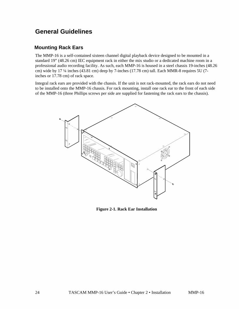
Integral rack ears are provided with the chassis. If the unit is not rack-mounted, the rack ears do not needto be installed onto the MMP-16 chassis. For rack mounting, install one rack ear to the front of each sideof the MMP-16 (three Phillips screws per side are supplied for fastening the rack ears to the chassis).
Figure 2-1. Rack Ear Installation
MMP-16 TASCAM MMP-16 Owner’s Manual • Chapter 2 • Installation 25
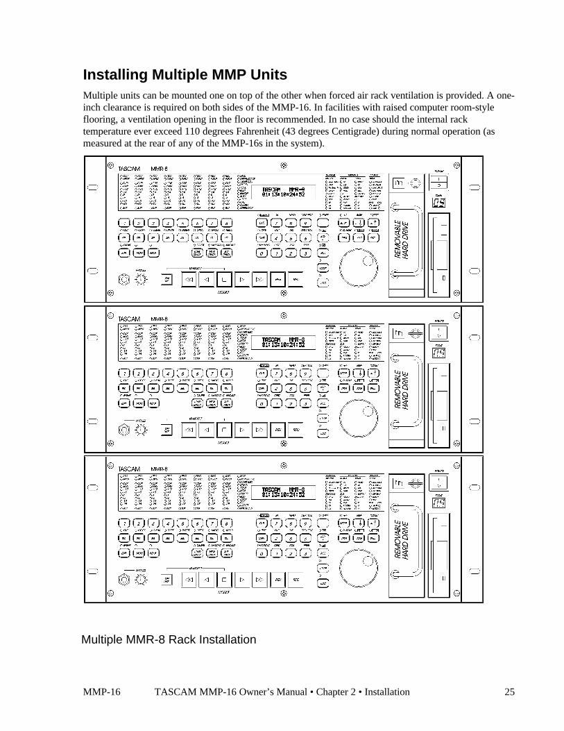
Installing Multiple MMP UnitsMultiple units can be mounted one on top of the other when forced air rack ventilation is provided. A one-inch clearance is required on both sides of the MMP-16. In facilities with raised computer room-styleflooring, a ventilation opening in the floor is recommended. In no case should the internal racktemperature ever exceed 110 degrees Fahrenheit (43 degrees Centigrade) during normal operation (asmeasured at the rear of any of the MMP-16s in the system).
Multiple MMR-8 Rack Installation

26 TASCAM MMP-16 User’s Guide • Chapter 2 • Installation MMP-16
AC Mains and Grounding (Earthing) Considerations
Each MMP-16 requires one AC mains connection. A standard six-foot (1.83 Meter) power cord set isincluded with each MMP-16 wired for the USA standard. A six-foot (1.83 Meter) AC Mains cord set foruse in Europe, proper for the country of use will be supplied by your TASCAM dealer. The AC mainsoutlet must be capable of delivering 230 watts (2 amps) for each MMP-16 in the system. The main powersupply has a 115/230 VAC switch on the back of the unit. This switch should be set to match the facilitypower level.
An unswitched female IEC convenience outlet is located on the rear panel of each MMP-16. In normaluse there is no connection to this outlet, although other electronics equipment using IEC plugs, anddrawing less than 120 watts total, can be connected to this outlet using the appropriate male-to-femaleIEC power cord (like those used with computer monitors).
A facility-wide UPS system is recommended for protecting the MMP-16, and all your audio equipment,from power line spikes, surges, brownouts, and line failure. If a facility-wide UPS is not available, eachMMP-16 should be connected to a home computer-type surge/spike protection system (of 250 wattsminimum) which is then plugged into an isolated ground AC outlet.
Caution: Grounding (Earthing)
Do not defeat the AC cord U-ground as this will present a potentially dangerous operatorhazard. Using an isolated ground outlet ensures the proper chassis grounding to themains “power company” ground. Using only isolated ground outlets throughout a facilitywill prevent audio ground loops caused by AC outlets with different ground potentials. AGround Stud is provided on the back panel for chassis grounding of the MMP-16.
Audio Cables
Analog Output All analog output on the MMP-16 is done through a pair of 25-pinD-sub connectors which are pin-compatible with the TASCAM DA-88 connector.TASCAM DA-88 DB-25 to XLR cables, with either male (output) or female(input) XLR connectors, are available from your authorized TASCAM dealer.
Digital Output DA-88 analog output cables should be used as digital out cables (NOT TDIFcables). This arrangement provides four stereo AES/EBU digital outputs on eachDA-88 cable, for a total of 16 channels of digital audio output.
MMP-16 TASCAM MMP-16 Owner’s Manual • Chapter 2 • Installation 27
OUT
MIDI
115/230 VAC 1/0.5 AAUXILIARY OUTLET
9 - 16CHANNEL
ANALOG OUT
1 - 8CHANNEL
ANALOG OUT
MMP-16
TEAC CORPORATIONSERIAL NO.115 / 230 ~, 2.0 / 1.0 A,
MODULAR MULTITRACK PLAYERMODEL NO.
PARALLEL TRACKS
50 - 60HzMADE IN USA
XXDK
E1XXXXUL1950
IN OUT
WORD CLOCK
R
LISTED
IN OUT
VIDEO
IN
BOB SCSIPRX SPARE DIO 16AIO 16 UIB SYNC
THIS DEVICE COMPLIES WITH PART 15 OF THE FCC RULES. OPERATION IS SUBJECT TO THEFOLLOWING RESTRICTIONS: (1) THIS DEVICE MAY NOT CAUSE HARMFUL INTERFERENCE, AND(2) THIS DEVICE MUST ACCEPT ANY INTERFERENCE RECEIVED, INCLUDING INTERFERENCE THAT
TIME CODE
MAY CAUSE UNDESIRED OPERATION.
THRU IN IN
VITC
OUT
LYNX
PARALLEL TRANSPORT
EDITOR TRANSPORT
1 - 8OUT
DIGITALOUT
DIGITAL
9 - 16
Figure 2-3. MMP-16 Back Panel
MMP-16 Back Panel ConnectionsThe MMP-16 back panel has connectors for analog and digital audio output, as well as various types of synchronization and control signals. The followingMMP back panel connections are described in this chapter, and the pin outs for many of these connectors are given in Appendix D: Cable Information.
• Analog audio out (x2)• Digital audio I/O
• Biphase in (BOB)• Biphase out (BOB)
• Mono mix audio out (PRX)• SCSI• Remote control (UI/B)• MMR bus (Sync)
Not intended for publictelecommunication network connection
• Word clock in• Word clock out• Video in• Video out• Midi in• Midi out• Midi thru
• Time code in• Time code out• Lynx (2 connections)• Editor (Sony 9-pin)• Transport (Sony 9-pin)• Parallel Tracks• Parallel Transport
MMP-16 Back Panel for Serial Numbers up to 01344
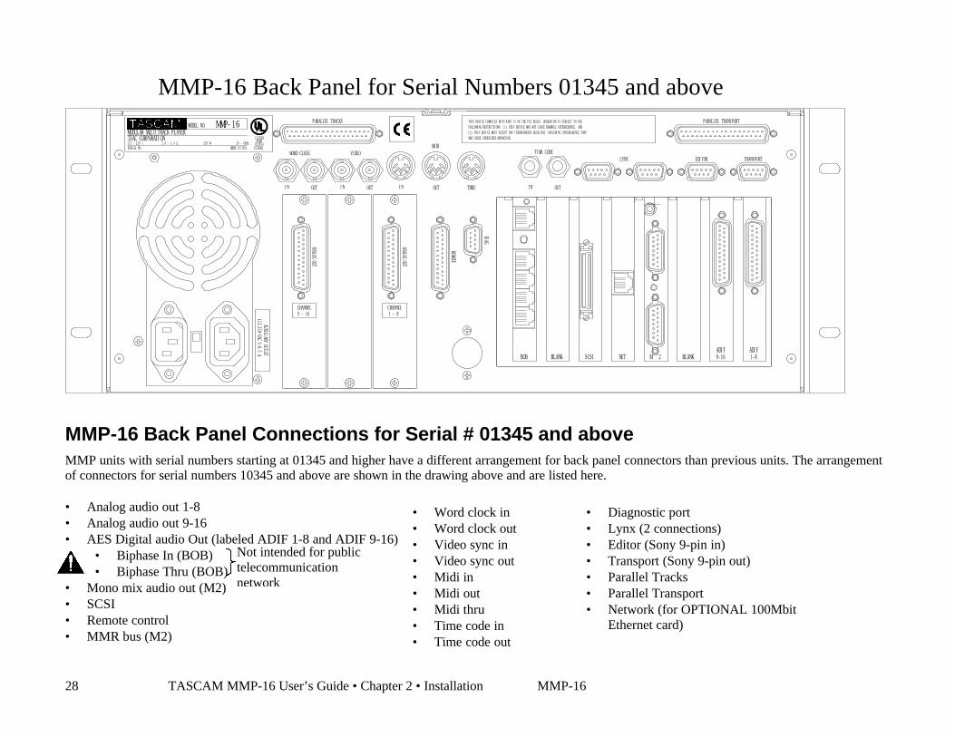
28 TASCAM MMP-16 User’s Guide • Chapter 2 • Installation MMP-16
PARALLEL TRACKS
115/230~VAC 1/0.5 AAUXILIARY OUTLET
9 - 16
MMP-16
2.0 / 1.0 A,TEAC CORPORATIONMODULAR MULTITRACK PLAYER
115 / 230 ~,SERIAL NO.
MODEL NO.
230 W
CHANNEL
ANALOG OUT
OUTIN
UL1950
LISTED
E1XXXXMADE IN USA50 - 60Hz XXDK
R
WORD CLOCK
BLANK
1 - 8
BOB NETSCSI M 2 BLANK 9-16ADIF ADIF
1-8
(2) THIS DEVICE MUST ACCEPT ANY INTERFERENCE RECEIVED, INCLUDING INTERFERENCE THATFOLLOWING RESTRICTIONS: (1) THIS DEVICE MAY NOT CAUSE HARMFUL INTERFERENCE, ANDTHIS DEVICE COMPLIES WITH PART 15 OF THE FCC RULES. OPERATION IS SUBJECT TO THE
REMOTE
CHANNEL
OUTIN
ANALOG OUT
IN OUT
VIDEOMIDI
DIAG
THRU IN OUT
MAY CAUSE UNDESIRED OPERATION.
TIME CODELYNX
PARALLEL TRANSPORT
EDITOR TRANSPORT
MMP-16 Back Panel Connections for Serial # 01345 and aboveMMP units with serial numbers starting at 01345 and higher have a different arrangement for back panel connectors than previous units. The arrangementof connectors for serial numbers 10345 and above are shown in the drawing above and are listed here.
• Analog audio out 1-8• Analog audio out 9-16• AES Digital audio Out (labeled ADIF 1-8 and ADIF 9-16)
• Biphase In (BOB)• Biphase Thru (BOB)
• Mono mix audio out (M2)• SCSI• Remote control• MMR bus (M2)
Not intended for publictelecommunicationnetwork
• Word clock in• Word clock out• Video sync in• Video sync out• Midi in• Midi out• Midi thru• Time code in• Time code out
• Diagnostic port• Lynx (2 connections)• Editor (Sony 9-pin in)• Transport (Sony 9-pin out)• Parallel Tracks• Parallel Transport• Network (for OPTIONAL 100Mbit
Ethernet card)
MMP-16 Back Panel for Serial Numbers 01345 and above
MMP-16 TASCAM MMP-16 Owner’s Manual • Chapter 2 • Installation 29
Audio Connections
All audio outputs (both analog and digital) of the MMP-16 use DB-25 connectors. The pin configurationused on the DB-25 analog audio connectors is identical to that used for TASCAM DTRS format digitaltape machines such as the DA-88. Two female DB-25 connectors are used for the analog connections, onefor channel 1-8 and the other for channels 9-16, as labeled on the MMP back panel. Each of the digitaloutputs uses a female DB-25 connector to carry eight channels of AES/EBU digital output signals (twosets of four stereo pairs). These are labeled as digital outputs 1-8 and 9-16.
Analog Output Connections
All analog outputs use balanced signals designed to mate with standard 600-ohm devices using +4 dBulevels. Analog audio processing is done on two separate 20-bit Digital to Analog converter cards mountedwithin the MMP-16. These converters are mounted in a special shielded cage within the MMP and areattached via ribbon cable to a card (labeled AO) plugged into one of the system ISA bus slots on the PCmotherboard. These D/A boards have their own power supply separate from the main PC power supply.Max load is 12.28 VRMS.
Digital Output Connections
Two female DB-25 connectors are used to provide four stereo digital outputs each, for a total of sixteenchannels of digital audio output. Two TASCAM DA-88 analog I/O cables should be used as digitaloutput cables. Even though the MMP-16 has no audio inputs, the digital input 1&2 pair on the first digitalinput cable is the default reference input for the AES/EBU clock reference. This can be changed to usedigital input 3, 5, or 7 from one of the other three digital input pairs using Setup Menu 600 (Dig In RefTrack).
NOTE: The digital clock signals coming from any external device connected to the AES/EBU inputs willforce the MMP-16’s internal clock to try to lock to it when digital input is selected (Setup Menu 500).This can cause playback problems if the clock source is not accurate. If this occurs set that track to use thesample rate converter in Setup Menu 500 (Input Source).
Monitoring Connections
For monitoring at the MMP-16 there is a mono headphone jack on the front panel (compatible with stereoheadphones of either low or high impedance). For studio Cue or remote monitoring there is a rear panelline level mono mini phone jack. It is an unbalanced output designed to be connected to externalamplification.
The front panel headphone monitor jack is controlled by the LEVEL control located next to the jack onthe front panel. Press the MON key and select the desired tracks using the Track Select keys to choosewhich of the MMP-16 tracks will be summed to appear at the headphone jack output. The rear panel jackis a pre-LEVEL control, so it is a fixed line level output (-10 dBu), and it always presents a summedoutput of the audio channels selected using the MON function on the front panel.
30 TASCAM MMP-16 User’s Guide • Chapter 2 • Installation MMP-16
Timecode and Video Reference Signals
To accurately synchronize the MMP-16 to film or video, or with other audio playback equipment, somemethod of providing a stable timing reference must be used. Because the MMP-16 is very flexible, thereare numerous methods one could use to connect film and video equipment. The best method dependsupon the chosen method of sync, the other equipment that is being controlled, and whether the MMP-16will be the master or a slave to the other equipment. This section covers the various reference signalsavailable on the MMP-16 system and their applications.
Video In/Out
Most video post houses have a common house sync signal to lock all the audio and video equipment inthe facility to a standard video reference signal. This insures that all devices receiving the house syncsignal will lock together to the edge of the video frame. The house sync signal can be black burst,composite sync, or color bars in NTSC or PAL format. The house sync video reference signal should beconnected to the VIDEO IN connector on the back of the MMP-16. To loop the connection through theMMP, connect the MMP VIDEO OUT to the next device that will use the house sync signal. If there isnot a loop through connection then the VIDEO OUT may need to be terminated, depending upon thefacility signal design. To set the MMP frame reference to use this video input, choose setup menu 001,Frame Reference, and set the value of this parameter to be Video Reference.
SMPTE/EBU Time Code In/Out
The MMP has two stereo phone jack connections using ¼” Tip/Ring/Sleeve connectors (with the tipbeing + and the ring being - on a balanced signal) for synchronizing the operation of the MMP to otherdevices using SMPTE/EBU Longitudinal Time Code (LTC). To synchronize the MMP to an externaldevice which outputs SMPTE/EBU LTC, connect the time code audio output of the master device to theMMP TIME CODE IN jack. The MMP-16 can also generate a stable SMPTE/EBU time code output(equivalent to a time code track signal) that can be used to synchronize external equipment or to stripetime code onto tape. The TIME CODE OUT jack will always output SMPTE/EBU LTC when the MMPis playing.
MMP-16 TASCAM MMP-16 Owner’s Manual • Chapter 2 • Installation 31
Biphase Connections
Biphase is a control signal typically generated by a film projector and is traditionally used to interlock theoperation of the film with sprocketed magnetic tape machines. The Biphase Operations Board (BOB) onthe back panel of the MMP has four biphase input connections and one biphase throughput connection forsynchronizing the operation of the MMP-16 to film transports. Use Setup Menu 100, Sync Group, toselect which of the four Biphase inputs (Sync Groups) will control the system. The biphase connectionsuse 6-pin modular RJ-12 connectors (like those used on commercial phone systems) and twisted multi-pair cabling (Category 5 Ethernet). Up to 100 feet of cable can be typically run from a biphase device tothe MMP-16 or vice versa. The pinout diagram for these connectors is given in Appendix D: CableInformation.
Unlike time code, Biphase gives only speed and direction and does not contain an absoluteaddress. To set the MMP to lock to biphase, use Setup Menu 000, Control Mode. The various
biphase parameters such as frame rate, pulse rate, acceleration, etc. are set in the 300 series Setup Menus.Not intended for public telecommunications network connection.
Digital Audio Sample Reference Connections
In combination with a frame reference for video and film, there may also be a sample reference for theaudio. The sample reference can be taken from the digital input 1&2 on the Digital output cable, theframe reference, the Word Clock input (if there is an active signal on that input), or the system’s internalclock source. These connections are described here in more detail.
Word Clock
Word Clock is a digital reference signal used by many digital editors and digital tape machines. Thispermits two digital audio devices to synchronize their sample clocks to facilitate digital audio transfersbetween machines, and to insure that they are running at precisely the same sample frequency. The signalis transmitted on an unbalanced coaxial cable that terminates into a BNC connector at the MMP-16 end.The MMP-16 has both a digital WORD CLOCK IN and a digital WORD CLOCK OUT connection usingBNC connectors.
When an external tape machine is to control the sample rate of the MMP-16, connect the Word Clockoutput from that machine to the WORD CLOCK IN on the MMP-16. When the MMP-16 is to control thesample rate of an external machine connect the WORD CLOCK OUT from the MMP-16 to the WordClock In on the controlled machine. The maximum practical cable distance is up to 100 feet. Use setupmenu 002 to select the sample reference for the MMP-16 system. Normally this is a 48 kHz TTL-compatible (5 volt) signal.
AES/EBU Sample Rate
To lock the digital sample clock to an AES digital audio source, the audio sample reference for the MMP-16 can be taken from the digital audio input 1&2 pair on the connector used for the AES digital output.Use setup menu 002 to select the sample reference for the MMP-16 system.

32 TASCAM MMP-16 User’s Guide • Chapter 2 • Installation MMP-16
MIDI Connections
The MMP-16 has MIDI (Music Instrument Digital Interface) In, Out, and Thru connectors. These areused for sending MIDI Time Code and for controlling the transport via MIDI Machine Control.
The MMP MIDI OUT connector carries a MTC signal generated by the MMP-16 whenever the unit is inPlay. To slave MIDI devices that can follow MTC (MIDI Time Code) to the MMP-16, connect the MMPMIDI OUT connector to MIDI In port of the external device. The MIDI out signal (and the MIDIThrough signal, if it is set as a second MIDI output) will contain any MMP-16 responses to the MMCinput commands in addition to MTC generated by the MMP-16 from the time code reference source.
The MIDI IN port on the MMP can receive MIDI Machine Control messages for operating the MMP’sbasic transport control functions. The MIDI THRU jack on the MMP will pass through any MIDI signalsappearing at the MMP MIDI IN port.
External Controllers & Bus Connections
In most installations the MMP-16 will be rack mounted in a machine room and thus will either be remotecontrolled through slaving to another time code-based machine (typically a VTR) or to a biphase machine(typically a film transport). Any controller that has a Lynx port can also directly control, or be controlledby, the MMP-16 (the TimeLine Lynx Keyboard Control Unit and the TimeLine Lynx-2 module are twoexamples). There is also a fully featured remote, the TASCAM MM-RC, which is specifically designed tocontrol multiple MMR and MMP units.
Lynx Bus / KCU Connection
The TimeLine Lynx Keyboard Control Unit (KCU) can be used with the MMP-16. Multiple units may bedaisy-chained using either of the two LYNX connectors as input. The other LYNX connector could betied to another MMP-16, or to a Lynx module for controlling other tape machine transports. The LynxKCU can control a total of up to six machines.
MMR Sync Bus Connections
The real power of the MMR-8/MMP-16 system comes into play when multiple MMP-16s are tiedtogether using the MMR Bus to create larger “virtual” audio playback machines. The MMR bus supportsup to 100 MMP-16s, all tied together to create up to an 800-track playback system that could becontrolled by a single MMP-16, MM-RC Remote, Lynx KCU, or other machine remote controller.
The MMR Bus connects each MMP-16 using a 15-pin connector located on the SYNC card connector onthe MMP back panel. Two DB-15 connectors are provided on the back of each MMP-16 so that multiplemachines can be daisy-chained together. The system is auto terminating. To add MMP-16 units to thesystem, connect a cable from the last unit in the chain to the new unit.
The MMP Bus is made active on each machine by choosing the MMP Master or Slave setting in SetupMenu 110, MMP Bus Request. All of the MMP-16s that are tied together can then be software divided(Setup Menu 100) into four Sync Groups, each featuring fully independent control within their group. Allof the MMR/MMP machines that are connected, Online, and set to the same sync group can then becontrolled together. The MMR Bus thus turns three MMP-16s into a single 48-track playback machine,six MMP-16s into a 96-track machine, and so on up to 100 MMP-16s functioning as a single 1600-trackplayback machine. Any MMP-16 tied onto the MMR bus can also be individually taken off-line andcontrolled locally at any time. MMR and MMP Units can be added or dropped from Sync Groups usingthe Online key on the front panel.
MMP-16 TASCAM MMP-16 Owner’s Manual • Chapter 2 • Installation 33
Serial Transport Connection
The TRANSPORT connection uses the industry-standard RS-422 Sony 9-pin P2 protocol (Ampex VPR-3is also supported) for controlling external serial transports such as audio or videotape machines. It isintended for transport control of a single external device. This port will send out the appropriate transportcommands when the transport functions of the MMP are engaged through the front panel or via the MM-RC Remote controller. Use Setup Menu 000 (Control Mode) to set the MMP to control external devicesvia the Serial Transport connection. A video reference source is recommended for this type of operation.
Serial Editor Connection
The EDITOR connection uses the industry-standard RS-422 Sony 9-pin P2 protocol. The Editorconnection allows for controlling the MMP-16’s transport functions from a standard Video editorcontroller or other external device. Use Setup Menu 000 (Control Mode) to set the MMP for control viathe Editor connection. A video reference source is required for this type of operation.
Parallel Transport
The PARALLEL TRANSPORT connector allows use of remote control devices that operate by sendingmessages via parallel signals for the motion control keys. There are +12 volts available to drive switchlamps in conjunction with the tally outputs that are available for each key. The pinout diagram for theParallel transport connector is given in Appendix D: Cable Information.
Parallel Tracks
Since there are no audio inputs on the MMP-16, the PARALLEL TRACKS connector has no function inthe current software release. The Parallel tracks connector may be used in future releases of the MMP-16.

34 TASCAM MMP-16 User’s Guide • Chapter 2 • Installation MMP-16
Connecting External SCSI MediaThe MMP-16 SCSI interface card is pre-set to SCSI ID 7. The internal Kingston drive receiver in theMMP-16 is set to SCSI ID 0. Each device added in the SCSI chain must have a unique SCSI ID numberor else the MMP-16 will not boot properly.
External SCSI connections should be made using the shortest possible length of double-shielded SCSI-2cables with 110 ohms impedance. Only the last drive in the chain is terminated. All other drives musthave their terminating resistors removed or have termination jumpers set to off (including those drivesplaced in the MMP-16 internal drive slot). SCSI cables are readily available from most computer stores.For the most reliable operation, the total length of all SCSI cabling must not exceed 15 to 20 feet.
All drives must be pre-formatted using a single partition. Drives with capacities of up to 9 GB have beentested and found suitable for use with the MMP-16. The MMP-16 system plays all audio from separateuncompressed 16-bit or 24-bit linear files. Approximately 5 MB (Megabytes) of disk space is required foreach minute of audio recorded per track. Thus a 4 GB drive can hold about 12 track hours of 16-bit audio,while a 2 GB drive will hold about 6 track hours.
SCSI CablesThere is a considerable difference in quality and performance of cables used to connect SCSI devices. It isimperative that users pay close attention to this issue.
Cable QualityHigh quality SCSI cables are essential for proper MMR/MMP system performance. Low quality cables,which are often thin, may cause data transmission errors, file corruption, and system malfunctions. This isoften due to improper and insufficient grounding, incorrect pin wiring, and unwired pins. The followingSCSI cable manufacturers are highly recommended as a source for MMR/MMP SCSI cables:
Cable Length and Device SupportThe MMR/MMP SCSI host card supports from one to eight SCSI devices. However when one to fourSCSI devices are connected, total cable length should not exceed three meters. When five to eight SCSIdevices are connected, total cable length should not exceed 1.5 meters. Note that total cable lengthincludes the internal cabling in carriers or drive bays. Thus if a 4-bay drive enclosure contains ribboncable internally that measures one meter in length, the external cable must not exceed 2 meters. Impropercable length often causes an MMR system to freeze while mounting volumes. (Note: Paralan can providecustom-length SCSI cables).
Black Box Corporation -www.blackbox.com1000 Park Drive Lawrence, PA 15055-1018Tel: 724-746-5500 || Fax: 724-746-0746email [email protected]
Paralan Corporation -www.paralan.com4655 Ruffner St., San Diego, CA 92111Tel. (619) 560-7266 || Fax 619-560-8929email: [email protected]

MMP-16 TASCAM MMP-16 Owner’s Manual • Chapter 2 • Installation 35
Cabling Wide and Narrow Devices in a SystemNARROW SCSI uses 8-bit data transfers. It generally uses a 50-pin connector.
WIDE SCSI uses 16-bit data transfers. It generally uses a 68-pin connector. Wide SCSI may also refer to32-bit SCSI data transfers but 32-bit wide SCSI is not as common.
Narrow drives should always be placed at the end of a SCSI chain. This is due to the fact that when aWide to Narrow connection is made, 8 bits are not passed through, so the Wide drive (and all subsequentSCSI devices in the chain) receives only 8 bits of data instead of 16. If a Narrow drive is connected after aWide drive, the Wide drive still receives all 16 bits of data.
SCSI TerminationA terminator provides electrical circuitry at the end of a SCSI chain to prevent the reflection of electricalsignals when they reach the end of the chain. The SCSI bus requires termination only at the ends of theSCSI chain, not in the middle. There are several types of SCSI Termination: Passive, Active, ActiveNegation, Force Perfect Termination, and Low Voltage Differential.
The MMR/MMP should only use Active terminators. This is because active terminators involve avoltage regulator to reduce fluctuation effects in termination power to insignificance. This results in morestable SCSI signals, less signal reflection and fewer data errors. Active negation terminators are mostoptimized for Fast- and Ultra-SCSI speeds. Active negation termination is currently not under testing andthus is not supported by TASCAM.
Kingston Frame ConfigurationWhen configuring a Kingston receiving frame the settings in Figure 1 must be used.Note: All but one setting are factory defaults. Jumpers should be installed on W3, W1 and pins 1&2 of J6(Figure 1). Jumper W2 determines termination. In the “A” position (default) termination resistors aredisabled (This is the recommended configuration for most external applications). In certain conditions itmay be desirable to terminate at the frame, for example, if an internal bay is being installed in theMMR/MMP. If this is the case jumper W2 should be set in the “B” position

36 TASCAM MMP-16 User’s Guide • Chapter 2 • Installation MMP-16
Figure 1
Wide SCSI Cards and Kingston FramesThe MMR/MMP are normally shipped with a narrow Symbios SCSI card. The MMR/MMP unitsalso support the Symbios SYM8751SP Wide SCSI card. To install a wide SCSI card, use agrounding strap and follow the installation instructions below:
Removing the Narrow Host Adapter (Symbios SYM 8600SP)1) Disconnect the 26-pin ribbon cable from J2 on the MMR Biphase Operations Board, and fold out
of the way.2) Disconnect the 50-pin ribbon cable from J2 on the Symbios SYM8600SP SCSI host adapter.3) Remove the Phillips head screw that secures the host adapter to the chassis.4) Carefully remove the host adapter.
Installing the Wide Host Adapter (Symbios SYM8751SP)1) Prior to inserting the wide host adapter into the PCI slot, connect the 50-pin ribbon cable to J4 on
the SYM8751SP. This connector is located on the side of the card, which makes it very difficultto install if the card is already in the PCI slot.
2) Insert the wide host adapter into the same PCI slot that previously contained the narrow adapter.3) Secure the wide host adapter to the chassis with the Phillips head screw.4) Reconnect the 26-pin ribbon cable to J2 on the MMR Biphase Operations Board.

MMP-16 TASCAM MMP-16 Owner’s Manual • Chapter 2 • Installation 37
Wide Kingston Drive FramesThe Kingston SCSI drive frame in the MMR is normally configured for narrow SCSI. TASCAM can alsoprovide MMR/MMP units configured with wide Kingston frames and carriers, and can perform a serviceupgrade to remove the existing narrow Kinston frame and carrier and replace it with a wide Kingstonframe and carrier. Contact your TASCAM representative for pricing and availability on these wide units.Note that a narrow drive carrier will not fit into a wide frame, and vice versa.
It is possible to mount a narrow SCSI drive in a wide Kingston carrier (or vice versa) by means of anadapter inside the carrier. One source for these adapters and other SCSI cable peripherals can be found at:
CS Electronics17500 Gillette Ave.Irvine, California 92614Tel (949) 475-9100 Fax (949) 475-9119http://www.scsi-cables.com/Index.htm
CS Model # ADP-9051 is for HD68-pin male to 50-pin male (mounts a wide drive in a narrow carrier)
CS Model # ADP-9056 is for HD68-pin female to 50-pin female (mounts a narrow drive in a widecarrier).
Approved SCSI DrivesThe following disk drives have been approved for use with the MMR-8 as of July 19, 1999:
DriveManufacturer
DriveModel
FirmwareVersion
Seagate ST118273LW 6246Seagate ST19101W 0014Seagate ST318203LW 0001Seagate ST318275LW 0001Seagate ST32272N 0876Seagate ST34371N 0484Seagate ST34573N 5958Seagate ST34573W 5764Seagate ST39102LW 0005Seagate ST39173N 5764Seagate ST39173W 5764Seagate ST39173LW 6264Nikon* DD53-SIP Beluga AV UnknownIBM DCHS09F 2222
Manufacturers frequently release new drive models and obsolete other drive models. The most current listof approved drives can be found on the TASCAM web site at http://www.tascam.com .
* Users should be aware these drives do not perform as well as hard drives. Test results with the NIKONBeluga drive with 1K/sector media show 8 tracks of record and playback in 16- or 24-bit TapeMode isgenerally reliable. Non-destructive mode performance is less reliable, especially with heavy edit density.
38 TASCAM MMP-16 User’s Guide • Chapter 2 • Installation MMP-16
DVD RAM SupportThe MMR/MMP will support SCSI backup and export to DVD RAM disks as of software version 3.1.Testing so far indicates that these drives are several times slower than Magneto-Optical disks forrecording and transfers. Playback of a limited number of tracks is possible from a DVD RAM disk, butmaximum performance seen to date is 6 channels of 16-bit material in TapeMode.
LIMDOW Optical DrivesFor backing up files, and for ease of moving smaller projects around, we recommend using a“LIM/DOW” (Light Intensity Modulation / Direct Over Write) type optical disk. The LIM/DOWtechnology achieves better performance than is available on older types of Magneto-Optical media, whichmust execute an erase pass before they can write new data to the disk. The Nikon Beluga AV MO(Magneto-Optical) disk drive has been tested and rated to perform well when used with the MMP-16. Achart of currently tested and certified disk drive media is given in Appendix B, MMR Approved DrivesList. The results from performance tests of the NIKON Beluga AV MO drive with 1K per sector mediaare also given there. It is possible to use other removable media such as the IOMEGA Jaz drive and theSyQuest Syjet, but these do not provide the same level of performance for recording as a hard drive andthey are more fragile than optical drive media. Use these devices at your own risk, as they are notsupported as primary record or playback devices DAT, Exabyte and other streaming tape device cannotcurrently be used with the MMP-16 system.
MMP-16 TASCAM MMP-16 Owner’s Manual • Chapter 2 • Installation 39
Remote Controllers for the TASCAM MMP-16
TASCAM MM-RC The TASCAM MM-RC is a dedicated remote control unit designed specially foruse with the MMP-16 and the MMP-16 sixteen channel player unit. It connects to aspecial remote connector on the UI/B card on the back of the MMR and MMPunits. This remote allows complete control of all attached functions of the MMRand MMP units, including all setup menus. It also allows for machine grouping aswell as system wide control of all attached units. A total of up to 100 units (anycombination of MMR and MMP) can be controlled from the MM-RC.
Lynx KCU The TimeLine Lynx Keyboard Control Unit (KCU) is a tabletop controller which istypically used in conjunction with Lynx 2 synchronizer modules. It provides a timecode display, motion control functions (including a jog/shuttle Wheel), trackselections, and audio editing functions for most professional video and audiotransports. The KCU can remotely control the operation of a total of up to sixtransports including MMP-16s. When used with the KCU 900 software, the LynxKCU unit allows control of the following MMP-16/MMR-8 functions:
• Transport Control• Track Record Arm/Select (Record arm only for MMR-8)• Slip Track/Region• Undo/Redo• Goto Prev/Next Edit• Goto Head/Tail• Clear/Paste
The Lynx KCU may be directly connected to either of the two integrated Lynxports on the MMP back panel. The second Lynx connector provides a loop thruconnection to an external Lynx module for control of other devices from the KCU.
The TimeLine Lynx KCU is available from:
TimeLine Vista, Inc.1755 La Costa Meadows Drive, Suite BSan Marcos, CA 92069Tel: (760) 761-4440 Fax: (760) 761-4449
Keyboard Operation (with MM-RC option)The optional MM-RC (Remote Control unit) has a keyboard connector located on the rear panel whichaccepts a standard PC-AT style keyboard. The purpose of the keyboard is to facilitate selecting menuitems while in the Setup Mode and to make it easier to name Projects and Tracks. There is no way toconnect a keyboard directly to the MMR or MMP – this must be done using the MM-RC.
Note: The internal software of the MM-RC will be automatically updated when an MMR-8 or MMP-16 isbooted while attached to the MM-RC. Be sure the power switch of the MM-RC is on while theMMR/MMP unit is started so the unit can sense the presence of the MM-RC remote.
40 TASCAM MMP-16 User’s Guide • Chapter 2 • Installation MMP-16
Using the PC KeyboardUse the keyboard to perform the following data entry tasks on the MMR or MMP:
• Enter Project and Track names directly by using the standard alphanumeric keys.• Enter Tape Mode Start time, Pre-Roll and Post-Roll directly using the number keys.• Access Menu Banks directly by using the Number keys.• Use the Up and Down arrow keys on the keyboard to scroll through the Setup Menus.• Use the Up and Down arrow keys to scroll through menu parameters. Once the desired menu is
reached, press F1 to toggle the Trim key function.• Pressing Enter on the keyboard has the same effect as pressing STO on the MMR or MMP front panel
and will store the parameter selection displayed in the LCD.
Not all keys on the PC keyboard are active. Use the following keys:
F1 – Press F1 to enter Setup. Once Setup Mode has been entered, F1 will toggle the TRIM key on theMMP front panel.
Escape (Cancel) key – This key is equivalent to the Cancel (CLR) key on the MMP front panel. PressEsc to leave the Setup Mode and return to the Normal Display State.
Arrow keys - These serve the same function as the Arrow keys on the MMP front panel.
Enter key - Equivalent to STO on the MMP front panel. When a menu or parameter setting has beenchanged pressing Enter stores the new parameter.
Shift key - Acts like a standard keyboard Shift key, but will only work in conjunction with Letter keysand the Minus key.
Letter keys – May be used shifted or unshifted. Note that most punctuation keys are not supported.
Minus key - Shifted for Underscore, or unshifted for Minus/Hyphen.
Caps Lock - Works like a standard keyboard Caps Lock key.
Num Lock - When Num Lock is active (Num Lock is lit on the keyboard) use of the numeric Keypad isenabled. The Number keys and the Enter key are active in this mode, and they function exactly like theydo on the keyboard. When Num Lock is not active (the Num Lock light is not lit), the numeric keypadserves only as up (8), down (2), left (4), and right (6) arrows.
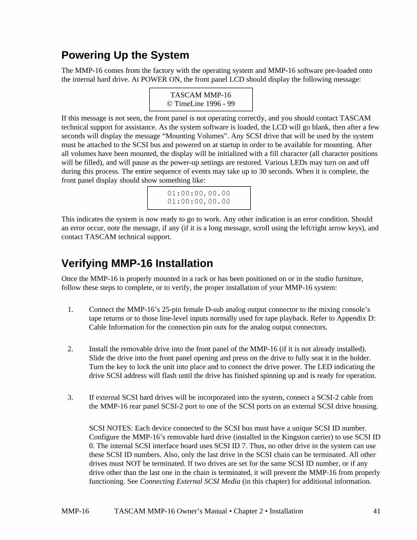
MMP-16 TASCAM MMP-16 Owner’s Manual • Chapter 2 • Installation 41
Powering Up the SystemThe MMP-16 comes from the factory with the operating system and MMP-16 software pre-loaded ontothe internal hard drive. At POWER ON, the front panel LCD should display the following message:
If this message is not seen, the front panel is not operating correctly, and you should contact TASCAMtechnical support for assistance. As the system software is loaded, the LCD will go blank, then after a fewseconds will display the message “Mounting Volumes”. Any SCSI drive that will be used by the systemmust be attached to the SCSI bus and powered on at startup in order to be available for mounting. Afterall volumes have been mounted, the display will be initialized with a fill character (all character positionswill be filled), and will pause as the power-up settings are restored. Various LEDs may turn on and offduring this process. The entire sequence of events may take up to 30 seconds. When it is complete, thefront panel display should show something like:
This indicates the system is now ready to go to work. Any other indication is an error condition. Shouldan error occur, note the message, if any (if it is a long message, scroll using the left/right arrow keys), andcontact TASCAM technical support.
Verifying MMP-16 InstallationOnce the MMP-16 is properly mounted in a rack or has been positioned on or in the studio furniture,follow these steps to complete, or to verify, the proper installation of your MMP-16 system:
1. Connect the MMP-16’s 25-pin female D-sub analog output connector to the mixing console’stape returns or to those line-level inputs normally used for tape playback. Refer to Appendix D:Cable Information for the connection pin outs for the analog output connectors.
2. Install the removable drive into the front panel of the MMP-16 (if it is not already installed).Slide the drive into the front panel opening and press on the drive to fully seat it in the holder.Turn the key to lock the unit into place and to connect the drive power. The LED indicating thedrive SCSI address will flash until the drive has finished spinning up and is ready for operation.
3. If external SCSI hard drives will be incorporated into the system, connect a SCSI-2 cable fromthe MMP-16 rear panel SCSI-2 port to one of the SCSI ports on an external SCSI drive housing.
SCSI NOTES: Each device connected to the SCSI bus must have a unique SCSI ID number.Configure the MMP-16’s removable hard drive (installed in the Kingston carrier) to use SCSI ID0. The internal SCSI interface board uses SCSI ID 7. Thus, no other drive in the system can usethese SCSI ID numbers. Also, only the last drive in the SCSI chain can be terminated. All otherdrives must NOT be terminated. If two drives are set for the same SCSI ID number, or if anydrive other than the last one in the chain is terminated, it will prevent the MMP-16 from properlyfunctioning. See Connecting External SCSI Media (in this chapter) for additional information.
01:00:00,00.0001:00:00,00.00
TASCAM MMP-16© TimeLine 1996 - 99
42 TASCAM MMP-16 User’s Guide • Chapter 2 • Installation MMP-16
4. Connect the MMP-16 to the applicable timing reference source and to the appropriate remotecontrol interface
a. To connect the MMP-16 to a film transport, connect the biphase sync output from theprojector to one of the four biphase inputs. The four biphase inputs are numbered 1 - 4 from topto bottom. Any, or all, of the inputs can be connected. Use Setup Menu 100, Sync Group, toselect which of the four Biphase inputs (Sync Groups) will control the system.
b. To connect the MMP-16 as a slave to a video machine, first connect a source of Video Framesynchronization to the MMP-16’s VIDEO IN (either the Video Reference out from a video deck,or a Video black burst signal). This is normally a loop-through connection so the MMP-16’sVIDEO OUT jack should be terminated if it is not connected to another machine. Nextconnect the Time Code signal from the video to the MMP-16, using the SMPTE/EBU TIMECODE IN (LTC) connector. Use the RS422 Sony 9-Pin Editor port to control the MMP-16 viaSony protocol. To connect the MMP-16 as a master for a video deck, connect the TRANSPORTconnector to the video deck’s Sony P2 protocol-compatible remote control connector.
c. To connect the MMP-16 to other audio devices, connect the TIME CODE IN/OUTconnectors. If the other devices do not read or transmit SMPTE/EBU time code, but they do readMTC (MIDI time code), then connect the MIDI IN/OUT/THRU as required.
To connect multiple MMP-16 Players together, daisy chain them using the MMR Bus (the15-pin SYNC connectors). A 3-foot MMR bus cable is provided with each MMP-16 for thisapplication. Since each connector parallels the other, connection order is not critical. The MMRBus is self-terminating.
e. If remote control capabilities are desired, then connect a TASCAM MM-RC remote controlunit to the 25 pin D-sub connector on the UI/B board on the back panel of the MMP-16. Somefunctions of the MMP-16 can also be controlled via the TimeLine Lynx Keyboard Control Unit(KCU) by connecting the KCU to either LYNX connection (they operate in parallel, so eitherone may be used) on the MMP-16 back panel. If necessary the other LYNX connection can bedaisy-chained to other equipment (MMP-16, a Lynx-2 controller, etc.).
Software Updates
Software updates are available on the TASCAM Web site at http://www.tascam.com, and may bedownloaded onto one or more floppy disks. To install the software update, insert the floppy disk (or Disk1, if multiple disks are received) into the front panel floppy drive while the unit is operating normally.Access Menu 995 (Load Software) and press STO. The system will ask “Are you sure?” Confirm thefloppy is properly inserted and press STO again to confirm. If multiple disks are supplied, the operatorwill be prompted via the display to remove Disk 1 and place Disk 2 into the drive. After the softwareupdate is installed, the system will display a message that the update is complete, and will display achecksum number (written on the floppy update disk for reference) to verify that the installation has beensuccessful. Remove the floppy disk and recycle the power to operate the unit with the new softwareinstalled. All system floppy disks should be kept in a secure location in case they are needed in the future.
MMP-16 TASCAM MMP-16 Owner’s Manual • Chapter 2 • Installation 43
Factory Default SettingsThe MMP-16 is shipped from the factory using a pre-defined set of operating parameters. The factorydefault settings can be changed in the field at any time through a system of Setup menus that control theMMP-16 operating parameters. The new value settings will be automatically saved and used at systemstart-up as the normal operating parameters of the MMP-16. The system can be reset to use the factorydefaults at any time by accessing menu 901 (“Recall Settings”), and selecting the “Default” value. Thesystem will then be returned to the factory default settings and is ready to use.
44 TASCAM MMP-16 User’s Guide • Chapter 3 • Keys and Status Displays MMP-16
Chapter 3 MMP-16 Keys and Status Displays
MMP-16 Keys & DefinitionsThroughout this manual several abbreviations and written shortcuts are used to define user operations andmachine functions. The following summarizes how these abbreviations and text shortcuts relate to theoperational description:
Keys Refers to the colored front panel keys on the MMP-16. The gray keys are used toenter time code numbers (on the numeric keys) and to perform various othercommon functions. The shift key is the only yellow key. Key use in the text isindicated through capitalizing the key legends (e.g., LOAD TRACK indicates theLoad Track key is to be pressed).
Shift Key This key, the only yellow key on the front panel, functions like the shift key on acomputer keyboard. Located at the top-right corner of the numeric keypad area,shift works in combination with selected gray keys, enabling their shiftedfunctions. The shifted function for each applicable gray key is written above thekey on the front panel metal. Press and release the shift key before pressing anyother key, to “latch” the shift key until the desired key is pressed. This will light theshift LED above the SHIFT key. Pressing another key while the shift LED is onwill cause that key to execute its shifted function. Once the shifted function hasbeen activated, the shift LED will go off and the system will return to the normalnon-shifted state. If multiple shifted keystrokes are required, you may also pressand hold SHIFT (the shift LED above the key will stay on) while pressing one ormore gray keys in succession.
In the text “SHIFT+X” indicates the Shift key is used in combination with one ofthe gray keys (X) that has a shifted function. Thus, SHIFT+TRIM means “pressand release (or press and hold) the SHIFT key and then press the TRIM key.” Inthis case, the MMP-16 will enter Dynamic Trim mode since the shifted function forthe TRIM key is “Dynamic Trim” (which is indicated above the key). To cancelshift, when the shift LED indicator is on, press SHIFT again, or press CLR.
Text Above Keys Indicates the “shifted function” for that key. Pressing SHIFT+ key, as detailedabove, accesses the shifted function.
Reversed TextAbove Keys Indicates the “alternate” function for the JOG and SHTL keys, and for the STO,
RCL and CLR keys. The alternate functions are used in Setup, Track, Verify, andError modes, and while trimming values. In Normal mode, the key functions arenormal (i.e., pressing JOG turns the Wheel into a Jog Wheel). In Setup or Trackmodes, pressing JOG indicates a left-arrow function as a cursor or windowmovement tool.
MMP-16 TASCAM MMP-16 Owner’s Manual • Chapter 3 • Keys and Status Displays 45
Mode This term is used to refer to the active Control mode selected by Setup menu 000and to refer to the Track Select Mode which governs the behavior of the SEL keys.It may also be used to refer to various operational modes such as Loop, Trim, orShift which change the meaning of other keys or controls as long as the mode isactive.
LCD Text To indicate the front panel LCD text, curly brackets are used to enclose the text.(e.g., {X. 01:00:00,00}) A mono-spaced Courier font duplicates thespacing and alphanumeric characters shown in the LCD. In the Normal state, thetop line of the LCD typically shows the current “play head” time code, while thebottom line shows the entry (or other active) register time code. In Setup, Track,Verify, or Error states, the two LCD lines will change to show various textmessages as indicated in the Functional Overview section of Chapter 2.
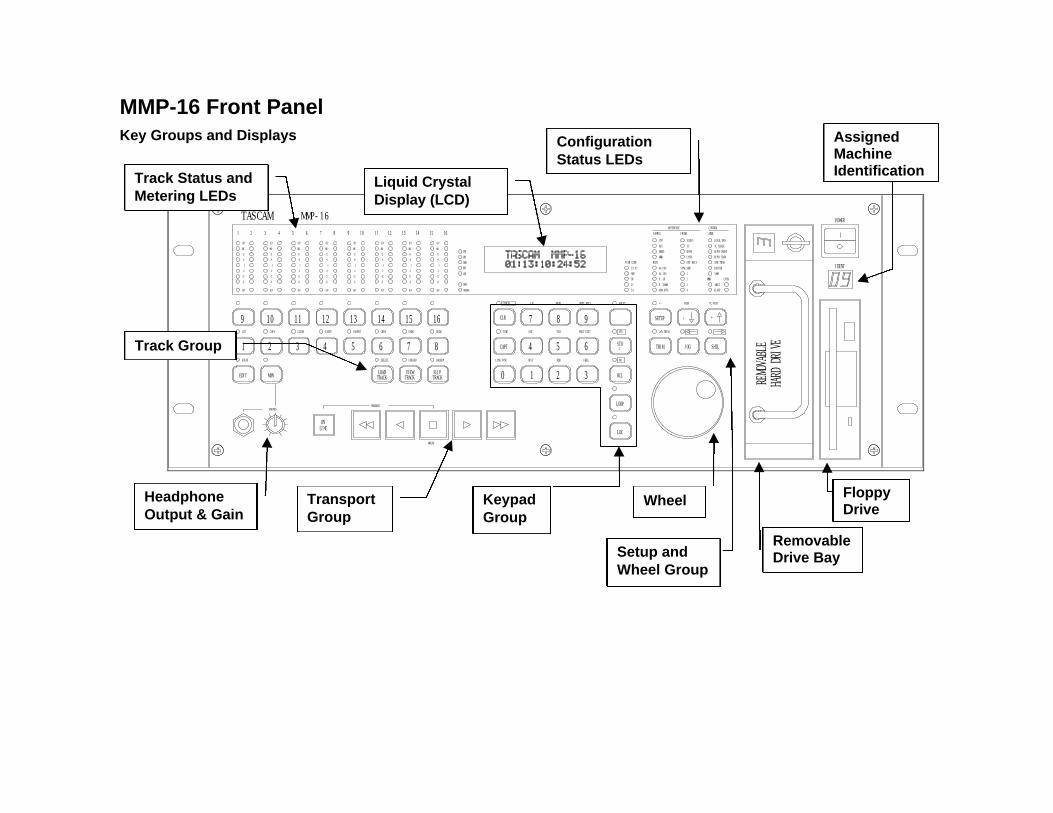
MMP-16 Front PanelKey Groups and Displays
-12
-25
SLIP
12
LINEON
PASTE
4
EDIT MON
1EVENT
2 3
COPY
9CUT
10
-6
SLIP
-25
-12
0 0
-12
-6
-25
SLIP
11CLEAR
-12
-6
-25
SLIP
0
TRACK
5
VIEWLOADTRACK
6DELETE
7UNLOAD
13INSERT
0
-6
0
-12
-6
-25
SLIP
14OPEN
15UNDO
0
-12
-6
-25
SLIP
0
-12
-6
-25
SLIP
SLIPTRACK
8BACKUP
0
LYNX SYNC
CAPT
INTERLOCK
16REDO
-25
-12
-6
0
SLIP
ERROR
LOCK
BUSY
OFFSET
TIME
CLR
CANCEL
MMP-16
+12
MAX
CLIP
TASCAM
2
MAX
+12
+6
CLIP
1
+6
+12
MAX
CLIP
3
+6
+12
MAX
CLIP
54 6 7 11
+6
8 9
+6
+12
MAX
CLIP
10
+6
+12
MAX
CLIP
12
+6
+12
MAX
CLIP
13 14 16
+6
CLIP
15
+12
MAXTONE
MIDI
SER TRAN
EDITOR
MAST
VARI
SLAVE
TC/FEET
SHTL
LOC
STO=
SHIFT
YES
RCL
NO
LOOP
1 2
OFST
4RDR
5
3
FREE
6
OUT
IN
7TAIL
HEAD
8 9PREV EDIT
NEXT EDIT
TRIM JOG
P. DOWN
NON STD.
TRIM
SETUP
+/-
TIME CODE
NDF
29.97
25
24
DF
RATE
44.100
48.000
P. UP
-
SUBF
+
EXT RSLV
SYNC GRP
1
3
4
2 MMR
REMO
VABL
EHA
RD D
RIVE
LYNX
IDENT
LOCAL/BUS
BIPH TRAN
BIPH CHASE
TC CHASE
CONTROLREFERENCE
WORD
SAMPLE
MMR
AES
INT
FRAME
BIPH
LYNX
VIDEO
TC
MODE
POWER
PHONES
MOUNT
UNMOUNT
Track Group
Track Status andMetering LEDs
KeypadGroup
Setup andWheel Group
RemovableDrive Bay
AssignedMachineIdentification
FloppyDrive
HeadphoneOutput & Gain
WheelTransportGroup
Liquid CrystalDisplay (LCD)
ConfigurationStatus LEDs

47
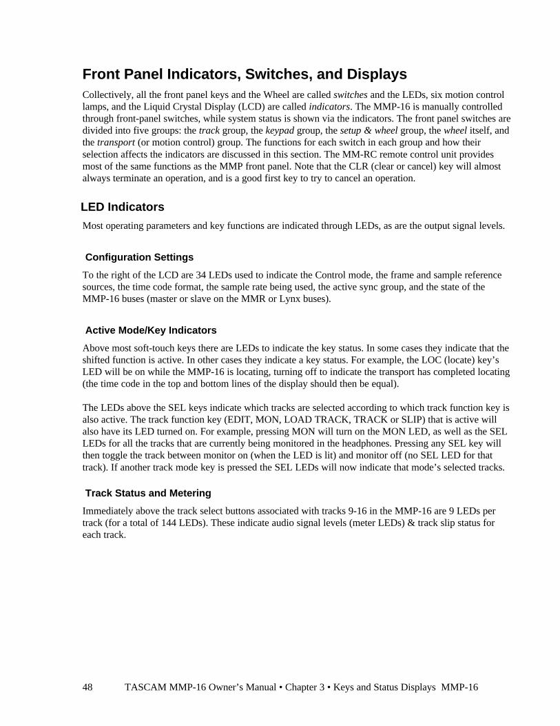
TASCAM MMP-16 Owner’s Manual • Chapter 3 • Keys and Status Displays MMP-1648
Front Panel Indicators, Switches, and DisplaysCollectively, all the front panel keys and the Wheel are called switches and the LEDs, six motion controllamps, and the Liquid Crystal Display (LCD) are called indicators. The MMP-16 is manually controlledthrough front-panel switches, while system status is shown via the indicators. The front panel switches aredivided into five groups: the track group, the keypad group, the setup & wheel group, the wheel itself, andthe transport (or motion control) group. The functions for each switch in each group and how theirselection affects the indicators are discussed in this section. The MM-RC remote control unit providesmost of the same functions as the MMP front panel. Note that the CLR (clear or cancel) key will almostalways terminate an operation, and is a good first key to try to cancel an operation.
LED Indicators
Most operating parameters and key functions are indicated through LEDs, as are the output signal levels.
Configuration Settings
To the right of the LCD are 34 LEDs used to indicate the Control mode, the frame and sample referencesources, the time code format, the sample rate being used, the active sync group, and the state of theMMP-16 buses (master or slave on the MMR or Lynx buses).
Active Mode/Key Indicators
Above most soft-touch keys there are LEDs to indicate the key status. In some cases they indicate that theshifted function is active. In other cases they indicate a key status. For example, the LOC (locate) key’sLED will be on while the MMP-16 is locating, turning off to indicate the transport has completed locating(the time code in the top and bottom lines of the display should then be equal).
The LEDs above the SEL keys indicate which tracks are selected according to which track function key isalso active. The track function key (EDIT, MON, LOAD TRACK, TRACK or SLIP) that is active willalso have its LED turned on. For example, pressing MON will turn on the MON LED, as well as the SELLEDs for all the tracks that are currently being monitored in the headphones. Pressing any SEL key willthen toggle the track between monitor on (when the LED is lit) and monitor off (no SEL LED for thattrack). If another track mode key is pressed the SEL LEDs will now indicate that mode’s selected tracks.
Track Status and Metering
Immediately above the track select buttons associated with tracks 9-16 in the MMP-16 are 9 LEDs pertrack (for a total of 144 LEDs). These indicate audio signal levels (meter LEDs) & track slip status foreach track.

MMP-16 TASCAM MMP-16 Owner’s Manual • Chapter 3 • Keys and Status Displays 49
Meter LEDs
Each track has its own column of signal level LEDs that read the MMP-16 analog output signal off disk.Each meter column contains eight LEDs. Functioning much like a tape machine’s peak meters, theirmeters have a fixed rise time of <30 ms and a default decay time of <0.5 seconds.
The bottom level LED (-25) is a green presence indicator. Any time there is signal on the track there willbe an indication. The next three LEDs indicate signal levels of -12, -6 and 0 VU. The next two LEDs areyellow and indicate +6 and +12 VU. The final two LEDs are red to indicate the audio peaks are at MAX(3 dB below clipping) and CLIP, which means the signal has most likely exceeded the input capability ofthe digital converter and may be distorted. The CLIP indicator acts as a peak-hold indicator duringplayback. It is only reset when the MMP-16 is stopped and put into PLAY again.
A de-facto film/video industry standard for digital device monitoring is that 0 VU should be set toindicate a signal level of -20 dBFS (decibels below full scale, i.e. 20 dB below the digital clipping level).The MMP-16 default setup follows this recommendation with the MAX LED indicator set to turn on witha signal 17 dB above the nominal 0 VU indication (just before all bits would be set true in the ADC). TheCLIP indication is typically adjusted for a 3 dB hotter signal (20 dB above 0 VU). These settings can beadjusted in 1dB increments using Setup mode menu 520 (Meter Reference Level) for any dB referencelevel from -15 dBFS to -24 dBFS.
See Chapter 8, Maintenance and Service for instructions on calibrating the outputs using the meters.
Machine Status LEDs
To the left of the LCD are 7 LEDs used to indicate the status of various MMP machine states (interlock,busy, lock, etc.). These are described here:
• The TONE LED is lit when menu 530 (Reference Tone) is set to On. Pressing play when this LED islit will cause all channels to output a 1kHz reference tone at 0 VU.
• The MIDI LED is used to indicate a valid MIDI input signal (MMC) is being received.
• The ERROR LED indicates an error state has occurred and must be cleared before normal operationcan resume.
• The BUSY LED indicates the system is occupied with a task, and the transport keys are not availableuntil the system finishes the current task and the Busy LED goes out.
• The LOCK LED indicates the system is locked to the incoming machine synchronization source(usually time code, biphase, or the MMR Bus).
• The OFFSET LED indicates there is an offset (value other than 0) in the offset register (local MMPoffset) or when there is an MMR bus offset and the unit is a slave on the MMR bus.
• The INTERLOCK LED lights when the system is in Biphase Chase Control Mode.
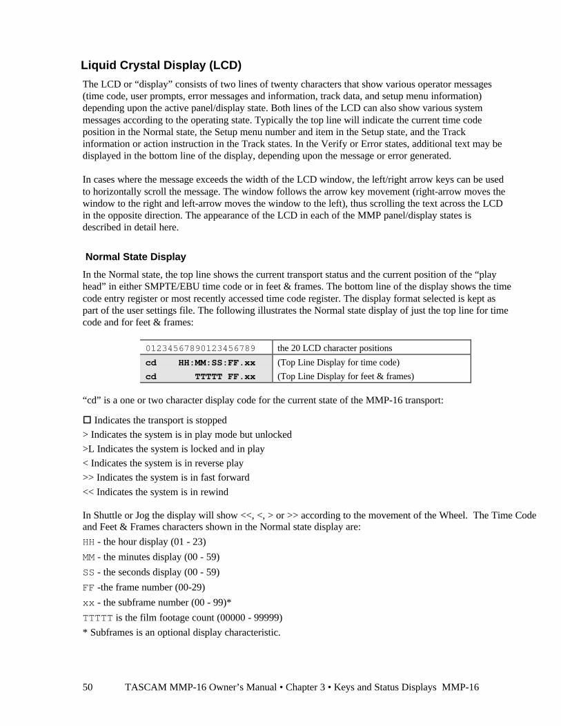
TASCAM MMP-16 Owner’s Manual • Chapter 3 • Keys and Status Displays MMP-1650
Liquid Crystal Display (LCD)
The LCD or “display” consists of two lines of twenty characters that show various operator messages(time code, user prompts, error messages and information, track data, and setup menu information)depending upon the active panel/display state. Both lines of the LCD can also show various systemmessages according to the operating state. Typically the top line will indicate the current time codeposition in the Normal state, the Setup menu number and item in the Setup state, and the Trackinformation or action instruction in the Track states. In the Verify or Error states, additional text may bedisplayed in the bottom line of the display, depending upon the message or error generated.
In cases where the message exceeds the width of the LCD window, the left/right arrow keys can be usedto horizontally scroll the message. The window follows the arrow key movement (right-arrow moves thewindow to the right and left-arrow moves the window to the left), thus scrolling the text across the LCDin the opposite direction. The appearance of the LCD in each of the MMP panel/display states isdescribed in detail here.
Normal State Display
In the Normal state, the top line shows the current transport status and the current position of the “playhead” in either SMPTE/EBU time code or in feet & frames. The bottom line of the display shows the timecode entry register or most recently accessed time code register. The display format selected is kept aspart of the user settings file. The following illustrates the Normal state display of just the top line for timecode and for feet & frames:
01234567890123456789 the 20 LCD character positions
cd HH:MM:SS:FF.xx (Top Line Display for time code)
cd TTTTT FF.xx (Top Line Display for feet & frames)
“cd” is a one or two character display code for the current state of the MMP-16 transport:
o Indicates the transport is stopped
> Indicates the system is in play mode but unlocked
>L Indicates the system is locked and in play
< Indicates the system is in reverse play
>> Indicates the system is in fast forward
<< Indicates the system is in rewind
In Shuttle or Jog the display will show <<, <, > or >> according to the movement of the Wheel. The Time Codeand Feet & Frames characters shown in the Normal state display are:
HH - the hour display (01 - 23)
MM - the minutes display (00 - 59)
SS - the seconds display (00 - 59)
FF -the frame number (00-29)
xx - the subframe number (00 - 99)*
TTTTT is the film footage count (00000 - 99999)
* Subframes is an optional display characteristic.

MMP-16 TASCAM MMP-16 Owner’s Manual • Chapter 3 • Keys and Status Displays 51
In the Normal state, the bottom line of the display shows time code (or feet & frames) that has beenentered manually, captured, or recalled from one of the memory or special-purpose registers. There is alabel in front of the time code (or feet & frames) to indicate what register is being displayed. The “Label”identifies the memory or register that is currently being displayed through these abbreviations: SYNC,OFST, RDR, TIME, FREE, HEAD, TAIL, IN, OUT, NEXT, PREV, and MEM n (where n = 0 - 9). If atime code is manually entered, or if CLR was pressed, there will be no listing in the “Label” area of thedisplay, indicating the timecode Entry register is displayed.
01234567890123456789 LCD character positions (left to right)
Label HH:MM:SS:FF.xx (Bottom Line Display for time code)
Label TTTTT FF.xx (Bottom Line Display for feet & frames)
Setup State Display
In the Setup state, the display is used to show a list of menus for setting various system parameters.Pressing the SETUP key enters this state. The top line shows the 3-digit menu number and the name ofthe menu. The bottom line shows the list of parameters. To scroll through the list of menus, use theUp/Down arrow keys or the wheel. You may also jump directly to “banks” of menus by pressing any ofthe numeric keys on the keypad. To scroll through the list of parameters for a selected menu, press TRIM,then use the Up/Down arrow keys or the Wheel. Note that the currently selected parameter will always bepreceded by a * character. Many parameters have system default values which can be accessed bypressing TRIM, followed by press SHIFT + CLR.
01234567890123456789 20 position LCD character positions
NNN Tttttttttttttttt Top: (NNN indicates the menu number, t indicates
the menu name)
*Tttttttttttttttttttt Bottom: (* indicates the currently selected
parameter, t indicates the parameter name)
To exit the Setup state and return to the Normal state, press SETUP, or press CLR, or press the EDIT,MON, or INPUT Track Mode keys. To jump directly to one of the Track states from the Setup state, pressVIEW TRACK, TRACK, or SLIP. Note that attempting to set the MMP to an invalid condition mayresult in an Error state, and that attempting to choose some menu parameters will put the system in theVerify state for confirmation of the choice before it is finalized.
View Track State Display
In the View Track state, the display is used to show the name of the selected track. To enter this state,press the TRACK key. Press the appropriate SEL key to display the desired track. The wheel and theUp/Down arrow keys can be used to move to the next or previous track selection.
01234567890123456789 LCD character positions (left to right)
Track Contents: Top: (Operator message)
T nnnnnnnnnnnnnnnnnn Bottom: (T indicates the assigned track, nnn is the track name
in the EDL) and will read *Blank* if the track isn’t assigned.
To exit the View Track state and return to the Normal state, press TRACK, or press CLR.
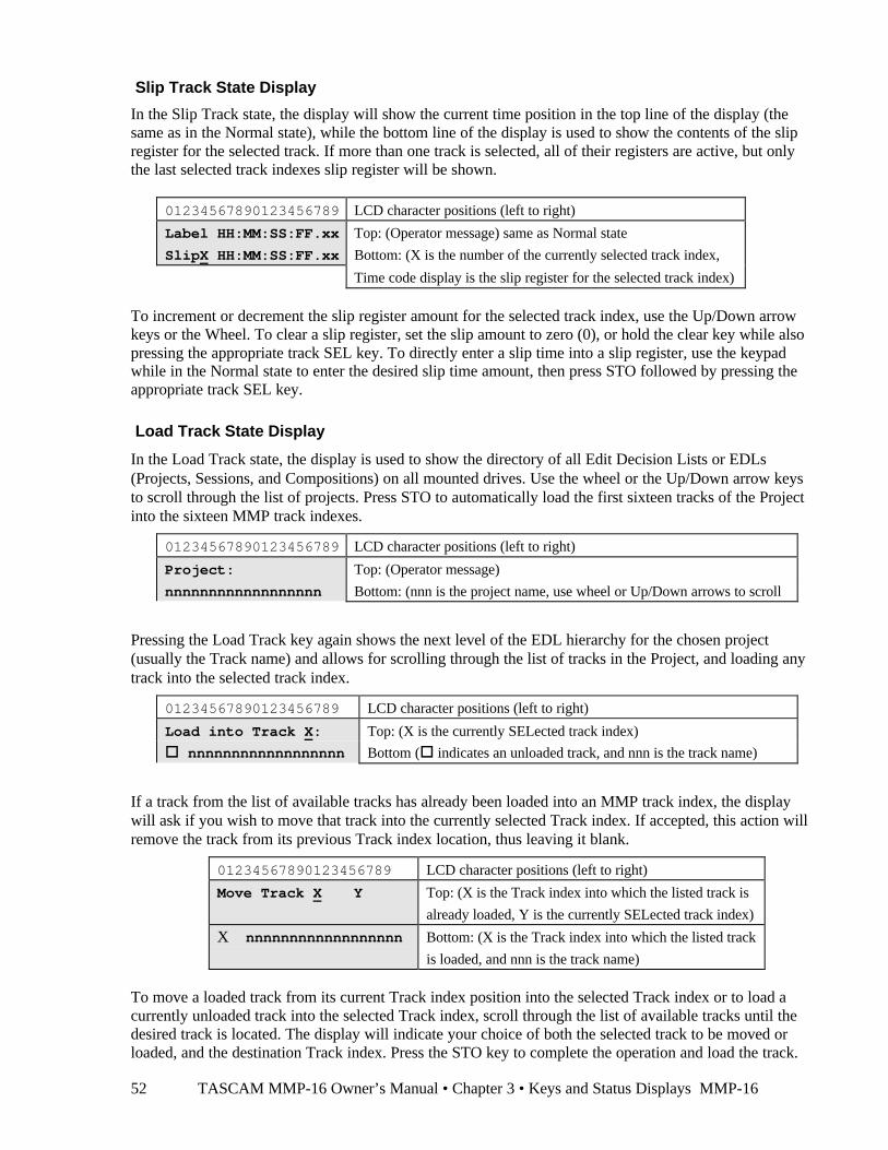
TASCAM MMP-16 Owner’s Manual • Chapter 3 • Keys and Status Displays MMP-1652
Slip Track State Display
In the Slip Track state, the display will show the current time position in the top line of the display (thesame as in the Normal state), while the bottom line of the display is used to show the contents of the slipregister for the selected track. If more than one track is selected, all of their registers are active, but onlythe last selected track indexes slip register will be shown.
01234567890123456789 LCD character positions (left to right)
Label HH:MM:SS:FF.xx Top: (Operator message) same as Normal state
SlipX HH:MM:SS:FF.xx Bottom: (X is the number of the currently selected track index,
Time code display is the slip register for the selected track index)
To increment or decrement the slip register amount for the selected track index, use the Up/Down arrowkeys or the Wheel. To clear a slip register, set the slip amount to zero (0), or hold the clear key while alsopressing the appropriate track SEL key. To directly enter a slip time into a slip register, use the keypadwhile in the Normal state to enter the desired slip time amount, then press STO followed by pressing theappropriate track SEL key.
Load Track State Display
In the Load Track state, the display is used to show the directory of all Edit Decision Lists or EDLs(Projects, Sessions, and Compositions) on all mounted drives. Use the wheel or the Up/Down arrow keysto scroll through the list of projects. Press STO to automatically load the first sixteen tracks of the Projectinto the sixteen MMP track indexes.
01234567890123456789 LCD character positions (left to right)
Project: Top: (Operator message)
nnnnnnnnnnnnnnnnnn Bottom: (nnn is the project name, use wheel or Up/Down arrows to scroll
Pressing the Load Track key again shows the next level of the EDL hierarchy for the chosen project(usually the Track name) and allows for scrolling through the list of tracks in the Project, and loading anytrack into the selected track index.
01234567890123456789 LCD character positions (left to right)
Load into Track X: Top: (X is the currently SELected track index)
o nnnnnnnnnnnnnnnnnn Bottom (o indicates an unloaded track, and nnn is the track name)
If a track from the list of available tracks has already been loaded into an MMP track index, the displaywill ask if you wish to move that track into the currently selected Track index. If accepted, this action willremove the track from its previous Track index location, thus leaving it blank.
01234567890123456789 LCD character positions (left to right)
Move Track X àà Y Top: (X is the Track index into which the listed track is
already loaded, Y is the currently SELected track index)
X nnnnnnnnnnnnnnnnnn Bottom: (X is the Track index into which the listed track
is loaded, and nnn is the track name)
To move a loaded track from its current Track index position into the selected Track index or to load acurrently unloaded track into the selected Track index, scroll through the list of available tracks until thedesired track is located. The display will indicate your choice of both the selected track to be moved orloaded, and the destination Track index. Press the STO key to complete the operation and load the track.
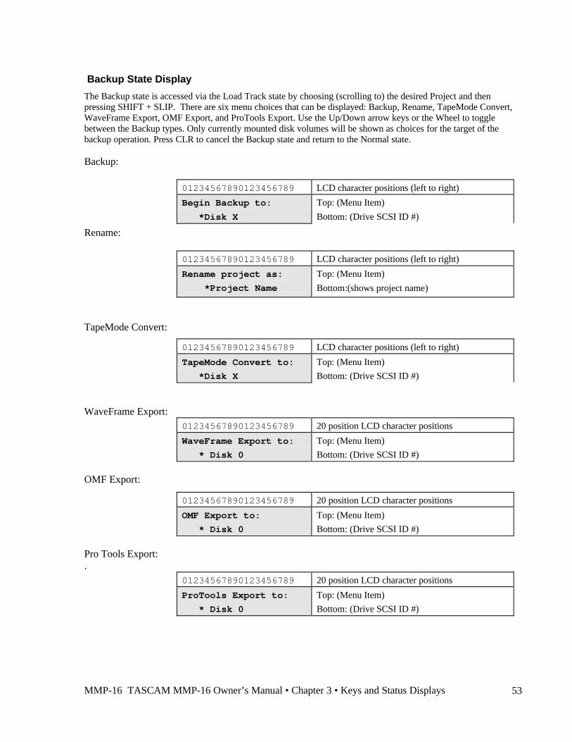
MMP-16 TASCAM MMP-16 Owner’s Manual • Chapter 3 • Keys and Status Displays 53
Backup State Display
The Backup state is accessed via the Load Track state by choosing (scrolling to) the desired Project and thenpressing SHIFT + SLIP. There are six menu choices that can be displayed: Backup, Rename, TapeMode Convert,WaveFrame Export, OMF Export, and ProTools Export. Use the Up/Down arrow keys or the Wheel to togglebetween the Backup types. Only currently mounted disk volumes will be shown as choices for the target of thebackup operation. Press CLR to cancel the Backup state and return to the Normal state.
Backup:
01234567890123456789 LCD character positions (left to right)
Begin Backup to: Top: (Menu Item)
*Disk X Bottom: (Drive SCSI ID #)
Rename:
01234567890123456789 LCD character positions (left to right)
Rename project as: Top: (Menu Item)
*Project Name Bottom:(shows project name)
TapeMode Convert:
01234567890123456789 LCD character positions (left to right)
TapeMode Convert to: Top: (Menu Item)
*Disk X Bottom: (Drive SCSI ID #)
WaveFrame Export:01234567890123456789 20 position LCD character positions
WaveFrame Export to: Top: (Menu Item)
* Disk 0 Bottom: (Drive SCSI ID #)
OMF Export:
01234567890123456789 20 position LCD character positions
OMF Export to: Top: (Menu Item)
* Disk 0 Bottom: (Drive SCSI ID #)
Pro Tools Export:.
01234567890123456789 20 position LCD character positions
ProTools Export to: Top: (Menu Item)
* Disk 0 Bottom: (Drive SCSI ID #)
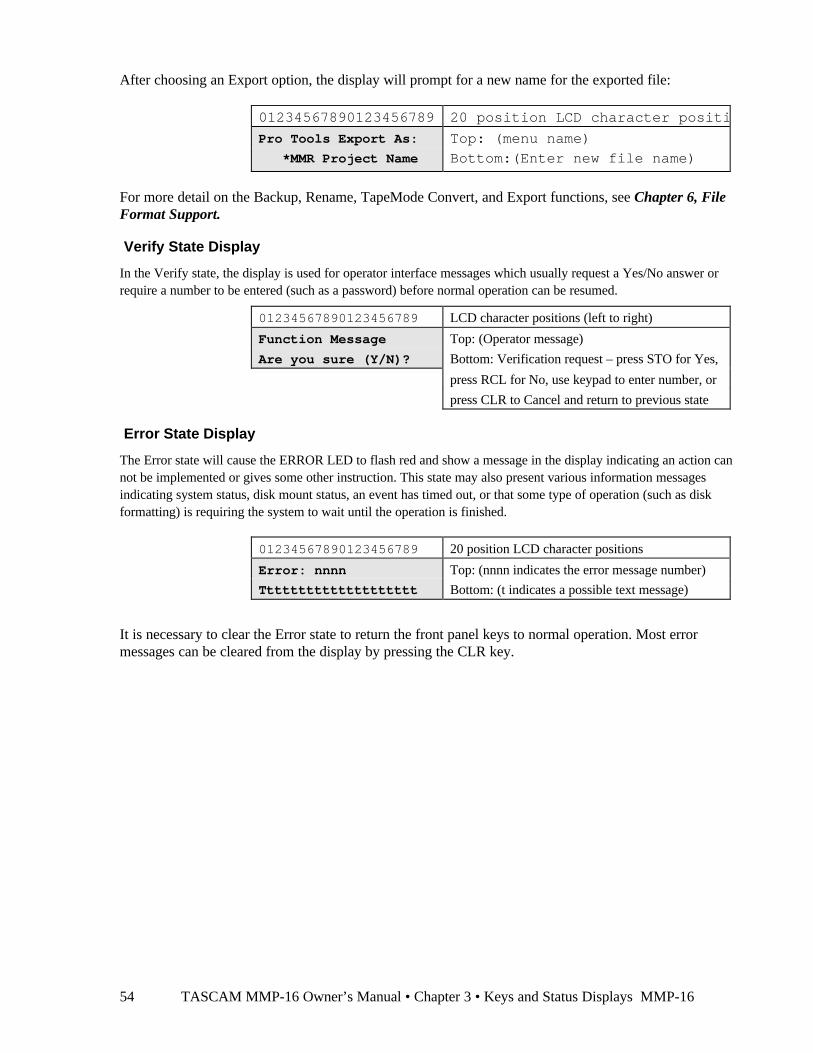
TASCAM MMP-16 Owner’s Manual • Chapter 3 • Keys and Status Displays MMP-1654
After choosing an Export option, the display will prompt for a new name for the exported file:
01234567890123456789 20 position LCD character positions
Pro Tools Export As: Top: (menu name)
*MMR Project Name Bottom:(Enter new file name)
For more detail on the Backup, Rename, TapeMode Convert, and Export functions, see Chapter 6, FileFormat Support.
Verify State Display
In the Verify state, the display is used for operator interface messages which usually request a Yes/No answer orrequire a number to be entered (such as a password) before normal operation can be resumed.
01234567890123456789 LCD character positions (left to right)
Function Message Top: (Operator message)
Are you sure (Y/N)? Bottom: Verification request – press STO for Yes,
press RCL for No, use keypad to enter number, or
press CLR to Cancel and return to previous state
Error State Display
The Error state will cause the ERROR LED to flash red and show a message in the display indicating an action cannot be implemented or gives some other instruction. This state may also present various information messagesindicating system status, disk mount status, an event has timed out, or that some type of operation (such as diskformatting) is requiring the system to wait until the operation is finished.
01234567890123456789 20 position LCD character positions
Error: nnnn Top: (nnnn indicates the error message number)
Tttttttttttttttttttt Bottom: (t indicates a possible text message)
It is necessary to clear the Error state to return the front panel keys to normal operation. Most errormessages can be cleared from the display by pressing the CLR key.
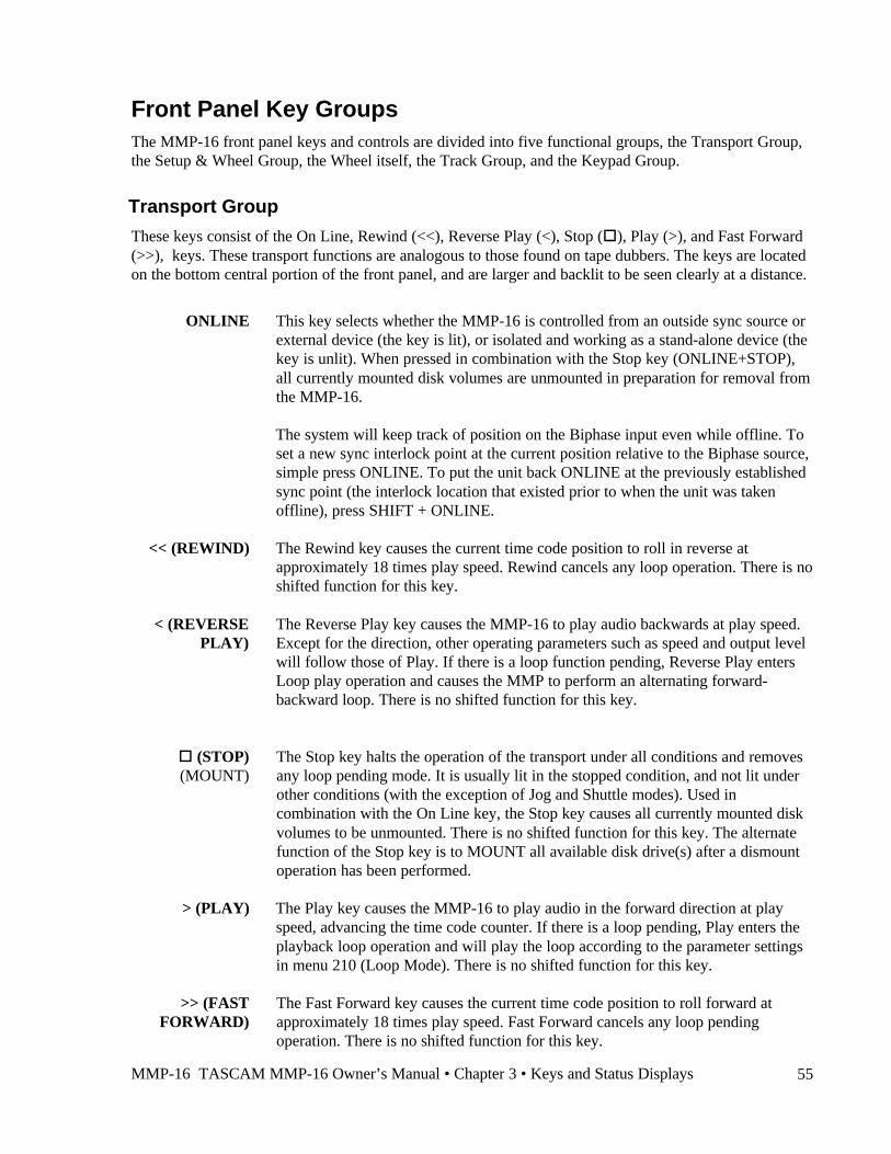
MMP-16 TASCAM MMP-16 Owner’s Manual • Chapter 3 • Keys and Status Displays 55
Front Panel Key GroupsThe MMP-16 front panel keys and controls are divided into five functional groups, the Transport Group,the Setup & Wheel Group, the Wheel itself, the Track Group, and the Keypad Group.
Transport Group
These keys consist of the On Line, Rewind (<<), Reverse Play (<), Stop (o), Play (>), and Fast Forward(>>), keys. These transport functions are analogous to those found on tape dubbers. The keys are locatedon the bottom central portion of the front panel, and are larger and backlit to be seen clearly at a distance.
ONLINE This key selects whether the MMP-16 is controlled from an outside sync source orexternal device (the key is lit), or isolated and working as a stand-alone device (thekey is unlit). When pressed in combination with the Stop key (ONLINE+STOP),all currently mounted disk volumes are unmounted in preparation for removal fromthe MMP-16.
The system will keep track of position on the Biphase input even while offline. Toset a new sync interlock point at the current position relative to the Biphase source,simple press ONLINE. To put the unit back ONLINE at the previously establishedsync point (the interlock location that existed prior to when the unit was takenoffline), press SHIFT + ONLINE.
<< (REWIND) The Rewind key causes the current time code position to roll in reverse atapproximately 18 times play speed. Rewind cancels any loop operation. There is noshifted function for this key.
< (REVERSEPLAY)
The Reverse Play key causes the MMP-16 to play audio backwards at play speed.Except for the direction, other operating parameters such as speed and output levelwill follow those of Play. If there is a loop function pending, Reverse Play entersLoop play operation and causes the MMP to perform an alternating forward-backward loop. There is no shifted function for this key.
o (STOP)(MOUNT)
The Stop key halts the operation of the transport under all conditions and removesany loop pending mode. It is usually lit in the stopped condition, and not lit underother conditions (with the exception of Jog and Shuttle modes). Used incombination with the On Line key, the Stop key causes all currently mounted diskvolumes to be unmounted. There is no shifted function for this key. The alternatefunction of the Stop key is to MOUNT all available disk drive(s) after a dismountoperation has been performed.
> (PLAY) The Play key causes the MMP-16 to play audio in the forward direction at playspeed, advancing the time code counter. If there is a loop pending, Play enters theplayback loop operation and will play the loop according to the parameter settingsin menu 210 (Loop Mode). There is no shifted function for this key.
>> (FASTFORWARD)
The Fast Forward key causes the current time code position to roll forward atapproximately 18 times play speed. Fast Forward cancels any loop pendingoperation. There is no shifted function for this key.
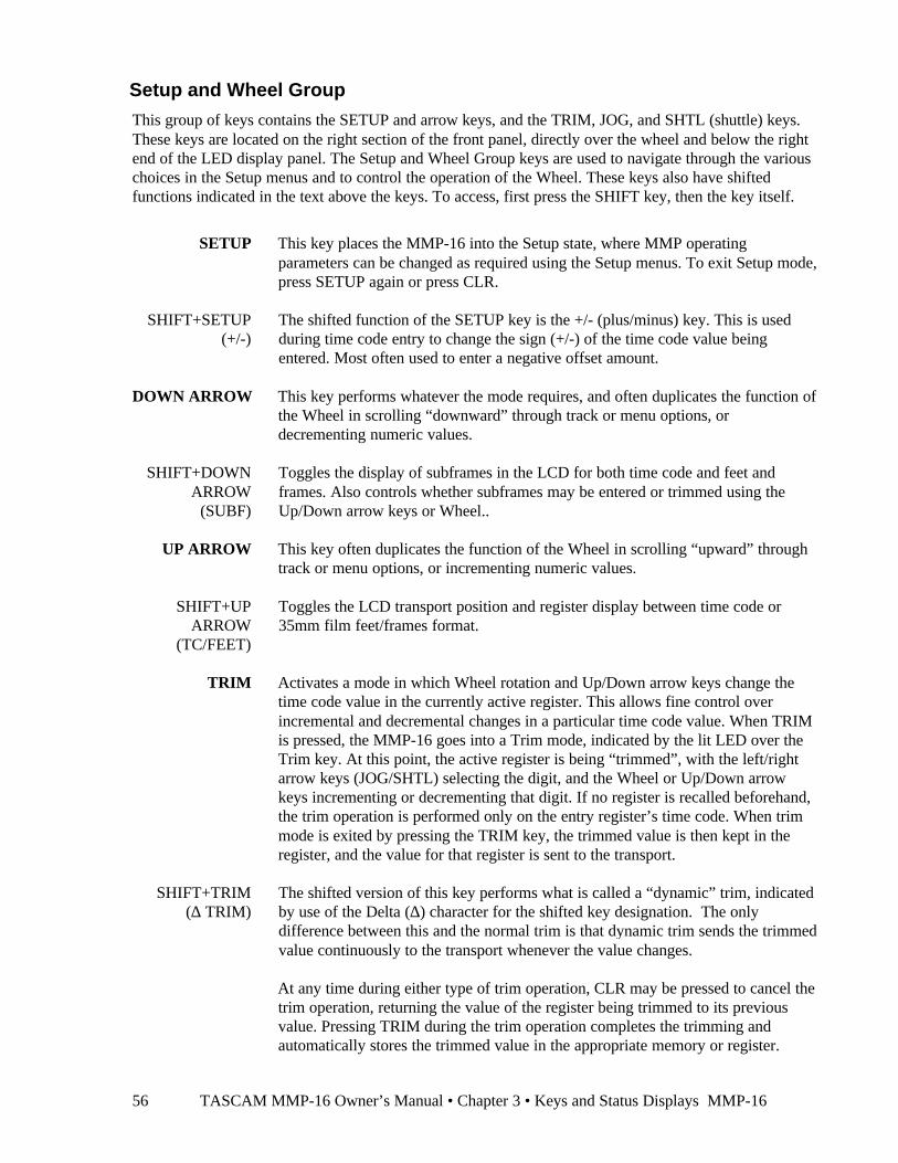
TASCAM MMP-16 Owner’s Manual • Chapter 3 • Keys and Status Displays MMP-1656
Setup and Wheel Group
This group of keys contains the SETUP and arrow keys, and the TRIM, JOG, and SHTL (shuttle) keys.These keys are located on the right section of the front panel, directly over the wheel and below the rightend of the LED display panel. The Setup and Wheel Group keys are used to navigate through the variouschoices in the Setup menus and to control the operation of the Wheel. These keys also have shiftedfunctions indicated in the text above the keys. To access, first press the SHIFT key, then the key itself.
SETUP This key places the MMP-16 into the Setup state, where MMP operatingparameters can be changed as required using the Setup menus. To exit Setup mode,press SETUP again or press CLR.
SHIFT+SETUP(+/-)
The shifted function of the SETUP key is the +/- (plus/minus) key. This is usedduring time code entry to change the sign (+/-) of the time code value beingentered. Most often used to enter a negative offset amount.
DOWN ARROW This key performs whatever the mode requires, and often duplicates the function ofthe Wheel in scrolling “downward” through track or menu options, ordecrementing numeric values.
SHIFT+DOWNARROW
(SUBF)
Toggles the display of subframes in the LCD for both time code and feet andframes. Also controls whether subframes may be entered or trimmed using theUp/Down arrow keys or Wheel..
UP ARROW This key often duplicates the function of the Wheel in scrolling “upward” throughtrack or menu options, or incrementing numeric values.
SHIFT+UPARROW
(TC/FEET)
Toggles the LCD transport position and register display between time code or35mm film feet/frames format.
TRIM Activates a mode in which Wheel rotation and Up/Down arrow keys change thetime code value in the currently active register. This allows fine control overincremental and decremental changes in a particular time code value. When TRIMis pressed, the MMP-16 goes into a Trim mode, indicated by the lit LED over theTrim key. At this point, the active register is being “trimmed”, with the left/rightarrow keys (JOG/SHTL) selecting the digit, and the Wheel or Up/Down arrowkeys incrementing or decrementing that digit. If no register is recalled beforehand,the trim operation is performed only on the entry register’s time code. When trimmode is exited by pressing the TRIM key, the trimmed value is then kept in theregister, and the value for that register is sent to the transport.
SHIFT+TRIM(∆ TRIM)
The shifted version of this key performs what is called a “dynamic” trim, indicatedby use of the Delta (∆) character for the shifted key designation. The onlydifference between this and the normal trim is that dynamic trim sends the trimmedvalue continuously to the transport whenever the value changes.
At any time during either type of trim operation, CLR may be pressed to cancel thetrim operation, returning the value of the register being trimmed to its previousvalue. Pressing TRIM during the trim operation completes the trimming andautomatically stores the trimmed value in the appropriate memory or register.
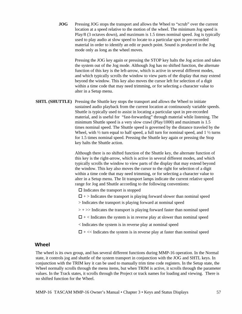
MMP-16 TASCAM MMP-16 Owner’s Manual • Chapter 3 • Keys and Status Displays 57
JOG Pressing JOG stops the transport and allows the Wheel to “scrub” over the currentlocation at a speed relative to the motion of the wheel. The minimum Jog speed isPlay/8 (3 octaves down), and maximum is 1.5 times nominal speed. Jog is typicallyused to play audio at slow speed to locate to a particular spot in pre-recordedmaterial in order to identify an edit or punch point. Sound is produced in the Jogmode only as long as the wheel moves.
Pressing the JOG key again or pressing the STOP key halts the Jog action and takesthe system out of the Jog mode. Although Jog has no shifted function, the alternatefunction of this key is the left-arrow, which is active in several different modes,and which typically scrolls the window to view parts of the display that may extendbeyond the window. This key also moves the cursor left for selection of a digitwithin a time code that may need trimming, or for selecting a character value toalter in a Setup menu.
SHTL (SHUTTLE) Pressing the Shuttle key stops the transport and allows the Wheel to initiatesustained audio playback from the current location at continuously variable speeds.Shuttle is typically used to assist in locating a particular spot in pre-recordedmaterial, and is useful for “fast-forwarding” through material while listening. Theminimum Shuttle speed is a very slow crawl (Play/1000) and maximum is 1.5times nominal speed. The Shuttle speed is governed by the distance traveled by theWheel, with ½ turn equal to half speed, a full turn for nominal speed, and 1 ½ turnsfor 1.5 times nominal speed. Pressing the Shuttle key again or pressing the Stopkey halts the Shuttle action.
Although there is no shifted function of the Shuttle key, the alternate function ofthis key is the right-arrow, which is active in several different modes, and whichtypically scrolls the window to view parts of the display that may extend beyondthe window. This key also moves the cursor to the right for selection of a digitwithin a time code that may need trimming, or for selecting a character value toalter in a Setup menu. The lit transport lamps indicate the current relative speedrange for Jog and Shuttle according to the following conventions:
o Indicates the transport is stopped
o + > Indicates the transport is playing forward slower than nominal speed
> Indicates the transport is playing forward at nominal speed
> + >> Indicates the transport is playing forward faster than nominal speed
o + < Indicates the system is in reverse play at slower than nominal speed
< Indicates the system is in reverse play at nominal speed
o + << Indicates the system is in reverse play at faster than nominal speed
Wheel
The wheel is its own group, and has several different functions during MMP-16 operation. In the Normalstate, it controls jog and shuttle of the system transport in conjunction with the JOG and SHTL keys. Inconjunction with the TRIM key it can be used to manually trim time code registers. In the Setup state, theWheel normally scrolls through the menu items, but when TRIM is active, it scrolls through the parametervalues. In the Track states, it scrolls through the Project or track names for loading and viewing. There isno shifted function for the Wheel.
TASCAM MMP-16 Owner’s Manual • Chapter 3 • Keys and Status Displays MMP-1658
Track Group
These keys are located at the left central portion of the front panel under the track meters. Although theSEL keys are active all the time, they affect tracks according to which Track Select Mode (EDIT, MON,LOAD TRACK, TRACK, SLIP) is active. The active mode is indicated by the amber LED above thekeys, while the active track(s) for that mode are indicated by the amber LEDs above the SEL keys.
SEL(TRACK
SELECT)
The sixteen gray SEL keys are located just below their associated meter displayLEDs. These keys are normally used to select and deselect their associated tracks,although they do have track independent shifted functions as well (as indicated bythe labels above each SEL key: Cut, Copy, Clear, etc.).
When EDIT or MON is active (as one will always be while in the Normal state),the SEL keys choose which tracks are edited (when EDIT is active), or monitoredat the headphone jack (when MON is active). The chosen tracks for each functionare indicated through the amber LEDs above each SEL key. The chosen tracks are“remembered” by the MMP-16. Thus as EDIT or MON is pressed, the amber SELindicators change to reflect the selected tracks for each function.
When loading individual tracks in the Load Track state (after pressing LOADTRACK twice), the Track Select keys allow the selection of the “target” track—theMMP track index to which a stored track file will be loaded or moved. Only onetrack at a time may be selected in this mode. When viewing tracks in the Trackstate (TRACK key is active), only one track can be viewed at a time as indicatedby the amber LED above the SEL key (the Wheel and arrow keys are active in thismode, scrolling and selecting one track at a time).
When slipping tracks in the Track Slip state (SLIP is active), multiple tracks maybe selected as “targets” for a slip operation. However, only the last selected track isdisplayed on the bottom line of the LCD. A slip value may be entered manuallyinto the entry register, or recalled from one of the memories or registers. It is thenstored into the selected track by pressing STO followed by the appropriate SELkey. Slipped tracks (NOT tracks selected for slipping) are identified by an LED onthe bottom row of the meter panel, regardless of the operating mode of the MMP-16. Press CLR+SEL to clear the slip register for any track and return it to an un-slipped status.
SHIFT+SEL(various EDIT
commands)
When shifted (SHIFT+SEL), the Track Select keys perform various edit operationson those tracks previously selected while the EDIT key was active. Editing iscontrolled by the In point and Out point times from the In and Out registers. Notethat the In and Out registers can be automatically set to the start and end times ofany event by placing the play head within the event and pressing SHIFT+EDIT.
MMP-16 TASCAM MMP-16 Owner’s Manual • Chapter 3 • Keys and Status Displays 59
SHIFT+EDIT(EVENT)
Loads the start and end of the event currently under the play head on the selectedtrack(s) into the In point and Out point registers (also called “event capture”).
MON Pressing this key while in the Normal state allows the SEL keys to select whichtrack(s) will be monitored through the front panel headphone monitor output. Thisdoes not affect the rear panel Studio Monitor jack, which always presents a monomix of all tracks.
SHIFT+MON(Slip In/Out)
Pressing SHIFT + MON puts the MMP into a Slip In/Out mode that allows forslipping (or nudging) all material between the In and Out register locations onselected tracks. When Slip In/Out is active, none of the status LEDs for the TrackMode Select keys is lit on the MMP front panel. This is to distinguish this modefrom all other Track Select Modes, wherein at least one Track Select Mode statusLED is always lit. Upon pressing SHIFT + MON, the bottom line of the displaywill show Slip and a time code entry field. Use the Wheel or the Up/Down arrowkeys to enter the amount by which the defined region (between In and Out) on theselected tracks is to be slipped. This operation does not affect sync on materialwhich is not located between the In and Out register locations. Slip In/Out willoverwrite any existing material on the selected tracks that is at the new destinationlocation to which the material has been moved.
To complete the Slip In/Out operation, press SHIFT +MON again. The bottom lineof the display will show Slip In/Out to indicate that the slip operation has beenperformed. To exit the Slip In/Out operation without executing the slip, press CLR.
LOAD TRACK Pressing this key puts the MMP-16 into the Load Track state, and is the first step toloading pre-recorded material for playback or for deleting recorded material.Information on the pre-recorded material available on the drive is presented inhierarchical levels on the LCD display, according to the EDL format of thematerial itself.
For WaveFrame or StudioFrame volumes, this means the material will be listedin a Project / Episode / Reel / Dub / Track hierarchy, with Episode being anoptional element. For Pro Tools volumes, the material will be listed in Session /Track hierarchy, and for OMF volumes, the material will be presented in aComposition / Track hierarchy.
As with the Setup menu system, the Wheel and arrow keys are used to navigatethrough the available selections at a given level. Unlike the Setup menu system,however, descending through the hierarchy of track information is accomplishedby repeatedly pressing LOAD TRACK. Pressing LOAD TRACK while at thebottom or “track” level exits the Load Track state and returns the MMP-16 to theNormal state.
TASCAM MMP-16 Owner’s Manual • Chapter 3 • Keys and Status Displays MMP-1660
When LOAD TRACK is first pressed, the LCD will show a list of all WaveFrameProjects, Pro Tools Sessions, or OMF Compositions on all mounted volumes. Thewheel or arrow keys are used to scroll through the various choices (if multiplechoices are available) and to display the name of each of the available files. Toview the next lower level of the EDL hierarchy (Episode, Reel, Act, Dub or Track),for the currently displayed Project, Session, or Composition, press LOAD TRACKagain. Repeat this procedure to reach the lowest level available for the particularEDL file type. Pro Tools Session files and OMF Compositions will exhibit onlytwo levels – the main EDL (Session or Composition) and Track.
Once the desired Project or track is located and displayed, press the Store (STO)key to load the Project (up to sixteen tracks) or individual track into the MMPTrack index locations. The target Track index is designated by activating the SELkey associated with the Track index (the LED above the SEL will be lit when theTrack index is chosen as a target). If a track listed in the display has already beenloaded into a track index, the display message will read “Move” rather than“Load”. This allows you to move an already loaded track into a different trackindex. Which operation is performed depends upon whether the source track file isalready loaded; if it is, then a track move is performed. If the source track file is notalready loaded, a track load is performed and the track file is loaded or “stored”into the target track. If track information is stored into a track location that isalready occupied by a previously loaded track, the previously loaded track isautomatically “unloaded.” In Load Track mode, the bottom line of the LCD showsthe names of “unloaded” tracks preceded by a small box (the STOP character) inthe first character of the display. Loaded tracks are preceded by their track number(indicating the track into which the sound file has been loaded).
The last target track (which defaults to Track 1 at the start of a session) isremembered for the duration of the session. A store operation (either load or move)automatically advances the target track by one, circularly advancing back to trackone after track sixteen. The target track may be selected manually by pressing theappropriate SEL key before STO is pressed. The Load Track key is also used toidentify Projects or Tracks for Backup. Choose (scroll to) the name of the desiredProject or Track, then press SHIFT + SLIP to enter the Backup state.
SHIFT + LOADTRACK
(DELETE)
Pressing SHIFT + LOAD TRACK deletes the currently displayed project or trackfile. The deletion simply removes the EDL information, not the associated soundfile(s), so little disk drive space is reclaimed by this operation. However, soundfiles not associated with the EDL (track) information are made available fordeletion by the Disk Cleanup operation accessed via Setup menu 720. This is thetypical method by which space on a given drive volume is reclaimed (the othermethod is by using Destructive Record on a TASCAM MMR-8 Recorder to recordover existing material).
TRACK Pressing this key places the MMP into the View Track state to allow inspection ofthe currently loaded tracks. The Wheel, the Select keys, or the Up/Down arrowkeys may be used to select and view a track index. If nothing is loaded in aselected Track index, the word “*Blank*” is displayed for that track. Pressing thiskey again while viewing tracks or pressing the CLR key exits the View Track stateand returns the MMP-16 to the Normal state.
MMP-16 TASCAM MMP-16 Owner’s Manual • Chapter 3 • Keys and Status Displays 61
SHIFT+TRACK(UNLOAD)
The shifted function of the TRACK key allows “unloading” of a loaded track, andwill return the track to the “blank” state, as well as returning the loaded track backto the pool of unloaded tracks, which can then be viewed using LOAD TRACK.
Note that tracks may be loaded or unloaded even while the MMP is playing. This isa very convenient feature of the MMP and allows for auditioning alternate tracksduring playback or loading tracks from different projects.
SLIP Pressing this key allows the re-positioning of selected tracks relative to the timelineand other tracks. The LCD will show the number of the last selected track,although all selected tracks (as indicated by the LEDs above the SEL keys) will be“slipped” as a group. Once the tracks to be slipped have been selected, the wheel orarrow keys are used to trim the slip value. The slip register for each track will beadjusted by the relative amount entered during the slip operation. In other words, ifa track is already slipped by 10 frames and it is then made part of a group of trackswhich are slipped by two more frames, that track’s slip register will then show avalue of 12 frames. The MMP-16 will “remember” the slipped tracks (as indicatedby the SLIP LEDs below the meters) and the slip value for a given session, so anyslip value must be explicitly removed in order to clear the slip register for thattrack. To clear the Slip register, either use the Wheel or Up/Down arrow keys to setthe Slip value to 0, or press CLR + SEL for the desired track. Note that the value inthe slip register is volatile, and will not be retained when the track index isunloaded or replaced by a different track. To slip a track permanently within theEDL, perform an Edit operation (Clear and Paste the contents of the entire track),or use the Slip In/Out function described under SHIFT + MON.
SHIFT + SLIP(BACKUP)
Pressing SHIFT+SLIP places the MMP into the Backup state so that a backup copyof the currently displayed project or track can be made to any mounted drivevolume. The Backup state presents three menu items that allow for choosing eithernormal, Tape Mode, or OMF Export style backup. Use the Wheel or Up/Downarrow keys to switch between these three menus after entering the Backup state.
Normal backup will copy the project or track file including all edit information andassociated audio clips to the target drive. The Tape Mode backup will rewrite(copy) the project or track files as continuous media files with no audio edits, andall fades fully rendered. Tape Mode backup will copy only media actually used inthe project or track, and provides a way to consolidate the data and “flatten” the filefor more efficient playback and disk usage. The word _TAPE will be appended tothe end of the file name of the newly created tape mode backup file so that it can bedistinguished from the original file name. This is especially important if the backupis made to the same disk as the original file. The OMF Export option will write outall media files and the EDL to any Macintosh formatted disk. The audio files willbe converted to Sound Designer II format, and the EDL will be written as an OMFcomposition referencing the Sound Designer II media. When not in the Load Trackstate, pressing SHIFT + SLIP will display the current status (progress) of theBackup function.

TASCAM MMP-16 Owner’s Manual • Chapter 3 • Keys and Status Displays MMP-1662
Keypad Group
These keys are located in the central portion of the front panel, directly under the LCD. In addition to thenumeric keys 0-9 (which are mainly used to enter and otherwise manipulate time code), keys performingvarious other operations are also located here:
• (CLR) the clear time code key• (CAPT) time code capture key• SHIFT key• (STO) store key• (RCL) recall key• (LOOP) looping key• (LOC) locate transport key
NUMERIC KEYS(0-9) In the Normal state, these keys are used to enter a time code value into the hold
register (the bottom line of the LCD). The numeric keys are also used to access tentime code memory registers and in combination with the SHIFT, RCL, STO,LOOP and LOC keys to store or recall time code to and from the various specialtime code registers. In the Setup state, these keys directly select menu banks, andare used to enter passwords, date, time, and other numeric entry. The Error andTrack states may also use these keys to enter a password or other numeric value.
Time code values are entered into the entry register, beginning with the right-handdigit which moves left as additional digits are entered. Use CLR to reset the entryregister to zero {00:00:00,00}. As an example of the entry register’s use; toenter a time code of 00:34:00,15 (thirty-four minutes and 15 frames); pressCLR one or two times (to set the entry register to zero), then the 3 (three) key,4 (four) key, 0 (zero) key, 0 (zero) key, 1 (one) key, and 5 (five) key. The timecode is displayed as the numbers are keyed into the hold register.
To store the entry register time code into one of the ten memory registers, pressSTO followed by one of the numeric keys. This stores the entry register time codeinto the selected memory register (0 - 9). The stored time code can later be recalledby pressing RCL then the appropriate numeric key. The entry register time can alsobe stored to the special-purpose registers that are not display-only (Lynx Sync,Offset, Time, Out, In), replacing the previous register contents. In this case the shiftkey is added to the store command key sequence (STO then SHIFT+ theappropriate numeric key).
SHIFT+NUMERIC KEY
The shifted function for each numeric key recalls the special-purpose registercontents listed above each numeric key, and for certain registers (the registersassociated with keys 0, 4, 5, 6, 7, 8, or 9) performs an immediate transport locate tothe register time code value. If STO is pressed before SHIFT+ one of the numerickeys is pressed, then the active register contents (bottom line of the display) arestored in the target register location (providing, of course, that the target register isa writeable and not a read-only register).
LYNX SYNC(SHIFT+0)
This register holds the MMP-16 sync point time which is used in conjunctionwith the master sync point on the Lynx bus to calculate the MMP-16 offset.Storing a value to this register automatically calculates this offset.
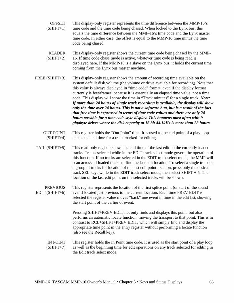
MMP-16 TASCAM MMP-16 Owner’s Manual • Chapter 3 • Keys and Status Displays 63
OFFSET(SHIFT+1)
This display-only register represents the time difference between the MMP-16’stime code and the time code being chased. When locked to the Lynx bus, thisequals the time difference between the MMP-16’s time code and the Lynx mastertime code. In either case, the offset is equal to the MMP-16 time minus the timecode being chased.
READER(SHIFT+2)
This display-only register shows the current time code being chased by the MMP-16. If time code chase mode is active, whatever time code is being read isdisplayed here. If the MMP-16 is a slave on the Lynx bus, it holds the current timecoming from the Lynx bus master machine.
FREE (SHIFT+3) This display-only register shows the amount of recording time available on thesystem default disk volume (the volume or drive available for recording). Note thatthis value is always displayed in “time code” format, even if the display formatcurrently is feet/frames, because it is essentially an elapsed time value, not a timecode. This display will show the time in “Track minutes” for a single track. Note:If more than 24 hours of single track recording is available, the display will showonly the time over 24 hours. This is not a software bug, but is a result of the factthat free time is expressed in terms of time code values and there are only 24hours possible for a time code style display. This happens most often with 9gigabyte drives where the disk capacity at 16 bit 44.1kHz is more than 28 hours.
OUT POINT(SHIFT+4)
This register holds the “Out Point” time. It is used as the end point of a play loopand as the end time for a track marked for editing.
TAIL (SHIFT+5) This read-only register shows the end time of the last edit on the currently loadedtracks. Tracks selected while in the EDIT track select mode govern the operation ofthis function. If no tracks are selected in the EDIT track select mode, the MMP willscan across all loaded tracks to find the last edit location. To select a single track ora group of tracks for location of the last edit point location, press only the desiredtrack SEL keys while in the EDIT track select mode, then select SHIFT + 5. Thelocation of the last edit point on the selected tracks will be shown.
PREVIOUSEDIT (SHIFT+6)
This register represents the location of the first splice point (or start of the soundevent) located just previous to the current location. Each time PREV EDIT isselected the register value moves “back” one event in time in the edit list, showingthe start point of the earlier of event.
Pressing SHIFT+PREV EDIT not only finds and displays this point, but alsoperforms an automatic locate function, moving the transport to that point. This is incontrast to RCL+SHIFT+PREV EDIT, which will simply find and display theappropriate time point in the entry register without performing a locate function(also see the Recall key).
IN POINT(SHIFT+7)
This register holds the In Point time code. It is used as the start point of a play loopas well as the beginning time for edit operations on any track selected for editing inthe Edit track select mode.

TASCAM MMP-16 Owner’s Manual • Chapter 3 • Keys and Status Displays MMP-1664
HEAD(SHIFT+8)
This read-only register shows the start time of the first edit on the currently loadedtracks. Tracks selected while in the EDIT track select mode govern the operation ofthis function. If no tracks are selected in the EDIT track select mode, the MMP willscan across all loaded tracks to find the first edit location. To select a single trackor a group of tracks for location of the first edit point location, press only thedesired track SEL keys while in the EDIT track select mode, then select SHIFT +8. The location of the first edit point on the selected tracks will be shown.
NEXT EDIT(SHIFT+9)
This register shows the location of the first splice point (or start of sound event)located just after the current location. Each time NEXT EDIT is selected theregister value moves “forward” one event in the edit list, always coming to rest atthe next splice point or start of event. Pressing SHIFT+NEXT EDIT not only findsand displays this point, but also performs an automatic locate function, moving thetransport to that point. RCL+SHIFT+NEXT EDIT simply finds and displays thenext edit time code in the hold register (also see the Recall key).
CLR This key performs both a clear and a cancel function, operating in almost all modesand situations. CLR has no shifted function.
In the Setup and Verify states, the CLR key takes on its alternate function,“cancel.” In Setup, pressing CLR generally returns a changed value back to thepreviously stored value, or exits altogether. It is also used to re-enter a password, tocancel a password entry, and as an alternative method of providing a “no” responseto an operator query. In the Error state, pressing CLR will clear the error messageand return the MMP-16 to the previous operating state. During track slip or registertrim, pressing the key returns the registers to their previous values (before the slipor trim operation changed them). During time code entry in the Normal state, CLRreturns the entry register time code to a zero value. For most other operations, CLRwill return the MMP-16 to the Normal state.
CAPT The capture key places the time code value from the top line of the display into theentry register in the bottom line of the display. After capturing the time code valuethe CAPT LED will flash until a target register key is pressed to place the capturedtime code value into that register. Note that pressing CAPT automatically readiesthe system to store the value into the target register, as if the STO key had alreadybeen pressed. This action can be done at any time during normal operation of theMMP-16 (including playback). To complete the capture operation, either press atarget register key or press CLR to cancel.
SHIFT + CAPT(TIME)
This register holds the Time code location that is set to be equal to 0 feet andframes. This is used in film post production work to set a “local 0” for interlockingfilm to a time code source. To set the offset between the time code display and thefeet and frames display, use the keypad to enter the time code that will beequivalent to 0 feet and frames into the entry register. Next, press LOC to locatethe MMP transport to that time and press CLR to clear the entry register. Finally,press STO + SHIFT + CAPT to enter the number listed in the top of the displayinto the TIME register. There will now be an offset between the time code displayand the feet and frames display when toggling between these two display styles. Toclear the time register, locate to 00:00:00:00 and store that to the Time register.
MMP-16 TASCAM MMP-16 Owner’s Manual • Chapter 3 • Keys and Status Displays 65
SHIFT The yellow SHIFT key functions like a locking keyboard shift key. When active, itmodifies those keys that have a shift function assigned to them (identified by thefunction name written above the gray keys). Pressing and releasing the yellow Shiftkey causes the shift LED to turn on, indicating SHIFT is active. Pressing a graykey with a shift function will then perform the shifted function and turn off theyellow Shift LED. To cancel Shift without pressing a function key, press SHIFTagain or press CLR (the shift LED will then turn off).
If multiple shifted keys are to be entered in a sequence, press and hold SHIFT (theshift LED will light) while pressing the various gray keys in sequence. When youlift your finger off SHIFT, the Shift function will be canceled (and the shift LEDwill turn off).
Use of the shift key is indicated in the text by SHIFT+X, where X indicates one ofthe gray keys. For example, pressing SHIFT+EDIT captures the in and out pointsof the current edit event, while pressing SHIFT+LOOP only cancels Shift (sinceLOOP has no shift function). All the various shifted functions are described in theappropriate key definitions. They are also listed in the Key Command Summary inAppendix A.
STO (STORE) The Store key is an important key, performing the functions of an enter orconfirmation key for various operations, as well as being a selection key for anactual store operation. Pressing STO + SEL will enter the current hold register timecode as a Slip amount for the selected track. In the Setup and Track states, itsalternate function is to answer “yes” to a Verify or Error state operator query.
In the Normal state, the store key is used to save the hold register value into anotherregister. To store a time code value into a register, press the STO key followed by anumeric key (to save the value to a memory register) or by the shift key and anumeric key (to save the value to a special-purpose register). In the Setup state,pressing STO selects the parameter value displayed in the LCD or undertakes anaction, according to the type of menu displayed. In the Verify state, the Store keyserves both to complete a password entry and to confirm a potentially destructiveaction. When loading projects or tracks (in the Load Track state), the Store keyinitiates the action of loading tracks into the MMP Track index locations. The LEDabove the Store key will flash when the key is pressed to begin a store operation,and will flash more quickly when pressing this key is a possible YES response to averify request or menu parameter selection. There is no shifted function for this key.
RCL (RECALL) This key is used to recall one of the time code registers, and to make it the “active”register. Pressing RCL+ a numeric key recalls one of the 10 system memoryregisters. Special-purpose register contents may also be accessed in this way throughusing RCL+SHIFT+ a numeric key. After a recall operation, the recalled value isdisplayed in the bottom line of the LCD. It is preceded with a four-charactermnemonic indicating the register that was recalled. The Recall key is also used toprovide a NO or negative response to a query when confirmation of a potentiallydestructive action is required. The LED above the Recall key will flash when the keyis pressed to begin a recall operation, and will flash more quickly when pressing thiskey is a possible NO response to a verify request or menu parameter selection. Thereis no shifted function for this key.
TASCAM MMP-16 Owner’s Manual • Chapter 3 • Keys and Status Displays MMP-1666
LOOP Pressing the Loop key prepares the MMP transport for performance of one ofseveral possible types of loop sequences relative to the In and Out time coderegisters. To start looping after LOOP is pressed and the In and Out times are set,press the appropriate transport key (<, >). To cancel Loop mode press LOOP againbefore pressing a transport key.
The start point of the loop is always the In register (minus any pre-roll time set)and the end point is the Out register (plus any post-roll time set). If the value of theOut register is less than (i.e., before) the value of the In point register, then the loopwill not play and an error message “Loop points inverted” will be displayed, sincethe In point value must always be considered the “start” point. The loop cannotplay across the “midnight crossing” at the 24 hour mark. This includes pre-roll orpost-roll amounts. There must be at least one frame between the 00:00:00:00 timecode location and the In minus pre-roll or Out plus post-roll times. There is noshifted function for this key.
There are three selectable Loop Play modes (Setup menu 210): Play Once andStop, Play Once and Cue, and Play Repeatedly. For Play Once and Stop, when play(>) is pressed after LOOP, the MMP-16 will loop from the In register time (minusany pre-roll amount) to the Out register time (plus any post-roll amount), and thenstop. For Play Once and Cue, when play (>) is pressed after LOOP, the MMP-16will loop from the In register time (minus any pre-roll amount) to the Out registertime (plus any post-roll amount), then cue to the In point minus pre-roll time. IfPlay Repeatedly is selected, the MMP-16 will play from the In time (minus anypre-roll amount) to the Out time (plus any post-roll amount), and repeat this sameplay sequence until STOP or LOOP is pressed again. The MMP does not execute aseamless repeat, so there will be a small gap in time between the end of the loopand beginning of the next iteration of the loop.
There are three selectable Loop Record modes (Setup menu 211): Record OnceOnly, Repeat Record, and Repeat w/Unload. Record Once Only will record only onthe first pass of the loop, and then switch to playback only for subsequent loops.Repeat Record will initiate a recording between the In and Out points for everyloop. Repeat w/Unload will make a recording on each pass and then unload thetrack just created by the record pass before the next loop begins. This allows forrapidly making many recordings in succession and keeping them all as separatesequentially numbered track files in the project.
Note: This menu and Menus 202: Record Key and Menu 203: Rehearse Keyexist in the MMP-16 to provide these settings for any MM-RC which may beattached to the MMP-16 as part of a larger system containing an MMR-8. TheMM-RC derives its settings for the Record, Rehearse, and Loop Record functionsfrom the unit to which it is attached (via the UI/B board), thus these menus arenecessary even though they do not have a function on the MMP-16 itself.
To perform a forward-backward loop, press Loop and then Reverse Play (<). TheMMP-16 will play forward from the start time (minus any pre-roll amount) to theend time (plus any post-roll amount) and then play in the reverse direction from theend time (plus any post-roll amount) to the start time (minus any pre-roll amount).The MMP will then continually repeat the process (according to the Loop Playmenu setting). Press STOP or LOOP to cancel Looping.
MMP-16 TASCAM MMP-16 Owner’s Manual • Chapter 3 • Keys and Status Displays 67
LOC (LOCATE) This key causes the transport to locate to the active register (bottom line of thedisplay) time code. The time code may be from a recalled register, a captured valueor a value entered through the numeric keypad. An implicit (or automatic) locate tocertain registers is done when a SHIFT+ numeric key is pressed. A locate operationalways stops the transport if it is not stopped. There is no shifted function for thiskey.
TASCAM MMP-16 Owner’s Manual • Chapter 4 • MMP-16 Operation MMP-1668
Chapter 4 MMP-16 Operation
Loading and Mounting DrivesThe MMP-16 will scan the SCSI bus when the system is powered up and will mount all available drives.Be sure that all drive bays holding removable drives contain fully-seated and engaged SCSI disk drivesthroughout the power-up process. Removable storage devices (such as the Nikon Beluga AV LIMDOWoptical drive) must be attached to the system SCSI bus when the system powers up. Removable storagedevices do not require that removable media disks be present at power up, as long as the device itself ispresent and turned on. Once the power up process is complete, drives in the removable Kingston carriersmay be “spun down” and removed from the MMP-16 following the unmount procedure, and later re-inserted and re-mounted using the mount procedure.
After this point, it is not necessary to turn off power to the MMP-16 if the internal removable hard driveneeds to be changed. “Hot swapping” is possible because the Kingston Drive Carrier features an integrallock/unlock key which removes power from the drive when in the unlock position. Before removing theinternal drive, always unmount the drives first (press STOP+ONLINE), before turning the drive key toremove power. DATA MAY BE LOST IF DRIVES ARE NOT UNMOUNTED BEFORE REMOVING.
HARD DRIVE NOTE:To prevent drive damage when moving hard drives, always allow plenty of time for thedrive heads to lock, and for the drive to spin down and stop, before removing the drive.
Once a new drive has been installed (simply press it into place, it only goes into the slot in one direction),move the key from the unlock position to the lock position. The drive will automatically spin up to speed.After allowing a few seconds for the drive to reach locked speed and release the heads, press the STOPkey. The MMP-16 will attempt to mount the drive. The “Mounting Volumes” message will be displayedon the LCD as the mount attempt begins. The MMP-16 will try for up to 30 seconds to find the first driveto mount. This is to allow time for the disk drive to spin up completely. After a successful re-mount (i.e.,not a power-up mount), the LCD will display the message “n Volumes Mounted”, where n is the numberof volumes mounted. If you receive the message “No Volumes Mounted”, press the STOP key again. Ifthe “No Volumes Mounted” message persists, re-seat, format, or replace the drive(s) as necessary untilthe mount succeeds. If the mount operation is attempted after all drives are already mounted, the message“No New Drives Mounted” will be shown.
If an unformatted drive is installed, or if the drive is not compatible with the system (i.e., is unreadable bythe MMP-16), then the MMP-16 will not be able to mount the volume. To initialize a volume, accessmenu item 710 (Disk Initialize), and press the STO (store) key. The LCD will display the message{Initialize Disk? }. If it’s a new hard drive, or you wish to fully erase and re-initialize a used drive,press STO (store) to continue. The message {Are you sure (y/n)?} then appears. If you wish to continue,press the STO (store) key again. If the drive is known to have information on it, and you wish to keep theinformation, answer no by pressing the RCL (Recall) key. Drives are initialized in WaveFrame format.
Once the drive has been initialized, it can be used on the MMP-16 or on a WaveFrame/StudioFramesystem for recording and playback. A low-level format may be accomplished in a similar fashion, usingmenu item 711 (Disk Low Format). Note that it will take quite some time to low-level format a disk, withthe amount of time dependent upon the size of the hard drive (e.g., for a 2 GB drive figure at least 30minutes). A low-level format is rarely needed, and should have been done by the drive manufacturer.
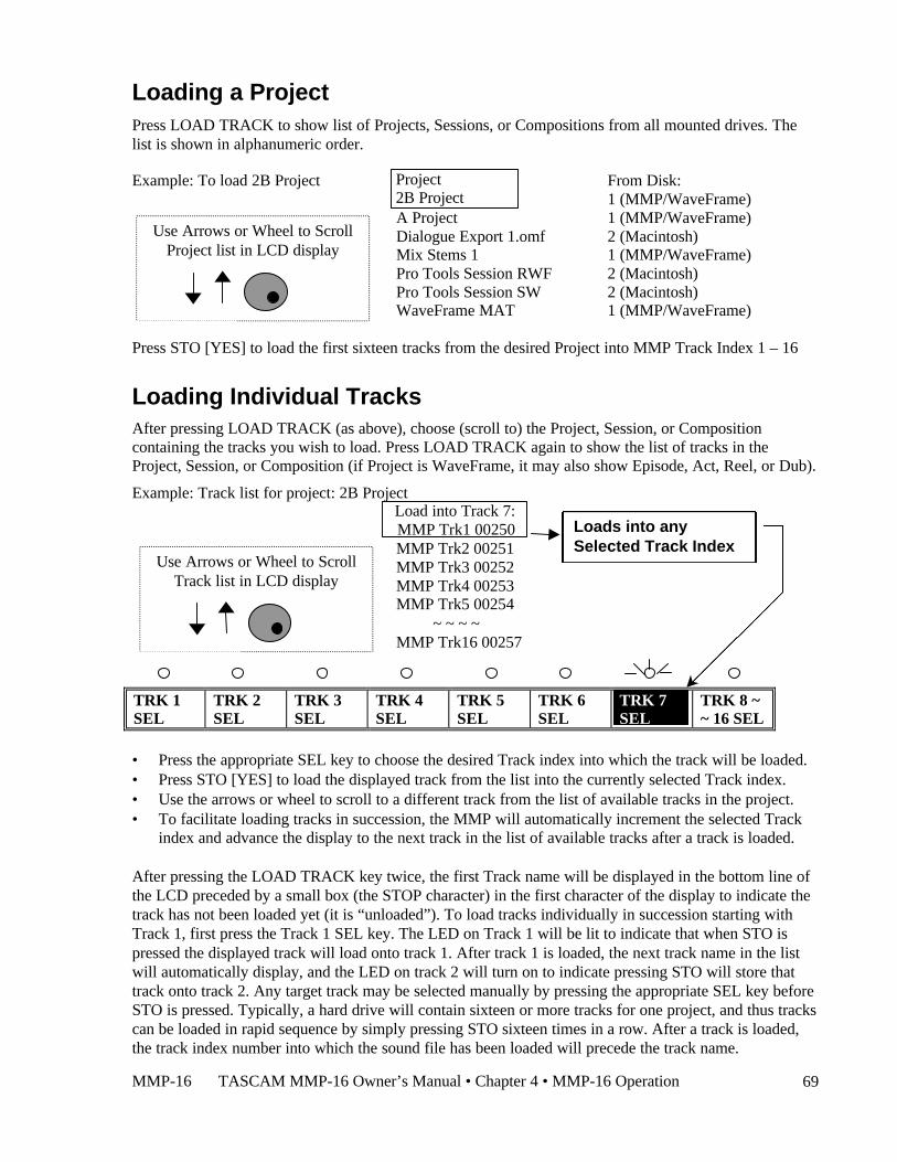
MMP-16 TASCAM MMP-16 Owner’s Manual • Chapter 4 • MMP-16 Operation 69
Loading a ProjectPress LOAD TRACK to show list of Projects, Sessions, or Compositions from all mounted drives. Thelist is shown in alphanumeric order.
Example: To load 2B Project From Disk:1 (MMP/WaveFrame)
A Project 1 (MMP/WaveFrame)Dialogue Export 1.omf 2 (Macintosh)Mix Stems 1 1 (MMP/WaveFrame)Pro Tools Session RWF 2 (Macintosh)Pro Tools Session SW 2 (Macintosh)WaveFrame MAT 1 (MMP/WaveFrame)
Press STO [YES] to load the first sixteen tracks from the desired Project into MMP Track Index 1 – 16
Loading Individual TracksAfter pressing LOAD TRACK (as above), choose (scroll to) the Project, Session, or Compositioncontaining the tracks you wish to load. Press LOAD TRACK again to show the list of tracks in theProject, Session, or Composition (if Project is WaveFrame, it may also show Episode, Act, Reel, or Dub).
Example: Track list for project: 2B Project
MMP Trk2 00251MMP Trk3 00252MMP Trk4 00253MMP Trk5 00254 ~ ~ ~ ~MMP Trk16 00257
TRK 1SEL
TRK 2SEL
TRK 3SEL
TRK 4SEL
TRK 5SEL
TRK 6SEL
TRK 7SEL
TRK 8 ~~ 16 SEL
• Press the appropriate SEL key to choose the desired Track index into which the track will be loaded.• Press STO [YES] to load the displayed track from the list into the currently selected Track index.• Use the arrows or wheel to scroll to a different track from the list of available tracks in the project.• To facilitate loading tracks in succession, the MMP will automatically increment the selected Track
index and advance the display to the next track in the list of available tracks after a track is loaded.
After pressing the LOAD TRACK key twice, the first Track name will be displayed in the bottom line ofthe LCD preceded by a small box (the STOP character) in the first character of the display to indicate thetrack has not been loaded yet (it is “unloaded”). To load tracks individually in succession starting withTrack 1, first press the Track 1 SEL key. The LED on Track 1 will be lit to indicate that when STO ispressed the displayed track will load onto track 1. After track 1 is loaded, the next track name in the listwill automatically display, and the LED on track 2 will turn on to indicate pressing STO will store thattrack onto track 2. Any target track may be selected manually by pressing the appropriate SEL key beforeSTO is pressed. Typically, a hard drive will contain sixteen or more tracks for one project, and thus trackscan be loaded in rapid sequence by simply pressing STO sixteen times in a row. After a track is loaded,the track index number into which the sound file has been loaded will precede the track name.
Project 2B Project
Use Arrows or Wheel to ScrollProject list in LCD display
Load into Track 7:MMP Trk1 00250
Use Arrows or Wheel to ScrollTrack list in LCD display
Loads into anySelected Track Index
TASCAM MMP-16 Owner’s Manual • Chapter 4 • MMP-16 Operation MMP-1670
Once a track is loaded into a track index, it is removed from the “pool” of tracks available for directloading, but it may be moved from its current track index position to another track index position. If atrack from the project is already loaded into a track index, then choosing (scrolling to) that track name inthe list of tracks will cause the MMP to ask if you want to Move that track to the currently selected Trackindex. If a track is moved from its current track index position to a new track index by this method, theprevious Track index will then be empty and will show *Blank* when viewed using the TRACK key(View Track state). If you do not wish to move a currently loaded track into an empty Track Index, usethe arrows or Wheel to scroll through the list of available tracks to find currently unloaded tracks whichmay then be loaded into the empty track index. If track information is stored into a track location that isalready occupied by a previously loaded track, the previously loaded track is automatically “unloaded.”Press TRACK again (or press CLR) to exit the Track state and return the MMP-16 to the Normal state.
Viewing Tracks
To view which tracks are currently loaded, press TRACK, which puts the MMP-16 into the View Tracksstate. Use the Wheel, the arrow keys, or the Select keys to select which track index to view. If nothing isloaded for a given track, the word “*Blank*” is displayed for that track in the LCD.
Unloading Tracks
To “unload” a loaded track and return the track to the “blank” state, while returning the loaded track backto the pool of unloaded tracks, put the MMP-16 into “view tracks” mode by pressing the TRACK key.Select the track you wish to unload, and press SHIFT+TRACK. The displayed track will be “unloaded”,and the word “*Blank*” will appear in the display.
Deleting Tracks from the Disk
To delete a displayed track, enter the Load Tracks state by pressing the LOAD TRACK key, anddescending through the project/file hierarchy as detailed above. Select the track you wish to delete, andpress SHIFT+LOAD TRACK. Deletion simply removes the track edit information (the “EDL”), not theassociated sound files, so very little disk drive space is reclaimed by this operation. However, sound filesnot associated with any track edit information may be deleted from the disk by using the Disk Cleanupfunction (found in Setup Menu 720). This is the typical method by which space on a given disk drivevolume is reclaimed. When Tape Mode is used on an MMR-8 recorder, existing material willautomatically be recorded over (deleted) when a new recording is made where material already exists.
Using the Backup FunctionsThe MMR-8 and MMP-16 are capable of Backing up files, Converting Projects or Sessions created inNon-Destructive Record Mode into TapeMode Projects or Sessions, Renaming some projects, andExporting some formats as other formats. To Backup, Convert, Rename, or Export a file using the MMR-8 or MMP-16, first press the Load Track key and scroll (using the up/down arrow keys or wheel) to thename of the Project. Next, press the Shift key followed by the Track Slip key. The shifted function of theSlip key is labeled Backup. Pressing Shift+Slip brings up a series of menus that allow setting theparameters for file Backup, Convert, Rename, or Export. Choose a process by scrolling to the appropriatemenu and then press the Trim key to select the SCSI ID number of the drive to which the file is to bebacked up, converted, or exported. Press the STO (YES) key to initiate the process. The system will ask ifyou are sure. Press STO (YES) again to initiate the process, or CLR (CANCEL) to cancel and return tothe previous menu.
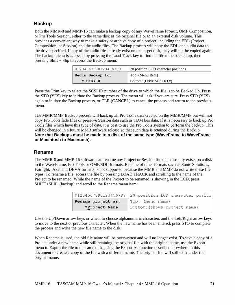
MMP-16 TASCAM MMP-16 Owner’s Manual • Chapter 4 • MMP-16 Operation 71
BackupBoth the MMR-8 and MMP-16 can make a backup copy of any WaveFrame Project, OMF Composition,or Pro Tools Session, either to the same disk as the original file or to an external disk volume. Thisprovides a convenient way to make a safety or archive copy of a project, including the EDL (Project,Composition, or Session) and the audio files. The Backup process will copy the EDL and audio data tothe drive specified. If any of the audio files already exist on the target disk, they will not be copied again.The backup menu is accessed by pressing the Load Track key to find the file to be backed up, thenpressing Shift + Slip to access the Backup menu:
01234567890123456789 20 position LCD character positions
Begin Backup to: Top: (Menu Item)
* Disk 0 Bottom: (Drive SCSI ID #)
Press the Trim key to select the SCSI ID number of the drive to which the file is to be Backed Up. Pressthe STO (YES) key to initiate the Backup process. The menu will ask if you are sure. Press STO (YES)again to initiate the Backup process, or CLR (CANCEL) to cancel the process and return to the previousmenu.
The MMR/MMP Backup process will back up all Pro Tools data created on the MMR/MMP but will notcopy Pro Tools fade files or preserve Session data such as TDM bus data. If it is necessary to back up ProTools files which have this type of data, it is best to use the Pro Tools system to perform the backup. Thiswill be changed in a future MMR software release so that such data is retained during the Backup.Note that Backups must be made to a disk of the same type (WaveFrame to WaveFrameor Macintosh to Macintosh).
RenameThe MMR-8 and MMP-16 software can rename any Project or Session file that currently exists on a diskin the WaveFrame, Pro Tools or OMF/SDII formats. Rename of other formats such as Sonic Solutions,Fairlight, Akai and DEVA formats is not supported because the MMR and MMP do not write these filetypes. To rename a file, access the file by pressing LOAD TRACK and scrolling to the name of theProject to be renamed. While the name of the Project to be renamed is showing in the LCD, pressSHIFT+SLIP (backup) and scroll to the Rename menu item:
01234567890123456789 20 position LCD character positions
Rename project as: Top: (menu name)
*Project Name Bottom:(shows project name)
Use the Up/Down arrow keys or wheel to choose alphanumeric characters and the Left/Right arrow keysto move to the next or previous character. When the new name has been entered, press STO to completethe process and write the new file name to the disk.
When Rename is used, the old file name will be overwritten and will no longer exist. To save a copy of aProject under a new name while still retaining the original file with the original name, use the Exportmenu to Export the file to the same disk, using the Export As function described elsewhere in thisdocument to create a copy of the file with a different name. The original file will still exist under theoriginal name.
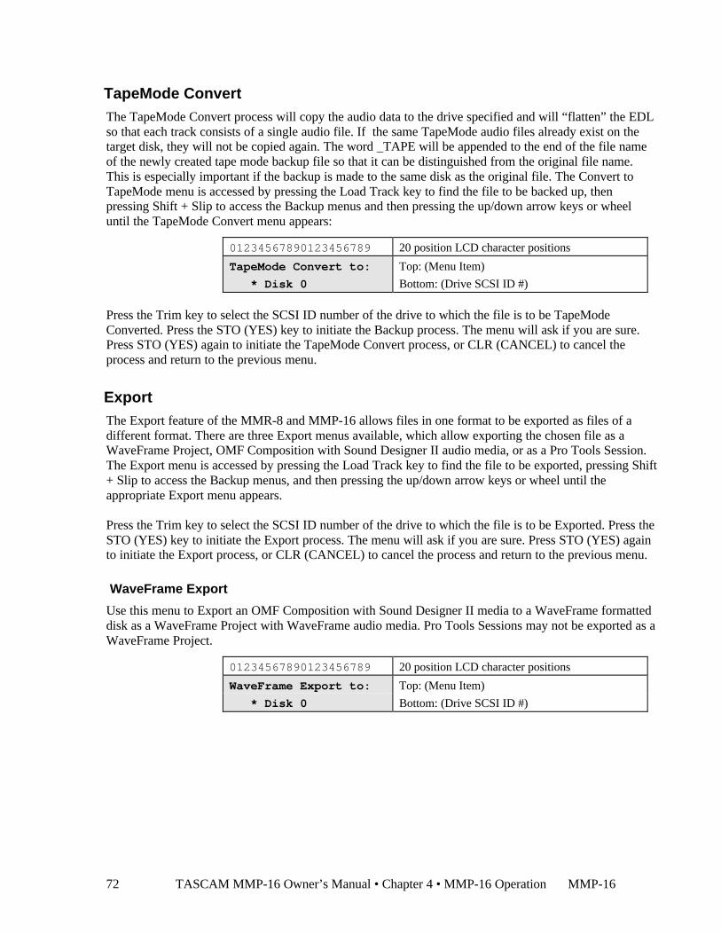
TASCAM MMP-16 Owner’s Manual • Chapter 4 • MMP-16 Operation MMP-1672
TapeMode ConvertThe TapeMode Convert process will copy the audio data to the drive specified and will “flatten” the EDLso that each track consists of a single audio file. If the same TapeMode audio files already exist on thetarget disk, they will not be copied again. The word _TAPE will be appended to the end of the file nameof the newly created tape mode backup file so that it can be distinguished from the original file name.This is especially important if the backup is made to the same disk as the original file. The Convert toTapeMode menu is accessed by pressing the Load Track key to find the file to be backed up, thenpressing Shift + Slip to access the Backup menus and then pressing the up/down arrow keys or wheeluntil the TapeMode Convert menu appears:
01234567890123456789 20 position LCD character positions
TapeMode Convert to: Top: (Menu Item)
* Disk 0 Bottom: (Drive SCSI ID #)
Press the Trim key to select the SCSI ID number of the drive to which the file is to be TapeModeConverted. Press the STO (YES) key to initiate the Backup process. The menu will ask if you are sure.Press STO (YES) again to initiate the TapeMode Convert process, or CLR (CANCEL) to cancel theprocess and return to the previous menu.
ExportThe Export feature of the MMR-8 and MMP-16 allows files in one format to be exported as files of adifferent format. There are three Export menus available, which allow exporting the chosen file as aWaveFrame Project, OMF Composition with Sound Designer II audio media, or as a Pro Tools Session.The Export menu is accessed by pressing the Load Track key to find the file to be exported, pressing Shift+ Slip to access the Backup menus, and then pressing the up/down arrow keys or wheel until theappropriate Export menu appears.
Press the Trim key to select the SCSI ID number of the drive to which the file is to be Exported. Press theSTO (YES) key to initiate the Export process. The menu will ask if you are sure. Press STO (YES) againto initiate the Export process, or CLR (CANCEL) to cancel the process and return to the previous menu.
WaveFrame Export
Use this menu to Export an OMF Composition with Sound Designer II media to a WaveFrame formatteddisk as a WaveFrame Project with WaveFrame audio media. Pro Tools Sessions may not be exported as aWaveFrame Project.
01234567890123456789 20 position LCD character positions
WaveFrame Export to: Top: (Menu Item)
* Disk 0 Bottom: (Drive SCSI ID #)

MMP-16 TASCAM MMP-16 Owner’s Manual • Chapter 4 • MMP-16 Operation 73
OMF Export
Use this menu to Export a WaveFrame Project (with WaveFrame audio media), or a Pro Tools Sessionfile (with Sound Designer II audio media) to a Macintosh formatted disk as an OMF Compositionreferencing Sound Designer II audio media files.
01234567890123456789 20 position LCD character positions
OMF Export to: Top: (Menu Item)
* Disk 0 Bottom: (Drive SCSI ID #)
To perform the OMF export operation, first select the project that you wish to convert by pressing LOADTRACK on the MMP front panel. Then use the Wheel to scroll through the names of available projectsand select the desired project.
To access OMF Export press SHIFT + SLIP (this accesses the BACKUP function) and use the Wheel toscroll through the Backup menus until “OMF Export to:” is displayed. Press TRIM and select the disk towhich you would like to export (shown by SCSI ID number) and then press STO. You will be promptedby the message “Are you sure (y/n)?” to confirm that you wish to perform an OMF export. Press YES toexecute the export or press NO to cancel the export. The target disk must be Macintosh-formatted inorder to perform the OMF export function. If it is not, the message “Vol does not support format” will bedisplayed. The newly created OMF project will have the same name as the project from which itoriginated, but it will be identifiable by the extension “.omf” which is automatically added to the filename of the exported file. The WaveFrame project, from which the OMF project was created, will remainunaffected.
To Import the OMF Export File into Pro ToolsThe OMF export files created by the MMP can be imported into the Pro Tools Session format by usingthe Digidesign OMF Tool software to convert the OMF Composition (EDL file) into the Pro ToolsSession EDL format. Sound file data is not re-written for this import step. To get the Digidesign OMFTool, contact your authorized Digidesign representative, or go to the following FTP site to download theDigidesign OMF Tool:
ftp://ftp.digidesign.com/pub/support/digi/mac/PTs/
Once at this site, download the file OMFTool203.sea.hqx onto a Macintosh computer and un-stuff thefile. Once you have completed installation of the software, use it to translate the OMF Composition filesgenerated by the MMP into Pro Tools Session files. Then open the Session files directly in Pro Tools.
Crossfades in OMFOccasionally a WaveFrame project will have an asymmetrical crossfade that must be adjusted in order toperform an OMF Export, since asymmetrical crossfades in OMF files are not supported. This is very rare,but when this situation does arise the message “OK to conform xfades?” will be displayed. AnsweringYES will conform the crossfades (make them symmetrical) and the OMF export will be performed. If NOis selected the message “EDL not exportable, try TapeMode convert first” will be displayed. Once theproject is converted to TapeMode it is possible to perform an OMF Export without conforming thecrossfades. This is because all crossfades are rendered into a single media file per track after using theTape Mode Convert backup function.
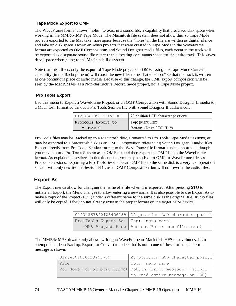
TASCAM MMP-16 Owner’s Manual • Chapter 4 • MMP-16 Operation MMP-1674
Tape Mode Export to OMF
The WaveFrame format allows “holes” to exist in a sound file, a capability that preserves disk space whenworking in the MMR/MMP Tape Mode. The Macintosh file system does not allow this, so Tape Modeprojects exported to the Mac take more space because the “holes” in the file are written as digital silenceand take up disk space. However, when projects that were created in Tape Mode in the WaveFrameformat are exported as OMF Compositions and Sound Designer media files, each event in the track willbe exported as a separate sound file rather than allocating continuous space for the entire track. This savesdrive space when going to the Macintosh file system.
Note that this affects only the export of Tape Mode projects to OMF. Using the Tape Mode Convertcapability (in the Backup menu) will cause the new files to be “flattened out” so that the track is writtenas one continuous piece of audio media. Because of this change, the OMF export composition will beseen by the MMR/MMP as a Non-destructive Record mode project, not a Tape Mode project.
Pro Tools Export
Use this menu to Export a WaveFrame Project, or an OMF Composition with Sound Designer II media toa Macintosh-formatted disk as a Pro Tools Session file with Sound Designer II audio media.
01234567890123456789 20 position LCD character positions
ProTools Export to: Top: (Menu Item)
* Disk 0 Bottom: (Drive SCSI ID #)
Pro Tools files may be Backed up to a Macintosh disk, Converted to Pro Tools Tape Mode Sessions, ormay be exported to a Macintosh disk as an OMF Composition referencing Sound Designer II audio files.Export directly from Pro Tools Session format to the WaveFrame file format is not supported, althoughyou may export a Pro Tools Session as an OMF file and then export the OMF file to the WaveFrameformat. As explained elsewhere in this document, you may also Export OMF or WaveFrame files asProTools Sessions. Exporting a Pro Tools Session as an OMF file to the same disk is a very fast operationsince it will only rewrite the Session EDL as an OMF Composition, but will not rewrite the audio files.
Export AsThe Export menus allow for changing the name of a file when it is exported. After pressing STO toinitiate an Export, the Menu changes to allow entering a new name. It is also possible to use Export As tomake a copy of the Project (EDL) under a different name to the same disk as the original file. Audio fileswill only be copied if they do not already exist in the proper format on the target SCSI device.
01234567890123456789 20 position LCD character positions
Pro Tools Export As: Top: (menu name)
*MMR Project Name Bottom:(Enter new file name)
The MMR/MMP software only allows writing to WaveFrame or Macintosh HFS disk volumes. If anattempt is made to Backup, Export, or Convert to a disk that is not in one of these formats, an errormessage is shown:
01234567890123456789 20 position LCD character positions
File Top: (menu name)
Vol does not support format Bottom:(Error message – scroll
to read entire message on LCD)
MMP-16 TASCAM MMP-16 Owner’s Manual • Chapter 4 • MMP-16 Operation 75
Dynamic Backup Status DisplayClear the display and press SHIFT + SLIP (Backup) to interrogate the current status of the backupprocess. The current status (percent complete) for the Backup, Tape Mode Convert, and OMF Exportfunctions in the Backup Menu is dynamically updated and will display progress all the way to completionas it goes.
Using RegistersThere are 21 time code registers (10 memory registers and 11 special-purpose registers) that hold timecode values for immediate or future use. Some of the special-purpose registers are automatically filledwhen tracks are loaded (e.g., HEAD, TAIL), others are updated according to the current play or stop timecode reading (e.g., PREV, NEXT), while others (notably memory registers 0 - 9) are entered eithermanually or through using CAPT, STO, or RCL functions. The register currently displayed on the lowerline of the LCD is called the active register. By default, the active register is the entry register, which isthe register used to capture manual time code input from the keypad.
Accessing registers is done using a two-keystroke command sequence which consists of the function(store, recall, capture) and the numeric or shifted numeric key associated with the desired register (i.e., 0 -9). Before pressing the second key, operations can be canceled by pressing the same function key again orby pressing CLR, but are typically ended by completing the full key sequence.
Recalling Registers
To recall the time code previously stored into a memory register, press RCL (the RCL LED will flash)and then press the desired key (0 - 9). The RCL LED will turn off and the time code from that registerwill be displayed in the bottom line of the display, with a prefixed heading indicating which register is thecurrently displayed (active) register. All special-purpose registers may be recalled similarly, first bypressing RCL, then SHIFT+the desired numeric key. Special-purpose registers have their names writtenon the front panel directly above the numeric key with which they are associated. Note that if RCL is notpressed first, then pressing SHIFT+ one of these special-purpose register keys — LYNX SYNC, IN,OUT, HEAD, TAIL, NEXT EDIT, or PREV EDIT — will cause the transport to automatically locate tothe register contents. This is a short cut for RCL + SHIFT+ register key + LOC.
Capturing the Current Time Code
During any transport state (stop, play), the current time code shown on the top line of the LCD displaycan be captured into the entry register by pressing the CAPT key. The captured time code can be stored toone of the ten memory registers for later recall, or to one of the five “writeable” special-purpose registers(IN, OUT, OFST, LYNX SYNC, TIME). The capture key places the time code value from the top line ofthe display into the active time code register in the bottom line of the display. After capturing the timecode value the CAPT LED will flash until a target register key is pressed to place the captured time codevalue into that register. Note that pressing CAPT automatically readies the system to store the value intothe target register, as if the STO key had already been pressed. To complete the capture operation, eitherpress a target register key or press CLR to cancel.
TASCAM MMP-16 Owner’s Manual • Chapter 4 • MMP-16 Operation MMP-1676
Trimming Time Code Values
Any time a writeable register is shown in the bottom line of the display (usually by being recalled), it canbe trimmed as required. There are two types of trimming: static and dynamic. Dynamic trim is desirableonly in certain special situations, and differs from static trim in that the register values are sent to thetransport immediately as they are changed. In static trim, register values are sent to the transport at thepoint where trim mode is exited. Note that Trim mode cancels Jog or Shuttle modes, if active, since Trim,Jog, and Shuttle are mutually exclusive.
To trim the time code in the active register, press TRIM (for static trim) or SHIFT+TRIM (for dynamictrim). The TRIM LED will flash slowly (static trim) or flash quickly (dynamic trim) to indicate trim modeis active. Rotate the Wheel clockwise or press the up-arrow key to increment the time code numbers, orrotate the wheel counterclockwise or press the down-arrow key to decrement the time code numbers.
When the desired value is reached, press TRIM again to exit trim mode. This saves the value as trimmed,while continuing to display the register last trimmed. If you don’t want to save the trimmed value, exittrim mode by pressing CLR. This cancels Trim mode and restores the register to its pre-trimmed value.
Using the Entry RegisterIn the Normal state, the bottom line of the LCD typically displays the entry register. This register is usedfor manual time code entry from the keypad. It can be used to update memory registers and the writeablespecial-purpose registers. Once time code is displayed in the entry register, the MMP-16 can beimmediately located to that time by pressing the LOC key. The following methods may be used to entertime code into the entry register while in the Normal state):
Direct time codeentry
Use the numeric keys to type in the time code. The keyed time code will replaceany existing time code in the display. Use this method if the time code position isknown. Pressing CLR will reset any existing time code in the register to zero,making it easier to enter new time code numbers.
Capture thetime code
Press CAPT during play or while stopped. This copies the “play head”time code shown in the top line, at the moment the CAPT key is pressed, to theentry register on the bottom line.
Recall, Trim,and Storea Register
Recall and trim one of the ten memory registers (using RCL+0 - 9), or one of thespecial-purpose registers (using RCL+SHIFT+0 - 9), and press the STO key. Theregister time code value is then copied to the entry register.
The time code value in the entry register can be trimmed, as required, by using the Wheel or Up/Downarrow keys to increment or decrement the time code before any other action is taken on the time code.
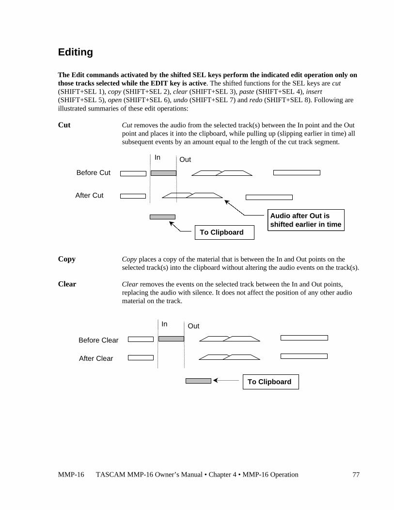
MMP-16 TASCAM MMP-16 Owner’s Manual • Chapter 4 • MMP-16 Operation 77
Editing
The Edit commands activated by the shifted SEL keys perform the indicated edit operation only onthose tracks selected while the EDIT key is active. The shifted functions for the SEL keys are cut(SHIFT+SEL 1), copy (SHIFT+SEL 2), clear (SHIFT+SEL 3), paste (SHIFT+SEL 4), insert(SHIFT+SEL 5), open (SHIFT+SEL 6), undo (SHIFT+SEL 7) and redo (SHIFT+SEL 8). Following areillustrated summaries of these edit operations:
Cut Cut removes the audio from the selected track(s) between the In point and the Outpoint and places it into the clipboard, while pulling up (slipping earlier in time) allsubsequent events by an amount equal to the length of the cut track segment.
Copy Copy places a copy of the material that is between the In and Out points on theselected track(s) into the clipboard without altering the audio events on the track(s).
Clear Clear removes the events on the selected track between the In and Out points,replacing the audio with silence. It does not affect the position of any other audiomaterial on the track.
In Out
To Clipboard
Audio after Out isshifted earlier in time
In Out
To Clipboard
Before Cut
After Cut
Before Clear
After Clear
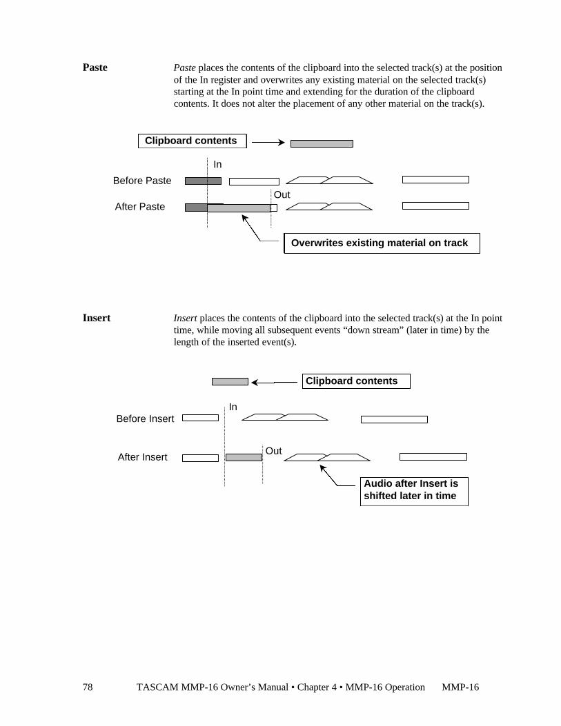
TASCAM MMP-16 Owner’s Manual • Chapter 4 • MMP-16 Operation MMP-1678
Paste Paste places the contents of the clipboard into the selected track(s) at the positionof the In register and overwrites any existing material on the selected track(s)starting at the In point time and extending for the duration of the clipboardcontents. It does not alter the placement of any other material on the track(s).
Insert Insert places the contents of the clipboard into the selected track(s) at the In pointtime, while moving all subsequent events “down stream” (later in time) by thelength of the inserted event(s).
In
Before Paste
After Paste
Overwrites existing material on track
In
Clipboard contents
Audio after Insert isshifted later in time
Before Insert
After Insert
Clipboard contents
Out
Out
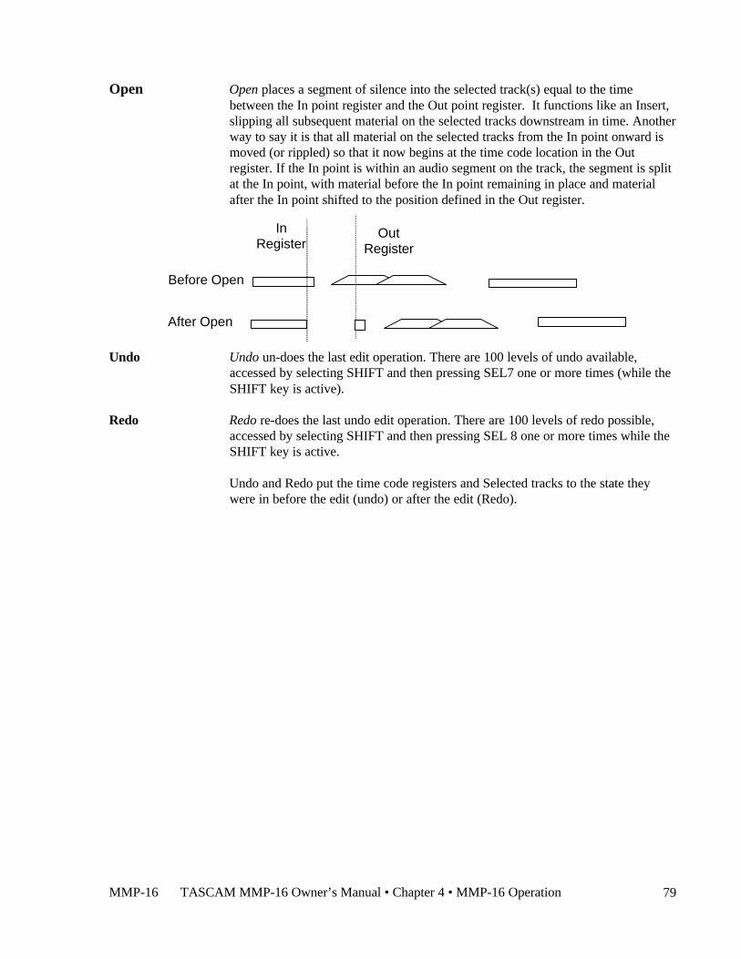
MMP-16 TASCAM MMP-16 Owner’s Manual • Chapter 4 • MMP-16 Operation 79
Open Open places a segment of silence into the selected track(s) equal to the timebetween the In point register and the Out point register. It functions like an Insert,slipping all subsequent material on the selected tracks downstream in time. Anotherway to say it is that all material on the selected tracks from the In point onward ismoved (or rippled) so that it now begins at the time code location in the Outregister. If the In point is within an audio segment on the track, the segment is splitat the In point, with material before the In point remaining in place and materialafter the In point shifted to the position defined in the Out register.
Undo Undo un-does the last edit operation. There are 100 levels of undo available,accessed by selecting SHIFT and then pressing SEL7 one or more times (while theSHIFT key is active).
Redo Redo re-does the last undo edit operation. There are 100 levels of redo possible,accessed by selecting SHIFT and then pressing SEL 8 one or more times while theSHIFT key is active.
Undo and Redo put the time code registers and Selected tracks to the state theywere in before the edit (undo) or after the edit (Redo).
InRegister
OutRegister
After Open
Before Open
TASCAM MMP-16 Owner’s Manual • Chapter 4 • MMP-16 Operation MMP-1680
EDIT Pressing this key (while in the Normal state) allows the SEL keys to select whichtrack(s) will be later edited (using the SHIFT+SEL edit functions described above).The suggested sequence of keystrokes to follow for editing is:
Press the EDIT key to enter the Edit Track Mode, then the SEL key for the track(s)to be edited.
Set the In and Out points to define the range of material to be affected on theselected track(s).
Press SHIFT + SEL for the desired edit function (Cut, Clear, Copy).
Set the In point to the time code location where the material on the clipboard is tobe placed.
While the EDIT key is still enabled (amber LED is on), press the SEL key for thetrack(s) where the material on the clipboard is to be placed.
Press SHIFT + SEL for the desired edit function (Paste, Insert)
This completes the Edit operation. Note that Open operates differently in that itdoes not place material from the Clipboard into a track, but instead references thelength of time between the In and Out registers and moves the downstreammaterial by that amount.
If material from a single track is placed on the clipboard, but multiple destinationtracks are selected, only the first selected track (counting upwards from 1 to 8) willbe used as the target for the Paste or Insert.
If multiple tracks are placed on the clipboard, then multiple destination tracks canbe selected. Selecting the same number of target tracks as used for the clipboardoperation insures the material will be placed on only those tracks. If a differentnumber of target tracks are selected, the Paste or Insert will place the clipboardmaterial consecutively on the selected tracks, starting with the first selected track,up to the limit of the number of tracks selected. For example:
If material is Copied from Track 1, then tracks 3, 4, 6, and 8 are Selected for thetarget, the Paste operation will only put material on track 3.
If material is Copied from tracks 2, 4, and 6, then tracks 1 through 8 are allselected, the Paste operation will place material on tracks 1, 2, and 3. If only threetracks are selected for the Paste (for example, tracks 3, 5, and 7) then the materialwill go on those tracks in order.
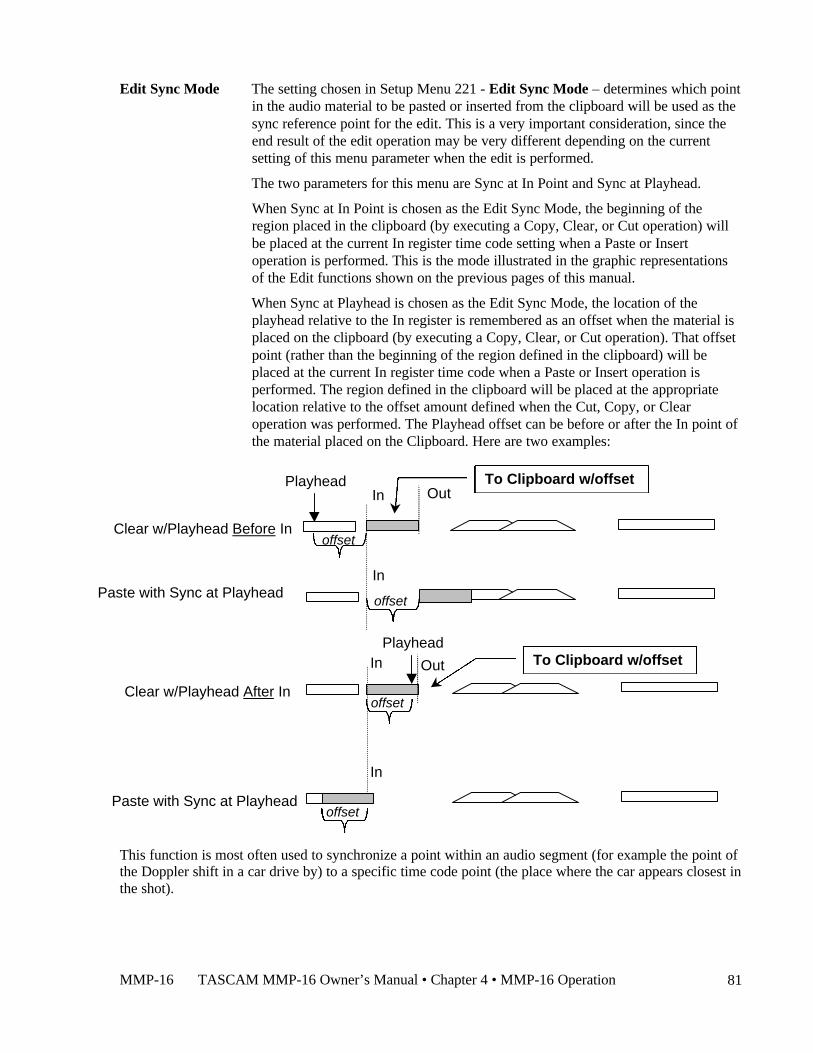
MMP-16 TASCAM MMP-16 Owner’s Manual • Chapter 4 • MMP-16 Operation 81
Edit Sync Mode The setting chosen in Setup Menu 221 - Edit Sync Mode – determines which pointin the audio material to be pasted or inserted from the clipboard will be used as thesync reference point for the edit. This is a very important consideration, since theend result of the edit operation may be very different depending on the currentsetting of this menu parameter when the edit is performed.
The two parameters for this menu are Sync at In Point and Sync at Playhead.
When Sync at In Point is chosen as the Edit Sync Mode, the beginning of theregion placed in the clipboard (by executing a Copy, Clear, or Cut operation) willbe placed at the current In register time code setting when a Paste or Insertoperation is performed. This is the mode illustrated in the graphic representationsof the Edit functions shown on the previous pages of this manual.
When Sync at Playhead is chosen as the Edit Sync Mode, the location of theplayhead relative to the In register is remembered as an offset when the material isplaced on the clipboard (by executing a Copy, Clear, or Cut operation). That offsetpoint (rather than the beginning of the region defined in the clipboard) will beplaced at the current In register time code when a Paste or Insert operation isperformed. The region defined in the clipboard will be placed at the appropriatelocation relative to the offset amount defined when the Cut, Copy, or Clearoperation was performed. The Playhead offset can be before or after the In point ofthe material placed on the Clipboard. Here are two examples:
This function is most often used to synchronize a point within an audio segment (for example the point ofthe Doppler shift in a car drive by) to a specific time code point (the place where the car appears closest inthe shot).
In OutTo Clipboard w/offset
Clear w/Playhead Before In
Playhead
offset
Paste with Sync at PlayheadIn
offset
In Out To Clipboard w/offset
Clear w/Playhead After In
Playhead
offset
In
Paste with Sync at Playheadoffset
TASCAM MMP-16 Owner’s Manual • Chapter 4 • MMP-16 Operation MMP-1682
Local & Studio MonitoringA front panel headphone jack allows the MMP-16 operator to locally monitor one or more tracks, right atthe front panel, without affecting the output signals. The rear panel mini-jack output on the PRX card isdesigned for studio monitoring using a customer-supplied studio monitor amplifier and speaker. Themini-jack level is not controlled by the front panel volume control, and the audio output of the mini-jackalways presents a mono sum mix of all tracks according to the track monitor selection chosen on the frontpanel. Headphone and studio monitoring both follow the Input Monitor selection, so if a track is beingmonitored and it is switched to Input Monitor, the audio change will be heard in the headphones andstudio.
Headphone Volume (LEVEL)
The headphone monitoring volume is set by the LEVEL control next to the headphone jack.
Headphone Jack (PHONES)
Even though the Headphone jack is a standard pro-size stereo headphone jack (phone-type), all trackmonitoring is done in mono. Either low (8 ohms) or high impedance (600 ohms) headphones can be used.
HEADPHONE NOTE:
To prevent hearing damage, always turn the Headphone Level full off before putting onthe headphones and leave the Level at a low volume until at least one track has beenselected for monitoring.
The Lynx BusThe Lynx bus allows control of the MMP via a TimeLine Lynx Keyboard Control Unit (KCU). Connectthe KCU to one of the Lynx bus connectors on the back of the MMP. It is not necessary to have a Lynx 2module as part of the system, since the MMP behaves as a Lynx synchronizer itself when connected to aKCU. Other Lynx modules may then be connected through the other Lynx bus connector and the entiresystem (up to a limit of six devices) controlled from the KCU.
To setup the MMP to be controlled from a Lynx KCU, set menu 120 (Lynx Bus) to Slave/KCU and usemenu 121 (Lynx Address) to set a valid Lynx address (one not used by any other Lynx device controlledform the KCU). Although normal transport and track arm functions may be controlled from a standardKCU, there is a special version of the Lynx KCU software (version 900) which provides increasedsupport for special MMP functions.
The KCU 900 software provides the following features for controlling the MMP-16 and MMR-8:
• Transport Control• Track Record Arm/Select (MMR-8 only)• Slip Track/Region• Undo/Redo• Goto Prev/Next Edit• Goto Head/Tail• Clear/PasteNote that No support is provided by the KCU 900 software for the Lynx System Supervisor Unit (SSU)
MMP-16 TASCAM MMP-16 Owner’s Manual • Chapter 4 • MMP-16 Operation 83
Transport ControlThe Lynx KCU will recognize the MMP-16 unit and will control all of the normal transport functions ofthe unit. Note that the KCU does not support reverse play of multiple MMP units. When using the RollBack key for reverse play, it is first necessary to solo a machine.
Track Record Arm/Select (MMR-8 Only)To arm a track for record or to select a track for an edit or goto operation, press the Track key on the KCUand then press the appropriate number key on the calculator keypad to select or arm the desired track. TheSlip operation, as well as goto Prev/Next edit, goto Head/Tail, and Clear/Paste will operate only on tracksthat have been selected in this manner. If one of these operations is attempted, but a track is not selected,the KCU display will prompt you to select a track first.
Head/TailHold CLR while pressing the Head or Tail key to set the current time to the beginning or end of thematerial on the selected track(s). You may then play from that point, or store the value in the desiredtimecode register (press STO then the appropriate key on the Calculator).
Slip Track/RegionThe K900 KCU software has a Slip key in the place of the key previously labeled END PT in the SpecialFunctions section of the KCU. Pressing this key puts the KCU in a “Trim” mode to allow slipping theselected material forward or backward in time. The selection is defined as all material located between theIn and Out timecode registers on tracks that have been armed/selected as described above (see TrackRecord Arm/Select). Upon pressing Slip, the – and + keys will highlight and the Wheel will be in Trimmode. Use the Wheel or keys to enter a trim value to indicate how far the selected region will be slipped.To end the operation and complete the Slip, press either the Trim key or the Slip key. Note that slippingmaterial within a track will automatically overwrite any previous material on the selected track(s) at thenew location.
To slip an entire track, use the goto Head/Tail commands (Hold CLR while pressing the Head or Tailkey) to set the current time and then store the value in the appropriate register (press STO then the In orOut key on the Calculator) before executing the Slip command. To slip a single edit in an EDL, use thePREV and NEXT keys in a similar fashion to locate the beginning and end of the Edit on the desired trackand store the time value for the beginning and end of the edit region in the In and Out registers beforeexecuting the Slip command.
Prev/NextHold CLR while pressing the PREV and NEXT keys to set the current time to the beginning or end of anedited region on the desired track. You may then play from that point, or store the value in the desiredtimecode register (press STO then the appropriate key on the Calculator).
Undo/RedoHold CLR while pressing the Undo or Redo key to undo or redo the previous edit operation. The MMP-16 supports ten levels of Undo and Redo. The MMP display will indicate which level of Undo or Redo isaffected by the operation, up to the maximum or ten.

TASCAM MMP-16 Owner’s Manual • Chapter 4 • MMP-16 Operation MMP-1684
Clear/PasteHold CLR while pressing the Clear or Paste keys to perform these edit operations on the selectedmaterial. Clear will remove audio from the selected tracks between the In and Out times, replacing it withsilence and will place the material into the MMP clipboard memory. Paste will place the material from theClipboard memory at the time set in the In timecode register on the selected track.
MMP-16 TASCAM MMP-16 Owner’s Manual • Chapter 4 • MMP-16 Operation 85
The MMR BusThe operation of multiple MMP-16s may be synchronized by using the supplied 15-pin sync cable toconnect the MMP units together via the MMR bus sync connection (the two 15-pin connectors on theSYNC card). Since this bus is self-terminating, simply daisy chain all the MMP-16s together in any order.The MMR bus supports four independent Sync Groups, so any machine on the MMR bus can be assignedto any of the four groups at any time without changing the physical connections. Also, since the MMRbus carries system-wide frame and sample references, no other connections are required between thevarious MMP-16s to provide sample accurate synchronization lock between them.
Each MMR/MMP Sync Group on the MMR bus must have a Master MMR or MMP unit, with the rest ofthe units in the Sync Group acting as Slaves to the Master unit. It is only necessary for the Master unit toreceive incoming synchronization signals from external sources (digital clock, video sync, SMPTE/EBU,biphase, etc.) since the remaining units on the associated MMR bus Sync Group will slave only to theMaster unit. This allows up 100 units to work synchronously and sample accurately together as one largemachine without having to feed duplicate sync reference signals independently to each unit.
Once the units to be linked using the MMR bus have been physically connected via the MMR busconnection, their transports can be operated together as one large system. There are several Setup menuswhich are used to govern how each unit behaves within the system. These are described here.
Menu 110 (MMR Bus Request) allows each MMR/MMP to request to be Master, Slave, or off the MMRbus altogether. Only one MMR/MMP per sync group can act as master. If multiple units are set to requestmaster status through this menu, the MMR Bus system will automatically choose the unit with the lowestserial number among those making the request to be set as the master for the sync group. The appropriateMAST or SLAVE LED will light on the front panel to show the unit’s status on the MMR bus.
Menu 111 (Ident Request) allows each unit to request an individual identity on the MMR bus. If no otherunit is requesting the same ID, the system will set the unit ID to the requested number and that numberwill be displayed in the Ident window on the front panel of the MMP. If another unit has requested thesame ID, the system will resolve the conflict and automatically assign each unit a unique ID on the bus. Ifan ID other than that requested is assigned due to a conflict, this field will not change, and the machinewill continue to request this ID whenever it is powered up or added to an MMR bus chain.
Menu 112 (Ident Assigned) is an information display only (data cannot be entered) that shows thecurrently assigned identity for this unit on the MMR bus. This number may be different than the IDrequested if there is a conflict on the MMR bus and the system has assigned the unit a different ID.
To synchronize a slave unit to the master unit on the bus once the above settings are confirmed, place theslave unit online (press the ONLINE key on the transport).
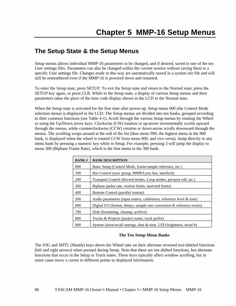
TASCAM MMP-16 Owner’s Manual • Chapter 5 • MMP-16 Setup Menus MMP-1686
Chapter 5 MMP-16 Setup Menus
The Setup State & the Setup Menus
Setup menus allows individual MMP-16 parameters to be changed, and if desired, saved to one of the tenUser settings files. Parameters can also be changed within the current session without saving them to aspecific User settings file. Changes made in this way are automatically stored in a system init file and willstill be remembered even if the MMP-16 is powered down and restarted.
To enter the Setup state, press SETUP. To exit the Setup state and return to the Normal state, press theSETUP key again, or press CLR. While in the Setup state, a display of various Setup menus and theirparameters takes the place of the time code display shown in the LCD in the Normal state.
When the Setup state is activated for the first time after power-up, Setup menu 000 (the Control Modeselection menu) is displayed in the LCD. The Setup menus are divided into ten banks, grouped accordingto their common functions (see Table 4-1). Scroll through the various Setup menus by rotating the Wheelor using the Up/Down arrow keys. Clockwise (CW) rotation or up-arrow incrementally scrolls upwardthrough the menus, while counterclockwise (CCW) rotation or down-arrow scrolls downward through themenus. The scrolling wraps around at the end of the list (thus menu 990, the highest menu in the 900bank, is displayed when the wheel is rotated CCW from menu 000, and vice versa). Jump directly to anymenu bank by pressing a numeric key while in Setup. For example, pressing 3 will jump the display tomenu 300 (Biphase Frame Rate), which is the first menu in the 300 bank.
BANK # BANK DESCRIPTION
000 Basic Setup (Control Mode, frame/sample reference, etc.)
100 Bus Control (sync group, MMR/Lynx bus, interlock)
200 Transport Control (Record modes, Loop modes, pre/post roll, etc.)
300 Biphase (pulse rate, motion limits, start/end limits)
400 Remote Control (parallel remote)
500 Audio parameters (input source, calibration, reference level & tone)
600 Digital I/O (format, delays, sample rate conversion & reference tracks)
700 Disk (formatting, cleanup, archive)
800 Tracks & Projects (project name, track prefix)
900 System (store/recall settings, date & time, LED brightness, serial #)
The Ten Setup Menu Banks
The JOG and SHTL (Shuttle) keys above the Wheel take on their alternate reversed text-labeled functions(left and right arrows) when pressed during Setup. Note that these are not shifted functions, but alternatefunctions that occur in the Setup or Track states. These keys typically affect window scrolling, but insome cases move a cursor to different points in displayed information.
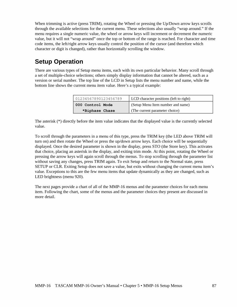
MMP-16 TASCAM MMP-16 Owner’s Manual • Chapter 5 • MMP-16 Setup Menus 87
When trimming is active (press TRIM), rotating the Wheel or pressing the Up/Down arrow keys scrollsthrough the available selections for the current menu. These selections also usually “wrap around.” If themenu requires a single numeric value, the wheel or arrow keys will increment or decrement the numericvalue, but it will not “wrap around” once the top or bottom of the range is reached. For character and timecode items, the left/right arrow keys usually control the position of the cursor (and therefore whichcharacter or digit is changed), rather than horizontally scrolling the window.
Setup OperationThere are various types of Setup menu items, each with its own particular behavior. Many scroll througha set of multiple-choice selections; others simply display information that cannot be altered, such as aversion or serial number. The top line of the LCD in Setup lists the menu number and name, while thebottom line shows the current menu item value. Here’s a typical example:
01234567890123456789 LCD character positions (left to right)
000 Control Mode (Setup Menu Item number and name)
*Biphase Chase (The current parameter choice)
The asterisk (*) directly before the item value indicates that the displayed value is the currently selectedvalue.
To scroll through the parameters in a menu of this type, press the TRIM key (the LED above TRIM willturn on) and then rotate the Wheel or press the up/down arrow keys. Each choice will be sequentiallydisplayed. Once the desired parameter is shown in the display, press STO (the Store key). This activatesthat choice, placing an asterisk in the display, and exiting trim mode. At this point, rotating the Wheel orpressing the arrow keys will again scroll through the menus. To stop scrolling through the parameter listwithout saving any changes, press TRIM again. To exit Setup and return to the Normal state, pressSETUP or CLR. Exiting Setup does not save a value, but exits without changing the current menu item’svalue. Exceptions to this are the few menu items that update dynamically as they are changed, such asLED brightness (menu 920).
The next pages provide a chart of all of the MMP-16 menus and the parameter choices for each menuitem. Following the chart, some of the menus and the parameter choices they present are discussed inmore detail.
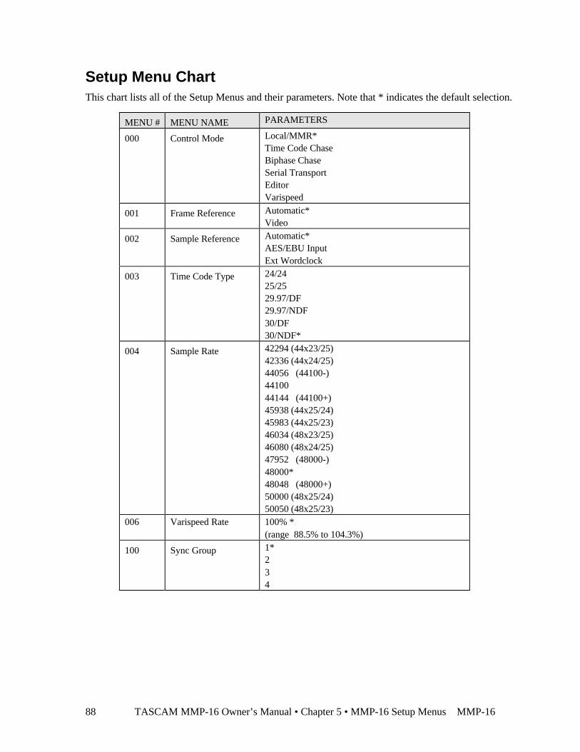
TASCAM MMP-16 Owner’s Manual • Chapter 5 • MMP-16 Setup Menus MMP-1688
Setup Menu ChartThis chart lists all of the Setup Menus and their parameters. Note that * indicates the default selection.
MENU # MENU NAME PARAMETERS
000 Control Mode Local/MMR*Time Code ChaseBiphase ChaseSerial TransportEditorVarispeed
001 Frame Reference Automatic*Video
002 Sample Reference Automatic*AES/EBU InputExt Wordclock
003 Time Code Type 24/2425/2529.97/DF29.97/NDF30/DF30/NDF*
004 Sample Rate 42294 (44x23/25)42336 (44x24/25)44056 (44100-)4410044144 (44100+)45938 (44x25/24)45983 (44x25/23)46034 (48x23/25)46080 (48x24/25)47952 (48000-)48000*48048 (48000+)50000 (48x25/24)50050 (48x25/23)
006 Varispeed Rate 100% *(range 88.5% to 104.3%)
100 Sync Group 1*234

MMP-16 TASCAM MMP-16 Owner’s Manual • Chapter 5 • MMP-16 Setup Menus 89
MENU # MENU NAME PARAMETERS
110 MMR Bus Request MasterOff*Slave
111 Ident Request Auto Assign*01(Range 01-100)
112 Ident Assigned 01*(Range 01–100 read-only display)
120 Lynx Bus Off*Slave/KCUMaster
121 Lynx Address 1*Range: 0 through 127
122 Lynx V500 Mode Off*On
210 Loop Mode Play Repeatedly*Play once and CuePlay once and Stop
211 Loop Record Repeat Record*Record Once OnlyRepeat w/Unload
212 Pre-Roll 00:00:05:00*
213 Post-roll 00:00:02:00*
220 Next/Prev Mode Event*Cue
221 Edit Sync Mode Sync at In Point*Sync at Playhead
250 Slip Commit All Tracks*Track 1[lists all tracks through Track 8 on MMR, 16 onMMP]Track N
300 Biph Frame Rate 24 fps*25 fps30 fps
301 Biph Pulse Rate 2 ppf4 ppf10 ppf*20 ppf25 ppf50 ppf100 ppf
302 Biphase Input Biphase*Tach + DirTach + Inverse Dir
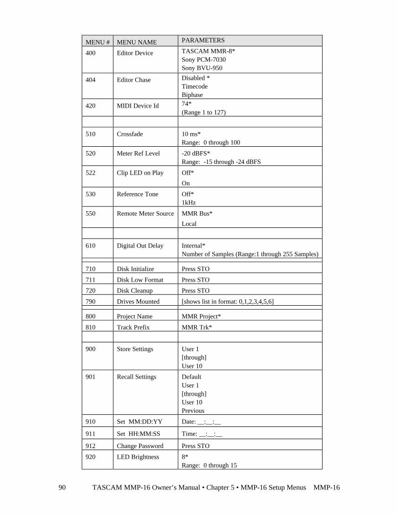
TASCAM MMP-16 Owner’s Manual • Chapter 5 • MMP-16 Setup Menus MMP-1690
MENU # MENU NAME PARAMETERS
400 Editor Device TASCAM MMR-8*Sony PCM-7030Sony BVU-950
404 Editor Chase Disabled *TimecodeBiphase
420 MIDI Device Id 74*(Range 1 to 127)
510 Crossfade 10 ms*Range: 0 through 100
520 Meter Ref Level -20 dBFS*Range: -15 through -24 dBFS
522 Clip LED on Play Off*
On
530 Reference Tone Off*1kHz
550 Remote Meter Source MMR Bus*
Local
610 Digital Out Delay Internal*Number of Samples (Range:1 through 255 Samples)
710 Disk Initialize Press STO
711 Disk Low Format Press STO
720 Disk Cleanup Press STO
790 Drives Mounted [shows list in format: 0,1,2,3,4,5,6]
800 Project Name MMR Project*
810 Track Prefix MMR Trk*
900 Store Settings User 1[through]User 10
901 Recall Settings DefaultUser 1[through]User 10Previous
910 Set MM:DD:YY Date: __:__:__
911 Set HH:MM:SS Time: __:__:__
912 Change Password Press STO
920 LED Brightness 8*Range: 0 through 15
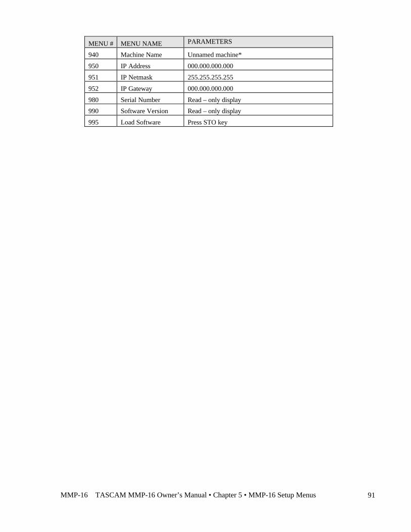
MMP-16 TASCAM MMP-16 Owner’s Manual • Chapter 5 • MMP-16 Setup Menus 91
MENU # MENU NAME PARAMETERS
940 Machine Name Unnamed machine*
950 IP Address 000.000.000.000
951 IP Netmask 255.255.255.255
952 IP Gateway 000.000.000.000
980 Serial Number Read – only display
990 Software Version Read – only display
995 Load Software Press STO key

TASCAM MMP-16 Owner’s Manual • Chapter 5 • MMP-16 Setup Menus MMP-1692
000 Basic Setup
This menu bank has settings for the most fundamental settings governing how the MM series machineresponds to external clocks and control. The items in this bank are:
• Control Mode• Frame Reference• Sample Reference• Timecode Type• Sample Rate• Varispeed Rate
000 Control Mode
The MMP-16 will always operate in one of six Control modes. The default Control mode, which is howthe MMP-16 starts up when the unit is first installed, is called the Local/Bus Control Mode.
To change the Control mode, select Setup menu 000 (press SETUP to display the Setup menus).Whenever the MMP-16 is powered up, the first menu displayed will always be menu 000 (“ControlMode”). Afterwards, the menu displayed when entering Setup mode is the last menu displayed. OnceSetup menu 000 (“Control Mode”) is displayed, press TRIM to change the Wheel and the Up/Downarrow keys to scroll through the seven menu choices under Setup menu 000. Once the desired operatingmode is displayed, press STO (the Store key) to select that choice. This immediately switches the variousparameters to the new control mode, typically causing several LEDs to change status according to thenew parameters. To exit Setup mode, press SETUP or the CLR (Clear) key.
Following is a more detailed description of the six control modes that are supported by the MMP-16:
Local/Bus
In local mode (offline) the MMP-16 functions like other stand-alone digital playback devices. No externalsync signals are required. The front panel transport keys offer direct control over system audio playback.When placed into bus (online) mode, the MMP-16 can function as either a master or a slave to otherMMR bus or Lynx bus devices, as set through Setup menu 110 (MMR Bus) and menu 120 (LYNX bus).
Time Code Chase
In Time Code Chase, the MMP-16 will slave to the time code coming from the time code input on therear panel when it is placed Online. In this mode the time code input must have valid time code in orderfor the MMP-16 to chase, lock, and synchronize itself to the incoming time code. Pressing any of thetransport keys will take the MMP-16 off-line and allow local control at any time. Placing the MMP-16back online will cause it to lock to and chase the selected time code once again.
Biphase Chase
In Biphase Chase, the MMP-16 chases, interlocks, and synchronizes to a biphase or tach/dir. signal onone of the four Biphase Inputs (the active input is determined by the Sync Group number set in menu100). The system locks and plays audio at speeds from 0 to 1.5 times play speed in both forward andreverse directions. The MMP-16 can then serve as a master for other devices on the MMR or Lynx buses.
MMP-16 TASCAM MMP-16 Owner’s Manual • Chapter 5 • MMP-16 Setup Menus 93
Serial Transport
This mode allows the MMP-16 to control an external audio or video transport connected to the 9-pinserial Transport connector. Video and audio decks using the P2 protocol can be controlled (includingmodels from Accom, Alesis, Ampex, Fostex, JVC, Otari, Panasonic, Sony, and TASCAM). When inSerial Tran mode, the MM series unit will output transport commands to external serial devices throughthe 9-pin serial Transport output using Sony P-2 protocol. The unit will then lock to the external serialdevice via linear timecode coming from the device through the MM unit’s timecode input (not throughserial timecode).
Editor
Using the Editor connector (and Sony P2 protocol) a video editor or other non-Lynx synchronizer cancontrol the MMP-16 transport functions when the MMP-16 Control Mode is set to Editor. When in Editormode, the MM series unit will respond to transport and track arming commands coming in to the 9-pinserial Editor port. This setting is typically used with traditional video edit controllers.
Varispeed
Varispeed mode allows for setting playback speed within a range of 87.5% to 112.5% of nominal playspeed. This range varies according to the sample rate selected. Varispeed varies the playback frequency aswell as the digital sample clock on the digital output.
Serial Editor Port DetailsThere are a number of important details to note about the Serial Editor port as noted below.
Record Ready Tallies
Record ready tallies issued over the 9-pin serial Editor port now include tracks armed at the MMR-8 frontpanel or MM-RC, and not just those tracks armed by serial command. This allows an external Serialdevice to know when a track has been armed for recording, regardless of the source of the track armcommand.
Sony P2 Chase and Offset Commands
Sony P-2 protocol Chase and Offset commands are accepted by the MMR/MMP. Setup Menu 404 allowsfor setting the chase source to either Timecode, Biphase, or Disabled.
Serial Editor Port Active When Not ONLINE
The MMR/MMP unit will follow transport, track arm, and record commands given on the 9-pin serialEditor port even when the unit is not ONLINE.
Automatic ONLINE
The MMR/MMP unit will automatically be placed in the ONLINE state when placed in Chase via theserial 9-pin Editor port.
Local Machine Response to Serial Record Commands
Serial record arm and punch in/out commands are honored locally on each machine, regardless of whetherit is acting as an MMR Bus slave or master machine. These commands are not propagated across the
TASCAM MMP-16 Owner’s Manual • Chapter 5 • MMP-16 Setup Menus MMP-1694
MMR Bus to other machines, and serve only to activate the machine to which the Serial control device isdirectly connected.
Program Speed Play
The MMR/MMP responds in a very controlled way to Sony Program Speed Play commands. The statusresponse during Program Speed Play indicates Play mode, with the VAR bit set in byte 2 of the SonyStatus array.
Editor Mode Operation Without Video Reference
The Editor Control Mode (set via Setup Menu 000) will not force the Frame Reference (Setup Menu 001)to Video, and will allow operation of the MMR/MMP without a valid video sync reference sourceattached to the MMR/MMP. It is highly recommended to have such a source when operating in thismode, and to set the Frame Reference Setup Menu to Video, but the system does not require it and willallow operation even if no such source is detected. If the controlling device is synchronizing theMMR/MMP via the serial Editor port, it is essential to provide a video reference to insure correctoperation and synchronization.
Hybrid Protocol on Serial Editor Port
The MMR/MMP internal communication protocol (TimeLine’s Hybrid Protocol) can be accessed via theserial 9-pin Editor control port. This is most useful for companies which want to exercise remote control(from some other device) of MMR/MMP features not supported via any of the other standard remoteinterfaces. Requests for Hybrid Protocol information and documentation should be directed to theMarketing Director at TimeLine Vista, Inc. at (760)761-4440, or via email request to:[email protected].
001 Frame ReferenceThese settings determine the source of the MM unit’s video frame reference signal.
Automatic
Sets the unit to automatically use an internal video reference if no external reference is available. This isthe default value.
Video
When set to Video, the MM unit will reference the video signal coming into the Video In port on the backof the machine.
002 Sample ReferenceThese settings determine the source of the MM series unit’s digital sample clock reference signal.
Automatic
Sets the unit to automatically use an internal word clock reference if no external reference is available.This is the default value.
AES/EBU Input
When set to AES/EBU Input, the MM machine will reference the digital sample clock of the AES/EBUsignal coming in on the machine’s Digital In port.
MMP-16 TASCAM MMP-16 Owner’s Manual • Chapter 5 • MMP-16 Setup Menus 95
Ext Wordclock
When set to external word clock Input, the MM machine will reference the digital sample clock of theexternal word clock signal coming in on the machine’s external word clock BNC connector.
003 Timecode TypeThe following timecode types are provided as choices in this setting:
• 30ND (default)• 30DF• 25/25• 24/24• 29ND• 29DF
004 Sample RateThe following digital sample rates are provided as choices in this setting:• 42294 (44x23/25)• 42336 (44x24/25)• 44056 (44100-)• 44100• 44144 (44100+)• 45938 (44x25/24)• 45983 (44x25/23)• 46034 (48x23/25)• 46080 (48x24/25)• 47952 (4800-)• 48000 (default)• 48048 (4800+)• 50000 (48x25/24)• 50050 (48x25/23)
006 Varispeed RateThis setting allows for setting a varispeed playback rate. This function allows playback of audio over arange of speeds from 88.5% to 112.5% of nominal play speed. This range varies according to the samplerate selected. Varispeed varies the playback frequency as well as the digital sample clock on the digitaloutput. The precise speed can be set from ViewNet in increments of .01% over the entire range.
This function works by changing the sampling rate of the unit and this is reflected in the sample rate ofthe digital audio output stream from the MMR/MMP, which will vary according to the speed set in thismenu. This is different from the jog/shuttle mode because that mode produces a constant sample rateoutput while scrubbing audio off speed. Note that the Varispeed Mode is mutually exclusive withTimecode Chase or Biphase Chase and thus the unit cannot be synchronized to an external source whilein this mode.
The default value is 100%.
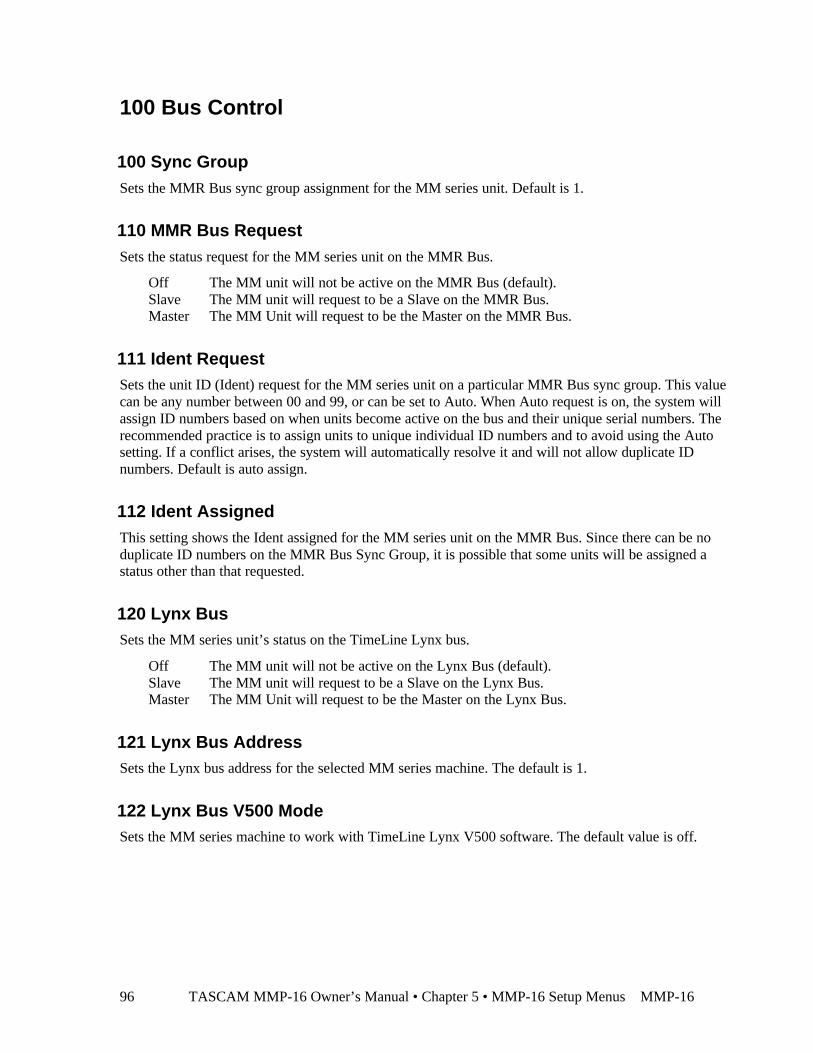
TASCAM MMP-16 Owner’s Manual • Chapter 5 • MMP-16 Setup Menus MMP-1696
100 Bus Control
100 Sync GroupSets the MMR Bus sync group assignment for the MM series unit. Default is 1.
110 MMR Bus RequestSets the status request for the MM series unit on the MMR Bus.
§ Off The MM unit will not be active on the MMR Bus (default).§ Slave The MM unit will request to be a Slave on the MMR Bus.§ Master The MM Unit will request to be the Master on the MMR Bus.
111 Ident RequestSets the unit ID (Ident) request for the MM series unit on a particular MMR Bus sync group. This valuecan be any number between 00 and 99, or can be set to Auto. When Auto request is on, the system willassign ID numbers based on when units become active on the bus and their unique serial numbers. Therecommended practice is to assign units to unique individual ID numbers and to avoid using the Autosetting. If a conflict arises, the system will automatically resolve it and will not allow duplicate IDnumbers. Default is auto assign.
112 Ident AssignedThis setting shows the Ident assigned for the MM series unit on the MMR Bus. Since there can be noduplicate ID numbers on the MMR Bus Sync Group, it is possible that some units will be assigned astatus other than that requested.
120 Lynx BusSets the MM series unit’s status on the TimeLine Lynx bus.
§ Off The MM unit will not be active on the Lynx Bus (default).§ Slave The MM unit will request to be a Slave on the Lynx Bus.§ Master The MM Unit will request to be the Master on the Lynx Bus.
121 Lynx Bus AddressSets the Lynx bus address for the selected MM series machine. The default is 1.
122 Lynx Bus V500 ModeSets the MM series machine to work with TimeLine Lynx V500 software. The default value is off.
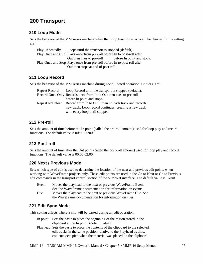
MMP-16 TASCAM MMP-16 Owner’s Manual • Chapter 5 • MMP-16 Setup Menus 97
200 Transport
210 Loop ModeSets the behavior of the MM series machine when the Loop function is active. The choices for the settingare:
§ Play Repeatedly Loops until the transport is stopped (default).§ Play Once and Cue Plays once from pre-roll before In to post-roll after
Out then cues to pre-roll before In point and stops.§ Play Once and Stop Plays once from pre-roll before In to post-roll after
Out then stops at end of post-roll.
211 Loop RecordSets the behavior of the MM series machine during Loop Record operation. Choices are:
§ Repeat Record Loop Record until the transport is stopped (default).§ Record Once Only Records once from In to Out then cues to pre-roll
before In point and stops.§ Repeat w/Unload Record from In to Out then unloads track and records
new track. Loop record continues, creating a new trackwith every loop until stopped.
212 Pre-rollSets the amount of time before the In point (called the pre-roll amount) used for loop play and recordfunctions. The default value is 00:00:05:00.
213 Post-rollSets the amount of time after the Out point (called the post-roll amount) used for loop play and recordfunctions. The default value is 00:00:02:00.
220 Next / Previous ModeSets which type of edit is used to determine the location of the next and previous edit points whenworking with WaveFrame projects only. These edit points are used in the Go to Next or Go to Previousedit commands in the transport control section of the ViewNet interface. The default value is Event.
§ Event Moves the playhead to the next or previous WaveFrame Event.See the WaveFrame documentation for information on events.
§ Cue Moves the playhead to the next or previous WaveFrame Cue. Seethe WaveFrame documentation for information on cues.
221 Edit Sync ModeThis setting affects where a clip will be pasted during an edit operation.
§ In point Sets the paste to place the beginning of the region stored in theclipboard at the In point. (default value)
§ Playhead Sets the paste to place the contents of the clipboard to the selectededit tracks in the same position relative to the Playhead as thosecontents occupied when the material was placed on the clipboard.
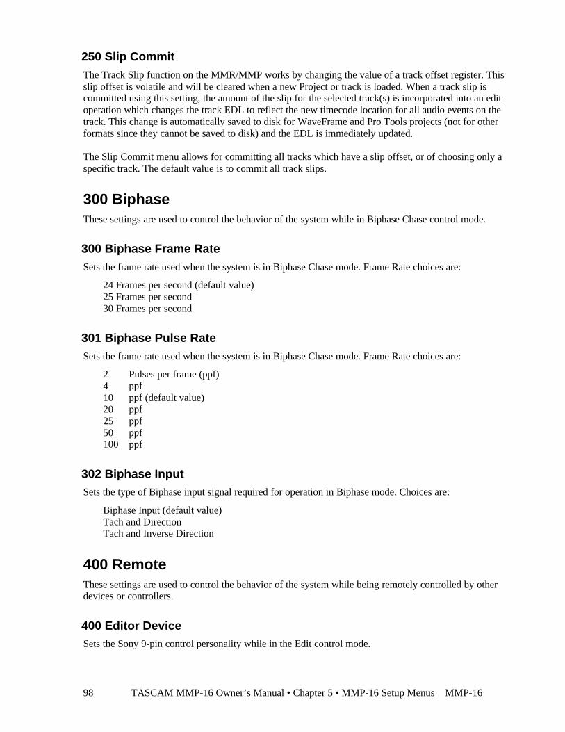
TASCAM MMP-16 Owner’s Manual • Chapter 5 • MMP-16 Setup Menus MMP-1698
250 Slip CommitThe Track Slip function on the MMR/MMP works by changing the value of a track offset register. Thisslip offset is volatile and will be cleared when a new Project or track is loaded. When a track slip iscommitted using this setting, the amount of the slip for the selected track(s) is incorporated into an editoperation which changes the track EDL to reflect the new timecode location for all audio events on thetrack. This change is automatically saved to disk for WaveFrame and Pro Tools projects (not for otherformats since they cannot be saved to disk) and the EDL is immediately updated.
The Slip Commit menu allows for committing all tracks which have a slip offset, or of choosing only aspecific track. The default value is to commit all track slips.
300 BiphaseThese settings are used to control the behavior of the system while in Biphase Chase control mode.
300 Biphase Frame RateSets the frame rate used when the system is in Biphase Chase mode. Frame Rate choices are:
§ 24 Frames per second (default value)§ 25 Frames per second§ 30 Frames per second
301 Biphase Pulse RateSets the frame rate used when the system is in Biphase Chase mode. Frame Rate choices are:
§ 2 Pulses per frame (ppf)§ 4 ppf§ 10 ppf (default value)§ 20 ppf§ 25 ppf§ 50 ppf§ 100 ppf
302 Biphase InputSets the type of Biphase input signal required for operation in Biphase mode. Choices are:
§ Biphase Input (default value)§ Tach and Direction§ Tach and Inverse Direction
400 RemoteThese settings are used to control the behavior of the system while being remotely controlled by otherdevices or controllers.
400 Editor DeviceSets the Sony 9-pin control personality while in the Edit control mode.
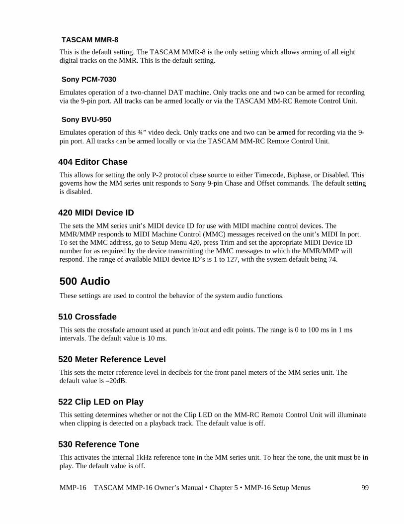
MMP-16 TASCAM MMP-16 Owner’s Manual • Chapter 5 • MMP-16 Setup Menus 99
TASCAM MMR-8
This is the default setting. The TASCAM MMR-8 is the only setting which allows arming of all eightdigital tracks on the MMR. This is the default setting.
Sony PCM-7030
Emulates operation of a two-channel DAT machine. Only tracks one and two can be armed for recordingvia the 9-pin port. All tracks can be armed locally or via the TASCAM MM-RC Remote Control Unit.
Sony BVU-950
Emulates operation of this ¾” video deck. Only tracks one and two can be armed for recording via the 9-pin port. All tracks can be armed locally or via the TASCAM MM-RC Remote Control Unit.
404 Editor ChaseThis allows for setting the only P-2 protocol chase source to either Timecode, Biphase, or Disabled. Thisgoverns how the MM series unit responds to Sony 9-pin Chase and Offset commands. The default settingis disabled.
420 MIDI Device IDThe sets the MM series unit’s MIDI device ID for use with MIDI machine control devices. TheMMR/MMP responds to MIDI Machine Control (MMC) messages received on the unit’s MIDI In port.To set the MMC address, go to Setup Menu 420, press Trim and set the appropriate MIDI Device IDnumber for as required by the device transmitting the MMC messages to which the MMR/MMP willrespond. The range of available MIDI device ID’s is 1 to 127, with the system default being 74.
500 AudioThese settings are used to control the behavior of the system audio functions.
510 CrossfadeThis sets the crossfade amount used at punch in/out and edit points. The range is 0 to 100 ms in 1 msintervals. The default value is 10 ms.
520 Meter Reference LevelThis sets the meter reference level in decibels for the front panel meters of the MM series unit. Thedefault value is –20dB.
522 Clip LED on PlayThis setting determines whether or not the Clip LED on the MM-RC Remote Control Unit will illuminatewhen clipping is detected on a playback track. The default value is off.
530 Reference ToneThis activates the internal 1kHz reference tone in the MM series unit. To hear the tone, the unit must be inplay. The default value is off.
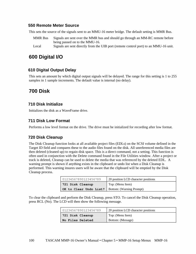
TASCAM MMP-16 Owner’s Manual • Chapter 5 • MMP-16 Setup Menus MMP-16100
550 Remote Meter SourceThis sets the source of the signals sent to an MMU-16 meter bridge. The default setting is MMR Bus.
§ MMR Bus Signals are sent over the MMR bus and should go through an MM-RC remote beforebeing passed on to the MMU-16.
§ Local Signals are sent directly from the UIB port (remote control port) to an MMU-16 unit.
600 Digital I/O
610 Digital Output DelayThis sets an amount by which digital output signals will be delayed. The range for this setting is 1 to 255samples in 1 sample increments. The default value is internal (no delay).
700 Disk
710 Disk InitializeInitializes the disk as a WaveFrame drive.
711 Disk Low FormatPerforms a low level format on the drive. The drive must be initialized for recording after low format.
720 Disk CleanupThe Disk Cleanup function looks at all available project files (EDLs) on the SCSI volume defined in theTarget ID field and compares these to the audio files found on the disk. All unreferenced media files arethen deleted (cleaned up) to regain disk space. This is a direct command, not a setting. This function isoften used in conjunction with the Delete command found in the File Utilities window. After a project ortrack is deleted, Cleanup can be used to delete the media that was referenced by the deleted EDL. Awarning prompt is shown if anything exists in the clipboard or undo list when a Disk Cleanup isperformed. This warning insures users will be aware that the clipboard will be emptied by the DiskCleanup process.
01234567890123456789 20 position LCD character positions
721 Disk Cleanup Top: (Menu Item)
OK to Clear Undo List? Bottom: (Warning Prompt)
To clear the clipboard and perform the Disk Cleanup, press STO. To cancel the Disk Cleanup operation,press RCL (No). The LCD will then show the following message.
01234567890123456789 20 position LCD character positions
721 Disk Cleanup Top: (Menu Item)
No Files Deleted Bottom: (Message)
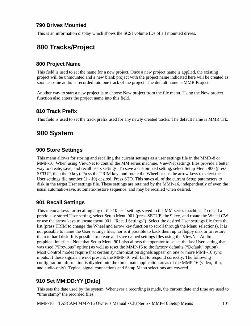
MMP-16 TASCAM MMP-16 Owner’s Manual • Chapter 5 • MMP-16 Setup Menus 101
790 Drives MountedThis is an information display which shows the SCSI volume IDs of all mounted drives.
800 Tracks/Project
800 Project NameThis field is used to set the name for a new project. Once a new project name is applied, the existingproject will be unmounted and a new blank project with the project name indicated here will be created assoon as some audio is recorded into one track of the project. The default name is MMR Project.
Another way to start a new project is to choose New project from the file menu. Using the New projectfunction also enters the project name into this field.
810 Track PrefixThis field is used to set the track prefix used for any newly created tracks. The default name is MMR Trk.
900 System
900 Store SettingsThis menu allows for storing and recalling the current settings as a user settings file in the MMR-8 orMMP-16. When using ViewNet to control the MM series machine, ViewNet settings files provide a betterway to create, save, and recall users settings. To save a customized setting, select Setup Menu 900 (pressSETUP, then the 9 key). Press the TRIM key, and rotate the Wheel or use the arrow keys to select theUser settings file number (1 - 10) desired. Press STO. This saves all of the current Setup parameters todisk in the target User settings file. These settings are retained by the MMP-16, independently of even theusual automatic-save, automatic-restore sequence, and may be recalled when desired.
901 Recall SettingsThis menu allows for recalling any of the 10 user settings saved in the MM series machine. To recall apreviously stored User setting, select Setup Menu 901 (press SETUP, the 9 key, and rotate the Wheel CWor use the arrow keys to locate menu 901, “Recall Settings”). Select the desired User settings file from thelist (press TRIM to change the Wheel and arrow key function to scroll through the Menu selections). It isnot possible to name the User settings files, nor is it possible to back them up to floppy disk or to restorethem to hard disk. It is possible to create and save named settings files using the ViewNet Audiographical interface. Note that Setup Menu 901 also allows the operator to select the last User setting thatwas used (“Previous” option) as well as reset the MMP-16 to the factory defaults (“Default” option).Most Control modes require that certain synchronization signals appear on one or more MMP-16 syncinputs. If these signals are not present, the MMP-16 will fail to respond correctly. The followingconfiguration information is divided into the three main application areas of the MMP-16 (video, film,and audio-only). Typical signal connections and Setup Menu selections are covered.
910 Set MM:DD:YY [Date]This sets the date used by the system. Whenever a recording is made, the current date and time are used to“time stamp” the recorded files.
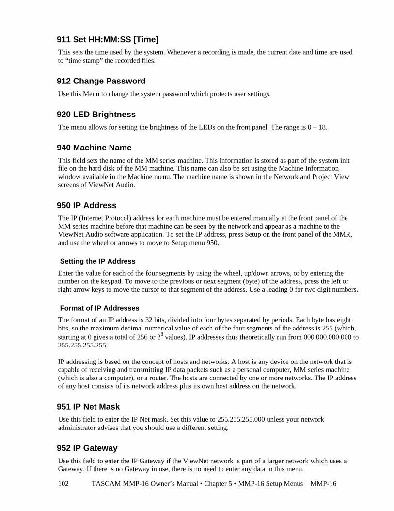
TASCAM MMP-16 Owner’s Manual • Chapter 5 • MMP-16 Setup Menus MMP-16102
911 Set HH:MM:SS [Time]This sets the time used by the system. Whenever a recording is made, the current date and time are usedto “time stamp” the recorded files.
912 Change PasswordUse this Menu to change the system password which protects user settings.
920 LED BrightnessThe menu allows for setting the brightness of the LEDs on the front panel. The range is 0 – 18.
940 Machine NameThis field sets the name of the MM series machine. This information is stored as part of the system initfile on the hard disk of the MM machine. This name can also be set using the Machine Informationwindow available in the Machine menu. The machine name is shown in the Network and Project Viewscreens of ViewNet Audio.
950 IP AddressThe IP (Internet Protocol) address for each machine must be entered manually at the front panel of theMM series machine before that machine can be seen by the network and appear as a machine to theViewNet Audio software application. To set the IP address, press Setup on the front panel of the MMR,and use the wheel or arrows to move to Setup menu 950.
Setting the IP Address
Enter the value for each of the four segments by using the wheel, up/down arrows, or by entering thenumber on the keypad. To move to the previous or next segment (byte) of the address, press the left orright arrow keys to move the cursor to that segment of the address. Use a leading 0 for two digit numbers.
Format of IP Addresses
The format of an IP address is 32 bits, divided into four bytes separated by periods. Each byte has eightbits, so the maximum decimal numerical value of each of the four segments of the address is 255 (which,starting at 0 gives a total of 256 or 28 values). IP addresses thus theoretically run from 000.000.000.000 to255.255.255.255.
IP addressing is based on the concept of hosts and networks. A host is any device on the network that iscapable of receiving and transmitting IP data packets such as a personal computer, MM series machine(which is also a computer), or a router. The hosts are connected by one or more networks. The IP addressof any host consists of its network address plus its own host address on the network.
951 IP Net MaskUse this field to enter the IP Net mask. Set this value to 255.255.255.000 unless your networkadministrator advises that you should use a different setting.
952 IP GatewayUse this field to enter the IP Gateway if the ViewNet network is part of a larger network which uses aGateway. If there is no Gateway in use, there is no need to enter any data in this menu.
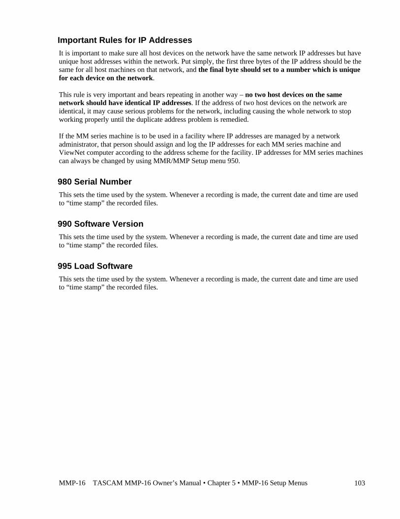
MMP-16 TASCAM MMP-16 Owner’s Manual • Chapter 5 • MMP-16 Setup Menus 103
Important Rules for IP AddressesIt is important to make sure all host devices on the network have the same network IP addresses but haveunique host addresses within the network. Put simply, the first three bytes of the IP address should be thesame for all host machines on that network, and the final byte should set to a number which is uniquefor each device on the network.
This rule is very important and bears repeating in another way – no two host devices on the samenetwork should have identical IP addresses. If the address of two host devices on the network areidentical, it may cause serious problems for the network, including causing the whole network to stopworking properly until the duplicate address problem is remedied.
If the MM series machine is to be used in a facility where IP addresses are managed by a networkadministrator, that person should assign and log the IP addresses for each MM series machine andViewNet computer according to the address scheme for the facility. IP addresses for MM series machinescan always be changed by using MMR/MMP Setup menu 950.
980 Serial NumberThis sets the time used by the system. Whenever a recording is made, the current date and time are usedto “time stamp” the recorded files.
990 Software VersionThis sets the time used by the system. Whenever a recording is made, the current date and time are usedto “time stamp” the recorded files.
995 Load SoftwareThis sets the time used by the system. Whenever a recording is made, the current date and time are usedto “time stamp” the recorded files.

TASCAM MMP-16 Owner’s Manual • Chapter 5 • MMP-16 Setup Menus MMP-16104
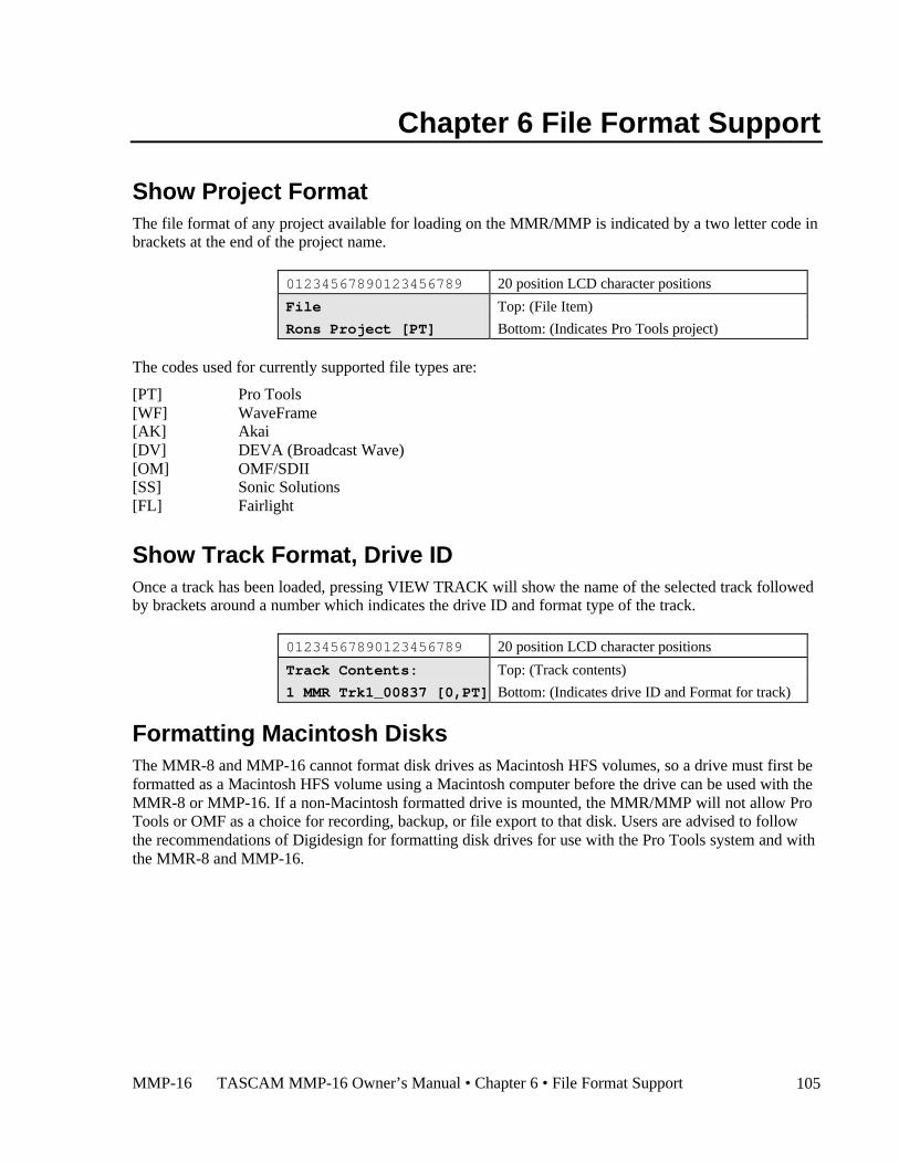
MMP-16 TASCAM MMP-16 Owner’s Manual • Chapter 6 • File Format Support 105
Chapter 6 File Format Support
Show Project FormatThe file format of any project available for loading on the MMR/MMP is indicated by a two letter code inbrackets at the end of the project name.
01234567890123456789 20 position LCD character positions
File Top: (File Item)
Rons Project [PT] Bottom: (Indicates Pro Tools project)
The codes used for currently supported file types are:
[PT] Pro Tools[WF] WaveFrame[AK] Akai[DV] DEVA (Broadcast Wave)[OM] OMF/SDII[SS] Sonic Solutions[FL] Fairlight
Show Track Format, Drive IDOnce a track has been loaded, pressing VIEW TRACK will show the name of the selected track followedby brackets around a number which indicates the drive ID and format type of the track.
01234567890123456789 20 position LCD character positions
Track Contents: Top: (Track contents)
1 MMR Trk1_00837 [0,PT] Bottom: (Indicates drive ID and Format for track)
Formatting Macintosh DisksThe MMR-8 and MMP-16 cannot format disk drives as Macintosh HFS volumes, so a drive must first beformatted as a Macintosh HFS volume using a Macintosh computer before the drive can be used with theMMR-8 or MMP-16. If a non-Macintosh formatted drive is mounted, the MMR/MMP will not allow ProTools or OMF as a choice for recording, backup, or file export to that disk. Users are advised to followthe recommendations of Digidesign for formatting disk drives for use with the Pro Tools system and withthe MMR-8 and MMP-16.
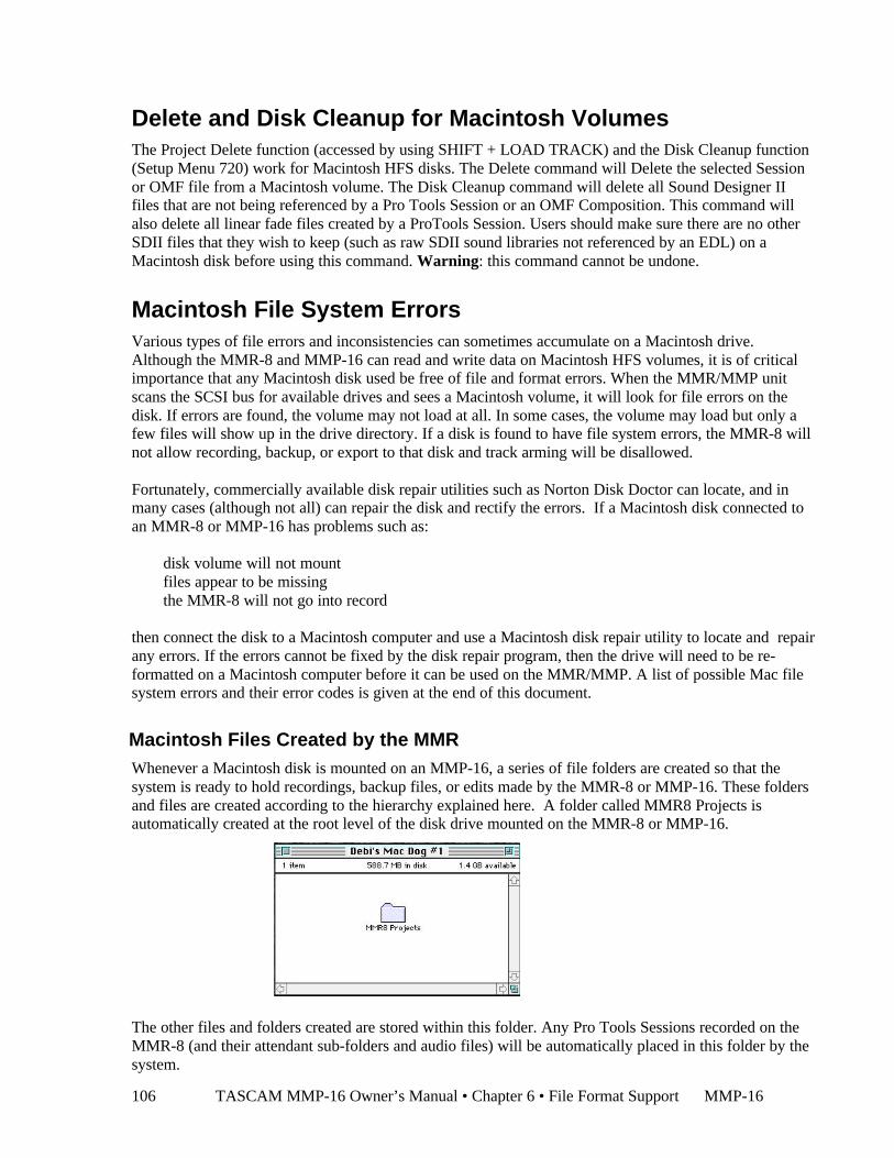
TASCAM MMP-16 Owner’s Manual • Chapter 6 • File Format Support MMP-16106
Delete and Disk Cleanup for Macintosh VolumesThe Project Delete function (accessed by using SHIFT + LOAD TRACK) and the Disk Cleanup function(Setup Menu 720) work for Macintosh HFS disks. The Delete command will Delete the selected Sessionor OMF file from a Macintosh volume. The Disk Cleanup command will delete all Sound Designer IIfiles that are not being referenced by a Pro Tools Session or an OMF Composition. This command willalso delete all linear fade files created by a ProTools Session. Users should make sure there are no otherSDII files that they wish to keep (such as raw SDII sound libraries not referenced by an EDL) on aMacintosh disk before using this command. Warning: this command cannot be undone.
Macintosh File System ErrorsVarious types of file errors and inconsistencies can sometimes accumulate on a Macintosh drive.Although the MMR-8 and MMP-16 can read and write data on Macintosh HFS volumes, it is of criticalimportance that any Macintosh disk used be free of file and format errors. When the MMR/MMP unitscans the SCSI bus for available drives and sees a Macintosh volume, it will look for file errors on thedisk. If errors are found, the volume may not load at all. In some cases, the volume may load but only afew files will show up in the drive directory. If a disk is found to have file system errors, the MMR-8 willnot allow recording, backup, or export to that disk and track arming will be disallowed.
Fortunately, commercially available disk repair utilities such as Norton Disk Doctor can locate, and inmany cases (although not all) can repair the disk and rectify the errors. If a Macintosh disk connected toan MMR-8 or MMP-16 has problems such as:
§ disk volume will not mount§ files appear to be missing§ the MMR-8 will not go into record
then connect the disk to a Macintosh computer and use a Macintosh disk repair utility to locate and repairany errors. If the errors cannot be fixed by the disk repair program, then the drive will need to be re-formatted on a Macintosh computer before it can be used on the MMR/MMP. A list of possible Mac filesystem errors and their error codes is given at the end of this document.
Macintosh Files Created by the MMRWhenever a Macintosh disk is mounted on an MMP-16, a series of file folders are created so that thesystem is ready to hold recordings, backup files, or edits made by the MMR-8 or MMP-16. These foldersand files are created according to the hierarchy explained here. A folder called MMR8 Projects isautomatically created at the root level of the disk drive mounted on the MMR-8 or MMP-16.
The other files and folders created are stored within this folder. Any Pro Tools Sessions recorded on theMMR-8 (and their attendant sub-folders and audio files) will be automatically placed in this folder by thesystem.
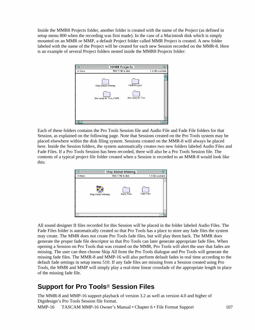
MMP-16 TASCAM MMP-16 Owner’s Manual • Chapter 6 • File Format Support 107
Inside the MMR8 Projects folder, another folder is created with the name of the Project (as defined insetup menu 800 when the recording was first made). In the case of a Macintosh disk which is simplymounted on an MMR or MMP, a default Project folder called MMR Project is created. A new folderlabeled with the name of the Project will be created for each new Session recorded on the MMR-8. Hereis an example of several Project folders nested inside the MMR8 Projects folder:
Each of these folders contains the Pro Tools Session file and Audio File and Fade File folders for thatSession, as explained on the following page. Note that Sessions created on the Pro Tools system may beplaced elsewhere within the disk filing system. Sessions created on the MMR-8 will always be placedhere. Inside the Session folders, the system automatically creates two new folders labeled Audio Files andFade Files. If a Pro Tools Session has been recorded, there will also be a Pro Tools Session file. Thecontents of a typical project file folder created when a Session is recorded to an MMR-8 would look likethis:
All sound designer II files recorded for this Session will be placed in the folder labeled Audio Files. TheFade Files folder is automatically created so that Pro Tools has a place to store any fade files the systemmay create. The MMR does not create Pro Tools fade files, but will play them back. The MMR doesgenerate the proper fade file descriptor so that Pro Tools can later generate appropriate fade files. Whenopening a Session on Pro Tools that was created on the MMR, Pro Tools will alert the user that fades aremissing. The user can then choose Skip All from the Pro Tools dialogue and Pro Tools will generate themissing fade files. The MMR-8 and MMP-16 will also perform default fades in real time according to thedefault fade settings in setup menu 510. If any fade files are missing from a Session created using ProTools, the MMR and MMP will simply play a real-time linear crossfade of the appropriate length in placeof the missing fade file.
Support for Pro Tools® Session FilesThe MMR-8 and MMP-16 support playback of version 3.2 as well as version 4.0 and higher ofDigidesign’s Pro Tools Session file format.
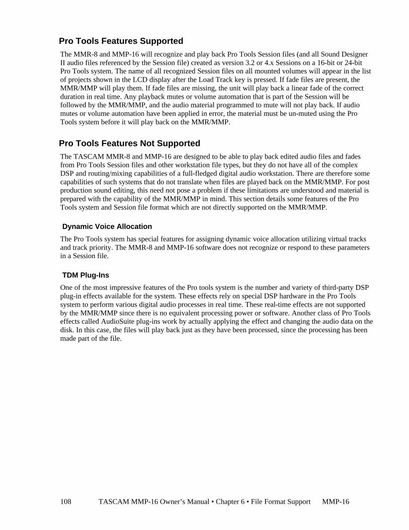
TASCAM MMP-16 Owner’s Manual • Chapter 6 • File Format Support MMP-16108
Pro Tools Features SupportedThe MMR-8 and MMP-16 will recognize and play back Pro Tools Session files (and all Sound DesignerII audio files referenced by the Session file) created as version 3.2 or 4.x Sessions on a 16-bit or 24-bitPro Tools system. The name of all recognized Session files on all mounted volumes will appear in the listof projects shown in the LCD display after the Load Track key is pressed. If fade files are present, theMMR/MMP will play them. If fade files are missing, the unit will play back a linear fade of the correctduration in real time. Any playback mutes or volume automation that is part of the Session will befollowed by the MMR/MMP, and the audio material programmed to mute will not play back. If audiomutes or volume automation have been applied in error, the material must be un-muted using the ProTools system before it will play back on the MMR/MMP.
Pro Tools Features Not SupportedThe TASCAM MMR-8 and MMP-16 are designed to be able to play back edited audio files and fadesfrom Pro Tools Session files and other workstation file types, but they do not have all of the complexDSP and routing/mixing capabilities of a full-fledged digital audio workstation. There are therefore somecapabilities of such systems that do not translate when files are played back on the MMR/MMP. For postproduction sound editing, this need not pose a problem if these limitations are understood and material isprepared with the capability of the MMR/MMP in mind. This section details some features of the ProTools system and Session file format which are not directly supported on the MMR/MMP.
Dynamic Voice Allocation
The Pro Tools system has special features for assigning dynamic voice allocation utilizing virtual tracksand track priority. The MMR-8 and MMP-16 software does not recognize or respond to these parametersin a Session file.
TDM Plug-Ins
One of the most impressive features of the Pro tools system is the number and variety of third-party DSPplug-in effects available for the system. These effects rely on special DSP hardware in the Pro Toolssystem to perform various digital audio processes in real time. These real-time effects are not supportedby the MMR/MMP since there is no equivalent processing power or software. Another class of Pro Toolseffects called AudioSuite plug-ins work by actually applying the effect and changing the audio data on thedisk. In this case, the files will play back just as they have been processed, since the processing has beenmade part of the file.
MMP-16 TASCAM MMP-16 Owner’s Manual • Chapter 6 • File Format Support 109
Voice Output Assignments
Since Pro Tools has extensive mixing capabilities, it also allows tracks to be freely assigned to variousoutputs for playback. The MMR/MMP units are designed to assign Pro Tools tracks directly to audiooutput channels on the MMR/MMP unit on a one-to-one basis and do not follow the output mapping ofPro Tools session. When editing material on Pro Tools for eventual playback on an MMR/MMP, it is bestto place the material on the track where it should play on the MMR/MMP. Track assignments can bechanged locally on the MMR/MMP and any track can be assigned to play out of any MMR/MMP channeloutput, but the default assignment when loading a Session will be to the tracks as numbered in the ProTools Session, not the voice assignment patching.
Restrictions When Using the Pro Tools Session FormatBoth the TASCAM MMR-8/MMP-16 and Digidesign Pro Tools have features for which there is noequivalent function in the other system. This leads to certain restrictions the user should be aware of whenmoving material between these two systems.
Pull Up / Pull Down
ProTools only supports a Pull Up from 30fps and a Pull Down from 29.97fps. The MMR/MMP supportsthese and other frame rates. If something other than the standard frame rates or the above mentioned pull-up / pull-downs are set in a recording made on the MMR-8, the ProTools Session file created will notsave that property in the Session file since that format has no way to store this data.
Frame and Sample Rates in Tape Mode
When creating TapeMode ProTools projects, be sure to pick a supported frame rate/sample ratecombination (see above) before recording. Once the TapeMode Session file has been created,altering the frame rate will cause the Session to be regarded as a regular Non-Destructive Session and nota TapeMode Session. This is due to the fact that the Session format does not store sample based starttimes, but frame based start times. TapeMode very much depends on the Project or Session start time,which cannot be altered if TapeMode capability is to be retained.
Limitations on Number of Tracks
ProTools 4.2 supports a maximum of 43 tracks per Session. This track number limitation affects howmany times tracks may be unloaded on the MMR-8/MMP-16. Once the maximum number of tracks hasbeen reached the unit will no longer be able to unload tracks for that Session. Note that this will alsoaffect the Loop Mode (menu 211) when the Repeat w/Unload option is chosen. Once the unload limit isreached, the transport will stop with an error message indicating that the maximum number of tracks hasbeen reached. The same restriction will prevent exporting WaveFrame Projects or OMF Compositions toProTools if the maximum number of channels is exceeded. A future software revision of the MMR/MMPwill use the alternate tracks feature of ProTools to permit unlimited unloading of tracks and eliminate thisrestriction.
Session Start Time Restrictions
When recording additional audio on existing projects created originally with ProTools, audio punch-inbefore the start time defined in the project is not allowed. Pro Tools has the same restriction. If it isnecessary to punch in on a track before the Session start time, use the Pro Tools system to re-set thesession start time as appropriate. The MMR-8 has no provision to set the start time, except for tape mode.Non-TapeMode ProTools sessions generated on the MMR-8 always use a start time of 0 and hence willhave no punch in restriction. A TapeMode project has its own TapeMode start time for all formats, set inmenu 230.
TASCAM MMP-16 Owner’s Manual • Chapter 6 • File Format Support MMP-16110
Using TapeMode with ProTools Sessions
The MMR-8 has two record modes, Non-Destructive and TapeMode. Non-Destructive Record Modeworks the same way as Pro Tools in that each recording makes a new audio file on the disk and does notover-write any existing material. In TapeMode, each track is considered to be a single continuous audiofile and successive recordings will destructively over-write any existing audio on the same track when apunch-in is made. This is a useful way to record on the MMR-8 because it makes the most efficient use ofdisk space when recording mix tracks that will have a lot of record punch-in and out passes over the samepart of the track. It is also more efficient in operation and will make the MMR-8 much less susceptible to“media too slow” errors when punching in and out across many tracks simultaneously, particularly whenrecording 24-bit files.Although Pro Tools has a destructive record mode, it does not work the same way as the MMRTapeMode, so some of the rules for using TapeMode on the MMR-8 do not have an equivalent on the ProTools system. It is important to understand some of the consequences of using TapeMode when recordingin the Pro Tools Session file format, since there are differences between the way TapeMode recordingworks with WaveFrame files and how it works with Pro Tools Sessions.
If the Record Mode (menu 200) is set to TapeMode when recording a Pro Tools Session, the MMR willautomatically allocate all disk drive space between the TapeMode Start Time (menu 230) and the timewhere audio is recorded in each track. For example, in a TapeMode Session with a TapeMode Start timeof 01:00:00:00, if audio is recorded beginning at one hour, then only the audio actually recorded will takeup space on the disk. If the TapeMode start time is set to one hour and the current time location of theMMR-8 is set to two hours and recording begins, the system will automatically allocate one track-hour ofdisk space for each track in record. It is possible to verify that this is so by checking the Free Time on thedisk (press Shift + 3). This behavior is different from the way WaveFrame TapeMode projects work. TheWaveFrame file system allows continuous files to have “holes” in them but still be considered a singlefile. The Macintosh Hierarchical File System has no way to do this, so a recording made after the starttime of a TapeMode Session will cause the system to automatically see all disk space between theTapeMode start time and the last bit of audio recorded on a particular track as being allocated to thataudio file. This means that it is very important to set an appropriate start time when using TapeMode tomake sure disk space is not wasted or used unnecessarily. For example, successive reels of a film willquite often carry a time code hour number that is the same as the reel number. If this method is being usedand reel 3 is being recorded (mixed) to an MMR-8, be sure the time code for the TapeMode start time isset to 03:00:00:00 and not to 01:00:00:00, or the disk may show that it is full immediately as soon asrecording is started at the beginning of the reel (at the 03:00:00:00 time code) since all space between onehour and three hours is allocated for the recording on all armed tracks. If this happens in error, you musttake the disk to a Macintosh computer and delete the audio files to regain use of the allocated disk space.A future version of the MMR-8 will allow these files to be deleted by the MMR-8 using the Disk Cleanupfunction, but this does not yet work for Macintosh disks in version 2.0.
Another distinction between the file system of Macintosh disks versus WaveFrame disks is that Mac disksmake different data block sizes on different volumes, depending on the capacity of the disk, whereas theWaveFrame file system has a fixed data block size. One effect of this is that when a backup is made of aPro Tools TapeMode Session, the Session created will only be a TapeMode Session if made to a diskwhich is formatted with exactly the same data block size, otherwise it will be backed up as a Non-Destructive Record Mode project.
MMP-16 TASCAM MMP-16 Owner’s Manual • Chapter 6 • File Format Support 111
Pro Tools Volume and Mute AutomationThe MMR-8 and MMP-16 support Digidesign Pro Tools volume (gain) and mute automation data onplayback.
Volume AutomationThe MMP-16 software supports playback of volume automation inserted in the Digidesign Pro Toolssystem. Pro Tools volume automation allows an audio track to have a volume overlay which determinesthe audio gain at user-specified break points on the track. The slope defined by the line betweenbreakpoints will translate as a change in audio level over time as the track is played. There is no capabilityto perform direct editing of volume automation data or recording of volume automation data on the MMseries unit.
Volume automation data will always be played if present in the track. MM series units will alwaysfaithfully play the track in the same way as if the track were being played on a Pro Tools system. If trackswhich contain volume automation data are edited using the edit capabilities of the MM series unit, theautomation data will always be included in the edit operation. Volume automation can only be disabledusing a Pro Tools system.
Mute AutomationThe MMP-16 software supports playback of mute automation data inserted using the Digidesign ProTools system. Pro Tools Mute Automation allows an audio track to have a volume overlay whichdetermines segments of the audio track where audio gain will be muted (attenuated) between user-specified break points on the track. There is no capability to perform direct editing of mute automationdata or recording of mute automation data on the MM series unit.
Mute automation data will always be played if present in the track. The MM series unit will alwaysfaithfully play the track in the same way as if the track were being played on a Pro Tools system. If trackswhich contain mute automation data are edited using the edit capabilities of the MM series unit, the muteautomation data will always be included in the edit operation. Mute automation can only be disabledusing a Pro Tools system.
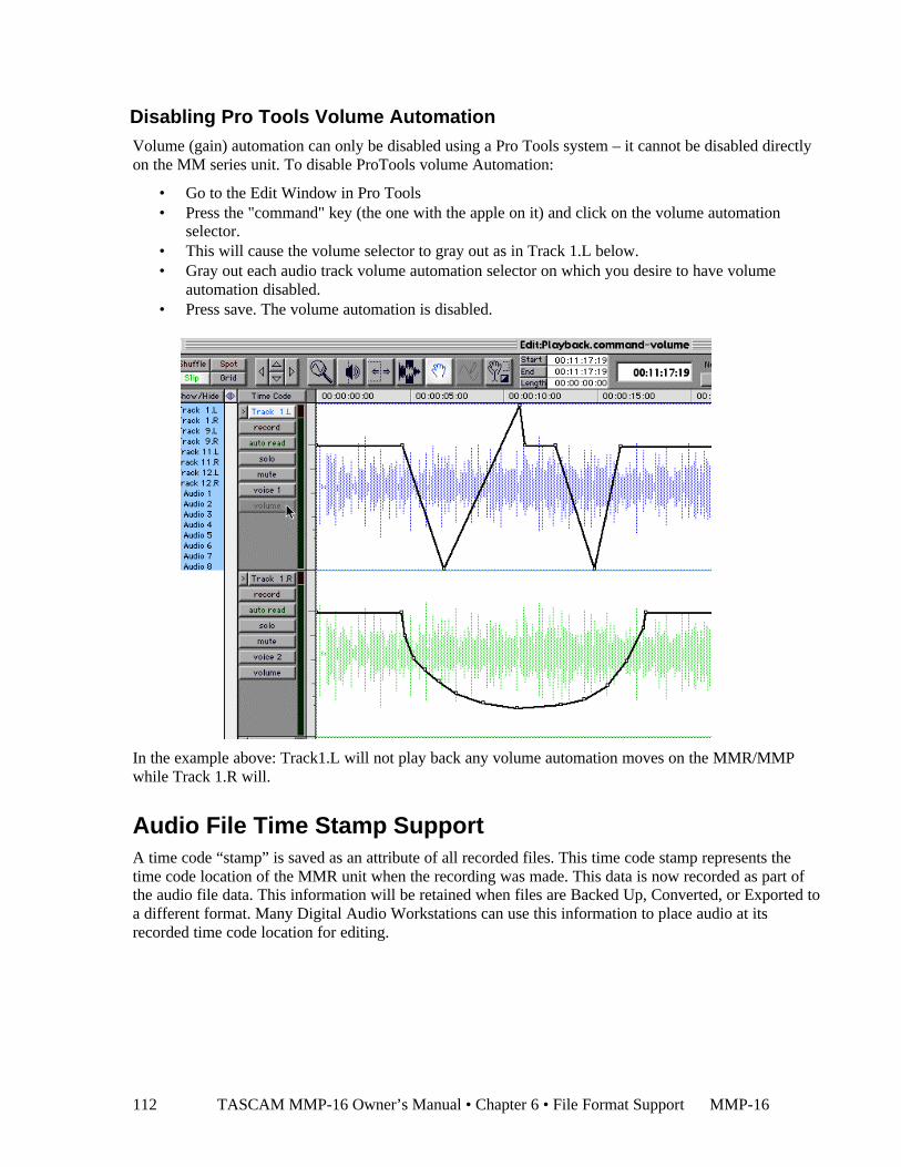
TASCAM MMP-16 Owner’s Manual • Chapter 6 • File Format Support MMP-16112
Disabling Pro Tools Volume AutomationVolume (gain) automation can only be disabled using a Pro Tools system – it cannot be disabled directlyon the MM series unit. To disable ProTools volume Automation:
• Go to the Edit Window in Pro Tools• Press the "command" key (the one with the apple on it) and click on the volume automation
selector.• This will cause the volume selector to gray out as in Track 1.L below.• Gray out each audio track volume automation selector on which you desire to have volume
automation disabled.• Press save. The volume automation is disabled.
In the example above: Track1.L will not play back any volume automation moves on the MMR/MMPwhile Track 1.R will.
Audio File Time Stamp SupportA time code “stamp” is saved as an attribute of all recorded files. This time code stamp represents thetime code location of the MMR unit when the recording was made. This data is now recorded as part ofthe audio file data. This information will be retained when files are Backed Up, Converted, or Exported toa different format. Many Digital Audio Workstations can use this information to place audio at itsrecorded time code location for editing.

MMP-16 TASCAM MMP-16 Owner’s Manual • Chapter 6 • File Format Support 113
AIFF File SupportPro Tools and OMF EDLs may reference standard AIFF (Audio Interleaved File Format) files forplayback or file utility (export) operations. To be recognized, these audio files must end in one of thefollowing suffixes: .aiff, .AIFF, .aif, or .AIF. No mixed case suffixes may be used (e.g. Aiff). Both AIFFfiles and Sound Designer II (SDII) files can be recognized and played in the same EDL, even in the sametrack. Note that the MM series machines will only read or play back AIFF files, and will not export orrecord to the AIFF format. If a Pro Tools track containing AIFF files is loaded, any new recording madeto that track on the MMR-8 will be made in the SD II format.
To properly play back on the MM series unit, the file which has the .aiff suffix must actually be a realAIFF audio file. On the Pro Tools system, a Macintosh system file identifier is used by the software tounderstand the true identity of a file. Thus, if a Sound Designer II file is erroneously named xxxx.aiff, thePro Tools application will understand that it is actually an SDII file and will play it back correctly. This isa service provided by the Macintosh operating system. This is not the case for an MM series machine. If afile which is not an actual AIFF audio file is named xxxx.aiff, the MM unit will try to play it as a trueAIFF audio file. The result will be “garbage” audio because of the difference between the actual file type(e.g. SD II) and the .aiff file that the MM series machine is attempting to play. File names are in importantin this regard, particularly the suffix after a period. Do not rename files without regard to this fact.
OMF FilesThe TASCAM MM Series machines can playback and export OMF composition (EDL) files whichreference external Sound Designer II or AIFF audio files. As of MM software Version 4.0, only sampleaccurate OMF files conforming to version 1.0 of the OMF specification can be played or exported. To berecognized by the MM series machines as a valid OMF file, it is required that the OMF compositionfollow the naming convention xxx.omf, where xxx is any file name, and the suffix .omf is all lower case.Files which do not have the .omf suffix will not be recognized as valid OMF files and will not bedisplayed in the list of available files for loading or file utility operations. Frame accurate exports such asthose created by the Avid Media Composer are not directly supported. For more information on workingwith OMF files and moving files between OMF compliant applications and the TASCAM MM seriesmachines, see the technical support page on the TimeLine web site at http://www.timelinevista.com.
Zaxcom DEVA Broadcast Wave File SupportTASCAM MM Series units support playback of Projects and audio files created on the Zaxcom DEVAhard disk recorder. This is a field recorder which records digital audio to an internal hard drive and canimmediately mirror recordings to an external SCSI device such as an Iomega Jaz disk. The MMR/MMPcan read DEVA files which have been recorded as mono sound files in the Broadcast Wave format to anexternal SCSI drive formatted as a DOS volume. Only DEVA files recorded in precisely this way can beread by the MMR/MMP. Polyphonic sound files (stereo or more tracks interleaved) can not be read, norcan Sound Designer II files recorded to a DOS disk. Projects and Track Names of files recorded on aDEVA unit will show the designation [DV] at the end of the name when it is displayed in theMMR/MMP LCD window. Support is also provided for Export of DEVA files to the WaveFrame, ProTools, and OMF/SDII formats.
TASCAM MMP-16 Owner’s Manual • Chapter 6 • File Format Support MMP-16114
DEVA Files Naming ConventionsAudio files created by the Zaxcom DEVA hard disk field recorder can be played on the TASCAM MMSeries machines. These must be in the EBU standard Broadcast Wave format on a DOS-FAT16 formatteddisk in a directory labeled /ZFILES. The name of the DEVA track files must conform to the namingconventions used by the DEVA recorder. The format is six characters, followed by either a dash orunderscore, followed by a track number (which must be 1, 2, 3, or 4), followed by the .BWF suffix. Forexample: take17_1.BWF or take17-1.BWF. Previous to Version 4.0, only the underscore character wasrecognized but the Version 4.0 software adds support for names using a dash as well.
Akai DD-8 SupportThe MMP-16 provides support for the Akai DD-8 digital dubber and other Akai products which use theidentical disk file systems and audio formats. These include the Akai DR-8, DR-16, and DD-1500.Support is limited to playback of Akai files and export of Akai files to WaveFrame, Pro Tools, andOMF/SDII formats. Support does not include recording in the Akai format on the MMR-8. To identifyfiles in the Akai format, the MMR/MMP will show [AK] at the end of any Akai Project or Track namewhen these names are displayed in the LCD.
PlaybackPlayback of Projects created on the Akai DD-8 digital disk recorder is now supported on the MMR-8 andMMP-16. This includes audio and projects created on the original DD-8 format as well as the newer DD-Plus format using either 16-bit or 24-bit audio files. All files recorded on an Akai DD-8 will play on theMMR/MMP, with the following exceptions:1) The Akai DD-8 20-bit recording mode is not supported on the MMR/MMP.2) The MMR/MMP do not support playback of audio files recorded at 96kHz sample rate.
ExportAkai DD-8 format projects can be exported to WaveFrame, Pro Tools, and OMF/SDII formats on theMMR-8 and MMP-16. To Export an Akai file to one of these other formats, first press LOAD TRACKand scroll through the display until it shows the name of the desired Akai file (the end of the file namewill show [AK] when an Akai file is recognized). Then press SHIFT+SLIP (Backup) to show the BackupMenus. Scroll through the menus and choose either WaveFrame Export, Pro Tools Export, or OMFExport and use the normal export procedure. The Project file (EDL) and audio files will be copied to thedesignated SCSI target device in the format specified. Files can not be exported from any other formatinto the Akai format because the MMR/MMP do not currently support writing the Akai format.
Editing File Formats not Written by The MM SeriesAkai DD-8, Sonic Solutions, Failright, and DEVA files can be edited on the MMR/MMP, but all edits areheld in RAM memory only and not written back to the disk. This is because the MMR-8 and MMP-16 donot write these formats. Edits in these formats will not be retained in the Project EDL.
MMP-16 TASCAM MMP-16 Owner’s Manual • Chapter 6 • File Format Support 115
Sonic Solutions File SupportSoftware for the MMR-8 and MMP-16 provides support for files created on the Sonic Studio workstationfrom Sonic Solutions. The Sonic Studio digital audio workstation uses a proprietary disk file system, aspecially modified version of the AIFF audio format, and a proprietary EDL format. Sonic Solutions is inthe process of moving toward using the newest version of Apple’s Hierarchical File System instead oftheir proprietary Media Optimized File System (MOFS). For this reason, TASCAM supports Sonic audiomedia files and EDLs only after they have been copied to a Macintosh HFS formatted disk volume, andwill not recognize a Sonic MOFS volume directly. The MMR/MMP system will only read Sonic filescopied to a Macintosh HFS volume, and does not write Sonic audio or EDL files.
Using Sonic LightspeedThe preferred method for copying Sonic files to a Macintosh HFS volume is by using Sonic’s Lightspeedprogram. Lightspeed enables Sonic MOFS volumes to be mounted on the Mac SCSI bus and accessed onthe Macintosh desktop. While on the Mac SCSI bus, the Sonic Studio system cannot record to this MOFSdrive. Lightspeed in this case is only used as a means to transfer files from the MOFS volume to the Macvolume. The Lightspeed Toolkit program and a Macintosh system extension called Sonic Lightspeed areavailable from Sonic Solutions.
To copy Sonic files from the MOFS volume to the Mac HFS volume using Lightspeed, unmount theSonic MOFS volume from the Sonic SCSI chain and mount it on the Mac SCSI chain. If the Lightspeedapplication and system extension are properly installed, the MOFS drive should mount automatically onthe Macintosh. If it does not mount automatically run the Lightspeed Toolkit program, select the drive tobe mounted and click on "Mount".
Drag the root folder of the MOFS drive onto the root folder of the Mac formatted drive. Since the SonicEDL is dependent on the full path name to a file, do not copy a sub folder or file from the MOFS volume.Do not choose a target folder on the Mac drive - drop the file onto the drive itself (root folder). Once thefile is on the Macintosh HFS volume, it can be recognized directly by the MMR-8 or MMP-16 unit.
Sonic SSP, USP, and HD System SupportOver the years, Sonic has shipped several different audio processor cards (SSP, USP, and HD) for theirSonic Studio system. The MMR/MMP only support 16-bit files from Sonic SSP-based systems. Both 16-and 24-bit files are supported for Sonic USP- and HD-based systems.
Sonic Fade FilesThe Sonic Studio system can play various types of complex fades in real time. The MMR/MMP will playany non-rendered fades as linear fades of the length specified by the EDL, but these units cannotreproduce complex fade types unless they are rendered in advance by the Sonic system. The MMR/MMPwill always play a linear fade for all non-rendered fades.
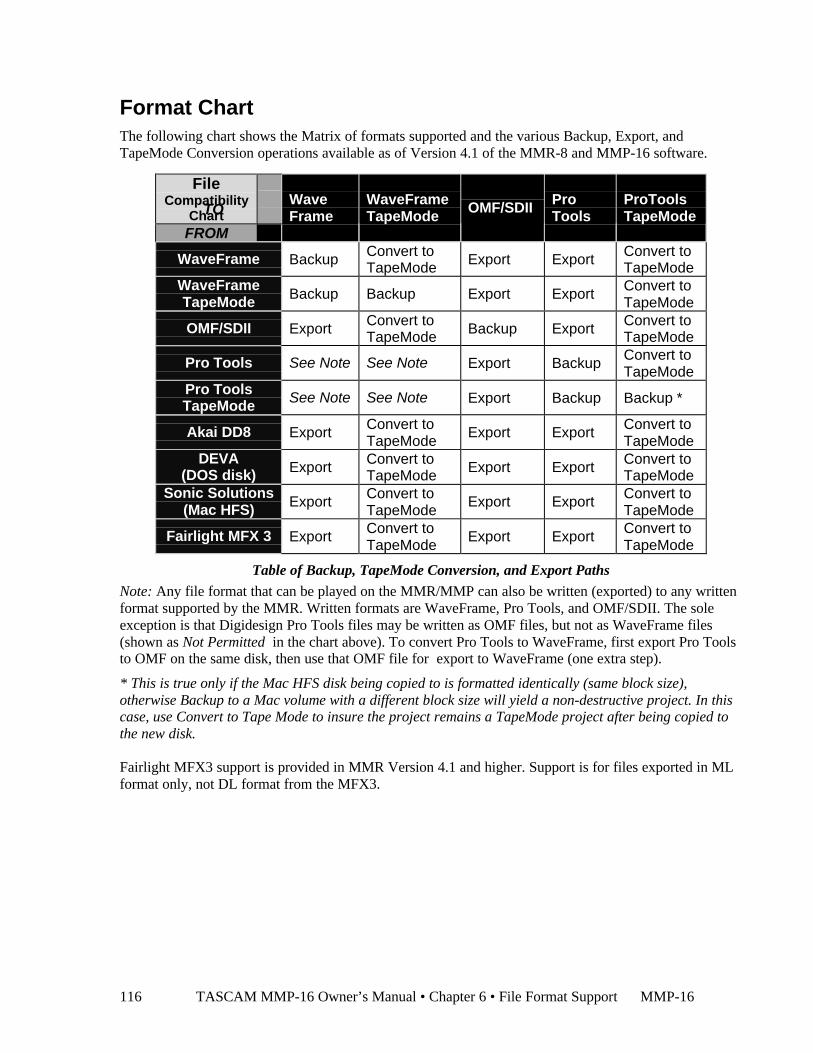
TASCAM MMP-16 Owner’s Manual • Chapter 6 • File Format Support MMP-16116
Format ChartThe following chart shows the Matrix of formats supported and the various Backup, Export, andTapeMode Conversion operations available as of Version 4.1 of the MMR-8 and MMP-16 software.
FileCompatibility
ChartFROM
WaveFrame
WaveFrameTapeMode OMF/SDII Pro
ToolsProToolsTapeMode
WaveFrame Backup Convert toTapeMode Export Export Convert to
TapeModeWaveFrameTapeMode Backup Backup Export Export Convert to
TapeMode
OMF/SDII Export Convert toTapeMode Backup Export Convert to
TapeMode
Pro Tools See Note See Note Export Backup Convert toTapeMode
Pro ToolsTapeMode See Note See Note Export Backup Backup *
Akai DD8 Export Convert toTapeMode
Export Export Convert toTapeMode
DEVA(DOS disk) Export Convert to
TapeMode Export Export Convert toTapeMode
Sonic Solutions(Mac HFS) Export Convert to
TapeModeExport Export Convert to
TapeMode
Fairlight MFX 3 Export Convert toTapeMode
Export Export Convert toTapeMode
Table of Backup, TapeMode Conversion, and Export Paths
Note: Any file format that can be played on the MMR/MMP can also be written (exported) to any writtenformat supported by the MMR. Written formats are WaveFrame, Pro Tools, and OMF/SDII. The soleexception is that Digidesign Pro Tools files may be written as OMF files, but not as WaveFrame files(shown as Not Permitted in the chart above). To convert Pro Tools to WaveFrame, first export Pro Toolsto OMF on the same disk, then use that OMF file for export to WaveFrame (one extra step).
* This is true only if the Mac HFS disk being copied to is formatted identically (same block size),otherwise Backup to a Mac volume with a different block size will yield a non-destructive project. In thiscase, use Convert to Tape Mode to insure the project remains a TapeMode project after being copied tothe new disk.
Fairlight MFX3 support is provided in MMR Version 4.1 and higher. Support is for files exported in MLformat only, not DL format from the MFX3.
TO

MMP-16 TASCAM MMP-16 Owner’s Manual • Chapter 6 • File Format Support 117
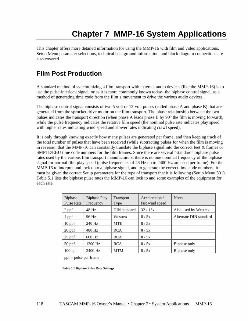
TASCAM MMP-16 Owner’s Manual • Chapter 7 • System Applications MMP-16118
Chapter 7 MMP-16 System Applications
This chapter offers more detailed information for using the MMP-16 with film and video applications.Setup Menu parameter selections, technical background information, and block diagram connections arealso covered.
Film Post Production
A standard method of synchronizing a film transport with external audio devices (like the MMP-16) is touse the pulse-interlock signal, or as it is more commonly known today--the biphase control signal, as amethod of generating time code from the film’s movement to drive the various audio devices.
The biphase control signal consists of two 5 volt or 12-volt pulses (called phase A and phase B) that aregenerated from the sprocket drive motor on the film transport. The phase relationship between the twopulses indicates the transport direction (when phase A leads phase B by 90° the film is moving forward),while the pulse frequency indicates the relative film speed (the nominal pulse rate indicates play speed,with higher rates indicating wind speed and slower rates indicating crawl speed).
It is only through knowing exactly how many pulses are generated per frame, and then keeping track ofthe total number of pulses that have been received (while subtracting pulses for when the film is movingin reverse), that the MMP-16 can constantly translate the biphase signal into the correct feet & frames orSMPTE/EBU time code numbers for the film frames. Since there are several “standard” biphase pulserates used by the various film transport manufacturers, there is no one nominal frequency of the biphasesignal for normal film play speed (pulse frequencies of 48 Hz up to 2400 Hz are used per frame). For theMMP-16 to interpret and lock onto a biphase signal, and to generate the correct time code numbers, itmust be given the correct Setup parameters for the type of transport that it is following (Setup Menu 301).Table 5.1 lists the biphase pulse rates the MMP-16 can lock to and some examples of the equipment foreach rate.
BiphasePulse Rate
Biphase PlayFrequency
TransportType
Acceleration /fast wind speed
Notes
2 ppf 48 Hz DIN standard 32 / 15x Also used by Westrex
4 ppf 96 Hz Westrex 8 / 5x Alternate DIN standard
10 ppf 240 Hz MTE 8 / 5x
20 ppf 480 Hz RCA 8 / 5x
25 ppf 600 Hz RCA 8 / 5x
50 ppf 1200 Hz RCA 8 / 5x Biphase only
100 ppf 2400 Hz MTM 8 / 5x Biphase only
ppf = pulse per frame
Table 5.1 Biphase Pulse Rate Settings
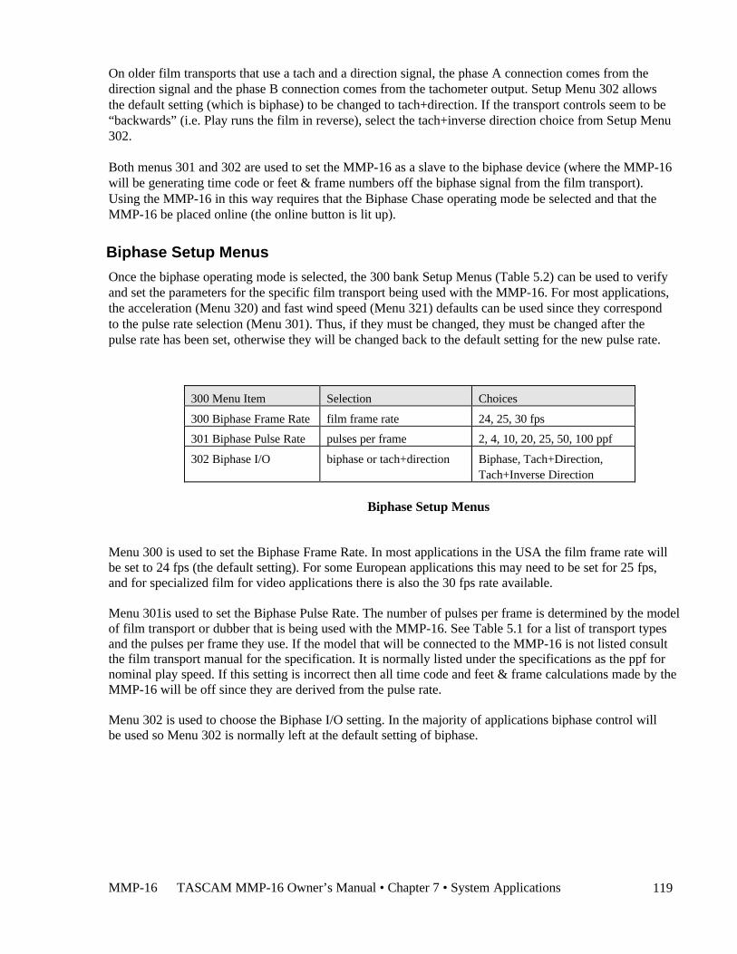
MMP-16 TASCAM MMP-16 Owner’s Manual • Chapter 7 • System Applications 119
On older film transports that use a tach and a direction signal, the phase A connection comes from thedirection signal and the phase B connection comes from the tachometer output. Setup Menu 302 allowsthe default setting (which is biphase) to be changed to tach+direction. If the transport controls seem to be“backwards” (i.e. Play runs the film in reverse), select the tach+inverse direction choice from Setup Menu302.
Both menus 301 and 302 are used to set the MMP-16 as a slave to the biphase device (where the MMP-16will be generating time code or feet & frame numbers off the biphase signal from the film transport).Using the MMP-16 in this way requires that the Biphase Chase operating mode be selected and that theMMP-16 be placed online (the online button is lit up).
Biphase Setup Menus
Once the biphase operating mode is selected, the 300 bank Setup Menus (Table 5.2) can be used to verifyand set the parameters for the specific film transport being used with the MMP-16. For most applications,the acceleration (Menu 320) and fast wind speed (Menu 321) defaults can be used since they correspondto the pulse rate selection (Menu 301). Thus, if they must be changed, they must be changed after thepulse rate has been set, otherwise they will be changed back to the default setting for the new pulse rate.
300 Menu Item Selection Choices
300 Biphase Frame Rate film frame rate 24, 25, 30 fps
301 Biphase Pulse Rate pulses per frame 2, 4, 10, 20, 25, 50, 100 ppf
302 Biphase I/O biphase or tach+direction Biphase, Tach+Direction,Tach+Inverse Direction
Biphase Setup Menus
Menu 300 is used to set the Biphase Frame Rate. In most applications in the USA the film frame rate willbe set to 24 fps (the default setting). For some European applications this may need to be set for 25 fps,and for specialized film for video applications there is also the 30 fps rate available.
Menu 301is used to set the Biphase Pulse Rate. The number of pulses per frame is determined by the modelof film transport or dubber that is being used with the MMP-16. See Table 5.1 for a list of transport typesand the pulses per frame they use. If the model that will be connected to the MMP-16 is not listed consultthe film transport manual for the specification. It is normally listed under the specifications as the ppf fornominal play speed. If this setting is incorrect then all time code and feet & frame calculations made by theMMP-16 will be off since they are derived from the pulse rate.
Menu 302 is used to choose the Biphase I/O setting. In the majority of applications biphase control willbe used so Menu 302 is normally left at the default setting of biphase.
TASCAM MMP-16 Owner’s Manual • Chapter 7 • System Applications MMP-16120
MMP-16 Film Connections
Although the MMP-16 can only be controlled by one film transport bus at a time, there are four filmtransport connections (biphase input) on the UI/B card on the rear panel. These connections allow a singleMMP-16 to be switched between up to four projection/mix down rooms when it is placed into a mainmachine room. The biphase input that the MMP-16 follows is set using the Sync Group menu 100. Thefour inputs are grouped together in the lower part of the UI/B card and are numbered 1 - 4 (top to bottom)to match Sync Groups 1 - 4 (selected through menu 100).
All biphase connectors use standard 6-pin modular telephone plugs (RJ12, the same type used on3-line telephone systems) so that up to 1,000 feet of standard 6-wire phone wiring can be run to
the various film transports. A terminal strip (or a 6-wire surface mount jack) can be used to adapt the filmtransport connector wiring to the MMP-16 wiring. These connections are normally done for postproduction final mixing sessions. Not intended for public telecommunications network connection.
As in all uses of the MMP-16, the Lynx and/or MMR buses can be used by the MMP-16 to control anynumber of additional audio and video equipment even though that MMP-16 is being controlled by thefilm transport.
Video Post ProductionIn video post production the MMP-16 is typically slaved to a video tape recorder. In this use the VTR’stime code output is the time code reference for the MMP-16. If the VTR is connected to a house syncsignal, then the MMP-16 should also be connected to house sync (through the Video In connector) andshould use that signal as the frame reference. In lieu of house sync, the VTR’s video output wouldconnect to the MMP-16’s Video In for the frame reference source. The MMP-16, although time codeslaved to the VTR, typically also functions as a master for any other audio devices on the Lynx and/orMMR buses.
The Lynx Bus
The Lynx Bus is an asynchronous communications bus that transmits a frame clock as well as time codeand motion commands between the MMP-16 and other devices using an RS-422 serial communicationsbus operating at 38.4 KBaud. Up to 1,000 feet of cabling can be used in the bus system with each deviceconnecting via 9-pin D-sub connectors. All that is required to build-up a Lynx bus is to daisy-chain eachLynx bus device to the next one in line along with a separate house sync connection. Each Lynx-2 boxhas two Lynx bus loop-through connections just like each MMP-16. A Lynx-2 interface is necessary toconnect each remote controllable audio or video device to the Lynx bus. A Lynx Keyboard Control UnitKCU can also be connected directly to the Lynx bus to allow independent and grouped remote control ofup to six Lynx bus connected machines. For more information, see Chapter 5 MMP-16 Setup Menus.
MMP-16 TASCAM MMP-16 Owner’s Manual • Chapter 8 • Maintenance and Service 121
Chapter 8 Maintenance & Service
The MMP-16 requires little maintenance other than ensuring adequate airflow through the interior of theunit. Do not use alcohol or other common studio chemical cleaners on the front panel keys.The rear panel maintenance is to vacuum and/or brush off the fan opening area of the power supply if abuild-up of dust occurs.
MMP Output Level Calibrations
Use the following procedure to calibrate the MMP-16 Output Converter board (MOC). It is assumed thatan electronics technician who has experience operating audio measurement equipment is performing thecalibration.
The following equipment is required to perform calibration adjustments:
1. A Low distortion, accurate balanced input/output audio analyzer/generator (Audio Precision System2 or equivalent). A digital multi-meter with AC rms volts measurement capability, in conjunctionwith a function generator with a sine wave output as a signal source may also be used. However, theAP equipment will provide more accurate measurements, and the settings/displays will be in theproper units
2. Plastic Potentiometer Adjustment screwdriver/tweaker.
3. Output cables compatible with the MMP-16 analog Audio Out connectors (equivalent to TASCAMDA-88 analog audio cables).
The MMP-16 has a built-in 1 kHz oscillator to check that the output levels are calibrated. To check theoutput levels, select Setup Menu 530 and select the 1 kHz setting. Press STO to turn on the internaloscillator and then press the Play key on the front panel. Measure the output levels and verify that theymatch the calibration settings (+4 dBu nominal=1.228Vrms, measured at XLR pin 2(+) and 3(-) pins). Ifcalibration is required continue to the MOC Calibration Procedure.
MOC Calibration ProcedureFollow this step-by-step procedure to calibrate the MMP-16 Output Converters (MOC).
1. Turn off power and remove the top cover of the MMP.
2. Connect the audio analyzer input to the Output connector at the rear of the MMP.
3. Turn on the MMP. Wait for the software to load.
4. Generate the MOC calibration tone, a 1 kHz, -20 dBFS (of the digital bus) sine wave. To do this,Press SETUP, and go to menu 530 by turning the Wheel. Press TRIM then turn the Wheel to selectthe 1 kHz tone. Press STO to enable generation of the tone. Press the PLAY (>) switch to start tonegeneration.
5. Set up the audio analyzer input to measure the output level on Output channel 1. Standard Calibrationlevel is digital full scale = +24 dBu. Pot adjustment range is digital full scale = +17 dBu to +25dBu.(If there are special level requirements, those levels must be substituted for the levels in thefollowing steps.)
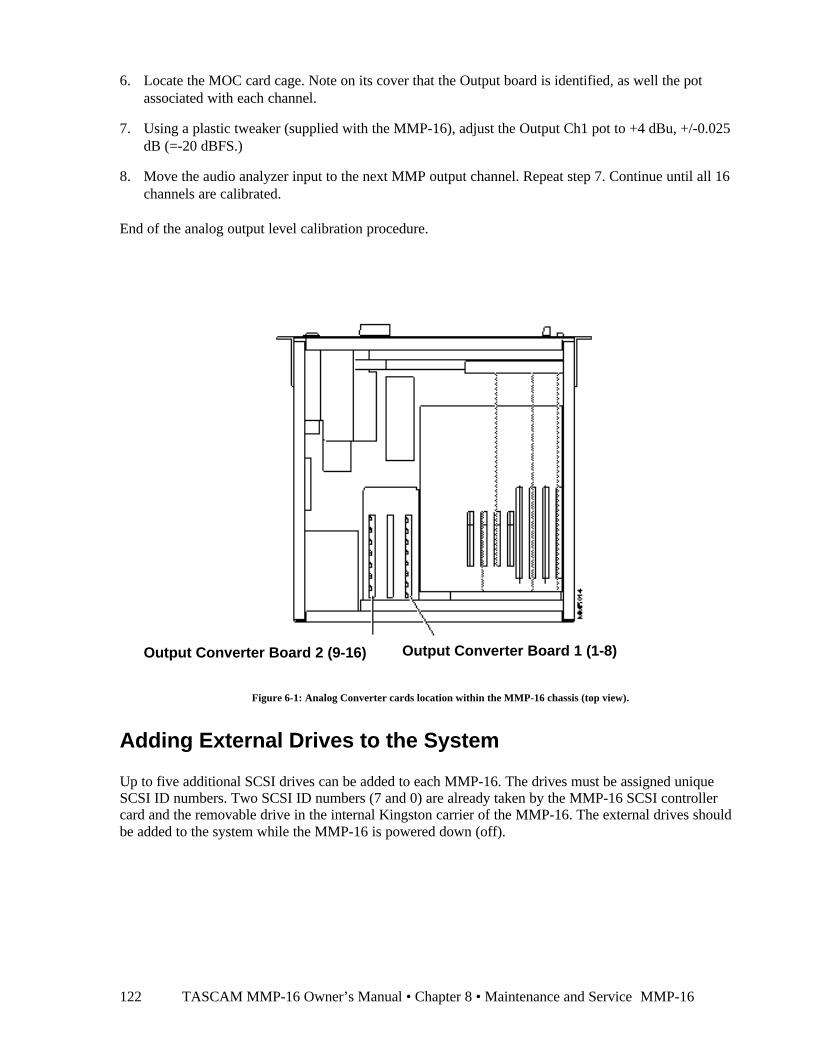
TASCAM MMP-16 Owner’s Manual • Chapter 8 • Maintenance and Service MMP-16122
6. Locate the MOC card cage. Note on its cover that the Output board is identified, as well the potassociated with each channel.
7. Using a plastic tweaker (supplied with the MMP-16), adjust the Output Ch1 pot to +4 dBu, +/-0.025dB (=-20 dBFS.)
8. Move the audio analyzer input to the next MMP output channel. Repeat step 7. Continue until all 16channels are calibrated.
End of the analog output level calibration procedure.
Figure 6-1: Analog Converter cards location within the MMP-16 chassis (top view).
Adding External Drives to the System
Up to five additional SCSI drives can be added to each MMP-16. The drives must be assigned uniqueSCSI ID numbers. Two SCSI ID numbers (7 and 0) are already taken by the MMP-16 SCSI controllercard and the removable drive in the internal Kingston carrier of the MMP-16. The external drives shouldbe added to the system while the MMP-16 is powered down (off).
Output Converter Board 2 (9-16) Output Converter Board 1 (1-8)
MMP-16 TASCAM MMP-16 Owner’s Manual • Chapter 8 • Maintenance and Service 123
Formatting Disks
The MMP-16 uses the WaveFrame disk format for recording, so disks from that system are compatiblewith the MMP-16, and disks can be formatted on the MMP-16 for use with the WaveFrame. There aretwo formatting options: Disk Initialize (menu 710), which is the typical formatting option; and Disk LowFormat (menu 711), which would be used on a brand new (unformatted at the factory) disk, a (software)damaged disk, or a disk that has been formatted for use on a non-Intel based system using anincompatible formatter.
When a new disk is added to the system, and you wish to initialize it, place the disk into the defaultsystem disk location. Go to Setup menu 710, and press STO to select Disk Format. A warning messagewill show in the display, asking if you wish to format the disk. Press STO to answer yes (or RCL toanswer no, returning you to Setup Menu 710). A further message will appear, asking if you are sure.Again, use STO for yes, RCL for no. If a password has been set, then the Enter Password: message willbe displayed and you will have to enter the password to continue with the format.
On disks that have been (software) damaged, or incompatibly formatted, repeat the above operation usingmenu 711 instead. Keep in mind that a low-level format can take from 20 minutes to an hour, duringwhich time the MMP-16 cannot be used for normal operation.
Using Removable Media
The MMP-16 currently supports two types of removable media: SCSI hard drives, and SCSI MOs(Magneto Optical) drives. The only type of SCSI hard drives that should be used are those specificallyrecommended by TASCAM, or drives and media that have been specified for use with high-demandapplications such as audio/video systems. These disks typically have faster access times (12 ms or fasteraverage seek time is required), larger storage capacities (2.4 GB or larger), and thermal compensation thatis only active when the drive is not being accessed. A list of approved removable media drives is given inAppendix B of this manual. Contact TASCAM for the most current list of recommended SCSI harddrives for the MMP-16. This list is also available on the TASCAM Web site at www.TASCAM.com.
For archiving and for transferring 4-track reels between the WaveFrame editor and the MMP-16, theTahiti 3 or similar optical drive may be used. The MMP-16 can format, backup to, or play back up to fourtracks off of 620 MB, 1.3 GB, or 2.6 GB MO media. The latest generation of LIM/DOW optical drives(such as the Nikon Beluga A/V drive) offer the best removable optical disk performance.
TASCAM MMP-16 Owner’s Manual • Chapter 9 • Technical Support124
Chapter 9 Technical SupportFor technical support on the MMP-16 product line contact:
TASCAM7733 Telegraph RoadMontebello, CA 90640Tel (213) 726-0303 Ext 617Fax (213) 727-7632E-mail: [email protected]
Technical assistance is only available to registered owners of MMP-16 products. Be sure to write downyour serial number before installation for future reference, as you will need it, along with the softwareversion you are currently running, when contacting technical support. You can write your serial numberhere:
MMP-16 serial #: ____________________________
Information on software updates, technical support, and TASCAM products is also available via theTASCAM World Wide Web site at:
http://www.tascam.com
MMP-16 System SoftwareThe MMP-16 operates using an industry-standard operating system and program files that run on aPentium microprocessor chip. The system software comes pre-installed onto the internal hard drive in theMMP-16. When the MMP-16 is turned on, all necessary software is loaded automatically. The version ofsoftware that is currently running can be displayed using Setup menu 990, which displays the currentrevision level of the software.
Software updates are supplied on one or more floppy disks. To install the software update, insert thefloppy disk (or Disk 1, if multiple disks are received) into the front panel floppy drive while the unit isoperating normally. Access Menu 995 (Load Software) and press STO. The system will ask “Are yousure?” Confirm the floppy is properly inserted and press STO again to confirm. If multiple disks aresupplied, the operator will be prompted via the display to remove Disk 1 and place Disk 2 into the drive.After the software update is installed, the system will display a message that the update is complete, andwill display a checksum number (written on the floppy update disk for reference) to verify that theinstallation has been successful. Remove the floppy disk and recycle the power to operate the unit withthe new software installed. All system floppy disks should be kept in a secure location in case they maybe needed in the future.
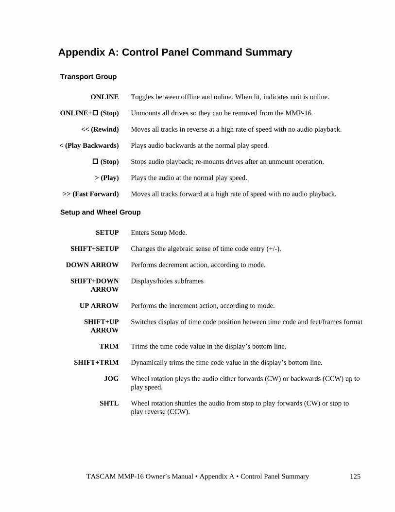
TASCAM MMP-16 Owner’s Manual • Appendix A • Control Panel Summary 125
Appendix A: Control Panel Command Summary
Transport Group
ONLINE Toggles between offline and online. When lit, indicates unit is online.
ONLINE+oo (Stop) Unmounts all drives so they can be removed from the MMP-16.
<< (Rewind) Moves all tracks in reverse at a high rate of speed with no audio playback.
< (Play Backwards) Plays audio backwards at the normal play speed.
oo (Stop) Stops audio playback; re-mounts drives after an unmount operation.
> (Play) Plays the audio at the normal play speed.
>> (Fast Forward) Moves all tracks forward at a high rate of speed with no audio playback.
Setup and Wheel Group
SETUP Enters Setup Mode.
SHIFT+SETUP Changes the algebraic sense of time code entry (+/-).
DOWN ARROW Performs decrement action, according to mode.
SHIFT+DOWNARROW
Displays/hides subframes
UP ARROW Performs the increment action, according to mode.
SHIFT+UPARROW
Switches display of time code position between time code and feet/frames format
TRIM Trims the time code value in the display’s bottom line.
SHIFT+TRIM Dynamically trims the time code value in the display’s bottom line.
JOG Wheel rotation plays the audio either forwards (CW) or backwards (CCW) up toplay speed.
SHTL Wheel rotation shuttles the audio from stop to play forwards (CW) or stop toplay reverse (CCW).

TASCAM MMP-16 Owner’s Manual • Appendix A • Control Panel Summary 126
Keypad keys
CLR Clears the time code in the bottom line of the display; cancels most operations
7 Enter digit, or selects 700 menus (in Setup)
SHIFT+7 Locate to “In point”
STO+7 Stores time code in bottom line of display into Memory register 7.
RCL+7 Recalls the time code in Memory register 7.
8 Enter digit, or selects 800 menus (in Setup)
SHIFT+8 Locate to “Head of tape” – follows SEL key selection in EDIT mode
STO+8 Stores time code in bottom line of display into Memory register 8.
RCL+8 Recalls the time code in Memory register 8.
9 Enter digit, or selects 900 menus (in Setup)
SHIFT+9 Locate to “Next Edit” point
STO+9 Stores time code in bottom line of display into Memory register 9.
RCL+9 Recalls the time code in Memory register 9.
SHIFT Modifies function of most keys
CAPT Captures the current time code and places it in the bottom line (active register).
SHIFT+CAPT
Time (Feet & Frames local zero) register
4 Enter digit, or selects 400 menus (in Setup)
SHIFT+4 Locate to “Out point”
STO+4 Stores time code in bottom line of display into Memory register 4.
RCL+4 Recalls the time code in Memory register 4.
5 Enter digit, or selects 500 menus (in Setup)
SHIFT+5 Locate to “Tail of tape” - follows SEL key selection in EDIT mode
STO+5 Stores time code in bottom line of display into Memory register 5.
RCL+5 Recalls the time code in Memory register 5.
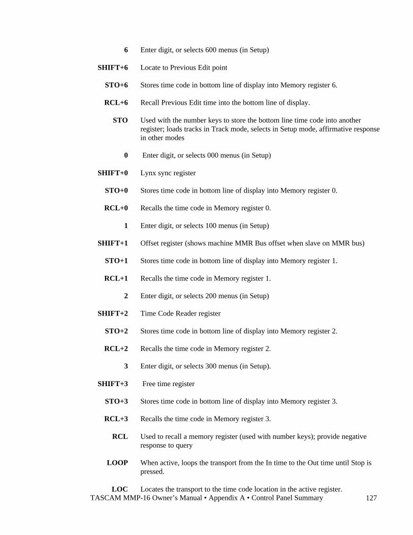
TASCAM MMP-16 Owner’s Manual • Appendix A • Control Panel Summary 127
6 Enter digit, or selects 600 menus (in Setup)
SHIFT+6 Locate to Previous Edit point
STO+6 Stores time code in bottom line of display into Memory register 6.
RCL+6 Recall Previous Edit time into the bottom line of display.
STO Used with the number keys to store the bottom line time code into anotherregister; loads tracks in Track mode, selects in Setup mode, affirmative responsein other modes
0 Enter digit, or selects 000 menus (in Setup)
SHIFT+0 Lynx sync register
STO+0 Stores time code in bottom line of display into Memory register 0.
RCL+0 Recalls the time code in Memory register 0.
1 Enter digit, or selects 100 menus (in Setup)
SHIFT+1 Offset register (shows machine MMR Bus offset when slave on MMR bus)
STO+1 Stores time code in bottom line of display into Memory register 1.
RCL+1 Recalls the time code in Memory register 1.
2 Enter digit, or selects 200 menus (in Setup)
SHIFT+2 Time Code Reader register
STO+2 Stores time code in bottom line of display into Memory register 2.
RCL+2 Recalls the time code in Memory register 2.
3 Enter digit, or selects 300 menus (in Setup).
SHIFT+3 Free time register
STO+3 Stores time code in bottom line of display into Memory register 3.
RCL+3 Recalls the time code in Memory register 3.
RCL Used to recall a memory register (used with number keys); provide negativeresponse to query
LOOP When active, loops the transport from the In time to the Out time until Stop ispressed.
LOC Locates the transport to the time code location in the active register.
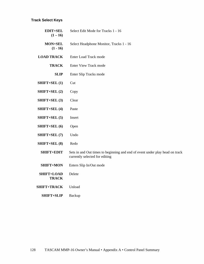
TASCAM MMP-16 Owner’s Manual • Appendix A • Control Panel Summary 128
Track Select Keys
EDIT+SEL(1 – 16)
Select Edit Mode for Tracks 1 - 16
MON+SEL(1 - 16)
Select Headphone Monitor, Tracks 1 - 16
LOAD TRACK Enter Load Track mode
TRACK Enter View Track mode
SLIP Enter Slip Tracks mode
SHIFT+SEL (1) Cut
SHIFT+SEL (2) Copy
SHIFT+SEL (3) Clear
SHIFT+SEL (4) Paste
SHIFT+SEL (5) Insert
SHIFT+SEL (6) Open
SHIFT+SEL (7) Undo
SHIFT+SEL (8) Redo
SHIFT+EDIT Sets in and Out times to beginning and end of event under play head on trackcurrently selected for editing
SHIFT+MON Enters Slip In/Out mode
SHIFT+LOADTRACK
Delete
SHIFT+TRACK Unload
SHIFT+SLIP Backup
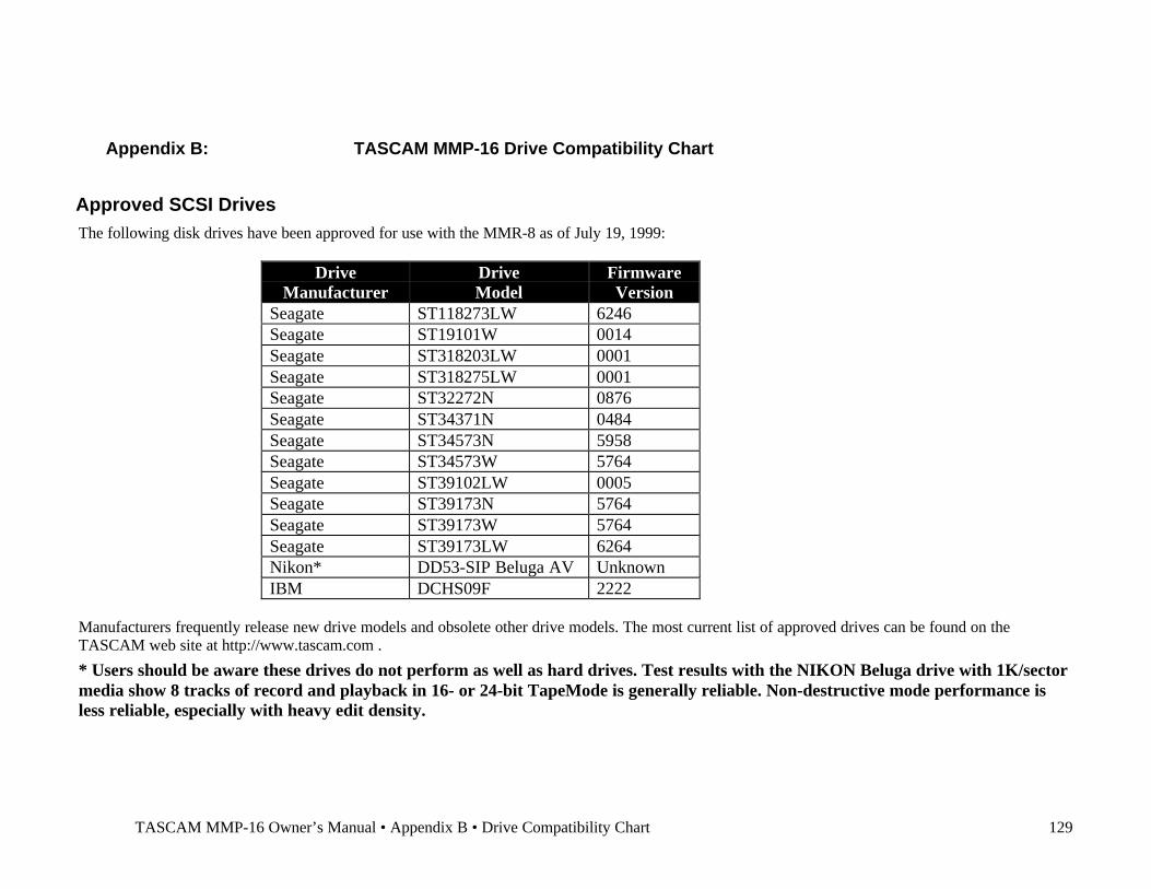
TASCAM MMP-16 Owner’s Manual • Appendix B • Drive Compatibility Chart 129
Appendix B: TASCAM MMP-16 Drive Compatibility Chart
Approved SCSI DrivesThe following disk drives have been approved for use with the MMR-8 as of July 19, 1999:
DriveManufacturer
DriveModel
FirmwareVersion
Seagate ST118273LW 6246Seagate ST19101W 0014Seagate ST318203LW 0001Seagate ST318275LW 0001Seagate ST32272N 0876Seagate ST34371N 0484Seagate ST34573N 5958Seagate ST34573W 5764Seagate ST39102LW 0005Seagate ST39173N 5764Seagate ST39173W 5764Seagate ST39173LW 6264Nikon* DD53-SIP Beluga AV UnknownIBM DCHS09F 2222
Manufacturers frequently release new drive models and obsolete other drive models. The most current list of approved drives can be found on theTASCAM web site at http://www.tascam.com .
* Users should be aware these drives do not perform as well as hard drives. Test results with the NIKON Beluga drive with 1K/sectormedia show 8 tracks of record and playback in 16- or 24-bit TapeMode is generally reliable. Non-destructive mode performance isless reliable, especially with heavy edit density.
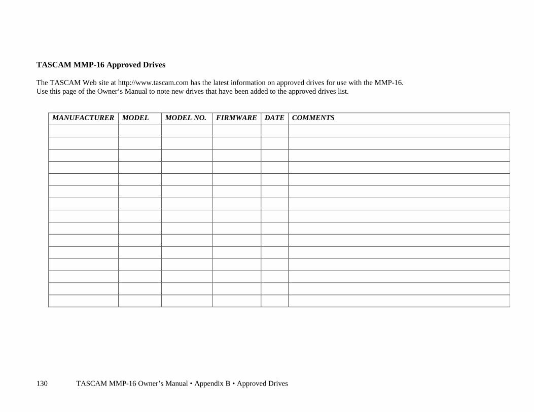
TASCAM MMP-16 Owner’s Manual • Appendix B • Approved Drives130
TASCAM MMP-16 Approved Drives
The TASCAM Web site at http://www.tascam.com has the latest information on approved drives for use with the MMP-16.Use this page of the Owner’s Manual to note new drives that have been added to the approved drives list.
MANUFACTURER MODEL MODEL NO. FIRMWARE DATE COMMENTS
TASCAM MMP-16 Owner’s Manual • Appendix C • WaveFrame Compatibility 131
Appendix C: WaveFrame CompatibilityThis section contains information on using the MMP-16 in the film post production environment thatheretofore has relied on a WaveFrame/StudioFrame system for playback on the mix stage.There are a number of considerations necessary to ensure compatibility between the MMP-16 andexisting WaveFrame/StudioFrame projects. WaveFrame/StudioFrame systems require at least one fixeddrive on the ‘A’ SCSI bus. On many StudioFrame systems, all drives are configured as “fixed” (i.e., non-removable). However, fixed drives in the StudioFrame system do not hold edit information, only the trackaudio. To store the edit information with the audio on the same drive requires that the drive be set up as a“removable” drive. The MMP-16, therefore, will work only with drives that have been configured by theworkstation as “removable”, since it relies on edit information being present on those drives. In addition,WaveFrame/StudioFrame systems place a maximum of four playable tracks of audio (perproject/reel/dub) on each disk volume.
The optimal configuration for a WaveFrame/StudioFrame system that is intended for use with the MMP-16 is as follows: The workstation would have the one required fixed drive on the ‘A’ SCSI bus, withenough additional drives for holding all tracks. The additional drives would all be configured as“removable” drives. Tracks 1-4 would be recorded onto drive 1A (the first removable drive), tracks 5-8would be recorded onto drive 1B (the second removable drive), and so on for any further groups of four.Although this is the best MMR/MMP-compatible configuration, earlier projects may have been createdunder other StudioFrame configurations using fixed drives. In these cases, a conversion procedure isnecessary in order to use the MMP-16 with the pre-recorded disk volumes. The following outlinedescribes the procedure for turning “fixed” StudioFrame drives into removable drives that can then bemoved to the MMP-16, with both track edits and audio information intact.
As an example, suppose we wished to make two drives “removable” that were attached as fixed drives tothe ‘A’ SCSI bus on the workstation. To make the fixed drives removable, you must first edit yourAutoexec.bat file to include this line somewhere in the file (for example, as the last line):SET NFREMOVEID=4
(To edit your Autoexec.bat file select File, Run and type SYSEDIT in the dialog box. Click on theAutoexec.bat window and type in the new command (SET NFREMOVEID=4) on a new line. Select File,Quit. Select Save to save the changes you made to the Autoexec.bat file.) Changing the Autoexec.bat filerequires rebooting for the change to take effect. You could also exit Windows, type the ‘set’ commandabove on the command line, and re-start Windows, if you do not wish to reboot. You would, however,have to do this every time the system was restarted.
To the WaveFrame/StudioFrame, this will signal that all SCSI drive addresses equal to or higher than four(4) are to be considered “removable” drives (lower numbers than 4 may be used, but be careful not toover-step any other lower addresses in use on the bus). Before re-starting your system, you mustphysically change the SCSI addresses of the two drives to SCSI id’s 4 and 5, or 5 and 6. The SCSI id’smust not be duplicated by any other drive on the SCSI bus.
StudioFrame Configuration Example A: 8-8-8 (8 track layout, tracks are in stereo pairs, on two fixeddrives). Sound was recorded to the F1 drive group.
Edit your Autoexec.bat file and (perhaps) change the SCSI address of your drives as described above.Restart the system, launch StudioFrame, and mount the now-removable drives. Disregard the “missingedits” message at startup (fixed disks do not have the edits stored on them, whereas removable drives do).Go into the Track Rack. Move all left channel tracks to the ‘1B’ drive and move all right channel tracks tothe ‘1A’ drive. Rebuild the database on both drives.
TASCAM MMP-16 Owner’s Manual • Appendix C • WaveFrame Compatibility132
StudioFrame Configuration Example B: 8-8-8 (8 track layout, tracks are in stereo pairs, two fixed drives).Sound was recorded as Tracks 1-4 to FA, Tracks 5-8 to FB.
Edit your Autoexec.bat file and change the SCSI address of your drives as described above. LaunchStudioFrame and mount the now-removable drives. Disregard the “missing edits” message at start up(fixed disks do not have the edits stored on them, whereas removable drives do).
Go into the Track Rack. Move tracks 1-4 to the ‘1A’ drive and move tracks 5-8 to the ‘1B’ drive. Rebuildthe database on both drives.
In each of the above examples, you will now have two removable drives with four tracks of audio (alongwith their edits) on each drive. If you have an external drive housing to hold a second drive, the twodrives, with four tracks each, can be used on a single MMP-16. If not, the MMP-16 can handle playing alleight tracks from one drive. To do this on the WaveFrame/StudioFrame, you must copy the tracks fromeither drive to the other drive using the Track Rack. This procedure will, as you know, require some timeto copy all the actual sound files.
If you moved all eight tracks to one drive and then need to bring the tracks back into StudioFrame fromthe MMP-16, you must mount the drives, go into the Track Rack, and swap the tracks onto the editor,making sure that you assign only four tracks per drive. Note: these swapped tracks will now be mono, andwill need to have their pans re-set (if they contained that information). If the audio was recorded in monoand had a pan value set, the pan value will be lost as well.
Note: For more detailed information on using the MMP-16 with theWaveFrame system, contact WaveFrame Company support in the UnitedStates at:
Advanced Systems Group (Oakland, CA)(510) 654-8300
Digital Difference (Burbank, CA)(818) 846-0589

TASCAM MMR-8/MMP-16 Owner’s Manual • Version 3.1 Update 133
Appendix D: MMP-16 Cable Information
Parallel Tracks and Parallel Transport Connector PinoutConnectors are 37-pin D male. I/O on connectors share same logical ground. Electrical characteristics are:
VCC
INPUT PIN
OUTPUT PIN
(+5V)
DARLINGTON OUTPUT STAGE OF ULN2803A
MAX RATINGS: 50V @ 500MA
TYPICAL INPUT
TYPICAL OUTPUT
10K
10K74HC14
1 2
2.7K
7.2K 3K
Tracks Tracks Transport
Switch Tally Switch Tally Switch Tally1. Record ON2. Record OFF
Locked 28.1. Trk 1 Input 21. 9. Trk 1 Rec 29. 9. Online 29.2. Trk 2 Input 22. 10. Trk 2 Rec 30. 10. Rewind 30.3. Trk 3 Input 23. 11. Trk 3 Rec 31. 11. Rev Play 31.4. Trk 4 Input 24. 12. Trk 4 Rec 32. 12. Stop 32.5. Trk 5 Input 25. 13. Trk 5 Rec 33. 13. Play 33.6. Trk 6 Input 26. 14. Trk 6 Rec 34. 14. FFwd 34.7. Trk 7 Input 27. 15. Trk 7 Rec 35. 15. Record 35.8. Trk 8 Input 28. 16. Trk 8 Rec 36. 16. Preview * 36.
Pins Common to Both Connectors19. +12VDC 20. GRD 37. GRD*When preview is grounded, all record functions will invoke rehearse.
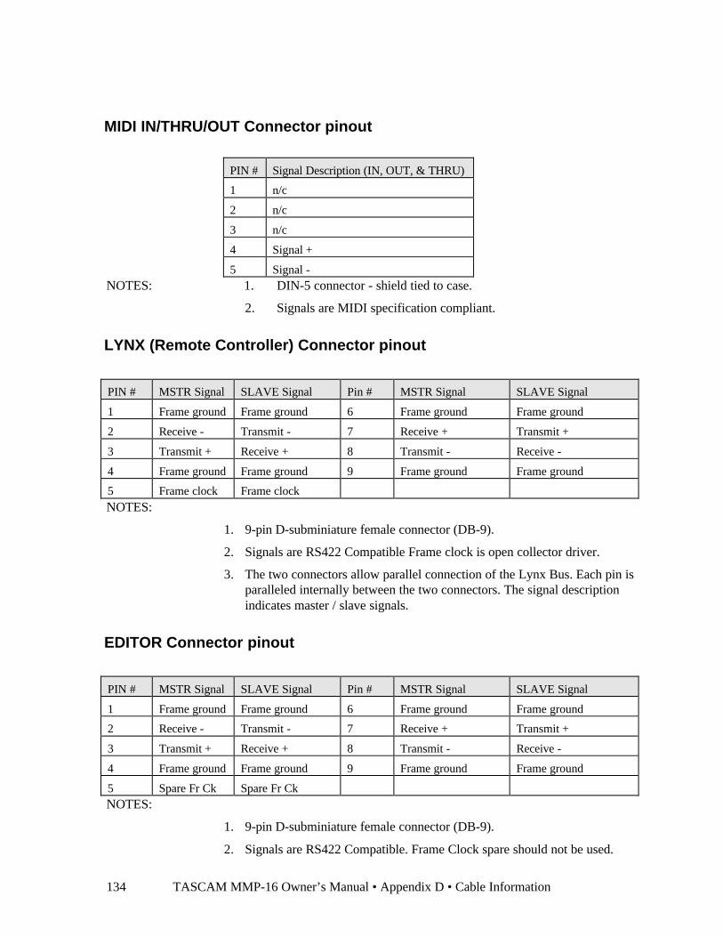
TASCAM MMP-16 Owner’s Manual • Appendix D • Cable Information134
MIDI IN/THRU/OUT Connector pinout
PIN # Signal Description (IN, OUT, & THRU)
1 n/c
2 n/c
3 n/c
4 Signal +
5 Signal -NOTES: 1. DIN-5 connector - shield tied to case.
2. Signals are MIDI specification compliant.
LYNX (Remote Controller) Connector pinout
PIN # MSTR Signal SLAVE Signal Pin # MSTR Signal SLAVE Signal
1 Frame ground Frame ground 6 Frame ground Frame ground
2 Receive - Transmit - 7 Receive + Transmit +
3 Transmit + Receive + 8 Transmit - Receive -
4 Frame ground Frame ground 9 Frame ground Frame ground
5 Frame clock Frame clockNOTES:
1. 9-pin D-subminiature female connector (DB-9).
2. Signals are RS422 Compatible Frame clock is open collector driver.
3. The two connectors allow parallel connection of the Lynx Bus. Each pin isparalleled internally between the two connectors. The signal descriptionindicates master / slave signals.
EDITOR Connector pinout
PIN # MSTR Signal SLAVE Signal Pin # MSTR Signal SLAVE Signal
1 Frame ground Frame ground 6 Frame ground Frame ground
2 Receive - Transmit - 7 Receive + Transmit +
3 Transmit + Receive + 8 Transmit - Receive -
4 Frame ground Frame ground 9 Frame ground Frame ground
5 Spare Fr Ck Spare Fr CkNOTES:
1. 9-pin D-subminiature female connector (DB-9).
2. Signals are RS422 Compatible. Frame Clock spare should not be used.
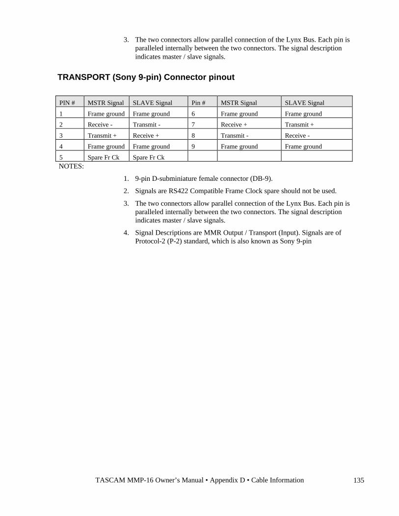
TASCAM MMP-16 Owner’s Manual • Appendix D • Cable Information 135
3. The two connectors allow parallel connection of the Lynx Bus. Each pin isparalleled internally between the two connectors. The signal descriptionindicates master / slave signals.
TRANSPORT (Sony 9-pin) Connector pinout
PIN # MSTR Signal SLAVE Signal Pin # MSTR Signal SLAVE Signal
1 Frame ground Frame ground 6 Frame ground Frame ground
2 Receive - Transmit - 7 Receive + Transmit +
3 Transmit + Receive + 8 Transmit - Receive -
4 Frame ground Frame ground 9 Frame ground Frame ground
5 Spare Fr Ck Spare Fr CkNOTES:
1. 9-pin D-subminiature female connector (DB-9).
2. Signals are RS422 Compatible Frame Clock spare should not be used.
3. The two connectors allow parallel connection of the Lynx Bus. Each pin isparalleled internally between the two connectors. The signal descriptionindicates master / slave signals.
4. Signal Descriptions are MMR Output / Transport (Input). Signals are ofProtocol-2 (P-2) standard, which is also known as Sony 9-pin
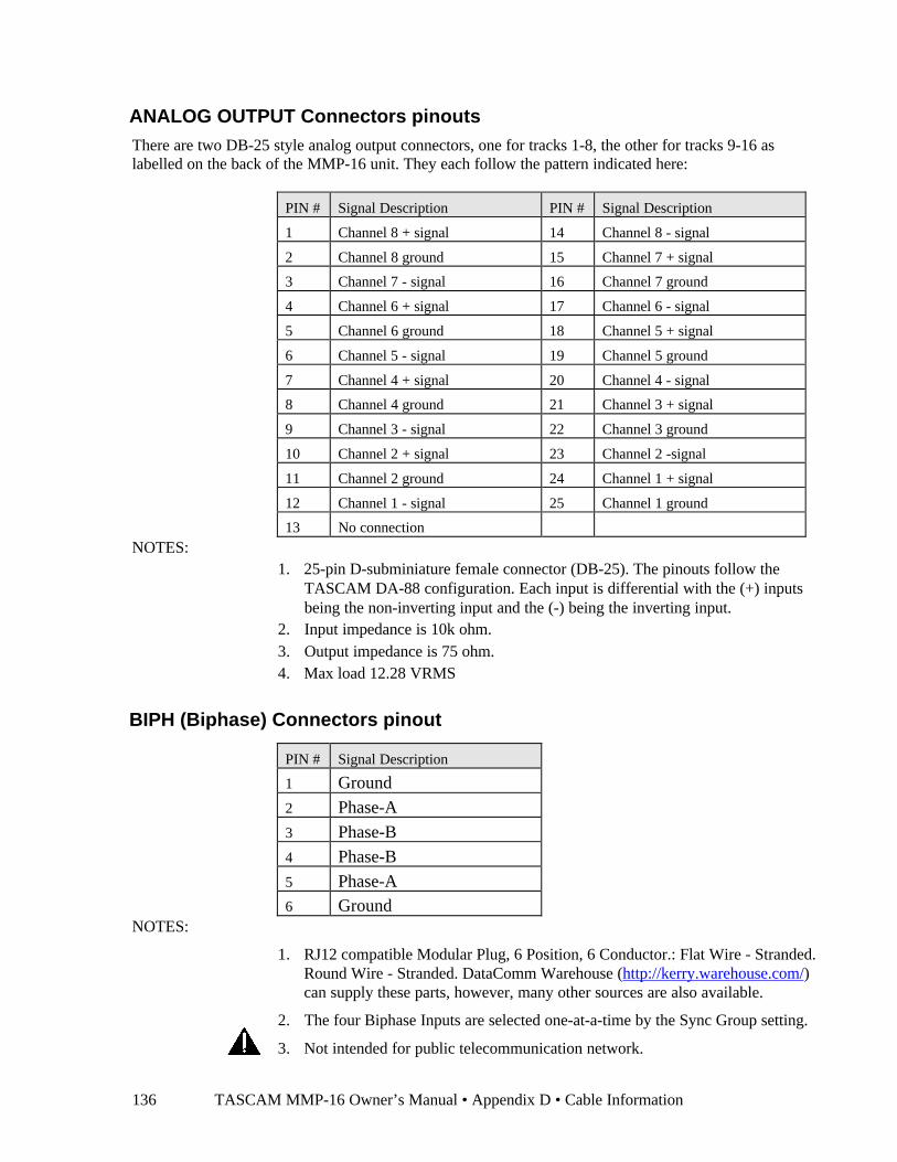
TASCAM MMP-16 Owner’s Manual • Appendix D • Cable Information136
ANALOG OUTPUT Connectors pinoutsThere are two DB-25 style analog output connectors, one for tracks 1-8, the other for tracks 9-16 aslabelled on the back of the MMP-16 unit. They each follow the pattern indicated here:
PIN # Signal Description PIN # Signal Description
1 Channel 8 + signal 14 Channel 8 - signal
2 Channel 8 ground 15 Channel 7 + signal
3 Channel 7 - signal 16 Channel 7 ground
4 Channel 6 + signal 17 Channel 6 - signal
5 Channel 6 ground 18 Channel 5 + signal
6 Channel 5 - signal 19 Channel 5 ground
7 Channel 4 + signal 20 Channel 4 - signal
8 Channel 4 ground 21 Channel 3 + signal
9 Channel 3 - signal 22 Channel 3 ground
10 Channel 2 + signal 23 Channel 2 -signal
11 Channel 2 ground 24 Channel 1 + signal
12 Channel 1 - signal 25 Channel 1 ground
13 No connectionNOTES:
1. 25-pin D-subminiature female connector (DB-25). The pinouts follow theTASCAM DA-88 configuration. Each input is differential with the (+) inputsbeing the non-inverting input and the (-) being the inverting input.
2. Input impedance is 10k ohm.3. Output impedance is 75 ohm.4. Max load 12.28 VRMS
BIPH (Biphase) Connectors pinout
PIN # Signal Description
1 Ground
2 Phase-A
3 Phase-B
4 Phase-B
5 Phase-A6 Ground
NOTES:
1. RJ12 compatible Modular Plug, 6 Position, 6 Conductor.: Flat Wire - Stranded.Round Wire - Stranded. DataComm Warehouse (http://kerry.warehouse.com/)can supply these parts, however, many other sources are also available.
2. The four Biphase Inputs are selected one-at-a-time by the Sync Group setting.
3. Not intended for public telecommunication network.

TASCAM MMP-16 Owner’s Manual • Appendix D • Cable Information 137
DO (AES/EBU Digital Audio Out 1-8) Connector pinout
PIN # Signal Description PIN # Signal Description
1 Digital Output 4 (ch 7&8) + signal 14 Digital Output 4 (ch 7&8) - signal
2 Digital Output 4 (ch 7&8) ground 15 Digital Output 3 (ch 5&6) + signal
3 Digital Output 3 (ch 5&6) - signal 16 Digital Output 3 (ch 5&6) ground
4 Digital Output 2 (ch 3&4) + signal 17 Digital Output 2 (ch 3&4) - signal
5 Digital Output 2 (ch 3&4) ground 18 Digital Output 1 (ch 1&2) + signal
6 Digital Output 1 (ch 1&2) - signal 19 Digital Output 1 (ch 1&2) ground
7 Digital Input 4 (ch 7&8) + signal 20 Digital Input 4 (ch 7&8) - signal
8 Digital Input 4 (ch 7&8) ground 21 Digital Input 3 (ch 5&6) + signal
9 Digital Input 3 (ch 5&6) - signal 22 Digital Input 3 (ch 5&6) ground
10 Digital Input 2 (ch 3&4) + signal 23 Digital Input 2 (ch 3&4) - signal
11 Digital Input 2 (ch 3&4) ground 24 Digital Input 1 (ch 1&2) + signal
12 Digital Input 1 (ch 1&2) - signal 25 Digital Input 1 (ch 1&2) ground
13 No connectionNOTES: 25-pin D-subminiature female connector (DB-25).
AO (AES/EBU Digital Audio Out 9-16) Connector pinout
PIN#
Signal Description PIN#
Signal Description
1 Digital Output 8 (ch 15&16) + signal 14 Digital Output 8 (ch 15&16) - signal
2 Digital Output 8 (ch 15&16) ground 15 Digital Output 7 (ch 13&14) + signal
3 Digital Output 7 (ch 13&14) - signal 16 Digital Output 7 (ch 13&14) ground
4 Digital Output 6 (ch 11&12) + signal 17 Digital Output 6 (ch 11&12) - signal
5 Digital Output 6 (ch 11&12) ground 18 Digital Output 5 (ch 9&10) + signal
6 Digital Output 5 (ch 9&10) - signal 19 Digital Output 5 (ch 9&10) ground
7 Digital Input 8 (ch 15&16) + signal 20 Digital Input 8 (ch 15&16) - signal
8 Digital Input 8 (ch 15&16) ground 21 Digital Input 7 (ch 13&14) + signal
9 Digital Input 7 (ch 13&14) - signal 22 Digital Input 7 (ch 13&14) ground
10 Digital Input 6 (ch 11&12) + signal 23 Digital Input 6 (ch 11&12) - signal
11 Digital Input 6 (ch 11&12) ground 24 Digital Input 5 (ch 9&10) + signal
12 Digital Input 5 (ch 9&10) - signal 25 Digital Input 5 (ch 9&10) ground
13 No connection
NOTES: 25-pin D-subminiature female connector (DB-25).
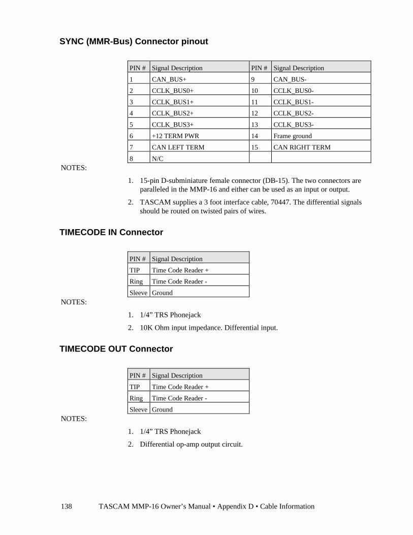
TASCAM MMP-16 Owner’s Manual • Appendix D • Cable Information138
SYNC (MMR-Bus) Connector pinout
PIN # Signal Description PIN # Signal Description
1 CAN_BUS+ 9 CAN_BUS-
2 CCLK_BUS0+ 10 CCLK_BUS0-
3 CCLK_BUS1+ 11 CCLK_BUS1-
4 CCLK_BUS2+ 12 CCLK_BUS2-
5 CCLK_BUS3+ 13 CCLK_BUS3-
6 +12 TERM PWR 14 Frame ground
7 CAN LEFT TERM 15 CAN RIGHT TERM
8 N/CNOTES:
1. 15-pin D-subminiature female connector (DB-15). The two connectors areparalleled in the MMP-16 and either can be used as an input or output.
2. TASCAM supplies a 3 foot interface cable, 70447. The differential signalsshould be routed on twisted pairs of wires.
TIMECODE IN Connector
PIN # Signal Description
TIP Time Code Reader +
Ring Time Code Reader -
Sleeve GroundNOTES:
1. 1/4” TRS Phonejack
2. 10K Ohm input impedance. Differential input.
TIMECODE OUT Connector
PIN # Signal Description
TIP Time Code Reader +
Ring Time Code Reader -
Sleeve GroundNOTES:
1. 1/4” TRS Phonejack
2. Differential op-amp output circuit.
TASCAM MMP-16 Owner’s Manual • Appendix D • Cable Information 139
WORD CLOCK IN Connector
NOTES:
1. BNC, 75 Ohm Terminated. TTL logic levels.
WORD CLOCK OUT Connector
NOTES:
1. BNC, 75 Ohm Drive Capability. TTL logic levels.
VIDEO IN/OUT Connector
NOTES:
1. BNC, Video is connected in parallel between connectors.
2. 1K Ohm input impedance. Supports Composite, Color Bars, Black Burst.Should be 75 ohm terminated if at end of cable.
SERIAL CONNECTORS
NOTES:
1. These connectors are for factory diagnostics only.
2. 9-pin D-subminiature female connector (DB-9), connected to COM1 on themotherboard.
3. 25-pin D-subminiature female Connector (DB-25), connected to COM2 on themotherboard.
SCSI Connector
NOTES:
1. SCSI-2 Compliant.
PRX Connector
NOTES:
1. 3.5 mm Stereo Phonejack.
2. Same audio signal as on Headphone Monitor, but audio on tip(left channel) only.
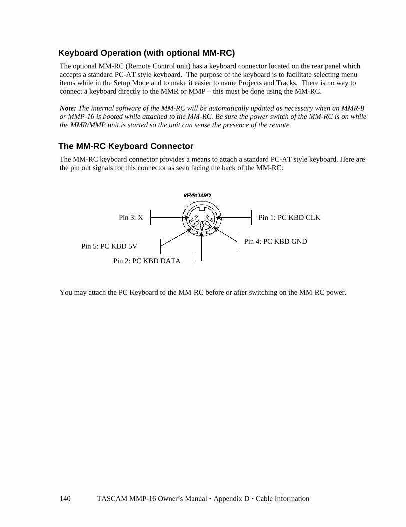
TASCAM MMP-16 Owner’s Manual • Appendix D • Cable Information140
Keyboard Operation (with optional MM-RC)The optional MM-RC (Remote Control unit) has a keyboard connector located on the rear panel whichaccepts a standard PC-AT style keyboard. The purpose of the keyboard is to facilitate selecting menuitems while in the Setup Mode and to make it easier to name Projects and Tracks. There is no way toconnect a keyboard directly to the MMR or MMP – this must be done using the MM-RC.
Note: The internal software of the MM-RC will be automatically updated as necessary when an MMR-8or MMP-16 is booted while attached to the MM-RC. Be sure the power switch of the MM-RC is on whilethe MMR/MMP unit is started so the unit can sense the presence of the remote.
The MM-RC Keyboard ConnectorThe MM-RC keyboard connector provides a means to attach a standard PC-AT style keyboard. Here arethe pin out signals for this connector as seen facing the back of the MM-RC:
You may attach the PC Keyboard to the MM-RC before or after switching on the MM-RC power.
Pin 1: PC KBD CLK
Pin 2: PC KBD DATA
Pin 4: PC KBD GND
Pin 3: X
Pin 5: PC KBD 5V
TASCAM MMP-16 Owner’s Manual • Appendix E • Glossary 141
Appendix E: MMP-16 GlossaryAbbreviations
and Terms Definitions
24 frames The standard film frame rate per second.
25 frames The standard PAL and SECAM video frame rate per second.
29.97 frames The standard NTSC video frame rate for color broadcasting per second.
30 frames The standard audio-only and black and white video frame rate per second.
AES/EBU Audio Engineering Society/European Broadcasting Union. The two mainorganizations that set the standards for audio production. Digital audioconnections are often referred to as AES/EBU since these organizationsstandardized the digital audio interconnection methods.
Autolocator An analog tape function to position the transport to previously markedlocations that is emulated in the MMP-16 using the LOC key and a register ormemory location to instantly locate the “play head.”
Biphase The two-pulse sync signal generated by a film transport that the MMP-16 usesto generate time code or feet & frames timing.
Bus Any signal that is daisy chained between multiple devices. In the case of theMMP-16, there are two main buses: the MMR bus and the Lynx Bus.
Calibrate Adjusting a signal to match a reference or standard. The MMP-16’s inputs canbe calibrated so that a +4 dBu signal will correctly drive the MMP-16, and theoutputs can be calibrated for a +4 dBu output from the MMP-16. In these casesthe calibration references are the level meters.
Capture During play or stop saves the current time code into the bottom line of the LCDdisplay for subsequent saving to a memory or position register.
Chase The process whereby one device controls another device to synchronize theirplayback. Chase implies there is both a synchronization signal as well as adevice control signal.
Clear A function to remove audio between the In and Out times on one or moretracks of audio.
Clip Indicates the maximum signal level has been exceeded going into the analog-digital converter. Typically this will cause severe distortion (popping, snapping,crackling sounds) in the output signal.
Control Mode The mode (menu 000) which sets how the MMP-16 is being controlled.
TASCAM MMP-16 Owner’s Manual • Appendix E • Glossary142
Abbreviationsand Terms Definitions
Control Track The VTR speed control signal recorded onto the tape. It typically also has timecode recorded in it.
DF Drop Frame. A type of time code that compensates for color video tape (whichruns at 29.97 frames per second) having 108 less frames per hour than blackand white video (which uses 30 frames per second). Since most videoproductions are in color, 108 frames must be “dropped” each hour from theaudio in order to keep audio and video in sync. 29.97 DF is the normal timecode used in the majority of video applications.
Dubber An audio transport that uses film sprockets as its timing device.
Edit The process of modifying the tracks in a project using the EDIT key and one ofthe edit functions (cut, copy, paste, clear, insert, open).
Error An LCD display that indicates a problem with the MMP-16 or with the lastoperator key entry.
Frame Each image on a film strip is a frame. In video, a frame consists of twointerlaced fields. In film there are 24 frames per second (fps). In video there are25 fps in the PAL and SECAM systems (European broadcasting) and 29.97 fpsin the NTSC system (USA and Japan). Older black and white video and audio-only applications use 30 fps.
Frame Reference The timing signal for each frame of video.
Groups There are four Sync Groups in the MMP-16. This allows multiple MMP-16s tobe shared between up to four film transports or video systems.
HH:MM:SS:FF SMPTE/EBU time code stated as Hours:Minutes:Seconds:Frames.
Head The start of a project.
Input Monitor Applies the MMP-16 track Input to the Output in lieu of the audio from thehard drive. Typically used to check Input levels before recording.
Interlock Refers to synchronizing film transports, audio dubbers and audio transports viathe biphase bus.
Jam Sync When discontinuous time code is found on a tape, jam sync will ignore the gapsto create continuous time code on another tape.
Jog Also called scrub, this function uses the Wheel to manually control the speed offorward and reverse play.
KCU Keyboard Control Unit. TimeLine’s external machine controller. Providesremote control for up to six machines (MMP-16s or tape machines).
LCD Liquid Crystal Display. The twenty character by two line display used on the
TASCAM MMP-16 Owner’s Manual • Appendix E • Glossary 143
Abbreviationsand Terms Definitions
MMP-16 to display time code, Setup Menus, or machine status.
LED Light Emitting Diode. Front panel indicators used to identify machine or key status.
Local When the MMP-16 is Off-line it is said to be in local mode.
Locate Jumps the MMP-16 (and any controlled machines) to a new time code locationusing the LOC key and one of the registers or memories.
Loop Plays the project between the In and Out time code points according to theLoop Mode setting selected in Setup Menu 110.
LTC Longitudinal Time Code. Time code that is recorded on audio tape or using oneof the audio tracks or the control track on videotape.
Lynx TimeLine’s machine controller interface bus that is compatible with the MMP-16, Lynx-2 Interface, the KCU, and Micro Lynx controllers.
Lynx Master The Lynx device that is the master for the Lynx bus. If one or more MMP-16sare tied to the Lynx bus only one can be the master on the Lynx bus.
Lynx Sync The Lynx bus frame clock.
Machine Any audio, video or film playback device.
MachineControl
Remote control commands for positional control and operational control of adevice. In the case of the MMP-16, machine control commands can come fromthe MIDI input, the Lynx or MMR buses, the Editor input or the parallel remoteinput.
Master The device that is in positional control of one or more slave devices.
MIDI Musical Instrument Digital Interface. A serial data connection originally usedto communicate key and voice parameters between music synthesizers. TheMMP-16 will respond to MMC (MIDI Machine Commands) but will ignoreany other signals transmitted on the MIDI bus.
MMR Bus An asynchronous bus that ties multiple MMP-16s together to relay motioncontrol commands and timing references from the master machine to the slavemachines. The MMR bus supports up to four Sync Groups with their owntiming references and motion control commands.
MMR Master The MMP-16 that is in control of a particular Sync Group on the MMR bus.
Mixdown The process of bringing together the multiple tracks of dialogue, FX, Foley,and music to create a finished soundtrack for a film or video production.

TASCAM MMP-16 Owner’s Manual • Appendix E • Glossary144
Abbreviationsand Terms Definitions
Monitor The process of selecting one or more tracks to listen to in the headphones orrear panel studio monitor output.
Motion Controls The “transport” keys on the MMP-16.
MTC MIDI Time Code. Time code that is transmitted as part of a MIDI signal.Because there is not enough room for the complete time code to be sent at once,MTC counts in two frame increments.
Multitrack A tape or solid state device that can record and/or playback more than one trackof audio at a time.
NDF Non-Drop Frame. A type of time code that uses full frames for timing. It isused in audio-only applications and with black and white video.
NTSC National TV Standards Committee. The television and video format used in theUSA and Japan. The basic frame rate is 30 fps for monochrome and 29.97 fpsfor color transmissions and recording.
Offset The amount of difference between the program time code and an event. Tracksand entire machines can be offset. Offsets are sometimes added to correct forincorrect time code numbers on a tape or to compensate for timing delaysbetween machines.
Operating State There are eight operating states of the MMP-16, Normal, Setup, Load Track,View Track, Slip Track, Backup,Verify, and Error. These are distinguished bythe nature of the information displayed in the LCD window and by the keysthat are available while in each state.
PAL Phase Alternating Line. The main European broadcasting standard that uses a25 fps rate.
Phase Lock The process where a machine is locked to reference signal (or to anothermachine’s reference signal) so that its reference signal can be matched in phaseby controlling the speed of the machine compared to the other machine or to aspeed reference signal.
RAM Random Access Memory. To convert audio from analog into digital, or viceversa, a RAM buffer is required to allow the continuous analog audio to beconverted into “chunks” of digital data and the chunks of data from the harddrive to be converted back into continuous analog audio.
Rate How many ticks per second of some clock or other counter. There are variousrates used in the MMP-16 include fps (frames per second), ppf (pulse perframe, biphase), word clock (samples per second)
Reference The master clock. The MMP-16 uses two reference signals: a sample referencefor the audio and a frame reference to keep the audio timed correctly to thevideo or film frame.
TASCAM MMP-16 Owner’s Manual • Appendix E • Glossary 145
Abbreviationsand Terms Definitions
Register A memory that holds a time code position or other number. There are 11dedicated registers (to hold such numbers as the Head, Tail, In and Out points,etc.) plus 10 memory registers (0 -9) in the MMP-16.
Reshape The process of regenerating incoming time code so that the time code output isclean and free of noise or other signal distortions.
Resolving The process of regulating the playback speed of a machine through phaselocking a recorded signal on the tape to a fixed reference signal.
Safe No recording can take place since all record enables are locked out.
SampleReference
The reference for the digital audio sample clock in the MMP-16. It can comefrom a digital input, from the word clock input, or from the frame reference.
SCSI Small Computer System Interface. The bus that connects external removabledrives to the MMP-16.
Setup Menus The method through which operating parameters are changed and set in theMMP-16. To bring up the Setup Menus on the LCD display press the Setupkey.
Shuttle Manual control over the machine transport from stop to play to fast forwardand from stop to reverse play to rewind through using the Wheel.
Slip The process of adding slight timing offsets to individual tracks.
SMPTE Society of Motion Picture & Television Engineers. The organization thatdeveloped and approved the video time code that is often referred to as SMPTEor SMPTE/EBU code.
Sync Group Each MMP-16 can be placed into one of four Sync Groups, or groups ofmachines that can be controlled together. The Sync Group also selects thebiphase input that is being used.
Sync Word Part of the SMPTE/EBU time code, the sync word indicates the end of the timecode word. It can also be used to determine the direction the transport ismoving as well as for phase locking.
TC Time Code. The 80 bit biphase-encoded code that marks the time on a video oraudio tape in hours:minutes:seconds:frames:subframes. It also identifies thetype of code being used (DF or NDF). It can be recorded longitudinally alongthe edge of a tape or recorded within the vertical interval on a video tape. Timecode can also be encoded onto film, although in most applications the timecode will be generated from the film transport biphase signal.
TASCAM MMP-16 Owner’s Manual • Appendix E • Glossary146
TC Generator Time Code Generator. A device to create the 80 bit time code signal forrecording onto a video or audio tape. The MMP-16 contains a built-in generatorwhich is always sending out TC when the MMP-16 is playing.
TC Reader Time Code Reader. The circuit in the MMP-16 that reads incoming time codefrom the time code inputs. Typically used to slave the MMP-16 to another timecode generator’s output.
Tail The end of the track’s audio.
Track Can refer to one of the audio channels in the MMP-16, but typically it refers tothe edited audio for one track of audio on the reel.
Track Select The process of selecting which tracks an action affects through using the SELkey for that track.
Transport A generic reference to any audio, video, or film device that mechanically“moves tape” or electronically plays audio or video.
Trim The process of adjusting the time code using the Wheel.
Unmount The process of releasing the removable hard drive from the MMP-16 so that itcan be removed.
User Settings When any MMP-16 Setup parameters have been changed, the new settings canbe saved in a User Settings File (menu 900). Ten User Settings are available.
Video Sync Also known as house sync, it is generated by an extremely stable video sourceand consists of black burst, sync bars, or composite video. It’s used as a timingreference to synchronize video devices throughout a video facility.
Virtual Tracks Audio tracks that are “stacked” on top of one another so that alternate takes canbe kept at hand. Only the track on top will actually play back.
VITC Vertical Interval Time Code. SMPTE/EBU time code that is recorded withinthe video signal on a VTR. VITC can be read during fast searches and evenwhen the video machine is paused since the rotating VTR heads are alwaysreading the video portion of the tape. VITC is not supported in the MM Series.
VSO Variable Speed Oscillator. Indicates that the audio is not being played back at a“standard” playback speed, but is rather playing back at an off-speed for aneffect or to compensate for incorrect timing between devices.
Word Clock The digital audio clocking signal (44.1 or 48 kHz most commonly used) used tosynchronize audio devices.
Wheel The rotary encoder on the MMP-16 front panel that can be used to trim, jog,and shuttle audio, in addition to being used to scroll through the Setup Menusand menu choices.
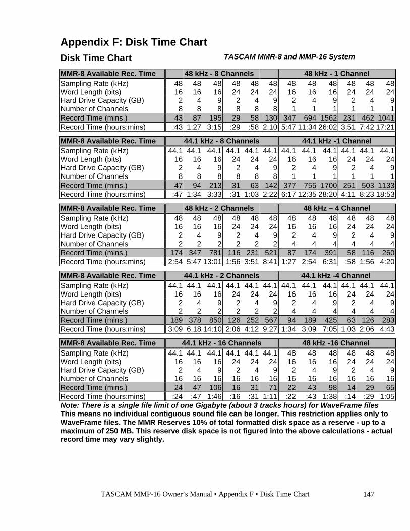
TASCAM MMP-16 Owner’s Manual • Appendix F • Disk Time Chart 147
Appendix F: Disk Time ChartDisk Time Chart TASCAM MMR-8 and MMP-16 System
MMR-8 Available Rec. Time 48 kHz - 8 Channels 48 kHz - 1 ChannelSampling Rate (kHz) 48 48 48 48 48 48 48 48 48 48 48 48Word Length (bits) 16 16 16 24 24 24 16 16 16 24 24 24Hard Drive Capacity (GB) 2 4 9 2 4 9 2 4 9 2 4 9Number of Channels 8 8 8 8 8 8 1 1 1 1 1 1Record Time (mins.) 43 87 195 29 58 130 347 694 1562 231 462 1041Record Time (hours:mins) :43 1:27 3:15 :29 :58 2:10 5:47 11:34 26:02 3:51 7:42 17:21
MMR-8 Available Rec. Time 44.1 kHz - 8 Channels 44.1 kHz -1 ChannelSampling Rate (kHz) 44.1 44.1 44.1 44.1 44.1 44.1 44.1 44.1 44.1 44.1 44.1 44.1Word Length (bits) 16 16 16 24 24 24 16 16 16 24 24 24Hard Drive Capacity (GB) 2 4 9 2 4 9 2 4 9 2 4 9Number of Channels 8 8 8 8 8 8 1 1 1 1 1 1Record Time (mins.) 47 94 213 31 63 142 377 755 1700 251 503 1133Record Time (hours:mins) :47 1:34 3:33 :31 1:03 2:22 6:17 12:35 28:20 4:11 8:23 18:53
MMR-8 Available Rec. Time 48 kHz - 2 Channels 48 kHz – 4 ChannelSampling Rate (kHz) 48 48 48 48 48 48 48 48 48 48 48 48Word Length (bits) 16 16 16 24 24 24 16 16 16 24 24 24Hard Drive Capacity (GB) 2 4 9 2 4 9 2 4 9 2 4 9Number of Channels 2 2 2 2 2 2 4 4 4 4 4 4Record Time (mins.) 174 347 781 116 231 521 87 174 391 58 116 260Record Time (hours:mins) 2:54 5:47 13:01 1:56 3:51 8:41 1:27 2:54 6:31 :58 1:56 4:20
MMR-8 Available Rec. Time 44.1 kHz - 2 Channels 44.1 kHz -4 ChannelSampling Rate (kHz) 44.1 44.1 44.1 44.1 44.1 44.1 44.1 44.1 44.1 44.1 44.1 44.1Word Length (bits) 16 16 16 24 24 24 16 16 16 24 24 24Hard Drive Capacity (GB) 2 4 9 2 4 9 2 4 9 2 4 9Number of Channels 2 2 2 2 2 2 4 4 4 4 4 4Record Time (mins.) 189 378 850 126 252 567 94 189 425 63 126 283Record Time (hours:mins) 3:09 6:18 14:10 2:06 4:12 9:27 1:34 3:09 7:05 1:03 2:06 4:43
MMR-8 Available Rec. Time 44.1 kHz - 16 Channels 48 kHz -16 ChannelSampling Rate (kHz) 44.1 44.1 44.1 44.1 44.1 44.1 48 48 48 48 48 48Word Length (bits) 16 16 16 24 24 24 16 16 16 24 24 24Hard Drive Capacity (GB) 2 4 9 2 4 9 2 4 9 2 4 9Number of Channels 16 16 16 16 16 16 16 16 16 16 16 16Record Time (mins.) 24 47 106 16 31 71 22 43 98 14 29 65Record Time (hours:mins) :24 :47 1:46 :16 :31 1:11 :22 :43 1:38 :14 :29 1:05Note: There is a single file limit of one Gigabyte (about 3 tracks hours) for WaveFrame filesThis means no individual contiguous sound file can be longer. This restriction applies only toWaveFrame files. The MMR Reserves 10% of total formatted disk space as a reserve - up to amaximum of 250 MB. This reserve disk space is not figured into the above calculations - actualrecord time may vary slightly.
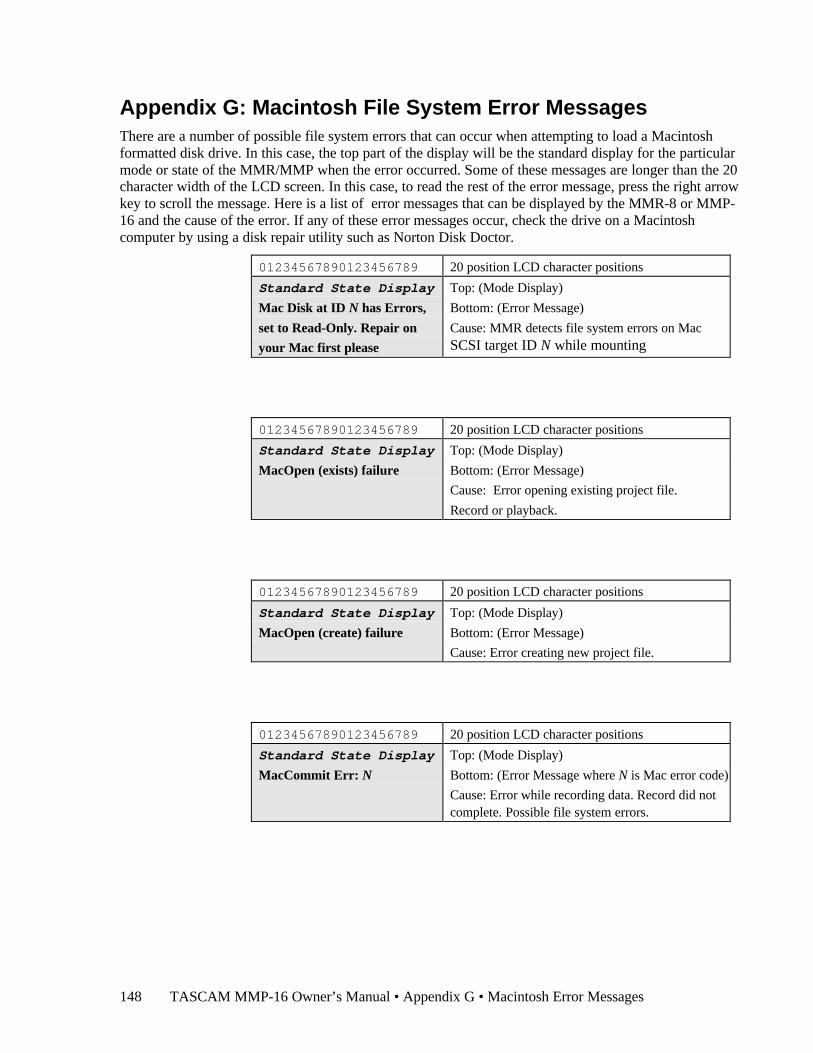
TASCAM MMP-16 Owner’s Manual • Appendix G • Macintosh Error Messages148
Appendix G: Macintosh File System Error MessagesThere are a number of possible file system errors that can occur when attempting to load a Macintoshformatted disk drive. In this case, the top part of the display will be the standard display for the particularmode or state of the MMR/MMP when the error occurred. Some of these messages are longer than the 20character width of the LCD screen. In this case, to read the rest of the error message, press the right arrowkey to scroll the message. Here is a list of error messages that can be displayed by the MMR-8 or MMP-16 and the cause of the error. If any of these error messages occur, check the drive on a Macintoshcomputer by using a disk repair utility such as Norton Disk Doctor.
01234567890123456789 20 position LCD character positions
Standard State Display Top: (Mode Display)
Mac Disk at ID N has Errors,
set to Read-Only. Repair on
your Mac first please
Bottom: (Error Message)
Cause: MMR detects file system errors on MacSCSI target ID N while mounting
01234567890123456789 20 position LCD character positions
Standard State Display Top: (Mode Display)
MacOpen (exists) failure Bottom: (Error Message)
Cause: Error opening existing project file.
Record or playback.
01234567890123456789 20 position LCD character positions
Standard State Display Top: (Mode Display)
MacOpen (create) failure Bottom: (Error Message)
Cause: Error creating new project file.
01234567890123456789 20 position LCD character positions
Standard State Display Top: (Mode Display)
MacCommit Err: N Bottom: (Error Message where N is Mac error code)
Cause: Error while recording data. Record did notcomplete. Possible file system errors.
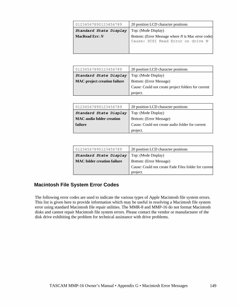
TASCAM MMP-16 Owner’s Manual • Appendix G • Macintosh Error Messages 149
01234567890123456789 20 position LCD character positions
Standard State Display Top: (Mode Display)
MacRead Err: N Bottom: (Error Message where N is Mac error code)Cause: SCSI Read Error on drive N
01234567890123456789 20 position LCD character positions
Standard State Display Top: (Mode Display)
MAC project creation failure Bottom: (Error Message)
Cause: Could not create project folders for current
project.
01234567890123456789 20 position LCD character positions
Standard State Display Top: (Mode Display)
MAC audio folder creation
failure
Bottom: (Error Message)
Cause: Could not create audio folder for current
project.
01234567890123456789 20 position LCD character positions
Standard State Display Top: (Mode Display)
MAC folder creation failure Bottom: (Error Message)
Cause: Could not create Fade Files folder for currentproject.
Macintosh File System Error Codes
The following error codes are used to indicate the various types of Apple Macintosh file system errors.This list is given here to provide information which may be useful in resolving a Macintosh file systemerror using standard Macintosh file repair utilities. The MMR-8 and MMP-16 do not format Macintoshdisks and cannot repair Macintosh file system errors. Please contact the vendor or manufacturer of thedisk drive exhibiting the problem for technical assistance with drive problems.

TASCAM MMP-16 Owner’s Manual • Appendix G • Macintosh Error Messages150
Volinfo errors
Error Name Error # Comment .
READVIFAILED -1 Failed to read volume info block WRITEVIFAILED -2 Failed to write volume info block READVIOUTOFMEM -3 WRITEVIOUTOFMEM -4 NOTHFSDISK -5
Readwrite errors
Error Name Error # Comment .
READSECTFAILED -10 Couldn't read *any* sectors WRITESECTFAILED -11 Couldn't write *any* sectors INITREADWRITEFAILED -12 Couldn't init read/write pkg. INVALIDSTATEREC -13 Trying to read/write a mountrecord which
has not had initreadwrite sucessfully run onit.
CLOSEREADWRITEFAILED -14 Could not shutdown read/write WRITESECTUNBUFFAILED -15 could not perform unbuffered write or
sync mount record
Volume Bitmap errors
Error Name Error # Comment .
READVBMCANTREAD -30 Can't read volume bit map READVBMOUTOFMEM -31 ran out of mem reading vol bmap WRITEVBMCANTWRITE -32 can't write volume bit map CHKVBMAPBADVIBINFO -33 Volume bitmap is inconsistent FREECSBADRANGE -34 Trying to contiguously allocate
a bad range ALLOCSOUTOFMEM -35 Contiguous allocation ran out of
memory
The following result from allocation failing and not being able to rollback the changes that have already been done
ALLOCSCANTDEALLOC1 -36 Deallocation failed at stage 1 ALLOCSCANTDEALLOC2 -37 Deallocation failed at stage 2 ALLOCSCANTDEALLOC3 -38 Deallocation failed at stage 3 ALLOCSOUTOFBOUNDS -39 Internal error happened – the allocator
returned more space than asked for

TASCAM MMP-16 Owner’s Manual • Appendix G • Macintosh Error Messages 151
Mac ReadWrite Errors
Error Name Error # Comment . MACREADEXTNOTFOUND -80 Could not find an extent GENEDLISTOUTOFMEM -81 Generate Extent List ran out of memory GENEDLISTINTERNALERR -82 Gen extent list had internal err GENEDLISTBLOCKNOTFOUND -83 Gen extent list could not a logical block
of the file MACREADOUTOFMEM -84 read ran out of memory CANTREADALLOCBLOCK -85 readsects failed to read a block MACREADOUTOFBOUNDS -86 Internal problem -macread discovered that
it read more blocks than were requested MACREADNOTENOUGHEDS -87 there weren't enough extents on the edlist
to complete the read MACWRITECANTGROWFILE -88 macwrite couldn't expand the file MACWRITEOUTOFMEM -89 macwrite ran out of memory MACWRITECANTREAD -90 macwrite couldn't read a block MACWRITECANTWRITE -91 macwrite couldn't write a block FILEISNOTWRITABLE -92 you're trying to write a file that was not
opened writeable FILEISNOTREADABLE -93 you're trying to read a file that was not
opened readable BADWHENCE -94 macseek was passed a bad whence MACWRITEOUTOFBOUNDS -95 CANTWRITEALLOCBLOCK -96
BTREE ERRORS
Error Name Error # Comment . BT_MANYEXTENTS -100 Btree has more than 3 extents BT_NODENOTFOUND -101 Looking for an inexistent node BT_BADCATALOGTYPE -102 BT_UNIMPLEMENTED -103 BT_BADKEY -104 BT_FOUNDLESS -105 The Btree is empty BT_NOTFOUND -106 The key was not found BT_BADTREE -107 A data structure error BT_BIGTREE -108 Don't want to extend the tree BT_BADRECORD -109 BT_BUG1 -110 BT_NOTALLOC -111 BT_BADNODE -112 BT_BUG2 -113 BT_TOOHIGH -114 The Btree is higher than BT_MAX_DEPTH BT_WRITE_NODE_FAILED -115 BT_BADHEADER -116 BT_CHECK -200 CheckBTree
200 --> 300 reserved for BT_CHECK
Catalog Support Errors
Error Name Error # Comment . OPENROOTNOSUCHFILE -450 Opening the root failed–there is a serious
problem with the FS

TASCAM MMP-16 Owner’s Manual • Appendix G • Macintosh Error Messages152
PCROUTOFMEMORY -451 The path resolver ran out of memory PCRBADPATHELEMENT -452 path has a bad element in it PCRNOSUCHPATHELEMENT -453 path has a nonexisting element PCRGOTFILENOTDIR -454 path resolver encountered a file when it
was expecting a dir PCRCWDNOTDIR -455 relative path search with a non directory
current working dir was attempted PCRUNEXPECTEDTYPE -456 path resolver encountered a thread record CLOSEFAILED -470 Unable to close file MACDIROUTOFMEM -473 mdirentries ran out of memory MACDIRTRYDECLOWESTFN -474 Internal error in m/macdirentries MACCREATEFILEOUTOFMEM -475 create file ran out of mem MACCREATEFILECANTDEALLOC -476 create file failed and then rollback failed MACCREATEFILENOSPACE -477 no available space to create file MACCREATEFOLDOUTOFMEM -478 create folder ran out of mem MACCREATEFOLDCANTDEALLOC -479 create folder failed and then NOSUCHFOLDER -480 function could not find folder MACDELFILEFAILED -490 macdel couldn't delete a file MACDELNOSUCHFOLDER -491 macdelfolder on nonexistent fold MACDELNOTAFOLDER -492 macdelfolder on nonfolder MACDELBADFOLDER -493 Folder without thread record MACDELCANTDELTHREADREC -494 Couldn't delete thread record MACDELCANTDELFOLDER -495 Couldn't delete folder MACDELNOSUCHFILE -496 macdelfile on nonexisting file MACDELNOTAFILE -497 macdelfile on non-file MACDELNOTHREADREC -498 macdelfolder couldn't find thread thread
record CANTCREATEINNONDIR -499 try to create a file in someplace that is
not a folder
Error Name Error # Comment . BADFILEORFOLDERNAME -500 Illegal file or folder name MACDELFOLDERNOTEMPTY -501 try to del nonempty folder NAMETOOLONG -502 bad name - too long MOVENOTFOLDER -503 movefolder on nonfolder MOVENOTHDREC -504 movefolder couldn't find thread record MOVECANTMODIFYTHDREC -505 movefolder couldn't modify thread record MOVECANTDELFOLDREC -506 movefolder couldn't del old folder record MOVECANTPUTNEWFOLDREC -507 movefolder couldn't put new folder record MOVECANTDELFILEREC -509 movefile couldn't del file rec MOVECANTPUTNEWFILEREC -510 movefile couldn't put new file rec MOVENOTFILE -511 movefile on non file MOVEWOULDOVERWRITE -512 move would overwrite something MOVENOTFILEORFOLDER -513 move on nonfile/nonfolder TOOMANYOPENFILES -514 open failed because catrectable is full MOVEPARENTINTOCHILD -515 Try to move parent folder into child folder
failed MOVEINTERNALERROR -516 Move encountered internal error MOVEFAILDURINGFAIL -517 Move failed, then failed during rollback –
bad CANTFINDTHDREC -518 Couldn't find a thread record MGROWDOESNTTRUNC -519 Trying to truncate using mgrowfile MGROWNOTENOUGHSPACE -520 mgrowfile could not find enough space to
grow to desired size MGROWCANTFINDLASTER -521 mgrow could not find last extent record of
the file MGROWCANTWRITELASTER -522 mgrow couldn't write the last extent record
of a file

TASCAM MMP-16 Owner’s Manual • Appendix G • Macintosh Error Messages 153
MGROWGREWTOWRONGSIZE -523 mgrowfile internal error file grew toincorrect size
FILEISGONE -524 This means that you are trying to read,write, or close an open file which someonedeleted/moved out from under you.
CANTUPDATEDIR -525 Could not update directory times andvalence
BADPATH -526 was given a bad path CANONLYOPENFILES -527 Try to macopen a non-file TRUNCTONONZEROSIZE -528 Tried to truncate to nonzero size CANONLYTRUNCFILES -529 Tried to truncate a nonfile CANTOVERWRITEDIR -530 Tried to overwrite a folder CREATEFOLDWOULDOVERWRITE -531 Creating the folder would overwrite an
existing item MACREADCANTREAD -550 macreadblocks failed in mread FILEISNOTOPEN -551 Tried to close nonopen file INVALIDMFILE -552 The MFILE you passed is garbage CANTSETNONFILEFINDERINFO -553 We only do files right now... CANTGETNONFILEFINDERINFO -554 We only do files right now... CANNOTCREATEFILE -555 Only create files withabsolute path FILEISINUSE -556 Cannot delete open files
Partition Errors
Error Name Error # Comment . PARTOUTOFMEM -600 Ran out of memory PARTCANTREADSECTZERO -601 Couldn't read the device map UNRECOGNIZEDTYPE -603 Doesn't have valid device map PARTCANTREADPARTMAPSECT -604 Couldn't read partition map BADPARTITION -605 Asked to mount a non MAC HFS partition
Error Name Error # Comment .
NOTMACHFSPART -606 It looked like a MAC HFS part, but afterreading vib, we don't think so
ALLOCSBITMAPFULL -607 No more room left on disk FOLDERNAMETOOLONG -608 safeguard in create/delete folder routines INVALIDOFFSET -609 offset not madgetsector too big. NOTSECTORALLIGNED -610 offset to macgetsector not sector aligned SECTOR_SIZE_MISMATCH -611 Sector size gotten from device does not
match sector size in partition table
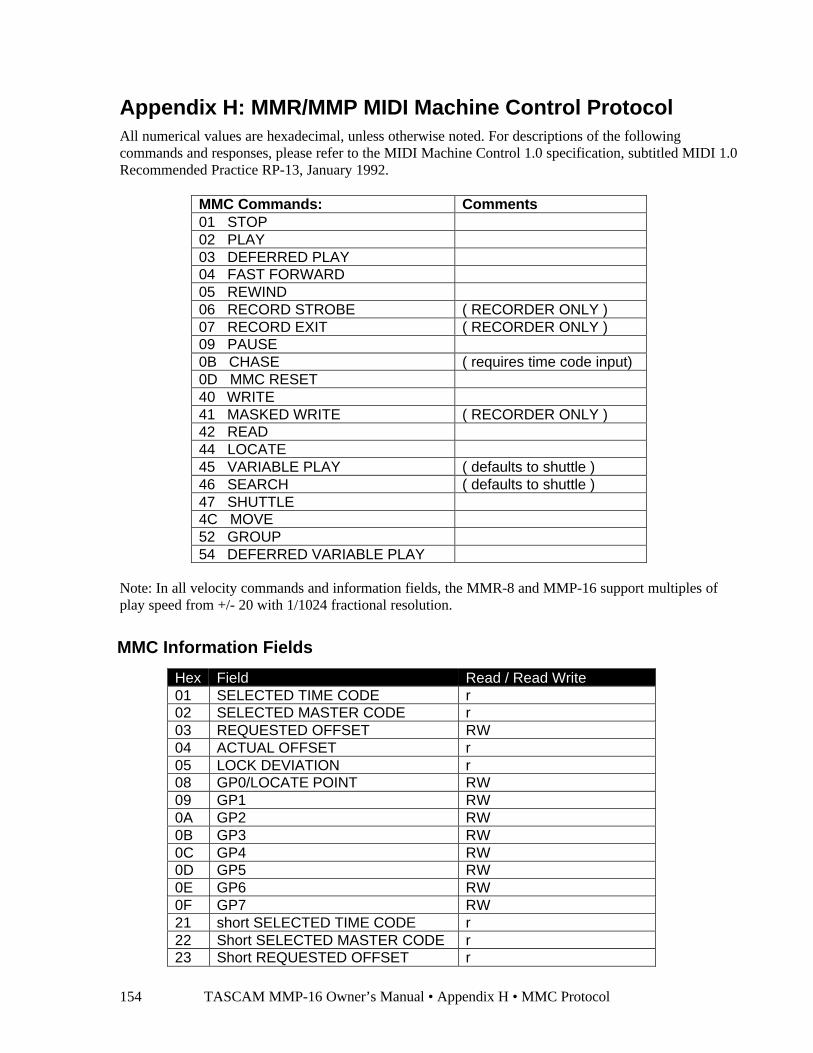
TASCAM MMP-16 Owner’s Manual • Appendix H • MMC Protocol154
Appendix H: MMR/MMP MIDI Machine Control ProtocolAll numerical values are hexadecimal, unless otherwise noted. For descriptions of the followingcommands and responses, please refer to the MIDI Machine Control 1.0 specification, subtitled MIDI 1.0Recommended Practice RP-13, January 1992.
MMC Commands: Comments01 STOP02 PLAY03 DEFERRED PLAY04 FAST FORWARD05 REWIND06 RECORD STROBE ( RECORDER ONLY )07 RECORD EXIT ( RECORDER ONLY )09 PAUSE0B CHASE ( requires time code input)0D MMC RESET40 WRITE41 MASKED WRITE ( RECORDER ONLY )42 READ44 LOCATE45 VARIABLE PLAY ( defaults to shuttle )46 SEARCH ( defaults to shuttle )47 SHUTTLE4C MOVE52 GROUP54 DEFERRED VARIABLE PLAY
Note: In all velocity commands and information fields, the MMR-8 and MMP-16 support multiples ofplay speed from +/- 20 with 1/1024 fractional resolution.
MMC Information Fields
Hex Field Read / Read Write01 SELECTED TIME CODE r02 SELECTED MASTER CODE r03 REQUESTED OFFSET RW04 ACTUAL OFFSET r05 LOCK DEVIATION r08 GP0/LOCATE POINT RW09 GP1 RW0A GP2 RW0B GP3 RW0C GP4 RW0D GP5 RW0E GP6 RW0F GP7 RW21 short SELECTED TIME CODE r22 Short SELECTED MASTER CODE r23 Short REQUESTED OFFSET r
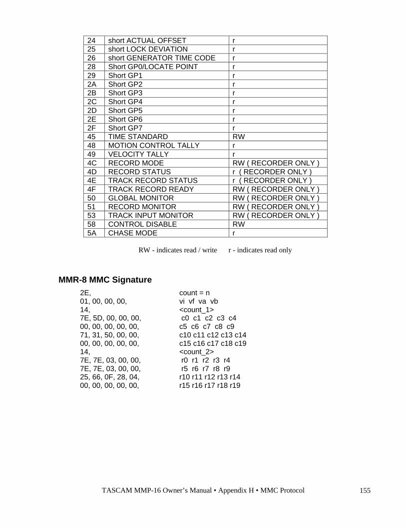
TASCAM MMP-16 Owner’s Manual • Appendix H • MMC Protocol 155
24 short ACTUAL OFFSET r25 short LOCK DEVIATION r26 short GENERATOR TIME CODE r28 Short GP0/LOCATE POINT r29 Short GP1 r2A Short GP2 r2B Short GP3 r2C Short GP4 r2D Short GP5 r2E Short GP6 r2F Short GP7 r45 TIME STANDARD RW48 MOTION CONTROL TALLY r49 VELOCITY TALLY r4C RECORD MODE RW ( RECORDER ONLY )4D RECORD STATUS r ( RECORDER ONLY )4E TRACK RECORD STATUS r ( RECORDER ONLY )4F TRACK RECORD READY RW ( RECORDER ONLY )50 GLOBAL MONITOR RW ( RECORDER ONLY )51 RECORD MONITOR RW ( RECORDER ONLY )53 TRACK INPUT MONITOR RW ( RECORDER ONLY )58 CONTROL DISABLE RW5A CHASE MODE r
RW - indicates read / write r - indicates read only
MMR-8 MMC Signature 2E, count = n 01, 00, 00, 00, vi vf va vb 14, <count_1> 7E, 5D, 00, 00, 00, c0 c1 c2 c3 c4 00, 00, 00, 00, 00, c5 c6 c7 c8 c9 71, 31, 50, 00, 00, c10 c11 c12 c13 c14 00, 00, 00, 00, 00, c15 c16 c17 c18 c19 14, <count_2> 7E, 7E, 03, 00, 00, r0 r1 r2 r3 r4 7E, 7E, 03, 00, 00, r5 r6 r7 r8 r9 25, 66, 0F, 28, 04, r10 r11 r12 r13 r14 00, 00, 00, 00, 00, r15 r16 r17 r18 r19
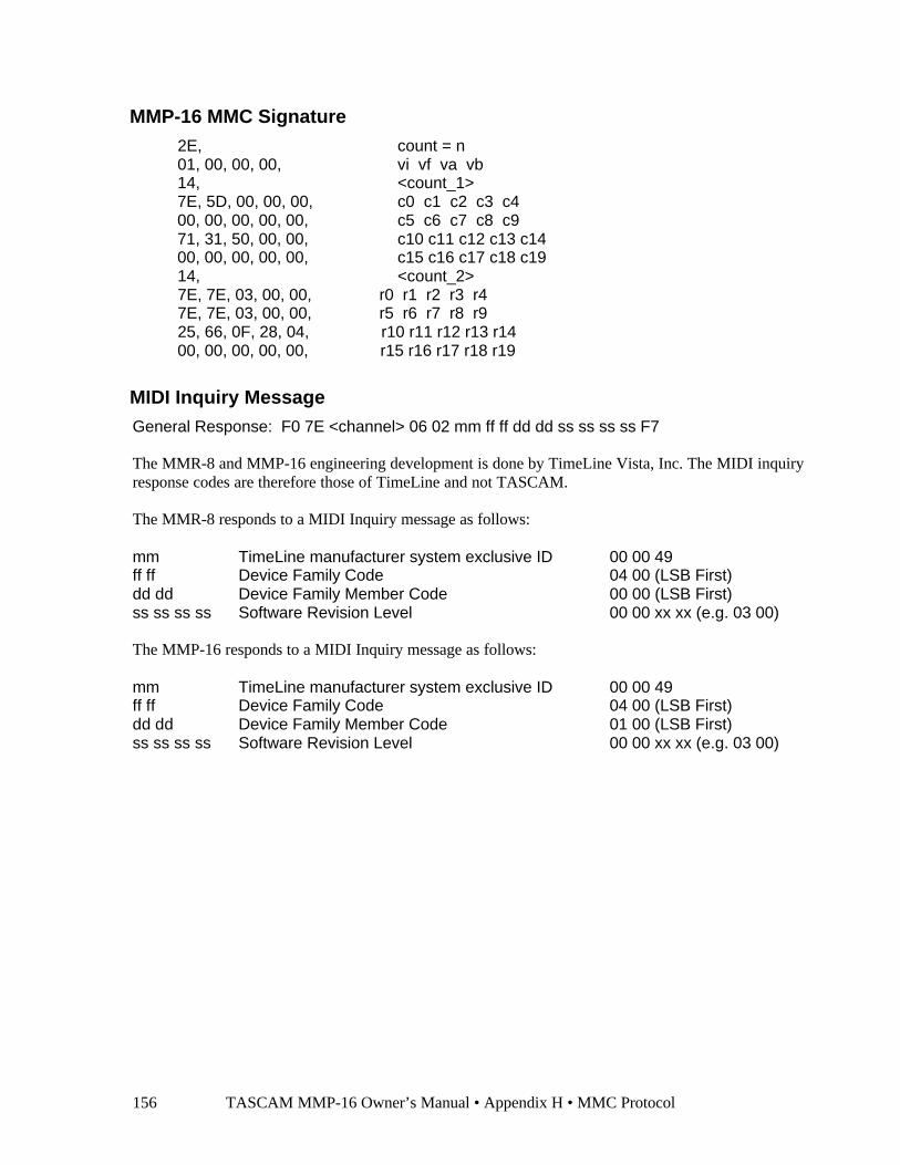
TASCAM MMP-16 Owner’s Manual • Appendix H • MMC Protocol156
MMP-16 MMC Signature 2E, count = n 01, 00, 00, 00, vi vf va vb 14, <count_1> 7E, 5D, 00, 00, 00, c0 c1 c2 c3 c4 00, 00, 00, 00, 00, c5 c6 c7 c8 c9 71, 31, 50, 00, 00, c10 c11 c12 c13 c14 00, 00, 00, 00, 00, c15 c16 c17 c18 c19 14, <count_2> 7E, 7E, 03, 00, 00, r0 r1 r2 r3 r4 7E, 7E, 03, 00, 00, r5 r6 r7 r8 r9 25, 66, 0F, 28, 04, r10 r11 r12 r13 r14 00, 00, 00, 00, 00, r15 r16 r17 r18 r19
MIDI Inquiry MessageGeneral Response: F0 7E <channel> 06 02 mm ff ff dd dd ss ss ss ss F7
The MMR-8 and MMP-16 engineering development is done by TimeLine Vista, Inc. The MIDI inquiryresponse codes are therefore those of TimeLine and not TASCAM.
The MMR-8 responds to a MIDI Inquiry message as follows:
mm TimeLine manufacturer system exclusive ID 00 00 49ff ff Device Family Code 04 00 (LSB First)dd dd Device Family Member Code 00 00 (LSB First)ss ss ss ss Software Revision Level 00 00 xx xx (e.g. 03 00)
The MMP-16 responds to a MIDI Inquiry message as follows:
mm TimeLine manufacturer system exclusive ID 00 00 49ff ff Device Family Code 04 00 (LSB First)dd dd Device Family Member Code 01 00 (LSB First)ss ss ss ss Software Revision Level 00 00 xx xx (e.g. 03 00)
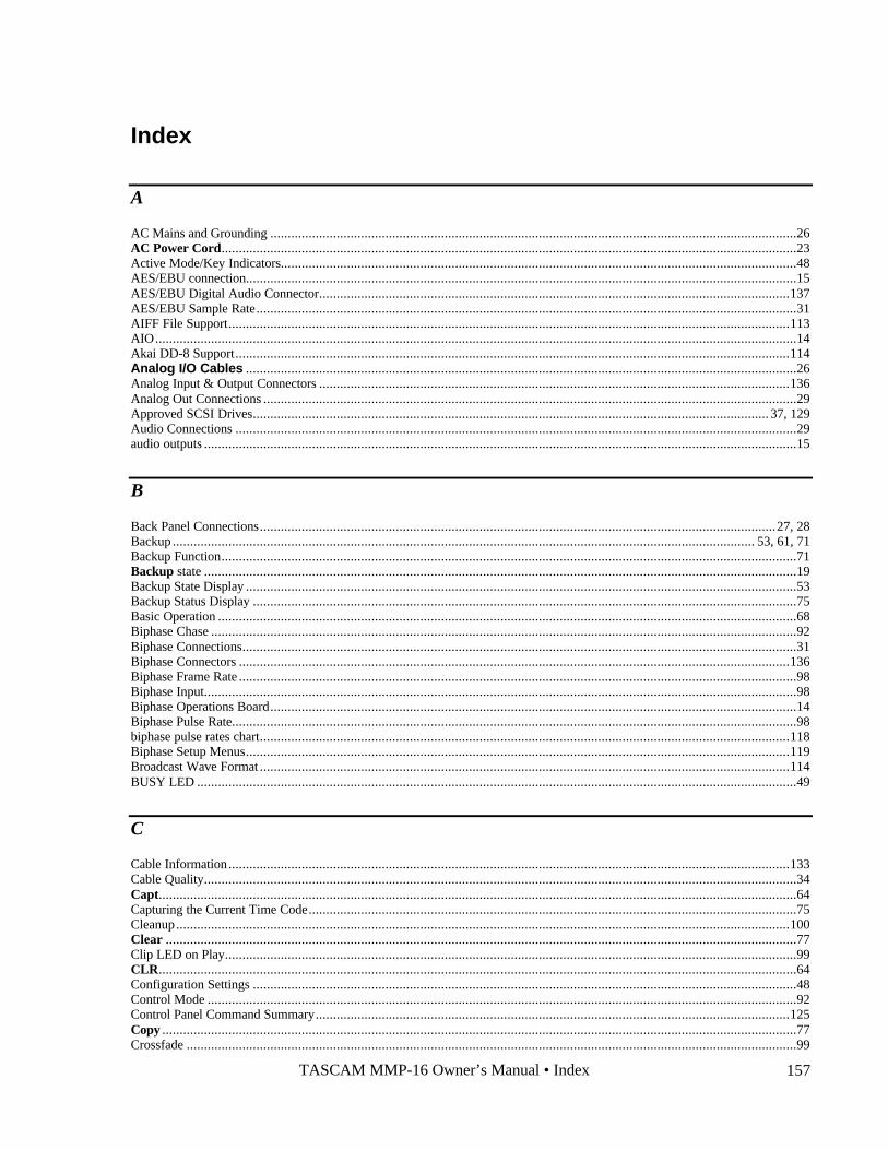
TASCAM MMP-16 Owner’s Manual • Index 157
Index
A
AC Mains and Grounding .......................................................................................................................................................26AC Power Cord.....................................................................................................................................................................23Active Mode/Key Indicators....................................................................................................................................................48AES/EBU connection..............................................................................................................................................................15AES/EBU Digital Audio Connector.......................................................................................................................................137AES/EBU Sample Rate...........................................................................................................................................................31AIFF File Support.................................................................................................................................................................113AIO........................................................................................................................................................................................14Akai DD-8 Support...............................................................................................................................................................114Analog I/O Cables ..............................................................................................................................................................26Analog Input & Output Connectors .......................................................................................................................................136Analog Out Connections .........................................................................................................................................................29Approved SCSI Drives.................................................................................................................................................... 37, 129Audio Connections .................................................................................................................................................................29audio outputs ..........................................................................................................................................................................15
B
Back Panel Connections....................................................................................................................................................27, 28Backup ....................................................................................................................................................................... 53, 61, 71Backup Function.....................................................................................................................................................................71Backup state ..........................................................................................................................................................................19Backup State Display ..............................................................................................................................................................53Backup Status Display ............................................................................................................................................................75Basic Operation ......................................................................................................................................................................68Biphase Chase ........................................................................................................................................................................92Biphase Connections...............................................................................................................................................................31Biphase Connectors ..............................................................................................................................................................136Biphase Frame Rate ................................................................................................................................................................98Biphase Input..........................................................................................................................................................................98Biphase Operations Board.......................................................................................................................................................14Biphase Pulse Rate..................................................................................................................................................................98biphase pulse rates chart........................................................................................................................................................118Biphase Setup Menus............................................................................................................................................................119Broadcast Wave Format ........................................................................................................................................................114BUSY LED ............................................................................................................................................................................49
C
Cable Information.................................................................................................................................................................133Cable Quality..........................................................................................................................................................................34Capt.......................................................................................................................................................................................64Capturing the Current Time Code............................................................................................................................................75Cleanup................................................................................................................................................................................100Clear .....................................................................................................................................................................................77Clip LED on Play....................................................................................................................................................................99CLR.......................................................................................................................................................................................64Configuration Settings ............................................................................................................................................................48Control Mode .........................................................................................................................................................................92Control Panel Command Summary........................................................................................................................................125Copy ......................................................................................................................................................................................77Crossfade ...............................................................................................................................................................................99
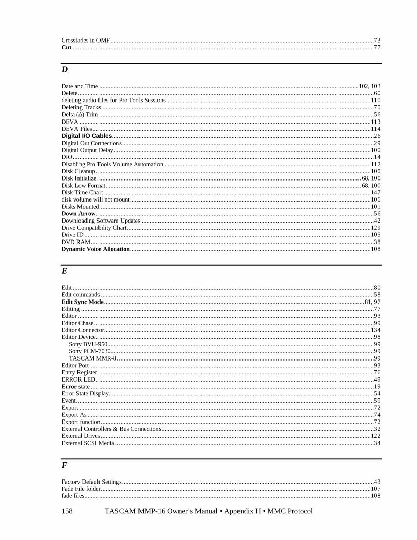
TASCAM MMP-16 Owner’s Manual • Appendix H • MMC Protocol158
Crossfades in OMF .................................................................................................................................................................73Cut ........................................................................................................................................................................................77
D
Date and Time .............................................................................................................................................................. 102, 103Delete.....................................................................................................................................................................................60deleting audio files for Pro Tools Sessions.............................................................................................................................110Deleting Tracks ......................................................................................................................................................................70Delta (∆) Trim ........................................................................................................................................................................56DEVA ..................................................................................................................................................................................113DEVA Files..........................................................................................................................................................................114Digital I/O Cables................................................................................................................................................................26Digital Out Connections..........................................................................................................................................................29Digital Output Delay.............................................................................................................................................................100DIO........................................................................................................................................................................................14Disabling Pro Tools Volume Automation ..............................................................................................................................112Disk Cleanup........................................................................................................................................................................100Disk Initialize ................................................................................................................................................................. 68, 100Disk Low Format............................................................................................................................................................ 68, 100Disk Time Chart ...................................................................................................................................................................147disk volume will not mount ...................................................................................................................................................106Disks Mounted .....................................................................................................................................................................101Down Arrow..........................................................................................................................................................................56Downloading Software Updates ..............................................................................................................................................42Drive Compatibility Chart.....................................................................................................................................................129Drive ID ...............................................................................................................................................................................105DVD RAM.............................................................................................................................................................................38Dynamic Voice Allocation...................................................................................................................................................108
E
Edit ........................................................................................................................................................................................80Edit commands .......................................................................................................................................................................58Edit Sync Mode...............................................................................................................................................................81, 97Editing ...................................................................................................................................................................................77Editor .....................................................................................................................................................................................93Editor Chase...........................................................................................................................................................................99Editor Connector...................................................................................................................................................................134Editor Device..........................................................................................................................................................................98
Sony BVU-950...................................................................................................................................................................99Sony PCM-7030.................................................................................................................................................................99TASCAM MMR-8 .............................................................................................................................................................99
Editor Port..............................................................................................................................................................................93Entry Register.........................................................................................................................................................................76ERROR LED..........................................................................................................................................................................49Error state .............................................................................................................................................................................19Error State Display..................................................................................................................................................................54Event......................................................................................................................................................................................59Export ....................................................................................................................................................................................72Export As ...............................................................................................................................................................................74Export function.......................................................................................................................................................................72External Controllers & Bus Connections..................................................................................................................................32External Drives.....................................................................................................................................................................122External SCSI Media ..............................................................................................................................................................34
F
Factory Default Settings..........................................................................................................................................................43Fade File folder.....................................................................................................................................................................107fade files...............................................................................................................................................................................108
TASCAM MMP-16 Owner’s Manual • Index 159
Fairlight MFX3 support ........................................................................................................................................................116Fast Forward Key .................................................................................................................................................................55file system errors ..................................................................................................................................................................106Film Post Production.............................................................................................................................................................118Format..................................................................................................................................................................................100Format Chart ........................................................................................................................................................................116Formatting Disks ..................................................................................................................................................................123formatting Macintosh disks ...................................................................................................................................................105Formatting Macintosh Disks..................................................................................................................................................105frame rate/sample rate support...............................................................................................................................................109Frame Reference.....................................................................................................................................................................94
Automatic ..........................................................................................................................................................................94Video.................................................................................................................................................................................94
Free........................................................................................................................................................................................63Front Panel .............................................................................................................................................................................15Front Panel Controls ...............................................................................................................................................................55Front Panel Controls and Indicators .........................................................................................................................................48
G
Glossary ...............................................................................................................................................................................141
H
Hardware Overview................................................................................................................................................................14Head.......................................................................................................................................................................................64Headphone Jack......................................................................................................................................................................82Headphone Volume ................................................................................................................................................................82Hybrid Protocol on Serial Port.................................................................................................................................................94
I
Ident Assigned..................................................................................................................................................................85, 96Ident Request....................................................................................................................................................................85, 96In Point...................................................................................................................................................................................63Insert .....................................................................................................................................................................................78Installation..............................................................................................................................................................................23Installing Multiple MMR Units ...............................................................................................................................................25Intel Pentium™ ......................................................................................................................................................................14INTERLOCK LED .................................................................................................................................................................49Introduction ............................................................................................................................................................................13IP
Gateway...........................................................................................................................................................................102NetMask ..........................................................................................................................................................................102
IP Address Format ................................................................................................................................................................102IP Address Rules ..................................................................................................................................................................103
J
Jaz drive .................................................................................................................................................................................38Jog .........................................................................................................................................................................................57
K
Keyboard Operation................................................................................................................................................................39Keyboard Operation with MM-RC ........................................................................................................................................140Keypad Group ........................................................................................................................................................................62
TASCAM MMP-16 Owner’s Manual • Appendix H • MMC Protocol160
Keys.......................................................................................................................................................................................44Keys & Definitions .................................................................................................................................................................44Kingston Carrier .....................................................................................................................................................................14Kingston Frame Configuration ................................................................................................................................................35Kingston removable drive carrier.............................................................................................................................................23
L
LCD .......................................................................................................................................................................................15LED Indicators .......................................................................................................................................................................48LED peak meters ....................................................................................................................................................................15LIM/DOW..............................................................................................................................................................................38LIMDOW...............................................................................................................................................................................38Liquid Crystal Display (LCD) .................................................................................................................................................50Load Track ...........................................................................................................................................................................59Load Track state....................................................................................................................................................................18Load Track State Display ........................................................................................................................................................52Loading a Project, Session, or Composition .............................................................................................................................69Loading and Mounting Drives.................................................................................................................................................68Loading Individual Tracks ......................................................................................................................................................69LOC (Locate) ........................................................................................................................................................................67Local/Bus ...............................................................................................................................................................................92LOCK LED ............................................................................................................................................................................49Loop ......................................................................................................................................................................................66Loop Mode.............................................................................................................................................................................97Loop Record...........................................................................................................................................................................97Low Format..........................................................................................................................................................................100Lynx Bus.................................................................................................................................................................. 82, 96, 120Lynx Bus / KCU Connection...................................................................................................................................................32Lynx Bus Address...................................................................................................................................................................96Lynx Bus V500 Mode.............................................................................................................................................................96Lynx Connector ....................................................................................................................................................................134Lynx KCU.............................................................................................................................................................................39LYNX KCU 900 software.......................................................................................................................................................82Lynx Sync ..............................................................................................................................................................................62
M
Machine Name .....................................................................................................................................................................102Machine Settings
000 Basic Setup .................................................................................................................................................................92100 Bus Control .................................................................................................................................................................96200 Transport.....................................................................................................................................................................97300 Biphase .......................................................................................................................................................................98400 Remote........................................................................................................................................................................98500 Audio..........................................................................................................................................................................99600 Digital I/O .................................................................................................................................................................100700 Disk ..........................................................................................................................................................................100800 Tracks/Project ...........................................................................................................................................................101900 System ......................................................................................................................................................................101
Machine Status LEDs..............................................................................................................................................................49Macintosh data block sizes ....................................................................................................................................................110Macintosh File System Errors ............................................................................................................................................106Macintosh Files ...................................................................................................................................................................106Magneto-Optical.....................................................................................................................................................................38Maintenance & Service .........................................................................................................................................................121Materials Kit Box ...................................................................................................................................................................23Meter LEDs............................................................................................................................................................................49Meter Reference Level ............................................................................................................................................................99MIDI Connections ..................................................................................................................................................................32MIDI Device ID......................................................................................................................................................................99MIDI In/Thru/Out Connector ................................................................................................................................................134MIDI LED..............................................................................................................................................................................49
TASCAM MMP-16 Owner’s Manual • Index 161
missing files .........................................................................................................................................................................106MMP-16 Front Panel ..............................................................................................................................................................46MMR Bus...............................................................................................................................................................................85MMR Bus Request ...........................................................................................................................................................85, 96MMR Bus Sync Cable...........................................................................................................................................................23MMR Sync Bus Connections ..................................................................................................................................................32MMR8 Projects Folder..........................................................................................................................................................106MMR-Bus Connector............................................................................................................................................................138MM-RC Keyboard Connector ...............................................................................................................................................140MM-RC Remote Control.........................................................................................................................................................39MOC......................................................................................................................................................................................14MOC Calibration Procedure..................................................................................................................................................121Mon .......................................................................................................................................................................................59Monitoring .............................................................................................................................................................................82Monitoring Connections..........................................................................................................................................................29Mount ....................................................................................................................................................................................55Mute Automation..................................................................................................................................................................111mutes in Session files............................................................................................................................................................108
N
NARROW SCSI....................................................................................................................................................................35Next / Previous Mode .............................................................................................................................................................97Next Edit ................................................................................................................................................................................64Nikon Beluga AV ...................................................................................................................................................................38Normal state ..........................................................................................................................................................................18Normal State Display ..............................................................................................................................................................50Norton Disk Doctor...............................................................................................................................................................106Numeric Keys.........................................................................................................................................................................62
O
Offset .....................................................................................................................................................................................62OFFSET LED.........................................................................................................................................................................49OMF Export ............................................................................................................................................................... 53, 61, 73OMF Files ............................................................................................................................................................................113OMF import to Pro Tools ........................................................................................................................................................73Online Key ............................................................................................................................................................................55Open......................................................................................................................................................................................79Optical Drives ........................................................................................................................................................................38Out Point ................................................................................................................................................................................63Output Level Calibration.......................................................................................................................................................121
P
Panel/Display State Chart.....................................................................................................................................................20Panel/Display states ................................................................................................................................................................18Parallel Tracks........................................................................................................................................................................33Parallel Transport ...................................................................................................................................................................33Paste ......................................................................................................................................................................................78PC Keyboard ..........................................................................................................................................................................40PC-AT style keyboard..................................................................................................................................................... 39, 140Play Key ................................................................................................................................................................................55Post-roll..................................................................................................................................................................................97Powering Up...........................................................................................................................................................................41Pre-roll ...................................................................................................................................................................................97Previous Edit ..........................................................................................................................................................................63Pro Tools................................................................................................................................................................................73Pro Tools Export...............................................................................................................................................................53, 74Pro Tools Session Export ........................................................................................................................................................74
TASCAM MMP-16 Owner’s Manual • Appendix H • MMC Protocol162
Pro Tools Session file ...........................................................................................................................................................107Pro Tools Session folders ......................................................................................................................................................107Pro Tools Volume and Mute Automation...............................................................................................................................111
Pro Tools® Session Files ......................................................................................................................................................107Project Name........................................................................................................................................................................101PRX (DSP) card .....................................................................................................................................................................14PRX Connector.....................................................................................................................................................................139Pull Up / Pull Down..............................................................................................................................................................109punch in restriction ...............................................................................................................................................................109
R
Rack Ears ...............................................................................................................................................................................24Rack Ears Kit........................................................................................................................................................................23RCL (Recall) .........................................................................................................................................................................65Reader....................................................................................................................................................................................63Rear Panel ..............................................................................................................................................................................15Recall User Settings..............................................................................................................................................................101Recalling Registers .................................................................................................................................................................75record doesn't work...............................................................................................................................................................106Redo ......................................................................................................................................................................................79Reference Tone.......................................................................................................................................................................99Registers ................................................................................................................................................................................75Remote Meter Source............................................................................................................................................................100Removable Media.................................................................................................................................................................123Rename ............................................................................................................................................................................53, 71Restrictions on Pro Tools support.........................................................................................................................................109Reverse Play Key ..................................................................................................................................................................55Reversed Text .......................................................................................................................................................................44Rewind Key...........................................................................................................................................................................55
S
Sample Rate ...........................................................................................................................................................................95Sample Reference ...................................................................................................................................................................94
AES/EBU Input .................................................................................................................................................................94Automatic ..........................................................................................................................................................................94Ext Wordclock ...................................................................................................................................................................95
Sample Reference Connections ...............................................................................................................................................31SCSI.......................................................................................................................................................................................14SCSI Cables ...........................................................................................................................................................................34SCSI Connector ....................................................................................................................................................................139SCSI Drives.................................................................................................................................................................... 37, 129SCSI Termination ...................................................................................................................................................................35SEL (Track Select)................................................................................................................................................................58Serial Connectors..................................................................................................................................................................139Serial Editor Connection .........................................................................................................................................................33Serial Numbers of 01345 and above.........................................................................................................................................14Serial Numbers up to 01344 ....................................................................................................................................................14Serial Transport ......................................................................................................................................................................93Serial Transport Connection ....................................................................................................................................................33Service .................................................................................................................................................................................121session start time restrictions .................................................................................................................................................109Setup .....................................................................................................................................................................................56Setup and Wheel Group ..........................................................................................................................................................56Setup Menu Chart ...................................................................................................................................................................88Setup Menus...........................................................................................................................................................................86Setup Operation ......................................................................................................................................................................87Setup state .............................................................................................................................................................................18Setup State .............................................................................................................................................................................86Setup State Display .................................................................................................................................................................51Shift.......................................................................................................................................................................................65
TASCAM MMP-16 Owner’s Manual • Index 163
Shift Key ...............................................................................................................................................................................44Show Project Format.............................................................................................................................................................105Show Track Format ..............................................................................................................................................................105SHTL (Shuttle)......................................................................................................................................................................57Slip ........................................................................................................................................................................................61Slip Commit ...........................................................................................................................................................................98Slip Track state................................................................................................................................................................18, 19Slip Track State Display..........................................................................................................................................................52SMPTE/EBU Time Code In/Out .............................................................................................................................................30Software updates............................................................................................................................................................. 42, 124Sonic Solutions File Support .................................................................................................................................................115Sony P2..................................................................................................................................................................................93Sound Designer II .................................................................................................................................................................113sound designer II files ...........................................................................................................................................................107STO (Store) ...........................................................................................................................................................................65Stop Key................................................................................................................................................................................55Store User Settings................................................................................................................................................................101Sync card................................................................................................................................................................................14Sync Group.............................................................................................................................................................................96SyQuest..................................................................................................................................................................................38System Software...................................................................................................................................................................124System Specifications .............................................................................................................................................................21
T
Tail ........................................................................................................................................................................................63Tape Mode backup..................................................................................................................................................................61TapeMode Convert ...........................................................................................................................................................53, 72TapeMode Convert function....................................................................................................................................................72TapeMode recording with Pro Tools......................................................................................................................................110Tascam DA-88........................................................................................................................................................................15Tascam MM-RC...............................................................................................................................................................16, 39TDM Plug-Ins .....................................................................................................................................................................108Technical Support.................................................................................................................................................................124Text Above Keys ...................................................................................................................................................................44Time Code Chase....................................................................................................................................................................92Time Register .........................................................................................................................................................................64Time Stamp ..........................................................................................................................................................................112Timecode................................................................................................................................................................................30Timecode In Connector .........................................................................................................................................................138Timecode Out Connector ......................................................................................................................................................138Timecode Type.......................................................................................................................................................................95TimeLine Lynx Keyboard Control Unit ...................................................................................................................................16TONE LED ............................................................................................................................................................................49Toolkit...................................................................................................................................................................................23Track.....................................................................................................................................................................................60Track Group ...........................................................................................................................................................................58Track Mode keys ....................................................................................................................................................................18track number limitation .........................................................................................................................................................109Track Prefix..........................................................................................................................................................................101Track Status Indicators............................................................................................................................................................48Transport (Sony 9-pin) Connector .........................................................................................................................................135Transport Group .....................................................................................................................................................................55Trim ......................................................................................................................................................................................56Trimming Time Code Values ..................................................................................................................................................76
U
UI/B .......................................................................................................................................................................................14Undo......................................................................................................................................................................................79Unload ...................................................................................................................................................................................61Unloading Tracks ...................................................................................................................................................................70
TASCAM MMP-16 Owner’s Manual • Appendix H • MMC Protocol164
Unmount ................................................................................................................................................................................55Up Arrow ..............................................................................................................................................................................56Using TapeMode with ProTools Sessions ...........................................................................................................................110
V
Varispeed ...............................................................................................................................................................................93Varispeed Rate .......................................................................................................................................................................95Verify state ............................................................................................................................................................................19Verify State Display................................................................................................................................................................54Verifying MMR-8 Installation.................................................................................................................................................41Video In/Out...........................................................................................................................................................................30Video In/Out Connector ........................................................................................................................................................139Video Post Production...........................................................................................................................................................120Video Reference Signals .........................................................................................................................................................30View Track state....................................................................................................................................................................19View Track State Display........................................................................................................................................................51Viewing Tracks ......................................................................................................................................................................70ViewNet Audio.......................................................................................................................................................................17Voice Output Assignments..................................................................................................................................................109Volume Automation..............................................................................................................................................................111
W
WaveFrame Compatibility.....................................................................................................................................................131WaveFrame Export .................................................................................................................................................................72WaveFrame Export: ................................................................................................................................................................53Wheel.....................................................................................................................................................................................57WIDE SCSI...........................................................................................................................................................................35Word Clock ............................................................................................................................................................................31Word Clock In Connector......................................................................................................................................................139Word Clock Out Connector ...................................................................................................................................................139World Wide Web..................................................................................................................................................................124
Z
Zaxcom DEVA............................................................................................................................................................. 113, 114

TASCAM MMP-16 Owner’s Manual • Index 165