MLR Institute of Technology
234
Dept. of MECH MLR Institute of Technology,Dundigal,Hyderabad-500 043 Page 1 MLR Institute of Technology (Affiliated to JNTU & Approved by AICTE) Dundigal, Quthbullapur Mandal, R.R. Dist.- 500 043. Ph: 08418 – 204066, 204088, 9866755166 1.GENERAL INFORMATION About the College 1.1 BEAUTIFUL CAMPUS: Set in Sylvan surroundings away from the hustle & bustle of city life yet only 4 km away from Mahindra Satyam Technology Park on Balanagar – Narsapur state highway, the Institute is extremely conducive to academic, co-curricular and extra-curricular activities. It has large and well ventilated buildings with modern equipment in place and “State of the art”, sports facilities. HIGHLIGHTS: 1.2 FACULTY: The College is proud to have the best faculty, a blend of experienced and academics with eminent academicians team IIT’s, NIT’s and other reputed organizations teaching at the Institute that makes MLRIT as one of the best Institute pursue B.Tech, M.Tech,MCA and MBA as one of the under JNTU Hyderabad. The faculty is constantly encouraged to upgrade their qualifications and a number of them have enrolled for Ph.D. Most of the faculty members have been empowered with High Impact teaching under Wipro Mission 10X program. 1.3 INFRASTRUCTURES: The Institute is housed in a RCC Building with a built up area of 2.50 Lakh Sq. Ft in 10 Acres and established an Air Conditioned Auditorium with Seminar Halls and a Central Library. A good canteen caters hygienic food and a fleet of buses running from all important points to bring the students to the college. Accessibility of HDFC Bank ATM within the Campus is an recent addition to enable students and faculty to withdraw cash anytime. 1.4 LABORATORIES: The Institute has State of the art laboratories with 500 plus Pentium IV Branded Systems equipped with latest hardware and software with online testing facility catering to the needs of CSE, IT. The Institute also has well equipped Electronic Labs, Aeronautical Engineering Labs and Workshops for ECE and Aeronautical Engineering Students. The college has recently established Microsoft, IBM for CSE/IT cadence lab for VLSI design and CATIA Aeronautical Design Lab.
-
Upload
khangminh22 -
Category
Documents
-
view
2 -
download
0
Transcript of MLR Institute of Technology

Dept. of MECH
MLR Institute of Technology,Dundigal,Hyderabad-500 043 Page 1
MLR Institute of Technology (Affiliated to JNTU & Approved by AICTE)
Dundigal, Quthbullapur Mandal, R.R. Dist.- 500 043.
Ph: 08418 – 204066, 204088, 9866755166
1.GENERAL INFORMATION
About the College
1.1 BEAUTIFUL CAMPUS:
Set in Sylvan surroundings away from the hustle & bustle of city life yet only 4
km away from Mahindra Satyam Technology Park on Balanagar – Narsapur state
highway, the Institute is extremely conducive to academic, co-curricular and
extra-curricular activities. It has large and well ventilated buildings with modern
equipment in place and “State of the art”, sports facilities.
HIGHLIGHTS:
1.2 FACULTY:
The College is proud to have the best faculty, a blend of experienced and
academics with eminent academicians team IIT’s, NIT’s and other reputed
organizations teaching at the Institute that makes MLRIT as one of the best
Institute pursue B.Tech, M.Tech,MCA and MBA as one of the under JNTU
Hyderabad. The faculty is constantly encouraged to upgrade their qualifications
and a number of them have enrolled for Ph.D. Most of the faculty members have
been empowered with High Impact teaching under Wipro Mission 10X program.
1.3 INFRASTRUCTURES:
The Institute is housed in a RCC Building with a built up area of 2.50 Lakh Sq. Ft
in 10 Acres and established an Air Conditioned Auditorium with Seminar Halls
and a Central Library. A good canteen caters hygienic food and a fleet of buses
running from all important points to bring the students to the college.
Accessibility of HDFC Bank ATM within the Campus is an recent addition to
enable students and faculty to withdraw cash anytime.
1.4 LABORATORIES:
The Institute has State of the art laboratories with 500 plus Pentium IV Branded
Systems equipped with latest hardware and software with online testing facility
catering to the needs of CSE, IT. The Institute also has well equipped Electronic
Labs, Aeronautical Engineering Labs and Workshops for ECE and Aeronautical
Engineering Students. The college has recently established Microsoft, IBM for
CSE/IT cadence lab for VLSI design and CATIA Aeronautical Design Lab.

Dept. of MECH
MLR Institute of Technology,Dundigal,Hyderabad-500 043 Page 2
1.5 TOEFL CENTRE:
The Institute is an Authorized TOEFL iBT Centre, which will conduct tests all
through the year as per the IBT schedule.
1.6 ENGLISH LANGUAGE LABORATORY:
The Institute has established Ultramodern Computerized English language
Laboratory with 60 plus Computer Systems loaded with latest Software to
enhance the Softskills of Students to make the Students Industry ready.
1.7 R&D Cell:
The Institute has an R&D Cell under the Chairmanship of ?. The R&D cell
undertakes externally funded R&D projects from agencies like AICTE, DST,
UGC and other similar state, private and society / trust bodies. It also undertakes
research publications and interactions of faculty members with outside world.
1.8 LIBRARY:
The Institute Library has over 14598 books and 78 National and International
journals that are required to all branches of Engineering. The Institute has the
unique distinction of becoming Member of DELNET that connects more than 700
libraries in Asia Pacific Region. The Library has 35 Computers with 10 MB PS,
Internet Facility that makes our knowledge Savvy Students to be technically
competent on par with Industry professionals.
1.9 NATIONAL PROGRAMME ON TECHNOLOGY ENHANCED
LEARNING
(NPTEL)
The main objective of NPTEL program is to enhance the quality of engineering
education in the country by developing curriculum based video and web courses.
This is being carried out by seven IITs and IISc Bangalore as a collaborative
project. In the first phase of the project, supplementary content for 129 web
courses in engineering / science and humanities have been developed. Each c
ourse contains materials that can be covered in depth in 60 or more lecture hours.
In addition, 110 courses have been developed in video format, with each course
comprising of approximately 60 or more one-hour lectures. In the next phase
other premier institutions are also likely to participate in content creation.
1.10 CO-CURRICULAR ACTIVITIES:
The Institution organizes Local Industrial Visits to Organizations like
DOORDARSHAN, BSNL, and to Student Conferences like HYSEA,Student
Conference at INFOSYS, Gachibowli Campus, and Government Sponsored
Summits like INDO SOFT IT Summit at Hitex City Convention Centre to
Interface with the Industry for Career Planning and to make them Industry
Ready. The Institute focuses on Techno Management Events like Technonium
and Zavtra to enhance the Technical Skills and Soft Skills to make them
Employable.

Dept. of MECH
MLR Institute of Technology,Dundigal,Hyderabad-500 043 Page 3
1.11 PROFESSIONAL BODIES:
MLR Institute of Technology has the unique distinction of becoming
Institutional Member in Professional bodies such as Confederation of Indian
Industry (CII), Aeronautical Society of India (AeSI), Computer Society of India
(CSI), Institute of Electronics and Telecommunication Engineering (IETE),
Indian Society of Technical Education (ISTE), ELIAP and Hyderabad
Management Association.(HMA)
1.12 EXTRA-CURRICULAR ACTIVITIES:
The Institute helps the B.Tech, M.Tech and MBA Students to imbibe Culture,
Knowledge and Sportsman Spirit during their Study Period.
The Institution has a Basketball Court ,Volley ball Court, Beach Volley ball
Court, Cricket Stadium with 400 meter Excellent track for Athletic Meet and
Indoor Stadium for Shuttle Badminton and Gymnasium. MLRIT has been
regularly conducting JNTU Zonal Games Football, Cricket, and State level
Volleyball Tournaments. The Institute has been awarded as the best organiser
for conducting JNTU Zone A Intercollegiate Tournaments by JNTUH. MLRIT
is affiliated to Hyderabad Cricket Association (HCA) to play league Cricket
Matches. The college has conducted 5K RUN in 2008-09 and south zone
Cricket Tournament in 2009-10.The college has been conducting JNTU-H
Cricket Tournament in 2009-10.
The Institute also organises events like Traditional Day, Annual Day, Fashion
Shows, Rockshows and other Cultural Events. MLR Institutions has been
conducting Traditional Day every year. The purpose of Celebrating traditional
day is basically to imbibe a spirit of Oneness, where the First year Students who
have joined the Institute shed their Inhibitions, play and dine together with their
seniors and recollect the old traditions & glory of the Past.
Apart from that the traditional day is being celebrated with a purpose of
removing fear and as a measure of Anti-Ragging activity.
The college has a National Service Scheme (NSS) unit, which conducts a
number of programmes viz blood donation camp, tree plantation, community
services in the adjoining villages, flood relief, etc. The college has sent a team of
volunteers for flood relief service on 14th October 2009 to Mahaboob Nagar.
1.13 STUDENTS COUNSELING & CAREER SERVICES DEPT
(SCCS – DEPT):
MLRIT is only institution among 600 + professional colleges in AP, that takes
into consideration each student individual aspiration and ambition into audit,
and extend support on exclusive basis to each student for successful future into
Employment/ Entrepreneur/ Research & Development / Higher Education
before graduating from our campus.

Dept. of MECH
MLR Institute of Technology,Dundigal,Hyderabad-500 043 Page 4
1.14 FINISHING SCHOOL:
MLR Institute of Technology is the only Institute which offers Speical Training
Programme partnering Institute for Electronic Goverance, Govt of A.P. and
Infosys. The students from the Institute are selected every year and given special
Training programme to make them Industry Grade and opportunity is given to
them to place themselves in Multi National Companies.
1.15 IN HOUSE PROJECTS:
The students are taking part in International Project competitions hosted by
major MNCs, like IBM, Microsoft and Infosys. The Great Mind Challenge
hosted by IBM, Microsoft Imagine Cup and project work as part of foundation
programme conducted under the aegis of Infosys are some of the important
projects presently being undertaken by the students of MLRIT. Further, the
students are encouraged to do In House Projects under the supervision of expect
faculty members.In addition,students are encouraged to give innovative ideas
and do projects under the aegis of Microsoft academic innovative alliance.
1.16 MOUs:
The Institute has MOUs for student and faculty enhancement programmes with
Multi National Companies like
➢ IBM
IBM has extablished “Center of Excellence” in MLRIT
➢ Sun Microsystem Systems
Student Development Programmes and Certificates
➢ Oracle
Faculty and Student Development Programmes
➢ WIPRO: Mission – 10X Programme
Faculty impact teaching programme
➢ CA Labs
Student and Faculty enablement Programme
➢ Infotech
To enhance the quality of educational experience for student community
➢ Mahindra Satyam
Industry Oriented course ware and Technology
➢ Institute of Electronic Governance

Dept. of MECH
MLR Institute of Technology,Dundigal,Hyderabad-500 043 Page 5
Faculty Enablement Programme on “Soft Skills, Technical Skills, Reasoning
and Aptitude and
Basic Computer Skills”.
➢ Indo – US Collaboration for Engineering Education
Faculty Development Programme sponsored by Infosys
➢ Microsoft IT Academy
• Student and Faculty enablement programme.
• Microsoft-Academic Innovative Alliance.
➢ Infosys
Foundation Programme for students
➢ IIIT, Gachibowli, Hyderabad
Certification in Information Technology (CIT) for students
➢ SAM Technologies In house projects in Robotics and Embedded System
1.17 Student Achievements:
➢ Ms. R. PALANIAMMAL of Aeronautical Engineering department has
secured a University Rank and Gold Medal for the batch 2005-2009
➢ A PRAVEEN KUMAR secured 105th rank in GATE.
➢ Rishit D Shah became the Microsoft Student Partner and Microsoft Student
Campus Ambassador. He is a Microsoft Certified Professional.
➢ N. Sai Praneeth & EaswarReddy also has been selected as a Microsoft
student ambassador.
➢ M.Prashanth Reddy and M. Ramya of CSE Department have been selected
as the Student Ambassador for IBM.
➢ The CSE department students Nikhil Bharadwaj, Shashank and Sulibhavi
Santhosh developed a Google Application connecting all the institute
activities. Lolitha and Gangasudha of IT, Praneeth, Rajender, Akshay Raj,
Harish and Pankaj of CSE, Achuth and Gautam of Aero are maintaining the
application.

Dept. of MECH
MLR Institute of Technology,Dundigal,Hyderabad-500 043 Page 6
➢ M. Pavan Kumar of CSE Department has been selected as brand
Ambassadir if Sun Academic Initiative.
➢ 253 students and 5 faculty members have got IBM DB2 Certification as part
of TGMC’09
➢ The Institute has achieved 100% results in Aeronautical Engineering, 99%
in CSE, 94% in ECE, 91% in MCA and 83% in MBA Department for
outgoing batches.
➢ The students of MLRIT have won Volleyball Tournament and were
Runner’s in Table Tennis Singles and Dobules JNTU Zone ‘A’ Inter
Collegiate Tournament.
➢ G. Manikanta Gupta, ECE 1st year won “National memory championship”
in abstract imagaes, organized by Worl Memroy Council.
1.18 Contact Information
Principal Prof. Dr. P. Bhaskara Reddy 9866678599
Dean (CS) Prof. K. L. Chugh 9866666601
Department Head CSE Mr.G.Kiran Kumar 9959535832
Department Head ECE Mr. S.V.S Prasad 9160404638
Department Head IT Dr. KVSN Rama Rao 9848292046
Department Head AERO Dr.M.S.N.Guptha 9160404640
Department Head MECH DDr.S.Madhu 9160404635
Department Head MBA Ms. K. Sruhullekha 9160404639
Department Head H&S Mr. Prabhakar 9848472797

Dept. of MECH
MLR Institute of Technology,Dundigal,Hyderabad-500 043 Page 7
2. PLACEMENT & HIGHER STUDIES
MLR Institute of Technology has a unique distinction of placing their First Batch of
B.Tech Students in their prefinal year of Study and MBA Students in Multi National
Companies. The Institute has so far interacted with more than 69 Companies and 233
Selections from B.Tech/MCA and MBA Programmes have taken Place.
In this direction Apart from the Placements the Institute has arranged Summer
Internship Programmes with Companies like Computer Amociates, Mind Tree M/s
Infotech Enterprises Ltd, Mahindra Finance, Max New York Life Insurance, Nokia Ltd
, Mahindra Finance, Bajaj Capital Ltd, Reliance Money and Tata AIG for Engineering
and MBA Students to develop Mentor Relationships and to get to know about the Work
Culture and gain Competencies to make them Industry Ready during their Study period.
The Institute has arranged Campus Recruitment drives with MNC’s like TATA
Advanced systems, IBM, Medha Sevo drives, NR Radio & Switches Pvt. Ltd., Osi
Technologies ltd., Genpact, Reliance Money, Nagarjuna Cements Ltd & Oasis
Software Informatics.
The Institute ortganized an Industrial Tour to 3rd & 4th Year Aeronautical Engineering
students to Satish Dawan Space Center (SHAR) Sriharikota on 16-12-2009. The 4th
Year students visited Airforce Academy, Dundigal, for an Industrial Visit on 22-12-
2009.
The CSE & ECE students visited Infosys Infosys on 18-07-2009 for the SPARK
Programme which is an orientation programme on Information Technology Space.
2.1 INDUSTRY GRADE SKILLS REQUIRED FOR EMPLOYMENT
Behavioral and Communication Skills are recognized as important elements in
professional development of an Engineer including English for specific purposes.
Employers give considerable value to these diverse set of skills at the time of
interviews.
In addition to course curriculum, every student will gain the following skills
during the study period:
➢ Analytical and Problem solving skills
➢ Subject – specific knowledge
➢ Research and improved decision making abilities

Dept. of MECH
MLR Institute of Technology,Dundigal,Hyderabad-500 043 Page 8
➢ Oral communication skills
➢ Managerial skills
➢ Understanding of other cultures
➢ Confidence and competence to work in International environment
As students are the future leaders, the Responsibility, Accountability and exhibiting
the leadership skills should start from the first year of engineering. Every student is
advised to read / practice from the following books;
➢ Verbal and Nonverbal by RS Agarwal
➢ Baron GRE
➢ Wren and Martin English Grammer Book
2.2 IMPORTANT CRITERIA OF EMPLOYMENT
In addition to the industry grade skills required for employment, the most
important criteria for employment is that the student should get a minimum of
60% in academics with no backlogs to make them eligible for campus
recruitments. In the recent past, many companies stipulated a cut of 68% for
attending the interview / writing the test. Every student should Endeavour to
achieve a minimum of 68% with no backlogs to make them suitable for picking
up by good companies.
Job Portals:
1. www.freshersworld.com
2. www.monster.com
3. www.naukri.com
2.3 HIGHER STUDIES
M.Tech
The Graduate Aptitude Test in Engineering (GATE) is an all-India examination
administered and conducted in eight zones across the country by the GATE
Committee comprising faculty from Indian Institute of Science, Bangalore and
seven Indian Institutes of Technology on behalf of the National Coordinating Board
- GATE, Department of Education, Ministry of Human Resources Development
(MHRD), and Government of India.

Dept. of MECH
MLR Institute of Technology,Dundigal,Hyderabad-500 043 Page 9
Objective
To identify meritorious and motivated candidates for admission to Post Graduate
programmes in Engineering, Technology, Architecture and Pharmacy at the National
level. To serve as benchmark for normalization of the Undergraduate Engineering
Education in the country. This provides an opportunity for advanced engineering
education in India. An M.E or M.Tech degree is a desirable qualification for our
young engineers seeking a rewarding professional career. Engineering students,
while in the final year of their degree course, spend considerable time in seeking an
opening for studies in foreign universities. The students are advised to pursue
M.Tech in IIT’s/NIT’s/University Colleges.
MBA
Earning a Master’s of Business Administration (MBA) degree can provide you with
management skills and business expertise that open new career opportunities to you.
An MBA program will also launch you into the much higher pay range that upper
level managers and executives enjoy. Furthermore, in the high-level positions, an
MBA degree will allow you to hold and your work will often be more interesting and
rewarding. The students are advised to pursue M.BA in IIM’s/XLRI/Reputed
Business Schools.
HIGHER STUDIES ABROAD
TOEFL is mandatory for seeking admission in any academic course at any level-
undergraduate, graduate or post graduate, in USA and Canada. Similarly UK
Universities ask for IELTS for seeking admission to graduate and past graduate
courses.
GRE The Graduate Record Examination (GRE) is administered by the Educational
Testing Services (ETS) for admission into all graduate academic programs (except
management) in universities across USA and Canada and some selected universities
across the world including India. The exam is a Computer Adaptive Test and is
administered at any of the Sylvan testing centers in the country after prior
registration.
The GMAT is a Computer Adaptive Test administered online by Educational Testing
Services (ETS) through Sylvan testing centers located in all the major cities in India.
Those who wish to enroll for courses in Business Management in American
universities have to take the GMAT test and submit their scores to the department.
2.4 VARIOUS SCHOLARSHIPS AVAILABLE IN INDIA
Bharat Petroleum Scholarship For Higher Studies | Balarama Digest Scholarship |
Central Institute of Indian Languages | Fair & Lovely Foundation - Project Saraswati
Scholarships | Government Of India Office of the Director General of Civil Aviation
Scholarship | Homi Bhabha Centre For Science Education Tata Institute of

Dept. of MECH
MLR Institute of Technology,Dundigal,Hyderabad-500 043 Page 10
Fundamental Research Research Scholarships | HSBC Scholarships | Indian Council
Of Agricultural Research Award Of National Talent Scholarship In Agriculture |
Indian Institute Of Geomagnetism Research Scholars | Invention Awards For School
Children | Indian Oil Corporation Ltd (IOCL) - Scholarships | Jawaharlal Nehru
Memorial Fund Jawaharlal Nehru Scholarships For Doctoral Studies | Junior
Research Scholarships For Cancer Biology Tata Memorial Centre & Tata Memorial
Hospital | Jaigopal Garodia Vivekananda Trust Scholarships | Lalit Kala Akademi -
Scholarship | Mahindra All India Talent Scholarships For Diploma courses In
Polytechnics | National Brain Research Centre Scholarships | NTPC Scholarships |
National Institute Of Science Communication And Information
Resources(NISCAIR) | National Olympiad Programme | National Level Science
Talent Search Examination - 2005 | Narotam Sekhsaria Scholarship Programme |
National Brain Research Centre Scholarships, Post Doctoral Fellowships | National
Aptitude Test | NIIT National IT Aptitude Test | Oil And Natural Gas Corporation
Ltd (ONGC) Scholarships To SC/ST Students | Office Of The Director General of
Civil Aviation Scholarships Stipend to the SC/ST Candidates | Rashtriya Sanskrit
Sansthan - Scholarships | Scholarships To Young Artistes | Saf-Madanjeet Singh
Scholarship | Sports Authority Of India - Sports Scholarships | SAF-Madanjeet Singh
Scholarship | Spic Macay Scholarships | The Childrens Foundation - Scholarships |
The L&T Build-India Scholarship | The Hindu-Hitachi Scholarships | The Paul
Foundation Scholarships | Technology Information Forecsting and Assessment
Council(TIFAC) Women Scientist Scholarship Scheme | The Young Talent IT
Scholarship The Dr.GB Scholarships Foundation |
2.5 VARIOUS INTERNATIONAL SCHOLARSHIPS AVAILABLE IN INDIA
A * STAR India Youth Scholarship | A.M.M. Arunachalam-Lakshmi Achi
Scholarship For Overseas Study | British Chevening Scholarships | Bharat Petroleum -
Scholarships for Higher Studies | Cambridge Nehru Scholarships | Commonwealth
Scholarship and Fellowship | Czech Government Scholarship | Chevening Technology
Enterprise Scholarship Programme | Chinese Government Scholarship | Greek
Government Scholarships | Israel Government Scholarship | Iranian Government
Scholarship | Offer of Italian Government Scholarship | Japanese Government
Scholarships | K.C.Mahindra Scholarships For Post-Graduate Studies Abroad | Lady
Meherbai D.Tata Scholarships | Mexican Government Scholarship | Norwegian
Government Scholarships | National Overseas Scholarships/Passage Grant for ST
Candidates | Portuguese Government Scholarships | Sophia Merit Scholarships Inc |
Slovak Government Scholarship | SIA Youth Scholarships | The Rhodes Scholarships
India | The Ramakrishna Mission Institute Of Culture Award of Debesh-Kamal
Scholarships For Studies Abroad | The Inlaks Foundation - Scholarships |
Website for Higher Studies:
1. www.higherstudyabroad.org
2. www.highereducationinindia.com

Dept. of MECH
MLR Institute of Technology,Dundigal,Hyderabad-500 043 Page 11
3. STUDENT CAREER ORIENTED PROFESSIONAL CERTIFICATION
COURSES
As per the career plan for students of MLR Institute of Technology with a view to bridge
the gap between Industry and Academia, it has been planned to equip every student with
at least three International / National certification by the time he / she completes the
course of study. The details of the certification courses are given below:
Branch
Year Name of the Certification Course
Computer Science and
Engineering / IT / MCA
2nd Year Certificate Information Technology
3rd Year IBM Certified DB2 Database
Associate, Infosys Campus Connect
4th Year IBM Certified Rational Application
Developer
4th Year SUN Certified Java Programmer
Electronics and Communication
Engineering
2nd Year Institute of Electronics and
Telecommunication Engineering
3rd Year Motorola @ CAMPUS
4th Year IBM Certified DB2 Database
Associate
Aeronautical Engineering
2nd Year Certificate in AutoCAD
3rd Year Certificate in HighPerMesh
4th Year Certificate in CATIA
Mechanical Engineering
2nd Year Certificate in AutoCAD
3rd Year Certificate in HighPerMesh
4th Year Certificate in CATIA
3.1 Help Desk
The college has set up a Help Desk for Career Guidance and overseas education. The
aim of the Help Desk is to provide a flatform for the students to choose the Right
Destination. The students can reach the Help Desk in person or through mail at email id

Dept. of MECH
MLR Institute of Technology,Dundigal,Hyderabad-500 043 Page 12
4. PERFORMANCE MONITORING AND GUIDANCE
4.1 STUDENT FEEDBACK
In case the students find it difficult to cope up / understand a particular subject,
they are
advised to discuss it with
a. The Concerned Teacher
b. The Class Teacher
c. The Department Head
d. The Principal
Students can use the suggestion boxes for communicating feedback. Students
should mention their names so that they can be informed of the progress / more
details / clarifications can be obtained.
4.2 CLASS TEACHER
Every class is assigned a Class Teacher (a faculty member). Students can directly
discuss their college related or personal problems related to studies with them. The
Class Teachers are accessible to the students and they can talk to the Class Teacher
or whenever they are free from class / lab work. Class Teacher will meet with the
class representative on daily basis to discuss their day-to-day difficulties if any.
4.3 CLASS REPRESENTATIVES AND THEIR ROLES
Two students from each class are selected as the Class Representatives from the
department basing on their academic performance and discipline. Department Head
makes the selections.
Responsibilities of the Class Representatives:
➢ Collection of MIS format from Class Teacher daily.
➢ Communicating the departmental / college directives & information to the
students.

Dept. of MECH
MLR Institute of Technology,Dundigal,Hyderabad-500 043 Page 13
➢ Collecting the feedback of difficulties faced by the students and
communicating Suggestions for improvements.
➢ Coordinating academic events and co-curricular activities.
➢ Encourage students to interact for better studies, sharing books and notes.
➢ Compilation and submission of MIS form to class teacher at the end of
the period.
4.4 PERFORMANCE COUNSELING
Mentors will evaluate the student individually for the following:
a. Less marks in internal exams
b. Continuous absence (3 days) and shortage of attendance
c. Not understanding the subject
d. Students from Telugu medium
e. Assistance for back log subjects etc.
f. Communication with parents
g. Provide help to back log students
4.5 REMEDIAL CLASSES / TUTORIAL / REVISIONS
Remedial Classes are conducted for students who are weak and who do not perform
well in their internal examinations / class tests or for the students who want extra
help. Slots in the time table have been reserved for Tutorial where in the students are
helped to solve the question in the class itself.
4.6 BACKLOG MANAGEMENT
The Mentors maintain a complete record of Examination results of each student and
they counsel and guide them in preparing for backlogs. Students are provided with
material and important questions are discussed.
4.7 CORRESPONDENCE WITH PARENTS
Parents will be informed about the performance of their ward from time to time in
the semester. However parents are requested to be in touch with the Student mentor /
Department Head on a regular basis.

Dept. of MECH
MLR Institute of Technology,Dundigal,Hyderabad-500 043 Page 14
5. RULES AND REGULATIONS FOR STUDENTS
5.1 ADMINISTRATIVE
1. Students, admitted into this College, are deemed to have agreed to the rules and
regulations of the college, as laid down by the College Authorities from time to
time, and the rules lay down in this leaflet, issued at the time of admission.
2. Students should inform any changes in the addresses/Phone No. of their
parents / guardians to the college office.
3. The college shall communicate to the parents \ guardians of the students from
time to time regarding the regularity and performance in the examinations of
their wards. The case of serious indiscipline on the part of the students (s) may
also be communicated to parent (s) \ guardian (s).
5.2. ACADEMIC
1. Students should attend the classes in - time. Late- comers shall not be
permitted to enter the class room and they are likely to loose the attendance.
2. Students are expected to be regular to the classes. The students Shall not absent
themselves for classes without prior approval. Prior permission shall be taken
from concerned counselor and submitted to the Head of the Department.
3. In case of ill-health, the student should submit the medical certificate along
with prescription, etc., from a registered medical doctor. The student should
get the medical certificate within two days from the date of reporting to the
college after iII health and also produce a letter from Father/ Mother
regarding ill-health. Permission on medical grounds shall not be granted for one
or two days.
4. The students should come to the laboratories with the prescribed uniform.
5. If a student disturbs the class or makes mischief, he / she will be marked
absent and may be expelled from the class.
6. Students shall spend their leisure time in the library/computer center.
7. Students are expected to put up the minimum aggregate percentage of
attendance (75%) as laid down by the JNT University. Students, falling short
of 75% of attendance shall not be promoted to the next Semester \ Class.
8. Parents \ guardians of the students can contact the college authorities either in
person or by post regarding discipline, regularity in attending classes,
performance in the examinations, etc., of their wards.

Dept. of MECH
MLR Institute of Technology,Dundigal,Hyderabad-500 043 Page 15
5.3 DRESS CODE
1. Students are expected to attend the college properly dressed. They should
wear the prescribed uniform while attending laboratory classes.
2. Students are expected to carry the identity cards, issued by the college, in the
campus. They are required to show the identity cards at the library, computer
center, office, etc. Students without Identity Cards are not allowed in to the
laboratory classes.
5.4 DISCIPLINE & PUNCTUALITY
3. No student shall enter or leave the class room without the permission of the
teacher.
4. Calling students out of their class rooms while the lecture is in progress is
prohibited.
5. Students are required to help in keeping the rooms, buildings, and premises
clean and tidy. Writing or sticking up of posters and notices on the walls is
strictly prohibited.
6. Smoking, Consumption of alcohol, intoxicating drinks or drugs is strictly
prohibited in and around the college premises. Those indulging in such
activities will be put severely or expelled.
7. Students are expected to behave well with the staff, other students and the
general public. Any misbehavior, coming to the notice of the college
authorities, will be severely dealt with.
8. The conduct of the students should be exemplary not only within the premises
of the college but also outside. This will help in maintaining the image and
status of the college.
9. Students are required to observe silence at all times in the college campus.
They shall not talk in loud tone or call each other by shouting.
10. Students are prohibited from loitering in the verandahs / campus during class
hours, and sitting on the steps, stair-cases or parapet walls.
11. Students are not permitted to resort to strikes and demonstrations within the
campus. Participation in such activity entails their dismissal from the college.
Any problem they face may be represented to the Counselor / Head of the
Department / Principal.
12. Students are prohibited carrying Cell Phones and organizing any meeting or
entertainment in the college campus without the permission of the college
authorities.

Dept. of MECH
MLR Institute of Technology,Dundigal,Hyderabad-500 043 Page 16
13. The entry of outsiders without permission is prohibited. Any student found
responsible for bringing outsiders into the campus for settling personal disputes
with other students, shall be expelled from the college.
14. The college is entitled to take any disciplinary action, which is deemed
necessary in the case of any indiscipline on the part of the students. The same
will be reflected on the Conduct Certificate issued at the time of leaving the
college.
15. No Student Unions, except Professional Associations, are permitted in the
college.
16. If the students cause any damage to the college property knowingly or
unknowingly individually or in a group they have to pay 5 times to cost of
property damaged them. All the students are collectively responsible for the
proper maintenance college property i.e. building, furniture, lab equipment,
garden, playgrounds, etc., recovery, calculated on semester to semester basis,
will be collected along with examination fee for the semester.
17. Students should keep their vehicles only at the parking place allotted for the
purpose. Vehicle riding in the campus is strictly prohibited.
18. Sitting on the parapet wall and Riding beyond the parking limits, the fine will
be imposed to Rs.100.00
19. Breakage or loss of equipment /property as decided by the appropriate
authority The Principal/Director may, on the recommendation of the Head of
the Department, or otherwise, inflict the following punishments in the interests
of the student discipline and the Institution: fined, curtailment attendance,
denial of promotion to next semester, suspension, expulsion or such other
action as deemed necessary for the maintenance of discipline in the campus.
5.5. LAB CLASSES
All students must attend lab classes without fail. Those absent shall follow this
procedure laid down in the prescribed format explaining valid reasons and obtain
permission to attend the future classes.
5.6 FEE
1. All students admitted into this college, will be required to pay the prescribed
tuition fee and other specified fees. Failure of the same will result in the
cancellation of admission. No portion of fees will be refunded under any
circumstances. If any student wishes to change the college or discontinue the
course at any point for any reason, he \ she shall not be permitted to do so unless
he \ she pays balance amount of four years fees which he \ she would have to pay,
if he \she continued till the completion of the course. His \ Her original
certificates including I.e., etc., will be issued only after all the dues as stated

Dept. of MECH
MLR Institute of Technology,Dundigal,Hyderabad-500 043 Page 17
above, are cleared by the students. All senior students must pay the college fee
every year on or before the 15th of July irrespective of the reopening of the
college. If they fail the fine will be imposed as per norms of the management.
2. Miscellaneous fee paid for expenditure related to training programs i.e., technical
or soft skills etc., is not refundable.
3. Other than the above, if any fees are levied by the University the student has to be
pay the same.
5.7. TRANSPORT
All students who are availing the college bus facility must carry the bus-pass and
must produce when demanded, failing which they will not allowed to travel in the
bus. All students must travel in the allotted bus and routes. They should not change
but occupy only their allotted seats throughout. Unauthorized students caught in the
bus for not having the bus pass, should pay even if they traveled for one day also.
First and second year are not allowed to bring two-wheelers.
5.8. LIBRARY RULES
1. Library Books will be issued for 15 days time and renewal depends upon the
demand of the book.
2. Silence should be strictly maintained in the library.
3. Students are responsible for the library borrower card issued to them. Loss of the
library card should be reported in writing to the circulation section immediately.
Duplicate library borrower card will be issued on payment of Rs.150/- after a
week time from the date of application for duplicate cards.
4. The Library borrower card is not transferable.
5. Library books must be returned on or before the due date. Any student
failed to do so, 1st week –Rs.1/-per day/per book, 2nd week – Rs.2/-per day/per
book and 3rd week –Rs.3/-per day/per book penalty will be imposed From 4th
week-Rs.5/-per day/per book penalty will be imposed.
6. Students shall not make any sort of conversation in any part of the library, causing
inconvenience to others.
7. Students shall not bring their belongings inside the library and should keep them
outside the library.
8. Students leaving from the library should be checked at the exit.
9. Tearing of pages/stealing of books will invite suspension from using of the library
facilities and further disciplinary action will be taken against such students, as per
college norms.

Dept. of MECH
MLR Institute of Technology,Dundigal,Hyderabad-500 043 Page 18
10. The borrower shall replace the New book within 7 days, otherwise, he/she has
to pay 3 times of the book cost, along with fine. In case of lose of book.
5.9. GENERAL
1. All the students admitted in this college have to give an undertaking to abide by
the rules and regulations of this college in prescribed format given by the
college.
2. All the students should attend the college after vacations (Dasara / Sankranthi /
Christmas / Semester term / summer) on the re-opening day without fail.
3. Students must deposit all the relevant original certificates and documents at
the time of the admission Office and they will not be returned until completion of
the course.
4. Admission of any student can be cancelled by the Management at any point
during the course for reasons which are not in consonance with the rules and
regulations and which are detrin the reputation of the college.
5. All the Students are here by informed that college authorities will not take any
responsibility for loss or theft of your valuable items and money kept in your
bags or some where else. Hence I request all the students are not to keep your
valuables in class room or anywhere without your presence.
6. Fee For Issue Of Duplicates
a) Duplicate Hall ticket Rs. 100.00
b) Duplicate Identity Card Rs. 100.00
c) Duplicate College Bus Pass Rs. 50.00
d) Duplicate Study Certificate for same purpose Rs. 50.00
e) Xerox copies of OD’s Rs. 50.00
All Breakage etc., penalties will be displayed on the Notice Board, and must be
paid by the student and no student will be allowed to write examination or internal
test or laboratory test, if penalties are not paid by the due date specified in the
notice or circular.
5.10. RAGGING
Ragging in any form inside or outside the college campus is banned/Prohibited
vide Ragging Act 26 of AP. legislative Assembly 1997. Those who indulge in this
uncivilized activity are liable for severe disciplinary actions besides being liable
for prosecution.

Dept. of MECH
MLR Institute of Technology,Dundigal,Hyderabad-500 043 Page 19
SALIENT FEATURES
Ragging means doing an act which causes or is likely to cause insult 'or annoyance or
fear or apprehension or threat or intimidation or outrage of modesty or injury to a
student.
S.No. Nature of Ragging Punishment
1 Teasing, Embarrassing and Humiliating
Imprisonment Upto 6 Month
or Fine Upto Rs 1000/- or
Both.
2 Assaulting or using criminal Force or
criminal intimidation
Imprisonment Upto 1 Year or Fine
Upto Rs 2000/- or Both.
3 Wrongfully restraining or Confining or
causing hurt
Imprisonment Upto 2 Years or
Fine Upto Rs 5000/- or Both.
4 Causing grievous hurt kidnapping Or
raping or committing unnatural offence
Imprisonment Upto 5 Years or
Fine Upto Rs 10000/- or Both
5 Causing death or abating Suicide Imprisonment Upto 10 Years or
fine Upto Rs. 50000/- or Both
Note:
1. A student convicted of any of the above offences, will be, dismissed from the
college.
2. A student imprisoned for more than six months for any of the above offences 'will
not be admitted in any other College.
3. A student against whom there is prima facie evidence of ragging in any form will
be suspended from the college immediately.
Prohibition of Ragging
1.Ragging is prohibited as per act 26 of AP. Legislative assembly, 1997.
2.Ragging entails heavy fines and/or imprisonment.
3.Ragging invokes suspension and dismissal from the college.
4.Outsiders are prohibited from entering the college premises without permission.
5.All students must carry their identity cards and show them when Demanded.
6.The principal and staff will visit and inspect the rooms at any time.
7.Suspended students are debarred from entering the campus except when required to
attend enquiry and to submit an explanation .

Dept. of MECH
MLR Institute of Technology,Dundigal,Hyderabad-500 043 Page 20
6. ACADEMIC REGULATIONS R13 FOR B.TECH.
(REGULAR)
(Effective for the students admitted into I year from the Academic Year 2013-14
onwards)
6.1. AWARD OF B.TECH. DEGREE A Student will be declared eligible for the award of the B.Tech. Degree if he fulfills
the following academic regulations:
i) Pursued a course of study for not less than four academic years and not more
than eight academic years.
ii) Register for 200 credits and secure 200 credits.
iii)The candidate shall register for 224 credits and secure 216 credits with compulsory
subjects as listed in Table-1.
Table 1: Compulsory Subjects
Serial Number Subject Particulars
1 All practical subjects
2 Industry oriented mini project
3 Comprehensive Viva-Voce
4 Seminar
5 Project work
6.2. Students, who fail to fulfill all the academic requirements for the award of the
degree within eight academic years from the year of their admission, shall forfeit their
seat in B.Tech Course.
6.3. COURSES OF STUDY
The following courses of study are offered at present as speciliaztions for the B.Tech
courses.
B ranch Code Branch
01 Civil Engineering
02 Electrical and Electronics Engineering
03 Mechanical Engineering
04 Electronics and Communication Engineering
05 Computer Science Engineering
08 Chemical Engineering
10 Electronics and Instrumentation Engineering
12 Information Technology
14 Mechanical Engineering (Mechatronics)
17 Electronics and Telematics Engineering

Dept. of MECH
MLR Institute of Technology,Dundigal,Hyderabad-500 043 Page 21
18 Metallurgy and Material Engineering
19 Electronics and Computer Engineering
20 Mechanical Engineering (Productions)
21 Aeronautical Engineering
22 Instrumentation and Control Engineering
23 Biotechnology
24 Automobile Engineering
25 Mining Engineering
26 Mining Machinery
27 Petroleum Engineering
28 Civil and Environmental Engineering
29 Mechanical Engineering (Nano Technology)
30 Agricultural Engineering
31 Computer Science & Technology
6.4. CREDITS
I Year Semester
Periods / Week Credits Periods / Week Credits
Theory 03+1/03 06 04 04
02 04 --- ---
Practical 03 04 03 02
Drawing 02+03 06 03
06
02
04
Mini Project --- ---- --- 02
Comprehensive Viva
Voce --- -- --- 02
Seminar --- --- 6 02
Project --- --- 15 10
6.5 DISTRIBUTION AND WEIGHT AGE OF MARKS
i. The performance of a student in each semester / I year shall be evaluated
subject – wise with a maximum of 100 marks for theory and 75 marks for
practical subject. In addition, Industry oriented mini-project, seminar and
project work shall be evaluated for 50,50 and 200 marks respectively.
ii. For theory subjects the distribution shall be 25 marks for Internal
Evaluation and 75 marks for the End-Examination.
iii. For theory subjects, during the semester there shall be 2 midterm
examinations. Each mid term examintin consists of one objective paper,
one essay paper and one assignment. The objective paper and the minutes
(20 minutes for objective and 60 minutes for essay paper). The Objective

Dept. of MECH
MLR Institute of Technology,Dundigal,Hyderabad-500 043 Page 22
paper is set with 20 bits of multiple choice, fill in the blanks and matchinjg
type of questions for a total of 10 marks. The essay paper shall contain 4
full questions (one from each unit) out of which, the student has to answer 2
questions, each carrying 5 marks. While the first mid-term examination
shall be conducted on 1 to 2.5 units of the syllabus, the second mid-term
examination shall be conducted on 2.5 to 5 units. Five (5) marks are
allocated for Assignements (as specified by the subject teacher concerned).
The first Assignment should be submitted before the conduct of the fiest
mid-examination, and the second Assignment should be submitted before
the conduct of the second mid-examination. The total marks secured by the
student in each mid-term examination are evaluated for 25 marks, and the
average of the two mid-term examinations shall be taken as the final marks
secured by each candidate. However, in the I year, there shall be 3 mid
term examination, each for 25 marks, along with 3 assignments in a similar
pattern as above (Ist mid shall be from Unit- I, 2nd mid shall be 2 & 3 Units
and 3rd mid shall be 4 & 5 Units) and the average marks of the
examinations secured (each evaluated for a total of 25 marks) in each
subject shall be considred to be final marks for the internals/sessionals. If
any candidate is absent from any subject of a mid-term examination, an on-
line test will be conducted for him by the University.
The details of the Question Paper pattern wihtou deviating from the R13
regulations as notified in the webiste is as follows:
o The End semesters Examination will be conducted for 75 marks
which consists of two parts viz i) Part – A for 25 marks, ii) Part-B
for 50 marks.
o Part-A is compulsory question which consists of ten sub-questions.
The first five subquestions are from each unit and carries 2 marks
each. The next five sub-questions are one from each unit and
carriers 3 marks each.
o Part-B consists of five questions (numbered from 2 to 6) carrying
10 marks each. Each of these questions is from one unit and may
contain sub-questions. For each question there will be an “either’
“or” choice (that means there will be two questions from each unit
and the student should answer any one question)
iv. For practical subjects there shall be a continuous evaluation during the
semester for 25 sessional marks and 50 end examination marks. Out of the
25 marks for internal, day-to-day work in the laboratory shall be evaluated
for 15 marks and internal examination for practical shall be evaluated for 10
marks conducted by the concerned laboratory teacher. The end examination
shall be conducted with external examiner and laboratory teacher. The
external examiner shall be appointed from the cluster of colleges as decided
by the University examination branch.

Dept. of MECH
MLR Institute of Technology,Dundigal,Hyderabad-500 043 Page 23
v. For the subject having design and / or drawing, (such as Engineering
Graphics, Engineering Drawing, Machine Drawing) and estimation, the
distribution shall be 25 marks for internal evaluation (15 marks for day-to-
day work and 10 marks for internal tests) and 75 marks for end
examination. There shall be two internal tests in a Semester and the better
of the two shall be considered for the award of marks for internal tests.
However in the I year class, there shall be three tests and the average of best
two will be taken into consideration.
vi. There shall be an industry-oriented mini-project, in collaboration with an
industry of their specialization, to be taken up during the vacation after III
year II semester examination. However, the mini project and its report shall
be evaluated with the project shall be submitted in report form and should
be presented before the committee, which shall be evaluated for 50 marks.
The committee consists of an external examiner, head of the department, the
supervisor of mini project and a senior faculty member of the department.
There shall be no internal marks for industry oriented mini project.
vii. There shall be a seminar presentation in IV year II semester. For the
seminar, the student shall collect the information on a specialized topic and
prepare a technical report, showing his understanding over the topic, and
submit to the department, which shall be evaluated by the Departmental
committee consisting of Head of the department, seminar supervisor and a
senior faculty member. The seminar report shall be evaluated for 50 marks.
There shall be no external examination for seminar.
viii. There shall be a comprehensive Viva-Voce in IV year II semester. The
Comprehensive Viva-Voce will be conducted by a Committee consisting of
(i) Head of the Department (ii) two Senior Faculty members of the
Department. The comprehensive Viva-Voce is aimed to assess the students’
understanding in various subjects he/she studied during the B.Tech course
of study. The comprehensive Viva-Voce is evaluated for 100 marks by the
Committee. There are no internal marks for the comprehensive viva-voce.
ix. Out of a total of 200 marks for the project work, 50 marks shall be for
Internal Evaluation and 150 marks for the End Semester Examination. The
End semester Examination (viva-voce) shall be conducted by the same
committee appointed for industry oriented mini project. In addition the
project supervisor shall also be included in the committee. The topics for
industry oriented mini project, seminar and project work shall be conducted
at the end of the IV year. The Internal Evaluation shall be on the basis of
two seminars given by each student on the topic of his project.
x. Laboratory marks and the sessional marks awarded by the college are not
final. They are subject to scrutiny and scaling by the University wherever
necessary. In such cases, the sessional and laboratory marks awarded by the
College will be referred to a Committee. The Committee will arrive at a

Dept. of MECH
MLR Institute of Technology,Dundigal,Hyderabad-500 043 Page 24
scaling factor and the marks will be scaled as per the scaling factor. The
recommendations of the Committee are final and binding. The laboratory
records and internal test papers shall be preserved in the respective
institutions as per the University norms and shall be produced to the
Committees of the University as and when the same is asked for.
6.5 ATTENDANCE REQUIREMENTS:
i. A student shall be eligible to appear for University examinations if he acquires
a minimum of 75% of attendance in aggregate of all the subjects.
ii. Shortage of Attendance below 65% in aggregate shall in NO case be condoned.
iii. Condonation of shortage of attendance in aggregate up to 10% (65% and above
and below 75%) in each semester or I year may be granted by the College
Academic Committee.
iv. A student will not be promoted to the next semester unless he satisfies the
attendance requirement of the present semester / I year, as applicable. They may
seek re-admission for that semester / I year when offered next.
v. Students whose shortage of attendance is not condoned in any semester / I year
are not eligible to take their end examination of that class and their registration
shall stand cancelled.
vi. A stipulated fee shall be payable towards condonation of shortage of
attendance.
6.6 MINIMUM ACADEMIC REQUIREMENTS: The following academic requirements have to be satisfied in addition to the
attendance requirements mentioned in item no.6
i. A student shall be deemed to have satisfied the minimum academic
requirements and earned the credits allotted to each theory or practical design
or drawing subject or project if he secures not less than 35% of marks in the
end examination and a minimum of 40% of marks in the sum total of the
internal evaluation and end examination taken together.
ii. A student shall be promoted from II to III year only if he fulfills the academic
requirement of 37 credits from one regular and one supplementary
examinations of I year, and one regular examination of II year I semester
irrespective of whether the candidate takes the examination or not.
iii. A student shall be promoted from third year to fourth year only if he fulfills
the academic requirements of total 62 credits from the following
examinations, whether the candidate takes the examinations or not.
a) Two regular and two supplementary examinations of I year.
b) Two regular and one supplementary examinations of I semester.
c) One regular and one supplementary examinations of II year II semester.
d) One regular examination of III year I Semester.

Dept. of MECH
MLR Institute of Technology,Dundigal,Hyderabad-500 043 Page 25
iv. A student shall register and put up minimum attendance in all 200 credits
and earn the 200 credits. Marks obtained in all 200 credits shall be considered
for the calculation of percentage of marks.
v. Students who fail to earn 200 credits as indicated in the course structure
within eight academic years from the year of their admission shall forfeit their
seat in B.Tech course and their admission shall stand cancelled.

Dept. of MECH
MLR Institute of Technology,Dundigal,Hyderabad-500 043 Page 26
7.0 COURSE CALENDAR FOR THE YEAR
Description Period Duration
I Sem
Commencement of Classwork 29-06-2015
1st Spell of Instructions 29-06-2015 22-08-2015 (8 weeks)
I mid term exams 24-08-2015 29-08-2015 (1 week)
2nd Spell of Instructions 31-08-2015 17-10-2015 (8 weeks)
II mid term exams 26-10-201 31-10-2015 (1 weeks)
Preparations & Practical
Examinations 02-11-2015 07-11-2015 (1 weeks)
End Examinations 09-11-2015 21-11-2015 (2 weeks)
II Sem
Commencement of Classwork 07-12-2015
1st Spell of Instructions 07-12-2015 30-01-2016 (8 weeks)
I mid term exams 01-02-2016 06-02-2016 (1 week)
2nd Spell of Instructions 22-02-2016 16-04-2016 (8 weeks)
II mid term exams 18-04-2016 23-04-2016 (1 weeks)
Preparations & Practical
Examinations 25-04-2016 30-04-2016 (1 weeks)
End Examinations 02-05-2016 14-05-2016 (2 weeks)

Dept. of MECH
MLR Institute of Technology,Dundigal,Hyderabad-500 043 Page 27
8. III YEAR MECH COURSE STRUCTURE
CODE SUBJECT L P C
A50010 Managerial Economics & Financial Analysis 4 - 4
A50318 Engineering Metrology 4 - 4
A50317 Dynamics Of Machinery 4 - 4
A50321 Machine Tools 4 - 4
A50316 Design of Machine Members –I 4 - 4
A50326 Thermal Engineering - II 4 - 4
A50384 Machine Tools & Metrology Lab - 3 2
A50383 Thermal Engineering Lab - 3 2
Total 24 6 28
Note: All End Examinations (Theory and Practical) are of three hours
duration.
T – Tutorial L-Theory P- Practical C – Credits

Dept. of MECH
MLR Institute of Technology,Dundigal,Hyderabad-500 043 Page 28
9.0 MANAGERIAL ECONOMICS AND FINANCIAL ANALYSIS
9.1 COURSE DESCRIPTION:
Course Code : A50010
Course Title : MANAGERIAL ECONOMICS AND FINANCIAL
ANALYSIS Course Category : CORE
Course Structure
: Lecture
s
Tutorial
s
Practical’
s
Credit
s 4 - - 4
Course Coordinator : C.Prasanth, Anil Kumar
Team of Instructors : C.Prasanthi
COURSE OVERVIEW:
Course is designed in such a way that it gives an overview of concepts of Economics.
Managerial Economics enables students to understand micro environment in which
markets operate how price determination is done under different kinds of
competitions. Financial Analysis gives clear idea about concepts, conventions and
accounting procedures along with introducing students to fundamentals of ratio
analysis and interpretation of financial statements. Break Even Analysis is very
helpful to the Business Concern for Decision Making, controlling and forward
Strategic Planning. Ratio analysis gives an idea about financial forecasting, financial
planning, controlling the business and decision making.
9.2 PREREQUISITES: Leve
l Credit
s Periods /
Week Prerequisites
UG 4 4 Managerial
Economics and
Financial Analysis
the second Assignment should be submitted before the conduct of the
second mid. The total marks secured by the student in each midterm
examination are evaluated for 25 marks, and the average of the two
midterm examinations shall be taken as the final marks secured by
each candidate

Dept. of MECH
MLR Institute of Technology,Dundigal,Hyderabad-500 043 Page 29
9.3 MARKS DISTRIBUTIONS:
Session Marks (25M) University End
Exam Marks
Total
Marks
Continuous Assessment Tests (Midterm tests):
There shall be 2 midterm examinations. Each midterm
examination consists of one objective paper, one
subjective paper and four assignments. The objective
paper is for 10 marks and subjective paper is for 10
marks, with duration of 1 hour 20 minutes (20 minutes for
objective and 60 minutes for subjective paper).
Objective paper is set for 20 bits of – multiple choice
questions, fill-in the blanks, 10 marks. Subjective paper
contains of 4 full questions (one from each unit) of
which, the student has to answer 2 questions, each
question carrying 5 marks. First midterm examination
shall be conducted for 2.5 units of syllabus and second
midterm examination shall be conducted for another 2.5
units. 5 marks are allocated for Assignments. First two
assignments should be submitted before the
conduct of the first mid, and the second two assignments
should be submitted before the conduct of the second mid.
The total marks secured by the student in each midterm
examination are evaluated for 25 marks, and the average
of the two midterm examinations shall be taken as the
final marks secured by each candidate.
75 100
9.4 EVALUATION SCHEME:
S. No Component Duration Marks
1 I Mid Examination 1 hour and 20 min 20
2 I Assignment 5
3 II Mid Examination 1 hour and 20 min 20
4 II Assignment 5
MID Examination marks to be considered as average of above 2 MID’s
5 External Examination 3 hours 75
Total 75

Dept. of MECH
MLR Institute of Technology,Dundigal,Hyderabad-500 043 Page 30
COURSE OBJECTIVES:
I. To enable the student to analyze and understanding the concepts of
Managerial Economics, Demand Analysis, Elasticity of Demand and
Demand Forecasting. .
II. To provide the student with an understanding of the production theories,
analysis and cost analysis while dealing with the production and factors of
production.
III. To provide the student with an understanding of different market structures
and price and output determination in different market structures.
IV. To give the student an understanding the features and evaluation of different forms of Business Organizations, New Economic Environment, significance of Capital and
capital budgeting methods.
v. To enable the student to analyze and understanding the significance of
financial analysis through Ratio Analysis for Decision making, Financial
forecasting, planning, controlling the business and acquiring the
knowledge on financial accounting and
management accounting.
9.5 COURSE OUTCOMES:
1. Understand the Managerial Economics deals with the economic activities
performed by the businessmen
2. It deals with the significance of demand, its analysis, measurement of demand and its forecasting
3. It explains the production function through the Cobb Douglas Production Function.
4. It introduces to the different structures of market covering how price is
determined under different market structures.
5. Different forms of business organizations existing in the modern business can
be very well understood under its scope.
6. The allocation of capital which plays a vital role in a business organization is learnt.
7. The double entry book keeping will give an exposure to the maintenance of
books of records and allocation of profits in an enterprise.

Dept. of MECH
MLR Institute of Technology,Dundigal,Hyderabad-500 043 Page 31
9.6 HOW COURSE OUTCOMES ARE ASSESSED:
Program
Outcomes
Level Proficiency
assessed by a Graduates will demonstrate the ability to use basic
knowledge in mathematics, science, Managerial
Economics, Financial Accounting and engineering and
apply them to solve problems specific to mechanical
engineering (Fundamental engineering analysis
skills).
S
Assignments,
Exams.
b Graduates will demonstrate the ability to design and
conduct experiments, interpret and analyze data, and
report results (Information retrieval skills).
H Assignments,
Exams.
c Graduates will demonstrate the An ability to design a
system, component, or process to meet desired needs
within appropriate constraints for public Health,
safety, cultural, societal and environmental
considerations.(Creative skills).
S
Assignments,
Exams
d Graduates will demonstrate the ability to function as a
coherent unit in multidisciplinary design teams, and
deliver results through collaborative research
(Teamwork).
S
--
e Graduates will demonstrate the ability to identify,
formulate and solve mechanical engineering problems
of a complex kind(Engineering problem solving
skills).
H Assignments,
Exams
f Graduates will demonstrate an understanding of their
professional and ethical responsibilities, and use
technology for the benefit of mankind (Professional
integrity).
S Assignments,
Exams
g Graduates will be able to communicate effectively in
both verbal and written forms (Speaking / Writing
skills).
H Presentations
h Graduates will have the confidence to apply
engineering solutions in global and societal contexts
(Engineering impact assessment skills).
H Assignments,
Exams.
i Graduates should be capable of self-education and
clearly understand the value of life-long learning
(Continuing education awareness).
S Assignments,
Exams

Dept. of MECH
MLR Institute of Technology,Dundigal,Hyderabad-500 043 Page 32
j Graduates will develop an open mind and have an
understanding of the impact of engineering on society
and demonstrate awareness of contemporary issues
(Social awareness).
S
--
k Graduates will be familiar with applying software
methods and modern computer tools to analyze
mechanical engineering problems (Software
hardware interface).
S
--
l Graduates will have the ability to recognize the
importance of professional development by pursing
post graduate studies or face competitive examinations
that offer challenging and rewarding careers in
Mechanical Engineering (Successful career and
immediate employment).
S
Assignments,
Exams
S=Supportive H=Highly Related
9.7 JNTUH SYLLABUS:
UNIT-I
Introduction & Demand Analysis: Introduction to Managerial Economics: Definition, Nature and Scope of Managerial
Economics – Demand Analysis: Demand Determinants, Law of Demand and its
exceptions.
Elasticity of Demand: Definition, Types, Measurement and Significance of Elasticity
of Demand. Demand Forecasting, Factors governing demand forecasting, methods of
demand forecasting.
UNIT-II
Production & Cost Analysis: Theory of Production and Cost Analysis: Production Function – Iso-quants and Iso-
costs, MRTS, Least Cost Combination of Inputs, Cobb-Douglas Production function,
Laws of Returns, Internal and External Economies of Scale.
Cost Analysis: Cost concepts, Opportunity cost, Fixed vs. Variable costs, Explicit costs
vs. Implicit costs, out of pocket costs vs. Imputed costs, Break-even analysis,
Determination of Break – Even point (Simple Problems) , Managerial Significance of
BEA.
UNIT-III
Markets & New Economic Environment: Market structures: Types of competition, Features of perfect competition, Monopoly and
monopolistic competition.

Dept. of MECH
MLR Institute of Technology,Dundigal,Hyderabad-500 043 Page 33
Price determination& Price Statistics: Price Output determination in case of perfect
competition and monopoly. Pricing objectives and policies of pricing, Methods of
pricing.
Business & New Economic Environment Business features and evaluation of different forms of Business organization: Sole
proprietorship, partnership, Joint Stock Company, public enterprises and their types,
New Economic Environment: changing business environment in post-liberalization
scenario.
UNIT-IV
Capital Budgeting:
Capital and its significance, types of capital, estimation of fixed and working capital
requirements, methods and sources of raising capital- Trading Forecast, Capital budget,
Cash Budget. Features of capital budgeting proposals, methods of capital budgeting –
payback method, Accounting rate of return (ARR), Net Present Value Method (simple
problems).
UNIT-V Introduction to Financial Accounting and Financial Analysis: Accounting Concepts
and Conventions, Introduction to IFRS– Double – Entry Book keeping, Journal, Ledger,
Trial balance, Final accounts (Trading Account, Profit and Loss Account and Balance
Sheet with simple adjustments.)
Financial Analysis through Ratios: Significance, limitations of Ratio Analysis and
Ratios Computation, Analysis and Interpretation of Liquidity Ratios (Current Ratio and
quick ratio). Activity Ratios (Inventory turnover ratio and Debtor Turnover ratio),
Capital structure Ratios (Debt-Equity ratio, Interest Coverage ratio) and profitability
ratios (Gross profit Ratio, Net profit ratio, Operating Ratio, P/E Ratio and EPS), Du Pont
Chart.
TEXT BOOKS:
1.A.R. Aryasri (2007) Managerial Economics and Financial Analysis, 3nd Ed, TMH.
REFERENCE BOOKS:
1. Managerial Economics, Dwivedi, 5th Ed, Vikas Publication House Pvt.Ltd.
2. Financial Accounting, S.N. Maheshwari & S.K.Maheshwari, 4th
Ed, Vikas Publication House Pvt.Ltd. 3. Financial Accounting, R.Narayana Swamy, Third Ed, PHI

Dept. of MECH
MLR Institute of Technology,Dundigal,Hyderabad-500 043 Page 34
9.8 COURSE PLAN:
The course plan is meant as a guideline. There may probably be changes.
Lecture
No.
Course Learning Outcomes Topics to be covered Re
fer
en
ce 1-2
Introduction Able to Explain about
managerial economics according
to the business
UNIT-I Introduction to Managerial
Economics: Definition, Nature
and Scope.
T1,R1
3-4
Able to Describe about demand
analysis, the Law of Demand and
Demand Function.
Demand Analysis: Demand
Determinants of Demand,
Definitions, assumptions and
exceptions of Law
T1,R1
5-9
Able to Understand elasticity
of the demand of the product,
different types, Measurement of
Elasticity of Demand and
Factors influencing on
Elasticity of Demand.
Definitions, Significance of
Elasticity of Demand, Types
and Measurement of Elasticity
of Demand and Factors
influencing. T1,R1
12-16
Able to Understand the
Production function, features of
Iso-Quants and Iso- Costs,
different types of Internal
Economies, External Economies
and Law of Returns with
appropriate examples
UNIT-II Production function, features of
Iso-Quants, Iso-Costs, MRTS,
Least Cost Combination of
Inputs and Cobb-Douglas
Production Function, Different
types of Internal Economies,
External Economies and Law of
Returns.
T1,R3
17 Able to Classify different types
of costs
Cost concepts, fixed vs
Variable costs, explicit vs
implicit costs & costs. T1,R3
18
Able Identify the Significance
and Limitations of Break-Even
Analysis
Break-even Analysis (BEA).
Managerial Significance of
BEA. T1,R3
19-26 Able to Calculate the Break-
Even Point (Simple Problems)
Determination of Break-Even
Point (Simple Problems) T1,R3

Dept. of MECH
MLR Institute of Technology,Dundigal,Hyderabad-500 043 Page 35
27-30
Able to Discuss the Objectives, Policies and Methods of Pricing Strategies
and Price Methods.
Objectives and Policies of Pricing-Methods of Pricing: Cost
Plus Pricing, Marginal Cost
Pricing, Sealed Bid Pricing,
Going Rate Pricing, Limit
Pricing Market Skimming
Pricing, Penetration Pricing,
Two-Part Pricing, Block Pricing,
Bundling Pricing, Peak Load
Pricing, Cross Subsidization
T1,R3
31-35
Able to Describe Features of business, Definitions of Various forms of
Business Units.
Characteristic features of Business, Definitions, Features,
Joint Stock Company. T1,R3
36-38
Able to Predict the Merits & Demerits of Different types of Public
Enterprises and Changing Business
Environment to Post Liberalization
Scenario.
Definitions, Features, Merits and Demerits of Public
Enterprises and their types
liberalization scenario T1,R3
39-45
Able to Explain the significance and classification of capital, Methods and
Sources of Raising Finance.
Capital and its significance,
Types of Capital, Working
capital requirements, Methods
and sources of rising finance,.
Trading Forecast, Capital
Budget and Cash Budget.
T1,R4
46-49
Able to Illustrate the Significance of Financial Accounting, Double
Entry, Accounts, Accounting
Concepts and Conventions
Significance of Financial
Accounting and Accounting
Terminology.
and Accounting Cycle.
T1,R4
50-58
Able to Examine the meaning, advantages and Limitations of the
Journal, Ledger and Trial Balance
and Final Accounts and Solve
simple Problems.
Meaning, Advantages and Limitations of the Journal,
Ledger and Trial Balance and
Final Accounts and Simple
Problems from Journal, Ledger,
Trail Balance and Final
Accounts with simple
adjustments.
T1,R4
59 Able to Describe Meaning, Definitions and Limitations of Ratio Analysis
Meaning, Definitions and Limitations of Ratio Analysis.
T1,R
4 60-65 Able to Compute different types of Computation, Analysis and T1,R4

Dept. of MECH
MLR Institute of Technology,Dundigal,Hyderabad-500 043 Page 36
9.9 MAPPING COURSE OBJECTIVES LEADING TO THE ACHIEVEMENT OF
THE PROGRAM OUTCOMES:
Course
Objective
s
Progr
am
Outco
mes
a b c d e f g h i j k l
I S H S H S H H S S S
II S H S H S S S S S S
III H S S H S H S
I
V
S H S S H S H S S S S
V S H H S H S S S S
S = Supportive H = Highly Related
9.10 MAPPING COURSE OUTCOMES LEADING TO THE ACHIEVEMENT OF
THE PROGRAM OUTCOMES
Course
Outcome
s
Progr
am
Outco
mes
a b c d e f g h i j k l
1 S H S S H H H S S
2 S S S S H H S S S
3 S H S S H H S S S
4 S H S H S S
5 S H H H H S S S
6 S H S H S S S S S
7 S H S S H S S H S S
S = Supportive H = Highly Related
Dept. of MECH
MLR Institute of Technology,Dundigal,Hyderabad-500 043 Page 37
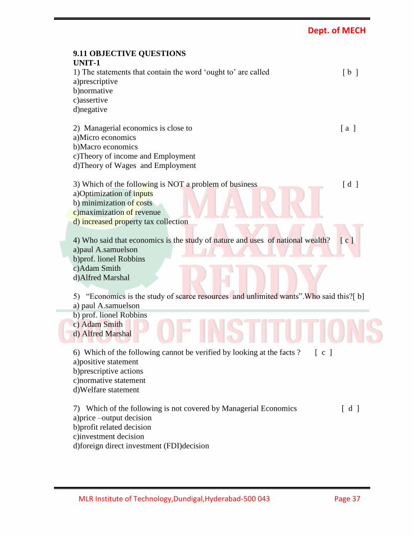
9.11 OBJECTIVE QUESTIONS
UNIT-1
1) The statements that contain the word ‘ought to’ are called [ b ]
a)prescriptive
b)normative
c)assertive
d)negative
2) Managerial economics is close to [ a ]
a)Micro economics
b)Macro economics
c)Theory of income and Employment
d)Theory of Wages and Employment
3) Which of the following is NOT a problem of business [ d ]
a)Optimization of inputs
b) minimization of costs
c)maximization of revenue
d) increased property tax collection
4) Who said that economics is the study of nature and uses of national wealth? [ c ]
a)paul A.samuelson
b)prof. lionel Robbins
c)Adam Smith
d)Alfred Marshal
5) “Economics is the study of scarce resources and unlimited wants”.Who said this?[ b]
a) paul A.samuelson
b) prof. lionel Robbins
c) Adam Smith
d) Alfred Marshal
6) Which of the following cannot be verified by looking at the facts ? [ c ]
a)positive statement
b)prescriptive actions
c)normative statement
d)Welfare statement
7) Which of the following is not covered by Managerial Economics [ d ]
a)price –output decision
b)profit related decision
c)investment decision
d)foreign direct investment (FDI)decision

Dept. of MECH
MLR Institute of Technology,Dundigal,Hyderabad-500 043 Page 38
8) The pre-requisite for rational decision making is [ b ]
a)logical analysis of one’s choices without error
b)consistency between goals and choices
c)rigidly defined choices
d) choices not involving any trade-offs
9 ) Which of the following is a normative statement ? [ a ]
a)Reducing inequality should be a major priority for mixed economies
b) Reducing inequality Would be a major priority for mixed economies
c) Reducing inequality could be a major priority for mixed economies
d) Reducing inequality might be a major priority for mixed economies
10) Which of the following indicates micro approach from national perspective ?
[ a ]
a)lock out in a factory b)per capita income of the country c)total investments in india
d)none
UNIT-2
1. Who explained the “Law of Demand”? ( c )
(a) Joel Dean (b) Cobb-Douglas
(c) Marshall (d) C.I.Savage & T.R.Small
2. Demand Curve always ________ sloping. ( c )
(a) Positive (b) Straight line (c) Negative (d) Vertical
3. Geffen goods, Veblan goods and speculations are exceptions to___. ( c )
(a) Cost function (b) Production function
(c) Law of Demand (d) Finance function
4. Who explained the “Law of Demand”? ( c )
(a) Cobb-Douglas (b) Adam smith
(c) Marshall (d) Joel Dean
5. When PE = (Price Elasticity of Demand is infinite), we call it ___. ( c )
(a) Relatively Elastic (b) Perfectly Inelastic
(c) Perfectly Elastic (d) Unit Elastic
6. Income Elasticity of demand when less than ‘O’ (IE = O), it is
termed as _______. ( c )
(a) Income Elasticity less than unity (b) Zero income Elasticity
(c) Negative Income Elasticity (d) Unit Income Elasticity
7. The other name of inferior goods is _______. ( c )
(a) Veblan goods (b) Necessaries
(c) Geffen goods (d) Diamonds

Dept. of MECH
MLR Institute of Technology,Dundigal,Hyderabad-500 043 Page 39
8. Estimation of future possible demand is called ______. ( c )
(a) Sales Forecasting (b) Production Forecasting
(c) Income Forecasting (d) Demand Forecasting
9. How many methods are employed to forecast the demand ( c )
(a) Three (b) Four (c) Two (d) Five
10. What is the formula for Price Elasticity of Demand? ( c )
(a) % of change in the Price (b) % of change in the Demand
% of change in the Demand % of change in the Income
(c) % of change in the Demand (d) % of change in the Demand of ‘X’
% of change in the Price % of change in the Price of ‘Y’
11. When a small change in price leads great change in the quantity demand,
We call it ________. ( c )
(a) Inelastic Demand (b) Negative Demand
(c) Elastic Demand (d) None
12. When a great change in price leads small change in the quantity demand,
We call it ________.
( c )
(a) Elastic Demand (b) Positive Demand
(c) Inelastic Demand (d) None
13. “Coffee and Tea are the ________ goods”. ( c )
(a) Relative (b) Complementary
(c) Substitute (d) None
14. Consumers Survey method is one of the Survey Methods to forecast the__. ( c )
(a) Sales (b) Income
(c) Demand (d) Production
15. What is the formula for Income Elasticity of Demand? ( c )
(a) % of change in the Income (b) % of change in the Demand
% of change in the Demand % of change in the Price
(c) % of change in the Demand (d) % of change in the Demand of ‘X’
% of change in the Income % of change in the Price of ‘Y’
16. What is the formula for Cross Elasticity of Demand? ( c )
(a) % of change in the Price of ‘X’ (b) % of change in the Demand
% of change in the Demand of ‘Y” % of change in the Price
(c) % of change in the Demand of ‘X’ (d) % of change in the Demand
% of change in the Price of ‘Y’ % of change in the Income

Dept. of MECH
MLR Institute of Technology,Dundigal,Hyderabad-500 043 Page 40
17. When PE = 0 (Price Elasticity of Demand is Zero), we call it ___. ( c )
(a) Relatively Elastic demand (b) Perfectly Elastic demand
(c) Perfectly Inelastic demand (d) Unit Elastic demand
18. When PE =>1 (Price Elasticity of Demand is greater than one),
We call it ___. ( c )
(a) Perfectly Elastic demand (b) Perfectly inelastic demand
(c) Relatively Elastic demand (d) relatively inelastic demand
19. When PE =<1 (Price Elasticity of Demand is less than one),
We call it ___. ( c )
(a) Perfectly inelastic demand (b) Relatively Elastic demand
(c) Relatively inelastic demand (d) perfectly Elastic demand
20. When PE =1 (Price Elasticity of Demand is one), we call it ___. ( c )
(a) Perfectly Elastic demand (b) Perfectly inelastic demand
(c) Unit elastic demand (d) Relatively Elastic demand
21. When Income Elasticity of demand is Zero (IE = 0), It is termed as ___. ( c )
(a) Negative Income Elasticity (b) Unit Income Elasticity
(c) Zero Income Elasticity (d) Infinite Income Elasticity
UNIT-3
1) Isoquants are also called ( a )
A) Isoproduct curves B) isocost curves C) price difference curve D) indifference
curve
2) Production function is not a factor of ( c )
A) Land B) Labour C) cost of capital D) Organization
3) If the level of production of changes the total cost changes and thus isocost curve ( b )
A) Moves downwards B) Moves upwards C) Moves in a linear fashion
D) Moves in a linear fashion
4) In cob-Douglas production function “k” refers to ( c )
A) Land B) Labour C) Capital D) Organization
5) The difference between the total revenue and total cost is called ( c )
A) Cost of production B) Cost of capital C) Profit D) Capital
6) Long run cost curves are called ( d )
A) Operating curves B) Fixed curves C) Variable curves D) planning curves
7) Which of the following are fixed in the short run? ( c )
A) Variable costs B) Semi variable costs C) Fixed costs D) semi fixed costs

Dept. of MECH
MLR Institute of Technology,Dundigal,Hyderabad-500 043 Page 41
8) When do the fixed costs vary? ( b )
A) In the short run B) In the long run C) In 2 years D) Less than 2 years
9) Which of the following level of production denotes break-even point? ( a )
A) Minimum B) Maximum C) Constant D) Diminishing
UNIT-4
1. Organisation management and control are closely held by ( a )
(a) sole trader (b) departmenttal undertaking
(c) patnership (d) joint stock company
2. The closere of patenership is called ……….. ( d )
(a) resolution (b) revolution
(c) solution (d) dissolution
3. To start a patenership firm a minimum of……… and maximum of……….is required
to carry on non-banking business. ( d )
(a)2 and 10 (b) 7 and unlimited
( c) 2 and 50 (d) 2 and 20.
4. Indian companies Act was enacted in ( d )
(a) 1956 (b) 1936
(c) 1947 (d) 1950
5. F is a sole properater ,D is admitted as a patner where D does not bring any capital
then, ( a )
(a) D and F are patners (b) D is not patner as no capital is brought in
(c) D is to be treated as an employee (d) F is the principal
6. A patner who lends his name to the firm without having any real interest is called as
…… ( c )
(a) Ostensible patner (b) Slepping patner or dormant patner
(c) Nominal patner (d) Patner by Estoppel
7 . Environment is basically ………… in nature and the business firm is … ( d )
(a) progressive,prospective (b) progressive,monetary
(c) micro,macro (d) macro,micro
8. SLR refers to ( c )
(a) Standard Lending rate (b) Statutory Lending Ratio
(c) Statutory Liquidity ratio (d) Statutory Rate
9. Globalisation is characterised by ( a )
(a) reduction of trade barriers (b) reduction of performance barrier
(c) ineffective environment (d)dispersed flow techonology
10. Monopolies are done away with ( b )
(a) taxation policy (b) deregulation policy
(c) monetary policy (d) fiscal policy

Dept. of MECH
MLR Institute of Technology,Dundigal,Hyderabad-500 043 Page 42
UNIT-5
1. The structure of market is not based on ________ ( d )
a) degree of seller concentration b)degree of buyer concentration
c)degree of product differentiation d)condition of exit from market
2. Perfect competition is based on ______ ( d )
a)few numbers of buyers and sellers b)heterogenous products and services
c)each firm is a price maker d)perfect mobility of factors of production
3. In a perfect competition,the demand curve for an individual firm is horizontal and ( b )
a)perfectly inelastic b)perfectly elastic
c)unit elasticity d)none of the above
4. Under perfect competition, the price is equal to ( a )
a) AR=MR b)AR>MR
c) MR>AR d)MR not equal to AR
5. Based on number of sellers,imperfect markets are categorized as ( c )
a) monopsony b) duopsony
c)monopolistic competition d) oligopsony
6. Which of the following refers to a positin where a firm enjoys maximum profits and
has no incentive either to reduce or increase its output level? ( c )
a)break even point b)point of inference
c)equilibrium point d)sensitivity point
7. Price in long run is called as ( d )
a)standard price b)retail price
c)market price d)normal price
8. The basis of price discrimination is not due to ( d )
a)purchasing power b)preferential pricing
c)differential pricing d) none of the above
9. Monopoly is not socially desirable as ( d )
a)efficient allocation of resources
b)lessen the gap of rich and poor
c)extend the slope for research and development
d)it leads to exploitation of consumers
10. Which of the following is not feature of monopoly? ( d )
a)single firm b)incudes no close substitutes nor competitors
c)products with elastic demand d)certain statutory privileges

Dept. of MECH
MLR Institute of Technology,Dundigal,Hyderabad-500 043 Page 43
9.12 TUTORIAL QUESTIONS
UNIT-I 1) Define managerial economics illustrate? How it helps in solving managerial problems?
2) Define managerial economics explain its nature and scope?
3) Explain the nature of demand what could be the different variations in the nature of
demand?
4) What is demand function? Hoe do you determine it?
5) Differentiate extension in demand and increase in demand illustrate ?
UNIT-II 1) What do you understand by elasticity of demand? Explain the factors governing it?
2) Explain how do you measure elasticity of demand. illustrate how do you interpret the
different types of elasticity ?
3) For the following series of observations obtain 5 yearly cantered moving average
S.No 1 2 3 4 5 6 7 8 9 10 11 12
Demand 100 100 100 100 100 20 100 100 100 100 100 100
4) What do you understand by demand forecasting explain different methods of demand
forecasting explain different methods of demand forecasting?
5) .”statistical and mathematical techniques complicate the process of demand forecasting
do you agree support your answer?
UNIT-III 1) Define production function? How can a producer find it useful Illustrate?
2) Discuss the economics of scale that occur to an firm?
3) Define cost. Explain the different cost concepts used in the process of cost analysis?
4) Explain how the short run and long run influence the cost.
5) How cost output relationship helps the entrepreneurs in expansion decision?
UNIT-IV 1) Differentiate between perfect and imperfect markets
2) Explain how the price is determine in case of perfect competition illustrate?
3) Explain any four methods of pricing based on strategy?
4) What strategies do you recommend for the markets with stiff competition conditions?
5) A firm has a fixed cost of Rs 10,000. Selling price per unit is Rs 5. and variable cost per
unit is Rs 3.
a. Determine Break Even Point in terms of volume and also sales value
b. Calculate the margin of safety considering that the actual production is 8000
units.
UNIT-V 1) Discuss the factors affecting the choice of form of business organization.
2) What do u understand by joint stock company? Do you think the criticism leveled against
it is correct?

Dept. of MECH
MLR Institute of Technology,Dundigal,Hyderabad-500 043 Page 44
3) What do you understand by liberalization ,privatization and globalization ? explain their
impact on the Indian economy in the recent years.
4) What do you mean by ‘privatization’? explain different forms in which privatization can
be initiated.
5) ‘globalization is a means of attaining international standard of living ‘. Do you agree with
this statement ? support your answer.
9.13 ASSIGNMENT QUESTIONS
UNIT-I 1. Explain the nature of demand what could be the different variations in the nature of
demand?
2. What is demand function? Hoe do you determine it?
3. Define managerial economics illustrate? How it helps in solving managerial problems?
UNIT-II 1. What do you understand by elasticity of demand? Explain the factors governing it?
2. Explain how do you measure elasticity of demand. illustrate how do you interpret the
different types of elasticity ?
3. What do you understand by demand forecasting explain different methods of demand
forecasting explain different methods of demand forecasting?
UNIT-III 1. Discuss the economics of scale that occur to an firm?
2. Define cost. Explain the different cost concepts used in the process of cost analysis?
3. Explain how the short run and long run influence the cost.
UNIT-IV 1. Explain how the price is determine in case of perfect competition illustrate?
2. What strategies do you recommend for the markets with stiff competition conditions?
3. Explain any four methods of pricing based on strategy?
UNIT-V 1. What do you understand by liberation ,privatization and globalization ? explain their
impact on the indian economy in the recent years.
2. What do you mean by ‘privatization’? explain different forms in which privatization
can be initiated.
3. ‘globalization is a means of attaining international standard of living ‘. Do you agree
with this statement ? support your answer.

Dept. of MECH
MLR Institute of Technology,Dundigal,Hyderabad-500 043 Page 45
10. ENGINEERING METROLOGY 10.1 COURSE DESCRIPTION FORM
Course Title ENGINEERING METROLOGY
Course Code A50318
Regulation R13 – JNTUH
Course Structure Lectures Tutorials Practicals Credits
4 1 - 4
Course Coordinator G.Hima Bindu, K.Shravan Kumar,
Team of Instructors M.Anil Kumar
COURSE OVERVIEW:
To provide a basic understanding of the wide range of activities encompassed by
personnel working in standards and calibration laboratories. It covers the measurement
process, types and correct use of measurement and test equipment, and measurement
standards. It provides an opportunity for students to learn about measurement uncertainty
and risk analysis. The course includes the procedures necessary to set up and to have
knowledge on calibration.
At the end of this subject the student is expected it is expected to enforce, validate and
verify predefined standards for traceability, accuracy, reliability, and precision. All of
these are factors that would affect the validity of measurement. Although these standards
vary widely, these are mandated by the government, the agencies, and some treaties.
Consequently, these standards are verified and tested against a recognized quality system
in calibration laboratories.
10.2 PREREQUISITES:
Level Credits Periods / Week Prerequisites
UG 4 5
Production technology,
Machine Drawing

Dept. of MECH
MLR Institute of Technology,Dundigal,Hyderabad-500 043 Page 46
10.3 MARKS DISTRIBUTION:
Sessional Marks
University End Total
Exam marks marks
Mid Semester Test There shall be two midterm examinations. Each midterm examination consists of subjective type and objective type tests. The subjective test is for 10 marks of 60 minutes duration. Subjective test of shall contain 4 questions; the student has to answer 2 questions, each carrying 5 marks. The objective type test is for 10 marks of 20 minutes duration. It consists of 10 Multiple choice and 10 objective type questions, the student has to answer all the questions and each carries half mark. First midterm examination shall be conducted for the first two and half units of syllabus and second midterm examination shall be conducted for the remaining portion.
75 100
Sessional Marks
University End Total
Exam marks marks
Assignment Five marks are earmarked for assignments. There shall be two assignments in every theory course. Marks shall be awarded considering the average of two assignments in each course.
10.4 EVALUATION SCHEME:
S. No Component Marks Duration
1 I Mid Examination 80 minutes 20
2 I Assignment - 05
3 II Mid Examination 80 minutes 20
4 II Assignment - 05
5 External Examination 3 hours 75
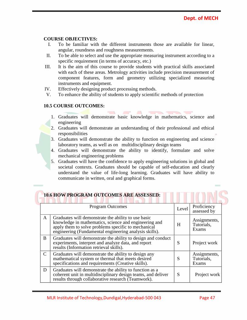
Dept. of MECH
MLR Institute of Technology,Dundigal,Hyderabad-500 043 Page 47
COURSE OBJECTIVES:
I. To be familiar with the different instruments those are available for linear,
angular, roundness and roughness measurements.
II. To be able to select and use the appropriate measuring instrument according to a
specific requirement (in terms of accuracy, etc.)
III. It is the aim of this course to provide students with practical skills associated
with each of these areas. Metrology activities include precision measurement of
component features, form and geometry utilizing specialized measuring
instruments and equipment.
IV. Effectively designing product processing methods.
V. To enhance the ability of students to apply scientific methods of protection
10.5 COURSE OUTCOMES:
1. Graduates will demonstrate basic knowledge in mathematics, science and
engineering
2. Graduates will demonstrate an understanding of their professional and ethical
responsibilities
3. Graduates will demonstrate the ability to function on engineering and science
laboratory teams, as well as on multidisciplinary design teams
4. Graduates will demonstrate the ability to identify, formulate and solve
mechanical engineering problems
5. Graduates will have the confidence to apply engineering solutions in global and
societal contexts. Graduates should be capable of self-education and clearly
understand the value of life-long learning. Graduates will have ability to
communicate in written, oral and graphical forms.
10.6 HOW PROGRAM OUTCOMES ARE ASSESSED:
Program Outcomes Level
Proficiency assessed by
A Graduates will demonstrate the ability to use basic knowledge in mathematics, science and engineering and apply them to solve problems specific to mechanical engineering (Fundamental engineering analysis skills).
H Assignments, Tutorials, Exams
B Graduates will demonstrate the ability to design and conduct experiments, interpret and analyze data, and report results (Information retrieval skills).
S Project work
C Graduates will demonstrate the ability to design any mathematical system or thermal that meets desired specifications and requirements (Creative skills).
S Assignments, Tutorials, Exams
D Graduates will demonstrate the ability to function as a coherent unit in multidisciplinary design teams, and deliver results through collaborative research (Teamwork).
S Project work

Dept. of MECH
MLR Institute of Technology,Dundigal,Hyderabad-500 043 Page 48
E Graduates will demonstrate the ability to identify, formulate and solve mechanical engineering problems of a complex kind (Engineering problem solving skills).
H Assignments, Exams
F Graduates will demonstrate an understanding of their professional and ethical responsibilities, and use technology for the benefit of mankind(Professional integrity).
H Assignments, Tutorials,
G Graduates will be able to communicate effectively in both verbal and written forms (Speaking / writing skills).
S --
H Graduates will have the confidence to apply engineering solutions in global and national contexts (Engineering impact assessment skills).
H Assignments, Tutorials,
I Graduates should be capable of self-education and clearly understand the value of life-long learning (Continuing education awareness).
H Assignments, Tutorials,
J Graduates will develop an open mind and have an understanding of the impact of engineering on society and demonstrate awareness of contemporary issues (Social awareness).
S --
K Graduates will be familiar with applying software methods and modern computer tools to analyze mechanical engineering problems (Software hardware interface).
H --
L Graduates will have the ability to recognize the importance of professional development by pursing post graduate studies or face competitive examinations that offer challenging and rewarding careers in Mechanical Engineering (Successful career andimmediate employment).
S Gate exam, Job interviews
M Graduate will be able to design a system to meet desired needs within environmental, economic, political, ethical health and safety, manufacturability and management knowledge and techniques to estimate time, resources to complete project (Practical engineering analysis skills).
H Assignments, Tutorials, Exams
N = N = None S = Supportive H = Highly Related
10.7 SYLLABUS
UNIT-1
Systems of limits and fits: Introduction, normal size, tolerance limits, deviations,
allowance, fits and their types - unilateral and bilateral tolerance system, hole and shaft
basis systems – interchangeability and selective assembly. Indian standard Institution
system - British standard system, International Standard system for plain ad screwed
work.
UNIT - II
LINEAR MEASUREMENT : Length standard, line and end standard, slip gauges -
calibration of the slip gauges, Dial indicator, micrometers.MEASUREMENT OF
ANGLES AND TAPERS : Different methods - Bevel protractor - angle slipgauges –
spirit levels - sine bar - Sine plate, rollers and spheres used to determine the tapers.

Dept. of MECH
MLR Institute of Technology,Dundigal,Hyderabad-500 043 Page 49
LIMIT GAUGES : Taylors principle - Design of go and No go gauges, plug ring, snap,
gap, taper, profile and position gauges.
UNIT - III
OPTICAL MEASURING INSTRUMENTS : Tool maker's microscope and its uses -
collimators, optical projector - optical flats and their uses, interferometer.
FLAT SURFACE MEASUREMENT : Measurement of flat surfaces - instruments used -
straight edges- surface plates - optical flat and auto collimator.
UNIT - IV
SURFACE ROUGHNESS MEASUREMENT : Differences between surface roughness
and surfacewaviness-Numerical assessment of surface finish - CLA,R, R.M.S Values - Rz
values, Rz value, Methodsof measurement of surface finish-profilograph. Talysurf, ISI
symbols for indication of surface finish.
UNIT-V
SCREW THREAD MEASUREMENT : Element of measurement - errors in screw threads
- measurementof effective diameter, angle of thread and thread pitch, profile thread
gauges.
MEASUREMENT THROUGH COMPARATORS : Comparators - Mechanical, Electrical
and ElectronicComparators, pneumatic comparators and their uses in mass production.
MACHINE TOOL ALIGNMENT TESTS : Requirements of Machine Tool Alignment
Tests, Alignmenttests on lathe, milling, drilling machine tools.. Preparation of acceptance
charts.
GEAR MEASUREMENT: Gear measuring instruments, Gear tooth profile measurement.
Measurement of diameter, pitch pressure angle and tooth thickness.Coordinate Measuring
Machines: Types of CMM, Role of CMM, and Applications of CMM.
TEXT BOOKS :
1. Engineering Metrology / I C Gupta./ Danpath Rai
2. Engineering Metrology / R.K. Jain / Khanna Publishers
REFERENCES :
1. BIS standards on Limits & Fits, Surface Finish, Machine Tool Alignment etc.

Dept. of MECH
MLR Institute of Technology,Dundigal,Hyderabad-500 043 Page 50
10.8 COURSEPLAN:
At the end of the course, the students are able to achieve the following course learning
outcomes.(The course plan is meant as a guideline. There may probably be changes.
Lecture
No.
Course Learning
Outcomes Topics to be covered Reference
1
Classify of Measuring
Instruments and
Measuring methods
Basic measuring elements, classification
of measuring instruments and measuring
methods
T1
2 Define Limit, Normal
Size , Allowance
Limits , upper limit, lower limit, tolerance
normal size, deviations and allowance.
T1
3 List Out the types of
Writing Tolerance
System of limits. Unilateral system,
Bilateral system. Maximum metal limit,
Least metal limit.
T1
4 Classify the Types of
Fits
Fit. Classification of fits, clearance fit,
interference fit and transition fit.
T1
5 Illustrate the Fits and
Limits Terminology for fit and limits. T1
6
Describe
interchangeability,
selective assembly.
System obtaining for different types of
fit. Hole basis system and Shaft basis
system, interchangeability, selective
assembly.
T1
7
Define ISI system,
British standard
system,
ISI system, British standard system,
International standard system for plain
and screwed work, problems solved .
T1
8
Evaluate Converting
hole based system fit
into an equivalent shaft
based fit.
Converting hole based system fit into an
equivalent shaft based fit.
T1
9 Write the Basic Units
Linear measurement. Basic units. Meter
standard, yard standard. T1
10
Distinguish Between
Line standard and end
standard
Line standard, end standard, calibration
of end standard T1

Dept. of MECH
MLR Institute of Technology,Dundigal,Hyderabad-500 043 Page 51
11
Use of Slip gauges For
Linear Measurement
Slip gauges, calibration of slip gauges,
grade of slip gauges, wringing and care
of slip gauges.
T1
12 Identify the Errors In
Dial Indicator Dial indicator uses and sources of errors. T1
16+ Identify the Errors In
Micrometer Micrometers uses and sources of errors. T1
14
List out the
Instruments for
measurement of
Angles
Measurement of angles and tapers. Sine
bar, slip gauges bevel protractor. T1
15
Explain The Principle
of Sprit Level
Spirit level, sine plate. Rollers and
spheres used to determine the angle of
tapers.
T1
16 Use of Angle Gauges Angle gauges. Problems solved. T1
17
Demonstrate how to
check the angle of taper
workspace and holes.
To check the angle of taper workspace
and holes. Problems solved. T1
18
List out the types of
Gauges
Gauges, types of gauges, plug, ring, snap
and plane gauges.
T1
19
Apply The Taylor’s
Principle in Designing
Of gauges
Taylor's principle- Design of GO and
NOGO gauges.
T1
20 Explain Optical
measuring instruments. Optical measuring instruments. T2
21
Illustrate the Working
of Tool maker's
microscope
Tool maker's microscope and its uses. T2
22
List Out the
Instruments for Flat
surface measurement
Optical flat. Flat surface measurement
Surface plate, knife edge and straight
edge.
T2
.
23
Demonstrate the
Working of Optical
projector
Optical projector and Auto collimeter. T2

Dept. of MECH
MLR Institute of Technology,Dundigal,Hyderabad-500 043 Page 52
24 Describe Flat surface
measurement . Flat surface measurement . T2
25
Distinguish Between
knife edge and straight
edge.
knife edge and straight edge. T2
26 Discuss Interferometer Interferometer and their uses. T2
27
Distinguish between
surface roughness and
surface Waviness
Differences between surface roughness
and surface Waviness
T2
28
Evaluate of surface
finish,
Evaluation of surface finish, CLA R.MS
and Rz values .
T2
29 Define Geometrical
irregularities. Geometrical irregularities. T2
30
Write Numerical
assessment of surface
finish.
Numerical assessment of surface finish. T2
31
List out Direct
instrument methods.
Direct instrument method. Stylus,
applications.
T2
32
Explain the working
principle of
Profilometer
Profilometer, Tarmlinson surface meter
.applications
T2
33
Explain the working
principle of Taylor-
Hobson talysurf.
Taylor-Hobson talysurf. . T2
34
Write the ISI symbol
for indication of
surface finish
ISI symbol for indication of surface finish T2
35 Identify the Different
Comparators
Introduction to comparators. T2
36
Classify the
Mechanical
Comparators
Comparators - Mechanical comparators,
applications and advantages
T2
37
Distinguish Between
Electrical and
Electronic
Electrical and Electronic Comparators, T2

Dept. of MECH
MLR Institute of Technology,Dundigal,Hyderabad-500 043 Page 53
Comparators applications and advantages.
38
Explain Pneumatic
comparators
Pneumatic comparators and their uses in
mass production
T2
39
State the Advantages
of Pneumatic
comparators over
Mechanical
comparators
Advantages of Pneumatic comparators
over Mechanical comparators
T2
40
Discuss the Screw
thread measurement
Introduction to screw thread
measurement.
T2
41 Identify the Errors in
screw thread
Errors in screw thread. T2
42
Explain the process of
Measurement of
effective diameter.
Measurement of effective diameter. T2
43
Demonstrate how
thread angle can be
measured
Angle of thread and thread pitch
measurement.
T2
44 Describe about Profile
thread gauges.
Profile thread gauges. T2
45 Discus the Process Of
Best size method.
Best size method. T2
46 Use of machine tool
Alignment Test
Requirements of machine tool Alignment
Test
T2
47
Describe how
Alignment test on
Lathe machine, Milling
machine can be done
Alignment test on Lathe machine,
Milling machine
T2
48
Explain the process
Alignment Test On
Drilling Machine
Alignment Test On Drilling Machine T2
49 Write the Preparation
of Acceptance Charts
Preparation of Acceptance Charts T2
50 Classify the Gear Gear measuring Instruments T2

Dept. of MECH
MLR Institute of Technology,Dundigal,Hyderabad-500 043 Page 54
measuring Instruments
51
Illustrate the Gear
Tooth profile
Measurement
Gear Tooth profile Measurement T2
52 Define Pitch Pressure
angle
Measurement of Diameter, Pitch Pressure
angle
T2
53
Discuss the process of
Measurement of tooth
thickness
Measurement of tooth thickness T2
54 Classify the types of
CMM
Types of CMM T2
55 Discuss the role of
CMM
Role of CMM
56 List out the
Applications of CMM
Applications of CMM
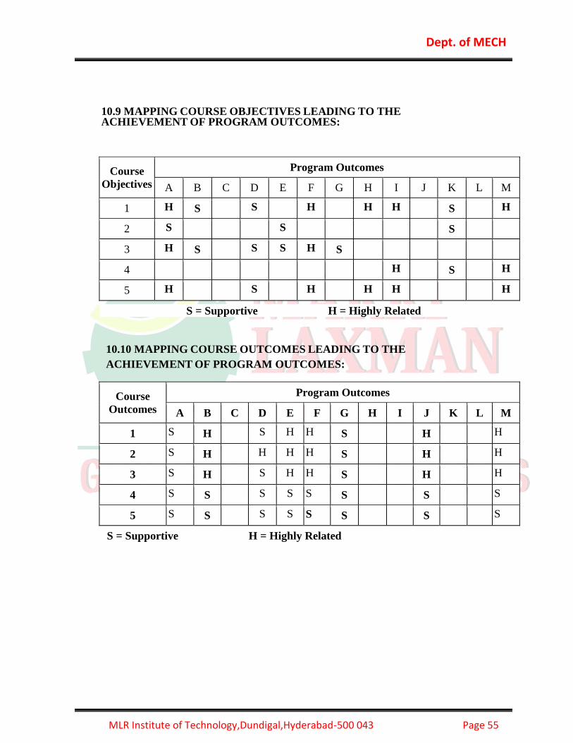
Dept. of MECH
MLR Institute of Technology,Dundigal,Hyderabad-500 043 Page 55
10.9 MAPPING COURSE OBJECTIVES LEADING TO THE ACHIEVEMENT OF PROGRAM OUTCOMES:
Course
Objectives
Program Outcomes
A B C D E F G H I J K L M
1 H S S H H H S H
2 S S S
3 H S S S H S
4 H S H
5 H S H H H H
S = Supportive H = Highly Related
10.10 MAPPING COURSE OUTCOMES LEADING TO THE
ACHIEVEMENT OF PROGRAM OUTCOMES:
Course
Outcomes
Program Outcomes
A B C D E F G H I J K L M
1 S H S H H S H H
2 S H H H H S H H
3 S H S H H S H H
4 S S S S S S S S
5 S S S S S S S S
S = Supportive H = Highly Related

Dept. of MECH
MLR Institute of Technology,Dundigal,Hyderabad-500 043 Page 56
10.11 OBJECTIVE QUESTIONS
UNIT-1
1. Allowance in limits and fits refers to. [ B ]
a) Axiom clearance between shaft and hole b) Minimum clearance between shaft and
hole
c) Difference between maximum and minimum size of hole d) Difference between
maximum and
minimum size of shaft
2. The fit on a hole shaft system is specified as 117-s6. The type of fit is [
C ]
a) Clearance fit b) Transition fit c) Interference fit d) Wringing fit
3. The lower limit of shaft is greater than the upper limit of the hole, the fit is.
[ C ]
a) Clearance fit b) Transition fit c) Interference fit d) Wringing fit
4. In the specification of dimensions and fits [ C ]
a) Allowance is equal to the bilateral tolerance b) Allowance is equal to the unilateral
tolerance c) Allowance is independent of tolerance d) Allowance is equal to
the difference between Maximum and Minimum dimension specified by the tolerance.
5. When the clearance between the mating parts are zero, the fit is. [ A ]
a) Slide fit b) Easy Slide fit c) Running fit d) Loose running fit
6. When tolerance is varies only one side of the basic size is called [ B ]
a) Bilateral tolerance b) Unilateral tolerance c) Allowance d) Clearance
7. Prototype meter is made of [ B ]
a) Aluminum b) Platinum and Iridium alloy c) Titanium d) Steel
8. In tail stock which type of fit is used [ A ]
a) Slide fit b) Easy Slide fit c) Running fit d) Loose Running fit
9. What is defined as permissible variation in dimension of a part [ C ]
a) Allowance b) Clearance c) Tolerance d) Limit
10. The lower limit of shaft is greater than the upper limit of the hole, the fit is.
[ C ]
a) Clearance fit b) Transition fit c) Interference fit d) Wringing fit
11. International prototype meter is [ A ]

Dept. of MECH
MLR Institute of Technology,Dundigal,Hyderabad-500 043 Page 57
(a)100cm long (b)102cm long
(c) 38 inches long (d)1cm long
12. Metrology is a science [ B ]
(a) Instruments (b)measurement
(c) Length (d)angles
13. The algebraic difference between the result of measurement and true value of
the
Quantity [ B ]
(a) Limit (b) tolerance
(c) Error (d) clearance
14. Degree of repeatability of the measuring process [ C ]
(a)accuracy (b)limit
(c) Precession (d) magnification
15. Following are process of measurement [ D ]
(a)measurand (b)reference
(c) comparator (d)all the above
16. the standard size for the part and is the same for both the hole and its shaft. [ B
]
(a)Nominal Size (b)Basic Size
(c)Actual Size (d)all the above
17. Differential screw micro meter is used [ A ]
(a). To give direct indication of difference between two reading (b). For digital
readout
(c). To measure gap between grooves (d). For very high
degree of accuracy
18. Which of the following can be used to scribe lines parallel to the edges of a part
[ C ]
(a). Venire calipers (b). Screw gauge (c). Divider (d). Hermaphrodite
caliper
19. The permissible variation in dimension is called as
[ B ]
(a)tolerance (b)limit (c)fit (d)all the above
20.for shaft the relationship of deviation with tolerance is given by IT=
[ A ]
(a)es-ei (b)ES-EI (c)HL-LL (d)es+ei
UNIT-II
1. If a gauge is made as an exact copy of mating part of the component to be
checked, it [ B ]
a) Limit gauge b) Standard gauge c)Work shop gauge d) Inspection gauge
2. When using a micrometer a constant measuring pressure can be obtained by
using the [ B ]
a) Thimble b) Ratchet c) Spindle d)Roughness

Dept. of MECH
MLR Institute of Technology,Dundigal,Hyderabad-500 043 Page 58
3. Feeler gauge is used for [ B ]
a) Clearance in hole b) Clearance between two mating parts c)Clearance in shaft d)
none
4. Slip gauges are called [ C ]
a) Angle gauges b) feeler gauge c) Gauge blocks d) All the
above
5. Relief holes are provided to reduce the _______ of the sine bar. [ A ]
a) Weight b) Length c) Diameter d) Size
6. Telescopic gauge are used for [ B ]
a) External diameter of hole, slot and grooves b) Internal diameter of hole , slot and
grooves
c) Both A and B d) Any one of the Above
7. A sine bar is specified by
[ B ]
(a). Its total length (b). The centre distance between the two rollers
(c). The size of the rollers (d). The distance between rollers and
upper surface
8. The allowance recommended by B.S.I for wear on solid ring and plug gauge is
[ B ]
a) 0.1mm b) 0.005mm c) 0.5mm d) 0.05mm
9. Ring gauges are used for [ D ]
a) Measuring any dimension b) Checking shaft diameter
c) Checking bore diameter d) Measuring outside dimension
10. Which of the following can be used to scribe lines parallel to the edges of a part
[ C ]
a) Vernier callipers b) Screw gauge c) Divider d) Hermaphrodite caliper
11.Dial Indicators are used for [ A ]
(a)Thickness Measurement (b) Height Measurement
(c)Depth Measuremnt (d)Diameter Measurement
12. GO gauge checks the Maximum Material Condition (MMC)
13. NOT-GO gauge checks the Least Material Condition (LMC)
14. In unilateral system; the gauge tolerance zones lie entirely within the [ C ]
(a) Maximum Material Condition (b)Minimum Material Condition

Dept. of MECH
MLR Institute of Technology,Dundigal,Hyderabad-500 043 Page 59
(c)Tolerance Zone (d) All of the above
15. Limit Gauges Do not indicate the actual size of the component
16.The following type is not a gauge [ D ]
(a)Ring (b)Snap (c)Plug (d)Scale
17.Snap gauges are used for [ A ]
(a)External dimensions (b)Internal dimensions (c)Threads (d)Taper angle
18.A positional gauge is to check the ------------------------ [ C ]
(a)location (b)height (c)distance (d)length
19.bevel protractor is used to measure the [ A ]
(a)angle (b)straightness (c)flatness (d)parallelism
20.Spirit levels are used to [ D ]
(a)check the level (b)check the thread (c)check the height (d)check the depth
UNIT-III
1. Auto collimator is used to check [ C ] a)
Roughness b) Flatness c) Angle d) Automobile balance
2. A monochromatic light consists of rays of 5.9x10.7m wavelength.
3. Interference phenomenon can be observed with all type of wave sources of light.
4. The fitter gauge interferometer has Roster prism.
5. Optical flats are made of quartz or silica.
6. the phenomenon of interaction o light waves is called optical.
7. Light is a form of energy being propagated by electromagnetic radiation.
8. If the two rays of the same end points meet at some point, a mutual interference will
occur.
9. Electromagnetic radiation may be represented by Planks curve.
10. Type A optical flat has a single working surface.
11. The parallelism of the working surfaces of type B optical flats can be tested by Fizeau
Interferometer
method.
12. Optical flats are cylindrical in form with the working with [ A ]
(a)Surfaces Flat (b)Rough Surfaces (C) Smooth surfaces (d)all of the above
13. If the optical flat under test has a perfectly flat surface then the fringes observed will be
straight lines are [ B ]
(a)Perpendicular to each other (b)Parallel to each other
(c) Interfere with each other (d) All of the above
14. Interferometers are optical instruments used for measuring flatness and determining the
length of
slip gauges by direct reference to the wavelength of light.
15. This is the oldest type of interferometer [ A ]

Dept. of MECH
MLR Institute of Technology,Dundigal,Hyderabad-500 043 Page 60
(a) Michelson Interferometer (b) N.P.L. Flatness Interferometer
(c) Laser Interferometers (d)Talysurf Interfero meter
16.Beam splitters. These, (like partially silvered mirrors) divide the laser beam into separate
beams along different axes.
17. As the ACLI measures component travel in the direction of laser beam, and if two are
not coincident, then error called -----------will be introduced [ A ]
(a) Cosine error (b)Sine error (c)Parralax error (d)error
18. Beam must never be completely blocked by a solid object,
19. These are used to deflect the light beam around corners on its path from the laser to
each axis.[ B ]
(a)Beam Reflectors (b)Beam Benders (c)Beam Splitters (d)Interferometer
20. These are used for checking the straightness and flatness of parts in conjunction with
the surface plates
and spirit levels [ C ]
(a) Tool Maker’s Microscope (b)Angle Plate (c) V Block (d)optical flat
UNIT-IV
1. The surface irregularities of small wave length are called [ A ]
a) Primary texture b) Secondary texture c) Waviness d) Roughness
2. Secondary texture is also known as Surface waviness
3. Profilometer is measuring for Surface roughness in microns units
4. Surface Roughness value is 1.6 to 8μm then symbol for this ▼▼
5. The roughness is also known as [ A ] (a) primary texture (b) secondary texture (c) both A & B (d) none of the above
6. Surface texture includes. [ C ] (a) roughness (b) waviness
(c) roughness and waviness (d) none of the above
7. The symbol Ra 8.0(2.5) means surface roughness.
8. The waviness is also called as. [ B ]
(a) primary texture (b) secondary texture (c) both A & B (d) none of the above
9. Surface irregularities which occur at infrequent intervals is called Flaw.
10. Profile is defined as the contour of any section through a surface.
11.Lay refers to the predominant direction of the marks visible on the surface.
12.Tomlinson surface meter is a mechanical type equipment
13.Moving coil instrument is mounted above the -------------- [ A ]
(a)Stylus (b)coil (c) magnet (d)table
14. Surface flatness is measured by ---------------------- [ C ]
(a) Micrometer (b) feeler gauge (c) optical flat (d)dial indicator
15.the surface roughness/texture may be obtained by------------------ [ A ]
(a)any production method (b)without removal of material
(c) removal of material by machining (d)by any method
16.for the roughness grade number three, roughness grade symbol consists of -------
[ D ]
(a)four triangles (b)two triangles
(c) Three triangles (d)no triangle
17The roughness value for grade N2 is four.

Dept. of MECH
MLR Institute of Technology,Dundigal,Hyderabad-500 043 Page 61
18.The roughness grade for 50m is 0.05microns
19. Roughness value Ra is given by microns units
20. M-System is a satisfactory means at the point of production
UNIT-V
1. The usual range of magnification obtained in mechanical comparators is [ A ]
a) 250 to 1000 b) 200 to 2000 c) 300 to 1000 d) 350 to 2000
2. -------------------------- comparators are based on the principle of frequency modulation.
[ C ]
a) Mechanical b) Electrical c) Electronic d) Pneumatic
3. The comparator is providing magnification in the range of 500 to 1000, then the
comparator is called as [
D ]
a) Optical b) Pneumatic c) Differential comparator d) Sigma
4. The Johansson mikrokator comparator is also called- Twisted strip
5. The pneumatic gauging is based on Bernoulli’s theory.
6. Optical type of comparator do not require any external agency such as electricity or
air.
7. In mechanical comparator the magnification of the small styles movement is
obtained by means of levers, gears , etc.
8. In reed type mechanical comparator, the gauging head is usually a sensitive , high
quality , dial indicator.
9. Dial indicator is a simplest type of mechanical comparator.
10.Electrical and Electronic comparators depend on their operation on A.C. wheat stone
bridge incorporating galvanometer.
11. If the pitch of the thread is uniform but is longer or shorter than that of its nominal
value the error is called [ B ]
a) Periodic error b) Progressive error c) Drunken error d) Erratic errors
12. In order to measure that all the measurements are made at the same pressure, an -------
indicator is used in measurement of major diameter. [ C ]
a) Dial indicator b) Micrometer indicator c) Fiducial indicator d) Comparator
13. Errors in the flank angle causes a virtual increase in the -------------------- diameter of
a bolt
and a decrease in that of a nut. [ D ]
a) Major Diameter b) Minor diameter c) Virtual diameter d) Effective diameter
14. Diameter of Best size wire is equal to (db) = (p/2) sec x
15. Three wire method can be used to measure Pitch
16. Flank angle is equal to 1-2 times the thread angle.
17. Pitch errors in the thread are classified as root, flank, flank angle,1/2 angle.
18. Thread micrometer can measure pitch of the thread.
19. The angle of ISO metric thread is 600
20. If P is the pitch of the thread the best size wire is equal to pitch dia.

Dept. of MECH
MLR Institute of Technology,Dundigal,Hyderabad-500 043 Page 62
10.12 TUTORIAL QUESTIONS
OBJECTIVES: This course provides a basic understanding of the wide range of activities encompassed
by personnel working in standards and calibration laboratories. It covers the measurement
process, types and correct use of measurement and test equipment, and measurement
standards. It provides an opportunity for students to learn about measurement uncertainty
and risk analysis. The course includes the procedures necessary to set up and to have
knowledge on calibration.
TUTORIAL 1
LIMITS AND FITS
SHORT ANSWER QUESTIONS
S.
No QUESTION
Blooms
Taxonomy
Level
Course
Outcome
1. Draw a sketch and explain minimum and maximum
metal conditions of shaft and hole. Knowledge
2
2. Discuss complete classification of fits. Explain them
with the help of suitable examples. comprehension
2
3. List out the types of assemblies. Knowledge 3
4. Illustrate the need of limit system Application 2
5. Determine about allowance and Tolerance Evaluation 2
6. Define MML Knowledge 1
7. How is a fundamental tolerance represented. Knowledge 1
8. Define limit Knowledge 1
9. What are the two systems of writing tolerance . Knowledge 2
10. What are the types of assemblies. Knowledge 2

Dept. of MECH
MLR Institute of Technology,Dundigal,Hyderabad-500 043 Page 63
LONG ANSWER QUESTIONS
1. Explain about the types of assemblies comprehension
2
2 Interpret the meaning of following type of fit :
(i) H7f6 (ii) H7v5 (iii) H7r6 (iv) H7h6 Knowledge
2
3. Explain unilateral and bilateral tolerance system with
a neat diagram comprehension
2
4. Describe the term normal size, deviation, upper
deviation and lower deviation. Remember 1
5.
A 50mm diameter shaft to made to rotate in a bush.
The tolerance for both shaft and bush are 0.05mm.
Determine the dimension of shaft and bush to give a
maximum clearance of 0.075mm with the hole basis
system.
Evaluation 2
6.
In a hole and shaft assembly of 30mm nominal size
the tolerance for hole and shaft are as specified
below: Hole having upper limit as +0.02 and lower
limit as -0.00mm Shaft having upper limit as –
0.04mm and lower limit as – 0.07mm: Determine (i)
maximum and minimum clearance obtained (ii)
allowance (iii) hole and shaft tolerance (iv) MML of
shaft and hole (v) type of fit.
Evaluation 2
7.
A hole and a mating shaft are to have a nominal size
assembly size of 40mm. the assembly is to have maximum
clearance of 0.15mm and minimum clearance of 0.05mm.
The hole tolerance is 1.5 times the shaft tolerance. Determine
the limits for both hole and shaft by using hole basis and
shaft basis system.
Evaluation 2
8.
Between two mating parts of 100mm basic size the actual
interference fit is to from 0.05 and 0.12mm. The tolerance
for hole is the same as the tolerance of shaft. Find the size of
oth the shaft and the hole (a) hole basis unilateral system (b)
shaft basis unilateral system.
Evaluation
2
9. Draw a conventional diagram of limits and fits and
explainall the terms involved in it
10. Explain how hole, shaft and fit are designed? explain
withsuitable example
comprehension
2
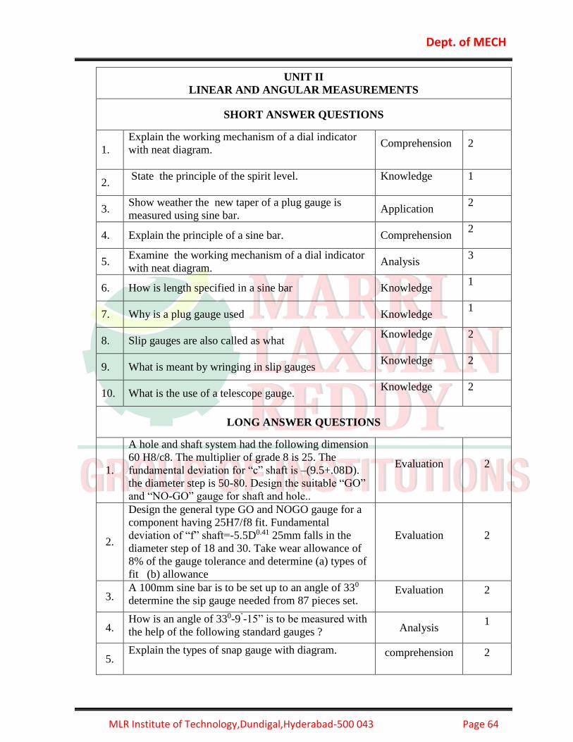
Dept. of MECH
MLR Institute of Technology,Dundigal,Hyderabad-500 043 Page 64
UNIT II
LINEAR AND ANGULAR MEASUREMENTS
SHORT ANSWER QUESTIONS
1.
Explain the working mechanism of a dial indicator
with neat diagram.
Comprehension
2
2. State the principle of the spirit level.
Knowledge
1
3. Show weather the new taper of a plug gauge is
measured using sine bar. Application
2
4. Explain the principle of a sine bar. Comprehension 2
5. Examine the working mechanism of a dial indicator
with neat diagram. Analysis
3
6. How is length specified in a sine bar Knowledge 1
7. Why is a plug gauge used Knowledge 1
8. Slip gauges are also called as what Knowledge
2
9. What is meant by wringing in slip gauges Knowledge
2
10. What is the use of a telescope gauge. Knowledge
2
LONG ANSWER QUESTIONS
1.
A hole and shaft system had the following dimension
60 H8/c8. The multiplier of grade 8 is 25. The
fundamental deviation for “c” shaft is –(9.5+.08D).
the diameter step is 50-80. Design the suitable “GO”
and “NO-GO” gauge for shaft and hole..
Evaluation
2
2.
Design the general type GO and NOGO gauge for a
component having 25H7/f8 fit. Fundamental
deviation of “f” shaft=-5.5D0.41 25mm falls in the
diameter step of 18 and 30. Take wear allowance of
8% of the gauge tolerance and determine (a) types of
fit (b) allowance
Evaluation
2
3. A 100mm sine bar is to be set up to an angle of 330
determine the sip gauge needed from 87 pieces set. Evaluation
2
4. How is an angle of 330-9’-15” is to be measured with
the help of the following standard gauges ? Analysis 1
5. Explain the types of snap gauge with diagram. comprehension
2

Dept. of MECH
MLR Institute of Technology,Dundigal,Hyderabad-500 043 Page 65
6. Give the complete classification of taper gauges with
the help of neat diagram. Remember 1
7. What is wringing? What precautions must take while
wringing slip gauges? Knowledge
2
8.
How do you measure external dovetail, internal
dovetail and angle of dovetail with the help of
precision balls and rollers.
Analysis 1
9. Explain the construction and working of an optical
bevel protractor with neat diagram comprehension
2
10. Explain in detail about plug gauge and snap gauge comprehension
2
UNIT III
OPTICAL MEASURING INSTRUMENTS AND FLAT SURFACE
MEASUREMENTS
SHORT ANSWERS
1. What is an optical flat? Knowledge
2
2. Explain the procedure for flatness measurement on
surface plate.
comprehension
2
3. Determine the principle of an autocollimator with
neat diagram
Evaluation
2
4.
Illustrste some applications of a Tool marker’s
microscope.
Application
4
5. What is the principal of autocollimeter Knowledge
2
6. Draw a line diagram of NPL interferometer Remember 1
7. List out some applications of a Tool marker’s
microscope Remember 1
8. Draw a neat diagram how an auto collimator is
represented
9. What material is used for optical flats Knowledge
2
10. Explain the use of type A optical flat comprehension
2

Dept. of MECH
MLR Institute of Technology,Dundigal,Hyderabad-500 043 Page 66
LONG ANSWER QUESTIONS
1. Explain with neat diagram an optical flat comprehension
2
2. Which prism is used in fitter gauge interferometer
explain?
3. Explain the flat surface measurements. comprehension
2
4. What is the use of a surface plate explain? Knowledge
2
5. Describe in detain the working of an Knife Edge. Remember 1
6. With a neat diagram illustrate an autocollimeter and
its working principal.
7. Explain the NPL interferometer construction. comprehension
2
8. Describe the importance of an optical projector. Remember 1
9. List out the different optical instruments and explain
them. Remember 1
10. What are the applications and advantages of an
optical projector.
Knowledge
2
UNIT IV
SURFACE ROUGHNESS MEASUREMENT
SHORT ANSWER QUESTIONS
1. What is the ISI symbol for indication of surface
finish? Knowledge
1
2. Define waviness Knowledge
1
3. What are the methods used for evaluating the surface
finish? Knowledge
2
4.
How will you represent it , The surface finish on the milled
surface is not to exceed 5micro meter Ra with a cutoff
length 2mm machining allowance 0.5mm and direction of
lay parallel.
Analysis 1
5. Define the Term Primary Texture Knowledge
1
6. What are the different types of Lay. Knowledge
2

Dept. of MECH
MLR Institute of Technology,Dundigal,Hyderabad-500 043 Page 67
7. What is Form Factor Knowledge
2
8. Explain the Principle of Profilometer. comprehension
2
9. How CLA index number is determined? Knowledge
1
10. Draw the Diagram of Surface Texture showing all
the elements Remember 1
LONG ANSWER QUESTIONS
1.
Determine CLA & RMS values, the measurement of
surface roughness heights of successive 10 peaks and
troughs were measured from a datum and were
22,30,45,56,15,55,35,40 microns. If these
measurement were obtained on 15mm length
Evaluation
2
2. Explain the working and usage of Talysurf in surface
roughness measurement.
comprehension
2
3. Explain the method of measurement of surface finish
using profilograph with neat diagram.
comprehension
2
4. Explain the working of Tomlinson Surface Meter
with neat diagram.
comprehension
2
5. 10. Explain the following terms?
i. Roughness ii. Waviness iii. lay.
comprehension
2
6.
Explain the roughness indices terms Ra or CLA, Rz
and RMS values in numerical assessment of
roughness.
comprehension
2
7.
Determine CLA & RMS values, In the measurement
of surface roughness heights of successive 10 peaks
and troughs were measured from a datum and were
33,25,30,19,22,18,27,29,20 microns. If these
measurement were obtained on 10mm length
Evaluation
2
8. Explain the construction and working of a
profilograph for surface roughness measurement.
comprehension
2
9. Explain the working of profilometer with neat
diagram. comprehension 2
10.
The heights of peak and valleys of 22 Successive
points on a surface are 32, 28, 41, 24, 35, 19, 31, 21,
40, 18, 44, 24, 41, 25, 40, 26,35,18, 40, 18, 39, 21
microns respectively, measured over a length of
20mm. Determine CLA and RMS values of
roughness surface?
Evaluation
2

Dept. of MECH
MLR Institute of Technology,Dundigal,Hyderabad-500 043 Page 68
UNIT V
SCREW THREAD MEASUREMENT AND MEASUREMENT THROUGH
COMPARATORS AND GEAR MEASUREMENT AND MACHINE TOOL
ALIGNMENT TESTS
SHORT ANSWER QUESTIONS
1.
Discuss the advantages and disadvantages of sigma
comparator.
comprehension
1
2. What is CMM? Knowledge 4
3. Write the types of coordinate measuring machines comprehension
2
4. List out s list out the advantages and disadvantages of pneumatic
comparat Remember 1
5. Define Periodic error Knowledge
1
6. State the advantages of mechanical comparator Knowledge
1
7. Define the term Runout Knowledge
1
8. Mention the application of CMM. Remember 1
9. List the various geometrical checks made on machine
tools Remember 1
10. What are the characteristics expected for a
comparator
Knowledge
2
LONG ANSWER QUESTIONS
1.
What is meant by best size wire? Derive the
expression for the same in terms of the pitch and
angle of the thread? Explain the terms involved in the
expression?
Knowledge
2
2. Explain about pneumatic comparator and their uses
in mass production with neat diagram? comprehension
2
3. Describe Briefly coordinate measuring machine
(CMM). Remember 1
4. What is meant by Alignment Test On machine Tool?
Why they are necessary? Explain Knowledge
2
5. Describe with neat sketches three-wire method of
measuring the effective diameter of a screw thread? Remember 1
6. What is gear pitch? Describe any method of
measuring gear pitch Knowledge
2
8. List the different elements required to be measured in
order to determine the accuracy of screw thread Remember 1

Dept. of MECH
MLR Institute of Technology,Dundigal,Hyderabad-500 043 Page 69
9. With the help of a neat sketch explain the
construction of reed type of comparator? comprehension
2
10.
Describe with neat sketches two-wire method of
measuring the effective diameter of a screw thread? Remember 1
10.13 ASSIGNMENT QUESTIONS
ASSIGNMENT- I
LIMTS AND FITS
SHORT ANSWER QUESTIONS
S.
No QUESTION
Blooms
Taxonomy
Level
Course
Outcome
1. How is a fundamental tolerance represented. Knowledge 1
2 What are the two systems of writing tolerance . Comprehension 1
3 List out the suitable examples of clearance fit.
Knowledge
1
4 Calculate the upper and lower limit of 25 +0.05 +0.00 Evaluate 2
5 Draw a neat diagram representing tolerance . Knowledge 1
6 Draw a conventional diagram of limits and fits. Knowled 1
7 Differentiate between tolerance and allowance. Analysis 1
8 Define a)allowance b) Tolerance Knowledge 1
9 What are the types of assemblies. Comprehension 1
10 How is a fundamental deviation represented. Knowledge 1
LONG ANSWER QUESTIONS
1.
Differentiate between Hole basis and shaft basis
system with diagram. Comprehension
2
2.
State the principle features of international
standard systems of limits and fits. Knowledge
2
3.
Give the complete classification of fits. Explain
them with the help of suitable examples. Application
3
4.
Explain about the types of assemblies.
Comprehension
2
5. Determine about the tolerance system with neat Evaluation 2

Dept. of MECH
MLR Institute of Technology,Dundigal,Hyderabad-500 043 Page 70
diagram.
6.
With the help of suitable diagram explain
minimum and maximum metal conditions of shaft
and hole.
Knowledge
1
7.
Examine the need of limit system.
Application
2
8.
Define allowance and Tolerance.
Knowledge
1
9
A 50mm diameter shaft to made to rotate in a
bush. The tolerance for both shaft and bush are
0.05mm. Determine the dimension of shaft and
bush to give a maximum clearance of 0.075mm
with the hole basis syatem.
Evaluation 2
10 Explain the difference between interference and
selective assembly. Comprehension
2
ASSIGNMENT- II
LINEAR AND ANGULAR MEASUREMENTS
SHORT ANSWER QUESTIONS
S.
No QUESTION
Blooms
Taxonomy
Level
Course
Outcome
1 List out the types of gauges.
Knowledge
1
2 Define Taylor’s principle of gauge design.
Knowledge
1
3
List out the two standard systems of linear
measurement.
Knowledge
1
4 Explain the use of a telescope gauge.
Comprehension
2
5 What is the use of a relief holes in a sine bar.
Knowledge
4
6 Define line standard and end standard.
Knowledge
1
7 What are the different grades of slip gauges.
Knowledge
4
8 Explain the principle does a Sine bar work.
Comprehension
2
9 What is meant by wringing in slip gauges.
Knowledge
4
10 Explain the use of feeler gauge.
Comprehension
2

Dept. of MECH
MLR Institute of Technology,Dundigal,Hyderabad-500 043 Page 71
LONG ANSWER QUESTIONS
1. Explain the construction and working of an optical
bevel protractor with neat diagram.
Comprehension
2
2. Describe new taper of a plug gauge is measured
using sine bar.
Comprehension
2
3. Give the complete classification of taper gauges
with the help of neat diagram.
Application
3
4. What are the different grades of slip gauges?
Explain?
Knowledge
1
5. Determine the working mechanism of a dial
indicator with neat diagram.
Evaluation
2
6.
Describe the principle of the spirit level.
Knowledge
2
7.
Explain the Taylor’s principle of gauge design.
Comprehension
2
8.
Explain the principle of a sine bar
Analyze
4
9
A hole and shaft system had the following
dimension 60 H8/c8. The multiplier of grade 8 is
25. The fundamental deviation for “c” shaft is –
(9.5+.08D). the diameter step is 50-80. Design the
suitable “GO” and “NO-GO” gauge for shaft and
hole..
Evaluation 1
10 Explain the manufacturing method for slip gauges
and how they calibrate?
Comprehension
2
ASSIGNMENT-3
OPTICAL MESURING INSTRUMENTS
SHORT ANSWER QUESTIONS
S.
No QUESTION
Blooms
Taxonomy
Level
Course
Outcome
1. What is the principle of an auto collimator. Knowledge
4
2 Define optical. Knowledge
1
3 Which prism is used in fitter gauge interferometer . Knowledge
4
4 List out some applications of a Tool marker’s
microscope.
Knowledge
1

Dept. of MECH
MLR Institute of Technology,Dundigal,Hyderabad-500 043 Page 72
5 Draw a line diagram of NPL interferometer. Knowledge
1
6 Explain the use of type A optical flat Comprehension
2
7 What is the use of a tool maker’s microscope. Knowledge
4
8 Draw a neat diagram how an auto collimator is
represented.
Knowledge
1
9 Explain the use of an optical projector. Comprehension
2
10 What material is used for optical flats. Knowledge
4
LONG ANSWER QUESTIONS
1.
Explain the formation of interference fringes when
light falls on an optical flat resting on a lapped
surface.
Comprehension
2
2.
What is a straight edge? Explain how it can be used
to measure the straightness?
Knowledge
1
3.
Explain the procedure for flatness measurement on
surface plate.
Comprehension
2
4.
Explain about the NPL flatness interferometer.
Analyze
4
5.
What is an optical flat? Explain with neat diagram?
Knowledge
1
6.
Explain about the optical projector with neat figure.
Analyze
4
7.
Explain the principle of an autocollimator with neat
diagram.
Comprehension
2
8.
List out some applications of a Tool marker’s microscope.
Knowledge
1
9.
Explain the formation of interference fringes when
light falls on an optical flat resting on a curved
surface.
Comprehension
2
10. Explain how Auto Collimator can be used to measure
Flateness
Analyze
4

Dept. of MECH
MLR Institute of Technology,Dundigal,Hyderabad-500 043 Page 73
ASSIGNMENT-IV
SHORT ANSWER QUESTIONS
S. No QUESTION
Blooms
Taxonomy
Level
Course
Outcome
1. Define fullness and emptiness in form factor. Knowledge
1
2 What are the methods used for evaluating the
surface finish?
Knowledge
1
3
How will you represent it , The surface finish on
the milled surface is not to exceed 5micro meter Ra
with a cutoff length 2mm machining allowance
0.5mm and direction of lay parallel..
Evaluation
1
4 Explain the Term Primary Texture. Comprehension
2
5 Sketch The Conventional representation of Surface
Roughness Evaluation
6 Explain the Principle of Profilometer. Comprehension
2
7 Define the Term Secondary Texture. Knowledge
1
8 How CLA index number is determined? Knowledge
1
9 What are the stylus probe instruments? Knowledge
4
10 What is Form Factor Knowledge
4
LONG ANSWER QUESTIONS
1.
Explain about the Taylor-Hobson ‘Talysurf’ with
neat diagram. Comprehension
2
2.
Explain the method of measurement of surface
finish using profilograph with neat diagram. Comprehension
2
3.
Define the following terms with neat diagram.
(a) Roughness (b) Waviness (c) Lay and its
different types
Knowledge 1
4.
Make a comparative study of CLA, RMS and ten
point height method of measurement of surface
finish with the help of an example. Explain the
difference.
Comprehension 2

Dept. of MECH
MLR Institute of Technology,Dundigal,Hyderabad-500 043 Page 74
5.
In the measurement of surface roughness heights of
successive 10 peaks and troughs were measured
from a datum and were 22,30,45,56,15,55,35,40
microns. If these measurement were obtained on
15mm length. Determine CLA & RMS values.
Analyze
4
6.
In the measurement of surface roughness heights of
successive 10 peaks and troughs were measured
from a datum and were 33,25,30,19,22,18,27,29,20
microns. If these measurement were obtained on
10mm length. Determine CLA & RMS values.
Analyze
4
7.
The surface finish on the milled surface is not to
exceed 5micro meter Ra with a cutoff length 2mm
machining allowance 0.5mm and direction of lay
parallel. How will you represent it .
Analyze
4
8.
What is the ISI symbol for indication of surface finish
Knowledge
1
9 State the Reasons for Controlling Surface Texture. Knowledge 1
10 Differentiate between Primary Texture and Secondary
Texture. Comprehension
2
ASSIGNMENT- V
SHORT ANSWER QUESTIONS
S.
No QUESTION
Blooms
Taxonomy Level
Course
Outcome
1 Classify the comparator according to the principles
used for obtaining magnification. Application 2
2 List out the types of coordinate measuring machines Knowledge 1
3 List out the Different types of Mechanical
Comparators. Knowledge
1
4 Mention the application of CMM. Application 2
5 What do you mean by alignment test on machine
tools? Knowledge
1
6 List the various geometrical checks made on
machine tools. Knowledge
1

Dept. of MECH
MLR Institute of Technology,Dundigal,Hyderabad-500 043 Page 75
7 Describe the characteristics expected for a
comparator. Knowledge
1
8 Explain the effect of flank angle error? Comprehension 2
9 Discuss about best size of wire? Knowledge 1
10 Define Drunken Error Knowledge 1
LONG ANSWER QUESTIONS
1. Explain about the reed type mechanical comparator
with neat diagram?
Comprehension
2
2. Explain about pneumatic comparator and their uses
in mass production with neat diagram? Comprehension
2
3.
Explain about sigma comparator with a neat
diagram? Comprehension
2
4.
Illustrate about the electrical and electronic
comparator with neat diagram Application
2
5. List the different elements required to be measured
in order to determine the accuracy of screw thread Knowledge
1
6.
List out some of the screw tread terminology with
neat diagram? Knowledge
1
7.
Determine the Flank angle of a screw thread? Evaluation
1
8.
What is meant by best size wire? Derive the
expression for the same in terms of the pitch and
angle of the thread? Explain the terms involved in
the expression?
Comprehension
2
9 Explain the measurement technique for pitch
pressure angle of a gear. Comprehension
2
10 How do you measure the thickness of the tooth of a
gear? Explain. Comprehension
2

Dept. of MECH
MLR Institute of Technology,Dundigal,Hyderabad-500 043 Page 76
11.0 DYNAMICS OF MACHINERY (A55012)
11.1 COURSE DESCRIPTION:
Course Code A55012
Course Title DYNAMICS OF MACHINERY
Course Structure Lectures Tutorials Practicals Credits
5 1 - 4
Course Coordinator G.AnandaRao, Associate Professor
Team of Instructors S.Navya Sree, Assistant Professor, M V BABU, Assistant Professor
COURSE OVERVIEW:
This course expands on the mechanical engineering student’s background in dynamic
synthesis and analysis by providing significant skills and experience in creating and
modeling mechanisms. This course is intended to deal with the forces and their effects,
while acting upon the machine parts in motion. The knowledge of this subject is very
essential for an engineer in designing the various parts of a machine. Study of applications
of gyroscopes is very helpful to learn the precession and its effect on automobiles. The
study of dynamics of machinery is an applied field of mechanical engineering that is
concerned with understanding the relationship between the geometry and the motions of
the parts of a machine and the forces that produce this motion. This course helps to learn
how to analyze the motions of mechanisms, design mechanisms to have given motions, and
analyze forces in machines. Application of vibrations to the analysis and design of
machines and mechanical components.
11.2 PREREQUISITES:
Level Credits Periods/Weeks Prerequisites
UG 4 4 Engineering Mechanics, Kinematics
of Machinery
11.3 MARKS DISTRIBUTIONS:
Session Marks (25M) University End
Exam Marks
Total
Marks
Continuous Assessment Tests (Midterm tests):
There shall be 2 midterm examinations. Each midterm
examination consists of one objective paper, one
subjective paper and four assignments. The objective
paper is for 10 marks and subjective paper is for 10
marks, with duration of 1 hour 20 minutes (20 minutes for
objective and 60 minutes for subjective paper).
Objective paper is set for 20 bits of – multiple choice
questions, fill-in the blanks, 10 marks. Subjective paper
contains of 4 full questions (one from each unit) of
which, the student has to answer 2 questions, each
75 100

Dept. of MECH
MLR Institute of Technology,Dundigal,Hyderabad-500 043 Page 77
question carrying 5 marks. First midterm examination
shall be conducted for 2.5 units of syllabus and second
midterm examination shall be conducted for another 2.5
units. 5 marks are allocated for Assignments. First two
assignments should be submitted before the
conduct of the first mid, and the second two assignments
should be submitted before the conduct of the second mid.
The total marks secured by the student in each midterm
examination are evaluated for 25 marks, and the average
of the two midterm examinations shall be taken as the
final marks secured by each candidate.
11.4 EVALUATION SCHEME:
S. No Component Duration Marks
1 I Mid Examination 1 hour and 20 min 20
2 I Assignment 5
3 II Mid Examination 1 hour and 20 min 20
4 II Assignment 5
MID Examination marks to be considered as average of above 2
MID’s
5 External Examination 3 hours 75
Total 75
COURSE OBJECTIVES:
The objectives of the course are to enable the student to have:
1. An ability to derive frictional forces on bodies in motion by applying knowledge of
mathematics and mechanics.
2. An ability to design and conduct experiments on gyroscopes, as well as to analyze and
interpret data.
3. An ability to design, formulate, and solve engineering problems on clutches and brakes
4. An ability to understand the purpose of dynamometers and find the power of an engine
5. An ability to balance both the rotating and reciprocating masses .
6. An ability to study the vibrations of beams and springs when masses are attached
7. To enhance the ability of students to work in teams, establish the leadership role.
8. The broad education necessary to understand the impact of engineering solutions in a
global, economic, environmental, and societal context.
9. A recognition of the need for, and an ability to engage in life-long learning.
10. An ability to use the techniques, skills, and modern engineering tools necessary for
engineering practice.

Dept. of MECH
MLR Institute of Technology,Dundigal,Hyderabad-500 043 Page 78
12.5 COURSE OUTCOMES:
After completing this course the student must demonstrate the knowledge and ability to:
1. Analyze Dynamics of the three-dimensional particle motion in various coordinate
systems Cartesian, natural and cylindrical.
2. Ability to learn the concepts of gyroscopic effects and effect of precision motion on the
stability of moving vehicles.
3. Ability to learn the concepts of static and dynamic force analysis of planar
mechanisms.
4. Understanding of the concepts of friction-clutches, brakes and dynamometers and its
importance.
5. Understanding the importance of turning moment diagrams, fly wheels and governors
its analysis.
6. Ability to understand concepts of various balancing of rotary and reciprocating mass.
7. Understanding of the concepts of vibrations and simple problems on forced damped
vibrations.
8. Able to communicate effectively in both verbal and written form.
9. Understanding of impact of engineering solutions on the society and also will be aware
of contemporary issues.
10. Develop confidence for self education and ability for life-long learning.
11. Can participate and succeed in competitive examinations like GATE, GRE.
11.6 HOW PROGRAM OUTCOMES ARE ASSESSED:
Program Outcomes Level Proficiency
assessed by
a
An ability to apply knowledge of computing,
mathematical foundations, algorithmic principles, and
computer science and engineering theory in the
modeling and design of computer-based systems to real-
world problems (fundamental engineering analysis
skills)
H
Assignments
Midterm and
University
examinations
b
An ability to design and conduct experiments, as well as
to analyze and interpret data (information retrieval
skills)
H
Assignments
Midterm and
University
examinations
c
An ability to design , implement, and evaluate a
computer-based system, process, component, or
program to meet desired needs, within realistic
constraints such as economic, environmental, social,
political, health and safety, manufacturability, and
sustainability (Creative Skills)
S
Assignments
Midterm and
University
examinations
d An ability to function effectively on multi-disciplinary
teams (team work) N --

Dept. of MECH
MLR Institute of Technology,Dundigal,Hyderabad-500 043 Page 79
e
An ability to analyze a problem, identify, formulate and
use the appropriate computing and engineering
requirements for obtaining its solution (engineering
problem solving skills)
H
Assignments
Midterm and
University
examinations
f
An understanding of professional, ethical, legal, security
and social
issues and responsibilities (professional integrity)
N --
g
An ability to communicate effectively both in writing
and orally
(speaking / writing skills)
N --
h
The broad education necessary to analyze the local and
global impact of computing and engineering solutions
on individuals, organizations, and society (engineering
impact assessment skills)
N --
i
Recognition of the need for, and an ability to engage in
continuing
professional development and life-long learning
(continuing
education awareness)
H
Assignments
Midterm and
University
examinations
j A Knowledge of contemporary issues (social
awareness) N --
k
An ability to use current techniques, skills, and tools
necessary for
computing and engineering practice (practical
engineering analysis
skills)
N --
l
An ability to apply design and development principles
in the construction of software and hardware systems of
varying complexity (software hardware interface)
S
Assignments
Midterm and
University
examinations
m
An ability to recognize the importance of professional
development by pursuing postgraduate studies or face
competitive examinations that offer challenging and
rewarding careers in computing (successful career and
immediate employment).
N --
N=None S=Supportive H=Highly Related
11.7 JNTUH SYLLABUS
UNIT – I
ANGULAR MOTION: Gyroscopes, effect of precession motion on the stability of
moving vehicles such as motor car, motor cycle, aero planes and ships. Static and
Dynamic force analysis of Planar Mechanisms.
UNIT – II

Dept. of MECH
MLR Institute of Technology,Dundigal,Hyderabad-500 043 Page 80
FRICTION: Inclined plane, friction of screw and nuts, pivot and collar, uniform pressure,
uniform wear, friction circle and friction axis: lubricated surfaces, boundary friction and
film lubrication.
CLUTCHES: Single plate, Multi plate, Cone Clutch, Centrifugal Clutch.
BRAKES AND DYNAMOMETERS: Simple block brakes, internal expanding brake,
band brake of vehicle.
Dynamometers, absorption and transmission types. General description and methods of
operations.
UNIT - III
TURNING MOMENT DIAGRAM AND FLY WHEELS: Turning moment, Inertia
Torque connecting rod angular velocity and acceleration, crank effort and torque
diagrams, Fluctuation of energy, Fly wheels and their design.
GOVERNERS: Watt, Porter and Proell governors. Spring loaded governors – Hartnell
and hartung with auxiliary
springs. Sensitiveness, isochronism and hunting, Effort and power of the governors.
UNIT - IV
BALANCING: Balancing of rotating masses- Primary, Secondary, and higher balancing
of reciprocating masses. Analytical and graphical methods. Unbalanced forces and
couples.Examination of “V” and multi cylinder inline and radial engines for primary and
secondary balancing- Locomotive balancing - Hammer blow, Swaying couple, variation
of tractive efforts.
UNIT - V
VIBRATION: Free Vibration of mass attached to vertical spring, oscillation of
pendulums,Transverse loads, vibrations of beams with concentrated and distributed loads,
Dunkerly’s methods, Raleigh’s method, whirling of shafts, critical speeds, torsional
vibrations-one, two and three rotor systems.
Text Books:
T1. S. S. Ratan , Theory of Machines, Tata McGraw- Hill education (P) Ltd, New Delhi,
India.
T2. Theory of mechanisms and machines/ Jagdish Lal/ Metropolitan Book Company.
Reference Books:
R1. J. S. Rao, R. V. Dugggipati , Mechanism and Machine Theory, New Age Publishers,
New Delhi, India.
R2. Shigley , Theory of Machines, Tata McGraw hill education (P) Ltd, New Delhi,
India.
R3. Thomas Bevan, Theory of machines, CBS Publishers, New Delhi, India.
R4. R.K.Bansal, Theory of machines, Lakshmi publications, New Delhi, India.
R5. Sadhu Singh, Theory of Machines, Pearson 3rd edition.
R6. Ashok G Ambedkar, Mechanisms and Machines Theory, PHI/Eastern Economy
Edition.

Dept. of MECH
MLR Institute of Technology,Dundigal,Hyderabad-500 043 Page 81
11.8 COURSE PLAN:
At the end of the course, the students are able to achieve the following Course Learning
Outcomes.
Lectur
e No.
Learning Objective
Topics to be covered Reference
L1 To understand the concept of
Gyroscopes and precession motion
PRECESSION :
Introduction T1&R1
L2 To understand the concept of
Gyroscopes
Gyroscopic couple
derivation, Types of
Gyroscopes
T1&R1
L3 To calculate the effect of gyro
couple on spinning bodies
Gyroscopic effect on
spinning bodies problems T1&R1
L4 To understand the effect of gyro
couple on Aeroplanes and find the
reaction forces
Gyroscopic effect on
Aeroplanes T1&R1
L5 To understand the effect of gyro
couple on Ships and find the
reaction forces
Gyroscopic effect on
stabilization of ships T1&R1
L6
To understand the effect of gyro
couple on Automobiles (four
wheeler) and find the reaction
forces
Gyroscopic couple effect
onAutomobiles, stabilization
of automobiles ( four
wheeler )
T1&R1
L7
To understand the effect of gyro
couple on Automobiles (two
wheeler) and find the reaction
forces
Gyroscopic effect on
stabilization of two wheeler. T1&R1
L8 To analyze static and dynamic
forces on various mechanisms and
draw free body diagrams
STATIC & DYNAMIC
FORCE ANALYSIS OF
MECHANISMS:
Introduction. Conditions for
Equilibrium, Free Body
Diagram
T1&R1
L9 To analyze different forces on two,
three force members
Two, Three Force members
analysis, problems. T1&R1
L10 To analyze static forces on slider
crank mechanisms
Static Analysis of Slider
Crank Mechanism
(Analytical & Graphical
method) problems
T1&R1
L11 To analyze static forces on four
bar mechanisms
Static Analysis of Four Bar
Mechanism (Analytical &
Graphical methods )
problems
T1&R1
L12 To analyze dynamic forces
onSlider Crankmechanisms
Dynamic analysis of Slider
Crank Mechanism T1&R1
L13 To analyze dynamic forces on
Four bar mechanism
Dynamic Analysis of Four
bar mechanism T1&R1
L14 To find the frictional force on the
body resting on horizontal and
inclined planes
FRICTION: Inclined plane T1&R4

Dept. of MECH
MLR Institute of Technology,Dundigal,Hyderabad-500 043 Page 82
L15 To understand the principal of
screw and nut friction of screw and nuts T1&R4
L16 Application of frictional forces to
solve the problems
pivot and collar, uniform
pressure, uniform wear T1&R4
L17 To understand the frictional force
on journal bearings
friction circle and friction
axis T1&R4
L18 To understand the frictional force
on Lubricatedsurfaces and solve
problems on them
Lubricatedsurfaces,
boundary friction and film
lubrication T1&R4
L19 To learn the principle of
clutches,brakes and dynamometer
CLUTCHES, BRAKES
and DYNAMOMETERS:
Introduction T1&R4
L20
To learn the principle of single
plate clutch and its working with
distribution of forces and solve
problems on them
Clutches: Single plate and
multi plate clutches
derivation, Problems T1&R4
L21
To learn the principle of cone
clutch and its working with
distribution of forces and solve
problems on them
Cone clutch derivations,
Problems T1&R4
L22 To learn the principle of
Centrifugal clutch and its working
with distribution of forces
Centrifugal clutch T1&R4
L23
To apply mathematical principles
for resolving frictional forces in
brakes and analyse different types
of brakes
BRAKES AND
DYNAMOMETERS:
Introduction T1&R4
L24 To understand the principle of
simple block brakes and study the
various forces acting on it
Simple Block Brakes T1&R4
L25
To understand the principle of
internal expanding shoe brakes and
study the various forces acting on
it
Internal expanding shoe
brakes. T1&R4
L26 To analyze the forces acting on the
band and block brakes
Band brakes, Band & block
brakes of the vehicle T1&R4
L27
To understand the working of
various dynamometers and to
understand different methods to
determine the power of a machine
Dynamometers: Absorption
& Transmission types T1&R4
L28 To understand the function of the
flywheel and analyze different
forces acting on the connecting rod
TURNING MOMENT
DIAGRAM AND FLY
WHEELS: Introduction,
turning moment –
connecting rod angular
velocity and acceleration,
T2&R5
L29 To plot graph between crank
effortand crank angle.
Crank effort and torque
diagrams T2&R5
L30 To understand the Fluctuation of Fluctuation of energy T2&R5

Dept. of MECH
MLR Institute of Technology,Dundigal,Hyderabad-500 043 Page 83
energy in the flywheel and solve
problems on them
L31 Procedure to design Flywheel Flywheels and their design T2&R5
L32 To understand the working of
Governors and analyze the forces GOVERNORS:
Introduction, Watt Governor T2&R5
L33 To understand the working and
analyze the forces of Porter and
Proell Governors
Porter and Proell Governors T2&R5
L34 To analyze the forces of acting on
Spring loaded governors and solve
problems on them
Spring loaded governors –
Hartnell and hartung with
auxiliary springs T2&R5
L35 To understand the properties of
governors
Sensitiveness, Isochronism
& hunting T2&R5
L36 To analyze and calculate the Effort
& Power of the governors
Effort & Power of the
governors T2&R5
L37 To analyze the forces and to
balance the forces on the crank
shaft
BALANCING OF
ROTATING &
RECIPROCATING
MASSES : Balancing of
rotating masses
T1&R4
L38 To analyze the forces and to
balance the masses on
reciprocating masses.
Primary, Secondary, and
higher balancing of
reciprocating masses-
Analytical and graphical
methods
T1&R4
L39
To analyze the forces and couples
to balance the masses on
reciprocating masses and examine
the unbalanced forces in radial
and v-engines
Unbalanced forces and
Couples, Examination of
‘V’ and multi-cylinder in-
line engines and radial
engines for primary and
secondary balancing
T1&R4
L40 To understand the balancing in
locomotives and analyze the forces
in reciprocating masses.
Locomotive balancing-
Hammer blow, Swaying
couple and Variation of
Tractive efforts
T1&R4
L41 To learn the concept of masses and
their vibrations in different bodies.
VIBRATIONS :Free
Vibrations of mass attached
to vertical spring Oscillation
of Pendulums
T2&R4
L42 To derive the frequency of
oscillating and transverse loads
Oscillation of Pendulums
,Transverse loads T2&R4
L43 To apply mathematical methods to
know the vibrations
Vibrations of beams with
concentrated and distributed
loads, Dunkerley’s method,
Rayleigh’s method.
T2&R4
L44 To analyze the whirling concept of
shafts at critical speeds
Whirling of shafts, critical
speeds T2&R4
L45 To derive the frequency for
torsional bodies
Torsional Vibrations - One
Two & Three rotor systems T2&R4
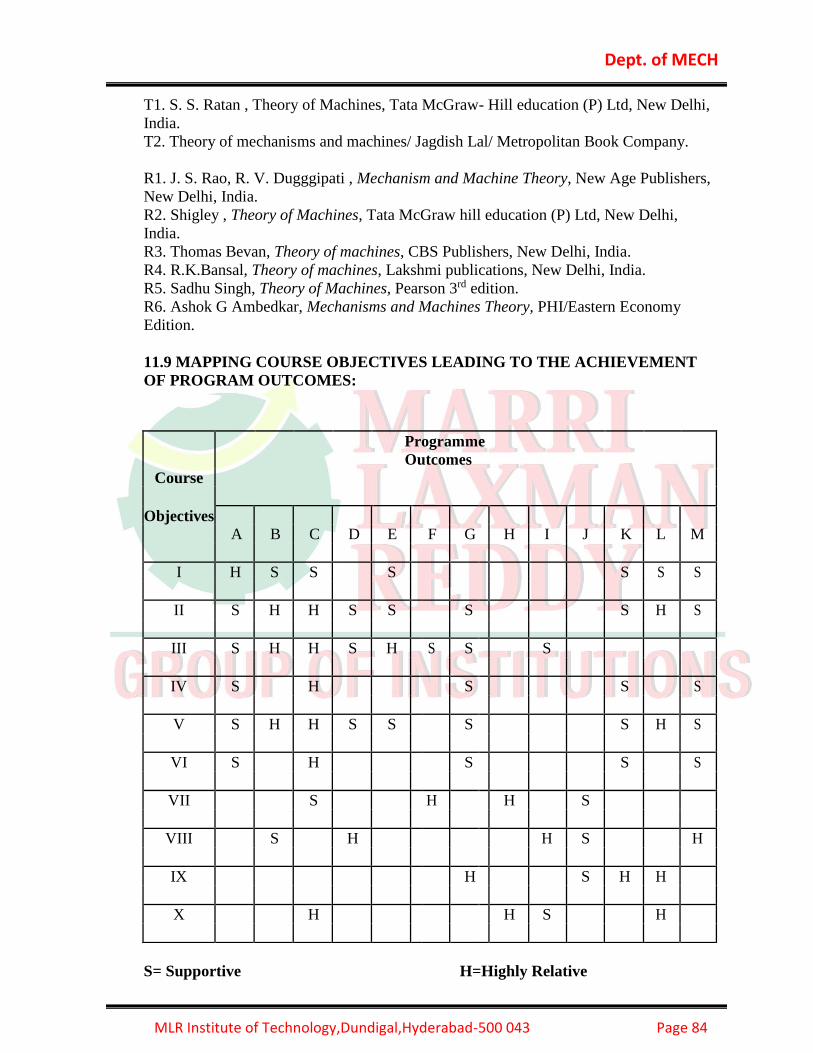
Dept. of MECH
MLR Institute of Technology,Dundigal,Hyderabad-500 043 Page 84
T1. S. S. Ratan , Theory of Machines, Tata McGraw- Hill education (P) Ltd, New Delhi,
India.
T2. Theory of mechanisms and machines/ Jagdish Lal/ Metropolitan Book Company.
R1. J. S. Rao, R. V. Dugggipati , Mechanism and Machine Theory, New Age Publishers,
New Delhi, India.
R2. Shigley , Theory of Machines, Tata McGraw hill education (P) Ltd, New Delhi,
India.
R3. Thomas Bevan, Theory of machines, CBS Publishers, New Delhi, India.
R4. R.K.Bansal, Theory of machines, Lakshmi publications, New Delhi, India.
R5. Sadhu Singh, Theory of Machines, Pearson 3rd edition.
R6. Ashok G Ambedkar, Mechanisms and Machines Theory, PHI/Eastern Economy
Edition.
11.9 MAPPING COURSE OBJECTIVES LEADING TO THE ACHIEVEMENT
OF PROGRAM OUTCOMES:
S= Supportive H=Highly Relative
Course
Programme
Outcomes
Objectives
A B C D E
F G
H I J K L M
I H S S S S S S
II S H H S S S S H S
III S H H S H S S S
IV S H S S S
V S H H S S S S H S
VI S H S S S
VII S H H S
VIII S H H S H
IX H S H H
X H H S H

Dept. of MECH
MLR Institute of Technology,Dundigal,Hyderabad-500 043 Page 85
11.10 MAPPING COURSE OUTCOMES LEADING TO THE ACHIEVEMENT
OF PROGRAM OUTCOMES:
Course
Programme
Outcomes
Outcomes
A B C D E
F G H
I J K L M
a H S S S S S S
b S S S S H S
c H S S S S S
d S S S H S S S
e S H S S S
f S H S S S S
g S S S S S H S
h S S H H S
i H H
j S H S S
k S H
S= Supportive H=Highly Relative

Dept. of MECH
MLR Institute of Technology,Dundigal,Hyderabad-500 043 Page 86
11.11 OBJECTIVE QUESTIONS:
UNIT-I 1. A disc is spinning with an angular velocity ω rad/s about the axis of spin. The couple
applied to the disc causing precession will be [ d ]
where I = Mass moment of inertia of the disc, and
ωp = Angular velocity of precession of the axis of spin.
2. A disc spinning on its axis at 20 rad/s will undergo precession when a torque 100 N-m
is applied about an axis normal to it at an angular speed, if mass moment of inertia of
the disc is the 1 kg-m2 [ b ]
(a) 2 rad/s
(b) 5 rad/s
(c) 10 rad/s
(d) 20 rad/s
3. The engine of an aeroplane rotates in clockwise direction when seen from the tail end
and the aeroplane takes a turn to the left. The effect of the gyroscopic couple on the
aeroplane will be [ a ]
(a) to raise the nose and dip the tail (b) to dip the nose and raise the tail
(c) to raise the nose and tail (d) to dip the nose and tail
4. The air screw of an aeroplane is rotating clockwise when looking from the front. If it
makes a left turn, the gyroscopic effect will [ b ]
(a) tend to depress the nose and raise the tail b) tend to raise the nose and depress the
tail
(c) tilt the aeroplane (d) none of the above
5. The rotor of a ship rotates in clockwise direction when viewed from the stern and the
ship takes a left turn. The effect of the gyroscopic couple acting on it will be [ c ]
(a) to raise the bow and stern (b) to lower the bow and stern
(c) to raise the bow and lower the stern (d) to lower the bow and raise the stern
6. When the pitching of a ship is upward, the effect of gyroscopic couple acting on it will
be [ b ]
(a) to move the ship towards port side (b) to move the ship towards star-board
(c) to raise the bow and lower the stern (d) to raise the stern and lower the bow
7. In an automobile, if the vehicle makes a left turn, the gyroscopic torque [ a ]
(a) increases the forces on the outer wheels (b) decreases the forces on the outer wheels
(c) does not affect the forces on the outer wheels (d) none of the above
8. A motor car moving at a certain speed takes a left turn in a curved path. If the engine
rotates in the same direction as that of wheels, then due to the centrifugal forces [ b ]
(a) the reaction on the inner wheels increases and on the outer wheels decreases

Dept. of MECH
MLR Institute of Technology,Dundigal,Hyderabad-500 043 Page 87
(b) the reaction on the outer wheels increases and on the inner wheels decreases
(c) the reaction on the front wheels increases and on the rear wheels decreases
(d) the reaction on the rear wheels increases and on the front wheels decreases
9. When the crank is at the inner dead centre, in a horizontal reciprocating steam engine,
then the velocity of the piston will be [ a ]
(a) zero (b) minimum (c) maximum (d) None
10. The acceleration of the piston in a reciprocating steam engine is given by [d ]
Where ω = Angular velocity of the crank,
r = Radius of the crank,
θ = Angle turned by the crank from inner dead centre, and
n = Ratio of length of connecting rod to crank radius.
11. A rigid body, under the action of external forces, can be replaced by two masses
placed at a fixed distance apart. The two masses form an equivalent dynamical
system, if [ d ]
(a) The sum of two masses is equal to the total mass of the body
(b) The centre of gravity of the two masses coincides with that of the body
(c) The sum of mass moment of inertia of the masses about their centre of gravity is equal
to the mass moment of inertia of the body
(d) all of the above
12. The essential condition of placing the two masses, so that the system becomes
dynamically equivalent is [ a ]
(a) l1 .l2 = kG2 (b) l1 .l2 = kG
2 (c) l1 = kG (d) l2 = kG
Where l1 and l2 = Distance of two masses from the centre of gravity of the body, and
kG = Radius of gyration of the body.
13. In an engine, the work done by inertia forces in a cycle is [a ]
(a) positive (b) zero (c) negative (d) none of these
14. The resultant forces acting on a body together with reversed effective forces are in
equilibrium, is given by [ a ]
a) D Alemberts Principle b) Newtons Law c) Thermodynamics Law d) None
15. the up and down moment of a Naval Ship is known as [ b ]
a) Steering b) Pitching c) Rolling d)None
16. The fore end of a Naval Ship is termed as [b ]
a) Stern b) Bow c) Port d) Star board
17. The moment of a naval ship with respect to longitudinal axis is known as [c ]
a) Steering b) Pitching c) Rolling d) None

Dept. of MECH
MLR Institute of Technology,Dundigal,Hyderabad-500 043 Page 88
18. The effect of gyroscopic couple in case of rolling of naval ship [c ]
a) Maximum b) Minimum c) No effect d) None
19. Banking of a road surface means [ a ]
a) Inner rail down on outer rail up b) Inner rail up on outer rail down
c) Both rails on same level d) None
20. The pitching of a naval ship is assumed to be [ c ]
a) Linear Motion b) Rotary Motion c) S H M d) None
Unit II
1. The distance between the centers of the adjacent rivets in the same row is called
[A ]
A) pitch B) margin C) row pitch D) diagonal pitch
2. According to I.B.R , safety factor of rivet joint should not be less than ___.[ D ]
(A)3 B) 2 C)5 D) 4
3. The angle of inclination of the plane, at which the body begins to move down the
plane, is called [ a ]
(a) angle of friction (b) angle of repose (c) angle of projection d) None
4. In a screw jack, the effort required to lift the load W is given by [ b ]
(a) P = W tan (α – φ) (b) P = W tan (α + φ)
(c) P = W cos (α – φ) (d) P = W cos (α + φ)
where α = Helix angle, and
φ = Angle of friction.
5. The efficiency of a screw jack is given by [ b ]
6. The radius of a friction circle for a shaft of radius r rotating inside a bearing is [ a ]
(a) r sin φ (b) r cos φ (c) r tan φ (d) r cot φ
7. The efficiency of a screw jack is maximum, when [ b ]
8. The maximum efficiency of a screw jack is [ a]
9. The frictional torque transmitted in a flat pivot bearing, considering uniform pressure,
is [ b]

Dept. of MECH
MLR Institute of Technology,Dundigal,Hyderabad-500 043 Page 89
where μ = Coefficient of friction,
W = Load over the bearing, and
R = Radius of the bearing surface.
10. The frictional torque transmitted in a conical pivot bearing, considering uniform
wear, is [ a ]
where R = Radius of the shaft, and
α = Semi-angle of the cone.
11. The frictional torque transmitted by a disc or plate clutch is same as that of [ b ]
(a) flat pivot bearing (b) flat collar bearing
(c) conical pivot bearing (d) trapezoidal pivot bearing
12. The frictional torque transmitted by a cone clutch is same as that of [ d ]
(a) flat pivot bearing (b) flat collar bearing
(c) conical pivot bearing (d) trapezoidal pivot bearing
13. The brakes commonly used in railway trains is [ a ]
a) shoe brake (b) band brake
c) band and block brake (d) internal expanding brake
14. The brake commonly used in motor cars is [ d]
(a )shoe brake (b) band brake
(c) band and block brake (d) internal expanding brake
15. When brakes are applied to all the four wheels of a moving car, the distance travelled
by
the car before it is brought to rest, will be [ b ]
(a) maximum (b) minimum c) Zero d) None
16. Which of the following is an absorption type dynamometer? [ a ]
a) prony brake dynamometer (b) torsion dynamometer
c) epicyclic-train dynamometer (d) None
17. A band brake having band-width of 80mm, drum diameter of 250mm, coefficient of
friction of 0.25 and angle of wrap of 270 degrees is required to exert a friction torque of
1000N-m. The maximum tension (in kN) developed in the band is [C ]
(A) 1.88 (B) 3.56 (C) 6.12 (D) 11.56 GATE 2010
18. Automatically engaged and disengaged clutch is known as [ c ]
a) Disc clutch b) Cone Clutch c) Centrifugal Clutch d) None

Dept. of MECH
MLR Institute of Technology,Dundigal,Hyderabad-500 043 Page 90
19. The brake applied on brake drum in radial direction is known as [ a ]
a) Radial brake b) Axial brake c) Hydrodynamic brake d) None
A 1 kg block is resting on a surface with coefficient of friction μ = 0.1. A force of 0.8N is
applied to the block as shown in figure. The friction force is [ B]
(A) 0 (B) 0.8N (C) 0.98N (D) 1.2N
GATE 2011
20. Which of the following is a transmission type dynamometer? [ c ]
a)Prony brake dynamometer (b) rope brake dynamometer
c)epicyclic-train dynamometer (d) None
Unit III
13. A flywheel connected to a punching machine has to supply energy of 400 Nm while
running at a mean angular speed of 20 radians/s. If the total fluctuation of speed is not to
exceed ±2%, the mass moment of inertia of the flywheel in 2 kg − m is
[A]
14. (A) 25 (B) 50 (C) 100 (D) 125
15.
16.
17. In a turning moment diagram, the variations of energy above and below the mean
resisting torque line is called [ a ]
18. a) fluctuation of energy b) maximum fluctuation of energy
19. c) coefficient of fluctuation of energy c)none of the above
20.
21. The ratio of the maximum fluctuation of speed to the mean speed is called [ c ]
22. a) fluctuation of speed (b) maximum fluctuation of speed
23. c) coefficient of fluctuation of speed (d) none of these
24. CS = Coefficient of fluctuation of speed, and
25. ω= Mean angular speed = ( ω1 + ω2 )/2
26.
27. The maximum fluctuation of energy is the [ b ]
28. a) sum of maximum and minimum energies
29. b) difference between the maximum and minimum energies
30. c) ratio of the maximum energy and minimum energy
31. d) ratio of the mean resisting torque to the work done per cycle
32.
33. The maximum fluctuation of energy in a flywheel is equal to [ d ]
34. (a) I .ω (ω1 − ω2 ) (b) 2 I .ω2 .CS (c) 2E.CS (d) all of these

Dept. of MECH
MLR Institute of Technology,Dundigal,Hyderabad-500 043 Page 91
36. The ratio of the maximum fluctuation of energy to the, ......... is called coefficient of
fluctuation of energy. [ b ]
37. (a) minimum fluctuation of energy (b) work done per cycle
38. where I = Mass moment of inertia of the flywheel,
39. E = Mean kinetic energy of the flywheel,
40.
41. The height of a Watt’s governor (in metres) in equal to [ c ]
42. (a) 8.95/N2 (b) 89.5/N2 c) 895/N2 (d) 8950/N2
43. where N = Speed of the arm and ball about the spindle axis
44.
45.
46. When the sleeve of a Porter governor moves upwards, the governor speed [ a ]
47. a) increases (b) decreases (c) remains unaffected d)None
48.
49. A Hartnell governor is a [ b ]
50. (a) pendulum type governor (b) spring loaded governor
51. (c) dead weight governor (d) inertia governor
52.
53. Which of the following governor is used to drive a gramophone ? [ c ]
54. (a) Watt governor (b) Porter governor
55. (c) Pickering governor (d) Hartnell governor
56.
57. Which of the following is a spring controlled governor? [ d ]
58. (a) Hartnell (b) Hartung (c) Pickering (d) all of these
59.
60. For two governors A and B, the lift of sleeve of governor A is more than that of
governor B, for a given fractional change in speed. It indicates that [ a ]
61. a) governor A is more sensitive than governor B
62. b) governor B is more sensitive than governor A
63. c) both governors A and B are equally sensitive
64. d) none of the above
65.
66. The sensitiveness of a governor is given by [ b ]
67. (a)ω mean/(ω2 −ω1) (b) (ω2 −ω1)/ ωmean (c) (ω2 −ω1)/ 2ωmean (d)none where
ω1 and ω2 = Minimum and maximum angular speed, and
68. ωmean = Mean angular speed.
69.
70. In a Hartnell governor, if a spring of greater stiffness is used, then the governor will
[ b ]
71. (a) more sensitive (b) less sensitive (c) isochronous d) None
72.
73. A governor is said to be hunting, if the speed of the engine [ d ]
74. a) remains constant at the mean speed b) is above the mean speed
75. c) is below the mean speed
76. d) fluctuates continuously above and below the mean speed.

Dept. of MECH
MLR Institute of Technology,Dundigal,Hyderabad-500 043 Page 92
78. A hunting governor is [ c ]
79. a) more stable (b) less sensitive (c) more sensitive (d) none
80.
81. Isochronism in a governor is desirable when [ b ]
82. a) the engine operates at low speeds b) the engine operates at high speeds
83. c) the engine operates at variable speeds d) one speed is desired under one load
84.
85. When the relation between the controlling force (Fc ) and radius of rotation (r) for a
spring controlled governor is Fc = a.r + b, then the governor will be [b ]
86. a) stable (b) unstable c) isochronous d) None
87.
88. A governor which canot be ischronous is [ a ]
89. a) porter b) Hartnell c) Watt d) Hartung
90.
91. When the relation between the controlling force (Fc ) and radius of rotation (r) for a
spring controlled governor is Fc = a.r, then the governor will be [ c ]
92. a) stable (b) unstable c) isochronous d) None
Unit IV
1. The balancing of rotating and reciprocating parts of an engine is necessary when it runs
at
[ c ]
(a) slow speed (b) medium speed (c) high speed
2. A disturbing mass m1 attached to a rotating shaft may be balanced by a single mass m2
attached in the same plane of rotation as that of m1 such that [ b ]
(a) m1.r2 = m2.r1 (b) m1.r1 = m2.r2 (c) m1. m2 = r1.r2
3. For static balancing of a shaft, [ a ]
(a) the net dynamic force acting on the shaft is equal to zero
(b) the net couple due to the dynamic forces acting on the shaft is equal to zero
(c) both (a) and (b)
(d) none of the above
4. For dynamic balancing of a shaft, [ c ]
(a) the net dynamic force acting on the shaft is equal to zero
(b) the net couple due to dynamic forces acting on the shaft is equal to zero
(c) both (a) and (b)
(d) none of the above
5. In order to have a complete balance of the several revolving masses in different planes
[ c]
(a) the resultant force must be zero
(b) the resultant couple must be zero
(c) both the resultant force and couple must be zero
(d) none of the above

Dept. of MECH
MLR Institute of Technology,Dundigal,Hyderabad-500 043 Page 93
6.The primary unbalanced force is maximum when the angle of inclination of the crank
with the line of stroke is [ c ]
(a) 0° (b) 90° (c) 180° (d) 360°
7. The partial balancing means [ b ]
(a) balancing partially the revolving masses (b) balancing partially the reciprocating
masses
(c) best balancing of engines (d) all of the above
8.In order to facilitate the starting of locomotive in any position, the cranks of a
locomotive, with two cylinders, are placed at . . . . . . to each other. [ b ]
a) 45° (b) 90° (c) 120° (d) 180°
9.In a locomotive, the ratio of the connecting rod length to the crank radius is kept very
large in order to [ b ]
(a) minimise the effect of primary forces (b) minimise the effect of secondary forces
(c) have perfect balancing (d) start the locomotive quickly
10.The swaying couple is maximum or minimum when the angle of inclination of the
crank to the line of stroke ( θ ) is equal to [ b ]
(a) 45° and 135° (b) 90° and 135°
(c) 135° and 225° (d) 45° and 225°
11.The tractive force is maximum or minimum when the angle of inclination of the crank
to the line of stroke ( θ ) is equal to [ d ]
(a) 90° and 225° (b) 135° and 180° (c) 180° and 225° (d) 135° and 315°
12. The swaying couple is due to the [ a ]
(a) primary unbalanced force (b) secondary unbalanced force
(c) two cylinders of locomotive (d) partial balancing
13.In a locomotive, the maximum magnitude of the unbalanced force along the
perpendicular to the line of stroke, is known as [ c ]
(a ) tractive force (b) swaying couple (c) hammer blow (d) none of these
14.The effect of hammer blow in a locomotive can be reduced by [ d]
(a) decreasing the speed (b) using two or three pairs of wheels coupled together
(c) balancing whole of the reciprocating parts (d) both (a) and (b)
15.Multi-cylinder engines are desirable because [c ]
(a) only balancing problems are reduced (b) only flywheel size is reduced
(c) both (a) and (b) (d) none of these
16.When the primary direct crank of a reciprocating engine makes an angle θ with the
line of stroke, then the secondary direct crank will make an angle of . . . . . with the line
of stroke.
[ c ]
(a) θ /2 (b) θ (c) 2 θ (d) 4 θ

Dept. of MECH
MLR Institute of Technology,Dundigal,Hyderabad-500 043 Page 94
17. Secondary forces in reciprocating mass on engine frame are [ a ]
(a) of same frequency as of primary forces (b) twice the frequency as of primary forces
(c) four times the frequency as of primary forces (d) none of the above
18.The secondary unbalanced force produced by the reciprocating parts of a certain
cylinder of a given engine with crank radius r and connecting rod length l can be
considered as equal to primary unbalanced force produced by the same weight having
[ a ]
(a) an equivalent crank radius r2/4l and rotating at twice the speed of the engine
(b) r2/4l as equivalent crank radius and rotating at engine speed
(c) equivalent crank length of r2/4l and rotating at engine speed
(d) none of the above
19. Which of the following statement is correct? [c ]
(a) In any engine, 100% of the reciprocating masses can be balanced dynamically
(b) In the case of balancing of multicylinder engine, the value of secondary force is
higher than the value of the primary force
(c) In the case of balancing of multimass rotating systems, dynamic balancing can be
directly
started without static balancing done to the system
(d) none of the above.
20.Inradial engine , since the plane of rotation of the various cranks is same there is no
[ a ]
a) unbalanced primary and secondary forces b) unbalanced primary
c) unbalanced secondary forces d) None
Unit V
1. When there is a reduction in amplitude over every cycle of vibration, then the body is
said to have [ c ]
(a) free vibration (b) forced vibration (c) damped vibration d) None
2. Longitudinal vibrations are said to occur when the particles of a body moves [b]
a) perpendicular to its axis (b) parallel to its axis (c) in a circle about its axis
3. When a body is subjected to transverse vibrations, the stress induced in a body will be
[ b]
(a) shear stress (b) tensile stress (c) compressive stress
4. The natural frequency (in Hz) of free longitudinal vibrations is equal to [ d ]
(a) 1/2π s/m (b 1/2π δ/g (c ) 0.4985/δ d) All of the above
where m = Mass of the body in kg,
s = Stiffness of the body in N/m, and
δ = Static deflection of the body in metre
5.The factor which affects the critical speed of a shaft is [ d ]
(a) diameter of the disc (b) span of the shaft
(c) eccentricity (d) all of these

Dept. of MECH
MLR Institute of Technology,Dundigal,Hyderabad-500 043 Page 95
5. The equation of motion for a vibrating system with viscous damping is d x2/ dt2 +
c/mX dx/ dt + s/mXx = 0 If the roots of this equation are real, then the system will be
[ a ]
(a) over damped (b) under damped (c) critically damped
6. In under damped vibrating system, if x1 and x2 are the successive values of the
amplitude on the same side of the mean position, then the logarithmic decrement is equal
to [ b ]
(a) x1/x2 (b) log (x1/x2) (c) loge (x1/x2) (d) log (x1.x2)
7. The ratio of the maximum displacement of the forced vibration to the deflection due to
the static force, is known as [ d ]
(a) damping factor (b) damping coefficient
(c) logarithmic decrement (d) magnification factor
8. In vibration isolation system, if ω/ωn is less than 2 , then for all values of the damping
factor, the transmissibility will be [ c ]
(a) less than unity (b) equal to unity (c) greater than unity (d) zero
where ω = Circular frequency of the system in rad/s, and
ωn = Natural circular frequency of vibration of the system in rad/s.
10. In vibration isolation system, if ω/ωn >1, then the phase difference between the
transmitted force and the disturbing force is [ c ]
(a) 0° (b) 90° (c) 180° (d) 270°
9. The ratio of maximum displacement of the forced vibrations to the static deflection is
called [ d ]
(a) Logarithmic decrement (b) Damping co-efficient
(c) critical damping co-efficient (d)Magnification factor
10. In SHM the product of periodic time ad the frequecy if equal to [ d]
a) Zero b) Unity c) π d) π/2
11. If the damping factor for a vibrating system is unity, the system is [a]
a) Critical damping b) Under damping c) Over damping d) none
12. If the damping factor for a vibrating system is more than unity, the system is [ c ]
a) Critical damping b) Under damping c) Over damping d) none
13. At the nodal point in a shaft the amplitude of torsional vibration is [a ]
a) Zero b) minimum c) maximum d) None
14. A shaft carrying two rotors as its ends will have [ b ]
a) One node b) Two node c) Three node d) None
15. In vibration isolation, which one of the following statements is NOT correct
regarding Transmissibility (T)? [ B ]
(A) T is nearly unity at small excitation frequencies

Dept. of MECH
MLR Institute of Technology,Dundigal,Hyderabad-500 043 Page 96
(B) T can be always reduced by using higher damping at any excitation frequency
(C) T is unity at the frequency ratio of 2
(D) T is infinity at resonance for undamped systems GATE-2014
16. Figure shows a single degree of freedom system. The system consists of a massless
rigid bar OP hinged at O and a mass m at end P. The natural frequency of vibration of
the system I [A ]
18. Consider a single degree-of-freedom system with viscous damping excited by a
harmonic force. At resonance, the phase angle (in degree) of the displacement with
respect to the exciting force is [ C ]
(A) 0 (B) 45 (C) 90 (D) 135 GATE 2014
19. Critical damping is the [ B ]
(A) Largest amount of damping for which no oscillation occurs in free vibration
(B) Smallest amount of damping for which no oscillation occurs in free vibration
(C) Largest amount of damping for which the motion is simple harmonic in free vibration
(D) Smallest amount of damping for which the motion is simple harmonic in free
vibration GATE 2015
20.A single degree of freedom system having mass 1 kg and stiffness 10kN/m initially at
rest is subjected to an impulse force of magnitude 5 kN for 10-4 seconds. The amplitude
in mm of the resulting free vibration is [ c]
(A) 0.5 (B) 1.0 (C) 5.0 (D)10.0 GATE 2013

Dept. of MECH
MLR Institute of Technology,Dundigal,Hyderabad-500 043 Page 97
11.12 TUTORIAL QUESTIONS:
Sl.No. Questions
Blooms
Taxonomy
Level
Course
Outcome
UNIT-I
Tutorials
Short Answer Questions
1 1. Define what is precesional angular motion Knowledge a
2 2. Discuss about right hand screw rule Knowledge b
3 3. Derive a formula for gyroscopic couple. Analysis e
4 4. Write a short note on gyroscope. comprehension c
5 5. Define the pitching of a naval ship. comprehension a
6 When pitching up ward what is the effect of reactive
gyroscopic couple Knowledge a
7 6. What is the effect of reactive gyroscopic couple when
a naval ship is rolling Knowledge a
8 Describe the gyroscopic effect on an aeroplane Analysis a
9
7. What are the conditions for a body to be in
equilibrium under the action of two forces and
torque
Analysis a
10 8. State and explain the D’Alembert’s Principle. Knowledge b
Sl.No. Questions
Blooms
Taxonomy
Level
Course
Outcome
UNIT-I
Tutorials
Long Answer Questions
1
The turbine rotor of a ship has a mass of 20 tones & a
radius of gyration of 0.75m.Its speed is 2000 rpm.the
ship pitches 6degrees above & below the horizontal
position. One complete oscillation takes 18 sec & the
motion is simple harmonic. Determine
(i)The maximum couple tending to shear the holding
down bolts of the turbine.
(ii)The maximum angular acceleration of the ship
during pitching &
(iii)The direction in which the bow will tend to turn
while rising, if the rotation the rotor is clock wise
when looking from rear.
Apply b
2
A car weighs 20KN. It has a wheel base of 2m, Track
width 1m & Height of C.G. 300 mm above the
ground level & lies midway between the front & rear
axle. The engine flywheel rotates at 3000 rpm
Apply b

Dept. of MECH
MLR Institute of Technology,Dundigal,Hyderabad-500 043 Page 98
clockwise when viewed from the front. The moment of
inertia of the fly wheel is 4kg-m² & MOI of each
wheel is 3 kg-m², find the reactions between the
wheels & the ground when car takes the curve of 15m
radius towards right at 30 km/hr, taking into
consideration the gyroscopic & the centrifugal effects.
Each wheel radius is 400mm
3
The rotor of the turbine of a yacht makes 1200 rpm
clockwise when viewed from the stern. The rotor has a
mass of 750 kg, and its radius of gyration is 250 mm.
Find the maximum gyroscopic couple transmitted to
the hull (body of the yacht), when the yacht pitches
with maximum angular velocity of 1 rad/s.
Analysis b
4
An aeroplane makes a complete half circle of 50
meters radius, towards left, when flying at 200 kmph.
The rotary engine and the propeller of the plane has a
mass of 400 kg. and a radius of gyration of 0.3 m. The
engine rotates at 2400 r.p.m. clockwise when viewed
from the rear. Find the gyroscopic couple on the
aircraft and state its effect on it.
Analysis a
5
A four wheeled motor car of mass 2000 kg has a wheel
base 2.5 m, track width 1.5 m and height of center of
gravity 500 mm above the ground level and lies at 1
meter from the front axle. Each wheel has an an
effective diameter of 0.8 m and a moment of inertia of
0.8 kg-m2. The drive shaft, Engine flywheel and
transmission are rotating at 4 times the speed of road
wheel, in a clockwise direction when viewed from the
front, and is equivalent to a mass of 75 kg having a
radius of gyration of 100 mm. If the car is taking a
right turn of 60 m radius at 60 km/h, find the load on
each wheel.
Analysis a
7
In a slider crank mechanism, the lengths of the crank
and the connecting rod are 480 mm and 1.6 m
respectively. It has an eccentricity of 100 mm.
Assuming a velocity of 20 rad/sec of the crank OA.
Calculate the following at an interval of 30 degrees.
i). Velocity and the acceleration of the slider
ii). Angular velocity and angular acceleration of the
connecting rod.
Apply b
8
In a Four-link mechanism, the dimensions of the links
are: AB=20 mm, BC= 66mm, CD= 56 mm, and AD =
80 mm. AD is the fixed link. The crank rotates at
uniform angular velocity of 10.5 rad/sec in the
counter-clockwise direction. Determine the angular
displacements, angular velocities angular accelarations
of the output link DC and the coupler BC for a
Analysis a

Dept. of MECH
MLR Institute of Technology,Dundigal,Hyderabad-500 043 Page 99
complete revolution of the crank at an interval of 40
degrees.
9
Determine the required input torque on the crank of a
slider-crank mechanism for the static equilibrium
when the applied piston load is 1500N. the lengths of
the crank and the connecting rod are 40mm and 100
mm respectively, and the crank has turned through 450
from the inner dead centre.
Analysis a
10
Synthesize a 4 – bar mechanism to generate a function
y=log x for 1 ≤ x ≤ 2. The range of the output crank
may be chosen as 900 while that of input crank be 600.
Assume three precession points which are to be
obtained from Chebyshev spacings.
Apply a
Sl.No.
Questions Blooms
Taxonomy
Level
Course
Outcome
UNIT-II
Tutorials
Short Answer Questions
1 Define the phenomena of friction Analysis b
2 Briefly explain about screw jack comprehension a
3 Discuss Briefly about over hauling and self locking of
screw comprehension b
4 Define the terms of angle of repose Analysis e
5 Give a brief account of friction between lubricated
surfaces Knowledge b
6 what ifs friction circle comprehension a
7 what are the various types of mechanical brakes Analysis b
8 Which type of brakes used in locomotive Knowledge e
9 Explain the function of Absorption type Dynamometer Knowledge a
10 what are the varies types of transmission
Dynamometers Knowledge a
Sl.No.
Questions Blooms
Taxonomy
Level
Course
Outcome
UNIT-II
Tutorials
Long Answer Questions
1
The lead screw of the lathe has acme threads of 50
mm outside diameter and 10 mm pitch. The included
angle of thread is 29 degrees. It drives a tool carriage
and exerts a pressure of 2500N. A collar bearing with
outside diameter 100mm and inside diameter 50mm is
Analysis b
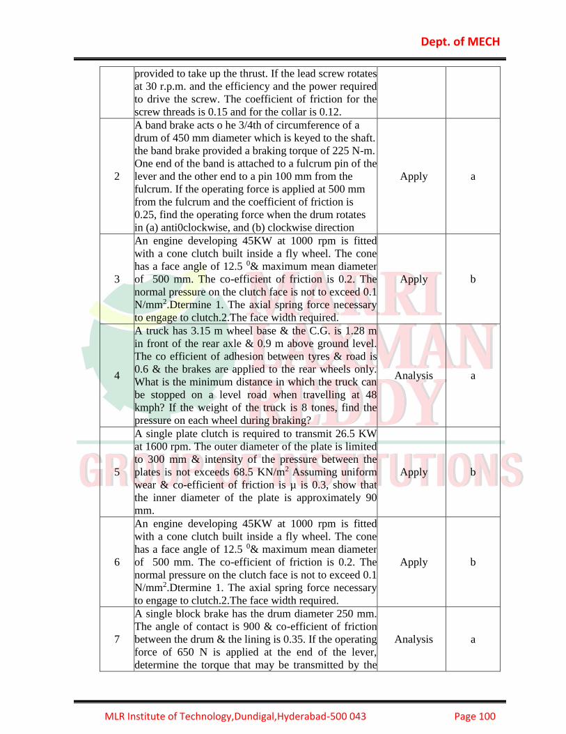
Dept. of MECH
MLR Institute of Technology,Dundigal,Hyderabad-500 043 Page 100
provided to take up the thrust. If the lead screw rotates
at 30 r.p.m. and the efficiency and the power required
to drive the screw. The coefficient of friction for the
screw threads is 0.15 and for the collar is 0.12.
2
A band brake acts o he 3/4th of circumference of a
drum of 450 mm diameter which is keyed to the shaft.
the band brake provided a braking torque of 225 N-m.
One end of the band is attached to a fulcrum pin of the
lever and the other end to a pin 100 mm from the
fulcrum. If the operating force is applied at 500 mm
from the fulcrum and the coefficient of friction is
0.25, find the operating force when the drum rotates
in (a) anti0clockwise, and (b) clockwise direction
Apply a
3
An engine developing 45KW at 1000 rpm is fitted
with a cone clutch built inside a fly wheel. The cone
has a face angle of 12.5 0& maximum mean diameter
of 500 mm. The co-efficient of friction is 0.2. The
normal pressure on the clutch face is not to exceed 0.1
N/mm2.Dtermine 1. The axial spring force necessary
to engage to clutch.2.The face width required.
Apply b
4
A truck has 3.15 m wheel base & the C.G. is 1.28 m
in front of the rear axle & 0.9 m above ground level.
The co efficient of adhesion between tyres & road is
0.6 & the brakes are applied to the rear wheels only.
What is the minimum distance in which the truck can
be stopped on a level road when travelling at 48
kmph? If the weight of the truck is 8 tones, find the
pressure on each wheel during braking?
Analysis a
5
A single plate clutch is required to transmit 26.5 KW
at 1600 rpm. The outer diameter of the plate is limited
to 300 mm & intensity of the pressure between the
plates is not exceeds 68.5 KN/m2 Assuming uniform
wear & co-efficient of friction is µ is 0.3, show that
the inner diameter of the plate is approximately 90
mm.
Apply b
6
An engine developing 45KW at 1000 rpm is fitted
with a cone clutch built inside a fly wheel. The cone
has a face angle of 12.5 0& maximum mean diameter
of 500 mm. The co-efficient of friction is 0.2. The
normal pressure on the clutch face is not to exceed 0.1
N/mm2.Dtermine 1. The axial spring force necessary
to engage to clutch.2.The face width required.
Apply b
7
A single block brake has the drum diameter 250 mm.
The angle of contact is 900 & co-efficient of friction
between the drum & the lining is 0.35. If the operating
force of 650 N is applied at the end of the lever,
determine the torque that may be transmitted by the
Analysis a

Dept. of MECH
MLR Institute of Technology,Dundigal,Hyderabad-500 043 Page 101
block brake?
8
A truck has 3.15 m wheel base & the C.G. is 1.28 m
in front of the rear axle & 0.9 m above ground level.
The co efficient of adhesion between tyres & road is
0.6 & the brakes are applied to the rear wheels only.
What is the minimum distance in which the truck can
be stopped on a level road when traveling at 48
kmph? If the weight of the truck is 8 tones, find the
pressure on each wheel during braking?
Apply b
9
A bicycle & rider of mass 100 kg are traveling at the
rate of 16 kmph on a level road. A brake is applied to
the rear wheel which is 0.9 m in diameter & this is the
only resistance acting. How far will the bicycle travel
& how many turns will it make before it comes to
rest. The pressure applied on the brake is 100 N & the
co-efficient of friction is 0.2
Apply b
10
A car is moving on a level road at a speed of 36
kmph. Its C.G. lies at a distance of 0.6 m from the
ground level. The wheel base is 2.4 m & the
distance of C.G from the rear wheels is 0.9 m. Find
the distance traveled by the car before coming to
rest when brakes are applied, 1.To the rear wheels.
2. To the front wheels. 3. To all the four wheels.
The co-efficient of friction between the tyres & the
road surface is 0.45.
Apply b
Sl.No. Questions
Blooms
Taxonomy
Level
Course
Outcome
UNIT-III
Tutorials
Short Answer Questions
1 Define coefficient of fluctuation of speed Knowledge b
2 What is the function of flywheel Knowledge e
3 What is the formula for max fluctuation of energy in a
flywheel Analysis b
4 Define coefficient of fluctuation of Energy comprehension a
5 Discuss the turning moment diagram comprehension b
6 What is the Coefficient of steadiness Knowledge e
7 Explain precisely the uses of turning moment diagram
of a 4 stroke cycle internal combustion engine? Knowledge b
8 What is the function of a fly wheel? How does it differ
from that of a governor? Analysis e
9 What is the function of fly wheel in punching press Analysis b
10 Draw the turning moment diagram of a single cylinder
double acting steam engine? Knowledge a

Dept. of MECH
MLR Institute of Technology,Dundigal,Hyderabad-500 043 Page 102
Sl.No. Questions
Blooms
Taxonomy
Level
Course
Outcome
UNIT-III
Tutorials
Long Answer Questions
1
The turning moment diagram of a petrol engine is
drawn to the following scales: Turning moment, 1mm =
5 N-m; crank angle, 1 mm = 10. The turning moment
diagram repeats itself at every half revolution of the
engine & the areas above & below the mean turning
moment line taken in order are 295, 685,40, 340,
960,270 mm2 . The rotating parts are equivalent to a
mass of 36 kg at the radius of gyration of 150 mm.
Determine the co efficient of fluctuation of speed when
the engine runs at 1800 rpm.
Apply b
2
The turning moment diagram of a multi cylinder engine
is drawn to the following scales: Turning moment, 1mm
= 600 N-m vertically;& 1mm = 30 horizontally, The
intercepted areas between the output torque curve & the
mean resistance line, taken in order from one end, are as
follows : +52 -124, +92, -140, + 85, -72 & +107 mm2.
When the engine is running at a speed of 600 rpm. If the
total fluctuation of speed is not to exceed± 1.5 % of the
mean, find the necessary mass of the flywheel of radius
0.5 m.
Apply e
3
The turning moment diagram of a petrol engine is
drawn to the following scales: Turning moment, 1mm =
6 N-m; crank angle, 1 mm = 20. The turning moment
diagram repeats itself at every half revolution of the
engine & the areas above & below the mean turning
moment line taken in order are 290, 680,45, 345,
965,275 mm2 . The rotating parts are equivalent to a
mass of 36 kg at the radius of gyration of 155 mm.
Determine the co efficient of fluctuation of speed when
the engine runs at 1850 rpm.
Apply b
4
The turning moment diagram of a multi cylinder engine
is drawn to the following scales: Turning moment, 1mm
= 500 N-m vertically;& 1mm = 35 horizontally, The
intercepted areas between the output torque curve & the
mean resistance line, taken in order from one end, are as
follows : +53,-125,+93, -142, + 86, -73 & +108 mm2.
When the engine is running at a speed of 600 rpm. If the
total fluctuation of speed is not to exceed± 1.6 % of the
mean, find the necessary mass of the flywheel of radius
0.6 m.
Apply a

Dept. of MECH
MLR Institute of Technology,Dundigal,Hyderabad-500 043 Page 103
5
The mass of the flywheel of an engine is 6.5 tones & the
radius of gyration is 1.8 m. It is found from the turning
moment diagram that the fluctuation of energy is 56
KN-m. If the mean speed of the engine is 120 rpm, find
the maximum & minimum speeds
Apply b
6
The equation of the turning moment curve of a three
crank engine is (5000 + 1500 sin 3θ ) N-m, where θ is
the crank angle in radians. the moment of inertia of the
flywheel is 1000kg-m2 and the mean speed is 300r.p.m
calculate:1.power of the engine, and 2.the maximum
fluctuation of the speed of the flywheel in percentage
when (i) the resisting torque is constant, and(ii)the
resisting torque is (500+600 sin θ)N-m.
Apply b
7
The turning moment diagram of a petrol engine is
drawn to the following scales: Turning moment, 1mm =
5 N-m; crank angle, 1 mm = 10. The turning moment
diagram repeats itself at every half revolution of the
engine & the areas above & below the mean turning
moment line taken in order are 295, 685,40, 340,
960,270 mm2 . The rotating parts are equivalent to a
mass of 36 kg at the radius of gyration of 150 mm.
Determine the co efficient of fluctuation of speed when
the engine runs at 1800 rpm.
Apply b
8
In a spring loaded governor of the Hartnell type, the
mass of each ball is 1kg, length of vertical arm of the
bell crank lever is 100 mm and that of the horizontal
arm is 50 mm. The distance of fulcrum of each bell
crank lever is 80 mm from the axis of rotation of the
governor. The extreme radii of rotation of the balls are
75 mm and 112.5mm. The maximum equilibrium speed
is 5 per cent greater than the minimum equilibrium
speed which is 360 r.p.m. Find, neglecting obliquity of
arms, initial compression of the spring and equilibrium
speed corresponding to the radius of rotation of 100
mm.
Analysis e
9
A hart Nell governor having a central sleeve spring and
two right-angled bell crank levers moves between 290
r.p.m. and 310 r.p.m. for sleeve lift of 15 mm. The
sleeve arms and ball arms are 80 mm and 120 mm
respectively. The leavers are pivoted at 120 mm from
the governor axis and mass of each ball is 2.5 k. the ball
arms are parallel to the governor axis at the lowest
equilibrium speed. Determine: 1. loads on the spring at
lowest and the highest equilibrium speeds, and 2.
stiffness of the spring.
Analysis b
10
The following particulars refer to a Wilson-Hart Nell
governor: Mass of each ball = 125 mm; maximum
radius =175 mm ; minimum speed = 240 r.p.m ;
Apply a

Dept. of MECH
MLR Institute of Technology,Dundigal,Hyderabad-500 043 Page 104
maximum speed = 250 r.p.m ; length of the ball arm of
each bell crank lever=150 mm; length of the sleeve arm
bell crank lever = 100 mm; combined stiffness of the
two ball springs = 0.2 kN/m. Find the equivalent
stiffness of the auxiliary spring referred to the sleeve.
Sl.No. Questions
Blooms
Taxonomy
Level
Course
Outcome
UNIT-IV
Tutorials
Short Answer Questions
1 Why is balancing of rotating parts necessary for high
speed engines ? Analysis b
2
Explain clearly the terms ‘static balancing’ and
‘dynamic balancing’. State the necessary conditions to
achieve them.
comprehension e
3 Discuss how a single revolving mass is balanced by
two masses revolving in different planes. comprehension b
4 Explain the method of balancing of different masses
revolving in the same plane. Analysis a
5 How the different masses rotating in different planes
are balanced ? Knowledge b
6 Write a short note on primary and secondary balancing. comprehension b
7 Explain why only a part of the unbalanced force due to
reciprocating masses is balanced by revolving mass. Analysis e
8 What are in-line engines ? How are they balanced ? It
is possible to balance them completely ? Knowledge b
9 Explain the ‘direct and reverse crank’ method for
determining unbalanced forces in radial engines. Knowledge a
10 Discuss the balancing of V-engines Knowledge b

Dept. of MECH
MLR Institute of Technology,Dundigal,Hyderabad-500 043 Page 105
Sl.No. Questions
Blooms
Taxonomy
Level
Course
Outcome
UNIT-IV
Tutorials
Long Answer Questions
1
Four masses m1 ,m2, m3 and m4 are 200 kg , 300 kg , 240
kg , and 260 kg respectively. The corresponding radii of
rotation are 0.2m , 0.15m, 0.25m and 0.3m respectively
and the angles between successive masses are 45 degree,
35 degree and 135 degree. Find the postion and magnitude
of the balance mass required, if its radius of the rotation is
0.2m.
Analysis b
2
A,B,C and D are four masses carried by a rotating shaft at
radii 100, 125, 200 and 150 mm respectively. The planes
in which the masses revolve are spaced 600 mm apart and
the mass of B,C and D are 10 kg, 5 kg and 4 kg
respectively. Find the required mass a and the relative
angular settings of the four masses so that the shaft shall
be in complete balance.
Apply e
3
A shaft has three eccentrics, each 75 mm diameter and 25
mm thick, machined in one piece with the shaft. The
central planes of the eccentric are 60 mm apart. The
distance of the centers from the axis of rotation are 12
mm, 18 mm and 12 mm and their angular positions are
120 degrees apart. The density of metal is 7000 kg /m3.
Find the amount of out-of-balance force and couple at 600
r.p.m. If the shaft is balanced by adding two masses at a
radius 75 mm at distances of 100 mm from the central
plane of the middle eccentric, find the amount of masses
and their angular positions.
Apply b
4
A shaft carrier five masses A,B,C,D and E which revolves
at the same radius in planes which are equidistant from
one another. The magnitude of the masses in planes A, C
and D are 50 kg, 40 kg and 80 kg respectively. The angle
between A and C and that between C and D is 135
degrees. Determine the magnitude the masses in planes
Band E and their position to put the shaft in complete
rotating balance.
Analysis a
5
A,B,C and D are four masses carried by a rotating shaft at
radii 100 mm, 150 mm ,150mm and 200mm respectively.
The planes in which the masses rotate are spaced at
500mm apart and the magnitude of the masses B,C and D
are 9kg,5 kg and 4 kg respectively. Find the required mass
A and the relative angular settings for the four masses so
that the shaft shall in complete balance.
Apply b

Dept. of MECH
MLR Institute of Technology,Dundigal,Hyderabad-500 043 Page 106
6
In an in-line six cylinder engine a working on two stroke
cycle, the cylinder center lines are spaced at 600 mm. in
end view, the crank shaft 60 degree apart and in the order
1-4-5-2-3-6. The stroke of each piston is 400 mm and the
connecting rod length is 1 meter. The mass of the
reciprocating parts is 200 kg per cylinder and that of
rotating parts 100 kg per crank .The engine rotates at 300
r.p.m. examine the engine for the balance of primary and
secondary forces and couple. Find the maximum
unbalanced forces and couples.
Apply e
7
A four cylinder vertical engine has cranks 150 mm long.
The planes of rotation of the first, second and fourth
cranks are 400 mm, 200 mm and 200 mm respectively
from the third crank and their reciprocating masses are 50
kg, 60 kg and 50 kg respectively. Find the mass of the
reciprocating parts for the third cylinder and the relative
angular positions of the cranks in order that the engine
may be in complete primary balance.
Analysis b
8
A four crank engine has the two outer cranks set at 120° to
each other, and their reciprocating masses are each 400
kg. The distance between the planes of rotation of adjacent
cranks are 450 mm, 750 mm and 600 mm. If the engine is
to be in complete primary balance, find the reciprocating
mass and the relative angular position for each of the inner
cranks. If the length of each crank is 300 mm, the length
of each connecting rod is 1.2 m and the speed of rotation
is 240 r.p.m., what is the maximum secondary unbalanced
force ?
Apply a
9
The firing order in a 6 cylinder vertical four stroke in-line
engine is 1-4-2-6-3-5. The piston stroke is 100 mm and
the length of each connecting rod is 200 mm. The pitch
distances between the cylinder centre lines are 100 mm,
100 mm, 150 mm, 100 mm, and 100 mm respectively.
The reciprocating mass per cylinder is 1 kg and the engine
runs at 3000 r.p.m. Determine the out-of-balance primary
and secondary forces and couples on this engine, taking a
plane midway between the cylinder 3 and 4 as the
reference plane.
Apply b
10
The three cylinders of an air compressor have their axes
120° to one another, and their connecting rods are coupled
to a single crank. The stroke is 100 mm and the length of
each connecting rod is 150 mm. The mass of the
reciprocating parts per cylinder is 1.5 kg. Find the
maximum primary and secondary forces acting on the
frame of the compressor when running at 3000 r.p.m.
Describe clearly a method by which such forces may be
balanced.
Apply e

Dept. of MECH
MLR Institute of Technology,Dundigal,Hyderabad-500 043 Page 107
Sl.No. Questions
Blooms
Taxonomy
Level
Course
Outcome
UNIT-V
Short Answer Questions
1 What are the causes and effects of vibrations ? Knowledge b
2 Define, in short, free vibrations, forced vibrations and
damped vibrations. Knowledge e
3 Discuss briefly with neat sketches the longitudinal,
transverse and torsional free vibrations. Analysis b
4
Derive an expression for the natural frequency of free
transverse and longitudinal vibrations by equilibrium
method.
comprehension b
5 Discuss the effect of inertia of the shaft in longitudinal
and transverse vibrations. comprehension e
6 Deduce an expression for the natural frequency of free
transverse vibrations for a simply supported Knowledge b
7 Establish an expression for the amplitude of forced
vibrations. Knowledge a
8 Deduce an expression for the natural frequency of free
transverse vibrations for a beam fixed at Analysis b
9 Explain the terms ‘under damping, critical damping’ and
‘over damping’ Analysis b
10
Establish an expression for the natural frequency of free
transverse vibrations for a simply supported beam
carrying a number of point loads, by (a) Energy method ;
and (b) Dunkerley’s method.
Knowledge e
Sl.No. Questions
Blooms
Taxonomy
Level
Course
Outcome
UNIT-V
Long Answer Questions
1
A beam of length 10 m carries two loads of mass 200 kg
at distances of 3 m from each end together with a central
load of mass 1000 kg. Calculate the frequency of
transverse vibrations. Neglect the mass of the beam and
take I = 109 mm4 and E = 205×103 N/mm2.
Apply b
2
A steel bar 25 mm wide and 50 mm deep is freely
supported at two points 1 m apart and carries amass of
200 kg in the middle of the bar. Neglecting the mass of
the bar, find the frequency of transverse vibration .If an
additional mass of 200 kg is distributed uniformly over
the length of the shaft, what will be the frequency of
vibration ? Take E = 200 GN/m2.
Apply e

Dept. of MECH
MLR Institute of Technology,Dundigal,Hyderabad-500 043 Page 108
3
A vertical shaft 25 mm diameter and 0.75 m long is
mounted in long bearings and carries a pulley of mass 10
kg midway between the bearings. The centre of pulley is
0.5 mm from the axis of theshaft. Find (a) the whirling
speed, and (b) the bending stress in the shaft, when it is
rotating at 1700r.p.m. Neglect the mass of the shaft and E
= 200 GN/m2.
Analysis b
4
A vibrating system consists of a mass of 8 kg, spring of
stiffness 5.6 N/mm and a dashpot of damping coefficient
of 40 N/m/s. Find (a) damping factor, (b) logarithmic
decrement, and (c) ratio of the two consecutive
amplitudes.
Apply a
5
A mass of 5 kg is supported by a spring of stiffness 5
kN/m. In addition, the motion of mass by a damper
whose resistance is proportional to velocity. The
amplitude of vibration reduces to 1/15th of the initial
amplitude in four complete cycles. Determine the
damping force per unit velocity and the ratio of the
frequencies of the damped and undamped vibrations.
Apply b
6
A shaft 50 mm diameter and 3 meters long is simply
supported at the ends and carries three loads of 1000 N,
and 1500 N and 750 N at 1 m, 2 m and 2.5 m from the
left support. The young’s modulus for shaft material is
200 GN/m2. Find the frequency of transverse vibration.
Apply b
7
A motor drives a centrifugal pump through gearing the
pump speed being one-third that of the motor. The shaft
from the motor to the pinion is 60 mm diameter and 300
mm long .The movement of inertia of the motor is 400
kg-m2 the impeller shaft is 100 mm diameter 600 mm
long .The movement of inertia of the impeller is 1500 kg
–m2 neglecting inertia of the gears and shaft,determine
the frequency of torsional vibration of the system the
modulus of rigidity of the shaft material is 80 GN /m2.
Apply e
8
An electric motor is to drive centrifuge a running at four
times the motor speed through a spur gear and pinion
.The shaft from the motor to the gear wheel is 54 mm
diameter and L meter long ;the shaft from the pinion to
the centrifuge is 45 mm diameter and 400 mm long .The
masses and radii of gyration of motor and centrifuge are
respectively 37.5 kg,100 mm; 30 kg and 140 mm.
Analysis b
9
A shaft of 100 mm diameter and 1 meter long is fixed at
one end and other end carries a flywheel of masses
one ton .The radius of gyration of the flywheel is
0.5m.Find the frequency of torsional vibrations if the
modulus of rigidity for the shaft materials 80GN/m2.
Analysis b
10 The flywheel of an engine driving a dynamo as a mass of Apply e

Dept. of MECH
MLR Institute of Technology,Dundigal,Hyderabad-500 043 Page 109
one eighty kgs and a radius of gyration of 30 mm .The
shaft at the flywheel end as an effective length of 250mm
is 50mm diameter .The armature mass is 120kg and it
radius of gyration is 22.5mm the dynamo shaft is 43mm
diameter and 200mm effective length calculate the
position of node and frequency of trosional
oscillation,C=83 KN/mm2
11. 13 ASSIGNMENT QUESTIONS:
Sl.No. Questions
Blooms
Taxonomy
Level
Course
Outcome
UNIT-I
Assignments
Short Answer Questions
1 Apply gyroscopic principle to aircrafts. Evaluate e
2 Explain what do you understand by static equilibrium
of a body? Remember a
3
What is the effect of reactive gyroscopic couple on an
aeroplane when taking left turn and the propeller
rotating clock wise
Understand a
4
What is the effect of reactive gyroscopic couple on a
naval ship when taking left turn and the rotor rotating
clock wise
Evaluate e
5 Explain about angle of heel in stability of two wheel
vehicle Evaluate e
6 Briefly describe about piston effort Remember a
7 Differentiate between pitching and rolling of naval
ship Understand a
8
What are the conditions for a body to be in
equilibrium under the action of two force and three
forces?
Analysis b
9 9. What is the effect of reactive gyroscopic couple when
a naval ship is rolling? Understand b
10 10. Define the pitching of a naval ship. Analysis b

Dept. of MECH
MLR Institute of Technology,Dundigal,Hyderabad-500 043 Page 110
Sl.No. Questions
Blooms
Taxonomy
Level
Course
Outcome
UNIT-I
Assignments
Long Answer Questions
1
1. A boat is propelled by a steam turbine. The moment of
inertia of the rotor shaft and propeller is 60 kg-m2.
The turbine runs at 3000rpm in clockwise direction
looking from the front .The boat describes a circular
path towards the right making one revolution in 10
seconds. Find the magnitude and direction of the
couple acting on boat hull
Evaluate e
2
2. An Aero plane makes a complete half circle radius
towards left when flying at 210 km/hr. The rotary
engine and the propeller of the plane is of 50 kg mass
having a radius of gyration of 300mm.The engine
rotates at 2400 rpm clockwise as seen from the rear.
Find the Gyroscopic couple on the aircraft and its
effect on the plane.
Apply a
3
3. The moment of inertia of each wheel of a motorcycle
is 1.5kg-m2.The rotating parts of the engine of the
motorcycle have moment of inertia of 0.28kg-m2.The
speed of the engine is six times the speed of the
wheels and is in same direction. The mass of the
motorcycle is 250 kg and its centre of gravity is 0.6m
above the ground level. Find the angle of Wheel if the
motor cycle is travelling at 45km/hr and is taking a
turn of 30m radius. The Wheel diameter is 0.6m.
Apply
4
4. A Racing car of mass 2000kg has a wheel base of 2m
and track width of 1m.The C.G. lies midway between
the front and rear axles and is 0.4m above the ground.
The engine of the car has a flywheel rotating in a
clockwise direction when seen from the front at 6000
rpm. The moment of inertia of the flywheel is 50 kg-
m2.If the car takes a curve of 15m radius towards
right, while running at 45 km/hr , find the reaction
between the wheels and the ground considering the
gyroscopic and centrifugal effect of the fly wheel and
the weight of the car respectively.
Evaluate e
5
5. The mass of turbine rotor of a ship is 20tonnes and
has a radius of gyration 0.60 m. Its speed is 2000rpm.
The ship pitches 60 above and 60 below the horizontal
position. A complete oscillation takes 30 seconds and
motion is simple harmonic. Determine 1.Maximum
gyroscopic couple and 2. The direction in which the
Analysis b

Dept. of MECH
MLR Institute of Technology,Dundigal,Hyderabad-500 043 Page 111
bow will tend to turn when rising, if the rotation of the
rotor is clockwise when looking from the left.
6 6. Explain the application of gyroscopic principles to
aircrafts. Understand b
7 7. What do you understand by gyroscopic couple?
Derive the formula for its magnitude. Understand e
8
8. Explain what do you understand by static equilibrium
of a body? Also explain the equilibrium of four force
members.
Remember a
9
9. Explain the effect of the gyroscopic couple on the
reaction of the 4 wheels of a vehicle negotiating a
curve.
Understand a
10
10. A car weighs 20KN. It has a wheel base of 2m, Track
width 1m & Height of C.G. 300 mm above the
ground level & lies midway between the front & rear
axle. The engine flywheel rotates at 3000 rpm
clockwise when viewed from the front. The moment
of inertia of the fly wheel is 4kg-m² & MOI of each
wheel is 3 kg-m², find the reactions between the
wheels & the ground when car takes the curve of 15m
radius towards right at 30 km/hr, taking into
consideration the gyroscopic & the centrifugal effects.
Each wheel radius is 400mm
Evaluate e
Sl.No.
Questions Blooms
Taxonomy
Level
Course
Outcome
UNIT-II
Assignments
Short Answer Questions
1 Derive expression for efficiency of screw jack terms of
mechanical advantage and velocity ratio Understand a
2 What ifs friction circle Analysis b
3
Which of the two assumptions uniform intensity of
pressure or uniform rate of wear, would you make use of
in designing friction clutch & why?
Understand b
4 What is the function of brake Evaluate e
5 What are the various types of mechanical brakes Remember a
6 What are leading and trailing shoes of a internal
expanding brakes Understand a
7 Which type of brakes used in locomotive Understand a
8 What is meant by self locking and self energised brake Analysis b
9 Explain the function of Absorption type Dynamometer Understand b
10 What are the varies types of transmission Dynamometers Evaluate e

Dept. of MECH
MLR Institute of Technology,Dundigal,Hyderabad-500 043 Page 112
Sl.No. Questions
Blooms
Taxonomy
Level
Course
Outcome
UNIT-II
Assignments
Long Answer Questions
1 Describe with neat sketch working of a single plate
friction clutch? Remember a
2
Establish a formula for the maximum torque transmitted
by a single plate clutch of external & internal radii is r1
& r2, if the limiting co-efficient of friction is µ & the
axial spring load W.
Understand a
3 Explain the working of a centrifugal clutch with a neat
sketch Analysis b
4 Explain about cone clutch with neat sketch? Understand b
5 With neat sketch explain the Rope Brake Dynamometer? Evaluate e
6 Explain about Band Brake& derive the expression for
torque? Remember a
7 Explain the function of Absorption type Dynamometer? Understand a
8
An engine developing 45KW at 1000 rpm is fitted with a
cone clutch built inside a fly wheel. The cone has a face
angle of 12.5 0& maximum mean diameter of 500 mm.
The co-efficient of friction is 0.2. The normal pressure
on the clutch face is not to exceed 0.1 N/mm2.Dtermine
Analysis b
9
A single block brake has the drum diameter 250 mm.
The angle of contact is 900 & co-efficient of friction
between the drum & the lining is 0.35. If the operating
force of 650 N is applied at the end of the lever,
determine the torque that may be transmitted by the
block brake?
Understand b
10
A car engine has its rated output of 10kW. Maximum
torque developed is 100Nm. The clutch used is of single
plate type having two active surfaces. Axial pressure is
not to exceed 0.85 bar. External diameter of the friction
plate is 1.25 times the internal diameter. Determine the
dimensions of the friction plate and the axial force
exerted by the springs. Assume uniform wear and
coefficient of friction as O.3.
Analysis b

Dept. of MECH
MLR Institute of Technology,Dundigal,Hyderabad-500 043 Page 113
Sl.No. Questions
Blooms
Taxonomy
Level
Course
Outcome
UNIT-III
Assignments
Short Answer Questions
1 Draw the turning moment diagram of a single cylinder
double acting steam engine. Analysis b
2 Explain precisely the uses of turning moment diagram of
reciprocating engines. Understand b
3 Explain the turning moment diagram of a four stroke
cycle internal combustion engine. Evaluate e
4 Discuss the turning moment diagram of a multicylinder
engine. Remember a
5 Explain the terms ‘fluctuation of energy’ and
‘fluctuation of speed’ as applied to flywheels. Understand a
6
Define the terms ‘coefficient of fluctuation of energy’
and ‘coefficient of fluctuation of speed’, in the case of
flywheels.
Analysis b
7 What is the function of a flywheel? How does it differ
from that of a governor? Understand b
8 Draw the turning moment diagram of a single cylinder
double acting steam engine. Analysis b
9 Prove that the sensitiveness of a Proell governor is
greater than that of a Porter governor. Understand b
10 Write short note on ‘coefficient of insensitiveness’ of
governors. Evaluate e
Sl.No. Questions
Blooms
Taxonomy
Level
Course
Outcome
UNIT-III
Assignments
Long Answer Questions
1
The mass of the flywheel of an engine is 6.5 tones & the
radius of gyration is 1.8 m. It is found from the turning
moment diagram that the fluctuation of energy is 56 KN-
m. If the mean speed of the engine is 120 rpm, find the
maximum & minimum speeds
Evaluate e
2
The turning moment diagram of a petrol engine is drawn
to the following scales: Turning moment, 1mm = 5 N-m;
crank angle, 1 mm = 10. The turning moment diagram
repeats itself at every half revolution of the engine & the
areas above & below the mean turning moment line
taken in order are 295, 685,40, 340, 960,270 mm2 . The
rotating parts are equivalent to a mass of 36 kg at the
Remember a

Dept. of MECH
MLR Institute of Technology,Dundigal,Hyderabad-500 043 Page 114
radius of gyration of 150 mm. Determine the co efficient
of fluctuation of speed when the engine runs at 1800
rpm.
3
The turning moment diagram of a petrol engine is drawn
to the following scales: Turning moment, 1mm = 6 N-m;
crank angle, 1 mm = 20. The turning moment diagram
repeats itself at every half revolution of the engine & the
areas above & below the mean turning moment line
taken in order are 290, 680,45, 345, 965,275 mm2 . The
rotating parts are equivalent to a mass of 36 kg at the
radius of gyration of 155 mm. Determine the co efficient
of fluctuation of speed when the engine runs at 1850
rpm.
Understand a
4
A punching machine carries out 6 holes per minute.
Each hole of 40 mm diameter in 35 mm thick plate
requires 8N-m of energy/mm2 of the sheared area. The
punch has a stroke of 95 mm. Find the power of the
motor required if the mean speed of the fly wheel is 20
m/s. If total fluctuation of speed is ot to exceed 3% of the
mean speed. Determine the mass of the fly wheel
Understand b
5
A three cylinder single acting engine has its cranks set
equally at 120° and it runs at 600 r.p.m. The torque-
crank angle diagram for each cycle is a triangle for the
power stroke with a maximum torque of 90 N-m at 60°
from dead centre of corresponding crank. The torque on
the return stroke is sensibly zero. Determine : 1. power
developed. 2. coefficient of fluctuation of speed, if the
mass of the flywheel is 12 kg and has a radius of
gyration of 80 mm, 3. coefficient of fluctuation
of energy, and 4. maximum angular acceleration of the
flywheel
Evaluate e
6
A certain machine requires a torque of (5000 + 500 sin θ
) N-m to drive it, where θ is the angle of rotation of shaft
measured from certain datum. The machine is directly
coupled to an engine which produces a torque of (5000 +
600 sin 2θ) N-m. The flywheel and the other rotating
parts attached to the engine has a mass of 500 kg at a
radius of gyration of 0.4 m. If the mean speed is 150
r.p.m., find : 1. the fluctuation of energy, 2. the total
percentage fluctuation of speed, and 3. the maximum and
minimum angular acceleration of the flywheel and the
corresponding shaft position.
Understand b
7
A single cylinder double acting steam engine develops
150 kW at a mean speed of 80 r.p.m. The coefficient of
fluctuation of energy is 0.1 and the fluctuation of speed
is ± 2% of mean speed. If the mean diameter of the
flywheel rim is 2 metre and the hub and spokes provide
5% of the rotational inertia of the flywheel, find the mass
Evaluate e

Dept. of MECH
MLR Institute of Technology,Dundigal,Hyderabad-500 043 Page 115
and cross-sectional area of the flywheel rim. Assume the
density of the flywheel material (which is cast iron) as
7200 kg/m3.
8
A machine punching 38 mm holes in 32 mm thick plate
requires 7 N-m of energy per sq. mm of sheared area,
and punches one hole in every 10 seconds. Calculate the
power of the motor required. The mean speed of the
flywheel is 25 metres per second. The punch has a stroke
of 100 mm. Find the mass of the flywheel required, if the
total fluctuation of speed is not to exceed 3% of the
mean speed. Assume that the motor supplies energy to
the machine at uniform rate.
Remember a
9
A vertical double acting steam engine develops 75 kW at
250 r.p.m. The maximum fluctuation of energy is 30 per
cent of the work done per stroke. The maximum and
minimum speeds are not to vary more than 1 per cent on
either side of the mean speed. Find the mass of the
flywheel required, if the radius of gyration is 0.6 m.
Understand a
10
A single cylinder double acting steam engine delivers
185 kW at 100 r.p.m. The maximum fluctuation of
energy per revolution is 15 per cent of the energy
developed per revolution. The speed variation is limited
to 1 per cent either way from the mean. The mean
diameter of the rim is 2.4 m. Find the mass and cross-
sectional dimensions of the flywheel rim when width of
rim is twice the thickness. The density of flywheel
material is 7200 kg/m3
Understand b
Sl.No. Questions
Blooms
Taxonomy
Level
Course
Outcome
UNIT-IV
Assignments
Short Answer Questions
1 Discuss how a single revolving mass is balanced by two
masses revolving in different planes. Remember a
2 Write a short note on primary and secondary balancing. Understand a
3
Derive the following expressions, for an uncoupled two
cylinder locomotive engine :
(a) Variation is tractive force ; (b) Swaying couple ; and
(c) Hammer blow.
Analysis b
4 Explain the method of balancing of different masses
revolving in the same plane. Understand b
5 Why is balancing of rotating parts necessary for high
speed engines ? Evaluate e
6 Explain clearly the terms ‘static balancing’ and ‘dynamic
balancing’. State the necessary conditions to achieve Evaluate e

Dept. of MECH
MLR Institute of Technology,Dundigal,Hyderabad-500 043 Page 116
them.
7 Discuss how a single revolving mass is balanced by two
masses revolving in same plane Remember a
8 Explain clearly ‘dynamic balancing’ Understand a
9 Derive the expressions for Swaying couple for an
uncoupled two cylinder locomotive engine Understand b
10 Write a short note on secondary balancing. Analysis b
Sl.No. Questions
Blooms
Taxonomy
Level
Course
Outcome
UNIT-IV
Assignments
Long Answer Questions
1
A Porter governor has equal arms each 250 mm long and
pivoted on the axis of rotation. Each ball has a mass of 5
kg and the mass of the central load on the sleeve is 25
kg. The radius of rotation of the ball is 150 mm when the
governor begins to lift and 200 mm when the governor is
at maximum speed. Find the minimum and maximum
speeds and range of speed of the governor.
Understand a
2
A loaded Porter governor has four links each 250 mm
long, two revolving masses each of 3 kg and a central
dead weight of mass 20 kg. All the links are attached to
respective sleeves at radial distances of 40 mm from the
axis of rotation. The masses revolve at a radius of 150
mm at minimum speed and at a radius of 200 mm at
maximum speed. Determine the range of speed.
Analysis b
3
A Proell governor has equal arms of length 300 mm. The
upper and lower ends of the arms are pivoted on the axis
of the governor. The extension arms of the lower links
are each 80 mm long and parallel to the axis when the
radii of rotation of the balls are 150 mm and 200 mm.
The mass of each ball is 10 kg and the mass of the
central load is 100 kg. Determine the range of speed of
the governor.
Understand b
4
A Hartnell governor having a central sleeve spring and
two right-angled bell crank levers moves between 290
r.p.m. and 310 r.p.m. for a sleeve lift of 15mm. The
sleeve arms and the ball arms are 80 mm and 120 mm
respectively. The levers are pivoted at 120 mm from the
governor axis and mass of each ball is 2.5 kg. The ball
arms are parallel to the governor axis at the lowest
equilibrium speed. Determine : 1. loads on the spring at
the lowest and the highest equilibrium speeds, and 2.
stiffness of the spring.
Understand a
5 The upper arms of a Porter governor has lengths 350 mm Analysis b

Dept. of MECH
MLR Institute of Technology,Dundigal,Hyderabad-500 043 Page 117
and are pivoted on the axis of rotation. The lower arms
has lengths 300 mm and are attached to the sleeve at a
distance of 40 mm from the axis. Each ball has a mass of
4 kg and mass on the sleeve is 45 kg. Determine the
equilibrium speed for a radius of rotation of 200 mm and
find also the effort and power of the governor for 1 per
cent speed change.
6
The radius of rotation of the balls of a Hartnell governor
is 80 mm at the minimum speed of 300 r.p.m. Neglecting
gravity effect, determine the speed after the sleeve has
lifted by 60 mm. Also determine the initial compression
of the spring, the governor effort and the power. The
particulars of the governor are given below: Length of
ball arm = 150mm ; length of sleeve arm = 100mm ;
mass of each ball = 4 kg ; and stiffness of the spring = 25
N/mm.
Understand b
7
In a Porter governor, the mass of the central load is 18 kg
and the mass of each ball is 2 kg. The top arms are 250
mm while the bottom arms are each 300 mm long. The
friction of the sleeve is 14 N. If the top arms make 45°
with the axis of rotation in the equilibrium position, find
the range of speed of the governor in that position.
Remember a
8
A spring controlled governor of the Hartnell type with a
central spring under compression has balls each of mass
2 kg. The ball and sleeve arms of the bell crank levers
are respectively 100 mm and 60 mm long and are at right
angles. In the lowest position of the governor sleeve, the
radius of rotation of the balls is 80 mm and the ball arms
are parallel to the governor axis. Find the initial load on
the spring in order that the sleeve may begin to lift at 300
r.p.m. If the stiffness of the spring is 30 kN/m, what is
the equilibrium speed corresponding to a sleeve lift of 10
mm?
Understand a
9
The spring controlled governor of the Hartung type has
two rotating masses each of 2.5 kg and the limits of their
radius of rotation are 100 mm and 125 mm. The each
mass is directly controlled by a spring attached to it and
to the inner casing of the governor as shown in Fig 18.26
(a). The stiffness of the spring is 8 kN/m and the force
on each spring, when the masses are in their mid-
position, is 320 N. In addition, there is an equivalent
constant inward radial force of 80 N acting on each
revolving mass in order to allow for the dead weight of
the mechanism. Neglecting friction, find the range of
speed of
the governor.
Evaluate e
10 In a spring controlled governor, the radial force acting on
the balls was 4500 N when the centre of balls was 200 Analysis b
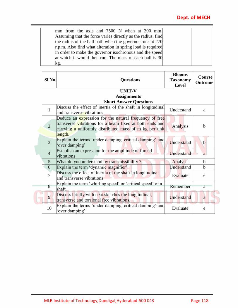
Dept. of MECH
MLR Institute of Technology,Dundigal,Hyderabad-500 043 Page 118
mm from the axis and 7500 N when at 300 mm.
Assuming that the force varies directly as the radius, find
the radius of the ball path when the governor runs at 270
r.p.m. Also find what alteration in spring load is required
in order to make the governor isochronous and the speed
at which it would then run. The mass of each ball is 30
kg.
Sl.No. Questions
Blooms
Taxonomy
Level
Course
Outcome
UNIT-V
Assignments
Short Answer Questions
1 Discuss the effect of inertia of the shaft in longitudinal
and transverse vibrations Understand a
2
Deduce an expression for the natural frequency of free
transverse vibrations for a beam fixed at both ends and
carrying a uniformly distributed mass of m kg per unit
length.
Analysis b
3 Explain the terms ‘under damping, critical damping’ and
‘over damping’ Understand b
4 Establish an expression for the amplitude of forced
vibrations Understand a
5 What do you understand by transmissibility ? Analysis b
6 Explain the term ‘dynamic magnifier’. Understand b
7 Discuss the effect of inertia of the shaft in longitudinal
and transverse vibrations Evaluate e
8 Explain the term ‘whirling speed’ or ‘critical speed’ of a
shaft. Remember a
9 Discuss briefly with neat sketches the longitudinal,
transverse and torsional free vibrations. Understand a
10 Explain the terms ‘under damping, critical damping’ and
‘over damping’ Evaluate e

Dept. of MECH
MLR Institute of Technology,Dundigal,Hyderabad-500 043 Page 119
Sl.No. Questions
Blooms
Taxonomy
Level
Course
Outcome
UNIT-V
Assignments
Long Answer Questions
1
An inside cylinder locomotive has its cylinder centre
lines 0.7 m apart and has a stroke of 0.6 m. The rotating
masses per cylinder are equivalent to 150 kg at the
crank pin, and the reciprocating masses per cylinder to
180 kg. The wheel centre lines are 1.5 m apart. The
cranks are at right angles. The whole of the rotating and
2/3 of the reciprocating masses are to be balanced by
masses placed at a radius of 0.6 m. Find the magnitude
and direction of the balancing masses. Find the
fluctuation in rail pressure under one wheel, variation
of tractive effort and the magnitude of swaying couple
at a crank speed of 300 r.p.m.
Understand a
2
A four cylinder vertical engine has cranks 150 mm
long. The planes of rotation of the first, second and
fourth cranks are 400 mm, 200 mm and 200 mm
respectively from the third crank and their reciprocating
masses are 50 kg, 60 kg and 50 kg respectively. Find
the mass of the reciprocating parts for the third cylinder
and the relative angular positions of the cranks in order
that the engine may be in complete primary balance.
Analysis b
3
The following data apply to an outside cylinder
uncoupled locomotive : Mass of rotating parts per
cylinder = 360 kg ; Mass of reciprocating parts per
cylinder = 300 kg ; Angle between cranks = 90° ; Crank
radius = 0.3 m ; Cylinder centres = 1.75 m ; Radius of
balance masses = 0.75 m ; Wheel centres = 1.45 m. If
whole of the rotating and two-thirds of reciprocating
parts are to be balanced in planes of the driving wheels,
find : 1. Magnitude and angular positions of balance
masses, 2. Speed in kilometres per hour at which the
wheel will lift off the rails when the load on each
driving wheel is 30 kN and the diameter of tread of
driving wheels is 1.8 m.
Understand b
4
A four cylinder vertical engine has cranks 150 mm
long. The planes of rotation of the first, second and
fourth cranks are 400 mm, 200 mm and 200 mm
respectively from the third crank and their reciprocating
masses are 50 kg, 60 kg and 50 kg respectively. Find
the mass of the reciprocating parts for the third cylinder
and the relative angular positions of the cranks in order
Remember a

Dept. of MECH
MLR Institute of Technology,Dundigal,Hyderabad-500 043 Page 120
that the engine may be in complete primary balance.
5
A five cylinder in-line engine running at 750 r.p.m. has
successive cranks 144° apart, the distance between the
cylinder centre lines being 375 mm. The piston stroke is
225 mm and the ratio of the connecting rod to the crank
is 4. Examine the engine for balance of primary and
secondary forces and couples. Find the maximum
values of these and the position of the central crank at
which these maximum values occur. The mass for each
cylinder is 15 kg.
Understand a
6
The three cylinders of an air compressor have their axes
120° to one another, and their connecting rods are
coupled to a single crank. The stroke is 100 mm and the
length of each connecting rod is 150 mm. The mass of
the reciprocating parts per cylinder is 1.5 kg. Find the
maximum primary and secondary forces acting on the
frame of the compressor when running at 3000 r.p.m.
Describe clearly a method by which such forces may be
balanced.
Evaluate e
7
A shaft carries five masses A, B, C, D and E which
revolve at the same radius in planes which are
equidistant from one another. The magnitude of the
masses in planes A, C and D are 50 kg, 40 kg and 80 kg
respectively. The angle between A and C is 90° and that
between C and D is 135°.Determine the magnitude of
the masses in planes B and E and their positions to put
the shaft in
complete rotating balance.
Understand a
8
A, B, C and D are four masses carried by a rotating
shaft at radii 100 mm, 150 mm, 150 mm and
200 mm respectively. The planes in which the masses
rotate are spaced at 500 mm apart and the
magnitude of the masses B, C and D are 9 kg, 5 kg and
4 kg respectively. Find the required mass A
and the relative angular settings of the four masses so
that the shaft shall be in complete balance.
Analysis b
9
A single cylinder engine runs at 250 r.p.m. and has a
stroke of 180 mm. The reciprocating parts has a mass of
120 kg and the revolving parts are equivalent to a mass
of 70 kg at a radius of 90 mm. A mass is placed
opposite to the crank at a radius of 150 mm to balance
the whole of the revolving mass and two-thirds of the
reciprocating mass. Determine the magnitude of the
balancing mass and the resultant residual unbalance
force when the crank has turned 30° from the inner
dead centre,
neglect the obliquity of the connecting rod.
Understand b

Dept. of MECH
MLR Institute of Technology,Dundigal,Hyderabad-500 043 Page 121
10
A four cylinder inline marine oil engine has cranks at
angular displacement of 90°. The outer
cranks are 3 m apart and inner cranks are 1.2 m apart.
The inner cranks are placed symmetrically
between the outer cranks. The length of each crank is
450 mm. If the engine runs at 90 r.p.m. and
the mass of reciprocating parts for each cylinder is 900
kg, find the firing order of the cylinders for
the best primary balancing force of reciprocating
masses. Determine the maximum unbalanced primary
couple for the best arrangement.
Understand a

Dept. of MECH
MLR Institute of Technology,Dundigal,Hyderabad-500 043 Page 122
12.0 MACHINE TOOLS (A50321)
12.1 COURSE DESCRIPTION:
Course Code A50321
Course Title MACHINE TOOLS
Course Structure Lectures Tutorials Practicals Credits
5 1 - 4
Course Coordinator P.Subramanyam, Asst.Professor
Team of Instructors G.Hima Bindu, Patan Rahim Khan
COURSE OVERVIEW:
At the very outset of engineering development materials were cut by means of simple hand
tools. Gradually, with the development of civilization and engineering, work done by hand
tools give way to the work performed by special machines which are called machine tools.
Hand tools are tools which are held and used by the hands for shaping and sizing a work
and there is no mechanism in them. The cutting away of the excess metal in the form of
chips or small pieces is simply done by the muscular efforts of man. As a result, the process
is time consuming and not give satisfactory surface finish. It includes files, saw, chisel,
scrapper, etc. which are very commonly used in bench and fitting works and assembly of
machines.
12.2 PREREQUISITES:
Level Credits Periods/Weeks Prerequisites
UG 4 4
Engineering Workshop, Production
Technology, Metallurgy & Materials
Science
12.3 MARKS DISTRIBUTIONS:
Session Marks (25M) University End
Exam Marks
Total
Marks
Continuous Assessment Tests (Midterm tests):
There shall be 2 midterm examinations. Each midterm
examination consists of one objective paper, one
subjective paper and four assignments. The objective
paper is for 10 marks and subjective paper is for 10
marks, with duration of 1 hour 20 minutes (20 minutes for
objective and 60 minutes for subjective paper).
Objective paper is set for 20 bits of – multiple choice
questions, fill-in the blanks, 10 marks. Subjective paper
contains of 4 full questions (one from each unit) of
which, the student has to answer 2 questions, each
question carrying 5 marks. First midterm examination
75 100

Dept. of MECH
MLR Institute of Technology,Dundigal,Hyderabad-500 043 Page 123
shall be conducted for 2.5 units of syllabus and second
midterm examination shall be conducted for another 2.5
units. 5 marks are allocated for Assignments. First two
assignments should be submitted before the
conduct of the first mid, and the second two assignments
should be submitted before the conduct of the second mid.
The total marks secured by the student in each midterm
examination are evaluated for 25 marks, and the average
of the two midterm examinations shall be taken as the
final marks secured by each candidate.
12.4 EVALUATION SCHEME:
S. No Component Duration Marks
1 I Mid Examination 1 hour and 20 min 20
2 I Assignment 5
3 II Mid Examination 1 hour and 20 min 20
4 II Assignment 5
MID Examination marks to be considered as average of above 2 MID’s
5 External Examination 3 hours 75
Total 75
COURSE OBJECTIVES:
1. To introduce students to the basic concepts of manufacturing via shaping, forming,
machining, CNC machining and assembly. To introduce students conventional
manufacturing processes.
2. To develop a knowledge of appropriate parameters to be used for various machining
operations.
3. To develop a knowledge of workshop practice and basic use of machine tools and
workshop equipment.
4. To introduce students to the role of manufacturing in an economy and to show the
relationship between design and manufacturing.
5. To make students aware of the necessity to manage manufacturing processes and
systems for the best use of material and human resources with particular emphasis on
product safety and environmental considerations.
6. To introduce students to the scientific principles underlying material behavior during
manufacturing processes so as to enable them to undertake calculations of forces, tool
stresses and material removal rates.

Dept. of MECH
MLR Institute of Technology,Dundigal,Hyderabad-500 043 Page 124
12.5 COURSE OUTCOMES:
1. An ability to understand the basic parameters in the metal cutting operation.
2. An Ability to Calculate analytically the forces and other parameter associated with
orthogonal cutting.
3. An Ability To Know the various cutting fluids and their application methods.
4. An ability To Understand the importance of lathe ,its many varieties and basic
structure of center lathe.
5. An ability to Understands operation of shaper, slotter , planer and drilling machine.
6. An ability To Know the various types of milling machine ,grinding machine, boring
machines and their application and their operations.
12.6 HOW PROGRAM OUTCOMES ARE ASSESSED:
Program Outcomes Level Proficiency
assessed by
a
An ability to apply knowledge of computing,
mathematical foundations, algorithmic principles, and
computer science and engineering theory in the
modeling and design of computer-based systems to real-
world problems (fundamental engineering analysis
skills)
H
Assignments
Midterm and
University
examinations
b
An ability to design and conduct experiments, as well as
to analyze and interpret data (information retrieval
skills)
H
Assignments
Midterm and
University
examinations
c
An ability to design , implement, and evaluate a
computer-based system, process, component, or
program to meet desired needs, within realistic
constraints such as economic, environmental, social,
political, health and safety, manufacturability, and
sustainability (Creative Skills)
S
Assignments
Midterm and
University
examinations
d An ability to function effectively on multi-disciplinary
teams (team work) N --
e
An ability to analyze a problem, identify, formulate and
use the appropriate computing and engineering
requirements for obtaining its solution (engineering
problem solving skills)
H
Assignments
Midterm and
University
examinations

Dept. of MECH
MLR Institute of Technology,Dundigal,Hyderabad-500 043 Page 125
f
An understanding of professional, ethical, legal, security
and social
issues and responsibilities (professional integrity)
N --
g
An ability to communicate effectively both in writing
and orally
(speaking / writing skills)
N --
h
The broad education necessary to analyze the local and
global impact of computing and engineering solutions
on individuals, organizations, and society (engineering
impact assessment skills)
N --
i
Recognition of the need for, and an ability to engage in
continuing
professional development and life-long learning
(continuing
education awareness)
H
Assignments
Midterm and
University
examinations
j A Knowledge of contemporary issues (social
awareness) N --
k
An ability to use current techniques, skills, and tools
necessary for
computing and engineering practice (practical
engineering analysis
skills)
N --
l
An ability to apply design and development principles
in the construction of software and hardware systems of
varying complexity (software hardware interface)
S
Assignments
Midterm and
University
examinations
m
An ability to recognize the importance of professional
development by pursuing postgraduate studies or face
competitive examinations that offer challenging and
rewarding careers in computing (successful career and
immediate employment).
N --
N=None S=Supportive H=Highly Related

Dept. of MECH
MLR Institute of Technology,Dundigal,Hyderabad-500 043 Page 126
12.7 JNTUH SYLLABUS:
UNIT – I Elementary treatment of metal cutting theory – Element of cutting process –
Geometry of single point tool and angles chip formation and types of chips – built up
edge and its effects chip breakers. Mechanics of orthogonal cutting – Merchant’s Force
diagram, cutting forces – cutting speeds, feed, depth of cut, tool life, coolants, mach
inability – Tool materials.
UNIT – II Engine lathe – Principle of working, specification of lathe – types of lathe –
work & tool holding devices-Taper turning thread, turning – for Lathes and attachments.
Turret and capstan lathes – Principal features of automatic lathes – classification – Single
spindle and multi-spindle automatic lathes – tool layout
UNIT – III Shaping slotting and planing machines – Principles of working – Principal
parts – specification classification, operations performed. Kinematic scheme of the
shaping slotting and planning machines, machining time calculations.
Drilling and Boring Machines – Principles of working, specifications, types,
operations performed – tool holding devices – twist drill – Boring machines – Fine
boring machines – Jig Boring machine. Deep hole drilling machine. Kinematics
scheme of the drilling and boring machines
UNIT – IV Milling machine – Principles of working – specifications – classifications of
milling machines – Principal features of horizontal, vertical and universal milling
machines – machining operations Types geometry of milling cutters – milling cutters –
methods of indexing – Accessories to milling machines, kinematic scheme of milling
cutters – milling cutters – methods of indexing. Lapping, honing and broaching machines
– comparison to grinding – lapping and honing. Kinematics scheme of Lapping, Honing
and Broaching machines. Constructional features of speed and feed Units, machining
time calculations
UNIT –V Grinding machine – Fundamentals – Theory of grinding – classification of
grinding machine – cylindrical and surface grinding machine – Tool and cutter grinding
machine special types of grinding machines – Different types of abrasives – bonds
specification of a grinding wheel and selection of a grinding wheel Kinematic scheme of
grinding machines.
Text Books:
T1. Production Technology by R.K. Jain and S.C. Gupta.
T2. Production Technology by H.M.T. (Hindustan Machine Tools).
Reference Books:
R1. Machine Tools – C.Elanchezhian and M. Vijayan / Anuradha Agencies Publishers.
R2.Workshop Technology – B.S.Raghu Vamshi – Vol II
R3. Principles of machine Tools/ Bhattacharya A and Sen.G.C./New central Book
Agency.
R4. Elements of Work Shop Technology- Vol-II/ Hajra chowdary/Media prometers.
R5. Fundamentals of Metal Machining and Machine tools/ Geofrey Boothroyd/McGraw
Hill.

Dept. of MECH
MLR Institute of Technology,Dundigal,Hyderabad-500 043 Page 127
12.8 COURSE PLAN:
At the end of the course, the students are able to achieve the following Course Learning
Outcomes.
Lecture.
No.
Course Learning
Outcomes Topics to be covered Reference
1
What is the main role of
machine tools in modern
industry?
Introduction, Importance of
machine tools in the modern
industry T1&R1
2 Describe the methods of
metal cutting . Methods of metal cutting T1&R1
3
What is the main
Elements used in
machining process
Elements of machining process T1&R1
4
State the Differences
between orthogonal and
oblique cutting
Differences between orthogonal
and oblique cutting T1&R1
5 Explain difference
types cutting tools Classification of cutting tools T1&R1
6 Illustrate Geometry of
single point cutting tool.
Nomenclature of single point
cutting tool(Angles) T1&R1
7 Explain chip formation
types and their effects. Chip formation mechanism T2&R1
8 Explain difference types
of their effects.
Types of chips (Build up edge),
Tool failure, Chip breakers, T2&R1
9
Calculate tool life &
ORS System.
Tool life , Coolants or cutting
fluids, Mechanics of metal
cutting(Orthogonal cutting) T2&R1
10
Calculate Cutting
speed, feed and Tool
life.
Cutting Parameters ( Cutting
speed, feed, and depth of cut)
T2&R1
11 Evaluate kinematic
scheme of Lathe
Machinability, Cutting Tool
Material, T2&R1
12 Analyze the Merchant
force diagram.
Merchant force diagram(Cutting
force diagram) T2&R1
13
Calculate Cutting
speed, feed and Tool
life.
Constructional features of speed &
feed gear box. Kinematics of
Machine Tools, T2&R1
14 Describe the operation
of engine Lathe.
Engine lathe-principle of working,
specification of lathe, Operations T2&R1
15
Explain difference types
work holders & tool
holders.
Types of lathe, work holders, tool
holders.
16
Illustrate Geometry of
Box tools, taper turning,
threading –for lathes.
Box tools, taper turning, threading
–for lathes. T2 & R1
17 Categorize & Describe Lathe attachments. T2 & R1

Dept. of MECH
MLR Institute of Technology,Dundigal,Hyderabad-500 043 Page 128
lathe lathe attachments
18
Describe the operation
Turret and Capstan
lathes,
Turret and Capstan lathes, T2 & R1
19
Categorize & Describe the work holders and
tool holders.
Work Holding Devices(Collet
chucks, other work holders), tool
holding devices. T2 & R1
20 Explain the Turret and
Capstan lathes, Box and tool lay out. T2 & R1
21
Describe the Box and
tool lay out for
Automatic lathe.
Principle features of automatic
lathes-classification. T2 & R1
22
Describe the Operations
of Turret & Capstan
lathe.
Single spindle and multi spindle
automatic lathes, Tool lay out T2 & R1
23 Evaluate kinematic
scheme of Lathe Kinematic scheme of lathes, T2 & R1
24 Describe the shaping,
planning, slotting
Introduction to shaping, planning,
slotting T2 & R1
25
State the principle of
shaping, planning,
slotting
Principle of working to shaping,
planning, slotting T1 & T2
26 Categorize or Types of
shaper Classification or Types of shaper T1 & T2
27 State the principle of
shaping
Principle parts of shaper (Parts of
shaper) T1 & T2
28 State the Specification
of shaping specifications
T1 & T2
29 Describe the operation
of Shaping machine. Shaper operations
T1 & T2
30
Evaluate kinematic
scheme of Shaping,
slotting and planning
machine.
Kinematic schemes of shaping,
slotting, machines, planning
machines.
T1 & T2
31
State the machine
Machining time
calculations,
Machining time calculations, T1 & T2
32 Describe the Drilling
machine .
Introduction of Drilling machine-
principle, T1 & T2
33 State the Specification
of shaping, Specification of Drilling Machine
T1 & T2
34 Describe the operation
of Drilling Machine. Drilling M/C operations
T1 & T2
35
Categorize & Describe tool holding devices of
drilling.
Tool holding devices of drilling
machine T1 & T2

Dept. of MECH
MLR Institute of Technology,Dundigal,Hyderabad-500 043 Page 129
36 Explain difference
types of drills Types of drills ( Twist drill.)
T1 & T2
37 Describe the operation
of Boring Machine. Boring Machine Operations T1&T2
38
Describe the Fine
boring machine, jig
boring machine .
Fine boring machine, jig boring
machine T1&T2
39 Evaluate kinematic
scheme of Drilling
Kinematic schemes of drilling,
boring machines T1&T2
40 State the principle of
milling machine. Milling machine-principle, T1&T2
41 State the Specification
of milling Specification, classification. T1&T2
42
Describe the
Horizontal milling
machine
Horizontal milling machine T1&T2
43 Describe the Vertical
milling machine Vertical milling machine T1&T2
44
Describe the
Universal milling
machine
Universal milling machine T1&T2
45 Illustrate Geometry of
milling cutters, Geometry of milling cutters, T1&T2
46 Describe the Milling
operations . Milling operations T1&T2
47
Categorize & Describe Milling Attachment
(Accessories of milling
machine).
Milling Attachment (Accessories
of milling machine). T1&T2
48 Describe attachment
methods of indexing Methods of indexing R1
49 Evaluate kinematic
scheme of Milling.
Kinematic scheme of milling
cutters. R1
50 Describe the operation
of grinding,. Introduction to grinding, R1
51 Categorize Theory of
grinding. Theory of grinding. R1
52 Explain difference types
of grinding machines.
Classifications of grinding
machines. R1
53
Describe the
Cylindrical and surface
grinding machines
Cylindrical and surface grinding
machines R1
54 Explain Tool and cutter
grinding machine. Tool and cutter grinding machine. R1
55
Explain the Special
types of grinding
machines.
Special types of grinding
machines.
Types of abrasives, bonds. T2

Dept. of MECH
MLR Institute of Technology,Dundigal,Hyderabad-500 043 Page 130
T1. Production Technology by R.K. Jain and S.C. Gupta.
T2. Production Technology by H.M.T. (Hindustan Machine Tools).
R1. Machine Tools – C.Elanchezhian and M. Vijayan / Anuradha Agencies Publishers.
R2.Workshop Technology – B.S.Raghu Vamshi – Vol II
R3. Principles of machine Tools/ Bhattacharya A and Sen.G.C./New central Book
Agency.
R4. Elements of Work Shop Technology- Vol-II/ Hajra chowdary/Media prometers.
R5. Fundamentals of Metal Machining and Machine tools/ Geofrey Boothroyd/McGraw
Hill.
12.9 MAPPING COURSE OBJECTIVES LEADING TO THE ACHIEVEMENT
OF PROGRAM OUTCOMES:
Program Outcomes
a b c d e f g h i j k l m
I H S
II H
III H S
IV H S
V S S
S= Supportive H=Highly Relative
56
Categorize the bonds
Specification of grinding
wheel.
Bonds Specification of grinding
wheel. T2
57 How to selection of
grinding wheel
Selection of wheel, Kinematic
scheme of grinding machine. T2
58 Describe the Lapping,
honing, broaching.
Introduction to Lapping, honing,
broaching. T2
59
Differentiate the
grinding, lapping,
honing.
Comparison of grinding, lapping,
honing. T2
60
Evaluate kinematic
scheme of lapping,
honing, broaching
machines..
Kinematic schemes of lapping,
honing, broaching machines. T2
61
State the machine
Machining time
calculations
Constructional features of speed,
Feed units. Machining time
calculations, T2

Dept. of MECH
MLR Institute of Technology,Dundigal,Hyderabad-500 043 Page 131
12.10 MAPPING COURSE OUTCOMES LEADING TO THE ACHIEVEMENT
OF PROGRAM OUTCOMES:
Program Outcomes
a b c d e f g h i j k l m
1 H H
2 H S H
3 H S H
4 S H
5 H H
S= Supportive H=Highly Relative
12.11 OBJECTIVE QUESTIONS:
UNIT-I
1. A built –up-edge is formed while machining [ B ]
a) Ductile materials at high speed
b)Ductile materials at low speed
c)Brittle materials at high speeds
d)Brittle materials at low speeds
2. A single point tool has the following specifications in ASA system 8, 7, 5, 6, 10, 9, 1.5
The number 1.5represents [ D ]
a)Bake rake angle
b)End relief angle
c)Side relief angle
d)Nose radius
3. Tool signature means [ B ]
a) The impression of the tool taken on a paper for any reference
b) A numerical method of identification of tool
c) The plan of tool
d) The signature of operator using the tool
4. According to ASA a tool signature is given as 10, 10, 6, 6, 8, 8, 2. The number 6 indicates [ C ]
a) Rake Angle
b) Cutting Edge Angle
c) Relief Angle
d) Nose Radius

Dept. of MECH
MLR Institute of Technology,Dundigal,Hyderabad-500 043 Page 132
5. Discontinuous chips will be formed when machining speed is [ B ]
a) High
b) Low
c) Medium
d) Away from the design value
6. Machinability of a metal is determined by [ A ]
a) Machinability Index
b) Maximum possible cutting speed
c) Maximum possible depth of cut
d) Maximum surface finish per cut
7. Recognize the metal cutting element [ B ]
a) Feed
b) Tool Holding Device
c) Depth of cut
d) Speed
8. In orthogonal cutting system, cutting edge is [ B ]
a) In line with direction of tool travel
b) Perpendicular to direction of tool travel
c) Perpendicular to shear plane
d) At 300 to the cutting plane
9. The spindle speeds of machine tools are usually designed to follow: [ B ]
a)Arithmetic progressiob) Geometric progression
c) Harmonic progression
d) Logarithmic progression
10. The primary clearance angle in milling cutter provided for Aluminum, Brass etc. is of
the order [ A ]
a) 10 – 12
b) 1 – 2
c) 5 – 10
d) 4 – 7
11. The cutting speed is Maximum while machining -------------with high speed steel tool.
[ D ]
a) Cast Iron
b) Mild steel
c) Brass
d) Aluminium
12. The width of cutting edge of parting tool varies from-------- [ A ]
a) 3 – 12mm
b) 5 – 20mm
c) 8 – 30mm
d) 15 – 40mm

Dept. of MECH
MLR Institute of Technology,Dundigal,Hyderabad-500 043 Page 133
13. Cutting fluids mostly used for machining steel is ----------------- [ B ]
a) Water
b) Soluble oil
c) Dry
d) Heavy oil
14. When cutting face of tool is 900 to the line of action of tool then it is known as -[ B ]
a) Oblique cutting
b) Orthogonal cutting
c) ASA System
d) ORS System
15. Work done in metal cutting is depends on ---------------------- [ A ]
a) Cutting force & Cutting speed
b) Cutting speed & heat generated
c) Depth of cut & cutting speed
d)Depth of Cut & Cutting Force
16. -------------Gives best finish [ C ]
a) Lower cutting speed & higher feed
b) Higher cutting speed & higher feed
c) Higher cutting speed & fine feed
d) All the above
17. As the cutting speed increases tool cutting forces---------------- [ C ]
a) Remains constant
b) Increases
c) decreases
d)None
18. Larger end cutting edge angle --------------Tool life [ A ]
a) Increases
b) decreases
c) No effect
d)all the above
19. ------------are most commonly used for measuring force in metal cutting [ A ]
a) Mechanical & Strain gauge dynamometer
b) Calorimeter
c) Wattmeter
d)Ammeter
20. Surface which face the work piece is known as--------------of the tool [ A ]
a) Flank
b) Heel
c) Base
d) Top Angle

Dept. of MECH
MLR Institute of Technology,Dundigal,Hyderabad-500 043 Page 134
UNIT-II
1. Capstan and turret lathes are usually used [ D ]
a) To make small components
b) To make large components
c) For ordinary work
d) For mass production
2. Which of the following is not used as work holding device [ D ]
a) Chuck
b) Angle plate
c) Face plate
d) Carriage
3. The lathe that can accommodate maximum number of tools is [ D ]
a) Engine lathe
b) Tool room lathe
c) Copy lathe
d) Capstan and Turret lathe
4. Tail stock set over method of taper Turning is preferred for [ C ]
a) Internal tapers
b) small tapers
c) long slender tapers
d)step tapers
5. Half nut mechanism is employed while performing __________ operation in lathe [ C ]
a) Under cutting
b) plain turning
c)thread cutting
d)taper turning
6. Which the following is lathe accessory [ C ]
a) Head stock
b) compound rest
c) lathe carrier
d) tool post
7. Enlarging an existing hole with a rotating single point tool is called [ A ]
a) boring
b) drilling
c) reaming
d) internal turning
8. The lathe spindle is generally provided with a taper of [ D ]
a) 1 in 5
b) 1 in 10
c) 1 in 15
d) 1 in 20

Dept. of MECH
MLR Institute of Technology,Dundigal,Hyderabad-500 043 Page 135
9. Generally lathe tool is made of ______________ steel [ D ]
a) Iron
b) Aluminum
c) Cast Iron
d) High Speed Steel
10. The lathe with 15 cm center height would have a swing over the bed as [ A ]
a) 30cm
b) 15cm
c) 45 cm
d) 60 cm
10. The lathe with 15 cm center height would have a swing over the bed as [ A ]
a) 30cm
b) 15cm
c) 45 cm
d) 60 cm
11. Which operations are performed in lathe [ D ]
a) Undercut
b) Threading
c) Facing
d) All of These
12. Lathe bed is made of [ D ]
a) Wood
b) Steels
c) Plastic
d) Cast Iron
13. The movement of the cutting tool in lathe is [ B ]
a) Static
b) Moved
c) Not necessary
d) All of these
14. Most of the cases lathe is preferred to machining of [ B ]
a) Square
b) Cylindrical
c) Rectangular
d) Any Shape
15. In lathe the tool post is arranged in _________side [ A ]
a) Above
b) Below
c) Right side
d) Left side

Dept. of MECH
MLR Institute of Technology,Dundigal,Hyderabad-500 043 Page 136
16. Short work piece is hold in [ A ]
a) Chuck
b) Tail Stock
c) Carriage
d) Lathe bed
17. Between center are used in lathe for ________Work [ C ]
a) Cutting
b) Shaping
c) Holding
d) All of these
18. For capstan and turret lathes turret head is used or not. [ A ]
a) Yes
b) No
c) May be
d) All of these
19. Steady Rest is also called [ B ]
a) Head stroke
b) Centre Rest
c) Chuck
d) Tool Post
20. Lathe dogs are made up of [ C ]
a) Wood
b) Plastics
c) Metal
d) Non of above.
UNIT-III
1. Reciprocation of the cutting tool in shaping machines is accomplished by [ D ]
a. Rack pinion mechanism
b. Crank and connecting rod mechanism
c. Cam and cam follower mechanism
d. Oscillating lever mechanism
2. Internal keyway in gears can be cut in [ C ]
a. Shaping machine
b. Planing machine
c. Slotting machine
d. None of the above
3. The job reciprocates in [ B ]
a. Shaping machine
b. Planing machine
c. slotting machine
d. All of the above

Dept. of MECH
MLR Institute of Technology,Dundigal,Hyderabad-500 043 Page 137
4. The T-slots in the table of planing machines are cut in [ B ]
a. Shaping machine
b. Planing machine
c. Slotting machine
d. None of the above
5. Flat surface can be produced in [ D ]
a. Shaping machine only
b. Planing machine only
c. Slotting machine only
d. All of the above
6. Large number of cutting tool [ B ]
s can be simultaneously used in
a. Shaping machine
b. Planing machine
c. Slotting machine
d. None of the above
7. Heavy cuts can be given during machining in [ B ]
a. Shaping machine
b. Planing machine
c. Slotting machine
d. None of the above
8. Slotting machines are used to cut internal gear teeth for [ A ]
a. Batch production
b. Lot production
c. Mass production
d. None of the above
9. The work-table can rotate in [ C ]
a. Shaping machine
b. Planing machine
c. Slotting machine
d. None of the above
10. Length of the stroke can be varied in [ B ]
a. Shaping machine
b). Planing machine
c). Slotting machine
d). All of the above

Dept. of MECH
MLR Institute of Technology,Dundigal,Hyderabad-500 043 Page 138
11. The table in a slotter is a [ B ]
a) Square Table
b) Circular Table
c) Rectangular Table
d) Semi – circular Table
12. Normally shaping machine is used for producing [ C ]
a) Threads
b) Cylindrical surfaces
c) Surfaces composed of straight line elements
d) Cylindrical holes.
13. In a planer [ D ]
a) The tool is rotated
b) The tool is reciprocated
c) The job is rotated
d) The job is reciprocated
14. Size of a shaper is given by [ A ]
a) stroke length
b) motor power
c)weight of machine
d)table size
15. In a mechanical shaper the lifting of the tool during idle stroke is ensured by [ D ]
a) tool head
b) ratchet and pow mechanism
c) ram adjustment
d)clamper box mechanism
16. If the speed of Forward Stroke in a shaper is 12 m/min, the speed of Backward Stroke
should be [ C ]
a) 6 or 15 m/min
b) 12 m/min
c) 8 or 18 m/min
d) 6 or 24 m/min
17. Drill bushes are made up of [ D ]
a) High Speed Steel
b) Aluminum
c) Low carbon steels
d) High Carbon Steels, hardened and ground
18. Drill bushes are made up of [ B ]
a) High Speed Steel
b) Aluminum
c) Low carbon steels
d) High Carbon Steels, hardened and ground

Dept. of MECH
MLR Institute of Technology,Dundigal,Hyderabad-500 043 Page 139
19. Drill chucks are used for holding
[ B ]
a) Taper shank drills
b) Straight shank drills
c) Hexagonal shank drills
d) Square shank drills
20. In reaming process [ C ]
a) Metal removal rate is high
b) position of drilled hole is corrected
c) high form accuracy is obtained
d) high dimensional accuracy is obtained
UNIT-IV
1. In a milling operation, two side milling cutters are mounted with a desired distance between them
so that both sides of a wok piece can be milled simultaneously. This set up is called
(a) Gang milling
(b) straddle milling
(c) Side milling
(d) slab milling [ B ]
2. A milling cutter having 8teeth is rotating at 150 rpm. If feed per tooth is 0.1mm,the value of the
table speed in mm/minis [ A ]
(a) 120
(b) 187
(c) 125
(d) 70
3. Indexing is applied to ______________ machines [ A ]
(a) milling
(b) grinding
(c) lapping
(d) honing
4. The angle included between the land and the face of the tooth of a milling cutter is called
a) Lip Angle b) Rake Angle c) Cutting Angle d) Chisel Edge Angle [ A ]
5. Standard taper generally used on milling machine is [ B ]
a) Morse
b) Brown and Sharpe
c) Chapman
d) Seller's
6. In a milling cutter, the angle between the land of a tooth and the tangent to the outside diameter
of he cutter at the cutting edge of the tooth is called [ C ]
a) Lip Angle
b) Rake Angle
c) Relief Angle
d) Chisel Edge Angle

Dept. of MECH
MLR Institute of Technology,Dundigal,Hyderabad-500 043 Page 140
7. The arbor of the milling machine is used to hold [ A ]
a) Cutting tool
b) Spindle
c) Over arm
d) Mandrel
8. Feed rate in milling operation is expressed as [ A ]
a) mm/tooth
b) mm/rpm of the milling cutter
c) meters/minute
d) Revolution per minute.
9. Very thin chips with end mills [ A ]
a) Dull the cutting edge quickly
b) Improve tool life
c) Sharpen the cutting edge
d) Cause chipping of the cutting
10. The angle included between the land and the face of the tooth of a milling
cutter is called …….. [ B ]
a)Rake angle
b) Lip Angle
c)Cutting angle
d)Nose angle
11. The surface finish obtained in broaching operation is of the order of [ B ]
(a) 8 micron
(b)0.8 micron
(c) 0.08 micron
(d) 0.008 micron
12. The maximum depth of cut which the tooth of a broach cuts is [ B ]
(a) I mm (b) 0.15 nim (c) 0.01 mm (d) 0.5 mm
13. A broach has
(a) roughing teeth, semifinishing teeth and finishing teeth [ A ]
(b) roughing teeth and finishing teeth
(c) only finishing teeth
(d)Non of above
14. The pitch for teeth of internal brooches is given by the relation: [ B ]
(a) 0.35 times length of cut in mm.
(b) 1.25 to 1.5 times length of cut in mm
(c) 4 times length of cut in mm
(d) None of the above

Dept. of MECH
MLR Institute of Technology,Dundigal,Hyderabad-500 043 Page 141
15. For proper broaching. at least the following number of teeth should be in the work at a time
[ C ]
(a) 1
(b) 2
(c) 3
(d) 0
16. Choose the wrong statement: In broaching [ B ]
(a) the job is completed in one stroke of the machine
(b) the tooling WU is low
(c) the rate of production is high
(d)Non of above
17. The finishing teeth of a broaching tool are provided with [ B ]
(a) large amount of land
(b) smaller amount of land
(c) no land
(d)Non of above
18. The range of hardness of the material which can be broached is [ B ]
(a) 10 to 20 Rockwell C
(b) 25 to 40 Rockwell C
(c) 60 to 80 Rockwell C
(d)Non of above
19. Broaching is primarily done for [ C ]
(a) better finish
(b) cylindrical jobs
(c) mass production
(d) hard materials
20. The broaching operation in which the tool moves past the stationary work is[ D ]
(a) push broaching
(b) pull broaching
(c) continuous broaching
(d) surface broaching I
UNIT-V
1. In a milling operation, two side milling cutters are mounted with a desired distance between them
so that both sides of a wok piece can be milled simultaneously. This set up is called
(a) Gang milling
(b) straddle milling
(c) Side milling
(d) slab milling [ B ]

Dept. of MECH
MLR Institute of Technology,Dundigal,Hyderabad-500 043 Page 142
2. A milling cutter having 8teeth is rotating at 150 rpm. If feed per tooth is 0.1mm,the value of the
table speed in mm/minis [ A ]
(a) 120
(b) 187
(c) 125
(d) 70
3. Indexing is applied to ______________ machines [ A ]
(a) milling
(b) grinding
(c) lapping
(d) honing
4. The angle included between the land and the face of the tooth of a milling cutter is called
a) Lip Angle
b) Rake Angle
c) Cutting Angle
d) Chisel Edge Angle [ A ]
5. Standard taper generally used on milling machine is [ B ]
a) Morse
b) Brown and Sharpe
c) Chapman
d) Seller's
6. In a milling cutter, the angle between the land of a tooth and the tangent to the outside diameter
of the cutter at the cutting edge of the tooth is called [ C ]
a) Lip Angle
b) Rake Angle
c) Relief Angle
d) Chisel Edge Angle
7. The arbor of the milling machine is used to hold [ A ]
a) Cutting tool
b) Spindle
c) Over arm
d) Mandrel
8. Feed rate in milling operation is expressed as [ A ]
a) mm/tooth
b) mm/rpm of the milling cutter
c) meters/minute
d) Revolution per minute.
9. Very thin chips with end mills [ A ]
a) Dull the cutting edge quickly
b) Improve tool life
c) Sharpen the cutting edge

Dept. of MECH
MLR Institute of Technology,Dundigal,Hyderabad-500 043 Page 143
d) Cause chipping of the cutting
10. The angle included between the land and the face of the tooth of a milling
cutter is called …….. [ B ]
a)Rake angle
b) Lip Angle
c)Cutting angle
d)Nose angle
11. The surface finish obtained in broaching operation is of the order of [ B ]
(a) 8 micron
(b)0.8 micron
(c) 0.08 micron
(d) 0.008 micron
12. The maximum depth of cut which the tooth of a broach cuts is [ B ]
(a) I mm
(b) 0.15 nim
(c) 0.01 mm
(d) 0.5 mm
13. A broach has
(a) roughing teeth, semifinishing teeth and finishing teeth [ A ]
(b) roughing teeth and finishing teeth
(c) only finishing teeth
(d)Non of above
14. The pitch for teeth of internal brooches is given by the relation: [ B ]
(a) 0.35 times length of cut in mm.
(b) 1.25 to 1.5 times length of cut in mm
(c) 4 times length of cut in mm
(d) None of the above
15. For proper broaching. at least the following number of teeth should be in the
work at a time. [ C ]
(a) 1
(b) 2
(c) 3
(d)0
16. Choose the wrong statement: In broaching [ B ]
(a) the job is completed in one stroke of the machine
(b) the tooling WU is low
(c) the rate of production is high
(d)Non of above

Dept. of MECH
MLR Institute of Technology,Dundigal,Hyderabad-500 043 Page 144
7. The finishing teeth of a broaching tool are provided with [ B ]
(a) large amount of land
(b) smaller amount of land
(c) no land
(d)Non of above
18. The range of hardness of the material which can be broached is [ B ]
(a) 10 to 20 Rockwell C
(b) 25 to 40 Rockwell C
(c) 60 to 80 Rockwell C
(d)Non of above
19. Broaching is primarily done for [ C ]
(a) better finish
(b) cylindrical jobs
(c) mass production
(d) hard materials
20. The broaching operation in which the tool moves past the stationary work is[ D ]
(a) push broaching
(b) pull broaching
(c) continuous broaching
(d) surface broaching
12. 12 TUTORIAL QUESTIONS:
Sl.No. Questions
Blooms
Taxonomy
Level
Course
Outcome
UNIT-I
Tutorials
Short Answer Questions
1
What are the types of tool materials used in metal
cutting? Discuss their
importance.
Knowledge a
2 What are the different types of chips? Explain
Machinability. Knowledge b
3 Explain the effect of cutting fluids on chip
contraction. Analysis e
4 Discuss the various forces encountered in metal
cutting. comprehension c
5 Describe the effect of cutting fluid on cutting speed
and tool life comprehension a
6 Define various angle of single point nomenclature Knowledge a

Dept. of MECH
MLR Institute of Technology,Dundigal,Hyderabad-500 043 Page 145
with example?
7 Explain briefly about effects of cutting fluids while
during metal cutting? Knowledge a
8 Distinguish between ASA and ORS systems? Analysis a
9 How to identify the tool life? Analysis a
10 State the differences Feed and Depth of Cut? Knowledge b
Sl.No. Questions
Blooms
Taxonomy
Level
Course
Outcome
UNIT-I
Tutorials
Long Answer Questions
1 Discuss the various forces encountered in metal
cutting. Knowledge a
2 What are the types of tool materials used in metal
cutting? Discuss their importance. Knowledge a
3 With the help of neat sketch, explain the tool
geometry. Analysis a
4 Describe the effect of cutting fluid on cutting speed
and tool life. comprehension b
5 What are the different types of chips? Explain
Machinability. comprehension a
6
Explain the following types of cutting fluids: i. Water
based cutting fluids ii. Straight or neat oil based
cutting fluids.
Knowledge b
7 Explain the effect of cutting fluids on chip
contraction. Knowledge e
8 Explain the factors used for judging the
Machinability. Analysis c
9 Discuss the various forces encountered in metal
cutting. Analysis a
10 What are the types of tool materials used in metal
cutting? Discuss their importance. Knowledge a

Dept. of MECH
MLR Institute of Technology,Dundigal,Hyderabad-500 043 Page 146
Sl.No.
Questions Blooms
Taxonomy
Level
Course
Outcome
UNIT-II
Tutorials
Short Answer Questions
1 List out various types of lathes? Analysis b
2 State the differences between engine lathe and centre
lathe? comprehension a
3 Explain the four types of operations that need to lathe
machining? comprehension b
4 Differentiate the tool setup for face turning and plain
turning? Analysis e
5 Explain briefly about taper turning methods? Knowledge b
6 Discuss the various tool holding devices for lathe? comprehension a
7 List out the two mandrel? Analysis b
8 Define lathe dogs? Explain how it is used to lathe? Knowledge e
9 Discuss the lathe carriers? And its applications. Knowledge a
10 Write the full classification of lathe? Knowledge a
Sl.No.
Questions Blooms
Taxonomy
Level
Course
Outcome
UNIT-II
Tutorials
Long Answer Questions
1 Explain briefly the working principle of a lathe with
diagram . Analysis b
2 Name any six work-holding devices and explain
briefly. comprehension a
3 Draw the sketch of capstan lathe mention parts. comprehension b
4 Compare an engine lathe with capstan and turret
lathe. Analysis e
5 Explain six operations for lathe: Knowledge b
6 What are the chief distinguishing features of a turret
lathe as compared to an engine lathe? comprehension b
7 What is meant by ‘tool layout’ of a turret lathe? Analysis a
8 Explain the advantages and disadvantages of a turret
lathe. Knowledge b
9 Explain briefly the working principle of a lathe with
diagram . Knowledge e
10 Name any six work-holding devices and explain
briefly. Knowledge b

Dept. of MECH
MLR Institute of Technology,Dundigal,Hyderabad-500 043 Page 147
Sl.No. Questions
Blooms
Taxonomy
Level
Course
Outcome
UNIT-III
Short Answer Questions
1 How to classify the shaper? Knowledge b
2 Explain the following related operations to address the
tool: a. Horizontal Cutting b. Inclined Cutting Knowledge e
3 Explain the principle of slotting machine? Analysis b
4 Discuss advantages of disadvantages of shaper
operations over slotting operations? comprehension a
5 Explain the principle of slotting machine? comprehension b
6 Discuss advantages of disadvantages of shaper
operations over slotting operations? Knowledge e
7 Explain the following mechanism A. Whit-worth quick
return B. Crank and slotted lever Knowledge b
8 Explain the feed mechanism in shaper? Analysis e
9 Differentiate between mechanical shaper and hydraulic
shaper? Analysis b
10 6. Define the various work holding devices for shaper,
slotter and planer? Knowledge a
Sl.No. Questions
Blooms
Taxonomy
Level
Course
Outcome
UNIT-III
Long Answer Questions
1 Draw the block diagram of a horizontal shaper and
write about its important parts. Knowledge b
2 What are the main operations performed on a planer? Knowledge e
3 Describe with a schematic sketch the operation of a
hydraulic shaper and explain. Analysis b
4 Write the planning machine working principle and its
applications. comprehension a
5 Sketch and explain the hydraulic drive of a horizontal
shaper. comprehension b
6
Name the common work-holding devices used on
shaper planers. With the help of a neat sketch, describe
a planer vice.
Knowledge b
7 Describe with a schematic sketch the operation of a
hydraulic shaper and explain. Knowledge b
8 Write the planning machine working principle and its
applications. Analysis e
9 Explain any three methods of taper turning on a lathe. Analysis b
10 Draw the block diagram of a horizontal shaper and
write about its important parts. Knowledge a

Dept. of MECH
MLR Institute of Technology,Dundigal,Hyderabad-500 043 Page 148
Sl.No. Questions
Blooms
Taxonomy
Level
Course
Outcome
UNIT-IV
Tutorials
Short Answer Questions
1 What is a milling machine? How do you classify the
milling machine? Analysis b
2 Give the working principle of milling machine with a
neat sketch? comprehension e
3 Classifications of milling machines. comprehension b
4 Explain the importance of Universal milling machine Analysis a
5 Classifications of various milling cutters.? Knowledge b
6 What are the various milling operations? Explain with
the help of suitable sketches. comprehension b
7 Explain the following with neat sketches: Analysis e
8 Planer type milling machine. Knowledge b
9 Rotary table or continuous milling machine. Knowledge a
10 Mention the size and specification of milling machine? Knowledge b
Sl.No. Questions
Blooms
Taxonomy
Level
Course
Outcome
UNIT-IV
Tutorials
Long Answer Questions
1 What is a milling machine? How do you classify the
milling machine? Analysis b
2
Give the working principle of milling machine with a
neat sketch? Mention the size and specification of
milling machine?
comprehension e
3 Classifications of milling machines. comprehension b
4 Explain the importance of Universal milling machine Analysis a
5 Classifications of various milling cutters.? Knowledge b
6 What are the various milling operations? Explain with
the help of suitable sketches. comprehension e
7 Explain the following with neat sketches: Analysis b
8 Planer type milling machine. Knowledge a
9 Rotary table or continuous milling machine. Knowledge b
10 What is a milling machine? How do you classify the
milling machine? Knowledge e

Dept. of MECH
MLR Institute of Technology,Dundigal,Hyderabad-500 043 Page 149
Sl.No. Questions
Blooms
Taxonomy
Level
Course
Outcome
UNIT-V
Tutorials
Short Answer Questions
1 Explain the theory of grinding. What is the principle of
metal removal? Discuss the elements of grinding Knowledge b
2 What type of materials are used for grinding wheels?
Discuss the selection of grinding wheel. Knowledge e
3 What is indexing? Explain some common methods of
indexing in milling machines? Analysis b
4 Make a comparison of grinding machine with lapping. comprehension b
5 Explain Grinding processes with diagrams: comprehension e
6 Sketch a broaching tool and explain various elements. Knowledge b
7 How the length of a broach is determined? Explain. Knowledge a
8 What is indexing? Explain some common methods of
indexing in milling machines? Analysis b
9 Make a comparison of grinding machine with lapping. Analysis b
10
Differences between honing and broaching machines
with regard to the construction, working and
applications.
Knowledge e
Sl.No. Questions
Blooms
Taxonomy
Level
Course
Outcome
UNIT-V
Tutorials
Long Answer Questions
1
Give the working principle of milling machine with a
neat sketch? Mention the size and specification of
milling machine?
Knowledge b
2 Explain the importance of Universal milling machine Knowledge e
3 What are the various milling operations? Explain with
the help of suitable sketches. Analysis b
4 Planer type milling machine. comprehension a
5 Classifications of various milling cutters.? comprehension b
6 What are the various milling operations? Explain with
the help of suitable sketches. Knowledge b
7 Explain the following with neat sketches: Knowledge e
8 Planer type milling machine. Analysis b
9 Rotary table or continuous milling machine. Analysis b
10
Give the working principle of milling machine with a
neat sketch? Mention the size and specification of
milling machine?
Knowledge e

Dept. of MECH
MLR Institute of Technology,Dundigal,Hyderabad-500 043 Page 150
12. 13 ASSIGNMENT QUESTIONS:
Sl.No. Questions
Blooms
Taxonomy
Level
Course
Outcome
UNIT-I
Assignments
Short Answer Questions
1 Explain briefly about effects of cutting fluids while
during metal cutting? Evaluate e
2 Distinguish between ASA and ORS systems? Remember a
3 How to identify the tool life? Understand a
4 State the differences Feed and Depth of Cut? Evaluate e
5 Describe various types of work holding devices? Evaluate e
6 List out various parameters for improve the Tool life? Remember a
7 List out the two parameters for metal cutting? Understand a
8 Distinguish between ASA and ORS systems? Analysis b
9 How to identify the tool life? Understand b
10 State the differences Feed and Depth of Cut? Analysis b
Sl.No. Questions
Blooms
Taxonomy
Level
Course
Outcome
UNIT-I
Assignments
Long Answer Questions
1 Discuss the various forces encountered in metal
cutting. Evaluate e
2 What are the types of tool materials used in metal
cutting? Discuss their importance. Remember a
3 With the help of neat sketch, explain the tool
geometry. Understand a
4 Describe the effect of cutting fluid on cutting speed
and tool life. Evaluate e
5 What are the different types of chips? Explain
Machinability. Analysis b
6 List out elements of metal cutting? Understand b
7 Differentiate HSS and Tungsten Carbide Tools? Evaluate e
8 Write briefly about Chip formation? Remember a
9 Define the Chips? Understand a
10 List the various types chips? Evaluate e

Dept. of MECH
MLR Institute of Technology,Dundigal,Hyderabad-500 043 Page 151
Sl.No. Questions
Blooms
Taxonomy
Level
Course
Outcome
UNIT-II
Assignments
Short Answer Questions
1 Explain method of tail stock offset method? Understand a
2 State the differences between Engine lathe and
automatic lathe? Analysis b
3 Discuss the various work holding devices for lathe? Understand b
4 Discuss the various tool holding devices for lathe? Evaluate e
5 List out and explain any two types of mandrel? Remember a
6 Define lathe dogs? Explain how it is used to lathe? Understand a
7 Discuss the lathe carriers? And its applications. Understand a
8 Write the full classification of lathe? Analysis b
9 Explain method of tail stock offset method? Understand b
10 State the differences between Engine lathe and
automatic lathe? Evaluate e
Sl.No.
Questions Blooms
Taxonomy
Level
Course
Outcome
UNIT-II
Assignments
Long Answer Questions
1 List out various types of lathes? Remember a
2 State the differences between engine lathe and centre
lathe? Understand a
3 Explain the four types of operations that need to lathe
machining? Analysis b
4 Differentiate the tool setup for face turning and plain
turning? Understand b
5 Explain briefly about taper turning methods? Evaluate e
6 List out various types of lathes? Remember a
7 What is meant by ‘tool layout’ of a turret lathe? Understand a
8 Explain the advantages and disadvantages of a turret
lathe. Analysis b
9 Explain briefly the working principle of a lathe with
diagram . Understand b
10 Name any six work-holding devices and explain
briefly. Analysis b

Dept. of MECH
MLR Institute of Technology,Dundigal,Hyderabad-500 043 Page 152
Sl.No. Questions
Blooms
Taxonomy
Level
Course
Outcome
UNIT-III
Assignments
Short Answer Questions
1 Explain the principles of shaper, slotter, planer with
diagram? Analysis b
2 Illustrate the shaper operations based on principles. Understand b
3 How to recognize the slotter? Evaluate e
4 Draw the diagram of slotting machine Remember a
5 Design a whit-worth quick return mechanism for shape Understand a
6 Explain the principles of shaper, slotter, planer with
diagram? Analysis b
7 Illustrate the shaper operations based on principles. Understand b
8 Explain the feed mechanism in shaper? Analysis b
9 Differentiate between mechanical shaper and hydraulic
shaper? Understand b
10 6. Define the various work holding devices for shaper,
slotter and planer? Evaluate e
Sl.No. Questions
Blooms
Taxonomy
Level
Course
Outcome
UNIT-III
Assignments
Long Answer Questions
1 Draw the block diagram of a horizontal shaper and write
about its important parts. Evaluate e
2 What are the main operations performed on a planer? Remember a
3 Describe with a schematic sketch the operation of a
hydraulic shaper and explain. Understand a
4 Write the planning machine working principle and its
applications. Understand b
5 Sketch and explain the hydraulic drive of a horizontal
shaper. Evaluate e
6 Explain the principles of shaper, slotter, planer with
diagram? Understand b
7 Illustrate the shaper operations based on principles. Evaluate e
8 How to recognize the slotter? Remember a
9 Draw the diagram of slotting machine Understand a
10 Design a whit-worth quick return mechanism for shape Understand b

Dept. of MECH
MLR Institute of Technology,Dundigal,Hyderabad-500 043 Page 153
Sl.No. Questions
Blooms
Taxonomy
Level
Course
Outcome
UNIT-IV
Assignments
Short Answer Questions
1 What is a milling machine? How do you classify the
milling machine? Remember a
2 Give the working principle of milling machine with a
neat sketch? Understand a
3 Classifications of milling machines. Analysis b
4 Explain the importance of Universal milling machine Understand b
5 Classifications of various milling cutters.? Evaluate e
6 What are the various milling operations? Explain with
the help of suitable sketches. Evaluate e
7 Explain the following with neat sketches: Remember a
8 Planer type milling machine. Understand a
9 Rotary table or continuous milling machine. Understand b
10 Mention the size and specification of milling machine? Analysis b
Sl.No. Questions
Blooms
Taxonomy
Level
Course
Outcome
UNIT-IV
Assignments
Long Answer Questions
1 How to classify the milling cutters? Understand a
2
Define various clearance angles of multi point cutting
tool nomenclature with importance? Analysis b
3 Explain briefly about lapping process? Understand b
4 Distinguish between lapping and honing process? Understand a
5 State the differences lapping and honing with grinding? Analysis b
6
State the differences vertical and horizontal milling
machines? Understand b
7
Describe various types of work holding devices for
milling? Remember a
8 How to classify the milling cutters? Understand a

Dept. of MECH
MLR Institute of Technology,Dundigal,Hyderabad-500 043 Page 154
9 List out the two parameters for milling? Evaluate e
10 Define lapping? How it’s working?
Sl.No. Questions
Blooms
Taxonomy
Level
Course
Outcome
UNIT-V
Short Answer Questions
1 List out various types of abrasives and bonds? Understand a
2
State the differences between surface and cylindrical
grinders? Analysis b
3 Explain the importance of grinding operations? Understand b
4 Differentiate the grinding to other finishing processes? Understand a
5 Explain briefly about methods of methods? Analysis b
6 Define advance grinding processes with examples? Understand b
7 List the various types of grinding machines ? Evaluate e
8 Discuss the selection of grinding wheels? Remember a
9 Define the differentiate natural and artificial abrasives? Understand a
10
Why artificial abrasives are preferred for grinding
wheels? Evaluate e
Sl.No. Questions
Blooms
Taxonomy
Level
Course
Outcome
UNIT-V
Assignments
Long Answer Questions
1 Discuss the selection of bonds for grinding wheels? Understand a
2 Explain surface grinding machining process? Analysis b
3 Explain cylindrical grinding machining process? Understand b
4 State the differences between surface and cylindrical? Remember a
5
Discuss the various work holding devices grinding
machines? Understand a
6 Explain centreless grinding machining process? Evaluate e
7 List out and explain any two types of work holding Understand a

Dept. of MECH
MLR Institute of Technology,Dundigal,Hyderabad-500 043 Page 155
devices for grinding?
8
Define grinding operations? Explain any three
advantages with suitable examples? Analysis b
9
Discuss the Tool and cutter grinding machine? And its
applications. Understand b
10 Write the full classification of grinding machines? Understand a

Dept. of MECH
MLR Institute of Technology,Dundigal,Hyderabad-500 043 Page 156
13.0 DESIGN OF MACHINE MEMBERS-1 (A50316) 13.1 COURSE DESCRIPTION:
Course Code A50316
Course Title DESIGN OF MACHINE MEMBERS-I
Course Structure Lectures Tutorials Practicals Credits
5 1 - 4
Course Coordinator Dr.S.MadhuProfessor,Dr.M.S.M.Gupta Professor, Team of Instructors Ms.A.NaliniDeepthi Assistant Professor
COURSE OVERVIEW: The design of machine members-I focus mainly on design of Machine elements subjected to various types of loads and components include joints; Riveted, Welded, threaded joints shafts and springs. Design basis is strength and stiffness of the parts and selection of material for manufacture of machine elements.
13.2 PREREQUISITES:
Level Credits Periods/Weeks Prerequisites
UG 4 5
Engineering mechanics, Material Science and Engineering, Kinematics of machinery, Strength of Materials, Machine Drawing.
13.3 MARKS DISTRIBUTIONS:
Session Marks (25M) University End
Exam Marks
Total
Marks
Continuous Assessment Tests (Midterm tests):
There shall be 2 midterm examinations. Each midterm
examination consists of one objective paper, one
subjective paper and four assignments. The objective
paper is for 10 marks and subjective paper is for 10
marks, with duration of 1 hour 20 minutes (20 minutes for
objective and 60 minutes for subjective paper).
Objective paper is set for 20 bits of – multiple choice
questions, fill-in the blanks, 10 marks. Subjective paper
contains of 4 full questions (one from each unit) of
which, the student has to answer 2 questions, each
question carrying 5 marks. First midterm examination
shall be conducted for 2.5 units of syllabus and second
midterm examination shall be conducted for another 2.5
units. 5 marks are allocated for Assignments. First two
assignments should be submitted before the
conduct of the first mid, and the second two assignments
should be submitted before the conduct of the second mid.
The total marks secured by the student in each midterm
examination are evaluated for 25 marks, and the average
of the two midterm examinations shall be taken as the
final marks secured by each candidate.
75 100

Dept. of MECH
MLR Institute of Technology,Dundigal,Hyderabad-500 043 Page 157
13.4 EVALUATION SCHEME:
S. No Component Duration Marks
1 I Mid Examination 1 hour and 20 min 20
2 I Assignment 5
3 II Mid Examination 1 hour and 20 min 20
4 II Assignment 5
MID Examination marks to be considered as average of above 2
MID’s
5 External Examination 3 hours 75
Total 75
COURSE OBJECTIVES:
The objective of the course is to enable the student in; I. In design and analysis of load transmitting elements and selection of suitable materials and manufacture of these components. II. Analyzing the forces acting on various components and their design. III. Applying the theories of failure and select optimum design size for various
machine elements. IV. Understanding need for joints and their application for different purposes in
transmission of static loads.
13.5 COURSE OUTCOMES:
At the end of this course, the student shall have 1. Ability to identify design variables and performance factors in the study machine
elements.
2. Ability to identify different types of fastener and their basic features, related terminology and designations.
3. Ability to design lap and butt joints incase of riveted joints and to design welded
joints for given application. 4. Ability to design shafts for various types of loading.
5. Awareness of the basic features of springs, and means of transfer of motion
commonly used in mechanical engineering.

Dept. of MECH
MLR Institute of Technology,Dundigal,Hyderabad-500 043 Page 158
3.6HOW PROGRAM OUTCOMES ARE ASSESSED:
Program Outcomes Level Proficiency
assessed by
a
An ability to apply knowledge of computing, mathematical
foundations, algorithmic principles, and computer science and
engineering theory in the modeling and design of computer-
based systems to real-world problems (fundamental
engineering analysis skills)
H
Assignments
Midterm and
University
examinations
b An ability to design and conduct experiments, as well as to
analyze and interpret data (information retrieval skills) H
Assignments
Midterm and
University
examinations
c
An ability to design , implement, and evaluate a computer-
based system, process, component, or program to meet desired
needs, within realistic constraints such as economic,
environmental, social, political, health and safety,
manufacturability, and sustainability (Creative Skills)
S
Assignments
Midterm and
University
examinations
d An ability to function effectively on multi-disciplinary teams
(team work) N --
e
An ability to analyze a problem, identify, formulate and use
the appropriate computing and engineering requirements for
obtaining its solution (engineering problem solving skills)
H
Assignments
Midterm and
University
examinations
f
An understanding of professional, ethical, legal, security and
social
issues and responsibilities (professional integrity)
N --
g
An ability to communicate effectively both in writing and
orally
(speaking / writing skills)
N --
h
The broad education necessary to analyze the local and global
impact of computing and engineering solutions on individuals,
organizations, and society (engineering impact assessment
skills)
N --
i
Recognition of the need for, and an ability to engage in
continuing
professional development and life-long learning (continuing
education awareness)
H
Assignments
Midterm and
University
examinations
j A Knowledge of contemporary issues (social awareness) N --
k
An ability to use current techniques, skills, and tools necessary
for
computing and engineering practice (practical engineering
analysis
skills)
N --

Dept. of MECH
MLR Institute of Technology,Dundigal,Hyderabad-500 043 Page 159
l
An ability to apply design and development principles in the
construction of software and hardware systems of varying
complexity (software hardware interface)
S
Assignments
Midterm and
University
examinations
m
An ability to recognize the importance of professional
development by pursuing postgraduate studies or face
competitive examinations that offer challenging and rewarding
careers in computing (successful career and immediate
employment).
N --
N=None S=Supportive H=Highly Related
13.7 JNTUH SYLLABUS:
UNIT-I Introduction: General considerations in the design of Engineering Materials and their
properties–selection – Manufacturing consideration in design. Tolerances and fits – BIS
codes of steels. Theories of failure – Factor of safety – Design for strength and rigidity –
preferred numbers. Fatigue loading : Stress concentration–Theoretical stress Concentration factor–Fatigue
stressconcentration factor – Notch Sensitivity – Design for fluctuating stresses –
Endurance limit – Estimation of Endurance strength – Goodman’s life – Soderberg’s line.
UNIT-II Design of Fasteners:Riveted joints-methods of failure of riveted joints–strength equations–efficiencyof riveted joints – eccentrically loaded riveted joints. Welded Joints: Design of fillet welds-axial loads-circular fillet welds-bending-bolts of
uniform strength.
UNIT-III Keys, Cotters and Knuckle Joints: Design of Keys-stress in keys-cottered joints-spigot and socket,sleeve and cotter, jib and cotter joints-Knuckle joints.
UNIT-IV Design of Shafts: Design of solid and hollow shafts for strength and rigidity–Design of shafts forcomplex loads – Shaft sizes –BIS code – Design of shafts for gear and belt drives. Shaft couplings: Rigid couplings–Muff, Split muff and Flange couplings. Flexible couplings- PIN-Bushcoupling.
UNIT-V Mechanical Springs: Stresses and deflections of helical springs-extension compression
springs-springsfor static and fatigue loading-natural frequency of helical springs-energy
storage capacity-helical torsion springs-co-axial springs.

Dept. of MECH
MLR Institute of Technology,Dundigal,Hyderabad-500 043 Page 160
TEXT BOOKS: T1. P. Kannaiah, (2012), Machine Design, 2nd Edition, SciTech Publications India Pvt. Ltd, New Delhi, T2. V Bandari (2011), A Text Book of Design of Machine Elements, 3rd edition, Tata McGraw hilleducation (P) Ltd, New Delhi, India.
REFERENCE BOOKS: R1. Design of Machine Elements / V.M. Faires. R2. Machine design/Schaum Series. R3. Mechanical Engineering Design/JE Shigley. R4. Machine Design/S. Md. Jalaluddine/Anuradha Publishers. R5. R.L. Norton (2006), Machine Design ( An Integrated approach), 2nd edition,
Pearson Publishers, Chennai, India R6. Machine Design/UC Jindal/Pearson. R7. Design of Machine Elements (Vol.1)/T. Krishna Rao/IK International Publishing House/2nd Edition. R8. Machine Design / R.S Khurmi, A K Gupta

Dept. of MECH
MLR Institute of Technology,Dundigal,Hyderabad-500 043 Page 161
13.8 COURSE PLAN:
At the end of the course, the students are able to achieve the following Course Learning
Outcomes.
Lecture.
No.
Course Learning
Outcomes Topics to be covered Reference
1
Introduction
To understand the
machine
Members
UNIT-I
Introduction to machine design
T1&R1
2
Explain stages of
designprocedure
To know the types of
machine design
General considerations in the
design
Classification of Machine
Design , Design Procedure
T1&R1
3 Analyze various
properties ofmaterials
Engineering materials and their
properties T1&R1
4
List various preferred
numbers
Factor of safety – Design for
strength and rigidity – preferred
numbers.
T1&R1
5
Explain Stress
concentration
Stress concentration –
Theoretical stress
Concentration factor
T1&R1
6
To know the concept of
stress
concentration , different
types
of stress concentration
factors
and relation between
them
Stress Concentration and
factors(Kt, Kf), Notch
sensitivity
T1&R1
7
To know the stiffness of
the
component due to
different type
of loads.
Stiffness due to torsion,
bending & problems T1&R1
8
To calculate the failure
points for different
application of loads
combined variable normal
stress and variable shear
stress, problems
T1&R1
9
Differentiate
theoretical
stressconcentration
factor Fatigue stress
concentration
Fatigue stress concentration factor
– Notch Sensitivity T1&R1
10
Explain Endurance
limit
Explanation and problems
on stress concentration.
Endurance limit –
T1&R1

Dept. of MECH
MLR Institute of Technology,Dundigal,Hyderabad-500 043 Page 162
Estimation of Endurance
strength
11
Able to calculate the
stress
Concentration factor for
different features in
machine component.
Problems on Stress
Concentration. T1&R1
12
To Calculate the failure
points for different
application of loads
problems on Fatigue failure T1&R1
13
Explain design criteria
based onstrength and
rigidity
Goodman’s life – Soderberg’s
line.
Solutions of problems on various
types of loading
T2&R1
14 Explain various
types ofFasteners.
UNIT-II
Description of Fasteners methods T2&R1
15
Illustrate various types
ofriveted joints.
Explanation about Lap and but
joints and various parameters
involved in design of riveted
joints.
T2&R1
16
Calculate rivet
efficiency byusing
various strength
equations
efficiency of riveted
joints Calculate stress
induced in rivets
T2&R1
17
Solve problems on
riveted joints
Eccentrically loaded riveted
joints. Problems in design of
riveted joints.
T2&R1
18
To know the
different
applications of
riveted joints, design
procedure
Design of Rivetted joints,
problems
T2&R1
19
To Know the design
procedure for riveted
joints under Eccentric
loads
Eccentric loaded riveted
joints, problems
T2&R1
20 Explain various types of
weldedjoints.
Design of fillet welds-axial loads-
circular fillet welds T2&R1
21
Explain
procedure
forcalculating
size of weld
bending-bolts of uniform strength T2&R1
22 Describe various types
of bolts
Construction design and
proportions of bolts

Dept. of MECH
MLR Institute of Technology,Dundigal,Hyderabad-500 043 Page 163
23
Define pre-stresses
and stress induced in
working
Explanation of various stresses
induced in bolted joints and
solution of problems in various
applications
T2 & R1
24
Describe procedure for
findingsize of bolts
Explanation of the procedure for
finding
size of bolts
T2 & R1
25 Explain the locking
purpose
Bolted joints and associated
parts for locking purpose T2 & R1
26
To calculate the strength
for different applications
of load
strength of welded joints,
problems, strength of welded
joints, problems Axially loaded un
symmetrical sections
T2 & R1
27
To calculate the design
parameters for different
applications
problems on bolted joints T2 & R1
28
To calculate the design
parameters under
eccentric load
Problems on eccentric joints T2 & R1
29 Describe various type of
Keys,cotters and
knuckle joints
UNIT-III
Sketches for keys cotters
knuckle joints
and explanation of the purpose
of each
joint
T2 & R1
30
Explain procedure for
design of keys in
various applications
Design of Keys, stress in keys T2 & R1
31 Describe procedure for
design of cotter joint Cotter joints, Spigot and socket T2 & R1
32
To calculate the design
parameters of different
keys
Design of keys, problems T1 & T2
33 Describe procedure for
design of knuckle joint Jib and cotter joints, knuckle joint T1 & T2
34 Solve different problems
on different joints
Solution of problems under
application load T1 & T2
35
To know the design
procedure
and To calculate the
design
parameters of sleeve and
cotter Joint
Design of sleeve and cotter
joint, problems on design of
sleeve and cotter joints problems
T1 & T2
36
To know the design
procedure
and To calculate the
Design of knuckle joint,
problems T1 & T2

Dept. of MECH
MLR Institute of Technology,Dundigal,Hyderabad-500 043 Page 164
design
Parameters of knuckle
joint.
37 Calculating for
parameters of joints
Clear problems on knuckle joints
and cotter joints T1 & T2
38 Calculating for
parameters of joints
Clear problems on knuckle joints
and cotter joints T1 & T2
39
Explain concept of
power transmission of
power with shafts both
solid and Hollow
UNIT-IV
Formulas for determining size of
both hollow and solid shafts and
various conditions of loading for
strength and Rigidity criteria
T1 & T2
40
Describe design
procedure for
design of shafts for
complex
loads
Design of shafts for complex loads T1 & T2
41
Describe design
procedure for
finding loads and shafts
subjected to gear and
belt drives
Shaft sizes –BIS code
Applications and solution of
problems for
transmission of power by shafts
loaded
with belt and gear drives
T1 & T2
42
Describe various types
of couplings for power
transmission
Sketches of different couplings
and
various parameters to be explained
T1 & T2
43
Able to calculate the
shaft diameter under
different type of loads
Design of shaft based on
strength problems T1 & T2
44
Able to calculate the
shaft diameter under
different combination of
Loads
Shaft is subjected to Axial load
and combined bending and
torsional loads
T1&T2
45
Design procedure for
flexible couplings
Rigid couplings – Muff, Split
muff and
Flange couplings
T1&T2
46 Design procedure for
bush coupling PIN-Bush coupling. T1&T2
47 Design Calculations for
various couplings Problems of different couplings T1&T2
48
Able to calculate the
shaft diameter under
comparing rigidity
parameters and to know
the strength of hollow
shaft.
Design of shaft based on
rigidity and Design of hollow
shaft, problems
T1&T2
49 To know the shaft Design of rigid and T1&T2

Dept. of MECH
MLR Institute of Technology,Dundigal,Hyderabad-500 043 Page 165
coupling, and type of
couplings
flexible coupling
50
To know the design
procedure to calculating
design parameters of
clamp coupling
design of clamp coupling,
problems
T1&T2
51
To know the design
procedure to calculating
design parameters of
flange coupling
Flange coupling, design, problems
T1&T2
52
To know the design
procedure to calculating
design parameters of
marine type flange
coupling
Design of marine type flange
coupling, problems
T1&T2
53
To know the design
procedure to calculating
design parameters of
bushed-pin flexible
coupling
Design of Bushed-pin Flexible
coupling
T1&T2
54
Categories various types
of springs for
engineering applications
UNIT-V
Sketches of different springs with
relevant parameters Stresses and
deflections of helical springs
T1&T2
55 To know the mechanical
springs, applications
Introduction to mechanical
springs, types, applications. R1
56 To know the
terminology of springs Important terms of springs R1
57 To know the design
procedure Design of helical spring R1
58
Design procedure for
helical springs
extension compression springs-
springs for static and fatigue
loading
R1
59
To calculate the design
parameters under
different conditions
springs subjected to fatigue
load, problems R1
60
Explain fatigue loading-
natural frequency of
springs-energy storage
capacity
natural frequency of helical
springs-energy storage capacity R1
61 Describe Helical torsion
springs
Helical torsion springs-co-axial
springs. R1
62
To know the natural
frequency of spring,
calculate the energy
storage Capacity
Natural frequency of helical
springs, Energy storage
capacity
T2
63 To calculate strength Problems on springs T2
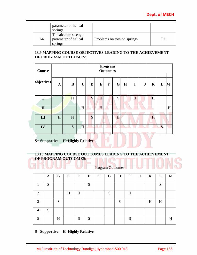
Dept. of MECH
MLR Institute of Technology,Dundigal,Hyderabad-500 043 Page 166
13.9 MAPPING COURSE OBJECTIVES LEADING TO THE ACHIEVEMENT
OF PROGRAM OUTCOMES:
Course
Program
Outcomes
objectives A
B
C
D
E
F
G
H
I
J
K
L
M
I H S H S H H
II H H H
III H H S H H
IV S H S
S= Supportive H=Highly Relative
13.10 MAPPING COURSE OUTCOMES LEADING TO THE ACHIEVEMENT
OF PROGRAM OUTCOMES:
Program Outcomes
A B C D E F G H I J K L M
1 S S S
2 H H S H
3 S S H H
4 S
5 H S S S H
S= Supportive H=Highly Relative
parameter of helical
springs
64
To calculate strength
parameter of helical
springs
Problems on torsion springs T2

Dept. of MECH
MLR Institute of Technology,Dundigal,Hyderabad-500 043 Page 167
13.11. Objective questions
UNIT 1
1. Hooks law holds good up to [ B ]
A) proportional limit B) elastic limit C) yield point D) none
2. Preferred numbers are arranged in [ C ]
A) arithmetic series B) hyperbolic series C) geometric series D) random series
3. The soderberg method is particularly used for _____________ materials. [ A ]
A) Ductile materials B) Brittle materials c) both a &B d) None
4. Rankines theory is used for _______________ materials. [ B ]
A) Ductile materials B) Brittle materials c) both a &B d) None
5. Residual stress in materials [ C ]
A) Acts when external load is applied
B) becomes zero when external load is removed
C) is independent of external loads
D) none
6. The fatigue life of a part can be improved by [ D ]
A) electro plating B) Polishing C) Coating D) Shot peening
7. A reciprocating steam engine connecting rod is subjected to a maximum load of 65
KN. Find the diameter of the connecting rod at its thinnest part, if the permissible
tensile stress is 35 N/mm2 [ A ]
A)50mm B) 60 mm C) 25mm D) 30mm
8. A wrought iron rod is under a compressive load of 350 KN. If the permissible stress
for the material is 52.5 N/mm2.Calculate the diameter of the rod. [ B ]
A)100mm B) 95 mm C) 80 mm D) 30mm
9. The maximum energy that can be stored in a body due to external loading up to the
elastic Limit is called____ [ B ]
A) Resilience B) Proof Resilience C) Strain energy D) Modulus of Elasticity
10. The poisons ratio for Steel varies from [ D ]
A) 0.21 to 0.25
B) 0.25 to 0.33
C) 0.33 to 0.38
D) 0.38 to 0.45
11. Theoretical stress concentration factor is defined as the ratio of [ C ]
A) Maximum stress to the endurance limit
B) nominal stress to the endurance limit
C) Maximum stress to the nominal stress
D) nominal stress to the maximum stress

Dept. of MECH
MLR Institute of Technology,Dundigal,Hyderabad-500 043 Page 168
12. Endurance limit is determined by attest, applying [ A ]
A) Completely reversed bending B) completely reversed axial loading
C) Completely reversed torsional loading D) any one of the above.
13. The fatigue life of a part can be improved by [ D ]
A) electro plating B) Polishing C) Coating D) Shot peening
14. A steel shaft 50mm diameter 500mm long is subjected to a twisting moment of 1100
N-M, the Total angle of twist being 0.60. Find the maximum shear stress developed
in the shaft [ D ]
A) 28.6 MPa B) 40 Mpa C) 30 Mpa D) 44.8 MPa
15. In the above problem calculate modulus of rigidity [ B ]
A) 80.3KN/mm2 B) 85.6KN/mm2 c) 88.3KN/mm2 D) None
16. The bending stress in a curved beam is [ C ]
A) Zero at the centroidal axis B) Maximum at the neutral axis
C) Zero at the point other than the centroidal axis D) None of the above
17. The maximum bending stress in a curved beam having symmetrical section always
occurs at the [ C ]
A) Centroidal axis B) Neutral axis C) Inside fiber D) Outside fiber
18. The neutral axis of a beam is subjected to [ A ]
A) Zero axis B) Maximum tensile stress
C) Maximum Compressive stress D) Maximum shear stress
19. Stresses induced in the shafts due to the transmission of torque. [ D ]
(a) Bending (b) Shear (c) Tensile (d) Compressive.
20. Two shafts A and B are made of the same material. The diameter of the shaft A is
twice as that of Shaft B. The power transmitted by the shaft A will be ............. times
of shaft B. [ C ]
A) 02 b) 03 c)08 d) 05
UNIT 2 1. The distance between the centers of the adjacent rivets in the same row is called [A]
A) Pitch B) margin C) row pitch D) diagonal pitch
2. Which of the following welded joint is designed for shear strength [B]
A) transverse fillet weld B) parallel fillet weld C) Butt weld D) all of the above
3. According to I.B.R, safety factor of rivet joint should not be less than ___. [ D ]
A)3 B) 2 C)5 D) 4
4. The strength of the unriveted or solid plate per pitch length is equal to ______ [ B ]
A) P*d*σt B) P*t*σt C)(p-t)d*σt D)(p-d)t*σt

Dept. of MECH
MLR Institute of Technology,Dundigal,Hyderabad-500 043 Page 169
5. A rivet is specified by [ A ]
A) Shank Diameter B) Length of the rivet C) Type Head D) Length of the tail
6. According to Indian standards, the diameter of the rivet hole for a 24mm diameter of
rivet should be [ C ]
A) 23mm B) 24mm C) 25mm D) 26mm
7. A lap joint is always in [ A ]
A) Single B) Double C) Both A &B D) None
8. A single riveted lap joint is made in 15 mm thick plates with 20mm diameter rivets.
Determine the strength of the joint if the pitch of rivets is 60mm. Take σt = 120 MPa
ґ= 90MPa and σc= 160Mpa [ A ]
A) 28280 N B) 3000N C) 43234 N D) None
9. For the above problem determine the efficiency of the joint [ D ]
A) 53.5% B) 60% C D) 63.5% D) None
10. The eye bolts are used for [ C ]
A) Transmission of power B) locking devices
C) lifting and transporting heavy machines D) Absorbing shocks and vibrations
11. A bolt of M24X3 means that _______. [ D ]
A) Pitch is 24 mm and Dia is 3mm B) Pitch dia is 24 and pitch is 3mm
C) Nominal Dia is 24mm and pitch is 3mm D)None
12. A bolt is specified by its ____. [ A ]
A) Nominal Diameter and pitch B) Pitch diameter
C) Only Nominal diameter D) None
13. The shock absorbing capacity of a bolt be increased by [ B ]
A) increasing its shank diameter B) decreasing the shank diameter
C) tightening the bolt properly
D) making the shank diameter equal to the core diameter
14. The principle of applying heat and pressure is widely used in [ D ]
A) Spot welding B) seam welding
C) projection welding D) all of these
15. The parallel fillet welded joint is designed for [ D ]
A) Tensile strength B) compressive strength
C) bending strength D) shear strength
16. The transverse fillet welded joint is designed for [ A ]
A) Tensile strength B) compressive strength
C) bending strength D) shear strength

Dept. of MECH
MLR Institute of Technology,Dundigal,Hyderabad-500 043 Page 170
17. The center to center distance between two consecutive rivets in a row, is called [ B]
A) margin B) pitch C) back pitch D) diagonal pitch
18. The resilience of a bolt may be increased by [ B ]
A) increasing its shank diameter B) increasing its length
C) Decreasing its shank diameter D) Decreasing its length
19. A bolt of uniform strength can be developed by [ A ]
A) Keeping the core diameter of threads equal to the diameter of unthreaded portion of
the bolt
B)Keeping the core diameter of threads smaller than the diameter of unthreaded portion
of the bolt
C) Keeping the nominal diameter of threads equal to the diameter of unthreaded portion
of the bolt
D) None of the above
20. According to Unwin’s formula, the relation between diameter of rivet hole (d) and
thickness of plate (t) is given by [ D ]
A) d=t B) d=1.6√𝑡 C) d=2t D) d=6t
UNIT 3
1. Which key transmits power through frictional resistance only [ D ]
A) Wood ruff key B) Kennedy C) Sunk D) Saddle
2. Shape of wood ruff key is like [ B ]
A) Cylinder B) Semicircle C) Sphere D) Tapered key
3. A key way lowers [ C ]
A) The strength of the shaft B) The rigidity of the shaft
C) Both the Strength and Rigidity of the shaft
D) the ductility of the material of the shafts.
4. A Cotter joint is used to transmit [ D ]
A) Axial tensile load only B) axial compressive load only
C) Combined axial and twisting loads D) Axial tensile or Compressive loads.
5. The permissible crushing stress for the usual key material is at least ___ [ A ]
permissible shearing stress.
A) Twice B) Thrice c) Equal d) None
6. The eye bolts are used for [ C ]
A) transmission of power B) locking devices
C) lifting and transporting heavy Machines
D) absorbing shocks and vibrations
7. A bolt of M24X3 means that _______. [ D ]
A) Pitch is 24 mm and Dia is 3mm B) Pitch dia is 24 and pitch is 3mm
C) Nominal Dia is 24mm and pitch is 3mm D)None

Dept. of MECH
MLR Institute of Technology,Dundigal,Hyderabad-500 043 Page 171
8. A bolt is specified by its ____. [ A ]
A) Nominal Diameter and pitch B) Pitch diameter
C) Only Nominal diameter D) None
9. The eye bolts are used for [ C ]
A) Transmission of power B) locking devices
C) lifting and transporting heavy machines D) absorbing shocks and vibrations
10. The shock absorbing capacity of a bolt be increased by [ B ]
A) increasing its shank diameter B) decreasing the shank diameter
C) tightening the bolt properly D) making the shank diameter equal to the core
diameter
11. An axle is subjected to [ A ]
A) Bending only B) Direct load only C) Torsion only D) All of the above
12. The design of shafts made of brittle materials is based on__ theory. [ B ]
A) Maximum Shear stress theory B) Rankines Theory C) Both A&B D) None
.
13. Stresses induced in the shafts due to the transmission of torque. [D]
A) Bending B) Shear C) Tensile D) Compressive.
14. Two shafts A and B are made of the same material. The diameter of the shaft A is
twice as that of shaft B. The power transmitted by the shaft A will be .............
times of shaft B. [ C ]
A) 02 B) 03 C)08 D) 05
15. A cotter joint is used to transmit [ D ]
A) Axial tensile load only B) axial compressive load only
C) Combined axial and twisting loads D) axial tensile or compressive loads
16.The taper on cotter varies from [ D ]
A) 1 in 15 to 1 in 10 B) 1 in 24 to 1 in 20
C) 1 in 32 to 1 in 24 D) 1 in 48 to 1 in 24
17. The length of cotter, in a sleeve and cotter joint, is taken as [ D ]
A) 1.5d B) 2.5d C) 3d 4) 4d
18. In a steam engine, the valve rod is connected to an eccentric by means of a [ A ]
A) Knuckle joint B) Universal joint C) Flange coupling D) Cotter joint

Dept. of MECH
MLR Institute of Technology,Dundigal,Hyderabad-500 043 Page 172
19.In a steam engine, the piston rod is connected to a crosshead by means of a [ D ]
A) Knuckle joint B) Universal joint C) Flange coupling D) Cotter joint
20. In a gib and cotter joint, the thickness of gib is _____ thickness of cotter [ C ]
A) more than B) less than C) equal to D) not equal to
UNIT 4
1. In a muff coupling, the effective length of the key is [ B ]
A) Equal to sleeve length B) Equal to half of the sleeve length
C) Double the sleeve length D) Independent of sleeve length
D) Absorbing shocks and vibrations
2. The design of shafts made of brittle materials is based on [ B ]
A)Guest’s theory B) Rankines theory C) St.Venants theory D) Von mises theory
3. A bolt is specified by its ____. [A]
A) Nominal `Diameter and pitch B) Pitch diameter C) Only Nominal diameterD)
None
4. A transmission shaft subjected to bending loads must be on the basis of [A]
A) Maximum normal stress theory B) maximum shear stress theory
C) Maximum normal stress and maximum shear stress theories
D) Fatigue strength
5. The shock absorbing capacity of a bolt be increased by [B]
A) increasing its shank diameter B) decreasing the shank diameter C) tightening the
bolt properly D) making the shank diameter equal to the core diameter
6.The maximum shear stress theory is used for [B]
A) Brittle materials B) ductile materials C) plastic materials D) non-ferrous materials
7. The standard length of the shaft is [D]
A) 5m B)6m C)7m D)all of these
8. The eye bolts are used for [C]
A) Transmission of power B) locking devices C) lifting and transporting heavy
machines
9. The maximum normal stress theory is used for [A]
A) Brittle materials B) ductile materials C) plastic materials D) non-ferrous
materials
10. A bolt of M24X3 means that _______. [D]
A) Pitch is 24 mm and Dia is 3mm B) Pitch dia is 24 and pitch is 3mm C)
Nominal Dia is 24mm and pitch is 3mm D)None
11. Two shafts A and B are made of the same material the diameter of shaft B is twice
that of shaft A. The ratio of power which can be transmitted by shaft A to that of
shaft B is ___________[A]
A) 1/8 b) 1/7 c) 1/5 1/9

Dept. of MECH
MLR Institute of Technology,Dundigal,Hyderabad-500 043 Page 173
12. The nature of stress induced in the holding down bolts in a compression coupling is _
[A]
A) Compressive stress B) Tensile Stress C) Bending Stress d) Shear stress
13. Hook’s coupling is used to connect two shafts whose axes intersect at a _____. [c]
A) A) Large angle B) 900 c) Small angle d) 450
14. The sleeve or muff coupling is designed as a [D]
A) Thin cylinder B) thick cylinder C) solid shaft D) hollow shaft
15. Oldham coupling is used to connect two shafts [C]
A) Which are perfectly aligned B) which are not in exact alignment
C) Which have lateral misalignment D) whose axes intersect at a small angle
16. When a shaft is subjected to a bending moment M and a twisting moment T, then the
equivalent twisting moment is equal to [C]
A) M+T B)M2+T2 C)√𝑀2 + 𝑇2 D)√𝑀2 − 𝑇2
17. Two shafts will have equal strength, if [D]
A) Diameter of both the shafts is same
B) Angle of twist of both the shafts is same
C) Material of both the shafts is same
D) Twisting moment of both the shafts is same
18. The eye bolts are used for [C]
A) Transmission of power B) locking devices C) lifting and transporting heavy
machines D) absorbing shocks and vibrations
19. Which of the following loading is considered for the design of axles? [A]
A) Bending moment only
B) Twisting moment only
C) Combined bending and torsion
D) Combined action of bending moment, twisting moment and axial thrust
20. Material used for shafts should have the following properties [C]
A) High strength B) good machinability C) Both A & B D) None
UNIT 5
1. If a spring is cut –down in to two equal half springs the stiffness of the cut spring will
be [C ]
A) Approximately half B) same C) approximately double D) unpredictable
2. Concentric helical springs should be [B]
A) Wound in the same direction B) wound with opposite hand helices
C) Could be wound in any direction D) None
3. Spring index is [C]
A) Coil diameter /Wire diameter B) Its capacity of storing energy
C) Load required to produce unit deflection D) Indication of the quality of spring.
4. A leaf spring in automobiles is used [A]
A) to apply forces B) to measure forces
C) to absorb shocks D) to store strain energy.
5. When a close coil helical spring is compressed its wire is subjected to _______ [C]
A) Compression B) Shear c) Tension D) Bending
6. Which of the following spring is used in a mechanical wrist watch? [C]
(A) Helical compression spring (B) Spiral spring
(C) Torsion spring (D) Belleville spring

Dept. of MECH
MLR Institute of Technology,Dundigal,Hyderabad-500 043 Page 174
7. A spring used to absorb shocks and vibrations is [D]
(A) closely-coiled helical spring (B) open-coiled helical spring
(C) Conical spring (D) leaf spring
8. The spring mostly used in gramophones is [D]
(A) Helical spring (B) conical spring
(C) Laminated spring (D) flat spiral spring
9. When a helical compression spring is subjected to an axial compressive load, the stress
induced in the wire is [C]
(A) Tensile stress (B) compressive stress
(C) Shear stress (D) bending stress
10. In a close coiled helical spring, the spring index is given by did where D and d are the
mean coil diameter and wire diameter respectively. For considering the effect of
curvature, the Wahl’s stress factor K is given by [B]
(A)4𝑐−1
4𝑐+4+
0.615
𝑐 (B)
4𝑐−1
4𝑐−4+
0.615
𝑐 (C)
4𝑐+1
4𝑐−4−
0.615
𝑐 (D)
4𝑐+1
4𝑐+4−
0.615
𝑐
11. When helical compression spring is cut into halves, the stiffness of the resulting
spring will be [B]
(A) Same (B) double
(C) One-half (D) one-fourth
12. Two close coiled helical springs with stiffness k1 and k2 respectively are connected in
series. The stiffness of an equivalent spring is given by [A]
(A) 𝑘1.𝑘2
𝑘1+𝑘2 (B)
𝑘1−𝑘2
𝑘1+𝑘2 (C)
𝑘1+𝑘2
𝑘1.𝑘2 (D)
𝑘1−𝑘2
𝑘1.𝑘2
13. When two concentric coil springs made of the same material, having same length and
compressed equally by an axial load, the load shared by the two springs will be ….. To
the square of the diameters of the wires of the two springs. [A]
(A) Directly proportional (B) inversely proportional
(C) Equal
14. In leaf spring, the longest leaf is known as [B]
(A) Lower leaf (B) master leaf
(C) Upper leaf (D) none of these
15. An axle is subjected to [A]
A) Bending only B) Direct load only C) Torsion only D) All of the above
16. The design of shafts made of brittle materials is based on_rankines_ theory. [A]
A) Maximum Shear stress theory B) Rankine’s Theory C) Both A &B D) None
17. Two shafts will be have equal strength if twisting moment of both the shafts is same.
18. Stresses induced in the shafts due to the transmission of torque. [D]
(a) Bending (b) Shear (c) Tensile (d) Compressive.
19. Two shafts A and B are made of the same material. The diameter of the shaft A is
twice as that of shaft B. The power transmitted by the shaft A will be ...... times of shaft
B. [C]
A) 02 b) 03 c)08 d) 05
20. The shock absorbing capacity of a bolt be increased by [B]
A) increasing its shank diameter B) decreasing the shank diameter
C) Tightening the bolt properly D) making the shank diameter equal to the core
diameter
13.12. Tutorial questions
Sl.no Questions Blooms Course

Dept. of MECH
MLR Institute of Technology,Dundigal,Hyderabad-500 043 Page 175
Taxonomy
level
outcomes
Unit 1
Short answer questions
1. Classify the various types Machine Design. Apply A
2. Explain the difference between linear and lateral
strain.
Understand I
3. Briefly explain shear stress and shear strain? Apply B
4. Write the steps to be followed while designing a
machine element?
Understand B
5. Define the Ductility and malleability. Remember D
6. Distinguish Hardness from toughness.
Apply A
7.
Enumerate the most commonly used engineering
materials and state at least one important
application of each.
Remember
D
8. What is meant by Shaft basis system? Understand B
9.
Discuss the effects of the size factor on endurance
limit.
Understand
B
10. State any two theories of failure Remember D
Sl.no Questions Blooms
Taxonomy
level
Course
outcomes
Unit 1
long answer questions
1.
A shaft is designed based on maximum distortion
energy theory with a factor of safety of 2.0. The
material used is 30C8 steel with a yield stress of 310
MPa. It is subjected to an axial load of 40 kN.
Calculate the maximum torque capacity. Diameter
of the shaft is 20 mm.
Apply M
2.
The principal stresses induced at a point in a
machine component made of steel50C4 (Syt = 460
N/mm2) are as follows: Maximum principal stress =
200 N/mm2 and Minimum principal stress = 150
N/mm2. Calculate the factor of safety by
i. maximum shear stress theory and ii. Distortion
energy theory
Apply A
3.
Find the diameter of a solid shaft to transmit 25 kW
at 300 rpm. Take the maximum allowable shear
stress as 50 N/mm2. If a hollow shaft is to be used in
place of the solid shaft, find the inside and outside
Apply a

Dept. of MECH
MLR Institute of Technology,Dundigal,Hyderabad-500 043 Page 176
diameter when the ratio of inside to outside diameter
is 0.6.
4.
A steel solid shaft transmitting 15KWat 200 rpm is
supported on two bearings 750mm apart and has two
gears keyed to it. The pinion having 30 teeth of
5mm module is located 100mm to the left of the
right hand bearing and delivers power horizontally
to the right. The gear having 100 teeth of 5mm
module is located 150mm to the right of the left
hand bearing and receiver power in a vertical
direction from below. Using an allowable stress of
55MN/m2 in shear, determine the dia of the shaft.
Apply A
5.
Calculate the maximum thickness of the steel sheet
into which holes of 20mm size can be punched. The
ultimate tensile strength of the sheet material is 250
Mpa. The allowable compressive stress during the
punching operation in the hardened end of the punch
is limited to 400 MPa.
Apply M
6.
A round shaft made of cold finished AISI 1020 steel
is subjected to a variable torque whose maximum
value is 700 KN-m. For a factor of safety of 1.5 on
the Soderberg criterion, Calculate the diameter of
the shaft if i. The torque is reversed
ii. The torque varies from zero to maximum
iii. The torque varies from 300 N m to a maximum.
Assume, Correction factor for type of loading other than bending = 0.6 Size correction factor = 0.85 Surface correction factor = 0.87 Ultimate tensile strength =550 MPa. Yield strength = 460 MPa
Apply A
7.
A solid circular shaft is subjected to a bending
moment of 3000N-m and a torque of 10,000N-m.
The shaft is made of 45C8 steel having ultimate
tensile stress of 700Mpa and a ultimate shear stress
of 500Mpa.Assuming a factor of safety as 6,
determine the diameter of shaft.
Remember D
8.
A circular bar of 500 mm length is supported freely
at it two ends. It is acted upon by a central
concentrated cyclic load having a minimum value of
20 kN. And a maximum value of 50 kN. Calculate
the diameter of the bar by taking a factor of safety of
1.5, size effect of 0.85, and surface finish factor of
0.9. The material properties of bar are given by:
ultimate strength of 650 Mpa, yield strength of 500
Mpa and endurance strength of 350 Mpa.
Apply A
9.
A hot rolled steel shaft is subjected to a torsional
moment that varies from 330 N-m clockwise to 110
N-m counterclockwise and an applied bending
moment at a critical section varies from 440 N-m to
-220 N-m. The shaft is of uniform cross-section and
Apply M

Dept. of MECH
MLR Institute of Technology,Dundigal,Hyderabad-500 043 Page 177
no key way is present at the critical section.
Determine the required shaft diameter. The material
has an ultimate strength of 550MN/m2 and a yield
strength of 410MN/m2. Take the endurance limit as
half the ultimate strength, factor of safety of 2, size
factor of 0.85 and surface finish factor of 0.62
10.
A steel rod is subjected to a reversed axial load of
180 kN.Calculate the diameter of the rod for a factor
of safety of 2. Neglect column action. The material
has an ultimate tensile strength of 1070 Mpa and
yield strength of 910 Mpa. The endurance limit is
reversed bending may be assumed to be one half of
the ultimate tensile strength. The correction factors
are as follows. Load factor =0.7; surface finish
factor=0.8 Size factor =0.85; stress concentration
factor = 1.
Apply A
Sl.no Questions Blooms
Taxonomy
level
Course
outcomes
Unit 2
Short answer questions
1. Enumerate the different types of riveted joints. Remember E
2. Classify the rivet heads according to Indian
Standard Specification.
Apply A
3. Name the assumptions made in the welded joints Remember D
4. What is the difference between Caulking and
fullering? Explain with the help of neat sketches.
Apply A
5. What do you understand by the term riveted joint? Remember D
6. Write the relative advantages and disadvantages of
welded joints over riveted joints?
Remember D
7. Define Root and crest points screw threads Remember I
8. Define pitch and back pitch in riveted joints. Remember I
9. What is the difference between transverse and
parallel welded joints
Apply A
10. Differentiate chain and zig-zag riveted joints. Analyze M
Sl.no Questions Blooms
Taxonomy
level
Course
outcomes
Unit 2
long answer questions
1.
Two plates 16 mm thick are joined by a
double riveted lap joint. The pitch of each
row of rivets is 90 mm. The rivets are 25
mm in diameter. The permissible stresses
Apply E

Dept. of MECH
MLR Institute of Technology,Dundigal,Hyderabad-500 043 Page 178
are 140 MPa in tension, 80 MPa in shear
and 160 MPa in crushing. Calculate the
efficiency of the joint
2.
A double rivetted butt joint in which the
pitch of the rivets in the outer rows is twice
that in the inner rows, connects two 16mm
thick plates with two cover plates each
12mm thick. The diameter of rivets is
22mm. Determine the pitches of the rivets
in the two rows if the working stresses are
not to exceed the following limits.
Tensile stress in plates = 100 MPa
Shear stress in rivets = 75 MPa
Bearing stress in rivets and plates = 150
MPa.Make a fully dimensioned sketch of
the joint by showing at least two views.
Apply E
3.
A 125 x95x 10 mm angle is joined to a
frame by two parallel fillet welds along the
edges of 150mm leg. The angle is subjected
to a tensile load of 180 kN. Find the length
of the weld if the permissible static load per
mm weld length is 430 N.
Apply D
4.
A double riveted lap joint is made between
15mm thick plates. The rivet diameter and
pitch are 25mm and 75mm respectively. If
the ultimate stresses are 400 MPa in tension
and 320 MPa in shear and 640 MPa in
crushing, find the minimum force per inch,
which will rupture the joint. If the above
joint is subjected to a load such that the
factor of safety is 4, find out the actual
stresses developed in the plates and the
rivets.
Apply E
5.
A double riveted double cover butt joint is
made in 12mm thick plates with 18mm
diameter rivets. Find the efficiency of the joint
for a pitch of 80mm, if ót= 115MPa; ô=
80MPa; and óc= 160Mpa.
E
6.
A double riveted lap joint is made between 15-
mm thick plates. The rivet diameter and pitch
are 25 mm and 75 mm respectively. If the
ultimate stresses are 400 MPa in tension, 320
MPa in shear and 640 MPa in crushing, find
the minimum force per pitch which will rupture
the joint. If the above joint is subjected to a
load such that the factor of safety is two, find
Apply d

Dept. of MECH
MLR Institute of Technology,Dundigal,Hyderabad-500 043 Page 179
out the actual stresses developed in the plates
and the rivets.
7.
A bracket in the form of a plate is fitted to a
column by means of four rivets A, B, C and D
in the same vertical line as shown in Figure4.
AB = BC= CD = 60 mm. E is the mid-point of
BC. A load of 100 KN is applied to the bracket
at a point F which is at a horizontal distance of
150 mm from E. The load acts at an angle of
300 to the horizontal. Calculate the diameter of
rivets, which are made of steel having a yield
stress in shear of 240 MPa. Take a factor of
safety of 1.5.
Apply G
8.
A triple riveted lap joint with zig-zag
riveting is to be designed to connect two
plates of 6 mm thickness. Calculate the
diameter of the rivet, pitch of rivets and
distance between the rows of the rivets.
Indicate how the joint will fail. Also, find
the efficiency of the joint. The permissible
stresses are 120 MPa intension, 100 MPa in
shear and 150 MPa in crushing.
Apply E
9.
A lever loaded safety valve has a diameter
of 100 mm and the blow off pressure is
1.6N/mm2. The fulcrum of the lever is
screwed into the cast iron body of the
cover. calculate the diameter of the
threaded part of the fulcrum, if the
permissible tensile stress is limited to 50
MPa and the lever ratio is 8
Apply D
10.
A punching press is required to punch a
maximum hole size of 20 mm diameter in a
material having ultimate shear strength of
300N/mm2. If the thickness of the sheet is 5
mm, design the screw and the nut.
Apply D

Dept. of MECH
MLR Institute of Technology,Dundigal,Hyderabad-500 043 Page 180
Sl.no Questions Blooms
Taxonomy
level
Course
outcomes
Unit 3
Short answer questions
1. What are the different types of key? Remember E
2. What are the advantages of gib key? Remember E
3. Differentiate between sunk and saddle keys. Analyze M
4. Differentiate between hollow and flat saddle keys. Analyze M
5. List the advantages of sunk keys. Remember E
6. List the disadvantages of saddle key. Remember E
7. Write the advantages of woodruff key. Remember E
8. Write the applications of key joints. Remember E
9. What types of stress induced in key joints Remember E
10. Write the steps to be followed while designing a
Key joints?
Remember E
Sl.no Questions Blooms
Taxonomy
level
Course
outcomes
Unit 3
long answer questions
1. When shaft is subjected to fluctuating loads, what
will be the equivalent twisting moment and
equivalent bending moment?
Remember h
2. A steel spindle transmits 4KW at 800r.p.m. The
angular deflection should not exceed 0.25° per
meter of the spindle. If the modulus of rigidity for
the material of the spindle is 84G.pa.calculate the
diameter of the spindle and the shear stress
induced in the spindle
Apply d
3. Define equivalent twisting moment and equivalent
bending moment. State when these two terms are
used in design of shafts.
Remember D
4. A shaft made of mild steel is required to transmit
100KW at 300r.p.m. the supported length of the
shaft is 3mts. It carries two pulleys each weighing
1500N supported at a distance of 1 meter from the
ends respectively assuming the safe value of stress,
Determine the diameter of the shaft
Evaluate K

Dept. of MECH
MLR Institute of Technology,Dundigal,Hyderabad-500 043 Page 181
5. How are the keys classified? Draw neat sketches of
different types of keys and state their applications?
Remember D
6. Design a sleeve and cotter joint to resist a tensile
load of 60KN. All parts of the joint Are
made of the same material with the following
allowable stresses: σ t = 60Mpa; τ =70Mpa; and σ c
=125Mpa.
Analyze M
7. Design and draw a cotter Joint to support a load
varying from 30KN in compression to 30KN in
tension. The material used is carbon steel for
which the following allowable Stresses may be
used. The load is applied statically. Tensile stress =
Compressive Stress = 50Mpa; Shear Stress =
35Mpa; and Crushing Stress = 90Mpa.
Remember D
8. What is a cotter joint? Explain with the help of a
neat sketch, how a cotter joint is made?
Remember D
9. Write the design procedure for the knuckle joint?
Remember D
10. Design a sleeve and cotter joint?
Remember D
Sl.no Questions Blooms
Taxonomy
level
Course
outcomes
Unit 4
Short answer questions
1. Explain the terms (i)Torsional Rigidity (ii)Lateral
Rigidity
Understand B
2. Define how the working of clamp coupling vary
from the muff coupling?
Remember D
3. What is the purpose of the rubber bush in bushed-
pin flexible coupling?
Remember D
4. Explain the types of stresses induced in shafts? Understand B
5. What is difference between rigid coupling and
flexible coupling?
Remember I
6. What is the function of transmission shaft? Remember I
7. Explain Clamp coupling and give its applications? Understand D
8. Define coupling with its types? Remember D
9. Define equivalent torsional moment and
equivalent bending moment. State when these two
terms are used in the design of shafts
Remember D
10. Explain Muff coupling and give its applications? Understand E

Dept. of MECH
MLR Institute of Technology,Dundigal,Hyderabad-500 043 Page 182
Sl.no Questions Blooms
Taxonomy
level
Course
outcomes
Unit 4
long answer questions
1. When shaft is subjected to fluctuating loads, what
will be the equivalent twisting moment and
equivalent bending moment?
Remember D
2. A steel spindle transmits 4KW at 800r.p.m. The
angular deflection should not exceed 0.25° per
meter of the spindle. If the modulus of rigidity for
the material of the spindle is 84G.pa.Calculate the
diameter of the spindle and the shear stress induced
in the spindle
Apply A
3. A shaft made of mild steel is required to transmit
100KW at 300r.p.m. the supported length of the
shaft is 3mts. It carries two pulleys each weighing
1500N supported at a distance of 1 meter from the
ends respectively assuming the safe value of stress
calculate the diameter of the shaft
Apply A
4. A solid circular shaft is subjected to a bending
moment of 3000N-m and a torque of 10000N-m.
the shaft is made of 45C8 steel having ultimate
tensile stress of 700Mpa And a ultimate shear
stress of 500Mpa.Assuming a factor of safety as 6,
Calculate the diameter of the shaft
Apply A
5. Calculate the diameter of a solid steel shaft to
transmit 20KW at 200 r.p.m. The ultimate shear
stress for the steel may be taken as 360Mpa and a
factor of safety as 8.If a hollow shaft is to be used
in place of the solid shaft, Find the inside and
outside diameter when the ratio of inside to outside
diameter is 0.5
Apply A
6. Design a bushed- pin type flexible couplings to
transmit 25KW at 960 rpm. Use the following
stress values, Shear stress =50MPa( shaft and key )
= 30 MPa, Crushing Stress = 90MPa, Bearing
Pressure = 0.45 N/mm2.
Analyze m
7. Design and make a neat dimensional sketch of a
muff coupling which is used to connect two steel
shafts to transmitting 40KW at 350r.p.m.the
material for the shafts and key is plain carbon steel
for which allowable shear and crushing stresses
may be taken as 40Mpa and 80Mpa respectively.
The material for the muff is cast iron for which the
Analyze M

Dept. of MECH
MLR Institute of Technology,Dundigal,Hyderabad-500 043 Page 183
allowable shear stress may be assumed as 15Mpa
8. Describe with the help of neat sketches, the types
of various shaft couplings, mentioning the uses of
each type
Remember D
9. Design and give a dimensioned sketch of a rigid
flange coupling for the followingspecifications:
Diameter of shafts to be connected = 50
mmNumber of machined bolts fitted to reamed
holes = 4
Pitch circle diameter of bolts = 150 mm
The material for the bolts and the shafts is the
same, and had an ultimate strengthof 525 MN/m2
with yield point in tension of 315 MN/m2. The size
of the boltsshould be such as to have the same
capacity as the shaft in torsion. Assume thatthe
bolts are “fitter tight" and the shear stress in
uniformly distributed in theshank of bolts under
load.
Analyze M
10. Design a bushed- pin type flexible couplings to
transmit 25KW at 960 rpm. Use the following
stress values, Shear stress =50MPa( shaft and key )
= 30 MPa, Crushing Stress = 90MPa, Bearing
Pressure = 0.45 N/mm2
Analyze M
Sl.no Questions Blooms
Taxonomy
level
Course
outcomes
Unit 5
Short answer questions
1. What are the differences between helical torsion
spring and tension helical springs
Remember D
2. Write the objectives of series and parallel
connections of springs
Remember D
3. Define: (i) spring index and (ii) stiffness of springs Remember D
4. Define what graduated length and full length
leaves in multi leaf spring?
Remember D
5. Explain the function of key and its applications Understand E
6. Distinguish between closely coiled and open
coiled helical springs?
Analyze M
7. Explain buckling and surge in springs. Understand E
8. Obtain the expression for stiffness of helical
springs
Analyze M
9. What is free length of helical spring Remember D
10. Define spring rate and spring index. Remember D

Dept. of MECH
MLR Institute of Technology,Dundigal,Hyderabad-500 043 Page 184
Sl.no Questions Blooms
Taxonomy
level
Course
outcomes
Unit 5
long answer questions
1. Design a spring for spring loaded safety valve for
the following conditions. Operating pressure is 10
bar. Diameter of the valve seat is 100 mm. Design
shear stress for the spring material is 400 N/mm2.
Modulus of rigidity G = 80 *104N/mm2.The
spring is to be kept in a casing of 120 mm inner
diameter and 350 mm long. The spring is to be at
maximum lift to 6 mm, when the pressure is 11 bar
Analyze M
2. A helical spring is subjected to loads ranging from
2kN to 2.5kN. The axial compression of the spring
over the above load range is approximately 5 mm.
Assume spring index of 6, design the spring.
Analyze M
3. Why the circular cross section is most commonly
used for spring and not others? Under what
circumstances the non-circular section would be
recommended.
Apply A
4. Write short notes on Helical springs. Remember E
5. Calculate the maximum shear stress and deflection
induced in a helical spring of the following
specifications, if it has to absorb 1000N-M of
energy.Mean diameter of spring=100mm;
Diameter of steelwire, used for making the spring
=20mm; Number of coils=30; Modulus of rigidity
of steel =85KN/mm²
Apply A
6. A helical spring is made from a wire of 6mm
diameter and has outside diameter of 75mm.If the
permissible shear stress is 350Mpa and modulus of
rigidity 84KN/mm2.Find the axial load which the
spring can carry and the deflection per active turn.
Understand D
7. Design a set of helical steel springs to support a
static load of 1563 N per springs. In order to
provide isolation, the natural frequency of the
system must not exceed 100 cycles/minute based
on each spring supporting a load of 156.3 kg
weight. Use a shear yield point of 466.7 MPa, a
factor of safety 3and a spring index of 6. Design
for squared and ground ends and a 20% clash
allowance.
Analyze m
8. Design a helical spring for spring loaded safety Analyze M

Dept. of MECH
MLR Institute of Technology,Dundigal,Hyderabad-500 043 Page 185
valve for the following conditions:
Diameter of valve seat = 65 mm; Operating
pressure = 0.7 N/mm2; Maximum pressure when
the valve blows off freely = 0.75 N/mm2;
Maximum lift of the valve when the pressure rises
from 0.7 to 0.75 N/mm2 = 3.5mm; Maximum
allowable stress = 550 MPa ; Modulus of rigidity =
84kN/mm2; Spring index = 6. Draw the neat
sketch of the free spring showing the main
dimensions
9. Design a leaf spring for the following
specifications:
Total load = 140 kN; Number of springs
supporting the load = 4; Maximum number of
leaves = 10; Span of the spring = 1000 mm ;
Permissible deflection = 80 mm
Take young modulus, E = 200 kN/mm2 and
allowable stress in the spring material as 600 MPa
Analyze M
10. Design a coil spring for a spring-loaded governor
to give a deflection of 125mm under an axial load
of 115N. The mean radius of the coil is 25mm and
thewire diameter is 6mm.Take C= 0.8x10⁵N/mm2.
Check the spring for buckling.Give a neat sketch
of the spring in the uncompressed state
Analyze M
13.13.ASSIGNMENT QUESTIONS
Sl.no Questions Blooms
Taxonomy
level
Course
outcomes
Unit 1
Short answer questions
1. What is meant by Hole basis system? Understand D
2. Name the types of fits? Remember A
3. Write the advantage and limitation of hollow shaft
over solid shaft?
Remember A
4. Distinguish Elastic Deformation from Plastic
Deformation
Apply E
5. Discuss briefly the Important Factors to be
considered in the selection of Materials.
Understand H
6. What is the factor of safety for i. Ductile materials
and ii. Brittle materials
Understand H
7. What are advantages of preferred numbers? Remember D
8. Explain the reducing stress concentration in
stepped bar.
Apply A
9. Discuss the effects of the Surface finish factor on
endurance limit.
Understand I
10. Write type of stresses induced in shafts? Remember D

Dept. of MECH
MLR Institute of Technology,Dundigal,Hyderabad-500 043 Page 186
Sl.no Questions
Blooms
Taxonomy
level
Course
outcomes
Unit 1
long answer questions
1.
A stepped shaft transmits a torque varying from
800 N m to 1200 N m. The ratio of diameter is 1.5
and the stress concentration factor is 1.2. Calculate
the diameter of the shaft for an infinite life for a
design factor of safety 1.8. The ultimate tensile
strength of the material of the shaft is 600 MPa.
Yield stress of the material is 450 Mpa
Apply M
2.
Calculate the diameter of a circular rod made of
ductile material with fatigue strength (complete
stress reversal) Endurance limit = 280 MPa and a
tensile yield strength of 350 MPa. The member is
subjected to a varying axial load from 700 kN. to
300 kN. Assume Fatigue stress concentration
factor = 1.8 and Factor of Safety = 2.
Apply M
3.
A pulley is keyed to a shaft midway between two
anti-friction bearings. The bending moment of the
pulley varies from 150 N m to 450 N m as
torsional moment of the shaft varies from 50 N m
to 150 N m. The frequency of variation of the
loads is the same as the shaft speed. The shaft is
made of cold drawn steel having an ultimate
strength of 550 MPa and yield strength of 310
MPa. Determine the required diameter for an
indefinite life. The stress concentration factor for
the key way in bending and torsion may be taken
as 1.6 and 1.3 respectively. Use a design factor of
1.8, size factor 0.85 and surface correction factor
0.88. Use for torsion, Size correction factor = 0.6
and the nominal design torsion stress = 0.6 Yield
point in tension.
Apply M
4. Explain various steps involved in Design
Procedure. Understand D
5. Explain different methods to reduce stress
concentration? Understand D
6. Explain Goodmans’smethod for combination of
stresses with neat diagram? Understand D
7. Explain the procedure to obtain S-N curve for
ferrous metals Understand E
8. A machine component is subjected to axial,

Dept. of MECH
MLR Institute of Technology,Dundigal,Hyderabad-500 043 Page 187
bending and torsional stresses. Explain the design
procedure to obtain the final dimensions.
9.
A mild steel rod of 12 mm diameter was tested for
tensile strength with the Gauge length of 60 mm.
Following observations were recorded: Final
length = 80 mm; Final diameter = 7 mm; Yield
load = 3.4 kN. And Ultimate load = 6.1 kN.
Calculate: 1. yield stress, 2. ultimate tensile stress,
3. percentage reduction in area, and 4. percentage
elongation.
Apply A
10.
A hollow shaft of 40 mm outer diameter and 25
mm inner diameter is subjected to a twisting
moment of 120 N-m, simultaneously, it is
subjected to an axial thrust of 10 kN. And a
bending moment of 80 N-m. Calculate the
maximum compressive and shear stresses
Apply C
Sl.no Questions Blooms
Taxonomy
level
Course
outcomes
Unit 2
Short answer questions
1 State permanent joints? Remember B
2 State the disadvantage of butt joint overlap joint? Remember B
3 What is chain riveted lap joint? Remember A
4 State reinforcement in weld? What are its
advantage and disadvantage?
Remember E
5 What is the cause of residual stresses in welded
joints? How are they relieved?
Remember I
6 Distinguish between hot riveting and cold
riveting?
Analyze H
7 Why are riveted joints replaced by welded joints? Understand A
8 Explain why the welded joints fail at throat. Apply B
9 Why starting and stopping allowances added to
weld length?
Understand D
10 Classify the riveted joints. Apply I
Sl.no Questions Blooms
Taxonomy
level
Course
outcomes
Unit 2
long answer questions
1.
Derive an expression for the maximum load in a
bolt. When a bracket with a circular base is bolted
to a wall by means of four bolts.
Apply M

Dept. of MECH
MLR Institute of Technology,Dundigal,Hyderabad-500 043 Page 188
1. Derive a Design procedure for double parallel fillet
welded joints?
Apply M
2. Derive the expressions for designing eccentric
loaded riveted joints?
Apply M
3. Explain about eccentric riveted joints? Understand D
4. Derive the expressions for designing eccentric
loaded welded joints?
Apply E
5.
The head of an air compressor cylinder is attached
by eight bolts. The cylinder bore diameter is 80
mm and the maximum working pressure is limited
to 3 MPa. Determine the diameter of bolt, when a
copper-asbestos is used between the head and the
cylinder and an initial compressive load of 5 KN is
required on the gasket for a leak proof joint.
Ultimate tensile strength, Yield strength and
endurance limit for material are 400 MPa, 340
MPa and 200 MPa respectively. A factor of safety
of three is desired and the stress-concentration
factor of 2.84 may be assumed
Apply I
6.
The cylinder head of a 200 mm X 350 mm
compressor is secured by means of 12 studs of
rolled mild steel having yield point stress of 350
MPa and endurance limit of 240 MPa. The gas
pressure is 1.5 MPa. The initial tension in the
bolts, assumed to be equally loaded such that a
cylinder pressure of 3 MPa is required for the joint
to be on the point of opening. The joint is made
leak-proof by using copper gasket, which renders
the effect of external load to be half. Determine the
size of bolts, if factor of safety is 2 and stress
concentration factor is 2.8.
Evaluate H
7.
A circular shaft, 50mm in diameter, is welded to
the support by means of circumferential fillet
weld.it is subjected to torsional moment of 2500
N-m. Determine the size of the weld. If the
permissible shear stress in the weld is limited to
140N/mm2.
Apply J
8.
The load on a bolt consists of an axial pull of 10
kN. together with a transverseShear force of 5 kN.
Calculate the diameter of bolt required according
to 1. Maximum principal stress theory; 2.
Maximum shear stress theory; 3. Maximum
principalStrain theory; 4. Maximum strain energy
theory; and 5. Maximum distortion energy theory.
Take permissible tensile stress at elastic limit =
100 MPa and Poisson’s ratio = 0.3.
Apply E
9. Explain the advantages of welded joints over Apply B

Dept. of MECH
MLR Institute of Technology,Dundigal,Hyderabad-500 043 Page 189
riveted and bolted joints.
Sl.no Questions Blooms
Taxonomy
level
Course
outcomes
Unit 3
Short answer questions
1. Explain (i) parallel sunk key (ii)taper sunk key Remember A
2. What are the advantages and disadvantages of
Kennedy key? Give its applications?
Remember A
3. Explain Woodruff key with example? Apply D
4. Explain about standard taper for sunk key? Understand E
5. List out the various types of sunk keys. Understand B
6. Explain Kennedy key? Give its applications? Remember E
7. Write the effect of keyway cut into the shaft? Apply A
8. Differentiate between a cotter joint and a knuckle
joint?
Understand K
9. Write the advantages and disadvantages of saddle
key over flat key?
Remember D
10. Write the advantages and disadvantages of taper
key over parallel key?
Apply E
Sl.no Questions Blooms
Taxonomy
level
Course
outcomes
Unit 3
long answer questions
1.
Design and draw a cotter joint to support a load
varying from 3KN in compression to 4 KN in
tension. The material used in carbon steel for
which the following allowable stresses may be
used. The load is applied statistically. Tensile
stress = Compressive stress = 500N/mm2, shear
stress = 350 N/mm2, crushing stress = 900N/mm2.
Analyze M
2. Describe the purpose of gib in cotter joint. What
are the applications of cotter joint?
Apply A
3.
Design a knuckle joint to transmit 150KN.The
design stresses may be taken as 75Mpa in tension,
60Mpa in shear and 150Mpa in compression.
Analyze M
4. Describe the design procedure of a Gib and cotter
joint?
Apply B
5. What are the various types of keys? Discuss their
merits and demerits?
Apply B
6.
Design the rectangular key for a shaft of 50mm
diameter. The shearing and crushing stresses for
the key material are 42Mpa and 70Mpa.
Analyze M
7. A feather key is 12mm wide and is to transmit 700 Apply D

Dept. of MECH
MLR Institute of Technology,Dundigal,Hyderabad-500 043 Page 190
M-m torque from 400 mm diameter shaft. The
stress key has an allowable
stress in tension and compression of 120 MPa and
an allowable shear stress of 575 Mpa. Determine
the required length of key. If the key dimensions
are reversed as 9mm wide and 12mm deep, what
would have been the required length of key for
same load and material?
8.
Design a cotter joint to connect two mild steel rods
for a pull of 30 kN. The maximum permissible
stresses are 55 MPa in tension, 40MPa in shear
and 70Mpain crushing. Draw a neat sketch of the
joint designed.
Analyze M
9. Discuss classifications and applications of various
Keys?
Apply A
10.
Design a knuckle joint to withstand an axial load
of 70 kN. The eye end, fork end, and pin of the
joint are made of mild steel having permissible
stresses of 75 MPa in tension, 50 MPa in shear,
and 90 MPa in compression. Give a neat
dimensioned sketch of the joint.
Analyze M
Sl.no Questions Blooms
Taxonomy
level
Course
outcomes
Unit 4
Short long answer questions
1. Explain the terms (i) Rigid coupling (ii) Flange
coupling
Remember B
2. Write the advantages and disadvantages of rigid
coupling
Remember B
3. What is critical speed of a shaft? Remember A
4. Distinguish between coupling and clutch? Analyze E
5. Distinguish between protected and unprotected
rigid flange coupling?
Analyze I
6. What are splines? Where do you use it? Apply H
7. Give at least three practical applications of
couplings?
Understand A
8. Discuss equivalent torsional moment and
equivalent bending moment?
Apply B
9. Give two examples where hollow shafts are used? Understand D
10. Explain the permissible angle of twist for line
shafts?
Apply I

Dept. of MECH
MLR Institute of Technology,Dundigal,Hyderabad-500 043 Page 191
Sl.no Questions Blooms
Taxonomy
level
Course
outcomes
Unit 4
long answer questions
1.
Describe with the help of neat sketches, the types
of various shaft couplings also Mention the uses of
each type.
Understand E
2. Explain about the clamp or split muff coupling
with neat diagram?
Remember I
3.
Design and draw a protective type of cast iron
flange coupling for a steel shaft transmitting 15kw
at 200 r.p.m. and having an allowable shear stress
of 40mpa. The working stress in the bolts should
not exceed 30mpa. Assume that the same material
is used for shaft and key and that the crushing
stress is twice the value of its shear stress. The
maximum torque is 25% greater than the full load
torque. The shear stress for cast iron is 14mpa
Analyze M
4. Explain about the sleeve or muff coupling with
neat diagram?
Remember B
5.
A shaft made of mild steel is required to transmit
100kw at 300 r.p.m. the supported length of the
shaft is 3mts. It carries two pulleys each weighing
1500N supported at a distance of 1 mt from the
ends respectively. Assuming the safe value of
stress, Determine the diameter of the shaft.
Evaluate E
6.
A motor car shaft consists of a steel tube 30mm
internal diameter and 4mm thick the engine
develops 10kw at 2000r.p.m. Calculate the
maximum shear stress in the tube when the power
is transmitted through a 4:1 gearing.
Apply A
7.
A shaft running at 400r.p.m transmits 10kw.
Assuming shear stress in shaft as 40mpa Calculate
diameter of the shaft.
Apply A
8. Discuss the function of a coupling. Give at least
three practical applications.
Understand E
9. Explain various types of stresses induced in
shafts?
Remember D
10.
Design a clamp coupling to transmit 30KW at
100r.p.m. The allowable shear stress for the shaft
and key is 40Mpa and the number of bolts
connecting the two halves are six. The permissible
tensile stress for the belt is 70Mpa. The coefficient
of friction between the muff and shaft surface may
be taken as 0.3.
Analyze M

Dept. of MECH
MLR Institute of Technology,Dundigal,Hyderabad-500 043 Page 192
Sl.no Questions Blooms
Taxonomy
level
Course
outcomes
Unit 5
Short answer questions
1. Explain the nip of leaf spring? Remember B
2. Define the function of a spring Remember B
3. Define spring and explain its types? Remember A
4. Define wahl factor and why is it used? Remember E
5. Explain the utility of the centre bolt, U-clamp,
rebound clip and camber in a leaf spring.
Remember I
6. Write two advantages and applications of
concentric springs?
Remember H
7. Discuss about surge in springs? Understand A
8. Define pulsating shear stress and why springs are
subjected to pulsating shear stress?
Remember B
9. What are active coils of springs? Remember D
10. Write the objective of nipping of leaf spring? Remember I
Sl.no Questions Blooms
Taxonomy
level
Course
outcomes
Unit 5
long answer questions
1. Discuss the materials and practical applications for
the various types of springs.
Remember D
2. Discuss the materials and practical applications for
the various types of springs?
Remember D
3.
Explain the following terms of the spring? (i)
Solid length (ii) free length (iii) Spring Index (iv)
Spring rate (v) Pitch
Apply E
4.
Find the maximum shear stress and deflection
induced in a helical spring of the following
specifications, if it has to absorb 1000N-M of
energy. Mean diameter of
spring=100mm;Diameter of steel wire, used for
making the spring =20mm; Number of coils=30;
Modulus of rigidity of steel =85KN/mm
Apply E
5.
Explain what you understand by A.M. Wahl’s
factor and state its importance in the design of
helical springs
Apply H
6.
A closely coiled helical spring is made of 10mm
diameter steel wire, the coil consisting of 10
complete turns with a mean diameter of 120mm.
the spring carries an axial pull of 200N.Determine
Evaluate M

Dept. of MECH
MLR Institute of Technology,Dundigal,Hyderabad-500 043 Page 193
the shear stress induced in the spring neglecting the
effect of stress concentration. Determine also the
deflection in the spring, its stiffness and strain
energy stored by it if the modulus of rigidity of the
material is 80KN/mm².
7. Discuss the materials and practical applications for
the various types of springs?
Remember A
8.
Classify springs according to their shapes. Draw
neat sketches indicating in each case whether
stresses are induced by bending (or) by torsion?
Analyze M
9. Explain one method of avoiding the tendency of a
compression springs to buckle.
Apply B
10. State the importance in the design of helical
springs?
Analyze M

Dept. of MECH
MLR Institute of Technology,Dundigal,Hyderabad-500 043 Page 194
14.0 THERMAL ENGINEERING-II (A50326)
14.1 COURSE DESCRIPTION:
Course Code A50326
Course Title THERMAL ENGINEERING – II
Course Structure Lectures Tutorials Practicals Credits
5 1 - 4
Course Coordinator N. Prabhu Kishore, Asst.Professor
Team of Instructors Venu Gopal, Asst Professor
COURSE OVERVIEW: The subject, “Thermal Engineering-II” is designed to cover many important applications of thermodynamics. The subject Thermal Engineering-II is the advanced course of thermodynamic application hence it calls for the study of basic thermodynamics apart from basic science subjects like physics, math and to some extent the chemistry. The first step is to understand the rankine cycle and the methods to improve the efficiency of the rankine cycle. We learn the principle of boilers and classification of boilers. The main important concept is steam turbines which helps us to learn velocity triangles of impulse and reaction turbines. Gas turbines are the one which are used in jet propulsion. So we will learn in detail about classification of gas turbines. In this we also learn basic concept of jet propulsion and rockets.
14.2 PREREQUISITES:
Level Credits Periods/Weeks Prerequisites
UG 4 4
1. Should have knowledge on history and evolution of aircrafts. 2. Knowledge on basic aircraft and its components 3. Should be thorough with Aerodynamics, propulsion systems and flight mechanics of aircraft. 4. Basic idea about space environment and satellites launched 5. Basic idea about space shuttles and missions
14.3 MARKS DISTRIBUTIONS:
Session Marks (25M) University End
Exam Marks
Total
Marks
Continuous Assessment Tests (Midterm tests):
There shall be 2 midterm examinations. Each midterm
examination consists of one objective paper, one
75 100

Dept. of MECH
MLR Institute of Technology,Dundigal,Hyderabad-500 043 Page 195
subjective paper and four assignments. The objective
paper is for 10 marks and subjective paper is for 10
marks, with duration of 1 hour 20 minutes (20 minutes for
objective and 60 minutes for subjective paper).
Objective paper is set for 20 bits of – multiple choice
questions, fill-in the blanks, 10 marks. Subjective paper
contains of 4 full questions (one from each unit) of
which, the student has to answer 2 questions, each
question carrying 5 marks. First midterm examination
shall be conducted for 2.5 units of syllabus and second
midterm examination shall be conducted for another 2.5
units. 5 marks are allocated for Assignments. First two
assignments should be submitted before the
conduct of the first mid, and the second two assignments
should be submitted before the conduct of the second mid.
The total marks secured by the student in each midterm
examination are evaluated for 25 marks, and the average
of the two midterm examinations shall be taken as the
final marks secured by each candidate.
14.4 EVALUATION SCHEME:
S. No Component Duration Marks
1 I Mid Examination 1 hour and 20 min 20
2 I Assignment 5
3 II Mid Examination 1 hour and 20 min 20
4 II Assignment 5
MID Examination marks to be considered as average of above 2 MID’s
5 External Examination 3 hours 75
Total 75
COURSE OBJECTIVES: The basic objective of the subject is to learn the fundamentals of the thermodynamic cycles utilized for steam generators, steam turbines, gas turbines and its application. It also facilitates to know the fundamentals and basic principles, of major components of steam power plants and other turbo machinery and their applications. The subject is divided into five units to deal it conveniently. The unit one, exhaustively deals with basic concepts, thermodynamic cycle and analysis. It also deals fundamentals of fuels and their combustion. Steam generators including high pressure boilers, their mountings and accessories are dealt in unit two. Steam nozzle a major component in steam generators are dealt in unit two. It deals with velocity, discharge, flow types, in the steam nozzle application. The unit three deals with steam turbines working principle, classifications condition for maximum efficiency and compounding are dealt. Unit three mainly focuses on reaction turbines. In Unit three the steam condensers are dealt, classification, Principle efficiency, air leakage, air pump are mentioned for study. The unit four mainly focuses on as turbines it covers, simple gas power plant, ideal cycle, basic components, compressors, combustion chambers and turbines are be studied. The Unit five deals with jet propulsion. The basic concepts of thrust, thrust power, propulsion efficiency are to be focused.

Dept. of MECH
MLR Institute of Technology,Dundigal,Hyderabad-500 043 Page 196
The jet engines, turbo jet engines, rockets, impulse solid and liquid propellant rocket engines are also to be dealt exhaustively. Upon completion of the course, students should understand the following: 1. Understand the basic concepts of thermodynamics 2. Understand the combustion and fuels 3. Understand the working principle of boilers 4. Explain the function of nozzles 5. Understand the working of steam turbines and reaction turbines 6. Understand the principles of steam condensers 7. Understand the working of gas turbines 8. Explain the jet propulsion types 9. Understand the concept of rockets
14.5 COURSE OUTCOMES:
This course uses lectures, assignments and home works to the students. The teaching methods include regular class work, Problem solving, technical quiz, and seminars to enable the students: a) To describe the basic concepts of rankine cycle b) To understand about the fuels and combustion c) To understand and classify boilers d) To study and apply the principle of nozzle e) To understand, explain and classify about the impulse and reaction turbines f) To classify, explain and understand gas turbines g) To integrate the basic concepts of Propulsion
14.6 HOW PROGRAM OUTCOMES ARE ASSESSED:
Program Outcomes Level Proficiency
assessed by
a
An ability to apply knowledge of computing, mathematical
foundations, algorithmic principles, and computer science and
engineering theory in the modeling and design of computer-
based systems to real-world problems (fundamental
engineering analysis skills)
H
Assignments
Midterm and
University
examinations
b An ability to design and conduct experiments, as well as to
analyze and interpret data (information retrieval skills) H
Assignments
Midterm and
University
examinations
c
An ability to design , implement, and evaluate a computer-
based system, process, component, or program to meet desired
needs, within realistic constraints such as economic,
environmental, social, political, health and safety,
manufacturability, and sustainability (Creative Skills)
S
Assignments
Midterm and
University
examinations
d An ability to function effectively on multi-disciplinary teams
(team work) N --

Dept. of MECH
MLR Institute of Technology,Dundigal,Hyderabad-500 043 Page 197
e
An ability to analyze a problem, identify, formulate and use
the appropriate computing and engineering requirements for
obtaining its solution (engineering problem solving skills)
H
Assignments
Midterm and
University
examinations
f
An understanding of professional, ethical, legal, security and
social
issues and responsibilities (professional integrity)
N --
g
An ability to communicate effectively both in writing and
orally
(speaking / writing skills)
N --
h
The broad education necessary to analyze the local and global
impact of computing and engineering solutions on individuals,
organizations, and society (engineering impact assessment
skills)
N --
i
Recognition of the need for, and an ability to engage in
continuing
professional development and life-long learning (continuing
education awareness)
H
Assignments
Midterm and
University
examinations
j A Knowledge of contemporary issues (social awareness) N --
k
An ability to use current techniques, skills, and tools necessary
for
computing and engineering practice (practical engineering
analysis
skills)
N --
l
An ability to apply design and development principles in the
construction of software and hardware systems of varying
complexity (software hardware interface)
S
Assignments
Midterm and
University
examinations
m
An ability to recognize the importance of professional
development by pursuing postgraduate studies or face
competitive examinations that offer challenging and rewarding
careers in computing (successful career and immediate
employment).
N --
N=None S=Supportive H=Highly Related

Dept. of MECH
MLR Institute of Technology,Dundigal,Hyderabad-500 043 Page 198
14.7 JNTUH SYLLABUS: UNIT - I: Basic Concepts: Rankine cycle - Schemantic layout, Thermodynamic Analysis, Concept of Mean Temperature of Heat addition, Methods to improve cycle performance - Regeneration & reheating. Combustion: Fuels and combustion- concept of heat of reaction-adiabatic flame temperaturestoichiometry-flue gas analysis. UNIT - II: Boilers: Classification - Working principles with sketches including H.P. Boilers - Mountings and Accessories - Working principle. Steam Nozzles: Function of nozzle - Applications and Types- Flow through nozzlesThermodynamic analysis. UNIT - III: Steam Turbines: Classification - Impulse turbine; Mechanical details - Velocity diagram - Effect of friction - Power developed, Axial thrust, Blade or diagram efficiency - Condition for maximum efficiency. Reaction Turbine: Mechanical details - Principle of operation, Thermodynamic analysis of a stage, Degree of reaction - Velocity diagram - Parson's reaction turbine - Condition for maximum efficiency. Steam Condensers: Requirements of steam condensing plant - Classification of condensers - Working principle of different types. UNIT - IV: Gas Turbines: Simple gas turbine plant - Ideal cycle, essential components - Parameters of performance - Actual cycle - Regeneration, Inter cooling and Reheating - Closed and Semi - closed cycles - merits and Demerits - Brief Concepts about compressors- Combustion chambers and turbines of Gas Turbine plant. UNIT - V: Jet Propulsion: Principle of Operation - Classification of jet propulsive engines - Working Principles with schemantic diagrams and representation on T-S diagram- Thrust, Thrust Power and Propulsion Efficiency - Turbo jet engines - Needs and Demands met by Turbo jet - Schemantic Diagram, Thermodynamic Cycle, Performance Evaluation Thrust Argumentation - Methods. Rockets: Application - Working Principle - Classification - Propellant Type - Thrust, Propulsive Efficiency - Specific Impulse - Solid and Liquid propellant Rocket Engines. TEXT BOOKS: 1. Thermal Engineering / Rajput / Lakshmi Publications. 2. Gas Turbines / V. Ganesan / TMH. REFERENCES BOOKS: 1. Gas Turbines and Propulsive Systems / P. Khajuria & S.P. Dubey / Dhanapatrai Pub. 2. Thermal Engineering / Ballaney / Khanna Pub. 3. Gas Turbines / Cohen, Rogers and Saravana Muttoo / Addison Wesley - Longman. 4. Thermal Engineering / R.S. Khurmi & J.S. Gupta / S. Chand Pub. 5. Thermodynamics and Heat Engines / R. Yadav / Central Book Depot. 6. Thermal Engineering / Ajoy Kumar / Narosa.

Dept. of MECH
MLR Institute of Technology,Dundigal,Hyderabad-500 043 Page 199
14.8 COURSE PLAN:
LECTU
R E
NO
COURSE LEARNING OUTCOMES
TEXT/REF
BOOK
L1
To describe the basic concepts of rankine cycle
Introduction to the subject,Basic Concepts
T1
L2
To describe the basic concepts of rankine cycle
Rankine cycle - Schematic layout,
T1
L3
To describe the basic concepts of rankine cycle
Thermodynamic Analysis
L4
To describe the basic concepts of rankine cycle
Concept of Mean, Temperature of
Heat addition
T1
L5
To describe the basic concepts of rankine cycle
Methods to improve cycle
performance
T1
L6
To describe the basic concepts of rankine cycle
Regeneration
R4
L7
To describe the basic concepts of rankine cycle
Reheating
R4
L8 To understand about the fuels and combustion
Combustion: fuels and combustion, R4
L9
To understand about the fuels and combustion
Concepts of heat of reaction and Adiabatic Flame Temperature,
R4
L10 To understand about the fuels and combustion
Stoichiometry and Flue gas analysis R4
L11
To understand about the fuels and combustion
problems R4
L12
To understand and classify boilers
Boilers : Classification – Working principles – with sketches
including , H.P.Boilers
T1
L13
To understand and classify boilers
Mountings and Accessories –
Working principles
T1
L14
To study and apply the principle of nozzle
Steam Nozzles : Function of nozzle
– applications & types
T1
L15 To study and apply the principle of nozzle
Flow through nozzles T1

Dept. of MECH
MLR Institute of Technology,Dundigal,Hyderabad-500 043 Page 200
L16 To study and apply the principle of nozzle
Thermodynamic analysis T1
L17 To study and apply the principle of nozzle
Problems Related To The Unit T1
L18 To study and apply the principle of nozzle
Problems Related To The Unit T1
L19 To study and apply the principle of nozzle
Problems Related To The Unit R4
L20
To understand, explain and classify about the impulse and reaction turbines
Steam Turbines : Classification – Impulse turbine;
T1
L21
To understand, explain and classify about the impulse and reaction turbines
Mechanical details – Velocity
diagram – effect of friction
T1
L22
To understand, explain and classify about the impulse and reaction turbines
Power developed, axial thrust,
blade or diagram efficiency
T1
L23
To understand, explain and classify about the impulse and reaction turbines
Condition for maximum efficiency.
T1
L24
To understand, explain and classify about the impulse and reaction turbines
Problems Related To The Unit T1
L25
To understand, explain and classify about the impulse and reaction turbines
Problems Related To The Unit T1
L26
To understand, explain and classify about the impulse and reaction turbines
Reaction Turbine : Mechanical
details – principle of operation
T1
L27
To understand, explain and classify about the impulse and reaction turbines
Thermodynamic analysis of a
stage, degree of reaction –
velocity diagram
T1
L28
To understand, explain and classify about the impulse and reaction turbines
Parson’s reaction turbine
T1
L29
To understand, explain and classify about the impulse and reaction turbines
Condition for maximum efficiency.
R4
L30
To understand, explain and classify about the impulse and reaction turbines
Solving the Problems Related
to the topic
R4

Dept. of MECH
MLR Institute of Technology,Dundigal,Hyderabad-500 043 Page 201
L31
To understand, explain and classify about the impulse and reaction turbines
Solving the Problems Related
to the topic
R4
L32
To understand, explain and classify about the impulse and reaction turbines
Steam Condensers :
Requirements of steam
condensing plant
R4
L33
To understand, explain and classify about the impulse and reaction turbines
Classification of condensers –
working principle of different
types.
R4
L34
To understand, explain and classify about the impulse and reaction turbines
Problems solving related to the
topic
R4
L35
To classify, explain and understand gas turbines
Gas Turbines : Simple gas turbine plant – Ideal cycle,
essential components
T1
L36
To classify, explain and understand gas turbines
parameters of performance – actual cycle
R4
L37 To classify, explain and understand gas turbines
Regeneration T1
L38 To classify, explain and understand gas turbines
Inter Cooling T1
L39 To classify, explain and understand gas turbines
Reheating T1
L40
To classify, explain and understand gas turbine
Closed and Semi-closed cycles –
merits and demerits,
T1
L41
To classify, explain and understand gas turbines
Brief concepts about compressors, combustion chambers and turbines
of Gas Turbine Plant.
T1
L42 To classify, explain and understand gas turbines
Problems solving related to the
topic T1
L43
To integrate the basic concepts of Propulsion
Jet Propulsion : Principle of
Operation –
T1
L44 To integrate the basic concepts of Propulsion
Classification of jet propulsive
engines T1
L45
To integrate the basic concepts of Propulsion
Working Principles with schematic diagrams
T1
L47 To integrate the basic concepts of Propulsion
Thrust, Thrust Power T1

Dept. of MECH
MLR Institute of Technology,Dundigal,Hyderabad-500 043 Page 202
L48 To integrate the basic concepts of Propulsion
Propulsion Efficiency Turbo jet
engines T1
L49 To integrate the basic concepts of Propulsion
Needs and Demands met by Turbo
jet T1
L50
To integrate the basic concepts of Propulsion
Schematic Diagram,
Thermodynamic Cycle,
T1
L51
To integrate the basic concepts of Propulsion
Performance Evaluation Thrust Augmentation – Methods.
T1
L52
To integrate the basic concepts of Propulsion
Rockets : Applications and
Working Principle,Classification and
Propellant Type
T1
L53 To integrate the basic concepts of Propulsion
Classification and Propellant Type T1
L54
To integrate the basic concepts of Propulsion
Thrust, Propulsive and Efficiency
of Engines. Specific Impulse and
Solid propellant Rocket
Engines
T1
L55 To integrate the basic concepts of Propulsion
Liquid propellant Rocket Engines T1

Dept. of MECH
MLR Institute of Technology,Dundigal,Hyderabad-500 043 Page 203
14. 9 MAPPING COURSE OBJECTIVES LEADING
TO THE ACHIEVEMENT OF PROGRAM
OUTCOMES: Course Objectives
Program
outcomes a b c d e f g h i j k l m
1. H S S H
2. S H H S S
3. H
4. H S H S 5. S H S
6. S 7. H S
8. H S
9. S H H
S = Supportive H = Highly Related
1 4 . 1 0 MAPPING COURSE OUTCOMES LEADING
TO THE ACHIEVEMENT OF PROGRAM
OUTCOMES:
Course Outcomes
Program
outcomes a b c d e f g h i j k l m
1.
2. S S S
3. H H H
4. H
5.
6. S S
7. S S S
8. H H H
9. S H
S = Supportive H = Highly Related

Dept. of MECH
MLR Institute of Technology,Dundigal,Hyderabad-500 043 Page 204
14.11 OBJECTIVE QUESTIONS:
UNIT-I
1) Steam power plants are _combustion plants (a)
(A) External (B) Internal
(C) either A or B (D) None
2) Work output due to super heating (a)
(A) Increases (B) Decreases
(C) Remain same (D) None
3) Reheat cycle efficiency is ranking cycle (b)
(A) More than (B) Less than (C) Equal
to (D) None
4) Actual temperature in combustion is than adiabatic flame Temperature(a)
(A) Less (B) More
(C) Equal (D) None
5) The ideal cycle on which steam engine works, is (b)
(A) Carnot cycle (B) Rankine cycle
(C) Otto cycle (D) Joule cycle
6) Rankine cycle comprises (c)
(A) two isothermal and two isentropics (B) two isobarics and two isothermals
(C) two isobarics and two isoentropics (D) two isothermals and two isochorics
7) The Rankine cycle with super heated steam (d)
(A) the workdone increases (B) the dryness fraction increases
(C) steam steam consumption decreases (D) all the above
8) The rankine cycle as compared to carnot cycle, has ................work ratio (a)
(A) high (B) low
(C) same (D) none
9) In the operation of steam engines, the vapour cycle adopted is (c)
(A) carnot cycle (B) rankine cycle
(C) modified ranikine cycle (D) regenerative cycle
10) Rankine cycle efficiency of a good steam power plant may be in the range of (b)
(A) 15% to 20% (B) 35% to 45% (
C) 70% to (D) 90% to 95%

Dept. of MECH
MLR Institute of Technology,Dundigal,Hyderabad-500 043 Page 205
11) Rankine cycle efficiency on low pressure limit of p1 and high pressure limit of p2 (a)
A) has higher thermal efficiency than the carnot cycle operating between same pressure
limits
B) has lower thermal efficiency than the carnot cycle operating between same pressure
limits
C) has same thermal efficiency as carnot cycle operating between same pressure limits
D) may be more or less depending upon the magnitudes of p1 and p2
12) Rankine cycle efficiency of a steam power plant (b)
A) Improves in summer as compared to that in winter
B) Improves in winter as compared to that in summer
C) is unaffected by climatic conditions
D) none of the above
13) Rankine cycle comprises of (b)
A) two isentropic processes and two constant volume processes B)
two isentropic processes and two constant pressure processes C)
two isothermal processes and two constant pressure processes D)
none of the above
14) In rankine cycle the work output from the turbine is given by
(b)
A) Change in internal energy between inlet and outlet
B) change in enthalpy between inlet and outlet
C) change in entropy between inlet and outlet
D) change in temperature between inlet and outlet
15) Regenerative heating i.e., bleeding steam to reheat feed water to boiler (b)
A) Decreases thermal efficiency of the cycle
B) Increases thermal efficiency of the cycle
C) Does not affect thermal efficiency of the cycle
D) may increase or decrease thermal efficiency of the cycle
16) Regenerative cycle thermal efficiency (a)
A) is always greater than simple rankine thermal efficiency
B) is greater than simple rankine cycle thermal efficiency only when steam is bled at
perticular pressure
C) is same as simple rankine cycle thermal efficiency
D) is always less than simple rankine cycle thermal efficiency
17) In a regenerative feed heating cycle, the optimum value of the fraction of steam extracted
for feed heating (b)
A) Decrease with increase in rankine cycle efficiency B)
Increases with increase in rankine cycle efficiency C) Is
unaffected by increase in rankine cycle efficiency D)
none of the above
18) In regenerative feed heating cycle, the greatest economy is affected (b)
A) When steam is extracted from only one suitable point of steam turbine

Dept. of MECH
MLR Institute of Technology,Dundigal,Hyderabad-500 043 Page 206
B) When steam is extracted from several places in different stages of steam turbine
C) When steam is extracted from the last stage of steam turbine
D) none of the above
19) The maximum percentage gain in regenerative feed heating cycle thermal efficiency(a)
A) Increases with number of feed heaters increasing
B) Decreases with number of feed heaters increasing
C) remains same unaffected by number of feed heaters
D) none of the above
20) The ratio of thermal efficiency to the rankine cycle efficiency is known as (d)
A) work ratio
B) specific steam consumption
C) effectiveness
D) efficiency ratio
UNIT-II
1) The mass of flue gas per kg of fuel is the ratio of (c)
A) mass of oxygen in 1 kg of flue gas to the mass of oxygen in 1 kg of fuel
B) mass of oxygen in 1 kg of fuel to the mass of oxygen in 1 kg of flue gas C) mass of carbon in 1 kg of flue gas to the mass of carbon in 1 kg of flue gas
D) mass of carbon in 1 kg of fuel to the mass of carbon in 1 kg of flue gas
2) One kg of carbon monoxide requires 4/7 kg of oxygen and produces (c)
A) 11/3 kg of CO2
B) 7/3 kg of CO C) 11/7 kg of CO2
D) 8/3 kg of CO
3) One kg of carbon requires .........of oxygen and produces 7/3 kg of carbon monoxide (a) A) 4/3 B) 7/3
C) 8/3 D) 11/3
4) One kg of ethylene (C2H4) requires 2 kg of oxygen and produces 22/7 kg of carbon dioxide
and (a)
A) 9/7 kg of water B) 11/7 kg of water
C) 7/4 kg of water D) 11/4 kg of water

Dept. of MECH
MLR Institute of Technology,Dundigal,Hyderabad-500 043 Page 207
5) Lancashire boiler is a (d)
A) stationary fire tube boiler B) internally fired boiler
C) horizontal boiler D) none of the above
6) The diameter of internal flue tubes of a Lancashire boiler is about.....that of its shall (c)
A) one fourth B) one third
C) two fourth D) one half
7) Which of the following is a water tube boiler (b)
A) Lancashire boiler B) Bobcock and wilcox boiler
C) Locomotive boiler D) Cochran boiler
8) Which of the following boiler is best suited to meet the fluctuating demand of steam (a)
A) Locomotive boiler B) Lancashire boiler
C) Cornish D) Bobcock and wilcox boiler
9) Locomotive boiler is a _______________ (c)
A) Single tube, horizontal ,internally fired and stationary boiler
B) Single tube, vertical, externally fired and stationary boiler
C) multi tubular, horizontal ,internally fired and mobile boiler
D) multi tubular, horizontal ,externally fired and stationary boiler
10) is a vertical boiler (a)
A) Cochran B) Lancashire
C) Cornish D) Babcock Wilcox Boiler
11) Which of the following is high pressure boiler (c)
A) Cochran B) Lancashire
C) La-mout D) Babcock Wilcox Boiler
12) is fitted above the combustion chamber (c)
A) Blow off cock B) Stop valve
C) Fusible Plug D) feed check valve
13) Draught is obtained by chimney (a)
A) Natural B) Induced
C) Forced D) Mechanical
14) Artificial Draught is normally designed to produce (b)
A) Less smoke B) more draught
C) less chimney gas temperature D)all the above
15) For maximum discharge of hot gases through the chimney the height of hot gas column
producing draught is (b)
A) twice the height of chimney B) equal the height of chimney
C) half the height of chimney D) none of the above

Dept. of MECH
MLR Institute of Technology,Dundigal,Hyderabad-500 043 Page 208
16) In balanced draught system the pressure at force fan inlet (c)
A) is greater than pressure at chimney outlet
B) is less than pressure at chimney outlet
C) approximately same as that at chimney outlet
D) none of the above
17. The expansion of steam in a nozzle ____________ (adiabatic expansion)
18. The area keep on decreasing in _____________ types of nozzle (convergent)
19. The area keep on increasing in _____________ types of nozzle (divergent)
20. The area remains constant at ______________ (throat)
UNIT-III
1) A steam nozzle converts (a)
A)heat energy of steam into kinetic energy
B) kinetic energy into heat energy of steam
C) heat energy of steam into potential energy
D) potential energy of steam into heat energy of steam
2) The expansion of steam in a nozzle follows (b)
A) carnot cycle B) Rankine cycle C) joule cycle
D) stirling cycle
3) The flow through a nozzle is regarded as (d)
A) constant volume flow B) constant pressure flow C) isothermal flow
D) isentropic flow
4) The variation of steam pressure in the nozzle depends upon (d)
A) velocity of steam
B)specific volume of steam C) dryness fraction of steam D) all the above
5) The nozzle is said to be a convergent nozzle (b)
A) when the cross section of the nozzle increases continuously from entrance to exit
B) when the cross section of the nozzle decreases continuously from entrance to exit
C) when the cross section of the nozzle first decreases from entrance to throat and
then increases from its throat to exit
D) none of the above
6) The nozzle is said to divergent nozzle (a)
A) when the cross section of the nozzle increases continuously from entrance to exit
B) when the cross section of the nozzle decreases continuously from entrance to exit
C) when the cross section of the nozzle first decreases from entrance to throat and
then increases from its throat to exit
D) none of the above
7) When the cross section of a nozzle increases continuously from entrance to exit, it is called
as (a)
A) divergent nozzle

Dept. of MECH
MLR Institute of Technology,Dundigal,Hyderabad-500 043 Page 209
B) convergent nozzle
C) convergent - divergent nozzle
D) none of the above
8) The steam enters the nozzle at a (a)
A) high pressure and a low velocity
B) high pressure and a high velocity
C) low pressure and a low velocity
D) low pressure and a high velocity
9) The steam leaves the nozzle at a (d)
A) high pressure and a low velocity B)
high pressure and a high velocity C)
low pressure and a low velocity D) low
pressure and a high velocity
10) The ratio of the useful heat drop to isentropic heat drop is called (b)
A) condenser efficiency
B) nozzle efficiency
C) boiler efficiency
D) vacuum efficiency
11) In a nozzle whole fractional loss is assumed to occur between (c)
A) inlet and throat B)
inlet and outlet C)
throat and exit D) all
the above
12) The effect of friction on the flow of steam through a nozzle is (c)
A) decreases the mass flow rate and to increase the wetness of steam
B) increases the mass flow rate and to increase the exit temperature
C) decreases the mass flow rate and to decrease the wetness of steam
D) decreases the exit temperature without any effect on mass flow rate
13) The critical pressure gives the velocity of steam at the throat (a)
A) equal to the velocity of sound
B) less than the velocity of sound C)
more than the velocity of sound D)
none of these
14) The maximum discharge of steam through a convergent-divergent nozzle depends upon
(d)
A) area of nozzle at throat
B) initial pressure and volume of steam
C) final pressure of steam leaving the nozzle
D) both (a) and (b)
15) The critical pressure ratio for steam is 0.546, then the steam is initially (c)
A) wet steam
B) dry saturated steam C)
super heated steam D) none
of these

Dept. of MECH
MLR Institute of Technology,Dundigal,Hyderabad-500 043 Page 210
16) The difference of super saturated temperature and saturation temperature at that pressure is
called (c)
A) degree of super saturation
B) degree of super heat
C) degree of under cooling
D) none of these
17. The example of a velocity compounding turbine is ___________(Curtis)
18. The example of a pressure compounding turbine is ___________(Rateau)
19. The expansion in impulse turbine takes place only in __________(nozzles)
20. The expansion in reaction turbines takes place in ______________ (both fixed and moving
blades)
UNIT-IV
1) In an impulse, steam expands (a)
A) only in blades
B) only in nozzle
C) partly in the nozzle and partly in the blades
D) none of these
2) DE-leval turbine is a (a)
A) simple impulse turbine B)
simple reaction turbine C)
impulse-reaction turbine D)
none of these
3) In turbines, the fluid undergoes a continuous steady flow process and the speed of flow is (d)
A)low
B) very low
C)high
D) very high
4) In an impulse turbine (a)
A) the steam is expanded in nozzle only and there is a pressure drop and heat drop
B) the steam is expanded both in fixed and moving blades continuously
C) the steam is expended in moving blades only
D) the pressure and temperature of steam remains constant
5) De-leval turbine is mostly used (d)
A) where low speeds are required
B) for small power purposes and low speeds
C) for large power purposes
D) for small power purposes and high speeds
6) In an ideal impulse turbine, the (b)

Dept. of MECH
MLR Institute of Technology,Dundigal,Hyderabad-500 043 Page 211
A) absolute velocity at the inlet of moving blade is equal to that at the outlet
B) relative velocity at the inlet of the moving blade is equal to that at the outlet
C) axial velocity at inlet is equal to that at the outlet
D) whirl velocity at inlet is equal to that at the outlet
7) The blade fraction in the impulse reduces the velocity of steam by................while it is
passes over the blades (a)
A) 10 to 15 % B) 15 to 20 % C) 20 to 30 % D) 30 to 40 %
8) The action of steam in a steam turbine is (b)
A) static
B) dynamic
C) static and dynamic
D) neither static nor dynamic
9) Which one of the statement is correct for steam turbines as compared to reciprocating steam
engines (d)
A) a steam turbine develops higher speeds
B) the efficiency of steam turbine is higher
C) the steam consumption is less
D) all of these
10) De-leval turbine is (a)
A) single rotor impulse turbine B) multi rotor impulse turbine C) impulse reaction
turbine
D) none of these
11) Steam turbines are used for (d)
A) large marine propulsion
B) electric power generation
C) direct drive of fans, compressors ,pumps
D) all of these
12) In impulse turbines, when friction is neglected, the relative velocity of steam at outlet tip of
the blade is .........the relative velocity of steam at inlet tip of the blade (a)
A) equal to
B) less than
C) greater than
D) none of these
13) .................. is done to reduce the rotor speed of the impulse turbine (a)
A)compounding
B)super heating C)
sub cooling
D)condesing

Dept. of MECH
MLR Institute of Technology,Dundigal,Hyderabad-500 043 Page 212
14) In ............. turbine the steam is expanded in both fixed and moving blades continuously
while the stem passes over them (c)
A) impulse
B) super heated
C) impulse-reaction
D) sub cooled
15) A single stage impulse turbine with a diameter of 1.2 m runs at 3000 rpm. If the blade speed
ratio is 0.42, then the inlet velocity of steam will be (c)
A) 79 m/s B) 188 m/s C)450 m/s D)900 m/s
16. Gas turbine follows the ___________ cycle (brayton)
17. The compressed air may be used (d)
A.in gas turbine plants
B.for operating pneumatic drills
C.in starting and supercharging of I.C. engines
D.all of the above
18. The maximum temperature in a gas turbine is (c)
A.200°C
B.500°C
C.700°C
D.1000°C
19. An open cycle gas turbine works on the same cycle as that of a closed cycle gas turbine. (a)
A.Yes
B.No
20. The capacity of a compressor is expressed in (c)
A.kg/m2
B.kg/m3
C.m3/min
D.m3/kg
UNIT-V
1. A rocket works with maximum overall efficiency when air-craft velocity is __________ the
jet velocity. (b)
A.equal to
B.one-half
C.Double
2. In a jet propulsion (b)
A.the propulsive matter is ejected from within the propelled body
B.the propulsive matter is caused to flow around the propelled body
C.its functioning does not depend upon presence of air
D.none of the above

Dept. of MECH
MLR Institute of Technology,Dundigal,Hyderabad-500 043 Page 213
3.The ratio of workdone per cycle to the stroke volume of the compressor is known as (d)
A.compressor capacity
B.compression ratio
C.compressor efficiency
D.mean effective pressure
4. Turbo jet engine is an air breathing engine
5. ________________ engine is not having a compressor (ramjet)
6. _________________engine principle is used in flying bombs(pulsejet)
7. Propellent is defined as mixture of _______________(fuel N oxidizer)
8. _____________engines are non air breathing engine(rockets)
9. Propellents are further classified as ________________(solid and liquid propellents)
10. Parson's turbine is a (B)
A.simple impulse turbine
B.simple reaction turbine
C.impulse-reaction turbine
D.none of these
11.Parson's reaction turbine is a __________ reaction turbine.(50%)
12.The value of the reheat factor varies from (A)
A.1.02 to 1.06
B.1.08 to 1.l0
C.1.2 to 1.6
D.1.6 to 2
13. The turbine blades are (c)
A.Straight
B.Circular
C.Curved
14. When the back pressure of a nozzle is below the designed value of pressure at exit of nozzle,
the nozzle is said to be (b)
A.Choked
B.Underdamping
C.Overdamping
D.none of these
15. The discharge is __________ at critical pressure.(maximum)
16. Thermal equilibrium means that the flow of steam is _______________ (isentrophic)
17. The efficiency of reaction turbine is maximum when (where α = Angle made by the absolute
velocity (V) at inlet) (b)
A.Vb = 0.5 V cos α
B.Vb = V cos α
C.Vb = 0.5 V2 cos α
D.Vb = V2 cos α

Dept. of MECH
MLR Institute of Technology,Dundigal,Hyderabad-500 043 Page 214
18. De-Laval turbine is a (a)
A.single rotor impulse turbine
B.multi-rotor impulse turbine
C.impulse reaction turbine
D.none of these
19. In a nozzle, whole frictional loss is assumed to occur between (c)
A.inlet and thoroat
B.inlet and outlet
C.throat and exit
D.all of these
20. The critical pressure ratio for initially wet steam is (c)
A.0.546 B.
0.577
C.0.582
D.0.601

Dept. of MECH
MLR Institute of Technology,Dundigal,Hyderabad-500 043 Page 215
14. 12 TUTORIAL QUESTIONS:
Sl.No. Questions
Blooms
Taxonomy
Level
Course
Outcome
UNIT-I
Tutorials
Short Answer Questions
1 Discuss shortly on flue gas analysis Knowledge A
2 Discuss shortly on regenerative cycle Knowledge B
3 Explain the methods of increasing the thermal
efficiency of Rankin cycle Knowledge E
4 Explain the adiabatic flame temperature? Knowledge C
5 Define rankine cycle Remember A
6 Define reheating cycle Remember A
7 Discuss the different operations in rankine cycle Knowledge A
8 Determine is the efficiency of rankine cycle Analysis A
9 Difference between rankine and carnot cycle Analysis A
10 Discuss the different methods to improve performance
of rankine cycle Knowledge B
Sl.No. Questions
Blooms
Taxonomy
Level
Course
Outcome
UNIT-I
Tutorials
Long Answer Questions
1
During a boiler trial, the dry flue gas analysis by
volume was repeated as CO2=13%, CO=0.3%,
O2=6%, N2=80.7% . The coal analysis by mass was
reported as C=62.4%, H2 =4.2%, O2=4.5 %,
Moisture=15%, Ash=13.9%. Calculate: i) Minimum
air required to burn one Kg of coal. ii) Mass of air
actually supplied per Kg of coal
Apply A
2
A steam boiler uses pulverized coal in the furnace.
The ultimate analysis of coal (By mass) as received is
C=78%, H2=3%, O2=3%,S=1%, Ash=10%, and
moisture = 5%, Excess air supplied is 30%. Calculate
the mass of air to the supplied and mass of gaseous
product formed per Kg of Coal burnt.
Apply A
3
A 35KW (IP) System engines consumes 284Kg/h at
15bar and 250o C. If condenser pressure is 0.14bar,
Determine: i) Final condition of steam\ ii) Rankine
efficiency iii) Relative efficiency.
Analysis A
4 In a Rankin cycle, the steam at inlet to turbine is Apply b

Dept. of MECH
MLR Institute of Technology,Dundigal,Hyderabad-500 043 Page 216
saturated at a pressure of 35bar, and the exhaust
pressure is 0.2bar. Calculate i) The pump work ii)
Turbine work iii) Rankine efficiency.
5
Consider a steam power plant operating on the ideal
reheat Rankinecycle. Steam enters the high-pressure
turbine at 15 MPa and 600°Cand is condensed in the
condenser at a pressure of 10 kPa. If themoisture
content of the steam at the exit of the low-pressure
turbineis not to exceed 10.4 percent, determine(a) the
pressure at which the steam should be reheated(b) the
thermal efficiency of the cycle.Assume the steam is
reheated to the inlet temperature of the high-pressure
turbine.
Analysis A
6
Consider a steam power plant operating on the ideal
Rankine cycle.Steam enters the turbine at 3 MPa and
350°C and is condensed in thecondenser at a pressure
of 10 kPa. Determine(a) The thermal efficiency of
this power plant(b) The thermal efficiency if steam is
superheated to 600°C instead of 350°C(c) The thermal
efficiency if the boiler pressure is raised to 15 MPa
while the turbine inlet temperature is maintained at
600°C. 334 373 430
Analysis B
7
Consider a steam power plant operating on the ideal
reheat Rankinecycle. Steam enters the high-pressure
turbine at 15 MPa and 600°Cand is condensed in the
condenser at a pressure of 10 kPa. If themoisture
content of the steam at the exit of the low-pressure
turbineis not to exceed 10.4 percent, determine(a) the
pressure at which the steam should be reheated(b) the
thermal efficiency of the cycle. Assume the steam is
reheated to the inlet temperature of the high-pressure
turbine.
Analysis E
8
Consider a steam power plant that operates on an ideal
reheat–regenerative Rankinecycle with one open
feedwater heater, one closed feedwater heater, and
one reheater.Steam enters the turbine at 15 MPa and
600°C and is condensed in the condenser at apressure
of 10 kPa. Some steam is extracted from the turbine at
4 MPa for the closedfeedwater heater, and the
remaining steam is reheated at the same pressure to
600°C.The extracted steam is completely condensed
in the heater and is pumped to 15 MPabefore it mixes
with the feedwater at the same pressure. Steam for the
openfeedwater heater is extracted from the low-
pressure turbine at a pressure of0.5 MPa.Determine,
a) the fractions of steam extracted from the turbine b)
Analysis C

Dept. of MECH
MLR Institute of Technology,Dundigal,Hyderabad-500 043 Page 217
the thermal efficiency of the cycle
9
A steam power plant operates on the reheatRankine
cycle. Steam enters the high-pressure turbine at 12.5
Mpa and 550°C at arate of 7.7 kg/s and leaves at 2
MPa. Steamis then reheated at constant pressure
to450°C before it expands in the low-pressureturbine.
The isentropic efficiencies of theturbine and the pump
are 85 percent and 90percent, respectively. Steam
leaves thecondenser as a saturated liquid. If
themoisture content of the steam at the exit ofthe
turbine is not to exceed 5percent, determine(a) the
condenser pressure(b) the net power output(c) the
thermal efficiency Answers: (a) 9.73 kPa, (b) 10.2
MW, (c) 36.9 percent
Analysis a
10
Consider a steam power plant operating on theideal
regenerative Rankine cycle with one openfeedwater
heater. Steam enters the turbine at15 MPa and 600°C
and is condensed in thecondenser at a pressure of 10
kPa. Some steamleaves the turbine at a pressure of 1.2
MPa andenters the open feedwater heater. Determine
the fraction of steam extracted from the turbineand the
thermal efficiency of the cycle.
Analysis A
Sl.No.
Questions Blooms
Taxonomy
Level
Course
Outcome
UNIT-II
Tutorials
Short Answer Questions
1 When a nozzle is said to be a convergent nozzle? Analysis B
2 When a turbine is said to have an axial discharge? comprehension A
3 How The flow through a nozzle is regarded ? comprehension B
4 In the absence of steam flow meter, suggest a method
by which steam quantity can be assessed in a boiler. Analysis E
5 List out the merits and demerits of direct method of
boiler efficiency. Knowledge B
6
In the indirect method of boiler efficiency evaluation,
list any two additional losses computed for solid fuel
fired boilers as compared to liquid and gas fired
boilers?
comprehension A
7 What are the main losses which are not accounted in
an indirect method of boiler efficiency testing? Analysis B
8 In the absence of data for evaluation of surface heat
loss of boiler, what percentage value can be assumed Knowledge E

Dept. of MECH
MLR Institute of Technology,Dundigal,Hyderabad-500 043 Page 218
for the following three categories of boilers?
a Industrial fire tube / packaged boiler
b Industrial water tube boiler
c Power station boiler
9 Define evaporation ratio. Knowledge A
10 State two causes for rise in exit flue gas temperature in
a boiler Knowledge A
Sl.No.
Questions Blooms
Taxonomy
Level
Course
Outcome
UNIT-II
Tutorials
Long Answer Questions
1 With a neat sketch explain the working principle of
Babcock and Wilcox boiler Analysis B
2
A boiler uses 18kg air per kg of fuel. Determine the
min height of the chimney required to produce a
draught of 25mm of water. The mean temperature of
chimney gases is 3150C and that of outside air is
270C
comprehension A
3 Discuss what are the boiler accessories comprehension B
4
The following readings were recorded during a 2
hour boiler trial on a boiler: Feed water supplied:
14000 kg Boiler working pressure: 10 bar Dryness
fraction of the steam: 0.96 Temperature of feed water
entering Economizer: 350C Temperature of feed
water leaving Economizer: 900C Temperature of
steam leaving super heater : 250 0 c Coal burnt :
1500 kg Calorific value of the coal : 33500 kJ/kg
Conduct Boiler Trial based on the data. Also evaluate
the overall efficiency of the boiler. Also evaluate the
equivalent evaporation from and at 1000C.
Analysis E
5 Draw neat sketch of Benson Boiler and Explain
briefly Knowledge B
6 List out mountings and explain briefly. comprehension B
7
For the evaluation of boiler efficiency by direct
method, describe how the heat input can be a
quantified for the following three cases:
• Gaseous fuels
• Liquid fuels
• Solid fuels
Analysis A
8 List out the major factors which affect the boiler Knowledge B

Dept. of MECH
MLR Institute of Technology,Dundigal,Hyderabad-500 043 Page 219
performance.
9 List out different temperatures to be measured during
the boiler (steam generation) audit Knowledge E
10
The measured parameters of paper industry boiler is
given below: Fuel analysis Ash content in fuel :
8.63% Moisture in coal : 31.6% Carbon content :
41.65% Hydrogen content : 2.0413% Nitrogen
content : 1.6% Oxygen content : 14.48% GCV of
coal : 3501 kcal/kg Useful data Theoretical air
requirement : 4.84 kg/kg of coal Theoretical CO2% :
20.67% Specific heat of air : 0.24 kcal/kg °C
Ambient air temp : 30 °C Boiler efficiency : 82%
Coal consumption/per hr : 12 TPH i. Estimate the
heat loss due to air infiltration. ii. Estimate heat loss
quantity as percentage of fuel input
Knowledge B
Sl.No. Questions
Blooms
Taxonomy
Level
Course
Outcome
UNIT-III
Tutorials
Short Answer Questions
1 What is a stage in a steam turbine?. Knowledge B
2 What is a diaphragm? Knowledge E
3 What is a radial-flow turbine? Analysis B
4 What are four types of turbine seals? comprehension A
5 In which turbine is tip leakage a problem? comprehension B
6 What are two types of clearance in a turbine? Knowledge E
7 What are four types of thrust hearings? Knowledge B
8 What is the function of a thrust bearing? Analysis E
9 What is a balance piston? Analysis B
10 Why should a steam or moisture separator be
installed in the steam line next to a steam turbine? Knowledge A
Sl.No. Questions
Blooms
Taxonomy
Level
Course
Outcome
UNIT-III
Tutorials
Long Answer Questions
1
Dry saturated steam at 10bar is expanded isentropically
in a nozzle to 0.1bar. find the dryness fraction of the
steam at exit. Also Calculate the velocity of steam
leaving the nozzle. When a) Initial velocity is
negligible b) Initial velocity of the steam is 135m/s.
Knowledge B
2 Explain the various types of steam nozzles Knowledge E

Dept. of MECH
MLR Institute of Technology,Dundigal,Hyderabad-500 043 Page 220
3
Dry saturated Steam at 5 bar with negligible velocity
expands isentropically in a convergent nozzle to 1bar
and dryness fraction 0.94. Determine the velocity of
steam leaving the nozzle.
Analysis B
4 Explain types of steam Nozzles comprehension A
5
Steam enters a group of nozzles of a steam turbine at
12bar 2200C and leaves at 1.2bar. The steam turbine
develops 220KW with specific steam consumptions of
13.5Kg/KWh. If the diameter of nozzles at throat is
7mm, calculate the number of nozzles
comprehension B
6 Discuss about the applications of Steam nozzles Knowledge B
7
Calculate the percentage increase in discharge from a
convergent-divergent nozzle expanding steam from
8.75 bar dry to 2 bar, when the expansion is taking
place under thermal equilibrium.
Knowledge B
8
In an impulse turbine (with a single row wheel) the
mean diameter of the blades is 1.05m and speed is
3000r.p.m. The nozzle angle is 180 , the ratio of the
blade speed to steam speed is 0.42 and the ratio of the
relative velocity at outlet from the blades to that at inlet
is 0.84. The outlet angle of the blade is to be made 30
less than the inlet angle. The steam flow is 10kg(S)s.
Draw the velocity diagram for the blades and derive the
following: (a) Tangential thrust on the blades and Axial
thrust
Analysis e
9 What is the operating principle of a reaction turbine? Analysis B
10 What is an extraction turbine Knowledge A
Sl.No. Questions
Blooms
Taxonomy
Level
Course
Outcome
UNIT-IV
Tutorials
Short Answer Questions
1
Name the methods employed to increase the
specific output and thermal efficiency of the
plant?
Analysis B
2 Applications of the gas turbines? comprehension E
3 what do you mean by the term "gas
turbines"? comprehension B
4 Draw a neat sketch of open cycle gas turbine
? Analysis A
5 Name various fuels used in gas turbines? Knowledge B
6 Write a short note on the fuels used in gas
turbines? comprehension B
7 Explain inter cooling of open cycle gas Analysis E

Dept. of MECH
MLR Institute of Technology,Dundigal,Hyderabad-500 043 Page 221
turbines?
8 Explain regeneration of open cycle gas
turbine? Knowledge B
9 Explain reheating of open cycle gas turbine ? Knowledge A
10 Write the merits of closed cycle? Knowledge B
Sl.No. Questions
Blooms
Taxonomy
Level
Course
Outcome
UNIT-IV
Tutorials
Long Answer Questions
1 What is the principle of a Gas Turbine? Give its
applications? Analysis B
2 Explain the effect of operating variables on Thermal
Efficiency? comprehension E
3 Explain the methods to improve the efficiency of a gas
turbine power plant? comprehension B
4 Explain the gas turbine cycle with reheating with neat
sketches? Analysis A
5 What is effectiveness or efficiency of a generator? Knowledge B
6 What are the fuels generally used in Gas turbines? comprehension E
7 Briefly explain Annular combustion chamber with a
neat sketch? Analysis B
8 What are the basic requirements of a Combustion
chamber? Knowledge A
9 Explain the gas turbine cycle with a regenerator? Knowledge B
10 Explain the effect of pressure ration on the thermal
efficiency of a Gas turbine? Knowledge E
Sl.No. Questions
Blooms
Taxonomy
Level
Course
Outcome
UNIT-V
Tutorials
Short Answer Questions
1 write Principle of jet propulsion? Knowledge B
2 Explain the role or function of diffuser nozzle in
turbo jet gas turbine plant? Knowledge E
3 Define thrust power, propulsive power with their
formulas? Analysis B
4 Define propulsive efficiency ,thermal efficiency
with their formulas? comprehension B
5 Draw a neat sketch of turbo jet? comprehension E
6 Distinguish between jet propulsion and rocket
propulsion? Knowledge B

Dept. of MECH
MLR Institute of Technology,Dundigal,Hyderabad-500 043 Page 222
7 Requirements of an ideal rocket propellant? Knowledge A
8 Write the applications of rocket? Analysis B
9 Write the advantages of Ram-jet engine? Analysis B
10 Write the advantages of pulse -jet engine? Knowledge E
Sl.No. Questions
Blooms
Taxonomy
Level
Course
Outcome
UNIT-V
Tutorials
Long Answer Questions
1 What are the important properties of a good
propellant? Knowledge B
2 Why liquid fuels are preferred in Rocket propulsion? Knowledge E
3 Describe the working principle of turbo propeller
engine with a neat sketch? Analysis B
4 With the help of a neat diagram, explain the principle
of solid propulsion rocket? comprehension A
5 Distinguish between Jet and rocket engines? comprehension B
6 Explain what is a Rocket Engine with a neat
diagram? Give its applications? Knowledge B
7 What is bleed burn type of thrust augmentation? Knowledge E
8 Describe Reheating method of thrust augmentation? Analysis B
9 Name the processes involved in turbo jet engine cycle
and draw its TS diagram? Analysis B
10 Write the differences between solid and liquid
propellant rocket? Knowledge E
14. 13 ASSIGNMENT QUESTIONS:
Sl.No. Questions
Blooms
Taxonomy
Level
Course
Outcome
UNIT-I
Assignments
Short Answer Questions
1 What do you mean by mean temperature Evaluate E
2 What is work ratio Remember A
3 What is specific steam consumption Understand A
4 What is effectiveness Evaluate E
5 What is efficiency ratio Evaluate E
6 Draw the mechanical system to show different process
of rankin cycle Remember A
7 What does Rankine cycle comprises of? Understand A
8 In which operation of steam engines, the vapour cycle Analysis B

Dept. of MECH
MLR Institute of Technology,Dundigal,Hyderabad-500 043 Page 223
is adopted ?
9 How In rankine cycle the work output from the turbine
is given ? Understand B
10 What is the range of Rankine cycle efficiency of a good
steam power plant ? Analysis B
Sl.No. Questions
Blooms
Taxonomy
Level
Course
Outcome
UNIT-I
Assignments
Long Answer Questions
1
A steam power plant operates on the reheatRankine
cycle. Steam enters the high-pressure turbine at 12.5
Mpa and 550°C at arate of 7.7 kg/s and leaves at 2 MPa.
Steamis then reheated at constant pressure to450°C
before it expands in the low-pressureturbine. The
isentropic efficiencies of theturbine and the pump are 85
percent and 90percent, respectively. Steam leaves
thecondenser as a saturated liquid. If themoisture content
of the steam at the exit ofthe turbine is not to exceed
5percent, determine(a) the condenser pressure(b) the net
power output(c) the thermal efficiency Answers: (a) 9.73
kPa, (b) 10.2 MW, (c) 36.9 percent
Evaluate E
2
In a Rankin cycle, the steam at inlet to turbine is
saturated at a pressure of 35bar, and the exhaust
pressure is 0.2bar. Calculate i) The pump work ii)
Turbine work iii) Rankine efficiency.
Remember A
3 Derive An Expression for Rankine Cycle efficiency Understand A
4
A steam power plant operates on the reheatRankine
cycle. Steam enters the high-pressure turbine at 12.5
Mpa and 550°C at arate of 7.7 kg/s and leaves at 2 MPa.
Steamis then reheated at constant pressure to450°C
before it expands in the low-pressureturbine. The
isentropic efficiencies of theturbine and the pump are 85
percent and 90percent, respectively. Steam leaves
thecondenser as a saturated liquid. If themoisture content
of the steam at the exit ofthe turbine is not to exceed
5percent, determine(a) the condenser pressure(b) the net
power output(c) the thermal efficiency Answers: (a) 9.73
kPa, (b) 10.2 MW, (c) 36.9 percent
Evaluate E
5 Discuss Briefly about Orsat apparatus Analysis B
6 Discuss Briefly about Adiabatic Flame Temperature Understand B
7
Consider a steam power plant operating on the ideal
reheat Rankinecycle. Steam enters the high-pressure
turbine at 15 MPa and 600°Cand is condensed in the
Evaluate E

Dept. of MECH
MLR Institute of Technology,Dundigal,Hyderabad-500 043 Page 224
condenser at a pressure of 10 kPa. If themoisture content
of the steam at the exit of the low-pressure turbineis not
to exceed 10.4 percent, determine(a) the pressure at
which the steam should be reheated(b) the thermal
efficiency of the cycle.Assume the steam is reheated to
the inlet temperature of the high-pressure turbine.
8
During a boiler trial, the dry flue gas analysis by volume
was repeated as CO2=13%, CO=0.3%, O2=6%,
N2=80.7% . The coal analysis by mass was reported as
C=62.4%, H2 =4.2%, O2=4.5 %, Moisture=15%,
Ash=13.9%. Calculate: i) Minimum air required to burn
one Kg of coal. ii) Mass of air actually supplied per Kg
of coal
Remember A
9
Consider a steam power plant operating on the ideal
reheat Rankinecycle. Steam enters the high-pressure
turbine at 15 MPa and 600°Cand is condensed in the
condenser at a pressure of 10 kPa. If themoisture content
of the steam at the exit of the low-pressure turbineis not
to exceed 10.4 percent, determine(a) the pressure at
which the steam should be reheated(b) the thermal
efficiency of the cycle.Assume the steam is reheated to
the inlet temperature of the high-pressure turbine
Understand a
10
Consider a steam power plant that operates on an ideal
reheat–regenerative Rankinecycle with one open
feedwater heater, one closed feedwater heater, and one
reheater.Steam enters the turbine at 15 MPa and 600°C
and is condensed in the condenser at apressure of 10 kPa.
Some steam is extracted from the turbine at 4 MPa for
the closedfeedwater heater, and the remaining steam is
reheated at the same pressure to 600°C.The extracted
steam is completely condensed in the heater and is
pumped to 15 MPabefore it mixes with the feedwater at
the same pressure. Steam for the openfeedwater heater is
extracted from the low-pressure turbine at a pressure
of0.5 MPa.Determine, a) the fractions of steam extracted
from the turbine b) the thermal efficiency of the cycle
Evaluate e
Sl.No.
Questions Blooms
Taxonomy
Level
Course
Outcome
UNIT-II
Assignments
Short Answer Questions
1 Define evaporation ratio. Understand a
2 State two causes for rise in exit flue gas temperature in a
boiler Analysis b
3 Write the formula for evaluation of boiler efficiency by Understand b

Dept. of MECH
MLR Institute of Technology,Dundigal,Hyderabad-500 043 Page 225
direct method.
4 . List out any four loss components in a heat balance of a
boiler. Evaluate e
5
Find out the excess air percentage supplied for a boiler
if the theoretical CO2 is 20.67% and the actual CO2
measured in the flue gas is 14%.
Remember a
6 What is a boiler? Understand a
7 What are the types of boilers? Understand a
8 What is water tube boilers? Analysis b
9 What is fire tube boilers? Understand B
10 What is superheaters? Evaluate E
Sl.No.
Questions Blooms
Taxonomy
Level
Course
Outcome
UNIT-II
Assignments
Long Answer Questions
1 Explain about mountings Remember a
2 Explain about accessories Understand a
3 Write the applications of nozzles? Analysis b
4 What are the types of nozzles? Understand b
5 What are the functions of nozzles? Evaluate e
6 What is flow through nozzles? Remember a
7 Describe the thermodynamic analysis of nozzles Understand a
8
Calculate the efficiency of the AFBC boiler by indirect
method. Fuel Analysis (% by mass) Carbon : 53.9 %
Hydrogen : 3.1 % Nitrogen : 1.1 % Sulphur : 0.3 % Ash :
23.8 % Oxygen : 10.5 % Moisture : 7.3 % GCV : 5060
kCal / kg The boiler operating parameters are given
below. Steam pressure : 62.0 kg / cm2 Steam
temperature : 470 oC Actual air supplied : 8.91 kg/kg of
coal Mass of dry flue gas : 9.31 kg/kg of coal Flue gas
temperature : 160 oC CO2 % : 14.7 CO ppm : 325 GCV
of bottom ash : 800 kCal / kg GCV of fly ash : 452.5
kCal / kg Ratio of bottom ash to fly ash 15: 85 Loss due
to hydrogen in fuel = 3.54% Loss due to moisture in fuel
= 0.93% Loss due to moisture in air = 0.2% Surface heat
losses = 2%.
Analysis b
9
In a process plant a coal fired boiler of 78% efficiency is
proposed to be replace with paddy husk fired boiler of
68% efficiency. Calculate the cost savings for changing
over to paddy husk. Calorific value of coal = 4800
kcalAl / kg Cost of coal = Rs. 2500 / MT GCV of paddy
husk (Kcal/kg) = 3568 Cost of Paddy Husk = Rs. 1100 /
MT Quantity of steam requirement = 15 TPH Enthalpy
Understand b

Dept. of MECH
MLR Institute of Technology,Dundigal,Hyderabad-500 043 Page 226
of steam = 770 kCal / kg Enthalpy of feed water = 120
kCal / kg Annual operating hours of boiler = 8000 hrs
10
Estimate the boiler efficiency by indirect method for the
following data. Type of fuel fired = Paddy husk Paddy
Husk composition: Moisture = 10.79% Mineral Matter =
16.73% Carbon = 33.95% Hydrogen = 5.01% Nitrogen =
0.91% Sulphur = 0.09% Oxygen = 32.52% GCV
(Kcal/kg) = 3568 Cost of Paddy Husk = Rs. 1100 / MT
Ambient DBT = 32 oC Boiler parameters on Paddy
Husk Flue gas temperature = 190 oC CO2 in flue gas =
12 % The losses other than exhaust loss = 28%
Analysis b
Sl.No. Questions
Blooms
Taxonomy
Level
Course
Outcome
UNIT-III
Assignments
Short Answer Questions
1 Draw the neat sketch of PV graph of a condenser? Analysis b
2 Define Condenser? Understand b
3 What are the functions of a condenser? Evaluate e
4 Write the Advantages of a Condenser in a Steam
power plant? Remember a
5 Give the classification of Condensers? Understand a
6 Write the Advantages & Disadvantages of Jet
Condensers? Analysis b
7 Write the Advantages & Disadvantages of Surface
Condensers? Understand b
8 Classify Jet condensers? Analysis b
9 Compare Jet & Surface Condenser? Understand b
10 What is Condenser Efficiency? Evaluate e
Sl.No. Questions
Blooms
Taxonomy
Level
Course
Outcome
UNIT-III
Assignments
Long Answer Questions
1 Classify Surface Condensers? Evaluate e
2 Define Vacuum Efficiency? Remember a
3 What is a Jet Condenser? Understand a
4 Define degree of Reaction?(Rd) Understand b
5 Give the conditions for maximum Efficiency of
Reaction Turbine? Evaluate e

Dept. of MECH
MLR Institute of Technology,Dundigal,Hyderabad-500 043 Page 227
6 What is Parson Reaction Turbine? Understand b
7 What are the types of Compounding? Evaluate e
8 Sketch the velocity diagram of Reaction Turbine? Remember a
9 Draw the neat sketch of TS graph of a condenser? Understand a
10 What are the principal methods of Steam Governing? Understand b
Sl.No. Questions
Blooms
Taxonomy
Level
Course
Outcome
UNIT-IV
Assignments
Short Answer Questions
1 write the demerits of closed cycle? Remember a
2 Explain liquid fuels and solid fuels? Understand a
3
why are back work ratios relatively high in gas
turbine plants compared to those of steam power
plants?
Analysis b
4 Draw a neat T-S diagram of open cycle gas turbine? Understand b
5 Limitations of gas turbines? Evaluate e
6 Draw a neat sketch of a turbine plant with inter
cooler? Evaluate e
7 Draw a neat sketch of a turbine plant with re-heater? Remember a
8 Draw a neat sketch of a turbine plant with
regenerator? Understand a
9 Explain joule cycle or closed cycle gas turbine? Understand b
10 Explain semi-closed cycle? Analysis b
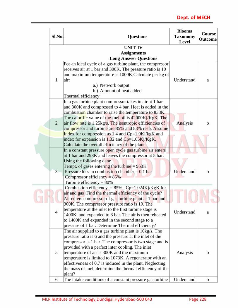
Dept. of MECH
MLR Institute of Technology,Dundigal,Hyderabad-500 043 Page 228
Sl.No. Questions
Blooms
Taxonomy
Level
Course
Outcome
UNIT-IV
Assignments
Long Answer Questions
1
For an ideal cycle of a gas turbine plant, the compressor
receives air at 1 bar and 300K. The pressure ratio is 10
and maximum temperature is 1000K.Calculate per kg of
air:
a.) Network output
b.) Amount of heat added
Thermal efficiency
Understand a
2
In a gas turbine plant compressor takes in air at 1 bar
and 300K and compressed to 4 bar. Heat is added in the
combustion chamber to raise the temperature to 833K.
The calorific value of the fuel oil is 42000Kj/KgK. The
air flow rate is 1.25kg/s. The isentropic efficiencies of
compressor and turbine are 85% and 83% resp. Assume
Index for compression as 1.4 and Cp=1.0Kj/kgK and
index for expansion is 1.32 and Cp=1.05Kj/KgK.
Calculate the overall efficiency of the plant
Analysis b
3
In a constant pressure open cycle gas turbine air enters
at 1 bar and 293K and leaves the compressor at 5 bar.
Using the following data:
Tempt. of gases entering the turbine = 953K
Pressure loss in combustion chamber = 0.1 bar
Compressor efficiency = 85%
Turbine efficiency = 80%
Combustion efficiency = 85% , Cp=1.024Kj/KgK for
air and gas Find the thermal efficiency of the cycle?
Understand b
4
Air enters compressor of gas turbine plant at 1 bar and
300K. The compressor pressure ratio is 10. The
temperature at the inlet to the first turbine stage is
1400K, and expanded to 3 bar. The air is then reheated
to 1400K and expanded in the second stage to a
pressure of 1 bar. Determine Thermal efficiency?
Understand a
5
The air supplied to a gas turbine plant is 10kg/s. The
pressure ratio is 6 and the pressure at the inlet of the
compressor is 1 bar. The compressor is two stage and is
provided with a perfect inter cooling. The inlet
temperature of air is 300K and the maximum
temperature is limited to 1073K. A regenerator with an
effectiveness of 0.7 is induced in the plant. Neglecting
the mass of fuel, determine the thermal efficiency of the
plant?
Analysis b
6 The intake conditions of a constant pressure gas turbine Understand b

Dept. of MECH
MLR Institute of Technology,Dundigal,Hyderabad-500 043 Page 229
are 1 bar and 288K. The maximum pressure and
temperature in the cycle are 5 bar and 853K. What must
be the isentropic efficiency of the turbine if the overall
plant efficiency is 18%? Assume isentropic efficiency
of compressor is 80%. Take Cp=1.004KJ/kg K for air,
Cp=1.096Kj/KgK for gases and R=0.287KJ?KgK for
air and gas.
7
In a gas turbine plant, the compressor takes in air at 1
bar and 288K and compresses it to 4 bar. The fuel air
ratio is 0.0125 and the calorific value is 41870KJ/Kg.
The isentropic efficiencies of compressor and turbine
are 85% and 82% resp. Turbine inlet temperature is
1000K. Find the overall thermal efficiency?
Remember a
8
Air enters a compressor to open cycle, constant pressure
gas turbine plant at a pressure of 1 bar and a
temperature of 300K. The pressure ratio is 5 and the
turbine inlet temperature is 823K. Assume compressor
and turbine efficiencies to be 85%, determine thermal
efficiency of the plant, when a regenerator with 60%
effectiveness is used?
Understand a
9
The air enters a compressor of brayton cycle at 1 bar
and 288K.The turbine inlet temperature and pressure
are 923K and 4 bar. Assuming turbine efficiency=85%
and compressor efficiency=80%. Determine the
efficiency of the cycle
Evaluate e
10 What is Actual Gas turbine Cycle? Explain with PV and
TS diagram
Sl.No. Questions
Blooms
Taxonomy
Level
Course
Outcome
UNIT-V
Assignments
Short Answer Questions
1 Draw a neat sketch of Ram-jet engine? Understand a
2 Draw a neat sketch of pulse-jet engine? Analysis b
3 Classify rockets according to the type of propellant? Understand b
4 Classify rockets according to the number of motors? Understand a
5 Explain velocity of approach of air? Analysis b
6 What is "Ram effect" ? Understand b
7 Write the limitations of Ram-jet engine? Evaluate e
8 Write the limitations of pulse-jet engine? Remember a
9 When is the best performance of ram-jet engine
obtained? Understand a
10 Explain the process inside the combustion chamber
of "ram-jet engine"? Evaluate e
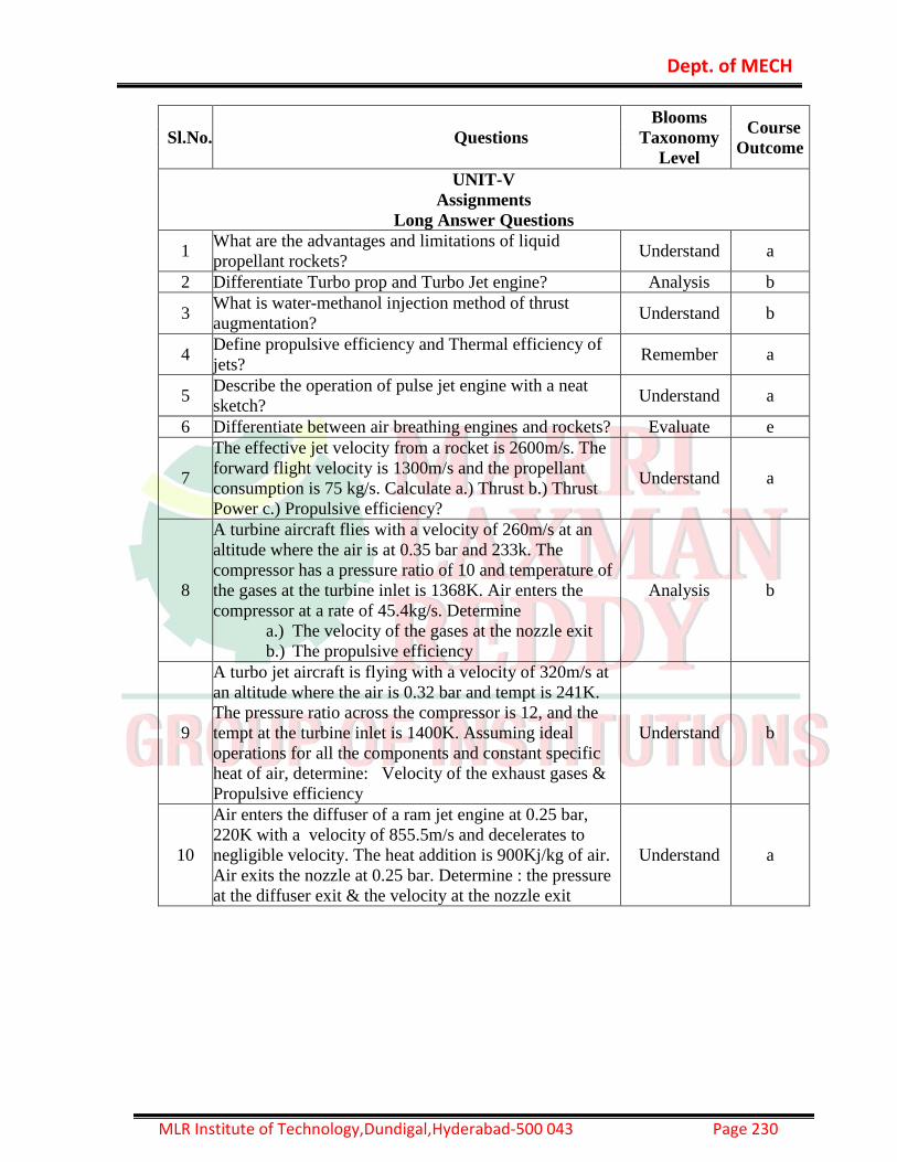
Dept. of MECH
MLR Institute of Technology,Dundigal,Hyderabad-500 043 Page 230
Sl.No. Questions
Blooms
Taxonomy
Level
Course
Outcome
UNIT-V
Assignments
Long Answer Questions
1 What are the advantages and limitations of liquid
propellant rockets? Understand a
2 Differentiate Turbo prop and Turbo Jet engine? Analysis b
3 What is water-methanol injection method of thrust
augmentation? Understand b
4 Define propulsive efficiency and Thermal efficiency of
jets? Remember a
5 Describe the operation of pulse jet engine with a neat
sketch? Understand a
6 Differentiate between air breathing engines and rockets? Evaluate e
7
The effective jet velocity from a rocket is 2600m/s. The
forward flight velocity is 1300m/s and the propellant
consumption is 75 kg/s. Calculate a.) Thrust b.) Thrust
Power c.) Propulsive efficiency?
Understand a
8
A turbine aircraft flies with a velocity of 260m/s at an
altitude where the air is at 0.35 bar and 233k. The
compressor has a pressure ratio of 10 and temperature of
the gases at the turbine inlet is 1368K. Air enters the
compressor at a rate of 45.4kg/s. Determine
a.) The velocity of the gases at the nozzle exit
b.) The propulsive efficiency
Analysis b
9
A turbo jet aircraft is flying with a velocity of 320m/s at
an altitude where the air is 0.32 bar and tempt is 241K.
The pressure ratio across the compressor is 12, and the
tempt at the turbine inlet is 1400K. Assuming ideal
operations for all the components and constant specific
heat of air, determine: Velocity of the exhaust gases &
Propulsive efficiency
Understand b
10
Air enters the diffuser of a ram jet engine at 0.25 bar,
220K with a velocity of 855.5m/s and decelerates to
negligible velocity. The heat addition is 900Kj/kg of air.
Air exits the nozzle at 0.25 bar. Determine : the pressure
at the diffuser exit & the velocity at the nozzle exit
Understand a

Dept. of MECH
MLR Institute of Technology,Dundigal,Hyderabad-500 043 Page 231
15. MACHINE TOOLS & METROLOGY LAB
Section A :
1. Measurement of lengths, heights, diameters by vernier calipers micrometers etc.
2. Measurement of bores by internal micrometers and dial bore indicators.
3. Use of gear teeth, vernier calipers and checking the chordal addendum and chordal height of
spur gear.
4. Machine tool “alignment test on the lathe.
5. Machine tool alignment test on milling machine.
6. Tool makers microscope and its application
7. Angle and taper measurements by Bevel protractor, Sine bars, etc.
8. Use of spirit level in finding the flatness of surface plate.
9. Thread measurement by Two wire/ Three wire method or Tool makers microscope.
10. Surface roughness measurement by Taly Surf.
11. Surface Wear Resistances Test using Electro Spark Coating Device.
Section B :
1. Introduction of general purpose machines -Lathe, Drilling machine, Milling machine, Shaper,
2. Planing machine, slotting machine, Cylindrical Grinder, surface grinder and tool and cutter
grinder.
3. Step turning and taper turning on lathe machine
4. Thread cutting and knurling on -lathe machine.
5. Drilling and Tapping
6. Shaping and Planing
7. Slotting
8. Milling
9. Cylindrical Surface Grinding
10. Grinding of Tool angles.

Dept. of MECH
MLR Institute of Technology,Dundigal,Hyderabad-500 043 Page 232
Machne Tools Experiments:
1. INTRODUCTION OF GENERAL PURPOSE OF MACHINES - Lathe machine, - Shaper machine, - Slotting machine, - Planning machine, - Drilling machine, - Boring machine, - Milling machine, - Grinding machine - Lapping machine - Honing machine - Broaching machine
2. LATHE OPERATIONS - Facing - Chamfering - Step turning - Taper turning - Plain turning - Knurling - Grooving - Thread cutting
3. DRILLING OPERATIONS -Drilling -Boring -Tapping 4. SHAPING AND PLANNING OPERATIONS 5. SLOTTING OPERATIONS 6. MILLING OPERATIONS -Vertical milling 7. GRINDING OPERATIONS
- Surface grinding

Dept. of MECH
MLR Institute of Technology,Dundigal,Hyderabad-500 043 Page 233
16. METROLOGY LAB
1. VERNIER CALIPERS
2. MICROMETER(OUTSIDE)
3. MICROMETER(INSIDE)
4. GEAR TOOTH MICROMETER
5. BORE GUAGE
6. SPIRIT LEVEL
7. OPTICAL BEVEL PROTRACTOR
8. TOOL MAKERS MICROSCOPE
9. SCREW THREAD MICROMETER
10. VERNIER HEIGHT GAUGE
11. MICROMETER DEPTH GAUGE
12. ALIGNMENT TEST ON DRILLING MACHINE
13. ALIGNMENT TEST ON MILLING MACHINE
14. ALIGNMENT TEST ON LATHEMACHINE

Dept. of MECH
MLR Institute of Technology,Dundigal,Hyderabad-500 043 Page 234
17. THERMAL ENGINEERING LAB
1. I.C. Engines Valve / Port Timing Diagrams
2. I.C. Engines Performance Test( 4 -Stroke Diesel Engines )
3. I.C. Engines Performance Test on 2-Stroke Petrol
4. Evaluation of Engine friction by conducting Morse test on 4-Stroke Multi cylinder Petrol Engine
5. Evaluate of engine friction by conducting motoring /retardation test on 4 stroke diesel Engine.
6. Heat balance on IC Engines.
7. Determination of A/F Ratio and Volumetric Efficiency on IC Engines.
8. Determine of Economical speed test for fixed load on 4-stroke Engine.
9. Determine optimum cooling water temperature on IC Engine
10. Dis-assembly / Assembly of Engines.
11. Performance test on Reciprocating Air-compressor unit.
12. Study of Boilers.