MIL-E-23765/2D(SH) - EverySpec
37
MIL-E-23765/2D(SH) 18 August 1987 SUPERSEDING MIL-E-23765/2C(SH) 17 June 1983 (See 6.4) MILITARY SPECIFICATION ELECTRODES AND RODS - WELDING, BARE, SOLID, OR ALLOYED CORED, LOW ALLOY STEEL This specification is approved for use within the Naval Sea Systems Command, Department of the Navy, and is available for use by all Departments and Agencies of the Department of Defense. 1. SCOPE 1.1 Scope. This specification covers low alloy steel solid bare welding electrodes, alloy cored bare welding electrodes and cut-length rods for use with gas metal-arc (GMA) and gas tungsten-arc (GTA) welding processes. This specifi- cation also covers low alloy steel solid or alloy cored bare welding electrodes for use with submerged-arcwelding (SAW) processes employing a neutral granular flux, or for use with GMA processes. 1.2 Classification. 1.2.1 Electrode and rod types, forms and sizes. Electrodes and rods shall be provided in the types specified in table I in forms 3a, 3b, 3c, 3d, 3e, 4, and 6 with sizes as specified in MIL-E-23765 and table 11 herein. 1.2.2 Neutral granular flux types. Neutral granular flux for as-welded or stress relieved SAW applications shall be provided in the types qualified (see 3.2.3). Beneficial comments (recommendations,additions, deletions) and any pertinent data which may be of use in improving this document should be addressed to: Commander, Naval Sea Systems Command, SEA 55Z3, Department of the Navy, Washington, DC 20362-5101 by using the self-addressed StandardizationDocument Improvement Proposal (DD Form 1426) appearing at the end of this document or by letter. AMSC N/A FSC 3439 DISTRIBUTION STATEMENT A Approved for public release; distribution unlimited Downloaded from http://www.everyspec.com
-
Upload
khangminh22 -
Category
Documents
-
view
1 -
download
0
Transcript of MIL-E-23765/2D(SH) - EverySpec

MIL-E-23765/2D(SH)18 August 1987SUPERSEDINGMIL-E-23765/2C(SH)17 June 1983(See 6.4)
MILITARY SPECIFICATION
ELECTRODES AND RODS - WELDING, BARE, SOLID, ORALLOYED CORED, LOW ALLOY STEEL
This specification is approved for use within the Naval Sea SystemsCommand, Department of the Navy, and is available for use by allDepartments and Agencies of the Department of Defense.
1. SCOPE
1.1 Scope. This specification covers low alloy steel solid bare weldingelectrodes, alloy cored bare welding electrodes and cut-length rods for use withgas metal-arc (GMA) and gas tungsten-arc (GTA) welding processes. This specifi-cation also covers low alloy steel solid or alloy cored bare welding electrodesfor use with submerged-arcwelding (SAW) processes employing a neutral granularflux, or for use with GMA processes.
1.2 Classification.
1.2.1 Electrode and rod types, forms and sizes. Electrodes and rods shallbe provided in the types specified in table I in forms 3a, 3b, 3c, 3d, 3e, 4,and 6 with sizes as specified in MIL-E-23765 and table 11 herein.
1.2.2 Neutral granular flux types. Neutral granular flux for as-weldedor stress relieved SAW applications shall be provided in the types qualified(see 3.2.3).
Beneficial comments (recommendations,additions, deletions) and any pertinentdata which may be of use in improving this document should be addressed to:Commander, Naval Sea Systems Command, SEA 55Z3, Department of the Navy,Washington, DC 20362-5101 by using the self-addressed StandardizationDocumentImprovement Proposal (DD Form 1426) appearing at the end of this document orby letter.
AMSC N/A FSC 3439DISTRIBUTION STATEMENT A Approved for public release; distribution unlimited
Downloaded from http://www.everyspec.com

MIL-E-23765/2D(SH)
u
i
o*
ol-l
eJ-l
0d.
0.-l
.
-
r-06
04.
04.
— — —
m0*
m0
e
m0
.u-l0
.m0
.
r)0
.— — — —
m 0m
.Ln
mvi
.
0u-im0
Inu-l
*
~
Cu0
0Q
.
Ac-$-l
*
0 in$4
.
003
.
700A
4-I
0ou0
No
*
U-)No
.
coo0
.
codu.!4 — — — —
‘Ndo
*Gt-du
— — uc3’CoCJ
Ino
.0co
.
Am
.
u-lu-l
o
&N
.—oco
.
7u-lN
..-(
(n
— — —0co
.
T’mN
.
—u-l
— — —coo
.ao
.m
.-i
— — —
y)
~co
— —
2
Downloaded from http://www.everyspec.com

MIL-E-23765/2D(SH)
TABLE II. Electrode form, size, and weight.
Electrode diameter Weigh~/Form (inches) (pounds)
3a All 1-1/2 and 2-1/2
3b All 10 or 15
3b All 25, 30, 35 or 44
3C All 25, 50, or 60
3d All 60 or 65
3e All 150 or 200
4 All 750 or less
6 All 10 or 50
l_/Tolerance on net weight shall be plus or minus 10 percent.
2. APPLICABLE DOCUMENTS
2.1 Government documents..
2.1.1 Specificationsand standards. The following specificationsand stan-dards form a part of this specification to the extent specified herein. Unlessotherwise specified, the issues of these documents shall be those listed in theissue of the Department of Defense Index of Specificationsand Standards (DoDISS)and supplement thereto, cited in the solicitation.
SPECIFICATIONS
FEDERALBB-O-925 -
MILITARYMIL-s-16216 -
MIL-A-18455 -MIL-S-23194 -MIL-E-23765 -
MIL-S-24238 -MIL-S-24645 -
Oxygen, Technical, Gas and Liquid.
Steel Plate, Alloy, Structural, High Yield Strength(HY-80 and HY-1OO).
Argon, Technical.Steel Forgings, Carbon and Low Alloy.Electrodes and Rods - Welding, Bare, Solid andAlloyed Cored,“GeneralSpecification for.Steel Plate, Carbon and Low Alloy.Steel Plate, Sheet, or Coil Age-Hardening Alloy,Structural, High Yield Strength (HSLA-80).
3
I
Downloaded from http://www.everyspec.com

MIL-E-23765/2D(SH)
STANDARDS
FEDERALFED-STD-151 - Metals; Test Methods.
MILITARYMIL-STD-147 - Palletized Unit Loads.MIL-STD-271 - Requirements for Nondestructive Testing Methods.MIL-STD-2149 - Standard Procedures for Explosion Testing Ferrous
and Non-Ferrous Metallic Materials and Weldments.
2.1.2 Other Government publications. The following other Governmentpublications form a part of this specification to the extent specified herein.Unless otherwise specified, the issues shall be those in effect on the date ofthe solicitation.
PUBLICATIONS
NAVAL SEA SYSTEMS COMMAND (NAVSEA)0900-LP-O03-8000 - Metals, Surface Inspection Acceptance Standards.0900-LP-003-9000- Radiographic Standards for Production and
Repair Welds.
(Copies of specifications, standards and publications required by con-tractors in connectionwith specific acquisition functions should be obtainedfrom the contracting activity or as directed by the contracting activity.)
2.2 Other publications. The following documents form a part of this speci-fication to the extent specified herein. Unless otherwise specified, the issues ●of the documents which are DoD adopted shall be those listed in the issue of theDoDISS specified in the solicitation. Unless otherwise specified, the issues ofdocuments not listed in the DoDISS shall be the issue of the nongovernment docu-ments which is current on the date of the solicitation.
AMERICAN SOCIETY FOR TESTING AND MATERIALS (ASTM)A 302 - Standard Specification for Pressure Vessel Plates, Alloy
Steel, Manganese-Molybdenumand Manganese-MolybdenumNicke1. (DoD adopted)
A 508 - Standard Specification for Quenched and Tempered Vacuum-Treated Carbon and Alloy Steel Forgings for PressureVessels. (DoD adopted)
A 533 - Standard Specification for Pressure Vessel Plates, AlloySteel, Quenched and Tempered, Manganese-MolybdenumandManganese-Molybdenum-Nickel. (DoD adopted)
A 710 - Standard Specification for Low-Carbon Age-HardeningNickel-Copper-Chromium-Molybdenum-Columbiumand Nickel-Copper-ColumbiumAlloy Steels.
E 83 - Standard Practice for Verification and Classification ofExtensometers. (DoD adopted)
Downloaded from http://www.everyspec.com

MIL-E-23765/2D(SH)
.
ASTM - ContinuedE 604 - Standard Test Method for Dynamic Tear Testing of Metallic
Materials. (DoD adopted)E 1010 - Standard Practice for Preparation of Disk Specimens of
Steel and Iron for SpectrochemicalAnalysis by Remelting.
(Application for copies should be addressed to the American Society forTesting and Materials, 1916 Race Street, Philadelphia, PA 19103.)
AMERICAN WELDING SOCIETY (AWS)A4.3 - Procedures for Determination of Diffusible Hydrogen Content
of Martensitic, Bainitic and Ferritic Weld Metal Producedby Arc-Welding.
B4.O - Standard Methods for Mechanical Testing of Welds.(DoD adopted)
(Application for copies should be addressed to the American Welding Society,Inc., 550 NW LeJeune Road, P.O. Box 351040, Miami, FL 33135.)
UNIFORM CLASSIFICATION COMMITTEE AGENTUniform Freight ClassificationRatings, Rules and Regulations
(Application for copies should be addressed to the Uniform ClassificationCommittee Agent, Tariff Publication Officer, Room 1106, 222 South Riverside Plaza,Chicago, IL 60606.)
(Nongovernment standards and other publications are normally availablefrom the organizations which prepare or which distribute the documents. Thesedocuments also may be available in or through libraries or other informationalservices.)
2.3 Order of precedence. In the event of a conflict between the text ofthis specificationand the references cited herein (except for associated detailspecifications,specification sheets or MS standards), the text of this specifi-cation shall take precedence. Nothing in this specification,however, shallsupersede applicable laws and regulations unless a specific exemption has beenobtained.
3. REQUIREMENTS
3.1 Electrodes and rods provided under this specification shall be in accor-dance with MIL-E-23765 and as specified herein. Neutral granular flux providedunder this specification shall be in accordance with the requirements specifiedherein.
3.2 MIL-types.
3.2.1 Basic MIL-type. Basic MIL-type electrodes and rods may have eithera clean bright finish or a uniform continuous well-bonded smoothly drawn coppercoating on a clean surface. Diameters 3/32 inch and smaller may be coated withother types of rust preventatives provided such coatings do not impair usabilityof the electrodes or the quality or soundness of weld metal deposits.
5“
Downloaded from http://www.everyspec.com

MIL-E-23765/2D(SH)
3.2.2 Special MIL-type with suffix RC. Special MIL-type electrodes and
rods, designated by the suffix RC (see footnote 2 of table 1), shall not becopper coated but may have either a bright finish or a special protective coatingprovided the coating does not impair usability of the electrodes or rods or thequality and soundness of the weld metal deposits.
3.2.3 MIL-type with suffix F. For as-welded or stress relieved applica-tions, the MIL-type designation of a qualified flux consists of the MIL-typedesignation of the electrode it was qualified with, plus the suffix F (forexample, MIL-1OOS-1F).
3.2.4 Special MIL-120 types with suffix X. MIL-120 electrodes, rods oralloy cored electrodes qualified using alternating current (at) (see footnote 1of table 111) shall be designated by the suffix X.
3.2.5 Special MIL-1OO and MIL-120 types with suffix SR. MIL-1OO andMIL-120 electrodes, rods or alloy cored electrodes tested in the stress relievedcondition (see 3.401) shall be designated with the suffix SR.
3.3 Chemical composition. Chemical composition of unwelded electrodes androds and weld metal deposited in an inert atmosphere using the GTAW process byalloy cored electrodes shall be in accordance with table 1.
3.4 Mechanical properties. The mechanical properties of weld metal inthe as-welded condition shall be in accordance with table III. The mechanicalproperties of weld metal in the stress relieved condition shall be in accordancewith table IV.
6
Downloaded from http://www.everyspec.com

MIL-E-23765/2D(SH)
5
aN
rasocm2!
●
g
T’*I$4cd
f!“
.
oau)30
i!&:Ill@@na)u
alm&@’uggcm
:Oz000-N-N0!+
ouOz000.N“!20!+4
7
Downloaded from http://www.everyspec.com

MIL-E-23765/2D(SH)
~/ The test assembly welding heat input for each lot of material being testedshall be:
t
(a) One test assembly at 110,000 joules per inch minimum for qualityconformance inspection.
(b) One test assembly at 55,000 to 65,000 joules per inch and anothertest assembly at 110,000 joules per inch minimum for schedule Aqualification testing.
(c) One Lest assembly at 110,000 joules per inch minimum for schedule Bqualification testing. Any appropriate welding heat input shall beused for the root layer and minor repair deposited by the GMA, GTAand SAW processes.
6/ Transverse side bend specimens shall be tested as specified in AWS B4.O. The—specimens after bending shall have no cracks or other indications greaterthan 1/8 inch in any direction on a convex surface. Tears less than 1/8 inch ‘on the corner of the bend specimen are acceptable.
~/ The average value of five tests shall be equal to or greater than the minimumaverage value specified. No two specimens shall have values below theminimum average specified. One specimen can have value of 10 foot-poundsbelow the minimum average specified.
8/ The average value of two tests shall be equal to or greater than the minimum—average value specified. One specimen can have a value of 50 foot-poundsbelow the minimum average specified.
9/ The average value of two tests shall be equal to or greater than the minimum—average value specified. One specimen can have a value of 25 foot-poundsbelow the minimum average specified.
10/ The tests shall be conducted at zero degrees Fahrenheit (“F) in accordance— awith MIL-STD-2149 and in accordance with the following. Two crack startertests shall be conducted. The four bulge tests shall be conducted onlywhen required by NAJJSEA. Performance is considered satisfactory providedthe following conditions are met:
(a) Crack starter.
First shot:Crack starter bead must crack.Percent reduction in thickness obtained for information only.No piece shall be thrown out of material being tested.NO through-thicknesscracks shall be present.No cracks shall extend into hold-down area (see note).
Second shot:Percent reduction in thickness obtained for information only.No piece shall be thrown out of material being tested.Through-thickness cracks are acceptable.No cracks shall extend into hold-down area (see note).
(b) Bulge.
First shot:Percent reduction in thickness obtained for information only.No piece shall be thrown out of material being tested.No through-thicknesscracks shall be present.No cracks shall extend into hold-down area (see note).
Downloaded from http://www.everyspec.com

MIL-E-23765/2D(SH)
(c)
Second shot:Percent reduction in thickness obtained for information,3 percent reduction per shot is expected.
No piece shall be thrown out of material being tested.No through-thicknesscracks shall be present.No cracks shall extend into hold-down area (see note).
Additional shots: Shots shall continue until a minimum of 10 percentreduction in thickness is obtained on one or both plates or eitherside of the weld. The performance is considered satisfactory providedthe following conditions are met:
No piece shall be thrown out of material being tested.Through-thickness cracks are acceptable.No cracks shall extend into hold-down area (see note).Shots shall be discontinuedwhen cracks go into the hold-downarea, a through-thicknesscrack occurs, or if the reductionin thickness requirements are met.
NOTE: The bulge area is defined as that plate over the diehole (9-inch radius)plus the rounded outside corners (3-inch radius) plus 1/2 inch for a totalcircle diameter of 25 inches. The hold-down area is defined as the areaoutside of this circle.
11/ The test assembly welding heat input for each lot of material being qualifi-—cation tested or quality conformance inspected shall be 55,000 to 65,000joules per inch.
12/ All conformance retests shall be reported to the user, including original—test results and explanation of the cause for retest.
13/ Alloy cored electrodes are designated by suffix C.—
TAME IV. Mechanical properties for stress relieved welds..!/
0.2 percentUltimate offset Percenttensile yield elongation Average Charpystrength strength 1.4 or V-notch impact
MIL- (minimum (minimum 2 inches~
energy minimum Guidedtype&l lb/in2) lb/in2) (minimum) ft-lb)~ at 10”F bend
80S-1,80S-lF,80S-2,80S-2F, 80,000 50,000 20 30 ~/and80S-3
loos-l 90,000 80,000 18 35 ~/loos-2
120s-1 ~/ ~/ ~/ ~/ ;/120s-2
I
See footnotes on next page.
9
Downloaded from http://www.everyspec.com

MIL-E-23765/2D(SH)
Individual impact test results shall be reported. The test results used indetermining each average Charpy V-notch impact energy value shall contain nomore than one observation below the value as specified in table IV and that ●observation shall not be more than 5 foot-pounds below the value indicated inaccordance with table IV. Percent shear fracture shall be reported.Guided bend test specimens shall be tested as specified in AWS B4.O. Thespecimens after bending shall have no cracks or other indications greaterthan 1/8 inch in any direction on a convex surface. Tears less than 1/8inch on the corner of the bend specimen are acceptable.The required mechanical properties after stress relief on 120S type weld metalshall be as specified (see 6.2). The electrode types shall be tested usingdc reverse polarity or ac for SAW, and dc straight polarity for GTA.See 3.4.1.Alloy cored electrodes are designated by suffix C.
3.4.1 Stress relief. Type 80S weld metal test plates and, when specified(see 6.2), types 100S and 120S weld metal plates shall be stress relieved at1125: 25°F for one of the following periods as specified (see 4.2 and 6.2):(a) for 50 hours minimum or greater as specified (see 6,2) or (b) held attemperature for 1 hour per inch of weld thickness (for weld thicknesses lessthan 1 inch, the minimum holding time shall be proportional to the weld thick-ness but shall be not less than 30 minutes). The test plates treated by eithermethod (a) or (b) shall be cooled at a maximum rate of 10°F per hour from thestress relief temperature to 600”F.
3.5 Soundness. Welds deposited with type 100S-1, 100S-2, 120S-1 and120S-2 electrodes shall be in accordance with NAVSEA 0900-LP-O03-8000formagnetic particle inspection. Radiographs or welds deposited with all typesof electrodes shall be in accordance with class I production welds as specified ●in NAVSEA 0900-LP-003-9000.
3.6 Diffusible hydrogen. The diffusible hydrogen levels in millilitersper 100 grams (mL/100 grams) of deposited weld metal shall not exceed the valuesspecified in table V.
Downloaded from http://www.everyspec.com

MIL-E-23765/2D(SH)
aTABLE V. Diffusible hydrogen values.
I I 1Welding Maximum Maximum single
MIL-type process average value
loos-l 4.0 4.8120s-1
loos-l SAW 6.0 7.2120s-1
loos-2 ‘ 2.0 2.8120s-2
loos-2 SAW 3.0 3.8120s-2
1OOS-1F SAW 6.0 7.2120S-lF
1OOS-2F SAW 3.0 3.8120S-2F
i 1 1
3.7 .MoisEurecontent of MIL-1OO and MIL-120 type fluxes. The total water
●content (both hydroscopic and absorbed) of MIL-1OOS-1F, MIL-1OOS-2F, MIL-120S-lFor MIL-120S-2F flux shall not exceed 0.15 percent by weight.
4. QUALITY ASSURANCE PROVISIONS
4.1 The quality assurance provisions shall be as specified in MIL-E-23765and as specified herein.
4.2 Qualificationtests. Qualification tests shall be in accordance withtable VI. The test sample of electrodes or flux selected in accordance withMIL-E-23765 shall be used for these tests.
11
Downloaded from http://www.everyspec.com

MIL-E-23765/2D(SH)
u
x
x x
x I I I
x I
c-dalu
.2a
.t-n
—
Gdalu
2G
.+’—
—
—
—
—
—
—
—
o
:sau
wo
-0Gal
um
m
socuo0u-l
aJ
$4
12
Downloaded from http://www.everyspec.com

MIL-E-23765/2D(SH)
U
mu
\or-lull so
t
x
xx
T xx
x
-t-
*
x x
* x
x
$!:usrn’e
13
Downloaded from http://www.everyspec.com

MIL-E-23765/2D(SH)
c-dalid
2’1%
I.-1 mQccco-+4$42.eJr-. .Uu
WCL4l-l.,+3aJMLITII?.+a)ccnL1/=t%-s
R
—
x
x
—
—x
x
IJlaluw-dS>cu.+04J4Jz
x
.
x
x
—
— L1xalcwo
0(o4.)
x
1’4
Downloaded from http://www.everyspec.com

MIL-E-23765/2D(SH)
Use SAW with a qualified electrode to qualify these neutral granular fluxtypes for the stress relieved condition.
Use GMA with a shielding gas to qualify this electrode type for the stressrelieved condition.
The electrode sizes and welding processes used for qualification testingshall be in accordance with 4.2.2 herein.
Use SAW with a qualified electrode to qualify these neutral granular fluxtypes for the as-welded condition.
And notes applying thereto.Alloy cored electrodes are designated by suffix C. The brand name of fluxused in Schedule A and B testing shall be specified in the qualificationtest reports.
Not applicable to Form 6.
4.2.1 MIL-80S-1, MIL-80S-lF, MIL-80S-2, MIL-80S-2F and MIL-80S-3. MIL-80S-1and MIL-80S-2 electrodes shall be deposited by the SAW process in combinationwith MIL-80S-lF or MIL-80S-2F flux respectively. MIL-80S-3 electrodes shall bedeposited by the GMA or GTA welding process. Weldment shall be tested in thestress relieved condition in accordance with 3.4.1 for both the 50-hour andl-hour holding times.
4.2.2 MIL-1OOS-1, MIL-1OOS-2, MIL-120S-1, and MIL-120S-2. For MIL-1OOS-1,MIL-1OOS-2, MIL-120S-1 and MIL-120S-2 electrodes welding parameters shall be,inaccordance with figure 3 and table VII as specified below. The welding positionand welding process shall be according to the electrode size tested as foll”ows:
●TABLE VII. Welding parameters.
Qualificationelectrode size Welding Size range qualified
(inches) process Position (inches)
0.045 Pulsed-arc Vertical up 0.020 - 0.045
1/16 Spray-arc Flat 0.052 - 5/64
1/8 SAW Flat 3/32 - 1/4
Qualification of each of the above sizes will qualify all of the electrodes ineach of the size ranges specified above. Weldment shall be tested in the as-welded condition without any post weld soak.
4.2.3 MIL-1OOS-1F, MIL-1OOS-2F, MIL-120S-lF and MIL-120S-2F. MIL-1OOS-1F,MIL-1OOS-2F, MIL-120S-lF and MIL-120S-2F flux types shall be used in combinationwith a correspondingMIL-type electrode to deposit weld metal by the SAW process,and the weldments tested in the as-welded condition.
15
Downloaded from http://www.everyspec.com

MIL-E-23765/2D(SH)
4.2.3.1 Sampling for qualification of flux packagin~ The flux used toqualify flux packaging shall be from a lot sample package as defined inMIL-E-23765 and the following: ●
(a) The sample package shall be placed next to anotherpackage of the same type.
(b) The stack of packages shall be sprayed with waterfor not less than five minutes using a shower headattached to a garden hose. All exposed surfacesshall be wetted. The sample package shall be placedon top of the other packagej wet side down.
(c) The stack shall be still air dried at room temperaturefor a period of seven daysO
(d) All the flux from the sample package shall be mixed,then subdivided by successive quartering and by acleast four passes through a riffle into the amountof flux required for the water content test of 4.7herein. The flux water content shall meet therequirements of 3.7 herein.
(e) Any change in package material, type or method ofconstruction shall be requalified. One retest ispermitted. Results of both tests shall be reported.
4.3 Quality conformance inspection. Quality conformance inspection testsshall be performed in accordance with table VIII. The test samples of electrodesor rods selected in accordance with MIL-E-23765 shall be used for the testsspecified in table VIII. The test sample of neutral granular flux selected inaccordance with MIL-E-23765 shall be used for the Lests specified in table VIII.When required, the stress relief treatment shall be in accordance with 3.4.l(a) ●or 3.4.l(b) as specified (see 6.2). Type 100S and 120S electrode lots meetingacceptance requirements in the stress relieved condition shall be identified withthe suffix %R’O.
16
Downloaded from http://www.everyspec.com

MIL-E-23765/2D(SH)
●
—
.
x
—
I I x Ix I Ix I
—
x
—
I x
—
x I—
xt
a
17
Downloaded from http://www.everyspec.com

MIL-E-23765/2D(SH)
!
u.c
.+
l-l
Q
:w+ua)mmUJal
.
Downloaded from http://www.everyspec.com

MIL-E-23765/2D(SH)
4.3.1 Bare solid electrodes.
● 4.3.1.1 Lot. For purposes of sampling and qualitya lot of elect=es or rods shall be the quantity of oneproduced as specified in MIL-E-23765.
conformance inspection,size and type alloy
4.3.1.2 Welding precess. Unless otherwise specified (see 6.2), test weld-ments shall be made using the following welding processes according to electrodesize:
Electrode size rangeinch Welding process and position
0.020 through 0.045 Pulsed-arc GMA in vertical position0.052 through 5/64 Spray-transferGMA in flat position3/32 through 1/4 SAW in flat position
4.3.2 Alloy cored electrodes.
4.3.2.1 Lot. For purposes of sampling and quality conformance inspection,a lot of alloy=red electrodes shall be the quantity of one size and type asspecified in MIL-E-23765.
4.3.2.2 Welding process. Test weldments shall be made using the SAW processin the flat position using the same brand name flux as was used in qualificationtesting.
4.3.3 Flux.
4.3.3.1 Lot. For purposes of sampling and quality conformance, a lot shallbe as defined in MIL-E-23765.
4.3.3.2 Welding precess. Test weldments shall be made in combination witha correspondingMIL-type electrode using the SAW process in the flat position.
4.3.4 Lot sampling for diffusible hydrogen. Every lot of material offeredfor acceptance under this specification, except MIL-80 types, shall be tested fordiffusible hydrogen content in accordance with 4.6 herein.
4.4 Base metal. Unless otherwise specified (see 6.2), the base metal steelused for the tests required herein shall be in accordance with table IX.
19
Downloaded from http://www.everyspec.com

MIL-E-23765/2D(SH)
TABLE IX. Base metal requirements.
l’41L-type&l Base metal
80S-1, 80S-2, NiCr-Mo steel in accordance with MIL-S-231!34,Or 80S-3 composition A, ASTM A 508, class 2, or
equivalent orMn-Ni-Mo steel in accordance with MIL-S-24238,composition A9 ASTM A 302, ASTM A 533, grade Bor C, class 19 or equivalent
~/~oos_l ~/Hy-80 steel in accordance with MIL-s-16216
1OOS-IF
~/~oos_2 ~/Hy-80 steel in accordance with MIL-s-16216 or
100S-2F HSLA-80 in accordance with MIL-S-24645 whenspecified (see 6.2).
120s-1 ~/HY-100 steel in accordance with MIL-S-16216 or120S-lF HSLA-1OO in accordance with MIL-S-24645 when120s-2 specified (see 6.2).120S-2F
1/ For quality conformance testing in the stress relieved condition to—the requirements as specified in.table IV, other base metal steelsmay be specified (see 6.2).
2/ For quality conformance testing, if specified (see 6.2), MIL-S-24645 or—ASTM A 710 grade A steel may be specified for a second test weldmentin addition to the HY-80 steel test weldment required (see 6.2).
~/ These grades of steel are required (see figures 1 through 3) when dynamictear tests are to be conducted. Steel in the as-rolled condition asspecified in MIL-S-16216 may be used as shown on figure 3 for qualityconformance tests~ when dynamic tear tests are not being conducted.
4.5 Explosion bulge.
4.5.1 Welding parameters. Fabrication of the weldments shall be as follows:
(a) The base plate shall be as specified in table IX.(b) Dimensions of the test assemblies shall be as specified in
MIL-STD-2149.(c) The weldments shall be fabricated using the welding position
and wire diameter specified in 4.2.2 herein. The number ofweldments required shall be in accordance with footnote 10of table 111.
(d) The preheat and interpass temperature shall be 250~25°F.(e) The welding-heat input shall be as specified in notes to
table 111.
20
Downloaded from http://www.everyspec.com
MIL-E-23765/2D(SH)
.
..
1I~I
I
I
IIII
I
(f) Peening of weld beads shall not be permitted.(g) The test assembly shall be prepared by using welding sequence
and techniques recommended by the manufacturer which shall bereported.
(h) The joint surface shall not be clad or buttered.(i) Welding may be continuous except for interpass cooling. No
postweld heat treatments shall be employed. Time delay perpass beyond that necessary for interpass cooling shall bereported.
4.5.2 The two crack starter prolongations shall be as specified inMIL-STD-2149 and will be tested by the Naval Sea Systems Command (NAVSEA) inaccordance with schedule B of table VI.
4.6 Diffusible hydrogen test.
4.6.1 Procedure. The diffusible hydrogen test shall be performed in accor-dance with AWS A4.3.
4.6.2 Acceptance criteria. Material shall meet the requirements of 3.6.
4.6.3 Retest. If results from the first test fail to meet the requirementsof 3.6, one retest involving twice the number of specimens originally requiredmay be permitted. The results of all tests shall comply with 3.6. The retestspecimens shall be made using material from the same sample as the initial test.If the retest also fails to meet the requirements of 3.6, the material shall berejected. The supplier shall inform in writing all agencies having procured lotsof material delivered since the last successfully tested lot of the identity ofthe intervening lots.
4.7 Flux total water content. The total water content (both hydroscopicand absorbed) shall be determined as specified on figure 4 and the notes per-taining thereto.
4.8 Chemical analysis. Chemical analysis shall be performed as speci-fied in MIL-E-23765. The chemical analysis sample of alloy cored productsshall be melted using the GTAW process in an inert atmosphere in accordancewith ASTM E 1010 or other approved technique.
4.9 Certification of quality conformance. A certification of qualityconformance shall be furnished with each lot of material offered for acceptance.The certification shall include quantitative results of specified chemical andmechanical tests, and qualitative results of nondestructive tests on the lot.The minimum quality conformance test result data required shall be in accordancewith figure 5 and may be prepared in the format shown. The cause for any retestshall be reported for information and the results of all tests shall be reported.For alloy cored products only, the certification shall report the brand name offlux used in qualification testing.
4.10 Inspection of packaging. Sample packages and packs, and the inspec-tion of the preservation-packaging,packing and marking for shipment and storageshall be in accordance with the requirements of section 5 and the documentsspecified therein.
I
21
Downloaded from http://www.everyspec.com

MIL-E-23765/2D(SH)
5. PACKAGING
5.1 Preparation for delivery of electrodes. Preparation for delivery ofelectrodes shall be as specified in MIL-E-23765.
5.2 Preparation for delivery of flux. Preparation for delivery of fluxshall be as specified in MIL-E-23765.
5.2.1 Packing. Welding flux shall be packed in containers that meet orexceed the following requirements:
(a) Containers shall comply with the Uniform Freight ClassificationRules or other carrier regulations applicable to the mode oftransportation.
(b) Containers shall ensure safe delivery, acceptance at destinationand they shall protect the stability of the flux during storagein accordance with 3.7 herein.
(c) Containers shall be qualified in accordance with 4.2.3.1 herein.
5.2.1.1 Palletization. When specified (see 6.2), bags and drums shall bepalletized for shipment in accordance with MIL-STD-147.
5.2.2 Markin& Flux containers shall be marked as specified inMIL-E-23765.
5.2.3 Use of polystyrene (loose-fill)material. The use of polystyrene(loose-fill)material for packing applications such as cushioning, filler anddunnage is prohibited.
6. NOTES
6.1 Intended use.
6.1.1 General. This specification is intended to cover low alloy steelsolid bare welding electrodes and rods and alloy cored bare welding electrodesfor depositing weld metal, that in the as-welded condition meets the mechanicalproperties specified herein when welded on the applicable base metals as speci-fied in table IX using GMA, GTA, and SAW processes. This specification also isintended to cover low alloy steel solid bare welding electrodes for depositingweld metals that in the stress-relievedcondition meets the mechanical propertiesspecified herein when welded on the applicable base metals as specified in tableIX using either SAW welding processes employing a suitable neutral granular fluxor GMA and GTA welding processes with a suitable shielding gas. MIL-types 100S-1,100S-2, 120S-1 and 120S-2 or 1OOS-1F, 1OOS-2F, 120S-lF and 120S-2F, are intendedonly for as-welded applications, If they are conformance tested in the stress-relief condition and bear the SR suffix~ they may be used for stress-reliefapplications as well.
●
6.1.1.1 MIL-type 80S-1, 80S-2, and 80S-3. MIL-type 80S-1 and 80S-2 elec-trodes are suitable for welding MIL-S-23194, composition A steels; MIL-S-24238,composition A steels; ASTM A 508, class 2 or 3 steels; and ASTM A 533 or A 302steels using the SAW process. MIL-type 80S-3 is suitable for welding the samesteels using the GMA and GTA processes.
22
Downloaded from http://www.everyspec.com

MIL-E-23765/2D(SH)
6.1.1.2 Type MIL-1OOS-1. Type MIL-1OOS-1 electrode is suitable for weldingHY-80 steel.
6.1.1.2.1 Type MIL-1OOS-2. Type MIL-1OOS-2 electrode is suitable for weld-ing HY-80 steel, especially for approved reduced preheat applications.
6.1.1.3HY-1OO steel.
6.1.1.4HY-1OO steel,
6.1.1.5
Type MIL-120S-1. Type MIL-120S-1 electrode is suitable for welding
Type MIL-120S-2. Type MIL-120S-2 electrode is suitable for weldingespecially for approved reduced preheat application.
~pes MIL-1OOS-1F, MIL-1OOS-2F, MIL-120S-lF and MIL-120S-2F.MIL-1OOS-1F, MIL-1OOS-2F, MIL-120S-lF and MIL-120S-2F are the designations ofneutral granular flux to be used with the corresponding type of weld wire.
6.1.1.6 Special MIL-type with suffix RC. Restricted copper electrodesand rods will be used when specified (see 6.2 and table I).
6.1.1.7 Special types MIL-120S-lX and MIL-120S-2X. MIL-120S-lX andMIL-120S-2X electrodes are suitable for welding HY-1OO steel with the SAWprocess using ac current only.
6.1.1.8 MIL-types with suffix C. MIL-types with suffix C designate alloycored electrodes. Only the specific brand name of flux used during qualifica-tion and quality conformance testing is suitable for welding with alloy coredelectrodes to this specification.
6.2 Ordering data. Electrodes or flux intended for stress-relief applica-tions shall be so specified in the acquisition documents. Acquisition documentsshould also specify the following in addition to the ordering data required inMIL-E-23765:
(a) Whether the copper content should be restricted (see table Iand 6.1.1.6).
(b) The required mechanical properties for type MIL-120S-1 testwelds which have been stress-relieved (see footnote 3 totable IV).
(c) Time at the stress relief temperature (see 3.4.1 and 4.3).(d) Whether type 100S or 120S weld metal test plates should be
tested for conformance with stress-relievedrequirements(see 3.4.1, note 6 to figures 1 and 2).
(e) Whether a lot of electrodes under 3/32-inch diameter should bedeposited using the SAW process and tested in the as-weldedcondition (see footnote 4 of table VIII).
(f) Whether a lot of electrodes 3/32-inch diameter and larger shouldbe deposited using the GMA process and tested in the as-weldedcondition (see 4.3.1.2 and footnote 4 of table VIII).
23
Downloaded from http://www.everyspec.com

MIL-E-23765/2D(SH)
(g) Other base metal steel for use in testing in the stressrelieved condition~ if required (see 4.49 table IX andfootnote 1 thereof).
(h) Whether a second test weldment is required for qualityconformance Cesting in the as-welded condition (seefootnote 2 of table IX).
(i) Whether bags and drums shall be palletized for shipment(see 5.2.1.1).
(j) Whether figures 1 and 2 apply to types MIL-1OOS-1, 100S-2,120S-1, and 120S-2 (see note 10 to figure 1 and note 8 tofigure 2).
(k) Which sizes may be quality conformance tested using thesubmerged-arc process (see footnote 1 of figure 3).
(1) Whether test weldments shall be tested in the as-weldedcondition (see note 8 to figure 3).
6.3 Subject term (key word) listing.
Electrodes, weldingGas metal-arc (GMA)Gas tungsten-arc (GTA)Rods, weldingSteel, low alloySubmerged-arcwelding (SAW)
6.4 Changes from previous issue. Asterisks are not used in this revisionto identify changes with respect to the previous issue, due to the extensivenessof the changes.
Preparing activity:Navy - SH(Project 3439-N571)
24
Downloaded from http://www.everyspec.com

MIL-E-23765/2D(SH)
.
F ‘2”””1 -i+-
SH 7896A
●Test
classification Form Types
Qualification All All
~
Weld test details.
Diameter(inch) (ifch)
1/16 3/4
(i~ch)
1/2
Tensilespecimen(inch
diameter)
0.505
Weldingprocess
GMA andSAW
FIGURE 1. Weld joint for mechanical properties tests for typesMIL-80S-1, MIL-80S-2, and MIL-80S-3, MIL-80S-lF, andMIL-80S-2F.
25
Downloaded from http://www.everyspec.com

MIL-E-23765/2D(SH)
Notes to1.
2.
3.
4.
5.
6.
7.
8.
9.
10.
figure 1:Base plate shall be as specified in table IX and welded in flatposition.For MIL-80S types, the minimum preheat and maximum interpasstemperatures shall be 250 and 500°F, respectively. Shouldwelding be interrupted, the assembly may be allowed to coolin still air at room temperatures and prior to resumption ofwelding, the assembly shall be reheated to the minimum preheattemperature.
Welding currents and pass sequence shall be in accordance withsound welding practices> and as recommended by the manufacturer.Shielding gas shall be argon for GTA welding, and argon plus 2percent oxygen for GMA welded electrodes. Argon plus 5 percent C02may also be used for GMA welded electrodes. The argon and oxygenused for this test shall be in accordance with MIL-A-18455 andBE-O-925, respectively or equal. The neutral granular flux forthe SAW process shall be in accordance with 4.2.1 or 4.2.3 hereinwhich is consistent with MIL-type electrodes being tested.After completion of the weld, it shall be allowed to COO1, the weld
reinforcementbacking strip shall be removed flush with the baseplate, and the weld radiographer,as specified in MIL-E-23765.The backing strip may be removed by the air carbon arc gougingprocess. The weld shall be cut as shown resulting in a tensilecoupon suitable for 0.505 inch diameter specimen and a coupon ofsize sufficient for five Charpy V-notch specimens. No base metalshall be removed within 1/2 inch of the edges of the face of theweld by flame cutting. Only sawing or machining shall be used.Prior to machining specimens, type 80S test weldments and, whenspecified (see 6.2), types 100S and 120S test weldments shallbe stress relieved in accordance with 3.4.1.The tensile coupon shall be machined into a 0.505-inch tensilespecimen and tested as specified in MIL-E-23765. Center ofspecimen shall be approximately at T/2.
Five Charpy V-notch specimens shall be machined to dimensions asspecified in FED-STD-151. The notch shall be normal to the platesurface.Impact properties for five specimens shall be obtained at testtemperatures specified in table 111 or IV, as applicable, plusor minus 3°F.
When specified (see 6.2), figure 1 shall also apply to typesMIL-1OOS-1, MIL-1OOS-2, MIL-120S-1 and MIL-120S-2.
26
Downloaded from http://www.everyspec.com

MIL-E-23765/2D(SH)
.
1i
I
,
!
SH 5986A
Testclassification
Qualification
Qualityconformanceinspection
Qualityconformanceinspection
Types
All
All
All
Diameter(inch)
1/16
All
All
(i~ch)
3/4
1/2 to3/4
1/2
(i~ch)
1/2
1/41/2
1/4
Tensilespecimen(inch Welding
diameter) process
0.505 GMA andSAW
.358 GMA and
.505 SAW
.358 GTA
FIGURE 2. Weld joint for soundness and for mechanical testsfor types MIL-80S-1, MIL-80S-2, and MIL-80S-3,MIL-80S-lF, and MIL-80S-2F.
It
1027
Downloaded from http://www.everyspec.com
MIL-E-23765/2D(sH)
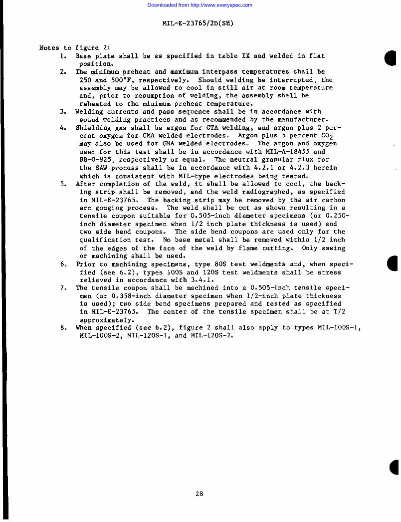
Notes to1.
2.
3.
4.
5.
figure 2:Base plate shall be as specified in table IX and welded in flatposition.The minimum preheat and maximum interpass temperatures shall be250 and 500*F, respectively. Should welding be interrupted, theassembly may be allowed to cool in still air at room temperatureandj prior to resumption of welding, the assembly shall bereheated to the minimum preheat temperature.
Welding currents and pass sequence shall be in accordance withsound welding practices and as recommended by the manufacturer.Shielding gas shall be argon for GTA welding, and argon plus 2 per-cent oxygen for GMA welded electrodes. Argon plus 5 percent C02may also be used for GMA welded electrodes. The argon and oxygenused for this test shall be in accordance with MIL-A-18455 andBB-O-925, respectively or equal. The neutral granular flux forthe SAW process shall be in accordance with 4.2.1 or 4.2.3 hereinwhich is consistent with MIL-type electrodes being tested.After completion of the weld, it shall be allowed to cool, the back-ing strip shall be removed, and the weld radiographer, as specifiedin MIL-E-23765. The backing strip may be removed by the air carbonarc gouging process. The weld shall be cut as shown resulting in atensile coupon suitable for 0.505-inch diameter specimens (or 0.250-inch diameter specimen when 1/2 inch plate thickness is used) andtwo side bend coupons. The side bend coupons are used only for thequalification test. No base metal shall be removed within 1/2 inchof the edges of the face of the weld by flame cutting. Only sawingor machining shall be used.Prior to machining specimens, type 80S test weldments and, when speci-fied (see 6.2), types 100S and 120S test weldments shall be stressrelieved in accordance with 3.4.1.The tensile coupon shall be machined into a 0.505-inch tensile speci-men (or 0.358-inch diameter specimen when l/2-inch plate thicknessis used); two side bend specimens prepared and tested as specifiedin MIL-E-23765. The center of the tensile specimen shall be at T/2approximately.When specified (see 6.2), figure 2 shall also apply to types MIL-lOOS-MIL-1OOS-2, MIL-120S-1, and MIL-120S-2.
1,
28
Downloaded from http://www.everyspec.com

MIL-E-23765/2D(SH)
SH 10572
I axmcwcIII .-- - --1- ---
1----
+ - -- 9 L ----t::I
*%-+&=-+:loM.++$=.-
LAWWW TZSTUCUUltT
, r+”
Jolar acommav 8Facmc9UUTION
Gas metal-arc welding~/, ~/ and~/
Electrode size 0.020 0.025 0.030 0.035 0.045 1/16 5/64(diameter-inch)
Wire feed speed(inches/minute)
55 Kj/in 2/ 2/ 2/ 2/ 165 230 165110 Kj/in ~/ ~/ ~1 430 250 230 165
Submerged-arcwelding~/ and~/
Electrode size ~/1/16 ~/5/64 3/32 1/8 5/32 3/16 -(diameter-inch)
55 Kj/in 400 400 525 500 500 ~/ -110 Kj/in!/ 500 500 600 600 600 ~/ -1
These sizes may be quality conformance tested by using the submerged-arcprocess when specified (see 6.2).Not specified. Supplier shall report Parameters used on the certification.Notes-3and 5 to figure 3 apply. ‘The specified parameters are required forMIL-1OO types only. Suppliers shall report parameters used in testingMIL-120 types on the certification.Supplier shall report power source used, average current and other controll-able parameters on the certification.Supplier,ahall report voltage, electrical stick out and,other controllableparameters on the certification.For alloy cored products, supplier shall report parameters used on the certi-fication.
FIGURE 3. Flat groove-weld metal test for MIL-1OOS-1, MIL-100S-21MIL-120S-1 and MIL-120S-2 electrodes, or MIL-1OOS-1F,MIL-1OOS-2F, MIL-120S-lF or MIL-120S-2F flux.
29
Downloaded from http://www.everyspec.com

MIL-E-23765/2D(SH)
Notes to figure 3:1. Base plate shall be as specified in table IX.2. The preheat and interpass temperature shall be 250 ~ 25”F, except for ●
MIL-S-24645 or ASTM A 710 steel which shall be 60 to 150”F.3. The welding-heat input shall be as specified in table 111. The welding
current or wire feed speed shall be within plus or minus 10 percent ofthe values as specified on figure 3.
4. Welding may be continuous except for interpass cooling. Time delay perpass beyond that necessary for interpass cooling shall be reported.
5. Shielding gas shall be argon for GTA welding and argon plus 2 percentoxygen for the GMA process. Argon plus 5 percent C02 may be used forGMA process, The argon and oxygen used for this test shall be inaccordance with MIL-A-18455 and BB-O-925$ respectively or equal. Whentests are to be conducted in the as-welded condition, a qualified typeMIL-1OOS-1F, MIL-1OOS-2F, or MIL-120S-lF neutral granular flux shall beused for the SAW process unless otherwise specially approved by NAVSEA.The welding position and the welding process for qualification testingshall be in accordance with 4.2.2 herein and for quality conformancetesting shall be as follows:
(a) Sizes 0.020 through 0.045, vertical using pulsed arc GMA.(b) Sizes 0.052 through 5/64, flat using spray transfer GMA.(c) Sizes 3/32 through 1/4, flat using SAW.
6. When 48 hours have elapsed after completion of welding, the weldmentshall have the reinforcement and backing strip removed flush with thebase plate on both surfaces and shall be examined nondestructively.The backing strip may be removed by the air carbon arc gouging process.Both surfaces of the weld shall be magnetic particle inspected in accor- ●dance with MIL-STD-271 for compliance with the applicable requirementsas specified in 3.5 herein. The weld shall be inspected radiographi-cally according to level 2-2T as specified in MIL-STD-271 for compli-ance with the applicable requirements as specified in 3.5 herein.
7. The weldment shall be cut as shown resulting in two tensile coupons andone impact coupon. No base metal shall be removed within 1/2 inch ofthe edges of the face of the weld by flame cutting. Only sawing ormachining shall be used.
8. Unless otherwise specified (see 6.2), test weldments shall be tested inthe as-welded condition. When specified, test weldments shall bestress relieved in accordance with 3.4.1 and tested to the requirementsherein.
9. Tension test specimens shall be machined and tested in accordance withAWS B4,0. Tension testing shall be conducted at room temperature.Each specimen shall be tested in accordance with table 111.
10. Charpy V-notch impact testing, if selected, shall have specimensmachined and tested in accordance with AWS B4.O. Five Charpy V-notchspecimens shall be tested at minus 60 and O°F. The average of the fivetest results shall be greater than the minimum average value specified.No two specimens shall have test results below the minimum averagevalue specified. One specimen can have test results 10 foot-poundsbelow the minimum average specified.
11. Dynamic tear testing, if selected, shall have specimens machined andtested in accordance with ASTM E 604. Two dynamic tear specimens shallbe tested at the applicable temperatures as specified in table 111. a
30
Downloaded from http://www.everyspec.com

MIL-E-23765/2D(SH)
tII
I
k=61f%--
/
31
Downloaded from http://www.everyspec.com

MIL-E-23765/2D(SH)
METHOD OF DETERMINING TOTAL WATER CONTENT OF FLUX
Notes co figure 4:
1. Apparatus.
●
(a) Furnace: Tube furnace capable of furnishing temperatures to2000°F within the combustion tube is satisfactory. The lengthof the heating element shall be sufficient to heat 8 - 10inches of the middle portion of the combustion tube to therequired temperature. Furnace shall be equipped with atemperature controller and pyrometer.
(b) Oxygen supply: The oxygen supply should be free of organicmatter. If organic matter is present, oxygen should be puri-fied by passing it through a small combustion tube lightlypacked with asbestos or copper oxide, heated to a temperatureof 1100 to 1200°F.
(c) Oxygen drying Crain: This consists of a pressure reducing valveon the oxygen supply~ a needle valve and oxygen flow meter toregulate the flow of oxygen, a wash bottle containing concen-trated sulfuric acid (96 percent), a spray trap and a dryingtower filled with anhydrous magnesium perchlorate.
(d) Combustion tube: A fused silica combustion tube, open at bothends, with a devitrification point above 2000°F shall be used.About 6 inches of the tube shall project from either side ofthe furnace. A plug of fine glass wool is inserted into theoutlet end of the combustion tube to filter the gases. Itshall be inserted far’enough into the tube so that it is heated cto 400 to 500°F.
(e) Water absorption train: The water driven from the sample iscollected in a U-tube absorber (Schwartz) filled with anhydrousmagnesium perchlorate. A gas-sealing bottle containing concen-trated sulfuric acid (96 percent) is attached to the outlet endof the moisture U-tube absorber.
2. Temperature.
A temperature of 1800 + 50”F shall be maintained within the combustion—tube for the determination.
3* Preparation and handling of sample.
The sample shall be immediately transferred to a dried, stoppered vialor sample bottle. The sample size used in each determination shall beapproximately four grams; it shall be weighed directly on the balancedish and transferred to the boat weighing the sample to the nearest0.001 gram.
32
Downloaded from http://www.everyspec.com
I
MIL-E-23765/2D(SH)
4. Handling of combustion boat and absorption tube.
The ignited nickel boat after removal from the combustion tube shallbe transferred to a Fyrex desiccator containing anhydrous magnesiumperchlorate as a desiccant. The absorption tube shall be handledwith lint-free gauze at all times and shall be stored in the balancecase during the cooling period so that it assumes the temperature ofthe atmosphere in which it is to be weighed.
5. Dessicants.
The anhydrous magnesium perchlorate and sulfuric acid shall be removedoften enough to ensure the best performance. In the case of theabsorption tube this can be estimated roughly since it is known thatanhydrous magnesium perchlorate will absorb at least 16 percent ofits weight in water without any noticeable loss in drying efficiency.
6. Oxygen flow.
The flow of oxygen to the train shall be maintained at 200 to 250mL/minute. Once the flow of oxygen is established it shall not bechanged throughout the determination.
7. Combustion boats.
A nickel combustion boat which will hold a four-gram sample shall beused. (The ignited sample can be removed after the determinationand the boat reused. A small amount of alumina in the heated zoneof the combustion tube will prevent nickel boat from fusing withcombustion tube).
8. Step by step procedure.
(a) Blank determination.(1) With the furnace operating at a temperature of 1800°F,
the oxygen flow shall be adjusted to 200 to 250 mL/minute.The nickel boat shall be placed in the middle of theheated zone of the combustion tube and the absorptionU-tube attached to the train. A period of 30 minutesshall be employed to ignite the boat and “condition” theabsorption U-tube.
(2) The moisture absorption U-tube shall be removed from thesystem and placed in the balance case and the nickel boatshall be removed from the combustion tube and placed inthe desiccator. The combustion tube of the furnace shallbe closed after removing the boat.
(3) After cooling for a period of 20 minutes, the absorption U-tube shall be weighed. The boat shall be removed from thedesiccator and exposed for a period of time approximatingthe time required to transfer a sample from the balancepan to the boat in an actual determination.
I 33
Downloaded from http://www.everyspec.com

MIL-E-23765/2D(SH)
(4) The combustion tube shall be opened, the moisture absorptionU-tube placed in the system, the boat placed in the centerof the combustion tube and the cover replaced.
(5) After a period of 30 minutes, the absorption U-tube shallbe removed from the system and placed in the balance caseand the boat shall be removed from the combustion tube andplaced in a desiccator.
(6) The moisture absorption U-tube shall be weighed after aperiod of 20 minutes. The gain in weight is the blank.
(b) Moisture determination.(1) Immediately after weighing the absorption U-tube in item 6
of the blank determination procedure$ the sample shall beweighed out on the balance pan.
(2) The boat shall be removed from the desiccator and the samplequickly transferred from the balance pan to the boat.
(3) The combustion tube shall be opened, the moisture absorp-tion U-tube placed in the line, the boat transferred tothe center of the combustion tube and the cover replaced.
(4) After a period of 30 minutes, the absorption U-tube shall beremoved from the system and placed in the balance case.
(5) The absorption U-tube shall be weighed after the 20-minutecooling period.
(6) If additional samples are to be run, the nickel boat may beremoved from the combustion tube at step 4; the ignitedsample is removed and the boat placed in the desiccator tocool. Since the same boat can be used for the followingdetermination, it is not necessary to run a blank determi-nation for each sample. Therefore, after item 5 anotherdetermination may be started immediately.
9. Calculation.
Percent moisture = A-B x 100Wt. of sample
A = gain in weight of absorption U-tube in moisture determination.B = gain in weight of absorption U-tube in blank determination.
34
Downloaded from http://www.everyspec.com

MIL-E-23765/2D(SH)
●
✎✎✎✎
I
t
1
Manufacturer ordistributor Customer
Address Customer’
Mill order no.
Identification:
SpecificationMIL- Type
s
s
name
order no.
Condition Deposition process
(as deposited, stress relieved)
Form Size Coating
Lot no. HeaL!./ Melter~/
Alloy identity check: inat
Chemical analysis:
process splicespooling
Mechanical properties:
Ultimate tensile strengthCarbonManganeseSiliconPhosphorusSulphurNickelMolybdenumChromiumVanadiumAluminumTitaniumZirconium
Yield strengthElongationCharpy impactPercent shear fractureGuided bendDynamic tearCast
Helix
Radiography
We hereby certify that theaccordance with the listedrequirements.
above material has been inspected and tested inspecification and is in conformancewith all
Signature of responsible company official
Date
1/ See MIL-E-23765.—
FIGURE 5. Certification of quality conformance.
35
I
Downloaded from http://www.everyspec.com
STANDARDIZATION DOCUMENT IMPROVEMENT PROPOSAL(SeeInstructions- Revery Side)
. 00CUMENT NUMBER 2.00CUMENT TITLEMIL-E-23765/2D(SH) ELECTRODES AND RODS-WELDING, BARE, SOLID, OR ALLOYED CORED,
o.NAME OFSUBMITTINGORGANIZATION LOW ALLOY STEEL 4.TYPEoFoRt3ANlzATloN(MtiOl@
❑ ’VENOOR ‘
•1 uSER,ADORE’@.(Sht,Ci&,8ti@,ZIpcd)
❑ MANUFACTURER
❑ 0THER@R8dfy,: ,,
.PROBLEMAREASa Pwwr@ Number ●nd Wording:
b. Rocommcnd@d Wording:
c. Roaon/Rational. for Ruomnmndation:
REMARKS
E.NAME OFSUSMITTER&stgFbst, MI) - Optional b. WORK TE LEPHONENUMBER (SnoldsAmcodD) - OptloMl
MAILING AOORESS(Street,City,Stotc,ZIP Code) - optt0n9t E. DATE OF SUBMIBOION(YYN#DD)
-- –&—PREVIOLHEOtTIONtS~OLETE.
.
Downloaded from http://www.everyspec.com

RNSTRLJCTIONS: h a continuing effort to mke our standardizationdocuments better, the DoD provides thb form for uae in
a btittingcommentsandmaggeationsforimprovement.AU usemofmilitary standardization documents are invited to provide
ggeatioms. ‘I’his form may be detached, folded along the lines indicated, taped along the loose edge (DO NOT STAFLE), and
‘tiled. In block 5,be aaspecificw puaaible about particularProblemareassuchaswordingwhichrequired interpretation, was
too rigid, restrictive, loose, ambiguoua, or was incompatible, and give proposed wording changes which would alleviate the
problems. Enter in Wxk 6 any remarks not related to a specific paragraph of the document. If block 7 is filled out, an
acknowledgement will be mailed to you within 30 days to let YOU know thatyourcornmentawerereceived and are being
considered.
NOTE: ‘This form may not be wed to request copies of documents, nor to request waivers, deviations, or clarification of
specification requirements on current contracta. Comments submitted on this form do not constitute or imply authorization
t-o waive any portion of the referenced document(s) or to amend contractual requirements.
(Fold along this line)
(Fold along thb line)
DEPARTMENT OF THE NAVY mm. m”m
COMMANDERNAVAL SEA SYSTEMS COMMAND (SEA.55Z3)DEPARTMENT OF THE NAVYWASHINGTON, DC 20362-5101
OFFICIAL SL9S1NES3PENALTY FOR PRIVATE USE $300
111111I NO POSTAGEN6CESS~RYIF MAILED I
COMMANDERNAVAL SEA SYSTEMS COMMAND (SEA 55Z3)DEPARTMENT OF THE NAVYWASHINGTON, DC 20362‘5101
. . . .
1 IN THEUNITED STATES I
“
BUSINESS REPLY MAILFIRST CLASS PERMIT NO 12503 WASHINGTON D C
POSTAGE WILL BE PAID BY THE DEPARTMENT OF THE NAVY
Downloaded from http://www.everyspec.com