An Interpretation of MIL-STD-1553B
68
Overview 1 1 Overview 1.1 Introduction This document provides an explanation of each part of MIL-STD-1553 on a clause-by-clause basis. Each clause of the Standard is presented for complete- ness (typed in italics for easy reference) together with appropriate explanation or interpretation wherever necessary. The numbering of the clauses and figures in this document are compared to those in MIL-STD-1553 in Table 10.3.1. Although the Standard specifies a multiplex data bus for aerospace applications, it is by no means limited to these applications. MIL-STD-1553 has been widely accepted around the world in such unlikely places as the London underground and some factory locations. A brief summary of the requirements introduced by Notice 1 and Notice 2 to MIL-STD-1553 is given at the end of this Appendix. 1.2 Scope This Standard defines requirements for digital, command/response, time divi- sion multiplexing techniques for a I MHz serial data bus and specifies the data bus and its interface electronics. An example of typical multiplex data bus ar- chitecture is shown on Figure 2.4.1. This Standard also defines the concept of operation and information flow on the multiplex data bus and the electrical and functional formats to be employed. 1.3 Purpose The purpose of this document is to establish uniform requirements for multiplex data system techniques which will be used in system integration and to promote standard digital interfaces for associated subsystems to the data bus. Even with the use of this Standard, subtle differences may still exist between multiplex bus- es used in different applications due to the options allowed in the Standard; sys- An Interpretation of MIL-STD-1553B
-
Upload
khangminh22 -
Category
Documents
-
view
1 -
download
0
Transcript of An Interpretation of MIL-STD-1553B

Overview 1
1 Overview
1.1 Introduction
This document provides an explanation of each part of MIL-STD-1553 on a clause-by-clause basis. Each clause of the Standard is presented for complete-ness (typed in italics for easy reference) together with appropriate explanation or interpretation wherever necessary. The numbering of the clauses and figures in this document are compared to those in MIL-STD-1553 in Table 10.3.1.
Although the Standard specifies a multiplex data bus for aerospace applications, it is by no means limited to these applications. MIL-STD-1553 has been widely accepted around the world in such unlikely places as the London underground and some factory locations.
A brief summary of the requirements introduced by Notice 1 and Notice 2 to MIL-STD-1553 is given at the end of this Appendix.
1.2 Scope
This Standard defines requirements for digital, command/response, time divi-sion multiplexing techniques for a I MHz serial data bus and specifies the data bus and its interface electronics. An example of typical multiplex data bus ar-chitecture is shown on Figure 2.4.1. This Standard also defines the concept of operation and information flow on the multiplex data bus and the electrical and functional formats to be employed.
1.3 Purpose
The purpose of this document is to establish uniform requirements for multiplex data system techniques which will be used in system integration and to promote standard digital interfaces for associated subsystems to the data bus. Even with the use of this Standard, subtle differences may still exist between multiplex bus-es used in different applications due to the options allowed in the Standard; sys-
An Interpretation of MIL-STD-1553B

2 An Interpretation of MIL-STD-1553B
tem designers must recognize this fact. These designer selected options must exist, so as to allow the necessary flexibility to assemble a custom multiplex sys-tem from the functionally standard parts.
The above clauses are largely self-explanatory introducing the Standard and outlining its extent. In highlighting the fact that different implementations of the Standard could be incompatible in some of the options used and the extent to which the Standard is used, system designers are reminded to ensure that they engineer coherent systems.
1.4 Definitions of Terms
The following definitions apply:
AsynchronousOperation
For the purpose of this Standard, asynchronous operation is the use of an inde-pendent clock source in each terminal for message transmission. Decoding is achieved in receiving terminals using clock information derived from the mes-sage.
Bit Contraction of binary digit: may be either zero or one. In information theory, a binary digit is equal to one binary decision or the designation of one of two pos-sible values or states of anything used to store or convey information.
Bit Rate The number of bits transmitted per second.
Broadcast Operation of a data bus system such that information is transmitted by the bus controller or a remote terminal for reception by all terminals using the broad-cast mode address.
Bus Controller(BC)
The terminal assigned the task of initiating information transfers on the data bus.
Bus Monitor(BM)
The terminal assigned the task of listening to bus traffic and extracting selected information to be used at a later time.
Command/Response
Operation of a data bus system such that remote terminals receive and transmit data only when commanded to do so by the bus controller.
Data Bus Whenever a data bus or bus is referred to in this document it shall imply all the hardware including screened twisted pair cables, isolation resistors, transform-ers, etc., required to provide a single data path between the bus controller and all the associated remote terminals.
Dynamic BusControl
The operation of a data bus system in which designated terminals are offered control of the data bus.
Doc: 1553 Interpretation.fm, ver 2.0, 26 May 1998, 13:23

Overview 3
Half Duplex Operation of a data transfer system in either direction over a single line, but not in both directions on that line simultaneously.
Message A single message is the transmission of a command word, status word, and data words if they are specified. For the case of a remote terminal to remote terminal (RT to RT) transmission, the message shall include the two command words, the two status words, and the data words.
Mode Code A means by which the bus controller can communicate with the multiplex bus related hardware, in order to assist in the management of information flow.
Pulse CodeModulation
(PCM)
The form of modulation in which the modulation signal is sampled, quantized, and coded so that each element of information consists of different types or number of pulses and spaces.
Redundant DataBus
The use of more than one data bus to provide more than one data path between the subsystems, i.e., dual redundant data bus, tri-redundant data bus, etc.
RemoteTerminal (RT)
All terminals not operating as the bus controller or as a bus monitor.
Subsystem The device or functional unit receiving data transfer service from the data bus.
Terminal The electronic module necessary to interface the data bus with the subsystem and the subsystem with the data bus. Terminals may exist as separate line re-placeable units (LRU's) or be contained within the elements of the subsystem.
Time DivisionMultiplexing
(TDM)
The transmission of information from several signal channels through one com-munication system with different channel samples staggered in time to form a composite pulse train.
Word In this document a word is a sequence of 16 bits plus a synchronization signal (sync) (three bit times) and one bit parity.
Note: Although the above definitions include some generally accepted terms, definitions of word size, message content, and data bus system terminology are specific to this MIL-STD.

4 An Interpretation of MIL-STD-1553B
2 General Requirements
2.1 Test and Operating Requirements
All specified requirements shall be valid over the environmental conditions in which the multiplex data bus system shall be required to operate.
This clause is included to specify that the environmental conditions in which the bus is to operate are determined by the vehicle in which it is placed. The envi-ronmental limits of operation will be largely determined by the terminal com-ponents and their enclosure.
2.2 Data Bus Operation
The multiplex data bus system in its most elementary configuration shall be as shown on Figure 2.4.1. The data bus shall function asynchronously in a com-mand/response mode, and transmission shall occur in a half-duplex manner. Sole control of information transmission on the bus shall reside with the bus controller, which shall initiate all transmissions. The information flow on the data bus shall be comprised of messages which are, in turn, formed by three types of words (command, data, and status) as defined in clauses 13-16.
2.3 Data Form
Digital data may be transmitted in any desired form, provided that the chosen form shall be compatible with the message and word formats defined in this Standard. Any unused bit positions in a word shall be transmitted as logic zeros.
2.4 Bit Priority
The most significant bit shall be transmitted first with the less significant bits fol-lowing in descending order of value in the data word. The number of bits re-quired to define a quantity shall be consistent with the resolution or accuracy required. In the event that multiple precision quantities (information accuracy or resolution requiring more than 16 bits) are transmitted, the most significant bits shall be transmitted first, followed by the word(s) containing the lesser sig-nificant bits in numerically descending order. Bit packing of multiple quantities in a single data word is permitted.
Doc: 1553 Interpretation.fm, ver 2.0, 26 May 1998, 13:23

General Requirements 5
Figure 2.4.1: Typical Data Bus Architecture
Single bit data and other parameters which are characterized by bit patterns of fewer than 16 bits will not fill the 16 bits of data allowed in data word format. Two approaches can be adopted to use all the bits in a word:
1. Packing multiple parameters in a word
2. Filling in zeros for all unused bits
In the first approach the encoding and decoding complexity must be considered, while in the second approach the inefficiency of sending as little as one bit/word must be considered.
BusController
Subsystemwith Embedded
Remote Terminal
RemoteTerminal
Subsystem(s)
OptionalRedundant
Cables
6 An Interpretation of MIL-STD-1553B
3 Transmission Methods
3.1 Modulation
The signal shall be transferred over the data bus in serial digital pulse code modulation form.
Baseband modulation was chosen in view of its advantages over carrier modu-lation techniques which need a greater bandwidth of transmitting media and more complex terminal hardware.
3.2 Data Code
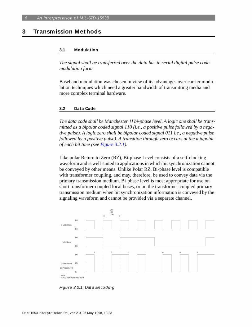
The data code shall be Manchester 1I bi-phase level. A logic one shall be trans-mitted as a bipolar coded signal 110 (i.e., a positive pulse followed by a nega-tive pulse). A logic zero shall be bipolar coded signal 011 i.e., a negative pulse followed by a positive pulse). A transition through zero occurs at the midpoint of each bit time (see Figure 3.2.1).
Like polar Return to Zero (RZ), Bi-phase Level consists of a self-clocking waveform and is well-suited to applications in which bit synchronization cannot be conveyed by other means. Unlike Polar RZ, Bi-phase level is compatible with transformer coupling, and may, therefore, be used to convey data via the primary transmission medium. Bi-phase level is most appropriate for use on short transformer-coupled local buses, or on the transformer-coupled primary transmission medium when bit synchronization information is conveyed by the signaling waveform and cannot be provided via a separate channel.
Figure 3.2.1: Data Encoding
OneBit
Time
(+) -
(0) -
(+) -
(0) -
(+) -
(0) -
(-) -
1 MHz Clock
*NRZ Data
Manchester II
Bi-Phase Level
Note*NRZ-Non return to zero
1 0 1 1 0 0 0
Doc: 1553 Interpretation.fm, ver 2.0, 26 May 1998, 13:23

Transmission Methods 7
With the Bi-phase Level data code, signal inversion can be caused by reversed connection of the data bus signal conductors.
3.3 Transmission Bit Rate
The transmission bit rate on the bus shall be 1.0 megabit per second with a com-bined accuracy and long-term stability of + 0.1%. The short-term stability (i.e., accuracy over 1.0 s interval) shall be at least 0.01%.
3.4 Word Size
The word size shall be 16 bits plus the synchronization signal (sync) and the parity bit for a total of 20 bit times as shown on Figure 3.5.1.
3.5 Word Formats
The word formats shall be as shown in Figure 3.5.1 for the command, data, and status words. A specification of each format is given in clauses 13-16.
The 20-bit word size represents the number of bit times for a word of 16 data bits, three bit time sync pattern and one bit time for a single parity bit. The three bit time sync pattern is described in clause 13.2.
Figure 3.5.1: Word Formats
PData Word
Count/Mode CodeSubaddress/
ModeRemote
Terminal AddressSync
1 2 3 4 5 6 7 8 9 10 11 12 13 14 15 16 17 18 19 20
5 1 5 5 1
T/R
PDataSync
16 1
RemoteTerminal Address
Sync
5 1 1 1 3 1 1 1 1 1 1
Reserved
Message E
rror
Instrumentation
Service R
equest
Dynam
ic Bus C
ontrol Acceptance
Terminal F
lag
Broadcast C
omm
and Received
Busy
Subsystem
Flag
P
NoteT/R - Transmit/ReceiveP - Parity
BitTimes
CommandWord
DataWord
StatusWord

8 An Interpretation of MIL-STD-1553B
4 Word Formats
4.1 Command Words
4.1.1 Content
A command word shall consist of a synchronization signal (sync), RT address, transmit/receive bit, subaddress/mode, data word count/mode code, and parity bit (see Figure 3.5.1).
4.1.2 Sync
The command sync waveform shall be an invalid Manchester waveform as shown on Figure 4.1.1. The width shall be three bit times, with the waveform be-ing positive for the first one and half bit times, and then negative for the follow-ing one and a half bit times. If the next bit following the sync is a logic zero, then the last half of the sync wave form will have an apparent width of two bit times due to the Manchester encoding.
Figure 4.1.1: Command and Status Sync Waveform
4.1.3 Remote Terminal (RT) Address
The next five bits following the sync shall be the RT address. Each RT shall be assigned to a unique address. Decimal address 31 (11111) shall not be assigned as a unique address. In addition to its unique address, a RT shall be assigned decimal address 31 (11111) as the common address, if the broadcast option is used.
Each remote terminal is assigned a unique address for which it is responsible to respond when that address is transmitted as part of a command word on the data bus by the active bus controller. It should be noted that decimal address 31 can-not be assigned as a unique address. This address has been assigned to all re-mote terminals as the common address for which they may receive broadcast data if the system uses the broadcast option (see clause 24).
AddressBit (1)
Word Sync
+ Volts
0
- Volts
Doc: 1553 Interpretation.fm, ver 2.0, 26 May 1998, 13:23

Word Formats 9
4.1.4 Transmit/Receive
The next bit following the address shall be the transmit/receive (TIR) bit, which shall indicate the action required of the RT. A logic zero shall indicate the RT is to receive, and logic one shall indicate the RT is to transmit.
4.1.5 Subaddress/Mode
The next five bits following the transmit/receive bit shall be used for either an RT subaddress or mode control, as is dictated by the individual terminal re-quirements. The subaddress/mode values of 00000 and 11111 are reserved for special purposes, as specified in clause 13.8, and shall not be used for any other functions.
This field has two mutually exclusive functions:
1. It identifies the subaddress of specific messages to a remote terminal.
2. It identifies that a mode command is being transmitted.
The use of either 00000 or 11111 in the subaddress/mode field is decoded to in-dicate that a mode code command is present in the next five bit field. In this case the subaddress range will be limited to 30 unique addresses. It is recommended that 11111 is used to invoke mode control in order to allow distinction to be made between command and status words as described in the explanation of clause 15.5. If the instrumentation bit in the status word is implemented, the su-baddress will be limited to 15 unique subaddresses. The requirements for use of the instrumentation bit are defined in clause 15.5.
The subaddress identification can serve to identify one of a number of sub-systems connected to a single RT, alternatively it may be used as pointer to spe-cific store locations in a single subsystem. It should be noted that by using the T/R bit, a maximum of 30 transmit and 30 receive subaddresses are available if the instrumentation bit is not used.
4.1.6 Data Word Count/Mode Code
The next five bits following the subaddress/mode control shall be the quantity of data words to be either sent out or received by the RT or the optional mode code as specified in clause 13.8. A maximum of 32 data words may be transmitted or received in any one message block. All 1's shall indicate a decimal count of 31, and all 0's shall indicate a decimal count of 32.
The dual function of this field provides for the identification of message lengths for data messages or mode codes for managing the information transfer system. The five bit field allows up to 32 data words to be transmitted in a message or 32 specified mode codes. As zero word count data cannot be sent, five bits can

10 An Interpretation of MIL-STD-1553B
specify up to 32 data words.
4.1.7 Parity
The last bit in the word shall be used for parity over the preceding sixteen bits. Odd parity shall be used.
The use of single parity bit per word is provided to identify any single or odd bit errors occurring during the transmission and detection of a word.
The total number of bits in any word, including the parity bit, should be odd. Only one parity bit is used as it is considered that this, together with the protec-tion provided by use of Manchester II encoding and the word synchronization field, gives adequate integrity. However, if a greater degree of integrity is re-quired, additional error checking capability may be incorporated in the data, such as Cyclic Redundancy Checks (CRC) or Checksums.
4.1.8 Optional Mode Control
For RT's exercising this option a subaddress/mode of 00000 or 11111 shall im-ply that the contents of the data word count/mode code field are to decoded as a five bit mode command. The mode codes shall only be used to communicate with the multiplex bus related hardware and to assist in the management of in-formation flow, and not to extract data from or feed data to a functional sub-system. Code 00000 to 01111 shall only be used for mode codes which do not require transfer of a data word. For these mode codes, the TIR bit shall be set to 1. Codes 10000 to 11111 shall only used for mode codes which require trans-fer of a single data word. For these mode codes, the TIR bit shall indicate the direction of data word flow as specified in clause 13.4. No multiple data word transfer shall be implemented with any mode code. The mode codes are reserved for the specific functions shown in Table 4.1.1 and shall not be used for any oth-er purpose. If the designer chooses to implement any of these functions, the spe-cific codes, TIR bit assignment, and the use of data word, shall be used as indicated. The use of the broadcast command option shall only be applied to particular mode codes as specified in Table 4.1.1.
Mode commands are used to manage the data bus system and are considered a necessary overhead to assist in the control of the data flow. The overheads com-prise command words and status words. Command and status words are associ-ated with both control messages and data messages. Message formats within this protocol can be transmitted to a single receiver or to multiple receivers based upon the command word address for the message.
Although the Standard states that the optional mode control function should not be used to extract data from or feed data to a functional subsystem, the extent of RT functions and hence those of subsystems can vary. There are also cases
Doc: 1553 Interpretation.fm, ver 2.0, 26 May 1998, 13:23

Word Formats 11
where mode commands may reflect back into the subsystem, for instance a broadcast sync command could be used to revert to a specific state or time (e.g., sync to weapon firing mode).
None of the mode codes are mandatory. Some RTs may not handle all mode codes. Use of those not implemented should provide an illegal command re-sponse (see clause 30.4).
Within the command word, the mode codes provide a data bus management ca-pability. The mode codes have been divided into two groups: mode codes with-out a data word (00000 - 01111) and mode codes with a data word (10000 - 11111). The use of bit 15 in the command word to identify the two groups was provided to aid in the decoding process. Also, the use of a single data word in-stead of multiple data words was adopted to simplify the mode circuitry within RT's. Generally, with these two groups of mode command, all management re-quirements of an information transfer system can be met.
Some mode codes in each of these two groups are reserved for future use (see clauses 13.8.10 and 13.8.17).
Table 4.1.1 provides a list of assigned mode codes indicating (in column d) whether or not a data word is associated with each mode code. In some cases e.g., transmit last command, the data word is associated with the response from the RT to a receive mode command rather than with the transmit mode com-mand. This is shown in the examples of all types of mode command transfer for-mats given in Figure 5.8.3.
Table 4.1.1: Assigned mode Codes
T/R Bit(a)
Mode Code
(b)Function (c)
Associated Data Words
(d)
Broadcast Command Allowed
(e)
1 00000 Dynamic Bus Control No No
1 00001 Synchronize No Yes
1 00010 Transmit Status No No
1 00011 Initiate Self Test No Yes
I 00100 Transmitter Shutdown No Yes
1 00101 Override Transmitter Shutdown No Yes
I 00110 Inhibit Terminal Flag Bit No Yes
1 00111 Override Inhibit Terminal Flag Bit No Yes
1 01000 Reset Remote Terminal No Yes
1 01001 Reserved No TBD*

12 An Interpretation of MIL-STD-1553B
4.1.8.1 Dynamic Bus Control
The controller shall issue a transmit command to an RT capable of performing the bus control function. This RT shall respond with a status word as specific in clause 15. Control of the data bus passes from the offering bus controller to the accepting RT upon transmission of the status word by the RT. If the RT rejects control of the data bus, the offering bus controller retains control of the data bus.
The dynamic bus control mode command (00000) is provided to allow the ac-tive bus controller a mechanism (using the information transfer system message formats) to offer a potential bus controller (operating as a remote terminal) con-trol of the data bus. The response to this offering of bus controller is provided by the receiving remote terminal setting the dynamic bus control acceptance bit in the status word (see clause 15.11). Rejection of this request by the remote ter-minal requires the presently active bus controller to continue offering control to other potential controllers or remain in control. When a remote terminal accepts control of the data bus system by setting the dynamic bus control acceptance bit in the status word, control is relinquished by the presently active bus controller handing over to the new bus controller.
Note: The sequence above requires software (or firmware) implementation in all bus controllers
101010
to01111
Reserved No TBD*
1 10000 Transmit Vector Word Yes No
0 10001 Synchronize Yes Yes
1 10010 Transmit Last Command Yes No
1 10011 Transmit Built In Test Word Yes No
0 10100 Selected Transmitter Shutdown Yes Yes
0 10101 Override Selected Transmitter Shut-down
Yes Yes
1 or 0 10110 Reserved Yes TBD*
1 or 010111
to11111
Reserved Yes TBD*
T/R Bit(a)
Mode Code
(b)Function (c)
Associated Data Words
(d)
Broadcast Command Allowed
(e)
Doc: 1553 Interpretation.fm, ver 2.0, 26 May 1998, 13:23

Word Formats 13
4.1.8.2 Synchronize (without data word)
This command shall cause the RT to synchronize (e.g., to reset the internal timer, to start a sequence, etc.). The RT shall transmit the status word as specified in clause 15.
See clause 13.8.12 for explanatory note.
4.1.8.3 Transmit Status Word
This command shall cause the RT to transmit the status word associated with the last valid command word. This mode command shall not alter the state of the status word.
This command would normally be used after a broadcast command or message transfer to determine whether an RT had correctly received the data. Normally status is reset on receipt of a valid command but this mode command enables the status word associated with the last valid command word to be obtained by the bus controller.
In some situations (for example, where the RT does something unexpected after receiving a command) the transmit last command can be used to determine what command the RT received (see clause 13.8.13). It is important to note that the transmit status word mode command will be stored in the RT's last command buffer, and thus the transmit last command mode command should be used first.
Terminal designers must ensure that in no circumstances must the content of the status word be changed from that which was associated with the previous valid command.
4.1.8.4 Initiate Self Test
This command shall be used to initiate self test within the RT. The RT shall transmit the status word as specific in clause 15.
The initiate self test mode command (00011) is provided to initiate Built In Test (BIT) circuitry within remote terminals. (Note: The abbreviation BIT is not to be confused with that for binary digit. The meaning of each is clear in the con-text in which they are used.) The mode code is usually followed, after sufficient time for test completion, by a transmit BIT word mode command yielding the results of the test. The message formats provided for this mode command allow for both individual requests and multiple requests via the Broadcast command. Notice that the initiate self test mode command is associated with the multiplex system terminal hardware only. The level of testing associated with this com-mand depends on the capability of the RT, and no specific requirements for BIT are specified within the Standard. It should also be noted that the status word

14 An Interpretation of MIL-STD-1553B
response required on receipt of the command does not indicate the result of the test, but only that the command has been received.
If a remote terminal cannot respond normally while carrying out a self test op-eration, the busy bit must be set in the status word. The RT must not go off-line during execution of a self test command.
4.1.8.5 Transmitter Shutdown
This command (to only be used with dual redundant bus systems) shall cause the RT to disable the transmitter associated with the redundant bus. The RT shall not comply with a command to shut down a transmitter on the bus from which this command is received. In all cases, the RT shall respond with a status word as specified in clause 15 after the command.
4.1.8.6 Override Transmitter Shutdown
This command (to only be used with dual redundant bus systems) shall cause the RT to enable a transmitter which was previously disabled. The RT shall not comply with a command to enable a transmitter on the bus from which this com-mand is received. In all cases, the RT shall respond with a status word as spec-ified in clause 15 after this command.
Four mode code commands (see clauses 13.8.5, 13.8.6, 13.8.15, and 13.8.16) are provided to control transmitters associated with terminals in a system. These commands can be sent to a single receiver or broadcast to multiple users. The above two commands are used in dual redundant systems to shutdown and re-start an RT transmitter. The transmitter shut down command would normally be used to disable a "jabbering" transmitter. (see clause 28.3 for details of the ter-minal fail-safe mechanism which should also operate in these circumstances). Note that the bus controller must issue this command on the standby bus.
4.1.8.7 Inhibit Terminal Flag (T/F) Bit
This command shall cause the RT to set the T/F bit in the status word specified in clause 15 to logic zero until otherwise commanded. The RT shall transmit the status word as specified in clause 15.
The inhibit terminal flag mode code (00110) is used to set the terminal flag bit in the status word to an unfailed condition regardless of the actual sate of the terminal flag being addressed. This mode code is primarily used to prevent con-tinued interrupts to the error handling and recovering system when the failure has been noted and the system reconfigured as required. Commanding this mode code prevents future failures from being reported which would normally be reported using the terminal flag in each subsequent status word response. The message format associated with this mode code allows for both single receivers and broadcast receivers to respond. No data word is required with this mode
Doc: 1553 Interpretation.fm, ver 2.0, 26 May 1998, 13:23

Word Formats 15
code. Depending on the implementation, this command may be registered in the returned status word, but it should not be registered until the next status word. Therefore, to be positive, it is advisable to interrogate the status word with a sep-arate command.
Note: The terminal flag, which is used to indicate an RT fault condition, is implicitly limited to terminal faults.
4.1.8.8 Override Inhibit (T/F Bit)
This command shall cause the RT to override the inhibit T/F bit specified in clause 13.8.7. The RT shall transmit the status word as specified in clause 15.
The override inhibit T/F bit mode command (00111) negates the inhibit func-tion, thus allowing the T/F bit in the status response to report the present condi-tion of the terminal. Note: It is advisable to interrogate the status word with a separate command in this case. This mode code can be transmitted by the bus controller to both single and broadcast receivers. There is no data word associ-ated with this mode code.
4.1.8.9 Reset Remote Terminal
This command shall be used to reset the RT to a power up initialized state. The RT shall first transmit its status word, and then reset.
If a remote terminal cannot respond normally while undergoing reset, the busy bit must be set in the status word. The RT must be capable of receiving the next valid command.
4.1.8.10 Reserved Mode Codes (01001 to 01111)
These mode codes are reserved for future use and shall not be used.
4.1.8.11 Transmit Vector Word
This command shall cause the RT to transmit a status word as specified in clause 15 and a data word containing service request information.
The transmit vector word mode code (10000) is associated with the service re-quest bit in the status word and is used to determine specific service being re-quired by the terminal. The service request bit and the transmit vector word are the only means available for the terminal to request the scheduling of an a peri-odic message. The message format for this single receiver operation contains a data word associated with the terminal's response. Figure 4.3.1 illustrates the use of this mode command in association with the service request bit.

16 An Interpretation of MIL-STD-1553B
4.1.8.12 Synchronize (with data word)
The RT shall receive a command word followed by a data word as specified in clause 14. The data word shall contain synchronization information for the RT. After receiving the command and data word, the RT shall transmit the status word as specified in clause 15.
Synchronize mode commands (see also clause 13.8.2) inform the terminal(s) of an event time to allow coordination between the active bus controller and receiv-ing terminals. Synchronization information may be implicit in the command word (mode code 00001), or a data word (mode code 10001) may be used to fol-low the command word to provide the synchronization information. If a data word is used, the definition of the bit meanings is the responsibility of the sys-tem designer. These may not necessarily be only associated with the manage-ment of data flow, they may also be used as system control functions.
4.1.8.13 Transmit Last Command Word
This command shall cause the RT to transmit its status word as specified in clause 15 followed by a single data word which contains bits 4-19 of the last command word, excluding a transmit last command word mode code received by the RT. This mode command shall not alter the state of the RT's status word.
The transmit last command mode code (10010) is used in the error handling and recovery process to determine the last valid command received by the terminal, prior to this mode code. Note that this mode code will not change the contents of the last command or the status word. A remote terminal receiving this mode command will transmit the previous status word followed by a data word which contains the previous 16-bits of the last valid command word received. Notice that this mode command will not alter the state of the receiving terminal's status word, thus allowing this mode command to be used in error handling and recov-ery operation without affecting the status word which can have added error data.
4.1.8.14 Transmit Built-In-Test (BIT) Word
This command shall cause the RT to transmit its status word as specified in clause 15 followed by a single data word containing the RT built-in-test (BIT) data. This function is intended to supplement the available bits in the status word when the RT hardware is sufficiently complex to warrant its use. The data, containing the RT BIT data, shall not be altered by the reception of a transmit last command or a transmit status word mode code. This function shall not be used to convey BIT data from the associated subsystem(s).
The transmit BIT word mode code (10011) provides the bus controller with the BIT results available from a terminal, as well as the status word. Obviously the bus controller must not issue this as a broadcast command. The contents of the BIT data word are provided to supplement the appropriate bits already available
Doc: 1553 Interpretation.fm, ver 2.0, 26 May 1998, 13:23

Word Formats 17
via the status word for complex terminals, and designers are free to use these as required. Notice that the contents of the BIT word within the remote terminal "...shall not be altered by the reception of a transmit last command or a transmit status word mode code". This allows error handling and recovery procedures to be used without changing the error data recorded in this word. However, the RT will only save the last command, and the status code field (of the status word) will not be changed if transmit last command or transmit status word mode com-mands are transmitted. If, however, any other transmissions are made to the RT, the status code field may change, for example, if a message error occurred dur-ing the transmission. See clause 13.8.3 and clause 13.8.13.
Another point worth noting is that the function of transmitting RT BIT data "shall not be used to convey BIT data from the associated subsystem(s)." Sub-system fault investigation, when indicated by the subsystem flag, is not specified or otherwise restricted by MIL-STD-1553. System designers must, therefore, make the necessary provisions.
4.1.8.15 Selected Transmitter Shutdown
This command shall cause the RT to disable the transmitter associated with a specified redundant data bus. The command is designed for use with systems employing more than two redundant buses. The transmitter that is to be disabled shall be identified in the data word following the command word in the format as specified in clause 14. The RT shall not comply with a command to shut down a transmitter on the bus from which this command is received. In all causes the RT shall respond with a status word as specified in clause 15.
4.1.8.16 Override Selected Transmitter Shutdown
This command shall cause the RT to enable a transmitter which was previously disabled. The command is designed for use with systems employing more than two redundant buses. The transmitter that is to be enabled shall be identified in the data word following the command word in the format as specified in clause 14. The RT shall not comply with a command to enable a transmitter on the bus from which this command is received. In all cases, the RT shall respond with a status word as specified in clause 15.
Four mode code commands (see clauses 13.8.5, 13.8.6, 13.8.15, and 13.8.16) are provided to control transmitters associated with terminals in a system. These commands can be sent to a single receiver or broadcast to multiple users. Care should be taken to ensure that all RT's are aware of the bus numbering conven-tion.

18 An Interpretation of MIL-STD-1553B
4.1.8.17 Reserved Mode Codes (10110 to 1111)
These mode codes are reserved for future use and shall not be used.
Any future use of reserved mode codes will be notified in updated issues of the Standard.
4.2 Data Word
4.2.1 Content
The data word shall consist of a sync waveform, data bits and parity bit (see Figure 3.5.1).
4.2.2 Sync
The data sync waveform shall be an invalid Manchester waveform as shown on Figure 4.2.1. The width shall be three bit times, with the waveform being nega-tive for the first one and on-half bit times, and then positive for the following one and one-half bit times. Note that if the bits proceeding and following the sync are logic ones, then the apparent width of the sync waveform will be increased to four bit times.
Figure 4.2.1: Data Sync Waveform
Note that the term invalid Manchester waveform refers to the description of the waveform in terms of the Manchester bi-phase encoding. Being a defined part of the message, it is actually valid for detection purposes.
4.2.3 Data
The 16 bits following the sync shall be used for data transmission as specified in clause 7.
DataBit (0)
+ Volts
0
- Volts
Word SyncParityBit (0)
Doc: 1553 Interpretation.fm, ver 2.0, 26 May 1998, 13:23

Word Formats 19
4.2.4 Parity
The last bit shall be used for parity as specified in clause 13.7.
Data words are distinguished from command and status words by the inverted 3-bit sync pattern. Both packed and unpacked data may be transmitted in the 16-bit data field. Odd parity on the data field provides a data integrity check iden-tical to the command and status word formats.
4.3 Status Word
4.3.1 Content
A status word shall consist of a sync waveform, RT address, message error bit, instrumentation bit, service request bit, three reserved bits, broadcast command received bit, busy bit, subsystem flag bit, dynamic bus control acceptance bit, terminal flag bit, and a parity bit. For optional broadcast operation, transmis-sion of the status word shall be suppressed as specified in clause 24.
4.3.2 Sync
The sync waveform shall be as specified in clause 13.2.
4.3.3 RT Address
The next five bits following the sync shall contain the address of the terminal which is transmitting the status word as defined in clause 13.3.
4.3.4 Message Error Bit
The status word bit at bit time nine (see Figure 3.5.1) shall be used to indicate that one or more of the data words associated with the preceding receive com-mand from the bus controller has failed to pass the RT's validity test as specified in clause 28.1. This bit shall also be set under the conditions specified in clauses 28.2, 30.4, and 30.6. A logic one shall indicate the presence of a message error, and logic zero shall show its absence. All RT's shall implement the message er-ror bit.
The message error bit is set to logic one to indicate one or more of the data words associated with the preceding received message has failed to pass the message validity test. The message validity requirements are:
➢ Word Validation: Word begins with valid sync, Manchester II code correctly transmitted, 16 data bits plus parity, and word parity odd. Invalid commands should not set the message error bit.
➢ Continuous words within a message.

20 An Interpretation of MIL-STD-1553B
➢ Address Validation: Matches address to unique terminal or broadcast address. Messages with incorrect addresses should be treated as being invalid.
Terminals that do detect illegal commands set the message error bit and transmit the status word (see clause 30.4). Illegal commands should not be confused with invalid command (see clause 30.3).
The status word will be transmitted as shown in the data and mode code mes-sage formats (see Figure 4.3.1 and Figure 4.3.2) if the message validity require-ments are met. When a message error occurs in a broadcast message format, the message error bit will be set in the status word and the status response withheld as required by broadcast message format. It should be noted that any error con-dition renders the entire message invalid.
4.3.5 Instrumentation Bit
The status word bit at bit time ten (see Figure 3.5.1) shall be reserved for the instrumentation bit and shall always be a logic zero. This bit is intended to be used in conjunction with a logic one in bit time ten of the command word to dis-tinguish between a command word and a status word. The use of the instrumen-tation bit is optional.
Since the sync field (3 bits) is used to distinguish command/status words from data words on the bus, a mechanism is also required to enable passive monitor-ing equipment to distinguish between command and status words so as to inter-pret the bus traffic correctly. If this bit is used the Standard specifies setting bit 10 in the command word to a logic one which can then be distinguished from the corresponding bit 10 in the status word (instrumentation bit) which is always set to logic zero. The use of the instrumentation bit, however, results in the loss of fifteen usable subaddresses, 00001 to 01111, and 00000 for mode command identification.
An alternative method can be defined which only involves the loss of one usable subaddress. For this method the system designer must prohibit the use of sub-address codes 01000 and 00000 in the command word. As a result, examination of bits 10, 12, 13, and 14 would only reveal all logic zeros if the word in question was a status word. This is true because this combination of zero bits can no long-er occur in any command word thus providing immediate and correct separation of command and status words. Either one or other of the above two methods of distinguishing between command and status words could be used.
4.3.6 Service Request Bit
The status word bit at bit time eleven (see Figure 3.5.1) shall be reserved for the service request bit. The use of this bit is optional. This bit, when used, shall in-
Doc: 1553 Interpretation.fm, ver 2.0, 26 May 1998, 13:23
Word Formats 21
dicate the need for the bus controller to take specific predefined actions relative to the RT or associated subsystem. Multiple subsystems, interfaced to a single RT, which individually require a service request signal shall logically "OR" their individual signals into the single status word bit. In the event this logical "OR" is performed, then the designer must make provisions in a separate data word to identify the specific requesting subsystem. The service request bit is in-tended to be used only to trigger data transfer operations which take place on an exception rather than periodic basis. A logic one shall indicate the presence of a service request, and a logic zero its absence. If this function is not imple-mented, the bit shall be set to zero.
The service request bit is provided to indicate to the active bus controller that a remote terminal requests service. When this bit in the status word is set to logic one, the active bus controller uses a mode command (transmit vector word) to identify the specific request (Figure 4.3.1). The message format for acquiring this is discussed under transmit vector word mode command (see clause 13.8.11).
4.3.7 Reserved Status Bits
The status word at bit times 12 to 14 are reserved for future use and shall not be used. These bits shall be set to a logic zero.
4.3.8 Broadcast Command Received Bit
The status word bit at bit time 15 shall be set to a logic one to indicate that the preceding valid command word was a broadcast command and a logic zero shall show it was not a broadcast command. If the broadcast command option is not used, this bit shall be set to logic zero.
The broadcast command received bit is set to logic one when the preceding valid command word was a broadcast command (address 31). Since the broadcast message format requires the receiving remote terminals to suppress their status words, the broadcast command received bit is set to identify that the command was received properly.
If the broadcast message validity is required by the bus controller, the message format illustrated on Figure 4.3.2 is used to determine this information. The broadcast command received bit will be reset when the next valid (non-broad-cast) command is received by the remote terminal, unless the next valid com-mand is a transmit status word or a transmit last command mode command.

22 An Interpretation of MIL-STD-1553B
Figure 4.3.1: Transmit Vector Word Transfer Format
Figure 4.3.2: Broadcast Command Received Bit
Bus ControllerReturns to
# Synchronous BusListSource: Single Receiver A periodic Information
Service VectorInformation
# Continuedbelow
Source: Single Receiver
**
RemoteTerminal Address
Sync
5 1 1 1 3 1 1 1 1 1 1
Reserved
Message E
rror
Instrumentation
Service R
equest
Dynam
ic Bus C
ontrol Acceptance
Terminal Flag
Broadcast C
omm
and Received
Busy
Subsystem
Flag
Source: Bus ControllerAddress: Unique-31Subaddress: Unique - 00000 or 11111Data Word Count: 1-32T/R: Receive
StatusWord
CommandWord
DataWord
DataWord
StatusResponse
Single Receiver Only - Bus Controller to Remote Terminal
# Continuedbelow
3 8 11 14 20
**
RemoteTerminal Address
Sync
5 1 1 1 3 1 1 1 1 1 1
Reserved
Message E
rror
Instrumentation
Service R
equest
Dynam
ic Bus C
ontrol Acceptance
Terminal Flag
Broadcast C
omm
and Received
Busy
Subsystem
Flag
Source: Bus ControllerAddress: Unique Address of S/RStatus ResponseSubaddress: 00000 or 11111Mode Code: 10000
StatusWord
Mode CodeCommand
DataWord
StatusResponse
3 8 11 14 20
**Source: Bus ControllerAddress: Unique Address of S/RSubaddress: Unique Address ofService Vector InformationT/R: Transmit
CommandWord
DataWord
DataWord
StatusResponse
Notes** Response Time# Intermessage Gap
Parity
Parity
Parity
Source: SingleReceiver
Service Request Bit Set to "U" (if no new service requests are present)
Service Request Bit Set to "1"
Source: Bus ControllerAddress: Unique - 31 (11111)Subaddress: 00000 or 11111Mode Code: 00010
Multiple Receivers
Active Bus Controller to Remote Terminals
**#
Source: Single Receiver
RemoteTerminal Address
Sync
5 1 1 1 3 1 1 1 1 1 1
Reserved
Message Error
Instrumentation
Service Request
Dynamic Bus Control Acceptance
Terminal Flag
Broadcast Command Received
Busy
Subsystem Flag
Source: Bus ControllerAddress: 31 (11111)Subaddress: Unique - 00000 or 11111Data Word Count: 1-32T/R: Receive
StatusWord
CommandWord
DataWord
DataWord
Mode CodeCommand
3 8 11 14 20
StatusResponse
Notes** Response Time# Intermessage Gap
Parity
Status Word Transmitted With Broadcast
Command Received Bit Set
Doc: 1553 Interpretation.fm, ver 2.0, 26 May 1998, 13:23

Word Formats 23
4.3.9 Busy Bit
The status word bit at bit time 16 (see Figure 3.5.1) shall be reserved for the busy bit. The use of this bit is optional. This bit, when used, shall indicate that the RT or subsystem is unable to move data to or from the subsystem in compli-ance with the bus controller's command. A logic one shall indicate the presence of a busy condition, and logic zero its absence. In the event the busy bit is set in response to a transmit command, then the RT shall transmit its status word only. If this function is not implemented, the bit shall be set to logic zero.
The busy bit in the status word (see Figure 4.3.1) is set to logic one to indicate to the active bus controller that the remote terminal is unable to move data to or from the subsystem in compliance with the bus controller's command. It should be noted that allowing the system to become "busy" and thereby setting the busy bit should be restricted to that of an exception basis e.g. periods of high loads in subsystems. Setting the busy bit is not to be used as means of overcoming prob-lems associated with slow acting remote terminals.
The message format associated with a busy condition is shown in Figure 4.3.1. A busy condition can exist within a remote terminal at any time causing it to be non-responsive to a command to send data or to be unable to receive data. This condition can exist for all message formats. In each case, except for broadcast message formats, the active bus controller will be informed within the status re-sponse of the busy condition. In the case of broadcast message formats, this in-formation will not be made known unless the receiving terminals are polled, after the broadcast message, requesting their status. If the status word has the broadcast received bit set, the message was received and the terminal was not busy.
4.3.10 Subsystem Flag Bit
The status word bit at bit time 17 (see Figure 3.5.1) shall be reserved for the sub-system flag bit. The use of this bit is optional. This bit, when used, shall flag a subsystem fault condition and alert the bus controller to potentially invalid data. Multiple subsystems, interfaced to a single RT, which individually require a sub-system flag bit signal shall logically "OR" their individual signals into a single status word bit. In the event that this logical "OR" is performed, the designer must make provisions in a separate data word to identify the specific reporting subsystem. A logic one shall indicate the presence of the flag, and logic zero its absence. If not used, this bit shall be set to logic zero.

24 An Interpretation of MIL-STD-1553B
Figure 4.3.3: Busy Bit
4.3.11 Dynamic Bus Control Acceptance Bit
The status word bit at bit time 18 (see Figure 3.5.1) shall be reserved for the ac-ceptance of dynamic bus control. This bit shall be used if the RT implements the optional dynamic bus control function. This bit, when used, shall indicate ac-ceptance or rejection of a dynamic bus control offer as specified in clause 13.8.1. A logic one shall indicate acceptance of control, and a logic zero shall indicate rejection of control. If this function is not used, this bit shall be set to logic zero.
Discussion of the use of dynamic bus control is given in clause 13.8.1.
4.3.12 Terminal Flag Bit
The status word bit at bit time 19 (see Figure 3.5.1) shall be reserved for the ter-minal flag function. The use of this bit is optional. This bit, when used shall flag an RT fault condition. A logic one shall indicate the presence of the flag, and logic zero its absence. If not used, this bit shall be set to logic zero.
4.3.13 Parity Bit
The least significant bit in the status word shall too be used for parity as speci-fied in clause 13.7.
Single Receiver Active Bus Controller to Remote Terminal
** #
RemoteTerminal Address
Sync
5 1 1 1 3 1 1 1 1 1 1
Reserved
Message E
rror
Instrumentation
Service R
equest
Dynam
ic Bus C
ontrol Acceptance
Terminal F
lag
Broadcast C
omm
and Received
Busy
Subsystem
Flag
Source: Bus ControllerAddress: - 31 (11111)Subaddress: Unique - 00000 or 11111Data Word Count: 1-32T/R: Transmit
StatusWord
CommandWord
StatusResponse
3 8 11 14 20
Notes** Response Time# Intermessage Gap
Parity
Source: Single Receiver
Doc: 1553 Interpretation.fm, ver 2.0, 26 May 1998, 13:23

Word Formats 25
4.4 Status Word Reset
The status word bits, with the exception of the address, shall be set to logic zero after a valid command word is received by the RT with the exceptions as speci-fied in clause 13.8. If the conditions which caused bits in the status word to set (e.g. terminal flag) continue after the bits are reset to logic zero, then the affect-ed status word bits shall be again set, and then transmitted on the bus as re-quired.
It is to be noted that:
1. Status is constructed on a message by message basis on receipt of each valid command word. Remote terminals are required to store the status word between valid command words so that it is available for interrogation using the transmit status word mode code.
2. It is recommended that the terminal flag bit and subsystem flag bit, having once been set, should remain set until a reset remote terminal mode command is received or a power-up initialization occurs.
3. The inhibit terminal flag mode code locally suppresses the terminal flag bit in the status word so preventing failures of the RT from being reported in that way.
The above three facilities allow an orderly error handling and recovery approach to be accomplished by the bus controller using the information associated with error analysis data contained within the status word or other data associated with the RT (e.g. last command word and BIT word).

26 An Interpretation of MIL-STD-1553B
5 Message Formats
5.1 Message Formats
The messages transmitted on the data bus shall be in accordance with the for-mats in Figure 5.1.1 and Figure 5.1.2. The maximum and minimum response times shall be as stated in clauses 25 and 26. No message formats, other than those defined below, shall be used on the bus.
Figure 5.1.1: Information Transfer Formats
Figure 5.1.2: Broadcast Information Transfer Formats
The command/response protocol provides two types of message formats, i.e., control messages and data messages. Control messages are identified by the su-
Mode Commandwithout Data Word
Mode Command withData Word (Receive)
Notes
** response time
# intermessage gap
Mode Command withData Word (Transmit)
RT to RTTransfer
RT to BCTransfer
BC to RTTransfer #**...Receive
CommandData Word Data Word Data Word
StatusWord
NextCommand
Word
** #TransmitCommand
NextCommand
Word
StatusWord
...Data Word Data Word Data Word
**** #ReceiveCommand
NextCommand
Word
StatusWord
...Data Word Data Word Data WordTransmitCommand
StatusWord
#**Mode
CommandStatusWord
NextCommand
Word
#**Mode
CommandStatusWord
NextCommand
WordData Word
#**Mode
CommandStatusWord
NextCommand
WordData Word
#
#...ReceiveCommand
Data Word Data Word Data WordNext
CommandWord
BC to RT(s)Transfer
**Receive
Command
NextCommand
Word
RT to RT(s)Transfer
StatusWord
...Data Word Data Word Data WordTransmitCommand
#ModeCommand
NextCommand
Word
Mode Commandwithout Data Word
#Mode
Command
NextCommand
Word
Mode Command withData Word (Receive)
** response time
# intermessage gap
Data Word
Doc: 1553 Interpretation.fm, ver 2.0, 26 May 1998, 13:23

Message Formats 27
baddress/mode field in the command word being set to 31 (11111) or 32 (00000). (In this case, the Standard defines decimal subaddress 32 to be equal to binary 00000 so that decimal 1 to 31 correspond to binary 00001 to 11111). All control messages originate with the active bus controller and are received by a single receiver or by multiple receivers (broadcast). A terminal address value of 31 (11111) in the command word indicates a broadcast message, while any other terminal addresses are to identify unique messages to a terminal on the bus. The mode command information is contained completely in the mode code/word count field of the command word. More general discussion of the use of mode commands is contained in clause 13.8.
The various legal mode commands with and without data word are illustrated in Figure 5.8.3.
5.2 Bus Controller to Remote Terminal Transfers
The bus controller shall issue a receive command followed by the specific num-ber of data words. The RT shall, after message validation, transmit a status word back to the bus controller. The command and data words shall be trans-mitted in a contiguous fashion with no interword gaps.
5.3 Remote Terminal to Bus Controller Transfers
The bus controller shall issue a transmit command to the RT. The RT shall, after command verification, transmit a status word back to the bus controller, fol-lowed by the specified number of data words. The status and data words shall be transmitted in a contiguous fashion with no interword gaps.
5.4 Remote Terminal to Remote Terminal Transfers
The bus controller shall issue a receive command to RT A followed contiguously by a transmit command to RT B. RT B shall, after command verification, trans-mit a status word followed by the specified number of data words. The status and data words shall be transmitted in a contiguous fashion with no interword gaps. At the conclusion of the data transmission by RT B, RT A shall transmit a status word within the specified time period (see clause 26).
For the above three types of message transfers, it should be noted that successive message transfers to or from the same RT causes a high throughput. It is pre-ferred that if the subsystem is unable to handle the required message rate, the busy bit should be set as necessary to ensure data is not lost.

28 An Interpretation of MIL-STD-1553B
5.5 Mode Command without Data Word
The bus controller shall issue a transmit command to the RT using a mode code specified in Table 4.1.1. The RT shall, after command validation, transmit a sta-tus word.
5.6 Mode Command with Data Word (Transmit)
The bus controller shall issue a transmit command to the RT using the mode code specified in Table 4.1.1. The RT shall, after command word verification, transmit a status word followed by one data word. The status word and data word shall be transmitted in a contiguous fashion with no gap.
5.7 Mode Command with Data Word (Receive)
The bus controller shall issue a receive command to the RT using a mode code specified in Table 4.1.1, followed by one data word. The command word and data word shall be transmitted in a contiguous fashion with no gap. The RT shall, after command and data word validation, transmit a status word back to the controller.
5.8 Optional Broadcast Command
This mode allows one transmission to be simultaneously received by more than one RT but no status word reply will be made by any RT.
The broadcast mode provides a mechanism for transmitting information to mul-tiple users with a single message. The mechanism for accomplishing this is to reserve address 31 (11111) for broadcast messages. When a broadcast message is transmitted, the transmitting terminal uses address 31 rather than a unique ter-minal address. All addresses other than 31 can be assigned to remote terminals. Since multiple users receive a broadcast message, the responding status word must be suppressed. By choosing the address method to accomplish the broad-cast mode, all the other formats of the command word are available for use. Broadcast messages can be used with subaddresses and mode codes. The sub-address in a broadcast message can allow multiple users with the broadcast re-ception capability to sort out specific broadcast messages transmitted, if given this capability in hardware or software. Therefore, multiple sets of broadcast messages can be defined. In addition, the broadcast format can be used with some mode codes. This allows simultaneous reception of these mode com-mands by terminals.
Designers must consider carefully discarding the command-response format, in which all message completion failures are known to the bus controller, for the
Doc: 1553 Interpretation.fm, ver 2.0, 26 May 1998, 13:23

Message Formats 29
benefits of using broadcast message transfers. Broadcast use may increase sys-tem operation complexity since subaddresses of broadcast address and ad-dressed terminal are not likely to be the same. This requires additional sub addresses .
Proper use of the broadcast mode may yield benefits by allowing simultaneous communication with remote terminals and may also reduce bus traffic.
5.8.1 Bus Controller to Remote Terminal(s) Transfer (Broadcast)
The bus controller shall issue a receive command word with 11111 in the RT ad-dress field followed by the specified number of data words. The command words and data words shall be transmitted in a contiguous fashion with no gap. The RT(s) with the broadcast options shall, after necessary validation, set the broad-cast command received bit in the status word as specified in clause 15.8 and shall not transmit the status word.
5.8.2 Remote Terminal to Remote Terminal(s) Transfer (Broadcast)
The bus controller shall issue a receive command word with 11111 in the RT ad-dress field followed by a transmit command to RTA using that RT's address. RTA shall, after command verification, transmit a status word followed by the spec-ified number of data words. The status and data words shall be transmitted in a contiguous fashion with no gap. The RT(s) with the broadcast option, excluding RT A, shall after message validation set the broadcast received bit in the status word as specified in clause 15.8 and shall not transmit the status word.
The single and broadcast receiver data message formats are shown on Figure 5.8.1 and Figure 5.8.2.

30 An Interpretation of MIL-STD-1553B
Figure 5.8.1: Single Receiver Data Message Formats
Source: Single Receiver
#**
Remote Terminal to Remote Terminal
#
**Command
WordDataWord
DataWord
StatusResponse
Bus Controller to Remote Terminal
#
Source: Bus ControllerAddress: Unique - 31Subaddress: Unique - 31 and 32Word Count: 1-32T/R: Receive
Source: Single Receiver Number of Data Words Required
**Source: Bus ControllerAddress: Unique - 31Subaddress: Unique - 31 and 32Word Count: 1-32T/R: Transmit
CommandWord
DataWord
DataWord
StatusResponse
Remote Terminal to Bus Controller
DataWord
Source: Receiver (B)
**Source: Bus ControllerAddress: Unique (A) - 31Subaddress: Unique - 31and 32Word Count: 1-32T/R: Receive
CommandWord
DataWord
DataWord
StatusResponse
CommandWord
Source: Bus ControllerAddress: Unique (B) - 31Subaddress: Unique - 31and 32Word Count: 1-32T/R: Transmit
Source: Receiver (A)
StatusResponse
Notes** Response Time# Intermessage Gap
Doc: 1553 Interpretation.fm, ver 2.0, 26 May 1998, 13:23

Message Formats 31
Figure 5.8.2: Multiple Receiver Data Message Formats
5.8.3 Mode Command Without Data Word (Broadcast)
The bus controller shall issue a transmit command word with 11111 in the RT address field and a mode code specified in Table 4.1.1. The RT(s) with the broadcast option shall, after message validation, set the broadcast received bit in the status word as specified in clause 15.8 and shall not transmit the status word.
5.8.4 Mode Command with Data Word (Broadcast)
The bus controller shall issue a receive command word with 11111 in the RT ad-dress field and a mode code specified in Table 4.1.1, followed by one data word. The command word and data word shall be transmitted in a contiguous fashion with no gap. The RT(s) with the broadcast option shall, after message valida-
Remote Terminal to Remote Terminals
Bus Controller to Remote Terminals
CommandWord
DataWord
DataWord
DataWord
#
Source: Bus ControllerAddress: 31 (11111)Subaddress: Unique - 31 and 32Word Count: 1-32T/R: Receive
CommandWord
CommandWord
StatusResponse
#
Source: Receiver (A)
**
DataWord
DataWord
DataWord
Source: Bus ControllerAddress:31 (11111)Subaddress: Unique - 31and 32Word Count: 1-32T/R: Receive
Source: Bus ControllerAddress: Unique (A) - 31Subaddress: Unique - 31and 32Word Count: 1-32T/R: Transmit
Notes** Response Time# Intermessage Gap

32 An Interpretation of MIL-STD-1553B
tion, set the broadcast received bit in the status word as specified in clause 15.8 and shall not transmit the status word.
Mode command transfer formats are shown in Figure 5.8.3.
Figure 5.8.3: Mode Command Transfer Formats
5.9 Intermessage Gap
The bus controller shall provide a minimum gap time of 4.0 µs between messag-es as shown in Figure 5.1.1 and Figure 5.1.2. This time period, shown as T in Figure 5.10.1, is measured at point A of the bus controller as shown in Figure 5.11.1 or Figure 7.2.1. The time is measured from the mid-bit zero crossing of the last bit of the preceding message to the mid-zero crossing of the next com-mand word sync.
The purpose of this clause is to clearly identify that the bus controller shall not
#
#
#**
#
Mode Command without Data Word to a Single Receiver
**Mode CodeCommand
StatusResponse
Source: Single ReceiverSource: Bus Controller
#
Transmit Mode Command with Data Word to a Single Receiver
**Mode CodeCommand
StatusResponse
Source: Single ReceiverSource: Bus Controller Mode Data Response
DataWord
Receive Mode Command with Data Word to a Single Receiver
Mode CodeCommand
Source: Bus Controller Mode Data Word
DataWord
StatusResponse
Source: Single Receiver
Transmit Mode Command without Data Word to Multiple Receivers
Mode CodeCommand
Source: Bus Controller
Transmit Mode Command with Data Word to a Multiple Receivers
Mode CodeCommand
Source: Bus Controller Mode Data Word
DataWord
Notes** Response Time# Intermessage Gap
Doc: 1553 Interpretation.fm, ver 2.0, 26 May 1998, 13:23

Message Formats 33
transmit contiguous messages. There must be an intermessage gap so that any voltage build-up can dissipate (see explanatory note for clause 36.1.4). There is not maximum gap time specified. The bus controller may issue messages with gap time greater than or equal to 4 µs.
5.10 Response Time
The RT shall respond, in accordance with clause 17 to a -valid command word within the time period of 4.0 to 12.0 µs. This time period, shown at T in Figure 5.10.1, is measured at point A of the RT as shown in Figure 5.11.1 or Figure 7.2.1. The time is measured from the mid-bit zero crossing of the last bit of the last word as specified in clause 17 and as shown in Figure 5.1.1 and Figure 5.1.2 to the mid-zero crossing of the status word sync.
Figure 5.10.1: Intermessage Gap and Response Time
The point of measurement of response time is identified on Figure 5.10.1 using the previous mid-bit zero crossing and the next mid-bit crossing. Values of 4 and 12 µs would equate to 2 and 10 µs, respectively of bus quiet time.
Parity Bit
20
Bit Time
Command/Status/Sync
1 2
Bit Time
T
+ Volts
0 Volts
- Volts
Note: T is the repsonse time of an RT (see clauses 26 and 27)
19 3

34 An Interpretation of MIL-STD-1553B
5.11 Minimum No-Response Timeout
The minimum time that a terminal shall wait before considering that a response as specified in clause 26 has not occurred shall be 14.0 µs. The time is measured from the mid-bit zero crossing of the last bit of the last word to the mid-zero crossing of the expected status word sync at point A of the terminal as shown on Figure 5.11.1 or Figure 7.2.1.
Figure 5.11.1: Data Bus Interface using Transformer Coupling
Bus CableScreen
Data BusWire Pair
Screening
R R
Transmitter/Receiver
Terminal
IsolationTransformer
A
Stub ofSpecifiedLength
Doc: 1553 Interpretation.fm, ver 2.0, 26 May 1998, 13:23

Message Formats 35
The main intention of this clause is to specify the minimum time that a bus con-troller shall wait after sending a command before concluding that the addressed remote terminal (RT) is not going to respond before sending a subsequent com-mand.
This clause can also be interpreted to apply to the receiving RT in a RT to RT transfer to check for the correct response from the transmitting RT. This condi-tion should, if detected, prevent the receiving RT from remaining "open" to data from another source if the transmitting RT does not respond to its command in time, and should cause the RT to abort any operations associated with the first receive command.

36 An Interpretation of MIL-STD-1553B
6 Terminal Operation
6.1 Common Operation
Terminals shall have common operating capabilities as specified in the follow-ing clauses.
6.1.1 Word Validation
The terminal shall ensure that each word conforms to the following minimum criteria:
(a) The word begins with a valid sync field
(b) The bits are in a valid Manchester II code
(c) The information field has 16 bits plus parity
(d) The word parity is odd
When a word fails to conform to the preceding criteria, the word shall be con-sidered invalid.
6.1.2 Transmission Continuity
The terminal shall verify that the message is contiguous as defined in Section E. Improperly timed data syncs shall be considered a message error.
In this context, improperly timed data syncs relate to clauses 36.1.2 and 37.1.2 in respect to the zero crossing accuracy expected for a transmitter.
For contiguous words, it is required that the time interval from the last zero crossing of one word to the first zero crossing of the next word, measured at the transmitter into a test load is 2 µs + 25 ns. Given normal transmission charac-teristics, this will result in a corresponding time interval at the receiver within 2 µs + 150 ns. This interpretation is based on the timing detail given in clauses 36.1.2 and 37.1.2.
6.1.3 Terminal Fail-Safe
The terminal shall contain a hardware implemented time-out to preclude a sig-nal transmission of greater than 800.0 µs. This hardware shall not preclude a correct transmission in response to a command. Reset of this time-out function shall be performed by the reception of a valid command on the bus on which the time-out has occurred.
Doc: 1553 Interpretation.fm, ver 2.0, 26 May 1998, 13:23

Terminal Operation 37
The above clauses describe the common operating capabilities that all terminals must have whether operating as a bus monitor, remote terminal or bus controller. A time-out function should be associated with each individual transmitter.
The purpose of the fail-safe timer is to stop a terminal from transmitting for longer than 800 µs per message and hence protect the data bus. It should be not-ed that the fail-safe timer under such transmitter fault conditions, will produce an 800 µs transmission every time the terminal receives a valid command. The Bus Controller must take appropriate action to overcome this problem in these circumstances.
6.2 Bus Controller Operation
A terminal operating as a bus controller shall be responsible for sending data bus commands, participating in data transfers, receiving status responses, and monitoring system status as defined in this Standard. The bus controller function may be embodied as either a standalone terminal whose sole function is to con-trol the data bus(s), or contained within a subsystem. Only one terminal shall be in active control of a data bus at any one time.
6.3 Remote Terminal
6.3.1 Operation
A remote terminal shall operate in response to valid commands received from the bus controller. The remote terminal shall accept a command word as valid when the command word meets the criteria of clause 28.1 and the word contains an address in the address field which matches the remote terminal address, or, an address of 11111 if the RT has the broadcast option.
6.3.2 Superseding Valid Commands
The RT shall be capable of receiving a command word on the data bus after the minimum intermessage gap time as specified in clause 25 has been exceeded, when the RT is not in the time period T as specified in clause 26 prior to the transmission of a status word, and when it is not transmitting on that data bus. A second valid command word sent to an RT shall take precedence over the pre-vious command. The RT shall respond to the second valid command as specified in clause 26.
The above clause is intended to clarify the superseding valid command require-ment particularly in respect of the gap time issue. If a bus controller fails to wait at least 12 µs for an expected status word response from an RT, there is a possi-bility that a second command transmitted by the bus controller would coincide with the status word. Furthermore, if the controller should replace a data word

38 An Interpretation of MIL-STD-1553B
in a contiguous message (controller to RT transfer) with a valid command word to the receiving remote terminal, the RT should ignore it and deem the message to have failed, i.e., suppress the status word response.
The intended purpose for this requirement is to allow the bus controller to reis-sue an identical transmission when an RT fails to respond to a command on that bus or issue a new transmission in similar circumstances. The minimum no-re-sponse time-out requirement is specified in clause 27. By insertion of the spec-ified delay, the bus controller is assured that the RT is not responding and thus a new command on the same bus will not be corrupted.
The comments made above only relate to activity on the same bus, and it should be noted that with dual or multi-bus configurations, clause 41.2 applies, which does not require the controller to wait for activity to cease on the current bus be-fore sending a new command on a redundant bus.
6.3.3 Invalid Commands
A remote terminal shall not respond to a command word which fails to meet the criteria specified in clause 30.1.
6.3.4 Illegal Command
An illegal command is a valid command as specified in clause 28 where the bits in the subaddress/mode code field, word count/mode code field, and the trans-mit/receive bit indicate a mode command, subaddress, and/or word count that has not been implemented in the RT. It is the responsibility of the bus controller to ensure that no illegal commands are sent out. The RT designer has the option of monitoring for illegal commands. If an RT that is designed with this option detects an illegal command and the proper number of contiguous valid data words as specified by the illegal command word, it shall respond with a status word only, setting the message error bit, and not use the information received.
Illegal commands are command words which have passed the word validation test, but do not comply with the system’s capability. These include command words where the subaddress/mode code field, data word/mode code field, or the T/R bit are set such that they represent conditions not allowed in the system. These include both conditions not allowed by the Standard and any additional conditions not allowed in a particular system design. The remote terminal de-signer has the option to trap any or all these illegal commands. The responsibil-ity for not allowing illegal commands to be transmitted is given to the bus controller. Since the bus controller is responsible for all command/response message communications, it will be a design goal that the bus controller shall not transmit an illegal command.
Doc: 1553 Interpretation.fm, ver 2.0, 26 May 1998, 13:23

Terminal Operation 39
6.3.5 Valid Data Reception
The remote terminal shall respond with a status word when a valid command word and the proper number of contiguous valid data words are received, or a single word associated with a mode code is received. Each data word shall meet the criteria specified in clause 28.1.
This requirement identified that a status word is transmitted only if the com-mand word is valid, the data words are valid and contiguous and that the proper number of data words are received. It should be noted that other message for-mats also produce a status word response, e.g., mode code without data word transmitted to a specific RT (not broadcast).
It must also be noted that when the broadcast command option is used, status word response from RT’s implementing this option are suppressed (see clause 24).
6.3.6 Invalid Data Reception
Any data word(s) associated with a valid receive command that does not meet the criteria specified in clause 28.1 and 28.2, or an error in the data word count, shall cause the remote terminal to set the message error bit in the status word to a logic one and suppress the transmission of the status word. If a message er-ror has occurred, then the entire message shall be considered invalid.
When considering RT validation procedures, it should be remembered that an RT is always required to listen to the traffic on any bus to which it is connected except when transmitting on that bus. Also, all command words must pass the validation criteria described in clause 30.1 before an RT recognizes their exist-ence. This includes mode commands without data words. It is absolutely essen-tial that an RT ignore invalid commands. Once the command word has been validated, if one or more data words are contained in the message, the RT must check such words for their validity as described in clause 30.6.
In all cases except broadcast mode, suppression or non-return of the status word alerts the bus controller of malfunction. The level of error recovery that must oc-cur will depend on the bus controller’s message error algorithms. Options avail-able might include request for the RT status word or last valid command word.
It should be noted that a requirement of the Standard is that the entire message be considered invalid in the event of any error being detected.

40 An Interpretation of MIL-STD-1553B
6.4 Bus Monitor Operation
A terminal operating as a monitor shall receive bus traffic and extract selected information. While operating as a bus monitor, the terminal shall not respond to any message except one containing its own unique address if one is assigned. All information obtained while acting as a monitor shall be strictly used for off-line applications (e.g., flight test recording, maintenance recording, or mission analysis) or to provide the back-up bus controller with sufficient information to take over as the bus controller.
A terminal generally operates as a bus monitor either as a stand-alone unit tak-ing no active part in the bus operation, apart from listening, or as part of a remote terminal performing a monitoring function for potential bus control in the event of bus controller failure.
For further details of operation as a bus monitor, see the explanatory note for clause 15.5.
Doc: 1553 Interpretation.fm, ver 2.0, 26 May 1998, 13:23

Data Bus Characteristics 41
7 Data Bus Characteristics
7.1 Cable
7.1.1 Cable Type
The cable used for the main bus and all stubs shall be a two conductor, twisted, screened, overall insulated cable. The line-to-line distributed capacitance shall not exceed 30.3 pF/ft (98.4 pF/m). The cable shall be formed with not less than four twists per foot (13 twists/m) where a twist is defined as a 360 degree rota-tion of the wire pairs. The cable screen shall provide a minimum of 75% cover-age.
7.1.2 Characteristic Impedance
The nominal characteristic impedance of the cable (ZO) shall be within the range 70.0 ohms to 85.0 ohms at a nominal sinusoidal frequency of 1.0 MHz.
7.1.3 Cable Attenuation
At the frequency of I MHz (see clause 32.2), the cable attenuation shall not ex-ceed l .5 decibels (dB) / 100 ft (4.92 dB / 100 m).
7.1.4 Cable Termination
The two ends of the cable shall be terminated with a resistance equal to the se-lected cable nominal characteristic impedance (ZO) + 2.0%.
The specification figures quoted in this part of the Standard represent worst cas-es and therefore in most practical applications improvements should be sought wherever possible.
7.2 Cable Stub Requirements
Stubbing is the method by which a separate cable is connected between the pri-mary data bus and a terminal. The two methods of connecting stubs to the data bus are as shown on Figure 5.11.1 and Figure 7.2.1. However, the preferred method of connecting stubs to the data bus is to use transformer coupling as shown on Figure 5.11.1; this method provides increased dc isolation, increased common mode protection and less mix-matching to the data bus.
Lengths of all stubs should be kept as short as possible.
The main data bus is terminated at each end in the cable characteristic imped-ance to minimize reflections due to transmission line mismatch.

42 An Interpretation of MIL-STD-1553B
With no stubs attached, the main bus looks like an infinite length transmission line, and thus there are no disturbing reflections. When stubs are added for con-nection of the terminals, the bus is loaded locally and a mismatch occurs with resulting reflections. The degree of mismatch and signal distortion due to reflec-tions are a function of the impedance (Z) presented by the stub and terminal in-put impedance. In order to minimize signal distortion, it is desirable to maintain a high stub impedance reflected back to the main bus. At the same time the im-pedance needs to be kept low so that adequate signal power will be delivered to the receiver input. A trade-off and compromise between these conflicting re-quirements is necessary to achieve the specified signal to noise ratio and system error rate performance. Two methods for coupling a terminal to the main bus are defined, i.e., transformer coupling and direct coupling (see Figure 7.4.1).
Transformer coupling is usually used with long stubs (1 to 20 ft) and requires a coupler box, separate from the terminal, incorporating the junction of the main bus and stub. Direct coupling is usually limited to use with stubs of less than one foot. Fault isolation resistors (r) are included to provide protection for the main bus in case of a short circuit in the stub or terminal. The coupling transformer characteristics defined in clause 34.2, provide a compromise for the signal level and distortion characteristics delivered to the terminals. The coupling trans-former turns ratio (√2 to 1) provides beneficial impedance transformation for both terminal reception and transmission. The direct coupling option is provid-ed for use in small and relatively simple systems where the cost of using trans-former coupling becomes significant; however, the technical trade-offs in doing so must be considered.
A plot of the calculated first order magnitude stub impedance (Z) against stub length is presented on Figure 7.2.1. From this it is evident that the stub imped-ance is significantly increased by the use of the coupling transformer.
Doc: 1553 Interpretation.fm, ver 2.0, 26 May 1998, 13:23

Data Bus Characteristics 43
Figure 7.2.1: Stub Impedance vs. Length Variation (Calculated)
The major differences between the requirements of transformer and direct cou-pled stubs are the positioning of the isolation resistors for the direct coupled (short stub) connection and the characterization of the coupling transformer in the long stub (transformer coupled) connection. With the isolation resistors lo-cated in the terminal for the direct coupled case, the need for a separate coupler box is eliminated as long as a reliable, screened connection can be made. In most cases, the bus connections can be spliced in the cable connector which mates with the terminal connector.
The coupling transformer characteristics are very important to the signal integ-rity and noise performance of the data bus system. The purpose of this form of coupling is to:
1. Provide isolation of the main bus from fault conditions on the stub or in the terminal
2. Provide reduced signal distortion effects by increasing the effective stub impedance
3. Provide termination of the stub when transmitting from the terminal
4. Prevent common mode noise on the data bus from entering the stub so that the stub transformer has only to reject locally induced common mode noise
9 10 11 12 13 14 15 16 17 18 19 20 21 22 23 24 25 26 27 28 29 301 2 3 4 5 6 7 8
Stub Length (feet)
Stu
b Im
ped
ance (W
)
2200
2000
1800
1600
1400
1200
1000
800
600
400
200
Transformer Coupled(Ideal Transformer)
Transformer Coupled(Transformer as in Clause 34.2)
Direct Coupled(ZI = 2kW)
Direct Coupled(ZI = 1kW)(shown for comparison)
Terminal Input Impedance (ZI) = 1kW Except Where NotedCoupling Transformer √2:1 Turns RatioIsolation Resistors - 52.5 WCable Capacitance - 30 pF/Ft

44 An Interpretation of MIL-STD-1553B
The isolation resistors and the transformer turns ratio (√2: 1) provide the benefits listed above.
7.3 Transformer Coupled Stubs
7.3.1 Stub Length
The length of a transformer coupled stub should not exceed 20 ft (6.1m).
7.3.2 Coupling Transformer
A coupling transformer, as shown on Figure 5.11.1, shall be required. This transformer shall have a turns ratio of 1:1.41 + 3% with the higher number of turns on the isolation resistor side of the stub.
The use of transformers provides electrical isolation, impedance matching, and rejection of common mode noise. Incorrectly designed transformers, however, can cause considerable problems, e.g., signal distortion, line reflection, and high bit error rate.
As indicated above, the √2:1 transformer provides termination of the stub for transmission of signals from the terminal to the main bus when the impedance at point B in Figure 7.4.1 looking into the stub ZB is:
1. ZB = (ZO/2) + 2R
Where R = 0.75 ZO
2. ZB = 0.5ZO + l.5ZO = 2ZO ohms
The reflected impedance, ZR, from the bus to the stub due to the transformer impedance transformation is:
3. ZR = (ZB/√22) = (2ZO/2) =ZO
Therefore, the coupling transformer specified provides the characteristics de-sired for reducing reflections and maintaining signal levels for systems where long stubs are required.
7.3.2.1 Transformer Input Impedance
The open circuit impedance as seen at point B on Figure 7.3.1 shall be greater than 3 kilohms over the frequency range 75.0 kHz to 1.0 MHz, when measured with a nominal I V RMS sine wave.
The transformer open circuit impedance (ZOC) is required to be greater than 3 kilohms. The measurement is made looking into the higher turns winding with a 75 kHz to 1 MHz sine wave signal.
Doc: 1553 Interpretation.fm, ver 2.0, 26 May 1998, 13:23

Data Bus Characteristics 45
Figure 7.3.1: Coupling Transformer
The test amplitude at the transformer winding is adjusted to l V RMS. The crit-ical factors in achieving the 3 kilohms ZOC is the distributed capacitance of the windings and the transformer primary inductance. The inductance of the trans-former must be large enough to provide the open circuit impedance at 75 k HZ while the distributed capacitance should be small enough to maintain the open circuit impedance at the l MHz test frequency. Note that because these trans-formers have a resonant point in the frequency range 75 kHz to l MHz, at which input impedance peaks, it important to take such measurements over the above frequency range. The inductance may obviously be increased by increasing the number of turns on the transformer. This technique, however, tends to increase the distributed capacitance, degrading high frequency performance and there-fore causing waveform integrity and common mode rejection to suffer.
The transformer is a very important element in determining the transceiver char-acteristics such as input impedance, signal waveform integrity, and common mode rejection required by 1553. The considerations for transformer and asso-ciated input/output circuit design are:
➢ Provide the specified input impedance at high frequencies (terminal input impedance 1 kilohms or 2 kilohms at 1 MHz)
➢ Maintain waveform integrity and low percentage droop for the lower frequency conditions (less than 20% for 250 kHz square wave)
➢ Design for low interwinding capacitance to help achieve the common mode rejection figure specified for the receiver (45 dB CMR at + 10 V p, dc to 2 MHz)
D
C
Output B
Percent Droop = C/D x 100
A
R
B
1 : 1.41R = 360 W + 5%

46 An Interpretation of MIL-STD-1553B
These considerations are also directly applicable to the design of the transceiver transformer. In addition to the transformer characteristics, other considerations for maintaining the terminal input impedance specification are as follows:
➢ Minimize stray capacitance of wiring from the external connector and on the circuit card to the buffer amplifier (every 100 pF results in approximately 1.6 kilohms shunt impedance at 1 MHz).
➢ Maintain high impedance at the receiver limiter and filter circuit inputs and transmitter driver outputs on the off state. This impedance must be maintained with the terminal (transceiver) power off.
7.3.2.2 Transformer Waveform Integrity
The droop of the transformer using the test configuration shown on Figure 7.3.1 at point B, shall not exceed 20.0%. Overshoot and ringing as measured at point B shall be less than + 1.0 V peak. For this test, R shall equal 360.0 ohms + 5% and the input A on Figure 7.3.1 shall be a 250.0 kHz square wave, 27.0 V peak to peak, with neither rise nor fall time greater than 100 ns.
The ability of the coupler transformer to provide a satisfactory signal is speci-fied in the droop, overshoot and ringing requirements shown on Figure 7.3.1 and Figure 7.3.3. Droop is specified at 20% maximum when driving the transformer with a 250 kHz, 27 V peak to peak square wave about zero. The test for the droop characteristic is made by driving the low turns winding through a 360 ohms resistor and measuring the signal at the open circuited high side winding. The droop of the transformer is determined mainly by the primary inductance. Since the primary inductance also provides the 3 kilohms open circuit imped-ance, the inductance should be made as high as possible without degrading the high frequency performance of the transformer. Ringing and overshoot on the transformer signal is also shown in Figure 7.3.3. The + 1 V limit on these high frequency perturbations can be achieved through careful attention to leakage in-ductance and transformer capacitance.
7.3.2.3 Transformer Common Mode Rejection
The coupling transformer shall have a common mode rejection ratio greater than 45.0 db at I MHz.
Doc: 1553 Interpretation.fm, ver 2.0, 26 May 1998, 13:23

Data Bus Characteristics 47
Figure 7.3.2: Terminal Input/Output Characteristics for Transformer Coupled Stubs and Direct Coupled Stubs
The common mode rejection of the isolation transformer is required to be great-er than 45.0 dB. The common mode test shown in Figure 7.3.2 and Figure 7.3.4 consists of driving the low turns winding with approximately 2 V while measur-ing the differential signal across the high turns winding. Common mode rejec-tion can be improved by minimizing the interwinding capacitance and the core to winding capacitance.
ATerminal RL

48 An Interpretation of MIL-STD-1553B
Figure 7.3.3: Waveform Test
7.3.3 Fault Isolation
An isolation resistor shall be place in series with each connection to the data bus cable. This resistor shall have a value of 0.75 ZO ohms + 2%, where ZO is the selected cable nominal characteristic impedance. The impedance placed across the data bus cable shall be no less than 1.5 ZO ohms for any failure of the coupling transformer, cable stub, or terminal transmitter/receiver.
A27 V P.P
250 kHz
360 W
B
1 : 1.41
Output
Transformer Under Test
Test Configuration
Output Waveform
ED
Ep
ED
Ep
+ 1V Max
+ 1V Max
ED
EpNote: % Droop = x 100
Doc: 1553 Interpretation.fm, ver 2.0, 26 May 1998, 13:23

Data Bus Characteristics 49
Figure 7.3.4: Common Mode Test
7.3.4 Cable Coupling
All coupling transformers and isolation resistors, as specified in clauses 34.2 and 34.3 shall have a continuous screen which shall provide a minimum of 75% coverage. The isolation resistors and coupling transformers shall be placed at the minimum possible distance from the junction of the stub to the main bus.
7.3.5 Stub Voltage Requirements
Every data bus shall be designed such that all stubs at point A on Figure 5.11.1 shall have a line to line voltage of peak to peak amplitude within the range 1.0 to 14.0 V for a transmission by any terminal on the data bus. This shall include the maximum reduction of a data bus signal amplitude in the event that one of the terminals has a fault which causes it to reflect a fault impedance specified in clause 34.3 on the data bus. This shall also include the worst case output voltage of the terminals as specified in clauses 36.1.1 and 37.1.1.
7.4 Direct Coupled Stubs
7.4.1 Stub Length
The length of a direct coupled stub should not exceed 1 ft (300 mm). The use of direct coupled stubs should be avoided if possible (see clause 33).
eo
ecm1 MHz
Notes:1. Common mode rejection (CMR) > 45 db
i.e., CMR = 20 log10
2. Care should be taken in the layout of the wiring when carrying out this test
ecm
e0
1 : 1.41
Transformer Under Test~

50 An Interpretation of MIL-STD-1553B
7.4.2 Fault Isolation
An isolation resistor shall be placed in series with each connection to the data bus cable. This resistor shall have a value of 55.0 ohms + 2%. The isolation re-sistors shall be placed within the RT as shown on Figure 5.11.1.
7.4.3 Cable Coupling
All bus stub junctions shall have a continuous screen which must provide a min-imum of 75% coverage.
7.4.4 Stub Voltage Requirements
Every data bus shall be designed such that all stubs at point A on Figure 7.2.1 shall have a line to line voltage of peak to peak amplitude within the range 1.4 to 20.0 V for a transmission by any terminal on the data bus. This shall include the maximum reduction of a data bus single amplitude in the event that one of the terminals has a fault which causes it to reflect a fault impedance of 110 ohms on the data bus. This shall also include the worst case output voltage of the ter-minals as specified in clauses 36.1.1 and 37.1.1.
See clause 33 for the explanatory detail on cable stubs and for diagrammatic comparison of the two types of stub interface to the data bus.
Figure 7.4.1: Stub Interfaces to the Data Bus
Coupler
A
R R
Direct Coupled Stub
R = Isolation ResistorN = Transformer Turns Ratio
R R
Transformer Coupled Stub
A
Data Bus
N : 1
1.41 : 1
B
Doc: 1553 Interpretation.fm, ver 2.0, 26 May 1998, 13:23

Terminal Characteristics 51
8 Terminal Characteristics
8.1 Terminals with Transformer Coupled Stubs
8.1.1 Terminal Output Characteristics
The following characteristics shall be measured with RL, as shown on Figure 7.3.2, equal to 70.0 ohms + 2.0%.
8.1.1.1 Output Levels
The terminal output voltage levels shall be measured using the test configura-tion shown in Figure 7.3.2. The terminal line to line output voltage shall be be-tween 18.0 and 27.0 V, peak to peak, when measured at point A on Figure 7.3.2.
The driving requirements for both direct and transformer coupled configura-tions are so arranged as to provide the same nominal bus voltage.
8.1.1.2 Output Waveform
The waveform, when measured at point A on Figure 7.3.2, shall have zero cross-ing deviations which are equal to, or less than, 25.0 ns from the ideal crossing point, measured with respect to the previous ideal zero crossing (i.e., 0.5 + 0.025 µs, 1.0 + 0.025 µs, 1.5 + 0.025 µs and 2.0 + 0.025 µs). The rise and fall time of this waveform individually shall be from 100.0 to 300.0 ns when mea-sured from levels of 10% to 90% of the full line to line voltage waveform as shown on Figure 8.1.1. Any distortion of the waveform including overshoot and ringing shall not exceed + 900.00 mV peak, as a line to line voltage when mea-sured at point A on Figure 7.3.2.

52 An Interpretation of MIL-STD-1553B
Figure 8.1.1: Output Waveform
8.1.1.3 Output Noise
Any noise transmitted when the terminal is receiving or has power removed, shall not exceed a line to line value of 14.0 mV RMS measured at point A on Fig-ure 7.3.2.
Noise is normally specified as an RMS value since peak noise is difficult to mea-sure. the output RMS noise for the transformer coupled and direct coupled cases are specified in clauses 36.1.3 and 37.1.3 and are consistent with the required system performance and practical terminal hardware design. The requirement for low output noise of either 14 mV RMS or 5 mV RMS when not transmitting also places significant constraints on the length and routing of input/output wir-ing due to the induced power supply and logic noise generated in the terminal.
8.1.1.4 Output Symmetry
From the time beginning 2.5 µs after the mid-bit crossing of the parity bit of the last word transmitted by a terminal, the maximum line to line voltage at point A on Figure 7.3.2 shall be not greater than + 250.0 mV peak. This shall be tested with the terminal transmitting the maximum number of words it is designed to transmit, up to 33. This test shall be run six times with each word in a contiguous block of words having the same bit pattern. The six word contents that shall be used are 800016, 7FFF16, 000016, FFFF16, 555516, and AAAA16. The output of the terminal shall be as specified in clauses 36.1.1 and 36.1.2.
An ideal waveform is perfectly balanced so that the signal energy on both sides of zero (off) level is identical. If the positive and negative energy are not equal,
+ Volts 90%
0 Volts 50%
- Volts 10%
1 microsecond
100-300 nanoseconds
Doc: 1553 Interpretation.fm, ver 2.0, 26 May 1998, 13:23

Terminal Characteristics 53
problems can develop in the coupling transformers and the transmission line can acquire a charge which appears as a tail with overshoot and ringing when trans-mission is terminated. These considerations require that the symmetry of the transmitted waveform be controlled as far as possible within practical limits. This is accomplished by specifying the signal level from a time beginning 2.5 µs after the mid-bit zero crossing of the parity bit of the last word in a message transmitted by the terminal under test. The test messages contain the maximum number of words and defined bit patters.
8.1.2 Terminal Input Characteristics
The following characteristics shall be measured independently.
8.1.2.1 Input Waveform Compatibility
The terminal shall be capable of receiving and operating with the incoming sig-nals specified below, and shall accept waveforms varying from a square wave to sine wave with a maximum zero crossing deviation from the ideal with respect to the previous ideal zero crossing of + 150 ns (i.e., 2.0 + 0.15 µs, 1.5 + 0.15 µs, 1.0 + 0.15 µs, 0.5 + 0.15 µs). The terminal shall respond to an input signal whose peak to peak amplitude, line to line is within the range 0.86 V to 14.0 V. The terminal shall not respond to an input signal whose peak to peak amplitude, line to line is within the range 0.0 to 0.20 V. The voltages are measured at point A on Figure 5.11.1.
8.1.2.2 Common Mode Rejection
Any signals from direct current (dc) to 2.0 MHz with amplitudes equal to or less than + 10.0 V peak, line to ground, measured at point A on Figure 5.11.1, shall not degrade the performance of the receiver.
The response/no response threshold levels chosen for a particular system should be consistent with the noise environment for that system.
8.1.2.3 Input Impedance
The magnitude of the terminal input impedance, when the RT is not transmit-ting, or has power removed, shall be a minimum of 1.0 kilohms within the fre-quency range 75.0 kHz to 1.0 MHz. This impedance is that measured line to line at point A on Figure 5.11.1.
As indicated in the data bus network requirement, input impedance is required to be maintained at a reasonable level to reduce the signal distortion effects when terminals are connected to the bus. Terminal input impedance is deter-mined primarily by the following:
1. Transformer impedance: Maintains inductance required to support low frequency component of signal while controlling interwinding capacitance

54 An Interpretation of MIL-STD-1553B
for high frequencies.
2. Terminal wiring capacitance: Controlling stray capacitance wiring from terminal connector to receiver.
3. Secondary impedance transformation: For the transformer coupled case, a transformer with a turns ratio of 1 to √2 is implied. The impedance at the secondary is reflected to the terminal input reduced by a factor of 2.
The factor of 2 difference in the impedance specified for the transformer cou-pled and direct coupled cases is based primarily on the effect of (3) above. The frequency range was set with its lower limit of 75 kHz to provide assurance that adequate transformer volt-time product (inductance) is available to support the lower frequencies of the signal without approaching saturation.
8.1.2.4 Noise Rejection
The terminal shall exhibit a maximum word error rate of one in 107 on all words received by the terminal, after validation checks as specified in clause 28, when operating in the presence of additive white Gaussian noise distributed over a bandwidth of 1.0 kHz to 4.0 MHz at an RMS amplitude of 140 mV. A word error shall include any fault which causes the message error bit to be set in the termi-nal’s status word, or one which causes a terminal to not respond to a valid com-mand. The word error rate shall be measured with a line to line input of 2.1 V peak to peak to the terminal as measured at point A on Figure 5.11.1. The noise tests shall be run continuously until, for a particular number of failures, the number of words received by the terminal, including both command and data words, exceeds the required number for acceptance of the terminal, or is less than the required number for rejection of the terminal, as shown on Table 8.2.1. All data words used in the tests shall contain random bit patterns. These bit pat-terns shall be unique for each data word in a message, and shall change ran-domly from message to message.
The specified test conditions of signal, and noise (measured at the half power points i.e., 3 dB) were selected to produce a value of word error rate (WER) which is sufficiently low (10-7) to permit performance verification of a terminal receiver within a reasonable test period. The number of detected errors is to be measured using a test configuration typical of that shown on Figure 8.1.2.
A diagrammatic representation of Table 8.2.1 showing the criteria for RT accep-tance or rejection for the noise test is given on Figure 8.2.1. Note that this is a physical test to assess the quality of specific terminal hardware and is not an in-dication of system performance. The noise rejection is a figure of merit test and can be performed in a normal laboratory environment using the terminal’s data bus connection. In this case, the number of no responses must be counted to give the number of detected error events. For the purpose of the test, the message er-ror condition can be accepted as the number of word errors, since the probability
Doc: 1553 Interpretation.fm, ver 2.0, 26 May 1998, 13:23

Terminal Characteristics 55
of having 2 errors in any single message is extremely low.
Figure 8.1.2: Typical Noise Rejection Test Setup
8.2 Terminals with Direct Coupled Stubs
8.2.1 Terminal Output Characteristics
The following characteristics shall be measured with RL, as shown on Figure 7.3.2, equal to 35.0 ohms + 2.0%.
8.2.1.1 Output Levels
The terminal output voltage levels shall be measured using the test configura-tion shown on Figure 7.3.3. The terminal line to line output voltage shall be be-tween 6.0 and 9.0 V peak to peak when measured at point A on Figure 7.3.2.
8.2.1.2 Output Waveform
The waveform, when measured at point A on Figure 7.3.2, shall have zero cross-ing deviations which are equal to, or less than 25.0 ns from the ideal crossing point, measured with respect to the previous ideal zero crossing (i.e., 0.5 + 0.025 µs, 1.05 + 0.025 µs, 1.55 + 0.025 µs, and 2.05 + 0.025 µs). The rise and fall time of this waveform individually shall be from 100.0 to 300.0 ns when measured from levels of 10% to 90% of the full line to line voltage waveform as shown in Figure 7.3.2. Any distortion of the waveform including overshoot and
Transmitter
NoiseGenerator
Terminal Detector
PatternGenerator
Remote Terminal
SignalMonitor
Signal +Noise
DetectedErrors

56 An Interpretation of MIL-STD-1553B
ringing shall not exceed + 300.0 mV peak, as a line to line voltage when mea-sured at point A on Figure 7.3.2.
Figure 8.2.1: Test Chart Showing Criteria for Acceptance or Rejection of a Re-mote Terminal for the Noise Test
8.2.1.3 Output Noise
Any noise transmitted when the terminal is receiving, or has power removed, shall not exceed a line to line value of 5.0 mV RMS measured at point A on Fig-ure 7.3.2.
See clause 36.1.3 for explanatory detail.
8.2.1.4 Output Symmetry
From the time beginning 2.5 ms after the mid-bit crossing of the parity bit of the last word transmitted by a terminal, the maximum line to line voltage at point A on Figure 7.3.2 shall be no greater than + 90.0 mV peak. This shall be tested with the terminal transmitting the maximum number of words it is designed to transmit, up to 33. This test shall be run six times with each word in a contiguous block of words having the same bit pattern. The six word contents than shall be used are 800016, 7FFF16, 000016, FFFF16, 555516, and AAAA16. The output
3 6 9 12 15 18 21 24 27 30 33
40
35
30
25
20
15
10
5
Time on Test (Words 10 7)
Total N
um
ber o
f Erro
rs
Reject
Accept
Not Applicable
Contin
ue Te
sting
Doc: 1553 Interpretation.fm, ver 2.0, 26 May 1998, 13:23

Terminal Characteristics 57
of the terminal shall be as specified in clauses 37.1.1 and 37.1.2.
See clause 36.1.4 for explanatory detail.
8.2.2 Terminal Input Characteristics
The following characteristics shall be measured independently.
8.2.2.1 Input Waveform Compatibility
The terminal shall be capable of receiving and operating with the incoming sig-nals specified below, and shall accept waveforms varying from a square wave to a sine wave with a maximum zero crossing deviation from the ideal with re-spect to the previous ideal zero crossing of + 150 ns (i.e., 2.0 + 0.15 µs, 1.50 + 0.15 µs, 1.00 + 0.15 µs, 050 + 0.15 µs). The terminal shall respond to an input signal whose peak to peak amplitude, line to line, is within the range 1.2 to 20.0 V. The terminal shall not respond to an input signal whose peak to peak ampli-tude, line to line, is within the range 0.0 to 0.28 V. The voltages are measured at point A on Figure 5.11.1.
8.2.2.2 Common Mode Rejection
Any signals from dc to 2.0 MHz, with amplitude equal to or less than + 10.0 V peak, line to ground, measured at point A on Figure 5.11.1, shall not degrade the performance of the receiver.
See clause 36.2.2 for explanatory detail.
8.2.2.3 Input impedance
The magnitude of the terminal input impedance when the RT is not transmitting, or has power removed, shall be a minimum of 2 kilohms within the frequency range 75.0 kHz to 1.0 MHz. This impedance is that measured line to line at point A on Figure 5.11.1.
8.2.2.4 Noise Rejection
The terminal shall exhibit a maximum word error rate of one in 107 on all words received by the terminal, after validation checks as specified in clause 28, when operating in the presence of additive white Gaussian noise distributed over a bandwidth of 1.0 kHz to 4.0 MHz at an RMS amplitude of 200 mV. A word error shall include any fault which causes the message error bit to be set in the termi-nal’s status word, or one which causes a terminal to not respond to a valid com-mand. The word error rate shall be measured with a line to line input of 3.0 V peak to peak to the terminal as measured at point A on Figure 5.11.1. The noise test shall be run continuously until, for a particular number of failures, the num-ber of words received by the terminal, including both command and data words, exceeds the required number of acceptance of the terminal, or is less than the

58 An Interpretation of MIL-STD-1553B
required number of rejection of the terminal, as shown on Table 8.2.1. All data words used in the tests shall contain random bit patterns. These bit patterns shall be unique for each data word in a message, and shall change randomly from message to message.
See clause 36.2.4 for explanatory detail.
Table 8.2.1: Criteria for Acceptance or rejection of a Terminal for the Noise Re-jection Test
Total Number ofWords Received
x107
Total Number ofWords Received
x107
No. of Errors
(a)
Reject (equal or less)
(b)
Accept(equal or more)
(c)
No. of Errors
(d)
Reject (equal or less)
(e)
Accept (equal or more)
(f)
0 NIA 4.40 21 12.61 21.43
1 N/A 5.21 22 13.42 22.24
2 N/A 6.02 23 14.23 23.05
3 N/A 6.83 24 15.04 23.86
4 N/A 7.64 25 15.85 24.67
5 N/A 8.45 26 16.66 25.48
6 0.45 9.27 21 17.47 26.29
7 1 26 10.08 28 18.29 27.11
8 2 07 10.89 29 19.10 27.92
9 2.88 11.70 30 19.90 28.73
10 3.69 12.51 31 20.72 29.54
11 4.50 13.32 32 21.53 30.35
12 5.13 14.13 33 22.34 31.16
13 6 12 14.94 34 23.15 31.97
14 6 93 15.75 35 23.96 32.78
15 7.74 16.56 36 24.77 33.00
16 8.55 17.37 37 25.58 33.00
17 9.37 18.19 38 26.39 33.00
18 10.18 19.00 39 27.21 33.00
19 10.99 19.81 40 28.02 33.00
20 11.80 20.62 41 33.00 N/A
Doc: 1553 Interpretation.fm, ver 2.0, 26 May 1998, 13:23

Redundant Data Bus Requirements 59
9 Redundant Data Bus Requirements
9.1 General
If redundant data buses are used, the requirements as specified in clauses 39 and 40 below shall apply to those data buses. One method of implementing a redundant data bus system is defined in clause 41.
9.2 Electrical Isolation
All terminals shall have a minimum of 45 dB isolation between data buses. Iso-lation here means the ratio in decibels between the output voltage on the active data bus and the output voltage on the inactive data bus. This shall be measured using the test configuration specified in clause 36.1 or 37.1 for each data bus. Each data bus shall in turn be activated, with all measurements being taken at point A on Figure 7.3.2 for each data bus.
9.3 Single Event Failures
All buses shall be routed to minimize the likelihood that single event causes the loss of more than one data bus.
Note: Both physical and electrical considerations should be taken into account.
9.4 Dual Standby Redundant Data Bus
If a dual standby redundant data bus is used, then it shall be as specified below.
9.4.1 Data Bus Activity
Only one data bus can be active at any given time except as specified in clause 41.2.
9.4.2 Reset Data Bus Transmitter
If, while operating on a command, a terminal receives another valid command from either data bus, it shall reset and respond to the new command on the data bus on which the new command is received. The terminal shall respond to the new command as specified in clause 26.
This clause allows the controller to interrupt activity to or from a remote termi-

60 An Interpretation of MIL-STD-1553B
nal by sending a valid command to the same remote terminal on a redundant bus. In this case it does not have to meet the minimum no response time out re-quirement specified in clause 27 in relation to superseding valid command on the same bus (clause 30.2).
Doc: 1553 Interpretation.fm, ver 2.0, 26 May 1998, 13:23

Notices to U.S. MIL-STD-1553B 61
10 Notices to U.S. MIL-STD-1553B
10.1 General
Two notices to MIL-STD-1553B (Notice 1 and Notice 2) have been published. Notice 2 supersedes Notice 1. The main requirements of the notices are given below.
10.2 Notice 1
Notice 1 is specific to USAF and addresses the following areas:
➢ The following Mode Commands not to be issued by bus controllers:
➢ Dynamic Bus Control
➢ Inhibit Terminal Flag
➢ Override Inhibit Terminal Flag
➢ Selected Transmitter Shutdown
➢ Override Selected Transmitter Shutdown
➢ Broadcast Commands not to be issued by bus controllers
➢ Mode Indicators 00000 and 11111 both to be usable by bus controllers
➢ Cable shielding to be 90% minimum
➢ Shielding of cable coupling to be 90% minimum and continuous
➢ Direct coupled stubs not allowed
➢ All buses must be dual standby redundant
➢ Actual bus impedance to be in range 70-85%
10.3 Notice 2
Notice 2 has US Tri-service applicability and revisits all these areas yet again but also addresses:
➢ Terminal addresses to be externally selectable
➢ A minimum set of mode codes is specified
➢ The reset remote terminal mode command not to require more than 5 milliseconds to complete
➢ All transmitted status words shall contain valid information (including on Power Up)

62 An Interpretation of MIL-STD-1553B
➢ Status bit requirements defined more fully
➢ Use of broadcast option restricted to mode codes but broadcast capability required in bus controllers and optional in RT’s
➢ Data wraparound capability introduced
➢ US Army and Air Force applications would not use direct coupled stubs
➢ Power on/off noise restriction introduced
➢ RT to RT message time-out introduced
Table 10.3.1: Cross Reference to U.S. MIL-STD-1553B
Section
MIL-STD-1553B
Paragraph
Number
1 Overview
1.1 Introduction
1.2 Scope 1.1
1.3 Purpose 1.2
1.4 Definitions of Terms 3
2 General Requirements 4
2.1 Test and Operating Requirements 4.1
2.2 Data Bus Operation 4.2
2.3 Data Form 4.3.1
2.4 Bit Priority 4.3.2
3 Transmission Methods 4.3.3
3.1 Modulation 4.3.3.1
3.2 Data Code 4.3.3.2
3.3 Transmission Bit Rate 4.3.3.3
3.4 Word Size 4.3.3.4
3.5 Word Formats 4.3.3.5
Doc: 1553 Interpretation.fm, ver 2.0, 26 May 1998, 13:23

Notices to U.S. MIL-STD-1553B 63
4 Word Formats
4.1 Command Words
4.1.1 Content 4.3.3.5.1
4.1.2 Sync 4.3.3.5.1.1
4.1.3 Remote Terminal (RT) Address 4.3.3.5.1.2
4.1.4 Transmit/Receive 4.3.3.5.1.3
4.1.5 Subaddress/Mode 4.3.3.5.1.4
4.1.6 Data Word Count/Mode Code 4.3.3.5.1.5
4.1.7 Parity 4.3.3.5.1.6
4.1.8 Optional Mode Control 4.3.3.5.1.7
4.1.8.1 Dynamic Bus Control 4.3.3.5.1.7.1
4.1.8.2 Synchronize (without data word) 4.3.3.5.1.7.2
4.1.8.3 Transmit Status Word 4.3.3.5.1.7.3
4.1.8.4 Initiate Self Test 4.3.3.5.1.7.4
4.1.8.5 Transmitter Shutdown 4.3.3.5.1.7.5
4.1.8.6 Override Transmitter Shutdown 4.3.3.5.1.7.6
Section
MIL-STD-1553B
Paragraph
Number

64 An Interpretation of MIL-STD-1553B
4.1.8.7 Inhibit Terminal Flag (T/F) Bit 4.3.3.5.1.7.7
4.1.8.8 Override Inhibit (T/F Bit) 4.3.3.5.1.7.8
4.1.8.9 Reset Remote Terminal 4.3.3.5.1.7.9
4.1.8.10 Reserved Mode Codes (01001 to 01111) 4.3.3.5.1.7.10
4.1.8.11 Transmit Vector Word 4.3.3.5.1.7.11
4.1.8.12 Synchronize (with data word) 4.3.3.5.1.7.12
4.1.8.13 Transmit Last Command Word 4.3.3.5.1.7.13
4.1.8.14 Transmit Built-In-Test (BIT) Word 4.3.3.5.1.7.14
4.1.8.15 Selected Transmitter Shutdown 4.3.3.5.1.7.15
4.1.8.16 Override Selected Transmitter Shutdown 4.3.3.5.1.7.16
4.1.8.17 Reserved Mode Codes (10110 to 1111) 4.3.3.5.1.7.17
4.2 Data Word
4.2.1 Content 4.3.3.5.2
4.2.2 Sync 4.3.3.5.2.1
4.2.3 Data 4.3.3.5.2.2
4.2.4 Parity 4.3.3.5.2.3
4.3 Status Word
4.3.1 Content 4.3.3.5.3
4.3.2 Sync 4.3.3.5.3.1
4.3.3 RT Address 4.3.3.5.3.2
4.3.4 Message Error Bit 4.3.3.5.3.3
4.3.5 Instrumentation Bit 4.3.3.5.3.4
4.3.6 Service Request Bit 4.3.3.5.3.5
4.3.7 Reserved Status Bits 4.3.3.5.3.6
4.3.8 Broadcast Command Received Bit 4.3.3.5.3.7
4.3.9 Busy Bit 4.3.3.5.3.8
4.3.10 Subsystem Flag Bit 4.3.3.5.3.9
4.3.11 Dynamic Bus Control Acceptance Bit 4.3.3.5.3.10
4.3.12 Terminal Flag Bit 4.3.3.5.3.11
4.3.13 Parity Bit 4.3.3.5.3.12
4.4 Status Word Reset 4.3.3.5.4
Section
MIL-STD-1553B
Paragraph
Number
Doc: 1553 Interpretation.fm, ver 2.0, 26 May 1998, 13:23

Notices to U.S. MIL-STD-1553B 65
5 Message Formats
5.1 Message Formats 4.3.3.6
5.2 Bus Controller to Remote Terminal Transfers 4.3.3.6.1
5.3 Remote Terminal to Bus Controller Transfers 4.3.3.6.2
5.4 Remote Terminal to Remote Terminal Transfers 4.3.3.6.3
5.5 Mode Command without Data Word 4.3.3.6.4
5.6 Mode Command with Data Word (Transmit) 4.3.3.6.5
5.7 Mode Command with Data Word (Receive) 4.3.3.6.6
5.8 Optional Broadcast Command 4.3.3.6.7
5.8.1 Bus Controller to Remote Terminal(s) Transfer (Broad-cast)
4.3.3.6.7.1
5.8.2 Remote Terminal to Remote Terminal(s) Transfer (Broadcast)
4.3.3.6.7.2
5.8.3 Mode Command Without Data Word (Broadcast) 4.3.3.6.7.3
5.8.4 Mode Command with Data Word (Broadcast) 4.3.3.6.7.4
5.9 Intermessage Gap 4.3.3.7
5.10 Response Time 4.3.3.8
5.11 Minimum No-Response Timeout 4.3.3.9
6 Terminal Operation 4.4
6.1 Common Operation 4.4.1
6.1.1 Word Validation 4.4.1.1
6.1.2 Transmission Continuity 4.4.1.2
6.1.3 Terminal Fail-Safe 4.4.1.3
6.2 Bus Controller Operation 4.4.2
6.3 Remote Terminal 4.4.3
6.3.1 Operation 4.4.3.1
6.3.2 Superseding Valid Commands 4.4.3.2
6.3.3 Invalid Commands 4.4.3.3
6.3.4 Illegal Command 4.4.3.4
6.3.5 Valid Data Reception 4.4.3.5
6.3.6 Invalid Data Reception 4.4.3.6
6.4 Bus Monitor Operation 4.4.4
Section
MIL-STD-1553B
Paragraph
Number

66 An Interpretation of MIL-STD-1553B
7 Data Bus Characteristics 4.5.1
7.1 Cable 4.5.1.1
7.1.1 Cable Type 4.5.1.2
7.1.2 Characteristic Impedance 4.5.1.3
7.1.3 Cable Attenuation 4.5.1.4
7.1.4 Cable Termination 4.5.1.5
7.2 Cable Stub Requirements
7.3 Transformer Coupled Stubs
7.3.1 Stub Length 4.5.1.5.1
7.3.2 Coupling Transformer 4.5.1.5.1.1
7.3.2.1 Transformer Input Impedance 4.5.1.5.1.1.1
7.3.2.2 Transformer Waveform Integrity 4.5.1.5.1.1.2
7.3.2.3 Transformer Common Mode Rejection 4.5.1.5.1.1.3
7.3.3 Fault Isolation 4.5.1.5.1.2
7.3.4 Cable Coupling 4.5.1.5.1.3
7.3.5 Stub Voltage Requirements 4.5.1.5.1.4
7.4 Direct Coupled Stubs
7.4.1 Stub Length 4.5.1.5.2
7.4.2 Fault Isolation 4.5.1.5.2.1
7.4.3 Cable Coupling 4.5.1.5.2.2
7.4.4 Stub Voltage Requirements 4.5.1.5.2.3
Section
MIL-STD-1553B
Paragraph
Number
Doc: 1553 Interpretation.fm, ver 2.0, 26 May 1998, 13:23

Notices to U.S. MIL-STD-1553B 67
8 Terminal Characteristics 4.5.2
8.1 Terminals with Transformer Coupled Stubs 4.5.2.1
8.1.1 Terminal Output Characteristics 4.5.2.1.1
8.1.1.2 Output Waveform 4.5.2.1.1.1
8.1.1.3 Output Noise 4.5.2.1.1.2
8.1.1.3 Output Noise 4.5.2.1.1.3
8.1.1.4 Output Symmetry 4.5.2.1.2.1
8.1.2.2 Common Mode Rejection 4.5.2.1.2.2
8.1.2.3 Input Impedance 4.5.2. 1.2.3
8.1.2.4 Noise Rejection 4.5.2.1.2.4
8.2 Terminals with Direct Coupled Stubs 4.5.2.2
8.2.1 Terminal Output Characteristics 4.5.2.2.1
8.2.1.1 Output Levels 4.5.2.2.1.1
8.2.1.2 Output Waveform 4.5.2.2.1.2
8.2.1.3 Output Noise 4.5.2.2.1.3
8.2.1.4 Output Symmetry 4.5.2.2.1.4
8.2.2 Terminal Input Characteristics 4.5.2.2.2
8.2.1.1 Output Levels 4.5.2.2.2.1
8.2.2.2 Common Mode Rejection 4.5.2.2.2.2
8.2.2.3 Input impedance 4.5.2.2.2.3
8.2.2.4 Noise Rejection 4.5.2.2.2.4
9 Redundant Data Bus Requirements
9.1 General 4.6
9.2 Electrical Isolation 4.6.1
9.3 Single Event Failures 4.6.2
9.4 Dual Standby Redundant Data Bus 4.6.3
9.4.1 Data Bus Activity 4.6.3.1
9.4.2 Reset Data Bus Transmitter 4.6.3.2
Section
MIL-STD-1553B
Paragraph
Number

68 An Interpretation of MIL-STD-1553B
Figures
Figure 2.4.1 - Typical Data Bus Architecture Fig 1
Figure 3.2.1 - Data Encoding Fig 2
Figure 3.5.1 - Word Formats Fig 3
Figure 4.1.1 - Command and Status Sync Waveform Fig 4
Figure 4.2.1 - Data Sync Waveform Fig 5
Figure 4.3.1 - Transmit Vector Word Transfer Format Fig 6
Figure 4.3.2 - Broadcast Command Received Bit Fig 7
Figure 5.10.1 - Intermessage Gap and Response Time Fig 8
Figure 5.11.1 - Data Bus Interface using Transformer Coupling Fig 9
Figure 5.11.1 - Data Bus Interface using Transformer Coupling Fig 10
Figure 7.3.1 - Coupling Transformer Fig 11
Figure 7.3.2 - Terminal Input/Output Characteristics for Trans-former Coupled Stubs and Direct Coupled Stubs
Fig 12
Figure 8.1.1 - Output Waveform Fig 13
Tables
Table 8.2.1 - Criteria for Acceptance or rejection of a Terminal for the Noise Rejection Test
I
Table 8.2.1 - Criteria for Acceptance or rejection of a Terminal for the Noise Rejection Test
II
Section
MIL-STD-1553B
Paragraph
Number
Doc: 1553 Interpretation.fm, ver 2.0, 26 May 1998, 13:23