IEEE std 1547.1_2005(R 2011).pdf
63
IEEE Std 1547.1 ™ -2005 1547.1 TM IEEE Standard Conformance Test Procedures for Equipment Interconnecting Distributed Resources with Electric Power Systems 3 Park Avenue, New York, NY 10016-5997, USA IEEE Standards Coordinating Committee 21 Sponsored by the IEEE Standards Coordinating Committee 21 on Fuel Cells, Photovoltaics, Dispersed Generation, and Energy Storage 1 July 2005 Print: SH95346 PDF: SS95346 Copyright The Institute of Electrical and Electronics Engineers, Inc. Provided by IHS under license with IEEE Not for Resale No reproduction or networking permitted without license from IHS --`,,```,,,,````-`-`,,`,,`,`,,`---
-
Upload
khangminh22 -
Category
Documents
-
view
1 -
download
0
Transcript of IEEE std 1547.1_2005(R 2011).pdf

IEEE Std 1547.1™-2005
1547.1TM
IEEE Standard ConformanceTest Procedures forEquipment InterconnectingDistributed Resources with Electric Power Systems
3 Park Avenue, New York, NY 10016-5997, USA
IEEE Standards Coordinating Committee 21
Sponsored by theIEEE Standards Coordinating Committee 21 onFuel Cells, Photovoltaics, Dispersed Generation, and Energy Storage
1 July 2005
Print: SH95346PDF: SS95346
Copyright The Institute of Electrical and Electronics Engineers, Inc. Provided by IHS under license with IEEE
Not for ResaleNo reproduction or networking permitted without license from IHS
--`,,```,,,,````-`-`,,`,,`,`,,`---

IEEE Std 1547.1-2005(R2011)
IEEE Standard Conformance Test Procedures for Equipment Interconnecting Distributed Resources with Electric Power Systems Sponsor IEEE Standards Coordinating Committee 21 on Fuel Cells, Photovoltaics, Dispersed Generation, and Energy Storage Approved 9 June 2005
Reaffirmed 16 June 2011
IEEE-SA Standards Board Abstract: This standard specifies the type, production, and commissioning tests that shall be performed to demonstrate that the interconnection functions and equipment of the distributed resources (DR) conform to IEEE Std 1547™. Keywords: distributed resources, interconnection, test procedures
The Institute of Electrical and Electronics Engineers, Inc. 3 Park Avenue, New York, NY 10016-5997, USA Copyright © 2005 by the Institute of Electrical and Electronics Engineers, Inc. All rights reserved. Published 1 July 2005. Printed in the United States of America. IEEE is a registered trademark in the U.S. Patent & Trademark Office, owned by the Institute of Electrical and Electronics Engineers, Incorporated. Print: ISBN 0-7381-4736-2 SH95346 PDF: ISBN 0-7381-4737-0 SS95346 No part of this publication may be reproduced in any form, in an electronic retrieval system or otherwise, without the prior written permission of the publisher.
Copyright The Institute of Electrical and Electronics Engineers, Inc. Provided by IHS under license with IEEE
Not for ResaleNo reproduction or networking permitted without license from IHS
--`,,```,,,,````-`-`,,`,,`,`,,`---

IEEE Standards documents are developed within the IEEE Societies and the Standards Coordinating Committees of the IEEE Standards Association (IEEE-SA) Standards Board. The IEEE develops its standards through a consensus development process, approved by the American National Standards Institute, which brings together volunteers representing varied viewpoints and interests to achieve the final product. Volunteers are not necessarily members of the Institute and serve without compensation. While the IEEE administers the process and establishes rules to promote fairness in the consensus development process, the IEEE does not independently evaluate, test, or verify the accuracy of any of the information or the soundness of any judgments contained in its standards.
Use of an IEEE Standard is wholly voluntary. The IEEE disclaims liability for any personal injury, property or other damage, of any nature whatsoever, whether special, indirect, consequential, or compensatory, directly or indirectly resulting from the publication, use of, or reliance upon this, or any other IEEE Standard document.
The IEEE does not warrant or represent the accuracy or content of the material contained herein, and expressly disclaims any express or implied warranty, including any implied warranty of merchantability or fitness for a specific purpose, or that the use of the material contained herein is free from patent infringement. IEEE Standards documents are supplied “AS IS.”
The existence of an IEEE Standard does not imply that there are no other ways to produce, test, measure, purchase, market, or provide other goods and services related to the scope of the IEEE Standard. Furthermore, the viewpoint expressed at the time a standard is approved and issued is subject to change brought about through developments in the state of the art and comments received from users of the standard. Every IEEE Standard is subjected to review at least every five years for revision or reaffirmation, or every ten years for stabilization. When a document is more than five years old and has not been reaffirmed, or more than ten years old and has not been stabilized, it is reasonable to conclude that its contents, although still of some value, do not wholly reflect the present state of the art. Users are cautioned to check to determine that they have the latest edition of any IEEE Standard.
In publishing and making this document available, the IEEE is not suggesting or rendering professional or other services for, or on behalf of, any person or entity. Nor is the IEEE undertaking to perform any duty owed by any other person or entity to another. Any person utilizing this, and any other IEEE Standards document, should rely upon his or her independent judgment in the exercise of reasonable care in any given circumstances or, as appropriate, seek the advice of a competent professional in determining the appropriateness of a given IEEE standard.
Interpretations: Occasionally questions may arise regarding the meaning of portions of standards as they relate to specific applications. When the need for interpretations is brought to the attention of IEEE, the Institute will initiate action to prepare appropriate responses. Since IEEE Standards represent a consensus of concerned interests, it is important to ensure that any interpretation has also received the concurrence of a balance of interests. For this reason, IEEE and the members of its societies and Standards Coordinating Committees are not able to provide an instant response to interpretation requests except in those cases where the matter has previously received formal consideration. A statement, written or oral, that is not processed in accordance with the IEEE-SA Standards Board Operations Manual shall not be considered the official position of IEEE or any of its committees and shall not be considered to be, nor be relied upon as, a formal interpretation of the IEEE. At lectures, symposia, seminars, or educational courses, an individual presenting information on IEEE standards shall make it clear that his or her views should be considered the personal views of that individual rather than the formal position, explanation, or interpretation of the IEEE.
Comments for revision of IEEE Standards are welcome from any interested party, regardless of membership affiliation with IEEE. Suggestions for changes in documents should be in the form of a proposed change of text, together with appropriate supporting comments. Recommendations to change the status of a stabilized standard should include a rationale as to why a revision or withdrawal is required. Comments and recommendations on standards, and requests for interpretations should be addressed to:
Secretary, IEEE-SA Standards Board 445 Hoes Lane Piscataway, NJ 08854-4141 USA
Authorization to photocopy portions of any individual standard for internal or personal use is granted by The Institute of Electrical and Electronics Engineers, Inc., provided that the appropriate fee is paid to Copyright Clearance Center. To arrange for payment of licensing fee, please contact Copyright Clearance Center, Customer Service, 222 Rosewood Drive, Danvers, MA 01923 USA; +1 978 750 8400. Permission to photocopy portions of any individual standard for educational classroom use can also be obtained through the Copyright Clearance Center.
Copyright The Institute of Electrical and Electronics Engineers, Inc. Provided by IHS under license with IEEE
Not for ResaleNo reproduction or networking permitted without license from IHS
--`,,```,,,,````-`-`,,`,,`,`,,`---
Copyright © 2005 IEEE. All rights reserved. iii
Introduction
IEEE Std 1547.1 is one of a series of standards developed by Standards Coordinating Committee 21(SCC21) concerning distributed resources (DR) interconnection. The titles of the additional documents inthat series follow:
— IEEE Std 1547, IEEE Standard for Interconnecting Distributed Resources with Electric PowerSystemsa
— IEEE P1547.2™, Draft Application Guide for IEEE Std 1547, Interconnecting DistributedResources with Electric Power Systems [B6]b
— IEEE P1547.3™, Draft Guide for Monitoring, Information Exchange, and Control of DistributedResources Interconnected with Electric Power Systems [B7]
— IEEE P1547.4™, Draft Guide for Design, Operation, and Integration of Distributed Resource IslandSystems with Electric Power Systems [B8]
— IEEE P1547.5™, Draft Technical Guidelines for Interconnection of Electric Power Sources GreaterThan 10 MVA to the Power Transmission Grid [B9]
— IEEE P1547.6™, Draft Recommended Practice for Interconnecting Distributed Resources withElectric Power Systems Distribution Secondary Networks [B10]
The root standard, IEEE Std 1547, defines a set of uniform requirements for the interconnection of DR to thedistribution segment of the electric power system (EPS). IEEE Std 1547 is an outgrowth of the changes inthe environment for production and delivery of electricity and builds on prior IEEE recommended practicesand guidelines developed by SCC21.
IEEE Std 1547 includes requirements relevant to the operation of the interconnection. It generally defineslimitations and set points for various parameters that must be satisfied prior to the connection of a DR unit tothe EPS, at the instant of connection, and for the separation of such resources from the EPS for abnormalconditions.
IEEE Std 1547.1 provides conformance test procedures to establish and verify compliance with therequirements of IEEE Std 1547. When applied, the IEEE 1547.1 test procedures can provide a means formanufacturers, utilities, or independent testing agencies to confirm the suitability of any given interconnec-tion system (ICS) or component intended for use in the interconnection of DR with the EPS. Suchcertification can lead to the ready acceptance of confirmed equipment as suitable for use in the intended ser-vice by the parties concerned. While this standard defines test procedures, it does not specify measurementtechniques. Suitable measurement techniques can be found in various technical publications including, butnot limited to, IEEE Std 120™ [B13].
It is beyond the scope of IEEE 1547.1 to specify the design and performance criteria for ICSs or compo-nents. It is left to the parties concerned to determine that the equipment manufacturer’s specifications andconfirmed performance satisfy the technical needs of the EPS distribution circuit to which the DR unit is tobe connected. Similarly, this standard does not address the local electrical power system technical needs norload requirements for the facility or premises where the point of DR connection is made.
aInformation on references can be found in Clause 2.bThe numbers in brackets correspond to the numbers of the bibliography in Annex B.
This introduction is not part of IEEE Std 1547.1-2005, IEEE Standard Conformance Test Procedures for Equip-ment Interconnecting Distributed Resources with Electric Power Systems.
Copyright The Institute of Electrical and Electronics Engineers, Inc. Provided by IHS under license with IEEE
Not for ResaleNo reproduction or networking permitted without license from IHS
--`,,```,,,,````-`-`,,`,,`,`,,`---

iv Copyright © 2005 IEEE. All rights reserved.
Notice to users
Errata
Errata, if any, for this and all other standards can be accessed at the following URL: http://standards.ieee.org/reading/ieee/updates/errata/index.html. Users are encouraged to check this URL forerrata periodically.
Interpretations
Current interpretations can be accessed at the following URL: http://standards.ieee.org/reading/ieee/interp/index.html.
Patents
Attention is called to the possibility that implementation of this standard may require use of subject mattercovered by patent rights. By publication of this standard, no position is taken with respect to the existence orvalidity of any patent rights in connection therewith. The IEEE shall not be responsible for identifyingpatents or patent applications for which a license may be required to implement an IEEE standard or for con-ducting inquiries into the legal validity or scope of those patents that are brought to its attention.
Participants
At the time this standard was completed, the SCC21 had the following membership:
Richard DeBlasio, ChairSteve Chalmers, Vice ChairThomas S. Basso, Secretary
At the time this standard was completed, the DR Interconnection Conformance Test Procedures WorkingGroup (P1547.1 WG) of the SCC21 had the following membership. These members also composed the indi-vidual balloting committee that voted on this standard. Balloters may have voted for approval, disapproval,or abstention.
James M. Daley, ChairCharles Whitaker, Vice ChairBenjamin Kroposki, Secretary
Jerry AndersonJay ChamberlinJames M. Daley Douglas C. DawsonWilliam E. Feero
N. Richard FriedmanFrank GoodmanKelvin HechtBarry HornbergerJoseph L. KoepfingerBenjamin Kroposki
Robert McConnell John StevensJohn WilesJohn WohlgemuthTimothy P. Zgonena
William J. AckermanJ. Reese AdomaitisBrij AggarwalPaul BarnhartDavid BassettThomas BassoMichael BehnkeVijay Bhavaraju
Kenneth BirtWilliam BrooksGary BrownfieldTed BurseEldridge R ByronSimon ChengKeith ChowStephen P. Conrad
Terry ConradWilliam CookDave M. CostykMatthew DavisRichard DeBlasioJoseph DebsGuru Dutt DhingraKevin Donahoe
Copyright The Institute of Electrical and Electronics Engineers, Inc. Provided by IHS under license with IEEE
Not for ResaleNo reproduction or networking permitted without license from IHS
--`,,```,,,,````-`-`,,`,,`,`,,`---

Copyright © 2005 IEEE. All rights reserved. v
The following working group members participated in finalizing the development of this standard withworking group inputs and in facilitating the development of those inputs throughout the standards develop-ment process:
When the IEEE-SA Standards Board approved this standard on 9 June 2005, it had the followingmembership:
Steve M. Mills, ChairRichard H. Hulett, Vice Chair
Don Wright, Past ChairJudith Gorman, Secretary
*Member Emeritus
Neil DowlingMichael EddsLynnda EllDoug EdwardsGary R. EngmannThomas (Tom) W. ErnstWilliam E. FeeroDavid FrankN. Richard (Dick) Friedman Joseph (Joe) GaldoAndris GarsilsS. (Dave) GohilManuel GonzalezFrank GoodmanTom GordonRandall GrovesNancy GundersonJames GurneyRonald D. HartzelSteven HensleyClark G. HochgrafDonald L. HornakRaymond M. HudsonMichael J. HylandSteven JochumsVinod JohnJohn R. KennedyYuri KhersonskyJoseph L. KoepfingerScott Lacy
Frank LambertRichard (Rick) LangleyGerald LeeJames W. LemkeDavid LemmermanJason LinGuoliang LiuKevin LovingVahid MadaniScott MalinowskiSylvain MartelFrank MayleAnthony MazyWalter McCannonPeter McNuttNigel McQuinG. MichelAnne MorganCharles MorsePratap MysoreArun NarangT. W. OlsenGary OlsonGregory OlsonRonald OnateMiklos OroszMichael PehoshLisa PotterStan PukashRobert RalloCharles Rogers
Bob SaintCarl SchneiderGary W. ScottGary SeifertKent SheldonH. Jin SimAndrew SkokCameron SmallwoodDehn StevensDavid StonePaul SullivanCraig TaborskyChand TailorRao ThallamElisabeth (Betty) A. TobinMohammad VaziriHemant VoraTim (Carl T.) WallSimon WallReigh A. WallingRandall (Randy) WestRon WestfallJohn S. WheatJohn WilesRobert WillsThomas WindZhihong YeTimothy P. ZgonenaDonald (Don) W. ZipseAhmed Zobaa
James M. DaleyBenjamin Kroposki
Richard LangleyKevin LovingGary L. Olson
Charles WhitakerTimothy P. Zgonena
Mark D. BowmanDennis B. BrophyJoseph BruderRichard CoxBob DavisJulian Forster*Joanna N. GueninMark S. HalpinRaymond Hapeman
William B. HopfLowell G. JohnsonHerman KochJoseph L. Koepfinger*David J. LawDaleep C. MohlaPaul Nikolich
T. W. OlsenGlenn ParsonsRonald C. PetersenGary S. RobinsonFrank StoneMalcolm V. ThadenRichard L. TownsendJoe D. WatsonHoward L. Wolfman
Copyright The Institute of Electrical and Electronics Engineers, Inc. Provided by IHS under license with IEEE
Not for ResaleNo reproduction or networking permitted without license from IHS
--`,,```,,,,````-`-`,,`,,`,`,,`---

vi Copyright © 2005 IEEE. All rights reserved.
Also included are the following nonvoting IEEE-SA Standards Board liaisons:
Satish K. Aggarwal, NRC RepresentativeRichard DeBlasio, DOE RepresentativeAlan H. Cookson, NIST Representative
Michelle D. TurnerIEEE Standards Project Editor
Copyright The Institute of Electrical and Electronics Engineers, Inc. Provided by IHS under license with IEEE
Not for ResaleNo reproduction or networking permitted without license from IHS
--`,,```,,,,````-`-`,,`,,`,`,,`---
Copyright © 2005 IEEE. All rights reserved. vii
Contents
1. Overview.............................................................................................................................................. 1
1.1 Scope.......................................................................................................................................... 11.2 Purpose....................................................................................................................................... 11.3 Limitations ................................................................................................................................. 2
2. Normative references ........................................................................................................................... 2
3. Definitions and acronyms .................................................................................................................... 3
3.1 ICS boundaries........................................................................................................................... 33.2 Definitions ................................................................................................................................. 33.3 Acronyms................................................................................................................................... 5
4. General requirements ........................................................................................................................... 5
4.1 Test result accuracy ................................................................................................................... 54.2 Testing environment .................................................................................................................. 54.3 Measurement accuracy and calibration of the testing equipment.............................................. 54.4 Product information ................................................................................................................... 64.5 Test reports ................................................................................................................................ 64.6 Testing equipment requirements................................................................................................ 6
5. Type tests ............................................................................................................................................. 7
5.1 Temperature stability ................................................................................................................. 85.2 Test for response to abnormal voltage conditions ..................................................................... 95.3 Response to abnormal frequency conditions ........................................................................... 135.4 Synchronization ....................................................................................................................... 155.5 Interconnection integrity.......................................................................................................... 235.6 Limitation of dc injection for inverters without interconnection transformers ....................... 245.7 Unintentional islanding............................................................................................................ 255.8 Reverse power (for unintentional islanding) ........................................................................... 325.9 Open phase............................................................................................................................... 335.10 Reconnect following abnormal condition disconnect.............................................................. 345.11 Harmonics ................................................................................................................................ 355.12 Flicker ..................................................................................................................................... 38
6. Production tests.................................................................................................................................. 38
6.1 Response to abnormal voltage ................................................................................................ 396.2 Response to abnormal frequency ............................................................................................ 396.3 Synchronization ....................................................................................................................... 406.4 Documentation ........................................................................................................................ 41
7. Commissioning test............................................................................................................................ 41
7.1 General..................................................................................................................................... 417.2 Verifications and inspections................................................................................................... 427.3 Field-conducted type and production tests .............................................................................. 427.4 Unintentional islanding functionality test................................................................................ 42
Copyright The Institute of Electrical and Electronics Engineers, Inc. Provided by IHS under license with IEEE
Not for ResaleNo reproduction or networking permitted without license from IHS
--`,,```,,,,````-`-`,,`,,`,`,,`---

viii Copyright © 2005 IEEE. All rights reserved.
7.5 Cease-to-energize functionality test......................................................................................... 437.6 Revised settings ....................................................................................................................... 44
8. Periodic interconnection tests ............................................................................................................ 44
Annex A (normative) Test signals ................................................................................................................. 45
A.1 Magnitude test (ramp function)—general.......................................................................... 45A.2 Time test (step function)—general .................................................................................... 48A.3 Reverse-power magnitude test (ramp function) ................................................................ 48A.4 Reverse-power time test (step function) ............................................................................ 50
Annex B (informative) Bibliography............................................................................................................. 53
Copyright The Institute of Electrical and Electronics Engineers, Inc. Provided by IHS under license with IEEE
Not for ResaleNo reproduction or networking permitted without license from IHS
--`,,```,,,,````-`-`,,`,,`,`,,`---

Copyright © 2005 IEEE. All rights reserved. 1
IEEE Standard Conformance Test Procedures for Equipment Interconnecting Distributed Resources with Electric Power Systems
1. Overview
This standard provides tests and procedures for verifying conformance of interconnection systems (ICSs) toIEEE Std 1547™.1 It is recognized that an ICS can be a single device providing all required functions or anassembly of components, each having limited functions. Components having limited functions shall betested for those functions in accordance with this standard. Conformance may be established through combi-nation of type (referred to as “design” tests in IEEE Std 1547), production, and commissioning tests.Additionally, conformance to IEEE Std 1547 requires interconnection installation evaluation and periodictests.
This standard also includes Annex A, which describes test signals and ramp functions used in conductingsome tests. Additionally, a bibliography is included as Annex B; it lists documents that are referred to in thisstandard for informative purposes, but that are not required to implement the procedures defined in thisstandard.
1.1 Scope
This standard specifies the type, production, and commissioning tests that shall be performed to demonstratethat the interconnection functions and equipment of the distributed resources (DR) conform to IEEEStd 1547.
1.2 Purpose
Interconnection equipment that connects DR to an electric power system (EPS) must meet the requirementsspecified in IEEE Std 1547. Standardized test procedures are necessary to establish and verify compliancewith those requirements. These test procedures must provide both repeatable results, independent of testlocation, and flexibility to accommodate the variety of DR technologies.
1Information on references can be found in Clause 2.
Copyright The Institute of Electrical and Electronics Engineers, Inc. Provided by IHS under license with IEEE
Not for ResaleNo reproduction or networking permitted without license from IHS
--`,,```,,,,````-`-`,,`,,`,`,,`---

IEEEStd 1547.1-2005 IEEE STANDARD CONFORMANCE TEST PROCEDURES FOR EQUIPMENT
2 Copyright © 2005 IEEE. All rights reserved.
1.3 Limitations
This standard does not cover testing for safety.
Although this standard does not define a certification process, these tests may be used as part of such aprocess.
2. Normative references
The following referenced documents are indispensable for the application of this standard. For dated refer-ences, only the edition cited applies. For undated references, the latest edition of the referenced document(including any amendments or corrigenda) applies.
The applicability of the following standards is determined by the specific requirements stated in this stan-dard, such as requiring certain sections.
ANSI C37.06, American National Standard for AC High-Voltage Circuit Breakers Rated on a SymmetricalCurrent Basis—Preferred Ratings and Related Required Capabilities.2
ANSI C84.1, American National Standard for Electric Power Systems and Equipment—Voltage Ratings(60 Hz).
IEEE C37.09™, IEEE Standard Test Procedure for AC High-Voltage Circuit Breakers Rated on a Symmet-rical Current Basis.3, 4
IEEE Std C37.90.1™, IEEE Standard for Surge Withstand Capability (SWC) Tests for Relays and RelaySystems Associated with Electric Power Apparatus.
IEEE Std C37.90.2™, IEEE Standard for Withstand Capability of Relay Systems to Radiated Electromag-netic Interference from Transceivers.
IEEE Std C62.41.2™, IEEE Recommended Practice on Characterization of Surges in Low-Voltage (1000 Vand Less) AC Power Circuits.
IEEE Std C62.45™, IEEE Recommended Practice on Surge Testing for Equipment Connected to Low-Voltage (1000 V and Less) AC Power Circuits.
IEEE Std 1547™, IEEE Standard for Interconnecting Distributed Resources with Electric Power Systems.
NEMA MG-1, Motors and Generators.5
2ANSI publications are available from the Sales Department, American National Standards Institute, 25 West 43rd Street, 4th Floor,New York, NY 10036, USA (http://www.ansi.org/).3IEEE publications are available from the Institute of Electrical and Electronics Engineers, 445 Hoes Lane, Piscataway, NJ 08854,USA (http://standards.ieee.org/).4The IEEE standards or products referred to in this clause are trademarks of the Institute of Electrical and Electronics Engineers, Inc.5NEMA publications are available from Global Engineering Documents, 15 Inverness Way East, Englewood, Colorado 80112, USA(http://global.ihs.com/).
Copyright The Institute of Electrical and Electronics Engineers, Inc. Provided by IHS under license with IEEE
Not for ResaleNo reproduction or networking permitted without license from IHS
--`,,```,,,,````-`-`,,`,,`,`,,`---

IEEEINTERCONNECTING DISTRIBUTED RESOURCES WITH ELECTRIC POWER SYSTEMS Std 1547.1-2005
Copyright © 2005 IEEE. All rights reserved. 3
3. Definitions and acronyms
For purposes of this standard, the following terms and definitions apply. The Authoritative Dictionary ofIEEE Standards Terms [B5] should be referenced for terms not defined in this clause.
3.1 ICS boundaries
An ICS consists of system controls, electrical protection, and steady-state control and may include energyconversion and/or generator. The DR may include all or part of the ICS. Figure 1 shows the boundarybetween the ICS, the EPS, and the energy source.
3.2 Definitions
3.2.1 area electric power system (EPS): An EPS that serves local EPSs. Note that, typically, an area EPShas primary access to public rights-of-way, priority crossing of property boundaries, etc., and is subject toregulatory oversight.
3.2.2 clearing time: The time between the start of the abnormal condition and the distributed resources’(DR’s) ceasing to energize the area electric power system (EPS). It is the sum of the detection time, anyadjustable time delay, the operating time for any interposing devices (if used), and the operating time for theinterrupting device (used to interconnect the DR with the area EPS).
3.2.3 commissioning test: A test conducted when the equipment is installed to verify correct operation.
3.2.4 design test: See: type test.
3.2.5 detection time: The minimum length of time from the inception of the abnormal condition to thechange in state of the device or function dedicated to controlling the interrupting device. Syn: processingtime.
3.2.6 distributed generation (DG): Electric generation facilities connected to an area electric power system(EPS) through a point of common coupling (PCC); a subset of distributed resources (DR).
Area EPSor
Local EPS
System Control(Output Levels, Start/Stop, etc.)
Electrical Protection(abnormal condition)
Steady-State Control(V, I, W, VAR, pf)
Distributed Resource (DR)Interconnection System (ICS)
Ancillary Equipment
EnergyConversion
(Inverter ,Converter)
Generator(Induction,
Synchronous)
Energy Source(Internal Combustion,
Photovoltaics, Wind, Fuel Cell,Turbine, Storage, etc.)
Figure 1—Boundaries between the ICS, the EPS, and the DR
Copyright The Institute of Electrical and Electronics Engineers, Inc. Provided by IHS under license with IEEE
Not for ResaleNo reproduction or networking permitted without license from IHS
--`,,```,,,,````-`-`,,`,,`,`,,`---

IEEEStd 1547.1-2005 IEEE STANDARD CONFORMANCE TEST PROCEDURES FOR EQUIPMENT
4 Copyright © 2005 IEEE. All rights reserved.
3.2.7 distributed resources (DR): Sources of electric power that are not directly connected to a bulk powertransmission system. DR includes both generators and energy storage technologies.
3.2.8 electric power system (EPS): Facilities that deliver electric power to a load. Note that EPS mayinclude generation units. See also: area electric power system (EPS); local electric power system (EPS).
3.2.9 interconnection system (ICS): the collection of all equipment and functions, taken as a group, used tointerconnect a distributed resources (DR) unit to an area electric power system (EPS).
3.2.10 interrupting device: A device capable of being opened and reclosed whose purpose is to interruptfaults and restore service or disconnect loads. These devices can be manual, automatic, or motor-operated.Examples include circuit breakers, motor-operated switches, and electronic switches.
3.2.11 inverter: A machine, device, or system that changes dc power to ac power.
3.2.12 island: A condition in which a portion of an area electric power system (EPS) is energized solely byone or more local EPSs through the associated points of common coupling (PCCs) while that portion of thearea EPS is electrically separated from the rest of the area EPS.
3.2.13 local electric power system (EPS): An EPS contained entirely within a single premises or group ofpremises.
3.2.14 nominal: The value or range of a parameter being within expected norms or being the normal operat-ing level of that parameter.
3.2.15 paralleling device: A device (e.g., circuit breaker) operating under the control of a synchronizingfunction to electrically connect two energized power sources together.
3.2.16 point of common coupling (PCC): The point where a local electric power system (EPS) is con-nected to an area EPS.
3.2.17 point of distributed resources (DR) connection: The point where a DR unit is electrically con-nected in an electric power system (EPS).
3.2.18 production test: A test conducted on every unit of equipment prior to shipment.
3.2.19 signal injection test methods: Test methods where signals are injected into the sense terminals of theequipment under test (EUT). These methods include both primary injection test methods and secondaryinjection test methods.
3.2.20 simulated area electric power system (EPS): An assembly of voltage and frequency test equipmentreplicating a utility power source. Where appropriate, the actual area EPS can be used as the simulated areaEPS.
3.2.21 simulated utility: See: simulated area electric power system (EPS).
3.2.22 total rated-current distortion (TRD): The total root-sum-square of the current harmonics createdby the distributed resources (DR) unit operating into a linear balanced load divided by the greater of the testload current demand IL or the rated-current capacity of the DR unit Irated.
3.2.23 trip time: The interval that begins at the leading zero-crossing of the first half cycle of the voltagewaveform in which the measured parameter (e.g., frequency, voltage, power) exceeds the trip limit and endswhen the equipment under test (EUT) responds as required.
Copyright The Institute of Electrical and Electronics Engineers, Inc. Provided by IHS under license with IEEE
Not for ResaleNo reproduction or networking permitted without license from IHS
--`,,```,,,,````-`-`,,`,,`,`,,`---

IEEEINTERCONNECTING DISTRIBUTED RESOURCES WITH ELECTRIC POWER SYSTEMS Std 1547.1-2005
Copyright © 2005 IEEE. All rights reserved. 5
3.2.24 type test: Test of one or more devices made to a certain design to demonstrate that the design meetscertain specifications. Syn: design test.
3.3 Acronyms
CT current transformer
d.p.f. displacement power factor
DR distributed resources
EMI electromagnetic interference
EPS electric power system
EUT equipment under test
ICS interconnection system
PCC point of common coupling
p.f. power factor
PUT parameter under test
RLC resistance, inductance, and capacitance
rms root mean square
THD total harmonic distortion
TRD total rated-current distortion
VT voltage transformer
4. General requirements
Implementation of these test procedures shall be conducted in accordance with appropriate safety proce-dures, sequences, and precautions.
4.1 Test result accuracy
The test results shall verify that the equipment under test (EUT) meets the requirements of IEEE Std 1547within the manufacturer’s specified accuracy.
4.2 Testing environment
The manufacturer shall specify the range of environmental conditions for the EUT. Therefore, tests shall beconducted in an environment that is within the manufacturer’s specified environmental operating conditions.
4.3 Measurement accuracy and calibration of the testing equipment
Measurement equipment used to confirm performance of an EUT shall have calibration traceablity. Theaccuracy of the measuring equipment shall be suitable for the test being conducted.
Copyright The Institute of Electrical and Electronics Engineers, Inc. Provided by IHS under license with IEEE
Not for ResaleNo reproduction or networking permitted without license from IHS
--`,,```,,,,````-`-`,,`,,`,`,,`---

IEEEStd 1547.1-2005 IEEE STANDARD CONFORMANCE TEST PROCEDURES FOR EQUIPMENT
6 Copyright © 2005 IEEE. All rights reserved.
4.4 Product information
The setting of limits and the structure of this standard are based on the understanding that the installer anduser are responsible for following the installation recommendations of the manufacturer.
The manufacturer shall supply the EUT tester with documentation necessary for the correct installation intoa typical system or process in the intended environment. A functional description and a definition of specifi-cation limits for the acceptance criteria shall be provided by the manufacturer and noted in the test report.
Any external devices or equipment or special connection requirements necessary to conduct the tests shallbe clearly stated (including rationale) in the user documentation. Special requirements can include theamount of network impedance, voltampere burden of the EUT, the use of shielded or special cables, maxi-mum cable length, the use of filters, and the correct bonding to functional earth (grounding). If differentdevices or connection requirements apply in different environments, this shall also be stated. A list of auxil-iary equipment (e.g., options or enhancements) that can be added to the EUT and that can impact the resultof EUT tests shall be made available. This information shall also be covered in the test report to clarify theas-tested arrangement(s).
Accuracy and tolerances of device parameters shall be stated by the manufacturers.
4.5 Test reports
The test results shall be documented in a test report. The report shall clearly and unambiguously present allrelevant information of the tests (e.g., load conditions, conductor type or routing, functional description,acceptance criteria).
Within the test report, test procedures, as performed, shall be detailed; and engineering considerations,including test modifications and exemptions, shall be justified. When used in conjunction with this standard,the test report shall include sufficient critical operating information to rerun the test and reproduce theresults.
Each test method shall be specified; and engineering considerations, including range of operating condi-tions, shall be justified.
4.6 Testing equipment requirements
4.6.1 Simulated area EPS (utility) source requirements
Where testing allows the use of a simulated area EPS source, the following requirements shall be met: — The simulated area EPS source shall be capable of confirming the manufacturer’s stated
performance. — The voltage harmonics of the simulated area EPS source shall be less than 2.5% total harmonic dis-
tortion (THD).— The individual voltage harmonics of the simulated utility shall be less than 50% of the limits in
Table 3 of IEEE Std 1547.— During the tests, the steady-state voltage of the simulated area EPS source shall not vary by more
than ± 1% of the nominal voltage.— For voltage trip magnitude tests, the voltage change resolution of the simulated utility source shall
be within 0.5a of the nominal voltage, where a is the manufacture’s stated accuracy.— For frequency trip magnitude tests, the frequency change resolution of the simulated utility source
shall be within 0.5a of the nominal frequency, where a is the manufacture’s stated accuracy.
Copyright The Institute of Electrical and Electronics Engineers, Inc. Provided by IHS under license with IEEE
Not for ResaleNo reproduction or networking permitted without license from IHS
--`,,```,,,,````-`-`,,`,,`,`,,`---

IEEEINTERCONNECTING DISTRIBUTED RESOURCES WITH ELECTRIC POWER SYSTEMS Std 1547.1-2005
Copyright © 2005 IEEE. All rights reserved. 7
— The number of phase and neutral connections provided by simulated area EPS shall be compatiblewith the EUT. A multiphase simulated area EPS that provides a neutral connection shall producephase-to-neutral voltages that are balanced within ± 3% of nominal and phase displacement towithin ± 3º. For multiphase simulated area EPSs without a neutral connection, the phase-to-phasevoltage balance shall be ± 3% of nominal in magnitude.
— For voltage trip timing tests, the simulated utility source shall be capable of a step change from V1 toV1 + 0.5(V2 – V1) within the greater of one cycle of the voltage waveform or 1% of the trip timesetting of the EUT.6
— For frequency trip timing tests, the simulated utility source shall be capable of a step change from f1to f1 + 0.5(f2 – f1) within the greater of one cycle of the voltage waveform or 1% of the trip timesetting of the EUT.7
4.6.2 Measurement system requirements
Each measurement shall have an uncertainty of no more than 0.5 times the accuracy of the EUT. Measure-ment equipment shall be capable of confirming the manufacturer’s stated performance.
5. Type tests
Type tests are performed on a representative unit and may be conducted in the factory, at a testinglaboratory, or on equipment in the field. Unless otherwise specified, equipment shall be installed per themanufacturer’s specification and operated under nominal operating conditions.
Where the EUT cannot be evaluated using one or more of the test regimens specified in this standard,alternative test regimens agreed to by the manufacturer and the testing agency and accomplishing the samemeasurements with the same accuracy may be used. When used, the details of such alternative test regimensshall be recorded in the test report along with an explanation of why the alternative test regimen was used.
Signal injection test methods may be used to conduct tests in 5.1, 5.2, 5.3, 5.4, 5.8, and 5.10.
Several test procedures require the EUT be operated at different discrete power levels (e.g., 33%, 66%, and100% of rated power). Adjustments may be made to the EUT to achieve the discrete power levels, providedthat these adjustments do not otherwise affect the performance of the EUT for the parameter under test(PUT). Alternatively, to accomplish testing at discrete power levels, the input source may be power limitedto result in the desired EUT output power levels.
IEEE Std 1547 allows for type testing to be performed on complete systems, multifunction relays, discretedevices, or any combination. If type testing is performed on anything other than a fully integrated system,some of the component times in Figure A.1 may not be available. In these cases, production and/or commis-sioning tests shall be conducted to fully demonstrate the ability of the complete system to comply with thetiming required by IEEE Std 1547. As an alternative, that the sum of individual component timings meetsthe requirement may be shown in the test report.
For the purposes of this standard, multiphase ICSs include single-phase three-wire ICSs.
6See Annex A for additional information.7See Footnote 6.
Copyright The Institute of Electrical and Electronics Engineers, Inc. Provided by IHS under license with IEEE
Not for ResaleNo reproduction or networking permitted without license from IHS
--`,,```,,,,````-`-`,,`,,`,`,,`---

IEEEStd 1547.1-2005 IEEE STANDARD CONFORMANCE TEST PROCEDURES FOR EQUIPMENT
8 Copyright © 2005 IEEE. All rights reserved.
5.1 Temperature stability
5.1.1 Purpose
This test verifies that the EUT maintains measurement accuracy of parameters over its specified temperaturerange. EUT functions shall be tested to confirm that they operate within the manufacturer’s stated accuracyover the stated operating temperature range. A functional test procedure to exercise each EUT input and out-put function shall be agreed to by the manufacturer and the testing agency. The functional test procedureshall confirm EUT operation within the manufacturer’s stated accuracy for magnitude and time. It is theintent of this test to confirm the manufacturer’s specified accuracy over the specified operating temperaturerange for measurements and timing references used to provide compliance with IEEE Std 1547.
The test consists of two sections. The operational test verifies that the EUT functions per manufacturer’sspecification over its operating temperature range. The storage test verifies that the EUT can be stored with-out damage over the manufacturer’s specified storage temperature range.
Where protective, monitoring, and control functions can be conveniently separated from the ICS, theremainder of the ICS may be omitted from this test. However, the manufacturer shall provide the testingagency with substantive information to verify that the complete ICS will perform acceptably over theclaimed operating temperature range.
5.1.2 Procedure
5.1.2.1 Operational temperature test procedure
To ensure that the equipment has reached the desired temperature, it should be allowed to stabilize at thespecified chamber temperature. Stabilized temperature is reached after a minimum of 2.5 hr and when threesuccessive temperature readings taken at 30 min intervals are within 1 °C. For the minimum operating tem-perature point, the equipment shall remain deengergized until the stable temperature has been achieved.
a) Select test temperatures per the EUT specification. The EUT should be tested at the minimum, nom-inal (or average of maximum and minimum if not specified), and maximum operating temperatures.If nonlinear response is observed, additional test temperatures should be selected between the mini-mum and maximum temperatures.
b) The trip and reset parameters to be measured over the temperature range include voltage, current,power, phase angle, frequency, and time function as appropriate for the EUT. The objective is toconfirm each subsection of the EUT. The selection of parameters or functions to be evaluated forthis test shall be made so that all hardware components (including those that execute software func-tions) likely to be affected by temperature are evaluated. Where hardware components are commonto more that one function, only one of the common functions need be evaluated to confirm accuracyover the specified temperature range.
c) Perform the tests and record the data. Perform a minimum set of tests that will verify that the EUTprotective functions will operate properly over the operating temperature range as specified by themanufacturer.
d) At each temperature point selected in step a), repeat each test selected in step b) for a total of fivetimes.
5.1.2.2 Storage temperature test procedure
Select test temperatures per the EUT specification. The EUT should be conditioned at the minimum andmaximum storage temperatures. Where the EUT’s operating and storage temperatures are the same, this testis not required.
Select the test method. Storage temperature performance can be established in one of two ways:
Copyright The Institute of Electrical and Electronics Engineers, Inc. Provided by IHS under license with IEEE
Not for ResaleNo reproduction or networking permitted without license from IHS
--`,,```,,,,````-`-`,,`,,`,`,,`---

IEEEINTERCONNECTING DISTRIBUTED RESOURCES WITH ELECTRIC POWER SYSTEMS Std 1547.1-2005
Copyright © 2005 IEEE. All rights reserved. 9
— The first method is to review the storage temperature specifications of the individual components ofthe EUT. If all the components meet the requirements, the EUT meets the requirements.
— The second method is to place the EUT without power for a minimum of 72 hr at each of the temper-ature extremes. The equipment should be returned to room temperature and proper operation shouldbe verified.
Perform the tests and record the data.
5.1.3 Criteria
5.1.3.1 Operational temperature test
The EUT protective functions shall operate properly over the operating temperature range as specified bythe manufacturer.
5.1.3.2 Storage temperature test
The EUT shall function properly after 72 hr at the manufacturer’s minimum, nominal, and maximum tem-perature specifications.
5.1.4 Comments
It may not be necessary or feasible to temperature-test the complete EUT. Per the manufacturer’s recom-mendation, just the components that control the parameters under test need be tested over the specifiedtemperature range. Signal injection testing may be performed with these components per the manufacturer’srecommendation.
The EUT should be arranged in the environmental chamber in such a manner that reduces, if not eliminates,opening of the chamber during testing. If the chamber must be left partially open, steps should be taken tominimize heat loss or gain. This is especially important at cold temperatures where opening of the chamberdoor may cause instant condensation that may affect the test. If the chamber door must be opened duringtest, allow sufficient time for the temperature to return to the desired test value.
If the EUT has an enclosure, it should be used especially at high temperatures to account for the additionaltemperature rise due to the enclosure. If including the enclosure is not practical, then the ambient tempera-ture should be increased to a level that is agreed to by the testing agency and EUT manufacturer to accountfor the additional rise.
Conversely, the use of the enclosure can prevent the equipment from reaching its minimum operating tem-perature due to the internal rise. To account for this, the equipment should not be energized until the desiredlow temperature is attained or the temperature is lowered to account for the additional rise. If the manufac-turer specifies a cold temperature start-up procedure, that procedure should be followed.
It is recommended that the cold temperature testing be completed first since cooling a heated chamberrequires a much longer time than heating a cool chamber.
Care should be taken to mitigate condensation and frosting when performing tests after the cold soak period.
5.2 Test for response to abnormal voltage conditions
If the EUT senses voltage either at the point of common coupling (PCC) with the area EPS or at the point ofDR connection as specified in IEEE Std 1547, it may be tested at any convenient load level.
Copyright The Institute of Electrical and Electronics Engineers, Inc. Provided by IHS under license with IEEE
Not for ResaleNo reproduction or networking permitted without license from IHS
--`,,```,,,,````-`-`,,`,,`,`,,`---

IEEEStd 1547.1-2005 IEEE STANDARD CONFORMANCE TEST PROCEDURES FOR EQUIPMENT
10 Copyright © 2005 IEEE. All rights reserved.
If the EUT senses voltage at a different point than the PCC with the area EPS or at the point of DR connec-tion as specified in IEEE Std 1547, it shall be tested under load in conjunction with any external isolationtransformer supplied or required by the EUT manufacturer.
For a EUT that must be tested under load, these tests may be performed at an output current level convenientto the testing laboratory. When an isolation transformer is provided with or required by the EUT, IEEE 1547compliance will be based on voltage on the area EPS side of the transformer. Testing under load shall be atboth
— Its minimum operating current and — At both unity power factor (p.f.) and the minimum DR p.f. (leading and lagging) as specified by the
manufacturer at as close as possible to 100% full rated output current.
These tests shall be performed at the terminals of the EUT.
Where appropriate, signal injection test methods may be used.
5.2.1 Test for overvoltage
5.2.1.1 Purpose
The purpose of this test is to verify that the DR interconnection component or system ceases to energize thearea EPS as specified in IEEE Std 1547 with respect to overvoltage conditions. This test determines themagnitude and trip time for each overvoltage function.
5.2.1.2 Procedure—magnitude
This procedure uses the ramp function defined in Annex A. a) Connect the EUT according to the instructions and specifications provided by the manufacturer.b) Set all source parameters to the nominal operating conditions for the EUT.c) Set (or verify) all EUT parameters to the nominal operating settings. If the overvoltage setting is
adjustable, set the EUT to the minimum overvoltage setting, but no less than the nominal voltageplus twice the manufacturer’s stated accuracy.
d) Record applicable settings.e) For single-phase units, adjust voltage to starting point Vb, as defined in Annex A. The source shall
be held at this voltage for period th.8 At the end of this period, initiate the ramp using the procedurespecified in Annex A. For multiphase units, adjust voltage on one phase to starting point Vb and ini-tiate the ramp using the procedure specified in Annex A. Ensure that remaining phases are held atnominal.
f) Record all voltage magnitudes when the unit trips.g) Repeat steps d) through f) four times for a total of five tests. h) For multiphase units, repeat steps d) through g) for each phase individually and all phases
simultaneously. i) If the trip magnitude is adjustable, repeat steps d) through h) at the midpoint and maximum of the
range.
5.2.1.2.1 Requirements
If used, the simulated area EPS shall meet the requirements of 4.6.1. The measurement system shall meet therequirements of 4.6.2.
8The variable th is at least two times the trip time setting. This number may be adjusted to avoid conflict with other trip points.
Copyright The Institute of Electrical and Electronics Engineers, Inc. Provided by IHS under license with IEEE
Not for ResaleNo reproduction or networking permitted without license from IHS
--`,,```,,,,````-`-`,,`,,`,`,,`---

IEEEINTERCONNECTING DISTRIBUTED RESOURCES WITH ELECTRIC POWER SYSTEMS Std 1547.1-2005
Copyright © 2005 IEEE. All rights reserved. 11
If in step h) of the procedure in 5.2.1.2, the simultaneous multiphase test results vary from the individualphase test results by more than the manufacturer’s specified accuracy, additional testing may be necessary toverify that the EUT is responding to phase to neutral magnitude changes instead of phase-to-phase magni-tude changes.
5.2.1.2.2 Criteria
The EUT shall be considered in compliance if it trips in the overvoltage range specified in IEEE Std 1547.
5.2.1.3 Procedure—trip time
This procedure uses the step function defined in Annex A. a) Connect the EUT according to the instructions and specifications provided by the manufacturer.b) Set all source parameters to the nominal operating conditions for the EUT.c) Set (or verify) all EUT parameters to the nominal operating settings. If the overvoltage trip time set-
ting is adjustable, set it to the minimum. d) Record applicable settings.e) Set the source voltage to a value within 10% of, but not exceeding, the overvoltage trip point setting.
The source shall be held at this voltage for period th.9 At the end of this period, step the source volt-age to a value that causes the unit to trip. Hold this value until the unit trips. For multiphase units,this test may be performed on one phase only.
f) Record the trip time.g) Repeat steps d) through f) four times for a total of five tests.h) If the overvoltage time setting is adjustable, repeat steps d) through g) at the midpoint and maximum
overvoltage time settings.
5.2.1.3.1 Requirements
If used, the simulated area EPS shall meet the requirements of 4.6.1. The measurement system shall meet therequirements of 4.6.2.
5.2.1.3.2 Criteria
The EUT shall be considered in compliance if the measured trip time is within the clearing time for the over-voltage range specified in IEEE Std 1547.
5.2.2 Test for undervoltage
5.2.2.1 Purpose
The purpose of this test is to verify that the DR interconnection component or system ceases to energize thearea EPS as specified in IEEE Std 1547 with respect to undervoltage conditions. This test determines themagnitude and trip time for each undervoltage function.
5.2.2.2 Procedure—magnitude
This procedure uses the ramp function defined in Annex A. a) Connect the EUT according to the instructions and specifications provided by the manufacturer.b) Set all source parameters to the nominal operating conditions for the EUT.
9See Footnote 8.
Copyright The Institute of Electrical and Electronics Engineers, Inc. Provided by IHS under license with IEEE
Not for ResaleNo reproduction or networking permitted without license from IHS
--`,,```,,,,````-`-`,,`,,`,`,,`---
IEEEStd 1547.1-2005 IEEE STANDARD CONFORMANCE TEST PROCEDURES FOR EQUIPMENT
12 Copyright © 2005 IEEE. All rights reserved.
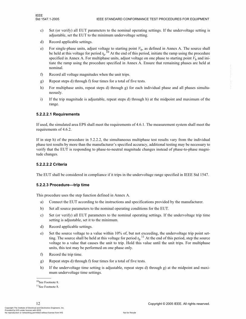
c) Set (or verify) all EUT parameters to the nominal operating settings. If the undervoltage setting isadjustable, set the EUT to the minimum undervoltage setting.
d) Record applicable settings.
e) For single-phase units, adjust voltage to starting point Vb, as defined in Annex A. The source shallbe held at this voltage for period th.10 At the end of this period, initiate the ramp using the procedurespecified in Annex A. For multiphase units, adjust voltage on one phase to starting point Vb and ini-tiate the ramp using the procedure specified in Annex A. Ensure that remaining phases are held atnominal.
f) Record all voltage magnitudes when the unit trips.
g) Repeat steps d) through f) four times for a total of five tests.
h) For multiphase units, repeat steps d) through g) for each individual phase and all phases simulta-neously.
i) If the trip magnitude is adjustable, repeat steps d) through h) at the midpoint and maximum of therange.
5.2.2.2.1 Requirements
If used, the simulated area EPS shall meet the requirements of 4.6.1. The measurement system shall meet therequirements of 4.6.2.
If in step h) of the procedure in 5.2.2.2, the simultaneous multiphase test results vary from the individualphase test results by more than the manufacturer’s specified accuracy, additional testing may be necessary toverify that the EUT is responding to phase-to-neutral magnitude changes instead of phase-to-phase magni-tude changes.
5.2.2.2.2 Criteria
The EUT shall be considered in compliance if it trips in the undervoltage range specified in IEEE Std 1547.
5.2.2.3 Procedure—trip time
This procedure uses the step function defined in Annex A.
a) Connect the EUT according to the instructions and specifications provided by the manufacturer.
b) Set all source parameters to the nominal operating conditions for the EUT.
c) Set (or verify) all EUT parameters to the nominal operating settings. If the undervoltage trip timesetting is adjustable, set it to the minimum.
d) Record applicable settings.
e) Set the source voltage to a value within 10% of, but not exceeding, the undervoltage trip point set-ting. The source shall be held at this voltage for period th.11 At the end of this period, step the sourcevoltage to a value that causes the unit to trip. Hold this value until the unit trips. For multiphaseunits, this test may be performed on one phase only.
f) Record the trip time.
g) Repeat steps d) through f) four times for a total of five tests.
h) If the undervoltage time setting is adjustable, repeat steps d) through g) at the midpoint and maxi-mum undervoltage time settings.
10See Footnote 8.11See Footnote 8.
Copyright The Institute of Electrical and Electronics Engineers, Inc. Provided by IHS under license with IEEE
Not for ResaleNo reproduction or networking permitted without license from IHS
--`,,```,,,,````-`-`,,`,,`,`,,`---

IEEEINTERCONNECTING DISTRIBUTED RESOURCES WITH ELECTRIC POWER SYSTEMS Std 1547.1-2005
Copyright © 2005 IEEE. All rights reserved. 13
5.2.2.3.1 Requirements
If used, the simulated area EPS shall meet the requirements of 4.6.1. The measurement system shall meet therequirements of 4.6.2.
5.2.2.3.2 Criteria
The EUT shall be considered in compliance if the measured trip time is within the clearing time for the und-ervoltage range specified in IEEE Std 1547.
5.3 Response to abnormal frequency conditions
5.3.1 Test for overfrequency
5.3.1.1 Purpose
The purpose of this test is to verify that the DR interconnection component or system ceases to energize thearea EPS as specified in IEEE Std 1547 with respect to overfrequency conditions. This test determines themagnitude and trip time for each overfrequency function.
5.3.1.2 Procedure—magnitude
This procedure uses the ramp function defined in Annex A. a) Connect the EUT according to the instructions and specifications provided by the manufacturer.b) Set all source parameters to the nominal operating conditions for the EUT.c) Set (or verify) all EUT parameters to the nominal operating settings. If the overfrequency setting is
adjustable, set the EUT to the minimum overfrequency setting. d) Record applicable settings.e) Adjust the source frequency to starting point fb. The source shall be held at this frequency for period
th.12 At the end of this period, initiate the ramp using the procedure specified in Annex A. f) Record the frequency at which the unit trips.g) Repeat steps d) through f) four times for a total of five tests. h) If the overfrequency setting is adjustable, repeat steps d) through g) at the midpoint and maximum
overfrequency settings.
5.3.1.2.1 Requirements
If used, the simulated area EPS shall meet the requirements of 4.6.1. The measurement system shall meet therequirements of 4.6.2.
5.3.1.2.2 Criteria
The EUT shall be considered in compliance if it trips in the overfrequency range specified in IEEE Std 1547.
5.3.1.3 Procedure—trip time
This procedure uses the step function defined in Annex A. a) Connect the EUT according to the instructions and specifications provided by the manufacturer.
12See Footnote 8.
Copyright The Institute of Electrical and Electronics Engineers, Inc. Provided by IHS under license with IEEE
Not for ResaleNo reproduction or networking permitted without license from IHS
--`,,```,,,,````-`-`,,`,,`,`,,`---

IEEEStd 1547.1-2005 IEEE STANDARD CONFORMANCE TEST PROCEDURES FOR EQUIPMENT
14 Copyright © 2005 IEEE. All rights reserved.
b) Set all source parameters to the nominal operating conditions for the EUT.c) Set (or verify) all EUT parameters to the nominal operating settings. If the overfrequency trip time
setting is adjustable, set it to the minimum. d) Record applicable settings.e) Set the source frequency to a value within 1% of, but not exceeding, the overfrequency trip point
setting. The source shall be held at this frequency for period th.13 At the end of this period, step thesource frequency to a value that causes the unit to trip. Hold this value until the unit trips.
f) Record the trip time.g) Repeat steps d) through f) four times for a total of five tests. h) If the overfrequency time setting is adjustable, repeat steps d) through g) at the midpoint and maxi-
mum overfrequency time settings.
5.3.1.3.1 Requirements
If used, the simulated area EPS shall meet the requirements of 4.6.1. The measurement system shall meet therequirements of 4.6.2.
5.3.1.3.2 Criteria
The EUT shall be considered in compliance if the measured trip time is within the clearing time for the over-frequency range specified in IEEE Std 1547.
5.3.1.3.3 Comments
For some EUT, the step size past the frequency trip limit should be as small as possible to reduce falseresults. Large frequency step changes can interfere with EUT phase lock loop operation.
5.3.2 Test for underfrequency
5.3.2.1 Purpose
The purpose of this test is to verify that the DR interconnection component or system ceases to energize thearea EPS as specified in IEEE Std 1547 with respect to underfrequency conditions. This test determines themagnitude and trip time for each underfrequency function.
5.3.2.2 Procedure—magnitude
This procedure uses the ramp function defined in Annex A. a) Connect the EUT according to the instructions and specifications provided by the manufacturer.b) Set all source parameters to the nominal operating conditions for the EUT.c) Set (or verify) all EUT parameters to the nominal operating settings. If the underfrequency setting is
adjustable, set the EUT to the minimum underfrequency setting. d) Record applicable settings.e) Adjust the source frequency to starting point fb. The source shall be held at this frequency for period
th.14 At the end of this period, initiate the ramp using the procedure specified in Annex A. f) Record the frequency at which the unit trips.g) Repeat steps d) through f) four times for a total of five tests.
13See Footnote 8.14See Footnote 8.
Copyright The Institute of Electrical and Electronics Engineers, Inc. Provided by IHS under license with IEEE
Not for ResaleNo reproduction or networking permitted without license from IHS
--`,,```,,,,````-`-`,,`,,`,`,,`---

IEEEINTERCONNECTING DISTRIBUTED RESOURCES WITH ELECTRIC POWER SYSTEMS Std 1547.1-2005
Copyright © 2005 IEEE. All rights reserved. 15
h) If the underfrequency setting is adjustable, repeat steps d) through g) at the midpoint and maximumunderfrequency settings.
5.3.2.2.1 Requirements
If used, the simulated area EPS shall meet the requirements of 4.6.1. The measurement system shall meet therequirements of 4.6.2.
5.3.2.2.2 Criteria
The EUT shall be considered in compliance if it trips in the underfrequency range specified in IEEEStd 1547.
5.3.2.3 Procedure—trip time
This procedure uses the step function defined in Annex A. a) Connect the EUT according to the instructions and specifications provided by the manufacturer.b) Set all source parameters to the nominal operating conditions for the EUT.c) Set (or verify) all EUT parameters to the nominal operating settings. If the underfrequency trip time
setting is adjustable, set it to the minimum. d) Record applicable settings.e) Set the source frequency to a value within 1% of, but not exceeding, the underfrequency trip point
setting. The source shall be held at this frequency for period th.15 At the end of this period, step thesource frequency to a value that causes the unit to trip. Hold this value until the unit trips.
f) Record the trip time.g) Repeat steps d) through f) four times for a total of five tests. h) If the underfrequency time setting is adjustable, repeat steps d) through g) at the midpoint and maxi-
mum underfrequency time settings.
5.3.2.3.1 Requirements
If used, the simulated area EPS shall meet the requirements of 4.6.1. The measurement system shall meet therequirements of 4.6.2.
5.3.2.3.2 Criteria
The EUT shall be considered in compliance if the measured trip time is within the clearing time for theunderfrequency range specified in IEEE Std 1547.
5.3.2.3.3 Comments
For some EUT, the step size past the frequency trip limit should be as small as possible to reduce falseresults. Large frequency step changes can interfere with EUT phase lock loop operation.
5.4 Synchronization
The purpose of the tests in this subclause is to demonstrate that the EUT will accurately and reliably syn-chronize to the area EPS according to the requirements of IEEE Std 1547. Separately excited induction gen-erators shall be tested using the procedure for synchronous generators.
15See Footnote 8.
Copyright The Institute of Electrical and Electronics Engineers, Inc. Provided by IHS under license with IEEE
Not for ResaleNo reproduction or networking permitted without license from IHS
--`,,```,,,,````-`-`,,`,,`,`,,`---

IEEEStd 1547.1-2005 IEEE STANDARD CONFORMANCE TEST PROCEDURES FOR EQUIPMENT
16 Copyright © 2005 IEEE. All rights reserved.
Two basic test methods are provided:
— Method 1 verifies that a synchronization control function will cause the paralleling device to closeonly when key synchronization parameters are within allowable limits.
— Method 2 determines the magnitude of the synchronization startup current.
Equipment that can generate voltage independently of the area EPS and is thus capable of out-of-phase par-alleling with the area EPS (e.g., a synchronous generator or inverter operating in a stand-alone mode) istested to verify compliance of its synchronizing capability using Method 1.
Equipment that utilizes energy from the area EPS service to begin operation (e.g., an induction generator)and that may draw high current levels is tested to determine the synchronization current using Method 2.Equipment that generates a voltage inherently synchronized to the area EPS is also tested to determine thesynchronization current using Method 2. This current value can then be used along with area EPS imped-ance at a specific location to estimate the maximum voltage fluctuation related to synchronization.
The EUT addressed in these procedures includes a wide range of capabilities, ranging from discrete compo-nents providing control and protection functions to complete generator equipment facilities. The intent ofthe testing requirement in this subclause is that the user identify the procedure most appropriate for the par-ticular situation and use that procedure to validate equipment performance. IEEE Std 1547 requires thatwhen paralleling with the area EPS, the DR should not cause excessive voltage fluctuation. Therefore, whenin doubt, Method 2 should be used. Some equipment with multiple operating modes may have to be testedusing both of the basic methods.
Three variations of Method 1 are provided. The first variation (5.4.1) assumes a simulated generator sourceand would be performed, for example, on a discrete relay or multifunction controller with synchronizationcontrol function. The second variation (5.4.2) assumes a real generator source is used. The third variation(5.4.3) is designed for testing of equipment in which the synchronizing functions cannot be switched off orthe sensing voltage cannot be conveniently disconnected.
5.4.1 Synchronization control function test using simulated sources (Method 1, variation 1)
5.4.1.1 Purpose
The purpose of these tests is to demonstrate that interconnection equipment will synchronize to the area EPSacross an open paralleling device (e.g., a power circuit breaker), within allowable limits of voltage, fre-quency, and phase-angle difference before the paralleling device is allowed to close. The procedure isintended for a discrete or multifunction interconnection control device that includes a synchronization func-tion and may be used in laboratory tests with simulated generator equipment and a simulated area EPSsource.
If the EUT does not include a paralleling device, the acceptability of the ICS for a specific site depends onthe speed of operation of the paralleling device to be used with the EUT.
5.4.1.2 Procedure
a) Connect the EUT according to the instructions and specifications provided by the manufacturer.
b) Connect the test equipment to monitor the paralleling device close command, the phase relationshipbetween simulated generator output and area EPS sources, the frequency of each source, and thevoltage of each source.
c) Set simulated area EPS source to operate at nominal voltage and frequency. Record applicablesettings.
Copyright The Institute of Electrical and Electronics Engineers, Inc. Provided by IHS under license with IEEE
Not for ResaleNo reproduction or networking permitted without license from IHS
--`,,```,,,,````-`-`,,`,,`,`,,`---
IEEEINTERCONNECTING DISTRIBUTED RESOURCES WITH ELECTRIC POWER SYSTEMS Std 1547.1-2005
Copyright © 2005 IEEE. All rights reserved. 17
d) Demonstrate that the equipment will not close outside of the voltage acceptance range defined inIEEE Std 1547, but will close within that acceptance range. By holding the voltage and frequency ofthe simulated area EPS source at constant nominal values and varying the voltage of the generatorsource, the test will demonstrate that the EUT will not initiate closing outside of acceptable rangesof voltage and will close within acceptable ranges. The test will demonstrate that the EUT functionsproperly both from a low voltage that is raised to within an acceptable level and from a high voltagethat is lowered to within an acceptable level. The following process may be used for testing thevoltage:1) Set the voltage and frequency of the area EPS source to nominal values. 2) Set the voltage of the simulated generator source to a level above the area EPS source voltage
so that the voltage difference is outside the acceptance range, but the generator voltage is belowthe overvoltage trip limit of the EUT (if so equipped). The voltage difference should be at leasttwice the manufacturer’s stated accuracy.16
3) Set and hold the frequency of the simulated generator source to that of the simulated area EPSso that frequency difference and phase angle17 are within the limits allowed by the require-ments of IEEE Std 1547. Include an allowance for EUT accuracy so that frequency and phaseangle do not inadvertently keep the EUT from initiating a paralleling device closure.
4) Verify for a period of at least 3 min that the EUT does not initiate closing. 5) Gradually reduce the generator source voltage until the voltage difference is within the accep-
tance values of IEEE Std 1547 including an allowance for EUT accuracy. The voltage ramprate should be controlled to allow reliable indication of the point at which paralleling deviceclosure is initiated. A procedure for determining ramp rates is described in Annex A.
6) Record the voltage and frequency for the area EPS and generator sources, as well as the volt-age, frequency, and phase-angle differences between the two sources at the point at which theEUT initiates paralleling device closure.
7) Repeat steps a) through f) four times for a total of five sets of readings.8) Repeat steps a) through g) except with the initial simulated generator source voltage set at a
level below the area EPS source voltage so that the voltage difference is outside the acceptancerange, but the generator voltage is above the undervoltage trip limit of the EUT.
e) Demonstrate that the equipment will not close outside of the frequency and phase-angle acceptancerange defined in IEEE Std 1547, but will close within that acceptance range. By holding the voltageand frequency of the area EPS source constant and varying the frequency of the generator source,the test will demonstrate that the EUT will not initiate paralleling device closure outside of accept-able ranges of frequency difference and phase angle and will initiate paralleling device closurewithin acceptable ranges. The test will demonstrate that the EUT functions properly starting fromboth a low frequency that is raised to within an acceptable level and from a high frequency that islowered to within an acceptable level.1) Set the voltage and frequency of the area EPS source to nominal values. Set the generator
source voltage to that of the area EPS.2) Set the frequency of the simulated generator source to a level above the area EPS source fre-
quency so that the frequency difference is outside the acceptance range, but the generator fre-quency is below the overfrequency trip limit of the EUT (if so equipped). The frequencydifference should be at least twice the stated accuracy of the EUT.
3) Set and hold the voltage of the simulated generator source to that of the simulated area EPS sothat voltage difference is within the limits allowed by the requirements of IEEE Std 1547.Include an allowance for EUT accuracy so that voltage difference does not inadvertently keepthe EUT from initiating a paralleling device closure.
16If the EUT stated measurement accuracy is 1%, the initial voltage difference should be at least 2% greater than the allowable limit.17If the generator source frequency and utility source frequency are not identical, phase angle will periodically be within allowablelimits.
Copyright The Institute of Electrical and Electronics Engineers, Inc. Provided by IHS under license with IEEE
Not for ResaleNo reproduction or networking permitted without license from IHS
--`,,```,,,,````-`-`,,`,,`,`,,`---
IEEEStd 1547.1-2005 IEEE STANDARD CONFORMANCE TEST PROCEDURES FOR EQUIPMENT
18 Copyright © 2005 IEEE. All rights reserved.
4) Verify for a period of at least 3 min that the EUT does not initiate paralleling device closure. 5) Gradually reduce the generator source frequency until the frequency difference is within the
acceptance values of IEEE Std 1547 including an allowance for EUT accuracy. The frequencyramp rate should be controlled to allow reliable indication of both the frequency and phaseangle at which paralleling device closure is initiated. A procedure for determining ramp rates isdescribed in Annex A.
6) Record the voltage and frequency for the area EPS and generator sources, as well as the volt-age, frequency, and phase-angle differences between the two sources at the point at which theEUT initiates paralleling device closure.
7) Repeat steps a) through f) four times for a total of five sets of readings.8) Repeat steps a) through g) except with the initial simulated generator source frequency set at a
level below the area EPS source frequency so that the frequency difference is outside theacceptance range, but the generator frequency is above the underfrequency trip limit of theEUT.
5.4.1.3 Requirements
Programmable arbitrary waveform generators (multiphase as necessary) may be used to provide simulatedgenerator and area EPS voltage waveforms. The waveform generator will provide voltage and frequencysignals in a form compatible with the EUT.
Simulated generator voltage and frequency control will come either from the EUT or, for passive devices,from a control computer programmed to provide the desired waveforms.
Equipment steady-state operating performance shall meet the manufacturer’s standards for speed and volt-age stability at no load for at least 15 min.
5.4.1.4 Criteria
The testing shall demonstrate that the equipment complies with the requirements of IEEE Std 1547 for syn-chronization parameter limits.
Test results shall demonstrate that the EUT will not initiate closure out of range for any parameter duringany test.
5.4.1.5 Comments
Since the EUT in this test procedure may not incorporate a paralleling device, the documentation shouldnote that, when applied, the phase angle at the instant of closing would be different from what is recordedduring this test due to the closing time required for the anticipated paralleling device. The EUT may incor-porate provisions to allow compensation for paralleling device operation time.
If parallel device closing time compensation was used, verify that the synchronization device accurately pre-dicted the proper closing angle prior to the specified phase-angle window. Following is a samplecalculation:
Given:paralleling device closing time = 5 cyclesfrequency differential at time of parallel device close command = 0.10 Hzmaximum phase-angle window = 10�
Then:phase rotation rate = frequency differential × 360� = 0.10 Hz × 360� = 36�s–1
Copyright The Institute of Electrical and Electronics Engineers, Inc. Provided by IHS under license with IEEE
Not for ResaleNo reproduction or networking permitted without license from IHS
--`,,```,,,,````-`-`,,`,,`,`,,`---
IEEEINTERCONNECTING DISTRIBUTED RESOURCES WITH ELECTRIC POWER SYSTEMS Std 1547.1-2005
Copyright © 2005 IEEE. All rights reserved. 19
paralleling device closing time = 5 cycles @ 60 Hz = 0.0833 spredictive closing angle = 36�s–1 × 0.0833 s = 3�
Therefore, if the maximum allowable phase angle at paralleling device closure is 10� and the equipment isapproaching synchronization, the initiation point could be 10� + 3� = 13�. If the equipment was movingaway from synchronization, maximum deviation at initiation would be 10� – 3� = 7�.
5.4.2 Synchronization control function test using actual generator equipment (Method 1, variation 2)
5.4.2.1 Purpose
The purpose of these tests is to demonstrate that synchronous generator equipment will accurately and reli-ably synchronize to the area EPS across an open paralleling device (e.g., a power circuit breaker), accordingto the requirements of IEEE Std 1547.
These procedures may also be used with separately excited induction equipment or with inverter equipmentthat is able to operate in isolation from the area EPS and to resynchronized with the area EPS.
5.4.2.2 Procedure
a) Connect the EUT according to the instructions and specifications provided by the manufacturer.Installation must include verification of the ratings, phasing, and connection of the current trans-formers (CTs) and voltage transformers (VTs) (if used) in the system that provides input to the con-trol and protection functions.
b) Connect the test equipment to monitor the paralleling device close command, the phase relationshipbetween sources, the frequency of each source, and all phases of the voltage of the generator and ofthe area EPS.
c) Verify that the EUT is operating at a stable voltage and frequency. Set equipment to operate at ratedvoltage and frequency. Verify that the equipment operates within the frequency and voltage regula-tion specifications of the manufacturer while operating in isolation from the area EPS. Stabilityshould be verified at various load levels up to the maximum that it will be required to carry. Recordapplicable settings, and record voltage and frequency regulation performance.
d) Measure and record the closing time of the paralleling device. Repeat four times for a total of fivetests.
e) Set the generator to the nominal frequency and voltage of the area EPS. Disable paralleling deviceclosure and initiate synchronizing action. Verify that the synchronizing function will correctly oper-ate to close the paralleling device when the generator is properly synchronized. If the parallelingdevice includes a test position that does not allow connection to the area EPS, use of the test positionto verify paralleling device operation is acceptable.
f) Enable paralleling device closing.g) Demonstrate that the equipment will not close outside of the allowed acceptance range for voltage
and will close within the voltage range values required by IEEE Std 1547. The required processholds the frequency of the generator source constant and nearly identical to the area EPS source and,by varying the voltage, will demonstrate that the equipment will not initiate closing out of accept-able ranges of voltage, and will close within acceptable parameters. The test will demonstrate thatthe equipment functions properly both from a low voltage that is raised to an acceptable level, andfrom a high voltage that is lowered to within acceptable range. The following process may be used(at various points in the following procedure, it may be necessary to reset various parameters toproceed):1) If applicable, disable the synchronizing function.
Copyright The Institute of Electrical and Electronics Engineers, Inc. Provided by IHS under license with IEEE
Not for ResaleNo reproduction or networking permitted without license from IHS
--`,,```,,,,````-`-`,,`,,`,`,,`---
IEEEStd 1547.1-2005 IEEE STANDARD CONFORMANCE TEST PROCEDURES FOR EQUIPMENT
20 Copyright © 2005 IEEE. All rights reserved.
2) Set and hold the voltage of the generator to a level so that the voltage difference is outside theacceptance range, but within the acceptable voltage and frequency operating range of the ICS.The level selected should be higher than the acceptance range and high enough so that the accu-racy of the EUT will not inadvertently initiate operation.
3) Set and hold the frequency of the generator source to that of the area EPS. Maintain the phaseangle to within the acceptance limits of IEEE Std 1547.
4) Verify for a period of at least 3 min that the interconnection equipment does not initiate closing.5) Gradually reduce the voltage difference to within the acceptance values of IEEE Std 1547. The
rate of ramp of the voltage parameter should be controlled to a value that allows reliable indica-tion of the initiation point. A procedure for determining ramp rates is described in Annex A.Record the voltage differential at the time of initiation of closure.
6) Repeat steps a) through e) except with the initial generator voltage below the area EPS sourcevoltage. The level should be lower than the acceptance range and should be selected so that theaccuracy of the EUT will not inadvertently initiate operation.
h) Demonstrate that the equipment will not close outside of the acceptance range due to improper fre-quency sensing or phase-angle sensing and will close within the values of IEEE Std 1547. Therequired process holds the voltage of the simulated generator source constant and nearly identical tothe area EPS source and, by varying the frequency, will demonstrate that the equipment will not ini-tiate closing out of acceptable ranges of frequency and phase angle and will close within acceptableparameters. The test will demonstrate that the equipment functions properly both from a low fre-quency that is raised to an acceptable level and from a high frequency that is lowered to withinacceptable range. The following process may be used:1) Set the frequency of the generator source to a level so that the frequency difference is outside
the acceptance range, but within the acceptable voltage and frequency operating range of theICS. The level selected should be higher than the acceptance range and high enough so that theaccuracy of the EUT will not inadvertently initiate operation.
2) Set the voltage of the generator source to that of the area EPS source. 3) Hold the voltage and frequency constant. Verify for a period of at least 3 min that the intercon-
nection equipment does not initiate closing. (This step may require disabling the automaticsynchronizing function of the generator.)
4) Gradually reduce the frequency difference to within the acceptance values of IEEE Std 1547.The ramp rate of the frequency parameter should be controlled to a value that allows reliableindication of the initiation point. A procedure for determining ramp rates is described inAnnex A. Record the frequency differential and phase-angle deviation at the time of initiationof closure.
5) Repeat steps a) through d) except with the initial generator frequency below the area EPSsource frequency. The level should be lower than the acceptance range and should be selectedso that the accuracy of the EUT will not inadvertently initiate operation.
i) Repeat this test procedure four times for a total of five tests.
5.4.2.3 Requirements
If used, the simulated area EPS shall meet the requirements of 4.6.1.
If an actual area EPS source is used, the area EPS source must remain within the undervoltage, overvoltage,underfrequency, and overfrequency trip limits defined by IEEE Std 1547.
Frequency should be set at nominal and maintained within ± 0.05 Hz.
The measurement system shall meet the requirements of 4.6.2.
Copyright The Institute of Electrical and Electronics Engineers, Inc. Provided by IHS under license with IEEE
Not for ResaleNo reproduction or networking permitted without license from IHS
--`,,```,,,,````-`-`,,`,,`,`,,`---

IEEEINTERCONNECTING DISTRIBUTED RESOURCES WITH ELECTRIC POWER SYSTEMS Std 1547.1-2005
Copyright © 2005 IEEE. All rights reserved. 21
5.4.2.4 Criteria
The testing shall demonstrate that the equipment complies with the requirements of IEEE Std 1547 for syn-chronizing performance. IEEE Std 1547 presumes that the voltage fluctuation requirement is met bysuccessful completion of these tests.
Test results shall demonstrate that contacts will not close out of range during any test.
5.4.2.5 Comments
There are a large number of potential application issues that affect the performance of the synchronizingequipment. In particular, phase rotation of generator sets relative to the grid, phasing of potential transform-ers serving protection and control equipment, and many other factors. Therefore, it is critical that carefulattention be paid to the manufacturer’s installation instructions and system design drawings to avoid out-of-phase paralleling of the generator equipment to the area EPS.
5.4.3 Synchronization control function test for equipment with no synchronizing disable capability (Method 1, variation 3)
5.4.3.1 Purpose
The purpose of this test is to demonstrate that the EUT will synchronize to the area EPS across an openparalleling device, within allowable limits of voltage, frequency, and phase-angle difference before the par-alleling device is allowed to close. The procedure is intended for equipment that automatically synchronizeswhen a reference voltage source is available, maintains synchronization prior to connecting with the areaEPS, and does not include a means to disable or disconnect the synchronizing function.
5.4.3.2 Procedure
a) Install and adjust the EUT according to the manufacturer’s recommendations and specifications.
b) Connect test equipment to monitor the paralleling device close command, the phase relationshipbetween EUT output and area EPS sources, the frequency difference, voltage difference, and phaseangle between the sources.
c) Set simulated area EPS source to operate at nominal voltage and frequency. Record applicablesettings.
d) Disconnect the area EPS from the EUT.
e) Enable all monitoring equipment. Reapply the area EPS and record all required parameters (i.e.,voltage, frequency, and phase-angle differences) during the paralleling operation.
f) Repeat this test procedure four times for a total of five tests.
5.4.3.3 Requirements
If used, the simulated area EPS shall meet the requirements of 4.6.1. The measurement system shall meet therequirements of 4.6.2.
5.4.3.4 Criteria
The testing shall demonstrate that the equipment complies with the requirements of IEEE Std 1547 for syn-chronization parameter limits.
Copyright The Institute of Electrical and Electronics Engineers, Inc. Provided by IHS under license with IEEE
Not for ResaleNo reproduction or networking permitted without license from IHS
--`,,```,,,,````-`-`,,`,,`,`,,`---
IEEEStd 1547.1-2005 IEEE STANDARD CONFORMANCE TEST PROCEDURES FOR EQUIPMENT
22 Copyright © 2005 IEEE. All rights reserved.
5.4.4 Startup current measurement (Method 2)
5.4.4.1 Purpose
The purpose of these tests is to determine the maximum startup (in-rush) current drawn by an EUT (e.g., aline-excited induction generator) or by inverter equipment that does not produce output voltage at the timeof connecting to the area EPS. The results of this test may be used along with information for the proposedlocation to verify that the EUT will not violate the synchronizing or flicker requirements of IEEE Std 1547as installed.
5.4.4.2 Procedure
Induction generator equipment may be evaluated using NEMA MG-1. (Manufacturer’s data are acceptableif available and directly applicable based on the application voltage level.)
Induction generator equipment or inverter equipment may be evaluated using the following procedure:
a) Set up the EUT according to the manufacturer’s specifications connected to a simulated or actualarea EPS.
b) The input power source to the EUT shall be capable of providing at least 120% of rated input powerand any normal startup transients.
c) EUT startup shall follow the manufacturer’s specified procedure.
d) Begin with the EUT shutdown.
e) Enable monitoring equipment to record area EPS voltages on all phases (line-to-line and line-to-neutral if it can be connected in that configuration) and to record EUT output current on all phases.
f) Initiate a normal EUT startup procedure.
g) Repeat the test nine times for a total of ten tests.18
h) For each test, calculate the startup current. The startup current is the maximum value of root-mean-square (rms) current calculated over any consecutive 5-cycle window during the startup process.The EUT maximum startup current is the maximum value of the startup current obtained on anyphase in any of the ten tests.
i) Document the impedance of the source used on the test.19
5.4.4.3 Requirements
If used, the simulated area EPS shall meet the requirements of 4.6.1.
The measurement system shall meet the requirements of 4.6.2. Voltage and current waveform measurementsshall be recorded at a sample rate of at least 600 Hz per channel to provide at least 10 samples per cycle.
5.4.4.4 Criteria
This test determines the magnitude of current drawn (or sourced) by the EUT at startup so that voltage fluc-tuation (flicker) calculations can be completed for a specific site. This is a characterization test—there are nospecific pass/fail criteria except as applied at a specific site.
18The number of tests was selected to assure that a maximum value is obtained.19The Thevenin impedance of the area EPS will have a significant effect on the value of the flicker. An infinite bus will create lowflicker values while a high impedance system will result in high flicker values. Impedance of the source can be determined by calcula-tions based on the Thevenin impedance (e.g., source transformer and wiring) or empirically determined by using a load large enough tocause a voltage drop.
Copyright The Institute of Electrical and Electronics Engineers, Inc. Provided by IHS under license with IEEE
Not for ResaleNo reproduction or networking permitted without license from IHS
--`,,```,,,,````-`-`,,`,,`,`,,`---

IEEEINTERCONNECTING DISTRIBUTED RESOURCES WITH ELECTRIC POWER SYSTEMS Std 1547.1-2005
Copyright © 2005 IEEE. All rights reserved. 23
The value reported for the EUT shall be the highest of the ten tests. A graphical representation of the time-current characteristic along with the calculated startup current shall be included in the test report.
5.5 Interconnection integrity
5.5.1 Protection from electromagnetic interference (EMI) test
5.5.1.1 Purpose
The purpose of these tests is to determine the EUT’s protection from EMI and to confirm that the results arein compliance with IEEE Std 1547.
5.5.1.2 Procedure
The interconnection equipment of the EUT shall be tested in accordance with IEEE Std C37.90.2. This testshall be applied to one parameter and trip function representative of the EUT utility protective function mea-surement system.
5.5.1.3 Criteria
The influence of EMI shall not result in a change in state or misoperation of the interconnection functions ofthe EUT.
5.5.2 Surge withstand performance test
5.5.2.1 Purpose
The purpose of this test is to verify the level of surge withstand protection specified by the manufacturer ofthe EUT. The EUT shall be tested to verify the level of surge withstand protection as specified by the manu-facturer and in accordance with IEEE Std C62.41.2 and/or IEEE Std C37.90.1, as applicable.
5.5.2.2 Procedure
The manufacturer shall specify the location category and exposure level of the tests required by IEEE StdC62.41.2 and/or IEEE Std C37.90.1.
a) Apply IEEE Std C37.90.1 to test appropriate EUT external signal and control circuits.
b) Apply IEEE Std C62.41.2 and IEEE Std C62.45 to test appropriate EUT power circuits.
The EUT shall be tested in all normal operating modes in accordance with IEEE Std C62.45 forequipment rated less than or equal to 1000 V to confirm that the surge withstand capability is met byusing the selected test level(s) from IEEE Std C62.41.2. The test should be conducted while the EUTis operating under nominal power unless it can be shown that the surge protection is not affected byits operational state. Equipment rated greater than 1000 V shall be tested in accordance with theapplicable standards as designated by the manufacturer or system integrator.
5.5.2.3 Criteria
The results of these tests shall indicate the interconnection functions of the EUT did not fail, did not misop-erate, and did not provide misinformation.
Copyright The Institute of Electrical and Electronics Engineers, Inc. Provided by IHS under license with IEEE
Not for ResaleNo reproduction or networking permitted without license from IHS
--`,,```,,,,````-`-`,,`,,`,`,,`---
IEEEStd 1547.1-2005 IEEE STANDARD CONFORMANCE TEST PROCEDURES FOR EQUIPMENT
24 Copyright © 2005 IEEE. All rights reserved.
5.5.3 Dielectric test for paralleling device
The following test is for EUT that operate at 1000 V or less. For systems over 1000 V, the EUT shall betested in accordance with the power frequency dielectric withstand rating specified in Table 4 of ANSIC37.06 and the procedures specified in 4.4.3.1 of IEEE Std C37.09.
5.5.3.1 Purpose
This test determines if the paralleling device of the EUT, while at normal operating temperature, can with-stand for 1 min without breakdown the application of an ac rms test potential of 1000 V plus 220% of thenominal ac rms voltage.
5.5.3.2 Procedure
The unit is to be tested using a 500 VA or larger capacity transformer or dielectric tester, the output voltageof which is variable. The applied potential is to be increased from zero until the required test level is reachedand is to be held at that level for 60 s. The increase in applied potential is to be at a substantially uniform rateas rapid as is consistent with correct indication of its value by a voltmeter.
— Exception 1: When a voltmeter is connected across the output circuit to directly indicate the testpotential, the transformer is not required to be rated 500 VA or more.
— Exception 2: A dc test voltage of 220% of the nominal ac peak voltage plus 1400 V may be used forthe dielectric test.
A low-voltage control circuit or a sensor circuit is not required to be connected during the test. Any circuitthat is connected from input to output circuit shall remain connected during the test and provide properisolation.
5.5.3.3 Criteria
The paralleling device of the EUT shall be capable of withstanding the applied test voltage for 60 s. Thereshall be no flashovers during the test, and no damage to the insulation shall be observed after the test.
5.5.3.4 Comments
This test should be applied only to the paralleling device as specified in IEEE Std 1547.
5.6 Limitation of dc injection for inverters without interconnection transformers
5.6.1 Purpose
The purpose of this test is to verify that an inverter that connects to the EPS complies with the dc injectionlimit specified in IEEE Std 1547. This test is conducted on inverters that connect to the EPS without the useof dc-isolation output transformers.
5.6.2 Procedure and data analysis
Operating power levels in this procedure have a tolerance of ± 5%.a) Connect the EUT according to the instructions and specifications provided by the manufacturer.b) Set all source parameters to the nominal operating conditions for the EUT.c) Set (or verify) all EUT parameters to the nominal operating settings.d) Record applicable settings.
Copyright The Institute of Electrical and Electronics Engineers, Inc. Provided by IHS under license with IEEE
Not for ResaleNo reproduction or networking permitted without license from IHS
--`,,```,,,,````-`-`,,`,,`,`,,`---

IEEEINTERCONNECTING DISTRIBUTED RESOURCES WITH ELECTRIC POWER SYSTEMS Std 1547.1-2005
Copyright © 2005 IEEE. All rights reserved. 25
e) Operate the EUT at 33% of its continuous rated output current20 and at rated p.f. Allow the EUT tooperate for at least 5 min prior to taking any test measurements (or until the EUT temperature stabi-lizes). The EUT shall operate at the specified current and p.f. for the duration of the test.
f) At the EUT output, measure the rms voltage, rms current, and dc component (frequency less than 1Hz) of current on all phases. The averaging window for all measurements shall be not less than onecycle and not more than 60 cycles.
g) Record all measurements at a sampling rate of not less than the reciprocal of the selected averagingwindow21 for a period of 5 min.
h) Repeat steps e) through g) with the DR operating at 66% and at a level as close to 100% of its ratedoutput current as practical.
For all output current levels tested, the following data analysis is required:
a) Calculate average values of rms current and voltage on each phase. For each measurement, the aver-age shall include every sample point recorded during the 5 min test period.
b) Verify that the average rms current on each phase is within 5% of the intended test point (33%, 66%,and 100%).
c) Verify that the average rms voltage on each phase is within 5% of the nominal voltage.
d) Calculate average values for the magnitude of the dc component of current on each phase. The aver-age shall be taken of the absolute (unsigned) value of every sample point recorded during the 5 mintest period.
e) For each phase, divide the average dc component magnitude value by the rated output current of theEUT and multiply the result by 100. Record the final calculated values as the percent dc injectioncurrent for each phase.
5.6.3 Requirements
If used, the simulated area EPS shall meet the requirements of 4.6.1 and shall have negligible dc offset.
5.6.4 Criteria
The EUT shall be considered in compliance if all calculated percent dc injection currents are within the limitspecified in IEEE Std 1547.
5.6.5 Comments
This test may be conducted as part of the harmonics test.
If a simulated area EPS is used, a dedicated isolation transformer should be used.
5.7 Unintentional islanding
The unintentional islanding test given in 5.7.1 is universally acceptable for all DR ICSs. ICSs intended foruse solely with synchronous generators may alternatively use the procedures in 5.7.2. Reverse-power func-tion used for detecting an unintentional island shall be tested in accordance with 5.8, instead of the test inthis subclause.
20Use the grid-connected current rating for units that offer stand-alone and grid-connected mode.21For block averaging or moving average filters, the averaging window is the period over which the averages are taken. For other fil-ters, the averaging window is the reciprocal of the filter bandwidth in hertz.
Copyright The Institute of Electrical and Electronics Engineers, Inc. Provided by IHS under license with IEEE
Not for ResaleNo reproduction or networking permitted without license from IHS
--`,,```,,,,````-`-`,,`,,`,`,,`---

IEEEStd 1547.1-2005 IEEE STANDARD CONFORMANCE TEST PROCEDURES FOR EQUIPMENT
26 Copyright © 2005 IEEE. All rights reserved.
This test addresses several EUT output power levels including EUT set power levels and levels limited bythe DR input source.
5.7.1 Unintentional islanding test
5.7.1.1 Purpose
The purpose of this test is to verify that the DR interconnection component or system ceases to energize thearea EPS as specified in IEEE Std 1547 when an unintentional island condition is present. This test deter-mines the trip time for the test conditions specified in 5.7.1.
5.7.1.2 Procedure
This test procedure is designed to be universally applicable to all DRs, regardless of output p.f. Any reactivepower compensation by the EUT should remain on during the test.
Where the EUT manufacturer requires an external or separate transformer, the transformer is to be con-nected between the EUT and resistance, inductance, and capacitance (RLC) load specified in Figure 222 andis to be considered part of the product being tested.
a) For a single-phase EUT, the test circuit shall be configured as shown in Figure 2. The neutralconnection (grounded conductor) of the RLC load, the simulated area EPS, and the EUT shall beunaffected by the operation of switch S3. For a multiphase EUT, the balanced load circuit shown inFigure 2 is to be applied between each phase to neutral for a four-wire configuration or betweenphases for a three-wire configuration. Switch S3, as shown in Figure 2, shall be gang-operated andmulti-pole.
b) Connect the EUT according to the instructions and specifications provided by the manufacturer.c) Set all EUT input source parameters to the nominal operating conditions for the EUT.
22Notes in text, tables, and figures are given for information only and do not contain requirements needed to implement this standard.
EUT
S3
RLCLOAD
S2S1
SimulatedArea EPS
NOTES
1—Switch S1 may be replaced with individual switches on each of the RLC load components.
2—Unless the EUT has a unity output p.f., the reactive power component of the EUT is considered to be a partof the islanding load circuit in the figure.
Figure 2—Unintentional islanding test configuration
Copyright The Institute of Electrical and Electronics Engineers, Inc. Provided by IHS under license with IEEE
Not for ResaleNo reproduction or networking permitted without license from IHS
--`,,```,,,,````-`-`,,`,,`,`,,`---

IEEEINTERCONNECTING DISTRIBUTED RESOURCES WITH ELECTRIC POWER SYSTEMS Std 1547.1-2005
Copyright © 2005 IEEE. All rights reserved. 27
d) Set (or verify) all EUT parameters to the nominal operating settings. e) Set the EUT (including the input source as necessary) to provide 100% of its rated output power.23 f) Record all applicable settings.g) Set the Simulated EPS to the EUT nominal voltage ± 2% and nominal frequency ± 0.1 Hz.h) Adjust the islanding load circuit in Figure 2 to provide a quality factor Qf of 1.0 ± 0.05 (when Qf is
equal to 1.0, the following applies: PqL = PqC = 1.0 × P).24 The value of Qf is to be determined byusing the following equations as appropriate:
or
whereQf is the quality factor of the parallel (RLC) resonant load,R is the effective load resistance (�),C is effective load capacitance (F),L is effective load inductance (H),PqL is the reactive power per phase consumed by the inductive load component (VARS),PqC is the reactive power per phase consumed by the capacitive load component (VARS),P is the real output power per phase of the unit (W),f is frequency.
The inductance and capacitance are to be calculated using the following equations:
whereL is effective load inductance (H),V is the nominal voltage across each phase of the RLC load (V) (for loads connected phase tophase, V is the nominal line voltage; for loads connected phase to neutral, V is the nominalphase voltage),
23EUT provided with or intended for use with specific defined input sources that can not provide the input power range described in thistest shall be tested within the limitations of the specified or supplied input source. Under these circumstances the test may be performedwith the actual source or a simulated source. Test results will be applicable only to the combination of the EUT and specified source,and the test report should reflect this limitation. 24Based on the equation Qf = Tan(ArcCos(d.p.f.)), where d.p.f is the displacement power factor, a Qf of 2.5 is equivalent to an uncor-rected load d.p.f of 0.37, a Qf of 1.8, uncorrected load d.p.f. of 0.48, and a Qf of 1, uncorrected load d.p.f. of 0.707. Area EPS circuitstypically operate above 0.75 d.p.f. in steady-state conditions; therefore, Qf = 1 (d.p.f.=0.707) is below the load d.p.f. that the DR isexpected to be islanded with. For a point of comparison, the current draft of IEC 62116 [B4] uses a Qf of 0.65 (d.p.f. of 0.84). A lowervalue of Q will allow DR manufacturers to use perturbation schemes that are potentially less detrimental to power quality.
Qf R CL----=
QfPqL PqC�
P---------------------------=
L V2
2 �� f� P� Qf�------------------------------------------=
CP Qf�
2 �� f� V2�--------------------------------=
Copyright The Institute of Electrical and Electronics Engineers, Inc. Provided by IHS under license with IEEE
Not for ResaleNo reproduction or networking permitted without license from IHS
--`,,```,,,,````-`-`,,`,,`,`,,`---

IEEEStd 1547.1-2005 IEEE STANDARD CONFORMANCE TEST PROCEDURES FOR EQUIPMENT
28 Copyright © 2005 IEEE. All rights reserved.
P is the real output power per phase of the unit (W),
Qf is the quality factor of the parallel (RLC) resonant load,
C is the effective load capacitance (F),
f is frequency.
The reactive load is balanced so that the resonant frequency f of the island circuit is within theunderfrequency and overfrequency trip settings of the EUT and as close to nominal frequency aspossible.
When tuning for the current balance in this step with a nonunity output p.f. EUT, there will be animbalance between the L and C load components to account for the EUT reactive current. The EUTreactive output current shall be measured and algebraically added to the appropriate reactive loadcomponent when calculating Qf.
i) Close switch S1, switch S2, and switch S3, and wait until the EUT produces the desired power level.
j) Adjust R, L, and C until the fundamental frequency current through switch S3 is less than 2% of therated current of the EUT on a steady-state basis in each phase.25
k) Open switch S3 and record the time between the opening of switch S3 and when the EUT ceases toenergize the RLC load.
l) The test is to be repeated with the reactive load (either capacitive or inductive) adjusted in 1% incre-ments or alternatively with the reactive power output of the EUT adjusted in 1% increments from95% to 105% of the initial balanced load component value. If unit shutdown times are still increas-ing at the 95% or 105% points, additional 1% increments shall be taken until trip times begindecreasing.
m) After reviewing the results of the previous step, the 1% load setting increments that yielded the threelongest trip times shall be subjected to two additional test iterations. If the three longest trip timesoccur at nonconsecutive 1% load setting increments, the additional two iterations shall be run for allload settings in between.
n) Repeat steps d) through m) with the test input source adjusted to limit the EUT output power to 66%.This value is allowed to be between 50% and 95% of rated output power and is intended to evaluatethe EUT at less than full power and under the condition where the available output is determined orlimited by the input source. If the EUT does not provide this mode of operation, then set the EUT tocontrol the output power to the specified level.
o) Repeat steps d) through m) with the EUT output power set via software or hardware to 33% of itsnominal rating with the test input source capable of supplying at least 150% of the maximum inputpower rating of the EUT over the entire range of EUT input voltages. For units that are incapable ofsetting or commanding an output power level, the EUT output power shall be limited via the inputpower source. For units that are incapable of operating at 33%, the EUT shall be tested at the lowestoutput power the EUT will support. This step is intended to evaluate the EUT at low power andunder the condition where the available output is determined or limited by the EUT control setting.If the EUT does not provide this mode of operation, then set the input source to meet the specifiedoutput power level.
5.7.1.3 Requirements
Where the EUT requires a separate test input source to conduct this test, that source shall be capable of sup-plying at least 150% of the maximum input power rating of the EUT over the entire range of EUT inputvoltages.
25Certain anti-islanding algorithms will sufficiently perturb the fundamental frequency current through switch S3 so that the 2% limitcannot be achieved on a continuous basis. Averaging of the rms current over a number of cycles in a manner that captures the quiescentmagnitude of this current shall be utilized for determination of matched load during this quiescent period.
Copyright The Institute of Electrical and Electronics Engineers, Inc. Provided by IHS under license with IEEE
Not for ResaleNo reproduction or networking permitted without license from IHS
--`,,```,,,,````-`-`,,`,,`,`,,`---
IEEEINTERCONNECTING DISTRIBUTED RESOURCES WITH ELECTRIC POWER SYSTEMS Std 1547.1-2005
Copyright © 2005 IEEE. All rights reserved. 29
The RLC load shall be tuned so that the fundamental frequency current through switch S3 is less than 2% ofthe rated current of the unit under test on a steady-state basis in each phase.
The test and measurement equipment shall record each phase current and each phase-to-neutral or phase-to-phase voltage, as appropriate, to determine fundamental frequency real and reactive power flow over theduration of the test. Anti-aliasing filters and sampling frequencies appropriate to the measurement of thefundamental frequency component shall be applied. The minimum measurement accuracy shall be 1% orless of rated EUT nominal output voltage and 1% or less of rated EUT output current.
The equations for Qf are based upon an ideal parallel RLC circuit. For this reason, noninductive resistors,low loss (high Q) inductors, and capacitors with low effective series resistance and effective series induc-tance shall be utilized in the test circuit. Real and reactive power should be instrumented in each of the R, L,and C legs of the load so that these parasitic parameters (and parasitics introduced by variacs or autotrans-formers) are properly accounted for when calculating Qf. Iron core inductors, if used, shall not exceed a cur-rent THD of 2% when operated at nominal voltage. Power ratings of resistors should be conservativelychosen to minimize thermally induced drift in resistance values during the course of the test.
5.7.1.4 Criteria
A test is successful when the DR ceases to energize the test load within the timing requirements of IEEE Std1547 after switch S3 is opened.
If any of these tests results in islanding for longer than the specified time, the unit fails the test.
The actual trip time for each test shall be recorded.
A single failure of any of these tests is considered a failure of the entire test sequence.
5.7.1.5 Comments
An area EPS source means any source capable of maintaining an island within the recommended voltageand frequency window. An engine-generator with voltage and frequency control and without islanding pro-tection can be considered an area EPS source for the purpose of this test. However, because of the uncer-tainty associated with the need to sink both real and reactive power from the DR, this test can be performedmost conveniently with an area EPS connection, rather than a simulated area EPS.
Harmonic currents flow between the area EPS, the capacitor, and the DR, complicating the situation bymaking it appear that current is flowing when the fundamental frequency component of current has beenreduced to zero. Thus it is important, when adjusting inductive and capacitive reactance, to use instrumentsthat can display only the fundamental frequency component of current and power.
It is often advantageous to adjust the inductance first because that measurement is low in harmonics. Thecapacitance is added second so that the voltage is stable when the resistance is added. The resistive parallelload is then added and adjusted. Note that this resistance will be in addition to the resistance that will inher-ently be part of the inductive load.
The maximum recorded trip times may prove useful in area EPS system protection coordination studies andshould be presented with other EUT product literature.
Copyright The Institute of Electrical and Electronics Engineers, Inc. Provided by IHS under license with IEEE
Not for ResaleNo reproduction or networking permitted without license from IHS
--`,,```,,,,````-`-`,,`,,`,`,,`---

IEEEStd 1547.1-2005 IEEE STANDARD CONFORMANCE TEST PROCEDURES FOR EQUIPMENT
30 Copyright © 2005 IEEE. All rights reserved.
5.7.2 Unintentional islanding test for synchronous generators
5.7.2.1 Purpose
The purpose of this test is to verify that a DR interconnection component or system ceases to energize thearea EPS as specified in IEEE Std 1547 when an unintentional island condition is present. This test is forapplications where synchronous generators are connected to the EPS. This test determines the trip time forthe test conditions specified in 5.7.2.
5.7.2.2 Procedure
a) For a single-phase EUT, the test circuit shall be configured as shown in Figure 3. For a three-phaseEUT, the balanced load circuit shown in Figure 3 is to be applied between each phase to neutral fora four-wire configuration or between phases for a three-wire configuration. Switch S1, as shown inFigure 3, shall be gang-operated and three-pole. The grounding of the load and simulated area EPSside of the EUT shall be unaffected by the position of switch S1.
b) Connect the EUT according to the instructions and specifications provided by the manufacturer.
c) Set all source parameters to the nominal operating conditions for the EUT.
d) Set the islanding load circuit in Figure 3 to a real load of 5% (or minimum load as specified by themanufacturer) and unity 1.0 p.f.
e) Record all applicable settings.
f) Adjust the output of the synchronous generator to match the test load in power and p.f. until the fun-damental frequency current through switch S1 is less than 2% of the rated current of the unit undertest on a steady-state basis in each phase. NOTE—Certain anti-islanding algorithms will sufficiently perturb the fundamental frequency current throughswitch S1 so that the 2% limit cannot be achieved on a continuous basis. Averaging of the rms current over anumber of cycles in a manner that captures the quiescent magnitude of this current shall be utilized for determi-nation of matched load during this quiescent period.26
g) Open switch S1 and record the time between the opening of switch S1 and when the EUT ceases toenergize the load.
h) Repeat test four times for a total of five times.
i) Repeat steps d) through h) for the following combinations:
— Maximum real load at unity p.f.
— Maximum real load at rated p.f. lagging
— Maximum real load at rated p.f. leading
5.7.2.3 Requirements
The test and measurement equipment shall record each phase current and each phase-to-neutral or phase-to-phase voltage, as appropriate; to determine fundamental frequency real and reactive power flow over theduration of the test. Anti-aliasing filters and sampling frequencies appropriate to the measurement of thefundamental frequency component shall be applied. The minimum measurement accuracy shall be 1% ofrated EUT nominal output voltage and 1% of rated EUT output current.
26Notes in text, tables, and figures are given for information only and do not contain requirements needed to implement this standard.
Copyright The Institute of Electrical and Electronics Engineers, Inc. Provided by IHS under license with IEEE
Not for ResaleNo reproduction or networking permitted without license from IHS
--`,,```,,,,````-`-`,,`,,`,`,,`---
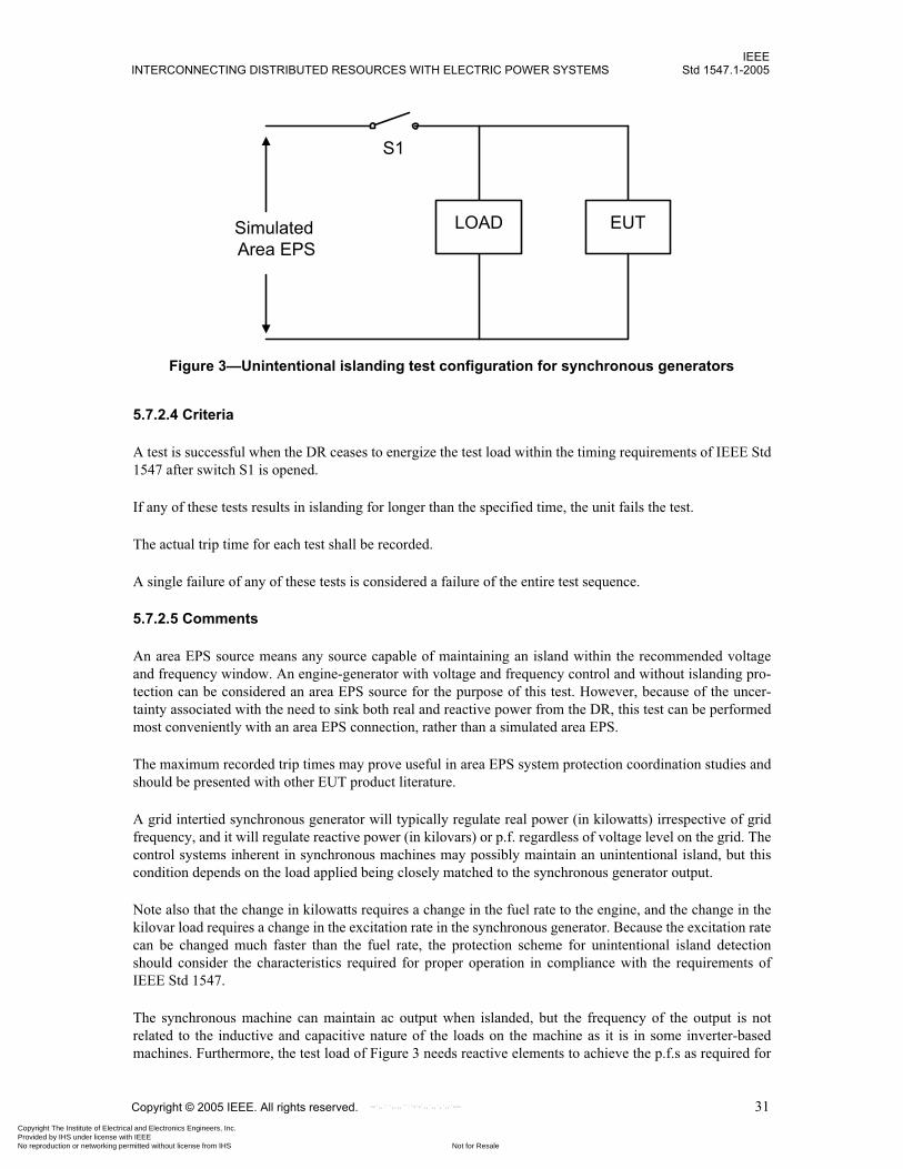
IEEEINTERCONNECTING DISTRIBUTED RESOURCES WITH ELECTRIC POWER SYSTEMS Std 1547.1-2005
Copyright © 2005 IEEE. All rights reserved. 31
5.7.2.4 Criteria
A test is successful when the DR ceases to energize the test load within the timing requirements of IEEE Std1547 after switch S1 is opened.
If any of these tests results in islanding for longer than the specified time, the unit fails the test.
The actual trip time for each test shall be recorded.
A single failure of any of these tests is considered a failure of the entire test sequence.
5.7.2.5 Comments
An area EPS source means any source capable of maintaining an island within the recommended voltageand frequency window. An engine-generator with voltage and frequency control and without islanding pro-tection can be considered an area EPS source for the purpose of this test. However, because of the uncer-tainty associated with the need to sink both real and reactive power from the DR, this test can be performedmost conveniently with an area EPS connection, rather than a simulated area EPS.
The maximum recorded trip times may prove useful in area EPS system protection coordination studies andshould be presented with other EUT product literature.
A grid intertied synchronous generator will typically regulate real power (in kilowatts) irrespective of gridfrequency, and it will regulate reactive power (in kilovars) or p.f. regardless of voltage level on the grid. Thecontrol systems inherent in synchronous machines may possibly maintain an unintentional island, but thiscondition depends on the load applied being closely matched to the synchronous generator output.
Note also that the change in kilowatts requires a change in the fuel rate to the engine, and the change in thekilovar load requires a change in the excitation rate in the synchronous generator. Because the excitation ratecan be changed much faster than the fuel rate, the protection scheme for unintentional island detectionshould consider the characteristics required for proper operation in compliance with the requirements ofIEEE Std 1547.
The synchronous machine can maintain ac output when islanded, but the frequency of the output is notrelated to the inductive and capacitive nature of the loads on the machine as it is in some inverter-basedmachines. Furthermore, the test load of Figure 3 needs reactive elements to achieve the p.f.s as required for
EUT
S1
Simulated Area EPS
LOAD
Figure 3—Unintentional islanding test configuration for synchronous generators
Copyright The Institute of Electrical and Electronics Engineers, Inc. Provided by IHS under license with IEEE
Not for ResaleNo reproduction or networking permitted without license from IHS
--`,,```,,,,````-`-`,,`,,`,`,,`---
IEEEStd 1547.1-2005 IEEE STANDARD CONFORMANCE TEST PROCEDURES FOR EQUIPMENT
32 Copyright © 2005 IEEE. All rights reserved.
step i) of the procedure in 5.7.2.2. Consequently, the testing procedure for unintentional island testing forsynchronous machines is different from the procedure for other DR equipment.
It is possible that the synchronous machine may operate differently at one of its control limits from the wayit operates at others. The test procedure for synchronous machines verifies that the unintentional islandingprotection of the synchronous machine is effective over the operating range of the equipment for both thefuel and the excitation control.
5.8 Reverse power (for unintentional islanding)
IEEE Std 1547 requires DR units to cease to energize the area EPS during unintentional islanding condi-tions. One of the ways in which this requirement may be met is with reverse-power protection. The DRinstallation may contain reverse or minimum import power-flow protection, sensed between the point of DRconnection and the PCC, which will disconnect or isolate the DR if power flow from the area EPS to thelocal EPS reverses or falls below a set threshold.
5.8.1 Reverse-power magnitude test
5.8.1.1 Purpose
This test is performed to characterize the accuracy of the reverse-power protection magnitude setting(s) ofthe EUT. The reverse-power protection accuracy of the EUT shall be specified prior to beginning the tests.
5.8.1.2 Procedures
a) Connect EUT according to the instructions and specifications provided by the manufacturer.
b) Set the source and DR voltages and the DR current(s) to the nominal operating conditions for theEUT.
c) Set (or verify) all EUT parameters to the nominal operating settings (refer to Appendix A for addi-tional detail).
d) Record applicable settings.
e) Referring to the reverse-power magnitude test described in Annex A, adjust the current to startingpoint Ib. Initiate a phase-angle step function from 0� to 180�. The current shall be held at this magni-tude and phase angle for period th.27At the end of this period, initiate the current ramp function.
f) Record the current magnitude when the EUT trips.28
g) Return the current to nominal magnitude IN and phase angle � = 0� (and reset the EUT as necessary).
h) Repeat steps e) through g) four times for a total of five tests.
i) For multiphase systems, repeat steps e) through h) for each phase individually and all phasessimultaneously.
5.8.1.3 Criteria
The EUT is expected to trip within the specified accuracy for all tests. The test results may be used tocharacterize or verify the protection level accuracy relative to manufacturer specifications, interconnectionstandards, periodic verification of calibration, and so on.
27See Footnote 8.28Because the source voltage is 1.0 per unit and the phase relationship between the source voltage and current is 180�, the reverse-power trip magnitude will be directly proportional to the current magnitude at the trip point.
Copyright The Institute of Electrical and Electronics Engineers, Inc. Provided by IHS under license with IEEE
Not for ResaleNo reproduction or networking permitted without license from IHS
--`,,```,,,,````-`-`,,`,,`,`,,`---

IEEEINTERCONNECTING DISTRIBUTED RESOURCES WITH ELECTRIC POWER SYSTEMS Std 1547.1-2005
Copyright © 2005 IEEE. All rights reserved. 33
5.8.2 Reverse-power time test
5.8.2.1 Purpose
This test is performed to characterize the accuracy of the reverse-power time-delay setting(s) of the EUT.The reverse-power protection time-delay accuracy of the EUT shall be specified prior to beginning the tests.
5.8.2.2 Procedures
a) Connect the EUT according to the instructions and specifications provided by the manufacturer.b) Set the source and DR voltages and the DR current(s) to the nominal operating conditions for the
EUT.c) Set (or verify) all EUT parameters to the nominal operating settings (refer to Annex A for additional
detail).d) Record applicable settings.e) Referring to the reverse-power time test described in Annex A, adjust the current to starting point Ib.
Initiate a phase-angle step function from 0� to 180�. The current shall be held at this magnitude andphase angle for period th.29 At the end of this period, initiate the current step function.
f) Record the time between the initiation of the step function and the occurrence of the EUT’s expectedresponse.
g) Return the current to nominal magnitude IN and phase angle � = 0� (and reset the EUT as necessary).h) Repeat steps e) through g) four times for a total of five tests.i) For multiphase systems, repeat steps e) through h) for each phase individually and all phases
simultaneously.
5.8.2.3 Criteria
The EUT is expected to respond within the specified accuracy for all tests. The test results may be used tocharacterize or verify the protection level accuracy relative to manufacturer specifications, interconnectionstandards, periodic verification of calibration, and so on.
5.9 Open phase30
5.9.1 Purpose
The purpose of this test is to verify that the ICS ceases to energize the area EPS upon loss of an individualphase at the PCC or at the point of DR connection.
5.9.2 Procedure
Single-phase two-wire ICSs shall be subjected to steps a) through e) only. Multiphase and single-phasethree-wire ICSs shall be subjected to steps a) through f). If the EUT requires the use of an isolation trans-former, it will be tested with the isolation transformer.
a) Connect the EUT in accordance with the instructions and specifications provided by the manufac-turer through individual phase conductor disconnects on each ungrounded phase to a simulated areaEPS.
b) Set DR and simulated area EPS source parameters to the nominal operating conditions for the EUT.
29See Footnote 8.30This test is intended to demonstrate compliance with the individual phase requirement of the cease-to-energize functionality test ofIEEE Std 1547. It is noted that loss of a phase is a common area EPS occurrence.
Copyright The Institute of Electrical and Electronics Engineers, Inc. Provided by IHS under license with IEEE
Not for ResaleNo reproduction or networking permitted without license from IHS
--`,,```,,,,````-`-`,,`,,`,`,,`---

IEEEStd 1547.1-2005 IEEE STANDARD CONFORMANCE TEST PROCEDURES FOR EQUIPMENT
34 Copyright © 2005 IEEE. All rights reserved.
c) Open one phase conductor disconnect while the EUT is operating at the greater of — 5% of rated output current or — The EUT’s minimum output current.
d) Record the clearing time.e) Repeat steps c) through d) four times for a total of five tests.31
f) Repeat steps c) through e) for all remaining phase conductor disconnects.
5.9.3 Requirements
If used, the simulated area EPS shall meet the requirements of 4.6.1. The measurement system shall meet therequirements of 4.6.2.
5.9.4 Criteria
After the disconnect is opened, the EUT shall cease to energize all output terminals connected to the simu-lated area EPS within the timing requirement of IEEE Std 1547 for unintentional islanding.
5.9.5 Comments
5.10 Reconnect following abnormal condition disconnect
5.10.1 Purpose
The purpose of this test is to verify the functionality of the DR interconnection component or system recon-nect timer, which delays the DR reconnection to the area EPS following a trip event.
5.10.2 Procedure
a) Connect the EUT according to the instructions and specifications provided by the manufacturer to asimulated area EPS. Set all input source parameters and EPS parameters to the nominal operatingconditions for the EUT.
b) With the EUT operating inside the normal EPS voltage and frequency operating range of the unit,step-change the simulated area EPS voltage to 5% beyond one of the voltage trip limits.32 Confirmthat the EUT ceases to energize the simulated area EPS.
c) Adjust the voltage so that it is beyond the reconnect voltage by twice the manufacturer’s stated toler-ance. The simulated area EPS voltage source shall maintain the abnormal voltage for two times thereconnect time delay. Verify that the EUT does not reenergize the simulated area EPS.
31The reconnect time may be adjusted for testing convenience. The reconnect time test is given in 5.10.32A voltage trip was picked for illustration. The protective functions listed in step h) can be tested in any order.
CAUTION
With multiphase EUT, it is advisable to predetermine if opening one phase at a time could cause a fer-roresonant overvoltage. Where the EUT is connected to the simulated area EPS through an isolationtransformer, opening one or two phases between the transformer and the simulated area EPS, and the sub-sequent cease-to-energize response by the EUT, will result in the transformer being energized by onlyone or two phases, one of several necessary conditions for ferroresonance. Ferroresonant overvoltagescan be several times greater than nominal voltage and should be avoided.
Copyright The Institute of Electrical and Electronics Engineers, Inc. Provided by IHS under license with IEEE
Not for ResaleNo reproduction or networking permitted without license from IHS
--`,,```,,,,````-`-`,,`,,`,`,,`---
IEEEINTERCONNECTING DISTRIBUTED RESOURCES WITH ELECTRIC POWER SYSTEMS Std 1547.1-2005
Copyright © 2005 IEEE. All rights reserved. 35
d) Step-change or change the voltage to be within 1 s, back into the product’s nominal operating volt-age range. Measure the reconnect time between when nominal operating voltage is restored andwhen the product initiates the exportation of current.
e) The EUT shall not reconnect to the simulated area EPS source for at least the manufacturer’s recon-nect time delay within the manufacturer’s stated tolerance.
f) The EUT shall not reconnect to the simulated area EPS source unless the area EPS voltage and fre-quency have been restored to the voltage and frequency ranges specified in IEEE Std 1547 and haveremained within those ranges for the full specified reconnect time period.
g) To verify that the timer resets for additional voltage excursions within the reconnect time, retest withan abnormal voltage step-change event that is introduced during the reconnect countdown period.While the unit is counting down to reconnect, step the voltage to a value 5% outside of the manufac-turer’s specified normal operating voltage for the trip time setting plus twice the manufacturer’sstated timer accuracy, and then return to the normal operating voltage. The unit shall restart itsreconnect timer and not reconnect until the grid voltage has been within the specified range for thespecified reconnect time.
h) The tests shall be conducted to confirm that both voltage and frequency are within the requirementsof IEEE Std 1547.
i) The tests shall be conducted for voltage and frequency, both over and under.
5.10.3 Requirements
If used, the simulated area EPS shall meet the requirements of 4.6.1. The measurement system shall meet therequirements of 4.6.2.
5.10.4 Criteria
The reconnect time delay shall meet the requirements of IEEE Std 1547 within the manufacturer’s statedaccuracy.
5.10.5 Comments
This test may be performed in conjunction with the overvoltage, undervoltage, overfrequency, and underfre-quency tests.
5.11 Harmonics
The purpose of this test is to measure the individual current harmonics and total rated-current distortion(TRD) of the DR interconnection component or system under normal operating conditions. The results shallcomply with the requirements of IEEE Std 1547. Self-excited induction generators shall be tested using theprocedure for synchronous generators.
5.11.1 Harmonics test for inverters
This test is for an inverter-based ICS. If the EUT requires the use of an isolation transformer, it will be testedwith the isolation transformer. The harmonics measurement point will be at the isolation transformer con-nection to the area EPS source.
A resistive load equal to the output power of the EUT may be placed between the EUT and the simulatedarea EPS.
Copyright The Institute of Electrical and Electronics Engineers, Inc. Provided by IHS under license with IEEE
Not for ResaleNo reproduction or networking permitted without license from IHS
--`,,```,,,,````-`-`,,`,,`,`,,`---

IEEEStd 1547.1-2005 IEEE STANDARD CONFORMANCE TEST PROCEDURES FOR EQUIPMENT
36 Copyright © 2005 IEEE. All rights reserved.
5.11.1.1 Procedure
a) Connect the EUT according to the instructions and specifications provided by the manufacturer to asimulated area EPS. Set all input source parameters and EPS parameters to the nominal operatingconditions for the EUT.
b) Operate the EUT at 33% of output rated current.c) With the EUT operating at normal operating temperature and inside the normal EPS voltage and fre-
quency operating range of the unit, for each phase measure the individual current harmonics andoutput current TRD through the first 40 harmonics. When the EUT has a harmonic spectrum that isvarying in time, the harmonic calculation shall use an averaging window of sufficient length to accu-rately represent the average level of harmonic current.
d) Repeat for an output load current IL of 66% and at a level as close to 100% of the rated output cur-rent as practical. Operating power levels in this procedure have a tolerance of ± 5%.
5.11.1.2 Requirements
The measurement equipment shall be capable of capturing and processing the data in a manner to ensure thatthe results are representative of the average TRD over a period of time that is a multiple of any periodic orrepetitive output waveform transient.
The DR shall be operated in parallel with a predominantly inductive voltage source with a short-circuit cur-rent capacity ISC of not less than 20 times the DR rated output current at fundamental frequency as specifiedin IEEE Std 1547.
When an EUT’s input power source voltage and frequency parameters affect the output power quality, thetests are to be performed with the least favorable input parameters.
The simulated area EPS shall not exhibit dependence upon the product being tested or use algorithms to can-cel or correct the simulated area EPS waveform in response to the harmonics generated by the product beingtested.
5.11.1.3 Criteria
The individual current harmonics and TRD shall not exceed the limits specified in IEEE Std 1547.
For multiphase EUT, each of the phases shall comply with the specified limits.
5.11.1.4 Comments
Steps may be necessary to ensure that measured harmonics exceeding the allowable levels in IEEE Std 1547are not caused by characteristics of the simulated area EPS.
5.11.2 Harmonics test for synchronous generators
Synchronous generator harmonics can be verified either by the voltage harmonics test presented in this sub-clause or by the current harmonics test in 5.11.3.
5.11.2.1 Procedure
a) Connect the synchronous generator EUT to a rotating source capable of operating the machine at asteady-state frequency within ± 0.25% of nominal conditions. Set the voltage and frequency to thenominal operating levels for the facility under question.
Copyright The Institute of Electrical and Electronics Engineers, Inc. Provided by IHS under license with IEEE
Not for ResaleNo reproduction or networking permitted without license from IHS
--`,,```,,,,````-`-`,,`,,`,`,,`---

IEEEINTERCONNECTING DISTRIBUTED RESOURCES WITH ELECTRIC POWER SYSTEMS Std 1547.1-2005
Copyright © 2005 IEEE. All rights reserved. 37
b) Connect a resistive load bank to the synchronous generator. Verify that the load bank provides abalanced resistive load to the synchronous generator. The load bank shall be capable of operatingcontinuously at the full load rating of the EUT.
c) With the EUT operating at nominal voltage and frequency and at full load, for each phase measurethe individual voltage harmonics through the first 40 harmonics. If the EUT has a harmonic spec-trum that is varying in time, the harmonic calculation shall use an averaging window of sufficientlength to accurately represent the average level of harmonic voltage.
d) Measure harmonics from line to neutral on machines operated as three-phase/four-wire sources andline to line for machines operated as three-phase/three-wire sources.
5.11.2.2 Requirements
The measurement equipment shall be capable of capturing and processing the data in a manner to ensure thatthe results are representative of the average THD over a period of time that is a multiple of any periodic orrepetitive output waveform transient.
5.11.2.3 Criteria
The test shall demonstrate that the individual harmonic voltage levels and the total harmonic voltage pro-duced by the generator set are within the requirements of IEEE Std 1547.
5.11.2.4 Comments
The synchronous generator is tested at 100% of the full load rating because this is considered the worse-casecondition.
5.11.3 Harmonics test for induction generators
5.11.3.1 Procedure
a) Connect the EUT according to the instructions and specifications provided by the manufacturer to asimulated area EPS. Set all input source parameters and EPS parameters to the nominal operatingconditions for the EUT.
b) Operate the EUT at 100% of the rated output current.
c) With the EUT operating at nominal voltage and frequency and at full load, for each phase measurethe individual current harmonics and output current TRD through the first 40 harmonics. When theEUT has a harmonic spectrum that is varying in time, the harmonic calculation shall use an averag-ing window of sufficient length to accurately represent the average level of harmonic current.
5.11.3.2 Requirements
The measurement equipment shall be capable of capturing and processing the data in a manner to ensure thatthe results are representative of the average TRD over a period of time that is a multiple of any periodic orrepetitive output waveform transient.
The DR shall be operated in parallel with a predominantly inductive voltage source with a short-circuitcurrent capacity ISC of not less than 20 times the DR rated output current at fundamental frequency.
The simulated area EPS shall not exhibit dependence upon the product being tested or use algorithms to can-cel or correct the simulated area EPS waveform in response to the harmonics generated by the product beingtested.
Copyright The Institute of Electrical and Electronics Engineers, Inc. Provided by IHS under license with IEEE
Not for ResaleNo reproduction or networking permitted without license from IHS
--`,,```,,,,````-`-`,,`,,`,`,,`---

IEEEStd 1547.1-2005 IEEE STANDARD CONFORMANCE TEST PROCEDURES FOR EQUIPMENT
38 Copyright © 2005 IEEE. All rights reserved.
5.11.3.3 Criteria
The individual current harmonics and TRD shall not exceed the limits specified in IEEE Std 1547.
For a multiphase unit, each of the phases shall comply with the specified limits.
5.11.3.4 Comments
Steps may be necessary to ensure that measured harmonics exceeding the allowable levels in IEEE Std 1547are not caused by characteristics of the simulated area EPS.
A resistive load equal to the output power of the EUT may be placed between the EUT and the simulatedarea EPS.
The induction generator is tested at 100% of the full load rating because this is considered the worse-casecondition.
5.12 Flicker
Given the site dependence of flicker, there are no type tests available to determine if a given DR will meetthe flicker requirements. The synchronization test procedure provided in 5.4.3 is intended to characterize themaximum current flow to or from the DR under a nonfaulted condition. The results of that test can be used,along with local line impedance information, to determine if a DR might present a flicker nuisance (i.e., in a“flicker calc”). Mitigating action must be taken if measurements show that DR-induced voltage fluctuationsexceed those allowed in IEEE Std 1547.
6. Production tests
Production tests verify the operability of every unit of interconnect equipment manufactured for customeruse. These tests assume that the equipment has met the applicable requirements of Clause 5 and may be con-ducted as a factory test or performed as part of a commissioning test. Tests are performed to verify manufac-turers’ settings rather than specific requirements in IEEE Std 1547 since that standard allows adjustability ofset points and it is of value to have the unit factory set and tested at specific settings. If any tests fromClause 5 have not been previously completed, they may be included in the production test regimen.
For any of the tests to be conducted in this clause, function settings need be recorded only once. The reportshall provide a list of final settings.
At the discretion of the manufacturers, production tests may use the corresponding tests from Clause 5 inplace of the procedures listed in this clause.
For the purposes of this standard, multiphase ICSs include single-phase three-wire ICSs.
ICSs with adjustable set points shall be tested at a single set of set points as specified by the manufacturer.Production tests shall include the following as applicable:
— Response to abnormal voltage (see 6.1)
— Response to abnormal frequency (see 6.2)
— Synchronization (see 6.3)
Copyright The Institute of Electrical and Electronics Engineers, Inc. Provided by IHS under license with IEEE
Not for ResaleNo reproduction or networking permitted without license from IHS
--`,,```,,,,````-`-`,,`,,`,`,,`---

IEEEINTERCONNECTING DISTRIBUTED RESOURCES WITH ELECTRIC POWER SYSTEMS Std 1547.1-2005
Copyright © 2005 IEEE. All rights reserved. 39
6.1 Response to abnormal voltage
6.1.1 Purpose
The purpose of this test is to verify that the DR interconnection component or system responds to abnormalvoltage conditions as required. Trip setting shall be as specified by the manufacturer.
6.1.2 Procedure
a) Connect the EUT according to the instructions and specifications provided by the manufacturer.b) Verify all simulated area EPS parameters are at nominal operating conditions for the EUT.c) Set the EUT to the manufacturer’s trip voltage and time settings as applicable. Verify that all of the
other EUT settings are at their factory set points. d) Record applicable settings.e) Select one of the undervoltage or overvoltage protective functions for test.33
f) Adjust the voltage to a point at least twice the manufacturer’s stated accuracy outside the abnormalvoltage trip setting.34 Record the rms voltage magnitude and trip time.
g) For multiphase units perform this test on each phase, adjusting one phase at a time. h) Repeat steps e) through g) for all of the undervoltage and overvoltage protective functions.
6.1.3 Criteria
The test results are acceptable if the EUT trips in the ranges specified by the manufacturer.
6.2 Response to abnormal frequency
6.2.1 Purpose
The purpose of this test is to verify that the DR interconnection component or system responds to abnormalfrequency conditions as required. Trip setting shall be as specified by the manufacturer.
6.2.2 Procedure
a) Connect the EUT according to the instructions and specifications provided by the manufacturer.b) Verify all simulated area EPS parameters are at nominal operating conditions for the EUT.c) Set the EUT to the manufacturer’s trip frequency and time settings as applicable. Verify that all of
the other EUT settings are at their factory set points. d) Record applicable settings.e) Select one of the underfrequency or overfrequency protective functions for test.35
f) Adjust the frequency to a point at least twice the manufacturer’s stated accuracy outside the abnor-mal frequency trip setting.36 Record the frequency and trip time.
g) Repeat steps e) through f) for all of the underfrequency and overfrequency protective functions.
33The EUT may have one or more undervoltage protective functions and/or one or more overvoltage protective functions.34The test shall be designed so that the EUT trips due to the selected abnormal voltage protective function and not due to another pro-tective function of the EUT. The test design should include selection of appropriate voltage level. The trip magnitude and time settingsmay be verified using a single test waveform in one test or using different test waveforms in two separate tests.35The EUT may have one or more underfrequency protective functions and/or one or more overfrequency protective functions.36The test shall be designed so that the EUT trips due to the selected abnormal frequency protective function and not due to anotherprotective function of the EUT. The test design should include selection of appropriate frequency level. The trip magnitude and timesettings may be verified using a single test waveform in one test or using different test waveforms in two separate tests.
Copyright The Institute of Electrical and Electronics Engineers, Inc. Provided by IHS under license with IEEE
Not for ResaleNo reproduction or networking permitted without license from IHS
--`,,```,,,,````-`-`,,`,,`,`,,`---
IEEEStd 1547.1-2005 IEEE STANDARD CONFORMANCE TEST PROCEDURES FOR EQUIPMENT
40 Copyright © 2005 IEEE. All rights reserved.
6.2.3 Criteria
The test results are acceptable if the EUT trips in the ranges specified by the manufacturer.
6.3 Synchronization
The purpose of this test is to verify that the DR interconnection component or system will connect the DRonly when the voltage, frequency, and phase-angle differences are acceptable or will not induce flicker onthe area EPS. Equipment that is using the startup (in-rush) current method is exempt from this productiontest. Two procedures are offered: one for equipment that does not include provisions for switching off thesynchronizing function and another for equipment that can be manipulated to control the synchronizationprocess.
Settings shall be as specified by the manufacturer and shall be within the requirements of IEEE Std 1547.
6.3.1 Synchronization production test
6.3.1.1 Procedure
a) Install and adjust the EUT per the manufacturer’s recommendations and specifications.b) Connect the test equipment to monitor the paralleling device close command, the phase-angle rela-
tionship between EUT output and area EPS sources, the frequency difference, and voltagedifference.
c) Set the simulated area EPS source to operate at nominal voltage and frequency. Record applicablesettings.
d) Verify that the EUT is operating properly when connected to the simulated area EPS.e) Disconnect the area EPS from the EUT. f) Enable all monitoring equipment. Reapply the area EPS and record all required parameters (i.e.,
voltage, frequency, and phase-angle differences) during the paralleling operation.
6.3.1.2 Criteria
The test results are acceptable if the EUT operates in the ranges specified by the manufacturer and within therequirements of IEEE Std 1547.
6.3.2 Optional test for equipment with synchronizing disable function
6.3.2.1 Procedure
a) Connect the EUT according to the instructions and specifications provided by the manufacturer.b) Set the parameters of the two sources to nominal operating conditions, but with the voltage and fre-
quency differences outside of the acceptable range for synchronism.c) Set the voltage difference, frequency difference, and phase-angle difference of the EUT as specified
by the manufacturer. Verify that all of the other EUT settings are at their factory set points.d) Record applicable settings.e) Verify synchronizing performance with respect to frequency difference
1) Adjust the voltage difference of the sources to within the acceptable range for synchronism.2) Adjust the frequency difference to a point at least twice the manufacturer’s stated accuracy out-
side the acceptable frequency difference. 3) Wait for at least two passes through synchronism.
Copyright The Institute of Electrical and Electronics Engineers, Inc. Provided by IHS under license with IEEE
Not for ResaleNo reproduction or networking permitted without license from IHS
--`,,```,,,,````-`-`,,`,,`,`,,`---
IEEEINTERCONNECTING DISTRIBUTED RESOURCES WITH ELECTRIC POWER SYSTEMS Std 1547.1-2005
Copyright © 2005 IEEE. All rights reserved. 41
4) Step the frequency difference to a point at least twice the manufacturer’s stated accuracy withinthe acceptable range for synchronism.
5) Record the voltage, frequency, and phase-angle differences at the time of DR connection (forcomplete interconnect systems) or at the initiation of the EUT output device signal (for ICScomponents).
f) Set the parameters of the two sources to nominal operating conditions, but with the voltage and fre-quency differences outside of the acceptable range for synchronism.
g) Verify synchronizing performance with respect to voltage difference1) Adjust frequency difference of the sources to within the acceptable range for synchronism.2) Adjust the voltage difference to a point at least twice the manufacturer’s stated accuracy out-
side the acceptable voltage difference. Wait for two passes through synchronism. 3) Step the voltage to a point at least twice the manufacturer’s stated accuracy within the accept-
able range for synchronism.4) Record the voltage, frequency, and phase-angle differences at the time of DR connection (for
complete interconnect systems) or at the initiation of the EUT output device signal (for ICScomponents).
6.3.2.2 Criteria
The test results are acceptable if the EUT operates in the ranges specified by the manufacturer and within therequirements of IEEE Std 1547.
6.4 Documentation
The production test documentation shall include the manufacturer’s model number, serial number, func-tional software and firmware versions (where applicable), testing date, test settings, manufacturer’s statedaccuracies, and production test results. This information shall be provided with the equipment.
7. Commissioning test
7.1 General
The commissioning test shall be conducted after the ICS is installed and is ready for operation. An individ-ual qualified in testing protective equipment (e.g., professional engineer, factory-certified technician,licensed electrician with experience in testing protective equipment) should perform or directly supervisecommissioning tests. Where the operation of the ICS is integrated with and dependent upon the operation ofthe area EPS, the commissioning test should be coordinated with and agreed to by the area EPS operator.The area EPS operator may require that he or she witness the commissioning test as described in this clauseor may require documentation from the equipment owner describing which tests were performed and theirresults.
A commissioning test report shall be produced and shall contain the results of all tests and a listing of thefinal ICS settings. Once complete and accepted, the commissioning test will not have to be repeated.
For the purposes of this standard, multiphase ICSs include single-phase three-wire ICSs.
7.1.1 Purpose
The commissioning test shall be performed to verify that the completed and installed ICS meets the require-ments of IEEE Std 1547.
Copyright The Institute of Electrical and Electronics Engineers, Inc. Provided by IHS under license with IEEE
Not for ResaleNo reproduction or networking permitted without license from IHS
--`,,```,,,,````-`-`,,`,,`,`,,`---

IEEEStd 1547.1-2005 IEEE STANDARD CONFORMANCE TEST PROCEDURES FOR EQUIPMENT
42 Copyright © 2005 IEEE. All rights reserved.
7.1.2 Procedure
All tests shall be performed based on written procedures. Test procedures are commonly provided by equip-ment manufacturers or system integrators and approved by the equipment owner and area EPS operator. Thewritten commissioning test procedure shall include the following:
— Verification and inspections (see 7.2)— Field-conducted type and production tests (see 7.3)— Unintentional islanding functionality test (see 7.4)— Cease-to-energize functionality test (see 7.5)— Revised settings (see 7.6)
7.2 Verifications and inspections
a) Confirm that the equipment and its installation comply with the interconnection installation evalua-tion in IEEE Std 1547.
b) Record applicable settings.c) Visually inspect system grounding implementation according to the requirements of IEEE Std 1547.d) Visually inspect and verify operability of isolation device, if required.e) Verify that polarities, burdens, and ratios of field-wired CTs and VTs are correct and in accordance
with the design.f) Through visual inspection, continuity test, or insulation resistance test, verify that field-installed
power and control wiring is in compliance with drawings and manufacturer requirements.g) Interconnection protective devices that have not previously been tested as part of the ICS with their
associated interrupting devices (e.g., contactor or circuit breaker) shall be tested to verify that theassociated interrupting devices open when the protective devices operate. Interlocking circuitsbetween protective and interrupting devices shall be similarly tested unless they have been testedduring production tests.
h) On three-phase systems, check the phase rotation of both area EPS and DR and verify that they arecompatible as installed.
i) Verify functionality of all monitoring provisions required by IEEE Std 1547.
7.3 Field-conducted type and production tests
Determine which type and production tests as required in Clause 5 and Clause 6 have not been conductedand if any type testing is required due to changes in software, firmware, or hardware. Conduct these tests inaccordance with the procedures given in Clause 5 and Clause 6.
7.4 Unintentional islanding functionality test
7.4.1 Reverse-power or minimum power test
If a reverse-power or minimum power function is used as a method to prevent unintentional islanding, itshall be tested by signal injection test methods, by adjusting the DR output and local loads, or by other suit-able methods to verify that the function is met and that the DR ceases to energize.
7.4.2 Non-islanding functionality test
An ICS certified to 5.7 is considered non-islanding and need be tested only to 7.5.
Copyright The Institute of Electrical and Electronics Engineers, Inc. Provided by IHS under license with IEEE
Not for ResaleNo reproduction or networking permitted without license from IHS
--`,,```,,,,````-`-`,,`,,`,`,,`---

IEEEINTERCONNECTING DISTRIBUTED RESOURCES WITH ELECTRIC POWER SYSTEMS Std 1547.1-2005
Copyright © 2005 IEEE. All rights reserved. 43
7.4.3 Other unintentional islanding test methods
If neither 7.4.1 nor 7.4.2 is applicable, the ICS shall be tested in accordance with procedures provided by themanufacturer or system integrator.37
7.5 Cease-to-energize functionality test
The cease-to-energize functionality test verifies that the load-interrupting device operates or the equipmentceases to energize the output terminals that are connected on all phases to the area EPS when commanded bythe ICS and does not restart/reconnect for the required time delay.
An ICS that meets the requirements of 5.9 and 7.4.1 satisfies the requirements of this subclause.
The following procedure may be adjusted dependent on an agreement between the area EPS authority andthe system installer.
7.5.1 Procedure
Single-phase two-wire ICSs need to be subjected to steps a) through e) only. Multiphase and single-phasethree-wire ICSs that satisfy the requirements of 5.9 need to be subjected to steps a) through e) only.
a) Operate the DR interconnected with the area EPS at an output power level available and conve-nient38 at the time of testing.
b) Disconnect all ungrounded phases from the area EPS simultaneously using a device other than theinterconnection component that provides the cease-to-energize function.
c) Verify that the ICS ceases to energize the output terminals connected to the area EPS.
d) After a convenient period, reclose the selected disconnect.
e) Verify that the ICS does not reenergize output terminals connected to the area EPS for the requiredrestart/reconnect time delay.
f) With the DR operating, disconnect one phase conductor from the area EPS using a device other thanthe interconnection component that provides the cease-to-energize function.
g) Verify that the ICS ceases to energize the output terminals connected to the area EPS.
h) After a convenient period, reclose the selected disconnect.
i) Repeat steps f) through h) for the remaining phase conductors.
37Some examples by which this requirement may be met are as follows:— The DR aggregate capacity is less than one-third of the minimum load of the local EPS.— The DR contains other non-islanding means, e.g., a transfer trip or governor and excitation controls that maintain constant power
and constant p.f. 38This test is not intended to be conducted at any specific power level and recognizes that DR output may vary with environmental con-ditions (e.g., solar photovoltaic, wind, renewable fuels).
CAUTION
With multiphase EUT, it is advisable to predetermine if opening one phase at a time could cause a fer-roresonant overvoltage. Where the EUT is connected to the simulated area EPS through an isolationtransformer, opening one or two phases between the transformer and the simulated area EPS, and the sub-sequent cease-to-energize response by the EUT, will result in the transformer being energized by onlyone or two phases, one of several necessary conditions for ferroresonance. Ferroresonant overvoltagescan be several times greater than nominal voltage and should be avoided.
Copyright The Institute of Electrical and Electronics Engineers, Inc. Provided by IHS under license with IEEE
Not for ResaleNo reproduction or networking permitted without license from IHS
--`,,```,,,,````-`-`,,`,,`,`,,`---

IEEEStd 1547.1-2005 IEEE STANDARD CONFORMANCE TEST PROCEDURES FOR EQUIPMENT
44 Copyright © 2005 IEEE. All rights reserved.
7.6 Revised settings
Settings affecting ICS response (e.g., response to abnormal voltage or frequency) that have been changedafter factory testing shall be verified. Verification may be performed by any of the following methods:
— Using signals injected into the voltage and current sense circuits— Applying waveforms— A test connection using a simulated area EPS— Varying the set points to show that the device trips at the measured (actual) area EPS parameter— Observing displayed settings— Confirming jumper or other physical settings— Using other methods as prescribed by a manufacturer’s written procedure
8. Periodic interconnection tests
At the time of commissioning, a written periodic interconnection test procedure should be agreed upon bythe equipment owner and the area EPS operator. Periodic interconnection test procedures are typically pro-vided by the equipment manufacturer. The procedure shall describe a test process that will verify that allinterconnection-related protective functions and associated batteries are functional, but it need not replicatethe test procedures in Clause 5, Clause 6, and Clause 7. The interval between periodic tests shall be specifiedby the manufacturer, system integrator, or the authority having jurisdiction over the DR interconnection.Written test reports or a log for inspection shall be maintained.
If changes are made to functional software or firmware of the ICS and if such software or firmware has notbeen previously type-tested, then perform the applicable tests in Clause 5, Clause 6, and Clause 7. Also, if ahardware component of the ICS has been modified in the field, replaced, or repaired with parts differentfrom the tested configuration and if such hardware has not been previously type-tested, then perform theapplicable tests in Clause 5, Clause 6, and Clause 7. If such software, firmware, or hardware has been previ-ously type-tested or if settings have been changed, then conduct the tests in Clause 6 and Clause 7 applicableto the changes made.
Copyright The Institute of Electrical and Electronics Engineers, Inc. Provided by IHS under license with IEEE
Not for ResaleNo reproduction or networking permitted without license from IHS
--`,,```,,,,````-`-`,,`,,`,`,,`---

IEEEINTERCONNECTING DISTRIBUTED RESOURCES WITH ELECTRIC POWER SYSTEMS Std 1547.1-2005
Copyright © 2005 IEEE. All rights reserved. 45
Annex A
(normative)
Test signals
The test signals in this annex are generic functions that can be used for ramp or step tests to determine aparticular set point. These are used in several of the tests in Clause 5 including undervoltage, overvoltage,underfrequency, overfrequency, synchronization magnitude difference, synchronization frequencydifference, and synchronization phase difference. Note that the examples show positive ramp or step forhigh-magnitude parameter excursions. The ramp or step will be negative for low-magnitude parameterexcursions (e.g., undervoltage, underfrequency).
A.1 Magnitude test (ramp function)—general
The test signal described in this subclause is used to characterize the accuracy of the magnitude setting forrelevant protection parameters.
Vary the PUT (e.g., voltage or frequency) according to the magnitude ramp function defined in this sub-clause. Only the PUT shall be varied. Therefore, all other parameters shall be held at nominal values. Theramp shall take the form of Equation (A.1).
(A.1)
wherep is the PUT,m is the slope of the ramp function,t is the time of the response (s),t0 is the time at the beginning of the event,
Pb is the starting point of the ramp function (in units of the PUT).39
The slope m is defined by Equation (A.2). The slope m is positive for overvoltage and overfrequency testingand negative for undervoltage and underfrequency testing.
(A.2)
wherez is the time-delay setting (s) for the PUT plus the manufacturer’s stated detection time (s),a is the manufacturer’s stated accuracy of the PUT.
Figure A.1 illustrates the terms and concepts described after the figure.
39The starting point Pb shall be within 10% of, but not exceed, the trip point magnitude.
p t� � m t t0–� � Pb+=
m 0.5 a�� �2 z�� �
---------------------=
Copyright The Institute of Electrical and Electronics Engineers, Inc. Provided by IHS under license with IEEE
Not for ResaleNo reproduction or networking permitted without license from IHS
--`,,```,,,,````-`-`,,`,,`,`,,`---

IEEEStd 1547.1-2005 IEEE STANDARD CONFORMANCE TEST PROCEDURES FOR EQUIPMENT
46 Copyright © 2005 IEEE. All rights reserved.
detection time: The minimum length of time from the inception of the abnormal condition to the change instate of the ICS’s output dedicated to controlling the interrupting device. This is often on the order of 8 to16 ms. Syn: processing time.
adjustable time delay: The intentional time added to the detection time in order to provide the desiredclearing time. This may be adjustable from zero to several seconds.
interposing device time: The delay introduced in systems that include an auxiliary interface device, oftenan electromechanical hinged-armature relay. This is often on the order of 8 to 16 ms.
interrupting device time: Typically, the solenoid-initiated (trip) movement of the spring-loaded mecha-nism of the main current-carrying contacts of a circuit breaker plus any power arc interruption time (nonva-cuum) that is dependant on the time to the next current zero-crossing. Interrupting device time varies widelyfrom one half cycle to several cycles. For inverters, this would be the time needed to stop the bridge firingfunction and to cease energy outflow, which may be essentially zero time.
clearing time: The sum of the detection time, the adjustable time delay, the interposing devices time (ifused), and the interrupting device time.
trip time: The interval that begins at the leading zero-crossing of the first half cycle of the voltage wave-form in which the measured parameter (e.g., frequency, voltage, power) exceeds the trip limit and endswhen the EUT responds as required. The trip time includes any time delay(s) used in conjunction with theICS’s protection functions. Depending on the EUT, the trip time can be a component of or equivalent to theclearing time.
Trip Limit
leading zero-crossing of firsthalf cycle of thevoltage waveformin which thevoltage exceedsthe trip limit
EPSVoltage
DRCurrent
ClearingTime
Dete
ctio
n
Adju
stab
leTi
me
Dela
y
Inte
rpos
ing
Devic
e
Inte
rrupt
ing
Devic
e
DR ceasesto energize
the EPS
Figure A.1—Illustrative example of detection and clearing time
Copyright The Institute of Electrical and Electronics Engineers, Inc. Provided by IHS under license with IEEE
Not for ResaleNo reproduction or networking permitted without license from IHS
--`,,```,,,,````-`-`,,`,,`,`,,`---

IEEEINTERCONNECTING DISTRIBUTED RESOURCES WITH ELECTRIC POWER SYSTEMS Std 1547.1-2005
Copyright © 2005 IEEE. All rights reserved. 47
Figure A.2 is a graphical representation of a ramp function used for a high-magnitude parameter test of thePUT (e.g., overvoltage, overfrequency). In the figure, p represents the magnitude of the PUT, t representstime, PN is the nominal condition of the PUT, PT is the trip magnitude of the PUT, t0 is the start time of theramp, and ts is the start of the hold time40 th for the test signal at starting point Pb.
When the ramp function conflicts with a design characteristic or settings of the EUT, an alternative methodthat is agreeable to the manufacturer and the testing agency may be used.
40The hold time th is at least two times the time-delay setting of the PUT. This number may be adjusted to avoid conflict with other trippoints.
p(t) = m �(t - t0) + Pb
th
t0 t
pN
pT
t
= 0.5 �appb
= 2 � z
m =p t
t
Stat
e o
f th
e E
UT
1
0"Tripped"
Para
met
er U
nder
Tes
t
ts
Figure A.2—Graphical representation of magnitude test using ramp function for PUT
Copyright The Institute of Electrical and Electronics Engineers, Inc. Provided by IHS under license with IEEE
Not for ResaleNo reproduction or networking permitted without license from IHS
--`,,```,,,,````-`-`,,`,,`,`,,`---

IEEEStd 1547.1-2005 IEEE STANDARD CONFORMANCE TEST PROCEDURES FOR EQUIPMENT
48 Copyright © 2005 IEEE. All rights reserved.
A.2 Time test (step function)—general
The test signal described in this subclause is used to characterize the accuracy of the time-delay setting forrelevant protection parameters.
Vary the PUT according to the magnitude step function defined herein. Only the PUT shall be varied. There-fore, all other parameters shall be held at nominal values. The time test signal shall take the form describedin Equation (A.3).
(A.3)
wherep is the magnitude of the PUT,t is time (s),A is a scaling factor,41
u(t) is the unit step function,42
Pb is the starting point of the step function (in units of the PUT).43
Figure A.3 is a graphical representation of the function used for a time test of the PUT. In the figure, prepresents the magnitude of the PUT, t represents time, tt is the trip time, PN is the nominal condition forthe PUT, PT is the trip magnitude of the PUT, PU is the final value of the step function, ti is the start of thestep function, t0 is the start time used for calculating the trip time, tr is the rise time of the test signal from(t0 – ti),44 and ts is the start of the hold time45 th for the test signal at starting point Pb.
When the step function conflicts with a design characteristic or settings of the EUT, an alternative methodthat is agreeable to the manufacturer and the testing agency may be used.
A.3 Reverse-power magnitude test (ramp function)
The test signal described in this subclause is used to characterize the accuracy of the reverse-power magni-tude protection setting.
Vary the current test signals (i.e., magnitude and phase angle) according to the ramp function defined in thissubclause. Only the current test signals shall be varied. Therefore, the voltage test signal shall be held atnominal values. The current test signal magnitude i and phase angle � shall take the form described inEquation (A.4) and Equation (A.6).
(A.4)
wherei is the current magnitude,m is the slope of the ramp function,t is time (s),
41The scaling factor A shall be chosen so that PU is at least 110% (90% for under value tests) of PT. Exception: for frequency tests, thescaling factor A shall be chosen so that PU is at least 101% (99% for under value tests) of PT. 42u = 0 for t < 0 and u = 1 for t � 0.43See Footnote 39.44The rise time tr shall be less than the larger of 1 cycle or 1% of the time-delay setting of the PUT.45See Footnote 40.
p t� � A u t ti–� � Pb+�=
i t� � m t t0–� � Ib+=
Copyright The Institute of Electrical and Electronics Engineers, Inc. Provided by IHS under license with IEEE
Not for ResaleNo reproduction or networking permitted without license from IHS
--`,,```,,,,````-`-`,,`,,`,`,,`---
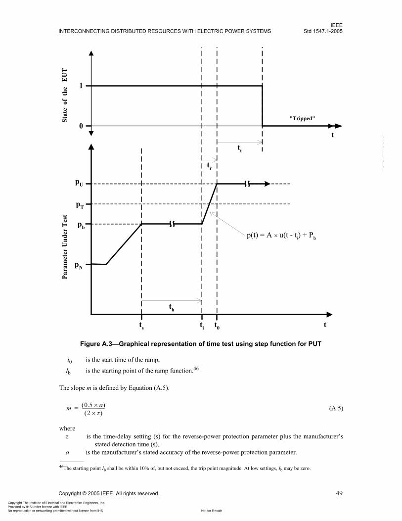
IEEEINTERCONNECTING DISTRIBUTED RESOURCES WITH ELECTRIC POWER SYSTEMS Std 1547.1-2005
Copyright © 2005 IEEE. All rights reserved. 49
t0 is the start time of the ramp,
Ib is the starting point of the ramp function.46
The slope m is defined by Equation (A.5).
(A.5)
wherez is the time-delay setting (s) for the reverse-power protection parameter plus the manufacturer’s
stated detection time (s),a is the manufacturer’s stated accuracy of the reverse-power protection parameter.
46The starting point Ib shall be within 10% of, but not exceed, the trip point magnitude. At low settings, Ib may be zero.
t
pN
th
pT
tr
pb
pU
ti
p(t) = A �u(t - ti) + Pb
t
1
0
ts
Stat
e o
f th
e E
UT
Para
met
er U
nder
Tes
t
"Tripped"
t0
tt
Figure A.3—Graphical representation of time test using step function for PUT
m 0.5 a�� �2 z�� �
---------------------=
Copyright The Institute of Electrical and Electronics Engineers, Inc. Provided by IHS under license with IEEE
Not for ResaleNo reproduction or networking permitted without license from IHS
--`,,```,,,,````-`-`,,`,,`,`,,`---
IEEEStd 1547.1-2005 IEEE STANDARD CONFORMANCE TEST PROCEDURES FOR EQUIPMENT
50 Copyright © 2005 IEEE. All rights reserved.
The current phase angle � defined as the phase difference between the voltage and current test signals shallbe varied according to Equation (A.6).
(A.6)
where� is the current phase angle,ts is the time when the phase-angle change occurs,t is time (s).
Figure A.4 is a graphical representation of a reverse-power magnitude test using the current magnitude rampfunction coupled with a current phase-angle step function. In the figure, i represents the current magnitude,� represents the phase angle of the current test signal, t represents time, IN is the nominal current condition,IT is the trip magnitude,47 t0 is the start time of the ramp, and ts is the instant when the phase transitionoccurs and the hold time48 th for the test signal starts at starting point Ib.
When the ramp function conflicts with a design characteristic or settings of the EUT, an alternative methodthat is agreeable to the manufacturer and the testing agency may be used.
A.4 Reverse-power time test (step function)
The test signal described in this subclause is used to characterize the accuracy of the time-delay setting forreverse-power protection parameter.
Vary the current test signals (i.e., magnitude and phase angle) according to the test function defined in thissubclause. Therefore, the voltage test signal shall be held at nominal values. The current test signal magni-tude i and phase angle � shall take the form described in Equation (A.7) and Equation (A.8).
(A.7)
wherei is the current test signal magnitude,t is time (s),A is a scaling factor,49
Ib is the starting point of the step function.50
(A.8)
where� is the current phase angle,ts is the time when the phase-angle change occurs,t is time (s).
47For the reverse-power magnitude test, the reverse-power trip magnitude will be a function of the magnitude of the current test signalbecause the voltage magnitude is at nominal and the phase difference between the voltage and current test signals, �, is 180�. Where theaccuracy of the measurement is affected by p.f., design of the test regimen shall accommodate various power factors.48See Footnote 40.49The scaling factor A shall be chosen so that Iu is at least 110% of IT. 50See Footnote 39.
� t� � 180– u t ts–� ��=
i A u t ti–� �� Ib+=
� t� � 180– u t ts–� ��=
Copyright The Institute of Electrical and Electronics Engineers, Inc. Provided by IHS under license with IEEE
Not for ResaleNo reproduction or networking permitted without license from IHS
--`,,```,,,,````-`-`,,`,,`,`,,`---
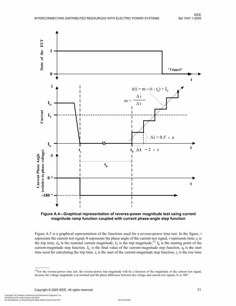
IEEEINTERCONNECTING DISTRIBUTED RESOURCES WITH ELECTRIC POWER SYSTEMS Std 1547.1-2005
Copyright © 2005 IEEE. All rights reserved. 51
Figure A.5 is a graphical representation of the functions used for a reverse-power time test. In the figure, irepresents the current test signal, � represents the phase angle of the current test signal, t represents time, tt isthe trip time, IN is the nominal current magnitude, IT is the trip magnitude,51 Ib is the starting point of thecurrent-magnitude step function, IU is the final value of the current-magnitude step function, t0 is the starttime used for calculating the trip time, ti is the start of the current-magnitude step function, tr is the rise time
51For the reverse-power time test, the reverse-power trip magnitude will be a function of the magnitude of the current test signal,because the voltage magnitude is at nominal and the phase difference between the voltage and current test signals, �, is 180�.
i(t) = m �(t - t0) + Ib
th
t0t
i
IN
IT
t = 2 � z
m = t i
= 0.5 � a i
t0 °
-180 °
ts
Ib
�
t
1
0
Stat
e o
f th
e E
UT
Cur
rent
Cur
rent
Pha
se A
ngle
(rel
ativ
e to
pha
se v
olta
ge)
"Tripped"
Figure A.4—Graphical representation of reverse-power magnitude test using current magnitude ramp function coupled with current phase-angle step function
Copyright The Institute of Electrical and Electronics Engineers, Inc. Provided by IHS under license with IEEE
Not for ResaleNo reproduction or networking permitted without license from IHS
--`,,```,,,,````-`-`,,`,,`,`,,`---

IEEEStd 1547.1-2005 IEEE STANDARD CONFORMANCE TEST PROCEDURES FOR EQUIPMENT
52 Copyright © 2005 IEEE. All rights reserved.
of the test signal from (t0 – ti),52 ts is the instant when the phase transition occurs and the hold time53 th forthe test signal starts at Ib.
When the step functions conflict with a design characteristic or settings of the EUT, an alternative methodthat is agreeable to the manufacturer and the testing agency may be used.
52The rise time tr shall be less than the larger of 1 cycle or 1% of the time-delay setting of the PUT.53See Footnote 40.
th
t
i
IN
IT
t0°
-180°
trIU
ti�ts
Ib
t
1
0
Stat
e o
f th
e E
UT
Cur
rent
Cur
rent
Pha
se A
ngle
(rel
ativ
e to
pha
se v
olta
ge)
"Tripped"
t0
tt
i(t) = A �u(t - ti) + Ib
Figure A.5—Graphical representation of reverse-power time test using current magnitude step function coupled with current phase-angle step function
Copyright The Institute of Electrical and Electronics Engineers, Inc. Provided by IHS under license with IEEE
Not for ResaleNo reproduction or networking permitted without license from IHS
--`,,```,,,,````-`-`,,`,,`,`,,`---

IEEEINTERCONNECTING DISTRIBUTED RESOURCES WITH ELECTRIC POWER SYSTEMS Std 1547.1-2005
Copyright © 2005 IEEE. All rights reserved. 53
Annex B
(informative)
Bibliography
The specifications refer to provisions that do not constitute provisions of this standard. They are listed toprovide additional useful information. At the time of publication, the editions indicated were valid. Allstandards and specifications are subject to revision, and parties to agreements based on this standard areencouraged to investigate the possibility of applying the most recent editions of the references listed below.
[B1] IEC TR3 61000-3-7, Electromagnetic Compatibility (EMC)—Part 3: Limits—Section 7: Assessmentof Emission Limits for Fluctuating Loads in MV and HV Power Systems—Basic EMC Publication.54
[B2] IEC 61000-4-15, Electromagnetic Compatibility (EMC)—Part 4: Testing and Measurement Tech-niques—Section 15: Flickermeter—Functional and Design Specifications.
[B3] IEC 61400-21, Wind Turbine Generator Systems—Part 21: Measurement and Assessment of PowerQuality Characteristics of Grid Connected Wind Turbines.
[B4] IEC 62116, Testing Procedure of Islanding Prevention Measures for Utility Interactive PhotovoltaicInverters.
[B5] IEEE 100, The Authoritative Dictionary of IEEE Standards Terms, Seventh Edition, New York, Insti-tute of Electrical and Electronics Engineers, Inc.55
[B6] IEEE P1547.2™, Draft Application Guide for IEEE Std 1547, Interconnecting Distributed Resourceswith Electric Power Systems.56
[B7] IEEE P1547.3™, Draft Guide for Monitoring, Information Exchange, and Control of DistributedResources Interconnected with Electric Power Systems.
[B8] IEEE P1547.4™, Draft Guide for Design, Operation, and Integration of Distributed Resource IslandSystems with Electric Power Systems.
[B9] IEEE P1547.5™, Draft Technical Guidelines for Interconnection of Electric Power Sources GreaterThan 10 MVA to the Power Transmission Grid.
[B10] IEEE P1547.6™, Draft Recommended Practice for Interconnecting Distributed Resources with Elec-tric Power Systems Distribution Secondary Networks.
[B11] IEEE Std C37.108™, IEEE Guide for the Protection of Network Transformers.
[B12] IEEE Std C57.12.44™, IEEE Standard Requirements for Secondary Network Protectors.
[B13] IEEE Std 120™, IEEE Master Test Guide for Electrical Measurements in Power Circuits.
54IEC publications are available from the Sales Department of the International Electrotechnical Commission, Case Postale 131, 3, ruede Varembé, CH-1211, Genève 20, Switzerland/Suisse (http://www.iec.ch/). IEC publications are also available in the United Statesfrom the Sales Department, American National Standards Institute, 11 West 42nd Street, 13th Floor, New York, NY 10036, USA.55IEEE publications are available from the Institute of Electrical and Electronics Engineers, 445 Hoes Lane, P.O. Box 1331, Piscat-away, NJ 08855-1331, USA (http://standards.ieee.org/).56The IEEE standards or products referred to in this clause are trademarks of the Institute of Electrical and Electronics Engineers, Inc.
Copyright The Institute of Electrical and Electronics Engineers, Inc. Provided by IHS under license with IEEE
Not for ResaleNo reproduction or networking permitted without license from IHS
--`,,```,,,,````-`-`,,`,,`,`,,`---

IEEEStd 1547.1-2005 IEEE STANDARD CONFORMANCE TEST PROCEDURES FOR EQUIPMENT
54 Copyright © 2005 IEEE. All rights reserved.
[B14] IEEE Std 519™, IEEE Recommended Practices and Requirements for Harmonic Control in ElectricalPower Systems.
[B15] IEEE Std 929™, IEEE Recommended Practice for Utility Interface of Photovoltaic (PV) Systems.
[B16] IEEE Std 1001™, IEEE Guide for Interfacing Dispersed Storage and Generation Facilities with Elec-tric Utility Systems.
[B17] IEEE Std 1453™, IEEE Recommended Practice for Measurement and Limits of Voltage Fluctuationsand Associated Light Flicker on AC Power Systems.
[B18] UL 1741, Static Inverters and Change Controllers for Use in Photovoltaic Power Systems.57
57UL standards are available from Global Engineering Documents, 15 Inverness Way East, Englewood, Colorado 80112, USA(http://global.ihs.com/).
Copyright The Institute of Electrical and Electronics Engineers, Inc. Provided by IHS under license with IEEE
Not for ResaleNo reproduction or networking permitted without license from IHS
--`,,```,,,,````-`-`,,`,,`,`,,`---


![[] IEEE 1120-2004 - IEEE Guide for the Planning, D(Book Fi org)](https://static.fdokumen.com/doc/165x107/63150fb6511772fe45103298/-ieee-1120-2004-ieee-guide-for-the-planning-dbook-fi-org.jpg)