92nd Clyde Littlefield Texas Relays Univ.of Texas-Mike A ...
Upload
khangminh22Category
view
4download
0
MIKE FLOOD
1D-2D Modelling
User Manual
MIKE 2017

2

PLEASE NOTE
COPYRIGHT This document refers to proprietary computer software which is pro-tected by copyright. All rights are reserved. Copying or other repro-duction of this manual or the related programs is prohibited without prior written consent of DHI. For details please refer to your 'DHI Software Licence Agreement'.
LIMITED LIABILITY The liability of DHI is limited as specified in Section III of your 'DHI Software Licence Agreement':
'IN NO EVENT SHALL DHI OR ITS REPRESENTATIVES (AGENTS AND SUPPLIERS) BE LIABLE FOR ANY DAMAGES WHATSOEVER INCLUDING, WITHOUT LIMITATION, SPECIAL, INDIRECT, INCIDENTAL OR CONSEQUENTIAL DAMAGES OR DAMAGES FOR LOSS OF BUSINESS PROFITS OR SAVINGS, BUSINESS INTERRUPTION, LOSS OF BUSINESS INFORMA-TION OR OTHER PECUNIARY LOSS ARISING OUT OF THE USE OF OR THE INABILITY TO USE THIS DHI SOFTWARE PRODUCT, EVEN IF DHI HAS BEEN ADVISED OF THE POSSI-BILITY OF SUCH DAMAGES. THIS LIMITATION SHALL APPLY TO CLAIMS OF PERSONAL INJURY TO THE EXTENT PERMIT-TED BY LAW. SOME COUNTRIES OR STATES DO NOT ALLOW THE EXCLUSION OR LIMITATION OF LIABILITY FOR CONSE-QUENTIAL, SPECIAL, INDIRECT, INCIDENTAL DAMAGES AND, ACCORDINGLY, SOME PORTIONS OF THESE LIMITATIONS MAY NOT APPLY TO YOU. BY YOUR OPENING OF THIS SEALED PACKAGE OR INSTALLING OR USING THE SOFT-WARE, YOU HAVE ACCEPTED THAT THE ABOVE LIMITATIONS OR THE MAXIMUM LEGALLY APPLICABLE SUBSET OF THESE LIMITATIONS APPLY TO YOUR PURCHASE OF THIS SOFT-WARE.'
3

4 MIKE FLOOD - © DHI

CONTENTS
1 Introduction . . . . . . . . . . . . . . . . . . . . . . . . . . . . . . . . . . . . . . 111.1 General Approach to Modelling with MIKE FLOOD . . . . . . . . . . . . . . . 121.2 How to Use this Manual . . . . . . . . . . . . . . . . . . . . . . . . . . . . . 13
2 General Description of Model Linkages . . . . . . . . . . . . . . . . . . . . . 152.1 The Standard Link . . . . . . . . . . . . . . . . . . . . . . . . . . . . . . . . 152.2 The Lateral Link . . . . . . . . . . . . . . . . . . . . . . . . . . . . . . . . . 162.3 The Structure Link . . . . . . . . . . . . . . . . . . . . . . . . . . . . . . . . 172.4 The Urban Link . . . . . . . . . . . . . . . . . . . . . . . . . . . . . . . . . . 182.5 The Zero Flow Link (X and Y) . . . . . . . . . . . . . . . . . . . . . . . . . . 192.6 The River - Urban link . . . . . . . . . . . . . . . . . . . . . . . . . . . . . . 202.7 The Side Structure Link . . . . . . . . . . . . . . . . . . . . . . . . . . . . . 21
3 The MIKE FLOOD Editor . . . . . . . . . . . . . . . . . . . . . . . . . . . . . . 233.1 Link Parameters - Global Link Settings . . . . . . . . . . . . . . . . . . . . . 24
3.1.1 Default values, MIKE 21/MIKE 11 links . . . . . . . . . . . . . . . . . 253.1.2 Default values, MIKE 21/MIKE Urban links . . . . . . . . . . . . . . . 263.1.3 Default values, MIKE 11/MIKE URBAN links . . . . . . . . . . . . . . 273.1.4 Change existing values, MIKE 21/MIKE 11 links . . . . . . . . . . . . 283.1.5 Change existing values, MIKE 21/MIKE Urban links . . . . . . . . . . 293.1.6 Change existing values, MIKE 11/MIKE URBAN links . . . . . . . . . 303.1.7 Change existing values, Select Links to Change . . . . . . . . . . . . 31
3.2 The Linkage Files Page . . . . . . . . . . . . . . . . . . . . . . . . . . . . . 323.2.1 2D Surface Model . . . . . . . . . . . . . . . . . . . . . . . . . . . . 323.2.2 River Model . . . . . . . . . . . . . . . . . . . . . . . . . . . . . . . 333.2.3 Urban Model . . . . . . . . . . . . . . . . . . . . . . . . . . . . . . 33
3.3 The Link Definitions page . . . . . . . . . . . . . . . . . . . . . . . . . . . . 343.3.1 Link types; feature overview . . . . . . . . . . . . . . . . . . . . . . 353.3.2 Table of defined model links . . . . . . . . . . . . . . . . . . . . . . 37
3.4 The Graphical Layout . . . . . . . . . . . . . . . . . . . . . . . . . . . . . . 413.4.1 Select and activate linkages graphically . . . . . . . . . . . . . . . . 443.4.2 Editing linkage lines graphically . . . . . . . . . . . . . . . . . . . . 443.4.3 Information on the individual cells . . . . . . . . . . . . . . . . . . . 463.4.4 Add/Remove layers... . . . . . . . . . . . . . . . . . . . . . . . . . . 463.4.5 Layer properties... . . . . . . . . . . . . . . . . . . . . . . . . . . . 483.4.6 Add/Remove images... . . . . . . . . . . . . . . . . . . . . . . . . . 543.4.7 Link river branches to MIKE 21 . . . . . . . . . . . . . . . . . . . . . 553.4.8 Block out river cells... . . . . . . . . . . . . . . . . . . . . . . . . . . 583.4.9 Link urban node to MIKE 21... . . . . . . . . . . . . . . . . . . . . . 63
5

3.4.10 Link river branch to MIKE URBAN... . . . . . . . . . . . . . . . . . . 633.4.11 Export links to selection File... . . . . . . . . . . . . . . . . . . . . . 64
3.5 Details on Standard / Structure Links Options, . . . . . . . . . . . . . . . . . 663.5.1 Mom fact . . . . . . . . . . . . . . . . . . . . . . . . . . . . . . . . 673.5.2 Ext fact . . . . . . . . . . . . . . . . . . . . . . . . . . . . . . . . . 673.5.3 Add / replace momentum terms . . . . . . . . . . . . . . . . . . . . 683.5.4 Depth adjustment . . . . . . . . . . . . . . . . . . . . . . . . . . . 683.5.5 Activation depth (minimum and maximum) . . . . . . . . . . . . . . 693.5.6 Exponential smoothing factor . . . . . . . . . . . . . . . . . . . . . 69
3.6 Details on Lateral Links Options . . . . . . . . . . . . . . . . . . . . . . . . . 713.6.1 Side of river . . . . . . . . . . . . . . . . . . . . . . . . . . . . . . 723.6.2 Method . . . . . . . . . . . . . . . . . . . . . . . . . . . . . . . . . 723.6.3 Structure type . . . . . . . . . . . . . . . . . . . . . . . . . . . . . 723.6.4 Source . . . . . . . . . . . . . . . . . . . . . . . . . . . . . . . . . 733.6.5 Depth tolerance . . . . . . . . . . . . . . . . . . . . . . . . . . . . 743.6.6 Structure coefficients . . . . . . . . . . . . . . . . . . . . . . . . . . 743.6.7 External files for lateral links . . . . . . . . . . . . . . . . . . . . . . 753.6.8 Additional lateral Linkage feature; Linkage Level analysis . . . . . . . 763.6.9 Lateral links in rectangular grids and flexible mesh . . . . . . . . . . 78
3.7 Details on Urban Link Options . . . . . . . . . . . . . . . . . . . . . . . . . . 793.7.1 Type . . . . . . . . . . . . . . . . . . . . . . . . . . . . . . . . . . 793.7.2 Inlet method . . . . . . . . . . . . . . . . . . . . . . . . . . . . . . 803.7.3 Max flow . . . . . . . . . . . . . . . . . . . . . . . . . . . . . . . . 813.7.4 Inlet area . . . . . . . . . . . . . . . . . . . . . . . . . . . . . . . . 813.7.5 Crest width . . . . . . . . . . . . . . . . . . . . . . . . . . . . . . . 813.7.6 Discharge coefficient . . . . . . . . . . . . . . . . . . . . . . . . . . 813.7.7 Scaling factor . . . . . . . . . . . . . . . . . . . . . . . . . . . . . . 823.7.8 Exponent factor . . . . . . . . . . . . . . . . . . . . . . . . . . . . 823.7.9 Qdh factor . . . . . . . . . . . . . . . . . . . . . . . . . . . . . . . 823.7.10 Freeboard . . . . . . . . . . . . . . . . . . . . . . . . . . . . . . . 823.7.11 Capacity curve DQ Relation . . . . . . . . . . . . . . . . . . . . . . 82
3.8 Details on River - Urban Link Options . . . . . . . . . . . . . . . . . . . . . . 823.9 Details on Side Structure Link Options . . . . . . . . . . . . . . . . . . . . . 843.10 AD Components . . . . . . . . . . . . . . . . . . . . . . . . . . . . . . . . . 85
4 Simulation Results . . . . . . . . . . . . . . . . . . . . . . . . . . . . . . . . . 874.1 Defining Result Files for a MIKE Flood Simulation . . . . . . . . . . . . . . . 874.2 Seamless Integrated 1D and 2D River Flooding Results . . . . . . . . . . . . 87
5 Running MIKE Flood- recommended Steps . . . . . . . . . . . . . . . . . . . 895.1 Define Model Layout . . . . . . . . . . . . . . . . . . . . . . . . . . . . . . . 895.2 Setup and Run 1D Models . . . . . . . . . . . . . . . . . . . . . . . . . . . . 895.3 Setup and Run MIKE 21 Model . . . . . . . . . . . . . . . . . . . . . . . . . 905.4 Setup MIKE FLOOD . . . . . . . . . . . . . . . . . . . . . . . . . . . . . . . 905.5 Run MIKE FLOOD Simulation . . . . . . . . . . . . . . . . . . . . . . . . . . 90
6 Pre- and Post-processing . . . . . . . . . . . . . . . . . . . . . . . . . . . . . 916.1 Volume Balance Summary from Simulations . . . . . . . . . . . . . . . . . . 92
6 MIKE FLOOD - © DHI

7 Tips and Troubleshooting . . . . . . . . . . . . . . . . . . . . . . . . . . . . . 957.1 General Considerations . . . . . . . . . . . . . . . . . . . . . . . . . . . . . 95
7.1.1 River modelling with MIKE HYDRO River or MIKE 11 . . . . . . . . . 957.1.2 MIKE 21 rectangular grid . . . . . . . . . . . . . . . . . . . . . . . . 967.1.3 MIKE 21 flexible mesh . . . . . . . . . . . . . . . . . . . . . . . . . 977.1.4 MIKE URBAN . . . . . . . . . . . . . . . . . . . . . . . . . . . . . . 98
7.2 Stability Issues . . . . . . . . . . . . . . . . . . . . . . . . . . . . . . . . . . 987.2.1 General MIKE FLOOD issues . . . . . . . . . . . . . . . . . . . . . 987.2.2 MIKE 11 specific issues . . . . . . . . . . . . . . . . . . . . . . . . 99
7.3 Standard Links . . . . . . . . . . . . . . . . . . . . . . . . . . . . . . . . . . 997.4 Lateral Links . . . . . . . . . . . . . . . . . . . . . . . . . . . . . . . . . . 1007.5 Structure Links . . . . . . . . . . . . . . . . . . . . . . . . . . . . . . . . . 1027.6 Zero Flow Links . . . . . . . . . . . . . . . . . . . . . . . . . . . . . . . . 1037.7 Urban links . . . . . . . . . . . . . . . . . . . . . . . . . . . . . . . . . . . 1047.8 River Urban links . . . . . . . . . . . . . . . . . . . . . . . . . . . . . . . . 104
8 Scientific Background . . . . . . . . . . . . . . . . . . . . . . . . . . . . . . . 1058.1 Hydrodynamics - Standard Links . . . . . . . . . . . . . . . . . . . . . . . . 105
8.1.1 Rectangular grid . . . . . . . . . . . . . . . . . . . . . . . . . . . 1058.1.2 Flexible mesh . . . . . . . . . . . . . . . . . . . . . . . . . . . . . 106
8.2 Hydrodynamics - Lateral Links . . . . . . . . . . . . . . . . . . . . . . . . . 1068.2.1 Rectangular Grid . . . . . . . . . . . . . . . . . . . . . . . . . . . 1068.2.2 Automated cell selection . . . . . . . . . . . . . . . . . . . . . . . 1098.2.3 Definition of lateral linkage lines . . . . . . . . . . . . . . . . . . . 110
8.3 Hydrodynamics - Structure Links . . . . . . . . . . . . . . . . . . . . . . . . 1118.3.1 Hydrodynamics - Exponential smoothing factor . . . . . . . . . . . 113
8.4 Hydrodynamics - Zero Flow Links . . . . . . . . . . . . . . . . . . . . . . . 1138.5 Hydrodynamics - Urban links . . . . . . . . . . . . . . . . . . . . . . . . . . 1148.6 Urban River Links . . . . . . . . . . . . . . . . . . . . . . . . . . . . . . . 1158.7 Advection-Dispersion . . . . . . . . . . . . . . . . . . . . . . . . . . . . . . 1158.8 Flow Distribution by Depth . . . . . . . . . . . . . . . . . . . . . . . . . . . 1168.9 Inclusion of Friction Term in Weir Formulae 1 and 2 (Honma) . . . . . . . . . 117
9 Examples . . . . . . . . . . . . . . . . . . . . . . . . . . . . . . . . . . . . . . 1219.1 Standing Wave . . . . . . . . . . . . . . . . . . . . . . . . . . . . . . . . . 1219.2 Lateral Link 1 . . . . . . . . . . . . . . . . . . . . . . . . . . . . . . . . . . 1239.3 Lateral Link 2 . . . . . . . . . . . . . . . . . . . . . . . . . . . . . . . . . . 1299.4 Flow Direction . . . . . . . . . . . . . . . . . . . . . . . . . . . . . . . . . 1329.5 Flood plain Flow . . . . . . . . . . . . . . . . . . . . . . . . . . . . . . . . 1369.6 Floodplain Demonstration . . . . . . . . . . . . . . . . . . . . . . . . . . . 1389.7 Urban examples . . . . . . . . . . . . . . . . . . . . . . . . . . . . . . . . 143
9.7.1 Urban . . . . . . . . . . . . . . . . . . . . . . . . . . . . . . . . . 1439.7.2 Waterville . . . . . . . . . . . . . . . . . . . . . . . . . . . . . . . 143
9.8 MIKE FLOOD 3way . . . . . . . . . . . . . . . . . . . . . . . . . . . . . . 1449.8.1 River links between MIKE 11 and MIKE 21 . . . . . . . . . . . . . . 1469.8.2 Urban links between MIKE URBAN and MIKE 21 . . . . . . . . . . 1479.8.3 River/Urban links between MIKE URBAN and MIKE 11 . . . . . . . 148
7

8 MIKE FLOOD - © DHI

MIKE FLOOD
User Guide
9

10 MIKE FLOOD - © DHI

1 Introduction
MIKE FLOOD is a product that integrates the one-dimensional models MIKE URBAN (MOUSE), MIKE HYDRO River, MIKE 11 and the two-dimensional model MIKE 21 into a single, dynamically coupled modelling system.
Using a coupled approach enables the best features of both the one -dimen-sional and the two dimensional models to be utilised, whilst at the same time avoiding many of the limitations of resolution and accuracy encountered when using MIKE HYDRO River, MIKE 11, MIKE URBAN (MOUSE engine) or MIKE 21 separately.
Special features of MIKE FLOOD include:
Lateral links, enabling simulation of over bank flow from river channel to flood plain
Comprehensive hydraulic structures package
Implicit structure links
Manhole links whereby the interaction of the sewer/storm water system may interact with the overland flow
River/urban links securing direct linking between the collection system and the river network
GIS integration
Links possible along any alignment in MIKE 21 (not just horizontally or vertically)
A graphical user interface, allowing for easy data input and output as well as data preparation and analysis.
A thorough on-line help system, user guide and technical reference doc-umentation
Support and continuing commitment from DHI
There are many advantages to using MIKE FLOOD and many model applica-tions can be improved through its use, including:
Flood plain applications
Storm surge studies
Urban drainage
Dam break
Hydraulic design of structures
Broad scale estuarine applications
11

Introduction
1.1 General Approach to Modelling with MIKE FLOOD
Consider the modelling systems that are integrated: MIKE HYDRO River, MIKE 11, MIKE URBAN(MOUSE) and MIKE 21. By combining - or linking - the systems the modeller can choose the best features of each and make the best model with these features.
For instance, consider the following abilities and limitations of MIKE HYDRO River and MIKE 11:
Has comprehensive and proven structure routines
Can model very long or complicated river systems with little computa-tional effort
Can model one dimensional channel flow accurately
Can be easily linked to rainfall and runoff programs
Can simulate high velocity/super critical flow conditions
Is one dimensional, so two dimensional effects such as cross-channel momentum is not possible
Overland flow is difficult to model if flow paths are uncertain
Requires more conceptualisation of flow conditions and more approxi-mations
Cannot easily simulate a coastal situation
Consider then MIKE URBAN(MOUSE):
Has sophisticated descriptions for pipe flow and structures
Can model highly complex pipe networks
Can be easily linked to rainfall and runoff programs
May be used to model open sections
Is one dimensional, so a true two dimensional description of the overland flow is not possible
Difficult to describe the complex interaction between overland flow and pipe flow
Finally consider MIKE 21:
Two dimensional means more accuracy and better resolution
Overland flow can be simulated without apriori knowledge of flow paths
Flooding and drying may be efficiently handled using robust algorithms
Can simulate high velocity / supercritical flow conditions
Can simulate a coastal situation
Requires more computational effort
12 MIKE FLOOD - © DHI
How to Use this Manual
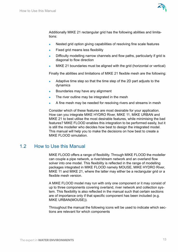
Additionally MIKE 21 rectangular grid has the following abilities and limita-tions:
Nested grid option giving capabilities of resolving fine scale features
Fixed grid means less flexibility
Difficulty modelling narrow channels and flow paths, particularly if grid is diagonal to flow direction
MIKE 21 boundaries must be aligned with the grid (horizontal or vertical)
Finally the abilities and limitations of MIKE 21 flexible mesh are the following:
Adaptive time step so that the time step of the 2D part adjusts to the dynamics
Boundaries may have any alignment
The river outline may be integrated in the mesh
A fine mesh may be needed for resolving rivers and streams in mesh
Consider which of these features are most desirable for your application. How can you integrate MIKE HYDRO River, MIKE 11, MIKE URBAN and MIKE 21 to best utilise the most desirable features, while minimising the bad features? MIKE FLOOD enables this integration to be performed easily, but it is still the modeller who decides how best to design the integrated model. This manual will help you to make the decisions on how best to create a MIKE FLOOD simulation.
1.2 How to Use this Manual
MIKE FLOOD offers a range of flexibility. Through MIKE FLOOD the modeller can couple a pipe network, a river/stream network and an overland flow solver into one model. This flexibility is reflected in the range of modelling packages integrated in MIKE FLOOD namely MOUSE, MIKE HYDRO River, MIKE 11 and MIKE 21, where the latter may either be a rectangular grid or a flexible mesh version.
A MIKE FLOOD model may run with only one component or it may consist of up to three components covering overland, river network and collection sys-tem. This flexibility is also reflected in the manual such that certain sections are of importance only if that specific component has been included (e.g. MIKE URBAN(MOUSE)).
Throughout the manual the following icons will be used to indicate which sec-tions are relevant for which components
13

Introduction
Icon for MIKE 21 rectangular grid model component
Icon for MIKE 21 flexible mesh model component
Icon for MIKE HYDRO River / MIKE 11 component
Icon for MIKE URBAN(MOUSE) component
Links may be defined between any of the three model components MIKE 21, MIKE HYDRO River, MIKE 11 and MIKE URBAN(MOUSE). Further MIKE 21 may either be a rectangular grid version or a flexible mesh version.
NOTE: All the individual components required for the coupled modelling need to be licensed.
NOTE: As a rule of thump, comments made for MIKE 11 in this manual also apply to MIKE HYDRO River.
14 MIKE FLOOD - © DHI

The Standard Link
2 General Description of Model Linkages
Coupling of the different models are made through different linkage options. Seven different types of links are presently available in MIKE Flood:
1. Standard Link
2. Lateral Link
3. Structure Link
4. Side Structures Link
5. Zero Flow links (XFlow=0 and YFlow=0)
6. Urban Link
7. River-Urban Link
Link types 1 to 5 above concern the coupling of MIKE 11 and MIKE 21, Link type 6 is designed for linking MIKE URBAN with one or more cells/elements in MIKE 21 and finally, Link type 7 is reserved for linking the river network (MIKE 11) with the collection system (MIKE URBAN).
A description of each of these link types follows below.
2.1 The Standard Link
This is the standard linkage in MIKE FLOOD, where one or more MIKE 21 cells/elements are linked to the end of a MIKE 11 river branch.
This type of link is useful for connecting a detailed MIKE 21 grid/mesh into a broader MIKE 11 network, or to connect an internal structure (with an extent of more than a grid cell) or feature inside a MIKE 21 grid/mesh.
Potential applications are as shown below:
15
General Description of Model Linkages
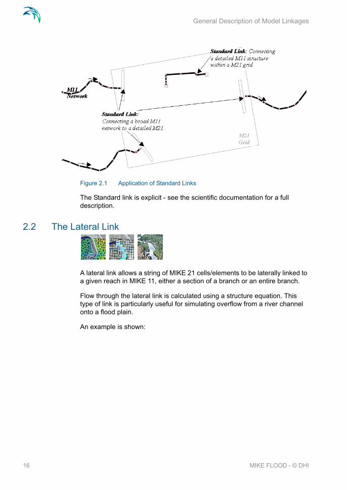
Figure 2.1 Application of Standard Links
The Standard link is explicit - see the scientific documentation for a full description.
2.2 The Lateral Link
A lateral link allows a string of MIKE 21 cells/elements to be laterally linked to a given reach in MIKE 11, either a section of a branch or an entire branch.
Flow through the lateral link is calculated using a structure equation. This type of link is particularly useful for simulating overflow from a river channel onto a flood plain.
An example is shown:
16 MIKE FLOOD - © DHI
The Structure Link
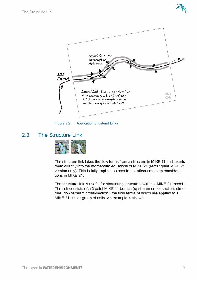
Figure 2.2 Application of Lateral Links
2.3 The Structure Link
The structure link takes the flow terms from a structure in MIKE 11 and inserts them directly into the momentum equations of MIKE 21 (rectangular MIKE 21 version only). This is fully implicit, so should not affect time step considera-tions in MIKE 21.
The structure link is useful for simulating structures within a MIKE 21 model. The link consists of a 3 point MIKE 11 branch (upstream cross-section, struc-ture, downstream cross-section), the flow terms of which are applied to a MIKE 21 cell or group of cells. An example is shown:
17

General Description of Model Linkages
Figure 2.3 Application of Structure Links. Only to be used for a rectangular grid
2.4 The Urban Link
The urban link is designed to describe the interaction of water when a man-hole is overtopped or when overland flow enters a sewer/storm water net-work.
Figure 2.4 Flooding from MIKE 21 into a non-surcharged sewer system
18 MIKE FLOOD - © DHI

The Zero Flow Link (X and Y)
The urban link may also be used for linking a sewer outlet with the overland topography. This may be used to describe the dynamic interaction between a sewer system and a collection basin described using the topography as opposed to describing the basin using an area elevation curve.
Finally the link is also applicable to situations where the sewer system is dis-charging into the surrounding area through a pump or over a weir. In these cases the pump or the weir must be defined as having no downstream node.
Figure 2.5 Flooding from a surcharged sewer system into MIKE 21
The link is designed such that one or more cells/elements in MIKE 21 may be linked to a manhole, basin, outlet, pump or weir in MIKE URBAN(MOUSE).
2.5 The Zero Flow Link (X and Y)
A MIKE 21 cell specified as a zero flow link in the x direction will have zero flow passing across the right side of the cell. Similarly, a zero flow link in the y direction will have zero flow passing across the top of the cell.
The zero flow links were developed to complement the lateral flow links. To ensure that flood plain flow in MIKE 21 does not travel directly across a river to the opposite side of the flood plain without passing through MIKE 11, zero flow links are inserted to block MIKE 21 flows. An alternative to using the zero flow links is to apply land cells which, depending upon grid resolution, may not be appropriate.
Another useful application of zero flow links is to represent narrow blockages on a flood plain, such as roads and levees. Rather than using a string of land cells, a string of zero flow cells can be used.
19

General Description of Model Linkages
Note this link is only available when linking MIKE 21 rectangular grid to MIKE 11.
2.6 The River - Urban link
The river urban link has been designed for modelling the dynamic interaction of the river network and the collection system. Areas of application are
Collection system discharging to a river through an outlet
Pumps discharging to a canal
A collection system spilling into a stream over a weir
The river - urban link has been designed so that it may be used with a full three component model but is also applicable when the model only consists of MIKE URBAN(MOUSE) and MIKE 11.
Figure 2.6 illustrates the situation with a sewer outlet discharging into a river. For this case the user needs to supply the river link location through a branch name and a chainage. The link will be placed at the nearest river cross sec-tion in the river. For the sewer the user must specify the outlet ID and ensure that a standard water level boundary condition is applied (no Q/H relation allowed).
Figure 2.6 A sewer outlet discharging into a river. The water level in the river will have an impact on the flow through the outlet. Note that an adverse head difference at the outlet will drive flow into the sewer system
Figure 2.7 illustrates the situation where a sewer system is connected to a river through a weir in the sewer system. Note that the weir must be specified as having no “to node” i.e. out of the sewer system. In this case the user sup-plies the river location and the ID of the weir. The situation with a pump is
20 MIKE FLOOD - © DHI

The Side Structure Link
similar. The user in this case supplies the ID of the pump to be linked. Both the pump and the weir links are uni-directional i.e. flow is only allowed from the sewer system to the river and not vice versa.
Figure 2.7 A cross sectional illustration of a sewer discharging into a river through a weir. Note that the flow is uni-directional. Thus the water can only travel from the sewer system to the river and not vice versa
2.7 The Side Structure Link
The Side Structure Link is designed to model interaction between the river model and the overland flow model through Side Structures as defined in MIKE 11.
Side structures can be defined in MIKE 11 for almost all structure types avail-able and then are typically applied in MIKE 11 to define local lateral abstrac-tion (or source) of water from the main river course in applications where either fixed hydraulic structures are present to convey water from the main river course to a neighbour area or channel-system or where e.g. a local breach of embankment occurred during a historical event.
Typical applications of Side Structure link are:
Fixed hydraulic structure embedded locally in the river embankments such as drainage pipes (eventually with a directional valve control), local low-crested spill-structures etc.
Local Controllable structures such as pumps and gates for flood control and irrigation.
Embankment breaches where breaches can be described using a dam-break structure using either a time controlled or soil erosion breach defi-nition.
The principle in the Side Structure Linkage is illustrated in Figure 2.8.
21

General Description of Model Linkages
Figure 2.8 Illustration of Side Structure linkage with water spilling from the river to the flood plains through side structures located at specific locations within the River model
The Side Structure Link is explicit and implemented in the computational engine equivalent to the Standard Link option (for further details, see scien-tific documentation).
For details on the actual user-specification of Side Structures as well as the numerical approach for implementing Side Structures, please consult the MIKE 11 Documentation (Users guide and Reference Manual).
22 MIKE FLOOD - © DHI

The Side Structure Link
3 The MIKE FLOOD Editor
The MIKE FLOOD editor consists of a number of sub-pages with Graphical and Tabular editing possibilities combined with a navigational tree-view. The opening page of MIKE FLOOD editor is presented below.
Figure 3.1 MIKE FLOOD Editor; Opening Page
Any combination of links can be used in a MIKE FLOOD simulation. All the information relating to the MIKE FLOOD links is contained in one file: the cou-pling file (file extension.COUPLE).
The MIKE 11, MIKE 21 and MIKE URBAN simulation files do not contain any information relating specifically to the linkages between models, except for:
A dummy water level boundary condition must be applied at each stand-ard or implicit link point in MIKE 11.
The coupling file interface is arranged with a number of sub-menus which are easily accessed by clicking on any of the lines in the tree-view on the left side of the MIKE FLOOD Editor (see Figure 3.1).
The sub-pages available are:
Linkage files
23

The MIKE FLOOD Editor
Link Definitions
Standard / Structure Link Options
Lateral Link Options
Urban Link Options
River Urban Link Options
Side Structure Link Options
AD Components
Each of the sub-menus is described in Sections 3.2 to 3.10.
In addition to the above listed linkage definition sub-menus, an option for changing the default values for new links or changing parameter values for existing links of specific types can be found through the main menu bar of the editor. The Change Link Parameters option is described in the following sec-tion.
3.1 Link Parameters - Global Link Settings
The Main menu bar of the Couple editor contains the ‘Link Parameters’ option which contains three entries as presented in Figure 3.3:
‘Default Values’When using the automatic linkage tool within MIKE FLOOD a number of default values are assigned to the created links. Editing of link parame-ters can be made subsequently, but the ‘Default Values’ tool is an option for changing the link parameter values assigned per default.
‘Apply to Existing’The Apply to Existing tool makes it possible to change link parameters globally for one or multiple link types in one operation. In an established MIKE FLOOD setup it is often required to change the value of one or more link parameters globally. For a small setup with few links this is relatively simple, but for a setup with a large number of links this change becomes rather time consuming and the Apply to Existing tool is developed to ease the global editing of multiple links.
'Invert M11 negative branch sections'This switch allows the user to invert the direction (left to right side) of cross sections for branches defined with negative flow direction.
Figure 3.2 Link Parameters Main Menu bar option; ‘Default values’ tool
24 MIKE FLOOD - © DHI

Link Parameters - Global Link Settings
Figure 3.3 Link Parameters Main Menu bar option; ‘Apply to existing’ tool
Please note that changing default value settings are only effective within the specific Couple-file being active as these values are saved in the file. Open-ing - or creating - another couple file may therefore require the user to change default values again for values to take effect in this file.
Details of the tools available within the Link Parameter option is described in the following.
3.1.1 Default values, MIKE 21/MIKE 11 links
Changing default values for parameters in all types of MIKE 21 / MIKE 11 links can be made through this dialog.
Parameters are grouped depending on which link-type they relate to. The parameters ‘Exponential Smoothing’ and ‘Depth Adjustment’ on the bottom of the page are used in multiple link-types and hence presented separately (see Figure 3.4).
25

The MIKE FLOOD Editor
Figure 3.4 Dialog for changing Default Values for MIKE 11 / MIKE 21 Links
For details on the individual parameters, see the respective sections; ‘Details on Standard / Structure Links Options,’, ‘Details on Lateral Links Options’ and ‘Details on Side Structure Link Options’.
To change default values for the couple-file, adjust the required parameters and press OK. Press Cancel to close the Default Values dialog without changing parameters.
3.1.2 Default values, MIKE 21/MIKE Urban links
Default values for MIKE 21 / MIKE Urban links can be changed in this dialog (see Figure 3.5).
26 MIKE FLOOD - © DHI

Link Parameters - Global Link Settings
Figure 3.5 Dialog for changing Default Values for MIKE 21 / MIKE Urban Links
For details on the individual parameters, see the section; ‘Details on Urban Link Options’.
To change default values for the couple-file, adjust the required parameters and press OK. Press Cancel to close the Default Values dialog without changing parameters.
3.1.3 Default values, MIKE 11/MIKE URBAN links
The Default values for the River / Urban links can be made in this dialog (see Figure 3.6).
Further details on the link type variables can be found in the section; ‘Details on River - Urban Link Options’.
Figure 3.6 Dialog for changing Default Values for MIKE 11 / MIKE URBAN Links
To change default values for the couple-file, adjust the required parameters and press OK. Press Cancel to close the Default Values dialog without changing parameters.
27

The MIKE FLOOD Editor
3.1.4 Change existing values, MIKE 21/MIKE 11 links
Global changes to MIKE 21 / MIKE 11 link types can be made through this dialog, where the user decides which link-type is to be changed and which parameters should be included in the global change (see Figure 3.7).
Figure 3.7 Dialog for changing existing MIKE 11 / MIKE 21 link parameters
Use the list of radio buttons in the ‘Link Types’ group-box to select which link types that are to be included in the global change. If you select a specific link type, parameters will be changed for this particular type only. Alternatively, you can select “All” in order to change the parameters of multiple link types in the same operation.
Tick-boxes for parameters in the dialog are related to a specific link type and they become active depending on the selection in the ‘Link Type’ radio button group. Activate one or multiple tick-boxes to activate the specific edit field for the parameters, which should be globally adjusted, and change the parame-ter values as requested.
Press the ‘Apply’ button to change values of the activated link parameters.
28 MIKE FLOOD - © DHI

Link Parameters - Global Link Settings
Please note that the Apply operation cannot be reverted automatically. Press Cancel to close dialog without changing parameter values.
If it is required to change parameter values for only a subset of existing links this is also possible through this dialog. Activate the ‘Selected’ option in the ‘Apply To’ group box and the button becomes active. Press the button to open the ‘Select Links’ dialog (see Figure 3.10) and select the spe-cific Links which should be changed by selecting / crossing the tick-box in the Select column at the respective links. Further details in section 3.1.7.
For details on the individual parameters, see the respective sections; ‘Details on Standard / Structure Links Options,’, ‘Details on Lateral Links Options’ and ‘Details on Side Structure Link Options’.
3.1.5 Change existing values, MIKE 21/MIKE Urban links
Global changes to existing MIKE 21 / MIKE Urban links can be made through this dialog (presented in Figure 3.8).
Figure 3.8 Dialog for changing existing MIKE 21 / MIKE Urban link parameters
Activate one or multiple tick-boxes to activate the specific edit field for the parameters, which should be globally adjusted and change the parameter values as requested. Tick-boxes will become active depending on the Link Type selection in the ‘Apply to Links of Type’ combo-box as well as the method selection in the ‘Inlet Method’ combo-box.
29
The MIKE FLOOD Editor
If it is required to change parameter values for only a subset of existing links this is also possible through this dialog. Activate the ‘Selected’ option in the ‘Apply To’ group box and the button becomes active. Press the button to open the ‘Select Links’ dialog (see Figure 3.10) and select the spe-cific Links which should be changed by selecting / crossing the tick-box in the Select column at the respective links. Further details in section 3.1.7.
Press ‘Apply’ button to change values of the activated link parameters.
Please note that the Apply operation cannot be reverted automatically. Press ‘Cancel’ to close the dialog without changing any parameter values.
The last option on this dialog; ‘Extent of 2D coupling with manhole’ allows automatic addition of 2D cells or mesh elements in the MIKE 21 model for the couplings. Per default only one cell or element are defined at the location of the urban model element in a coupling, but multiple 2D elements in an Urban coupling are often required e.g. to secure improved model stability. ‘Width of search square’ defines the threshold extent of a square within which the addi-tional 2D elements are identified and included in the Urban couplings.
For details on all other individual parameters in this dialog, see the section; ‘Details on Urban Link Options’.
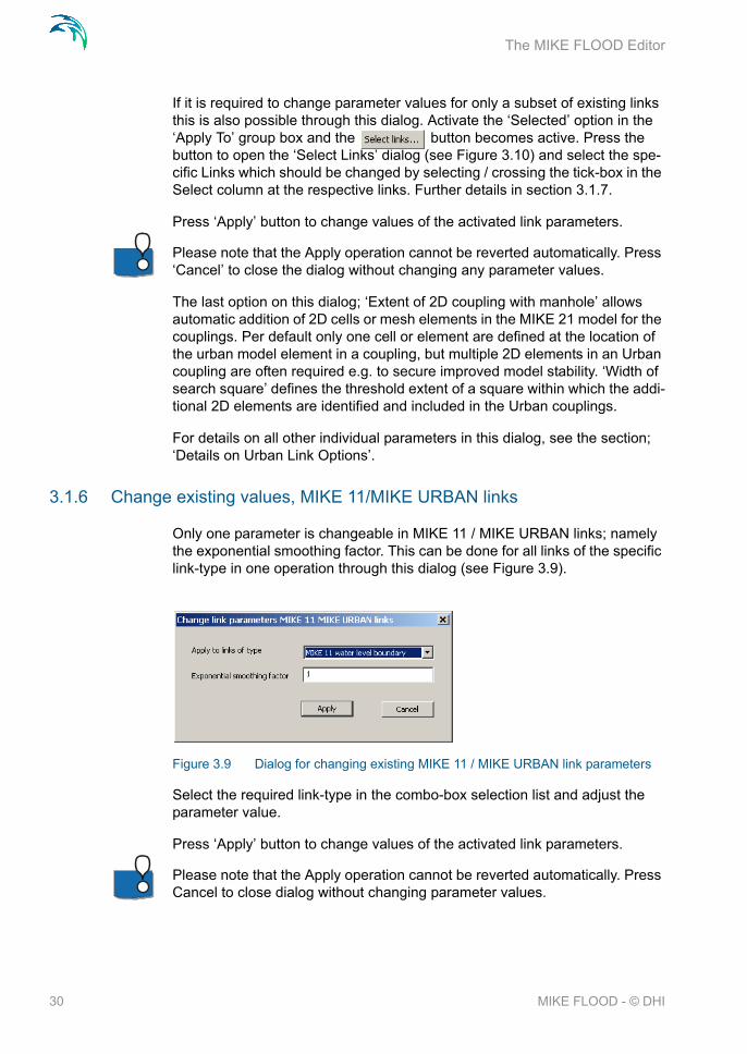
3.1.6 Change existing values, MIKE 11/MIKE URBAN links
Only one parameter is changeable in MIKE 11 / MIKE URBAN links; namely the exponential smoothing factor. This can be done for all links of the specific link-type in one operation through this dialog (see Figure 3.9).
Figure 3.9 Dialog for changing existing MIKE 11 / MIKE URBAN link parameters
Select the required link-type in the combo-box selection list and adjust the parameter value.
Press ‘Apply’ button to change values of the activated link parameters.
Please note that the Apply operation cannot be reverted automatically. Press Cancel to close dialog without changing parameter values.
30 MIKE FLOOD - © DHI

Link Parameters - Global Link Settings
Further details on the link type variables can be found in the section; ‘Details on River - Urban Link Options’.
3.1.7 Change existing values, Select Links to Change
Apply changes to existing links can be made as a global operation where all links in the setup are changed in one operation. However, it is desirable also to be able to change values for a sub-set of defined links to differentiate parameters of different links, and the selection of links to be changed in this process is made using the Select Links dialog (Figure 3.10).
Open the Select Links page from one of the Change Existing Parameter value pages by pressing the button in these pages. A list of all links of the specified link types in the model setup is presented in the table, and the specific links which shall be processed during the following change of link parameter values is simply selected by activating the respective tick-boxes in the ‘Select’ column.
Figure 3.10 Link Selection dialog for selection of specific links to be included in Global change of parameter values for existing links. Figure illustrates a number of MIKE 21 / MIKE 11 links where ‘All’ link types has been selected in the Change Parameter Value page
Press OK to activate the selection and return to the Change Existing Value page from which you entered the Select Links option. Click Cancel to return without activating any selections.
31

The MIKE FLOOD Editor
3.2 The Linkage Files Page
The Linkage Files definition page contains information about the respective 1D and 2D model setup files used for couplings in the MIKE FLOOD setup.
Figure 3.11 Linkage Files definition page of the MIKE FLOOD Editor
3.2.1 2D Surface Model
It is optional whether to include a MIKE 21 set up or not in MIKE FLOOD. If a 2D model is required in the coupling, a MIKE 21 set up must be selected through activation of the ‘2D Surface model’ tick box above the file name browse for the MIKE 21 file using the browse button ‘...’.
A complete MIKE 21 setup should be established and tested prior to setting up MIKE FLOOD. The MIKE 21 setup is defined in the usual way using the respective editor. The path and file name of the resulting MIKE 21 File Name (*.m21 or *.m21fm or *.m21fst) is provided in this menu. Note that the MIKE 21 engine is selected through the selection of the file type.
Figure 3.12 MIKE 21 path name along with browse and edit buttons
The ‘...’ button allows for browsing of the MIKE 21 parameter file. Further-more, the “Edit MIKE 21 input...” button open the existing MIKE 21 parameter file for further editing.
32 MIKE FLOOD - © DHI

The Linkage Files Page
3.2.2 River Model
It is optional if a river model is to be used with MIKE FLOOD. It is possible to use a river model defined in MIKE HYDRO River or in MIKE 11. If a river model is to be included, activate the ‘River Model’ tick box.
If a river model is to be used with MIKE FLOOD the complete MIKE HYDRO River or MIKE 11 setup should be established and tested prior to running a coupled model simulation. As with MIKE 21, this is done in the usual way using the appropriate editors. The path and file name of the MIKE HYDRO set-up (*.mhydro) or MIKE 11 set-up (*.sim11) is presented in this menu.
Figure 3.13 MIKE HYDRO River or MIKE 11 simulation file path name along related buttons. Note the tick box on the left which may be used to select or de-select whether a river set-up is to be included.
The ‘...’ button allows for browsing of the required parameter file. Further-more, the “Edit river input” button opens the selected river model for further editing.
Additionally, if the selected river model is a MIKE 11 set-up, a drop-down list allows selecting whether the river model simulation is to be conducted using the ‘MIKE 1D’ or ‘MIKE 11 Classic’ simulation engine. When the river model is a MIKE HYDRO River model, only the MIKE 1D engine is available.
3.2.3 Urban Model
It is optional whether an urban model is to be used with MIKE FLOOD. To activate the Urban coupling, activate the ‘Urban Model’ tick box. If an urban set-up is to be used with MIKE FLOOD the complete urban set-up should be established and tested.
Figure 3.14 MIKE URBAN file path. If a MIKE URBAN database has been selected the ‘Edit MIKE URBAN’ button will be active and the user may access the MIKE URBAN set-up directly
A button allows for browsing the parameter file. Furthermore, the “Edit MIKE URBAN” button allows for opening the existing MIKE URBAN set-up for fur-ther editing.
33

The MIKE FLOOD Editor
If a MIKE URBAN set-up is used in conjunction with MIKE FLOOD the set-up must be preprocessed before launching MIKE FLOOD. The preprocessing tool is located in the main menu bar under the run menu. Note that if MIKE URBAN is not installed this menu item will be de-activated.
Figure 3.15 The pre-processing menu. Note that in case the menu item is deacti-vated if MIKE URBAN has not been installed
3.3 The Link Definitions page
The Definition page contains tabular view for general linkage definitions such as link types and link connection details with branch segments, pipes and MIKE 21 link coordinates. A key component on this page is the graphical view from which most of the linkage operations are performed.
The Link Definitions page is presented in Figure 3.16.
Figure 3.16 Link Definition page of the MIKE FLOOD Editor. The set-up shown utilizes a rectangular grid
Please note that standard graphical editor functions like Panning using <Shift> + Left mouse button, Zooming using <Shift> + Mouse Scroll wheel, Right mouse click access to editing tools through a pop-up dialog as well as
34 MIKE FLOOD - © DHI

The Link Definitions page
editing options through standard toolbars are available in the graphical view of the Link Definitions page. Resizing of the different editor components in this dialog is also possible through adjustment of the divider lines separating the tabular sections from the graphical view.
Additionally, linkages can be sorted alphabetically in the overview table by double-clicking on the column header fields. Sorting are possible for the Link-age type, River name and Urban ID columns in this table.
Details on the content of the Link Definitions page is described in the follow-ing sections.
3.3.1 Link types; feature overview
The links may be of the following different types:
Standard links, the link is the connection between the end of a MIKE 11 branch and a series of MIKE 21 cells or element faces (the latter if a flexible mesh is used).
Lateral links, the link is the connection between one MIKE 11 river reach (within one branch) and a series of MIKE 21 cells/elements.
Structure links, the link is the connection between the end of a MIKE 11 branch and a series of MIKE 21 cells (same as a standard link). However, two links are required for each structure link - one for each end of the structure. These link pairs should link adjacent cells in the grid.
Zero flow links (XFLOW=0 and YFLOW=0),the link is a list of cells in MIKE 21. There is no corresponding reference to the MIKE 11 simulation.
Urban Link, the link is the connection between one or more cells in MIKE 21 and a manhole, a basin, a weir, an outlet or a pump in MIKE URBAN(MOUSE).
River Urban link, used for connecting the collection system directly with the river system.
Side Structure link,the link is the connection between a side structure location in MIKE 11 and a single or group of MIKE 21 cells or element faces.
35

The MIKE FLOOD Editor
Table 3.1 below presents the applicability of the above listed link-types as a function of the different coupling model-types available.
Note that the number of links is not the total number of MIKE 21 cells/ele-ments connected to the 1D models calculation points. To demonstrate this, the setup shown in Figure 2.1 has five links, although each link contains sev-eral MIKE 21 cells/elements. There are two links shown in Figure 2.2, one for the left bank lateral flow and another for the right bank lateral flow. Figure 2.3 has two links, one upstream of the road and the other downstream of the road.
The list of links may be re-ordered, augmented or reduced using the standard MIKE Zero Table editing toolbar:
The toolbar buttons have the following functionalities:
Add a new link. The link will be added to the list.
Remove an existing link.
Move an existing link up the list.
Move an existing link down the list.
Please note that the 'insert' and 'delete' keys on the keyboard cannot be used for inserting and deleting links in the overview.
Table 3.1 An overview of the various links of their applicability
Model:---------------------
Link type:
MIKE 11 MIKE URBAN
(MOUSE)
MIKE 21 Rectangular
MIKE 21 FM
Standard Yes No Yes Yes
Lateral Yes No Yes Yes
Structure Yes No Yes No
Zero Flow Yes No Yes No
Urban No Yes Yes Yes
River-Urban Yes Yes No No
Side Structures Yes No Yes Yes
36 MIKE FLOOD - © DHI

The Link Definitions page
3.3.2 Table of defined model links
The table above the Graphical view contains information on all links defined in the actual couple-file.
Links definition comprise type of link, type of coupling, MIKE 11 and Urban models locations as well as information on MIKE 21 model areas.
A description of the table columns is given below.
Link type
The link type defines the type of link:
Standard (E) - the E indicates that the link is explicit
Lateral
Structure (I)- The I indicates that the link is implicit
XFLOW=0
YFLOW=0
Urban
River Urban
Side Structure
The link type is set from the selection combo box in the Link Type column.
River name, Urban ID and M11 chainage columns
If using a standard or structure link, River name is the MIKE 11 branch with the link and ‘From’ chainage is the chainage of the MIKE 11 bound-ary point. Note that this is not necessarily the upstream chainage in the branch (it may well be the downstream chainage). The label “From” refers to lateral link specifications only. The same boundary location should exist in the MIKE 11 boundary file (*.bnd11) and be defined as a water level boundary in the initial MIKE 11 set-up. This boundary condi-tion specification is only to maintain consistency between MIKE FLOOD and MIKE 11 - it will be overridden by information from the link during simulation. Furthermore, if performing an AD simulation then an open concentration boundary should be specified (not the Time Series dependent option).
If using a lateral link, River name is the MIKE 11 branch with the link. ‘From’ chainage and ‘To’ chainage define the upper and lower extents of the lateral link, so all MIKE 11 calculation points between the specified chainages will be linked to MIKE 21. Unlike the standard links, no further adjustments need to be made to the MIKE 11 boundary definitions. Please note that the lateral link must span a reach in the river which includes at least one grid point (typically a cross section).
37

The MIKE FLOOD Editor
For zero flow links, no MIKE 11 information is required.
For urban links an urban ID is required. This urban ID depends on the type of urban link. That is if the link is to an inlet or an outlet the node ID must be supplied. For a link to a pump the urban ID constitutes the pump ID and a for a link to a weir the weir ID is needed. The chainage column is not applicable.
Figure 3.17 The overview of links. Four of the possible six link types are repre-sented (lateral and side structure links are missing). Note that for a lat-eral link two chainages are required whereas for structure and standard links only one chainage is required. The XFlow=0 and YFlow=0 are not truly links and thus do not require any MIKE 11 data since their purpose is purely to block flow in the two-dimensional grid. Finally the Urban link requires a node ID of the manhole, outlet, weir or pump
MIKE 21 area number
This option is available for applications with nested MIKE 21 rectangular grids. The default value (for un-nested grids) is 1.Thus the M21 Area No. must correspond to the identifier in the MIKE 21 parameter file.
MIKE 21 coordinates
On the left in the overview a ‘Coordinates’ tab is located. This tab holds a list of (x,y) coordinates indicating the location of the linkage line. The linkage line is used differently depending on whether the MIKE 21 set-up is Cartesian or a flexible mesh based.
1. If the flexible mesh version of MIKE 21 is utilized to model the overland flow, the tab contains a third column listing chainage values along the river. The chainage column controls how the linkage points are mapped
38 MIKE FLOOD - © DHI

The Link Definitions page
onto the river. At run time the linkage line is mapped onto the nearest list of flexible mesh element faces.
Figure 3.18 The list of coordinates as shown in the case of flexible mesh overland model
2. If the Cartesian version of MIKE 21 is used for overland flow the linkage line must be transformed into the equivalent linked cells in the MIKE 21 model. This transformation is done initially when creating a link but may be activated explicitly by clicking the “Update cell indices” located on the Cell indices tab. Please note that this operation will overwrite the existing linked cells in the active link and thus should only be done if the desire is to reflect edits in the coordinates.
Figure 3.19 The coordinates tab when utilizing a rectangular grid based overland model. Note the additional tab ‘Cell Indices
’MIKE 21 cell indices
The cell indices tab holds a list of (j,k) indices defining the MIKE 21 linked cells. That is, the grid specific cell coordinates ranging from zero to the num-ber of cells in the horizontal and vertical directions respectively. The cells are
39

The MIKE FLOOD Editor
organised in an ordered list. The linked cells can be horizontal, vertical, or have any other alignment.
Remember that when using a lateral link the cells should be ordered in a sequence corresponding to increasing chainage in the linked river.
Figure 3.20 The list of cells used for a specific link (link number 1). Illustrated exam-ple presents (j,k) coordinates from a MIKE 21 Rectangular coupling. The four buttons at the top are used in the same way as the ones described for the link overview section.The update cell indices will reconstruct the list based on the current coordinates in the active link i.e. the values in the Coordinates tab
Further note that MIKE FLOOD requires lateral linked cells in the same link to be adjacent. Thus a sequence (J1,K1) ,(J2,K2) must be different and satisfy two of the following equations:
(3.1)
The valid cells are illustrated in the figure below.
K2 K1 1–=
K2 K1 1+=
K2 K1=
J2 J1 1+=
J2 J1 1–=
J2 J1=
40 MIKE FLOOD - © DHI

The Graphical Layout
Figure 3.21 Valid locations for a cell (J2,K2) being adjacent to cell (J1,K1)
3.4 The Graphical Layout
MIKE FLOOD includes a graphical view that displays the bathymetry, the modelled MIKE 11 branches, the MIKE URBAN(MOUSE) pipe network along with additional image files (see Figure 3.22, Figure 3.23 and Figure 3.24).
The graphical view gives a clear overview of the location of the links in MIKE FLOOD. Further the graphical view has a number of tools for automatically selecting the linkage points/cells in MIKE 21 and also edit the coordinates of the individual links.
Figure 3.22 The graphical layout of MIKE FLOOD. Note the drop down list that may be accessed by right clicking. The figure illustrates the use of a rectan-gular grid version of MIKE 21
41

The MIKE FLOOD Editor
Figure 3.23 The graphical layout of MIKE FLOOD. The figure illustrates the use of a flexible mesh version of MIKE 21. The ‘Block out river cells’ and Export links to selection file do not apply to a flexible mesh
Figure 3.24 The graphical layout of MIKE FLOOD. The figure illustrates the use of an Urban model coupled to the Rectangular version of MIKE 21 as well as a River Model
Right clicking on the graphical view of MIKE FLOOD displays a number of options through the context-sensitive pop-up dialog.
The following options are available through the graphical view (some of them described in details in following sections):
Standard Zoom features:It is possible to zoom in and out in the graphical view. To return to the full view right click and choose Zoom extents. Note that the extent of the graphical view is governed by the last selected file either MIKE 21, MIKE URBAN(MOUSE) or MIKE 11. Thus to ensure that all set-ups can be viewed at the same time it may be necessary to adjust the working area of the MIKE 11 and the MIKE URBAN(MOUSE) set-ups.
42 MIKE FLOOD - © DHI

The Graphical Layout
Pan: Panning the graphical view is possible in two ways; either right click and select the listed pan option or alternatively, press and hold the <Shift> key in conjunction with the left mouse button.
Refresh: Refresh the content of the Graphical View to present eventual changes in coupling files, etc.
Grid:Activate / de-activate the vertical and horizontal grid coordinate lines in the graphical view.
Copy to Clipboard or save to Graphical files:The content of the active graphical view can be copied to the clipboard or saved in a bitmap or a metafile format using this feature.
Add/Remove Layers...:Selection of layers (bathymetry files and MIKE 11 network file) to be included in the graphical view.
Layer Properties...The display properties of the graphical view for adjusting colours, sym-bols, lines, grid and cross section settings etc. are accessed through this sub-menu.
Add/Remove Images...Adding or removing background images can be managed through this sub-menu.
Link River branch to MIKE 21...MIKE11_Branches may be automatically linked to the MIKE 21 set-up.
Block out River Cells...Cells lying in the main MIKE 11 river bed between the left and the right levee may be blocked out. This may be done to ensure that mass is not double counted. Note this feature is only available for the rectangular grid version of MIKE FLOOD.
Link Urban node to MIKE 21...Nodes in the urban MIKE URBAN(MOUSE) set-up may be linked to the MIKE 21 grid cells/elements through this sub-menu. Note: Only visible when Urban coupling is active.
Link River branch to MIKE URBAN...Opens sub-menu for linking MIKE 11 river branches to MIKE URBAN.
43

The MIKE FLOOD Editor
Edit Topography...Opens the topography file of the MIKE 21 model in the respective editor (dfs2 grid-file for Rectangular version and Mesh file for Flexible Mesh version).
Edit Cross sections...Opens the MIKE 11 Cross section Editor at the cross section closest to the cursor.
Export Link to selection file...Utility for creating a selection file (dfs2) containing selection values in all the MIKE 21 grid-cells included in specified links. Note, this feature is only available for the rectangular grid version of MIKE FLOOD.
3.4.1 Select and activate linkages graphically
It is possible from the graphical view to select and activate any linkage in the setup in order to quickly assess and edit specific linkage definitions.
When the graphical view is active (click the mouse within the graphical view to activate) a ‘Couple model link editor’ toolbar is visible as illustrated in Figure 3.25 below. From this toolbar it is possible to activate a ‘Select Mode’ option as highlighted with a red circle below.
Figure 3.25 Select and activate linkage option in Couple model link editor toolbar
With the Select Mode active it is possible to point to any linkages in the graphical view and a fly-by label for the link will be presented as well as once you click on a linkage in the grabphical view, all tables will be activated and the specific link selected will be highlighed in and made active in the linkage tables on this page.
3.4.2 Editing linkage lines graphically
The MIKE FLOOD interface makes it possible to edit the coordinates of the linkage lines graphically. Three graphically editing tools are available. in the toolsbar of the graphical interface.
44 MIKE FLOOD - © DHI

The Graphical Layout
Figure 3.26 The graphical editing tools for modifying linkage lines
If the tools are not visible do the following
1. Ensure that he MIKE FLOOD editor is the active window
2. Ensure that ‘Link definitions’ has been selected in the tree view on the left.
3. If the tools are not visible then click View - Toolbar in the main menu bar of MIKE Zero
4. In the menu that appears please activate the ‘Couple Model Link Editor’ toolbar and click ok.
5. The toolbar should now be visible.
There are three tools available for editing linkage lines. Below follows the lay-out along with a description of the functionality:
Insert intermediate points in a linkage line.
Delete points in a linkage line.
Move points in a linkage line.
Note that points cannot be augmented to a linkage line directly. To augment points to an existing line move the appropriate end point of the line to the new end location and subsequently insert additional points in the line. When inserting points in a linkage line chainages will be interpolated for the inserted points. Further note that the graphical operations described above only mod-ify the list of coordinates for the links. Thus when editing linkage lines please consider whether the changes must also be reflected in some of the other parameters describing the link e.g. the ‘to’ and ‘from’ values for chainages in lateral links.
The graphical editing tools are not designed for adding new links. To this end use the automatic linkage tools as found when right clicking on the graphical map.
45

The MIKE FLOOD Editor
3.4.3 Information on the individual cells
To obtain information on the individual MIKE 21 cells simply click on a cell in the graphical view. The (j,k) coordinates for MIKE 21 Rectangular grid and geographical coordinates for a MIKE 21 FM coupling will be displayed in the lower information bar of MIKE Zero (see Figure 3.27).
Figure 3.27 Clicking a particular cell displays the information in the lower MIKE Zero bar. Left: MIKE 21 Rectangular model (j,k) coordinates. Right: MIKE 21 Flexible Mesh model coordinates
3.4.4 Add/Remove layers...
The Add/Remove layers feature controls the coupling files components to be presented in the Graphical View.
The graphical view per default displays all bathymetry files found in the MIKE 21 file along with the branches found in the MIKE 11 network file and the pipes located within the MIKE URBAN(MOUSE) model. Additional bathyme-try files, MIKE 11 network files and pipe networks may be displayed if needed through this menu.
The sub-menu has two tab-pages. The first (Figure 3.28) controls the model files to be displayed and the second controls the display order of all files including images and colour legends
46 MIKE FLOOD - © DHI

The Graphical Layout
Figure 3.28 Files included in the set-up. The files from the coupled set-ups are included by default. Additional bathymetry files, mesh files and MIKE 11 or MIKE URBAN(MOUSE) files may be added
Add or remove lines in the Files-table by use of the two table editing icons on the dialog. Use to Create a new line and to Delete an existing line.
To add a new file to be presented in the Graphical view follow the steps listed as below:
Create a new line using the Create Line Icon
Select the type of file to include by selection from the drop down selec-tion combo-box present in the ‘File Type’ column
Use the find file button; to select the required model file.
The second tab-page (Figure 3.29) is the general ‘Overlay Manager’ where the order of layer files and images can be defined. The Overlay manager for Layer files presents the selected and active image files on the Graphical view in an ordered listing with the image defined in the first line as the first layer and the Image in the last line as the top-most image.
47

The MIKE FLOOD Editor
Figure 3.29 The overlay manager controlling which graphical themes to be dis-played as well as the order of the themes. The latter may be changed through the use of the two arrow buttons in the upper right hand corner
To change the order of items in the table list, highlight a line by clicking in the row number column and then use the icons to move the line up in the list or to move the line down in the list.
3.4.5 Layer properties...
The Layer Properties dialog enables the user to configure the appearance of the Graphical view by activating/de-activating settings for the individual files as well as adjusting colours, lines, symbols etc. for items within the coupled files and linkage definitions.
The appearance of the Layer properties dialog depends on the type of MIKE 21 file used in the coupling as different features can be presented if a Rectan-gular grid or a Flexible Mesh is applied.
The four buttons at the bottom of the dialog have the following functionalities:
Close the Properties dialog and activates eventual layer properties changes.
Close the Properties dialog without activating latest changes (that is, changes made in dialog from last activation of ‘Apply’).
Applies the changes defined without closing the dialog.
48 MIKE FLOOD - © DHI

The Graphical Layout
Opens the Help page.
Figure 3.30 presents the Layer Properties for the MIKE 21 Rectangular grid, where options specific for the Rectangular grid can be defined.
Figure 3.30 Layer Properties dialog for MIKE 21 rectangular grid file
Options are:
Draw gridActivate / de-activate the drawing of the 2D Grid
Contour TypeDefines the contours presentation. Options are: Box contour with or with-out transparency, Shaded contour or no control.
IsolinesDraw isolines in the view. If ‘Draw Isolines’ is active it can be chosen whether or not labels should be presented on the isolines as well using the ‘Draw Labels’ tick-box.
MiscellaneousOptions for drawing of 2D Grid, activate colour palette/legend and smoothing edges if Shaded Contour is selected.
Item/Layer:Select the layer to present if multiple layers/items are present in the Grid file.
The ‘Apply to All Data Sets’ buttonUse this button to apply the definitions in this page to all data sets pres-ent in the 2D grid file (if more than one layer)
49

The MIKE FLOOD Editor
The Colour definition page (Figure 3.31) is used to define the colour palette (legend) for the 2D bathymetry values.
Figure 3.31 Layer Properties Colour definitions page for the 2D Grid colour palette
The buttons in the page have the following functionality:
‘New...’:Opens the Palette Wizard for creation of a new colour palette with user-defined selection of palette-type, colour-mode and number of colours in palette.
‘Edit...’:Opens the Edit Palette dialog for editing colours or values of the existing colour palette.
‘Open...’Opens an existing colour palette file (*.pfs).
‘Save...’Save the active colour palette to a palette file (*.dfs)
‘Reset’Presently not activated.
The Graphics definition page (see Figure 3.32) includes options for user-defined settings of colours, symbols and text-displays in the graphical view for the cells in the MIKE 21 included in a link.
50 MIKE FLOOD - © DHI

The Graphical Layout
Figure 3.32 Layer Properties dialog; Graphics definition for MIKE 21 Rectangular grid coupling
Definitions can be made for:
‘Cells’Settings for ‘cells’ applies to all cells which have been linked in the MIKE 21 model.
‘Linked Cells’Settings for cells in the selected/active link in the Graphical view (active link in the links overview table).
‘Cell in Current Link’Colour definition for the single selected cell in the actual MIKE 21 link (active cell selected in the MIKE 21 coordinates table for the selected link)
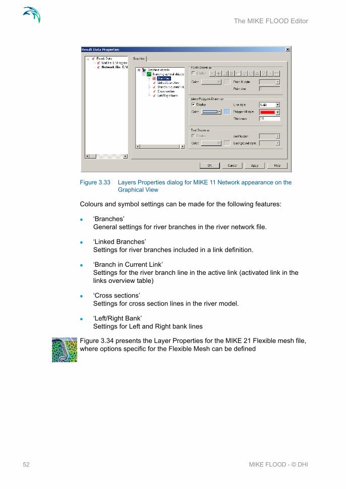
Figure 3.33 presents the Layer Properties for the MIKE 11 Network file and branch linkages.
51
The MIKE FLOOD Editor
Figure 3.33 Layers Properties dialog for MIKE 11 Network appearance on the Graphical View
Colours and symbol settings can be made for the following features:
‘Branches’General settings for river branches in the river network file.
‘Linked Branches’Settings for river branches included in a link definition.
‘Branch in Current Link’Settings for the river branch line in the active link (activated link in the links overview table)
‘Cross sections’Settings for cross section lines in the river model.
‘Left/Right Bank’Settings for Left and Right bank lines
Figure 3.34 presents the Layer Properties for the MIKE 21 Flexible mesh file, where options specific for the Flexible Mesh can be defined
52 MIKE FLOOD - © DHI

The Graphical Layout
Figure 3.34 Layer Properties dialog for MIKE 21 FM mesh file appearance in the Graphical View
Options available for the Flexible Mesh settings are:
Draw Mesh:Activate / de-activate the drawing of the 2D mesh
Contour Type:Defines the contours presentation. Options are: Box contour with or with-out transparency, Shaded contour or no control.
Isolines:Draw isolines in the view.
Miscellaneous:Options for drawing of 2D Mesh, activate colour palette/legend.
Mesh Styles:Miscellaneous options for Mesh features presented in the Graphical View.
Line Thickness:Line settings for drawing of the 2D Mesh
The Graphical settings page for MIKE 21 Flexible mesh model is presented in Figure 3.35.
53

The MIKE FLOOD Editor
Figure 3.35 Layer Properties dialog; Graphical settings page for MIKE 21 FM mesh file coupling
Graphical settings can be made for:
‘Links’Line definition for all link lines defined for the MIKE 21 FM model.
‘Current Link’Settings for the link line in the selected/active link in the Graphical view (active link in the links overview table).
‘Selected Point’Symbol definition for the single active point in the actual MIKE 21 FM link (active point selected in the MIKE 21 coordinates table for the selected link)
3.4.6 Add/Remove images...
This menu controls image files to be presented as layers in the Graphical View.
It is possible to display the following types of files:
graphical image files: *.bmp, *.jpg and *.gif.
GIS shape files: *.shp.
XYZ ASCII files: *.xyz
MIKE 11 network files: *.nwk11
mesh files: *.mesh
dfs files: *.dfs0, *.dfs2
54 MIKE FLOOD - © DHI

The Graphical Layout
Enhanced metafiles: *.emf
For each of the different files some of the display settings may be edited by clicking the ‘edit’ button found in the same row as the image file to be edited.
Figure 3.36 The Add/Remove Images dialog
Images may be added or removed using the two buttons in the upper right hand corner. inserts a new image line and removes an existing line from the table.
The second tab-page in this dialog is the standard Overlay manager for Layer files presented in the Graphical view and identical in behaviour and perfor-mance to the overlay manager presented and described in the ‘Add/Remove layers...’ section (see Figure 3.29).
3.4.7 Link river branches to MIKE 21
The MIKE FLOOD interface has an automatic linkage tool available for linking the river branches in MIKE HYDRO River or MIKE 11 to MIKE 21.
Several different linkage types can be processed using this tool:
Lateral links
Standard and Structure links
55

The MIKE FLOOD Editor
Side Structures Link
The Automatic selection and definition of Lateral Standard/Structure and Side Structure links are made through the ‘Link River Branch to M21...’ dialog, which can be opened from the Graphical view, right-mouse pop-up menu. This dialog is presented in Figure 3.37 below:
Figure 3.37 The ‘link branch to MIKE 21’ sub-menu. Note that for a lateral link two chainages are required whereas for standard/structure links only infor-mation on whether the link is to be applied to the upstream or the down-stream end of a branch is needed
Once a link has been established, the location of the link may be inspected by stepping through the link in the M21 coords table, whereby the active cell/point is highlighted in the graphical view and thereby it can be ensured, that links are defined according to expectations.
Lateral link definitionThe lateral link requires the user to supply the river branch name and the topo-ID used. River name can be selected from the drop-down selection box and the Topo-ID as defined in the network file is then listed in the Topo ID field.
A lateral link is generated for a user-defined length of the river. Upon selec-tion of the river name and Topo ID the ‘Chainage from’ and ‘Chainage to’ fields are automatically defined with the start and end chainage of the river as defined in the River network file. If it is requested to only include a part of the
56 MIKE FLOOD - © DHI

The Graphical Layout
actual river in the lateral link then it is required to adjust the chainage-values to adjust to the specific reach where the link must be defined.
The determination of which 2D cells/elements are to be included in the link can be made either by use of an external file, or from an automatic cell selec-tion based on the extent of the cross sections in the river reach.
Lateral link line from External file:This option requires the user to supply a *.xyz ASCII file, or a shape file containing one single polyline (only the x and the y values are required). The *.xyz file should be space delimited and should not have any com-ments within it. Only one link line per file can be processed.
Lateral link line from Digitized river:For the automatic cell selection the user must specify whether the actual linkage are to be made along the centre line of the river, along the right side or the left side of the river defined by the left or right levee definition in river cross sections. Cross sections are generally defined such that Marker 2 represents the centre line and Markers 1 and 3 represents the Left and Right levee posi-tions respectively.Note that it is also possible to create lateral linkage lines on both right and left side in only one operation.
A lateral link can be automatically divided in a number of links using the ‘Number of Segments’ field. This variable defines the number of sub-seg-ments the actual river reach will be divided into during link-generation, and an equivalent number of lateral links are then automatically generated and added to the overall links-table.
Using the Number of Segments variable, each of the links generated will be defined from sub-reaches of the total river reach length with sub-reach lengths calculated as:(Chainage To - Chainage From)/NumberOfSegments.
Based on the information entered by the user, the tool automatically selects either:
the MIKE 21 grid cells intersected by the left/right/centre line for the rec-tangular grid version, or
if Flexible Mesh is applied, the coordinates of the left and the right end points of the cross sections.
Implicit structure or standard structure link definitionThe definition of a Standard link or a Structure link requires the user to specify the branch name (from the drop-down selection box) and the Topo-ID initially.
57

The MIKE FLOOD Editor
Secondly, it must be defined whether the actual link is to be applied at the upstream end of the river (Lowest Chainage) or at the downstream end of the river (Highest Chainage).
Note that for Implicit Structure link, a link upstream and a link downstream are automatically generated.
The link generation routine creates a link between the river at the selected point and one or more 2D calculation grids/elements depending on the width of the cross section at the connection point and the size of grids/elements in the 2D model.
Side structure link definitionThe Side Structure Link definition requires the specification of the location of the side structure in the network file. That is, the River Name, the Topo ID as well as the Chainage where the actual Side Structure has been defined in the Network file (the structure chainage is supplied in the ‘Chainage From’ field).
In the lowest section of the dialog, a selection can be made on which side of the river the actual side structure will be linked (Right or Left) and additionally, the distance from the centre-line of the river is given, which determines how far away from the river the side structure branch in MIKE 11 will be connected to the 2D model area.
The link generation routine typically creates a link with just one M21 coordi-nate set - indicating that the link is only using a single 2D cell. However, if additional cells are required for linking (due to stability problems or other issues) it is possible to manually add additional coordinate sets to the M21 coordinate table in the lowest section of the dialog.
3.4.8 Block out river cells...
If cross sections of the rivers in a set-up are generally wider than one cell size in the 2D Grid, then it may be appropriate to block out the cells in the 2D bathymetry lying within the main river bed and hence avoid, that any flow cal-culation is performed by the 2D model in these cells. Thereby, it can be ensured that the water body within the main river is not included twice in the coupled model simulations.
Blocking out cells in the 2D bathymetry is a process where single or multiple cells are set equal to the ‘Land Value’ defined in the bathymetry editor, and therefore, the blocking out of cells requires the user to edit the MIKE 21 bathymetry in the grid editor.
58 MIKE FLOOD - © DHI

The Graphical Layout
The MIKE FLOOD interface can (based on the cross sectional widths or external files) identify and select all the 2D grid cells obtained as a function of the defined blockage option, and the selection is exported to a so-called selection-file. This selection-file may then subsequently be used in the grid editor to ease the selection and editing of cells to be blocked within the main river bed. To access the selection tool for blocking out cells simply right click in the graphical view and select the ‘Block out river cells’ menu item. The dia-log that appears is presented in Figure 3.38.
Figure 3.38 The dialog box for selecting which cells to block out in the MIKE 21 bathymetry
Multiple options for selection of 2D grid cells are available:
Blocking from cross sectional widthSelected grid cells will be fully located within a polygon deliniated by the left and right embankment lines (defined by markers 1 and 3 in cross sections) within the linkage reach.It is important to notice, that the river width can be smaller than the grid cell size in the 2D model and in that case, no cell will be selected as this option per default requires that the entire cell must be covered by the embankment polygon. Consequently, the possibility for obtaining a selec-tion of cells with ‘gaps’ present is big for smaller river applications.To avoid this problem and secure that a full, connected line of cells are selected from this option, it is possible to activate the ‘Apply minimum width of one cell’ option, which will secure that even for very small and narrow rivers, at least cells following the river centre line will be selected at locations where the river width is smaller than the grid cell size.
59

The MIKE FLOOD Editor
Blocking of cells intersected by river center lineChoose this option to select only the grid cells which are overlaid by the river centre line.This option secures that a full, connected line of cells are selected with-out including any information about the local width of the river.
Blocking based on external filesSelection of cells can be made from external files (either *.xyz ascii file or shape-file). Two external files are required in order to define the area between right and left side of the river where cells shall be selected.
The block out tool must be applied to each river reach separately, as the block out reach is selected based on the river name, the topo-ID and the upstream/downstream chainages.
The selection file is a dfs2 file with the extent of the 2D bathymetry and a value of 1 in all selected cells as illustrated in Figure 3.39.
Figure 3.39 A selection file opened in the grid editor of MIKE Zero
As MIKE FLOOD can be used also with nested grids (provided a nested MIKE 21 is available) the selection tool may export multiple files for the same river reach i.e. a selection file for each grid in the MIKE 21 set-up. To distin-guish between these different selection files MIKE FLOOD inserts the area number at the end of the file name e.g. if the file name ‘selection.dfs2’ is cho-sen the actual selection files are named ‘selection_1.dfs2’, selection_2.dfs2, etc. depending on the number of nested grids in the MIKE 21 set-up.
60 MIKE FLOOD - © DHI

The Graphical Layout
Step by step procedure for blocking out cells in the river bed
1. In the MIKE FLOOD graphical view right click and select the ‘Block out river cells...’ option (see Figure 3.40).
Figure 3.40 Accessing the blockage tool in MIKE FLOOD
2. In the dialog that appears select the river reach that the blockage is to be applied to. Please ensure that the river name is typed correctly and that the correct topo-ID is also supplied. If chainages are given which are beyond the river reach the values are modified to coincide with the reach ends. Also supply the name to be used for the selection file including the .dfs2 extension (see Figure 3.38).
When everything is defined, pressing OK creates the requested .dfs2 selection file. Note, that only one river can be saved to a selection file and hence, if multiple rivers are to be blocked out, multiple selections files have to be created using this tool.
3. Open the bathymetry file used in the MIKE 21 set-up. The file may be accessed through a right-click on graphical view and selecting “Edit topography”. This automatically opens the bathymetry file in the Grid Edi-tor. The file can also be opened from the ‘file -> open’ menu of MIKE Zero or through the MIKE 21 interface by clicking the ‘view’ button found in the bathymetry menu. The latter automatically opens the bathymetry
61

The MIKE FLOOD Editor
file in the Grid Editor.
4. With the bathymetry file as the active window in MIKE Zero it is possible to access the menu ‘Tools -> Load Selection’ found in the main menu bar of MIKE Zero. At this point you are prompted for the selection file. Browse for the selection file previously generated remembering that the file name has been augmented with a number indicating the area num-ber. The selected cells will by now be highlighted in the grid editor.
5. Access the ‘set value’ through the ‘Tools’ menu of the main MIKE Zero tool bar and provide the land value of the dfs2 file in the active box (see Figure 3.41).
6. Save the bathymetry file under a different name to ensure that the origi-nal data is not overridden.
7. Repeat the procedure for all rivers requiring blocking out of cells.
8. In the MIKE 21 editors bathymetry menu select the new edited bathyme-try.
Figure 3.41 The set value dialog. Choose the appropriate land value for the dfs2 file
62 MIKE FLOOD - © DHI
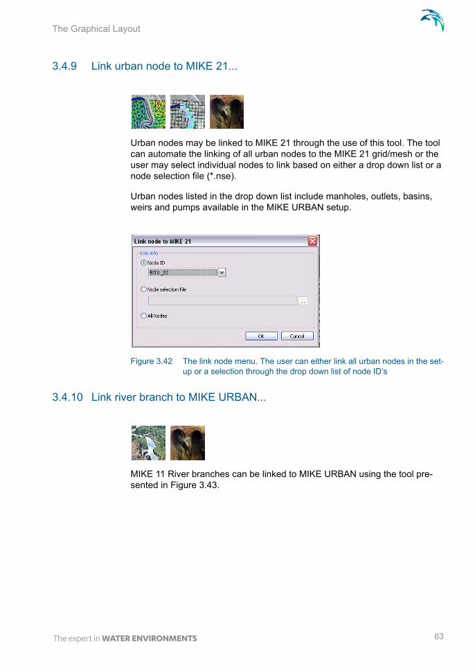
The Graphical Layout
3.4.9 Link urban node to MIKE 21...
Urban nodes may be linked to MIKE 21 through the use of this tool. The tool can automate the linking of all urban nodes to the MIKE 21 grid/mesh or the user may select individual nodes to link based on either a drop down list or a node selection file (*.nse).
Urban nodes listed in the drop down list include manholes, outlets, basins, weirs and pumps available in the MIKE URBAN setup.
Figure 3.42 The link node menu. The user can either link all urban nodes in the set-up or a selection through the drop down list of node ID’s
3.4.10 Link river branch to MIKE URBAN...
MIKE 11 River branches can be linked to MIKE URBAN using the tool pre-sented in Figure 3.43.
63

The MIKE FLOOD Editor
Figure 3.43 The Link River Branches to MIKE Urban collection system dialog
Select the type of coupling from the radio buttons and thereafter; select the river branch to be linked from the branch list drop-down menu, specify the MIKE 11 chainage of the link location and finally, select the ID for the urban node which shall be coupled from the Urban ID drop-down selection menu.
3.4.11 Export links to selection File...
The ‘Export Links to Selection File’ is a feature which exports MIKE 21 grid cells for all or selected links in the Coupling file to a dfs2 grid file. The selec-tion file generated is then typically used in the grid editor as a selection file when editing for instance bathymetry or model inputs such as resistance or eddy viscosity grid files.
This feature is only available for couplings with MIKE 21 Rectangular grid.
64 MIKE FLOOD - © DHI

The Graphical Layout
Figure 3.44 Dialog for Exporting linked MIKE 21 rectangular grid cells to a grid selection file
To generate a Selection file for Linked cells do the following:
Define the file name for the selection file. Output file from this tool is a 2D rectangular grid file and hence, file extension must be ‘.dfs2’
Select the type of links to be included in the exported links file (specific link type or simply All links in the model).
In the ‘Apply To’ box it can be defined whether all links of the selected type in the model should be included in the export process or only a sub-set of links should be included. In the latter case, use the ‘Selected links of requested type’ and press the ‘Select Links...’ button to open the Links selection dialog (section 3.1.7).
Figure 3.45 below presents an example of a grid file generated from the Export Links to Selection file tool. The present example includes ‘All’ links in the actual setup.
65

The MIKE FLOOD Editor
Figure 3.45 Example of selection file generated using the export linked MIKE 21 rectangular grid cells
The cells exported to the selection file are always defined with a value of 1 in order to use them for selections in the grid editor.
3.5 Details on Standard / Structure Links Options,
The options listed here are only applicable for Standard and Structure links.
Figure 3.46 Overview of options for standard and structure links. Note that the first column is carried over from the Definition page and cannot be edited
The first column in the table is carried over from the Definition page and indi-cates the type of link for all links defined in the coupling file. The type defini-tion cannot be edited.
66 MIKE FLOOD - © DHI

Details on Standard / Structure Links Options,
Sorting of linkages is possible in the table by double-clicking on the column headers of either the Link type or the River name columns.
Columns two and three contain the location of the link. That is, the River name and the chainage of the river where the link has been defined.
The Link Options page includes the option of searching for a specific link in the list using a string search for either river names or urban ID’s. The Search Link feature as illustrated in Figure 3.47 is activated by pressing keys ‘CTRL+F’ or through the main menu; Edit -> Search.
Figure 3.47 The Find Link dialog available in Link Details pages
3.5.1 Mom fact
‘Mom Fac’ is an abbreviation for Momentum Factor. The Momentum Factor is active for Standard Links only and applied to the momentum terms in MIKE 21.
Momentum Factor of 1 means full momentum transfer through the link, whereas a value of 0 means that momentum transfer is not guaranteed.
Note that even if the factor is set to 0, the source term applied to the continu-ity equation still creates some momentum. While this is sufficient in cases where conservation is not critical (such as over weir structures or for very large 2D cell size relative to the river flow capacity), it will not be accurate enough for all cases. On the other hand, in some instances model stability may be improved by removing the momentum terms.
Momentum is disabled for the lateral links because of the conceptual difficul-ties associated with lateral flows in a 1D model.
For the structure links, momentum is preserved via the implicit terms and this parameter is not applicable.
3.5.2 Ext fact
‘Ext Fac’ is an abbreviation for Extrapolation Factor. For standard links, the extrapolation factor has a default value of 0. This factor controls the time pre-
67

The MIKE FLOOD Editor
dictor in MIKE 11, which establishes MIKE 21 link values for the next time step. If factor is set to zero, the same value at n+1 will be used as at n. Note! If the last q point in the linked branch is a structure, this factor is set to zero by the calculation kernel.
The extrapolation factor is not applied for lateral links or for structure links. For more information, see the scientific documentation (8.1 Hydrodynamics - Standard Links (p. 105)).
3.5.3 Add / replace momentum terms
This option is available for structure links.
If the momentum terms are replaced, flow conditions calculated in MIKE 11 override flow conditions in the MIKE 21 cell.
If momentum terms are added, the flow conditions calculated in MIKE 11 are added to the flow conditions in the MIKE 21 cell.
To illustrate, consider a situation where a weir structure in MIKE 11 repre-sents a road embankment in a MIKE 21 grid (similar to that shown in Figure 2.3). The MIKE 11 structure flow would replace the MIKE 21 flow con-ditions.
Next, consider the same situation except with a culvert located under a sec-tion of the road. The culvert structure would be modelled in MIKE 11 (in a separate branch to the weir) and added to the flow conditions in the MIKE 21 cells. As long as this culvert structure link is listed in the coupling file after the weir structure link, both weir and culvert flow would be included in MIKE 21.
Note: the add / replace options mean that the order in which structure links are listed in the couple file will affect the model behaviour. By specifying “Replace” in a link, all previous link inflows from previous links will be overrid-den. Also note that MIKE 11 can handle composite structures e.g. a culvert and a weir at the same location. This may be used to handle a complex situa-tion with flow both over topping and flowing under an embankment. The defi-nition of such a structure is handled in MIKE 11 and does not require two explicit couplings pairs in the MIKE FLOOD interface.
3.5.4 Depth adjustment
If depth adjustment is active, flow through a link is distributed into the MIKE 21 cells according to the water depth in those MIKE 21 cells. This is consid-ered appropriate for links on natural terrain or channels, but may not always be applicable for structures.
68 MIKE FLOOD - © DHI

Details on Standard / Structure Links Options,
3.5.5 Activation depth (minimum and maximum)
The activation depth is valid only for the zero flow (XFLOW=0 and YFLOW=0) links. If specified then these links will be turned off once the acti-vation depth is reached. A maximum and minimum value is available to grad-ually apply the flow conditions over a range to minimise instabilities. Note that the feature is only available with a MIKE 11 link.
If the minimum and maximum values are set to zero, the activation depth facility is inactive.
3.5.6 Exponential smoothing factor
The parameter introduces an exponential smoothing of the water level values transferred from one model to the other model. A value of 1 indicates no smoothing whereas a value closer to 0 creates strong smoothing in the model. Values are only valid in the range [0;1].
The exponential smoothing is available for the following link types:
Lateral links. The smoothing is applied for the MIKE 11 and the MIKE 21 water levels separately.
Standard links. The smoothing is applied to the MIKE 21 water level transferred to MIKE 11. Thus a lag may be evident when comparing MIKE 11 water levels at links with the corresponding linked cells/ele-ments in MIKE 21.
Implicit structure links. As above the smoothing is applied to the MIKE 21 water level and thus a deviation (time lag) may be present at the link points.
Urban link from MIKE 21 to an outlet in the sewer model. The smoothing is applied to the MIKE 21 water level transferred to MIKE URBAN.
Urban link from MIKE 21 to an inlet in the sewer model. In this case the smoothing is applied to the node water level and the MIKE 21 water level used for calculating the interacting discharge.
River urban link when either a sewer outlet is coupled to a MIKE 11 loca-tion or when a water level boundary in MIKE 11 is coupled to a node in MIKE URBAN(MOUSE). For a sewer outlet the smoothing is applied to the MIKE 11 water level while for a water level boundary in MIKE 11, the water level in the MIKE URBAN manhole is smoothed.
Side structure link. Smoothing is applied as described for Standard links above.
69

The MIKE FLOOD Editor
The smaller the value the greater the smoothing will be. The parameter impacts the dynamics by smoothing out steep gradients (in time) through the links.
In general the exponential smoothing factor should be adjusted when a struc-ture exhibits unstable behaviour (oscillates wildly). The following approach should be followed if a link shows instability:
1. Set the exponential factor to 0.2 – 0.4
2. Run the model
3. If a link still “misbehaves” (i.e causes a blow-up OR the discharge hydro-graph is very 'noisy') then check the results file, the model link location, the MIKE 21 topographic grid, the coupling, etc. for problems, and incon-sistencies.
4. Re-run the model if changes are made.
5. If the link still “misbehaves” then the smoothing factor may be further reduced. Note that a small smoothing factor will cause a time lag in the transfer of the values from one model component to the other model component. As a rule of thumb the time scale at which the model changes over should be a factor greater than the time lag caused by the smoothing factor. As an estimate for the latter the following expression may be used:
(3.2)
where f = 0.001, is the smoothing factor and t is the model time step. The estimate is based on the time it takes for an initial deviation in the coupled models water level to be reduced to within 0.1% of each other.
6. Rerun the model.
7. If a small value of the smoothing factor is required, you need to satisfy yourself that the results are reasonable and the results for the overall model have not been significantly delayed.
T tflog
1 – log-------------------------=
70 MIKE FLOOD - © DHI

Details on Lateral Links Options
3.6 Details on Lateral Links Options
Except for the depth tolerance the options listed in this menu are only rele-vant for lateral links.
The depth tolerance may also be used in conjunction with the implicit struc-ture links.
The overview of the options in shown in Figure 3.48.
Figure 3.48 The overview for lateral links. Note that the link type is carried over from the ‘Definition’ page and cannot be edited
The first column in the table is carried over from the Definition page and indi-cate the type of link for all links defined in the coupling file. The type definition of link cannot be edited.
Columns two and three contain the location of the link. That is, the River name and the Upstream and Downstream chainages of the river where the lateral link is defined.
Sorting of linkages is possible in the table by double-clicking on the column headers of either the Link type or the River name columns.
Searching for a specific link is also possible in this page. The Search Link feature as illustrated in Figure 3.47 is activated by pressing keys ‘CTRL+F’ or through the main menu; Edit -> Search.
71

The MIKE FLOOD Editor
3.6.1 Side of river
Side of river defines whether the lateral link is a link on the left bank or the right bank of the river channel. The information in conjunction with the MIKE 21 topography is used to determine the levee height.
Left bank is equivalent to Marker 1 in the MIKE 11 cross-section editor
Right bank is equivalent to Marker 3 in the MIKE 11 cross-section editor
3.6.2 Method
The method defines how the flow is distributed between MIKE 11 and MIKE 21:
The CELLTOCELL method performs a flow calculation for each individ-ual point in the defined structure. Each calculated flow is then redistrib-uted to MIKE 21 and MIKE 11. This means that the number of MIKE 11 points doesn’t necessarily have to match the number of MIKE 21 cells.
The SIMPLE method performs a single calculation of flow, then distrib-utes that flow to each MIKE 21 cell and/or MIKE 11 computation (h) point. Note that this option is available for backward compatibility rea-sons. It is in general not recommended since it gives a uniform flow across the whole link which is typically far from the true flow picture.
The CelltoCell method is the default and is the only one available if linking with a flexible mesh.
3.6.3 Structure type
The structure type defines the type of flow calculation to be performed:
WEIR1: MIKE 11 Weir Formula 1 with friction term included.
WEIR2 (H): MIKE 11 Weir Formula 2 (Honma) with friction term included.
QHTABLE: A QH table is used, stored in an external file. Note that if using a CELL-TOCELL method, the Q in the QH table is the flow per unit width. Not available with the flexible mesh version of MIKE 21.
72 MIKE FLOOD - © DHI
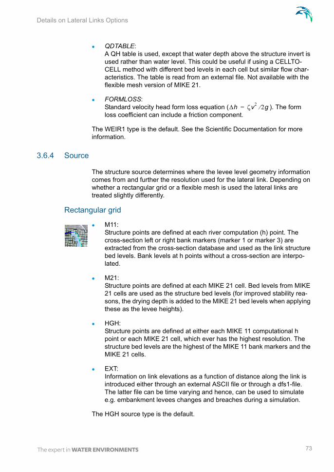
Details on Lateral Links Options
QDTABLE: A QH table is used, except that water depth above the structure invert is used rather than water level. This could be useful if using a CELLTO-CELL method with different bed levels in each cell but similar flow char-acteristics. The table is read from an external file. Not available with the flexible mesh version of MIKE 21.
FORMLOSS: Standard velocity head form loss equation ( ). The form loss coefficient can include a friction component.
The WEIR1 type is the default. See the Scientific Documentation for more information.
3.6.4 Source
The structure source determines where the levee level geometry information comes from and further the resolution used for the lateral link. Depending on whether a rectangular grid or a flexible mesh is used the lateral links are treated slightly differently.
Rectangular grid
M11: Structure points are defined at each river computation (h) point. The cross-section left or right bank markers (marker 1 or marker 3) are extracted from the cross-section database and used as the link structure bed levels. Bank levels at h points without a cross-section are interpo-lated.
M21: Structure points are defined at each MIKE 21 cell. Bed levels from MIKE 21 cells are used as the structure bed levels (for improved stability rea-sons, the drying depth is added to the MIKE 21 bed levels when applying these as the levee heights).
HGH: Structure points are defined at either each MIKE 11 computational h point or each MIKE 21 cell, which ever has the highest resolution. The structure bed levels are the highest of the MIKE 11 bank markers and the MIKE 21 cells.
EXT: Information on link elevations as a function of distance along the link is introduced either through an external ASCII file or through a dfs1-file. The latter file can be time varying and hence, can be used to simulate e.g. embankment levees changes and breaches during a simulation.
The HGH source type is the default.
h v2 2g=
73
The MIKE FLOOD Editor
Flexible mesh
For the flexible mesh the lateral link is divided up into segments. Each seg-ment being defined by two consecutive sets of coordinates for the lateral link. A discharge is evaluated across each segment and distributed in MIKE 11 according to the chainage values for the segment end points. The source parameter only controls from where the levee height should be extracted:
M11: The levee height is determined from the bank markers (marker 1 and 3) in MIKE 11.
M21: The levee height is defined by the topography in MIKE 21 (for stability reasons the drying depth is added to the topography values when defin-ing the levee height).
HGH: Takes the max of the MIKE 21 topography and the MIKE 11 bank mark-ers.
EXT: Information on link elevations as a function of distance along the link is introduced either through an external ASCII file or through a dfs1-file. The latter file can be time varying and hence, can be used to simulate e.g. embankment levees changes and breaches during a simulation.
The HGH source type is the default.
Please note: The levee height is not allowed to be below the MIKE 21 topog-raphy (at the linkage point) nor below the bed level in MIKE 11. Thus if the selection is such that this occurs MIKE FLOOD will use the limiting value.
3.6.5 Depth tolerance
This parameter is used to smooth out the transition when the flow over the lateral link changes direction. The parameter is also available for the implicit structures. In this case the parameter is used to describe the water level dif-ference across the structure at which point the discharge gradients are grad-ually suppressed. If such a suppression is not applied the model may experience numerical instability. The suppression varies with the water level difference and is only active when the water level difference is less than the depth tolerance.
3.6.6 Structure coefficients
Coefficients controlling flow through the link structure include the weir coeffi-cient (default = 1.838 m1/2/s ~3.329 ft1/2/s ), the weir exponent coefficient (default = 1.5), the Manning’s n friction coefficient (m1/3/s) and the form loss
74 MIKE FLOOD - © DHI

Details on Lateral Links Options
coefficient. Note that friction can be included in the weir equations - see the scientific documentation for more information.
3.6.7 External files for lateral links
Two types of lateral link variables can be defined by the usage of external files:
Structure Source
Structure Type
Structure sourceIf the structure source has been selected to ‘EXT’, an external file must be specified (either a txt-file or a dfs1-file) to define the level of embankment along the lateral link. The required format of the Ascii (txt) file is shown in Table 3.2. If a dfs1-file is required there is a possibility for creating such a file using the ‘Levee Breach Generation’ tool from the MIKE Flood Toolbox (Found at: File->New->MIKE Flood->MIKE Flood Toolbox).
Structure typeIf the structure type has been defined as a QH Table or a QD Table, an exter-nal file is specified with information on Chainages and Water levels (QH) or Water Depths (QD). The format of the QH or QD file is shown in Table 3.3.
Table 3.2 Format of External Structure File
File Input Example Description
// External file 40.0 2.0100.0 0.0500.0 0.01000.0 2.0
‘//’ is a comment marker - as many comment lines as desired can be included in this file.
Line 1: Number of entries.
Line 2 onwards: Column entries, Space delimited - first column is chainage, second column is bed level (units according to user units for chainage and bed level respectively).
75

The MIKE FLOOD Editor
Note that values are space delimited.
3.6.8 Additional lateral Linkage feature; Linkage Level analysis
Defining a Lateral Link causes MIKE FLOOD to process the embankment levels along the link from the specified Source option. The processing of link elevations to be used during simulation takes place during the pre-processing of a simulation and as such, the link-levels are not directly known and availa-ble to the user.
Therefore, a feature for analysing the applied invert levels of lateral links in a simulation is available. This feature extracts information from all lateral links in the model and saves this information to an external file named ‘MFLat-eral.XNS11’ and saved in the folder where the MIKE 11 Sim11-file is located.
The cross section file format has been chosen for storing the link levels data and when opening the file, information is visible for each lateral link in the model as described below.
The River Name of the links has been defined as the River Names in the cross section file and the Topo ID’s in the file has been used to include infor-mation on the different links given by:
M11 Chainage (actual MIKE 11 grid points of linked river reach)
M11 Percentage (the above locations normalized)
Table 3.3 Format of External QH File
File Input Example Description
// HQH file5 3
0.0 1.0 2.00.0 0.1 0.2 0.31.0 0.3 0.3 0.32.0 0.4 0.5 0.73.0 0.9 1.9 2.95.0 10.0 20.0 50.0
‘//’ is a comment marker - as many comment lines as desired can be included in this file.
Line 1: Number of upstream levels (rows = nr) and num-ber of downstream levels (columns = nc), space delim-ited.
Line 2: List of nc values of downstream levels, space delimited.
Line 3 onwards (nr lines): List of nc values of upstream level, then nc values of discharge, space delimited.
Notes:
If QHTABLE, levels are water level
If QDTABLE, levels are water depth
If CELLTOCELL, discharge is flow per unit width
Units according to user units for water level, water depth, discharge and flow flux
76 MIKE FLOOD - © DHI

Details on Lateral Links Options
M21 Chainage (the cell height associated with the MIKE 21 cells/seg-ments mapped onto the MIKE 11 grid locations)
M21 Percentage (the above normalized with respect to the MIKE 11 chainages)
Struc Chainage (the resulting structure link mapped onto the MIKE 11 grid locations)
Struc Percentage (the above normalized with respect to the MIKE 11 chainages)
The entries listed above is added with a suffix; ‘RIGHT’ or ‘LEFT’ depending on which side of the river the lateral link is defined for (‘Left M11 Chainage’).
Chainages/length for the link is then included in the ‘X’-column and the level elevations are included in the ‘Z’-column for each ‘cross section’ in the file, and the inverts of each of the links may now be investigated for possible inconsistencies.
Please note that all chainages indicate the mapping onto the MIKE 11 grid points. They do not reflect the actual width of the levee segments used. The latter depends on the source for the levee height. If the source is MIKE 21 the length is based on the cell size. If MIKE 11 is the source then the distance between the grid points control the levee segment lengths.
MIKE Flood prior to Release 2011 can also save the lateral link elevations to an external file. In previous releases this feature generated an ASCII file instead of a xns11-file. The file created was named ‘MFLateral.txt’ and still contained the same information as the Xns11-file. The Ascii file has a format such that it can be directly imported into the cross section editor in which the levee height along each lateral link defined in the model can then be investi-gated.
To generate this ASCII file in releases prior to Release 2011 the following pro-cedure should be followed:
Set-up the MIKE Flood model
Place an empty file named "MFLateral.txt" in the same folder as where the *sim11 file is located.
Start a MIKE Flood simulation.
The ASCII file is exported in the first time step of the run. Once the first time step of the simulation has been completed the file in step 2 will have been overridden with values describing the inverts of the lateral links. Hence, if the purpose is primarily to generate and analyse the ‘MFLat-eral.txt’ file then the simulation can be stopped after one timestep.
77

The MIKE FLOOD Editor
Open a new cross section file (*.xns11) and import the “MFLateral.txt” using File -> Import -> Import raw data.
For compatibility reasons, the writing to an ascii file has been kept and hence, both a Xns11-file and an Ascii file are being automatically created from simu-lations made in the actual version of MIKE FLOOD.
3.6.9 Lateral links in rectangular grids and flexible mesh
Internally within MIKE FLOOD lateral links are treated differently depending on whether a rectangular grid or a flexible mesh is used.
Rectangular grid
When using the rectangular grid lateral links are treated in the following way
The h-grid points within the linked river reach are identified.
The linked MIKE 21 cells are given a chainage based on the cell size. That is the chainage runs from cell centre to cell centre plus additional contributions from the first and the last cell. The MIKE 21 chainages are subsequently normalised so that they span the lateral links chainage.
Depending on the method used the lateral structures will be set up according to the 2D cells or the river grid points. The chainage of the structures will be based on the chainages in the river.
The chainage of the structures are normalised so that they span the same as the river chainage. The code uses the location based on these normalised chainages to locate which cells and h-points match up with which lateral structure.
Flexible mesh
MIKE FLOOD with a flexible mesh treats the lateral links in the following way
The h-grid points within the linked river reach are identified.
The linked MIKE 21 elements are given a chainages based on the seg-ment chainage values. Each segment constitutes an internal lateral structure modelled as a weir.
Depending on the method used the lateral structures will be set up according to the 2D topography or the river grid points. The chainage of the structures will be based on the chainages of the segments.
78 MIKE FLOOD - © DHI

Details on Urban Link Options
Mesh face-lines which have been defined as a link through the MIKE Flood coupling is automatically being defined as a closed boundary inside the FM-calculation engine such that the only flow allowed to cross these face-lines are flow across the link between MIKE 11 and MIKE 21 FM.
3.7 Details on Urban Link Options
There are a number of options available for an urban coupling as illustrated in Figure 3.49.
Figure 3.49 The overview page for Urban Link options
The first column in the table is carried over from the Definition page and indi-cate the type of link for all links defined in the coupling file. The link type defi-nition cannot be edited.
Column two contains the defined Urban ID of the link.
Sorting of linkages is possible by double-clicking on the column headers of either the Link type, the Urban ID or the Type columns.
Searching for a specific link is also possible in this page. The Search Link feature as illustrated in Figure 3.47 is activated by pressing keys ‘CTRL+F’ or through the main menu; Edit -> Search.
Urban Link options are described below.
3.7.1 Type
There are four different types of links available.
M21 to inlet: A link between the overland and a manhole/basin in MIKE URBAN. The urban ID is the node ID in this case.
79

The MIKE FLOOD Editor
M21 to outlet: A link to an outlet in MIKE URBAN. The urban ID is the node ID in this case. The water level in MIKE 21 is used as a boundary condition in MIKE URBAN which subsequently runs a time step and evaluates the boundary condition. From the time step taken, the discharge is calcu-lated in MIKE URBAN and introduced as a source in MIKE 21. Thus the MIKE URBAN time step has the discharge as output.
Weir to M21: A link between MIKE 21 and a MIKE URBAN weir discharging out of the sewer/storm water system. The urban ID is the weir ID.
Pump to M21: A link between a MIKE URBAN pump discharging out of the sewer/storm water system and the MIKE 21 topography. Urban ID is here understood as a pump identifier.
The links may be coupled to multiple cells in the MIKE 21 rectangular grid or alternatively an area in the flexible mesh. If the latter is used at least 3 points must be supplied to constitute an area (polygon). If only one point is supplied in a given urban link then the discharge is introduced as a single source/sink in the in the element of the mesh where the link is defined. If three points or more are supplied, then the discharge is distributed as sources/sinks in the elements enclosed in the polygon defined by the link points.
It is important to note that the remaining parameters are only applicable for the MIKE 21 to inlet type of couplings.
3.7.2 Inlet method
The exchange of water between MIKE 21 and an inlet may be described through 3 different methods:
Orifice equation: The flow between MIKE URBAN(MOUSE) and MIKE 21 is governed by a standard orifice equation.
Weir equation: The flow is described through a weir equation.
Exponential function: The flow is governed by a simple exponential function.
Curb inlet function: The flow between MIKE URBAN and MIKE 21 is transferred at a grate or inlet from a surface overland flow network to the sub-surface pipe net-work. The transfer capacity of the connection is specified as a DQ-rela-tion (tabular data type). When water is transferred to the surface from the sewer pipe network the flow is calculated with the orifice equation.
80 MIKE FLOOD - © DHI

Details on Urban Link Options
Depending on the calculation method used additional information is required.
By default the MIKE 21 ground level is used as the level of the manhole inlet. If the user selects to do so the manhole ground level may be defined by the MIKE URBAN model. Though the latter will always be overruled by the MIKE 21 ground level if this is higher. For a grid based 2D model the MIKE 21 ground level is by default the highest coupled grid cell of a particular coupling. The latter may be changed through the use of a MIKE 21 option parameter. To achieve the latter you must edit the options paragraph of the hydrody-namic section in the MIKE 21 file (*.M21). The following keyword will control the crest elevation definition:
Mouse_Couple_Elevation_Definition = 0 // 0: highest level (default), 1: lowest level, 2: average level.
The *M21 file may be edited in any standard editor.
3.7.3 Max flow
This parameters gives an upper limit on the discharge that can flow through the urban link. If the exchange calculated from the flow equation is above this value the discharge is reduced to this value. Only applicable to inlet cou-plings.
3.7.4 Inlet area
The inlet area is only used when applying the orifice equation for describing the flow exchange between the urban and the 2D grid/mesh. The greater the cross sectional area the greater the conveyance capacity of the coupling. This parameter corresponds physically to the area of the man-hole cover. When coupling to a basin this value is neglected.
3.7.5 Crest width
The crest width is used when the flow exchange is described through a weir equation. The weir crest should typically be the circumference of the manhole cover.
3.7.6 Discharge coefficient
The discharge coefficient is a non-dimensional factor that may be used to scale the weir flow and the orifice flow. By default the parameter should be set to 1.
81
The MIKE FLOOD Editor
3.7.7 Scaling factor
Only applicable if the simple exponential expression is used to describe the flow exchange. The scaling factor has a linear effect on the discharge. Thus an increase in this value will generate a larger flow for a certain water level difference in the urban and the MIKE 21 model.
3.7.8 Exponent factor
Only applicable if the simple exponential expression is used to describe the flow exchange. An increase in the exponent factor has a strong impact on the discharge. An increase in this value will generate a larger flow for a certain water level difference in the urban and the MIKE 21 model.
3.7.9 Qdh factor
A parameter indicating the water level difference from which the calculated discharge should be progressively surpressed. May be used for stabilizing set-ups where the instability is caused by a small difference in the water level in the two coupled models. Only applicable at inlet couplings. See the Scien-tific Background 8.5 for additional description.
3.7.10 Freeboard
The freeboard defines a critical water level (Invert level- Freeboard) at the connection node in the pipe network below which the defined DQ relation apply. For submerged and reverse flow (surcharge), the transfer capacity of the connection reverts to a standard orifice relationship.
3.7.11 Capacity curve DQ Relation
The DQ relation specifies the depth based capacity curve for the curb inlet. Values must be monotonously increasing in depth and discharge starting at (0,0). For depths in excess of the maximum value specified in the last row of the table, the last corresponding discharge is used. Positive discharge is con-sidered to flow from MIKE 21 into MIKE URBAN (overland to sewer network).
3.8 Details on River - Urban Link Options
The options page for River - Urban Links is presented in Figure 3.50.
82 MIKE FLOOD - © DHI

Details on River - Urban Link Options
Figure 3.50 Overview page of River - Urban Link Options
The first column in the table is carried over from the Definition page and indi-cate the type of link for all links defined in the coupling file. The link type defi-nition cannot be edited.
Columns two, three and four contain the location specifications of the link. That is, the River name, The Urban ID and the river chainages where the river-urban link has been defined.
Sorting of linkages is possible in the table by double-clicking on the column headers of either the Link type, the River name or the Urban ID columns.
Searching for a specific link is possible in this page. The Search Link feature as illustrated in Figure 3.47 is activated by pressing keys ‘CTRL+F’ or through the main menu; Edit -> Search.
The options for the river urban links essentially consists of choosing the river urban link type. There are four possibilities
MIKE 11 water level boundary. This link is used when coupling a water level boundary in MIKE 11 to an inlet in MIKE URBAN(MOUSE). The user specifies the MIKE 11 bound-ary location through the use of a branch name and a chainage and the node ID of the inlet to be coupled.
MIKE URBAN outlet to MIKE 11. The user selects the node ID of an outlet in the sewer network along with the MIKE 11 location. Note that the MIKE 11 location should not coincide with a water level boundary in the river network (use the previous link type in this case). The link should be located along a MIKE 11 branch.
MIKE URBAN pump to MIKE 11. The user selects a pump which discharges out of the sewer system along with a MIKE 11 location. This type of link is uni-directional i.e. only from MIKE URBAN(MOUSE) to MIKE 11.
MIKE URBAN weir to MIKE 11. The location is defined through the ID of the weir and a branch name along with a chainage in MIKE 11. This type of link is uni-directional i.e. only from MIKE URBAN(MOUSE) to MIKE 11.
83

The MIKE FLOOD Editor
Note that the context sensitive menu (right click) in the graphical overview grants access to an automatic linkage tool as shown below.
Figure 3.51 The automatic linkage tool to be used for setting up links between MIKE 11 and MIKE URBAN. Note that the functionality of combo boxes varies depending on the selections in the upper part of the dialog
The linkage tool may be used for all of the above listed link types. The user selects the type of link along with a specific branch for linking. The Urban ID combo box then lists the types of objects of the required type (pump, weir etc.). Once an urban ID has been selected the user may click on the Get Chainage button which will locate the nearest point on the selected branch. The procedure may be repeated for each link to be set-up.
3.9 Details on Side Structure Link Options
Side structures Link options page is presented in Figure 3.52.
84 MIKE FLOOD - © DHI

AD Components
Figure 3.52 Overview page for Side Structure Link Options
The first column in the table is carried over from the Definition page and indi-cate the type of link for all links defined in the coupling file. The link type defi-nition cannot be edited.
Sorting of linkages is possible in the table by double-clicking on the column headers of either the Link type or the River name columns.
Columns two and three contain the location specifications of the link. That is, the River name and the river chainage where the Side structure link is located.
Searching for a specific Side structure link is possible. The Search Link fea-ture as illustrated in Figure 3.47 is activated by pressing keys ‘CTRL+F’ or through the main menu; Edit -> Search.
Flow characteristics for side structures are primarily defined from the struc-ture definitions in the MIKE 11 model (structure geometry, loss factors etc.). Two parameters can be defined for the Side Structures link in the couple file:
Depth Adjustment (further details in section 3.5.4), and
Exponential smoothening factor (further details in section 3.5.6 and in the scientific documentation).
3.10 AD Components
The page is activated by selecting the tick box on the definition page. In this page the user simply lists the components in the MIKE URBAN(MOUSE), MIKE 21 and the MIKE 11 set-ups and match the individual components.
85

The MIKE FLOOD Editor
Note that the component names available may be listed by clicking in the component name fields.
It is possible (but not recommended) to have non-matching components in the three models i.e. a component may only be available in two of the three models. In such cases the component field is left blank for the model without the specific component. The other two models will assume that water enter-ing from the model without the specific component will have a concentration (temperature) equal to the existing components concentration (temperature).
Along with the matching components the user must supply conversion factors between the various models. The intrinsic units for concentrations and tem-perature are
MIKE 11: g/m3 and oC
MIKE URBAN (MOUSE): g/m3 and oC
MIKE 21: The concentration is defined by the user and the temperature is oC
The conversion factors are defined as follows
The internal MIKE 21 concentration is multiplied by the conversion factor between MIKE 21 and MIKE 11 before being supplied as a boundary condition in MIKE 11.
The internal MOUSE concentration is multiplied by the conversion factor between MOUSE and MIKE 11 before being supplied as a boundary condition in MIKE 11.
The internal MIKE 21 concentration is multiplied by the conversion factor between MIKE 21 and MIKE URBAN(MOUSE) before being supplied as a boundary condition in MIKE URBAN(MOUSE).
86 MIKE FLOOD - © DHI

Defining Result Files for a MIKE Flood Simulation
4 Simulation Results
Simulation results from a MIKE Flood simulation include output from the dif-ferent models being coupled through the MIKE Flood editor.
4.1 Defining Result Files for a MIKE Flood Simulation
The primary purpose of the MIKE Flood coupling editor is to couple different model-types for an optimal, integrated description of the flow conditions in the specific environment you are investigating. Consequently, the MIKE Flood editor does not include any options for defining result file names, and the out-put files from a MIKE Flood simulation is therefore generated using specifica-tions in the pre-defined model-setup files which are included in the coupled setup.
The MIKE FLOOD simulation will therefore produce result files following the specification by the user in the different model setup-files:
MIKE 21 (.m21)
MIKE 21 FM (.m21fm)
MIKE 11 (.sim11)
MIKE URBAN (.mup)
Consequently, simulation results will be divided into results from the individual model with e.g. surface flow calculated and stored in the MIKE 21 result files and e.g. river flow stored in the MIKE 11 result file. Results from the different models can be presented and analysed in one of the MIKE Zero post pro-cessing tools (e.g. Result-viewer or Plot composer) as described in Chapter 6.
4.2 Seamless Integrated 1D and 2D River Flooding Results
A feature for generating a ‘seamless’, 2-dimensional result-file, which includes a combination of results produced from the MIKE 21 Rectangular grid model and the MIKE 11 results is available.
87

Simulation Results
Specifications for the seamless result-file integrating the 2D and 1D simula-tion results is defined through the MIKE 11 User Interface using the HD Parameters file --> ‘Maps’.
Steps for producing a seamless result-file integrating MIKE 21 and MIKE 11 results into one 2-dimensional result-file (.dfs2) are:
Open the MIKE 11 simulation file to be used in the coupled simulation
Open the HD Parameter File included in the MIKE 11 project (.hd11)
Select the ‘Maps’ tab-page and activate the MIKE 11 mapping feature by activating the tick-box named ‘Generate Maps’.
Define your map (i.e. a 2-dimensional grid) by the Origo coordinates, Grid size definitions and Map file name (this file name will be the file name for the seamless integrated 1D and 2D simulation results)
In the ‘Item’ column, make sure to select the option ‘(h, p, q)’
Save the hd11-file and run eventually the MIKE 11 model to see, that the output-file (map) you obtain from your specifications are as expected with respect to location and resolution.
Close the MIKE 11 files and run the MIKE Flood simulation to create the result-file with result from both the 2D and 1D simulations.
Further details on the MIKE 11 mapping feature can be found in the MIKE 11 User Guide and the MIKE 11 Reference manual, App. 1.
88 MIKE FLOOD - © DHI

Define Model Layout
5 Running MIKE Flood- recommended Steps
Errors and inconsistencies in a model setup will occur. While every effort has been made to produce clear error messages, it can be difficult to keep track of all components in the model setup. To ensure that errors are minimised, we recommend following a clear, step by step procedure to develop and run MIKE FLOOD.
5.1 Define Model Layout
A MIKE FLOOD model is often a compromise between model resolution (grid/mesh size) and computational time required for a simulation. Note that computational time is mostly influenced by the total number of wet, computa-tional points that occur over an entire simulation. This means that a flood sim-ulation with a short duration, sharp peaked hydrograph will use much less computational effort compared to a long duration, flat peaked flood event. Consider this when deciding on grid resolution. Other things to consider include:
The 1D model extent. Ensure that the working area in MIKE 11/MIKE URBAN(MOUSE) includes the full 2D extent.
The 2D model extent
Where model boundaries will be located - remember that often a MIKE FLOOD link is more flexible than applying a boundary condition directly in MIKE 21
The alignment of the 2D grid - this may depend upon the alignment of main channels, flood plain features, etc.
The type of links to be used.
The geographical projection used must be identical for MIKE 11/MIKE URBAN(MOUSE) and MIKE 21.
5.2 Setup and Run 1D Models
MIKE FLOOD is a combination of MIKE 11/MIKE URBAN(MOUSE) and MIKE 21. Set up the individual models separately, then join them together using MIKE FLOOD.
It should be possible to completely define the 1D models that will be linked in MIKE FLOOD. This should be done to ensure that no errors exist in the 1D models. While the results of the simulation will not be correct, they may pro-vide an indication of potential problems.
89

Running MIKE Flood- recommended Steps
5.3 Setup and Run MIKE 21 Model
As for the 1D setups, ensure no errors exist in the MIKE 21 definition files. Run the simulation and ensure that the results are reasonable. For flood plain applications this may include running a completely dry set-up with closed boundaries.
5.4 Setup MIKE FLOOD
The model layout should already be decided upon, and the individual models should already have the components ready for running the MIKE FLOOD model. This step is to create the MIKE FLOOD couple file and define the links to be applied.
5.5 Run MIKE FLOOD Simulation
Note that the standard links and the lateral links are explicit (Courant condi-tions cannot exceed 1). It is likely that stability problems related to the links will occur in the initial simulations if the Courant number condition is exceeded. Do not be surprised if several adjustments of the links need to be made at this stage, or that the time step required is much shorter than you expected.
Check some of the tips available in this document (see Tips and Trouble-shooting).
Once an initial MIKE FLOOD simulation has been completed, the modeller should have a good appreciation of the model layout and its various compo-nents, and be aware of the potential problems that may crop up in subse-quent simulations and analyses.
90 MIKE FLOOD - © DHI

Run MIKE FLOOD Simulation
6 Pre- and Post-processing
It is envisaged that much of the pre- and post-processing of MIKE FLOOD will be done in a GIS. The GIS provides superior tools for the management and storage of large amounts of data, which are required for many flood plain applications. MIKE URBAN or MIKE 11 GIS are very powerful supplementary packages to be used in conjunction with MIKE FLOOD. However, not all GIS systems have specialised tools suitable for modelling (time series analysis, grid editing, surface interpolation etc.), so MIKE ZERO has its place in the modelling method. Standard spread sheets (EXCEL) are also useful for data management.
Links to external programs are available at present through MIKE ZERO. Linkage properties can be imported into MIKE FLOOD either through an external ASCII file (XYZ files from a GIS) or by cutting and pasting into the MIKE FLOOD interface.
The results from MIKE FLOOD (water levels, discharges, fluxes, AD compo-nents etc.) can be viewed using the Result Viewer (MIKE 21, MIKE 11 and MOUSE), Plot Composer and Data Viewer (MIKE 21) and MIKE VIEW (MIKE 11, MOUSE, MIKE URBAN). Also, MIKE ZERO allows MIKE 21 result files to be exported to an ARC-GIS ASCII input file. It is also possible to view the MIKE 21 result file in ArcGIS directly by using the DHI dfs2 plug-in to ArcMap.
The recommended tool to use is the Result Viewer, which is activated from MIKE ZERO (File- New - MIKE ZERO - Result Viewer). The viewer can pres-ent 1D, 2D and 3D results from different DHI Software models at the same time, including *.res11 result files from MIKE 11, *.prf result files from MOUSE and *.dfs2/*.dfsu result files from MIKE 21:
New files are added to the Result Viewer project by using Result Viewer - Projects - Add files to project and press the new “page” icon to the right. The “File Type” is a scroll-down menu, where the result file is chosen.
The work area is defined under Result Viewer - Projects - Work Area.
In order to display the results together, the various models need to be based on the same geo-reference. Thus, the MIKE 11 network and the pipe network must be described in the same UTM metric grid as the MIKE 21 bathymetry file.
The type of result data to display (contours and/or vectors) is selected in Result Viewer - Projects - Active View Settings. On-line animation as well as production of videos can be done. Time series can be extracted by using the time series button at the upper tool bar (to the right). Use dou-ble click on the left mouse button to select a point graphically and display the time series in a separate window. Use Ctrl + Left click to select more points graphically, and display all the time series in a separate window by use Ctrl + Double Left mouse click.
91

Pre- and Post-processing
Additionally there are the option of displaying grid based results in Google Earth using the flooding plug-in. Though note that to use these tools the grid results must be geo-referenced (i.e. not NON-UTM) using a projection which conforms with the Google Earth standard i.e. datum WGS84.
6.1 Volume Balance Summary from Simulations
Running MIKE FLOOD produces separate volume balances for the MIKE 11, MIKE URBAN and MIKE 21 components reported in three distinct file. The MIKE 11 and MIKE URBAN CS volume balances are described elsewhere (see the respective documentation for those products) the focus here will be the MIKE 21 component. The volume balance is presented in a file named m21file.HTML where the 'm21file' is the MIKE 21 (fm) simulation file name without extension. The file is overwritten for every simulation. An example of the volume balance file for a Cartesian grid run is shown below:
Figure 6.1 Example of Volume Balance output file from MIKE FLOOD simulation (MIKE 21 Cartesian Grid simulation)
The volume balance is broken down into the following items:
Initial volume (open boundary cells are not taken into account)
Inflow through open boundaries
Inflow from MIKE 11
92 MIKE FLOOD - © DHI
Volume Balance Summary from Simulations
Inflow from MIKE URBAN CS
The contribution from rainfall and evaporation
Deviations in the continuity balance (Relative deficit) may be caused by the numerical scheme and should remain as low as possible.
Additionally, deviations in volume balance may also be caused by corrections of water volumes during the simulation. These corrections represent artificial volumes of water added in the model in different situations:
A large time step may give rise to water level below the bed level in a cell. If this happens MIKE 21 will correct the water level to just above the bed (0.0002 m default), by adding an artificial volume of water.
Sinks/ links (MIKE 11 / MIKE HYDRO River or MIKE URBAN CS) at dry spots draining more water than present.
Extraction of water from a dry section of the model area through MIKE 11, MIKE URBAN CS or evaporation
Steep slopes in the model area drying out uphill cells
The total correction of water volume in the model is reported in the volume balance as 'Water level correction' (Cartesian model) or 'Inflow / outflow cor-rection' (Flexible mesh model). These corrections should be checked after the simulation, as high corrections may affect the results and may be due to issues in the model setup.
To counter the effect of the steep slope in the Cartesian model one may choose an alternative flooding and drying scheme where the effect of the momentum equation is gradually suppressed as the water depth tends towards the drying value. The suppression starts at the flood depth. To acti-vate this scheme either select the 'Inland flooding' option which has the alter-native flooding drying scheme as default or alternatively set the following option parameter in the hydrodynamics options section of the M21 file:
[HYDRODYNAMIC_MODULE]
[OPTION_PARAMETERS]
Use_QZero_Method = true
EndSect // OPTION_PARAMETERS
…
93

Pre- and Post-processing
94 MIKE FLOOD - © DHI
General Considerations
7 Tips and Troubleshooting
7.1 General Considerations
File Layout: MIKE FLOOD is designed so that all information relating to MIKE FLOOD is stored in the coupling file. The MIKE 11, MOUSE, MIKE URBAN and MIKE 21 simulation files are standard, which means that the models can be run separately.
7.1.1 River modelling with MIKE HYDRO River or MIKE 11
Initial Conditions: To obtain a stable MIKE FLOOD simulation, it is impor-tant that the hydraulic conditions are in dynamic equilibrium at the link point. This is especially important at standard links and structure links. For these link types the initial water levels in the River model and the MIKE 21 should be the same. Alternatively, hot-start files in the individual setup could be used.
MIKE HYDRO River / MIKE 11: The DELTA coefficient dampens high fre-quency oscillations from a river model simulation. The frequency of the dampened oscillations depends upon the time step and the value of DELTA. Note that the time step for a typical MIKE FLOOD application is relatively small, which means that increasing DELTA is unlikely to have a significant effect upon the accuracy of model predictions. Increasing the DELTA parameter is therefore a very useful feature for eliminating minor wobbles and potential instabilities from a simulation. See the MIKE 11 Scientific Documentation for a more detailed description.
Additional Options: Additional options can be specified in the MIKE 21 parameter file. In the couple file, the entry M21_Run_Info contains four variables:
– The first is obsolete but is left in for compatibility.
– The second parameter indicates the level of debug information reported (0 for none and 1, 2 or 3 for debug output). If the parameter is 3 then only Courant number warnings are printed in the log file.
– The third parameter is default 1 indicating that the same time step is used in the river model and the 2D model. MIKE Flood my be run with a different time step in the two models. The default is that the time step is carried over from MIKE 21. Thus the time step specifica-tions in the River model are over written when running MIKE FLOOD. If desired the time step in the river model may be chosen as a multiple of the time step in MIKE 21. The third parameter after the M21_Run_Info keyword specifies the time step multiplication factor used in MIKE HYDRO River or MIKE 11.
95

Tips and Troubleshooting
– The last parameter is used to scale advection dispersion results (default 1.0). Incoming concentrations from the river model are divided by this value in MIKE 21. The MIKE 21 AD solver treats any pollutant or constituent as a scalar and thus does not consider the unit of the pollutant. This parameter is used to ensure that the same unit is used in the river model and in MIKE 21. Concentrations are calculates internally in the river model as g/m3.
The option M21_struc_dirtol applies a tolerance to linkage directions for links to MIKE 11. This can be used to force flow directions in MIKE 21 to be aligned with the grid. That is if the flow direction is within the tolerance in degrees it will be aligned with the grid.
7.1.2 MIKE 21 rectangular grid
Wetting and Drying: Any link can be initially dry, or can be dry at any time in the simulation. If a link is completely dry, flow will be added to the dry MIKE 21 cells until cell water depth is above the cutoff flooding depth. Then the cell will become an active wet point. Note that the default values as defined when creating a new .m21 model file will always have to be adjusted as these are generally too high for inland river applications.
Boundaries: MIKE FLOOD linkages in MIKE 21 rectangular grid do not necessarily need to be aligned with the MIKE 21 grid. This is different to the restrictions imposed on boundary locations in MIKE 21. Utilise this feature for any MIKE 21 simulation.
Note that boundaries in MIKE 21 rectangular grid are not allowed to dry out. Therefore it is recommended for in land flood plain projects to close all open boundaries in the MIKE 21 bathymetry. Hereby all boundaries in the set up will be handled by the 1D models.
MIKE 21: The default value for land in a MIKE 21 bathymetry is 10. If a flood plain model has bed elevations higher than this, ensure that the bathymetry file has this specified.
MIKE 21: For applications with significant wetting and drying the Smago-rinsky eddy viscosity formulation should not be used. This means that for the majority of MIKE FLOOD applications a constant eddy viscosity for-mulation should be applied. For overland flow conditions it is unlikely that eddy viscosity will have a major effect on model predictions (friction will dominate). However, for flow in and around structures, the value of eddy viscosity can have a significant effect upon predictions. Caution is advised in such cases.
96 MIKE FLOOD - © DHI

General Considerations
7.1.3 MIKE 21 flexible mesh
The MIKE FLOOD run time will be impacted by the mesh size. Thus it is advantageous to spend some time initially in generating a sound mesh which represents the major features of the topography without resorting to very small elements.
When using the flexible mesh with lateral links, standard links, or side structure links, the code will locate the nearest mesh element faces and apply the discharge exchange along these faces. The discharge is dis-tributed along these element faces and it is therefore of outmost impor-tance that these coupling lines are completely contained within the mesh. Ideally the lines should be integrated in the mesh. Integrating the lateral link line into the mesh is possible by use of the additional feature which generates an ASCII file with XY-coordinates of the link line.
When manually inserting the following section into the Structures section of the m21fm file the model will generate two link files that will be located in the same folder as the .couple file:
[RIVER_LINKS]
type_of_coupling = 2line_information = 2 output_of_link_data = 3 file_name_curve = 'river_curve.xyz' file_name_section = 'river_section.xyz'
EndSect // RIVER_LINKS
The link file MIKE11_section.xyz will contain the coordinates for the line following the nearest segment list in the mesh whereas the file MIKE11_curve.xyz will contain the coordinates for the digitized link lines. Equivalent to the MFLateral.txt file, this latter link-file will contain informa-tion about coordinates of all digitization points in the river model and it is therefore possible to import this file as a ‘boundary file’ in the MIKE Zero Mesh Generator and thus incorporate the link-line directly into the Mesh.
The flooding, wetting and drying values should be decreased from the default values. A reduction of a factor in the order of 50 is recommended.
The flexible mesh version of MIKE FLOOD uses an adaptive time step for the overland flow (2D). Information is exchanged at every overall time step controlled by MIKE 21. The 1D models use the time step defined in the MIKE 21 set-up. Thus the time step should be selected based on considerations of the 1D models MOUSE and MIKE 11.
97

Tips and Troubleshooting
7.1.4 MIKE URBAN
It is important to look at weirs and pumps in the system and find out if they should be coupled to the MIKE 21 model in such a way that the water flows naturally. Flow from weirs in MIKE URBAN(MOUSE) is one directional, i.e. the flow only flows into the MIKE 21 model and not back into the MIKE URBAN(MOUSE) model. This can be fixed if needed by adding a small pipe and an outlet to the MIKE URBAN(MOUSE) model and couple in the outlet instead.
MIKE URBAN(MOUSE) will automatically allow MIKE 21 to change the ground levels in manholes so that they coincide with the terrain. The change is only allowed if the change is within an acceptable limit. The limit may be set in the ‘DHIapp.ini’ file (MM21_ALLOWEDGROUND-LEVELDIFFERENCE). It is in general recommended to ensure that man-hole levels correspond to the topography.
It is important to consider the artificial basins on top of manholes in MIKE URBAN(MOUSE) i.e. the reservoir height above ground. The reservoir height is the distance from the manhole ground level to where the expan-sion for ponding starts. 25 cm below the man hole level is the default value, but when coupling MIKE URBAN(MOUSE) with MIKE FLOOD this should be increased to e.g. 100 m above. Make sure the FLOODLIMIT parameter does not conflict with the reservoir height.
7.2 Stability Issues
7.2.1 General MIKE FLOOD issues
The MIKE HYDRO River, MIKE 11, MIKE URBAN(MOUSE) and MIKE 21 documentation contain information on stability in numerical modelling. The comments made are equally applicable for MIKE FLOOD.
Most issues relating to stability in MIKE FLOOD occur in the links them-selves and in the wetting and drying in MIKE 21. The numerical solution of both is explicit, and the dominant constraint is the time step.
Another important factor relating to stability is wetting and drying. To some extent this can be a model design issue and adjustments can be made to improve stability. For example, make troublesome link points fully wet if possible, or reduce the time step / increase the MIKE 21 grid/mesh size (decreasing the Courant number can minimise the impact of other sources of instability). Including a depth dependence to the link, which will reduce the flow rate in shallow cells (relative to deeper cells within the link), may also help.
98 MIKE FLOOD - © DHI

Standard Links
The Standard links are explicit while the Urban and lateral Links are semi-implicit. Meaning that time step considerations become very impor-tant. The numerical design of the links however means that the local Courant conditions inside the linked cells / h points cannot exceed 1. The local Courant number is defined as:
(7.1)
where v = velocity,g = gravity, d = water depth, t = time step and x = grid spacing.
7.2.2 MIKE 11 specific issues
See the description above in Section 6.1 (MIKE 11) pertaining to use of the DELTA coefficient in MIKE 11 to dampen potential instabilities. In most cases, increasing DELTA (to say 0.85) will not adversely affect model predictions.
Set the momentum factor = 0.0 in links where momentum conservation is unlikely to be important.
For lateral links, try to make the structure resolution is the same as or finer than the MIKE 11 x and the MIKE 21 grid size.
If modelling a simple structure between adjacent MIKE 21 cells, use the implicit structure link. This link type is significantly more stable than a standard link.
Stability in a link is improved if flow is continuous in one direction only through the link (for example, cascading flow over a weir). Try to utilize this when building the model by selecting link locations where backwater effects are less significant.
Other adjustments, such as increasing friction and / or eddy viscosity, can be used to improve stability. However, such adjustments can com-promise model performance.
7.3 Standard Links
The end of branches in MIKE 11 that connect to MIKE 21 must have a water level boundary specified. This is a dummy boundary specification for initialisation purposes and will not affect the MIKE FLOOD simulation.
CRv gd+ t
x-------------------------------=
99

Tips and Troubleshooting
Link points in MIKE 21 can be dry initially, and can be wet or dry during a simulation.
MIKE 21 rectangular grid only: A predictor (extrapolation factor) is applied for obtaining proper time centring of the values that are exchanged between MIKE 11 and MIKE 21 rectangular grid. The predic-tor assumes that the flow between the last two cross-sections in MIKE 11 before the coupling is based on normal bed resistance flow (i.e. no struc-tures). If there is a structure in the previous q-point before the coupling point, the extrapolation factor is set to 0. Note that this may affect stability of the link.
MIKE FLOOD computes discharge from MIKE 11 and distributes it to the associated point(s) in MIKE 21. If the link in MIKE 21 consists of more points, the discharge is distributed uniformly to all points. If the depth dis-tribution flag is used, flow is distributed according to water depth in each individual cell.
The discharge from MIKE 11 influences the continuity equation as well as the momentum equation. The direction of the flow is derived from comparison of the orientation of the MIKE 21 grid and the direction of the MIKE 11 branch.
MIKE FLOOD computes the water level from the link point/area in MIKE 21 and assigns it to the associated boundary point in MIKE 11. If the MIKE 21 link consists of more points, the average value from these points is transferred to MIKE 11. In general, more than one linked MIKE 21 grid point will tend to smooth and stabilise a coupling.
7.4 Lateral Links
Lateral links can cause oscillations in the flow through the link when the difference in water levels between MIKE 11 and MIKE 21 is similar. To minimize such oscillations, use the depth tolerance factor. Also, consider using a friction coefficient in the links - it is considered physically correct in situations with vegetation on the river levees, and improves link stabil-ity. A value of 0.1 meter is recommended for the depth tolerance.
100 MIKE FLOOD - © DHI

Lateral Links
When performing initial tests with MIKE 11 (with no MIKE FLOOD links), do you get the error message “Error no 25 : At the h-point: .... the water depth greater than 4 times max. depth.”? This can occur if the bank markers in the cross-sections (which will be laterally linked to MIKE 21) are low. To avoid this message, the MIKE11.INI file HD entry WL_EX-CEEDANCE_FACTOR should be set to a higher value (say 50). How-ever, it is thus also important not to set this value unrealistically high as the fluctuations observed from this error message may occur from a spe-cific problem in the river model setup, and setting the Exceedance_factor to a very high value will then allow the model to continue the simulation even though incorrect oscillations occurs.Also use a local MIKE11.INI file by copying the file from the installation to the directory where the *.sim11 file is located. Hereby the settings in the MIKE11.INI file only affects the present set up.
A high resolution of MIKE 11 grid points improves model stability.
Use the CELLTOCELL method for lateral flows.
The WEIR1 and WEIR2H types are linked to the MIKE 11 structure rou-tines. They include drowned conditions and simulate lateral flows accu-rately. The FORMLOSS method is straightforward. If these methods are not sufficiently detailed then an external QHTABLE type is available. H is considered to be water level (either in MIKE 11 or MIKE 21). Otherwise, QDTABLE uses (water level - structure depth). Also, if a CELLTOCELL method is applied then Q is flow per unit width.
Bed friction can be included in the weir calculation (see the Scientific Background). While this is normally uncommon for in-channel structures, river bank overflow can often occur across reasonable distance (the levee width) and through thick vegetation. Rather than estimating a new weir coefficient to account for this, specification of a friction term may be a desirable alternative. The length of the link used in this calculation is determined from the MIKE 21 cell size for the rectangular grid version. For the flexible mesh version a weighted distance from the river grid points and the individual linkage segments is used for describing the length.
Lateral links can oscillate when the difference in water levels between MIKE 11 and MIKE 21 is similar. To avoid this, use the Depth Tolerance factor. A value of 0.1 meter~0.33 ft is recommended.
Using the highest (HGH) structure source type is usually the most con-venient method. This picks the highest resolution of points (MIKE 21 cells (plus the drying depth) or MIKE 11 h points), then assigns bed lev-els using the highest values from the MIKE 21 cells and MIKE 11 points. If available, external input from a GIS could be used to extract more detailed bank line information.
101

Tips and Troubleshooting
To view the lateral flows in the MIKE 11 results file, tick the “Lateral Links” option in the Additional Output menu of the HD Parameter File (.HD11).
The lateral links may be used with the exponential smoothing factor. The effect of this is that it will dampen out oscillations. The penalty is a time lag in the transfer of the water levels which compute the flow across the lateral link. For details please refer to section 3.5.6.
In cases of convex/inner banks of abrupt river bends (e.g. meanders) there are sometimes missing 2D results (surface elevation, velocity, water depth, etc.) in certain elements along the lateral links when these elements have two faces along the excluded river bed. This is because the FM engine cannot accept having elements with two faces being cou-pled to the river as that would put too numerical constraints to the ele-ment, and in some specific cases it may compute very odd results, especially huge current speeds. So what the FM engine does, is that it first selects the element faces, and then performs a check: if some ele-ments with two faces being coupled are identified, it removes the ele-ment from the linkage line, and eventually then also removes neighbouring elements with the same problem. The solution to this is therefore to add a node in these troublesome elements. Note it doesn’t perform too many iterations, this is apparently why at some points it stops removing elements, even though there are still ele-ments with two faces coupled.
7.5 Structure Links
The structure links are implicit. This means that a simulation that uses these links will be more stable than the explicit links and simulations can be performed using longer time steps.
In the structure links MIKE 11 lags one time step behind MIKE 21. Thus, the displayed value of flow in the q point of the MIKE 11 branch may not necessarily be the flow through the MIKE 21 cell. It is recommended that for structure links the MIKE 21 results be interrogated rather than the MIKE 11 results.
The direction of the flow is derived from comparison of the orientation of the MIKE 21 grid and the direction of the MIKE 11 branch. A projection is made of the flow equation onto the grid cell faces.
102 MIKE FLOOD - © DHI
Zero Flow Links
The MIKE 21 cells that define the inlet and outlet of the structure link must be adjacent to each other. Thus if the inlet cell is (J1,K1) then the outlet cell must satisfy at least one of the equations (7.2). However, more than one MIKE 21 cell can be specified and a list of cells can be in any direction or alignment.
(7.2)
The river branch that defines the structure link can only be a 3 point branch (one h point at the inlet, one h point at the outlet, and one q point connecting them). The q point can have as many parallel structures as are needed, or can have no structures (it can simply be a cross-section).
There is an option to add or replace momentum terms. If the momentum terms are replaced, the flow conditions calculated in MIKE 11 override flow conditions in the MIKE 21 cell. If the momentum terms are added, the flow conditions calculated in MIKE 11 are added to the flow condi-tions in the MIKE 21 cell.
The exponential smoothing factor is available for the implicit links. The smoothing factor has a tendency to stabilize oscillating flow patterns. Though note that the smoothing factor causes the MIKE 11 values to lag behind the corresponding MIKE 21 values and undesirable effects can be obtained in simulation results.
7.6 Zero Flow Links
A single link can be used to specify all XFLOW=0 cells in a MIKE 21 grid. The same applies for the YFLOW=0 cells.
With regard to activation depth, the idea is that for most flooding condi-tions there will be left bank flood plain flow, in-bank channel flow and right bank flood plain flow. The interactions between these three will be governed by the MIKE FLOOD links. However, water depths could increase until the interactions between the separate flow paths are no longer relevant. At this stage, a MIKE 21 simulation without the MIKE FLOOD links would be more accurate. By using the activation depth to switch on 2D flows across a river channel this could be done.
K2 K1 1–=
K2 K1 1+=
J2 J1 1–=
J2 J1 1+=
103

Tips and Troubleshooting
7.7 Urban links
It is possible to couple to multiple cells if using a rectangular grid. For the flexible mesh it is possible to couple to an area. In general using multiple cells or an area as opposed to coupling to only one point will enhance stability.
The exponential smoothing factor is available for inlet and outlet cou-plings. For pumps and weirs this is not an option.
If a link couples to multiple cells in MIKE 21 then the ground level in the overland model is taken as the highest level encountered. The MIKE 21 water level used in the calculation is the average water level over all the wet cells.
The urban link gives the option of placing an upper limit on the flow. This is only available for inlet couplings. Be careful with this option. A simula-tion indicating that the max value is in effect constantly may be hiding an oscillating flow being overridden by a fixed value.
When linking to basins the max flow area for an orifice is ignored.
7.8 River Urban links
The exponential smoothing is available for all the link types between the river network and the sewer/storm water system.
Keep in mind that pump and weir links are uni-directional and thus will simply function as a source in MIKE 21. These type of links should only be used when there is no feedback to the storm water system from the river.
For the “Water level boundary in MIKE 11” it is important that the bed level at the linking cross section is within the extent of the linked node.
104 MIKE FLOOD - © DHI

Hydrodynamics - Standard Links
8 Scientific Background
The scientific backgrounds of MIKE 11, MOUSE and MIKE 21 are also appli-cable for MIKE FLOOD.
8.1 Hydrodynamics - Standard Links
Standard links are treated slightly differently depending on whether a flexible mesh or a rectangular grid is used.
8.1.1 Rectangular grid
Discharge is extracted from the MIKE 11 boundary (the first Q-point), and imposed in MIKE 21 in a similar way as a MIKE 21 source discharge. The dis-charge is centred at time step n+1/2. The discharge from MIKE 11 has an impact on the continuity equation as well as the momentum equation in MIKE 21 as with a normal source discharge, (see MIKE 21 scientific documenta-tion).
MIKE 11 requires a water level boundary from MIKE 21 at time step n+1 in order to step from time step n to n+1. Therefore, MIKE 21 will always be one time step ahead of MIKE 11. Thus, in order to provide a discharge to MIKE 21 at time step n+1/2, a predictor may be applied in MIKE 11 to estimate the dis-charge Qn+1/2, given the computed discharges Qn and water levels Hn at time step n:
(8.1)
where
t = the time, x = the length, A = the cross-sectional area, C = the Chezy resistance number, and R = the hydraulic radius.
The gradient in water level is evaluated at the last Q point in MIKE 11. The calculated time derivative of discharge is transferred to MIKE 21 together with the discharge at time n in order to predict the discharge at a later time step (n+1/2).
The predictor assumes that the convective acceleration terms in the last grid point in MIKE 11 are negligible. Furthermore, it assumes that “normal” bed resistance represented by a Chezy (or Manning number) controls the flow. If
Qn ½+
t------------------ gAHn
x---------- Qn Qn
A C2 R ------------------------+
–=
105

Scientific Background
a structure is present in the last Q grid point in MIKE 11 a link to MIKE 21 the predictor is not used.
Please note: the predictor does not ensure that the actual discharge from MIKE 11 coincides with the one transferred to MIKE 21. Thus to ensure that the mass balance is perfect it is recommended to set the value to 0.
8.1.2 Flexible mesh
For the flexible mesh the standard link is designed is such a way that the link-age line is mapped onto one or more element faces. Thus from MIKE 21’s point of view the link functions as a boundary condition. In return MIKE 21 transfers an average water level across the coupled element faces which is then subsequently used in MIKE 11. It is required that the whole of the cou-pling line is within the mesh to ensure that total discharge is transferred from the river model to the overland mesh model.
The predictor is not used for the flexible mesh solution.
8.2 Hydrodynamics - Lateral Links
For lateral links, flow from the river model goes via a lateral boundary, which is then applied into MIKE 21. The lateral link varies from the standard source / sinks in the following ways:
1. Flow through the link is dependent upon a structure equation and water levels in MIKE 11 and MIKE 21.
2. Flow through the link is distributed into several MIKE 11 h points and several MIKE 21 cells/elements.
3. The lateral links do not guarantee momentum conservation.
The latter point is not surprising since the 1D-model per definition does not consider cross channel momentum.
A structure is required to calculate the flow between MIKE 11 and MIKE 21. This structure is typically a weir that represents over topping of a river bank or levee. The geometry of the structure can be determined from cross section bank markers, MIKE 21 topographical levels, a combination of the highest of each, or from an external file.
8.2.1 Rectangular Grid
With a CELLTOCELL method, the structure geometry is subdivided into a series of internal structures. Each internal structure has a bed level and a
106 MIKE FLOOD - © DHI

Hydrodynamics - Lateral Links
width determined from the resolution of points defined along the structure. Consider the schematic diagram in Figure 8.1 of a structure defined from MIKE 11 h points:
Figure 8.1 Lateral Link, Definition of Internal Structures
The internal structures are defined so that all of the information available in the structure geometry is utilised.
During computation, each internal structure is assigned a water level from the river and from the overland solver. These values are found by interpolating levels at existing calculation points onto the internal structures. Consider the schematic diagram in Figure 8.2 of an externally defined structure, where the internal structure locations differ from the MIKE 21 cell locations and the MIKE 11 h point locations. As shown, water levels are interpolated from the MIKE 21 cells and the MIKE 11 h points to the specific internal structure loca-tions.
107

Scientific Background
Figure 8.2 Lateral Link (defined by external file). Interpolation of Water Levels
Using the calculated width and bed level and interpolated water levels, the flow across each internal structure is calculated using a standard structure equation. These structure equations are the same equations used in MIKE 11. The flow from each internal structure is then distributed to / from the MIKE 11 h points and MIKE 21 cells. This is done by determining the range of influ-ence that each internal structure has upon each linked MIKE 11 h point and MIKE 21 cell. As shown in Figure 8.3, if MIKE 11 h points lie within the range of influence of a given internal structure, flow is distributed across those points according to water depths in each point. If no MIKE 11 h points lie within the range of influence, flow is distributed to the nearest upstream and downstream points using a distance dependent interpolation. The same applies for MIKE 21 cells.
108 MIKE FLOOD - © DHI

Hydrodynamics - Lateral Links
Figure 8.3 Lateral Link (externally defined). Interpolation of Flows
This approach allows a high level of flexibility when designing the lateral link. However, it is likely that a similar distribution of MIKE 11 h points, MIKE 21 cells and internal structures will produce the most accurate solution.
8.2.2 Automated cell selection
The automated cell selection tool may be used for the centre line or the left or the right levee line. The cell/element selection only varies in the way the line is defined. The centre line is defined through the digitised points in the MIKE 11 set-up. The construction of the levee lines follows through a number of fully automated steps (see Figure 8.4):
1. The cross sections located within the user selected reach are placed according to either the geo-referenced coordinates or the chainage. The latter only if the coordinates are not present or applied.
2. If the cross sections are placed according to the chainage (not geo refer-enced) then the distance from the centre line depends on the location of markers 1,2 and 3. If these markers are not present they are determined from the raw data with the Marker 2 normally being the lowest value (at the centre line) and the Markers 1 and 3 being the first and last point respectively of the cross section.
3. If cross sections are not present at the end points of the user defined reach then extrapolated widths are determined from the existing cross
109

Scientific Background
sections.
4. At all digitised points without a cross section the width is interpolated from the existing cross sections.
5. The interpolated widths are placed so that they bisect the angle of the two adjoining line segments.
6. The levee lines are thus made up by joining the respective left or right end points of the combined interpolated widths and cross sections.
Figure 8.4 Definition of levee line used for lateral linkage
8.2.3 Definition of lateral linkage lines
The linkage tool in MIKE Flood can trace cells intersected by a line. The line being one of three types:
Centre line
Left levee line
Right levee line
The only difference between the three is the construction of the line. The cen-tre line is simply the digitised river from the MIKE 11 set-up. The left and the right levee lines are constructed based on the cross sectional widths.
When using the flexible mesh the individual elements to be coupled are iden-tified at run time. Thus the linkage is independent of the element size. The linkage in this case is made up of the coordinates of the end points of the line
110 MIKE FLOOD - © DHI
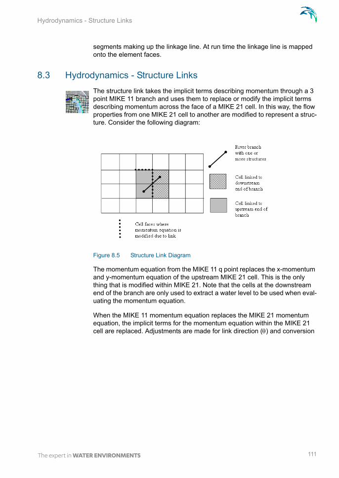
Hydrodynamics - Structure Links
segments making up the linkage line. At run time the linkage line is mapped onto the element faces.
8.3 Hydrodynamics - Structure Links
The structure link takes the implicit terms describing momentum through a 3 point MIKE 11 branch and uses them to replace or modify the implicit terms describing momentum across the face of a MIKE 21 cell. In this way, the flow properties from one MIKE 21 cell to another are modified to represent a struc-ture. Consider the following diagram:
Figure 8.5 Structure Link Diagram
The momentum equation from the MIKE 11 q point replaces the x-momentum and y-momentum equation of the upstream MIKE 21 cell. This is the only thing that is modified within MIKE 21. Note that the cells at the downstream end of the branch are only used to extract a water level to be used when eval-uating the momentum equation.
When the MIKE 11 momentum equation replaces the MIKE 21 momentum equation, the implicit terms for the momentum equation within the MIKE 21 cell are replaced. Adjustments are made for link direction () and conversion
111

Scientific Background
from discharge (Q) to flux (q = Q/D, D = 2D cell size). For the momentum equation in the x direction:
(8.2)
(8.3)
(8.4)
(8.5)
(8.6)
If the terms are added (for example if the structure link represents a structure flowing under the existing MIKE 21 topography), further adjustments are made to ensure consistency between the MIKE 11 and MIKE 21 terms. Again for the x direction:
(8.7)
(8.8)
(8.9)
(8.10)
(8.11)
The same adjustments apply for the y direction momentum equation, except a sine direction adjustment is made rather than a cosine adjustment.
Note that the implicit terms from MIKE 11 used are from the MIKE 11 solution at the previous time step. In most applications, where flow conditions vary quite slowly relative to the time step, this is not a problem. It may become a problem if rapid (and relevant) changes do occur over a time step. Also, the displayed value of flow in the q point of the MIKE 11 branch may not neces-
aM21hj 1+n 1+ bM21qj 1+
n 1+ cM21hj 1–n 1+ dM21=+ +
aM21aM21 cos
------------------------=
bM21 bM11=
cM21cM21 cos
-----------------------=
dM21dM21 cos
------------------------=
aM21hj 1+n 1+ bM21qj 1+
n 1+ cM21hj 1–n 1+ dM21=+ +
aM21* aM21
aM11bM21 cos
bM11-----------------------------------+=
bM21 bM11=
cM21* cM21
cM11bM21 cos
bM11-----------------------------------+=
dM21* dM21
dM11bM21 cos
bM11-----------------------------------+=
112 MIKE FLOOD - © DHI

Hydrodynamics - Zero Flow Links
sarily be the flow through the MIKE 21 cell. It is recommended that the MIKE 21 results are interrogated in this case rather than the MIKE 11 results.
8.3.1 Hydrodynamics - Exponential smoothing factor
The exponential smoothing factor may be used for links which are misbehav-ing causing oscillations. Though note that the smoothing factor will cause a time lag in the corresponding water levels between the coupled models. The exponential smoothing factor works by applying a weight to the transferred water level from MIKE 21 to MIKE 11. The expression reads
(8.12)
where is the smoothing factor, HM11 is the MIKE 11 water level, HM21 the MIKE 21 water level and n is the time step. By applying this expression n times the water level may be given as
(8.13)
Using the above expression a criteria for selection of the smoothing factor may be obtained. Assuming that the water level in MIKE 21 is constant then the number of time steps n it will take the MIKE 11 water level to be within a fraction f of the MIKE 21 water level is given by
(8.14)
Thus the smoothing factor should be chosen in relation to the time scale at which the dynamics change in the model.
8.4 Hydrodynamics - Zero Flow Links
If the link type is a XFLOW = 0 link, the x direction momentum across the right face of the MIKE 21 cell is set so that p= 0. This is done by modifying the implicit terms:
(8.15)
(8.16)
(8.17)
HM11 n 1 – HM11 n 1– HM21 n +=
HM11 n 1 – nHM11 0 1 – iHM21 n i–
i 0=
n
+=
n flog1 – log
-------------------------=
aM21hj 1+n 1+ bM21qj 1+
n 1+ cM21hj 1–n 1+ dM21=+ +
aM21 cM21 dM21 0= = =
bM21 1=
113
Scientific Background
Similarly, if a YFLOW = 0 link, the y direction momentum across the top face of the MIKE 21 cell is set to q = 0.
8.5 Hydrodynamics - Urban links
The exchange of water (QUM21) at the inlet can be computed in three different ways:
Orifice equation
Weir equation
Exponential function
The orifice calculation is given by:
(8.18)
for |QUM21|< Qmax , where
QUM21: Flow from sewer to MIKE 21 grid point.HU Water level in sewer system.HM21: The average water level on the ground.Am: Cross-sectional area of manhole.AI: Cross-sectional area of inlet (not used for basins) andCD The discharge coefficient (typically 1).
Note that if the nodes ground level is greater than either the water level in the node or the water level in MIKE 21 then the corresponding water level is over-ridden by the ground level.
The weir equation depends on whether there is flooding on the surface or not. If the surface is not flooded at the time, then it is calculated as a free flowing weir:
(8.19)
for |QUM21|< Qmax, where Wcrest is crest width to be used in the equation and CD is the discharge coefficient. The same equation is used if surface is flooded and the water level in the node is below the nodes ground level.
If the surface is flooded (water level in MIKE 21 and MIKE URBAN above the nodes ground level) then the weir is calculated as a submerged weir:
(8.20)
The term is Hg is the ground level at the coupling.
QUM21 sign HU HM21– CDMin Am AI 2g HU HM21–=
QUM21 C HU HM21– Wcrest 2g HU HM21–=
QUM21 C HU HM21– Wcrest 2g HU HM21–HU HM21–
max HM21 HU Hg–--------------------------------------------------- =
114 MIKE FLOOD - © DHI
Urban River Links
The last function for computing the flow between MIKE URBAN(MOUSE) and MIKE 21 is given by:
(8.21)
for |QUM21|< Qmax , where S is the Scaling factor and Exp the Exponent.
Note that in eq. (8.21) the values of H are given in meters and the discharge is given in m3/s.
There is an option to suppress oscillations by use of the QdH factor. The value corresponds to the water level difference below which the suppression is applied. The suppression is designed for cases where the pressure level in the sewer system is close to the water level in MIKE 21 and may be applied individually at each urban coupling. If a value of 0.0 is given then no suppres-sion is applied. When another QdH value is given, the discharge from equa-tion (8.21) is multiplied by a suppression factor between 0 and 1. When the water level difference between the node and MIKE 21 is greater than Qdh then the factor is 1. For water level differences dh less than QdH, the sup-pression factor is:
(8.22)
8.6 Urban River Links
Basically the urban river links may be of two types:
two way couplings
one way couplings
The former is used by the water level boundary in MIKE 11 coupling and the outlet coupling. The mechanism is that one model delivers a water level and in return receives a discharge.
The second type of coupling does not have feedback mechanism (weirs and pumps) so these simply act as source terms in MIKE 11.
8.7 Advection-Dispersion
Concentrations of AD components are transferred explicitly between MIKE 11 and MIKE 21 depending on the direction of the flow. For standard links with flow from MIKE 11 to MIKE 21, the concentration of the AD-component is imposed as with a standard MIKE 21 source, i.e. as a flux of mass into the
QUM21 sign HU HM21– S max HM21 Hg max HU Hg – Exp=
Suppressionfactor 1 QdH dh– QdH 2–=
115
Scientific Background
MIKE 21points:
(8.23)
When flow is going from MIKE 21 to MIKE 11, the modification to the AD-equation in MIKE 21 is:
(8.24)
The corresponding boundary condition in MIKE 11 can be either a transport boundary or a concentration boundary as usual. Furthermore, a mixing coeffi-cient can be defined as normal. It is strongly recommended to use a transport boundary condition in MIKE 11.
For lateral links, the mass of the AD component being transferred is calcu-lated from the lateral discharge and the concentration in MIKE 11 or MIKE 21 (depending upon flow direction). This is then applied as a source or sink term in the branches and cells. The source term into MIKE 21 is as for the stand-ard links. For MIKE 11, the one dimensional advection dispersion equation is:
(8.25)
where C is concentration, D dispersion coefficient, A cross-sectional area, K linear decay, C2 the source/sink concentration and q lateral inflow per river length.
For zero flow links, no advection will occur across the link due to the zero flow specification, and dispersion is turned off.
8.8 Flow Distribution by Depth
Flow is distributed according to the Chezy equation for resistance:
(8.26)
where:
Q = Flow;A = Area (= width · depth = w · h);C = Chezy coefficient;R = Hydraulic radius (approx. = depth = h); andS = slope.
V CM21
n ½+t
-------------------------- Qn ½+ CM11
n=
V CM21
n ½+t
-------------------------- Qn ½+ CM21
n=
ACt
------------ QCx
------------x------ AD
Cx-------
AKC– C2q+=–+
Q AC RS=
116 MIKE FLOOD - © DHI

Inclusion of Friction Term in Weir Formulae 1 and 2 (Honma)
Rearranging this equation gives:
(8.27)
Thus, proportionality can be derived between flow and water depth (h):
(8.28)
Flow is then distributed across a number (n) of MIKE 21 cells. For each cell (count i = 1...n), the distributed flow Qi is calculated from the total flow QTOT:
(8.29)
8.9 Inclusion of Friction Term in Weir Formulae 1 and 2 (Honma)
The equation for the Weir Formula 1 is:
(8.30)
where w = width, C = weir coefficient, k = exponential coefficient (1.5), h1 = depth of water above weir level upstream (Hus - Hw) and h2 = depth of water above weir level downstream (Hds - Hw). This equation is actually a free over-flow term (wChk) combined with a scaling term for submergence ([...]0.385) that approaches 0 as h1 approaches h2. The equation for the Weir Formula 2 (Honma) is:
(8.31)
The first equation is free overflow (identical to Formula 1 with free overflow), while the second is for submerged conditions.
Both equations are derived from the equation for form loss across a structure, where
(8.32)
Q whCh0.5S0.5 h1.5wCS0.5= =
Q h1.5
Qi QTOT
hi1.5
hi1.5
i 1=
n
-----------------=
Q wCh1k 1
h2
h1
-----
k
–0.385
=
Q wCh1 h1= forh2
h1
----- 2 3 :
Q w32--- 3Ch2 h1 h2–= for
h2
h1
----- 2 3 :
h v2
2g------=
117

Scientific Background
If a friction loss is added this becomes:
(8.33)
where:
(8.34)
L = length of structure,n = Manning’s number.
L is calculated as length between opposite corners in a MIKE 21 grid cell (= the hypot-
enuse) : (8.35)
Expanding:
(8.36)
This equation is similar in form to Weir Formulae 1 and 2 for free overflow, except that the weir coefficient is replaced:
(8.37)
Assuming that the entrance and exit losses are identical, a new weir coeffi-cient Cf can be derived from the original coefficient C and the additional fric-tion:
(8.38)
(8.39)
h F+ v2
2g------=
F 2gLn2
h14 3
----------------=
L XM21 2 YM21 2+ =
Q w 2g F+
-----------------h1 h=
C 2g F+-------------=
C 2g
------ <=> 2g
C2------==
Cf2g F+------------- 2g
2g C2 F+---------------------------= =
118 MIKE FLOOD - © DHI

Inclusion of Friction Term in Weir Formulae 1 and 2 (Honma)
So, the existing equations for weir flow calculations can be used, except that the weir coefficient is modified according to:
(8.40)
This equation is applied to the weir calculations in the lateral link specifica-tions.
Cf2g
2g C2 2gLn2
h14 3
----------------+
----------------------------------------=
119

Scientific Background
120 MIKE FLOOD - © DHI

Standing Wave
9 Examples
The examples presented below are designed to test the operation of the fea-tures of MIKE FLOOD and to demonstrate the use of these features. Most are available with the DHI software in the “Examples” folder. Otherwise, check www.mikebydhi.com, where the input files can be downloaded.
Various MIKE ZERO tools can be used to view the results, including the Result Viewer, MIKE VIEW (not in MIKE ZERO), Plot Composer, and the time series, profile series and grid series editors.
A brief outline of the examples is provided:
Standing Wave: examines momentum transfer through standard links
Lateral Link 1: investigates lateral link flow over a bank of varying bed levels and includes an AD component
Lateral Link 1: investigates lateral link flow and compares results to a standard MIKE 11 weir
Flow Direction: examines flow directions through various links
Flood plain Flow: examines the transition from in-bank to flood plain flow in a simplified setup
Floodplain Demonstration: demonstration of a real flood plain applica-tion. The example is available both for the rectangular case as well as the flexible mesh version.
2 urban flooding examples are included: Urban and Waterville. They investigate the different urban links available between MIKE URBAN and MIKE 21.
MIKE FLOOD 3way: a 3-way coupling example with MIKE 11, MIKE URBAN and MIKE 21 (both rectangular and flexible mesh versions).
9.1 Standing Wave
Consider an 8 km long basin closed at both ends:
Figure 9.1 Standing Wave Test Layout
121

Examples
The width of the basin is 100 m and the mean water depth is 2.0 m. The bed resistance is C = 50 m1/2/s. An initial disturbance of the water surface is imposed corresponding to a sinusoidal variation of range 0.10 m.
The basin is described using MIKE FLOOD. 4 km is described in MIKE 11, and 4 km is described in MIKE 21. In both models, the longitudinal grid spac-ing is 100 m. MIKE FLOOD simulates the transfer of mass as well as momen-tum between the 1D MIKE 11 model and the 2D MIKE 21 model. The water level at different times after start of the simulation is depicted below.
Figure 9.2 Standing Wave Test Results - Water Level Profiles
The files required to setup and run this example are available. These files take this example further than presented here, with tests using:
the standard link type;
a 10 cell / 1000 m wide setup of the same test case;
a MIKE 11 model of the entire test (no MIKE FLOOD link); and
a MIKE 21 model of the entire test (no MIKE FLOOD link).
Thus, four separate tests are included in this single MIKE FLOOD setup. The results are shown as water level profiles at various time steps:
122 MIKE FLOOD - © DHI
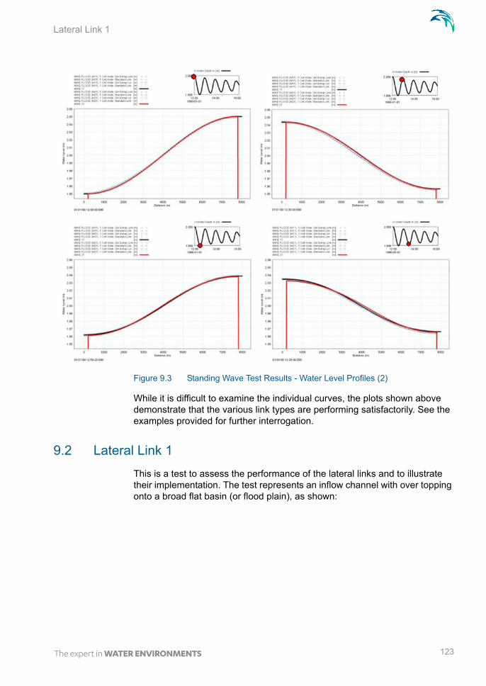
Lateral Link 1
Figure 9.3 Standing Wave Test Results - Water Level Profiles (2)
While it is difficult to examine the individual curves, the plots shown above demonstrate that the various link types are performing satisfactorily. See the examples provided for further interrogation.
9.2 Lateral Link 1
This is a test to assess the performance of the lateral links and to illustrate their implementation. The test represents an inflow channel with over topping onto a broad flat basin (or flood plain), as shown:
123
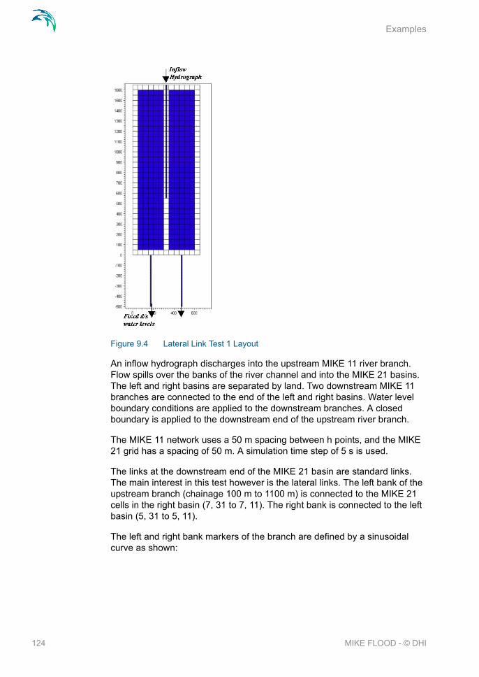
Examples
Figure 9.4 Lateral Link Test 1 Layout
An inflow hydrograph discharges into the upstream MIKE 11 river branch. Flow spills over the banks of the river channel and into the MIKE 21 basins. The left and right basins are separated by land. Two downstream MIKE 11 branches are connected to the end of the left and right basins. Water level boundary conditions are applied to the downstream branches. A closed boundary is applied to the downstream end of the upstream river branch.
The MIKE 11 network uses a 50 m spacing between h points, and the MIKE 21 grid has a spacing of 50 m. A simulation time step of 5 s is used.
The links at the downstream end of the MIKE 21 basin are standard links. The main interest in this test however is the lateral links. The left bank of the upstream branch (chainage 100 m to 1100 m) is connected to the MIKE 21 cells in the right basin (7, 31 to 7, 11). The right bank is connected to the left basin (5, 31 to 5, 11).
The left and right bank markers of the branch are defined by a sinusoidal curve as shown:
124 MIKE FLOOD - © DHI
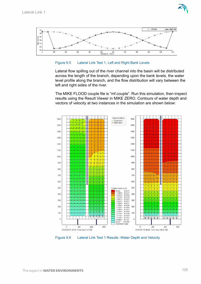
Lateral Link 1
Figure 9.5 Lateral Link Test 1, Left and Right Bank Levels
Lateral flow spilling out of the river channel into the basin will be distributed across the length of the branch, depending upon the bank levels, the water level profile along the branch, and the flow distribution will vary between the left and right sides of the river.
The MIKE FLOOD couple file is “mf.couple”. Run this simulation, then inspect results using the Result Viewer in MIKE ZERO. Contours of water depth and vectors of velocity at two instances in the simulation are shown below:
Figure 9.6 Lateral Link Test 1 Results -Water Depth and Velocity
125

Examples
There is a distinct difference in flow patterns between the left and right basins. Using MIKE VIEW, look at the longitudinal profile of the upstream branch:
Figure 9.7 Lateral Link Test 1 Results -Water Level and Flow Profile
Similarly, the lateral discharges can also be presented (tick the “Lateral Inflows” button in the Additional Output Menu in HD Parameters):
Figure 9.8 Lateral Link Test 1 Results - Lateral Flow Profile
Last (but not least), a check of the mass in the system can be made by com-paring the total discharge into the model (the upstream inflow from the upstream branch) with the discharge out of the model (from the downstream branches):
As shown, 100 m3/s enters from upstream. The flows are distributed so that 47.76 m3/s flows through the left branch and 52.24 m3/s through the right.
126 MIKE FLOOD - © DHI

Lateral Link 1
Figure 9.9 Lateral Link Test 1 Results -Time Series of Discharge
For comparison, the same setup has been done using MIKE 11. For the MIKE 11 setup, the left and right basins are represented using branches. Flow from the upstream branch to the basins occurs through two additional branches with cross-sections representing the bank levels. The MIKE 11 test has been combined with the original MIKE FLOOD application (see mf2.couple):
Figure 9.10 Lateral Link Test 1 Layout (2)
The MIKE 11 test has two branches representing lateral flow aligned equally at the centre of the upstream branch. Comparison of discharges from the
127

Examples
downstream branches for the MIKE FLOOD and MIKE 11 tests are presented below:
Figure 9.11 Lateral Link Test 1 Results - Time Series of Discharge (2)
Both the MIKE FLOOD and MIKE 11 simulations preserve mass, with the amount of flow leaving the system exactly the same as the amount entering. However, the MIKE FLOOD and MIKE 11 simulations each give different dis-tributions between the left and right banks. There are several possible rea-sons for this:
MIKE FLOOD accounts for the water level gradient in the channel. This increases the accuracy of over bank flow calculations.
MIKE FLOOD calculates weir flow across each calculation point (20 in total), whereas the MIKE 11 simulation calculates weir flow at one calcu-lation point.
It is possible that additional losses from 2D effects (such as eddy forma-tions) in MIKE 21 are contributing to the lateral link structure losses. This may create a variation between a MIKE 11 prediction and the MIKE FLOOD prediction.
The findings of this test show that the lateral links are mass preserving and behave as expected. Further, the test highlights the importance of using lat-eral links in situations where there is a significant water level gradient in the in-bank river channel.
Finally, an AD simulation is added to the test. To do this, add the AD compu-tation to MIKE 11 and MIKE 21, then set the MIKE FLOOD Coupling Type to be “HD and AD”.
The time series plot displays pollutant concentrations entering the upstream boundary and flowing out the two downstream boundaries:
128 MIKE FLOOD - © DHI

Lateral Link 2
Figure 9.12 Lateral Link Test 1 Results - Time Series of Concentration
Also, contour plots of concentration in the MIKE 21 domain are shown at two instances:
Figure 9.13 Lateral Link Test 1 Results - Concentration
9.3 Lateral Link 2
This is a test to ensure that the structure equation in the lateral link is consist-ent with that in a standard MIKE 11 simulation. The first test is a simple MIKE
129

Examples
FLOOD model that has a MIKE 11 branch linked to a MIKE 21 basin using a standard link:
Figure 9.14 Lateral Link Test 2 - Standard Link Layout
The MIKE 11 branch is 1000 m long with a uniform cross-section of width 500 and bed level 0 m. The MIKE 21 basin is also 500 m wide with a bed level of 0 m, and is 1000 m long. Grid spacing is 100 m. The MIKE 11 branch has a weir located near the link (chainage 850 m). This weir has a height of 2.2 m and is 500 m wide. A weir formula 1 is applied.
The second test aims to replicate the first, except using a lateral link rather than a standard link. The MIKE 11 branch (branch1) is the same as the first test except it is truncated at the weir location (at chainage 800 m) where another branch (latb) is attached. This branch has a length of 500 m, and the left banks of the cross-sections have a bed level of 2.2 m. The lateral link con-nects this branch to the MIKE 21 basin. A weir formula 1 is applied in the lat-eral link.
Figure 9.15 Lateral Link Test 2 - Lateral Link Layout
The initial water level and the downstream water level at the MIKE 21 bound-ary is 2 m (so water depth is 2 m in the upstream branch and in the MIKE 21 grid). The simulations are performed using a time step of 30 s (explicit Cou-rant conditions). The upstream flow boundary in MIKE 11 gradually rises from 0 m3/s to 100 m3/s and remains steady at this flow rate.
The resulting water level at the upstream end of the MIKE 11 branch and the discharge at the downstream end are presented below:
130 MIKE FLOOD - © DHI

Lateral Link 2
Figure 9.16 Lateral Link Test 2 Results - Time Series of Water Level
Figure 9.17 Lateral Link Test 2 Results - Time Series of Discharge
There is a slight variation in water levels as the discharge increases, but the steady state levels are similar for both simulations (2.43 m and 2.44 m). These variations may be due to the missing momentum transfer across the lateral links. Steady state discharge is the same for both simulations (100 m3/s), indicating that mass is conserved through the links. Notice the oscilla-tions in the discharge at the downstream end of the MIKE 21 basin. This is a result of reflections in the MIKE 21 model, created as the initial wave front produced by the rising discharge enters the MIKE 21 domain.
The water level contours and current vectors in MIKE 21 for each simulation are presented below. Notice that there is a slight variation in flow distributions in the laterally linked case (the variations are shown by the velocity vectors in the link cells).
131

Examples
Figure 9.18 Lateral Link Test 2 Results - Standard Link
Figure 9.19 Lateral Link Test 2 Results - Lateral Link
9.4 Flow Direction
This test was initially designed to test links applied in a direction that is not aligned with the MIKE 21 grid. However, it evolved into a demonstration of all the link types available in MIKE FLOOD.
The test consists of a square MIKE 21 basin with a variety of MIKE 11 branches discharging flow into it. The branches are aligned at different angles to the MIKE 21 grid, and consist of standard and lateral links. In the centre of the basin is a lateral link that drains the basin. Using the zero flow links, the bottom right corner has been isolated from the rest of the basin, except for two structure links on each side. The structure links are connected to 3 point MIKE 11 branches with a weir. Some of the link cells in MIKE 21 are com-pletely surrounded by wet cells. Others have land cells, or alternatively zero flow links, inserted behind the link cells.
The MIKE 21 grid size is 10 m and the initial water level is 1 m. A constant discharge of 10 m3/s is applied to the upstream end of each branch, and the time step in both MIKE 11 and MIKE 21 is 2 s.
132 MIKE FLOOD - © DHI

Flow Direction
Figure 9.20 Flow Direction Test Layout
The HD simulation, run to steady state conditions, is presented below:
133

Examples
Figure 9.21 Flow Direction Test Results - Water Depth and Velocity
As shown, the direction of flow discharging from each linkage point is consist-ent with the branch alignment. The link points that have land or zero flow links behind them show slightly different flow patterns. As a result of the zero flow links, water levels in the bottom right corner are lower than the rest of the model. This is driving flow through the structure links.
An AD simulation was also performed. Initial concentration was set to zero and inflows apply a conservative concentration of 100. The contour plot below shows results:
134 MIKE FLOOD - © DHI

Flow Direction
Figure 9.22 Flow Direction Test Results - Concentration
The flow directions from the links create a slight “whirlpool” pattern. The zero flow links are also zero concentration links - the plot above demonstrates that the zero flow links are a barrier to advection and dispersion.
Finally, a check of mass conservation in the model is made. With 8 separate inflow branches the total flow rate into the system is 80 m3/s. The resulting discharge through the draining lateral link in the centre of the basin is shown below. At the completion of the simulation, the flow rate shown in MIKE VIEW at the last point in the lateral flow branch is 77 m3/s. While this may appear to be a mass loss error, in fact it is a minor presentation bug caused by having a lateral link at the last h point in the branch. The discharge presented in MIKE VIEW is at the last q point. As lateral flows are added to the h points, this means that the flow rate of 77 m3/s does not include an additional 3 m3/s entering the last h point.
To check this, rerun this simulation with the lateral link connected between chainage 20 to 100 m on the MIKE 11 branch (branch9). The discharge at the last point will then be presented as 80 m3/s, indicating that mass is pre-served.
135

Examples
9.5 Flood plain Flow
This is another test of the lateral links. It compares model performance over a broad flood plain application. This is a simplified representation of a typical lateral link application - flood plain in MIKE 21, river channel in MIKE 11, and flow between them in MIKE FLOOD.
The test consists of four separate setups:
MIKE FLOOD -river channel modelled in MIKE 11, footplates in MIKE 21, connected with MIKE FLOOD lateral links (“mf.couple”)
MIKE 11 - single branch for main channel and footplates (“mf.couple”)
MIKE 11 - separate main channel and flood plain branches, intercon-nected by link channels (“mf.couple”)
MIKE 21 - both river channel and floodplains modelled in MIKE 21 (“m21a.M21”)
Figure 9.23 Floodplain Flow Test Layout
136 MIKE FLOOD - © DHI

Flood plain Flow
Each test represents the same geometry, consisting of a 50 m wide, 5 m deep channel. On each side of the channel is a 50 m wide levee. Beyond the levees the floodplains are initially 1 m below the levees, and rise laterally by 1 m over a distance of 250 m. A typical cross-section is shown:
Figure 9.24 Floodplain Flow Test - Typical Cross-section
The total length is 10000 m. The river has a uniform slope of 1:1000 - the bed of the main river channel upstream is 10 m, and the bed downstream is 0 m.
To each of these setups, an upstream flow hydrograph is applied, which has a peak discharge of 2000 m3/s. A downstream water depth of 4 m is main-tained.
Figure 9.25 Floodplain Flow Test - Upstream Hydrograph
The water level at the upstream end of each of the four models is presented:
Figure 9.26 Floodplain Flow Test Results - Upstream Water Level
Further, the discharge at the downstream ends of each model is presented with the upstream hydrograph:
137

Examples
Figure 9.27 Floodplain Flow Test Results - Downstream Discharge
For each test case the upstream water levels are reasonably consistent with the other. However, the MIKE 21 simulation predicts a higher water level, suggesting more losses along the length of the model. The downstream dis-charges are also reasonably consistent, although again the MIKE 21 simula-tion (and to a lesser extent the MIKE FLOOD simulation) have a reduced, more dampened discharge peak. This again suggests more losses in the model.
A possible reason for this variation in model predictions between MIKE 11 and MIKE 21 could be due to wetting and drying in MIKE 21.
9.6 Floodplain Demonstration
This example is available as a demonstration model to illustrate a real appli-cation of MIKE FLOOD using the rectangular grid. The application consists of a flood simulation through a river system. The area of interest is at a conflu-ence with a tributary, where a road embankment has been proposed. Cul-verts under the road are located on each side of the river.
The river system is represented in MIKE 11. A MIKE 21 grid is inserted into the broader MIKE 11 network to represent flood plain flow, as shown in Figure 9.28:
138 MIKE FLOOD - © DHI

Floodplain Demonstration
Figure 9.28 Floodplain Demonstration Layout
A 5 s time step is used in the simulation and the MIKE 21 grid size is 30 m. The model has been developed with the following MIKE FLOOD links:
lateral links between the main river channel and floodplain and the tribu-tary and floodplain
zero flow links along the centre line of the river channel, to ensure that water flows from one side of the floodplain to the other via the main channel
similarly, zero flow links along the centre line of the tributary
zero flow links defining the road embankment (assuming that the road does not over top)
implicit structure links for flow through the culverts
A diagram illustrating the locations of the links is shown:
139

Examples
Figure 9.29 Floodplain Demonstration, Diagram of MIKE FLOOD Links
The upstream discharge hydrographs for the river and tributary and the downstream water level boundary condition (which is tidal), are shown below:
Figure 9.30 Floodplain Demonstration Boundary Conditions
Model results showing water surface contours and velocity vectors near the peak of the flood event are presented in Figure 40. The time series plots in Figure 9.32 show water levels immediately upstream and downstream of the road embankment, and water level difference across the road embankment.
140 MIKE FLOOD - © DHI

Floodplain Demonstration
Also shown is discharge through the main river channel and through each culvert.
The model results show that for this particular flood event there is a peak 0.36 m head drop across the road embankment. However, the peak head drop at the peak of the flood is 0.16 m. Peak discharge through the main river chan-nel is 44.2 m3/s, which is much higher than the culvert flows of (1.7 m3/s and 3.8 m3/s).
If this model was intended to investigate the hydraulic impacts of the road embankment, a model of the existing situation (no road) could also be per-formed. Comparing model results with and without the road embankment could give an indication of the likely impacts. Also, the performance of the cul-verts could be assessed (maybe more are needed?).
Note that this is a demonstration model - not a real example. Other modelling considerations that could be of relevance in this example include:
The MIKE 21 grid does not cover the entire floodplain width.
The proposed road crosses over the main channel. Any hydraulic effects (bridge structure or pier losses) created by this situation are ignored.
The roughness parameter on the floodplain has been set to a constant value of M=20. The roughness may actually be varying spatially, particu-larly if there are a range of land use patterns.
The upstream and downstream MIKE 11 branches only represent the main channel. They do not include the flood plains.
The flood plain example is also available as a flexible mesh version. Note that the flexible mesh version does not have zero-flow links available since these may easily be accomplished through the use of internal closed boundaries. The latter has also been done for the flood plain example to model the road cutting through the flood plain.
141

Examples
Figure 9.31 Floodplain Demonstration, Water Surface and Velocities near peak of flood
Figure 9.32 Flood plain Demonstration Results - Water Levels and Flows at Road Embankment
142 MIKE FLOOD - © DHI

Urban examples
9.7 Urban examples
Two urban examples are also included with the installation: Urban and Water-ville.
9.7.1 Urban
The first of these urban examples (Urban) is based on an area in Bangkok and is a reduced model from the full model. The present model represents a sub set of the sewer network and further only couples the 2D and the 1D sewer model at four locations (see Figure 9.33). More links between the 1D and 2D models can be added using the right-click option on the graphical view and choosing “Link urban node to MIKE 21”. You could for example link an urban outlet to MIKE 21 or more manholes to MIKE 21. You need to pre-process the MIKE URBAN setup (Run > MIKE URBAN Preprocessing) before you can run the MIKE FLOOD simulation.
The set-up files are located in the folder
.\MIKE Zero\Examples\MIKE_FLOOD\Urban
The example mimics a storm event that results in the sewer system being surcharged causing inundation on the streets. The main buildings have been included in the bathymetry and appear in green on the image below.
Figure 9.33 The grid with the sewer system shown in pink
9.7.2 Waterville
Waterville is a small urban setup that couples several manholes to a 2D sur-face.
143

Examples
Figure 9.34 The sewer system in green and yellow, the urban bathymetry with some buildings represented in green and the couples manholes in red and white
9.8 MIKE FLOOD 3way
The MIKE FLOOD 3way example is an integrated flood model that includes a river channel, the storm water system and the surface of a city. It is the demonstration of a real flood modelling application of a 100 year flood event.
The model integrates:
A river channel in MIKE 11
A storm water piped network in MIKE URBAN
A surface for 2D overland flow in MIKE 21. The example is available for the rectangular version as well as the flexible mesh version.
All aspects of flow interactions are taken into account through the different links applied:
144 MIKE FLOOD - © DHI
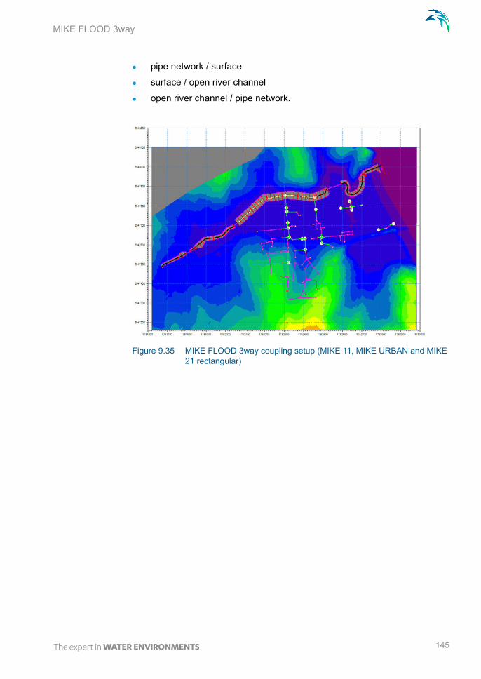
MIKE FLOOD 3way
pipe network / surface
surface / open river channel
open river channel / pipe network.
Figure 9.35 MIKE FLOOD 3way coupling setup (MIKE 11, MIKE URBAN and MIKE 21 rectangular)
145

Examples
Figure 9.36 MIKE FLOOD 3way coupling setup (MIKE 11, MIKE URBAN and MIKE 21 FM)
Note that the original data have been modified (hydrology, river geometry and structures, storm water system, topography) so the model and the results do not represent the reality.
The first step in building this MIKE FLOOD 3way example consisted in build-ing and running the individual models: MIKE 11, MIKE URBAN and MIKE 21.
The hydrology is distributed in MIKE 11 and MIKE URBAN. Rainfall-runoff models have been run prior to this example and only the results are used as inflow boundary to the hydrodynamic simulation.
Once the individual models were fully stable and ran successfully, the MIKE FLOOD model was developed and links between the 3 models defined.
The order in which the links are defined is not important; you could start with the River/Urban links for example, then continue with the Urban links and finally define the River links. It is recommended that you check that the MIKE FLOOD model is running successfully once you have defined links and before you add another type of links. In this way it is easier to spot any errors with the links.
9.8.1 River links between MIKE 11 and MIKE 21
The MIKE 11 setup includes one river channel with several culvert and weir structures. The river was coupled to the floodplain using several lateral links and one standard link.
146 MIKE FLOOD - © DHI

MIKE FLOOD 3way
The river was linked laterally to MIKE 21 to represent spilling from the river to the floodplain and drainage back into the river. The left and the right banks of the channel were coupled to MIKE 21. Lateral links were discontinued where the river flows through long culverts.
Note that the extent of the river channel was removed from the bathymetry in order to avoid double conveyance. For MIKE 21 rectangular, the river cells were raised to the land value in the bathymetry using the "Block river cell fea-ture in MIKE FLOOD" (see description page 60). For MIKE 21 FM, the river was excluded from the flexible mesh using the MIKE11_curve.xyz file as a boundary in the Mesh Generator (see MIKE 21 flexible mesh (p. 97)).
A standard link couples the end of the MIKE 11 branch to the sea in MIKE 21.
Figure 9.37 River links between MIKE 11 and MIKE 21
9.8.2 Urban links between MIKE URBAN and MIKE 21
The storm water system of the city has 115 manholes and 3 outlets. One out-let is discharging into the sea and the 2 others are discharging into the river. Runoff inflow from catchments is distributed to all nodes. During the 100 year rain event, the storm water system is surcharged and overflows on the sur-face causing flooding.
147

Examples
18 urban links were defined between MIKE URBAN and MIKE 21: 17 "M21 to inlet" links to couple manholes to the surface and one "M21 to outlet" link for the outlet to the sea.
Figure 9.38 Urban Links between MIKE URBAN and MIKE 21
Remember that you need to preprocess the MIKE URBAN setup before you can run the MIKE FLOOD simulation.
9.8.3 River/Urban links between MIKE URBAN and MIKE 11
The storm water system is discharging into the river at 4 different locations so 4 River/Urban links were specified between MIKE 11 and MIKE URBAN:
1 MIKE URBAN weir to MIKE 11
1 MIKE URBAN pump to MIKE 11
2 MIKE URBAN outlets to MIKE 11.
148 MIKE FLOOD - © DHI

MIKE FLOOD 3way
Figure 9.39 River/Urban links between MIKE 11 and MIKE URBAN
The results of the maximum water depth for the 100 year rainfall event are presented below.
Figure 9.40 Maximum water depth during the 100 year rainfall event
149

Examples
150 MIKE FLOOD - © DHI

INDEX
151

Index
AActivation Depth . . . . . . . . . . . . 69AD components . . . . . . . . . . . . . 85Add/Remove Images . . . . . . . . . . 54Add/Remove Layers . . . . . . . . . . 46Add/Replace Momentum Terms . . . . 68Advection Dispersion . . . . . . . . . . 96
CChange existing Link values . . . . . . 28
DDefault Value for Land . . . . . . . . . 96Default values . . . . . . . . . . . . . 25DELTA parameter . . . . . . . . . 95, 99Depth Adjustment . . . . . . . . . . . . 68Depth Tolerance . . . . . . . . . . . . 74
EExplicit Links . . . . . . . . . . . . . . 99Export Links to Selection File . . . . . . 64Ext Fact . . . . . . . . . . . . . . . . . 67External Files . . . . . . . . . . . . . . 75
GGraphical View . . . . . . . . . . . . . 41
HHydrodynamics . . . . . . . . . . . . . 105
LLateral Link Height . . . . . . . . . . . 76Lateral Links . . . . . . . .16, 37, 99, 100Link Parameters - Global link settings . 24Link Type . . . . . . . . . . . . . . . . 37Linkage Types . . . . . . . . . . . . . 55
MMFLateral . . . . . . . . . . . . . . . . 77MIKE 21 . . . . . . . . . . . . . . . . 32MIKE 21 Area Number . . . . . . . . . 38MIKE 21 Cell indices . . . . . . . . . . 39MIKE 21 Coordinates . . . . . . . . . . 38MIKE Flood Editor . . . . . . . . . 23, 85MIKE Flood Editor, AD components . . 85MIKE Flood Editor, Lateral Links . . . . 71MIKE Flood Editor, Link Definitions . . . 34MIKE Flood Editor, Linkage Files . . . . 32
MIKE Flood Editor, River-Urban Links . .82MIKE Flood Editor, Side Structure Links .84MIKE Flood Editor, Standard/Structure
Links . . . . . . . . . . . . . . . . . .66MIKE Flood Editor, Urban Links . . . . .79MIKE11_curve.xyz . . . . . . . . . . . .97Model Layout . . . . . . . . . . . . . . .89Model Linkages . . . . . . . . . . . . .15Mom Fact . . . . . . . . . . . . . . . . .67
NNuber of Segments . . . . . . . . . . . .57
PPre and Post Processing . . . . . . . . .91
RResult Viewer . . . . . . . . . . . . . .91river name . . . . . . . . . . . . . . . .37
SScientific Background . . . . . . . . . 105Seamless 1D and 2D Results . . . . . .87Side of River . . . . . . . . . . . . . . .72Simulation Results . . . . . . . . . . . .87Smagorinsky Eddy Viscosity . . . . . . .96Stability . . . . . . . . . . . . . . . . . .98Standard Links . . . . . . . . . . . .15, 99Structure . . . . . . . . . . . . 72, 73, 74Structure Links . . . . . . . . . . . 17, 102
TTable editing toolbar . . . . . . . . . . .36Tips and Troubleshooting . . . . . . . .95
ZZero Flow . . . . . . . . . . . . 19, 38, 103
152 MIKE FLOOD - © DHI
Copyright © 2022 FDOKUMEN