Microfluidic production of ultrasound contrast agents with a capillary gas jet PDMS microchip
8
Microfluidic production of ultrasound contrast agents with a capillary gas jet PDMS microchip Chuanpin Chen a , Patrick W. Leech b , Yonggang Zhu* a , Richard Manasseh a a CSIRO Materials Science and Engineering, PO Box 56, Highett, VIC 3190, Australia b CSIRO Materials Science and Engineering, Gate 5, Normanby Road, Clayton, VIC 3168, Australia ABSTRACT Microbubbles have been used as ultrasound contrast agents in medical applications such as imaging, and also for drug/gene delivery, target destruction and so on. Microbubbles are normally made by sonication techniques and the resulting size distribution is very large. Microfluidics provides an alternative way of microbubble fabrication due to recent advances in microfabrication and microfluidics development. The current techniques are capable of making bubbles with a size of several micrometers. However, the throughput for such a size range is very limited. In this study, a new microfluidic bubble generation chip was developed, which incorporates a T-junction PDMS microchannel network with an inserted glass capillary. The flow rate of liquid, gas pressure and the inserted capillary inner diameter are crucial for control of the bubble size. A series of capillaries with different inner diameters have been used. With co-flow focusing liquids and a fine-drawn glass capillary, bubble size could be decreased and bubbles with a size of 13 μm in diameter were generated reliably after the optimizing of liquid flow rate and gas pressure. It was found that a 5 μm capillary inserted microchip produced 11 μm diameter bubbles with a cross-flow rupturing method. Keywords: Microbubble, ultrasound contrast agent, microfluidic, T-junction, PDMS microchip, cross-flow rupturing, co-flow focusing 1. INTRODUCTION Microbubbles have countless applications in science and engineering. In the field of medical imaging, microbubbles have been used as contrast agents. With encapsulation of drugs, microbubbles have recently shown the potential to deliver drugs across the blood-brain barrier to selected, localized parts of the brain.[1-6] As an ultrasound contrast agent, the bubble size and its distribution are crucial for ultrasonic imaging.[3] This requires the bubble to be small enough to pass through the microvasculature without the risk of embolism, while also large enough to deliver planned drugs for disease treatment and to get high sensitivity of ultrasonic imaging in commercial systems.[2,7] The resonant echogenicity of the microbubbles to the ultrasound excitation is a function of a bubble diameter to a power of 6.[2] To achieve the optimal ultrasound efficiency, the microbubbles should be around a few micrometers in diameter with a narrow size distribution.[7,8] For cardiovascular imaging, larger bubbles (~10 μm size) could be used as ultrasound contrast agents.[8] The production of microbubbles has drawn a great deal of attention recently.[1-9] Most of the production methods used for bubble fabrication are based on mechanical processes such as agitation, sonication and high shear mixing. These techniques can not produce microbubbles with the size and size distribution likely to be required by novel applications. Hence, a burdensome post-treatment such as filter process is necessary to remove unwanted bubbles.[7] Moreover, the microbubbles which are made by sonication techniques are created with high temperatures so that the delicate drugs could be damaged. Microfluidics provides an alternative way of microbubble fabrication due to the recent advance in microfabrication and microfluidics development. Many applications have been reported in microdroplet and microbubble fabrication.[2,10] A number of droplet fabrication methods in microfluidic devices, such as cross-flow rupturing[3,5,11] and co-flow hydrodynamic focusing,[2,12] have been introduced for microbubble generation. Garstecki et al. described a flow focusing device with a microfluidic chip for monodisperse bubble generation.[6,13] In flow-focusing devices, the *[email protected]; phone 61 3 9252 6048; fax 61 3 9252 6240. Biomedical Applications of Micro- and Nanoengineering IV and Complex Systems, edited by Dan V. Nicolau, Guy Metcalfe Proc. of SPIE Vol. 7270, 72700J · © 2008 SPIE · CCC code: 1605-7422/08/$18 · doi: 10.1117/12.810767 Proc. of SPIE Vol. 7270 72700J-1 2008 SPIE Digital Library -- Subscriber Archive Copy
Transcript of Microfluidic production of ultrasound contrast agents with a capillary gas jet PDMS microchip
Microfluidic production of ultrasound contrast agents with a capillary gas jet PDMS microchip
Chuanpin Chena, Patrick W. Leechb, Yonggang Zhu*a, Richard Manasseha
aCSIRO Materials Science and Engineering, PO Box 56, Highett, VIC 3190, Australia bCSIRO Materials Science and Engineering, Gate 5, Normanby Road, Clayton, VIC 3168, Australia
ABSTRACT
Microbubbles have been used as ultrasound contrast agents in medical applications such as imaging, and also for drug/gene delivery, target destruction and so on. Microbubbles are normally made by sonication techniques and the resulting size distribution is very large. Microfluidics provides an alternative way of microbubble fabrication due to recent advances in microfabrication and microfluidics development. The current techniques are capable of making bubbles with a size of several micrometers. However, the throughput for such a size range is very limited. In this study, a new microfluidic bubble generation chip was developed, which incorporates a T-junction PDMS microchannel network with an inserted glass capillary. The flow rate of liquid, gas pressure and the inserted capillary inner diameter are crucial for control of the bubble size. A series of capillaries with different inner diameters have been used. With co-flow focusing liquids and a fine-drawn glass capillary, bubble size could be decreased and bubbles with a size of 13 µm in diameter were generated reliably after the optimizing of liquid flow rate and gas pressure. It was found that a 5 µm capillary inserted microchip produced 11 µm diameter bubbles with a cross-flow rupturing method.
Keywords: Microbubble, ultrasound contrast agent, microfluidic, T-junction, PDMS microchip, cross-flow rupturing, co-flow focusing
1. INTRODUCTION Microbubbles have countless applications in science and engineering. In the field of medical imaging, microbubbles have been used as contrast agents. With encapsulation of drugs, microbubbles have recently shown the potential to deliver drugs across the blood-brain barrier to selected, localized parts of the brain.[1-6] As an ultrasound contrast agent, the bubble size and its distribution are crucial for ultrasonic imaging.[3] This requires the bubble to be small enough to pass through the microvasculature without the risk of embolism, while also large enough to deliver planned drugs for disease treatment and to get high sensitivity of ultrasonic imaging in commercial systems.[2,7] The resonant echogenicity of the microbubbles to the ultrasound excitation is a function of a bubble diameter to a power of 6.[2] To achieve the optimal ultrasound efficiency, the microbubbles should be around a few micrometers in diameter with a narrow size distribution.[7,8] For cardiovascular imaging, larger bubbles (~10 µm size) could be used as ultrasound contrast agents.[8]
The production of microbubbles has drawn a great deal of attention recently.[1-9] Most of the production methods used for bubble fabrication are based on mechanical processes such as agitation, sonication and high shear mixing. These techniques can not produce microbubbles with the size and size distribution likely to be required by novel applications. Hence, a burdensome post-treatment such as filter process is necessary to remove unwanted bubbles.[7] Moreover, the microbubbles which are made by sonication techniques are created with high temperatures so that the delicate drugs could be damaged.
Microfluidics provides an alternative way of microbubble fabrication due to the recent advance in microfabrication and microfluidics development. Many applications have been reported in microdroplet and microbubble fabrication.[2,10] A number of droplet fabrication methods in microfluidic devices, such as cross-flow rupturing[3,5,11] and co-flow hydrodynamic focusing,[2,12] have been introduced for microbubble generation. Garstecki et al. described a flow focusing device with a microfluidic chip for monodisperse bubble generation.[6,13] In flow-focusing devices, the *[email protected]; phone 61 3 9252 6048; fax 61 3 9252 6240.
Biomedical Applications of Micro- and Nanoengineering IV and Complex Systems, edited by Dan V. Nicolau, Guy Metcalfe Proc. of SPIE Vol. 7270, 72700J · © 2008 SPIE · CCC code: 1605-7422/08/$18 · doi: 10.1117/12.810767
Proc. of SPIE Vol. 7270 72700J-12008 SPIE Digital Library -- Subscriber Archive Copy

diameter of microbubbles depends on liquid and gas flow rates, liquid viscosity, interfacial tension and nozzle/channel size.[3,14-21] To achieve smaller bubbles, smaller nozzle/channel size should be used. However, the fabrication of microchip with micron-size channel is challenging and costly since the process requires a high resolution photolithographic technique.[9] One of the alternative ways is to change the interfacial tension by adding surfactant materials to the liquid phase. By lowering the interfacial tension, smaller gas core stream could be formed in the co-flow focusing liquid stream and thus smaller bubbles could be achieved.[13]
Another method is to utilize a smaller inner diameter (ID) capillary which offers a simple choice with more effective bubble size reduction. In this presentation, this technique will be explored for micron-size bubble formation in microfluidics devices. A microfluidic device in combination with micron-size glass capillaries was prototyped for high throughput microbubble formation. It used a T-junction Poly(dimethylsiloxane) (PDMS) microchannel network. The flow rate of liquid, gas pressure and the inserted capillary ID were utilized to optimize the bubble size, its size distribution and bubble number concentration. A series of capillaries with different inner diameters have been studied to figure out the trend of the inner diameter effect on cross-flow rupturing bubble formation.
2. EXPERIMENTAL DETAILS 2.1 Chemical and materials
Sylgard 184 silicone elastomer and curing agent (Dow Corning, Midland, MI), and glass capillaries (Polymicro Tech., AZ, USA) were purchased to fabricate PDMS microchip for bubble generation. Poly(ethylene glycol) 6000 (PEG) (Sigma Chemical Co., St. Louis, MO) was used to prepare 2 mM PEG liquid and all solution was filtered by a syringe filter (0.2 µm; Pall Corp. MI, USA) for experiment.
2.2 Apparatus
A microscope (Eclipse TE2000-U, Nikon, Japan) was used to monitor the process of bubble fabrication and a cool CCD camera (Photometrics Coolsnap cf, Roper Scientific, Inc. Duluth, GA, USA) was utilized for low exposure time imaging. Two sets of syringe pumps (Pump 11 Plus Single Syringe, Harvard Apparatus, MA, USA) and 10 ml syringes (TERUMO CORP. Philippines) were used for liquid and gas injection. A home-made vacuum chamber, an oxygen plasma treatment device (plasma cleaner, Harrick Inc., NY) and an oven (Labec, Marrickville, NSW, Australia) were used for PDMS microchip moulding. A butane table top torch (Weller ML200, Cooper Hand Tools, NC) was purchased for capillary fine-drawn pulling.
2.3 Microchip fabrication
The PDMS microchip was made via a photolithography technique and a moulding method[22] in CSIRO Microfabrication Laboratory. For the photolithographic exposure, a film transparency mask was used in the collimated UV exposure of SU-8 dry film resist. Adobe Illustrator was used as a layout tool for the mask. This method of lithography (using a film transparency mask and dry film resist) was selected in order to minimize the costs associated with fabrication while enabling a faster iteration of channel designs than with conventional e-beam masks. The master mould for the chip was patterned in a negative Shipley 5000 series resist. Three films of the resist were sequentially laminated in order to attain a thickness of 100 µm on a stainless steel base. The photo mask of microchip design was exposed into a 100 µm layer of Laminar 5083 resist/stainless steel plate using a collimated UV exposure system. Then the exposed pattern was developed in a Na2CO3 solution and the resulting profile was replicated as a nickel shim by a two-stage process. The master pattern was then replicated as a Ni shim through an initial sputter deposition of 100 nm of nickel followed by electroplating to planned thickness in a nickel sulphamate bath. The Ni shim provided the tool for the subsequent moulding of the microfluidic channels in PDMS.
PDMS crosslink solution and the curing agent were mixed at the ratio of 10:1 and poured into Ni shim stainless steel base followed by degassing in the vacuum chamber in 30 min to remove bubble. After 2 hour hard baking in 60℃, the
PDMS microchannel plate and blank plate were treated by O2 plasma in 10 min and bonded in the 60℃ oven in 2 hr. The T-junction structure PDMS microchip was then fixed on a glass slide for the inserting of capillary which was used as gas jet. A PDMS microchannel with the dimension of 50 µm×50 µm was used for co-flow focusing bubble fabrication with the inserted fine-drawn capillary (Figure 1 A). A capillary with 50 µm ID and 192 µm outer diameter (OD) was heated by a butane table top torch and pulled to 4 µm tip in diameter. This fine-drawn capillary was then inserted into the
Proc. of SPIE Vol. 7270 72700J-2
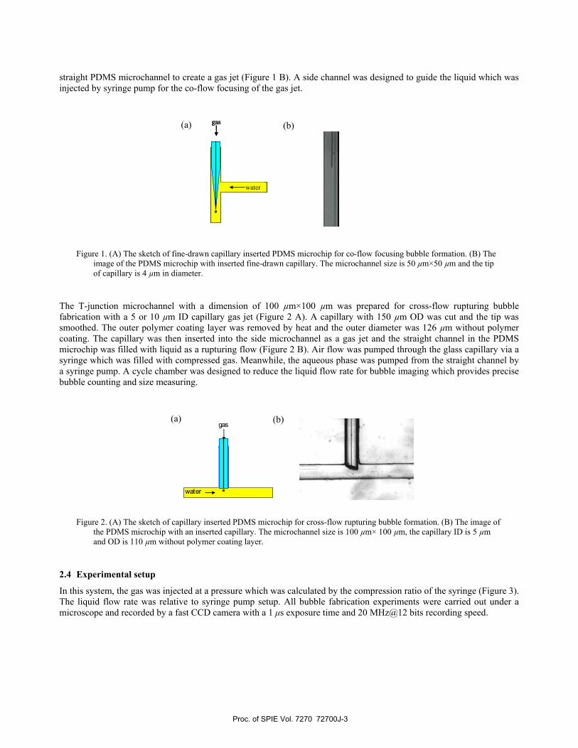
straight PDMS microchannel to create a gas jet (Figure 1 B). A side channel was designed to guide the liquid which was injected by syringe pump for the co-flow focusing of the gas jet.
Figure 1. (A) The sketch of fine-drawn capillary inserted PDMS microchip for co-flow focusing bubble formation. (B) The
image of the PDMS microchip with inserted fine-drawn capillary. The microchannel size is 50 µm×50 µm and the tip of capillary is 4 µm in diameter.
The T-junction microchannel with a dimension of 100 µm×100 µm was prepared for cross-flow rupturing bubble fabrication with a 5 or 10 µm ID capillary gas jet (Figure 2 A). A capillary with 150 µm OD was cut and the tip was smoothed. The outer polymer coating layer was removed by heat and the outer diameter was 126 µm without polymer coating. The capillary was then inserted into the side microchannel as a gas jet and the straight channel in the PDMS microchip was filled with liquid as a rupturing flow (Figure 2 B). Air flow was pumped through the glass capillary via a syringe which was filled with compressed gas. Meanwhile, the aqueous phase was pumped from the straight channel by a syringe pump. A cycle chamber was designed to reduce the liquid flow rate for bubble imaging which provides precise bubble counting and size measuring.
Figure 2. (A) The sketch of capillary inserted PDMS microchip for cross-flow rupturing bubble formation. (B) The image of
the PDMS microchip with an inserted capillary. The microchannel size is 100 µm× 100 µm, the capillary ID is 5 µm and OD is 110 µm without polymer coating layer.
2.4 Experimental setup
In this system, the gas was injected at a pressure which was calculated by the compression ratio of the syringe (Figure 3). The liquid flow rate was relative to syringe pump setup. All bubble fabrication experiments were carried out under a microscope and recorded by a fast CCD camera with a 1 µs exposure time and 20 MHz@12 bits recording speed.
water
gas(a) (b)
water
gas
water
gas
water
gas(a) (b)
Proc. of SPIE Vol. 7270 72700J-3

r,I
Figure 3. Image of the experimental setup for bubble fabrication.
3. RESULTS AND DISCUSSION 3.1 Co-flowing bubble generation
In this geometry, the nozzle axis is parallel to the liquid stream. Bubbles were formed as a result of the break-up of the gas jet in the liquid sheath flow. To obtain the optimal conditions for achieving small bubbles, different gas pressures and liquid flow rates were used. Due to the mass transfer process, gas bubbles were dissolved rapidly after formation. PEG was added to the water stream in order to form a bubble shell to increase bubble lifetime. A balance between the high liquid flow rate and the low gas pressure is crucial to make smaller bubbles at a high production rate. The high liquid flow rate could reduce the bubble size effectively. With a 4.5 mL/hr liquid flow rate and 1.5 atm gas pressure, the bubble size was 13 µm. But the bubble number concentration was quite low compared with the high gas pressure situation. If the gas pressure was increased to 1.7 atm and the liquid flow rate decreased to 3.5 mL/hr, the bubble size was 15 µm (Figure 4 A) but the bubble generation rate was increased by 6-fold in comparison with that of the previous process. If the liquid flow rate was further reduced to 2.5 mL/hr, the bubble size was slightly increased to 16 µm and the bubble number concentration was a further 14-fold increased (Figure 4 B). If gas pressure was increased to 3.2 atm, the bubble size was expanded to 17 µm with the bubble number concentration increased by 36-fold. In this design, the reproducibility is a challenge because it is difficult to replicate the glass capillary tip when the capillary is pulled to a couple of micrometers in diameter.
Figure 4. The CCD image of microbubble fabricated with (A) 3.5 ml/hr and 1.7 atm gas pressure and (B) 2.5 ml/hr and 1.7
atm gas pressure in 2 mM PEG solution.
3.2 Cross-flow bubble generation
A similar trend was observed in the cross-flow rupturing method of bubble fabrication. Higher gas pressure offers higher bubble generation rate and higher liquid flow rate gives smaller bubble size.[23] In this design, 5 µm and 10 µm ID capillaries were compared in order to determine the magnitude of the gas jet effect on bubble size. It was found that the
(a)
(b)
50 µm
Proc. of SPIE Vol. 7270 72700J-4

larger ID gas jet required a much higher liquid flow rate to reduce the bubble diameter which resulted in a quite low bubble number concentration. Even with a high liquid flow rate (3.6 mL/hr) and a low gas pressure (2.9 atm), the bubble size (37 µm) was still not competitive (Figure 5 A). A smaller ID capillary gas jet is crucial for smaller size microbubble fabrication. However, there is an obstacle to utilize a 2 µm ID capillary in this microbubble fabrication microchip because of capillarity and a high resistance to gas flow. A 5 µm ID capillary then was introduced into this microchip as a gas jet and a quite attractive result has been achieved. Comparing with the 10 µm ID capillary microchip, this microchip generated 15 µm bubble with a slight lower gas pressure (2.4 atm) and a similar liquid flow rate (3.5 mL/hr), and achieved 7.5-fold higher bubble number concentration (Figure 5 B). If the liquid flow rate was decreased to 1.5 mL/hr, the bubble number concentration was doubled with the sacrifice of a bubble size increase to 25 µm (Figure 5 C).
Figure 5. Bubble images from 10 µm ID capillary inserted microchip with a gas pressure of 2.9 atm and liquid flow rate of
3.5 mL/hr (A), 5 µm ID capillary with gas pressure of 2.4 atm and liquid flow rate of 3.5 mL/hr (B) and gas pressure of 2.7 atm and liquid flow rate of 1.5 mL/hr (C). The liquid is 2 mM PEG solution.
More experiments were carried out to investigate the relationship between the liquid flow rate/gas pressure and bubble size/bubble generation rate. Gas pressure was changed from 2 atm to 10 atm while the liquid flow rate from 2 mL/hr to 8 mL/hr. The bubble size and its number concentration were measured when the bubble was blown off from the capillary jet, in the middle of a straight channel and in the circular chamber.There is a linearity between the bubble size and the liquid flow rate (Figure 6). The bubble diameter was inversely proportional to the speed of liquid flow which was quantified by the quotient of the liquid flow rate and the cross-sectional area. However, the dependence of the bubble size on the gas pressure was not linear (Figure 7). At smaller gas pressures, increases could induce a pronounced increase of bubble size. At higher pressures, the size increase was minimal, but the bubble generation rate was increased, as shown in Figure 8. This trend reveals that with the combination of high liquid flow rate and gas pressure, it is possible to fabricate smaller microbubbles with high bubble number concentration. The bubble size was down to 11 µm when the gas pressure was 2 atm with the liquid flow rate of 8 mL/hr. If the gas pressure was increased to 10 atm, the bubble size was only slightly increased to 13.4 µm. When the pressure was increased from 5 atm to 10 atm, its contribution to bubble size was only 2 %. But the bubble number concentration was increased by 36-fold when the pressure was increased from 2 atm to 10 atm. If a high force syringe pump could be used in this device and the leakage of the connection and PDMS microchip could be avoided, a smaller size of microbubble with high number concentration could be expected. This finding will be very useful in the future work in cases where the bubble size and number concentration are both crucial for ultrasound contrast agent fabrication, for example, in the deliver of expensive drugs.
(a)
(b)
(c)
100 µm
Proc. of SPIE Vol. 7270 72700J-5

Figure 6. The relationship between the bubble size and the liquid flow rate. The bubble size was measured when it passed
through the circular chamber.
Figure 7. The relationship between the bubble size and the gas pressure. The bubble size was measured when it was blown
off from the capillary jet with the liquid flow rate of 8 mL/hr.
10
11
12
13
14
15
2 4 6 8 10 12
Gas pressure (atm)
Bub
ble
size
(µm
)
10
11
12
13
14
15
2 4 6 8 10 12
Gas pressure (atm)
Bub
ble
size
(µm
)
10
12
14
16
18
20
22
24
0 2 4 6 8 10
Flow rate (mL/hr)
Bub
ble
size
(µm
)
5 atm3.33 atm2.5 atm2 atm
10
12
14
16
18
20
22
24
0 2 4 6 8 10
Flow rate (mL/hr)
Bub
ble
size
(µm
)
5 atm3.33 atm2.5 atm2 atm
Proc. of SPIE Vol. 7270 72700J-6

Q'O
Do,,.
S S S S S S
$
*
S
0
0
000
00
Figure 8. The bubble is generated by 5 µm ID capillary inserted microchip with liquid flow rate of 8 mL/hr under the gas pressure of 10 atm (A), 5 atm (B), 3.33 atm (C), 2.5 atm (D) and 2 atm (E). The images are taken from the capillary insertion section, the middle of the channel, and the circular chamber in the microchip.
4. CONCLUSIONS A novel microfluidic bubble generation chip has been prototyped. It incorporates a T-junction PDMS microchannel network and an inserted glass capillary. The flow rate of liquid, gas pressure and the inserted capillary inner diameter were found to be crucial for control of the bubble size. With co-flowing liquids and a smaller diameter capillary, bubbles with a size of 13 µm could be generated reliably after optimizing the liquid flow rate and gas pressure. It was found from the series of experiments that the 5 µm capillary produced 11 µm diameter bubbles. With a high liquid flow rate and gas pressure, the micro-scale bubbles could be fabricated with a high generation rate.
(a)
(b)
(c)
(d)
(e)
100 µm
Proc. of SPIE Vol. 7270 72700J-7
REFERENCES
[1] Choi, J., Wang, S., Tung, Y.-S., Morrison B. and Konofagou, E., "Trans-blood-brain barrier delivery of compounds at pharmacologically relevant molecular weights in the hippocampus of mice using Focused Ultrasound," J. Acoust. Soc. Am, 123, 3217 (2008).
[2] Hettiarachchi, K., Talu, E., Longo, M. L., Dayton, P. A. and Lee, A. P., "On-chip generation of microbubbles as a practical technology for manufacturing contrast agents for ultrasonic imaging," Lab Chip 7, 463-468 (2007).
[3] Xu, J. H., Luo, G. S., Li, S. W. and Chen, G. G., "Shear force induced monodisperse droplet formation in a microfluidic device by controlling wetting properties," Lab Chip 6, 131-136 (2006).
[4] Liu, Y., Miyoshi, H. and Nakamura, M., "Encapsulated ultrasound microbubbles: Therapeutic application in drug/gene delivery," J. Contr. Rel. 114, 89-99 (2006).
[5] Xu, J. H., Li, S. W., Wang, Y. J. and Luo, G. S., "Controllable gas-liquid phase flow patterns and monodisperse microbubbles in a microfluidic T-junction device," Appl. Phys. Lett. 88, 1335061-1335063 (2006).
[6] Gañán-Calvo, A. M. and Gordillo, J. M., "Perfectly Monodisperse Microbubbling by Capillary Flow Focusing," Phys. Rev. Lett. 87, 2745011-2745014 (2001).
[7] Pancholi, K., Farook, U., Moaleji, R., Stride, E. and Edirisinghe, M., "Novel methods for preparing phospholipid coated microbubbles," Eur. Biophys. J. 37, 515-520 (2008).
[8] Klibanov, A., "Ultrasound Contrast Agents: Development of the Field and Current Status," in Contrast Agents II, 73-106 (2002).
[9] Shintaku, H., Imamura, S. and Kawano, S., "Microbubble formations in MEMS-fabricated rectangular channels: A high-speed observation," Exp. Therm. Fluid. Sci. 32, 1132-1140 (2008).
[10] Zhu, Y. and Power, B. E., “Lab-on-a-chip in vitro compartmentalization technologies for protein studies”, in Adv. Biochem. Eng./Biotech. Vol 110: Protein-Protein Interaction, by (Eds) M. Werther and H. Seitz, Springer, Berlin, 81-114 (2008).
[11] Zhang, W. and Tan, R. B. H., "A model for bubble formation and weeping at a submerged orifice with liquid cross-flow," Chem. Eng. Sci. 58, 287-295 (2003).
[12] Zhang, W. and Tan, R. B. H., "A model for bubble formation and weeping at a submerged orifice," Chem. Eng. Sci. 55, 6243-6250 (2000).
[13] Gañán-Calvo, A. M., "Perfectly monodisperse microbubbling by capillary flow focusing: An alternate physical description and universal scaling," Phys. Rev. E 69, 0273011-0273012 (2004).
[14] Kulkarni, A. A. and Joshi, J. B., "Bubble Formation and Bubble Rise Velocity in Gas-Liquid Systems: A Review," Ind. Eng. Chem. Res. 44, 5873-5931 (2005).
[15] Weber, M. and Shandas, R., "Computational fluid dynamics analysis of microbubble formation in microfluidic flow-focusing devices," Microfluid. Nanofluid. 3, 195-206 (2007).
[16] Xiao, Z. and Tan, R. B. H., "An improved model for bubble formation using the boundary-integral method," Chem. Eng. Sci. 60, 179-186 (2005).
[17] Klibanov, A. L., "Ligand-Carrying Gas-Filled Microbubbles: Ultrasound Contrast Agents for Targeted Molecular Imaging," Bioconjugate Chem. 16, 9-17 (2005).
[18] Talu, E., Lozano, M. M., Powell, R. L., Dayton, P. A. and Longo, M. L., "Long-Term Stability by Lipid Coating Monodisperse Microbubbles Formed by a Flow-Focusing Device," Langmuir 22, 9487-9490 (2006).
[19] Taylor, G. I., “The Formation of Emulsions in Definable Fields of Flow,” Proc. Royal Society of London. Series A, Containing Papers of a Mathematical and Physical Character 146(858), 501-523 (1934).
[20] Dollet, B., Hoeve, W. van, Raven, J.-P., Marmottant, P. and Versluis M., “Role of the Channel Geometry on the Bubble Pinch-Off in Flow-Focusing Devices,” Phys. Rev. Lett. 100, 0345041-0345044 (2008).
[21] Hoeve, W. van, Dollet, B., Sun, C., Lohse D. and Versluis M., “Microbubble pinch-off in flow-focusing devices”, 24th International Congress of Theoretical and Applied Mechanics, Adelaide, Australia, 25-29 August (2008).
[22] Chen, C., and Hahn, J. H., “Dual-Channel Method for Interference-Free In-Channel Amperometric Detection in Microchip Capillary Electrophoresis,” Anal. Chem. 79, 7182-7186 (2007).
[23] Garstecki, P., Fuerstman, M. J., Stone, H. A. and Whitesides, G. M., “Formation of droplets and bubbles in a microfluidic T-junction—scaling and mechanism of break-up,” Lab Chip 6, 437-446 (2006).
Proc. of SPIE Vol. 7270 72700J-8