Microchip Motor Control Solutions
60
© 2019 Weikeng Industrial Co., Ltd. 2019/08/06 Microchip Motor Control Solutions
-
Upload
khangminh22 -
Category
Documents
-
view
0 -
download
0
Transcript of Microchip Motor Control Solutions

© 2019 Weikeng Industrial Co., Ltd. 2019/08/06
Microchip Motor Control Solutions

Team 930
Presenter
Presentation Notes
直流馬達: 直流有刷馬達 · 直流無刷馬達 · 切換式磁阻馬達 交流馬達: 永磁同步馬達· 感應馬達(單相 · 鼠籠式轉子 · 繞線轉子 · VS馬達) · 伺服馬達 · 磁阻馬達 · 新型馬達: 滾珠軸承馬達 · 壓電馬達 · 超音波馬達 · 靜電馬達 · 力矩馬達 特殊馬達: 單極馬達 · 線性馬達 · 步進馬達

Team 930
Agenda
Page 3
Microchip motor control solution MCU 8 / 16 / 32 bit & FPGA update
Analog & Driver for motor control solution
Market & Applications Development Boards & tools

Team 930
Microchip Products
Page 4
Presenter
Presentation Notes
MCU : more than 1886 parts. (@2019.05)

Team 930
Motor Control Solutions
Page 5
MOSFET/ IGBT
AC Input
Motor
Isolation
Temp Sensor
Vref
MOSFET Driver
MCU/DSP /CPU
Op Amp
Supervisor
ADC
PWR Management
What we offer Today

Team 930
Core
Page 6
Presenter
Presentation Notes
2017 worlidwide #1 8bit MCU 2017 worlidwide #6 16bit MCU 2017 worlidwide #6 32bit MCU worlidwide MCU Market Share (1.Renesas, 2. NXP 3. Microchip 4.ST 5.TI)

Team 930
Microcontroller Overview
Page 7
Presenter
Presentation Notes
PIN COUNT:6~361 MEMORY: 0.5K~~8M

© 2019 Weikeng Industrial Co., Ltd. Weikeng Confidential © 2019 Weikeng Industrial Co., Ltd.

Team 930
MCU8 Flexible Peripherals
Page 9
Team 930
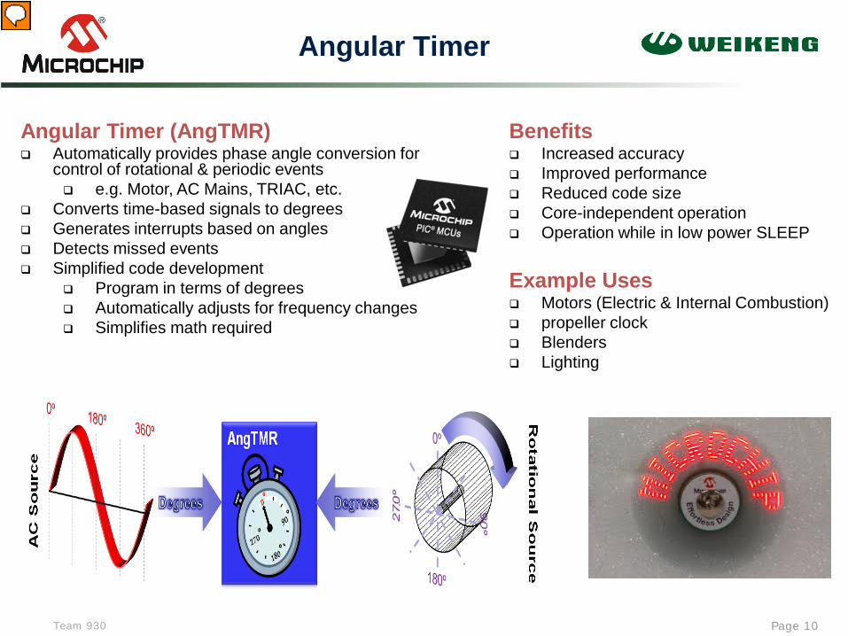
Angular Timer
Page 10
Angular Timer (AngTMR) Automatically provides phase angle conversion for
control of rotational & periodic events e.g. Motor, AC Mains, TRIAC, etc.
Converts time-based signals to degrees Generates interrupts based on angles Detects missed events Simplified code development
Program in terms of degrees Automatically adjusts for frequency changes Simplifies math required
Benefits Increased accuracy Improved performance Reduced code size Core-independent operation Operation while in low power SLEEP
Example Uses Motors (Electric & Internal Combustion) propeller clock Blenders Lighting
Presenter
Presentation Notes
角度計時器:精度達0.36°(1/1000),誤差為0.1° 跑馬燈風扇,TRIAC控制或电容放电式点火系统, CDI Control 利用QRE1113 Minature Reflective Object Sensor(光反射器)

Team 930
Signal Measurement Timer
Page 11
24-bit Signal Measurement Timer (SMT) Accurate measurement of any digital signal
Period, pulse width, frequency, duration, duty cycle, time of flight, etc.
High resolution 24-bit signal measurement Provides relative timing measurements Multiple interrupt sources
Period match, measure period, pulse width (2) Data Capture interrupts
Flexible input sources Useable as a general-purpose 24-bit timer Useable as a custom digital protocol decoder
Benefits Code-size reduction Faster response to changing inputs Core-independent operation Operation while in low-power SLEEP
Example Uses Precise speed control RPM indicators, sensors Range finding Protocol decode
SMT Source Signal
Clock

© 2019 Weikeng Industrial Co., Ltd. Weikeng Confidential © 2019 Weikeng Industrial Co., Ltd.

Team 930
MCU16 for Motor Control
Page 13
dsPIC30F dsPIC33F dsPIC33E
Motor Control PWMs - Up to 16-bit resolution - Complementary/ Independent - Edge/Center – Aligned - Double-Update Mode - Dual Dead-Time Registers - Programmable A/D Triggers - Fault shut-down pins
6 or 8 outputs, single frequency
8 outputs, single frequency;
6 + 2 outputs, dual
frequencies;
12, 16, or 18 outputs, 6, 8 or 9 frequencies,
14 outputs, single frequency;
7X2 outputs, multiple
frequencies;
A/D Converter -Simultaneous 3-phase sampling - Multiple trigger options and Scanning Modes - 3 output data formats - Individual buffer registers
6, 9 or 16 inputs 10-bit, 1 MSPS,
4 Sample & Holds
4 to 24 inputs 10-bit, 1.1 MSPS,
4 Sample and Holds or
12-bit, 500 KSPS, 1 Sample & Hold
Up to 32 inputs 10-bit, 1.1 MSPS,
4 Sample and Holds or
12-bit, 500 KSPS, 1 Sample & Hold
Quadrature Encoder Interface (QEI) - Digital filters on inputs
1 1 or 2 Up to 2, 32 bit QEI
Analog Comparators - 0, 2 or 4 Up to 3
• Motor Control PWMs designed to optimize control loop performance
• Extremely accurate A/D Converter – 9.4 ENOB in 10-bit mode
• Support for all feedback methods – Hall Sensors, BEMF, 3-Phase Current
• Fault Protection – immediate PWM shutdown (~20 ns with comparators)

Team 930
dsPIC33CH128 Family
Page 14
MEMORY BUS
ADC
UARTs
Comp
Inp Cap
Out Cmp
SPIs
PE
RIP
HE
RA
L B
US
Master dsPIC33CH
Core 90 MHz
16KB Data RAM
128KB ECC Flash
PWMS
Timers
DMA
MEMORY BUS
ADCs
UART
Comps PGAs
Inp Cap
Out Cmp
I2C™
SPI
PE
RIP
HE
RA
L B
US
Slave dsPIC33CH
Core 100 MHz
4KB Data RAM
24KB ECC
PRAM
PWMS
Timers
DMA
M –> S FIFO
S –> M FIFO
Mailbox Mailbox Mailbox Mailbox Mailbox Mailbox Mailbox Mailboxes
Configurable direction for all 16 mailboxes Configurable interrupt operation for mailboxes & FIFOs
CAN-FD
I2C™ (2)

Team 930
Context-Selected Register Sets
Page 15
Enables nearly instantaneous context switches
Four additional register sets Each assigned to specific interrupt
priority level
Persistent data from one interrupt service routine (ISR) invocation to the next
Reduces saving and restoring register contents
Accelerates compensators up to 50%
AccA AccB AccA
AccB AccA AccB AccA
AccB AccA AccB
AD39 AD31 AD15 AD0
IPLx
IPLy
IPLz
IPLw
Main
W0 W1 W2 W3 W4 W5 W6 W7 W8 W9
W10 W11 W12 W13 W14
W0 W1 W2 W3 W4 W5 W6 W7 W8 W9
W10 W11 W12 W13 W14
W0 W1 W2 W3 W4 W5 W6 W7 W8 W9
W10 W11 W12 W13 W14
W0 W1 W2 W3 W4 W5 W6 W7 W8 W9
W10 W11 W12 W13 W14
Main IPLx IPLy IPLz
IPLw W0 W1 W2 W3 W4 W5 W6 W7 W8 W9
W10 W11 W12 W13
Frame Ptr / W14
Stack Ptr / W15
Working Registers
Status Register
MSB context selected LSB stacked
IPLx IPLy
IPLz
IPLw Main
Accumulators

Team 930
12-Bit ADC
Page 16
285ns latency
4 SARs – 3.5 MSPS per SAR
2 Dedicated S&H / 1 Shared S&H on Slave
1 Shared S&H on Master
Up to 24 analog inputs each with a dedicated result register
Multiple and flexible trigger options
PWM Primary and Secondary Trigger Timer Period Match Output Compare event trigger PWM special event trigger PWM Current-Limit event trigger External trigger event from device pin Software trigger
Four digital comparators with interrupts:
Multiple comparison options
Four oversampling filters with interrupts:
Provides increased resolution
Slave ADC Block Diagram
Team 930
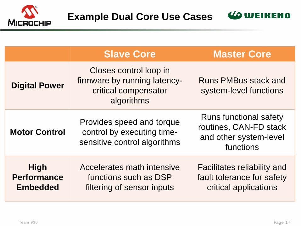
Example Dual Core Use Cases
Page 17
Slave Core Master Core
Digital Power
Closes control loop in firmware by running latency-
critical compensator algorithms
Runs PMBus stack and system-level functions
Motor Control Provides speed and torque control by executing time-
sensitive control algorithms
Runs functional safety routines, CAN-FD stack and other system-level
functions
High Performance Embedded
Accelerates math intensive functions such as DSP filtering of sensor inputs
Facilitates reliability and fault tolerance for safety
critical applications

Team 930
Example Application: Air Conditioner
Page 18
SLAVE Core
dsPIC33CH 100 MIPS
MASTER Core
dsPIC33CH
90 MIPS
Power Factor Correction
Fan
Compressor
Presenter
Presentation Notes
interleaving PFC (PWM 64KHz), Fan & Compressor (都是FOC, PWM 16Khz) Master: PFC executes at 64KHz = 15.6uS PFC needs 3uS = (3/15.6)*100MIPS =20MIPS Slave: FOC executes at 16KHz = 62.5uS Each FOC (motor) needs 16uS =(16/62.5)*100 = 26MIPS

Team 930
dsPIC33EDV64MC205 w/ Integrated FET Drivers
Page 19
MEMORY BUS
9 Channel 10/12-bit ADC
I2C – 2
Analog Comp / Op-Amp – 3 Analog Comp – 1
Input Capture/Output Compare – 4/4
16-bit Timers – 6
Peripheral Trigger Generator (PTG)
UART with LIN – 1
SPI – 2
Operating Voltage : 6.0-28 V
Operating temperature: -40˚C to 150˚C
dsPIC33 Core 70 MIPS
16-bit ALU
17x17 MPY
16x16 Register
JTAG & EMU
Barrel Shifter
Address Generation
64 KB Flash
8 KB RAM 4 CH DMA
Motor Control PWM – Internal
Charge Time Measure Unit (CTMU)
AEC-Q100 Grade 0 Qualification
PE
RIP
HE
RA
L B
US
Quadrature Encoder Interface (QEI)
CRC
Per
iph
eral
Pin
Sel
ect (
PP
S)
OSC POR/BOR Windowed
WDT Analog System
3.3V LDO
12V Gate
Voltage Supervisor
Comm. Port
Internal 1% Oscillator
3 half-bridge drivers configured to drive external high-side NMOS and low-side NMOS MOSFETs
Presenter
Presentation Notes
Not release yet.

© 2019 Weikeng Industrial Co., Ltd. Weikeng Confidential © 2019 Weikeng Industrial Co., Ltd.

Team 930
MCU32 Device Families
Page 21

Team 930
PIC32MK MC Family migration from dsPIC33
Page 22
• PIC24 CPU • 70 MHz / ~70 DMIPS
• 16KB– 512KB Flash • 2KB – 48KB RAM • 4KB EEPROM
• Single or Dual 3-phase MC PWM
• 10-bit ADC – up to 8 S/H • Up to 4 Op-amps • USB, CAN
• 125˚C, Q100
dsPIC33EP GM Family
0.18u
• MIPS microAptiv core • 120 MHz / 150 DMIPS
• 16KB – 1MB Flash • 2KB – 256KB RAM • 4KB EEPROM
• Single or Dual 3-phase MC PWM
• Up to 7 x 12-bit SAR ADC • Up to 4 Op-amps • Up to 3×12-bit DAC • USB, CAN
• 125˚C, Q100 planned
PIC32MK MC Family
90nm Advance Information
More Performance More Flash & RAM Powerful, Full featured Motor Control

Team 930
PIC32MK MC Family High-end
Page 23
HIGH SPEED BUS MATRIX Bridge
Peripheral Bus (SYSCLK)
PO
RT
A
PO
RT
B
PO
RT
C
PO
RT
D
PO
RT
E
PO
RT
F
PO
RT
G
Advance Information
Peripheral Pin Select (PPS) F
S U
SB
FS
US
B
CA
N-F
D 1
DM
AC
CR
C
PM
P
PW
M / O
C
x9
IC x9
System Resources
POR Reset
BOR Reset
8 MHz Osc
32 KHz Osc
WDT Timer
Xtal Osc
PLL
JTAG
MIPS®
microAptivTM
32-bit CPU+DSP+FPU
Instruction Pre-fetch
1 MB Flash w/ ECC
Pre-fetch
UA
RT
1-6
SP
I / I²S
1-6
Comparator ×5
256KB SRAM
RT
CC
TIM
ER
1-9
3 × 12-bit DAC
7 × 12-bit ADC 3.75 Msps each
CA
N-F
D 2
CA
N –F
D 3
CA
N-F
D 4
Op-amp ×4
PT
G
ICD
MC
PW
M x12
QE
I 1-6

Team 930
PIC32MK MC High-end Family
Page 24
Core Flash RAM
Packages ADC
Modules Timing
Resources
Low Power modes
Comm Modules
Other Modules
MIPS microAptiv™
120 MHz
150 DMIPS
DSP (FPU)
DMA
1 MB 256 KB
64 TQFP 64 QFN
100 TQFP
7×12-bit SAR ADC
2 Msps 7 S/H
Up to 49 Ch
9×Timers 9×IC / 9×OC
12x2 MC PWM RTCC
Deep Sleep
6×UART
6×SPI / I²S
2×USB + PHY
4×CAN-FD
4KB EEPROM
4×OpAmp 5×Analog Comp
3×12-bit DAC PTG PMP PPS
512 KB 128 KB
Advance Information
150 DMIPS / 120 MHz, Up to 1MB Flash / 256KB RAM Advanced Analog, Advanced Motor Control

Team 930
Dedicated ADC core
Page 25
6 independent ADC cores • 3 Selectable/Alternate inputs on each • 1 sample & hold per core • Differential or Single ended input • OPAMPS and COMP outputs directly connected to selection switch

Team 930
Shared ADC core
Page 26
• Shared ADC core ( traditional party line ) • Shared between Class 2 and Class 3 inputs • Shared clock, references and sample hold for all inputs.
Team 930
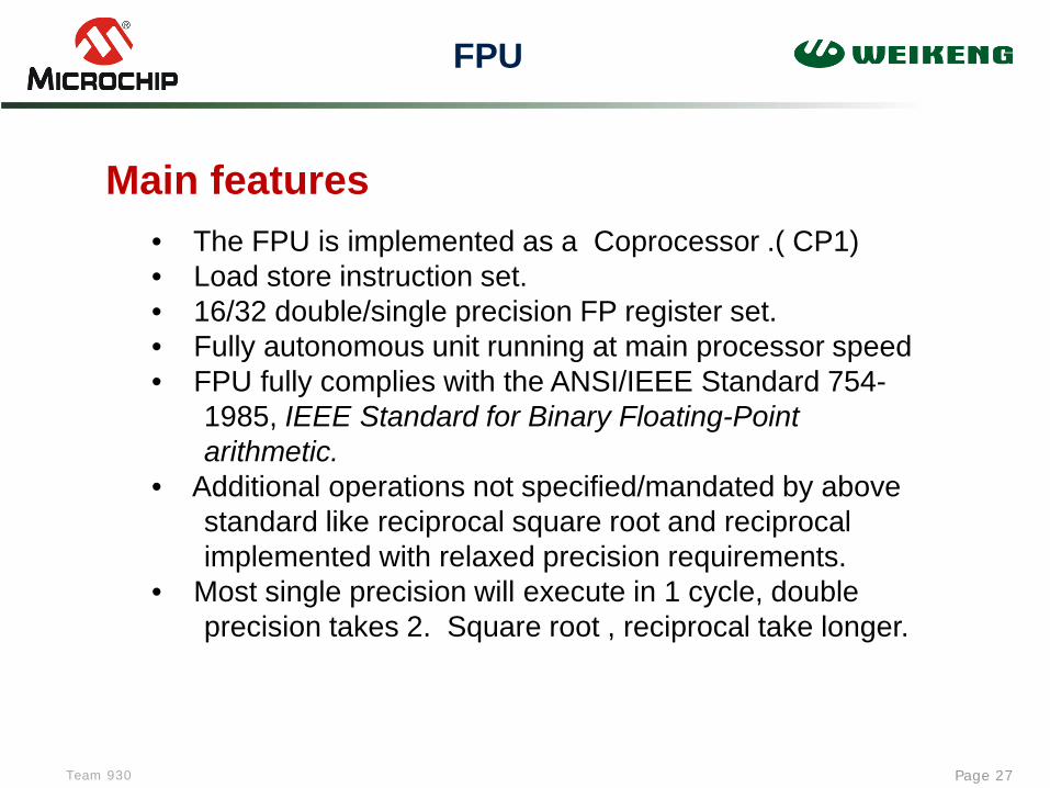
FPU
Page 27
• The FPU is implemented as a Coprocessor .( CP1) • Load store instruction set. • 16/32 double/single precision FP register set. • Fully autonomous unit running at main processor speed • FPU fully complies with the ANSI/IEEE Standard 754- 1985, IEEE Standard for Binary Floating-Point arithmetic. • Additional operations not specified/mandated by above standard like reciprocal square root and reciprocal implemented with relaxed precision requirements. • Most single precision will execute in 1 cycle, double precision takes 2. Square root , reciprocal take longer.
Main features

© 2019 Weikeng Industrial Co., Ltd. Weikeng Confidential © 2019 Weikeng Industrial Co., Ltd.
Presenter
Presentation Notes
Microsemi(原Actel) 是flash架構的FPGA,而Altera和Xilinx的都是SRAM架構,掉電資料丟失,所以一般需要外加一個配置晶片(空間需求也降低)。由於Microsemi 是flash架構的FPGA,所以不要配置晶片,而且功耗更低,尤其適用於對功耗敏感的系統。 Microsemi 與其他公司的FPGA相比的另一個優點就是上電即運行。這個特性有助於系統元件的初始化、處理器喚醒緊急任務的執行,而Altera和Xilinx的FPGA上電到正常工作需要0.2秒的時間。這一點也正是Microsemi 廣泛用於航空或者軍事領域的原 SRAM的FPGA可能在輻射下發生反轉而產生嚴重錯誤。如果採用基於SRAM的FPGA,那麼就需要採用多個晶片的冗餘來防止出錯,其結果是成本將大幅提升。現在該應用大多採用ASIC,而基於flash的FPGA更具有可重複程式設計的特點,是替代ASIC的首選。 不過SRAM的FPGA在計算能力尚還是有優勢的

Team 930
Motion Control FPGA Applications
Page 29
Presenter
Presentation Notes
DSC: digital signal controller

Team 930
Mid-Range FPGA Portfolio
Page 30
Features SmartFusion (SoC), ProASIC3, IGLOO
SmartFusion2 (SoC), IGLOO2
PolarFire
Logic Elements 100–30K 5K–150K 100K–480K
Transceiver Rate 1 Gbps–5 Gbps 250 Mbps–12.7 Gbps
I/O Speeds 400 Mbps LVDS 667 Mbps DDR3 750 Mbps LVDS
1600 Mbps DDR4 1.6 Gbps LVDS
DSP (18x18 Multipliers) 240 1480
Max RAM 144 Kb 5 Mb 33 Mb
Processor Option Hard 100 MHz ARM Cortex-M3
Hard 166 MHz ARM Cortex-M3
Soft RISC-V
Soft RISC-V Soft ARM Cortex-M1
Hard crypto processor
On-board Flash Up to 512 KB code store Up To 512 KB code store 56 KB secure NVM
Family Type CPLD replacements Smallest packages
Low density FPGAs with more resources and the lowest power
Mid-range density FPGAs Lowest power, cost optimized
Presenter
Presentation Notes
這幾顆還是ARM的, RISC-V(发音为“risk-five”)是一個基于精简指令集(RISC)原则的开源指令集架構(ISA),簡易解釋為開源軟體運動相對應的一種「開源硬體」 RISC-V 相較 ARM 架構而言,晶片設計上更具有自由度,授權金與權利金也較為划算,特別在中國積極發展 AI、物聯網產品應用的新創公司中,採用 RISC-V 開發可以更快速、更有效率。對於這幾年中國積極發展半導體,投入大筆資金補助,就是想要看到廠商快速發展見效,因此 RISC-V 具有更大競爭優勢 RISC-V 的特色來說,RISC-V 相較 ARM 來說,具有更高設計彈性,而且能夠任意添加新的指令,對於物聯網裝置破碎化的特性,可說是相對 ARM 而言更加貼合。

Team 930
FPGA Multi-Axis Motor Control Solution Ecosystem
Page 31
Motor control algorithms implemented in FPGA fabric Scalability to a multi-axis motor drive design Design flexibility with modular IP suite Deterministic, high precision, low power, reliable, and secure Robust sensorless solution (supports 100K RPM or more) Integration of system functions to lower total cost of ownership (TCO)
Dual-Axis Motor Control Kit Highly integrated and compact BLDC and stepper motors Encoder and hall-sensor I/F Quick-start card
Motor Control IP Suite Fully modular IP suite Has key IP blocks Enables easy implementation
of all major algorithms for BLDC and stepper motors
Resources and Documentation Demo guide IP user Guides Application notes Libero projects Whitepapers Computer-based trainings
Software, Programming, and Debug GUI-based 2-axis MC software Libero and SoftConsole support Flash programmer

Team 930
6-Axis Motor Control Design
Page 32
6-axis BLDC motor control demonstration available
Maximum DC voltage supported is 48 V
130 V motors can be run at lower speeds
24 V motor can be run at full speed
Soft console, programming file, and GUI available
Kit contents 6-axis motor control board with M2S010 Emcraft SOM
mounted on it
6 BLDC motors
24 V power adapter
Mini USB cable

© 2019 Weikeng Industrial Co., Ltd. Weikeng Confidential © 2019 Weikeng Industrial Co., Ltd.

Team 930
Analog & Interface Products
Page 34

Team 930
SBC for BLDC Motors-MCP8025
Page 35
Presenter
Presentation Notes
System Basis Chips Replace IR2103x3

Team 930
SBC for BLDC Motors-MCP8026
Page 36

Team 930
Motor Gate Driver
Page 37
Presenter
Presentation Notes
主要差異就是 8025只有一組OP, 6~19v,有包LIN 8026有三組OP, 6~28v,但是沒有LIN

Team 930
MIC460x
Page 38

Team 930
SBC for Brushed DC Motors ATA6823C/24C
Page 39

Team 930
Integrated BLDC Driver-MCP8063
Page 40
Presenter
Presentation Notes
三相正弦無感測器無刷馬達驅動器

Team 930
Stepper Driver MTS62C19A/MTS2916A
Page 41

© 2019 Weikeng Industrial Co., Ltd. Weikeng Confidential © 2019 Weikeng Industrial Co., Ltd.

Team 930
Market & Applications
Page 43

Team 930
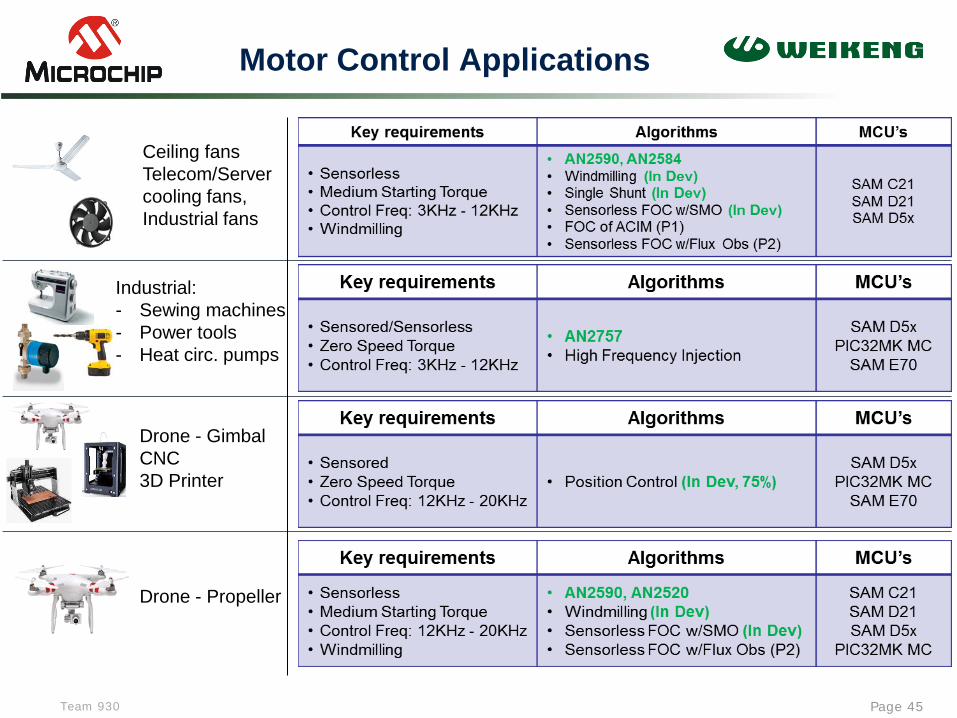
Motor Control Applications
Page 44
HVAC - Compressors - Fans
Refrigerator compressors
Washing machines Dryers
Dishwasher
Team 930
Motor Control Applications
Page 45
Drone - Propeller
Drone - Gimbal CNC 3D Printer
Ceiling fans Telecom/Server cooling fans, Industrial fans
Industrial: - Sewing machines - Power tools - Heat circ. pumps

© 2019 Weikeng Industrial Co., Ltd. Weikeng Confidential © 2019 Weikeng Industrial Co., Ltd.

Team 930
MCLV-2 for Low-Voltage Motors
Page 47
Presenter
Presentation Notes
The rated continuous output current from the inverter is 6.5A (RMS). This allows up to approximately 2 kVA output when running from a 208V to 230V single-phase input voltage in a maximum 30ºC (85ºF) ambient temperature environment. Therefore, the system is ideally suited for running a standard 3-Phase Induction Motor of up to 1.4 kW (1.8 HP) rating or a slightly higher rated industrial servo-motor

Team 930
MCHV for High-Voltage Motors
Page 48
Key Features:
Supports 3-Phase ACIM, BLDC and PMSM
Integrated Power Module (IPM) based design with a power rating of 400V/10A
Feedback Circuit Support:
Hall Sensors
Shaft Encoder (QEI)
BEMF
Single-Shunt for sensorless
Dual-Shunt for sensorless
Over-current protection
PFC circuit included
Built-in Debugger / Programmer
Real-time debugging via DMCI in MPLAB®
Isolated Communication Ports : USB & RS232
Isolated Input/Output control switches
Isolated potentiometer input
LED Indicators for PWM outputs
dsPIC33FJ32MC204 based PIM included
Options:
AC300021 3-Phase ACIM

Team 930
Low Voltage Motor Control Starter Kit
Page 49

Team 930
SBC for BLDC Motors MCP8025
Page 50

Team 930
MTS2916A Demo Board
Page 51

Team 930
MCP8063 Kits
Page 52

Team 930 Page 53
PIC MC Application Notes
Motor Type App. Note Description
Stepper Motor AN907 Stepper Motor Fundamentals
AN1307 Stepper Motor Control with the dsPIC
Brushed DC Motor AN905 Brushed DC Motor Fundamentals
BLDC and PMSM AN857 Brushless DC Motor Control Made Easy
AN885 Brushless DC (BLDC) Motor Fundamentals
AN901 Sensorless Control of BLDC Motor using dsPIC30F6010
AN992 Sensorless Control of BLDC Motor using dsPIC30F2010
AN957 Sensored Control of BLDC Motor using dsPIC30F2010
AN1017 Sinusoidal Control of PMSM Motors with dsPIC30F
AN1083 Sensorless Control of BLDC with Back-EMF Filtering
AN1078 Dual Shunt Sensorless FOC for PMSM
AN1160 Sensorless BLDC Control with Back-EMF Filtering Using a Majority Function
AN1208 Integrated PFC and Sensorless FOC System
AN1292 Dual Shunt Sensorless FOC PSMS PLL Field Weakening
AN1299 Single Shunt Sensorless FOC PMSM SMO
AC Induction Motor AN887 AC Induction Motor Fundamentals
AN908 Using the dsPIC30F for Vector Control of an ACIM
AN984 Introduction to ACIM Control using the dsPIC30F
AN1162 Sensorless Field Oriented Control (FOC) of an ACIM
AN1206 Field Weakening Sensorless FOC for ACIM
Other AN1106 Power Factor Correction on dsPIC® DSC
AN1229 Meeting IEC 60730 Class B Compliance with dsPIC® DSC
Full source code included
Royalty/License free
Optimized performance
Dynamometer tested
Step-by-step tuning guides
All FREE!

Team 930 Page 54
AVR123: AT90PWM81 ADC conversion, optimization versus temperature
AVR194: Brushless DC Motor Control using Atmega32M1
AVR275: Sensor-based Control of Three Phase Brushless DC Motors Using 8-bit AVR USB microcontrollers
AVR435: BLDC/BLAC Motor Control Using a Sinus Modulated PWM Algorithm
AVR440: Sensor-less Control of Two-Phase Brushless DC Motor
AVR441: Intelligent BLDC Fan Controller with Temperature Sensor and Serial Interface
AVR442: BLDC Fan Motor Control with ATtiny13
AVR443: Sensor-based control of three phase Brushless DC motor
AVR444: Sensor-less control of 3-phase BLDC motors based on tinyAVR and megaAVR devices
AVR446: Linear speed control of stepper motor
AVR447: Sinusoidal driving of three-phase permanent magnet motor using ATmega48/88/168
AVR448: Control of High Voltage Three-phase BLDC Motor
AVR449: Sinusoidal driving of 3-phase permanent magnet motor using ATtiny261/461/861
AVR452: Sensor-based Control of Three Phase Brushless DC Motors Using AT90CAN128/64/32
AVR492: Brushless DC Motor control using AT90PWM3
AVR493: Sensor-less Commutation of Brushless DC Motor (BLDC) using AT90PWM3 and ATAVRMC100
AVR494: AC Induction Motor Control Using the constant V/f Principle and a Natural PWM Algorithm
AVR495: AC Induction Motor Control Using the Constant V/f Principle and a Space-vector PWM Algorithm
AVR496: Brushless DC Motor Control using ATtiny861
AVR MC Application Notes

Team 930
MPLAB Harmony 3 Released MC Algorithms
Page 55

Team 930
SCILAB
Page 56
www.scilab.org www.mechatronic-simulation.org www.sim2tronic.com
Presenter
Presentation Notes
SCILAB ([sailab]:Open source software(開源軟體) for numerical computation 建立控制系統數學模型 (頻域分析、系統校正,PID控制參數整定及其系統模擬) Matlab功能全面,包含了多個動態仿真模塊,使用方便,在大學用的比較多。缺點是體積龐大,且並非自由軟體,價格昂貴。� scilab是自由軟體,也具有動態仿真模擬的功能,缺點是模塊較少,不兼容matlab語法,Scilab的特點在於它具有友好的使用者介面和較完善的圖形功能

Team 930
X2C Scope
Page 57
Presenter
Presentation Notes
MPLAB v8.xx RTDM- Real Time Data Monitoring Tool

Team 930
Microchip motor control support center
Page 58

Team 930
Why choose Microchip for MC?
Page 59
We have the perfect part for every application
Innovative on-chip peripherals designed specifically to improve motor control
Free motor control software with application notes and schematics for most control algorithms, to shorten your development cycle
Development tools are specifically designed for motor control to promote rapid prototyping of custom applications
Technical training classes taught by motor control experts and web seminars to quickly familiarize engineers with our devices and the latest motor control algorithms
Large product portfolio of pin and tool compatible devices
Single SW development environment and HW dev. tools
DSP functionality and great peripheral set for Motor Control
Strong support, training courses and webinars
Presenter
Presentation Notes
IDE , TOOL, RTC

Team 930
Page 60